keys to excellence in the practice of process engineering · keys to excellence in the practice of...
TRANSCRIPT
Keys to Excellence in the Practice of Process Engineering
An overview by Scott D. Love, P.E. October 2016
Outline
• What is excellence? • How do I learn about my process? • Learning examples • Summary • Questions?
What makes an excellent process engineer?
• Responsible for: – An operating process, or – The process design of a nascent process
• Has a comprehensive mental “picture” of the process – How it fits into overall plant / facility – Understands all its intricate details
• Heat and material balance • Physical elements (equipment and control system) • Chemical & phase changes (including thermodynamics and kinetics of
each) • Baseline and “fouled” operating states • Startup, shutdown, and upset operating conditions • Hazards and “engineering controls” that mitigate them • Operating procedures (both documented and actual)
In other words, the expert process engineer:
• Has a synthesized understanding of the whole process that enables immediate and effective troubleshooting of problematic process performance.
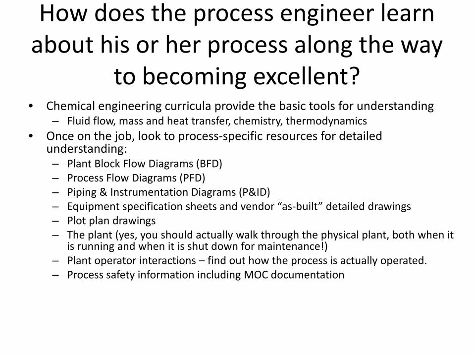
How does the process engineer learn about his or her process along the way
to becoming excellent? • Chemical engineering curricula provide the basic tools for understanding
– Fluid flow, mass and heat transfer, chemistry, thermodynamics • Once on the job, look to process-specific resources for detailed
understanding: – Plant Block Flow Diagrams (BFD) – Process Flow Diagrams (PFD) – Piping & Instrumentation Diagrams (P&ID) – Equipment specification sheets and vendor “as-built” detailed drawings – Plot plan drawings – The plant (yes, you should actually walk through the physical plant, both when it
is running and when it is shut down for maintenance!) – Plant operator interactions – find out how the process is actually operated. – Process safety information including MOC documentation
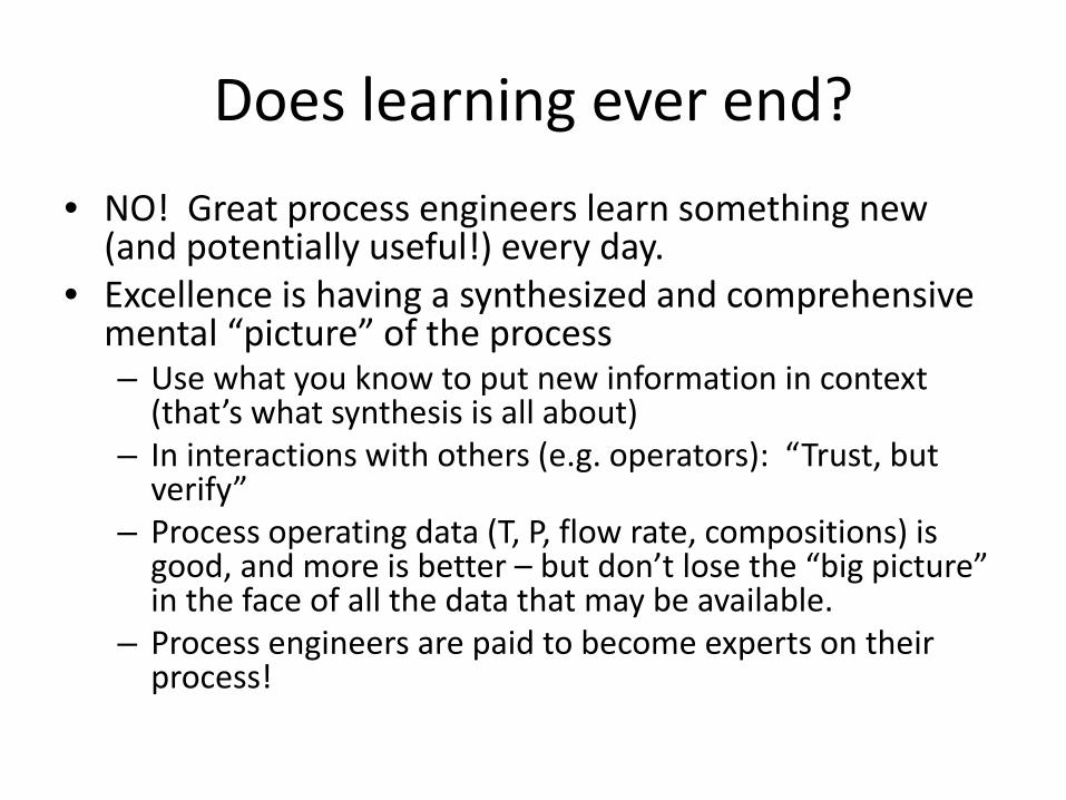
Does learning ever end? • NO! Great process engineers learn something new
(and potentially useful!) every day. • Excellence is having a synthesized and comprehensive
mental “picture” of the process – Use what you know to put new information in context
(that’s what synthesis is all about) – In interactions with others (e.g. operators): “Trust, but
verify” – Process operating data (T, P, flow rate, compositions) is
good, and more is better – but don’t lose the “big picture” in the face of all the data that may be available.
– Process engineers are paid to become experts on their process!
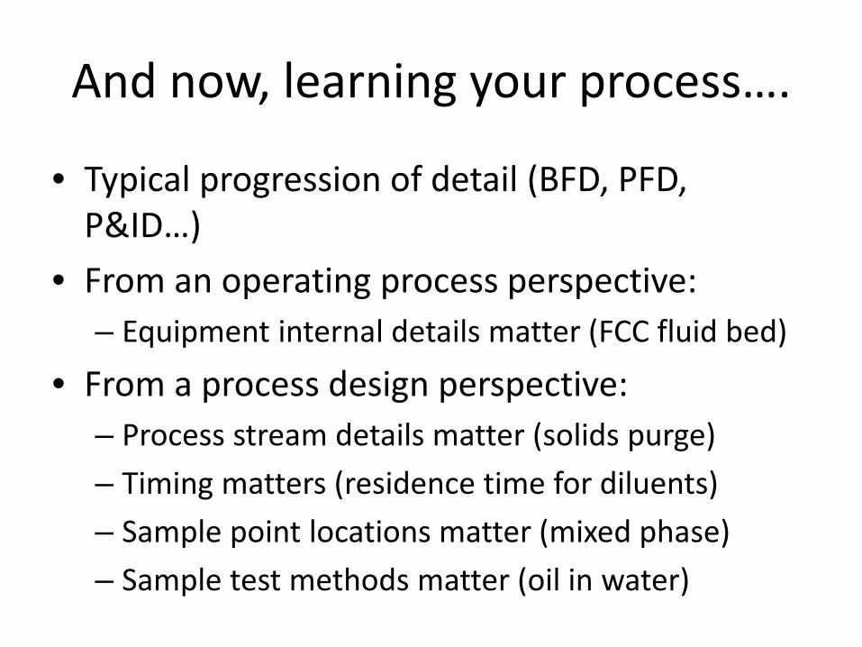
And now, learning your process….
• Typical progression of detail (BFD, PFD, P&ID…)
• From an operating process perspective: – Equipment internal details matter (FCC fluid bed)
• From a process design perspective: – Process stream details matter (solids purge) – Timing matters (residence time for diluents) – Sample point locations matter (mixed phase) – Sample test methods matter (oil in water)
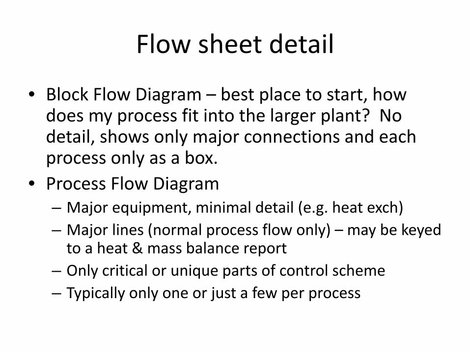
Flow sheet detail
• Block Flow Diagram – best place to start, how does my process fit into the larger plant? No detail, shows only major connections and each process only as a box.
• Process Flow Diagram – Major equipment, minimal detail (e.g. heat exch) – Major lines (normal process flow only) – may be keyed
to a heat & mass balance report – Only critical or unique parts of control scheme – Typically only one or just a few per process

Flow sheets (continued)
• Piping and Instrumentation Diagram – All interconnecting piping (including startup and
shutdown) – may be keyed to heat & mass bal. report – Control scheme (challenge for advanced control
elements) – Line numbers per piping specification (separate
document) showing line size and metallurgy – Some equipment detail (number of trays in towers,
heat exchanger duties and configurations, vessel sizes, etc.)
– May be dozens or even hundreds of sheets per process
Equipment Details (FCC) • A young process engineer in the early ‘80’s was
assigned to a Fluid Catalytic Cracker unit within a crude oil refinery. Unit was designed and built in 1960 and documented detail was scant.
• Continued catalyst losses and catalyst flow problems increased need to understand what process instrumentation was telling him about the conditions within the unit.
• A maintenance shutdown provided the opportunity to physically identify, measure, and validate locations of critical pressure and differential pressure taps within the unit.

Equipment Details (FCC) cont.
• Corrected pressure tap locations enabled accurate assessment of catalyst flows and distribution within the unit – a success!
• Key to success – the process engineer took the initiative to work with Operations and Maintenance personnel for safe personal access to unit during maintenance shutdown period.
Process Stream Details Important?
• At a significant facility in Alberta, Canada – objective was to yield synthetic crude made from produced bitumen
• Production fluid is 75% condensed steam and 25% bitumen. This fluid is blended with “diluent” with the intent of making a mixture of bitumen and diluent that is less dense than water (and meets pipeline minimum density specification).
• Primary phase separation by gravity settling.
Process Stream Details Matter
• Original process design assumed no solids in produced fluid. – No solids handling in primary separation vessels – No solids handling in “slop treater” vessel
• In fact, produced fluid contains significant portion of sub-micron sized neutrally buoyant solids (oil sand particles amalgamated with bitumen components) – Solids-stabilized emulsions in primary separators
recycled and grew in volume, eventually sent off site – “slop treater” vessel filled with solids and abandoned
Process Stream Details Matter
• Eventually, solids handling (sand jet and discharge ports) added to primary separator vessels
• Obviously, post-project fixes were much more expensive than building needed capabilities into original design.
Timing Matters • In the same bitumen production facility… • Diluent is added to the produced fluid – with the
objective of blending with the bitumen portion of that fluid (~25%) – Bitumen portion of that fluid is immiscible second phase in
fair-sized non-homogenous “blobs” – Diluent and demulsifier addition done immediately
upstream of primary separation vessels – less than 5 seconds of mix time (although there is a static mixer)
• There is evidence of incomplete mixing of diluent with bitumen – Solids from vessel are extremely “sticky” – glued with non-
diluted bitumen
Timing Matters
• Longer residence time of mixing would allow more complete mixing of diluent with bitumen
• Longer residence time of mixing would allow proper “induction time” for chemical demulsifier to have its full effect
• While this could have been accounted for fairly easily in the initial design, retrofit would be extremely problematic.

Sample Point Locations
• Facility offshore China producing producing conventional biodegraded shallow oil.
• Complex crude oil chemistry and resultant difficult phase separation led to choice of disk stack centrifuges for final phase separation (sales oil) and produced water deoiling.
• Produced water deoiling seen as already proven technology (used in Norwegian North Sea facilities)
• Sample points in process MUST represent bulk stream within process!
Sample Point Locations
• Initial reports of treated produced water quality were troubling (specification for maximum “oil in water” was very low, initial values were much higher)
• Inspection of facility showed sample points were not going to yield representative samples – Sample points from top of pipes would allow free oil
to accumulate on top of water – Length of sample lines required much higher purge
volume than operators or safety would allow
Sample Point Locations
• Detailed report provided to facility management with concerns and recommendations. – No actions taken due to high cost of revamping
sample points after project completion
• Combination of the presence of immiscible second liquid phase and the extremely low concentration of it specified should have triggered much better follow-through by process engineers on the project.

Sample Test Methods
• At the same facility offshore China: • All maritime authorities have maximum
specification for “oil in water” (OIW) of produced water discharged to the ocean – Typical maximum 25 to 30 ppm – Result highly dependent on test method specified – US EPA specifies method 1664 Silica Gel
Treated N-Hexane Extractable Material (SGT-HEM; Non-Polar Material) by Extraction and Gravimetry.
Sample Test Methods • At this facility, the hexane extracts from samples (arguably
not representative – see previous section) were checked for infrared light absorbance compared to some “standard”.
• For this crude oil and its associated produced water, there were an abundance of water-soluble polar compounds present. – Hexane extracts showed these compounds as “oil in water” – Values from water samples before and after centrifugation
showed no change – Centrifugation (and any other physical process) works only on
separating immiscible liquid phases by their differing densities – Conclusion by operators was that centrifugation was ineffective – EPA method was not suitable for offshore use

Sample Test Methods
• Approximately 30 representative produced water sample sets (centrifuge feed and centrate) were collected and express-shipped to an onshore domestic laboratory for testing using the EPA method 1664.
• 29 of thirty sample sets showed significant reduction in OIW and outlet values less than 30 ppm – suitable for overboarding.
• Thus, the process worked as designed! (but the operators would continue to struggle with the only test method they could do)
Summary • Learn all you can about your process from existing
documentation. • Visit the process “face to face” and put the physical plant
into context with the flowsheet documentation. – Locate sample points and major sensor locations – Observe operators taking samples – Interact with operators – ask questions about their procedures
• Learn how the critical lab tests are done and their significance in light of what is important to your process.
• For capital projects, follow the process from conception through detailed design and construction to minimize issues with sample point locations and residence time concerns.