ki wan bong, stephen c. chapin, and patrick s....
TRANSCRIPT

8008 DOI: 10.1021/la904903g Langmuir 2010, 26(11), 8008–8014Published on Web 02/23/2010
pubs.acs.org/Langmuir
© 2010 American Chemical Society
Magnetic Barcoded Hydrogel Microparticles for Multiplexed Detection
Ki Wan Bong, Stephen C. Chapin, and Patrick S. Doyle*
Department of Chemical Engineering, Massachusetts Institute of Technology, 77 Massachusetts Avenue,Cambridge, Massachusetts 02139
Received December 29, 2009. Revised Manuscript Received February 10, 2010
Magnetic polymer particles have been used in a wide variety of applications ranging from targeting and separation todiagnostics and imaging. Current synthesis methods have limited these particles to spherical or deformations of sphericalmorphologies. In this paper, we report the use of stop flow lithography to produce magnetic hydrogel microparticles with agraphical code region, a probe region, and a magnetic tail region. These anisotropic multifunctional magnetic polymerparticles are an enhanced version of previously synthesized “barcoded” particles ( Science, 2007, 315, 1393-1396) developedfor the sensitive and rapid multiplexed sensing of nucleic acids. The newly added magnetic region has acquired dipolemoments in the presence of weak homogeneous magnetic fields, allowing the particles to align along the applied fielddirection. The novel magnetic properties have led to practical applications in the efficient orientation and separation of thebarcoded microparticles during biological assays without disrupting detection capabilities.
Introduction
Magnetic polymer particles consist of magnetically addressablecomponents entrapped within or coated on a polymer matrix thatcan be precisely tuned to exhibit a range of desired physical andchemical properties. This powerful combination of functionality andcustomization has enabled the use of such particles in biomedicalapplications,1-4 microscale assembly,5-8 structural color printing,9
imaging,10 and purification technology.11 In addition, the particles
have been employed in microfluidic channels for bioassays,12-15
mixing,16-18 trapping,19 transporting,20 and separation.21-25
Recently, biological entities including cells and aptamers werelabeled withmagnetic polymer particles and subsequently separatedin a spatially addressable sorting manner by generating magneticfield gradients in microfluidic channels.26,27
The enormous potential of magnetic polymer particles hasfueled the development of several distinct synthesis methods. Theconventional emulsification methods based on homogenizationuse shear forces to encase superparamagnetic nanoparticles ofmetal oxides within polymer droplets.28 Unfortunately, theseapproaches produce droplets with a wide size distribution andconsume large amounts of energy.28 Membrane29 and micro-channel emulsifications30-32 have been introduced as alternativemethods that can provide higher degrees of monodispersity for afraction of the energy cost. Microchannel emulsification inparticular has produced anisotropic magnetic gel particles usingchannel geometries30 or a double emulsion technique.31 Janussuperparamagnetic gel particles have also been generated withthis approach.32 However, the above methods have limited theparticle morphologies to spheres or deformed spheres.28-32 Amore flexible synthesis system would expand the possible geome-tries and thereby augment the applicability of the magneticpolymer particles produced.
Encoded microparticles have been suggested as diagnostictools for the rapid, multiplexed screening of biomoleculesdue to their advantages in detection and quantification.33-35
*Corresponding author. E-mail: [email protected].(1) Millman, J. R.; Bhatt, K. H.; Prevo, B. G.; Velev, O. D.Nat. Mater. 2005, 4,
98–102.(2) Lee, D.; Cohen, R. E.; Rubner, M. F. Langmuir 2005, 21, 9651–9659.(3) Lee, D.; Cohen, R. E.; Rubner, M. F. Langmuir 2007, 23, 123–129.(4) Voltairas, P. A.; Fotiadis, D. I.; Michalis, L. K. J. Biomech. 2002, 35, 813–
821.(5) Doyle, P. S.; Bibette, J.; Bancaud, A.; Viovy, J. L. Science 2002, 295, 2237–
2237.(6) Smoukov, S. K.; Gangwal, S.; Marquez, M.; Velev, O. D. Soft Matter 2009,
5, 1285–1292.(7) Helseth, L. E. Langmuir 2005, 21, 7276–7279.(8) Helseth, L. E.; Muruganathan, R. M.; Zhang, Y.; Fischer, T. M. Langmuir
2005, 21, 7271–7275.(9) Kim,H.; Ge, J.; Kim, J.; Choi, S.; Lee, H.; Lee, H.; Park,W.; Yin, Y.; Kwon,
S. Nat. Photonics 2009, 3, 534–540.(10) Hoehn, M.; Kustermann, E.; Blunk, J.; Wiedermann, D.; Trapp, T.;
Wecker, S.; Focking,M.; Arnold, H.; Hescheler, J.; Fleischmann, B. K.; Schwindt,W.; Buhrle, C. Proc. Natl. Acad. Sci. U.S.A. 2002, 99, 16267–16272.(11) Berensmeier, S. Appl. Microbiol. Biotechnol. 2006, 73, 495–504.(12) Peyman, S. A.; Iles, A.; Pamme, N. Lab Chip 2009, 9, 3110–3117.(13) Hayes, M. A.; Polson, N. A.; Phayre, A. N.; Garcia, A. A. Anal. Chem.
2001, 73, 5896–5902.(14) Choi, J. W.; Oh, K. W.; Thomas, J. H.; Heineman, W. R.; Halsall, H. B.;
Nevin, J. H.; Helmicki, A. J.; Henderson, H. T.; Ahn, C. H. Lab Chip 2002, 2, 27–30.(15) Gijs, M. A. M.; Lacharme, F.; Lehmann, U., Chem. Rev. 2009, 10.1021/
cr9001929.(16) Rida, A.; Gijs, M. A. M. Appl. Phys. Lett. 2004, 85, 4986–4988.(17) Biswal, S. L.; Gast, A. P. Anal. Chem. 2004, 76, 6448–6455.(18) Rida, A.; Gijs, M. A. M. Anal. Chem. 2004, 76, 6239–6246.(19) Lee, C. S.; Lee, H.; Westervelt, R.M.Appl. Phys. Lett. 2001, 79, 3308–3310.(20) Deng, T.; Whitesides, G. M.; Radhakrishnan, M.; Zabow, G.; Prentiss, M.
Appl. Phys. Lett. 2001, 78, 1775–1777.(21) Ostergaard, S.; Blankenstein, G.; Dirac, H.; Leistiko, O. J. Magn. Magn.
Mater. 1999, 194, 156–162.(22) Pamme, N.; Manz, A. Anal. Chem. 2004, 76, 7250–7256.(23) Pamme, N. Lab Chip 2006, 6, 24–38.(24) Pamme, N. Lab Chip 2007, 7, 1644–1659.(25) Zhang, K.; Liang, Q. L.; Ma, S.; Mu, X. A.; Hu, P.; Wang, Y. M.; Luo, G.
A. Lab Chip 2009, 9, 2992–2999.
(26) Lou, X. H.; Qian, J. R.; Xiao, Y.; Viel, L.; Gerdon, A. E.; Lagally, E. T.;Atzberger, P.; Tarasow, T.M.; Heeger, A. J.; Soh, H. T.Proc. Natl. Acad. Sci. U.S.A. 2009, 106, 2989–2994.
(27) Adams, J. D.; Kim, U.; Soh, H. T. Proc. Natl. Acad. Sci. U.S.A. 2008, 105,18165–18170.
(28) Yuan, Q. C.; Williams, R. A. China Particuology 2007, 5, 26–42.(29) Vladisavljevic, G. T.; Williams, R. A.Adv. Colloid Interfac. 2005, 113, 1–20.(30) Hwang, D. K.; Dendukuri, D.; Doyle, P. S. Lab Chip 2008, 8, 1640–1647.(31) Chen, C. H.; Abate, A. R.; Lee, D. Y.; Terentjev, E. M.; Weitz, D. A. Adv.
Mater. 2009, 21, 3201–3204.(32) Yuet, K. P.; Hwang, D. K.; Haghgooie, R.; Doyle, P. S., Langmuir 2009,
DOI: 10.1021/la903348s.(33) Pregibon, D. C.; Toner, M.; Doyle, P. S. Science 2007, 315, 1393–1396.(34) Wilson, R.; Cossins, A. R.; Spiller, D. G. Angew. Chem., Int. Ed. 2006, 45,
6104–6117.(35) Birtwell, S.; Morgan, H. Integr. Biol. 2009, 1, 345–362.

DOI: 10.1021/la904903g 8009Langmuir 2010, 26(11), 8008–8014
Bong et al. Article
Compared to traditional planar arrays, particle-based arraysoffereasier probe-set modification, more efficient mixing steps, andhigher degrees of reproducibility. While polymer microspheresdoped with fluorescent dyes have been used most extensively,36
there are numerous systems under development that employchemical, graphical, electronic, or physical encoding schemesfor use in multiplexed detection.34 Microcarriers fabricated froma variety of advanced materials such as inverse-opaline photonicbeads37 have the potential to transform the biodiagnostic field byenabling the analysis of complex sample media (such as serum),eliminating the need for costly and time-consuming labeling steps,and lowering limits of detection.
Barcoded hydrogels are an emerging subclass of encodedparticles that exhibit higher sensitivities and more favorablehybridization kinetics than common metallic and polystyrenemicroparticles that immobilize probe species on solid surfaces.38
To capture targetmolecules and report interaction information inmultiplexed analysis, each anisotropic particle bears a proberegion and a corresponding graphical code region that identifiesthe probe species. Production of these particles requires a novelsynthesis method called stop flow lithography (SFL),39 whichaffords precise control over morphology and functionalitythrough the semicontinuous photopolymerization across coflow-ing laminar streams of various chemical compositions in micro-fluidic channels. While the resulting gel-based particles haveproven to be effective tools in past multiplexed sensing of DNAand RNA, their use in suspension assays and other screeningprocesses would be greatly simplified with the introduction of anappropriate means for addressing and aligning the particlesduring rinsing, mixing, and analysis procedures.
Magnetic barcoded particles are now introduced as an en-hanced version of hydrogel microparticles for suspension assaysthat can be manipulated using magnetic fields. Through a slightmodification of the SFL technique,39 it is now possible toincorporate magnetically addressable entities within a specificregion of themicroparticles. Particles synthesizedwith amagnetictail region respond toweakmagnetic fields, while still maintainingthe ability to sensitivity and specifically detect oligonucleotidetargets in solution. The advantages of the magnetic tail aredemonstrated through directed orientation aswell as bulk separa-tion using a magnet.
Experimental Section
Materials. All particles shown in this work were made frompoly(ethylene glycol) (700) diacrylate (PEG-DA 700, Sigma-Aldrich). The code regions were synthesized using prepolymersolutions of 35% (v/v) PEG-DA 700, 20% poly(ethylene glycol)(200) (PEG 200, Sigma-Aldrich), 5% Darocur 1173 (Sigma-Aldrich) initiator, and 40% 3� Tris-EDTA (pH = 8.0, EMD)buffer. Rhodamine acrylate (Sigma-Aldrich) and food coloring(ToneBrothers Inc.) weremixed into the prepolymer solutions forthe code to give final concentrations of 0.4% and 2%, respec-tively. The composition of prepolymer for the probe regions was20% PEG-DA 700, 40% PEG 200, 5% Darocur 1173, and 35%3� Tris-EDTA buffer. Oligonucleotide probes, no. 1 (50-ATAGCA GAT CAG CAG CCA GA-30) and no. 2 (50-CAC TATGCG CAG GTT CTC AT-30), were purchased from IDT withacrydite modifications on the 50 end and mixed into the probeprepolymer to give a final concentration of 50 μM. Lastly, the
magnetic region was prepared using solutions of 35% PEG-DA700, 5% Darocur 1173, and 60% magnetic bead solutions(Seradyn Inc., carboxylate-modified, 5% solids). Prior to beingincorporated into the particles, the commercial superparamag-netic beads exhibited a short response time upon the introductionof a magnetic field and had uniform size (779 nm (10%,diameter).40 Using alternating gradient magnetometry (AGM,MicroMag 2900), the measured saturation magnetization valuesfor the beads (dried) and themagnetic regions (dried) of barcodedparticles were found to be 28 emu/g and 3 emu/g, respectively(Supporting Information). As the mass of each barcoded micro-particle varied depending on the code design, we polymerizedparticles consisting of only a magnetic region and measured themagnetization value for these simple hydrogels. A perfusionsolution consisting of PEG-DA 700 was also used to moveunincorporated magnetic beads into a waste reservoir to preventthe excess beads from sticking to the probe and code regions of thesynthesized particles.
Microfluidic Devices.Microfluidic devices were generated bypouring PDMS (mixed at a base-to-curing agent ratio of 10:1)over an SU-8 master and then curing 2 h at 60 �C in an oven. Ineach device, the particle synthesis chamber was 300 μm in widthand 20 μm in height, while the perfusion channel was 70 μm inwidth and 110 μm in height. Each device was placed on a PDMS-coated glass slide and then sealed by curing overnight at 60 �C inan oven. For synthesis, devices were mounted on an invertedmicroscope (Axiovert 200, Zeiss) equipped with a VS25 shuttersystem (UniBlitz) to precisely control the UV exposure dose.39
A reservoir was cut into the PDMS to collect the particles.
Stop Flow Lithography Setup. We generated controlledpressures in the range of 0-15 psia from house air using a Type100LRmanual pressure regulator (Controlair Inc.).Downstreamof the regulator, a 3-way solenoid valve (Burkert) was used toswitch rapidly between atmospheric pressure (stop) and the inputpressure (flow). The output from the 3-way valve was connectedto 200 μL pipet tips (Molecular BioProducts) using rubber tubing(Tygon). The pipet tips were filled with ∼100 μL of the desiredprepolymer solution and inserted into the channel inlet ports. The3-way valve and above shutter were controlled using a customwritten script in Labview 8.1 (National Instruments).
Photopolymerization Setup. Photomasks were designed inAUTOCAD 2005 and printed using a high-resolution printer atCAD Art Services (Bandon, OR). The mask was then insertedinto the field-stop of the microscope. A Lumen 200 (Prior) servedas the source of UV light, and a filter set that allowed wide UVexcitation (11000v2: UV, Chroma) was employed to provide lightof the desired wavelength for synthesis. The UV exposure timewas limited to 75 ms using the automated shutter system.
Magnetic Responsiveness. To investigate the response of themagnetic barcoded particles in the presence of an external mag-netic field, we fabricated analysis reservoirs by sealing a PDMSrectangular frame (5 � 5 � 5 mm) onto a PDMS-coated glassslide. Each reservoir was filled with the magnetic barcodedparticles suspended in deionized water with 0.005% (v/v) TergitolNP-10 (Sigma-Aldrich, St. Louis, MO) (to prevent microparticleaggregation) and then placed in a uniform magnetic field (planaror normal) induced by an electromagnetic coil connected to aDCpower supply (GPS-2303, GWInsteck). The magnetic fields werecalibrated using a Gauss meter (SYPRIS) with an axial probe(for the normal inducedmagnetic field) or a transverse probe (forthe planar induced field).
Hybridization and Labeling. Incubation mixtures were pre-pared by adding ∼50 particles of each desired type to a 0.65 mLEppendorf tube containing a hybridization buffer of 0.5 MNaClin TET (1� Tris-EDTA with 0.05% Tween-20 (Sigma-Aldrich)).Particles were incubatedwith either 0 or 200 amol of two differentbiotinylated target oligonucleotides at 50 �C for 90 min using
(36) Kellar, K. L.; Douglass, J. P. J. Immunol. Methods 2003, 279, 277–285.(37) Zhao, Y. J.; Zhao, X. W.; Hu, J.; Xu, M.; Zhao, W. J.; Sun, L. G.; Zhu, C.;
Xu, H.; Gu, Z. Z. Adv. Mater. 2009, 21, 569–572.(38) Pregibon, D. C.; Doyle, P. S. Anal. Chem. 2009, 81, 4873–4881.(39) Dendukuri, D.; Pregibon,D. C.; Collins, J.; Hatton, T. A.; Doyle, P. S.Nat.
Mater. 2006, 5, 365–369. (40) http://www.seradyn.com/technical/pdf/SpeedBeadsTN.pdf.
8010 DOI: 10.1021/la904903g Langmuir 2010, 26(11), 8008–8014
Article Bong et al.
a thermomixer (Quantifoil Rio) with amixing speed of 1800 rpm.Following hybridization, the samples were rinsed twice with450 μL TET and then twice with 450 μL PBST (1� PBS(Cellgro) with 0.05% Tween-20). Then, the probe-target com-plexes were labeled by adding streptavidin-phycoerythrin (SAPE)diluted 1:500 in TET to the Eppendorf tube. The labeling processwas carried out at 21.5 �C for 45min withmixing at 1500 rpm in aMulti-Therm shaker (Biomega). Before imaging, the particleswere rinsed three times with 450 μL TET and then twice with450 μL PTET (5� Tris-EDTA buffer with 25% PEG 400 and0.05% Tween-20).
Imaging for Quantitative Analysis. A 15-μL droplet con-taining ∼20 particles was pipetted onto a glass slide and sand-wiched for analysis using an 18 � 18 mm coverslip. The samplewasmounted on aZeiss Axiovert 200microscope equippedwith aUV Illumination source (X-Cite series 120, Exfo), and a custommacro in NIH Image was used to capture 10 sequential framesfrom an EB-CCD camera (C7190-20, Hamamatsu) mounted tothe side port of the microscope. Each frame had an exposure timeof 1/33 s, and the macro produced a final output image foranalysis by averaging over the 10 frames. Camera settings of 10,1.6, and 9.9 for gain, offset, and sensitivity, respectively, wereused. Images were analyzed using Image J.
Results and Discussion
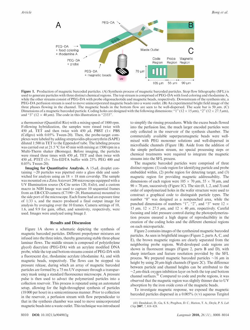
Figure 1A shows a schematic depicting the synthesis ofmagnetic barcoded particles. Different prepolymer mixtures areinfused into the three inlets, thereby generating stable three-phaselaminar flows. The middle stream is composed of poly(ethyleneglycol) diacrylate (PEG-DA) with an acrylate modified DNAprobe, while the top and bottom streams consist of PEG-DAwitha fluorescent dye, rhodamine acrylate (rhodamine A), and withmagnetic beads, respectively. The flows can be stopped viapressure release, during which an array of magnetic barcodedparticles are formed by a 75 msUV exposure through a transpar-ency mask using a standard fluorescence microscope. A pressurepulse is then used to advect the polymerized particles into acollection reservoir. This process is repeated using an automatedsetup, allowing for the high-throughput synthesis of particles(18 000 per hour) in a semicontinuous manner. Prior to collectionin the reservoir, a perfusion stream with flow perpendicular tothat in the synthesis chamber was used to move unincorporatedmagnetic beads into awaste outlet. This techniquewas introduced
to simplify the rinsing procedures. While the excess beads flowedinto the perfusion line, the much larger encoded particles wereonly collected in the reservoir of the synthesis chamber. Thecommercially available superparamagnetic beads were well-mixed with PEG monomer solutions and well-dispersed inmicrofluidic channels (Figure 1B). Aside from the addition ofthe simple perfusion stream, no special processing steps orchemical treatments were required to integrate the magneticstreams into the SFL process.
The magnetic barcoded particles were comprised of threedistinct regions: (1) code region for identifying particle and probeembedded within, (2) probe region for detecting target, and (3)magnetic region for providing magnetic addressability. Thedimensions of each region were 105 � 70 μm, 55 � 70 μm, and90� 70 μm, successively (Figure 1C). The size (0, 1, 2, and 3) andorder of unpolymerized holes in the wafer structure were used toconstruct a graphical code to distinguish particle types. Thenumber “0” was designed as a nonpunched area, while thepunched dimensions of numbers “1”, “2”, and “3” were 12 �15 μm, 12 � 27.5 μm, and 12 � 40 μm, respectively. Carefulfocusing and inlet pressure control during the photopolymeriza-tion process ensured a high degree of reproducibility in thecreation of the coding holes and the different chemical regionson each microparticle.
Figure 2 contains images of the synthesizedmagnetic barcodedparticles. As seen in brightfield images (Figure 2, parts A, C, andE), the brown magnetic regions are clearly separated from theneighboring probe regions. Well-developed code regions areshown in fluorescent images (Figure 2, parts B and D), withsharp interfaces and feature resolution provided by the SFLprocess. We prepared magnetic barcoded particles ∼16 μm inheight by using 20 μm-high channels (Figure 2C). The differencebetween particle and channel heights can be attributed to the∼2 μm-thick oxygen inhibition layer on both the top and bottomchannel surfaces.41 Compared to code and probe regions, it wasobserved that the magnetic region was slightly thinner due to UVabsorption by the iron oxide cores of the magnetic beads.
To investigate magnetic response, we exposed the magneticbarcoded particles dispersed in a 0.005% (v/v) aqueous Tergitol
Figure 1. Production of magnetic barcoded particles. (A) Synthesis process of magnetic barcoded particles. Stop flow lithography (SFL) isused to generate particles with three distinct chemical regions. The top stream is comprised of PEG-DAwith food coloring and rhodamineA,while the other streams consist of PEG-DAwith probe oligonucleotide andmagnetic beads, respectively. Downstream of the synthesis site, aPEG-DA perfusion stream is used tomove unincorporatedmagnetic beads into a waste outlet. (B) An experimental bright field image of thethree phases flowing in the channel. The magnetic beads in the bottom flow are seen to be well-dispersed. The scale bar is 50 μm. (C)Dimensions of amagnetic barcoded particle. Coding holes are designedwith the following dimensions: “1” (12� 15 μm), “2” (12� 27.5 μm),and “3” (12 � 40 μm). The code in this illustration is “2333”.
(41) Dendukuri, D.; Gu, S. S.; Pregibon, D. C.; Hatton, T. A.; Doyle, P. S. LabChip 2007, 7, 818–828.

DOI: 10.1021/la904903g 8011Langmuir 2010, 26(11), 8008–8014
Bong et al. Article
NP-10 solution in a PDMS reservoir to aweak homogeneous field(21.1 ( 0.1 mT) perpendicular to the reservoir substrate. Sus-pended in a nonmagnetic medium, the particles acquired dipolemoments and flipped up perpendicular to the plane, formingcolumnar structures along the applied field direction (Figure 3Aand Supporting Information). In the presence of a weak homo-geneous field (14.7 ( 0.1 mT) parallel to the substrate plane,attractive induced dipolar interactions lead to tail-to-tail self-assembly of the particles (Figure 3B).
The magnetic functionality can be used to orient and transportthe barcoded particles as shown in Figure 3C-E and SupportingInformation. Using a hand magnet, it was possible to remotelyand precisely manipulate the orientation of magnetic barcodedparticles at the inlet of a microfluidic channel to aspirate allparticles such that they proceeded down the analysis chamber ina “probe first” (versus “code first”) orientation. Figure 3C showsthe reorientation process of a barcoded particle from “code first”to “probe first” within a microfluidic channel. By moving a morepowerfulmagnet even closer to the channel, itwas possible to thentransport this reoriented particle from the inlet to a more narrowzone used for single-particle analysis (Figure 3D). Although thetransportation velocity was only 10 μm/s in this experiment, theprocess was performed in a simple manner using a commonmagnet. This pumpless method for orientation and movementdoes not require the complex setup used in pressure-drivenalignment processes and does not subject the soft hydrogelparticles to the significant hydrodynamic forces that pressure-driven processes can introduce in microchannels.42
This capacity to address the position and orientation ofindividual particles provides ameans for improving upon recentlydeveloped particle analysismethods. In particular, the fabrication
of a magnetic aspiration column could be used to deliver allparticles to a flow-through scanning chamber42 with the sameprobe-first orientation. As existing high-throughput flow align-ment methods cannot control which end of the particle leads inthe flow, decoding algorithms that determine probe identity andamount of bound target must additionally ascertain the orienta-tionof the particle for accurate analysis. This requires using one ofthe coding elements as an orientationmarker. If all particles couldbe magnetically addressed to give the same orientation prior toentrance into the flow chamber, this would no longer be necessaryand the coding capacity of thesemicroparticles could be expandedby a factor of 4. It should also be noted that the simultaneousreorientation and transportation of multiple barcoded particleswas achieved in a large reservoir using a hand magnet (Figure 3Eand Supporting Information). This capability could potentiallybe exploited for the ordered presentation of posthybridizationparticles in a plate-based stationary scan.
The magnetic functionality also introduces a new means bywhich the barcoded particles can be concentrated and subse-quently separated from a carrier solution. In previous implemen-tations of barcoded hydrogel particles for biomolecule detection,10 centrifugal separations were required for the rinsing steps in atypical assay. This density-based separation strategy tends toconcentrate fibers and other particulate matter along with theencoded microparticles at the bottom of the sample tube. If thesecontaminants then stick to the particles, they can interfere withthe analysis of the fluorescence emitted by the code and proberegions. Magnetic force separation provides an alternative ap-proach to segregating the barcoded particles for rinsing proce-dures. Using a permanent magnet, we successfully separated theparticles on the side of a collection tube in 2 min (Figure 3F). Infurther experiments, the 10 rinsing steps of a DNA hybridiza-tion assay were carried out using magnetic barcoded hydrogel
Figure 2. Magnetic barcoded particles. (A) Bright field image (20� objective) of magnetic barcoded particles with code “2333”. (B)Fluorescent image of particles in partA. (C) Side viewof amagnetic barcoded particle in a bright field image (20� objective). (D) Fluorescentimageofparticles inpartC. (E)Bright field image (5�objective) ofmagneticbarcodedparticleswith code“0013”. Scale bars are 50μm(AandB), 25 μm (C and D), and 100 μm (E).
(42) Chapin, S. C.; Pregibon, D. C.; Doyle, P. S. Lab Chip 2009, 9, 3100–3109.

8012 DOI: 10.1021/la904903g Langmuir 2010, 26(11), 8008–8014
Article Bong et al.
microparticles and onlymagnetic separation steps. Upon analysisof the particles, it was determined that the vast majority ofparticles had been retained and, furthermore, a considerablysmaller amount of particulate matter was seen in the carriersolution.
A wide variety of geometrically and chemically complexmagnetic barcoded particles can be prepared by SFL using simplemask replacements and inlet fluid exchanges. Table 1 summarizesthe four particle types used in a multiplexed DNA sensing study,illustrating the code, the identity of incorporated probe, and thepresence or absence of magnetic beads in the tail region. Types 1,2, and 3 featured a magnetic tail and were incorporated with noprobe (type 1), probe no. 1 (type 2), or probe no. 2 (type 3) in thecentral region. Type 4 featured a nonmagnetic tail, bore probeno. 1, andwas used to investigate the effect of the addedmagneticmaterial on target detection. If the magnetic region is indeed inertwith respect to target capture, the mean signals from the target
panels on types 2 and 4 should be the same when incubated withtarget corresponding to probe no. 1.
The four particle types were hybridized with either 0 or200 amol of two different biotinylated target oligonucleotides.Following hybridization and labeling with SAPE, the fluorescentimages of five particles of each type for each incubation conditionwere analyzed. An incubation matrix was prepared to comparethe performance of the various particles (Figure 4). Each plot inthe matrix represents the average signal of 5 scans of each particletype at the specified incubation condition. The mean fluorescentintensity across the width of the particle (vertical axis, AU) wascalculated and then plotted at each lengthwise position(horizontal axis, pixels) along the particle. The fluorescent in-tensities in the probe and tail regionswere crucial to evaluating thesuccess of the detection and examining the effect of the magneticregions. As illustrated by a comparison of the results from types 2and 4 in Figure 4, the mean signals in these regions are similarwhether the tail region is magnetic or nonmagnetic, indicatingthat themagneticmaterial does not interferewith the sensitive andspecific detection of the oligonucleotides.
It should be noted that target 1 generated a lower signal thantarget 2 when incubations were performed with all four typessimultaneously in a single Eppendorf tube. The lower signal fortarget 1 can be attributed to the presence of two particle types(2 and 4) bearing probe 1 in the incubation mixture. Because ofthis redundancy, target 1 was spread over∼100 total particles perincubation, whereas target 2 was spread over only ∼50 totalparticles per incubation. When the same amount of target 1
Figure 3. Response of magnetic barcoded particles. (A) Response of magnetic barcoded particles to out-of-plane (21.1( 0.1mT) magneticfield. (B) Response of magnetic barcoded particles to in-plane (14.7 ( 0.1mT) magnetic field. (C) Reorientation of a magnetic barcodedparticle in a microfluidic channel using a hand magnet. (D) Snapshots of magnetic transportation of a magnetic barcoded particle using ahandmagnet. The particle was transported toward a narrow region in themicrofluidic channel used for single-particle scanning analysis. (E)Image of reorientedmagnetic barcoded particles moving toward a handmagnet. (F) Bulk separation of magnetic barcoded particles using ahand magnet. Scale bars are 50 μm (C and D), 100 μm (A and B), and 200 μm (E).
Table 1. Design of the Four Different Magnetic Barcoded Particle
Types

DOI: 10.1021/la904903g 8013Langmuir 2010, 26(11), 8008–8014
Bong et al. Article
(200 amol) was incubated with ∼50 particles of type 4 (probe 1,nonmagnetic) alone, a signal (∼63.2 AU) as high as that seenwiththe particles bearing probe 2 in the earlier assays was observed,thus confirming that the particle density led to the disparity in theoriginal target levels (Supporting Information).
Conclusions
We have demonstrated that a modified form of SFL can beused to generate magnetic barcoded particles through the addi-tion of a monomer stream containing superparamagnetic beads,aswell as a perfusion rinse stream. The addedmagnetic region canacquire dipole moments in the presence of low-strength homo-geneous magnetic fields, allowing the particles to align along theapplied field direction. The magnetic barcoded particles haveexhibited an enhanced range of functionality, providing novelmeans for orientation and separation during biological assays.The magnetic region has no apparent negative effects on thesensitive and specific multiplexed sensing of oligonucleotidetargets. Although we have demonstrated the creation and use of
relatively simple magnetic barcoded particles, the flow litho-graphic process for loading magnetic materials described herecan perhaps be combined with more complex, multidimensionalsynthesis strategies such as lock release lithography (LRL)43 andhydrodynamic focusing lithography (HFL)44 to produce micro-particles with additional novel properties advantageous for self-assembly and biomolecule detection studies.
Acknowledgment. We gratefully acknowledge the support ofGrant R21EB008814 from the National Institute of BiomedicalImaging and Bioengineering, National Institutes of Health,Kwanjeong Educational Foundation, the MIT DeshpandeCenter, and the Singapore-MIT Alliance. We also thankDr. Ramin Haghgooie for kindly providing a SU-8 master,and Dr. Chunghee Nam and Dr. Youngman Jang for theirassistance with alternating gradient magnetometry.
Figure 4. Incubation matrix. Particles with a fluorescent code region, an internal probe region, and a tail region were synthesized andincubated with either 0 or 200 amol of two different biotinylated target oligonucleotides at 50 �C for 90 min. Following incubation, probe-target complexeswere labeledwith streptavidin-phycoerythrin (SAPE) at 21.5 �Cfor 45min.Particle type1 featurednoprobe, amagnetic tail,and code “2333”; type 2 featured probe 1, a magnetic tail, and code “2003”; type 3 featured probe 2, a magnetic tail, and code “0013”; type 4featured probe 1, a nonmagnetic tail, and code “2013”. Each plot shows the average of five scans of each particle type at the specifiedincubation condition. Horizontal axis is axial (lengthwise) position in pixels, and vertical axis is mean fluorescent intensity in arbitrary units.The mean signal across the width of the particle has been computed and plotted at each axial position. The red numbers above each scanindicate the mean fluorescent intensity measured in the probe region and in the tail region. The red bars in the first plot indicate the windowsover which the averages were taken. Quoted numbers represent the mean of five separate scans.
(43) Bong, K. W.; Pregibon, D. C.; Doyle, P. S. Lab Chip 2009, 9, 863–866.(44) Bong, K.W.; Bong, K. T.; Pregibon, D. C.; Doyle, P. S.Angew. Chem., Int.
Ed. 2010, 49, 87–90.

8014 DOI: 10.1021/la904903g Langmuir 2010, 26(11), 8008–8014
Article Bong et al.
Supporting Information Available: Figures showing AGMmagnetization curves for the beads and themagnetic regions ofbarcodedparticles andparticle scans for additional incubationsto investigate effect of particle density. Movie demonstratingthat the magnetic barcoded hydrogel particles flip up when a
magnetic field perpendicular to the substrate is applied andmovie showing that the multiple barcoded particles can besimultaneously reoriented and transported in a large reservoirusing a hand magnet. This material is available free of chargevia the Internet at http://pubs.acs.org.