kinect: the next generation of motion control - unictbattiato/cvision1112/kinect.pdfkinect: the next...
TRANSCRIPT


Overview
• Introduction • IpLab Projects • Technology
– The Kinect Sensor – The Kinect Features
• Applications • Depth Map
– Time-of-Flight (ToF) • Pulsed Modulation • Continuous Wave Modulation
– Light coding
• Real time human tracking • RGB-D 3D-Mapping
Introduction (1)
• Kinect was launched in North America on 4 November 2010
• Kinect has changed the way people play games and experience entertainment
• Kinect offers the potential to transform how people interact with computers and Windows-embedded devices in multiple industries: – Education – Healthcare – Transportation – Game

Introduction(2)
• Kinect is a motion sensing input device • Is used for:
– Xbox 360 console – Windows PCs
• Enables users to control and interact with the application/game – Without the need to touch a game controller – Through a natural user interface – Using gestures and spoken commands
• Kinect competes with the: – Wii Remote Plus – PlayStation Move – PlayStation Eye motion

Technology
• Software is developed by Rare
• Camera technology is developed by Israeli PrimeSense
– Interpret specific gestures
– Making completely hands-free control of devices
– 3D scanner system called Light Coding • Special microchip to track the movement of objects and
individuals in three dimension.
• Employs a variant of image-based 3D reconstruction

The Kinect System (1)
• Horizontal bar connected to a small base
• Motorized pivot • Designed to be positioned
lengthwise above or below the video display
• Consist of: – An Infrared projector – A color camera – An Infrared sensor – Multi-array microphone that enables
to: • Acoustic source localization • Ambient noise suppression

The Kinect System (2) http://www.youtube.com/watch?v=6CFoOFZ6ifc Kinect filmed with a night vision camera - HD

Camera characteristics (1)
• The depth sensor captures video data in 3D under any ambient light conditions – Infrared laser projector – Monochrome CMOS sensor
• The Kinect software is capable of automatically calibration:
– Based on gameplay – Based on physical environment – Accommodating for the presence of furniture or other obstacles
• Kinect is capable of:
– Tracking up to six people – Performing motion analysis for two active players – Feature extraction of 20 joints per player

Camera characteristics (2)
• The Kinect sensor outputs the video at a frame rate of 30 Hz.
• The RGB video stream uses 8-bit VGA resolution (640 × 480 pixels) with a Bayer color filter
• The monochrome depth sensing video stream is in VGA resolution (640 × 480 pixels) with 11-bit depth.
• The Kinect has a practical ranging limit: – 1.2m –3.5 m Kinect for Xbox 360 – 40cm–3.5 m Kinect for Windows

Kinect for windows
• Launched In February 2012
• New features provided: – Near Mode
• Enables the depth camera to see objects as close as 40 cm
– Skeletal tracking enhancement
– Advanced speech and audio capabilities
– Improved synchronization between color and depth, mapping depth to color, and a full frame API
– API improvements enhances consistency and ease of development

Kinect Features
1. Full-body 3D motion capture
2. Gesture recognition
3. Facial recognition
4. Voice recognition capabilities

Applications
1. IPLab 2. Virtual Dressing Room 3. Interactive Training 4. Merges Real and Virtual Worlds 5. Kinect in Hospitals 6. Kinect Quadrocopter 7. DepthJS 8. The Flying Machine 9. Virtual Piano

IPLAB & Kinect
• Usage of the Kinect System for homework and student's projects – (Computer Vision course - Prof. S. Battiato - University of Catania)
• 2 Research projects: 1. POR4.1.1.2 EMOCUBE (EdisonWeb) 2. POR4.1.1.1 DIGINTEGRA (EdisonWeb, CCR,…) – Analyze the feedback of audiovisual advertising – Integrate of interactive multimedia content through natural interface
Virtual Dressing Room
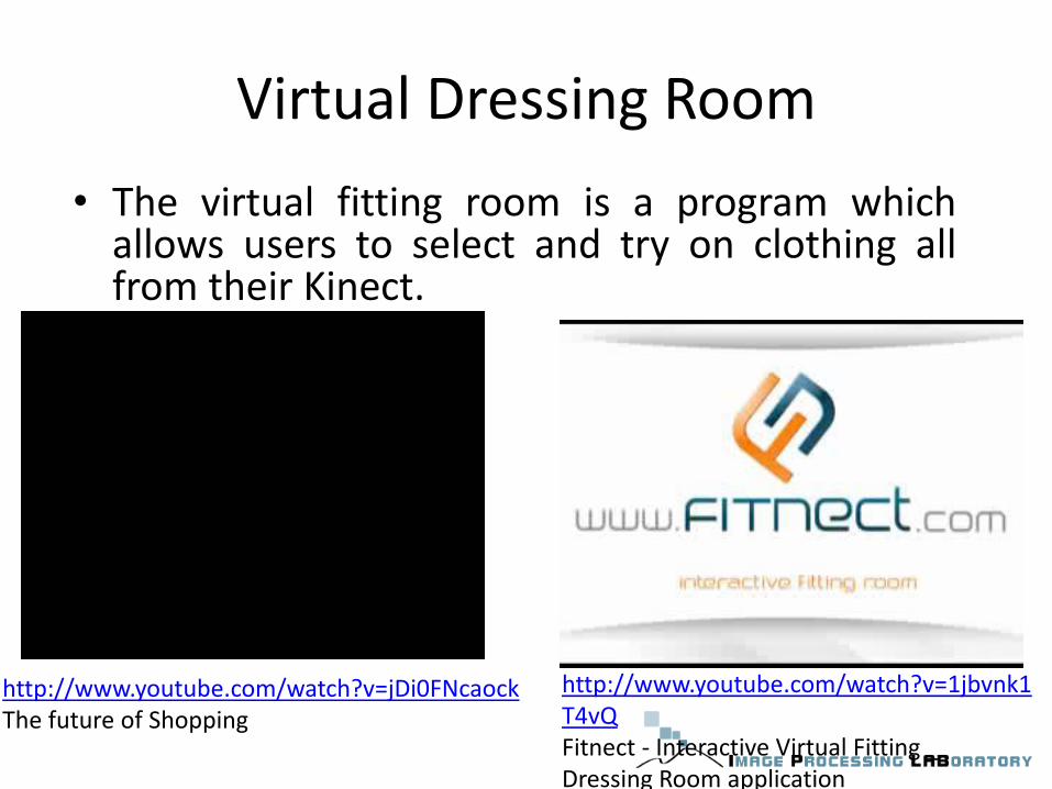
• The virtual fitting room is a program which allows users to select and try on clothing all from their Kinect.
http://www.youtube.com/watch?v=jDi0FNcaock The future of Shopping
http://www.youtube.com/watch?v=1jbvnk1T4vQ Fitnect - Interactive Virtual Fitting _ Dressing Room application

Interactive Training
• Mini-VREM used the Kinect to create a system which tracks users' hand position, placement, and rate and strength of compressions to teach them how to correctly perform CRP

KinectFusion: Merges Real and Virtual Worlds
• Generate three-dimensional (3D) models in real time using a standard Kinect system.
• The technology can scan in 3D: – Objects – People – Entire rooms

Kinect in Hospitals
• Kinect also shows compelling potential for use in medicine • Kinect for intraoperative, review of medical imaging,
allowing the surgeon to access the information without contamination

Kinect Quadrocopter
• The Kinect flying quadrocopter is controlled using hand gestures
http://www.youtube.com/watch?v=A52FqfOi0Ek Interaction with a Quadrotor via the Kinect, ETH Zurich
DepthJS
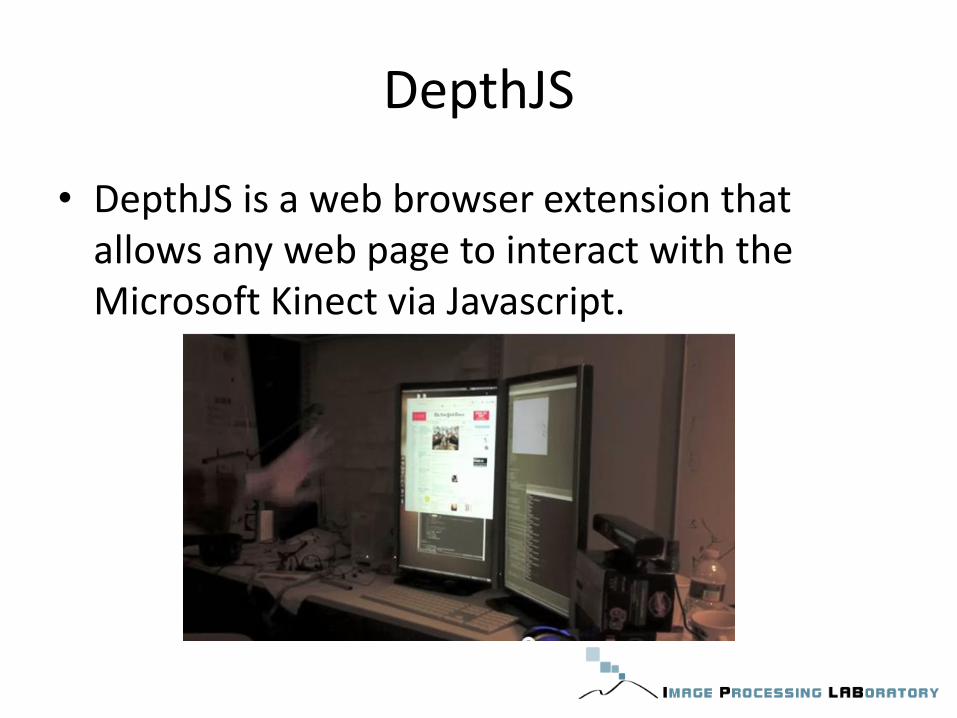
• DepthJS is a web browser extension that allows any web page to interact with the Microsoft Kinect via Javascript.
The Flying Machine
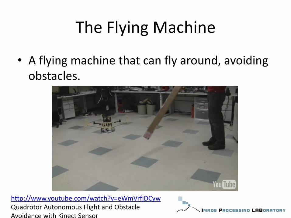
• A flying machine that can fly around, avoiding obstacles.
http://www.youtube.com/watch?v=eWmVrfjDCyw Quadrotor Autonomous Flight and Obstacle Avoidance with Kinect Sensor

Virtual Piano
• Users can play a virtual piano by tapping their fingers on an empty desk
http://www.youtube.com/watch?v=4STUGl-YHDc E3 2011- Kinect Fun Labs Election- Keyboard Anywhere

Depth Map
[2] R. Lange. 3D time-of-flight distance measurement with custom solid-state image sensors in CMOS/CCD-technology. Diss., University of Siegen, 2000 [4]V. Ganapathi, C. Plagemann, D. Koller, S. Thrun: Real-time motion capture using a single Time-of-flight camera. IEEE Conference on Computer Vision and Pattern Recognition (CVPR), 2010

Classification of Depth Measurement Techniques
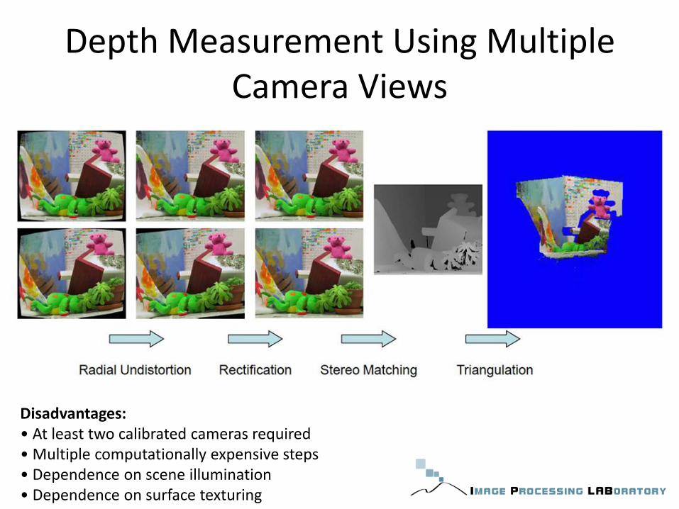
Depth Measurement Using Multiple Camera Views
Disadvantages: • At least two calibrated cameras required • Multiple computationally expensive steps • Dependence on scene illumination • Dependence on surface texturing

Time-of-Flight (ToF) • Perform the depth quantifying the changes that
an emitted light signal encounters when it bounces back from objects in a scene

Time-of-Flight (ToF)
Advantages: • Only one camera required • Acquisition of 3D scene geometry in real-time • Reduced dependence on scene illumination • Almost no dependence on surface texturing

Principles of ToF Imaging: Pulsed Modulation (1)
• Measure distance to a 3D object by measuring the absolute time a light pulse needs to travel from a source into the 3D scene and back, after reflection:
– Speed of light is constant and known: c = 3·10^8 m/s

Principles of ToF Imaging: Pulsed Modulation (2)
• Advantages: – Direct measurement of time-of-flight
– High-energy light pulses limit influence of background illumunation
• Disadvantages: – High-accuracy time measurement required
– Measurement of light pulse return is inexact, due to light scattering
– Difficulty to generate short light pulses with fast rise and fall times

Principles of ToF Imaging: Continuous Wave Modulation (1)
• Continuous light waves instead of short light pulses • Modulation in terms of frequency of sinusoidal waves • Detected wave after reflection has shifted phase • Phase shift proportional to distance from reflecting
surface

Principles of ToF Imaging: Continuous Wave Modulation (2)
• Retrieve phase shift by demodulation of received signal
• Demodulation by cross-correlation of received signal with emitted signal
• Emitted sinusoidal signal:
• Received signal after reflection from 3D surface:
• Cross-correlation of both signals:
: modulation frequency b: constant bias a: amplitude : phase shift :offset

Principles of ToF Imaging: Continuous Wave Modulation (3)
• Cross-correlation function simplifies to:
• Sample c() at four sequential instants with different phase offset :
• Directly obtain sought parameters:
b:constant bias a: amplitude : phase shift : internal offset

Principles of ToF Imaging: Continuous Wave Modulation (4)
• The summation of each sample over several modulation periods increases the signal-to-noise ratio.

Principles of ToF Imaging: Continuous Wave Modulation (5)
• Advantages: – Variety of light sources available as no short/strong
pulses required – Applicable to different modulation techniques (other
than frequency) – Simultaneous range and amplitude images
• Disadvantages: – In practice, integration over time required to reduce
noise – Frame rates limited by integration time – Motion blur caused by long integration time

Computer Vision with ToF Cameras Measurement Errors and Noise
Systematic distance error
• Perfect sinusoidal signals hard to achive in practice
Intensity-related distance error
• Computed distance depending on amount of incident light

Structured Light
• Patterns of light are projected onto an object: – Grids – Stripes – Elliptical patterns
• Surface shapes are deduced from the distortions of the patterns that are produced on surface of the object.
• With knowledge of relevant camera and projector geometry, depth can be calculated by triangulation
• The challenge in optical triangulation is obtaining correspondence between points in the projected pattern and pixels in the image
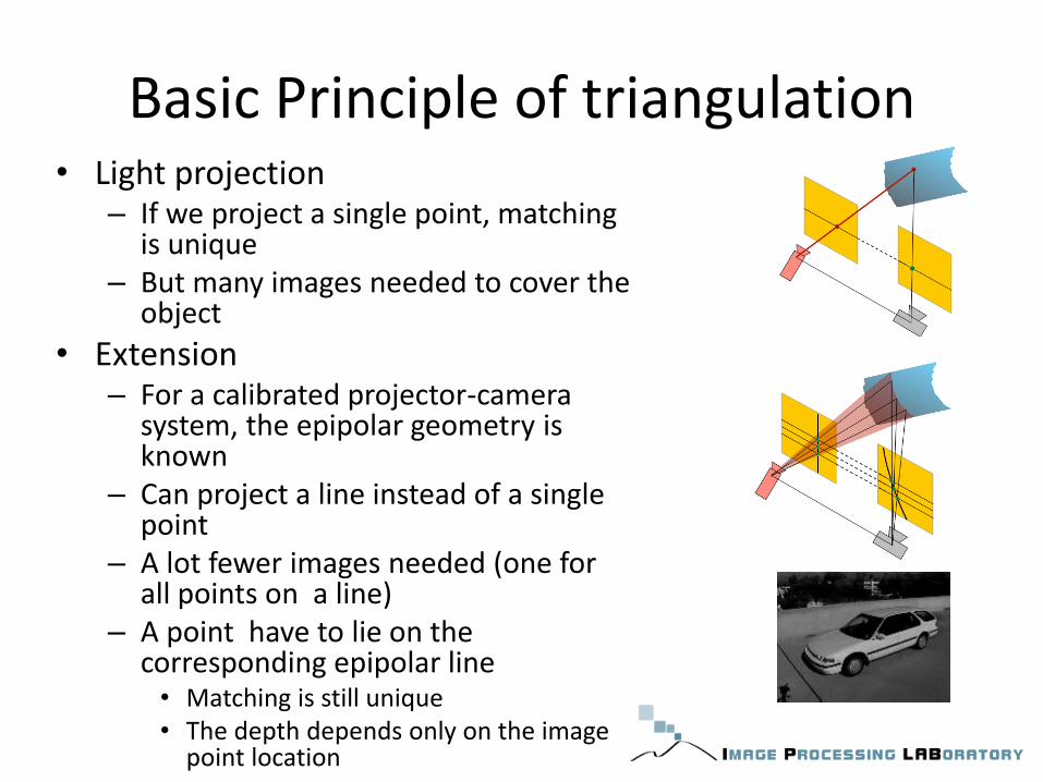
Basic Principle of triangulation • Light projection
– If we project a single point, matching is unique
– But many images needed to cover the object
• Extension – For a calibrated projector-camera
system, the epipolar geometry is known
– Can project a line instead of a single point
– A lot fewer images needed (one for all points on a line)
– A point have to lie on the corresponding epipolar line • Matching is still unique • The depth depends only on the image
point location

Pattern projection
• Project a pattern instead of a single point or line
• Needs only a single image, one-shot recording
• The correspondence between observed edges and projected image is not directly measurable – The matching is no
unique

How calculate the depth data?
• For a calibrated projector-camera system the 2D correspondence is reduced in purely horizontal matching (one dimensional) – Determining correspondences
between each row of the projected pattern and a row of the rectified camera image
– The relative distance between a point in the illumination pattern and its position in the captured image is inversely related to depth
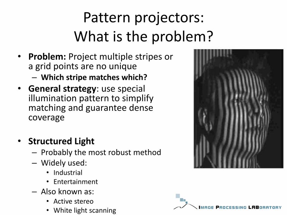
Pattern projectors: What is the problem?
• Problem: Project multiple stripes or a grid points are no unique – Which stripe matches which?
• General strategy: use special illumination pattern to simplify matching and guarantee dense coverage
• Structured Light – Probably the most robust method – Widely used:
• Industrial • Entertainment
– Also known as: • Active stereo • White light scanning

Pattern projectors Multi-stripe Projectors
Time-coded light patterns – “Best compromise” between single stripes and stripe
pattern
– Use a sequence of binary patterns → log (images_width)
– Each stripe has a unique binary illumiation code

Pattern projectors: Coloured stripes
• Can be designed such that local patterns are unambiguous
• Difficult to use for coloured surfaces

Breast Shape Analysis for Objective Surgical Outcome Evaluation (2005)
INT: Istituto Nazionale per lo studio e la cura dei Tumori Milano

Pattern projectors Pseudo random pattern
• Spatial Neighborhood: The codeword that labels each pixel is obtained from a neighborhood of pixels around it. – This coding has to be unique per position in order to recognize each point
in the pattern. – The decoding stage is more difficult because the whole neighborhood can
not always be recovered due to occlusions and shadows – Used In the Kinect System

Principles of Kinect (1)
• Projects a known pattern (Speckles) in Near-Infrared light.
• CMOS IR camera observes the scene.
• Calibration between the projector and camera has to be known.
• Triangulation of each speckle between a virtual image (pattern) and observed pattern
Principles of Kinect (2)
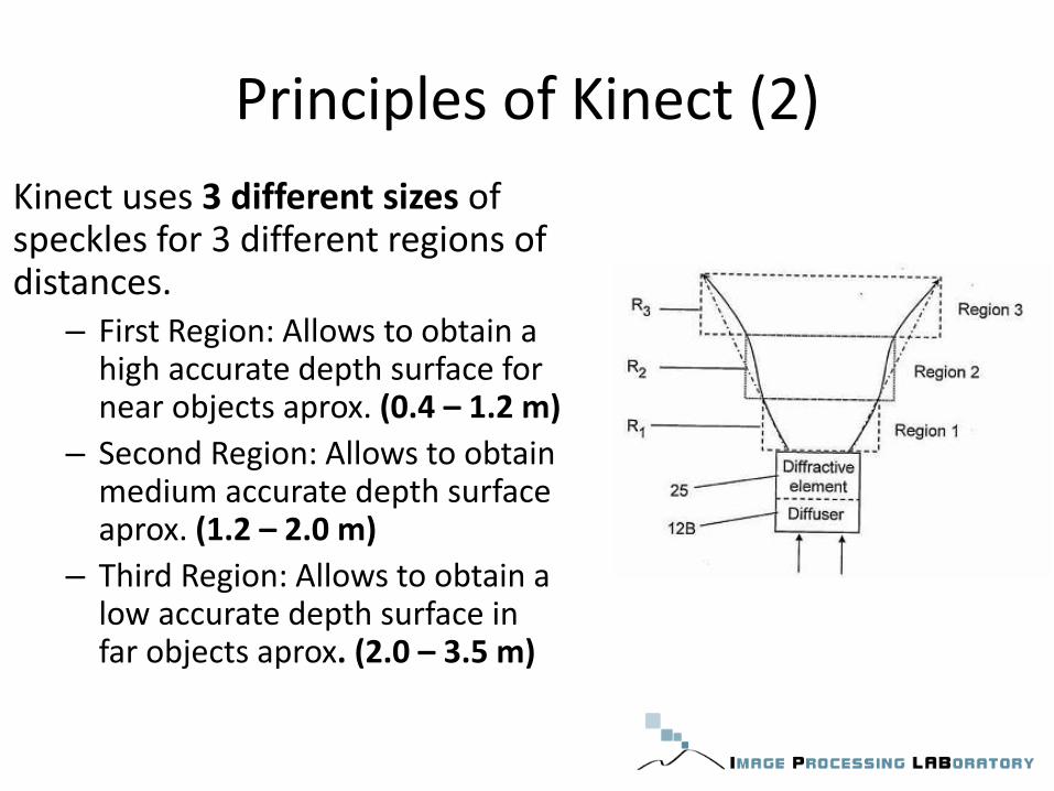
Kinect uses 3 different sizes of speckles for 3 different regions of distances.
– First Region: Allows to obtain a high accurate depth surface for near objects aprox. (0.4 – 1.2 m)
– Second Region: Allows to obtain medium accurate depth surface aprox. (1.2 – 2.0 m)
– Third Region: Allows to obtain a low accurate depth surface in far objects aprox. (2.0 – 3.5 m)

Real time human tracking
[1]Real-time Human Pose Recognition in Parts from Single Depth Images. Jamie Shotton, et.al,
CVPR 2011. [2] Efficient Regression of General-Activity Human Poses from Depth Images Ross Girshick, Jamie Shotton, Pushmeet Kohli, Antonio Criminisi, and Andrew Fitzgibbon October 2011
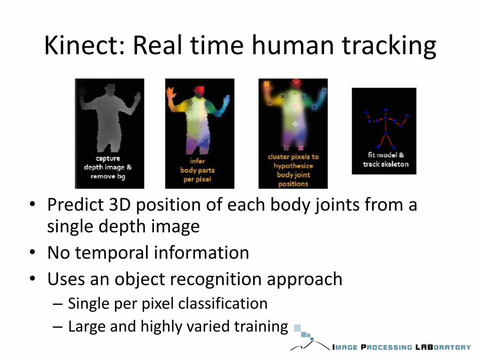
Kinect: Real time human tracking
• Predict 3D position of each body joints from a single depth image
• No temporal information
• Uses an object recognition approach – Single per pixel classification
– Large and highly varied training
Kinect: Real time human tracking
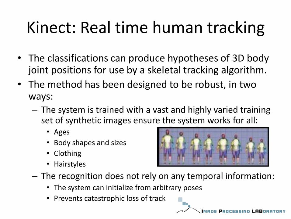
• The classifications can produce hypotheses of 3D body joint positions for use by a skeletal tracking algorithm.
• The method has been designed to be robust, in two ways: – The system is trained with a vast and highly varied training
set of synthetic images ensure the system works for all: • Ages
• Body shapes and sizes
• Clothing
• Hairstyles
– The recognition does not rely on any temporal information: • The system can initialize from arbitrary poses
• Prevents catastrophic loss of track

Database

Features
= depth at pixel x
Ensure the features are depth invariant
• Feature θ1 give: – a large positive response for pixel near the top of the body – a value close to zero for pixel lower down the body
• Feature θ2: – help to find vertical structure such as the arm

Random Decision Forest
• This features provide only a weak signal about which part of the body the pixel belong to
• Combining this features in a decision forest they are sufficient to train all body parts
= Distribution of pixel x over labels c

Random Decision Forest

Training Decision Forest
• Randomly select a set of (, ) – features
– thresholding
• Split training examples by each split
• Choose the split with maximum information gain
• Move into next layer
• 3 trees to depth 20 from 1 million images – 1 day training on 1000 cores

Results of pixels classification

Find the joints
Mean-shift is used to find the mods (joints) in a density estimator per body part
Where: • 𝒙 is a coordinate in 3D world space • N is the number of image pixels • Wic is a pixel weighting • 𝒙𝒊 is the reprojection of image pixel xi into world
space given depth • bc is a learned per-part bandwidth
Inferred body part probability at the pixel
For depth Invariant considering surface area
Speed
• Estimating this pixel-wise classification is extremely efficient: – Each pixel can be processed in parallel on the GPU – Each feature computation:
• read 3 image pixels • 5 arithmetic operations
• Decision forest: – Fast computing – Can be parallel between trees
• 200 Frame per second on consumer hardware

RGB-D Mapping for 3D Modeling of Indoor
Environments
[5]RGB-D Mapping: Using depth cameras for dense 3D modeling of indoor environments. Henry, Krainin, Herbst, Ren, Fox. ISER 2010.

RGB-D Mapping
• Build dance 3D maps of indoor environments
• Important task for robot navigation

System Overview
• Three main components – Spatial alignment of consecutive data frames
– Detect of loop closures
– Globally consistent alignment of the complete data sequence

RGB-D Features
• Points clouds: – Are well suited for frame to
frame alignment – Ignore valuable visual
information contained in the image
– Sparse • Visual features (from image)
in 3D (from depth)
– Dense • Points in the depth maps
• Color cameras: – Capture rich visual
information
Sparse 3D points clouds
Dense 3D points clouds

Frame-to-frame alignment: RGBD-ICP
• Problem: features extraction in Low light – Lack of visual “texture” or features
• Solution: – Using RANSAC for sparse point features – Using ICP “Iterative closest point” for dance point cloud

Frame-to-frame alignment: RGBD-ICP • RANSAC
– SIFT matching • For each feature point, find the most similar descriptor in the other frame
– Find largest set of consistent matches
• Iterative closest point (ICP) – The points in a source cloud Ps are matched with they nearest
neighboring points in a target cloud Pt – Rigid transformation is found by minimizing the error between
associate point
Loop closure problem
• Alignment between successive frames is a good method for tracking the camera position over moderate distances.
• Estimation of camera position over long distances, make inaccuracies in the map. – The causes are:
• Errors in alignment between a particular pair of frames • Noise • Quantization in depth values
– The cumulative error in frame alignment results in a map that has two representations of the same region in different locations
– The map must be corrected to merge duplicate regions

Loop closure detection • Solution:
– Loop closure detections to recognize when the camera has returned to a previously visited location
– The map must be correct to merge duplicate regions
• The strategy is to represent constraints between frames with a graph structure – The relative transformations from the alignment of
sequential frames give us some constraints.
– Loop closures are represented as constraints between frames that are not temporally adjacent.
– KeyFremas are defined to keep the graph relatively sparse

Global Alignment
• A parallel loop closure detection thread uses the sparse feature points to match the current frame against previous observations, taking spatial constraints into account.
• If a loop closure is detected, a constraint is added to the pose graph and a global alignment process is triggered.

References
• [1]Real-time Human Pose Recognition in Parts from Single Depth Images. Jamie Shotton, et.al, CVPR 2011.
• [2] R. Lange. 3D time-of-flight distance measurement with custom solid-state image sensors in CMOS/CCD-technology.
• Diss., University of Siegen, 2000
• [3]Microsoft Kinect. http://www.xbox.com/de-de/kinect
• [4]V. Ganapathi, C. Plagemann, D. Koller, S. Thrun: Real-time motion capture using a single Time-of-flight camera. IEEE Conference on Computer Vision and Pattern Recognition (CVPR), 2010
• [5]RGB-D Mapping: Using depth cameras for dense 3D modeling of indoor environments. Henry, Krainin, Herbst, Ren, Fox. ISER 2010.