kinematic and kinetostatic synthesis of planar coupled ...suresh/journal/j18krovi3jmd2002.pdf ·...
TRANSCRIPT
l classfor ardwareains, weplanartionson tolectedong averalnal
en-esis of
Downlo
Venkat Krovi†
e-mail: [email protected]
G. K. Ananthasureshe-mail: [email protected]
Vijay Kumare-mail: [email protected]
Mechanical Engineering and Applied Mechanics,University of Pennsylvania,
Room 301C, GRASP Lab,3401 Walnut Street,
Philadelphia, PA 19104
Kinematic and KinetostaticSynthesis of Planar CoupledSerial Chain MechanismsSingle Degree-of-freedom Coupled Serial Chain (SDCSC) mechanisms form a noveof modular and compact mechanisms with a single degree-of-freedom, suitablenumber of manipulation tasks. Such SDCSC mechanisms take advantage of the haconstraints between the articulations of a serial-chain linkage, created using gear-tror belt/pulley drives, to guide the end-effector motions and forces. In this paperexamine the dimensional synthesis of such SDCSC mechanisms to perform desiredmanipulation tasks, taking into account task specifications on both end-effector moand forces. Our solution approach combines precision point synthesis with optimizatirealize optimal mechanisms, which satisfy the design specifications exactly at the seprecision points and approximate them in the least-squares sense elsewhere alspecified trajectory. The designed mechanisms can guide a rigid body through sepositions while supporting arbitrarily specified external loads. Furthermore, torsiosprings are added at the joints to reduce the overall actuation requirements and tohance the task performance. Examples from the kinematic and the kinetostatic synthplanar SDCSC mechanisms are presented to highlight the benefits.@DOI: 10.1115/1.1464563#
i
l
i
p
r
t
e
i
e
es
cou-r tosndu-ins.ectorin-
singin
nalde-
ta--ted
dre-ndks.a-
gicederd inion
CSCtur-r toignralths,
ipu-tualtheility
re-
1 IntroductionTypical manipulation tasks require specification of the mot
of the manipulated object as well as its force interactions withenvironment. Further, many such tasks are inherently sindegree-of-freedom~d.o.f.!, parameterizable by a single variabsuch as the arc-length parameter. Hence, we introduce a nconfiguration calledSingle Degree-of-freedom Coupled SerChain ~SDCSC! mechanisms for executing such single degree-freedom manipulation tasks.
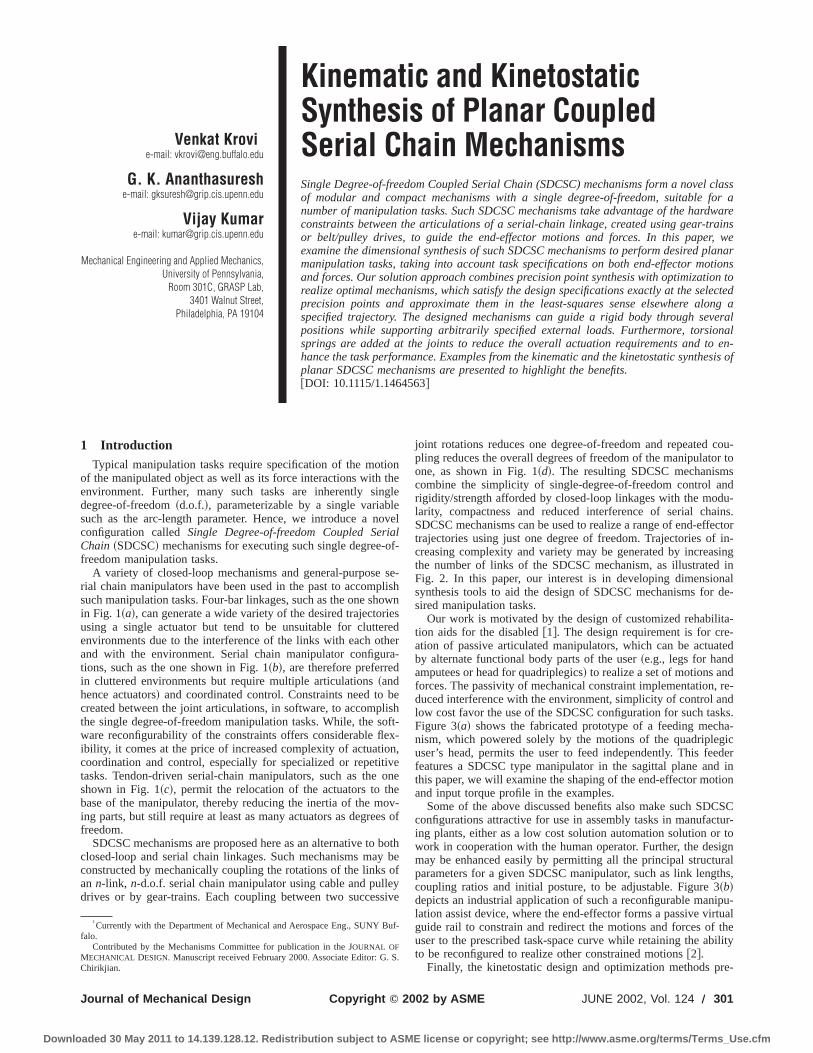
A variety of closed-loop mechanisms and general-purposerial chain manipulators have been used in the past to accomsuch manipulation tasks. Four-bar linkages, such as the one shin Fig. 1~a!, can generate a wide variety of the desired trajectousing a single actuator but tend to be unsuitable for clutteenvironments due to the interference of the links with each oand with the environment. Serial chain manipulator configutions, such as the one shown in Fig. 1~b!, are therefore preferredin cluttered environments but require multiple articulations~andhence actuators! and coordinated control. Constraints need tocreated between the joint articulations, in software, to accompthe single degree-of-freedom manipulation tasks. While, the sware reconfigurability of the constraints offers considerable flibility, it comes at the price of increased complexity of actuatiocoordination and control, especially for specialized or repetittasks. Tendon-driven serial-chain manipulators, such as theshown in Fig. 1~c!, permit the relocation of the actuators to thbase of the manipulator, thereby reducing the inertia of the ming parts, but still require at least as many actuators as degrefreedom.
SDCSC mechanisms are proposed here as an alternative toclosed-loop and serial chain linkages. Such mechanisms maconstructed by mechanically coupling the rotations of the linksan n-link, n-d.o.f. serial chain manipulator using cable and pulldrives or by gear-trains. Each coupling between two succes
†Currently with the Department of Mechanical and Aerospace Eng., SUNY Bfalo.
Contributed by the Mechanisms Committee for publication in the JOURNAL OFMECHANICAL DESIGN. Manuscript received February 2000. Associate Editor: G.Chirikjian.
Copyright © 2Journal of Mechanical Design
aded 30 May 2011 to 14.139.128.12. Redistribution subject to ASME li
onthegleeovelalof-
se-lishowniesredherra-
belishoft-x-n,veoneeov-s of
bothy beofyive
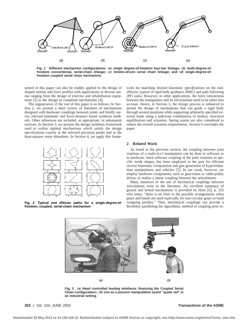
joint rotations reduces one degree-of-freedom and repeatedpling reduces the overall degrees of freedom of the manipulatoone, as shown in Fig. 1~d!. The resulting SDCSC mechanismcombine the simplicity of single-degree-of-freedom control arigidity/strength afforded by closed-loop linkages with the modlarity, compactness and reduced interference of serial chaSDCSC mechanisms can be used to realize a range of end-efftrajectories using just one degree of freedom. Trajectories ofcreasing complexity and variety may be generated by increathe number of links of the SDCSC mechanism, as illustratedFig. 2. In this paper, our interest is in developing dimensiosynthesis tools to aid the design of SDCSC mechanisms forsired manipulation tasks.
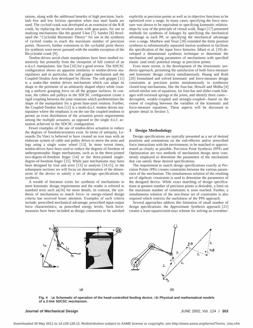
Our work is motivated by the design of customized rehabilition aids for the disabled@1#. The design requirement is for creation of passive articulated manipulators, which can be actuaby alternate functional body parts of the user~e.g., legs for handamputees or head for quadriplegics! to realize a set of motions anforces. The passivity of mechanical constraint implementation,duced interference with the environment, simplicity of control alow cost favor the use of the SDCSC configuration for such tasFigure 3~a! shows the fabricated prototype of a feeding mechnism, which powered solely by the motions of the quadripleuser’s head, permits the user to feed independently. This fefeatures a SDCSC type manipulator in the sagittal plane anthis paper, we will examine the shaping of the end-effector motand input torque profile in the examples.
Some of the above discussed benefits also make such SDconfigurations attractive for use in assembly tasks in manufacing plants, either as a low cost solution automation solution owork in cooperation with the human operator. Further, the desmay be enhanced easily by permitting all the principal structuparameters for a given SDCSC manipulator, such as link lengcoupling ratios and initial posture, to be adjustable. Figure 3~b!depicts an industrial application of such a reconfigurable manlation assist device, where the end-effector forms a passive virguide rail to constrain and redirect the motions and forces ofuser to the prescribed task-space curve while retaining the abto be reconfigured to realize other constrained motions@2#.
Finally, the kinetostatic design and optimization methods p
uf-
S.
002 by ASME JUNE 2002, Vol. 124 Õ 301
cense or copyright; see http://www.asme.org/terms/Terms_Use.cfm
302 Õ
Downloaded 30
Fig. 1 Different mechanism configurations: „a… single degree-of-freedom four-bar linkage; „b… multi-degree-of-freedom conventional, serial-chain linkage; „c… tendon-driven serial chain linkage; and „d… single-degree-of-freedom coupled serial chain mechanism.
n
u
e
s
qw
a
nsintod to
odyex-rald tos the
intor
pe-ientun-
ulley
eenof
henband
a-
sented in this paper can also be readily applied to the desigshaped motion and force profiles with applications in diverse anas ranging from the design of exercise and rehabilitation eqment @3# to the design of compliant mechanisms@4#.
The organization of the rest of this paper is as follows: In Stion 2, we present a short review of literature of mechanisdesigned with hardware couplings between joints and brieflyvey relevant kinematic and force-measure based synthesis mods. Other references are included, as appropriate, in subsesections. In Section 3, we present the design synthesis frameused to realize optimal mechanisms which satisfy the desspecifications exactly at the selected precision points and inleast-squares sense elsewhere. In Section 4, we apply this fr
Fig. 2 Typical end effector paths for a single-degree-of-freedom, coupled, serial-chain mechanism
Vol. 124, JUNE 2002
May 2011 to 14.139.128.12. Redistribution subject to ASME li
ofre-ip-
c-msur-eth-uentork
igntheme-
work for matching desiredkinematic specificationson the end-effector, typical of rigid body guidance~RBG! and path following~PF! tasks. However, in other applications, the force interactiobetween the manipulator and its environment need to be takenaccount. Hence, in Section 5, the design process is enhancepermit the design of mechanisms that can guide a rigid bthrough several positions while supporting arbitrarily specifiedternal loads using a judicious combination of motion, structuequilibration and actuation. Spring assists are also considerereduce the overall actuation requirements. Section 6 concludepaper.
2 Related WorkAs noted in the previous section, the coupling between jo
rotations of a multi-d.o.f manipulator can be done in softwarein hardware. Such software coupling of the joint rotations to scific mode shapes, has been employed in the past for efficinverse kinematic computation and gait generation of hyperreddant manipulators and vehicles@5#. In our work, however, weemploy hardware components, such as gear-trains or cable-pdrives, to realize a linear coupling between the articulations.
Many instances of the use of mechanical couplings betwarticulations exist in the literature. An excellent summarygeared and belted mechanisms is provided by Hunt@6#, p. 235who states ‘‘there is no limit to the possible arrangements wgears and bands are used especially for non-circular gears orwrapping profiles.’’ Thus, mechanical couplings can provideflexibility paralleling the algorithmic method of coupling joint ro
Fig. 3 „a… Head controlled feeding telethesis „featuring the Coupled SerialChain configuration …. „b… Use as a passive manipulation assist ‘‘guide rail’’ inan industrial setting.
Transactions of the ASME
cense or copyright; see http://www.asme.org/terms/Terms_Use.cfm
c
siof
teo
h-n
.
,
n-
s
t
beea-
on-
icaltage
tate
theified
reothignize
nk-s—thendd in
iredibedxi-
m-ism
re-m-
ltingrs ofca-
t onr, also
r of
eter-
Downlo
tations, along with the additional benefits of high precision, balash free and low friction operation when taut steel bandsused. The cycloid crank was developed as an extension of thecrank, by replacing the revolute joints with gear-pairs, for usestudying mechanisms like the geared 5-bar@7#. Sandor@8# devel-oped the ‘‘Cycloidal Burmester Theory’’ for use in the syntheof cycloid cranks to reach the maximum number of precispoints. However, further extensions to the cycloidal point thefor synthesis were never pursued with the notable exception oBicycloidal crank@9#.
Tendon-driven serial-chain manipulators have been studiedtensively but primarily from the viewpoint of full control of ann-d.o.f. manipulator. See Tsai@10# for a good review. The SDCSCconfiguration shows an apparent similarity to tendon-driven mnipulators and in particular, the soft gripper mechanism andCoupled-Tendon Arm developed by Hirose. The soft gripper@11#is a snake-like tendon driven mechanism which can adapshape to the perimeter of an arbitrarily shaped object while cring a uniform grasping force on all the gripper surfaces. In ctrast, the cables and pulleys in the SDCSC configuration crearigid coupling between the joint rotations which predeterminesshape of the manipulator for a given base-joint rotation. Furtthe Coupled-Tendon Arm@12# is a multi-d.o.f. tendon driven manipulator where the emphasis is on the use the coupled tendopermit an even distribution of the actuation power requiremeamong the multiple actuators, as opposed to the single d.o.ftuation achieved in the SDCSC configuration.
Fewer examples of the use of tendon-drive actuation to redthe degrees of freedom/actuators exist. In terms of antiquity,onardo Da Vinci is believed to have created an iron man withelaborate system of cable and pulley drives to move the armslegs using a single water wheel@13#. In more recent timestendon-drives have been used to reduce the degrees of freedoanthropomorphic finger mechanisms, such as in the three-joitwo-degree-of-freedom finger@14# or the three-jointed singledegree-of-freedom finger@15#. While past mechanisms may havbeen designed by trial and error@13# or analysis@14,15#, in thesubsequent sections we will focus on determination of the dimsions of the device to satisfy a set of design specificationssynthesis.
A wealth of literature exists for synthesis of mechanismsmeet kinematic design requirements and the reader is referrestandard texts such as@16# for more details. In contrast, the synthesis of mechanisms to match force- or energy-related decriteria has received lesser attention. Examples of such critinclude: prescribed mechanical advantage; prescribed input-ouforce characteristics; as prescribed energy levels. Such fomeasures have been included as design constraints to be sa
Journal of Mechanical Design
aded 30 May 2011 to 14.139.128.12. Redistribution subject to ASME li
k-areR-Rin
isonrythe
ex-
a-the
itsat-n-te atheer,
s tontsac-
uceLe-anand
m ofted
e
en-by
tod to-ign
eriatputrce-isfied
explicitly at precision points as well as in objective functions tooptimized over a range. In many cases, specifying the force msure was shown to be equivalent to specifying kinematic relatiships by way of the principle of virtual work. Bagci@17# presentedmethods for synthesis of linkages by specifying the mechanadvantage at each PP, or specifying the mechanical advanover a range. Matthew and Tesar@18# extended the finite positionsynthesis to infinitesimally separated motion synthesis to facilithe specification of the input force histories. Idlani et al.@19# de-veloped a dimensional synthesis technique to determinemechanism and spring parameters of mechanisms with specelastic~and total! potential energy at precision points.
Even more recent, is the development of thekinetostatic syn-thesis approach, permitting the satisfaction of both force-measuand kinematic design criteria simultaneously. Huang and R@20# formulated and solved kinematic and force-measure desconstraints at precision points simultaneously to synthesclosed-loop mechanisms, like the four-bar. Howell and Midha@4#solved similar sets of equations, for four-bar and slider-crank liages with torsional springs at the joints, and identify three casedecoupled, weakly-coupled and strongly-coupled—based onextent of coupling between the variables of the kinematic aforce-measure equations. These aspects will be discussegreater detail in Section 5.
3 Design MethodologyDesign specifications are typically presented as a set of des
positions and orientations on the end-effector and/or prescrforce interactions with the environment, to be matched or appromated as closely as possible. Precision Point Synthesis~PPS! andOptimization are two methods of mechanism design most comonly employed to determine the parameters of the mechanthat can satisfy these desired specifications.
The requirement to match design specifications exactly at Pcision Points~PPs! creates constraints between the various paraeters of the mechanism. The simultaneous solution of the resuset of algebraic constraints is used to determine the parametethe designed device. While exact matching of design specifitions at greatest number of precision points is desirable, a limithe maximum number of constraints is soon reached. Furthesimultaneous solution of the non-linear set of constraints is arequired which restricts the usefulness of the PPS approach.
Several approaches address this limitation of small numbedesign specifications: theApproximate Synthesisapproach@21#creates a least-squares/mini-max scheme for solving an overd
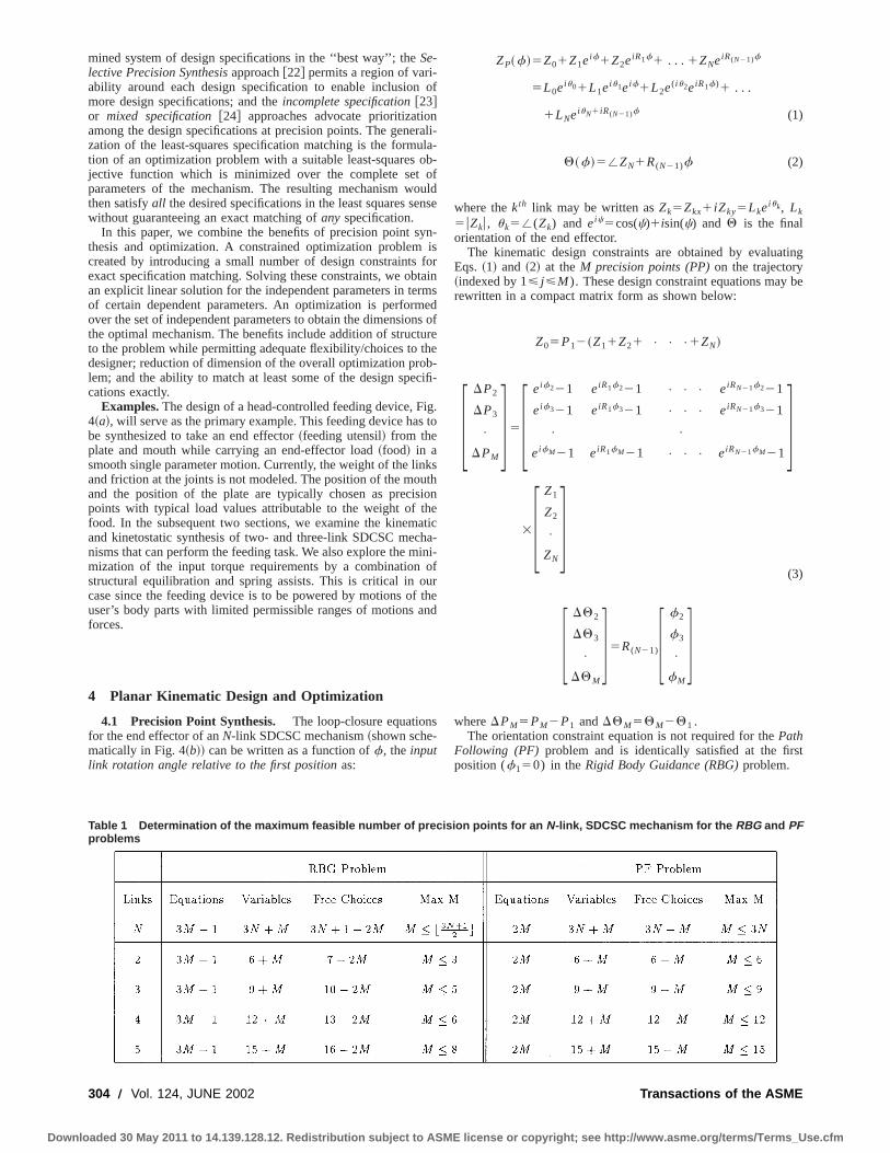
Fig. 4 „a… Schematic of operation of the head-controlled feeding device. „b… Physical and mathematical modelsof a 2-link SDCSC mechanism.
JUNE 2002, Vol. 124 Õ 303
cense or copyright; see http://www.asme.org/terms/Terms_Use.cfm
uo
o
y
r
nt
c
s
nu
h
f
s
ting
be
st
Downlo
mined system of design specifications in the ‘‘best way’’; theSe-lective Precision Synthesisapproach@22# permits a region of vari-ability around each design specification to enable inclusionmore design specifications; and theincomplete specification@23#or mixed specification@24# approaches advocate prioritizatioamong the design specifications at precision points. The genezation of the least-squares specification matching is the formtion of an optimization problem with a suitable least-squaresjective function which is minimized over the complete setparameters of the mechanism. The resulting mechanism wthen satisfyall the desired specifications in the least squares sewithout guaranteeing an exact matching ofany specification.
In this paper, we combine the benefits of precision point sthesis and optimization. A constrained optimization problemcreated by introducing a small number of design constraintsexact specification matching. Solving these constraints, we oban explicit linear solution for the independent parameters in teof certain dependent parameters. An optimization is performover the set of independent parameters to obtain the dimensiothe optimal mechanism. The benefits include addition of structo the problem while permitting adequate flexibility/choices to tdesigner; reduction of dimension of the overall optimization prolem; and the ability to match at least some of the design specations exactly.
Examples.The design of a head-controlled feeding device, F4~a!, will serve as the primary example. This feeding device habe synthesized to take an end effector~feeding utensil! from theplate and mouth while carrying an end-effector load~food! in asmooth single parameter motion. Currently, the weight of the liand friction at the joints is not modeled. The position of the moand the position of the plate are typically chosen as precispoints with typical load values attributable to the weight of tfood. In the subsequent two sections, we examine the kinemand kinetostatic synthesis of two- and three-link SDCSC mecnisms that can perform the feeding task. We also explore the mmization of the input torque requirements by a combinationstructural equilibration and spring assists. This is critical in ocase since the feeding device is to be powered by motions ouser’s body parts with limited permissible ranges of motions aforces.
4 Planar Kinematic Design and Optimization
4.1 Precision Point Synthesis. The loop-closure equationfor the end effector of anN-link SDCSC mechanism~shown sche-matically in Fig. 4~b!! can be written as a function off, the inputlink rotation angle relative to the first positionas:
304 Õ Vol. 124, JUNE 2002
aded 30 May 2011 to 14.139.128.12. Redistribution subject to ASME li
of
nrali-la-b-
ofuldnse
n-isfortainmseds of
ureheb-ifi-
ig.to
ksthioneaticha-ini-ofurthend
ZP~f!5Z01Z1eif1Z2eiR1f1 . . . 1ZNeiR(N21)f
5L0eiu01L1eiu1eif1L2e( iu2eiR1f)1 . . .
1LNeiuN1 iR(N21)f (1)
Q~f!5/ZN1R(N21)f (2)
where thekth link may be written asZk5Zkx1 iZky5Lkeiuk, Lk
5uZku, uk5/(Zk) and eic5cos(c)1isin(c) and Q is the finalorientation of the end effector.
The kinematic design constraints are obtained by evaluaEqs. ~1! and ~2! at theM precision points (PP)on the trajectory~indexed by 1< j <M ). These design constraint equations mayrewritten in a compact matrix form as shown below:
Z05P12~Z11Z21 • • •1ZN!
F DP2
DP3
•
DPM
G5F eif221 eiR1f221 • • • eiRN21f221
eif321 eiR1f321 • • • eiRN21f321
• •
eifM21 eiR1fM21 • • • eiRN21fM21G
3F Z1
Z2
•
ZN
G(3)
F DQ2
DQ3
•
DQM
G5R(N21)F f2
f3
•
fM
GwhereDPM5PM2P1 andDQM5QM2Q1 .
The orientation constraint equation is not required for thePathFollowing (PF) problem and is identically satisfied at the firposition (f150) in theRigid Body Guidance (RBG)problem.
Table 1 Determination of the maximum feasible number of precision points for an N-link, SDCSC mechanism for the RBG and PFproblems
Transactions of the ASME
cense or copyright; see http://www.asme.org/terms/Terms_Use.cfm
Journal of Mech
Downloaded 30 May 2011
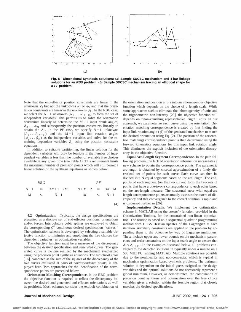
Fig. 5 Dimensional Synthesis solutions: „a… Sample SDCSC mechanism and 4-bar linkagesolutions for an RBG problem. „b… Sample SDCSC mechanism tracing an elliptical shape fora PF problem.
t
t
tt.
r
b
tiveileand
urOri-the
ch
thele.p-
s aetricis-be
end-
ased-arcf dis-and
a-ingachp-rs.ram-that
on-n aeinum
signnt aof
iceely
Note that the end-effector position constraints are linear inunknownsZj but not the unknownsRj or fk and that the orien-tation constraints are linear in the unknownsfk . In the RBG case,we select theN21 unknowns (R1 . . . R(N21)) to form the set ofindependent variables. This permits us to solve the orientaconstraints linearly to determine theM21 input crank angles,f2 . . . fM and subsequently the position constraints linearlyobtain the Zj . In the PF case, we specifyN21 unknowns(R1 . . . R(N21)) and the M21 input link rotation angles(f2 . . . fM) as the independent variables and solve for themaining dependent variablesZj using the position constrainequations.
In addition to suitable partitioning, the linear solution for thdependent variables will only be feasible if the number of indpendent variables is less than the number of available free choavailable at any given time~see Table 1!. This requirement limitsthe maximum number of precision points which will still permitlinear solution of the synthesis equations as shown below:
RBG PF
N21 < 3N1122M N1M22 < 3N2M
M < N11 M < N11
(4)
4.2 Optimization. Typically, the design specifications arpresented as a discrete set of end-effector positions, orientaand/or forces. Interpolatory cubic splines are employed to obthe correspondingC2 continuous desired specification ‘‘curvesThe optimization scheme is developed by selecting a suitablejective function to minimize and employing the free choices~in-dependent variables! as optimization variables.
The objective function must be a measure of the discrepabetween thedesiredspecification andgeneratedcurves. The gen-erated curve is the one realized by the mechanism synthesusing the precision point synthesis equations. Thestructural error@16#, computed as the sum of the squares of the discrepancy otwo curves evaluated at pairs ofcorrespondence points, is em-ployed here. Two approaches for the identification of the cospondence points are presented below.
Orientation Matching Correspondence.In the RBG problemthe objective function is required to reflect the discrepancytween the desired and generated end-effector orientations asas positions. Most schemes consider the explicit combination
anical Design
to 14.139.128.12. Redistribution subject to ASME li
the
ion
to
re-
ee-ices
a
eionsain’’ob-
ncy
ized
f the
re-
e-wellof
the orientation and position errors into an inhomogenous objecfunction which depends on the choice of a length scale. Whsome approaches seek to eliminate the inhomogeneity of unitsthe trigonometric non-linearity@25#, the objective function stilldepends on ‘‘non-vanishing representative length’’ units. In oapproach, we parameterize each curve using the orientation.entation matching correspondence is created by first findinginput link rotation angle (f) of the generated mechanism to matthe desired orientation using Eq.~2!. The position of the~orienta-tion matching! correspondence point is then determined usingforward kinematics equations for this input link rotation angThis eliminates the explicit inclusion of the orientation discreancy in the objective function.
Equal Arc-Length Segment Correspondence.In the path fol-lowing problem, the lack of orientation information necessitatenew scheme to obtain the correspondence points. The paramarc-length is obtained by chordal approximation of a finely dcretized set of points for each curve. Each curve can thendivided into N equal segments based on the arc-length. Thepoints of each segment~on the two curves! form the two sets ofpoints that have a one-to-one correspondence to each other bon the arc-length measure. The structural error with equallength correspondence points accurately assesses the extent ocrepancy and that convergence to the correct solution is rapidis discussed further in@26#.
Implementation Details. We implement the optimizationscheme in MATLAB using theconstr( ) function, provided in theOptimization Toolbox, for the constrained non-linear optimiztion. The routine is based on a sequential quadratic programmmethod with BFGS Hessian updates of the Lagrangian at eiteration. Auxiliary constraints are applied to the problem by apending them to the objective by way of Lagrange multiplieThese include upper and lower bounds on the mechanism paeters and order constraints on the input crank angle to ensuref j,f ( j 11) . In the examples discussed below, all problems cverged to the depicted solutions in typically under a minute o500 MHz PC running MATLAB. Multiple solutions are possibldue to the nonlinearity and non-convexity, which is typicalmechanism optimization-based synthesis problems. The optimsolution is dependent on the initial guess assigned to the devariables and the optimal solutions do not necessarily represeglobal minimum. However, as demonstrated, the combinationprecision point synthesis and optimization over the free chovariables gives a solution within the feasible region that closmatches the desired specifications.
JUNE 2002, Vol. 124 Õ 305
cense or copyright; see http://www.asme.org/terms/Terms_Use.cfm
m
don.PF
sent
gd-nktingns.
Ad tok,
eeptoel-he.e-
er
ksthe
endsC
Downlo
4.3 Planar Kinematic Design Examples. An optimal2-link SDCSC mechanism solution to the Rigid Body Guidanproblem is illustrated in Fig. 5~a! for a typical feeding task dis-cussed in the previous section. The solid line PQR depicts2-link SDCSC mechanism at the first precision point and the tlines depict the mechanism through the various stages of thetion. For comparison, an optimal four-bar solution for the sadataset is superposed in the figure to demonstrate the relativeof the two configurations. ABCD denote the four joints of th
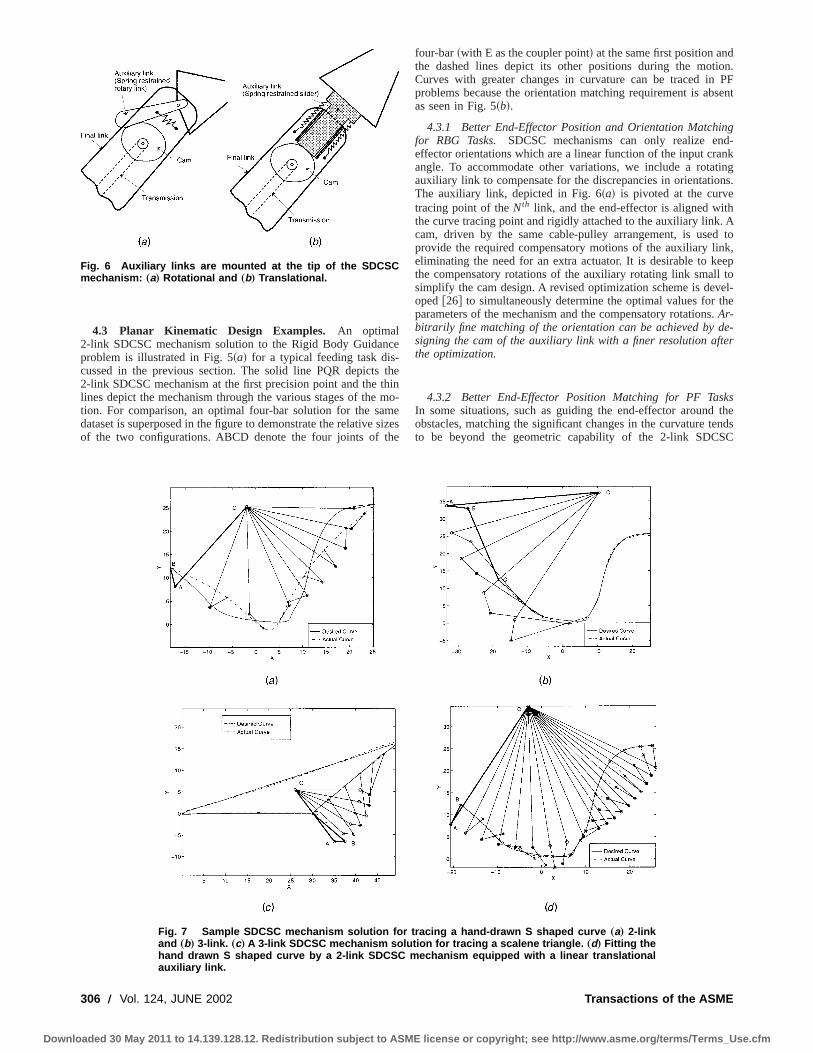
Fig. 6 Auxiliary links are mounted at the tip of the SDCSCmechanism: „a… Rotational and „b… Translational.
306 Õ Vol. 124, JUNE 2002
aded 30 May 2011 to 14.139.128.12. Redistribution subject to ASME li
ce
thehinmo-
esizese
four-bar~with E as the coupler point! at the same first position anthe dashed lines depict its other positions during the motiCurves with greater changes in curvature can be traced inproblems because the orientation matching requirement is abas seen in Fig. 5~b!.
4.3.1 Better End-Effector Position and Orientation Matchinfor RBG Tasks. SDCSC mechanisms can only realize eneffector orientations which are a linear function of the input craangle. To accommodate other variations, we include a rotaauxiliary link to compensate for the discrepancies in orientatioThe auxiliary link, depicted in Fig. 6~a! is pivoted at the curvetracing point of theNth link, and the end-effector is aligned withthe curve tracing point and rigidly attached to the auxiliary link.cam, driven by the same cable-pulley arrangement, is useprovide the required compensatory motions of the auxiliary lineliminating the need for an extra actuator. It is desirable to kthe compensatory rotations of the auxiliary rotating link smallsimplify the cam design. A revised optimization scheme is devoped@26# to simultaneously determine the optimal values for tparameters of the mechanism and the compensatory rotationsAr-bitrarily fine matching of the orientation can be achieved by dsigning the cam of the auxiliary link with a finer resolution aftthe optimization.
4.3.2 Better End-Effector Position Matching for PF TasIn some situations, such as guiding the end-effector aroundobstacles, matching the significant changes in the curvature tto be beyond the geometric capability of the 2-link SDCS
Fig. 7 Sample SDCSC mechanism solution for tracing a hand-drawn S shaped curve „a… 2-linkand „b… 3-link. „c… A 3-link SDCSC mechanism solution for tracing a scalene triangle. „d… Fitting thehand drawn S shaped curve by a 2-link SDCSC mechanism equipped with a linear translationalauxiliary link.
Transactions of the ASME
cense or copyright; see http://www.asme.org/terms/Terms_Use.cfm
v
i
a
t
f
o
i
a
nr
po
lar
ionby
al
heereasitsue,
theat
ha-
Downlo
mechanism, as shown in Fig. 7~a!. Two options are explored toenhance the capabilities of the SDCSC mechanisms in suchations.
Increasing the number of links while retaining the singdegree-of-freedom SDCSC configuration enhances the geomcurve tracing capability of the SDCSC mechanism. The improtracing of the same hand-drawn curve with a three-link mecnism, while retaining a linear PPS procedure for 4 precispoints, is shown in Fig. 7~b!. The increased number of links alsoffers greater flexibility in tracing other complex curves suchthe scalene triangle shown in Fig. 7~c!.
As an alternative, we can consider adding a cam-driven axiextensible final link, shown in Fig. 7~b!, driven by the input crankmotion. A revised optimization problem is used to determinedimensions of the optimal SDCSC mechanism, Fig. 7~d!, to per-form the task while keeping the required auxiliary translatiosmall @26#. The auxiliary translation link can now provideexactcurve matchingsince the cam can be designed appropriately athe mechanism synthesis.
5 Planar Kinetostatic Design and OptimizationSingle degree-of-freedom mechanisms/linkagescan generate
end-effector forcesonly in directions tangential to the end-effectmotion and structurally equilibrate forces in all other directionHence, we will explore the design of a mechanism to guide a rbody while supportingarbitrarily specified external loads—by acombination of the structural equilibration and actuation— at eposition along the trajectory.
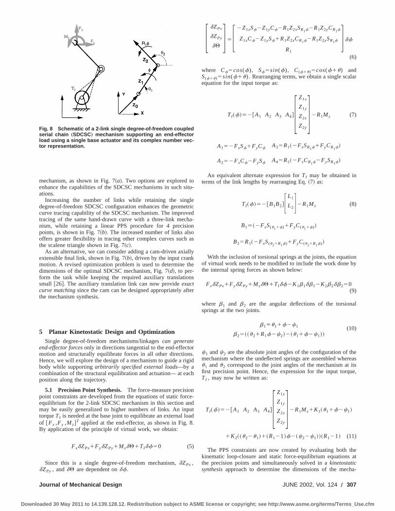
5.1 Precision Point Synthesis. The force-measure precisiopoint constraints are developed from the equations of static foequilibrium for the 2-link SDCSC mechanism in this section amay be easily generalized to higher numbers of links. An intorqueTI is needed at the base joint to equilibrate an external lof @Fx ,Fy ,Mz#
T applied at the end-effector, as shown in Fig.By application of the principle of virtual work, we obtain:
FxdZPx1FydZPy1MzdQ1TIdf50 (5)
Since this is a single degree-of-freedom mechanism,dZPx ,dZPy , anddQ are dependent ondf.
Fig. 8 Schematic of a 2-link single degree-of-freedom coupledserial chain „SDCSC… mechanism supporting an end-effectorload using a single base actuator and its complex number vec-tor representation.
Journal of Mechanical Design
aded 30 May 2011 to 14.139.128.12. Redistribution subject to ASME li
situ-
leetriced
ha-onoas
lly
he
ns
ter
rs.
gid
ch
ce-ndutad
8.
F dZPx
dZPy
dQG5F 2Z1xSf2Z1yCf2R1Z2xSR1f2R1Z2yCR1f
Z1xCf2Z1ySf1R1Z2xCR1f2R1Z2ySR1f
R1
G df
(6)
where Cf5cos(f), Sf5sin(f), C(f1u)5cos(f1u) andS(f1u)5sin(f1u). Rearranging terms, we obtain a single scaequation for the input torque as:
TI~f!52@A1 A2 A3 A4#F Z1x
Z1y
Z2x
Z2y
G2R1Mz (7)
A152FxSf1FyCf A35R1~2FxSR1f1FyCR1f!
A252FxCf2FySf A45R1~2FxCR1f2FySR1f!
An equivalent alternate expression forTI may be obtained interms of the link lengths by rearranging Eq.~7! as:
TI~f!52@B1B2#F L1
L2G2R1Mz (8)
B15~2FxS(u11f)1FyC(u11f)!
B25R1~2FxS(u21R1f)1FyC(u21R1f)!
With the inclusion of torsional springs at the joints, the equatof virtual work needs to be modified to include the work donethe internal spring forces as shown below:
FxdZPx1FydZPy1MzdQ1TIdf2K1b1db12K2b2db250(9)
where b1 and b2 are the angular deflections of the torsionsprings at the two joints.
b15u11f2c1
b25~~u21R1f2c2!2~u11f2c1!!(10)
c1 andc2 are the absolute joint angles of the configuration of tmechanism where the undeflected springs are assembled whu1 andu2 correspond to the joint angles of the mechanism atfirst precision point. Hence, the expression for the input torqTI , may now be written as:
TI~f!52@A1 A2 A3 A4#F Z1x
Z1y
Z2x
Z2y
G2R1Mz1K1~u11f2c1!
1K2~~u22u1!1~R121!f2~c22c1!!~R121! (11)
The PPS constraints are now created by evaluating bothkinematic loop-closure and static force-equilibrium equationsthe precision points and simultaneously solved in akinetostaticsynthesisapproach to determine the dimensions of the mec
JUNE 2002, Vol. 124 Õ 307
cense or copyright; see http://www.asme.org/terms/Terms_Use.cfm

Downl
Table 2 Enumeration of free choices for a two-link SDCSC mechanism for the PF problem with kinetostatic specifications—without and with spring assists for V iÄu i and V iÅu i for various precision points
d
aeto
o
n
pi
i
on-ints
of
n of
ases
ofionthe
sionn
i-ase
o
nism. Huang and Roth@20# note that combining the position anstatic-equilibrium constraints drastically limits the numberreachable precision points for the four-bar mechanism. This istrue for the 2-link SDCSC mechanism—see Table 2. Springments add extra design variables without adding design equapermitting the design for a slightly larger number of precisipositions. Methods such as incomplete design specification@23# ormixed design specification@24# are also important here since thereduce the number of the design equations per precision ppermitting more precision points. For example, astatic synthesisapproach may be employed in situations where the positioirrelevant using only constraints on theforce measureat precisionpoints.
5.2 Planar Kinetostatic Design Examples
5.2.1 Example A: Peak Torque Minimization.In this ex-ample, a 2-link SDCSC mechanism is designed to matchscribed position and force specifications at two precision poexactly while minimizing the absolute value of the peak torquover the rest of the trajectory. In the feeder design case, theprecision points are selected to be at the beginning and end omotion, the positions of the plate~218.29 cm, 4.41 cm! and themouth~25.19 cm, 25.19 cm!. Further, we desire these to be postions of rest to be maintained without exerting any torque (TI 1
5TI 250). Finally, we will require the transition between pos
tions to be accomplished using the smallest input-torques, wsupporting a constant end-effector load (F5@0,21#TN). We ex-amine the feasibility of achieving this goal without the usesprings ~Case I! and later demonstrate the benefits of addsprings to lower the required input torques~Cases II and III!.
Case I: Without Springs. The optimization problem may bestated as:
minR1 ,f2
maxf
uT~f!u
subject to:
F XP22XP1
YP22YP1
TI 11R1MZ1
TI 21R1MZ2
G5F M11 M12 M13 M14
M21
M22 M23 M24
A11 A12 A13 A14
A21 A22 A23 A24
GF Zx1
Zy1
Zx2
Zy2
G
308 Õ Vol. 124, JUNE 2002aded 30 May 2011 to 14.139.128.12. Redistribution subject to ASME li
oflsole-ionsn
yint,
is
re-ntsestwof the
i-
i-hile
ofng
where
M115~Cf221! M215Sf2
M1252Sf2M225~Cf2
21!
M135~CR1f221! M235SR1f2
M1452SR1f2M245~CR1f2
21!
Ak15~FxkSfk
2FykCfk
! Ak35R1~FxkS(R1fk)2Fyk
CR1fk!
Ak25~FxkCfk
1FykSfk
! Ak45R1~FxkCR1fk
1FykSR1fk
!
(12)
The first two scalar equations represent the kinematic cstraints while the remaining two are the force-measure constraat the two precision points. The selection ofR1 and f2 as freechoices yields a strongly coupled system~in the kinematic andforce-measure equations! but makes the solution of the systemequations linearly for the remaining unknownsZx1 , Zy1 , Zx2 , Zy2possible.
Spring assists alter the desired input torques via the equatiovirtual work, adding new variables –V i , the absolute joint con-figuration when springs are attached; andk i the springconstants—but do not add other new equations. Two further cresult when the springs are added and are discussed next.
Case II: Springs Assembled at the Initial Configuration„ViÄui…. The first case is one where the undeflected positionthe springs occurs when the end effector is at the first precispoint. Such an assumption is useful in a practical setting sincemounting of the springs can be guaranteed at the first precipoint. ThusV i5u i which considerably simplifies the expressiofor the contribution to the input torques:
TSpring~f!52k1f2k2~R121!2f(13)
TInput5TEquil2TSpring
The new variablesk1 andk2 increase the total number of varables by two. We continue to treat the two-precision point cemploying an increased number of free choices,f2 , R1 , k1 and
Transactions of the ASME
cense or copyright; see http://www.asme.org/terms/Terms_Use.cfm
Journa
Downloaded 30
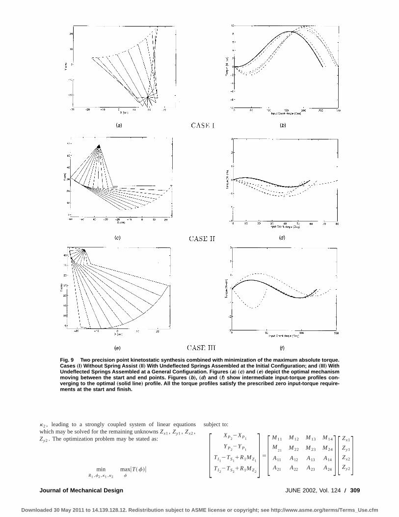
Fig. 9 Two precision point kinetostatic synthesis combined with minimization of the maximum absolute torque.Cases „I… Without Spring Assist „II… With Undeflected Springs Assembled at the Initial Configuration; and „III… WithUndeflected Springs Assembled at a General Configuration. Figures „a… „c… and „e… depict the optimal mechanismmoving between the start and end points. Figures „b…, „d… and „f… show intermediate input-torque profiles con-verging to the optimal „solid line … profile. All the torque profiles satisfy the prescribed zero input-torque require-ments at the start and finish.
k2 , leading to a strongly coupled system of linear equatiowhich may be solved for the remaining unknownsZx1 , Zy1 , Zx2 ,Zy2 . The optimization problem may be stated as:
minR1 ,f2 ,k1 ,k2
maxf
uT~f!u
l of Mechanical Design
May 2011 to 14.139.128.12. Redistribution subject to ASME li
nssubject to:
F XP22XP1
YP22YP1
TI 12TS1
1R1MZ1
TI 22TS2
1R1MZ2
G5F M11 M12 M13 M14
M21
M22 M23 M24
A11 A12 A13 A14
A21 A22 A23 A24
GF Zx1
Zy1
Zx2
Zy2
G
JUNE 2002, Vol. 124 Õ 309cense or copyright; see http://www.asme.org/terms/Terms_Use.cfm

bw
I
la
r
t
ids-tionilitytheionralin
of9. In
start. In
ves.isherofig-
fileof
rofile
ismbarle
eby:
jec-si-hisopti-ng inn of
apedctor
a-ainandure
Downlo
where
M115~Cf221! M215Sf2
M1252Sf2M225~Cf2
21!
M135~CR1f221! M235SR1f2
M1452SR1f2M245~CR1f2
21!
Ak15~FxkSfk
2FykCfk
! Ak35R1~FxkSR1fk
2FykCR1fk
!
Ak25~FxkCfk
1FykSfk
! Ak45R1~FxkCR1fk
1FykSR1fk
!
TS150 TS2
52k1f22k2~R121!2f2
(14)
Case III: Springs Assembled at a General Configuration„ViÅui…. In many cases, we would like all precision points to‘‘load-bearing.’’ Hence, we assemble the springs at positions afrom the precision points so as to preload the mechanism atconfigurations reached at the precision points (V iÞu i). Note thatthe constraints written using Cartesian link coordinates are nouseful here. In their stead, we express all the constraints~kine-matic and static! in terms of the magnitudes of the link lengths.recasting the equations, the system of equations is linear in teof the magnitudes of various link lengths which are now selecto be the dependent parameters. The spring constants are seas the other dependent parameters. The combined system mwritten in matrix form as seen in the constraints of Eq.~15!. The6 available free choices are used to specifyf2 , R1 ,u1 , u2 ,V1 ,V2 which leads to a weakly coupled system of linear equations@4#which may be solved for the dependent variablesL1 , L2 , k1 , k2 .
The weak coupling implies that the kinematic equations mfirst be solved independently for a few of the variablesL1 , L2 .These results are then used to solve the static equations foremaining unknownsk1 , k2 . We will, however, prefer to solvethe combined system of equations and perform the optimizaon the entire set of variables simultaneously. Note that care malso be taken to ensure non-negative values for the depenvariables in this case.
minR1 ,f2 ,u1 ,u2 ,V1 ,V2
maxf
uT~f!u (15)
subject to:
F XP22XP1
YP22YP1
TI 11R1Mz1
TI 21R1Mz2
G5F M11 M12 0 0
M21 M22 0 0
A11 A12 A13 A14
A21 A22 A23 A24
GF L1
L2
k1
k2
Gwhere
310 Õ Vol. 124, JUNE 2002
aded 30 May 2011 to 14.139.128.12. Redistribution subject to ASME li
eaythe
t as
nrmstedectedy be
ay
the
ionust
dent
M115C(u11f2)2Cu1A115~Fx1
Su12Fy1
Cu1!
M125C(u21R1f2)2Cu2A125R1~Fx1
Su22Fy1
Cu2!
M215S(u11f2)2Su1A215Fx2
S(u11f2)2Fy2C(u11f2)
M225S(u21R1f2)2Su2A225R1Fx2
S(u21R1f2)
2R1Fy2C(u21R1f2)
D115~u12V1! D215~u11f22V1!
D125~u22V2! D225~u21R1f22V2!
2~u12V1! 2~u11f22V1! (15)
Discussion.In our experience with several examples, we dnot experience any difficulty with the min-max formulation, posibly because the precision point equations lead the optimizato the portion of the design space where the non-differentiabis not a problem. However, we note that it is possible to recastabove min-max problem easily as a constrained minimizatproblem by introducing an additional slack variable and seveadditional inequality constraints, a technique commonly usedstructural optimization.
The results of the optimization over the free choices in eachthe three cases are depicted each of the three rows of Fig.each of the figures on the left hand side,~a!, ~c!, and ~e!, theobtained mechanism solution is depicted moving between theand end points, which were selected to be the precision pointsthe figures on the right,~b!, ~d!, and~f!, the several intermediateinput torque profiles~dashed lines! are shown converging to theoptimal ~solid line! profile. The final profile~solid curve! has thelowest absolute value of the peak torque among all other curNote that all the position profiles interpolate the start and finpoints and that the torque profiles satisfy the prescribed zinput-torque requirements at these positions. Comparing theures on the right,~b!, ~d!, and~f!, we would like to emphasize thereductionin the required torques in Cases II and III byan order ofmagnitudedue to the addition of spring assists.
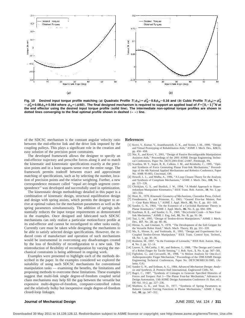
5.2.2 Example B: Position-Independent Input Torque ProMatching. Four-bar linkages have been used in the designexercise machines to give their users a shaped exercise pusing a constant load/weight@3#. In this example, we will demon-strate the distinct benefits of using a 2-link SDCSC mechansupporting a constant end-effector weight, instead of a four-linkage. The user interacts primarily only with the input handattached to the rotation of the base joint and so the motion~posi-tion profile! of the end-effector is not relevant. Hence a widvariety of desired shaped input torque profiles can be realized~a! eliminating the dependence on the positions from the obtive; and~b! supplanting the constraints on the end-effector potion with further design specifications on the input torques. Tincrease in the number of torque specifications enhances themization process by reducing the feasible search space resultia more rapid convergence. Representative results of the desigmechanisms which use the shaped quadratic and cubic shinput torque profile to support the constant load at the end-effeare presented here in Fig. 10 and discussed further in@26#.
6 ConclusionIn this paper, we introduced a novel configuration of mech
nisms called Single Degree-of-freedom Coupled Serial Ch~SDCSC! mechanisms and presented a general frameworkmethodology for their synthesis for planar tasks. A salient feat
Transactions of the ASME
cense or copyright; see http://www.asme.org/terms/Terms_Use.cfm
Downlo
Fig. 10 Desired input torque profile matching „a… Quadratic Profile T„fN…ÄfN2À0.6fNÀ0.16 and „b… Cubic Profile T„fN…ÄfN
3
ÀfN2¿0.08fN¿0.064 where fNÄ„fÕ60…. The final designed mechanism is required to support an applied load of FĆ0,À1‡TN at
the end effector using the desired input torque profile „solid line …. The intermediate non-optimal torque profiles are shown indotted lines converging to the final optimal profile shown in dashed „– –… line.
at
e
o
otii
rC
eia
n
gn
onni-
pti-ed-
aper
s
r-
.Part
in
r-
h.
for
r al.,
g.,
trol
.ign
-
ofs in
tong.
of the SDCSC mechanism is the constant angular velocity rbetween the end-effector link and the drive link imposed bycoupling pulleys. This plays a significant role in the creation aeasy solution of the precision point constraints.
The developed framework allows the designer to specifyend-effector trajectory and prescribe forces along it and to mathe kinematic and kinetostatic specifications exactly at the prsion points and in a least squares sense over the entire rangeframework permits tradeoff between exact and approximmatching of specifications, such as by selecting the number, ltion of precision points and the relative weighting. Further, a ncorrespondence measure called ‘‘equal arc-length segment cspondence’’ was developed and successfully used in optimiza
The kinetostatic design methodology detailed in this papercombination of kinematic design, structural equilibration desand design with spring assists, which permits the designer torive at optimal values for the mechanism parameters as well asspring parameters simultaneously. The addition of springs sstantially reduces the input torque requirements as demonstin the examples. Once designed and fabricated such SDmechanisms can only realize a particular motion/force profileits end-effector and cannot be reconfigured to other tasks eaCurrently care must be taken while designing the mechanismbe able to satisfy selected design specifications. However, thduced costs of manufacture and operation of such mechanwould be instrumental in overcoming any disadvantages creby the loss of flexibility of reconfiguration to a new task. Threintroduction of flexibility of reconfiguration by varying the mechanical constraints is being addressed in ongoing work.
Examples were presented to highlight each of the methodsscribed in the paper. In the examples considered we exploredsuitability of using such SDCSC mechanisms for conventiomanipulation tasks — examining the benefits, the limitations aproposing methods to overcome these limitations. These examsuggest that multi-link single degree-of-freedom coupled sechain mechanisms may help fill the gap between the versatileexpensive multi-degree-of-freedom, computer-controlled roband the relatively bulky but inexpensive single degree-of-freedclosed-loop linkages.
Journal of Mechanical Design
aded 30 May 2011 to 14.139.128.12. Redistribution subject to ASME li
tiohend
antchci-
. Theateca-
ewrre-
ion.s agnar-the
ub-atedSCat
sily.s to
re-smstede-
de-thealndplesrialbutotsom
References@1# Krovi, V., Kumar, V., Ananthasuresh, G. K., and Vezien, J.-M., 1999, ‘‘Desi
and Virtual Prototyping of Rehabilitation Aids,’’ ASME J. Mech. Des.,121~3!,pp. 456–458.
@2# Nie, X., and Krovi, V., 2001, ‘‘Design of Passive Reconfigurable ManipulatiAssistive Aids,’’ Proceedings of the 2001 ASME Design Engineering Techcal Conferences, Paper No. DETC2001/DAC-21087, Pittsburgh, PA.
@3# Scardina, M. T., Soper, R. R., Calkins, J. M., and Reinholtz, C., 1995, ‘‘Omal Synthesis of Force Generating Planar Four-link Mechanisms,’’ Proceings of the 4th National Applied Mechanisms and Robotics Conference, PNo. AMR 95-003, Cincinnati, OH.
@4# Howell, L. L., and Midha, A., 1996, ‘‘A Loop Closure Theory for the Analysiand Synthesis of Compliant Mechanisms,’’ ASME J. Mech. Des.,118, No. 1,pp. 121–126.
@5# Chirikjian, G. S., and Burdick, J. W., 1994, ‘‘A Model Approach to Hyperedundant Manipulator Kinematics,’’ IEEE Trans. Rob. Autom.,10, No. 3, pp.343–354.
@6# Hunt, K., 1978,Kinematic Geometry of Mechanisms, Clarendon Press, Oxford@7# Freudenstein, F., and Primrose, E., 1963, ‘‘Geared Five-bar Motion,
1—Gear Ratio Minus 1,’’ ASME J. Appl. Mech.,85, No. E, pp. 161–169.@8# Sandor, G. N., 1964, ‘‘On the Existence of a Cycloidal Burmester Theory
Planar Kinematics,’’ ASME J. Appl. Mech.,86, No. E, pp. 694–699.@9# Kaufman, R. E., and Sandor, G. N., 1969, ‘‘Bicycloidal Crank—A New Fou
link Mechanism,’’ ASME J. Eng. Ind.,91, No. B, pp. 91–96.@10# Tsai, L.-W., 1995, ‘‘Design of Tendon-driven Manipulators,’’ ASME J. Mec
Des.,117, No. 2B, pp. 80–86.@11# Hirose, S., and Umetani, Y., 1978, ‘‘The Development of the Soft Gripper
the Versatile Robot Hand,’’ Mech. Mach. Theory,13, pp. 351–359.@12# Ma, S., Hirose, S., and Yoshinada, H., 1993, ‘‘Design and Experiments fo
Coupled Tendon-Driven Manipulator,’’ IEEE Trans. Control Syst. Techno13, No. 1, pp. 30–36.
@13# Rosheim, M., 1997, ‘‘In the Footsteps of Leonardo,’’ IEEE Rob. Autom. Ma4, No. 2, pp. 12–14.
@14# Leaver, S., McCarthy, J. M., and Bobrow, J., 1988, ‘‘The Design and Conof a Robot Finger for Tactile Sensing,’’ J. Rob. Syst.,5, No. 6, pp. 567–581.
@15# Figliolini, G., and Ceccarelli, M., 1998, ‘‘A Motion Analysis for One-d.o.fAnthropomorphic Finger Mechanism,’’ Proceedings of the 1998 ASME DesEngineering Technical Conferences, Paper No. DETC98/MECH-5985,~At-lanta, GA!.
@16# Sandor G. N., and Erdman, A. G., 1984,Advanced Mechanism Design: Analysis and Synthesis, 2, Prentice Hall International, Englewood Cliffs, NJ.
@17# Bagci, C., 1987, ‘‘Synthesis of Linkages to Generate Specified HistoriesForces and Torques: Part 1—The Planar Four-bar Mechanism,’’ AdvanceDesign Automation, 13th ASME Design Automation Conference~S. Rao, ed.!,DE-Vol. 10-2, pp. 227–236.
@18# Matthew, G. K., and Tesar, D., 1977, ‘‘Synthesis of Spring ParametersBalance General Forcing Functions in Planar Mechanisms,’’ ASME J. EInd., 99, pp. 347–352.
JUNE 2002, Vol. 124 Õ 311
cense or copyright; see http://www.asme.org/terms/Terms_Use.cfm

a
n
t
yt
e-
ndm.
aresh.
veni-
Downlo
@19# Idlani, S., Streit, D. A., and Gilmore, B. J., 1993, ‘‘Elastic PotentiSynthesis—A Generalized Procedure for Dynamic Synthesis of MachineMechanism Systems,’’ ASME J. Mech. Des.,115, No. 3, pp. 568–575.
@20# Huang, C., and Roth, B., 1993, ‘‘Dimensional Synthesis of Closed-loop Liages to Match Force and Position Specifications,’’ ASME J. Mech. Des.,115,No. 2, pp. 194–198.
@21# Sarkisyan, Y. L., Gupta, K. C., and Roth, B., 1973, ‘‘Kinematic GeomeAssociated with the Least Square Approximation of a Given Motion,’’ ASMJ. Eng. Ind.,95, pp. 503–510.
@22# Kramer, S. N.,Selective Precision Synthesis of Planar Mechanisms SatisfPractical Design Requirements, Ph.D. thesis, Rennsalear Polytechnic InstituTroy, NY.
312 Õ Vol. 124, JUNE 2002
aded 30 May 2011 to 14.139.128.12. Redistribution subject to ASME li
land
k-
ryE
inge,
@23# Tsai, L.-W., and Roth, B., 1973, ‘‘Incompletely Specified Displacements: Gometry and Spatial Linkage Synthesis,’’ ASME J. Eng. Ind.,95, pp. 603–611.
@24# Chuang, J. C., and Waldron, K. J., 1983, ‘‘Synthesis with Mixed Motion aPath Generation Position Specifications,’’ ASME J. Mech., Transm., AutoDes.,105, No. 4, pp. 617–624.
@25# Akhras, R., and Angeles, J., 1990, ‘‘Unconstrained Nonlinear Least-squOptimization of Planar Linkages for Rigid-body Guidance,’’ Mech. MacTheory,25, pp. 97–118.
@26# Krovi, V., 1998,Design and Virtual Prototyping of User-Customized AssistiDevices, Ph.D. thesis, Mechanical Engineering and Applied Mechanics, Uversity of Pennsylvania.
Transactions of the ASME
cense or copyright; see http://www.asme.org/terms/Terms_Use.cfm