kinematic and unsteady aerodynamic study on bi- … (2016), vol. 4, no. 1, pp.1{23 37 kinematic and...
TRANSCRIPT

ASDJournal (2016), Vol. 4, No. 1, pp. 1–23∣∣∣ 37
Kinematic and Unsteady Aerodynamic Study onBi- and Quad-Wing Ornithopter
H.Djojodihardjo1
A.S.S.Ramli1
M.A.A.Bari2
(Received: March 17, 2014. Revised: April 28, 2015. Accepted: June 23, 2016)
AbstractThe potential of Flapping Wing Micro Air Vehicles (MAVs) for sensing and informationgathering relevant for environmental and disaster monitoring and security surveillanceleads to the identification and modeling the salient features and functional significanceof the various components in the flying reasonably sized biosystems. The dynamics,kinematics and aerodynamics of their wing systems and the production of mechanicalpower output for lift and thrust will be synthesized following a simplified and generic,but meticulous, model for a flapping wing ornithopter. Basic unsteady aerodynamicapproach incorporating viscous effect and leading-edge suction is utilized. The firstpart of the study is focused on a bi-wing ornithopter. Later, parametric study is carriedout to obtain the lift and thrust physical characteristics in a complete cycle for evalu-ating the plausibility of the aerodynamic model and for the synthesis of an ornithoptermodel with simplified mechanism. Further analysis is carried out by differentiating thepitching and flapping motion phase-lag and studying its respective contribution to theflight forces. A similar procedure is then applied to flapping quad-wing ornithoptermodel. Results are discussed in comparison with various selected simple models in theliterature, with a view to develop a practical ornithopter model.
1 Introduction
Motivated by flying biosystems, flight engineering has been initiated since hun-dreds of years ago and has gradually grown from the time of Leonardo Da Vincito Otto Lilienthal’s gliders, to modern aircraft technologies and present flappingflight research. Recent interest in the latter has grown significantly particularlyfor small flight vehicles (or Micro-Air-Vehicles) with very small payload carryingcapabilities to allow remote sensing missions in hazardous as well as confinedareas. Some of these vehicles may have a typical wingspan of 15 cm, with aweight restriction of less than 100 g [1]. Perhaps the most comprehensive ac-count of insect flight or entomopter to date is given by Weis-Fogh [2], Ellington[3-5], Shyy et al [6,7], Dickinson et al [8], bikowski [9] and Ansari et al [10],while one of the first successful attempts to develop birdlike flapping flight wasmade by DeLaurier [11]. In a recent paper, Wang [12, 13] has elaborated thepeculiar nature of insects hovering, which has been efficiently acquired not bythe dominant aerodynamic lift, but by the drag in a paddling like motion.
Although our interest in developing a mathematical and experimental modelis on more or less rigid bi- and quad- wing ornithopter, it should also take noteon other relevant lightweight, flexible wings characteristics of insects and hum-mingbirds, that undergo large deformations while flapping, which can increasethe lift of flapping wings (Rosenfeld [14]), as applicable.
In the past, flapping wing designs have been created with varied success, forforward or hover mode, but not both, based on observations of hummingbirdsand bats (Nicholson et al [15]). According to Maybury and Lehmann [16], thedragonfly has the capability to shift flight modes simply by varying the phase lagbetween its fore and hind wings. With that observation, a quad-winged flapping
1 Department of Aerospace Engineering, Faculty of Engineering, Universiti Putra Malaysia,43400 UPM Serdang, Selangor, Malaysia2 Aerodynamics & Flight Mechanics Research Group, University of Southampton, Southamp-ton SO17 1BJ, UK.
doi:10.3293/asdj.2016.31

∣∣∣ 38 Kinematic and Unsteady Aerodynamic Study ...
Figure 1: a. Pterosaur[19]; b. Soaring eagle c.A dragonfly exhibiting itswing geometry and struc-tural detail.
Figure 2: (a) and (b)Upstroke and downstrokemotion of dragonfly(Adapted from [20]); (c)Saving power by elimi-nating a half stroke innormal hovering [12, 13].
system could be conceived as the simplest mechanism that has the capabilitiesto shift between flight modes [17]. In one of the recent works in developing quadflapping wing micro air vehicle, Ratti [17] has theoretically shown that a flightvehicle with four flapping wings has 50% higher efficiency than that with twoflapping wings. Inspired by the flight of a dragonfly, Prosser [18] analyzed, devel-oped and demonstrated a Quad-Wing Micro Air Vehicle (QW-MAV) which canproduce higher aerodynamic performance and energy efficiency, and increasedpayload capacity compared to a conventional flapping wing MAV (FW-MAV).In developing a generic model of flapping wing ornithopter, the bi-wing or-nithopter will first be reviewed and developed, and then extended to quad-wingornithopter. In addition, the present approach is aimed at finding the simplestornithopter configuration which can be used as the baseline for progressive andcontinued development. Also, by analyzing and synthesizing simple ornithopterconfiguration, the latter can be built into a simple mechanized one that can beused for experimental studies and further development. For this purpose, thesequence of Figs. 1 to 3 is presented, which are ordered according to the wingstructure characteristics. Fig. 1 exhibits wing geometries of a Pterosaur, aneagle and a dragonfly, which could inspire the development of the geometricaland aerodynamic modelling of an ornithopter.
The image displayed in Fig. 2 exhibit a dragonfly, which will later be im-itated to take advantage of the quad-wing kinematic and aerodynamic inter-actions, in the effort of improving the performance of the ornithopter to bedeveloped. Fig. 2 also schematically exhibits the flapping motion of the quad-wing dragonfly, as studied by Wang and Russell [20]. It is of interest to notethat a systematic study by Wang [12, 13] shows that in the case of insects withdominant hovering movement, due to comparable lift and drag components ofthe aerodynamic force, the sustainment of flight is attributed to the drag, likein paddling movement. Fig. 2 (c), adapted from Wang [12, 13], shows how byeliminating a half stroke in hovering, like in dragonfly, power efficiency can beachieved.
Taha et al [21] made a thorough review of the significant work done so farin the area of flight dynamics and control of flapping-wing micro-air vehicles(MAVs), covering the flapping kinematics, the aerodynamic modeling, and thebody dynamics. They identified the missing gap between hover and forwardspeed movement, where k>0.1, flapping frequency ω in the order of the bodynatural frequency, and relative flow angle α>25o or dynamic stall, where thereis dominant LEV contribution and coupling between the aerodynamic forcesand the body modes.
Addressing this gap and in dealing with LEV, Taha et al [22] embarkedupon a novel approach of using a state-space formulation for the aerodynamicsof flapping flight by extending the Duhamel’s principle in the linear unsteadyflows to non-conventional lift curves to capture the LEV contribution. Theirproposed model has been validated through a comparison with direct numericalsimulations of Navier–Stokes on hovering insects.
Vol. 4, No. 1, pp. 1–23 ASDJournal
H.Djojodihardjo, A.S.S.Ramli, M.A.A.Bari∣∣∣ 39
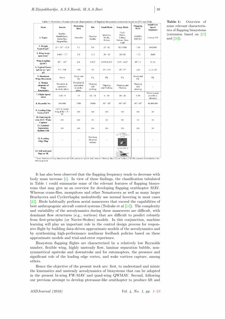
Table 1: Overview ofsome relevant characteris-tics of flapping biosystems(extension based on [25]and [26]).
It has also been observed that the flapping frequency tends to decrease withbody mass increase [6]. In view of these findings, the classification tabulatedin Table 1 could summarize some of the relevant features of flapping biosys-tems that may give us an overview for developing flapping ornithopter MAV.Whereas crane-flies, mosquitoes and other Nematocera as well as many largerBrachycera and Cyclorrhapha undoubtedly use normal hovering in most cases[23]. Birds habitually perform aerial maneuvers that exceed the capabilities ofbest anthropogenic aircraft control systems (Tedrake et al [24]). The complexityand variability of the aerodynamics during these maneuvers are difficult, withdominant flow structures (e.g., vortices) that are difficult to predict robustlyfrom first-principles (or Navier-Stokes) models. In this conjunction, machinelearning will play an important role in the control design process for respon-sive flight by building data-driven approximate models of the aerodynamics andby synthesizing high-performance nonlinear feedback policies based on theseapproximate models and trial-and-error experience.
Biosystem flapping flights are characterized by a relatively low Reynoldsnumber, flexible wing, highly unsteady flow, laminar separation bubble, non-symmetrical upstroke and downstroke and for entomopters, the presence andsignificant role of the leading edge vortex, and wake vortices capture, amongothers.
Hence the objective of the present work are: first, to understand and mimicthe kinematics and unsteady aerodynamics of biosystems that can be adoptedin the present bi-wing FW-MAV and quad-wing QWMAV. Second, followingour previous attempt to develop pterosaur-like ornithopter to produce lift and
ASDJournal (2016) Vol. 4, No. 1, pp. 1–23

∣∣∣ 40 Kinematic and Unsteady Aerodynamic Study ...
Figure 3: A genericsemi-elliptical or-nithopter’s wing planformwith the backdrop ofvarious wing-planformgeometries: (a) a ladybughalf-wing and its outline;(b) an American Avocethalf-wing and its outline;(c) an eagle top viewand outline and (d) thepresent generic wingplanforms.
thrust for forward flight as a simple and workable ornithopter flight model [25,26], the present work will simulate and analyse the kinematics and aerodynamicsof bird-like rigid Bi- and Quad-Wing ornitopter.
At the present stage, which is addressed on bi-wing ornithopter mimickingbird’s forward flight, the work does not incorporate leading edge vortex effects.In modeling and simulating the influence of the leading edge vortex in our futurework, information gained from many recent approaches such as those of Ansariet al [10], Jane Wang [13] and Taha et al [21, 22] will be taken into consideration.A simplistic and heuristic leading edge vortex modeling which associate the shedvortices with rapid pronation of the wing is presented in a companion paper [28].
2 Theoretical Development of the Generic Aerodynamicsof Flapping Wings
Following the frame of thought elaborated in the previous section, several genericflying biosystem wing planforms are chosen as baseline geometries for the or-nithopter. Referring to the eagle wing and for convenience of baseline analysis,the semi elliptical wing (shown in Fig. 3) is selected for current study with thebackdrop of various wing-planform geometries utilized by various researchers.
Analytical approaches of quasi-steady and unsteady model are carefully eval-uated in the present work in order to deal with the aerodynamic problem. Inagreement with the quasi-steady model, based on observation on flying birds,it can be assumed that the flapping frequencies are sufficiently slow that shedwake effects are negligible, as in pterosaur and medium- to large-sized birds.The unsteady approach attempts to model the wake like hummingbird and in-sects will be deferred to succeeding work. The present unsteady aerodynamicapproach is synthesized using basic foundations that may exhibit the genericcontributions of the motion elements of the bio-inspired bi-wing and quad-wingair vehicle characteristics.
To account for the unsteady effects, Theodorsen unsteady aerodynamics [29]and its three dimensional version by Jones [30] have been incorporated. Thecomputation of lift and thrust generated by pitching and flapping motion ofthree-dimensional rigid wing is conducted in a structured approach using striptheory and Jones’ modified Theodorsen approach (DeLaurier [11], Jones [30])for a wing without camber. Furthermore, the Polhamus leading edge suction[31, 32] is also incorporated. The total lift and thrust for the wing is calculatedby the summation of the contributions from each strip for a whole flapping cycle.Fully unsteady lifting-surface theory [33-36] may later be incorporated.
At the present stage, which will be assessed a posteriori based on the results,DeLaurier’s [11] unsteady arodynamics and modified strip theory approach forthe flapping wing is utilized with post-stall behavior. The computational logicin the present work is summarized in the Flow-Chart exhibited in Fig. 4.
To obtain insight into the mechanism of lift and thrust generation of flapping
Vol. 4, No. 1, pp. 1–23 ASDJournal

H.Djojodihardjo, A.S.S.Ramli, M.A.A.Bari∣∣∣ 41
Figure 4: OrnithopterFlapping Wing Aerody-namics ComputationalScheme.
and pitching motion, Djojodihardjo et al [37, 38] analyzed the wing flappingmotion by looking into the individual contribution of the pitching, flapping andcoupled pitching-flapping to the generation of the aerodynamic forces. Also theinfluence of the variation of the forward speed, flapping frequency and pitch-flapphase lag has been analyzed. Such approach will also be followed here throughfurther scrutiny of the motion elements. The generic procedure is synthesizedfrom the pitching-flapping motion of rigid wing developed by DeLaurier [11] andHarmon [39]. The flapping motion of the wing is distinguished into three distinctmotions with respect to the three axes; these are: a) Flapping, which is up anddown plunging motion of the wing; b) Feathering is the pitching motion of wingand can vary along the span; c) Lead-lag, which is in-plane lateral movement ofwing, as incorporated in Fig. 5. For further reference to the present work, thelead-lag motion could be interpreted to apply to the phase lag between pitchingand flapping motion, while the fore-and-aft movement can be associated withthe orientation of the stroke plane. The degree of freedom of the motion isdepicted in Fig. 5. The flapping angle β and pitching angle θ are varied as acosinusoidal function, given by the following equations.
β(t) = β0 cosωt (1)
θ(t) = θ0 cos(ωt+ φ) + θfp (2)
where θ0 and βo indicate maximum value for each variables, φ is the lagbetween pitching and flapping angle and y is the distance along the span ofthe wing, and θfp is the sum of the flapping axis angle with respect to flightvelocity (incidence angle) and the mean angle of the chord line with respect tothe flapping axis. A different scheme, however, can be adopted and varied forinvestigation purpose.
Leading edge suction is included following the analysis of Polhamus [31,32] and DeLaurier’s approximation [11]. Three dimensional effects will laterbe introduced by using Scherer’s modified Theodorsen-Jones Lift DeficiencyFactor [40], in addition to the Theodorsen unsteady aerodynamics [29] and itsthree dimensional version by Jones [30]. Further refinement is made to improveaccuracy. Following Multhopp approach (Multhopp [41]), simplified physicalapproach to the general aerodynamics of arbitrary planform is adopted, i.e. a
ASDJournal (2016) Vol. 4, No. 1, pp. 1–23

∣∣∣ 42 Kinematic and Unsteady Aerodynamic Study ...
Figure 5: (a) Forceson section of the wing.(b),(c),(d) Flapping andpitching motion of flap-ping wing.
Figure 6: Schematicdiagram of flapping andpitching componentsof induced velocities atchord.
lifting line in the quarter-chord line for calculating the downwash on the three-quarter-chord line for each strip.
In the present analysis no linear variation of the wing’s dynamic twist isassumed for simplification and instructiveness. However, in principle, such ad-ditional requirements can easily be added due to its linearity.
The total normal force acting perpendicularly to the chord line and given by
dN = dNc + dNnc (3)
The circulatory normal force for each section acts at the quarter chord andalso perpendicular to the chord line is given by
dNc =ρUV
2Cn(y)cdy (4)
dNnc =ρπc2
4Vmid−chorddy (5)
where
Vmid−chord = Uα− 1
4cθ (6)
Using these relationships, the relative velocity at three-quarter chord pointwhich is used for the calculation of the aerodynamic forces can be established.The relative angle of attack at three-quarter chord, α, is then given by
Vol. 4, No. 1, pp. 1–23 ASDJournal

H.Djojodihardjo, A.S.S.Ramli, M.A.A.Bari∣∣∣ 43
Figure 7: Verification ofaerodynamic modelling ofpresent work with work byZakaria et al [46] and DeLaurier [11].
Figure 8: Left: Liftand thrust for bi-wing or-nithopter; Right: Stallangle criterion to showpost-stall behavior withinthe present modelling.
α =
(h cos (θ − θf ) + 3
4cθ + U (θ − θfp))
U(7)
α = Aeiωt (8)
which is schematically elaborated in Fig. 6.The modified Theodorsen Lift Deficiency function for finite aspect ratio wing
is given by Jones [30]. Another derivation for unsteady forces for finite aspectratio wing carried out by Scherer [40] arrived at a similar form to the Theodorsentwo-dimensional case. It is utilized here for convenience and takes the followingform
C(k)jones =AR C(k)
2 +AR(9)
where
C(k) = F (k) + iG(k) (10)
C(k), F (k) and G(k) relate to the well-known Theodorsen function [29,30] which are functions of reduced frequency, k. Following the methodologicalphilosophy of Theodorsen [29] and Garrick [42, 43] and the classical unsteadyaerodynamics, the unsteady lift is expressed as [43]:
L = πcρUC(k)Q (11)
where Q is given by Q = ωeiωt. Then, substitution Q into eq. (11) gives
L = πcρUC(k)(ωeiωt
)(12)
The convenience of the Complex Analysis of Theodorsen is exemplified byGarrick by associating the imaginary part of (11) and (12) with the lift [43].The details are elaborated for the sake of completeness. The reduced frequencyis defined as k = ωc
2U , or ωt = ωc2U ·
2Utc = ks. Assuming sinusoidal motion
ASDJournal (2016) Vol. 4, No. 1, pp. 1–23

∣∣∣ 44 Kinematic and Unsteady Aerodynamic Study ...
ωeiωt = ω (cosωt+ i sinωt) (13)
or
ωeiωt = ω (cos ks+ i sin ks)GrindEQ14(14)
Combining (10) and (13), one obtains:
L = πcρUω [(F (k) + iG(k)) (cos ks+ i sin ks)] (15)
Note that
|C(k)| ≡ C (k) = |F (k) + iG(k)| =∣∣∣(F (k)2 +G(k)2
)− 12
∣∣∣ (16)
where the imaginary value of Eq. (15) is the lift:
αTheodorsen = tan−1G(k)
F (k)(17)
F (k) = |C(k)| cosαTheodorsen = C (k) cosαTheodorsen (18)
G(k) = |C(k)| sinαTheodorsen (19)
After some algebraic manipulation, Eq. (15) reduces to
L = πcρUω.I.P
[C(k) cos(ks) cosαTheodorsen − C(k) sin(ks) sinαTheodorsen
+iC(k) (cos(ks) sinαTheodorsen + sin(ks) cosαTheodorsen)
](20)
and the imaginary parts (I.P) of the above equation is
C(k) (cos(ks) sinαTheodorsen + sin(ks) cosαTheodorsen) (21)
or
C(k) sin (ks+ αTheodorsen) (22)
Therefore:
L = πcρUω
[(F (k)2 +G(k)2
)− 12 sin
(ks+ tan−1
G(k)
F (k)
)](23)
Consistent with the strip theory, the downwash for untwisted planform wing isgiven by [44, 45]
wo
U=
2(α0 + θfp)
2 +AR(24)
Considering all of these basic fundamentals, the relative angle of attack atthree-quarter chord point α is given by
α′
=AR
(2 +AR)
[F (k)α+
c
2U
G(k)
kα
]− wo
U(25)
which has taken into account the three dimensionality of the wing.From Fig. 6(c), the flow velocity which include the downwash and the wing
motion relative to free-stream velocity, V can be formulated as
V =
[(U cos θ − h sin (θ − θf )
)2+
(U (α′ + θfp)− 1
2cθ
)2] 1
2
(26)
Vol. 4, No. 1, pp. 1–23 ASDJournal

H.Djojodihardjo, A.S.S.Ramli, M.A.A.Bari∣∣∣ 45
where the third and fourth terms are acting at the three-quarter chord point.The apparent mass effect for the section is perpendicular to the wing, and actsat mid chord, and can be calculated as
dNnc =ρπc2
4(Uα− 1
4cθ)dy (27)
The term Uα− 14cθ is the normal velocity’s time rate of change at mid-chord
due to the motion of the wing.The total chordwise force, dFx is accumulated by three force components;
these are the leading edge suction, force due to camber, and chordwise frictiondrag due to viscosity effect. All of these forces are acting along and parallel tothe chord line.
dFx = dTs − dDcamber − dDf (28)
The leading edge suction, dTs , following Garrick [42, 43], is given by
dTs = 2πηs
(α′ + θfp −
1
4
cθ
U
)ρUV
2cdy (29)
while following DeLaurier [11] the chordwise force due to camber and friction isrespectively given by
dDcamber = −2παo(α′ + θfp)ρUV
2cdy (30)
dDf =1
2ρV 2
x Cdfcdy (31)
The efficiency term ηs is introduced for the leading edge suction dTs toaccount for viscosity effects. The vertical force dN and the horizontal force dFx
at each strip dy will be resolved into those perpendicular and parallel to the free-stream velocity, respectively. The resulting vertical and horizontal componentsof the forces is then given by
dL = dN cos θ + dFx sin θ (32)
dT = dFx cos θ − dN sin θ (33)
To obtain a three dimensional lift for each wing, these expressions should beintegrated along the span, b; hence
L =
∫ b
0
dLdx (34)
T =
∫ b
0
dTdx (35)
3 Results
3.1 Results for Bi-Wing
For later comparison with appropriate results from the literature, numericalcomputations are performed using the following wing geometry and parame-ters: the wingspan of 40cm, aspect ratio of 6.36, flapping frequency of 7Hz,total flapping angle of 60, forward speed of 6m/s, maximum pitching angle of20, incidence angle of 6 and there is no wing dihedral angle. In the calculation,both the pitching and flapping motions are in cosine function by default, whichis subject to parametric study, and the upstroke and downstroke have equaltime duration. The wake capture has not been accounted for in the current
ASDJournal (2016) Vol. 4, No. 1, pp. 1–23

∣∣∣ 46 Kinematic and Unsteady Aerodynamic Study ...
Table 2: Average lift andthrust of present work (bi-wing).
Av. Forces (N) Present WorkLift 0.0662Thrust 0.1110
Figure 9: Results valida-tion with Yu et al [47].
computational procedure. The computational scheme developed has been val-idated satisfactorily, starting from the verification of present work with otherworks by Zakaria et al [46] and DeLaurier [11] which is shown in Fig. 7, whereit uses the pterosaur’s wing model.
The result of bi-wing calculated using chosen wing geometry and parametersis shown qualitatively in Fig. 8 (left) and the average values of both lift andthrust forces are shown in Table 2. Also in Fig. 8 (right), the criterion forpost-stall behavior is shown to emphasize that at certain angle of attack, itis exceeding the limit of maximum stall angle to enter the region of post-stallcondition, eventhough the angle is only accounted for the upper (positive) limit,following DeLaurier’s assumptions in his work.
In Fig. 9, the present work uses Yu et al’s [47] parameter to produce com-parable agreements qualitatively and quantitatively with the behavior of Yu etal’s [47] results. For the thrust force per cycle, during downstroke, the force isnot really pronounced and low due to the stall condition, causing such trend.
3.1.1 Variation of oscillatory articulation of the Bi-Wing
In modeling the pitching and flapping motion of the ornithopter wing, one maylearn from the biosystems as summarized in Table 1, but could also attempt tointroduce variations. Based on a close observation to selected avians, such assoaring eagles, one can observe that before taking off, they expand (flap) theirwings up to a maximum position and stretch their legs simultaneously. It fol-lows, that the oscillatory motion can be modeled as a cosine function. However,many researchers did their studies with different kinematic settings for flappingand pitching motions, for example, negative sinusoidal motion. Related to this,DeLaurier introduced spanwise sinusoidal twisting for his wing model. Moti-vated by these meticulous observations, various possible models can be definedand utilized accordingly to account for every possible flapping kinematics. The
Figure 10: Lift andthrust for bi-wing or-nithopter for eachkinematics definition(flap articulation).
Vol. 4, No. 1, pp. 1–23 ASDJournal

H.Djojodihardjo, A.S.S.Ramli, M.A.A.Bari∣∣∣ 47
Av. Forces (N) Present Work Yu et al [47]Lift 0.1243 0.121Thrust 0.0337 0.119
Table 3: Average lift andthrust of present work andYu et al’s calculation [47].
Av. Forces (N) Flap Articulation (Pitch-cosine function)Cosine - Cosine Sine - Sine
Lift 0.06621 0.02595 0.2193 -0.09304Thrust 0.1110 0.1953 0.2139 0.05715
Table 4: Average lift andthrust (bi-wing) for flaparticulation.
Figure 11: Lift andthrust for bi-wingornithopter for each kine-matics definition (pitcharticulation).
Figure 12: The influ-ence of individual contri-butions of the pitching-flapping motion and inci-dence angle on the flightperformance.
ASDJournal (2016) Vol. 4, No. 1, pp. 1–23
∣∣∣ 48 Kinematic and Unsteady Aerodynamic Study ...
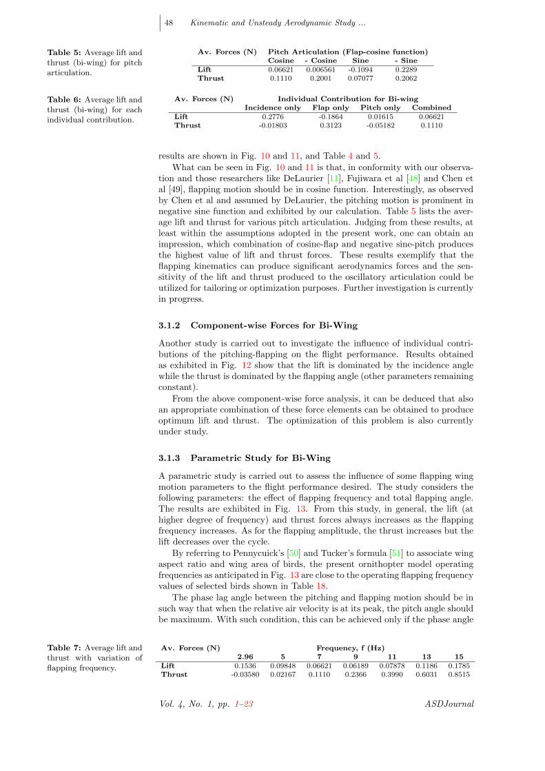
Table 5: Average lift andthrust (bi-wing) for pitcharticulation.
Av. Forces (N) Pitch Articulation (Flap-cosine function)Cosine - Cosine Sine - Sine
Lift 0.06621 0.006561 -0.1094 0.2289Thrust 0.1110 0.2001 0.07077 0.2062
Table 6: Average lift andthrust (bi-wing) for eachindividual contribution.
Av. Forces (N) Individual Contribution for Bi-wingIncidence only Flap only Pitch only Combined
Lift 0.2776 -0.1864 0.01615 0.06621Thrust -0.01803 0.3123 -0.05182 0.1110
results are shown in Fig. 10 and 11, and Table 4 and 5.
What can be seen in Fig. 10 and 11 is that, in conformity with our observa-tion and those researchers like DeLaurier [11], Fujiwara et al [48] and Chen etal [49], flapping motion should be in cosine function. Interestingly, as observedby Chen et al and assumed by DeLaurier, the pitching motion is prominent innegative sine function and exhibited by our calculation. Table 5 lists the aver-age lift and thrust for various pitch articulation. Judging from these results, atleast within the assumptions adopted in the present work, one can obtain animpression, which combination of cosine-flap and negative sine-pitch producesthe highest value of lift and thrust forces. These results exemplify that theflapping kinematics can produce significant aerodynamics forces and the sen-sitivity of the lift and thrust produced to the oscillatory articulation could beutilized for tailoring or optimization purposes. Further investigation is currentlyin progress.
3.1.2 Component-wise Forces for Bi-Wing
Another study is carried out to investigate the influence of individual contri-butions of the pitching-flapping on the flight performance. Results obtainedas exhibited in Fig. 12 show that the lift is dominated by the incidence anglewhile the thrust is dominated by the flapping angle (other parameters remainingconstant).
From the above component-wise force analysis, it can be deduced that alsoan appropriate combination of these force elements can be obtained to produceoptimum lift and thrust. The optimization of this problem is also currentlyunder study.
3.1.3 Parametric Study for Bi-Wing
A parametric study is carried out to assess the influence of some flapping wingmotion parameters to the flight performance desired. The study considers thefollowing parameters: the effect of flapping frequency and total flapping angle.The results are exhibited in Fig. 13. From this study, in general, the lift (athigher degree of frequency) and thrust forces always increases as the flappingfrequency increases. As for the flapping amplitude, the thrust increases but thelift decreases over the cycle.
By referring to Pennycuick’s [50] and Tucker’s formula [51] to associate wingaspect ratio and wing area of birds, the present ornithopter model operatingfrequencies as anticipated in Fig. 13 are close to the operating flapping frequencyvalues of selected birds shown in Table 18.
The phase lag angle between the pitching and flapping motion should be insuch way that when the relative air velocity is at its peak, the pitch angle shouldbe maximum. With such condition, this can be achieved only if the phase angle
Table 7: Average lift andthrust with variation offlapping frequency.
Av. Forces (N) Frequency, f (Hz)2.96 5 7 9 11 13 15
Lift 0.1536 0.09848 0.06621 0.06189 0.07878 0.1186 0.1785Thrust -0.03580 0.02167 0.1110 0.2366 0.3990 0.6031 0.8515
Vol. 4, No. 1, pp. 1–23 ASDJournal

H.Djojodihardjo, A.S.S.Ramli, M.A.A.Bari∣∣∣ 49
Av. Forces (N) Flapping Amplitude, β ()20 30 40 50 60 70 80
Lift 0.1976 0.1606 0.1252 0.09623 0.06621 0.03899 0.01668Thrust -0.06182 -0.04379 -0.01122 0.04039 0.1110 0.2053 0.3287
Table 8: Average lift andthrust with variation offlapping amplitude.
Figure 13: Parametricstudy on the influenceof flapping frequencyand flapping amplitudeon cyclic lift and thrust(bi-wing, semi-ellipticalplanform).
is π/2 (90). Table 9 shows the value for both average values of lift and thrustforces and it is in agreement with the statement above.
4 Analysis and Results for Quad-Wing
For the quad-wing kinematics and aerodynamics, the present work takes intoaccount the influence of the fore-wing induced downwash on the hind-wing effec-tive angle of attack. This effect is modeled by assuming that, at any instant, thecirculation Γ of the fore-wing acts at its quarter-chord point, and the induceddownwash is calculated at the three quarter-chord point of the hind-wing, asdepicted in Fig. 16.
Following Kutta-Joukowski Law, the instantaneous equivalent circulationgenerated by the fore-wing is given by
Γ =Lfore
ρU∞(36)
and the induced velocity Vi , following Biot-Savart law is given by
Vi =Γ
2πd(37)
Following Fig. 16, for small angle of attack, the induced angle is formulatedas
αinduced ≈ViU∞
(38)
Therefore the pitching angle of the hind-wing is given by
θhindwing(t) = θ0hindwingcos(ωt+ φ)− Vi
U+ θfphindwing
Figure 14: Lift andthrust variation withphase lag angle.
ASDJournal (2016) Vol. 4, No. 1, pp. 1–23

∣∣∣ 50 Kinematic and Unsteady Aerodynamic Study ...
Table 9: Average lift andthrust variation with lagof phase angle.
Av. Forces (N) Pitch and Flap phase lag0 π/4 π/2 3π/4 π
Lift 0.06621 0.1877 0.2289 0.1619 0.005574Thrust 0.1110 0.1571 0.2063 0.2263 0.1991
Figure 15: Kinematicsvariation with phase lagangle.
Figure 16: Schematicdiagram of the fore wingdownwash and the in-duced angle of attack onthe hind wing.
Vol. 4, No. 1, pp. 1–23 ASDJournal

H.Djojodihardjo, A.S.S.Ramli, M.A.A.Bari∣∣∣ 51
Figure 17: Left: Liftand thrust for quad-wingornithopter; Right: Qual-itative investigation withWang & Russell [20].
Figure 18: Flapping &pitching kinematics forFore-wing & Hind-wing.
The analysis is then carried out for the quad-wing with similar wing geom-etry as for the bi-wing. Initial initiative was done with an assumption that thefore- and hind-wings are closely attached; meaning of inexistence of gap betweenthe leading edge of the hind-wing and the trailing edge of the fore-wing. Theresults for quad-wing configuration below are obtained using the same wing ge-ometry and parameters used in bi-wing case, for fore- (front) wing and hind-(latter) wings. The results are compared and analyzed to appreciate the influ-ence of physical refinements in the computational procedure and for validationpurposes. This analysis also accounts for the induced angle of attack on thehind-wing due to downwash of the fore-wing. The results are presented in Figs.17 and 18, and Table 10.
Fig. 17 compares the lift computed using the present model to Wang andRussell’s more elaborate model calculation [20]. This comparison is very qual-itative, for proof of concept considerations. Fig. 18 shows the default motionsof flapping and pitching for both fore-wing and hind-wing, which are in cosinefunction.
4.1 Variation of Oscillatory Articulation of the Quad-Wing
Following the procedure and parametric study carried out for bi-wing ornithopter,the present study also addresses the flapping kinematics accordingly, by takinginto considerations what has been learned from bi-wing parametric study. Thefore-wing and hind-wing are arranged in tandem without gap, so that the lead-ing edge of the hind-wing touches the trailing edge of the forewing, and they are
Forces (N) Present Work Fore-wing Hind-wing Ref.[20]Average Lift 0.1193 0.0662 0.0531 1.136567Average Thrust 0.2248 0.1110 0.1138 -
Table 10: Average liftand thrust for presentwork.
ASDJournal (2016) Vol. 4, No. 1, pp. 1–23

∣∣∣ 52 Kinematic and Unsteady Aerodynamic Study ...
Figure 19: Lift andthrust for quad-wingornithopter for each flap-ping kinematics definition(pitching motion in cosinefunction).
Table 11: Average liftand thrust for quad-wingornithopter for each flap-ping kinematics definition(pitching motion in cosinefunction).
Av. Forces (N) Quadwing (Hind-wing Art.)(Fore-wing in cosine function)
Cosine - Cosine Sine - SineLift 0.1193 0.0828 0.2719 -0.0376Thrust 0.2248 0.3103 0.3307 0.1706
moving simultaneously. The flapping and pitching motions of both forewing andhind-wing are varied following negative cosine, sine and negative sine functions.The results, as exhibited in Fig. 19 and Table 11, show that the synchronous(in-phase) sinusoidal pitching and flapping produce the maximum average val-ues of lift and thrust. Table 12 and 13 show the articulation of kinematicsin pitching and flapping, for lift and thrust forces respectively. These resultsalso indicate variation of such oscillatory articulation possibilities that could befurther tailored to meet certain objectives.
4.2 Component-wise Forces for Quad-Wing
Individual contributions of the pitching-flapping motion on the flight perfor-mance are assessed. The calculation is performed on semi-elliptical wing. Re-sults obtained as exhibited in Fig. 20 and Table 14 depict similar behavior tothe bi-wing cases that the lift is dominated by the incidence angle. For thethrust, the flapping motion has a very dominant influence over the force.
From the component-wise force analysis, it can be summarized that also asuitable combination of these force elements can be attained in order to generateoptimum lift and thrust. The optimization of this problem is also currently beingstudied.
4.3 Parametric Study for Quad-Wing
A parametric study is carried out to assess the influence of certain flappingwing motion parameters to the flight performance desired. The study considersthe following parameters: the effect of flapping frequency and the gap distancebetween fore-wing and hind-wing. The results are exhibited in Fig. 21, Table15 and 16. It can be seen that the effect of flapping frequency exhibits similartrend as bi-wing’s. For the gap distance effect, as the distance increases, the liftincreases but the thrust decreases in small magnitude.
Results obtained as exhibited in Fig. 22 show the lift produced for variousscenarios involving phase combinations between flapping and pitching motions
Table 12: Average liftfor quad-wing ornithopterfor each pitching andflapping kinematicsdefinition.
Av. Lift (N) FLAP (Hind-wing)FLAP (Fore-wing) Cosine - Cosine Sine - Sine
Cosine 0.1193 0.0828 0.2719 -0.0376- Cosine 0.0979 0.0605 0.2513 -0.0640Sine 0.2587 0.2238 0.4045 0.1014- Sine -0.0138 -0.0536 0.1452 -0.1762
Vol. 4, No. 1, pp. 1–23 ASDJournal

H.Djojodihardjo, A.S.S.Ramli, M.A.A.Bari∣∣∣ 53
Av. Thrust (N) FLAP (Hind-wing)FLAP (Fore-wing) Cosine - Cosine Sine - Sine
Cosine 0.2248 0.3103 0.3307 0.1706- Cosine 0.3075 0.3924 0.4138 0.2526Sine 0.3358 0.4238 0.4460 0.2785- Sine 0.1624 0.2457 0.2625 0.1097
Table 13: Averagethrust for quad-wingornithopter for eachpitching and flappingkinematics definition.
Figure 20: Component-wise contribution forquad-wing.
Av. Forces (N) Individual Contribution for Quad-wingIncidence only Flap only Pitch only Combined
Lift 0.5052 -0.3412 0.0293 0.1193Thrust -0.0329 0.6162 -0.1036 0.2248
Table 14: Averagelift and thrust (quad-wing) for each individualcontribution.
Figure 21: Parametricstudy on the influenceof flapping frequencyand gap distance be-tween fore-wing andhind-wing on cyclic liftand thrust (quad-wing,semi-elliptical planform).
ASDJournal (2016) Vol. 4, No. 1, pp. 1–23

∣∣∣ 54 Kinematic and Unsteady Aerodynamic Study ...
Figure 22: Fore flappingphase lag variation forQuad-wing.
Table 15: Average liftand thrust with variationof flapping frequency.
Av. Forces (N) Flapping Freq., f (Hz)2.96 5 7 9 11 13 15
Lift 0.294 0.182 0.119 0.107 0.128 0.187 0.277Thrust -0.065 0.047 0.225 0.476 0.802 1.215 1.718
of the individual fore- and hind-wings. Table 17 summarizes the average forcesper cycle for the selected scenarios.
A deduction can be made from the results from Table 17 that having in-phaseflight produces the maximum lift and thrust, among the others. In conformitywith the observation by Deng & Hu [52] and Alexander [53] in their study, thepresent study also indicates that when quad-wing insect like dragonfly performsaggressive maneuvers, they will employ in-phase flight to generate larger aero-dynamic forces. However further analysis to optimize the combination of theseparameters is still under progress.
5 Comprehensive Assessment of Modeling Results
Better understanding of the production of lift and thrust are intended for cur-rent simplified modeling of both bi-wing and quad-wing ornithopters. It is alsomeant to build a comprehensive foundation and act as a guideline to developa simple experimental model ornithopter. A more sophisticated computationaland experimental prototype can be built in a progressive manner by super-posing other significant characteristics. To gain better comprehension into thekinematic and aerodynamic modelling of bi-wing and quad-wing ornithopters,comparison will be made on the basic characteristics and performance of selectedornithopter models with those of selected real birds and insects.
The use of CFD computation to simulate the vorticity field for quad-wing isa complex study as reported by Wang and Russell [20]. Although on average,an upward net force is generated on the wing due to the downward flow createdby the wing motion, the computation is not readily related to the computa-tional results for lift and thrust. For future progress, such result could be thebasis platform to the present aerodynamics and kinematics modeling of non-deforming quad-wing ornithopter, which can extensively and progressively befurther redeveloped and refined to approach the genuine living biosystem flightfeatures, such as those of dragonfly and other related enthomopters.
For this purpose, Table 18 has been prepared as an extension of the earlierTable presented in [26], to obtain an insight of the flight characteristics and basicperformance of ornithopter and entomopter models, and birds and insect. Table18 exhibits the ratio of the lift per cycle, thrust per cycle, lift per aspect ratio and
Table 16: Average liftand thrust with variationof gap distance (expressedin chords) between fore-wing and hind-wing.
Av. Forces (N) Distance, dNo Gap 1/2 c 1 c 1.5 c 2 c
Lift 0.1193 0.1227 0.1247 0.1260 0.1270Thrust 0.2248 0.2241 0.2237 0.2234 0.2232
Vol. 4, No. 1, pp. 1–23 ASDJournal

H.Djojodihardjo, A.S.S.Ramli, M.A.A.Bari∣∣∣ 55
Av. Forces (N) phase lag of fore-wing flapping motion(Fore- & Hind-wing in cosine function)
0 π/4 π/2 3π/4 πLift 0.1193 0.0123 -0.0376 -0.0208 0.0847Thrust 0.2248 0.1792 0.1706 0.2312 0.3107
Table 17: Average liftand thrust with variationof flapping phase lag forfore-wing.
Table 18: Comparisonof basic performance ofornithopter models andbirds (extended from ear-lier work [25, 26, 54]).
the wing loading calculated using the present simplified computational modeland those obtained by other investigators; for comparison, the weight per wing-span of a selected sample of birds are also exhibited. Although the comparison isby no means rigorous, it may shed some light on how the geometrical modellingand the flapping motion considered in the computational model may contributeto the total lift produced and how further refinement could be synthesized.
The development carried out in this work is addressed to biomimicry ofbiosystem flying in the Reynolds number range of 1.0 × 10⁴ to 1.0 × 10⁵ whichis turbulent. The projected ornithopter and MAV will be also operating inthis range of Reynolds number. The aerodynamics that have been adopted inthe present work takes into account viscous correction appropriately (DeLaurier[11], Shyy et al. [7]). Shyy et al [7] show that for all airfoils, the CL/CD ratioexhibits a clear Reynolds number dependency. For Re varying between 7.5×10⁴
and 2.0×10⁶, CL/CD changes by a factor of 2 to 3 for the airfoils tested.In the present work, viscosity effects are taken into account following the
approach and results of DeLaurier [11], using the computational formulation asgiven in the present paper as a simplified approach to the problem, but vali-dated through comparison with comparable experimental results range. Suchapproach can be justified as a preliminary step towards more accurate approachand to develop simple flapping ornithopter MAV.
6 Conclusions
The present work has been performed to assess the effect of flapping-pitchingmotion with pitch-flap phase lag in the flight of ornithopter. In this conjunc-tion, a computational model has been considered, and a generic computational
ASDJournal (2016) Vol. 4, No. 1, pp. 1–23

∣∣∣ 56 Kinematic and Unsteady Aerodynamic Study ...
method has been adopted, utilizing strip theory and two-dimensional unsteadyaerodynamic theory of Theodorsen with modifications to account for three-dimensional and viscous effects and leading edge suction. The study is carriedout on semi-elliptical wing planforms. The results have been compared andvalidated with other literatures within similar unsteady aerodynamic approachand general physical data, and within the physical assumptions limitations; en-couraging qualitative agreements or better have been indicated, which meetthe proof of concept objectives of the present work. For the bi-wing flappingornithopter, judging from lift per unit span, the present flapping-wing modelperformance is comparable to those studied by Yu et al [47]. The analysis andsimulation by splitting the flapping and pitching motion shows that: (a) Thelift is dominantly produced by the incidence angle (b) The thrust is dominatedby flapping motion (c) Phase-lag could be utilized to obtain optimum lift andthrust for each wing configurations.
For the quad-wing ornithopter, at the present stage, the simplified compu-tational model adopted verified the gain in lift obtained as compared to bi-wingflapping ornithopter, in particular by the possibility of varying the phase lagbetween the flapping and pitching motion of individual wing as well as betweenthe fore- and hind-wings. A structured approach has been followed to assessthe effect of different design parameters on lift and thrust of an ornithopter, aswell as the individual contribution of the component of motion. These resultslend support to the utilization of the generic modelling adopted in the synthesisof a flight model, although more refined approach should be developed. Vari-ous physical elements could be considered to develop ornithopter kinematic andaerodynamic modelling, as well as using more refined aerodynamic computa-tion, such as CFD or lifting surface methods. In retrospect, a generic physicaland computational model based on simple kinematics and basic aerodynamicsof a flapping-wing ornithopter has been demonstrated to be capable of reveal-ing its basic characteristics and can be utilized for further development of aflapping-wing MAV. Application of the present kinematic, aerodynamic andcomputational approaches shed some light on some of the salient aerodynamicperformance of the quad-wing ornithopter.
Acknowledgements
The authors would like to thank University Putra Malaysia (UPM) for grant-ing Research University Grant Scheme (RUGS) Project Code: 9378200, underwhich the present research is carried out.
References
[1] S. Ho, H. Nassef, N. Pornsinsirirak, Y.-C. Tai, and C.-M. Ho. UnsteadyAerodynamics and Flow Control for Flapping Wing Flyers. Progress inAerospace Sciences 39: 635–681, 2003.
[2] T. Weis-Fogh. Quick Estimates of Flight Fitness in Hovering Animals,Including Novel Mechanisms for Lift Production. Journal of ExperimentalBiology 5: 169–230, 1973.
[3] C. P. Ellington. The Aerodynamics of Hovering Insect Flight, III. Kine-matics. Phil. Trans. R. Soc. London B 305: 41-78, 1984.
[4] C. P. Ellington. The Novel Aerodynamics of Insect Flight: Applicationsto Micro-Air Vehicles. Journal of Experimental Biology 202: 3439–3448,1999.
[5] C. P. Ellington. The Aerodynamics of Hovering Insect Flight, I, Quasi-Steady Analysis. Phil. Trans. R. Soc. London B 305: 1-15, 1984.
Vol. 4, No. 1, pp. 1–23 ASDJournal

H.Djojodihardjo, A.S.S.Ramli, M.A.A.Bari∣∣∣ 57
[6] W. Shyy, M. Berg, and D. Ljungqvist. Flapping and Flexible Wings forBiological and Micro Air Vehicles. Progress in Aerospace Sciences 35:455-505, 1999.
[7] W. Shyy, H. Aono, S. K. Chimakurthi, P. Trizila, C.-K. Kang, C. E. S.Cesnik, and H. Li. Recent Progress in Flapping Wing Aerodynamics andAeroelasticity. Progress in Aerospace Science 46(7), 284-327, 2010.
[8] M. H. Dickinson, F.-O. Lehmann, and S. P. Sane. Wing Rotation and theAerodynamic Basis of Insect Flight. Science 284(5422): 1954-1960, 1999.
[9] R. Zbikowski. On Aerodynamic Modelling of an Insect-like Flapping Wingin hover for Micro Air Vehicles. Phil. Trans. R. Soc. London A 360: 273-290, 2002.
[10] S. A. Ansari, R. Zbikowski, K. Knowles. Aerodynamic Modelling of Insect-like Flapping Flight for Micro Air Vehicles. Progress in Aerospace Sciences42: 129–172, 2006.
[11] J. D. DeLaurier. An Aerodynamic Model for Flapping Wing Flight. Aero-nautical Journal of the Royal Aeronautical Society 97: 125-130, 1993.
[12] Z. J. Wang. The Role of Drag in Insect Hovering. Journal of ExperimentalBiology 207: 4147- 4155, 2004.
[13] Z. J. Wang. Dissecting Insect Flight. Annu. Rev. Fluid Mech. 37:183–210, 2005.
[14] N. C. Rosenfeld. An Analytical Investigation of Flapping Wing Structuresfor MAV. Ph.D. Thesis, University of Maryland, 2011.
[15] B. Nicholson, S. Page, H. Dong, and J. Slater. Design of a FlappingQuad-Winged Micro Air Vehicle. AIAA-4337, 2007.
[16] W. J. Maybury, and F.-O. Lehmann. The Fluid Dynamics of FlightControl by Kinematic Phase Lag Variation Between Two Robotic InsectWings. Journal of Experimental Biology 207: 4707-4726, 2004.
[17] J. Ratti. QV-The Quad Winged, Energy Ef?cient, Six Degree of FreedomCapable Micro Air Vehicle. PhD Thesis, Georgia Institute of Technology,2011.
[18] D. T. Prosser. Flapping Wing Design for a Dragon-fly like MAV. M.Sc.Thesis, Rochester Institute of Technology, 2011.
[19] K. A. Strang. Efficient Flapping Flight of Pterosaurs. PhD Thesis, Stan-ford University, 2009.
[20] Z. J. Wang, and D. Russell. Effect of Forewing and Hindwing Interactionson Aerodynamic Forces and Power in Hovering Dragonfly Flight. PhysicalReview Letters 99(148101), 2007.
[21] H. E. Taha, M. R. Hajj, and A. H. Nayfeh. Flight Dynamics and Controlof Flapping Wing MAV - A Review. Nonlinear Dynamics 70: 907–939,2012.
[22] H. E. Taha, M. R. Hajj, and P. S. Beran. State-Space Representationof the Unsteady Aerodynamics of Flapping Flight. Aerospace Science &Technology 34: 1-11, 2014.
[23] U. M. Norberg. Hovering Flight of Plecotusauritus, L. Bijdr. Dierk 40,62-66 (Proc.2nd int. Bat. Res, Conf.), 1970.
ASDJournal (2016) Vol. 4, No. 1, pp. 1–23

∣∣∣ 58 Kinematic and Unsteady Aerodynamic Study ...
[24] R. Tedrake, Z. Jackowski, R. Cory, J. W. Roberts, and W. Hoburg. Learn-ing to Fly like a Bird. Communications of the ACM, 2009.
[25] H. Djojodihardjo, A. S. S. Ramli, and S. Wiriadidjaja. Kinematic andAerodynamic Modeling of Flapping Wing Ornithopter. Procedia Engi-neering (Elsevier) 50: 848-863, 2012.
[26] H. Djojodihardjo, and A. S. S. Ramli. Kinematic and Unsteady Aerody-namic Modelling, Numerical Simulation and Parametric Study Of Flap-ping Wing Ornithopter. Proceedings, International Forum on Aeroelas-ticity and Structural Dynamics, Bristol, 2013.
[27] A. R. Jones, N. A. Bakhtian, and H. Babinsky. Low Reynolds NumberAerodynamics of Leading-edge Flaps. Journal of Aircraft 45(1): 342-345,2008.
[28] H. Djojodihardjo, and M. A. A. Bari. Kinematic and Unsteady Aerody-namic Modelling of Flapping Bi- and Quad-Wing Ornithopter. Proceedings-ICAS 2014, Paper 2014-0433, 2014.
[29] T. Theodorsen. General Theory of Aerodynamic Instability and the Mech-anism of Flutter. NACA Report No.496, 1935.
[30] R. T. Jones. The Unsteady Lift of a Wing of Finite Aspect Ratio. NACAReport No.681, 1940.
[31] E. C. Polhamus. A Concept of the Vortex Lift of Sharp-Edge Delta WingsBased On A Leading-Edge-Suction Analogy. NASA TN D-3767, 1966.
[32] E. C. Polhamus. Application of the Leading-Edge-Suction Analogy OfVortex Lift To The Drag Due To Lift Of Sharp-Edge Delta Wings. NASATN D-4739, 1968.
[33] H. Ashley, M. T. Landahl, and S. E. Widnall. New Directions in LiftingSurface Theory. AIAA Journal 3(1), 1965.
[34] A. Albano, and W. P. Rodden. A Doublet-Lattice Method for Calculat-ing Lift Distributions on Oscillating Surfaces in Subsonic Flows. AIAAJournal 7(2): 279-285, 1969.
[35] R. H. Djojodihardjo, and S. E. Widnall. A Numerical Method for the Cal-culation of Nonlinear, Unsteady Lifting Potential Flow Problems. AIAAJournal 7(10): 2001-2009, 1969.
[36] J. Murua, R. Palacios, and J. M. R. Graham. Applications of the UnsteadyVortex-Lattice Method in Aircraft Aeroelasticity and Flight Dynamics.Progress in Aerospace Sciences 55: 46-72, 2012.
[37] H. Djojodihardjo, A. S. S. Ramli, and S. Wiriadidjaja. Generic Modellingand Parametric Study of the Aerodynamic Characteristics of FlappingWing Micro-Air-Vehicle. Applied Mech. and Materials 225: 18-25, 2012.
[38] H. Djojodihardjo, M. A. A. Bari, A. S. M. Rafie, and S. Wiriadidjaja.Further Development of the Kinematic and Aerodynamic Modeling andAnalysis of Flapping Wing Ornithopter from Basic Principles. AppliedMech. and Materials 629: 9-17, 2014.
[39] R. L. Harmon. Aerodynamic Modelling of a Flapping Membrane WingUsing Motion Tracking Experiments. M.Sc. Thesis, University of Mary-land, 2008.
[40] J. O. Scherer. Experimental and Theoretical Investigation of Large Am-plitude Oscillating Foil Propulsion Systems. Hydronautics, Laurel, Md,1968.
Vol. 4, No. 1, pp. 1–23 ASDJournal

H.Djojodihardjo, A.S.S.Ramli, M.A.A.Bari∣∣∣ 59
[41] H. Multhopp. Methods for Calculating the Lift Distribution of Wings(Subsonic Lifting-Surface Theory). ARC R&M No.2884, 1955.
[42] I. E. Garrick. Propulsion of a Flapping and Oscillating Aerofoil. NACAReport No.567, 1936.
[43] I. E. Garrick. On Some Reciprocal Relations in the Theory of Nonstation-ary Flows. NACA Report No.629, 1938.
[44] A. M. Kuethe, and C.-Y. Chow. The Finite Wing, Foundations of Aero-dynamics. Fourth edition, John Wiley, New York: 145-164, 1986.
[45] J. D. Anderson. Fundamentals of Aerodynamics. Fourth edition, McGraw-Hill, New York, 2004.
[46] M. Y. Zakaria, H. E. Taha, M. R. Hajj. Shape and Kinematic DesignOptimization of Pterosaur Replica. AIAA 2014-2869, 2014.
[47] C. Yu, D. Kim, and Y. Zhao. Lift and Thrust Characteristics of Flap-ping Wing Aerial Vehicle with Pitching and Flapping Motion. Journal ofApplied Mathematics and Physics 2: 1031-1038, 2014.
[48] T. Fujiwara, K. Hirakawa, S. Okuma, T. Udagawa, S. Nakano, and K.Kikuchi. Development of a Small Flapping Robot: Motion Analysis Dur-ing Takeoff by Numerical Simulation and Experiment. Mechanical Sys-tems and Signal Processing 22(6): 1304-1315, 2008.
[49] M. W. Chen, Y. L. Zhang, and M. Sun. Wing and Body Motion andAerodynamic and Leg Forces During Take-off in Droneflies. Journal ofthe Royal Society Interface 10, 2013.
[50] C. J. Pennycuick. Predicting Wingbeat Frequency and Wavelength ofBirds. Journal of Experimental Biology 150: 171-185, 1990.
[51] V. A. Tucker. Gliding Birds: The Effect of Variable Wing Span. J. Exp.Biology 133, 1987.
[52] X. Deng, and Z. Hu. Wing-wing Interactions in Dragonfly Flight. APublication of Ine-Web.Org, 10.2417/1200811.1269, 2008.
[53] D. E. Alexander. Unusual Phase Relationships between the Forewings andHindwings in Flying Dragonflies. J. Exp. Biology 109: 379-383, 1984.
[54] H. Djojodihardjo, A. S. S. Ramli, M. S. A. Aziz, and K. A. Ahmad.Numerical Modelling, Simulation and Visualization of Flapping Wing Or-nithopter. Keynote Address, International Conference on Engineering Ma-terials and Processes (ICEMAP), Chennai, 2013.
[55] M. A. Malik, and F. Ahmad. Effect of Different Design Parameters on Lift,Thrust, and Drag of an Ornithopter. Proceedings of the World Congresson Engineering 2010 Vol. II, London, U.K., 2010.
[56] K. Byl. A Passive Dynamic Approach for Flapping Wing Micro AerialVehicle Control. ASME Dynamic Systems and Controls Conference, 2010.
ASDJournal (2016) Vol. 4, No. 1, pp. 1–23