kinematics and kinetics of rigidbodies
TRANSCRIPT
8/21/2019 Kinematics and kinetics of rigidbodies
http://slidepdf.com/reader/full/kinematics-and-kinetics-of-rigidbodies 1/190
CHAPTER 8. KINEMATICS AND KINETICS OF RIGID BODIES IN
THREE-DIMENSIONAL MOTION 8.1. SPHERICAL COORDINATES
8.1 Spherical Coordinates
Excerpts from this work may be reproduced by instructors for distribution on a not-for-profit basis for testing or instructional purposes only to students enrolled in courses for which the textbook has been adopted. Any other reproduction or translation of this work beyond that permitted by Sections 107 or 108 of the 1976 United States
Copyright Act without the permission of the copyright owner is unlawful.
35

8/21/2019 Kinematics and kinetics of rigidbodies
http://slidepdf.com/reader/full/kinematics-and-kinetics-of-rigidbodies 2/190
8.2. ANGULAR VELOCITY OF RIGID BODIES IN THREE-DIMENSIONAL MOTION
CHAPTER 8. KINEMATICS AND KINETICS OF RIGID BODIES IN
THREE-DIMENSIONAL MOTION
8.2 Angular Velocity of Rigid Bodies in Three-Dimensional Mo-
tion
Excerpts from this work may be reproduced by instructors for distribution on a not-for-profit basis for testing or instructional purposes only to students enrolled in courses for which the textbook has been adopted. Any other reproduction or translation of this work beyond that permitted by Sections 107 or 108 of the 1976 United States
Copyright Act without the permission of the copyright owner is unlawful.
36
8/21/2019 Kinematics and kinetics of rigidbodies
http://slidepdf.com/reader/full/kinematics-and-kinetics-of-rigidbodies 3/190
CHAPTER 8. KINEMATICS AND KINETICS OF RIGID BODIES IN
THREE-DIMENSIONAL MOTION 8.3. ANGULAR ACCELERATION OF RIGID BODIES IN THREE-DIMENSIONAL MOTION
8.3 Angular Acceleration of Rigid Bodies in Three-Dimensional
Motion
Excerpts from this work may be reproduced by instructors for distribution on a not-for-profit basis for testing or instructional purposes only to students enrolled in courses for which the textbook has been adopted. Any other reproduction or translation of this work beyond that permitted by Sections 107 or 108 of the 1976 United States
Copyright Act without the permission of the copyright owner is unlawful.
37

8/21/2019 Kinematics and kinetics of rigidbodies
http://slidepdf.com/reader/full/kinematics-and-kinetics-of-rigidbodies 4/190
8.4. GENERAL MOTION OF AND ON THREE-DIMENSIONAL BODIES
CHAPTER 8. KINEMATICS AND KINETICS OF RIGID BODIES IN
THREE-DIMENSIONAL MOTION
8.4 General Motion Of and On Three-Dimensional Bodies
Excerpts from this work may be reproduced by instructors for distribution on a not-for-profit basis for testing or instructional purposes only to students enrolled in courses for which the textbook has been adopted. Any other reproduction or translation of this work beyond that permitted by Sections 107 or 108 of the 1976 United States
Copyright Act without the permission of the copyright owner is unlawful.
38

8/21/2019 Kinematics and kinetics of rigidbodies
http://slidepdf.com/reader/full/kinematics-and-kinetics-of-rigidbodies 5/190
CHAPTER 8. KINEMATICS AND KINETICS OF RIGID BODIES IN
THREE-DIMENSIONAL MOTION 8.4. GENERAL MOTION OF AND ON THREE-DIMENSIONAL BODIES
8.4.1GOAL: Determine the angular velocity of a rotating disk.GIVEN: Inner shaft’s angular velocity and the angular velocity of the disk with respect to theshaft.DRAW:
FORMULATE EQUATIONS: We’ll use the expression for angular velocity on a rotating body.SOLVE: The angular velocity of the disk D is equal to the angular velocity of inner shaft AB plusthe relative angular velocity of disk D with respect to shaft AB. The angular velocity of AB is−ω1
, and the relative angular velocity of disk to shaft is ω2ı . Thus:
ωD = ω2ı − ω1
Excerpts from this work may be reproduced by instructors for distribution on a not-for-profit basis for testing or instructional purposes only to students enrolled in courses for which the textbook has been adopted. Any other reproduction or translation of this work beyond that permitted by Sections 107 or 108 of the 1976 United States
Copyright Act without the permission of the copyright owner is unlawful.
39

8/21/2019 Kinematics and kinetics of rigidbodies
http://slidepdf.com/reader/full/kinematics-and-kinetics-of-rigidbodies 6/190
8.4. GENERAL MOTION OF AND ON THREE-DIMENSIONAL BODIES
CHAPTER 8. KINEMATICS AND KINETICS OF RIGID BODIES IN
THREE-DIMENSIONAL MOTION
8.4.2GOAL: Determine the angular acceleration of a rotating caster.GIVEN: Angular velocity of the caster’s frame is ω1
b3 and the angular velocity of the caster with
respect to the frame is −ω2
b1.
DRAW:
FORMULATE EQUATIONS: We’ll use the expression for acceleration on a rotating body:
d
dt
N
ωC = d
dt
F
ωC + ωF ×ωC (1)
SOLVE: The caster C has a constant rotation rate with respect to the frame F and so (1) simplifiesto
d
dt
N
ωC = ωF ×ωC = ω1
b3×(−ω2
b1) = −ω1ω2
b2
αC = −ω1ω2
b2
Excerpts from this work may be reproduced by instructors for distribution on a not-for-profit basis for testing or instructional purposes only to students enrolled in courses for which the textbook has been adopted. Any other reproduction or translation of this work beyond that permitted by Sections 107 or 108 of the 1976 United States
Copyright Act without the permission of the copyright owner is unlawful.
40
8/21/2019 Kinematics and kinetics of rigidbodies
http://slidepdf.com/reader/full/kinematics-and-kinetics-of-rigidbodies 7/190
CHAPTER 8. KINEMATICS AND KINETICS OF RIGID BODIES IN
THREE-DIMENSIONAL MOTION 8.4. GENERAL MOTION OF AND ON THREE-DIMENSIONAL BODIES
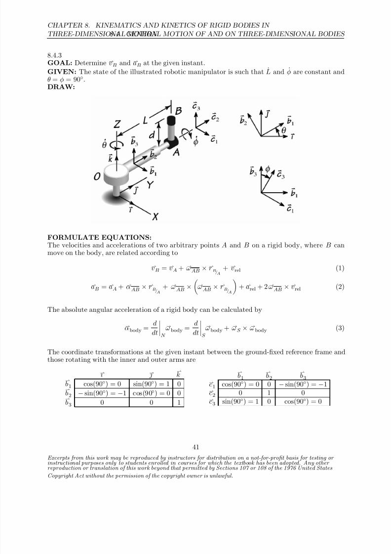
8.4.3GOAL: Determine vB and aB at the given instant.
GIVEN: The state of the illustrated robotic manipulator is such that L and φ are constant andθ = φ = 90.DRAW:
FORMULATE EQUATIONS:The velocities and accelerations of two arbitrary points A and B on a rigid body, where B canmove on the body, are related according to
vB = vA + ωAB × rB/A+ vrel (1)
aB
= aA
+ αAB ×
rB/A
+ ωAB × ω
AB ×rB/A + a
rel + 2 ω
AB ×vrel
(2)
The absolute angular acceleration of a rigid body can be calculated by
αbody = d
dt
N
ωbody = d
dt
S
ωbody + ωS × ωbody (3)
The coordinate transformations at the given instant between the ground-fixed reference frame andthose rotating with the inner and outer arms are
ı
kb1
cos(90
) = 0 sin(90
) = 1 0b2 − sin(90) = −1 cos(90) = 0 0b3 0 0 1
b1
b2
b3
c1
cos(90
) = 0 0 −
sin(90
) =−
1c2 0 1 0c3 sin(90) = 1 0 cos(90) = 0
Excerpts from this work may be reproduced by instructors for distribution on a not-for-profit basis for testing or instructional purposes only to students enrolled in courses for which the textbook has been adopted. Any other reproduction or translation of this work beyond that permitted by Sections 107 or 108 of the 1976 United States
Copyright Act without the permission of the copyright owner is unlawful.
41

8/21/2019 Kinematics and kinetics of rigidbodies
http://slidepdf.com/reader/full/kinematics-and-kinetics-of-rigidbodies 8/190
8.4. GENERAL MOTION OF AND ON THREE-DIMENSIONAL BODIES
CHAPTER 8. KINEMATICS AND KINETICS OF RIGID BODIES IN
THREE-DIMENSIONAL MOTION
SOLVE:Applying (1) to arm OA, we have that the velocity of the joint A is
Arm OA: (1) ⇒ vA = ωOA × rA/O+ vrel, A
vA = θb3
×Lb2 + L
b2
vA = −Lθb1 + L
b2
Thus, the velocity of B is given by
Arm AB: (1) ⇒ vB = vA + ωAB × rB/A
vB = −Lθb1 + L
b2 +
θb3 + φc2
× dc3
vB = −Lθb1 + L
b2 +
θb3 + φ
b2
× d
b1
vB = −Lθb1 +
L + θd
b2 − φd
b3
We find from (2) that the acceleration of A is
Arm OA: (2) ⇒ aA = αOA × rA/O+ ωOA ×
ωOA × rA/O
+ 2 ωOA × vrel, A
aA = θb3 × L
b2 + θ
b3 ×
θb3 × L
b2
+ 2θ
b3 × L
b2
aA = − Lθ + 2 Lθb1 − Lθ2
b2
Using (3), we get that the angular acceleration of the outer arm AB is given by
Arm AB: (3) ⇒ αAB = d
dt
N
ωAB = d
dt
S
ωAB + ωOA × ωAB
αAB = θb3 + θ
b3 ×
θb3 + φc2
= θ
b3 + θ
b3 × φ
b2
αAB = −θ φb1 + θ
b3
Hence, the acceleration of B is
Arm AB: (2) ⇒ aB = aA + αAB × rB/A+ ωAB ×
ωAB × rB/A
aB = −
Lθ + 2 Lθb1 − Lθ2
b2 +
−θ φ
b1 + θ
b3
× dc3 +
θb3 + φc2
×
θb3 + φc2
× dc3
Excerpts from this work may be reproduced by instructors for distribution on a not-for-profit basis for testing or instructional purposes only to students enrolled in courses for which the textbook has been adopted. Any other reproduction or translation of this work beyond that permitted by Sections 107 or 108 of the 1976 United States
Copyright Act without the permission of the copyright owner is unlawful.
42
8/21/2019 Kinematics and kinetics of rigidbodies
http://slidepdf.com/reader/full/kinematics-and-kinetics-of-rigidbodies 9/190
CHAPTER 8. KINEMATICS AND KINETICS OF RIGID BODIES IN
THREE-DIMENSIONAL MOTION 8.4. GENERAL MOTION OF AND ON THREE-DIMENSIONAL BODIES
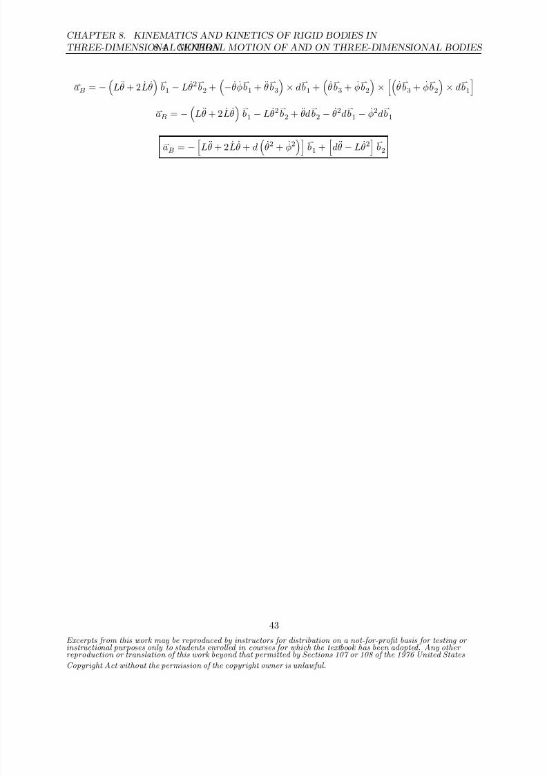
aB = −
Lθ + 2 Lθb1 − Lθ2
b2 +
−θ φ
b1 + θ
b3
× d
b1 +
θb3 + φ
b2
×
θb3 + φ
b2
× d
b1
aB = −
Lθ + 2 Lθ
b1 − Lθ2
b2 + θd
b2 − θ2d
b1 − φ2d
b1
aB = −
Lθ + 2 Lθ + d
θ2 + φ2
b1 +
dθ − Lθ2
b2
Excerpts from this work may be reproduced by instructors for distribution on a not-for-profit basis for testing or instructional purposes only to students enrolled in courses for which the textbook has been adopted. Any other reproduction or translation of this work beyond that permitted by Sections 107 or 108 of the 1976 United States
Copyright Act without the permission of the copyright owner is unlawful.
43

8/21/2019 Kinematics and kinetics of rigidbodies
http://slidepdf.com/reader/full/kinematics-and-kinetics-of-rigidbodies 10/190
8.4. GENERAL MOTION OF AND ON THREE-DIMENSIONAL BODIES
CHAPTER 8. KINEMATICS AND KINETICS OF RIGID BODIES IN
THREE-DIMENSIONAL MOTION
8.4.4GOAL: Determine the angular velocity and acceleration of one arm of the illustrated mechanism.GIVEN: Constant angular velocity of inner arm, and constant angular velocity of outer arm withrespect to inner armDRAW: The figure shows the mechanism with the original coordinate axes and some newly at-
tached unit vectors. Unit vectors
ı ,
,
k are aligned with the ground-fixed X,Y,Z axes. Unitvectors b1,
b2,
b3 are attached to the inner arm OA.
FORMULATE EQUATIONS: We’ll use the expressions for angular velocity and accelerationon a rotating body.SOLVE: The angular velocity of arm AB is equal to the angular velocity of arm OA plus therelative angular velocity of arm AB with respect to arm OA. The angular velocity of OA is ψ
k ,
and the relative angular velocity of AB with respect to OA is −θb2. Thus:
ωAB = ψ
k − θ
b2 (1)
This can be written is the b -frame as:
ωAB = ψ
b3 − θ
b2
To determine the angular acceleration of AB we can differentiate (1):
αAB = d
dtωAB =
d
dt
ψk − θ
b2
= ψ
k
=0
+ ψ
d
dt
k
=0
− θb2
=0
−θ
d
dt
b2
Since the angular speeds are constant, andk is fixed in space, the only term remaining is −θ
ddt
b2
.
The tip of unit vector b2 sweeps in the −
b1 direction with speed ψ. So we have:
αAB = −θ
d
dt
b2
= −θ ψ(−
b1)
Excerpts from this work may be reproduced by instructors for distribution on a not-for-profit basis for testing or instructional purposes only to students enrolled in courses for which the textbook has been adopted. Any other reproduction or translation of this work beyond that permitted by Sections 107 or 108 of the 1976 United States
Copyright Act without the permission of the copyright owner is unlawful.
44

8/21/2019 Kinematics and kinetics of rigidbodies
http://slidepdf.com/reader/full/kinematics-and-kinetics-of-rigidbodies 11/190
CHAPTER 8. KINEMATICS AND KINETICS OF RIGID BODIES IN
THREE-DIMENSIONAL MOTION 8.4. GENERAL MOTION OF AND ON THREE-DIMENSIONAL BODIES
αAB = θ ψ
b1
Alternatively, we could have used the expression:
d
dtωAB =
d
dt
S
ωAB + ωOA
×ωAB
= 0 + ψ
k ×( ψ
k − θ
b2) = θ ψ
b1
Excerpts from this work may be reproduced by instructors for distribution on a not-for-profit basis for testing or instructional purposes only to students enrolled in courses for which the textbook has been adopted. Any other reproduction or translation of this work beyond that permitted by Sections 107 or 108 of the 1976 United States
Copyright Act without the permission of the copyright owner is unlawful.
45

8/21/2019 Kinematics and kinetics of rigidbodies
http://slidepdf.com/reader/full/kinematics-and-kinetics-of-rigidbodies 12/190
8.4. GENERAL MOTION OF AND ON THREE-DIMENSIONAL BODIES
CHAPTER 8. KINEMATICS AND KINETICS OF RIGID BODIES IN
THREE-DIMENSIONAL MOTION
8.4.5GOAL: Determine the angular velocity and acceleration of one wheel of the illustrated mechanism.GIVEN: Angular velocity of the three-armed body is given by ωT = 2 rad/s. h = 0.1m andr = 0.004m.DRAW: The figure shows the mechanism with ground-fixed ı , ,
k unit vectors as well
b1,
b2,
b3
(fixed to the rotating body T ).
ASSUME: We’ll assume that the wheels roll without slip on the bottom of the microwave oven.FORMULATE EQUATIONS: We’ll use the expressions for angular velocity and accelerationon a rotating body.SOLVE: The angular velocity of the wheel A is equal to the angular velocity of arm three-armbody (T ) plus the relative angular velocity of wheel A with respect to the body. The angular
velocity of the three arm body is 2 rad/s = 2b2 rad/s ( and
b2 are identical for this problem).
The wheel rolls without slip and can find the wheel’s angular velocity by determining the speed of the wheel A’s center (GA) and then using
vC = vG A + ωA×r
C /G A
Applying the no-slip constraint that vC = 0 will get us the angular velocity information we need.We’ll assume that the wheel A is rotating with respect to T with angular speed φ.
vA = (2b2 rad/s)×(0.1
b1 m) = −0.2
b3 m/s
vC = vA + vC /A
= −0.2b3 m/s + ωA×(−r
b2)
= −0.2b3 m/s + ( φ
b1 + 2
b2)×(−r
b2)
= −0.2b3 m/s − r φ
b3
Applying the no-slip constraint that vC = 0 gives us
φ =
−
0.2m/s
r
=
−
0.2m/s
0.004m
=
−50 rad/s
Thus we haveωA = (−50
b1 + 2
b2) rad/s
αA = d
dt (ωA) =
−50
d
dt
b1 + 2
d
dt
b2
rad/s =
−50(−2
b3 rad/s)
rad/s
Excerpts from this work may be reproduced by instructors for distribution on a not-for-profit basis for testing or instructional purposes only to students enrolled in courses for which the textbook has been adopted. Any other reproduction or translation of this work beyond that permitted by Sections 107 or 108 of the 1976 United States
Copyright Act without the permission of the copyright owner is unlawful.
46

8/21/2019 Kinematics and kinetics of rigidbodies
http://slidepdf.com/reader/full/kinematics-and-kinetics-of-rigidbodies 13/190
CHAPTER 8. KINEMATICS AND KINETICS OF RIGID BODIES IN
THREE-DIMENSIONAL MOTION 8.4. GENERAL MOTION OF AND ON THREE-DIMENSIONAL BODIES
αA = 100b3 rad/s2
Excerpts from this work may be reproduced by instructors for distribution on a not-for-profit basis for testing or instructional purposes only to students enrolled in courses for which the textbook has been adopted. Any other reproduction or translation of this work beyond that permitted by Sections 107 or 108 of the 1976 United States
Copyright Act without the permission of the copyright owner is unlawful.
47

8/21/2019 Kinematics and kinetics of rigidbodies
http://slidepdf.com/reader/full/kinematics-and-kinetics-of-rigidbodies 14/190
8.4. GENERAL MOTION OF AND ON THREE-DIMENSIONAL BODIES
CHAPTER 8. KINEMATICS AND KINETICS OF RIGID BODIES IN
THREE-DIMENSIONAL MOTION
8.4.6GOAL: Compute the angular acceleration of a bicycle wheel as a bicyclist travels a circular path.GIVEN: Radius of wheel, its inclination from vertical, time for the bicyclist to complete one fullcircle, and forward speed of bicyclist.DRAW:
The x, y,z coordinate frame, with corresponding unit vectors b1,
b2,
b3 is fixed to the frame of the
bicycle. The ı , ,
k unit vectors are fixed to the inertial ground frame. The relationship betweenthese two sets of unit vectors is:
ı
kb1 cos φ 0 sin φb2 0 1 0b3 − sin φ 0 cos φ
ASSUME: We assume that the given 25 mph speed is that of the contact between the wheel andground as it travels a circular path along the ground. This neglects the small variations in forwardvelocity that result from the inclination angle of the bike and the bicyle/rider’s dimensions. (e.g.Since the bicyclist’s center of mass travels a smaller circle than the center of the wheel, the forwardvelocities of each would be slightly different.)FORMULATE EQUATIONS: We’ll use the expressions for angular velocity and accelerationof a rotating body.SOLVE: First we need to determine the two angular rates; that of the bicyclist about the centerof the circular path, and that of the wheel about its center. Since the bicyclist completes one fullcircle in 6 s, we have:
θ = 2π rad
6 s =
π
3 rad/s
The angular speed of the wheel about its center will be the forward speed of the wheel divided byits radius:
ψ = 25 mph
13 in =
440 in/s
13 in = 33.8 rad/s
These angular rates are constant.The angular velocity of the bicycle about the center of the path is −θı , and the angular velocityof the wheel with respect to the frame of the bicycle is − ψ
b3. The total angular velocity of the
wheel is the sum of these:ω = −θı − ψ
b3
Excerpts from this work may be reproduced by instructors for distribution on a not-for-profit basis for testing or instructional purposes only to students enrolled in courses for which the textbook has been adopted. Any other reproduction or translation of this work beyond that permitted by Sections 107 or 108 of the 1976 United States
Copyright Act without the permission of the copyright owner is unlawful.
48

8/21/2019 Kinematics and kinetics of rigidbodies
http://slidepdf.com/reader/full/kinematics-and-kinetics-of-rigidbodies 15/190
CHAPTER 8. KINEMATICS AND KINETICS OF RIGID BODIES IN
THREE-DIMENSIONAL MOTION 8.4. GENERAL MOTION OF AND ON THREE-DIMENSIONAL BODIES
The wheel’s angular acceleration may be computed from:
α = d
dt
N
ωBody = d
dt
S
ωBody + ωS ×ωBody
= d
dt
xyz
(−θı − ψb3) + (−θı )×(−θı − ψ
b3)
= 0 + θ ψ(ı ×b3)
From the transformation matrix, the unit vector ı is
ı = cos θb1 − sin θ
b3
Thus
α = θ ψ(cos θb1 − sin θ
b3)×
b3 = θ ψ cos θb2
α = −
π
3 rad/s
(33.8 rad/s) cos 30
b2
α = −30.7 b2 rad/s2
Excerpts from this work may be reproduced by instructors for distribution on a not-for-profit basis for testing or instructional purposes only to students enrolled in courses for which the textbook has been adopted. Any other reproduction or translation of this work beyond that permitted by Sections 107 or 108 of the 1976 United States
Copyright Act without the permission of the copyright owner is unlawful.
49

8/21/2019 Kinematics and kinetics of rigidbodies
http://slidepdf.com/reader/full/kinematics-and-kinetics-of-rigidbodies 16/190
8.4. GENERAL MOTION OF AND ON THREE-DIMENSIONAL BODIES
CHAPTER 8. KINEMATICS AND KINETICS OF RIGID BODIES IN
THREE-DIMENSIONAL MOTION
8.4.7GOAL: Determine vB and aB at the given instant.
GIVEN: Arms OA and AB spin about their corresponding axes at a constant rate of θ and φ,respectively. The configuration of the mechanism is such that θ = φ = 0.DRAW:
FORMULATE EQUATIONS:The velocities and accelerations of two arbitrary, stationary points A and B on a rigid body arerelated according to
vB = vA + ωAB × rB/A(1)
aB = aA + αAB × rB/A+ ωAB ×
ωAB × rB/A
(2)
The absolute angular acceleration of a rigid body can be calculated by
αbody = d
dt
N
ωbody = d
dt
S
ωbody + ωS × ωbody (3)
The coordinate transformations at the given instant between the ground-fixed reference frame andthose rotating with the inner and outer arms are
ı
kb1 cos(0) = 1 sin(0) = 0 0b2 − sin(0) = 0 cos(0) = 1 0b3
0 0 1
b1
b2
b3
c1 1 0 0c2 0 cos(0) = 1 sin(0) = 0c3 0
−sin(0) = 0 cos(0) = 1
Excerpts from this work may be reproduced by instructors for distribution on a not-for-profit basis for testing or instructional purposes only to students enrolled in courses for which the textbook has been adopted. Any other reproduction or translation of this work beyond that permitted by Sections 107 or 108 of the 1976 United States
Copyright Act without the permission of the copyright owner is unlawful.
50

8/21/2019 Kinematics and kinetics of rigidbodies
http://slidepdf.com/reader/full/kinematics-and-kinetics-of-rigidbodies 17/190
CHAPTER 8. KINEMATICS AND KINETICS OF RIGID BODIES IN
THREE-DIMENSIONAL MOTION 8.4. GENERAL MOTION OF AND ON THREE-DIMENSIONAL BODIES
SOLVE:From (1), we have that the velocity of the joint A is
Arm OA: (1) ⇒ vA = ωOA × rA/O
vA
= θb3 ×
Lb1
vA = Lθb2
It follows that the velocity of the tip B is given by
Arm AB: (1) ⇒ vB = vA + ωAB × rB/A
vB = Lθb2 +
θb3 + φc1
× (hc3 + dc2)
vB = Lθb2 +
θb3 + φ
b1
×
hb3 + d
b2
vB = Lθ
b2 − θd
b1 − φh
b2 + φd
b3
vB = −θdb1 +
Lθ − φh
b2 + φd
b3
Applying (2) gives us that the acceleration of A is
Arm OA: (2) ⇒ aA = ωOA ×ωOA × rA/O
aA = θb3 × θ
b3 × L
b1
aA = −Lθ2b1
Using (3), we get that the angular acceleration of the outer arm AB is given by
Arm AB: (3) ⇒ αAB = d
dt
N
ωAB = d
dt
S
ωAB + ωOA × ωAB
αAB = θb3 ×
θb3 + φc1
= θ
b3 × φ
b1
αAB = θ φb2
Thus, the acceleration of B is
Arm AB: (2) ⇒ aB = aA + αAB × rB/A+ ωAB ×
ωAB × rB/A
Excerpts from this work may be reproduced by instructors for distribution on a not-for-profit basis for testing or instructional purposes only to students enrolled in courses for which the textbook has been adopted. Any other reproduction or translation of this work beyond that permitted by Sections 107 or 108 of the 1976 United States
Copyright Act without the permission of the copyright owner is unlawful.
51

8/21/2019 Kinematics and kinetics of rigidbodies
http://slidepdf.com/reader/full/kinematics-and-kinetics-of-rigidbodies 18/190
8.4. GENERAL MOTION OF AND ON THREE-DIMENSIONAL BODIES
CHAPTER 8. KINEMATICS AND KINETICS OF RIGID BODIES IN
THREE-DIMENSIONAL MOTION
aB = −Lθ2b1 + θ φ
b2 × (hc3 + dc2) +
θb3 + φc1
×
θb3 + φc1
× (hc3 + dc2)
aB = −Lθ2
b1 + θ φ
b2 ×
hb3 + d
b2
+
θb3 + φ
b1
×
θb3 + φ
b1
×
hb3 + d
b2
aB = −Lθ2
b1 + θ φh
b1 − θ2d
b2 + θ φh
b1 − φ2h
b3 − φ2d
b2
aB =
2θ φh − Lθ2b1 − d
θ2 + φ2
b2 − φ2h
b3
Excerpts from this work may be reproduced by instructors for distribution on a not-for-profit basis for testing or instructional purposes only to students enrolled in courses for which the textbook has been adopted. Any other reproduction or translation of this work beyond that permitted by Sections 107 or 108 of the 1976 United States
Copyright Act without the permission of the copyright owner is unlawful.
52
8/21/2019 Kinematics and kinetics of rigidbodies
http://slidepdf.com/reader/full/kinematics-and-kinetics-of-rigidbodies 19/190
CHAPTER 8. KINEMATICS AND KINETICS OF RIGID BODIES IN
THREE-DIMENSIONAL MOTION 8.4. GENERAL MOTION OF AND ON THREE-DIMENSIONAL BODIES
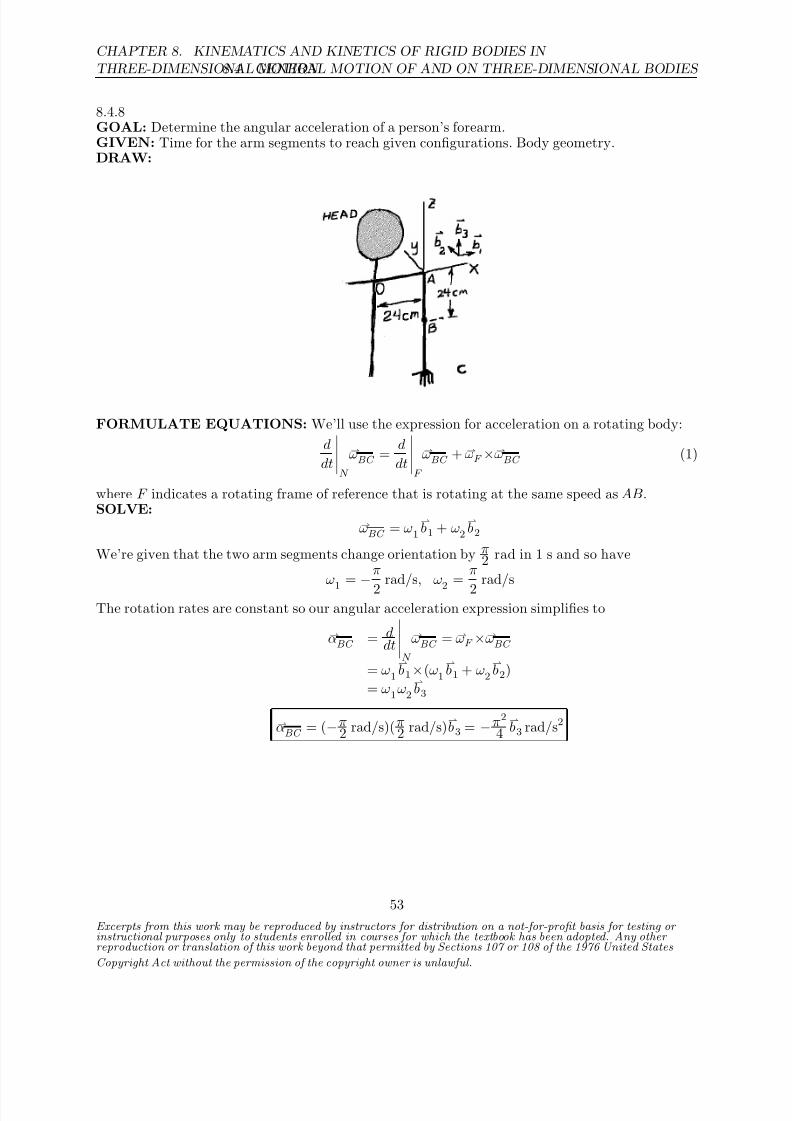
8.4.8GOAL: Determine the angular acceleration of a person’s forearm.GIVEN: Time for the arm segments to reach given configurations. Body geometry.DRAW:
FORMULATE EQUATIONS: We’ll use the expression for acceleration on a rotating body:
d
dt
N
ωBC = d
dt
F
ωBC + ωF ×ωBC (1)
where F indicates a rotating frame of reference that is rotating at the same speed as AB.SOLVE:
ωBC = ω1
b1 + ω2
b2
We’re given that the two arm segments change orientation by π2 rad in 1 s and so have
ω1
=−
π
2 rad/s, ω
2
= π
2 rad/s
The rotation rates are constant so our angular acceleration expression simplifies to
αBC = ddt
N
ωBC = ωF ×ωBC
= ω1
b1×(ω1
b1 + ω2
b2)
= ω1ω2
b3
αBC
= (−π2 rad/s)( π
2 rad/s)b3 = −π2
4b3 rad/s2
Excerpts from this work may be reproduced by instructors for distribution on a not-for-profit basis for testing or instructional purposes only to students enrolled in courses for which the textbook has been adopted. Any other reproduction or translation of this work beyond that permitted by Sections 107 or 108 of the 1976 United States
Copyright Act without the permission of the copyright owner is unlawful.
53

8/21/2019 Kinematics and kinetics of rigidbodies
http://slidepdf.com/reader/full/kinematics-and-kinetics-of-rigidbodies 20/190
8.4. GENERAL MOTION OF AND ON THREE-DIMENSIONAL BODIES
CHAPTER 8. KINEMATICS AND KINETICS OF RIGID BODIES IN
THREE-DIMENSIONAL MOTION
8.4.9GOAL: Determine a forearm’s angular acceleration for 0 ≤ t ≤ 1 s.GIVEN: Rotational information with regard to the arm segments and body geometry.DRAW:
FORMULATE EQUATIONS: We’ll use the expression for acceleration on a rotating body:
d
dt
N
ωBC = d
dt
F
ωBC + ωF ×ωBC (1)
where F indicates a rotating frame of reference that is rotating at the same speed as AB.SOLVE: The arm segment AB alters orientation by π
2 rad in 1 s and so we have
ωAB
= ω1
b1 = −π
2
b1 rad/s
BC rotates with a constant angular acceleration relative to AB such that after starting from restit has moved π
2 rad after 1 s. Denoting its relative rotation angle with φ, we have
∆φ = π
2 rad =
1
2φt2 ⇒ φ =
2(π/2)
(1s)2 ⇒ φ = π rad/s2
We can now use our formula for the derivative of a vector in a rotating body:
αBC = ddt
F
ωBC + ωF ×ωBC
= φb2 + ω1
b1×(ω1
b1 + (φt)
b2)
= φb2 + ω1 φt
b3
αBC = πb2 rad/s2 −
π2
2b3 rad/ s3
t
Excerpts from this work may be reproduced by instructors for distribution on a not-for-profit basis for testing or instructional purposes only to students enrolled in courses for which the textbook has been adopted. Any other reproduction or translation of this work beyond that permitted by Sections 107 or 108 of the 1976 United States
Copyright Act without the permission of the copyright owner is unlawful.
54

8/21/2019 Kinematics and kinetics of rigidbodies
http://slidepdf.com/reader/full/kinematics-and-kinetics-of-rigidbodies 21/190
CHAPTER 8. KINEMATICS AND KINETICS OF RIGID BODIES IN
THREE-DIMENSIONAL MOTION 8.4. GENERAL MOTION OF AND ON THREE-DIMENSIONAL BODIES
8.4.10GOAL: Determine the angular velocity and angular acceleration of the forearm segment during agiven motion of the arm.GIVEN: Position of the forearm and upper arm at times t = 0 and t = 1 s, and the fact that theangular speeds of the segments are constant.
DRAW: The figures show the arm at times t = 0 and t = 1 s. The unit vectors
b1,
b2,
b3, fixed tothe upper arm, are shown along with the inertial x, y,z axes. At time t = 1 s, φ = 90 and ψ = 45.
FORMULATE EQUATIONS: We’ll use the formulas for the angular velocity and accelerationof a rotating body.SOLVE: Since the angular speeds are constant, we can determine the values by dividing the changein angle by the change in time:
ψ = ∆ψ∆t = π/4 rad1 s = π4 rad/s
φ = ∆φ
∆t =
π/2 rad
1 s =
π
2 rad/s
The angular velocity of the forearm is the angular velocity of the upper arm plus the angularvelocity of the forearm with respect to the upper arm:
ωBC
= ωAB
+ ωBC /AB
= −φb1 + ψ
b3
ωBC = −π2
b1 + π
4
b3 rad/s
The angular acceleration is thus:
αBC = ωBC = d
dt
−π
2
b1 +
π
4
b3
= −π
2
b 1 +
π
4
b 3 = 0 +
π
4
π
2
b2
αBC = π2
8
b2 rad/s2
Excerpts from this work may be reproduced by instructors for distribution on a not-for-profit basis for testing or instructional purposes only to students enrolled in courses for which the textbook has been adopted. Any other reproduction or translation of this work beyond that permitted by Sections 107 or 108 of the 1976 United States
Copyright Act without the permission of the copyright owner is unlawful.
55

8/21/2019 Kinematics and kinetics of rigidbodies
http://slidepdf.com/reader/full/kinematics-and-kinetics-of-rigidbodies 22/190
8.4. GENERAL MOTION OF AND ON THREE-DIMENSIONAL BODIES
CHAPTER 8. KINEMATICS AND KINETICS OF RIGID BODIES IN
THREE-DIMENSIONAL MOTION
Alternatively,
αBC = d
dt
AB
ωBC + ωAB
×ωBC
= d
dt
AB
−π
2
b1 +
π
4
b3
=0
+
−π
2
b1×
−π
2
b1 +
π
4
b3
= π2
8
b2 rad/s2
Excerpts from this work may be reproduced by instructors for distribution on a not-for-profit basis for testing or instructional purposes only to students enrolled in courses for which the textbook has been adopted. Any other reproduction or translation of this work beyond that permitted by Sections 107 or 108 of the 1976 United States
Copyright Act without the permission of the copyright owner is unlawful.
56

8/21/2019 Kinematics and kinetics of rigidbodies
http://slidepdf.com/reader/full/kinematics-and-kinetics-of-rigidbodies 23/190
CHAPTER 8. KINEMATICS AND KINETICS OF RIGID BODIES IN
THREE-DIMENSIONAL MOTION 8.4. GENERAL MOTION OF AND ON THREE-DIMENSIONAL BODIES
8.4.11GOAL: Find the angular velocity of gear G2.
GIVEN: vA = 10k m/s, vB = −10
k m/s. r1 = 0.2 m, r2 = 0.3 m, d = 0.5 m.
DRAW:
FORMULATE EQUATIONS: We’ll use the equations for finding velocities on rotating bodies.
SOLVE: All bodies in the differential have two rotational degrees of freedom, which are in the
ıand directions. No rotation is allowed in the k direction, as both wheels remain in contact with
the ground. Let
ωA = ωA1ı + ωA2
ωB = ωB1
ı + ωB2
ωC = ωC 1ı + ωC 2
ωG3
= ωG31ı + ωG32
ωG4
= ωG41ı + ωG42
By the geometric constraints, ωA2 = ωB2 = ωC 2, and ωG31 = ωG41 = ωC 1.We begin by computing the angular velocities of wheels A and B from the given linear velocitiesand the rolling constraint. vA, vB refer to the velocity of the centerpoints of the two wheels,respectively, and ωA, ωB refer to the angular velocity of the wheels themselves. The wheels havetwo angular velocity components, one in the ı direction and another in the direction (due to thelefthand turn).
vA = ωA×rA/G
vB = ωB ×rB /H
vAk = (ωA1
ı + ωA2 )×r2
vBk = (ωB1
ı + ωB2 )×r2
⇒ ωA1 = vA/r2 ⇒ ωB1 = vB/r2
The above yields:
ωA1 = 10 m/s0.3 m
= 33.3 rad/s
ωB1 = −10 m/s
0.3 m = −33.3 rad/s
To determine the components of the wheel angular velocities we’ll use the relative motion of B
Excerpts from this work may be reproduced by instructors for distribution on a not-for-profit basis for testing or instructional purposes only to students enrolled in courses for which the textbook has been adopted. Any other reproduction or translation of this work beyond that permitted by Sections 107 or 108 of the 1976 United States
Copyright Act without the permission of the copyright owner is unlawful.
57

8/21/2019 Kinematics and kinetics of rigidbodies
http://slidepdf.com/reader/full/kinematics-and-kinetics-of-rigidbodies 24/190
8.4. GENERAL MOTION OF AND ON THREE-DIMENSIONAL BODIES
CHAPTER 8. KINEMATICS AND KINETICS OF RIGID BODIES IN
THREE-DIMENSIONAL MOTION
with respect to A (in this case point A can be considered an extended point of wheel B ):
vB = vA + ωB ×rB /A
vBk = vA
k + (ωB1
ı + ωB2 )×2dı
⇒ ωB2 =
−vB + vA
2d
= 10 m/s + 10 m/s
2(0.5 m)
= 20.0 rad/s
Having both ωB1
and ωB2
, and knowing that wheel B is rigidly attached to gear G2, we have
ωG2 = ω1
ı + ω2 = (−33.3ı + 20.0 ) rad/s
Excerpts from this work may be reproduced by instructors for distribution on a not-for-profit basis for testing or instructional purposes only to students enrolled in courses for which the textbook has been adopted. Any other reproduction or translation of this work beyond that permitted by Sections 107 or 108 of the 1976 United States
Copyright Act without the permission of the copyright owner is unlawful.
58

8/21/2019 Kinematics and kinetics of rigidbodies
http://slidepdf.com/reader/full/kinematics-and-kinetics-of-rigidbodies 25/190
CHAPTER 8. KINEMATICS AND KINETICS OF RIGID BODIES IN
THREE-DIMENSIONAL MOTION 8.4. GENERAL MOTION OF AND ON THREE-DIMENSIONAL BODIES
8.4.12GOAL: Determine the highest velocity point on a rolling ice cream cone.GIVEN: Cone dimensions. Time to make a full circle on the floor is 2 s.DRAW:
FORMULATE EQUATIONS: We’ll use the equations for finding velocities on rotating bodies.SOLVE: Example 8.4 shows how to determine the angular velocities of a rotating disk on theend of a bent shaft. The current homework problem can be thought of as precisely the sameproblem. The motion of OA will be the same as that of Example 8.4’s shaft. From observation
we can deduce that the maximal speed will be found at the point B, the topmost point of thecone at the pictured instant. From geometry we have β = sin−1(0.25) = 14.48. |AB| = 1in and|OA| =
√ 42 − 12 in = 3.873in
The cone takes 2 s to complete one full rotation around the floor and thus we have
ωOA
= 2π
2 s = π rad/s
The correspondence between our problem and that of Example 8.4 isωcone → ω
W ωAO
→ ωS
3.873in → L11 in → L2
Substituting these values into the expression for ωW gives us
ωcone = (π rad/s)
sin β − 3.873cos β + sin β
1
c1 + (π rad/s) cos β c3
= (−11.78c1 + 3.042c3) rad/s
vB = ωcone ×rB /O
= (−11.78c1 + 3.042c3) rad/s×(3.873c1 + c3) in
vB = 23.56c2 in/ s
Excerpts from this work may be reproduced by instructors for distribution on a not-for-profit basis for testing or instructional purposes only to students enrolled in courses for which the textbook has been adopted. Any other reproduction or translation of this work beyond that permitted by Sections 107 or 108 of the 1976 United States
Copyright Act without the permission of the copyright owner is unlawful.
59
8/21/2019 Kinematics and kinetics of rigidbodies
http://slidepdf.com/reader/full/kinematics-and-kinetics-of-rigidbodies 26/190
8.4. GENERAL MOTION OF AND ON THREE-DIMENSIONAL BODIES
CHAPTER 8. KINEMATICS AND KINETICS OF RIGID BODIES IN
THREE-DIMENSIONAL MOTION
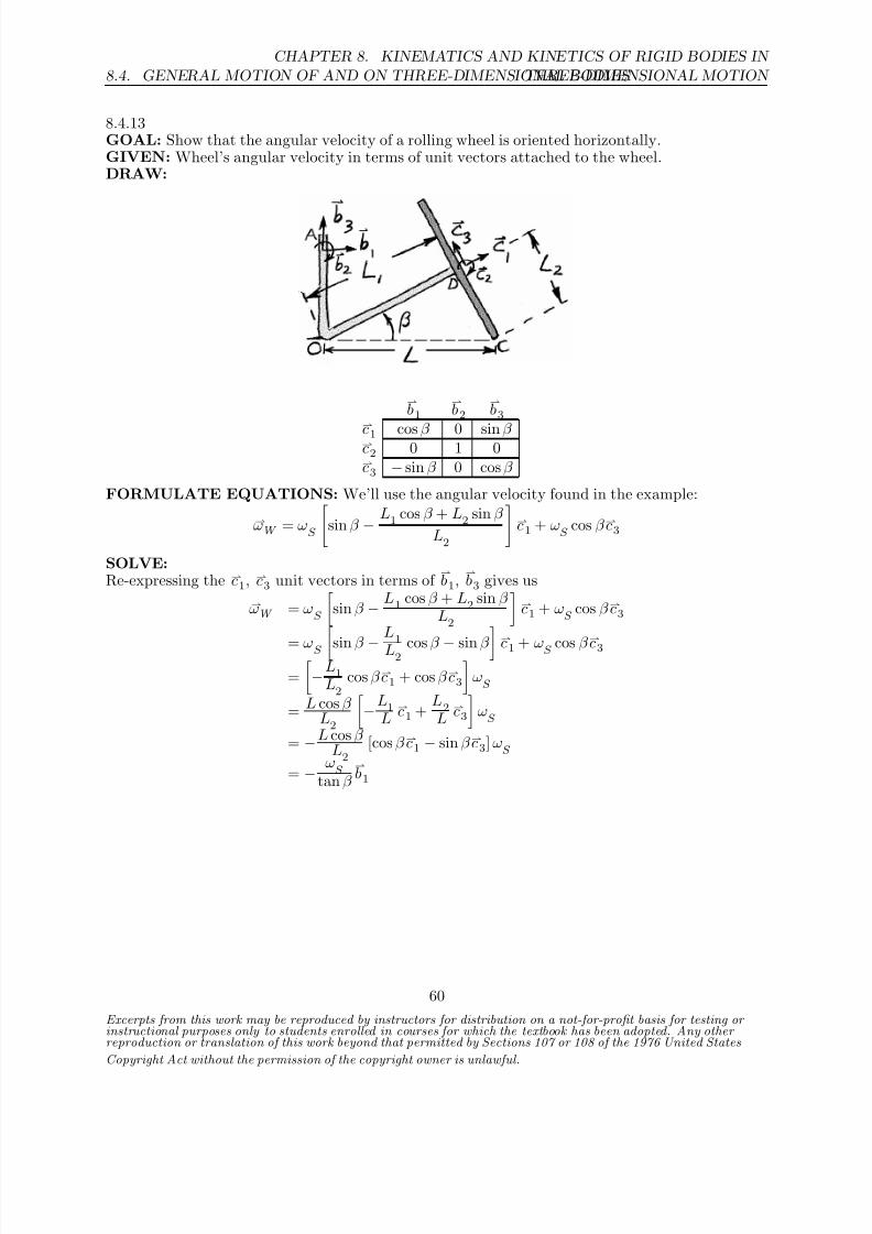
8.4.13GOAL: Show that the angular velocity of a rolling wheel is oriented horizontally.GIVEN: Wheel’s angular velocity in terms of unit vectors attached to the wheel.DRAW:
b1
b2
b3
c1 cos β 0 sin β c2 0 1 0c3 − sin β 0 cos β
FORMULATE EQUATIONS: We’ll use the angular velocity found in the example:
ωW = ωS
sin β − L1 cos β + L2 sin β
L2
c1 + ω
S cos β c3
SOLVE:Re-expressing the c1, c3 unit vectors in terms of
b1,
b3 gives us
ωW = ωS
sin β − L1 cos β + L2 sin β
L2
c1 + ω
S cos β c3
= ωS sin β − L1
L2 cos β − sin β
c1 + ωS cos β
c3
=
−L1
L2cos β c1 + cos β c3
ωS
= L cos β L2
−L1
Lc1 +
L2L
c3
ωS
= −L cos β L2
[cos β c1 − sin β c3] ωS
= − ωS
tan β b1
Excerpts from this work may be reproduced by instructors for distribution on a not-for-profit basis for testing or instructional purposes only to students enrolled in courses for which the textbook has been adopted. Any other reproduction or translation of this work beyond that permitted by Sections 107 or 108 of the 1976 United States
Copyright Act without the permission of the copyright owner is unlawful.
60
8/21/2019 Kinematics and kinetics of rigidbodies
http://slidepdf.com/reader/full/kinematics-and-kinetics-of-rigidbodies 27/190
CHAPTER 8. KINEMATICS AND KINETICS OF RIGID BODIES IN
THREE-DIMENSIONAL MOTION 8.4. GENERAL MOTION OF AND ON THREE-DIMENSIONAL BODIES
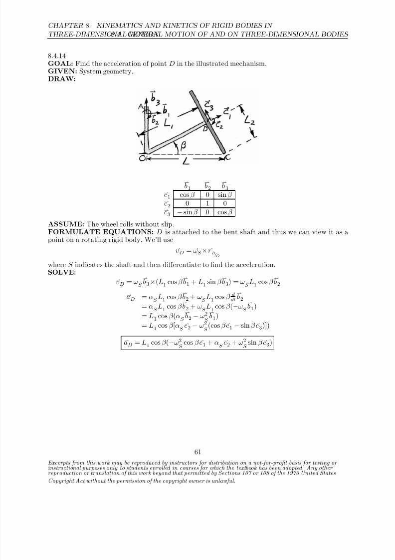
8.4.14GOAL: Find the acceleration of point D in the illustrated mechanism.GIVEN: System geometry.DRAW:
b1
b2
b3
c1 cos β 0 sin β c2 0 1 0c3 − sin β 0 cos β
ASSUME: The wheel rolls without slip.FORMULATE EQUATIONS: D is attached to the bent shaft and thus we can view it as apoint on a rotating rigid body. We’ll use
vD = ωS ×rD/O
where S indicates the shaft and then differentiate to find the acceleration.SOLVE:
vD = ωS
b3×(L1 cos β
b1 + L1 sin β
b3) = ω
S L1 cos β
b2
aD = αS L1 cos β b2 + ωS L1 cos β ddtb2
= αS
L1 cos β b2 + ω
S L1 cos β (−ω
S
b1)
= L1 cos β (αS
b2 − ω2
S
b1)
= L1 cos β [αS c2 − ω2
S (cos β c1 − sin β c3)])
aD = L1 cos β (−ω2S
cos β c1 + αS c2 + ω2
S sin β c3)
Excerpts from this work may be reproduced by instructors for distribution on a not-for-profit basis for testing or instructional purposes only to students enrolled in courses for which the textbook has been adopted. Any other reproduction or translation of this work beyond that permitted by Sections 107 or 108 of the 1976 United States
Copyright Act without the permission of the copyright owner is unlawful.
61

8/21/2019 Kinematics and kinetics of rigidbodies
http://slidepdf.com/reader/full/kinematics-and-kinetics-of-rigidbodies 28/190
8.4. GENERAL MOTION OF AND ON THREE-DIMENSIONAL BODIES
CHAPTER 8. KINEMATICS AND KINETICS OF RIGID BODIES IN
THREE-DIMENSIONAL MOTION
8.4.15GOAL: Explain what the physical root is for the angular acceleration components of the disk inExample 8.4.GIVEN: Angular velocity and acceleration of the disk.DRAW:
b1
b2
b3
c1 cos β 0 sin β c2 0 1 0c3 − sin β 0 cos β
FORMULATE EQUATIONS: The problem statement involves b1 and
b3. We’ll start with the
angular velocity found in the example and re-express it in terms of these unit vectors. Then we’lldifferentiate to find the angular acceleration.SOLVE:ωW is given by
ωW = ωS sin β − L1 cos β + L2 sin β
L2
c1 + ωS
cos β c3
Re-expressing the c1, c3 unit vectors in terms of b1,
b3 gives us
ωW = ωS
sin β − L1 cos β + L2 sin β
L2
c1 + ω
S cos β c3
= ωS
sin β − L1
L2cos β − sin β
c1 + ω
S cos β c3
=
−L1
L2cos β c1 + cos β c3
ωS
= L cos β L2
−L1
Lc1 +
L2L
c3
ωS
= −L cos β
L2 [cos β
c1 − sin β
c3] ωS
= − ωS
tan β b1
We can differentiate by viewing this as a vector in a rotating reference frame, the frame defined bythe bent shaft. Let S indicate a rotating frame of reference that rotates at the same rate as theshaft.
Excerpts from this work may be reproduced by instructors for distribution on a not-for-profit basis for testing or instructional purposes only to students enrolled in courses for which the textbook has been adopted. Any other reproduction or translation of this work beyond that permitted by Sections 107 or 108 of the 1976 United States
Copyright Act without the permission of the copyright owner is unlawful.
62

8/21/2019 Kinematics and kinetics of rigidbodies
http://slidepdf.com/reader/full/kinematics-and-kinetics-of-rigidbodies 29/190
CHAPTER 8. KINEMATICS AND KINETICS OF RIGID BODIES IN
THREE-DIMENSIONAL MOTION 8.4. GENERAL MOTION OF AND ON THREE-DIMENSIONAL BODIES
αW = d
dt
N
ωW = d
dt
S
ωW + ωS ×ωW
= d
dt
S
− ω
S tan β
b1
+ ω
S
b3×
− ω
S tan β
b1
= − α
S
tan β
b1 −ω2S
tan β
b2
Both terms depend upon the angular speed and acceleration of the shaft because the wheel’srotation is determined (through a rolling constraint) on the velocity of its center (which is drivenby one end of the rotating shaft).
The first term, − αS
tan β b1, arises when differentiating the angular velocity with respect to the rotat-
ing frame. Physically it corresponds to the “usual” way we’d expect to see an angular accelerationarise, namely by the shaft’s rotation rate increasing (or decreasing) so as to create a non-zeroacceleration. If the shaft were to rotate at a constant rate this term would disappear.
The second term,ω2S
tan β b2, comes about because the angular velocity (which points in the −
b1
direction) is swept around in a circle as the shaft rotates. The rotation is positive in the b3
direction (counter-clockwise when looking down at the system along the −b3 direction) and thisrotation causes the angular velocity vector to rotate as well, its tip moving in the −
b2 direction.
Excerpts from this work may be reproduced by instructors for distribution on a not-for-profit basis for testing or instructional purposes only to students enrolled in courses for which the textbook has been adopted. Any other reproduction or translation of this work beyond that permitted by Sections 107 or 108 of the 1976 United States
Copyright Act without the permission of the copyright owner is unlawful.
63

8/21/2019 Kinematics and kinetics of rigidbodies
http://slidepdf.com/reader/full/kinematics-and-kinetics-of-rigidbodies 30/190
8.4. GENERAL MOTION OF AND ON THREE-DIMENSIONAL BODIES
CHAPTER 8. KINEMATICS AND KINETICS OF RIGID BODIES IN
THREE-DIMENSIONAL MOTION
8.4.16GOAL: Find the acceleration of point C in the illustrated mechanism. L1 = 10cm, β = 15.ωshaft = 3
b3 rad/s.
GIVEN: System geometry.DRAW:
b1
b2
b3
c1 cos β 0 sin β c2 0 1 0c3 − sin β 0 cos β
ASSUME: The wheel rolls without slip.FORMULATE EQUATIONS: We’ll start with the angular velocity of the wheel, as found inthe example. After re-expressing this in terms of
b1,
b2,
b3 we’ll differentiate to find αW . Then, by
viewing the body as rotating about the fixed point O, we’ll determine the acceleration using ourrigid body acceleration formula
aC = αW
×rC /O
+ ωW
×ωW
×rC /O (1)
SOLVE:
ωW = ωS
sin β − L1 cos β + L2 sin β
L2
c1 + ω
S cos β c3
Re-expressing the c1, c3 unit vectors in terms of b1,
b3 gives us
ωW = ωS
sin β − L1 cos β + L2 sin β
L2
c1 + ω
S cos β c3
= ωS
sin β − L1
L2cos β − sin β
c1 + ω
S cos β c3
=
−L1
L2cos β c1 + cos β c3
ωS
= L cos β
L2−L
1L
c1 + L
2L
c3ωS
= −L cos β L2
[cos β c1 − sin β c3] ωS
= − ωS
tan β b1
Excerpts from this work may be reproduced by instructors for distribution on a not-for-profit basis for testing or instructional purposes only to students enrolled in courses for which the textbook has been adopted. Any other reproduction or translation of this work beyond that permitted by Sections 107 or 108 of the 1976 United States
Copyright Act without the permission of the copyright owner is unlawful.
64

8/21/2019 Kinematics and kinetics of rigidbodies
http://slidepdf.com/reader/full/kinematics-and-kinetics-of-rigidbodies 31/190
CHAPTER 8. KINEMATICS AND KINETICS OF RIGID BODIES IN
THREE-DIMENSIONAL MOTION 8.4. GENERAL MOTION OF AND ON THREE-DIMENSIONAL BODIES
αW = − αS
tan β
b1 − ω
S
tan β
d
dt
b1 = − 1
tan β
αS
b1 + ω2
S
b2
Using these expressions in (1) gives us
aC = − 1
tan β
αS
b1 + ω2
S
b2
×L
b1 − ω
S
tan β
b1×
− ω
S
tan β
b1×L
b1
Interestingly, the second term drops out (
b1×
b1 = 0), leaving us with
aC =Lω2
S
tan β
b3
From geometry we have
L = 10.35cm
aC = (0.1035 m)(3 rad/s)2
tan15b3 = 3.48
b3 m/s2
Excerpts from this work may be reproduced by instructors for distribution on a not-for-profit basis for testing or instructional purposes only to students enrolled in courses for which the textbook has been adopted. Any other reproduction or translation of this work beyond that permitted by Sections 107 or 108 of the 1976 United States
Copyright Act without the permission of the copyright owner is unlawful.
65
8/21/2019 Kinematics and kinetics of rigidbodies
http://slidepdf.com/reader/full/kinematics-and-kinetics-of-rigidbodies 32/190
8.4. GENERAL MOTION OF AND ON THREE-DIMENSIONAL BODIES
CHAPTER 8. KINEMATICS AND KINETICS OF RIGID BODIES IN
THREE-DIMENSIONAL MOTION
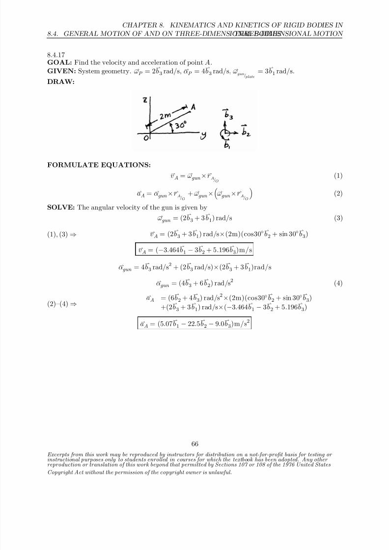
8.4.17GOAL: Find the velocity and acceleration of point A.GIVEN: System geometry. ωP = 2
b3 rad/s, αP = 4
b3 rad/s, ω
gun /plate= 3
b1 rad/s.
DRAW:
FORMULATE EQUATIONS:vA = ωgun ×rA/O
(1)
aA = αgun ×rA/O+ ωgun ×ωgun ×rA/O
(2)
SOLVE: The angular velocity of the gun is given byωgun = (2
b3 + 3
b1) rad/s (3)
(1), (3) ⇒ vA = (2b3 + 3
b1) rad/s×(2m)(cos30
b2 + sin 30
b3)
vA = (−3.464b1 − 3
b2 + 5.196
b3)m/s
αgun = 4b3 rad/s2 + (2
b3 rad/s)×(2
b3 + 3
b1)rad/s
αgun = (4b3 + 6
b2) rad/s2 (4)
(2)–(4) ⇒aA = (6
b2 + 4
b3) rad/s2×(2m)(cos30
b2 + sin 30
b3)
+(2b3 + 3
b1) rad/s×(−3.464
b1 − 3
b2 + 5.196
b3)
aA = (5.07b1 − 22.5
b2 − 9.0
b3)m/s2
Excerpts from this work may be reproduced by instructors for distribution on a not-for-profit basis for testing or instructional purposes only to students enrolled in courses for which the textbook has been adopted. Any other reproduction or translation of this work beyond that permitted by Sections 107 or 108 of the 1976 United States
Copyright Act without the permission of the copyright owner is unlawful.
66

8/21/2019 Kinematics and kinetics of rigidbodies
http://slidepdf.com/reader/full/kinematics-and-kinetics-of-rigidbodies 33/190
CHAPTER 8. KINEMATICS AND KINETICS OF RIGID BODIES IN
THREE-DIMENSIONAL MOTION 8.4. GENERAL MOTION OF AND ON THREE-DIMENSIONAL BODIES
8.4.18GOAL: Find the rate β at which the water cannon is pivoting up at a given instant ( β = 10).GIVEN: Base rotates about Z -axis at 4 rad/s, the magnitude of the tip B’s velocity is 6 m/s atthe instant when β = 10.DRAW: The figure below depicts the canon with the original X, Y,Z axes and a set of unit vectors
bi that are fixed to the rotating base.
ASSUME: We assume that the given rotation rate of the base is in the positive k direction. It
could just as easily be assumed that the rotation is in the negative k direction, without affecting
the magnitude of the tip’s velocity or the calculated value of β .FORMULATE EQUATIONS: We’ll use the equation for velocity on a rotating body.SOLVE: The rotation rate of the base is 4
k rad/s, and that of the barrel with respect to the base
is β b1. The total angular velocity of the barrel is thus:
ω = 4k + β
b1 = 4
b3 + β
b1
as k =
b3.
The velocity of the tip B is:
vB
= ω×rB /O
=
4b3 + β
b1
×
1.2cos10b2 + 1.2sin10
b3
= −4(1.2)cos10
b1 − 1.2 β sin10
b2 + 1.2 β cos10
b3 m/s
The magnitude of the velocity is (vB · v
B )1/2 and is given as 6 m/s:
vB
=
−4.8cos10 m/s
2+
1.2 β cos10 m/s2
+
1.2 β sin10 m/s2
6 m/s = −4.8cos10 m/s2
+ 1.2 β m/s2
β = 3.08 rad/s
Excerpts from this work may be reproduced by instructors for distribution on a not-for-profit basis for testing or instructional purposes only to students enrolled in courses for which the textbook has been adopted. Any other reproduction or translation of this work beyond that permitted by Sections 107 or 108 of the 1976 United States
Copyright Act without the permission of the copyright owner is unlawful.
67

8/21/2019 Kinematics and kinetics of rigidbodies
http://slidepdf.com/reader/full/kinematics-and-kinetics-of-rigidbodies 34/190
8.4. GENERAL MOTION OF AND ON THREE-DIMENSIONAL BODIES
CHAPTER 8. KINEMATICS AND KINETICS OF RIGID BODIES IN
THREE-DIMENSIONAL MOTION
8.4.19GOAL: Determine the total angular acceleration of a model airplane propeller using two meth-ods: a) differentiation of the components of the angular velocity vector, and b) the formula fordifferentiating a vector in a rotating frame:
d
dtN
p = d
dtS
p +
ω×
p
GIVEN: The airplane is attached to a tether and circles its attachment point O with a currentangular velocity of ω3 rad/s and an angular acceleration of α3 rad/s2. The propeller turns with
angular velocity ω2 rad/s and angular acceleration α2 rad/s2, both with respect to the model.
DRAW: The b1,
b2,
b3 frame is attached to the plane.
FORMULATE EQUATIONS: We’ll use the equation for angular velocity and angular acceler-ation of a rotating body.SOLVE: The angular velocity of the propeller is the sum of the angular velocity of the plane andthe angular velocity of the propeller with respect to the plane:
ω = ω3
b3 + ω2
b2
a) Differentiating:
α = ω = ω3
b3 + ω3
b 3 + ω2
b2 + ω2
b 2
= α3
b3 + ω3(0) + α2
b2 + ω2(−ω3
b1)
α = −ω2ω3
b1 + α2
b2 + α3
b3
b) Using formula for differentiation in the rotating frame B (with b i attached):
α = d
dt
N
ω = d
dt
B
ω + ωB
×ω
=
d
dt B ω3
b3 + ω2
b2 + ω3
b3×ω3
b3 + ω2
b2= α3
b3 + α2
b2 − ω2ω3
b1
α = −ω2ω3
b1 + α2
b2 + α3
b3
Excerpts from this work may be reproduced by instructors for distribution on a not-for-profit basis for testing or instructional purposes only to students enrolled in courses for which the textbook has been adopted. Any other reproduction or translation of this work beyond that permitted by Sections 107 or 108 of the 1976 United States
Copyright Act without the permission of the copyright owner is unlawful.
68

8/21/2019 Kinematics and kinetics of rigidbodies
http://slidepdf.com/reader/full/kinematics-and-kinetics-of-rigidbodies 35/190
CHAPTER 8. KINEMATICS AND KINETICS OF RIGID BODIES IN
THREE-DIMENSIONAL MOTION 8.4. GENERAL MOTION OF AND ON THREE-DIMENSIONAL BODIES
8.4.20GOAL: Find the velocity and acceleration of point B .GIVEN: System geometry. ωOA
≡ ω1 = 0.8b3 rad/s, αOA
≡ α1 = 2b3 rad/s2, ω
AB /torso≡ ω2 =
−1.6b1 rad/s, αAB /torso
≡ α2 = −0.5b1 rad/s2,
DRAW:
FORMULATE EQUATIONS: We’ll use the general rigid body equationsvB =
vA + ω
×rB /
A
(1)
aB = aA + α×rB /A
+ ω×ω×rB /A
(2)
SOLVE:
(1) ⇒ vA = (0.8b3)rad/s×(0.24
b1 m) = 0.192
b2 m/s (3)
(2) ⇒ aA = 2b3 rad/s2×(0.24
b1 m) + 0.8
b3 rad/s×(0.192
b2 m/s)
= (0.48b2 − 0.1536
b1)m/s2
(4)
(1), (3) ⇒ vB = 0.192b2 m/s + (0.8
b3 − 1.6
b1) rad/s×(−0.24
b3 m)
= (0.192 − 0.384)b2 m/s
vB = −0.192b2 m/s
αAB
= α1 + α2 + ω1×(ω1 + ω2)
= (2b3 − 0.5
b1)rad/s2 + (0.8
b3 rad/s)×(0.8
b3 rad/s − 1.6
b1 rad/s)
= (−0.5b1 − 1.28
b2 + 2.0
b3)rad/s2
Using (1),(2) and (4) gives usaB = aA + (−0.5
b1 − 1.28
b2 + 2.0
b3) rad/s2×(−0.24
b3 m)
+(0.8b3 − 1.6
b1)×
(0.8
b3 − 1.6
b1)×(−0.24
b3 m)
= (0.48
b2 − 0.1536
b1)m/s2
+(−0.12b2 + 0.3072
b1)m/s2
+(0.8
b3 − 1.6
b1)rad/s×(−0.384
b2 m/s)
aB = (0.461b1 + 0.36
b2 + 0.614
b3)m/s2
Excerpts from this work may be reproduced by instructors for distribution on a not-for-profit basis for testing or instructional purposes only to students enrolled in courses for which the textbook has been adopted. Any other reproduction or translation of this work beyond that permitted by Sections 107 or 108 of the 1976 United States
Copyright Act without the permission of the copyright owner is unlawful.
69
8/21/2019 Kinematics and kinetics of rigidbodies
http://slidepdf.com/reader/full/kinematics-and-kinetics-of-rigidbodies 36/190
8.4. GENERAL MOTION OF AND ON THREE-DIMENSIONAL BODIES
CHAPTER 8. KINEMATICS AND KINETICS OF RIGID BODIES IN
THREE-DIMENSIONAL MOTION
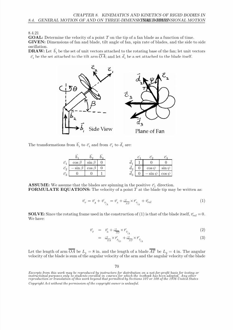
8.4.21GOAL: Determine the velocity of a point T on the tip of a fan blade as a function of time.GIVEN: Dimensions of fan and blade, tilt angle of fan, spin rate of blades, and the side to sideoscillation.DRAW: Let
bi be the set of unit vectors attached to the rotating base of the fan; let unit vectors
ci be the set attached to the tilt arm OA; and let
di be a set attached to the blade itself.
The transformations from bi to ci and from ci to
di are:
b1
b2
b3
c1c2
c3c1 cos β sin β 0
d1 1 0 0
c2 − sin β cos β 0
d2 0 cos ψ sin ψ
c3 0 0 1
d3 0 − sin ψ cos ψ
ASSUME: We assume that the blades are spinning in the positive c1 direction.FORMULATE EQUATIONS: The velocity of a point T at the blade tip may be written as:
vT
= vA
+ vT /A
= vA
+ ωAT
×rT /A
+ vrel (1)
SOLVE: Since the rotating frame used in the construction of (1) is that of the blade itself, vrel = 0.We have:
vT =
vA +
ωAT ×
rT /A (2)= ω
OA×r
A/O
+ ωAT
×rT /A
(3)
Let the length of arm OA be L1 = 8 in. and the length of a blade AT be L2 = 4 in. The angularvelocity of the blade is sum of the angular velocity of the arm and the angular velocity of the blade
Excerpts from this work may be reproduced by instructors for distribution on a not-for-profit basis for testing or instructional purposes only to students enrolled in courses for which the textbook has been adopted. Any other reproduction or translation of this work beyond that permitted by Sections 107 or 108 of the 1976 United States
Copyright Act without the permission of the copyright owner is unlawful.
70

8/21/2019 Kinematics and kinetics of rigidbodies
http://slidepdf.com/reader/full/kinematics-and-kinetics-of-rigidbodies 37/190
CHAPTER 8. KINEMATICS AND KINETICS OF RIGID BODIES IN
THREE-DIMENSIONAL MOTION 8.4. GENERAL MOTION OF AND ON THREE-DIMENSIONAL BODIES
with respect to the arm. From (3):
vT
= θb2×L1
c1 +
θb2 + ψc1
×L2
d2
= θ (sin β c1 + cos β c2)×L1c1 +
+ θ (sin β c1 + cos β c2) + ψc1×L2 (cos ψc2 + sin ψc3)
= −θL1 cos β c3 +
θ sin β + ψ
L2
cos ψ c3 − sin ψ c2
+ θL2 cos β sin ψ c1
Given θ = θ0 sin (ωt), taking the time derivative yields θ = θ0ω cos(ωt). Letting ψ0 = 0 such that
ψ = ψt = 26t gives:
vT
= 4 θ0ω cos(ωt)cos β sin(26t) c1 −
4 θ0ω cos(ωt)sin β + 104
sin(26t) c2+
+
4 θ0ω cos(ωt)sin β + 104
cos (26t) − 8 θ0ω cos(ωt)cos β c3 in/s
Excerpts from this work may be reproduced by instructors for distribution on a not-for-profit basis for testing or instructional purposes only to students enrolled in courses for which the textbook has been adopted. Any other reproduction or translation of this work beyond that permitted by Sections 107 or 108 of the 1976 United States
Copyright Act without the permission of the copyright owner is unlawful.
71

8/21/2019 Kinematics and kinetics of rigidbodies
http://slidepdf.com/reader/full/kinematics-and-kinetics-of-rigidbodies 38/190
8.4. GENERAL MOTION OF AND ON THREE-DIMENSIONAL BODIES
CHAPTER 8. KINEMATICS AND KINETICS OF RIGID BODIES IN
THREE-DIMENSIONAL MOTION
8.4.22GOAL: Find the acceleration of collar D .GIVEN: Angular velocity of link OB, angular velocity of link BC with respect to OB, and velocityat which collar D slides along link B C .DRAW:
Unit vectors bi are fixed to link OB, while unit vectors ci are fixed to link B C . At the illustrated
instant, both sets of unit vectors and the X,Y, Z axes are aligned.FORMULATE EQUATIONS: We’ll use the equation for motion on a three-dimensional body:
aD
= aB
+ α×rD/B
+ ω×ω×r
D/B
+ arel + 2ω×vrel (1)
SOLVE: The vectors quantities appearing in Equation (1) are:
aB
= ωOB
×ωOB
×rB /O
= θ
b1×
θb1×−0.5
b3
= 0.5 θ2
b3
ω = ωBC
= θb1 + φ
b3
α =
ωBC = ¨θ
b1 + ˙θ
db1
dt + ¨φ
b3 + ˙φ
db3
dt = 0 + 0 + 0 − ˙φ
˙θ
b2 = −˙
φ˙θ
b2vrel = 5 c2 m/sarel = 0rD/B
= 0.2 c2 m
The individual terms in (1), with θ = 4 rad/s and φ = 5 rad/s, are now:
Excerpts from this work may be reproduced by instructors for distribution on a not-for-profit basis for testing or instructional purposes only to students enrolled in courses for which the textbook has been adopted. Any other reproduction or translation of this work beyond that permitted by Sections 107 or 108 of the 1976 United States
Copyright Act without the permission of the copyright owner is unlawful.
72
8/21/2019 Kinematics and kinetics of rigidbodies
http://slidepdf.com/reader/full/kinematics-and-kinetics-of-rigidbodies 39/190
CHAPTER 8. KINEMATICS AND KINETICS OF RIGID BODIES IN
THREE-DIMENSIONAL MOTION 8.4. GENERAL MOTION OF AND ON THREE-DIMENSIONAL BODIES
aB
= (0.5 m) (4 rad/s)2 b3 = 8
b3 m/s2
α×rD/B
= −φθb2×0.2 c2 = 0
ω×
ω×
rD/B
= θ
b1 + φ
b3×θ
b1 + φ
b3×0.2
c2 = −0.2θ2 + φ2
b2
= − (0.2 m)
(4 rad/s)2 + (5 rad/s)2b2 = −8.2
b2 m/s2
2ω×vrel = 2
θb1 + φ
b3
×5 c2 = 10θ
b3 − 10 φ
b1
= (10 m/s) (4 rad/s) b3 − (10 m/s) (5 rad/s)
b1 =
40
b3 − 50
b1
m/s2
Substituting into (1):
aD
= 8 b3 + 0 − 8.2
b2 + 0 + 40
b3 − 50
b1 m/s2
aD = −50
b1 − 8.2
b2 + 48
b3 m/s2
Excerpts from this work may be reproduced by instructors for distribution on a not-for-profit basis for testing or instructional purposes only to students enrolled in courses for which the textbook has been adopted. Any other reproduction or translation of this work beyond that permitted by Sections 107 or 108 of the 1976 United States
Copyright Act without the permission of the copyright owner is unlawful.
73

8/21/2019 Kinematics and kinetics of rigidbodies
http://slidepdf.com/reader/full/kinematics-and-kinetics-of-rigidbodies 40/190
8.4. GENERAL MOTION OF AND ON THREE-DIMENSIONAL BODIES
CHAPTER 8. KINEMATICS AND KINETICS OF RIGID BODIES IN
THREE-DIMENSIONAL MOTION
8.4.23GOAL: Find the angular velocity of the central box C in a differential.GIVEN: vA = −2
k m/s, vB = −3
k m/s. r1 = 0.2 m, r2 = 0.3 m, d = 0.5 m.
DRAW:
FORMULATE EQUATIONS: We’ll use the equations for finding velocities on rotating bodies.
SOLVE: All bodies in the differential have two rotational degrees of freedom, which are in the
ıand directions. No rotation is allowed in the k direction, as both wheels remain in contact with
the ground. Let
ωA = ωA1ı + ωA2
ωB = ωB1
ı + ωB2
ωC = ωC 1ı + ωC 2
ωG3
= ωG31ı + ωG32
ωG4
= ωG41ı + ωG42
By the geometric constraints, ωA2 = ωB2 = ωC 2, and ωG31 = ωG41 = ωC 1.We begin by computing the angular velocities of wheels A and B from the given linear velocitiesand the rolling constraint. vA, vB refer to the velocity of the centerpoints of the two wheels,respectively, and ωA, ωB refer to the angular velocity of the wheels themselves. The wheels havetwo angular velocity components, one in the ı direction and another in the direction (due to thelefthand turn).
vA = ωA×rA/G
vB = ωB ×rB /H
vAk = (ωA1
ı + ωA2 )×r2
vBk = (ωB1
ı + ωB2 )×r2
⇒ ωA1 = vA/r2 ⇒ ωB1 = vB/r2
The above yields:
ωA1 = −2 m/s0.3 m
= −6.6 rad/s
ωB1 = −3 m/s
0.3 m = −10 rad/s
To determine the components of the wheel angular velocities we’ll use the relative motion of B
Excerpts from this work may be reproduced by instructors for distribution on a not-for-profit basis for testing or instructional purposes only to students enrolled in courses for which the textbook has been adopted. Any other reproduction or translation of this work beyond that permitted by Sections 107 or 108 of the 1976 United States
Copyright Act without the permission of the copyright owner is unlawful.
74

8/21/2019 Kinematics and kinetics of rigidbodies
http://slidepdf.com/reader/full/kinematics-and-kinetics-of-rigidbodies 41/190
CHAPTER 8. KINEMATICS AND KINETICS OF RIGID BODIES IN
THREE-DIMENSIONAL MOTION 8.4. GENERAL MOTION OF AND ON THREE-DIMENSIONAL BODIES
with respect to A (in this case point A can be considered an extended point of wheel B ):vB = vA + ωB ×r
B /A
vBk = vA
k + (ωB1
ı + ωB2 )×2dı
⇒ ωB2 = −vB + vA
2d =
3 m/s − 2 m/s
2(0.5 m) = 1.0 rad/s
Thus we haveωC 2 = ωB2 = ωA2 = 1.0 rad/s (1)
To find ωC 1 we need to determine the rate at which gears G3 and G4 are rotating about axle AB .Gears G3 and G4 roll against gears G1 and G2, and it is this rolling, in addition to the rolling of the wheels, that determines the ı component of ωC . Examining the relative velocities of the gearswith respect to each other and with respect to point O will allow us to find ωC 1 .
vF /O= ωC ×rF /O
= (ωC 1ı + ωC 2
)×r1
= ωC 1r1k
vF /O = ωC 1r1
k (2)Taking a different path to F from O:
vF /O= vE /O
+ vF /E
= [(ωA1ı + ωA2
)×(−r1ı + r1
)] + [(ωG31ı + ωG32
)×r1ı ]
= (ωA1r1 + ωA2r1 − ωG32r1)k
vF /O= (ωA1r1 + ωA2r1 − ωG32r1)
k (3)
Combining (2) and (3), we see that
ωC 1 = ωA1 + ωA2 − ωG32 (4)
Taking yet a different path:vF /O
= vJ /O+ vF /J
= [(ωB1ı + ωB2
)×(r1ı + r1
)] + [(ωG31ı + ωG32
)×−r1ı ]
= (ωB1r1 − ωB2r1 + ωG32r1)k
vF /O
= (ωB1r1 − ωB2r1 + ωG32r1)k (5)
Combining (2) and (5), we see that
ωC 1 = ωB1 − ωB2 + ωG32 (6)
Combining (4) and (6), with ωA2 = ωB2, yields:
ωC 1 = ωA1 + ωB1
2
(7)
Thus,
ωC = ωC 1ı + ωC 2
= −6.6 rad/s − 10 rad/s
2ı + 1.0 rad/s
ωC = −8.33ı + 1.0 rad/s
Excerpts from this work may be reproduced by instructors for distribution on a not-for-profit basis for testing or instructional purposes only to students enrolled in courses for which the textbook has been adopted. Any other reproduction or translation of this work beyond that permitted by Sections 107 or 108 of the 1976 United States
Copyright Act without the permission of the copyright owner is unlawful.
75

8/21/2019 Kinematics and kinetics of rigidbodies
http://slidepdf.com/reader/full/kinematics-and-kinetics-of-rigidbodies 42/190
8.4. GENERAL MOTION OF AND ON THREE-DIMENSIONAL BODIES
CHAPTER 8. KINEMATICS AND KINETICS OF RIGID BODIES IN
THREE-DIMENSIONAL MOTION
8.4.24GOAL: Find the angular velocity of Gear G3.GIVEN: vA = 10
k m/s, vB = 10
k m/s. r1 = 0.2 m, r2 = 0.3 m, d = 0.5 m.
DRAW:
FORMULATE EQUATIONS: We’ll use the equations for finding velocities on rotating bodies.
SOLVE: All bodies in the differential have two rotational degrees of freedom, which are in the
ıand directions. No rotation is allowed in the k direction, as both wheels remain in contact with
the ground. Let
ωA = ωA1ı + ωA2
ωB = ωB1
ı + ωB2
ωC = ωC 1ı + ωC 2
ωG3
= ωG31ı + ωG32
ωG4
= ωG41ı + ωG42
By the geometric constraints, ωA2 = ωB2 = ωC 2, and ωG31 = ωG41 = ωC 1.We begin by computing the angular velocities of wheels A and B from the given linear velocitiesand the rolling constraint. vA, vB refer to the velocity of the centerpoints of the two wheels,respectively, and ωA, ωB refer to the angular velocity of the wheels themselves. The wheels havetwo angular velocity components, one in the ı direction and another in the direction (due to thelefthand turn).
vA = ωA×rA/G
vB = ωB ×rB /H
vAk = (ωA1
ı + ωA2 )×r2
vBk = (ωB1
ı + ωB2 )×r2
⇒ ωA1 = vA/r2 ⇒ ωB1 = vB/r2
The above yields:
ωA1 = 10 m/s0.3 m
= 33.3 rad/s
ωB1 = 10 m/s
0.3 m = 33.3 rad/s
To determine the components of the wheel angular velocities we’ll use the relative motion of B
Excerpts from this work may be reproduced by instructors for distribution on a not-for-profit basis for testing or instructional purposes only to students enrolled in courses for which the textbook has been adopted. Any other reproduction or translation of this work beyond that permitted by Sections 107 or 108 of the 1976 United States
Copyright Act without the permission of the copyright owner is unlawful.
76

8/21/2019 Kinematics and kinetics of rigidbodies
http://slidepdf.com/reader/full/kinematics-and-kinetics-of-rigidbodies 43/190
CHAPTER 8. KINEMATICS AND KINETICS OF RIGID BODIES IN
THREE-DIMENSIONAL MOTION 8.4. GENERAL MOTION OF AND ON THREE-DIMENSIONAL BODIES
with respect to A (in this case point A can be considered an extended point of wheel B ):
vB = vA + ωB ×rB /A
vBk = vA
k + (ωB1
ı + ωB2 )×2dı
⇒ ωB2 =
−vB + vA
2d
= 10 m/s − 10 m/s
2(0.5 m)
= 0
Thus we haveωC 2 = ωB2 = ωA2 = 0 (1)
From the figure it is clear that gear G3 will have the same angular velocity as the carrier C as wellas an angular velocity with respect to C . Gears G3 and G4 roll against gears G1 and G2, and itis this rolling, in addition to the rolling of the wheels, that determines the ı component of ωC .Examining the relative velocities of the gears with respect to each other and with respect to pointO will allow us to find ωC 1.
vF /O
= ωC ×rF /O
= (ωC 1ı + ωC 2
)×r1
= ωC 1r1
k
vF /O= ωC 1r1
k (2)
Taking a different path to F from O:
vF /O= vE /O
+ vF /E
= [(ωA1ı + ωA2
)×(−r1ı + r1
)] + [(ωG31ı + ωG32
)×r1ı ]
= (ωA1r1 + ωA2r1 − ωG32r1)k
vF /O= (ωA1r1 + ωA2r1 − ωG32r1)
k (3)
Combining (2) and (3), we see thatωC 1 = ωA1 + ωA2 − ωG32 (4)
Taking yet a different path:
vF /O
= vJ /O
+ vF /J
= [(ωB1ı + ωB2
)×(r1ı + r1
)] + [(ωG31ı + ωG32
)×−r1ı ]
= (ωB1r1 − ωB2r1 + ωG32r1)k
vF /O= (ωB1r1 − ωB2r1 + ωG32r1)
k (5)
Combining (2) and (5), we see that
ωC 1 = ωB1 − ωB2 + ωG32 (6)
Combining (4) and (6), with ωA2 = ωB2, yields:
ωC 1 = ωA1 + ωB1
2 =
33.3 + 33.3
2 rad/s = 33.3 rad/s (7)
Excerpts from this work may be reproduced by instructors for distribution on a not-for-profit basis for testing or instructional purposes only to students enrolled in courses for which the textbook has been adopted. Any other reproduction or translation of this work beyond that permitted by Sections 107 or 108 of the 1976 United States
Copyright Act without the permission of the copyright owner is unlawful.
77

8/21/2019 Kinematics and kinetics of rigidbodies
http://slidepdf.com/reader/full/kinematics-and-kinetics-of-rigidbodies 44/190
8.4. GENERAL MOTION OF AND ON THREE-DIMENSIONAL BODIES
CHAPTER 8. KINEMATICS AND KINETICS OF RIGID BODIES IN
THREE-DIMENSIONAL MOTION
Thus,ωC = ωC 1
ı + ωC 2 = 33.3ı rad/s
We now haveωA = 33.3ı rad/s (8)
ωB = 33.3ı rad/s (9)
ωG3 = 33.3ı rad/s + φ (10)
where φ is the rotational speed of Gear G3 with respect to the carrier C .We can now apply the formula relating the velocity of two points on a rigid body, the body inquestion being gear G3.
vE = ωA×rE /G
= 33.3ı rad/s×[(d − r1)ı + (r2 + r1) ]
= 33.3(r2 + r1)k rad/s
(11)
vJ = ωB ×rJ /H
= 33.3ı rad/s×
[−
(d−
r1)ı + (r2 + r1) ]
= 33.3(r2 + r1)k rad/s
(12)
We’ll now applyvJ = vE +
ωG 3 ×rJ /E
(13)
(11), (12), (13) ⇒33.3(r2 + r1)
k rad/s = 33.3(r2 + r1)
k rad/s + (33.3ı rad/s + φ )×(2r1
ı )
φ = 0 (14)
(10), (14)
⇒ ωG3
= 33.3ı rad/s
Excerpts from this work may be reproduced by instructors for distribution on a not-for-profit basis for testing or instructional purposes only to students enrolled in courses for which the textbook has been adopted. Any other reproduction or translation of this work beyond that permitted by Sections 107 or 108 of the 1976 United States
Copyright Act without the permission of the copyright owner is unlawful.
78

8/21/2019 Kinematics and kinetics of rigidbodies
http://slidepdf.com/reader/full/kinematics-and-kinetics-of-rigidbodies 45/190
CHAPTER 8. KINEMATICS AND KINETICS OF RIGID BODIES IN
THREE-DIMENSIONAL MOTION 8.4. GENERAL MOTION OF AND ON THREE-DIMENSIONAL BODIES
8.4.25GOAL: Find the angular velocity of Gear G4.GIVEN: vA = 0, vB = −6
k m/s. r1 = 0.2 m, r2 = 0.3 m, r3 = 0.3 m, d = 0.5 m.
DRAW:
FORMULATE EQUATIONS: We’ll use the equations for finding velocities on rotating bodies.
SOLVE: All bodies in the differential have two rotational degrees of freedom, which are in the
ıand directions. No rotation is allowed in the k direction, as both wheels remain in contact with
the ground. Let
ωA = ωA1ı + ωA2
ωB = ωB1
ı + ωB2
ωC = ωC 1ı + ωC 2
ωG3
= ωG31ı + ωG32
ωG4
= ωG41ı + ωG42
By the geometric constraints, ωA2 = ωB2 = ωC 2, and ωG31 = ωG41 = ωC 1.We begin by computing the angular velocities of wheels A and B from the given linear velocitiesand the rolling constraint. vA, vB refer to the velocity of the centerpoints of the two wheels,respectively, and ωA, ωB refer to the angular velocity of the wheels themselves. The wheels havetwo angular velocity components, one in the ı direction and another in the direction (due to thelefthand turn).
vA = ωA×rA/G
vB = ωB ×rB /H
vAk = (ωA1
ı + ωA2 )×r2
vBk = (ωB1
ı + ωB2 )×r2
⇒ ωA1 = vA/r2 ⇒ ωB1 = vB/r2
The above yields:
ωA1 = 0 m/s0.3 m
= 0
ωB1 = −6 m/s
0.3 m = −20 rad/s
To determine the components of the wheel angular velocities we’ll use the relative motion of B
Excerpts from this work may be reproduced by instructors for distribution on a not-for-profit basis for testing or instructional purposes only to students enrolled in courses for which the textbook has been adopted. Any other reproduction or translation of this work beyond that permitted by Sections 107 or 108 of the 1976 United States
Copyright Act without the permission of the copyright owner is unlawful.
79

8/21/2019 Kinematics and kinetics of rigidbodies
http://slidepdf.com/reader/full/kinematics-and-kinetics-of-rigidbodies 46/190
8.4. GENERAL MOTION OF AND ON THREE-DIMENSIONAL BODIES
CHAPTER 8. KINEMATICS AND KINETICS OF RIGID BODIES IN
THREE-DIMENSIONAL MOTION
with respect to A (in this case point A can be considered an extended point of wheel B ):
vB = vA + ωB ×rB /A
vBk = vA
k + (ωB1
ı + ωB2 )×2dı
⇒ ωB2 =
−vB + vA
2d
= 6 m/s − 0
2(0.5 m)
= 6 r ad/s
Thus we haveωC 2 = ωB2 = ωA2 = 6 rad/s (1)
From the figure it is clear that gear G4 will have the same angular velocity as the carrier C as wellas an angular velocity with respect to C . Gears G3 and G4 roll against gears G1 and G2, and itis this rolling, in addition to the rolling of the wheels, that determines the ı component of ωC .Examining the relative velocities of the gears with respect to each other and with respect to pointO will allow us to find ωC 1.
vF /O= ωC ×rF /O
= (ωC 1ı + ωC 2
)×r1
= ωC 1r1
k
vF /O
= ωC 1r1k (2)
Taking a different path to F from O:
vF /O= vE /O
+ vF /E
= [(ωA1ı + ωA2
)×(−r1ı + r1
)] + [(ωG31ı + ωG32
)×r1ı ]
= (ωA1r1 + ωA2r1 − ωG32r1)k
vF /O
= (ωA1r1 + ωA2r1 − ωG32r1)k (3)
Combining (2) and (3), we see that
ωC 1 = ωA1 + ωA2 − ωG32 (4)
Taking yet a different path:
vF /O= vJ /O
+ vF /J
= [(ωB1ı + ωB2
)×(r1ı + r1
)] + [(ωG31ı + ωG32
)×−r1ı ]
= (ωB1r1 − ωB2r1 + ωG32r1)k
vF /O
= (ωB1r1 − ωB2r1 + ωG32r1)k (5)
Combining (2) and (5), we see that
ωC 1 = ωB1 − ωB2 + ωG32 (6)
Combining (4) and (6), with ωA2 = ωB2, yields:
ωC 1 = ωA1 + ωB1
2 =
0 − 20
2 rad/s = −10 rad/s
Excerpts from this work may be reproduced by instructors for distribution on a not-for-profit basis for testing or instructional purposes only to students enrolled in courses for which the textbook has been adopted. Any other reproduction or translation of this work beyond that permitted by Sections 107 or 108 of the 1976 United States
Copyright Act without the permission of the copyright owner is unlawful.
80

8/21/2019 Kinematics and kinetics of rigidbodies
http://slidepdf.com/reader/full/kinematics-and-kinetics-of-rigidbodies 47/190
CHAPTER 8. KINEMATICS AND KINETICS OF RIGID BODIES IN
THREE-DIMENSIONAL MOTION 8.4. GENERAL MOTION OF AND ON THREE-DIMENSIONAL BODIES
Thus,ωC = ωC 1
ı + ωC 2 = (−10ı + 6 ) rad/s
We now haveωA = 6 rad/s (7)
ωB = (−
20ı + 6 ) rad/s (8)
ωG4 = −10ı rad/s + (6 rad/s + φ) (9)
where φ is the rotational speed of Gear G4 with respect to the carrier C .We can now apply the formula relating the velocity of two points on a rigid body, the body inquestion being gear G4.
vK = ωA×rK /G
= 6 rad/s×[(d − r1)ı + (r2 − r1) ]
= −6(d − r1)k rad/s
(10)
vL = ωB ×rL/H
= (−
20ı + 6 ) rad/s×
[−
(d−
r1)ı + (r2−
r1) ]
= [−20(r2 − r1) + 6(d − r1)]k rad/s
(11)
We’ll now applyvL = vK +
ωG 4×rL/K
(12)
(10), (11), (12) ⇒
[−20(r2 − r1) + 6(d − r1)]k rad/s = −6(d − r1)
k rad/s + [−10 rad/sı + (6 rad/s + φ) ]×(2r1
ı )
−20(0.1 m/s) + 6(0.3m/s) = −6(0.3m/s) − (0.4 m)(6 rad/s + φ)
4 rad/s = −0.4 φ
φ = −10 rad/s (13)
(9), (13) ⇒ ωG4 = (−10ı − 4 ) rad/s
Excerpts from this work may be reproduced by instructors for distribution on a not-for-profit basis for testing or instructional purposes only to students enrolled in courses for which the textbook has been adopted. Any other reproduction or translation of this work beyond that permitted by Sections 107 or 108 of the 1976 United States
Copyright Act without the permission of the copyright owner is unlawful.
81

8/21/2019 Kinematics and kinetics of rigidbodies
http://slidepdf.com/reader/full/kinematics-and-kinetics-of-rigidbodies 48/190
8.5. MOMENTS AND PRODUCTS OF INERTIA FOR A THREE-DIMENSIONAL BODY
CHAPTER 8. KINEMATICS AND KINETICS OF RIGID BODIES IN
THREE-DIMENSIONAL MOTION
8.5 Moments and Products of Inertia for a Three-Dimensional
Body
Excerpts from this work may be reproduced by instructors for distribution on a not-for-profit basis for testing or instructional purposes only to students enrolled in courses for which the textbook has been adopted. Any other reproduction or translation of this work beyond that permitted by Sections 107 or 108 of the 1976 United States
Copyright Act without the permission of the copyright owner is unlawful.
82

8/21/2019 Kinematics and kinetics of rigidbodies
http://slidepdf.com/reader/full/kinematics-and-kinetics-of-rigidbodies 49/190
CHAPTER 8. KINEMATICS AND KINETICS OF RIGID BODIES IN
THREE-DIMENSIONAL MOTION 8.6. PARALLEL AXIS EXPRESSIONS FOR INERTIAS
8.6 Parallel Axis Expressions for Inertias
Excerpts from this work may be reproduced by instructors for distribution on a not-for-profit basis for testing or instructional purposes only to students enrolled in courses for which the textbook has been adopted. Any other reproduction or translation of this work beyond that permitted by Sections 107 or 108 of the 1976 United States
Copyright Act without the permission of the copyright owner is unlawful.
83

8/21/2019 Kinematics and kinetics of rigidbodies
http://slidepdf.com/reader/full/kinematics-and-kinetics-of-rigidbodies 50/190
8.6. PARALLEL AXIS EXPRESSIONS FOR INERTIAS
CHAPTER 8. KINEMATICS AND KINETICS OF RIGID BODIES IN
THREE-DIMENSIONAL MOTION
8.6.1GOAL: Determine the rotational inertias of the illustrated flat plate.GIVEN: Body’s orientation and dimensions.DRAW:
FORMULATE EQUATIONS: From Appendix B we have
I xx =
ma2
12 , I
yy = mb2
12 , I
zz = m(a2 + b2)
12
I xy = I
yz = I zx = 0
SOLVE:To find the mass moments of inertia and products of inertia we use (8.24)-(8.29) with r1 = b/2,r2 = a/2 and r3 = 0.
I xx = I xx + m(r2
2 + r2
3) =
ma2
3
I yy = I yy + m(r2
3 + r2
1) =
mb2
3
I zz = I zz
+ m(r21
+ r22
)
= ma2 + b2
12 + m b
22
+ a
22 =
m(a2 + b2)
3
I xy = I xy + mr1r2 = m
ab
4
I yz = I zx = 0
I xx = ma2
3 , I yy = mb2
3 , I xx = m(a2 + b2)
3 , I xy = mab4 , I yz = I zx = 0 ,
Excerpts from this work may be reproduced by instructors for distribution on a not-for-profit basis for testing or instructional purposes only to students enrolled in courses for which the textbook has been adopted. Any other reproduction or translation of this work beyond that permitted by Sections 107 or 108 of the 1976 United States
Copyright Act without the permission of the copyright owner is unlawful.
84

8/21/2019 Kinematics and kinetics of rigidbodies
http://slidepdf.com/reader/full/kinematics-and-kinetics-of-rigidbodies 51/190
CHAPTER 8. KINEMATICS AND KINETICS OF RIGID BODIES IN
THREE-DIMENSIONAL MOTION 8.6. PARALLEL AXIS EXPRESSIONS FOR INERTIAS
8.6.2GOAL: Determine the mass moments and products of inertia for the illustrated cylindrical body.GIVEN: Body’s orientation and dimensions.DRAW:
FORMULATE EQUATIONS: From Appendix B we have the rotational inertias about thebody’s mass center G:
I yy
= mr2
2 , I
xx =
m(3r2 + h2)
12
I xy
= I yz
= I zx
= 0
SOLVE:To find the mass moments of inertia and products of inertia we use (8.24)-(8.29) with r1 = 0,
r2 = h2 and r3 = r.
I yy = I yy + mr2 = 3mr2
2
I xx = I xx + m
r2 +
h2
2 = mh2
3 + 5mr2
4
From symmetry we see that I xy = 0 .The mass of the body is given by
m = ρπr2h
giving us
I xx = ρπr2h3
3 + 5ρπr4h
4 , I yy = 3ρπr4h
2
I xy = 0
Excerpts from this work may be reproduced by instructors for distribution on a not-for-profit basis for testing or instructional purposes only to students enrolled in courses for which the textbook has been adopted. Any other reproduction or translation of this work beyond that permitted by Sections 107 or 108 of the 1976 United States
Copyright Act without the permission of the copyright owner is unlawful.
85

8/21/2019 Kinematics and kinetics of rigidbodies
http://slidepdf.com/reader/full/kinematics-and-kinetics-of-rigidbodies 52/190
8.6. PARALLEL AXIS EXPRESSIONS FOR INERTIAS
CHAPTER 8. KINEMATICS AND KINETICS OF RIGID BODIES IN
THREE-DIMENSIONAL MOTION
8.6.3GOAL: Determine the illustrated body’s mass moments of inertia and products of inertia alongthe given x, y, z axes in terms of the body’s mass m.GIVEN: The body has an areal density of ρ and negligible thickness.DRAW:
FORMULATE EQUATIONS:The mass moments of inertia for a three-dimensional rigid body about axes parallel to its centroidalaxes are of the form
I xx = I xx + m
r2y + r2z
, etc. (1)
Likewise, a three-dimensional rigid body’s products of inertia about axes parallel to its centroidalaxes have the form
I xy = I xy + mrxry , etc. (2)
SOLVE:By breaking up the depicted body into a square plate and a square hole, we can analyze theinertia of each component separately and then combine our results to find the total system inertia.Analyzing the plate first, we have that its moments of inertia are given by
Plate: (1) ⇒ I xx, p = 1
12
ρa2
a2 + a2
+
ρa2 a
2
2
+
a
2
2
= 2
3ρa4
Plate: (1) ⇒ I yy, p = 1
12
ρa2
a2
+
ρa2a
2
2
= 1
3ρa4
Plate: (1) ⇒ I zz, p = 1
12
ρa2
a2
+
ρa2a
2
2
= 1
3ρa4
Excerpts from this work may be reproduced by instructors for distribution on a not-for-profit basis for testing or instructional purposes only to students enrolled in courses for which the textbook has been adopted. Any other reproduction or translation of this work beyond that permitted by Sections 107 or 108 of the 1976 United States
Copyright Act without the permission of the copyright owner is unlawful.
86

8/21/2019 Kinematics and kinetics of rigidbodies
http://slidepdf.com/reader/full/kinematics-and-kinetics-of-rigidbodies 53/190
CHAPTER 8. KINEMATICS AND KINETICS OF RIGID BODIES IN
THREE-DIMENSIONAL MOTION 8.6. PARALLEL AXIS EXPRESSIONS FOR INERTIAS
Similarly, the moments of inertia for the hole are
Hole: (1) ⇒ I xx, h
= − 1
12
ρa2
4
a
2
2
+
a
2
2
−
ρa2
4
a
2
2
+
a
2
2
= −13
96ρa4
Hole: (1) ⇒ I yy, h
= − 1
12
ρa2
4
a
2
2
−
ρa2
4
a
2
2
= − 13
192ρa4
Hole: (1) ⇒ I zz, h
= − 1
12
ρa2
4
a
2
2
−
ρa2
4
a
2
2
= − 13
192ρa4
The total mass of the body is
m = ρa2 − ρa2
4 =
3
4ρa2
The body’s mass moments of inertia can then be expressed as
I xx = I xx, p + I xx, h
= 17
24ma2
I yy = I yy, p + I yy, h
= 17
48ma2
I zz = I zz, p + I zz, h
= 17
48ma2
Now turning to the body’s products of inertia, note that I xy = I yx = 0 for a thin rectangular
body, and I xz = I zx = I yz = I zy = 0 by symmetry. Furthermore, since rx = 0, the only nonzeroproducts of inertia are I yz = I zy . For the plate, we have that
Plate: (2) ⇒ I yz, p =
ρa2a
2
a
2
=
1
4ρa4
Likewise, the hole’s contribution to the products of inertia is
Hole: (2) ⇒ I yz, h
= −
ρa2
4
a
2
a
2
= − 1
16ρa4
Excerpts from this work may be reproduced by instructors for distribution on a not-for-profit basis for testing or instructional purposes only to students enrolled in courses for which the textbook has been adopted. Any other reproduction or translation of this work beyond that permitted by Sections 107 or 108 of the 1976 United States
Copyright Act without the permission of the copyright owner is unlawful.
87

8/21/2019 Kinematics and kinetics of rigidbodies
http://slidepdf.com/reader/full/kinematics-and-kinetics-of-rigidbodies 54/190
8.6. PARALLEL AXIS EXPRESSIONS FOR INERTIAS
CHAPTER 8. KINEMATICS AND KINETICS OF RIGID BODIES IN
THREE-DIMENSIONAL MOTION
Hence, the body’s products of inertia are
I yz = I zy = I yz, p + I yz, h
= 1
4ma2
The body’s mass moments of inertia and products of inertia are summarized as follows:
I xx = 17
24ma2, I yy = I zz =
17
48ma2
I xy = I yx = I xz = I zx = 0, I yz = I zy = 1
4ma2
Excerpts from this work may be reproduced by instructors for distribution on a not-for-profit basis for testing or instructional purposes only to students enrolled in courses for which the textbook has been adopted. Any other reproduction or translation of this work beyond that permitted by Sections 107 or 108 of the 1976 United States
Copyright Act without the permission of the copyright owner is unlawful.
88

8/21/2019 Kinematics and kinetics of rigidbodies
http://slidepdf.com/reader/full/kinematics-and-kinetics-of-rigidbodies 55/190
CHAPTER 8. KINEMATICS AND KINETICS OF RIGID BODIES IN
THREE-DIMENSIONAL MOTION 8.6. PARALLEL AXIS EXPRESSIONS FOR INERTIAS
8.6.4GOAL:Determine the mass moments of inertia and products of inertia along the x, y, z axes forthe the illustrated body. Express results in terms of the body’s mass m.GIVEN: The dimensions of the body are illustrated in the figure. We assume a linear density ρ.DRAW:
FORMULATE EQUATIONS:First, we note the relationship between the mass and linear density of the body:
m = 3aρ
Because moments and products of inertia are additive for composite bodies, we will treat theillustrated body as three narrow rod segments and add the computed inertias of each segment toarrive at the resultant value for the entire body.SOLVE:
I xx = (ρa)a2
12 + 2(ρa)
a
2
2
= 7ρa3
12
I yy = 2(ρa)a2
3 =
2ρa3
3
I zz = (ρa)a2
12 + 2
(ρa)a2
12 + (ρa)
a
2
2
+
a
2
2
= 5ρa3
4
I xy = 2(ρa)
a
2
a
2
=
ρa3
2 , I yz = I zx = 0
Expressing these in terms of the overall mass m gives us
I xx = 7ma236 , I yy = 2ma2
9 , I zz = 5ma212 , I xy = ma2
6 , I yz = I zx = 0
Excerpts from this work may be reproduced by instructors for distribution on a not-for-profit basis for testing or instructional purposes only to students enrolled in courses for which the textbook has been adopted. Any other reproduction or translation of this work beyond that permitted by Sections 107 or 108 of the 1976 United States
Copyright Act without the permission of the copyright owner is unlawful.
89
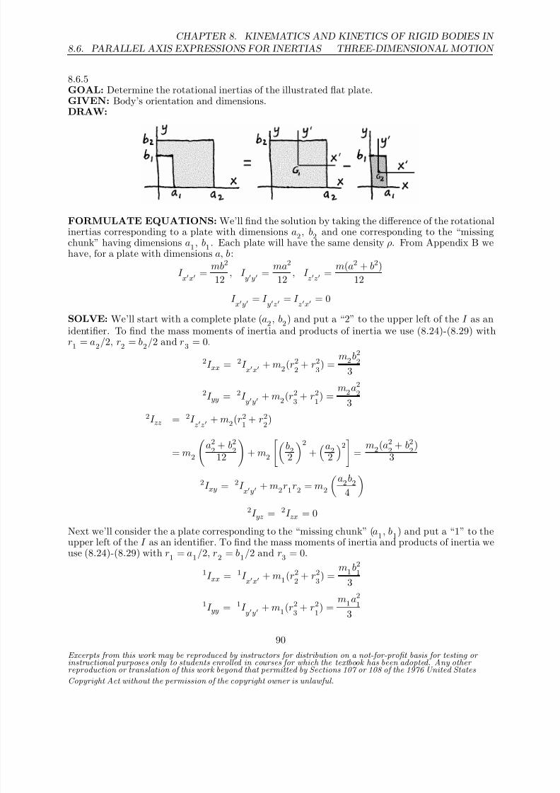
8/21/2019 Kinematics and kinetics of rigidbodies
http://slidepdf.com/reader/full/kinematics-and-kinetics-of-rigidbodies 56/190
8.6. PARALLEL AXIS EXPRESSIONS FOR INERTIAS
CHAPTER 8. KINEMATICS AND KINETICS OF RIGID BODIES IN
THREE-DIMENSIONAL MOTION
8.6.5GOAL: Determine the rotational inertias of the illustrated flat plate.GIVEN: Body’s orientation and dimensions.DRAW:
FORMULATE EQUATIONS: We’ll find the solution by taking the difference of the rotationalinertias corresponding to a plate with dimensions a2, b2 and one corresponding to the “missingchunk” having dimensions a1, b1 . Each plate will have the same density ρ. From Appendix B wehave, for a plate with dimensions a, b:
I xx =
mb2
12 , I yy =
ma2
12 , I zz =
m(a2 + b2)
12
I xy = I
yz = I zx = 0
SOLVE: We’ll start with a complete plate (a2 , b2) and put a “2” to the upper left of the I as anidentifier. To find the mass moments of inertia and products of inertia we use (8.24)-(8.29) withr1 = a2/2, r2 = b2/2 and r3 = 0.
2I xx = 2I xx
+ m2(r22
+ r23
) =m2b2
2
3
2I yy = 2I yy + m2(r2
3 + r2
1) =
m2a22
3
2I zz = 2I zz + m2(r21 + r22)
= m2
a22
+ b22
12
+ m2
b22
2
+a2
2
2 =
m2(a22
+ b22
)3
2I xy = 2I xy + m2r1r2 = m2
a2b2
4
2I yz = 2I zx = 0
Next we’ll consider the a plate corresponding to the “missing chunk” (a1 , b1) and put a “1” to theupper left of the I as an identifier. To find the mass moments of inertia and products of inertia we
use (8.24)-(8.29) with r1 = a1/2, r2 = b1/2 and r3 = 0.1I xx = 1I
xx + m1(r22
+ r23
) =m1b2
1
3
1I yy = 1I yy + m1(r2
3 + r2
1) =
m1a21
3
Excerpts from this work may be reproduced by instructors for distribution on a not-for-profit basis for testing or instructional purposes only to students enrolled in courses for which the textbook has been adopted. Any other reproduction or translation of this work beyond that permitted by Sections 107 or 108 of the 1976 United States
Copyright Act without the permission of the copyright owner is unlawful.
90

8/21/2019 Kinematics and kinetics of rigidbodies
http://slidepdf.com/reader/full/kinematics-and-kinetics-of-rigidbodies 57/190
CHAPTER 8. KINEMATICS AND KINETICS OF RIGID BODIES IN
THREE-DIMENSIONAL MOTION 8.6. PARALLEL AXIS EXPRESSIONS FOR INERTIAS
1I zz = 1I zz + m1(r2
1 + r2
2)
= m1
a21
+ b21
12
+ m1
b12
2
+a1
2
2 =
m1(a21
+ b21
)3
1
I xy =
1
I xy + m1r1r2 = m1 a1b1
4 1I yz = 1I zx = 0
We can now take the difference of the two sets of rotational inertias, using m1 = ρa1b1 andm2 = ρb1b2 to obtain
I xx =ρa2b3
23 − ρa1b3
13
I yy =ρb2a3
23 − ρb1a3
13
I zz = ρ(a32b2 + a2b32)3 − ρ(a31b1 + a1b31)
3
I xy =ρa2
2b22
4 − ρa21
b21
4
Excerpts from this work may be reproduced by instructors for distribution on a not-for-profit basis for testing or instructional purposes only to students enrolled in courses for which the textbook has been adopted. Any other reproduction or translation of this work beyond that permitted by Sections 107 or 108 of the 1976 United States
Copyright Act without the permission of the copyright owner is unlawful.
91

8/21/2019 Kinematics and kinetics of rigidbodies
http://slidepdf.com/reader/full/kinematics-and-kinetics-of-rigidbodies 58/190
8.6. PARALLEL AXIS EXPRESSIONS FOR INERTIAS
CHAPTER 8. KINEMATICS AND KINETICS OF RIGID BODIES IN
THREE-DIMENSIONAL MOTION
8.6.6GOAL: Determine the mass moments of inertia and products of inertia for the illustrated washeralong the x, y,z axes (which go through the body’s mass center). Express the results in terms of ρ.GIVEN: The outer radius of the washer is ro = 0.03 m, the inner radius is r
i = 0.02 m, and the
thickness is h = 0.006 m.
DRAW:
SOLVE: We may compute the inertias in cylindrical r, θ,z coordinates, with x = r cos θ, y = r sin θ,and x2 + y2 = r2. First, we’ll compute I zz .
I zz
= Bodyx2 + y2 dm =
h2
−h2
2π
0ro
ri
r2ρ r d r d θ d z
= ρ
h2
−h2
2π 0
r4o4 −
r4i4
dθ dz
= 2πρh
r4o4 −
r4i4
= 2πρ (0.006 m)
(0.03 m)4
4 − (0.02 m)4
4
I zz =
6.13×10⁻⁹ m5
ρ
Excerpts from this work may be reproduced by instructors for distribution on a not-for-profit basis for testing or instructional purposes only to students enrolled in courses for which the textbook has been adopted. Any other reproduction or translation of this work beyond that permitted by Sections 107 or 108 of the 1976 United States
Copyright Act without the permission of the copyright owner is unlawful.
92
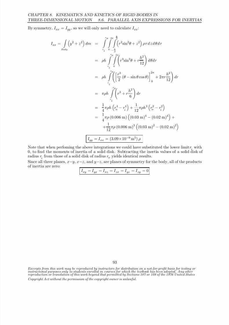
8/21/2019 Kinematics and kinetics of rigidbodies
http://slidepdf.com/reader/full/kinematics-and-kinetics-of-rigidbodies 59/190
CHAPTER 8. KINEMATICS AND KINETICS OF RIGID BODIES IN
THREE-DIMENSIONAL MOTION 8.6. PARALLEL AXIS EXPRESSIONS FOR INERTIAS
By symmetry, I xx = I yy , so we will only need to calculate I xx :
I xx =
Body
y2 + z2
dm =
ro ri
2π 0
h2
−h2
r2sin2θ + z2
ρ r d z d θ d r
= ρh
ro ri
2π 0
r3sin2θ + r h2
12
dθdr
= ρh
ro ri
r3
2 (θ − sin θ cos θ)
2π0
+ 2πrh2
12
dr
= πρh
ro ri
r3 + r
h2
6
dr
= 1
4πρh
r4o − r4
i +
1
12πρh3
r2o − r2
i = 1
4πρ (0.006 m)
(0.03 m)4 − (0.02 m)4
+
+ 1
12πρ (0.006 m)3
(0.03 m)2 − (0.02 m)2
I yy = I xx =
3.09×10⁻⁹ m5
ρ
Note that when perfoming the above integrations we could have substituted the lower limit ri with
0, to find the moments of inertia of a solid disk. Subtracting the inertia values of a solid disk of radius r
i from those of a solid disk of radius ro yields identical results.
Since all three planes, x−y, x−z, and y−z, are planes of symmetry for the body, all of the productsof inertia are zero:
I xy = I yx = I xz = I zx = I yz = I zy = 0
Excerpts from this work may be reproduced by instructors for distribution on a not-for-profit basis for testing or instructional purposes only to students enrolled in courses for which the textbook has been adopted. Any other reproduction or translation of this work beyond that permitted by Sections 107 or 108 of the 1976 United States
Copyright Act without the permission of the copyright owner is unlawful.
93

8/21/2019 Kinematics and kinetics of rigidbodies
http://slidepdf.com/reader/full/kinematics-and-kinetics-of-rigidbodies 60/190
8.6. PARALLEL AXIS EXPRESSIONS FOR INERTIAS
CHAPTER 8. KINEMATICS AND KINETICS OF RIGID BODIES IN
THREE-DIMENSIONAL MOTION
8.6.7GOAL: Determine the illustrated body’s mass moments of inertia and products of inertia alongthe given x, y, z axes in terms of the body’s mass m.GIVEN: Refer to the illustration.DRAW:
FORMULATE EQUATIONS:The mass moments of inertia for a three-dimensional rigid body about axes parallel to its centroidalaxes are of the form
I xx = I xx + m
r2y + r2z
, etc. (1)
Likewise, a three-dimensional rigid body’s products of inertia about axes parallel to its centroidalaxes have the form
I xy = I xy + mrxry , etc. (2)
SOLVE:A direct application of (1) gives us that the body’s moments of inertia are
(1) ⇒ I xx = 1
12m
b2 + (2b)2
+ m
b2 +
b
2
2
= 5
3mb2
(1) ⇒
I yy
= 1
12mb2 + b2 + m −
b
22
+ b
22
= 2
3mb2
(1) ⇒ I zz = 1
12m
b2 + (2b)2
+ m
− b
2
2
+ b2
= 5
3mb2
Excerpts from this work may be reproduced by instructors for distribution on a not-for-profit basis for testing or instructional purposes only to students enrolled in courses for which the textbook has been adopted. Any other reproduction or translation of this work beyond that permitted by Sections 107 or 108 of the 1976 United States
Copyright Act without the permission of the copyright owner is unlawful.
94

8/21/2019 Kinematics and kinetics of rigidbodies
http://slidepdf.com/reader/full/kinematics-and-kinetics-of-rigidbodies 61/190
CHAPTER 8. KINEMATICS AND KINETICS OF RIGID BODIES IN
THREE-DIMENSIONAL MOTION 8.6. PARALLEL AXIS EXPRESSIONS FOR INERTIAS
By symmetry, we see that I xy = I yx = I xz = I zx = I yz = I zy = 0. Hence, we find from (2) thatthe body’s products of inertia are
(2) ⇒ I xy = I yx = m
− b
2
(b) = −1
2mb2
(2) ⇒ I xz = I zx = m
− b
2
b
2
= −1
4mb2
(2) ⇒ I yz = I zy = m (b)
b
2
=
1
2mb2
The body’s mass moments of inertia and products of inertia are summarized as follows:
I xx = I zz = 53
mb2, I yy = 23
mb2
I xy = I yx = −I yz = −I zy = −1
2mb2, I xz = I zx = −1
4mb2
Excerpts from this work may be reproduced by instructors for distribution on a not-for-profit basis for testing or instructional purposes only to students enrolled in courses for which the textbook has been adopted. Any other reproduction or translation of this work beyond that permitted by Sections 107 or 108 of the 1976 United States
Copyright Act without the permission of the copyright owner is unlawful.
95

8/21/2019 Kinematics and kinetics of rigidbodies
http://slidepdf.com/reader/full/kinematics-and-kinetics-of-rigidbodies 62/190
8.6. PARALLEL AXIS EXPRESSIONS FOR INERTIAS
CHAPTER 8. KINEMATICS AND KINETICS OF RIGID BODIES IN
THREE-DIMENSIONAL MOTION
8.6.8GOAL: Determine the mass moments and products of inertia for the illustrated triangular prismGIVEN: Body’s orientation and dimensions.DRAW:
FORMULATE EQUATIONS: From Appendix B we have the rotational inertias about thebody’s mass center G of a flat right-triangle:
I xx = mb
2
18 , I yy = ma
2
18 , I zz = m(a
2
+ b
2
)18
I xy =
mab
36 , I
yz = I zx = 0
To find the mass moments of inertia and products of inertia we’ll use (8.24)-(8.29) with r1 = a3 ,
r2 = b3 and r3 = c
2 after determining the rotational inertias of a solid prism from those of the flatright-triangle.SOLVE:
The mass of a thin slice having thickness dz is ρab dz2 .
I xx =c
0 ρab3
36 + ρab2
z2 +
b3
2
dz = ρab
2
c
0 b26 + z2
dz
= ρab2
b2z6 + z3
3 c
0
I xx = ρabc
b2
12 + c2
6
= m
b2
6 + c2
3
From symmetry we have
I yy = ρabc
a26 + c2
12
= m
a2
3 + c26
I zz = m
a2
18 +
b2
18
+ m
a2
9 +
b2
9
= m
a2
6 +
b2
6
I zz = m
a2
6 + b2
6
= ρabc
a2
12 + b2
12
I xy = I xy + m
a
3
b
3
= −mab
36 +
mab
9 =
mab
12
Excerpts from this work may be reproduced by instructors for distribution on a not-for-profit basis for testing or instructional purposes only to students enrolled in courses for which the textbook has been adopted. Any other reproduction or translation of this work beyond that permitted by Sections 107 or 108 of the 1976 United States
Copyright Act without the permission of the copyright owner is unlawful.
96
8/21/2019 Kinematics and kinetics of rigidbodies
http://slidepdf.com/reader/full/kinematics-and-kinetics-of-rigidbodies 63/190
CHAPTER 8. KINEMATICS AND KINETICS OF RIGID BODIES IN
THREE-DIMENSIONAL MOTION 8.6. PARALLEL AXIS EXPRESSIONS FOR INERTIAS
I xy = mab12 = ρa2b2c
24
I yz = m
b
3
c
2
I yz = mbc6 = ρab2c2
12
From symmetry we have
I zx = mac6 = ρa2bc2
12
Excerpts from this work may be reproduced by instructors for distribution on a not-for-profit basis for testing or instructional purposes only to students enrolled in courses for which the textbook has been adopted. Any other reproduction or translation of this work beyond that permitted by Sections 107 or 108 of the 1976 United States
Copyright Act without the permission of the copyright owner is unlawful.
97

8/21/2019 Kinematics and kinetics of rigidbodies
http://slidepdf.com/reader/full/kinematics-and-kinetics-of-rigidbodies 64/190
8.6. PARALLEL AXIS EXPRESSIONS FOR INERTIAS
CHAPTER 8. KINEMATICS AND KINETICS OF RIGID BODIES IN
THREE-DIMENSIONAL MOTION
8.6.9GOAL: Determine I xx , I yy , I zz , and I xy for the illustrated body. Express the results in terms of both the areal density ρ and the body’s mass mc . Denote the mass of each half circular piece bym = 1
2 mcGIVEN: The body’s dimensions are given in the figure.
DRAW:
SOLVE: To determine the moments and products of inertia for the composite body, we will requiresome inertia values for a half-circular body. Consider a circle with normal axis z through its masscenter. Since the moment of inertia of a full circle with mass mc about an axis through its masscenter and in the plane of the circle is 1
4mcr2, that of a half circle through the same point is:
I parallel = 1
21
4 mcr2 = 1
21
4 (2m) r2 = 1
4 mr2
The moment of inertia of a full circle about an axis through its mass center and normal to theplane of the circle is 1
2mcr2, thus for a half circle through the same point :
I normal
= 1
2
1
2mcr2
=
1
2
1
2 (2m) r2
=
1
2mr2
By symmetry, I xx = I zz for the composite body. Thus we will only calculate I zz . Using the parallelaxis expressions of inertia for half circle A we obtain:
I Azz = I Azz
+ m
r2 + d2
= I Azz
+ mr2
= 1
2mr2 + mr2
= 3
2mr2
Excerpts from this work may be reproduced by instructors for distribution on a not-for-profit basis for testing or instructional purposes only to students enrolled in courses for which the textbook has been adopted. Any other reproduction or translation of this work beyond that permitted by Sections 107 or 108 of the 1976 United States
Copyright Act without the permission of the copyright owner is unlawful.
98

8/21/2019 Kinematics and kinetics of rigidbodies
http://slidepdf.com/reader/full/kinematics-and-kinetics-of-rigidbodies 65/190
CHAPTER 8. KINEMATICS AND KINETICS OF RIGID BODIES IN
THREE-DIMENSIONAL MOTION 8.6. PARALLEL AXIS EXPRESSIONS FOR INERTIAS
For half circle B :
I Bzz = I Bzz
+ mr2
= 1
4mr2 + mr2
=
5
4 mr2
Thus, for the composite body,
I zz = I Azz + I Bzz = 11
4 mr2
I xx = I zz = 118 mcr2 = 11
8 ρπr4
The moment of inertia about the y-axis is the same for both half circles. I yy is therefore quitestraightforward to compute,
I yy = I Ayy + I Byy = 1
4mr2 +
1
4mr2 =
1
2mr2
I yy = 14 mcr2 = 1
4 ρπr4
The product of inertia, I Bxy , will be zero since the y−z plane is a plane of symmetry for half circle
B (with normal x-axis). The product of inertia is then I xy = I Axy . One method of obtaining I Axyis to integrate over the half circle A using integration parameters x, y and the bounds x = 0 andx2 + (y − r)2 = r2. (⇒ x = 0 and x2 = 2yr − y2)
I Axy =
Body
xydm =
2r 0
√ 2yr−y2
0
xyρdxdy
= ρ
2r 0
2yr − y2
2 y dy
= ρ
8r4
3 − 2r4
= 2
3ρr4
Thus,
I xy = I Axy = 23 ρr4 = 2
3π mcr2
Excerpts from this work may be reproduced by instructors for distribution on a not-for-profit basis for testing or instructional purposes only to students enrolled in courses for which the textbook has been adopted. Any other reproduction or translation of this work beyond that permitted by Sections 107 or 108 of the 1976 United States
Copyright Act without the permission of the copyright owner is unlawful.
99

8/21/2019 Kinematics and kinetics of rigidbodies
http://slidepdf.com/reader/full/kinematics-and-kinetics-of-rigidbodies 66/190
8.6. PARALLEL AXIS EXPRESSIONS FOR INERTIAS
CHAPTER 8. KINEMATICS AND KINETICS OF RIGID BODIES IN
THREE-DIMENSIONAL MOTION
8.6.10GOAL: Determine the I xx, I yy , I zz and I xy for the illustrated body.GIVEN: Body’s orientation and shape. a = 0.1 m, b = 0.02m, c = 0.07m, d = 0.06 m. Thedensity of the large block is 800 kg /m3 and the density of the small block is 1000 kg /m3.DRAW:
FORMULATE EQUATIONS: We’ll solve this problem by breaking it up into two rectangularbodies, one with dimensions a, a, b and the other with dimensions e, e, d, where e = a − c and isintroduced for convenience. e = 0.03 m. From Appendix B we have:
I xx = m
a2 + b2
12
, I
yy = m
a2 + b2
12
, I
zz = m
a2 + a2
12
for the large block and
I xx
= m
d2 + e2
12
, I
yy = m
d2 + e2
12
, I
zz = m
e2 + e2
12
for the small block.To find the mass moments of inertia and products of inertia we use (8.24)-(8.29) with appropriate
values of r1 , r2 and r3 .SOLVE: Let’s first consider the body with dimensions a, a, b. We’ll put a “1” to the upper left of the I as an identifier.For this body r1 = a/2, r2 = a/2 and r3 = b/2.
1I xx = 1I xx + m1(r2
2 + r2
3)
= m1
a2 + b2
12
+ m1
a2 + b2
4
= m1
a2 + b2
3
1I yy = 1I
yy + m1(r23
+ r21
)
= m1 a2 + b2
12 + m1 a2 + b2
4 = m1 a2 + b2
3 1I zz = 1I
zz + m1(r21
+ r22
)
= m1
a2 + a2
12
+ m1
a2 + a2
4
= m1
a2 + a2
3
Excerpts from this work may be reproduced by instructors for distribution on a not-for-profit basis for testing or instructional purposes only to students enrolled in courses for which the textbook has been adopted. Any other reproduction or translation of this work beyond that permitted by Sections 107 or 108 of the 1976 United States
Copyright Act without the permission of the copyright owner is unlawful.
100

8/21/2019 Kinematics and kinetics of rigidbodies
http://slidepdf.com/reader/full/kinematics-and-kinetics-of-rigidbodies 67/190
CHAPTER 8. KINEMATICS AND KINETICS OF RIGID BODIES IN
THREE-DIMENSIONAL MOTION 8.6. PARALLEL AXIS EXPRESSIONS FOR INERTIAS
1I xy = 1I xy + m1r1r2 = m1
a2
4
Now we’ll consider the body with dimensions d, e, e. We’ll put a “2” to the upper left of the I asan identifier.For this body r1 = e/2, r2 = c + e/2 and r3 = b + d/2.
2
I xx = 2
I xx + m2(r22 + r
23)
= m2
d2 + e2
12
+ m2
c + e
2
2+
b + d2
22I yy = 2I
yy + m2(r2
3 + r2
1)
= m2
d2 + e2
12
+ m2
e2
2+
b + d2
22I zz = 2I
zz + m2(r21
+ r22
)
= m2 e
2
+ e
2
12 + m2 e22 + c + e222I xy = 2I
xy + m2r1r2 = m2
e
2
c +
e
2
The individual masses are given by
m1 = (800 kg/m3)(0.1m)(0.1m)(0.02 m) = 0.16kg
m2 = (1000kg/m3)(0.03 m)(0.03 m)(0.06m) = 0.054kg
Adding the rotational inertias together and evaluating for the given dimensional values gives us
I xx = 1I xx + 2I xx = (3.46×10⁻³ m2)(0.16 kg) + (1.01×10⁻² m2)(0.054 kg)
I yy = 1I yy + 2I yy = (3.46×10⁻³ m2)(0.16 kg) + (3.1×10⁻³ m2)(0.054 kg)
I zz = 1I zz + 2I zz = (6.6×10⁻³ m2)(0.16 kg) + (7.6×10⁻³ m2)(0.054 kg)
I xy = 1I xy + 2I xy = (2.5×10⁻³ m2)(0.16 kg) + (1.275×10⁻³ m2)(0.054kg)
I xx = 1.10×10⁻³ kg· m2 I yy = 7.22×10⁻⁴ kg· m2
I zz = 1.48×10⁻³ kg· m2 I xy = 4.69×10⁻⁴ kg· m2
Excerpts from this work may be reproduced by instructors for distribution on a not-for-profit basis for testing or instructional purposes only to students enrolled in courses for which the textbook has been adopted. Any other reproduction or translation of this work beyond that permitted by Sections 107 or 108 of the 1976 United States
Copyright Act without the permission of the copyright owner is unlawful.
101

8/21/2019 Kinematics and kinetics of rigidbodies
http://slidepdf.com/reader/full/kinematics-and-kinetics-of-rigidbodies 68/190
8.6. PARALLEL AXIS EXPRESSIONS FOR INERTIAS
CHAPTER 8. KINEMATICS AND KINETICS OF RIGID BODIES IN
THREE-DIMENSIONAL MOTION
8.6.11GOAL: Determine the mass moments of inertia and products of inertia along the x, y, z axes forthe the illustrated body. Then calculate the inertias about axes parallel to x, y,z that go throughthe body’s mass center. Express results in terms of the body’s mass m.GIVEN: The dimensions of the body are illustrated in the figure; we assume a linear density ρ.
DRAW:
FORMULATE EQUATIONS:First, we note the relationship between the mass and linear density of the body:
ρ = m
L1 + L2
(1)
Since moments and products of inertia are additive for composite bodies, we will treat the illustratedbody as two narrow rod segments and add the computed inertias of each segment to arrive at theresultant value for the entire body.SOLVE:
I xx =
Body
y2 + z2
dm =
L1 0
y2ρdy +
L2 0
z2ρdz = ρ y3
3
L1
0
+ ρ z3
3
L2
0
= ρ
3 L31
+ L32
= m3
L31+L3
2L1+L
2
I yy =
Body
x2 + z2
dm =
L1 0
(0 + 0) dm +
L2 0
z2ρdz = ρ z3
3
L2
0
= m3
L3
2L1+L
2
I zz = Bodyx2 + y2 dm =
L1
0 y2ρdy +
L2
0 (0 + 0) dm = ρ y3
3 L1
0
= m3
L3
1L1+L
2
The segment of length L1 has two planes of symmetry, the x−y plane and the y−z plane. Likewise,the segment of length L2 has two planes of symmetry, the x−z plane and the y−z plane. Since
Excerpts from this work may be reproduced by instructors for distribution on a not-for-profit basis for testing or instructional purposes only to students enrolled in courses for which the textbook has been adopted. Any other reproduction or translation of this work beyond that permitted by Sections 107 or 108 of the 1976 United States
Copyright Act without the permission of the copyright owner is unlawful.
102

8/21/2019 Kinematics and kinetics of rigidbodies
http://slidepdf.com/reader/full/kinematics-and-kinetics-of-rigidbodies 69/190
CHAPTER 8. KINEMATICS AND KINETICS OF RIGID BODIES IN
THREE-DIMENSIONAL MOTION 8.6. PARALLEL AXIS EXPRESSIONS FOR INERTIAS
each segment has two planes of symmetry all of the products of inertia are zero. (Also, note thatsince each segment is one dimensional, the product of dimensions appearing in the integral termsmust be zero.)
I xy = I yx = I xz = I zx = I yz = I zy = 0
Denote the segment of length L1 as mass m1 and the segment length L2 as mass m2 . The center
of mass of the body is located at:
rG
= m1
rG−1 + m2rG−2
m1 + m2
=m
L
1L1+L
2
−L
12
+ m
L
2L1+L
2
L2
2k
m
= −1
2
L21
L1 + L2
+ 1
2
L22
L1 + L2
k
Let x, y, z be a set of coordinate axes through the center of mass G that are parallel to thex,y ,z axes, respectively. Using the parallel axis expressions for moments and products of inertiawe obtain:
I xx = I xx − m
r22
+ r23
=
m
3
L31
+ L32
L1 + L2
− m
−1
2
L21
L1 + L2
2
+
1
2
L22
L1 + L2
2
= m(L
1+L
2)2
112
L41
+ L42
+ 1
3
L1L3
2 + L2L3
1
I yy = I yy − m
r21
+ r23
= m
3
L3
2
L1 + L2
− m
0 +
1
2
L22
L1 + L2
2
=mL3
2(L
1+L
2)2
112L2 + 1
3L1
I zz = I zz − m
r21
+ r22
= m
3
L3
1
L1 + L2
− m
0 +
−1
2
L21
L1 + L2
2
=mL3
1(L
1+L
2)2
112L1 + 1
3L2
I yz
= I zy
= I yz −
mr2
r3
= 0 − m
−1
2
L21
L1 + L2
1
2
L22
L1 + L2
= m4
L
1L2
L1+L
2
2
Excerpts from this work may be reproduced by instructors for distribution on a not-for-profit basis for testing or instructional purposes only to students enrolled in courses for which the textbook has been adopted. Any other reproduction or translation of this work beyond that permitted by Sections 107 or 108 of the 1976 United States
Copyright Act without the permission of the copyright owner is unlawful.
103

8/21/2019 Kinematics and kinetics of rigidbodies
http://slidepdf.com/reader/full/kinematics-and-kinetics-of-rigidbodies 70/190
8.6. PARALLEL AXIS EXPRESSIONS FOR INERTIAS
CHAPTER 8. KINEMATICS AND KINETICS OF RIGID BODIES IN
THREE-DIMENSIONAL MOTION
The center of mass of the body lies on the plane x = 0, and thus the y, z plane is also a plane of symmetry. The coordinate axis normal to this plane is the x axis. Therefore all products of inertiainvolving the x axis are zero:
I xy =
I yx = I
xz = I zx = 0
Alternatively, note that since the center of mass lies on the plane x = 0, r1 = 0.
Excerpts from this work may be reproduced by instructors for distribution on a not-for-profit basis for testing or instructional purposes only to students enrolled in courses for which the textbook has been adopted. Any other reproduction or translation of this work beyond that permitted by Sections 107 or 108 of the 1976 United States
Copyright Act without the permission of the copyright owner is unlawful.
104

8/21/2019 Kinematics and kinetics of rigidbodies
http://slidepdf.com/reader/full/kinematics-and-kinetics-of-rigidbodies 71/190
CHAPTER 8. KINEMATICS AND KINETICS OF RIGID BODIES IN
THREE-DIMENSIONAL MOTION 8.6. PARALLEL AXIS EXPRESSIONS FOR INERTIAS
8.6.12GOAL: Determine the moments and products of inertia along the x, y,z axes for the the illustratedtriangular body. Then calculate the inertias about axes parallel to x, y, z that go through the body’smass center. Express results in terms of the areal density ρ.GIVEN: The dimensions of the body are illustrated in the figure.
DRAW:
SOLVE: The borders of the triangular region are defined by the lines: x = 0, y = 0, and x =a(1 − y/b). The moments and products of inertia are computed by integrating over this region:
I xx =
Body
y2 + z2
dm =
b 0
a(1−y/b) 0
y2 + 0
ρdxdy
= ρ
b 0
a
1 − y
b
y2 dy
= ρa
b3
3 − b4
4b
= 112ρab3
I yy
may be found similarly, by reversing the order of integration in x and y and using integration
limits of 0 and b(1 − x/a) on y. By the symmetry of the problem we should find that I yy = 112ρa3b.
However, let’s proceed by maintaining the order above and performing the integration:
I yy =
Body
x2 + z2
dm =
b 0
a(1−y/b) 0
x2 + 0
ρdxdy
= ρ
b 0
a3
1 − yb
33
dy
= −ρa3b
12
1 − y
b
4b
0
= 112ρa3b
For I zz :
I zz =
Body
x2 + y2
dm =
b 0
a(1−y/b) 0
x2 + y2
ρdxdy
Excerpts from this work may be reproduced by instructors for distribution on a not-for-profit basis for testing or instructional purposes only to students enrolled in courses for which the textbook has been adopted. Any other reproduction or translation of this work beyond that permitted by Sections 107 or 108 of the 1976 United States
Copyright Act without the permission of the copyright owner is unlawful.
105

8/21/2019 Kinematics and kinetics of rigidbodies
http://slidepdf.com/reader/full/kinematics-and-kinetics-of-rigidbodies 72/190
8.6. PARALLEL AXIS EXPRESSIONS FOR INERTIAS
CHAPTER 8. KINEMATICS AND KINETICS OF RIGID BODIES IN
THREE-DIMENSIONAL MOTION
Notice that this is just the sum of I xx and I yy (this is true for all planar figures). Thus,
I zz = I xx + I yy = 112 ρ
ab3 + a3b
Since the x−y plane is a plane of symmetry for the body, all products of inertia involving thenormal z-axis are zero:
I xz = I zx = I yz = I zy = 0
The remaining products of inertia are:
I xy = I yx =
Body
xy dm =
b 0
a(1−y/b) 0
xyρdxdy
= ρ
b 0
a2
1 − yb
22
y dy
= ρ a2
2 b2
2 −
2b2
3
+ b2
4 = 1
24ρa2b2
To determine the moments and products of inertia about the center of mass, we first need todetermine its location.
rG
= 1
m
Body
r dm = 2
ρab
b 0
a(1−y/b) 0
(xı + y ) ρdxdy
= 2
ab
b 0
a2
2
1 − y
b
2ı + a
1 − y
b
y
dy
= 2
ab
−a2b
6
1 − y
b
3
ı + a
y2
2 − y3
3b
b
0
= 1
3
a ı + b
Using our parallel axis expressions for inertias, with r1 = a/3, r2 = b/3, and r3 = 0 we have:
I xx = I xx − m
r22
+ r23
=
1
12ρab3 − ρab
2
b2
9
= 1
36 ρab3
I yy = I yy − mr21 + r
23 =
1
12 ρa3
b − ρab
2 a2
9 = 136 ρa
3
b
I zz = I zz − m
r21
+ r22
= I
xx + I yy = 1
36 ρ
ab3 + a3b
I yx
= I xy
= I xy − mr1r2 = 1
24ρa2b2 − ρab
2
a
3
b
3
= − 1
72 ρa2b2
Excerpts from this work may be reproduced by instructors for distribution on a not-for-profit basis for testing or instructional purposes only to students enrolled in courses for which the textbook has been adopted. Any other reproduction or translation of this work beyond that permitted by Sections 107 or 108 of the 1976 United States
Copyright Act without the permission of the copyright owner is unlawful.
106

8/21/2019 Kinematics and kinetics of rigidbodies
http://slidepdf.com/reader/full/kinematics-and-kinetics-of-rigidbodies 73/190
CHAPTER 8. KINEMATICS AND KINETICS OF RIGID BODIES IN
THREE-DIMENSIONAL MOTION 8.6. PARALLEL AXIS EXPRESSIONS FOR INERTIAS
Due to the fact that r3 = 0, or the fact that the z -axis is normal to the plane of symmetry throughthe mass center, all other products of inertia are zero.
I xz =
I zx =
I yz =
I zy = 0
Excerpts from this work may be reproduced by instructors for distribution on a not-for-profit basis for testing or instructional purposes only to students enrolled in courses for which the textbook has been adopted. Any other reproduction or translation of this work beyond that permitted by Sections 107 or 108 of the 1976 United States
Copyright Act without the permission of the copyright owner is unlawful.
107
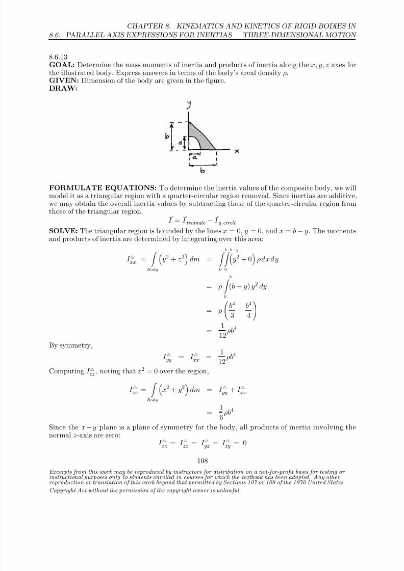
8/21/2019 Kinematics and kinetics of rigidbodies
http://slidepdf.com/reader/full/kinematics-and-kinetics-of-rigidbodies 74/190
8.6. PARALLEL AXIS EXPRESSIONS FOR INERTIAS
CHAPTER 8. KINEMATICS AND KINETICS OF RIGID BODIES IN
THREE-DIMENSIONAL MOTION
8.6.13GOAL: Determine the mass moments of inertia and products of inertia along the x, y, z axes forthe illustrated body. Express answers in terms of the body’s areal density ρ.GIVEN: Dimension of the body are given in the figure.DRAW:
FORMULATE EQUATIONS: To determine the inertia values of the composite body, we willmodel it as a triangular region with a quarter-circular region removed. Since inertias are additive,we may obtain the overall inertia values by subtracting those of the quarter-circular region fromthose of the triangular region.
I =
I triangle −
I q .circle
SOLVE: The triangular region is bounded by the lines x = 0, y = 0, and x = b − y. The momentsand products of inertia are determined by integrating over this area:
I xx =
Body
y2 + z2
dm =
b 0
b−y 0
y2 + 0
ρdxdy
= ρ
b 0
(b − y) y2 dy
= ρ
b4
3 − b4
4
= 1
12ρb4
By symmetry,
I yy = I xx = 1
12ρb4
Computing I zz , noting that z2 = 0 over the region,
I zz = Bodyx2 + y2 dm = I yy + I xx
= 1
6ρb4
Since the x−y plane is a plane of symmetry for the body, all products of inertia involving thenormal z-axis are zero:
I xz = I zx = I yz = I zy = 0
Excerpts from this work may be reproduced by instructors for distribution on a not-for-profit basis for testing or instructional purposes only to students enrolled in courses for which the textbook has been adopted. Any other reproduction or translation of this work beyond that permitted by Sections 107 or 108 of the 1976 United States
Copyright Act without the permission of the copyright owner is unlawful.
108

8/21/2019 Kinematics and kinetics of rigidbodies
http://slidepdf.com/reader/full/kinematics-and-kinetics-of-rigidbodies 75/190
CHAPTER 8. KINEMATICS AND KINETICS OF RIGID BODIES IN
THREE-DIMENSIONAL MOTION 8.6. PARALLEL AXIS EXPRESSIONS FOR INERTIAS
Computing I xy = I yx for the triangular region,
I xy = I yx =
Body
xy dm =
b 0
b−y 0
xyρdxdy
= ρ
b 0
(b − y)
2
2 y dy
= ρ
b4
4 − b4
3 +
b4
8
= 1
24ρb4
The quarter-circular area may be defined using polar r, θ coordinates, with x = r cos θ, y = r sin θ,and r2 = x2 + y2. The bounds on the region are 0 ≤ r ≤ a and 0 ≤ θ ≤ π/2. In r, θ coordinates,the differential area may be written as dA = dr(rdθ), thus the differential mass unit becomesdm = ρ r dr dθ.
I xx =
Body
y2 + z2
dm =
π2
0
a 0
(r sin θ)2 ρ r d r d θ
= ρ
π2
0
a4
4 sin2θ dθ
= ρa4
8 (θ − sin θ cos θ)
π2
0
= 1
16ρπa4
By symmetry,
I yy = I xx = 1
16ρπa4
Now for I zz ,
I zz =
Body
x2 + y2
dm =
π2
0
a 0
r2ρ r d r d θ
= ρ
π2
0
a4
4 dθ
= 1
8ρπa4
The x−y plane is a plane of symmetry and thus all moments of inertia involving the normal z-axisare zero:
I xz = I zx = I yz = I zy = 0
Excerpts from this work may be reproduced by instructors for distribution on a not-for-profit basis for testing or instructional purposes only to students enrolled in courses for which the textbook has been adopted. Any other reproduction or translation of this work beyond that permitted by Sections 107 or 108 of the 1976 United States
Copyright Act without the permission of the copyright owner is unlawful.
109

8/21/2019 Kinematics and kinetics of rigidbodies
http://slidepdf.com/reader/full/kinematics-and-kinetics-of-rigidbodies 76/190
8.6. PARALLEL AXIS EXPRESSIONS FOR INERTIAS
CHAPTER 8. KINEMATICS AND KINETICS OF RIGID BODIES IN
THREE-DIMENSIONAL MOTION
The remaining products of inertia are:
I xy = I yx =
Body
xydm =
π2
0
a 0
r2 sin θ cos θρ rdrdθ
= ρ a4
4
π2
0
sin θ cos θ dθ
= ρa4
8 sin2θ
π2
0
= 1
8ρa4
The moments and products of inertia of the composite body are obtained by subtracting the inertiasof the quarter-circular region from the respective inertias of the triangular region:
I xx = I xx − I xx = 112ρb4 − 1
16ρπa4
I yy = I yy − I yy = 112ρb4 − 1
16ρπa4
I zz = I zz − I zz = 16ρb4 − 1
8ρπa4
I xy = I xy − I xy = 124ρb4 − 1
8ρa4
I yx = I xy = 124ρb4 − 1
8ρa4
By symmetry, all products of inertia involving the z -axis are zero:
I xz = I zx = I yz = I zy = 0
Excerpts from this work may be reproduced by instructors for distribution on a not-for-profit basis for testing or instructional purposes only to students enrolled in courses for which the textbook has been adopted. Any other reproduction or translation of this work beyond that permitted by Sections 107 or 108 of the 1976 United States
Copyright Act without the permission of the copyright owner is unlawful.
110

8/21/2019 Kinematics and kinetics of rigidbodies
http://slidepdf.com/reader/full/kinematics-and-kinetics-of-rigidbodies 77/190
CHAPTER 8. KINEMATICS AND KINETICS OF RIGID BODIES IN
THREE-DIMENSIONAL MOTION 8.6. PARALLEL AXIS EXPRESSIONS FOR INERTIAS
8.6.14GOAL: Determine the rotational inertias of the illustrated body.GIVEN: Body’s orientation. a = 0.1 m, b = 0.25m, c = 0.15m, d = 0.1 m, e = 0.1 m, f = 0.2 m,g = 0.15 m. Body’s density is ρ and mass is m.DRAW:
FORMULATE EQUATIONS: We’ll solve this problem by breaking it up into two rectangularbodies, one with dimensions a, b, c and the other with dimensions c, e, g. From Appendix B wehave:
I xx = m
c2 + b2
12
, I
yy = m
a2 + c2
12
, I
zz = m
a2 + b2
12
To find the mass moments of inertia and products of inertia we use (8.24)-(8.29) with appropriatevalues of r1 , r2 and r3 .SOLVE: Let’s first consider the body with dimensions a, b, c. We’ll put a “1” to the upper left of the I as an identifier.For this body r1 = a/2, r2 = b/2 and r3 = −c/2.
1I xx = 1I xx + m1(r2
2 + r2
3)
= m1
c2 + b2
12
+ m1
c2 + b2
4
= m1
c2 + b2
3
1I yy = 1I
yy + m1(r23
+ r21
)
= m1
a2 + c2
12
+ m1
a2 + c2
4
= m1
a2 + c2
3
1I zz = 1I
zz + m1(r2
1 + r2
2)
= m1 a2 + b2
12 + m1 a2 + b2
4 = m1 a2 + b2
3 1I xy = 1I
xy + m1r1r2 = m1
ab
4
1I yz = 1I yz + m1r2r3 = −m1
cb
4
Excerpts from this work may be reproduced by instructors for distribution on a not-for-profit basis for testing or instructional purposes only to students enrolled in courses for which the textbook has been adopted. Any other reproduction or translation of this work beyond that permitted by Sections 107 or 108 of the 1976 United States
Copyright Act without the permission of the copyright owner is unlawful.
111
8/21/2019 Kinematics and kinetics of rigidbodies
http://slidepdf.com/reader/full/kinematics-and-kinetics-of-rigidbodies 78/190
8.6. PARALLEL AXIS EXPRESSIONS FOR INERTIAS
CHAPTER 8. KINEMATICS AND KINETICS OF RIGID BODIES IN
THREE-DIMENSIONAL MOTION
1I zx = 1I zx + m1r3r1 = −m1
ac
4
Now we’ll consider the body with dimensions c, e, g. We’ll put a “2” to the upper left of the I asan identifier.For this body r1 = a + e/2, r2 = d + g/2 and r3 = −c/2.
2I xx = 2I xx
+ m2
(r2
2
+ r2
3
)
= m2
c2 + g2
12
+ m2
c2
2+
d + g2
22I yy = 2I
yy + m2(r23
+ r21
)
= m2
e2 + c2
12
+ m2
c2
2+
a + e2
22I zz = 2I
zz + m2(r21
+ r22
)
= m2 e2 + g2
12 + m2 d +
g
22
+ a +
e
222I xy = 2I
xy + m2r1r2 = m2
a +
e
2
d +
g
2
2I yz = 2I yz + m2r2r3 = m2
d +
g
2
− c
2
2I zx = 2I zx
+ m2r3r1 = m2
− c
2
a +
e
2
The individual masses are given by
m1 = 3.75×10⁻³ρ, m2 = 2.25×10⁻³ρ
Adding the rotational inertias together and evaluating for the given dimensional values gives usI xx = 1I xx + 2I xx = (1.96×10⁻⁴ m5)ρ
I yy = 1I yy + 2I yy = (1.1×10⁻⁴ m5)ρ
I zz = 1I zz + 2I zz = (2.16×10⁻⁴ m5)ρ
I xy = 1I xy + 2I xy = (8.25×10⁻⁵ m5)ρ
I yz = 1I yz + 2I yz = (−6.469×10⁻⁵ m5)ρ
I zx = 1I zx + 2I zx = (−3.94×10⁻⁵ m5)ρ
Finally, evaluating in terms of the object’s mass, m = (abc + ceg)ρ = (6.0×10⁻³ m3)ρ, gives us ourfinal results:
I xx = (3.27×10⁻² m2)m, I yy = (1.83×10⁻² m2)m, I zz = (3.60×10⁻² m2)m
Excerpts from this work may be reproduced by instructors for distribution on a not-for-profit basis for testing or instructional purposes only to students enrolled in courses for which the textbook has been adopted. Any other reproduction or translation of this work beyond that permitted by Sections 107 or 108 of the 1976 United States
Copyright Act without the permission of the copyright owner is unlawful.
112

8/21/2019 Kinematics and kinetics of rigidbodies
http://slidepdf.com/reader/full/kinematics-and-kinetics-of-rigidbodies 79/190
CHAPTER 8. KINEMATICS AND KINETICS OF RIGID BODIES IN
THREE-DIMENSIONAL MOTION 8.6. PARALLEL AXIS EXPRESSIONS FOR INERTIAS
I xy = (1.375×10⁻² m2)m, I yz = (−1.078×10⁻² m2)m, I zx = (−6.56×10⁻³ m2)m
Excerpts from this work may be reproduced by instructors for distribution on a not-for-profit basis for testing or instructional purposes only to students enrolled in courses for which the textbook has been adopted. Any other reproduction or translation of this work beyond that permitted by Sections 107 or 108 of the 1976 United States
Copyright Act without the permission of the copyright owner is unlawful.
113

8/21/2019 Kinematics and kinetics of rigidbodies
http://slidepdf.com/reader/full/kinematics-and-kinetics-of-rigidbodies 80/190
8.6. PARALLEL AXIS EXPRESSIONS FOR INERTIAS
CHAPTER 8. KINEMATICS AND KINETICS OF RIGID BODIES IN
THREE-DIMENSIONAL MOTION
8.6.15GOAL: Determine I xx, I xy , and I zz , for the illustrated body. Express the results in terms of boththe areal density ρ and the body’s mass m. Denote the mass of each half-circular piece by m
hc and
the mass of the rectangular piece by mr .GIVEN: The body’s dimensions are given in the figure.
DRAW:
FORMULATE EQUATIONS: We’ll use the rotational inertia formulas for a half-circle and flatrectangular body from Appendix B and then apply the parallel axis theorem.SOLVE: We’ll first look at Body A (the left half-circle) then B (the right half-circle) and finallythe rectangular piece C that joins the two half-circles.Body A:
A
I xx =
1
2 mhc b
22
=
1
8 mhcb2
d is the distance from the y axis to the body’s mass center.Using the parallel axis theorem gives us
AI xx = AI
xx − m
hcd2
and finally
AI xx = AI xx
+ mhc
d2 +
b
2
2
= 1
8m
hcb2 + m
hc
b
2
2
= 3
8m
hcb2
AI zz = AI zz + m
hc
b
2
2
= 1
4m
hc
b
2
2
+ mhc
b
2
2
= 5
16m
hcb2
Because Body A lies in the y ,z plane I xy = 0.Body B :We’ll again use x, y, z to refer to axes through that body’s mass center. From observation wehave the same value for BI xx as for Body A:
BI xx = 3
8m
hcb2
Excerpts from this work may be reproduced by instructors for distribution on a not-for-profit basis for testing or instructional purposes only to students enrolled in courses for which the textbook has been adopted. Any other reproduction or translation of this work beyond that permitted by Sections 107 or 108 of the 1976 United States
Copyright Act without the permission of the copyright owner is unlawful.
114

8/21/2019 Kinematics and kinetics of rigidbodies
http://slidepdf.com/reader/full/kinematics-and-kinetics-of-rigidbodies 81/190
CHAPTER 8. KINEMATICS AND KINETICS OF RIGID BODIES IN
THREE-DIMENSIONAL MOTION 8.6. PARALLEL AXIS EXPRESSIONS FOR INERTIAS
BI zz = BI zz + m
hc
b2
2+ a2
= 116m
hcb2 + m
hc
b2
2+ a2
= 5
16mhcb2
+ mhca2
BI xy = mhc
a
b
2
=
mhc
ab
2
Body C :C I xx = mrb2/3
C I zz = 1
3mr (a2 + b2)
C I xy = mr
a
2
b
2
=
mrab
4
The masses of the individual pieces are given bymhc
= (0.1 m)2π/2 = (1.57×10⁻² m2)ρ
mr = (0.4m)(0.2 m)ρ = (8.00×10⁻² m2)ρ
I xx = AI xx + BI xx + C I xx= (1.57×10⁻² m2)ρ(2)
38
(0.2 m)2 + 1
3(8.00×10⁻² m2)ρ(0.2 m)2
=
1.54×10⁻³ m5
ρ
I zz = AI zz + BI zz + C I zz= (1.57×10⁻² m2)ρ
(2)
516
(0.2 m)2 + (0.4 m)2
+ 1
3(8.00×10⁻² m2)ρ
(0.4 m)2 + (0.2 m)2
= 8.24×10⁻³
m5 ρ
I xy = AI xy + BI xy + C I xy= (1.57×10⁻² m2)ρ (0.2m)(0.4m)
2 + (8.00×10⁻² m2)ρ (0.2m)(0.4m)4
=
2.23×10⁻³ m5
ρ
The total mass of the body is given by
mt = mr + 2mhc
= (0.111m2)ρ
I xx = 1.39×10⁻²mt I zz = 7.40×10⁻²mt I xy = 2.00×10⁻²mt
Excerpts from this work may be reproduced by instructors for distribution on a not-for-profit basis for testing or instructional purposes only to students enrolled in courses for which the textbook has been adopted. Any other reproduction or translation of this work beyond that permitted by Sections 107 or 108 of the 1976 United States
Copyright Act without the permission of the copyright owner is unlawful.
115

8/21/2019 Kinematics and kinetics of rigidbodies
http://slidepdf.com/reader/full/kinematics-and-kinetics-of-rigidbodies 82/190
8.7. ANGULAR MOMENTUM
CHAPTER 8. KINEMATICS AND KINETICS OF RIGID BODIES IN
THREE-DIMENSIONAL MOTION
8.7 Angular Momentum
Excerpts from this work may be reproduced by instructors for distribution on a not-for-profit basis for testing or instructional purposes only to students enrolled in courses for which the textbook has been adopted. Any other reproduction or translation of this work beyond that permitted by Sections 107 or 108 of the 1976 United States
Copyright Act without the permission of the copyright owner is unlawful.
116

8/21/2019 Kinematics and kinetics of rigidbodies
http://slidepdf.com/reader/full/kinematics-and-kinetics-of-rigidbodies 83/190
CHAPTER 8. KINEMATICS AND KINETICS OF RIGID BODIES IN
THREE-DIMENSIONAL MOTION 8.7. ANGULAR MOMENTUM
8.7.1GOAL: Determine the angular momentum of the illustrated body about the fixed point O .GIVEN: The body rotates about the Y -axis with angular speed ω, and has areal density ρ.DRAW:
FORMULATE EQUATIONS: Let x,y,z be a set of body-fixed axes with origin O. At theinstant illustrated, these axes are aligned with the ground-fixed X,Y,Z axes. The body rotatesabout the Y -axis with angular speed ω; thus the y and Y axes remain aligned and the angular
velocity may be expressed as:
ω = ω
. The angular momentum of the body about point O is then:
H O =
I XX
ω1 − I
XY ω2
− I XZ
ω3
ı +
I YY
ω2 − I
YZ ω3
− I YX
ω1
+
I ZZ
ω3 − I
ZX ω1
− I ZY
ω2
k
H O = −I
XY ω ı + I
Y Y ω − I
ZY ω
k
Once we have determined the relevant inertia values about the point O, we may substitute andsolve for the angular momentum.
SOLVE: We only need to determine I XY
, I Y Y
and I Y Z
. I Y Y
is easily found as the mass momentof inertia about the Y axis is simply that of two thin rods, with masses ρab, ρac and lengths b, c,respectively, rotated about their ends:
I Y Y
= (ρac)c2
3 +
(ρab)b2
3 =
ρa(b3 + c3)
3
Using the appropriate equations from (8.21)-(8.29) lets us determine the products of inertia. Eachrectangle has no product of inertia when evaluated about its mass center and thus the only finiteproducts of inertia come about because we’re shifting our attention from each plate’s mass centerto the point O.
I XY
= ρ(ab)a
2
−b
2
= −ρa2b2
4
I Y Z
= ρ(ac)a
2
c
2 =
ρa2c2
4
H O =
ab24
ı + b3 + c33
− ac24
k
ρaω
Excerpts from this work may be reproduced by instructors for distribution on a not-for-profit basis for testing or instructional purposes only to students enrolled in courses for which the textbook has been adopted. Any other reproduction or translation of this work beyond that permitted by Sections 107 or 108 of the 1976 United States
Copyright Act without the permission of the copyright owner is unlawful.
117
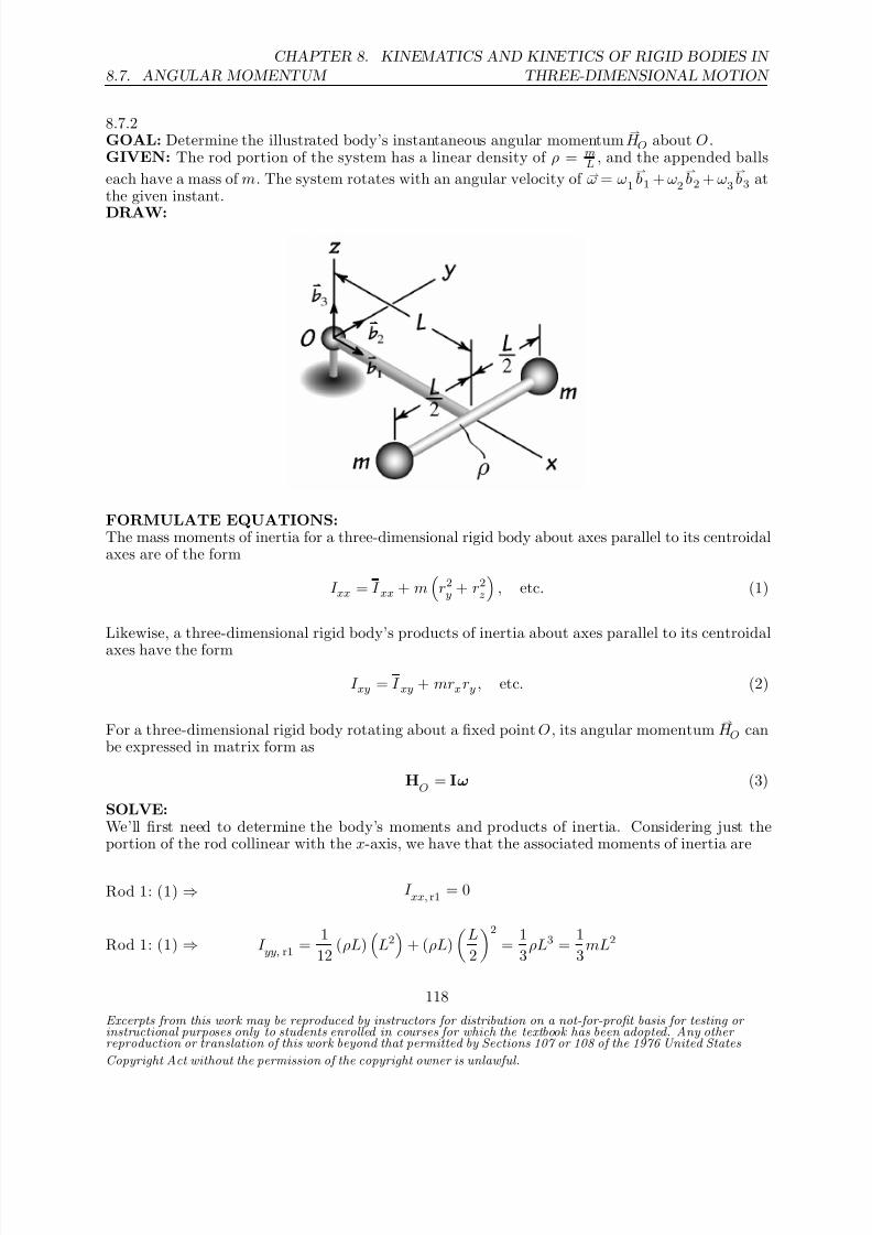
8/21/2019 Kinematics and kinetics of rigidbodies
http://slidepdf.com/reader/full/kinematics-and-kinetics-of-rigidbodies 84/190
8.7. ANGULAR MOMENTUM
CHAPTER 8. KINEMATICS AND KINETICS OF RIGID BODIES IN
THREE-DIMENSIONAL MOTION
8.7.2GOAL: Determine the illustrated body’s instantaneous angular momentum
H O about O .
GIVEN: The rod portion of the system has a linear density of ρ = mL , and the appended balls
each have a mass of m. The system rotates with an angular velocity of ω = ω1
b1 + ω2
b2 + ω3
b3 at
the given instant.
DRAW:
FORMULATE EQUATIONS:The mass moments of inertia for a three-dimensional rigid body about axes parallel to its centroidalaxes are of the form
I xx = I xx + m
r2y + r2z
, etc. (1)
Likewise, a three-dimensional rigid body’s products of inertia about axes parallel to its centroidal
axes have the form
I xy = I xy + mrxry , etc. (2)
For a three-dimensional rigid body rotating about a fixed point O , its angular momentum H O can
be expressed in matrix form as
HO
= Iω (3)
SOLVE:We’ll first need to determine the body’s moments and products of inertia. Considering just theportion of the rod collinear with the x-axis, we have that the associated moments of inertia are
Rod 1: (1) ⇒ I xx, r1 = 0
Rod 1: (1) ⇒ I yy, r1 = 1
12 (ρL)
L2
+ (ρL)
L
2
2
= 1
3ρL3 =
1
3mL2
Excerpts from this work may be reproduced by instructors for distribution on a not-for-profit basis for testing or instructional purposes only to students enrolled in courses for which the textbook has been adopted. Any other reproduction or translation of this work beyond that permitted by Sections 107 or 108 of the 1976 United States
Copyright Act without the permission of the copyright owner is unlawful.
118

8/21/2019 Kinematics and kinetics of rigidbodies
http://slidepdf.com/reader/full/kinematics-and-kinetics-of-rigidbodies 85/190
CHAPTER 8. KINEMATICS AND KINETICS OF RIGID BODIES IN
THREE-DIMENSIONAL MOTION 8.7. ANGULAR MOMENTUM
Rod 1: (1) ⇒ I zz, r1 = 1
12 (ρL)
L2
+ (ρL)
L
2
2
= 1
3ρL3 =
1
3mL2
Similarly, the moments of inertia for the portion of the rod parallel to the y-axis are
Rod 2: (1) ⇒ I xx, r2 = 1
12 (ρL) L2 = 1
12 ρL3 = 1
12 mL2
Rod 2: (1) ⇒ I yy, r2 = (ρL) L2 = ρL3 = mL2
Rod 2: (1) ⇒ I zz, r2 = 1
12 (ρL)
L2
+ (ρL) L2 = 13
12ρL3 =
13
12mL2
Lastly, the moments of inertia corresponding to the balls are
Balls: (1) ⇒ I xx, b
= 2
mL
2
2 = 1
2mL2
Balls: (1) ⇒ I yy, b
= 2
mL2
= 2mL2
Balls: (1) ⇒ I zz, b
= 2
m
L2 +
L
2
2
= 5
2mL2
Thus, the moments of inertia for the entire system are given by
I xx = I xx, r1 + I xx, r2 + I xx, b
= 7
12mL2
I yy = I yy, r1 + I yy, r2 + I yy, b
= 10
3 mL2
I zz = I zz, r1 + I zz, r2 + I zz, b
= 47
12mL2
Let’s now move on to the body’s products of inertia. By virtue of the symmetry and thinnessof the rod, we have that I xy, r = I yx, r = I xz, r = I zx, r = I yz, r = I zy, r = 0. Furthermore, since
ry, r = rz, r = 0, it follows that I xy, r = I yx, r = I xz, r = I zx, r = I yz, r = I zy, r = 0. As for the appendedballs, it’s clear that I
xz, b = I
zx, b = I
yz, b = I
zy, b = 0 since r
z, b = 0. Also, I
xy, b = I
yx, b = 0
because the balls are positioned symmetrically about O along the y-axis. Therefore, the body’sproducts of inertia are all zero, which implies that I xx , I yy , and I zz are principal moments of inertia.
Excerpts from this work may be reproduced by instructors for distribution on a not-for-profit basis for testing or instructional purposes only to students enrolled in courses for which the textbook has been adopted. Any other reproduction or translation of this work beyond that permitted by Sections 107 or 108 of the 1976 United States
Copyright Act without the permission of the copyright owner is unlawful.
119

8/21/2019 Kinematics and kinetics of rigidbodies
http://slidepdf.com/reader/full/kinematics-and-kinetics-of-rigidbodies 86/190
8.7. ANGULAR MOMENTUM
CHAPTER 8. KINEMATICS AND KINETICS OF RIGID BODIES IN
THREE-DIMENSIONAL MOTION
Furthermore, the inertia matrix I is diagonal, and so it immediately follows from (3) that the body’sangular momentum about O at the given instant can be expressed in vector form as
(3) ⇒ H O = I xxω1
b1 + I yyω2
b2 + I zz ω3
b3
H O =
mL2
12
7ω1
b1 + 40ω2
b2 + 47ω3
b3
Excerpts from this work may be reproduced by instructors for distribution on a not-for-profit basis for testing or instructional purposes only to students enrolled in courses for which the textbook has been adopted. Any other reproduction or translation of this work beyond that permitted by Sections 107 or 108 of the 1976 United States
Copyright Act without the permission of the copyright owner is unlawful.
120

8/21/2019 Kinematics and kinetics of rigidbodies
http://slidepdf.com/reader/full/kinematics-and-kinetics-of-rigidbodies 87/190
CHAPTER 8. KINEMATICS AND KINETICS OF RIGID BODIES IN
THREE-DIMENSIONAL MOTION 8.7. ANGULAR MOMENTUM
8.7.3GOAL: Determine the angular momentum of the illustrated rectangular body about the fixedpoint O .GIVEN: The body rotates about the Z -axis with angular speed ω , and has mass m.DRAW:
FORMULATE EQUATIONS: Let x,y,z be a set of body-fixed axes with origin O. At theinstant illustrated, these axes are aligned with the ground-fixed X,Y,Z axes. The body rotatesabout the Z -axis with angular speed ω; thus the z and Z axes remain aligned and the angularvelocity may be expressed as: ω = ω
k . The angular momentum of the body about point O is then:
H O =
I xx ω1
− I xy ω2 − I xz ω3
ı +
I yy ω2 − I yz ω3
− I yx ω1
+
I zz ω3 − I zx ω1
− I zy ω2
k
H O = −I xzω ı − I yzω + I zz ω
k (1)
Once we have determined the relevant inertia values about the point O, we may substitute andsolve for the angular momentum.
SOLVE: The products of inertia about parallel axes through the center of mass G are all zero, dueto the symmetry of the body. The products of inertia about the point O may be computed fromthe parallel axis expressions for inertia.
I xz : I xz = I xz + mr1r3 = 0 + m
a
2
− b
2
= −1
4mab
I yz : I yz = I yz
+ mr2r3 = 0 + m
c
2
− b
2
= −1
4mcb
The moment of inertia about the z-axis through the mass center is: I zz = 1
12m
a2 + c2
. Usingthe parallel axis expressions for inertia again, we obtain:
I zz :I zz = I
zz + m
r21
+ r22
=
1
12m
a2 + c2
+ m
a
2
2
+
c
2
2
= 1
3m
a2 + c2
Excerpts from this work may be reproduced by instructors for distribution on a not-for-profit basis for testing or instructional purposes only to students enrolled in courses for which the textbook has been adopted. Any other reproduction or translation of this work beyond that permitted by Sections 107 or 108 of the 1976 United States
Copyright Act without the permission of the copyright owner is unlawful.
121

8/21/2019 Kinematics and kinetics of rigidbodies
http://slidepdf.com/reader/full/kinematics-and-kinetics-of-rigidbodies 88/190
8.7. ANGULAR MOMENTUM
CHAPTER 8. KINEMATICS AND KINETICS OF RIGID BODIES IN
THREE-DIMENSIONAL MOTION
Substituting into (1),
H O = mω
14 ab ı + 1
4 cb + 13
a2 + c2k
Excerpts from this work may be reproduced by instructors for distribution on a not-for-profit basis for testing or instructional purposes only to students enrolled in courses for which the textbook has been adopted. Any other reproduction or translation of this work beyond that permitted by Sections 107 or 108 of the 1976 United States
Copyright Act without the permission of the copyright owner is unlawful.
122
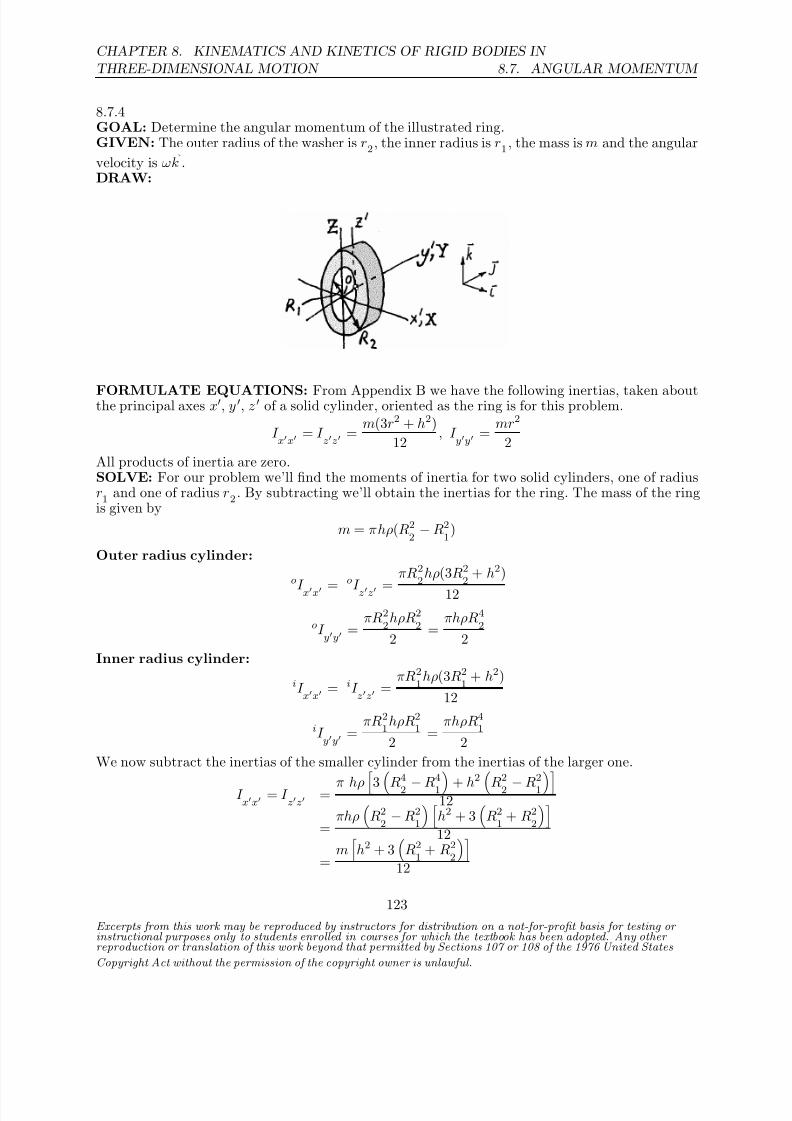
8/21/2019 Kinematics and kinetics of rigidbodies
http://slidepdf.com/reader/full/kinematics-and-kinetics-of-rigidbodies 89/190
CHAPTER 8. KINEMATICS AND KINETICS OF RIGID BODIES IN
THREE-DIMENSIONAL MOTION 8.7. ANGULAR MOMENTUM
8.7.4GOAL: Determine the angular momentum of the illustrated ring.GIVEN: The outer radius of the washer is r2, the inner radius is r1 , the mass is m and the angular
velocity is ωk .
DRAW:
FORMULATE EQUATIONS: From Appendix B we have the following inertias, taken aboutthe principal axes x, y , z of a solid cylinder, oriented as the ring is for this problem.
I xx = I
zz = m(3r2 + h2)
12 , I
yy = mr2
2
All products of inertia are zero.SOLVE: For our problem we’ll find the moments of inertia for two solid cylinders, one of radiusr1 and one of radius r2 . By subtracting we’ll obtain the inertias for the ring. The mass of the ringis given by
m = πhρ(R22 − R2
1)
Outer radius cylinder:
o
I xx = o
I zz =
πR22
hρ(3R22
+ h2)
12
oI yy =
πR22
hρR22
2 =
πhρR42
2
Inner radius cylinder:
iI xx =
iI zz =
πR21
hρ(3R21
+ h2)
12
iI yy =
πR21
hρR21
2 =
πhρR41
2
We now subtract the inertias of the smaller cylinder from the inertias of the larger one.
I xx = I
zz = π hρ 3 R42 − R
41 + h
2 R22 − R
21
12
=πhρ
R22 − R2
1
h2 + 3
R21
+ R22
12
=m
h2 + 3
R21
+ R22
12
Excerpts from this work may be reproduced by instructors for distribution on a not-for-profit basis for testing or instructional purposes only to students enrolled in courses for which the textbook has been adopted. Any other reproduction or translation of this work beyond that permitted by Sections 107 or 108 of the 1976 United States
Copyright Act without the permission of the copyright owner is unlawful.
123

8/21/2019 Kinematics and kinetics of rigidbodies
http://slidepdf.com/reader/full/kinematics-and-kinetics-of-rigidbodies 90/190
8.7. ANGULAR MOMENTUM
CHAPTER 8. KINEMATICS AND KINETICS OF RIGID BODIES IN
THREE-DIMENSIONAL MOTION
I yy
= I Y Y
=π hρ
R22 − R2
1
R21
+ R22
2
=m
R21
+ R22
2
Using the parallel axis theorem to find I XX
and I ZZ
we obtain
I XX
= I ZZ
= m h2 + 3 R21 + R22
12 + m
h2
2= mh2
3 + m(R21 + R22)
4
The products of inertia about X , Y , Z are zero from symmetry.The general expression for angular momentum (using ω = ω
k ) is therefore
H O =
mh2
3 +m(R2
1 + R2
2)
4
ωk
Excerpts from this work may be reproduced by instructors for distribution on a not-for-profit basis for testing or instructional purposes only to students enrolled in courses for which the textbook has been adopted. Any other reproduction or translation of this work beyond that permitted by Sections 107 or 108 of the 1976 United States
Copyright Act without the permission of the copyright owner is unlawful.
124
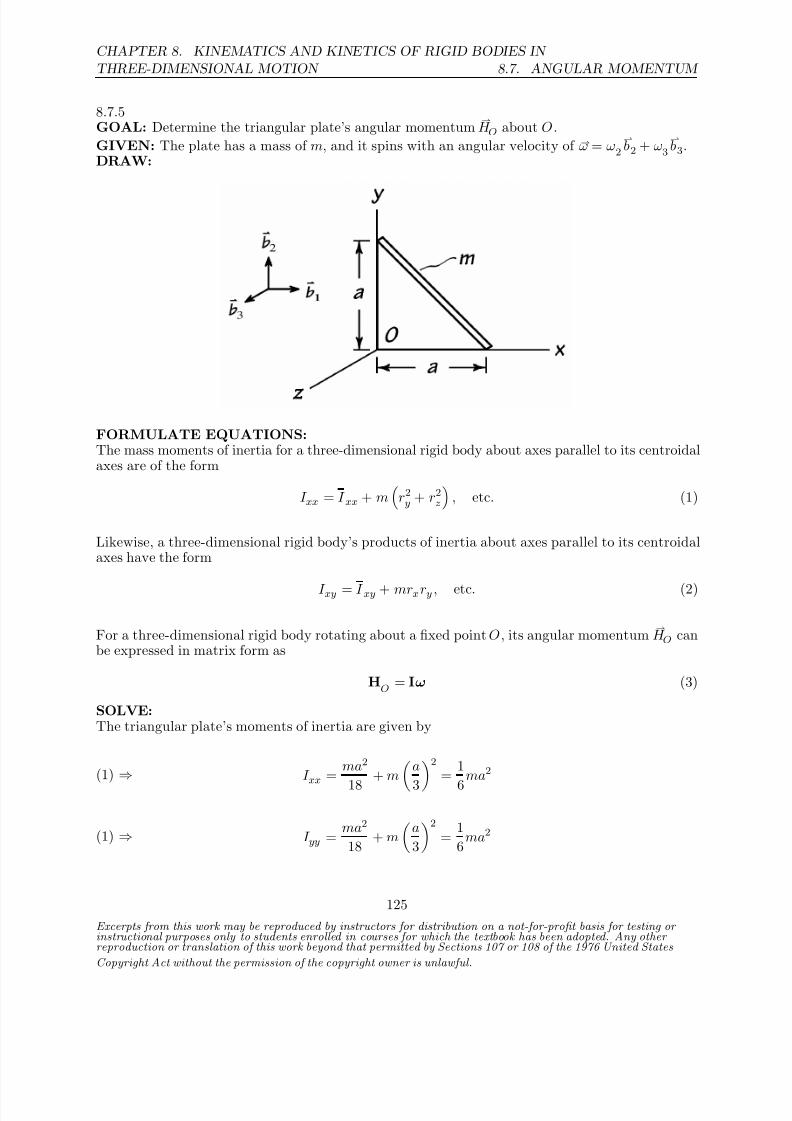
8/21/2019 Kinematics and kinetics of rigidbodies
http://slidepdf.com/reader/full/kinematics-and-kinetics-of-rigidbodies 91/190
CHAPTER 8. KINEMATICS AND KINETICS OF RIGID BODIES IN
THREE-DIMENSIONAL MOTION 8.7. ANGULAR MOMENTUM
8.7.5GOAL: Determine the triangular plate’s angular momentum
H O about O .
GIVEN: The plate has a mass of m, and it spins with an angular velocity of ω = ω2
b2 + ω3
b3.
DRAW:
FORMULATE EQUATIONS:The mass moments of inertia for a three-dimensional rigid body about axes parallel to its centroidalaxes are of the form
I xx = I xx + m
r2y + r2z
, etc. (1)
Likewise, a three-dimensional rigid body’s products of inertia about axes parallel to its centroidalaxes have the form
I xy = I xy + mrxry , etc. (2)
For a three-dimensional rigid body rotating about a fixed point O , its angular momentum H O can
be expressed in matrix form as
HO
= Iω (3)
SOLVE:The triangular plate’s moments of inertia are given by
(1) ⇒
I xx = ma2
18 + ma
32
= 1
6ma2
(1) ⇒ I yy = ma2
18 + m
a
3
2
= 1
6ma2
Excerpts from this work may be reproduced by instructors for distribution on a not-for-profit basis for testing or instructional purposes only to students enrolled in courses for which the textbook has been adopted. Any other reproduction or translation of this work beyond that permitted by Sections 107 or 108 of the 1976 United States
Copyright Act without the permission of the copyright owner is unlawful.
125

8/21/2019 Kinematics and kinetics of rigidbodies
http://slidepdf.com/reader/full/kinematics-and-kinetics-of-rigidbodies 92/190
8.7. ANGULAR MOMENTUM
CHAPTER 8. KINEMATICS AND KINETICS OF RIGID BODIES IN
THREE-DIMENSIONAL MOTION
(1) ⇒ I zz = m(a2 + a2)
18 + m
a
3
2
+
a
3
2
= 1
3ma2
Turning to the plate’s products of inertia, we notice that I xz = I zx = I yz = I zy = 0 because of the plate’s thinness. Furthermore, I xz = I zx = I yz = I zy = 0 since rz = 0, and hence the onlyproducts of inertia remaining are I
xy = I
yx:
(2) ⇒ I xy = I yx = −ma2
36 + m
a
3
a
3
=
3
36ma2
Using (3), we can then express the plate’s angular momentum about O as a column vector:
(3) ⇒ HO
= ma2
36
6 −3 0
−3 6 00 0 12
0
ω2ω3
=
ma2
36
−3ω2
6ω212ω3
Therefore, the plate’s angular momentum about O can be written in standard vector notation as
H O =
ma2
36
−3ω2
b1 + 6ω2
b2 + 12ω3
b3
Excerpts from this work may be reproduced by instructors for distribution on a not-for-profit basis for testing or instructional purposes only to students enrolled in courses for which the textbook has been adopted. Any other reproduction or translation of this work beyond that permitted by Sections 107 or 108 of the 1976 United States
Copyright Act without the permission of the copyright owner is unlawful.
126

8/21/2019 Kinematics and kinetics of rigidbodies
http://slidepdf.com/reader/full/kinematics-and-kinetics-of-rigidbodies 93/190
CHAPTER 8. KINEMATICS AND KINETICS OF RIGID BODIES IN
THREE-DIMENSIONAL MOTION 8.7. ANGULAR MOMENTUM
8.7.6GOAL: Calculate the angular momentum of the object about point O .GIVEN: The object has an angular velocity ω = (−6 + 10 ) rad/s.DRAW:
FORMULATE EQUATIONS: The angular momentum of the body about point O is given by:
H O =
I xx ω1
− I xy ω2 − I xz ω3
ı +
I yy ω2 − I yz ω3
− I yx ω1
+
I zz ω3
− I zx ω1 − I zy ω2
k
(1)
Once we have determined the relevant inertia values about the point O, we can substitute and solvefor the angular momentum.SOLVE: We’ll break the body into two pieces: AB and OC and identify the horizontal bar AB as“H ” and the vertical bar OC as “V .”
mH
= 2m
3 , m
V =
m
3
H I XX
= H I ZZ
=m
H L2
3 =
2mL2
9
H I Y Y
= H I XY
= H I Y Z
= H I ZX
= 0
V I XX
= V I Y Y
=m
H L2
3 =
mL2
9V I
ZZ = V I
XY = V I
Y Z = V I
ZX = 0
Our overall rotational inertias are given by the sum of the two components:
I XX
= 2mL2
9 +
mL2
9 =
mL2
3
I Y Y
= mL2
9 , I
ZZ =
2mL2
9
I XY
= I Y Z
= I ZX
= 0
Using these values in (1), along with ω1
=−
6 rad/s, ω2
= 10 rad/s, gives us
H O = I xx ω1ı + I yy ω2
+ I zz ω3
k
= mL2
3 (−6 rad/s)ı + mL2
9 (10 rad/s)
H O = mL2
−2ı + 10
9
rad/s
Excerpts from this work may be reproduced by instructors for distribution on a not-for-profit basis for testing or instructional purposes only to students enrolled in courses for which the textbook has been adopted. Any other reproduction or translation of this work beyond that permitted by Sections 107 or 108 of the 1976 United States
Copyright Act without the permission of the copyright owner is unlawful.
127

8/21/2019 Kinematics and kinetics of rigidbodies
http://slidepdf.com/reader/full/kinematics-and-kinetics-of-rigidbodies 94/190
8.7. ANGULAR MOMENTUM
CHAPTER 8. KINEMATICS AND KINETICS OF RIGID BODIES IN
THREE-DIMENSIONAL MOTION
8.7.7GOAL: Calculate the angular momentum of the thin disk D about G and O.GIVEN: The object has an angular velocity ω = (24ı − 76 ) rad/s. a = 0.3 m, r = 0.25m,m = 10 kg.DRAW:
FORMULATE EQUATIONS: The angular momentum expressions for the body when rotatingabout the points O and G are given by:
H G =
I xx ω1
− I xy ω2 − I xz ω3
ı +
I yy ω2 − I yz ω3
− I yx ω1
+
I zz ω3 − I zx ω1
− I zy ω2
k
(1)
H O =
I xx ω1
− I xy ω2 − I xz ω3
ı +
I yy ω2
− I yz ω3 − I yx ω1
+
I zz ω3 − I zx ω1 − I zy ω2 k(2)
where ωD = ω1ı + ω2
+ ω3
k = (24ı − 76 ) rad/s.
Once we have determined the relevant inertia values about the point O, we can substitute and solvefor the angular momentum.SOLVE:
I yy
= I zz
= mr2
4 , I
xx =
mr2
2 (3)
All products of inertia are zero.We can use the parallel axis theorem to find the corresponding rotational inertias about O :
I Y Y
= I ZZ
= mr2
4 + ma2, I
XX =
mr2
2 (4)
Due to symmetry the products of inertia are still zero.
(1), (3) ⇒ H G = mr2
2 ω1ı + mr2
4 ω2
= (10 kg)(0.25m)2
2 (24ı − 38 ) rad/s
= (7.5ı − 11.9 ) kg· m2/ s
Excerpts from this work may be reproduced by instructors for distribution on a not-for-profit basis for testing or instructional purposes only to students enrolled in courses for which the textbook has been adopted. Any other reproduction or translation of this work beyond that permitted by Sections 107 or 108 of the 1976 United States
Copyright Act without the permission of the copyright owner is unlawful.
128

8/21/2019 Kinematics and kinetics of rigidbodies
http://slidepdf.com/reader/full/kinematics-and-kinetics-of-rigidbodies 95/190
CHAPTER 8. KINEMATICS AND KINETICS OF RIGID BODIES IN
THREE-DIMENSIONAL MOTION 8.7. ANGULAR MOMENTUM
(2), (4) ⇒
H O = mr2
2 ω1ı + m
r2
4 + a2
ω2
= (10 kg)
(0.25m)2
2
24ı − 76
(0.25m)2
4 + (0.3 m)2
rad/s
= (7.5ı − 80.3 ) kg· m2/ s
Excerpts from this work may be reproduced by instructors for distribution on a not-for-profit basis for testing or instructional purposes only to students enrolled in courses for which the textbook has been adopted. Any other reproduction or translation of this work beyond that permitted by Sections 107 or 108 of the 1976 United States
Copyright Act without the permission of the copyright owner is unlawful.
129

8/21/2019 Kinematics and kinetics of rigidbodies
http://slidepdf.com/reader/full/kinematics-and-kinetics-of-rigidbodies 96/190
8.7. ANGULAR MOMENTUM
CHAPTER 8. KINEMATICS AND KINETICS OF RIGID BODIES IN
THREE-DIMENSIONAL MOTION
8.7.8GOAL: Calculate the angular momentum of the system about O.GIVEN: The framework has a mass of 0.005 kg and each arm has a length of h = 0.12 m. Thewheels have radii r = 0.007 m and negligible thickness. The framework rotates about the Y axisat 2.2 rad/s and the wheels rotate without slip. Each wheel has a mass of 0.001 kg.
DRAW:
FORMULATE EQUATIONS:
H O =
I xx ω1 − I xy ω2 − I xz ω3
ı +
I yy ω2 − I yz ω3
− I yx ω1
+
I zz ω3 − I zx ω1
− I zy ω2
k
(1)
Once we have determined the relevant inertia values about the point O, we can substitute and solvefor the angular momentum.SOLVE:Although the system contains several pieces, its symmetry allows us to simplify the analysis substan-tially. Each individual wheel will generate an angular momentum contribution due to its rotationabout the axis along the corresponding arm (the X axis for wheel A in the figure, for instance).
Because an identical contribution will be generated by each wheel, their sum will go to zero. Thuswe’re left with the same angular momentum as we’d have for the 3-arm assemble and attachedwheels rotating about the Y axis as a single rigid body.Each arm of the 3-arm body has mass moment of inertia about the Y axis of
I Y Y
=m3−a
3
h2
3
=
m3−ah2
9
For each wheel we have
I Y Y
= mwr2
4 + mwh2
The complete rotational inertia is therefore
I Y Y = 3 (0.005 kg)(0.12m)2
9 + (0.001 kg)(0.007m)
2
4 + (0.12m)2 = 6.72×10⁻⁵ kg· m2
Thus we have
H O =
6.72×10⁻⁵ kg· m2
(2.2 rad/s) = 1.48×10⁻⁴ kg· m2/ s
Excerpts from this work may be reproduced by instructors for distribution on a not-for-profit basis for testing or instructional purposes only to students enrolled in courses for which the textbook has been adopted. Any other reproduction or translation of this work beyond that permitted by Sections 107 or 108 of the 1976 United States
Copyright Act without the permission of the copyright owner is unlawful.
130

8/21/2019 Kinematics and kinetics of rigidbodies
http://slidepdf.com/reader/full/kinematics-and-kinetics-of-rigidbodies 97/190
CHAPTER 8. KINEMATICS AND KINETICS OF RIGID BODIES IN
THREE-DIMENSIONAL MOTION 8.7. ANGULAR MOMENTUM
8.7.9GOAL: Determine the angular momentum of the illustrated rectangular body about the fixedpoint O .GIVEN: The body rotates about the Z -axis with angular speed ω3 , and has a linear density ρ.DRAW:
FORMULATE EQUATIONS: Let x, y,z be a set of body-fixed axes with associated unit vectorsb1,
b2,
b3. The general expression for the angular momentum of the body about point O is:
H O =
I xx ω1
−I xy ω2
−I xz ω3 ı +
I yy ω2 − I yz ω3
− I yx ω1
+
I zz ω3 − I zx ω1
− I zy ω2
k
Letting ω1 = ω2 = 0 gives us
H O = (−I xz ı − I yz
+ I zz k )ω3
Once we have determined the relevant inertia values about the point O, we can substitute and solvefor the angular momentum.SOLVE: Denote the mass of the segment OA by m1 and the mass of the segment AB by m2 .
I zz =m1L2
1
3 + m2L2
1
I xz = m2L1
−L2
2
= −m2L1L2
2
I yz = 0
H O =
m2L1L2
2ı +
m1L2
1
3 + m2L2
1
k
ω3
Re-expressing m1 and m2 in terms of ρ, L1 , L2 gives us
H O = ρL1ω3
L22
2ı +
L21
3 + L1L2
k
Excerpts from this work may be reproduced by instructors for distribution on a not-for-profit basis for testing or instructional purposes only to students enrolled in courses for which the textbook has been adopted. Any other reproduction or translation of this work beyond that permitted by Sections 107 or 108 of the 1976 United States
Copyright Act without the permission of the copyright owner is unlawful.
131
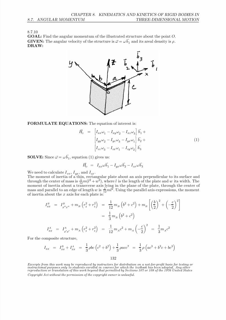
8/21/2019 Kinematics and kinetics of rigidbodies
http://slidepdf.com/reader/full/kinematics-and-kinetics-of-rigidbodies 98/190
8.7. ANGULAR MOMENTUM
CHAPTER 8. KINEMATICS AND KINETICS OF RIGID BODIES IN
THREE-DIMENSIONAL MOTION
8.7.10GOAL: Find the angular momentum of the illustrated structure about the point O.GIVEN: The angular velocity of the structure is ω = ω
b1 and its areal density is ρ.
DRAW:
FORMULATE EQUATIONS: The equation of interest is:
H O =
I xxω1
− I xyω2 − I xzω3
b1 +
I yy ω2 − I yz ω3
− I yxω1
b2 + (1)
I zz ω3 − I zxω1
− I zy ω2
b3
SOLVE: Since ω = ωb1, equation (1) gives us:
H
O = I xxω
b1
−I yxω
b2
−I zxω
b3
We need to calculate I xx, I yx , and I zx .The moment of inertia of a thin, rectangular plate about an axis perpendicular to its surface andthrough the center of mass is 1
12m(l2 + w2), where l is the length of the plate and w its width. Themoment of inertia about a transverse axis lying in the plane of the plate, through the center of mass and parallel to an edge of length w is 1
12ml2. Using the parallel axis expressions, the momentof inertia about the x axis for each plate is:
I Bxx = I Bxx
+ mB
r22
+ r23
=
1
12 mB
b2 + c2
+ mB
b
2
2
+
− c
2
2
= 1
3 m
B
b2 + c2
I Axx = I Axx
+ mA
r22
+ r23
=
1
12 mAc2 + mA
− c
2
2
= 1
3mAc2
For the composite structure,
I xx = I Bxx + I Axx = 1
3 ρbc
c2 + b2
+
1
3 ρacc2 =
1
3 ρ
ac3 + b3c + bc3
Excerpts from this work may be reproduced by instructors for distribution on a not-for-profit basis for testing or instructional purposes only to students enrolled in courses for which the textbook has been adopted. Any other reproduction or translation of this work beyond that permitted by Sections 107 or 108 of the 1976 United States
Copyright Act without the permission of the copyright owner is unlawful.
132

8/21/2019 Kinematics and kinetics of rigidbodies
http://slidepdf.com/reader/full/kinematics-and-kinetics-of-rigidbodies 99/190
CHAPTER 8. KINEMATICS AND KINETICS OF RIGID BODIES IN
THREE-DIMENSIONAL MOTION 8.7. ANGULAR MOMENTUM
The plane of symmetry for plate A is the x−z plane, so I Ayx = 0. The plane of symmetry for plate B
is the y−z plane, so I Byx = I Bzx = 0. The only remaining moment of inertia needed for substitution
into equation (1) is I Azx . Notice that all products of inertia about the center of mass of each plateare zero, thus by the parallel axis expressions we have:
I zx = I A
zx
= I A
zx + mAr3r1 = 0 + mA −
c
2a
2 = −
1
4 ρa2c2
Substition into (1) yields
H O = 1
3 ρ
ac3 + b3c + bc3
ωb1 + 1
4 ρa2c2ωb3
Excerpts from this work may be reproduced by instructors for distribution on a not-for-profit basis for testing or instructional purposes only to students enrolled in courses for which the textbook has been adopted. Any other reproduction or translation of this work beyond that permitted by Sections 107 or 108 of the 1976 United States
Copyright Act without the permission of the copyright owner is unlawful.
133

8/21/2019 Kinematics and kinetics of rigidbodies
http://slidepdf.com/reader/full/kinematics-and-kinetics-of-rigidbodies 100/190
8.7. ANGULAR MOMENTUM
CHAPTER 8. KINEMATICS AND KINETICS OF RIGID BODIES IN
THREE-DIMENSIONAL MOTION
8.7.11GOAL: Calculate the angular momentum of the system about point O.GIVEN: The system consists of four thin bars of length a, and has an angular velocity ω =
10 + 18k
rad/s.
DRAW:
FORMULATE EQUATIONS: The framework is symmetric in the x−y, x−z, and y−z planes,
thus all products of inertia about the mass center G are zero. The body-fixed x,y,z axes aretherefore a set of principle axes for the system, and the angular momentum may be expressed as:
H G
= I xxω1
b1 + I yyω2
b2 + I zz ω3
b3 (1)
To determine the angular momentum about the point O , we’ll use the expression,
H O = H G +
rG /O×mv
G (2)
SOLVE: We need to find the moments of inertia I xx, I yy , and I zz about the mass center. Assumethe bars have linear density ρ, and consider a differential mass unit dm = ρ dL, where dL is adifferential unit of length along a bar. For a unit change in length dL along the bar, there is acorresponding change
√ 2 dz along the z-axis. dm can thus be expressed as:
dm = ρ dL = ρ√ 2 dzSince the bars are one-dimensional, a single variable of integration (chosen to be z) is all that’sneeded to calculate the inertias. We’ll integrate over one of the bars, bar A in the diagram, andthen use our results to find the moments of inertia of the entire system. Note that the limits on zare 0 and a√
2. For I Ayy :
I Ayy =
BodyA
x2 + z2
dm =
a√ 2
0
0 + z2
ρ√
2 dz = 1
6ρa3
By symmetry, we expect I Azz = I Ayy . Although we could perform this integration over z with the
substitution y = a
√ 2 −z along bar A, it will be easier to just apply the same arguments as above
to the y-axis and integrate over y :
I Azz =
BodyA
x2 + y2
dm =
a√ 2
0
0 + y2
ρ√
2 dy = 1
6ρa3
Excerpts from this work may be reproduced by instructors for distribution on a not-for-profit basis for testing or instructional purposes only to students enrolled in courses for which the textbook has been adopted. Any other reproduction or translation of this work beyond that permitted by Sections 107 or 108 of the 1976 United States
Copyright Act without the permission of the copyright owner is unlawful.
134

8/21/2019 Kinematics and kinetics of rigidbodies
http://slidepdf.com/reader/full/kinematics-and-kinetics-of-rigidbodies 101/190
CHAPTER 8. KINEMATICS AND KINETICS OF RIGID BODIES IN
THREE-DIMENSIONAL MOTION 8.7. ANGULAR MOMENTUM
As x2 = 0 in the above equations, for I Axx we have:
I Axx =
BodyA
y2 + z2
dm = I Ayy + I Azz =
1
3ρa3
The moments of inertia of all four bars about the center of mass of the framework will be the same,
due to the symmetry of the system. Thus,
I xx = I Axx + I Bxx + I C xx + I Dxx = 4I Axx = 4
3ρa3
Similarly,
I yy = I zz = 2
3ρa3
The total mass of the system is M = ρ(4a), so rewriting these expressions in terms of M we obtain:
I xx = 1
3Ma2 I yy = I zz =
1
6M a2 (3)
There are, of course, a number of ways to determine the above moments of inertia. A secondmethod worth mentioning involves the use of symmetry arguments and the parallel axis expressions.Through the symmetry of the framework, we know that I yy = I zz , and since x2 = 0, we have
I xx = I yy + I zz = 2I yy = 2I zz . Thus, we only need to compute one of the inertia values, I xx. This
may be computed from the known moment of inertia of a thin bar about a transverse axis, 112mL2,the fact that there are 4 bars, and the parallal axis expressions:
I xx = 4
I xx + m
y2 + z2
= 4
1
12
M
4
a2 +
M
4
a
2
2
= 1
3M a2
where a2 is the distance from G to the center of any bar.
We are now ready to compute the angular momentum of the system. Note that at the giveninstant, the body-fixed
b1,
b2,
b3 unit vectors are aligned with the ground-fixed ı , ,
k unit vectors.
Returning to equation (1), with substitutions from (3),
H G = I xxω1
b1 + I yyω2
b2 + I zz ω3
b3
= 1
3M a2 (0) ı +
1
6M a2 (10) +
1
6M a2 (18)
k
= 5
3M a2 + 3M a2
k
Now substituting into equation (2), with vG
= ω×rG /O
H
O =
H
G + r
G /O×mv
G
= 5
3
M a2 + 3Ma2k + a
√ 2k
×M 10 + 18
k ×
a
√ 2k
= 20
3 M a2 + 3M a2
k
H O = M a2
203 + 3
k
Excerpts from this work may be reproduced by instructors for distribution on a not-for-profit basis for testing or instructional purposes only to students enrolled in courses for which the textbook has been adopted. Any other reproduction or translation of this work beyond that permitted by Sections 107 or 108 of the 1976 United States
Copyright Act without the permission of the copyright owner is unlawful.
135

8/21/2019 Kinematics and kinetics of rigidbodies
http://slidepdf.com/reader/full/kinematics-and-kinetics-of-rigidbodies 102/190
8.8. EQUATIONS OF MOTION FOR A THREE-DIMENSIONAL BODY
CHAPTER 8. KINEMATICS AND KINETICS OF RIGID BODIES IN
THREE-DIMENSIONAL MOTION
8.8 Equations of Motion for a Three-Dimensional Body
Excerpts from this work may be reproduced by instructors for distribution on a not-for-profit basis for testing or instructional purposes only to students enrolled in courses for which the textbook has been adopted. Any other reproduction or translation of this work beyond that permitted by Sections 107 or 108 of the 1976 United States
Copyright Act without the permission of the copyright owner is unlawful.
136

8/21/2019 Kinematics and kinetics of rigidbodies
http://slidepdf.com/reader/full/kinematics-and-kinetics-of-rigidbodies 103/190
CHAPTER 8. KINEMATICS AND KINETICS OF RIGID BODIES IN
THREE-DIMENSIONAL MOTION 8.8. EQUATIONS OF MOTION FOR A THREE-DIMENSIONAL BODY
8.8.1GOAL: Determine the direction of rotation that the student experiences after rotating the axle of the wheel as described.GIVEN: The wheel is given an intial spin ω about its axle in the direction indicated in the figure.There is no initial rotation of the swiveling platform. The student then rotates the wheel axle so
his right hand is directly above his left, with the axle of the wheel oriented vertically in space.DRAW:
SOLVE: Consider the mechanical “system” consisting of the student, wheel, and platform. Theonly external forces acting on the system are gravity and the reactions at the platform support.Since the platform swivels freely about the z-axis, no external moments may be applied to thesystem about this axis (or any point lying on the z-axis). The resultant of any external forcesacting on the platform must have a line of action that passes through the z -axis, or else be purelyvertical, parallel to this axis. Gravitational forces are assumed to be purely vertical as well.Since no external moments may be applied to our system about the z-axis, the angular momentum
of the system about any point lying on this axis is conserved in the
k -direction. This is clear fromthe angular momentum equation of motion:
M O =
d
dt
H O
⇒ 0 = H O ·
k
Excerpts from this work may be reproduced by instructors for distribution on a not-for-profit basis for testing or instructional purposes only to students enrolled in courses for which the textbook has been adopted. Any other reproduction or translation of this work beyond that permitted by Sections 107 or 108 of the 1976 United States
Copyright Act without the permission of the copyright owner is unlawful.
137

8/21/2019 Kinematics and kinetics of rigidbodies
http://slidepdf.com/reader/full/kinematics-and-kinetics-of-rigidbodies 104/190
8.8. EQUATIONS OF MOTION FOR A THREE-DIMENSIONAL BODY
CHAPTER 8. KINEMATICS AND KINETICS OF RIGID BODIES IN
THREE-DIMENSIONAL MOTION
Initially, the wheel axle is oriented horizontally, and the student is at rest. The system’s initialangular momentum component in the
k -direction is therefore zero, and it must remain zero for all
time. As the student tilts the axle of the wheel, bringing his right hand above the left, the wheelitself begins to acquire an angular momentum component in the positive
k direction. To counter
this positive gain, the student and platform must begin rotating in the opposite direction, at anangular speed which maintains the system’s overall angular momentum component in this direction
at zero. Thus,Student rotates in -z direction, or Ω is negative
In the solution above, we have only addressed the vertical direction, and have made no mention of the horizontal components. So the question might be asked, “What about the change in angularmomentum in the horizontal direction? Initially the wheel has a large component in this direction,but in the final orientation it has none.” The answer is that while the horizontal angular momen-tum components do change, the platform support provides the external moments allowing for thischange, and the student’s muscles provide the torques required for him to remain upright.
Excerpts from this work may be reproduced by instructors for distribution on a not-for-profit basis for testing or instructional purposes only to students enrolled in courses for which the textbook has been adopted. Any other reproduction or translation of this work beyond that permitted by Sections 107 or 108 of the 1976 United States
Copyright Act without the permission of the copyright owner is unlawful.
138

8/21/2019 Kinematics and kinetics of rigidbodies
http://slidepdf.com/reader/full/kinematics-and-kinetics-of-rigidbodies 105/190
CHAPTER 8. KINEMATICS AND KINETICS OF RIGID BODIES IN
THREE-DIMENSIONAL MOTION 8.8. EQUATIONS OF MOTION FOR A THREE-DIMENSIONAL BODY
8.8.2GOAL: Determine the forces and moments acting on the body at its fixed pivot O for the illustratedinstant.GIVEN: The system’s instantaneous angular velocity is a constant ω = ω2
b2 + ω3
b3.
DRAW:
FORMULATE EQUATIONS:For a three-dimensional rigid body rotating about a fixed point O , its angular momentum
H O can
be expressed in matrix form as
HO
= Iω (1)
The location of a three-dimensional composite body’s mass center is given by
r =
ni=1
mir i
ni=1
mi
(2)
With respect to body-fixed axes, a moment balance on a three-dimensional rigid body can bewritten as
M 1 = H 1 +
ω2H 3 − ω3H 2
(3)
M 2 = H 2 + ω3H 1 − ω1H 3 (4)M 3 = H 3 +
ω1H 2 − ω2H 1
(5)
Excerpts from this work may be reproduced by instructors for distribution on a not-for-profit basis for testing or instructional purposes only to students enrolled in courses for which the textbook has been adopted. Any other reproduction or translation of this work beyond that permitted by Sections 107 or 108 of the 1976 United States
Copyright Act without the permission of the copyright owner is unlawful.
139
8/21/2019 Kinematics and kinetics of rigidbodies
http://slidepdf.com/reader/full/kinematics-and-kinetics-of-rigidbodies 106/190
8.8. EQUATIONS OF MOTION FOR A THREE-DIMENSIONAL BODY
CHAPTER 8. KINEMATICS AND KINETICS OF RIGID BODIES IN
THREE-DIMENSIONAL MOTION
Balancing forces on a three-dimensional rigid body yields
F = maG (6)
The accelerations of two arbitrary, stationary points A and B on a rigid body are related accordingto
aB = aA + αAB × rB/A+ ωAB ×
ωAB × rB/A
(7)
SOLVE:By setting ω1 = 0, we find that the body’s angular momentum about O at the given instant is
(1) ⇒ H O = H 1
b1 + H 2
b2 + H 3
b3 =
mL2
12
40ω2
b2 + 47ω3
b3
The system’s mass center G is located at
(2) ⇒ rG/O= mL2
b1 + mL
b1 + mL
b1 + L2
b2 + mL
b1 − L2
b24m
= 78
Lb1
Thus, the moments exerted on the system at O are given by
FBD, b1: (3) ⇒ M 1 =
mL2
12
47ω2ω3
− 40ω2ω3
=
7
12mL2ω2ω3
FBD, b2: (4) ⇒ M 2 + 4mg
7
8L
= 0 ⇒ M 2 = −7
2mgL
FBD, b3: (5) ⇒ M 3 = 0
Since the body’s angular velocity is constant, we have that the acceleration of its mass center G is
(7) ⇒ aG =
ω2
b2 + ω3
b3
×
ω2
b2 + ω3
b3
×
7
8Lb1
= −7
8L
ω22
+ ω23
b1
Hence, a force balance gives us that the forces exerted on the body at O are
FBD, b1: (6) ⇒ F 1 = 4m
−7
8L
ω22
+ ω23
= −7
2mL
ω22
+ ω23
FBD, b2: (6) ⇒ F 2 = 0
Excerpts from this work may be reproduced by instructors for distribution on a not-for-profit basis for testing or instructional purposes only to students enrolled in courses for which the textbook has been adopted. Any other reproduction or translation of this work beyond that permitted by Sections 107 or 108 of the 1976 United States
Copyright Act without the permission of the copyright owner is unlawful.
140

8/21/2019 Kinematics and kinetics of rigidbodies
http://slidepdf.com/reader/full/kinematics-and-kinetics-of-rigidbodies 107/190
CHAPTER 8. KINEMATICS AND KINETICS OF RIGID BODIES IN
THREE-DIMENSIONAL MOTION 8.8. EQUATIONS OF MOTION FOR A THREE-DIMENSIONAL BODY
FBD, b3: (6) ⇒ F 3 − 4mg = 0 ⇒ F 3 = 4mg
To summarize, the forces and moments acting on the body at O for the illustrated instant are
F 1 = −7
2 mLω22 + ω23 , F 2 = 0, F 3 = 4mg
M 1 = 7
12mL2ω2ω3 , M 2 = −7
2mgL, M 3 = 0
Excerpts from this work may be reproduced by instructors for distribution on a not-for-profit basis for testing or instructional purposes only to students enrolled in courses for which the textbook has been adopted. Any other reproduction or translation of this work beyond that permitted by Sections 107 or 108 of the 1976 United States
Copyright Act without the permission of the copyright owner is unlawful.
141

8/21/2019 Kinematics and kinetics of rigidbodies
http://slidepdf.com/reader/full/kinematics-and-kinetics-of-rigidbodies 108/190
8.8. EQUATIONS OF MOTION FOR A THREE-DIMENSIONAL BODY
CHAPTER 8. KINEMATICS AND KINETICS OF RIGID BODIES IN
THREE-DIMENSIONAL MOTION
8.8.3GOAL: Determine the bearing forces for a rotating shaft.GIVEN: System configuration. Each lumped mass is 2 kg. a = 14cm and b = 11cm. ω =100 rad/s.DRAW:
FORMULATE EQUATIONS: We’ll use the a force balanceF = maG
and three moment balances about the shaft’s mass centerM 1 = H 1 + (ω2H 3 − ω3H 2)M 2 = H 2 + (ω3H 1 − ω1H 3)M 3 = H 3 + (ω1H 2 − ω2H 1)
where H G = H 1
b1 + H 2
b2 + H 3
b3
SOLVE: From (8.32) we have:
H G = −I xzω
b1 − I yzω
b2 + I zzω
b3
Excerpts from this work may be reproduced by instructors for distribution on a not-for-profit basis for testing or instructional purposes only to students enrolled in courses for which the textbook has been adopted. Any other reproduction or translation of this work beyond that permitted by Sections 107 or 108 of the 1976 United States
Copyright Act without the permission of the copyright owner is unlawful.
142

8/21/2019 Kinematics and kinetics of rigidbodies
http://slidepdf.com/reader/full/kinematics-and-kinetics-of-rigidbodies 109/190
CHAPTER 8. KINEMATICS AND KINETICS OF RIGID BODIES IN
THREE-DIMENSIONAL MOTION 8.8. EQUATIONS OF MOTION FOR A THREE-DIMENSIONAL BODY
I xz = m1
3a
2
(0) + m2
a
2
(−b) + m3
−a
2
(0) + m4
−3a
2
(b)
I xz = −ab
2 (m2 + 3m4) = −2mab
I yz = m1
3a
2
(−b) + m2
a
2
(0) + m3
−a
2
(b) + m4
−3a
2
(0)
I yz = −ab2
(3m1 + m3) = −2mab
I zz = b2(m1 + m2 + m3 + m4) = 4mb2
H G = 2mabω
b1 + 2mabω
b2 + 4mb2ω
b3
H 1 = 2mabω
H 2 = 2mabω
H 3 = 4mb2ω
M 1 = 0 − 2mabω2 = (R4 − R2)
5a
2 (1)
M 2 = 0 + 2mabω2 = (R1 − R3)5a
2 (2)
M 3 = 0 (3)
R1 + R3 = 0 (4)
R2 + R4 = 0 (5)
(5) → (1) ⇒ 5aR4 = −2mabω2 ⇒ R4 = −2mbω2
5 (6)
(6) → (5) ⇒ R2 = 2mbω2
5
(4) → (2) ⇒ 5aR1 = 2mabω2 ⇒ R1 = 2mbω2
5 (7)
(7) → (4) ⇒ R3 = −2mbω2
5
Using the given values:
R1 = 2(2 kg)(0.11 m)(100 rad/s)2
5 = 880 N
R3 = −880 N R2 = 880 N R4 = −880 N
Excerpts from this work may be reproduced by instructors for distribution on a not-for-profit basis for testing or instructional purposes only to students enrolled in courses for which the textbook has been adopted. Any other reproduction or translation of this work beyond that permitted by Sections 107 or 108 of the 1976 United States
Copyright Act without the permission of the copyright owner is unlawful.
143
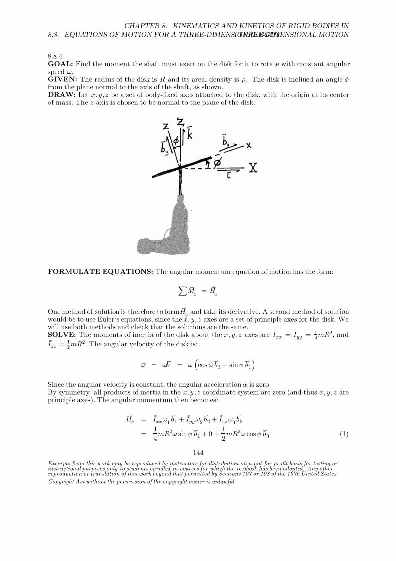
8/21/2019 Kinematics and kinetics of rigidbodies
http://slidepdf.com/reader/full/kinematics-and-kinetics-of-rigidbodies 110/190
8.8. EQUATIONS OF MOTION FOR A THREE-DIMENSIONAL BODY
CHAPTER 8. KINEMATICS AND KINETICS OF RIGID BODIES IN
THREE-DIMENSIONAL MOTION
8.8.4GOAL: Find the moment the shaft must exert on the disk for it to rotate with constant angularspeed ω.GIVEN: The radius of the disk is R and its areal density is ρ. The disk is inclined an angle φfrom the plane normal to the axis of the shaft, as shown.
DRAW: Let x,y,z be a set of body-fixed axes attached to the disk, with the origin at its centerof mass. The z-axis is chosen to be normal to the plane of the disk.
FORMULATE EQUATIONS: The angular momentum equation of motion has the form:
M
G
= H
G
One method of solution is therefore to form H
G and take its derivative. A second method of solution
would be to use Euler’s equations, since the x, y, z axes are a set of principle axes for the disk. Wewill use both methods and check that the solutions are the same.SOLVE: The moments of inertia of the disk about the x, y, z axes are I xx = I yy = 1
4mR2, and
I zz = 12mR2. The angular velocity of the disk is:
ω = ωk = ω
cos φ
b3 + sin φ
b1
Since the angular velocity is constant, the angular acceleration α is zero.
By symmetry, all products of inertia in the x, y,z coordinate system are zero (and thus x, y, z areprinciple axes). The angular momentum then becomes:
H
G = I xxω1
b1 + I yyω2
b2 + I zz ω3
b3
= 1
4mR2ω sin φ
b1 + 0 +
1
2mR2ω cos φ
b3 (1)
Excerpts from this work may be reproduced by instructors for distribution on a not-for-profit basis for testing or instructional purposes only to students enrolled in courses for which the textbook has been adopted. Any other reproduction or translation of this work beyond that permitted by Sections 107 or 108 of the 1976 United States
Copyright Act without the permission of the copyright owner is unlawful.
144

8/21/2019 Kinematics and kinetics of rigidbodies
http://slidepdf.com/reader/full/kinematics-and-kinetics-of-rigidbodies 111/190
CHAPTER 8. KINEMATICS AND KINETICS OF RIGID BODIES IN
THREE-DIMENSIONAL MOTION 8.8. EQUATIONS OF MOTION FOR A THREE-DIMENSIONAL BODY
Taking the derivative:
M
G =
H
G
N
= d
dt
S
H
G + ω×
H G
= 0 + ω
cos φ
b3 + sin φ
b1
×
1
4mR2ω sin φ
b1 +
1
2mR2ω cos φ
b3
= −14
mR2ω2 sin φ cos φ b2
Note that the unit vector b2 is always in the direction perpendicular to the axis of the shaft. With
m = ρπR2, we have:
M = − 14 ρπR4ω2 sin φ cos φ
b2
Since α and ω2 are zero, the only non-zero Euler’s equation is
M 2 = I yyα2 + ω1ω3
I xx − I zz
= 0 + (ω sin φ) (ω cos φ)
1
4mR2 − 1
2mR2
M 2 = − 14 ρπR4ω2 sin φ cos φ
which yields an identical result as above.
Excerpts from this work may be reproduced by instructors for distribution on a not-for-profit basis for testing or instructional purposes only to students enrolled in courses for which the textbook has been adopted. Any other reproduction or translation of this work beyond that permitted by Sections 107 or 108 of the 1976 United States
Copyright Act without the permission of the copyright owner is unlawful.
145

8/21/2019 Kinematics and kinetics of rigidbodies
http://slidepdf.com/reader/full/kinematics-and-kinetics-of-rigidbodies 112/190
8.8. EQUATIONS OF MOTION FOR A THREE-DIMENSIONAL BODY
CHAPTER 8. KINEMATICS AND KINETICS OF RIGID BODIES IN
THREE-DIMENSIONAL MOTION
8.8.5GOAL: Determine the bearing forces at A.GIVEN: System configuration. The shaft has a mass m1 and the half-disk has a mass m2.DRAW:
The primed axes are attached to the disk and rotate along with it, as do the unit vectors b1,
b2,
b3. The radius of the half-disk is given by r = d/2.
FORMULATE EQUATIONS: We’ll use the a force balanceF = maG
and three moment balances about the shaft’s mass center
M 1 = H 1 + (ω2H 3 − ω3H 2)
M 2 = H 2 + (ω3H 1 − ω1H 3)M 3 = H 3 + (ω1H 2 − ω2H 1)
where H G = H 1
b1 + H 2
b2 + H 3
b3
SOLVE: From (8.32) we have:
H G = −I zxω3
b1 − I yzω3
b2 + I zzω3
b3
I zx = I
yz = 0
I zz = m2r2
4
H G = m2r2ω3
4
b3
H 1 = 0, H 2 = 0, H 3 = m2r2ω
4
Excerpts from this work may be reproduced by instructors for distribution on a not-for-profit basis for testing or instructional purposes only to students enrolled in courses for which the textbook has been adopted. Any other reproduction or translation of this work beyond that permitted by Sections 107 or 108 of the 1976 United States
Copyright Act without the permission of the copyright owner is unlawful.
146

8/21/2019 Kinematics and kinetics of rigidbodies
http://slidepdf.com/reader/full/kinematics-and-kinetics-of-rigidbodies 113/190
CHAPTER 8. KINEMATICS AND KINETICS OF RIGID BODIES IN
THREE-DIMENSIONAL MOTION 8.8. EQUATIONS OF MOTION FOR A THREE-DIMENSIONAL BODY
where ω = ω1
b1 + ω2
b2 + ω3
b3, ω1 = ω2 = 0, ω3 = −ω.
We can now consider our force and moment balances.M 1 : 0 = (R4
− R2)3d
2 (1)
M 2 : 0 = (R1
− R3)3d
2 (2)
F 1 : R1 + R3
− (m1 + m2)g sin θ = 0 (3)
F 2 : R2 + R4
− (m1 + m2)g cos θ = −m2rω23
= −4m2rω23
3π (4)
(2), (3) ⇒ 2R1 = g(m1 + m2)sin θ
R1 = R3 = g(m1 + m2)sin θ
2
(1), (4)
⇒ 2R2 = g(m1 + m2)cos θ −
4m2
d
2
ω23
3π
R2 = R4 = g(m1 + m2)cos θ
2 − m2dω2
3π
Excerpts from this work may be reproduced by instructors for distribution on a not-for-profit basis for testing or instructional purposes only to students enrolled in courses for which the textbook has been adopted. Any other reproduction or translation of this work beyond that permitted by Sections 107 or 108 of the 1976 United States
Copyright Act without the permission of the copyright owner is unlawful.
147

8/21/2019 Kinematics and kinetics of rigidbodies
http://slidepdf.com/reader/full/kinematics-and-kinetics-of-rigidbodies 114/190
8.8. EQUATIONS OF MOTION FOR A THREE-DIMENSIONAL BODY
CHAPTER 8. KINEMATICS AND KINETICS OF RIGID BODIES IN
THREE-DIMENSIONAL MOTION
8.8.6GOAL: Find the rotational speed that allows θ to remain constant at 45. Is this the same resultas if all the mass were concentrated at C ?GIVEN: System configuration. L = 0.5 m, m = 2 kg.DRAW:
FORMULATE EQUATIONS:We’ll use the a force balance
F = maG
and three moment balances about the shaft’s mass centerM 1 = H 1 + (ω2H 3 − ω3H 2)M 2 = H 2 + (ω3H 1 − ω1H 3)
M 3 = H 3 + (ω1H 2 −
ω2H 1)
where H G = H 1
b1 + H 2
b2 + H 3
b3
SOLVE:(a) Using (8.33) and ω = ω
k gives us
H O = −I zxω
b1 − I yzω
b2 + I zzω
b3
I zz = mL2
12 + mL2 sin2 θ = mL2
1
12 + sin2 θ
I yz = mL2 cos θ sin θ
I zx = 0
H 1 = 0, H 2 = −mL2 cos θ sin θω, H 3 = mL2 112 + sin2 θ
.
H 1 = 0, H 2 = 0 and H 3 = 0.The first of our moment balance equations yields
M 1 = −ωH 2 = ω2mL2 cos θ sin θ = mgL sin θ
Excerpts from this work may be reproduced by instructors for distribution on a not-for-profit basis for testing or instructional purposes only to students enrolled in courses for which the textbook has been adopted. Any other reproduction or translation of this work beyond that permitted by Sections 107 or 108 of the 1976 United States
Copyright Act without the permission of the copyright owner is unlawful.
148

8/21/2019 Kinematics and kinetics of rigidbodies
http://slidepdf.com/reader/full/kinematics-and-kinetics-of-rigidbodies 115/190
CHAPTER 8. KINEMATICS AND KINETICS OF RIGID BODIES IN
THREE-DIMENSIONAL MOTION 8.8. EQUATIONS OF MOTION FOR A THREE-DIMENSIONAL BODY
ω2 = g
L cos θ =
9.81m/s2
(0.5m)(1/√
2)= 27.75 rad/s2
ω = 5.27 rad/s
(b) If all the mass were at C then we’d have:
I zz = mL2
sin2
θI yz = mL2 cos θ sin θ
I zx = 0
I yz is the same as in (a). Therefore the results for this case will not differ from those of (a).
Excerpts from this work may be reproduced by instructors for distribution on a not-for-profit basis for testing or instructional purposes only to students enrolled in courses for which the textbook has been adopted. Any other reproduction or translation of this work beyond that permitted by Sections 107 or 108 of the 1976 United States
Copyright Act without the permission of the copyright owner is unlawful.
149

8/21/2019 Kinematics and kinetics of rigidbodies
http://slidepdf.com/reader/full/kinematics-and-kinetics-of-rigidbodies 116/190
8.8. EQUATIONS OF MOTION FOR A THREE-DIMENSIONAL BODY
CHAPTER 8. KINEMATICS AND KINETICS OF RIGID BODIES IN
THREE-DIMENSIONAL MOTION
8.8.7GOAL: Determine the forces and moments exerted on the body at its fixed pivot O for theillustrated instant.GIVEN: The body’s instantaneous angular velocity is a constant ω = ω1
b1 + ω2
b2.
DRAW:
FORMULATE EQUATIONS:For a three-dimensional rigid body rotating about a fixed point O , its angular momentum
H O can
be expressed in matrix form as
HO
= Iω (1)
With respect to body-fixed axes, a moment balance on a three-dimensional rigid body can bewritten as
M 1 = H 1 +
ω2H 3 − ω3H 2
(2)
M 2 = H 2 +
ω3H 1 − ω1H 3
(3)
M 3 = H 3 +
ω1H 2 − ω2H 1
(4)
Balancing forces on a three-dimensional rigid body yields
F = m
aG (5)
Excerpts from this work may be reproduced by instructors for distribution on a not-for-profit basis for testing or instructional purposes only to students enrolled in courses for which the textbook has been adopted. Any other reproduction or translation of this work beyond that permitted by Sections 107 or 108 of the 1976 United States
Copyright Act without the permission of the copyright owner is unlawful.
150
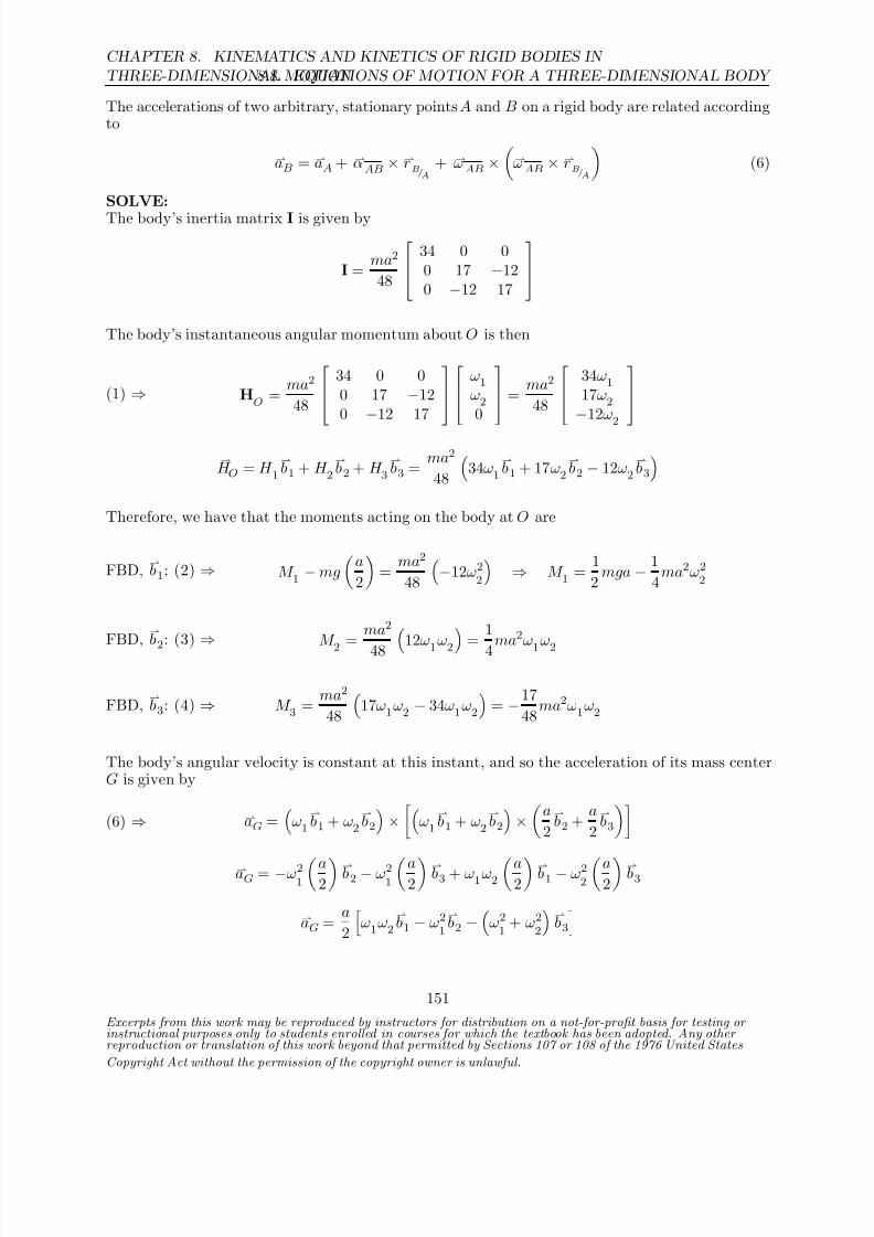
8/21/2019 Kinematics and kinetics of rigidbodies
http://slidepdf.com/reader/full/kinematics-and-kinetics-of-rigidbodies 117/190
CHAPTER 8. KINEMATICS AND KINETICS OF RIGID BODIES IN
THREE-DIMENSIONAL MOTION 8.8. EQUATIONS OF MOTION FOR A THREE-DIMENSIONAL BODY
The accelerations of two arbitrary, stationary points A and B on a rigid body are related accordingto
aB = aA + αAB × rB/A+ ωAB ×
ωAB × rB/A
(6)
SOLVE:
The body’s inertia matrix I is given by
I = ma2
48
34 0 0
0 17 −120 −12 17
The body’s instantaneous angular momentum about O is then
(1) ⇒ HO
= ma2
48
34 0 00 17 −120
−12 17
ω1ω20
= ma2
48
34ω117ω2
−12ω2
H O = H 1
b1 + H 2
b2 + H 3
b3 =
ma2
48
34ω1
b1 + 17ω2
b2 − 12ω2
b3
Therefore, we have that the moments acting on the body at O are
FBD, b1: (2) ⇒ M 1 − mg
a
2
=
ma2
48
−12ω2
2
⇒ M 1 =
1
2mga − 1
4ma2ω2
2
FBD, b2
: (3) ⇒
M 2
= ma2
48 12ω1
ω2 =
1
4ma2ω
1ω2
FBD, b3: (4) ⇒ M 3 =
ma2
48
17ω1ω2
− 34ω1ω2
= −17
48ma2ω1ω2
The body’s angular velocity is constant at this instant, and so the acceleration of its mass centerG is given by
(6) ⇒ aG =
ω1
b1 + ω2
b2
×
ω1
b1 + ω2
b2
×
a
2
b2 +
a
2
b3
aG = −ω21a
2 b2 − ω2
1a
2 b3 + ω1ω2
a2 b1 − ω2
2a
2 b3
aG = a
2
ω1ω2
b1 − ω2
1
b2 −
ω21
+ ω22
b3
Excerpts from this work may be reproduced by instructors for distribution on a not-for-profit basis for testing or instructional purposes only to students enrolled in courses for which the textbook has been adopted. Any other reproduction or translation of this work beyond that permitted by Sections 107 or 108 of the 1976 United States
Copyright Act without the permission of the copyright owner is unlawful.
151
8/21/2019 Kinematics and kinetics of rigidbodies
http://slidepdf.com/reader/full/kinematics-and-kinetics-of-rigidbodies 118/190
8.8. EQUATIONS OF MOTION FOR A THREE-DIMENSIONAL BODY
CHAPTER 8. KINEMATICS AND KINETICS OF RIGID BODIES IN
THREE-DIMENSIONAL MOTION
Thus, we find from balancing forces that the forces acting on the body at O are
FBD, b1: (5) ⇒ F 1 = m
1
2aω1ω2
=
1
2maω1ω2
FBD, b2: (5) ⇒ F 2 = m
−12
aω21
= −1
2maω2
1
FBD, b3: (5) ⇒ F 3 − mg = m
−1
2a
ω21
+ ω22
⇒ F 3 = mg − 1
2ma
ω21
+ ω22
In summary, the forces and moments exerted on the body at O for the illustrated instant are
F 1 = 1
2
maω1ω2 , F 2 =
−
1
2
maω21
, F 3 = mg
−
1
2
ma ω21
+ ω22
M 1 = 1
2mga − 1
4ma2ω2
2, M 2 =
1
4ma2ω1ω2, M 3 = −17
48ma2ω1ω2
Excerpts from this work may be reproduced by instructors for distribution on a not-for-profit basis for testing or instructional purposes only to students enrolled in courses for which the textbook has been adopted. Any other reproduction or translation of this work beyond that permitted by Sections 107 or 108 of the 1976 United States
Copyright Act without the permission of the copyright owner is unlawful.
152

8/21/2019 Kinematics and kinetics of rigidbodies
http://slidepdf.com/reader/full/kinematics-and-kinetics-of-rigidbodies 119/190
CHAPTER 8. KINEMATICS AND KINETICS OF RIGID BODIES IN
THREE-DIMENSIONAL MOTION 8.8. EQUATIONS OF MOTION FOR A THREE-DIMENSIONAL BODY
8.8.8GOAL: Describe the effect of lateral perturbations on the front wheel of a bicycle, when one isriding with no hands.DRAW:
ASSUME: Initially, the bike travels in a perfectly straight line and is perfectly upright.FORMULATE EQUATIONS: The sum of the moments about the mass center of the wheelmust equal the time rate of change of its angular momentum.
M G
= d
dt
H
G
SOLVE: Let ı be the forward vector, the right-to-left vector, and k the vertical up direction.
Initially, the front wheel has an angular momentum about its mass center with only one componentin the direction,
H G = H 2
. Assume that instead of riding with no hands, the handlebars areheld fixed by the rider. If the bike leans to the left (ω · ı = 0), the angular momentum vector
will tilt towards the ground, in the −k direction. Thus, the net moment on the wheel must also
have component in the −
k direction (provided by the rider’s grip on the handlebars). We conclude,therefore, that with no hands the wheel will have a tendency to turn in the positive
k direction,
or to the left.A similar argument shows that when the rider leans right, the wheel will turn to the right as well.
Leaning causes the bike to turn in the direction of the lean.
We may obtain the same result with an examination of a moment balance. Let b1,
b2,
b3 be a set
of body-fixed unit vectors initially aligned with ı , k . If the bike is traveling forward and leaning
to the right then its angular velocity may be represented as ω = ω1
b1 + ω2
b2 and the angular
momentum as H G = H 1
b1 + H 2
b2. Our third moment balance equation, corresponding to the
b3
component, is M 3 = I zz α3 + ω1ω2(I yy − I xx)
For a wheel, I yy > I xx . With no hands, and assuming a negligible resistance to turning at thecontact point between the wheel and ground, the net moment
M 3 will be zero and thus
α3 = −ω1ω2(I yy − I xx)
I zz< 0
Excerpts from this work may be reproduced by instructors for distribution on a not-for-profit basis for testing or instructional purposes only to students enrolled in courses for which the textbook has been adopted. Any other reproduction or translation of this work beyond that permitted by Sections 107 or 108 of the 1976 United States
Copyright Act without the permission of the copyright owner is unlawful.
153

8/21/2019 Kinematics and kinetics of rigidbodies
http://slidepdf.com/reader/full/kinematics-and-kinetics-of-rigidbodies 120/190
8.8. EQUATIONS OF MOTION FOR A THREE-DIMENSIONAL BODY
CHAPTER 8. KINEMATICS AND KINETICS OF RIGID BODIES IN
THREE-DIMENSIONAL MOTION
Thus the wheel turns to the right.The resulting motion of the wheel will tend to stabilize the bicycle. When the wheel turns, thecentripetal acceleration of the bicycle requires a frictional force between the wheels and groundtoward the center of curvature of the rider’s path. The moment this force exerts on the bicycle willtend to counter the moment due to gravity.
Excerpts from this work may be reproduced by instructors for distribution on a not-for-profit basis for testing or instructional purposes only to students enrolled in courses for which the textbook has been adopted. Any other reproduction or translation of this work beyond that permitted by Sections 107 or 108 of the 1976 United States
Copyright Act without the permission of the copyright owner is unlawful.
154
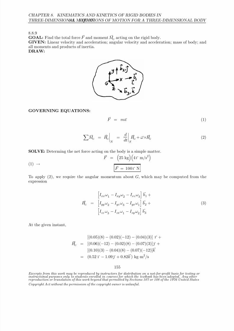
8/21/2019 Kinematics and kinetics of rigidbodies
http://slidepdf.com/reader/full/kinematics-and-kinetics-of-rigidbodies 121/190
CHAPTER 8. KINEMATICS AND KINETICS OF RIGID BODIES IN
THREE-DIMENSIONAL MOTION 8.8. EQUATIONS OF MOTION FOR A THREE-DIMENSIONAL BODY
8.8.9GOAL: Find the total force
F and moment
M
G acting on the rigid body.
GIVEN: Linear velocity and acceleration; angular velocity and acceleration; mass of body; andall moments and products of inertia.DRAW:
GOVERNING EQUATIONS:
F = ma (1)
M
G =
H
G
N
= d
dt
S
H
G + ω×
H G
(2)
SOLVE: Determing the net force acting on the body is a simple matter.
(1) →F =
25 kg
4ı m/s2
F = 100ı N
To apply (2), we require the angular momentum about G, which may be computed from theexpression
I xxω1
− I xyω2 − I xzω3
b1 +
H G =
I yyω2
− I yzω3 − I yxω1
b2 + (3)
I zz ω3 − I zxω1 − I zy ω2
b3
At the given instant,
[(0.05)(8) − (0.02)(−12) − (0.04)(3)] ı +
H G
= [(0.06)(−12) − (0.02)(8) − (0.07)(3)] +
[(0.10)(3) − (0.04)(8) − (0.07)(−12)]k
= (0.52 ı − 1.09 + 0.82k ) kg·m2/s
Excerpts from this work may be reproduced by instructors for distribution on a not-for-profit basis for testing or instructional purposes only to students enrolled in courses for which the textbook has been adopted. Any other reproduction or translation of this work beyond that permitted by Sections 107 or 108 of the 1976 United States
Copyright Act without the permission of the copyright owner is unlawful.
155

8/21/2019 Kinematics and kinetics of rigidbodies
http://slidepdf.com/reader/full/kinematics-and-kinetics-of-rigidbodies 122/190
8.8. EQUATIONS OF MOTION FOR A THREE-DIMENSIONAL BODY
CHAPTER 8. KINEMATICS AND KINETICS OF RIGID BODIES IN
THREE-DIMENSIONAL MOTION
Now, with the substitution of (3) into (2),
M G =
d
dt
S
H G +
ω×H G
=
I xxα1
− I xyα2 − I xzα3
b1 +
I yy α2 − I yz α3 − I yxα1 b2 +
I zz α3 − I zxα1
− I zy α2
b3 + ω×
H G
= [(0.05)(85) − (0.02)(−100) − (0.04)(30)] ı +
[(0.06)(−100) − (0.02)(85) − (0.07)(30)] +
[(0.10)(30) − (0.04)(85) − (0.07)(−100)]k +
(8 ı − 12 + 3k )×(0.52 ı − 1.09 + 0.82
k )
M
G =
−6.57 ı − 11.8 − 2.48
k
N·m
Note that the linear velocity does not appear in any of our computations.
Excerpts from this work may be reproduced by instructors for distribution on a not-for-profit basis for testing or instructional purposes only to students enrolled in courses for which the textbook has been adopted. Any other reproduction or translation of this work beyond that permitted by Sections 107 or 108 of the 1976 United States
Copyright Act without the permission of the copyright owner is unlawful.
156

8/21/2019 Kinematics and kinetics of rigidbodies
http://slidepdf.com/reader/full/kinematics-and-kinetics-of-rigidbodies 123/190
CHAPTER 8. KINEMATICS AND KINETICS OF RIGID BODIES IN
THREE-DIMENSIONAL MOTION 8.8. EQUATIONS OF MOTION FOR A THREE-DIMENSIONAL BODY
8.8.10GOAL: Determine the angular acceleration α of the T-bar, and the linear accelerations a
G and a
P
of the center of mass and point P , respectively, at the moment a given force F is applied.GIVEN: We’re given the mass m and dimension h for the body, and the applied force F with itslocation. The body is initially at rest.
DRAW:
ASSUME: The thickness of the T-bar is negligible and may be modeled as a slender rod.FORMULATE EQUATIONS: The center of mass of the T-bar is located at
xG = 1
m
2
3m(0) +
1
3m
−h
2
= −h
6 = −0.05 m (1)
Let x, y , z be a set of axes that pass through the mass center and are parallel with the given x, y ,z. The products of inertia about the x, y, z axes will all equal zero, due to the symmetry of thebody (and thus Euler’s equations are generally applicable). In addition, since the body is initiallyat rest, its angular velocity ω = 0 at the moment of interest. These conditions lead to a simplifiedversion of the angular equations of motion.
F = ma
G (2)
M G =
H G
N
= d
dt
S
H G +
ω×H G = I
xxα1ı + I
yyα2 + I
zzα3
k (3)
SOLVE: The moments of inertia about the x, y , z axes are
I xx =
2
3m
h
6
2
+ 1
12
m
3
h2 +
m
3
h
3
2
= 1
12mh2 = 0.0225 kg·m2
I yy
= 1
122
3m(2h)2 =
2
9mh2 = 0.06 kg·m2
I zz = I
xx + I yy =
11
36mh2 = 0.0825 kg·m2
The moment about the mass center is M G
= r ×F = (−0.15ı + 0.05 ) m×(−50ı + 40 + 20
k ) N = (ı + 3 − 3.5
k ) N·m
Excerpts from this work may be reproduced by instructors for distribution on a not-for-profit basis for testing or instructional purposes only to students enrolled in courses for which the textbook has been adopted. Any other reproduction or translation of this work beyond that permitted by Sections 107 or 108 of the 1976 United States
Copyright Act without the permission of the copyright owner is unlawful.
157

8/21/2019 Kinematics and kinetics of rigidbodies
http://slidepdf.com/reader/full/kinematics-and-kinetics-of-rigidbodies 124/190
8.8. EQUATIONS OF MOTION FOR A THREE-DIMENSIONAL BODY
CHAPTER 8. KINEMATICS AND KINETICS OF RIGID BODIES IN
THREE-DIMENSIONAL MOTION
Solving (3) for the angular acceleration components yields:
α1 = 1 N·m0.0225 kg·m2
= 44.4 rad/s2
α2 = 3 N·m0.0600 kg
·m2
= 50 rad/s2
α3 = −3.5 N·m2
0.0825 kg·m2 = −42.4 rad/s2
α = (44.4ı + 50 − 42.4k ) rad/s2
The center of mass acceleration is computed from (2),
aG = (−50ı + 40 + 20
k ) N
3 kg = (−16.7ı + 13.3 + 6.67
k ) m/s2
The acceleration of point P is then
aP = aG + α×rP /G
+ ω×ω×rP /G
= (−16.7ı + 13.3 + 6.67
k )m/s2 + (44.4ı + 50 − 42.4
k )rad/s2×(0.3ı + 0.05 ) m + 0
aP
= (−14.5ı + 0.606 − 6.11k ) m/s2
Excerpts from this work may be reproduced by instructors for distribution on a not-for-profit basis for testing or instructional purposes only to students enrolled in courses for which the textbook has been adopted. Any other reproduction or translation of this work beyond that permitted by Sections 107 or 108 of the 1976 United States
Copyright Act without the permission of the copyright owner is unlawful.
158

8/21/2019 Kinematics and kinetics of rigidbodies
http://slidepdf.com/reader/full/kinematics-and-kinetics-of-rigidbodies 125/190
CHAPTER 8. KINEMATICS AND KINETICS OF RIGID BODIES IN
THREE-DIMENSIONAL MOTION 8.8. EQUATIONS OF MOTION FOR A THREE-DIMENSIONAL BODY
8.8.11GOAL: Determine the angular speed ω, and its direction, that is required if the angle θ betweenthe vertical and shafts AC and B D is to remain constant at θ = 30, for a given rotational rate Ω.GIVEN: Each disk has mass m = 5 kg and radius R = 0.08 m; shafts AC and BD have lengthL1 = 0.20 m with spring attachment points at a distance L2 = 0.15 m from points C and D;
the length of link CD is L3 = 0.30 m, which is the same as the unstretched length of the spring(k = 320 N/m); Ω = 3 rad/s in the direction shown.DRAW:
ı
kb1 cos θ 0 − sin θb2 0 1 0b3 sin θ 0 cos θ
ASSUME: The mass of the spring and linkages is negligible.FORMULATE EQUATIONS: Since the system is symmetric, we can confine our work to onlyone disk and linkage. The linear and angular equations of motion for rigid bodies are
F = maG (1)
Excerpts from this work may be reproduced by instructors for distribution on a not-for-profit basis for testing or instructional purposes only to students enrolled in courses for which the textbook has been adopted. Any other reproduction or translation of this work beyond that permitted by Sections 107 or 108 of the 1976 United States
Copyright Act without the permission of the copyright owner is unlawful.
159

8/21/2019 Kinematics and kinetics of rigidbodies
http://slidepdf.com/reader/full/kinematics-and-kinetics-of-rigidbodies 126/190
8.8. EQUATIONS OF MOTION FOR A THREE-DIMENSIONAL BODY
CHAPTER 8. KINEMATICS AND KINETICS OF RIGID BODIES IN
THREE-DIMENSIONAL MOTION
M G =
H G
N
= d
dt
S
H G +
ω×H G (2)
SOLVE: The shaft is massless, so the only moments of inertia to consider are that of the disk.Since the disks are axisymmetric, we may use the shaft-fixed
b1,
b2,
b3 directions as “body-fixed”
unit vectors without loss of generality. All products of inertia are zero.
I xx = 14
mR2 I yy = 14
mR2 I zz = 12
mR2
With θ constant, the angular velocity of the disk is
ω = Ωk + ω
b3 = −Ωsin θ
b1 + (Ω cos θ + ω)
b3 (3)
The angular momentum of the disk is then
H G = −I xxΩsin θ
b1 + I zz (Ωcos θ + ω)
b3
= −1
4mR2Ωsin θ
b1 +
1
2mR2(Ωcos θ + ω)
b3 (4)
H G = −14 mR2Ωsin θ(Ωcos θb2) + 12 mR2(Ωcos θ + ω)(Ωsin θb2)
= 1
4mR2Ωsin θ(Ω cos θ + 2ω) (5)
Let the reaction force at point D be F xı + F y
+ F zk . The link is pinned at D so that there is no
moment in the b2-direction; the negligible mass of the shaft and the fact that the disk spins freely
about is axis indicates that there can be no moment about b3 either. Thus the reaction moment is
just M 1b1.
M G =
(r ×
F ) + M 1b1
= −L1
b3×(F x
ı + F y
+ F z
k ) + −(L1 − L2)
b3×(−2kL2 sin θ)
ı + M 1
b1= (L1F y + M 1)
b1 + [L1F z sin θ − L1F x cos θ + 2k(L1
− L2)L2 sin θ cos θ]b2 (6)
Substituting (5) and (6) into (2), and then equating b1 and
b2 components gives
0 = L1F y + M 1 (7)
1
4mR2Ωsin θ(Ωcos θ + 2ω) = L1F z sin θ − L1F x cos θ + 2k(L1
− L2)L2 sin θ cos θ (8)
The mass center travels a circular path of radius L3/2+L1 sin θ with constant speed. Its accelerationis
aG = Ωk
×[Ω
k
×(L3/2ı + L1
b3)] =
−Ω2(L3/2 + L1 sin θ)ı
The component equations of our force balance (1) are
−mΩ2(L3/2 + L1 sin θ) = F x − 2kL2 sin θ (9)
0 = F y (10)
0 = F z − mg (11)
Excerpts from this work may be reproduced by instructors for distribution on a not-for-profit basis for testing or instructional purposes only to students enrolled in courses for which the textbook has been adopted. Any other reproduction or translation of this work beyond that permitted by Sections 107 or 108 of the 1976 United States
Copyright Act without the permission of the copyright owner is unlawful.
160

8/21/2019 Kinematics and kinetics of rigidbodies
http://slidepdf.com/reader/full/kinematics-and-kinetics-of-rigidbodies 127/190
CHAPTER 8. KINEMATICS AND KINETICS OF RIGID BODIES IN
THREE-DIMENSIONAL MOTION 8.8. EQUATIONS OF MOTION FOR A THREE-DIMENSIONAL BODY
By (10) and (7), F y = 0 and M 1 = 0. Solving (9) and (11) for F x and F z and substituting into (8)yields:
1
4mR2Ωsin θ(Ωcos θ + 2ω) = L1mg sin θ + 2k(L1
− L2)L2 sin θ cos θ
−L1 [2kL2 sin θ − mΩ2(L3/2 + L1 sin θ)]cos θ (12)
Using the given parameter values in (12) allows us to solve for ω,
ω = 24.5 rad/s, in the positive b3 direction
Excerpts from this work may be reproduced by instructors for distribution on a not-for-profit basis for testing or instructional purposes only to students enrolled in courses for which the textbook has been adopted. Any other reproduction or translation of this work beyond that permitted by Sections 107 or 108 of the 1976 United States
Copyright Act without the permission of the copyright owner is unlawful.
161

8/21/2019 Kinematics and kinetics of rigidbodies
http://slidepdf.com/reader/full/kinematics-and-kinetics-of-rigidbodies 128/190
8.8. EQUATIONS OF MOTION FOR A THREE-DIMENSIONAL BODY
CHAPTER 8. KINEMATICS AND KINETICS OF RIGID BODIES IN
THREE-DIMENSIONAL MOTION
8.8.12GOAL: Determine the precession rate and rotational kinetic energy of a football during flight.GIVEN: Weight and geometry of football; the spin rate is 15 rad/s about the long axis of thefootball and the long axis itself wobbles through a total angle of 15.DRAW:
FORMULATE EQUATIONS: Since there are no external moments acting on the football itsangular momentum is conserved. We can determine the precession rate by setting
M G
= d
dt
H
G = 0 (1)
The rotational kinetic enegy may be found using
KE rot = 1
2ω · H
G (2)
SOLVE: Modeling the football as a solid prolate spheroid, its has two equal semi-minor axesa = b = (19 in)/(2π) = 3.024 in. and a semi-major axis c = 5 in. First let’s get some unitconversions out of the way,
a = b = 19 in2π(12 in/ft)
= 0.252 ft c = 5 in12 in/ft
= 0.416 ft
m = 9 oz
(16 oz/lb)(32.2 ft/s2)= 0.0175 slug
The moments of inertia of an ellipsoid about principal axes through its mass center are
I xx = 1
5m(a2 + b2) =
2
5ma2 = 4.44×10⁻⁴ slug·ft2
I yy = I zz = 1
5m(a2 + c2) = 8.28×10⁻⁴ slug·ft2
The angular velocity of the football may be expressed as
ω = ω2
b1 + ω1
ı = (ω2 + ω1 cos θ)b1 − ω1 sin θ
b2
We may now write an expression for the angular momentum H
G ,
H G
= I xx(ω2 + ω1 cos θ)b1 + I yy (−ω1 sin θ)
b2
Excerpts from this work may be reproduced by instructors for distribution on a not-for-profit basis for testing or instructional purposes only to students enrolled in courses for which the textbook has been adopted. Any other reproduction or translation of this work beyond that permitted by Sections 107 or 108 of the 1976 United States
Copyright Act without the permission of the copyright owner is unlawful.
162

8/21/2019 Kinematics and kinetics of rigidbodies
http://slidepdf.com/reader/full/kinematics-and-kinetics-of-rigidbodies 129/190
CHAPTER 8. KINEMATICS AND KINETICS OF RIGID BODIES IN
THREE-DIMENSIONAL MOTION 8.8. EQUATIONS OF MOTION FOR A THREE-DIMENSIONAL BODY
Taking the derivative with respect to time, and setting it equal to zero
⇒ d
dt
H
G = I xx(ω2 + ω1 cos θ)
d
dt
b1 − I yy ω1 sin θ
d
dt
b2
= I xx(ω2 + ω1 cos θ)ω1 sin θb3 − I yyω2
1 sin θ cos θ
b3 = 0 (3)
Note that in the above we have assumed ω1 = 0 and ω2 = 0. Had these terms been included wewould have seen some
b1 and
b2 components in the above equation, but with no external moments
we would quickly find that they are zero. Solving (3) for ω1 yields
ω1 =
I xx
I yy − I xx
ω2
cos θ =
2a2ω2
(c2 − a2)cos θ =
2(3.024 in)2(15 rad/s)
[(5 in)2 − (3.024 in)2]cos15
ω1 = 17.9 rad/s
The rotational kinetic energy is computed from (2).
KE rot =
1
2
ω ·
H G
= 1
2
(ω2 + ω1 cos θ)
b1 − ω1 sin θ
b2
·
I xx(ω2 + ω1 cos θ)b1 − I yyω1 sin θ
b2
=
1
2
I xx(ω2 + ω1 cos θ)2 + I yy (ω1 sin θ)2
=
1
2
(4.44×10⁻⁴ slug·ft2)[15 rad/s + (17.9 rad/s) cos 15]2 +
+(8.28×10⁻⁴ slug·ft2)[(17.9 rad/s) sin 15]2
KE rot = 0.240 ft·lb
Excerpts from this work may be reproduced by instructors for distribution on a not-for-profit basis for testing or instructional purposes only to students enrolled in courses for which the textbook has been adopted. Any other reproduction or translation of this work beyond that permitted by Sections 107 or 108 of the 1976 United States
Copyright Act without the permission of the copyright owner is unlawful.
163

8/21/2019 Kinematics and kinetics of rigidbodies
http://slidepdf.com/reader/full/kinematics-and-kinetics-of-rigidbodies 130/190
8.8. EQUATIONS OF MOTION FOR A THREE-DIMENSIONAL BODY
CHAPTER 8. KINEMATICS AND KINETICS OF RIGID BODIES IN
THREE-DIMENSIONAL MOTION
8.8.13GOAL: Determine the angle φ through which the student and platform rotate before coming torest, after the described action is perfomed.GIVEN: Mass and moments of inertia of the wheel; initial rotation rate ω of wheel and its direction;magnitude of the torsional friction; distance d between vertical axis and wheel center; approximate
moment of inertia I for student/platform combination about vertical z-axis.DRAW:
ASSUME: The described action is performed instantaneously. The student does not shift theposition of his mass center or that of the wheel. Neglect any friction in the wheel axle.FORMULATE EQUATIONS: The wheel itself spins freely about the body-fixed
b1 axis, and
thus its angular rotation rate ω is constant. This is evident from an examination of the b1-component of Euler’s equation
M disk
1 = I xxα1 + ω2ω3(I zz − I yy )
⇒ 0 = I xx ω + ω2ω3(0) ⇒ ω = 0
The angular velocity of the wheel after the rotation of its axle will therefore be
ωwheel = ωb1 = ω
k (1)
To find the angle through which the platform rotates we will have to determine the intial rotationrate Ω of the platform, and apply our angular equation of motion in the
k direction
M P
·k = d
dt
H P
·k (2)
to find Ω, and then integrate to get φ.SOLVE: Since it is assumed that the student performs the 90 rotation of the wheel axis instan-taneously , the torsional friction does no work and the angular momentum of the system about the
Excerpts from this work may be reproduced by instructors for distribution on a not-for-profit basis for testing or instructional purposes only to students enrolled in courses for which the textbook has been adopted. Any other reproduction or translation of this work beyond that permitted by Sections 107 or 108 of the 1976 United States
Copyright Act without the permission of the copyright owner is unlawful.
164

8/21/2019 Kinematics and kinetics of rigidbodies
http://slidepdf.com/reader/full/kinematics-and-kinetics-of-rigidbodies 131/190
CHAPTER 8. KINEMATICS AND KINETICS OF RIGID BODIES IN
THREE-DIMENSIONAL MOTION 8.8. EQUATIONS OF MOTION FOR A THREE-DIMENSIONAL BODY
vertical z -axis is conserved during this action. Initially, the student is at rest and the wheel axle ishorizontal, so the angular momentum about the
k direction is zero (
H P
·k = 0). We can use thisfact to determine the rotational rate Ω of the student immediately after the axle rotation:
H P
·k = I Ω + H G ,wheel ·
k + (rG −G /P
×mvG −wheel ) ·k = 0
= I Ω + I xxω + md2Ω = 0(3)
⇒ Ω0 = − I xxω
I + md2 = − (0.2 kg·m2)(18 rad/s)
0.9 kg·m2 + (2 kg)(0.55 m)2 = −2.39 rad/s (4)
We now apply equation (2), where the only moment about point P in thek -direction is the torsional
friction T f
, in the direction opposite the rotation Ω,
M P
·k = d
dt
H P
·kT f
= (I + md2) Ω
⇒ Ω =
T f
I + md2 = 0.133 rad/s2 (5)
Integrating, Ω dΩ =
Ω dφ
⇒ 1
2(Ω2 − Ω2
0) = Ω(φ − φ0)
Set Ω = 0 to determine the angle through which the platform rotates before coming to rest.
φ − φ0 = −Ω20
2 Ω= − (I xxω)2
2T f
(I + md2) = − (−2.39 rad/s)2
2(0.133 rad/s2)
Letting φ0 = 0,
φ = −21.5 rad
Excerpts from this work may be reproduced by instructors for distribution on a not-for-profit basis for testing or instructional purposes only to students enrolled in courses for which the textbook has been adopted. Any other reproduction or translation of this work beyond that permitted by Sections 107 or 108 of the 1976 United States
Copyright Act without the permission of the copyright owner is unlawful.
165

8/21/2019 Kinematics and kinetics of rigidbodies
http://slidepdf.com/reader/full/kinematics-and-kinetics-of-rigidbodies 132/190
8.8. EQUATIONS OF MOTION FOR A THREE-DIMENSIONAL BODY
CHAPTER 8. KINEMATICS AND KINETICS OF RIGID BODIES IN
THREE-DIMENSIONAL MOTION
8.8.14GOAL: Determine the ground reaction moment at point O.GIVEN: The given parameters are the mass and geometry of system. The system revolves aboutthe vertical with a constant angular velocity ω = 30
k rev/min = π
k rad/s.
DRAW: The body-fixed b1,
b2,
b3 unit vectors are attached to the rotating support beam. They
coincide with the absolute ı , ,
k unit vectors at the instant depicted in the diagram.
ASSUME: Neglect the mass of the support beam; consider only the hemispherical shells.FORMULATE EQUATIONS: The angular momentum equation of motion for rigid bodies willallow us to compute the reaction moment at O.
M O =
H O
N
= d
dt
S
H O + ω×
H O (1)
SOLVE: The angular momentum of the structure about point O is
I xxω1 −
I xyω2 −
I xzω3
b1 +
H O =
I yyω2
− I yz ω3 − I yxω1
b2+ = −I xzω3
b1 − I yzω3
b2 + I zz ω3
b3 (2)
I zz ω3 − I zxω1
− I zy ω2
b3
where ω1 = ω2 = 0 and ω3 = π rad/s.
Excerpts from this work may be reproduced by instructors for distribution on a not-for-profit basis for testing or instructional purposes only to students enrolled in courses for which the textbook has been adopted. Any other reproduction or translation of this work beyond that permitted by Sections 107 or 108 of the 1976 United States
Copyright Act without the permission of the copyright owner is unlawful.
166

8/21/2019 Kinematics and kinetics of rigidbodies
http://slidepdf.com/reader/full/kinematics-and-kinetics-of-rigidbodies 133/190
CHAPTER 8. KINEMATICS AND KINETICS OF RIGID BODIES IN
THREE-DIMENSIONAL MOTION 8.8. EQUATIONS OF MOTION FOR A THREE-DIMENSIONAL BODY
Since the angular velocity is constant, α = 0, and (1) becomes M O = ω×
H O = ω3
b3×(−I xzω3
b1 − I yz ω3
b2 + I zz ω3
b3)
= −I xzω23
b2 + I yz ω2
3
b1 (3)
We therefore only need to compute the two products of inertia I xz
and I yz
. Since the x-z planeis a plane of symmetry for the structure, I yz = 0, leaving us with only I xz to compute. The mass
center of the upper sphere is located at r2
b1 + L2
b3 while that of the lower sphere is located at
− r2
b1 + L1
b3. Using the parallel axis expressions and the superposition principle for composite
bodies allows us to compute I xz . By symmetry, I xz = I
xz = 0 we
I yy + m
L22
+ I xz = I xz + mL1
−r
2
+ I
xz + mL2
r
2 =
1
2mr(L2
− L1)
The reaction moment at O may now be computed from (3):
M O =
−I xzω2
3
b2 =
−1
2
mr(L2
−L1)ω2
3
b2
= −1
2
250 lb
32.2 ft/s2
(4 ft)(24 ft − 16 ft)(π rad/s)2
b2
M O = −1.23×103 ft·lb
Excerpts from this work may be reproduced by instructors for distribution on a not-for-profit basis for testing or instructional purposes only to students enrolled in courses for which the textbook has been adopted. Any other reproduction or translation of this work beyond that permitted by Sections 107 or 108 of the 1976 United States
Copyright Act without the permission of the copyright owner is unlawful.
167

8/21/2019 Kinematics and kinetics of rigidbodies
http://slidepdf.com/reader/full/kinematics-and-kinetics-of-rigidbodies 134/190
8.8. EQUATIONS OF MOTION FOR A THREE-DIMENSIONAL BODY
CHAPTER 8. KINEMATICS AND KINETICS OF RIGID BODIES IN
THREE-DIMENSIONAL MOTION
8.8.15GOAL: Determine the angular speed ω1 required for the support force between brace E and arm
BC to go to zero, for a given ω2 .
GIVEN: Geometry and dimensions of system; the angular velocity ω2
k of the vertical shaft AB .
DRAW: Let b1,
b2,
b3 be a set of unit vectors fixed to arm BC .
ı
k
b1 cos θ 0 sin θb2 0 1 0b3 − sin θ 0 cos θ
ASSUME: Neglect the mass of arm BC .FORMULATE EQUATIONS: We will apply the angular equations of motion for a rigid bodyabout point B . We choose point B, instead of the mass center G, simply because it will eliminatethe reaction forces at B from our equations and avoid a consideration of the force equations.
M B =
H B
N
= d
dt
S
H B +
ω×H B (1)
SOLVE: The angular velocity of the disk isω = ω2
k + ω1
b3 = ω2 sin θ
b1 + (ω2 cos θ + ω1)
b3
To apply (1), we need to determine the angular momentum H B . The moments of inertia of the disk
about the bi axes through its mass center are I xx = I yy = 1
4mR2 and I zz = 12mR2. We utilize the
Excerpts from this work may be reproduced by instructors for distribution on a not-for-profit basis for testing or instructional purposes only to students enrolled in courses for which the textbook has been adopted. Any other reproduction or translation of this work beyond that permitted by Sections 107 or 108 of the 1976 United States
Copyright Act without the permission of the copyright owner is unlawful.
168

8/21/2019 Kinematics and kinetics of rigidbodies
http://slidepdf.com/reader/full/kinematics-and-kinetics-of-rigidbodies 135/190
CHAPTER 8. KINEMATICS AND KINETICS OF RIGID BODIES IN
THREE-DIMENSIONAL MOTION 8.8. EQUATIONS OF MOTION FOR A THREE-DIMENSIONAL BODY
parallel axis expressions to determine the inertia values about point B :
I xx = 1
4mR2 + mL2 I yy =
1
4mR2 + mL2 I zz =
1
2mR2
I xy = I xz = I yz = 0 (by symmetry)
The angular momentum is now
H
B = I xxω2 sin θ
b1 + I zz (ω2 cos θ + ω1)
b3
=
1
4mR2 + mL2
ω2 sin θ
b1 +
1
2mR2
(ω2 cos θ + ω1)
b3 (2)
The system is subject to the condition that ω1 , ω2, and θ are constant. The time derivative of H
B
is therefore
H
B = ω2
k ×
H B
= ω2(sin θb1 + cos θ
b3)×
H B
=
1
4mR2 + mL2
ω22
sin θ cos θb2 −
1
2mR2
(ω2 cos θ + ω1)ω2 sin θ
b2 (3)
With arm B C pinned about b2, the moment at B may be represented as M 1
b1 + M 3
b3 (although
intuitively we know these are both zero due to the steady motion of the system and the fact thatthe disk spins freely about its axis). When the contact force at the brace E goes to zero it willexert no moment on BC , and so the only external moment is that due to gravity. The sum of themoments about B is thus
M B = M 1b1 + M 3
b3 + (−L
b3)×[−mg(sin θ
b1 + cos θ
b3)]
= M 1b1 + M 3
b3 + mgL sin θ
b2 (4)
Applying (1), and equating the b2-components of (3) and (4) gives
mgL sin θ =1
4mR2 + mL2
ω22
sin θ cos θ −1
2mR2
(ω2 cos θ + ω1)ω2 sin θ (5)
Solving (5) for ω1 yields
ω1 =
2L2
R2 − 1
2
ω2 cos θ − 2gL
R2ω2
=
2(0.3 m)2
(0.1 m)2 − 1
2
(2 rad/s) cos 30 − 2(9.81 m/s2)(0.3 m)
(0.1 m)2(2 rad/s)
= −264 rad/s
ω1 = −264 b3 rad/s
Excerpts from this work may be reproduced by instructors for distribution on a not-for-profit basis for testing or instructional purposes only to students enrolled in courses for which the textbook has been adopted. Any other reproduction or translation of this work beyond that permitted by Sections 107 or 108 of the 1976 United States
Copyright Act without the permission of the copyright owner is unlawful.
169

8/21/2019 Kinematics and kinetics of rigidbodies
http://slidepdf.com/reader/full/kinematics-and-kinetics-of-rigidbodies 136/190
8.8. EQUATIONS OF MOTION FOR A THREE-DIMENSIONAL BODY
CHAPTER 8. KINEMATICS AND KINETICS OF RIGID BODIES IN
THREE-DIMENSIONAL MOTION
8.8.16GOAL: Determine the ratio (ω1
− ω2)/(L1 − L2) that will result in a steady precession rate Ω
about the vertical, with shaft C D remaining in the horizontal plane.GIVEN: The mass and dimensions of the system components are assumed to be known. Theangular velocities of the disks are assumed to be ω1 and ω2, in the directions indicated by the
diagram.DRAW: Let
b1,
b2,
b3 be a set of unit vectors fixed to the shaft CD .
b3 will thus always be the
vertical upward direction.
ASSUME: The mass of the shaft is negligible.FORMULATE EQUATIONS: We’ll choose to solve this problem by using the angular equationsof motion about the fixed point O.
M
O
= d
dt
H
O
(1)
SOLVE: The moments of inertia of the two disks about points O will be very similar. Note theuse of the parallel axis expressions in I yy and I zz below.
I Axx = 1
2mR2 I Bxx = 1
2mR2
I Ayy = 14mR2 + mL2
1 I Byy = 1
4mR2 + mL22
I Azz = 14mR2 + mL2
1 I Bzz = 1
4mR2 + mL22
The products of inerta are all zero, by symmetry.If the shaft remains horizontal, the angular velocity of each disk will be
ω A = ω1
b1 + Ω
b3
ω B = −ω2
b1 + Ω
b3 (2)
Since we are using a set of principal axes, the angular momentum about O becomes
H O = H
A
O +
H
B
O = I Axxω1
b1 + I Azz Ω
b3 − I Bxxω2
b1 + I Bzz Ω
b3 (3)
⇒ H O = I Axx ω1
b1 + I Axxω1
b 1 + 0 − I Bxx ω2
b1 − I Bxxω2
b 1 + 0
= 1
2mR2(ω1
− ω2)b1 +
1
2mR2(ω1
− ω2)Ωb2 (4)
Excerpts from this work may be reproduced by instructors for distribution on a not-for-profit basis for testing or instructional purposes only to students enrolled in courses for which the textbook has been adopted. Any other reproduction or translation of this work beyond that permitted by Sections 107 or 108 of the 1976 United States
Copyright Act without the permission of the copyright owner is unlawful.
170

8/21/2019 Kinematics and kinetics of rigidbodies
http://slidepdf.com/reader/full/kinematics-and-kinetics-of-rigidbodies 137/190
CHAPTER 8. KINEMATICS AND KINETICS OF RIGID BODIES IN
THREE-DIMENSIONAL MOTION 8.8. EQUATIONS OF MOTION FOR A THREE-DIMENSIONAL BODY
The only moment about O is that due to gravity M O = L1
b1×(−mg
b3) + (−L2
b1)×(−mg
b3) = mg(L1
− L2)b2 (5)
Substitution of (4) and (5) into (1) yields
mg(L1 − L2)
b2 = 12 mR2(ω1 − ω2)
b1 + 12 mR2(ω1 − ω2)Ω
b2 (6)
Equating the b2 components gives the answer we’re looking for
ω1 − ω2
L1 − L2
= 2g
R2Ω
Note that since disks A and B spin freely about the shaft, ω1 = 0 and ω2 = 0, satisfying the b1
component of the above equation. Writing the equations of motion for each disk about its masscenter would quickly reveal that this is true. In fact, as an alternative solution we could haveemployed these equations instead, along with a moment balance for the massless shaft.
Excerpts from this work may be reproduced by instructors for distribution on a not-for-profit basis for testing or instructional purposes only to students enrolled in courses for which the textbook has been adopted. Any other reproduction or translation of this work beyond that permitted by Sections 107 or 108 of the 1976 United States
Copyright Act without the permission of the copyright owner is unlawful.
171

8/21/2019 Kinematics and kinetics of rigidbodies
http://slidepdf.com/reader/full/kinematics-and-kinetics-of-rigidbodies 138/190
8.8. EQUATIONS OF MOTION FOR A THREE-DIMENSIONAL BODY
CHAPTER 8. KINEMATICS AND KINETICS OF RIGID BODIES IN
THREE-DIMENSIONAL MOTION
8.8.17GOALS:(0.1) Find the full equations of motion for the illustrated system under the condition ψ = 0.
(0.2) Find the equilibrium conditions for which ψ = ψ0 (constant), θ = θ = 0 and θ = θ0 = 0.GIVEN: The rod is attached by a horizontal pivot to a vertical shaft, as shown in the figure. The
linear density of the rod is ρ.DRAW: Let x, y, z be a body-fixed coordinate system attached to the rod, with correspondingunit vectors c1, c2, c3. Let
b1,
b2,
b3 be a set of unit vectors that rotate with the vertical shaft,
and, at the instant depicted, are aligned with the ground-fixed X, Y,Z axes.
The coordinate transformation matrix between b i and ci is:
b1
b2
b3
c1 1 0 0c2 0 cos θ − sin θc3 0 sin θ cos θ
GOVERNING EQUATIONS: The full equations of motion will consist of three force equationsand three moment equations. Newton’s law provides the force equations, and since x, y, z areprinciple axes for the rod (two planes of symmetry, x−z and y−z), Euler’s equations will providethe moment equations:
F = ma
G (1)
M 1
= I xx
α1
+ ω2
ω3 I
zz −I yy (2)
M 2 = I yyα2 + ω1ω3 (I xx − I zz ) (3)M 3 = I zz α3 + ω1ω2
I yy − I xx
(4)
where M O = M 1
c1 + M 2c2 + M 3
c3 is the net moment acting on the rod about the point O.
Excerpts from this work may be reproduced by instructors for distribution on a not-for-profit basis for testing or instructional purposes only to students enrolled in courses for which the textbook has been adopted. Any other reproduction or translation of this work beyond that permitted by Sections 107 or 108 of the 1976 United States
Copyright Act without the permission of the copyright owner is unlawful.
172

8/21/2019 Kinematics and kinetics of rigidbodies
http://slidepdf.com/reader/full/kinematics-and-kinetics-of-rigidbodies 139/190
CHAPTER 8. KINEMATICS AND KINETICS OF RIGID BODIES IN
THREE-DIMENSIONAL MOTION 8.8. EQUATIONS OF MOTION FOR A THREE-DIMENSIONAL BODY
SOLVE: We’ll begin with the left side of equations (1-4). The forces acting on the rod are theforce of gravity and the reaction force between the rod and shaft at point O. Denote the reactionforce acting on the rod as having components R
i in the ci frame. The net force acting on the rod
is then:F = R1
c1 + R2c2 + R3
c3 − mgb3
= R1
c1 + R2
c2 + R3
c3 − ρLg (− sin θ
c2 + cos θ
c3) (5)The rod pivots freely about the c1 direction, so we may write the reaction torque at O as having
only two components, T 2 and T 3 , in the c2 and c3 directions. The net moment M O acting on the
rod is then:
M O
= T 2c2 + T 3
c3 + rG /O
×−mg
b3
= T 2
c2 + T 3c3 +
−L
2c3
×−ρLg
− sin θc2 + cos θc3
= T 2
c2 + T 3c3 +
1
2 ρgL2 sin θc1 (6)
That takes care of the left side of our equations. We will now address the kinematic and inertial
terms appearing on the right side of equations (1-4). We begin with the angular velocity of therod, which is:ω = ψ
b3 − θ
b1 = ψ (cos θ c3 − sin θ c2) − θc1 (7)
Taking a time derivative, the angular acceleration is
α = ψb3 + ψ
db3
dt − θ
b1 − θ
db1
dt
= (0)b3 + ψ(0) − θ
b1 − θ ψ
b2
= −θc1 − θ ψ cos θc2 − θ ψ sin θc3 (8)
Since O is fixed in space, the velocity and acceleration of the rod’s center of mass may be computedas
vG
= ω×rG /O
=
ψ cos θ c3 − ψ sin θ c2 − θc1
×− L
2c3
= 1
2ψL sin θ c1 − 1
2θLc2 (9)
aG
= α×rG /O
+ ω×vG
=−θc1 − θ ψ cos θc2 − θ ψ sin θc3
×− L
2c3 +
+ ψ cos θ c3
− ψ sin θ c2
− θc1×
1
2
ψL sin θ c1
−
1
2
θL c2= ψ θL cos θ c1 +
1
2L
ψ2 sin θ cos θ − θc2 +
1
2L
ψ2sin2θ + θ2c3 (10)
The moments of inertia of the thin rod about the x, y, z axes are I xx = I yy = 13mL2 = 1
3ρL3 andI zz = 0. Substitution of (6),(7),(8) into our moment balance equations (2-4), with m = ρL, nowyields:
Excerpts from this work may be reproduced by instructors for distribution on a not-for-profit basis for testing or instructional purposes only to students enrolled in courses for which the textbook has been adopted. Any other reproduction or translation of this work beyond that permitted by Sections 107 or 108 of the 1976 United States
Copyright Act without the permission of the copyright owner is unlawful.
173

8/21/2019 Kinematics and kinetics of rigidbodies
http://slidepdf.com/reader/full/kinematics-and-kinetics-of-rigidbodies 140/190
8.8. EQUATIONS OF MOTION FOR A THREE-DIMENSIONAL BODY
CHAPTER 8. KINEMATICS AND KINETICS OF RIGID BODIES IN
THREE-DIMENSIONAL MOTION
(2) →
M 1 =
1
2mgL sin θ
=
1
3ρL3
−θ
+− ψ sin θ
ψ cos θ
0 − 1
3ρL3
1
2ρgL2 sin θ =
1
3ρL3
−θ + ψ2 sin θ cos θ
⇒ θ + 3g2L sin θ − ψ2 sin θ cos θ = 0 (11)
This is the equation of motion for θ , integration of which will yield θ(t).
(3) →
M 2 = T 2
=
1
3ρL3
−θ ψ cos θ
+−θ
ψ cos θ
1
3ρL3 − 0
⇒ T 2 = −23 ρL3 θ ψ cos θ (12)
(4) →
M 3 = T 3
= 0
−θ ψ sin θ
+−θ
− ψ sin θ
1
3ρL3 − 1
3ρL3
⇒ T 3 = 0 (13)
Note that the constraint torque T 3 has been included in our analysis since rotation of the rod aboutc3 is constrained (unlike the rotation about c1, for example). However, our asssumption that the
rod is one-dimensional requires that this constraint torque is always zero.Let F
i
= F
·ci and a
i
= a·ci. A force balance (1) then takes the form (with m = ρL):
F = ma
G ⇒ F
i = ρLa
i (i = 1, 2, 3)
(F = maG ) · c1 ⇒ R1 = ρ ψ θL2 cos θ (14)
(F = maG ) · c2 ⇒ R2 + ρLg sin θ = 1
2ρL2
ψ2 sin θ cos θ − θ
(15)
(F = ma
G ) · c3 ⇒ R3
− ρLg cos θ = 12ρL2
ψ2sin2θ + θ2
(16)
You might notice that force equation (15) and motion equation (11) share some common terms.Although unnecessary for our purposes, this leads to an interesting simplification for R2, in thatboth the second and first order time-derivatives may be eliminated:
(11) → (15) ⇒ R2 = −1
4ρLg sin θ
Excerpts from this work may be reproduced by instructors for distribution on a not-for-profit basis for testing or instructional purposes only to students enrolled in courses for which the textbook has been adopted. Any other reproduction or translation of this work beyond that permitted by Sections 107 or 108 of the 1976 United States
Copyright Act without the permission of the copyright owner is unlawful.
174

8/21/2019 Kinematics and kinetics of rigidbodies
http://slidepdf.com/reader/full/kinematics-and-kinetics-of-rigidbodies 141/190
CHAPTER 8. KINEMATICS AND KINETICS OF RIGID BODIES IN
THREE-DIMENSIONAL MOTION 8.8. EQUATIONS OF MOTION FOR A THREE-DIMENSIONAL BODY
(0.2) Substitution of the given equilibrium conditions into the equation of motion (11) yields:
0 + 3g
2L sin θ0 − ψ0
2 sin θ0 cos θ0 = 0
⇒ 3g
2L − ψ0
2 cos θ0 = 0
⇒ θ0 = cos−1 3g
2L ψ 20
which is the equilibrium value of θ for a given ψ0 .In order for the above inverse cosine function to exist, the operand must lie in the range [-1,1].Thus,
−1 ≤ 3g
2L ψ 20
≤ 1
Since all quantities appearing in the operand are positive, this is equivalent to:
ψ20 ≥
3g2L
If ψ0 is too small, no such equilibria (θ0 = 0) exists. Also note that the same argument impliescos θ ≥ 0, assuring −π/2 ≤ θ0 ≤ π/2.
Excerpts from this work may be reproduced by instructors for distribution on a not-for-profit basis for testing or instructional purposes only to students enrolled in courses for which the textbook has been adopted. Any other reproduction or translation of this work beyond that permitted by Sections 107 or 108 of the 1976 United States
Copyright Act without the permission of the copyright owner is unlawful.
175

8/21/2019 Kinematics and kinetics of rigidbodies
http://slidepdf.com/reader/full/kinematics-and-kinetics-of-rigidbodies 142/190
8.8. EQUATIONS OF MOTION FOR A THREE-DIMENSIONAL BODY
CHAPTER 8. KINEMATICS AND KINETICS OF RIGID BODIES IN
THREE-DIMENSIONAL MOTION
8.8.18GOAL: Determine the angular acceleration of the bar and the support force F
O at the instant the
bar is released. Consider two cases: a) θ = 0 and θ = 30.GIVEN: Mass and dimensions of bar, initial positions before release.DRAW: For convenience, we’ll use a ground-fixed x,y,z set of axes and when done re-express the
answer in terms of the illustrated X ,Y ,Z set. Unit vectors
ı ,
,
k align with X ,Y ,Z and
ı ,
,
k align with x,y,z. ı = −
k , = −ı , k = .
FORMULATE EQUATIONS: The equations of motion for a rigid body are
F = ma (1)
M
O =
d
dt
N
H
O =
d
dt
S
H
O + ω×
H O
(2)
Since we are only concerned with the instant of release, ω = 0, and equation (2) becomes:
M
O =
I xxα1
− I xyα2 − I xzα3
b1 +
I yy
α2 −
I yz
α3 −
I yx
α1
b2
+ (3)I zz α3
− I zxα1 − I zy α2
b3
SOLVE: The moment of inertia for a slim rod about a transverse axis through its mass centeris 1
12mL2. With a little help from the superposition principle and the parallel axis theorem, the
Excerpts from this work may be reproduced by instructors for distribution on a not-for-profit basis for testing or instructional purposes only to students enrolled in courses for which the textbook has been adopted. Any other reproduction or translation of this work beyond that permitted by Sections 107 or 108 of the 1976 United States
Copyright Act without the permission of the copyright owner is unlawful.
176

8/21/2019 Kinematics and kinetics of rigidbodies
http://slidepdf.com/reader/full/kinematics-and-kinetics-of-rigidbodies 143/190
CHAPTER 8. KINEMATICS AND KINETICS OF RIGID BODIES IN
THREE-DIMENSIONAL MOTION 8.8. EQUATIONS OF MOTION FOR A THREE-DIMENSIONAL BODY
inertias of our rigid body about point O are:
I xx = 1
3
3
7m
b2 =
1
7mb2 = 0.0386 kg·m2
I yy = 1
34
7m
a2 +
3
7ma2 =
13
21ma2 = 0.297 kg·m2
I zz = I xx + I yy = 3
7m
a2+
b
2
2 =
13
21ma2 +
1
7mb2 = 0.336 kg·m2
I xy = 3
7ma
b
2
=
3
14mab = 0.0771 kg·m2
I xz = 0
I yz = 0
where m = 3 kg, a = 0.40 m, and b = 0.30 m.The center of mass of the bar is located at
xG = 4
7a
2
b1 +
3
7ab1 +
b
2
b2 =
5
7
a b1 +
3
14
b b2 = 0.286
b1 + 0.0643
b2
(a) When θ = 0, the space-fixed ı , , k and body-fixed
bi unit vectors are aligned. The only
moment about O is that due to gravity, which at the given instant is
M O = xG ×(−mg
k) =
5mga
7 − 3mgb
14ı
Using this result in (3) yields three equations
−3mgb
14 = I xxα1
− I xyα2
5mga
7 = I yyα
2 −I xyα
10 = I zz α3
which may be solved for the angular accelerations
α1 = 15.7 rad/s2; α2 = 32.4 rad/s2; α3 = 0
α = (15.7ı + 32.4 ) rad/s2
α = (−32.4ı − 15.7k ) rad/s2
The acceleration of the mass center isa = α×xG = (15.7ı + 32.4 )×(0.286 ı + 0.0643 ) = −8.24
k rad/s2
Equation (1) may now be solved for the reaction force,
F O − mg
k
= ma ⇒ F O = (3 kg)(−8.24
k rad/s2) + (3 kg)(9.81 m/s2)
k
Excerpts from this work may be reproduced by instructors for distribution on a not-for-profit basis for testing or instructional purposes only to students enrolled in courses for which the textbook has been adopted. Any other reproduction or translation of this work beyond that permitted by Sections 107 or 108 of the 1976 United States
Copyright Act without the permission of the copyright owner is unlawful.
177

8/21/2019 Kinematics and kinetics of rigidbodies
http://slidepdf.com/reader/full/kinematics-and-kinetics-of-rigidbodies 144/190
8.8. EQUATIONS OF MOTION FOR A THREE-DIMENSIONAL BODY
CHAPTER 8. KINEMATICS AND KINETICS OF RIGID BODIES IN
THREE-DIMENSIONAL MOTION
F O
= 4.71k N ⇒
F O
= 4.71 N
(b) When θ = 30, the gravity vector becomes −g sin30b2 − g cos30
b3. The moment about O is
now:
M O
= 5
7
a b1 +
3
14
b b2×
(
−mg sin30
b2
−mg cos30
b3)
= −5amg
14
b3 +
5√
3amg
14
b2 − 3
√ 3bmg
28
b1
Using this result in (3) and solving for the angular acceleration components yields
α1 = 13.6 rad/s2; α2 = 28.0 rad/s2; α3 = −12.5 rad/s2
α = (13.6b1 + 28.0
b2 − 12.5
b3) rad/s2 = (13.6ı + 30.5 + 3.17
k) rad/s2
α = (−30.5ı + 3.17 − 13.6k ) rad/s2
The acceleration of the mass center isa = α×xG = (13.6
b1 + 28.0
b2 − 12.5
b3)×(0.286
b1 + 0.0643
b2)
= (0.805b1 − 3.58
b2 − 7.14
b3) rad/s2
and the force F O is
F O = ma + mg(sin30
b2 + cos 30
b3)
= (3 kg)(0.805b1 − 3.58
b2 − 7.14
b3) + (3 kg)(9.81 m/s2)(sin 30
b2 + cos 30
b3)
F O = (2.42
b1 + 3.98
b2 + 4.08
b3) N = (2.42ı + 1.41 + 5.52
k) N
F O = (−1.41ı + 5.52 − 2.42
k ) N
Excerpts from this work may be reproduced by instructors for distribution on a not-for-profit basis for testing or instructional purposes only to students enrolled in courses for which the textbook has been adopted. Any other reproduction or translation of this work beyond that permitted by Sections 107 or 108 of the 1976 United States
Copyright Act without the permission of the copyright owner is unlawful.
178

8/21/2019 Kinematics and kinetics of rigidbodies
http://slidepdf.com/reader/full/kinematics-and-kinetics-of-rigidbodies 145/190
CHAPTER 8. KINEMATICS AND KINETICS OF RIGID BODIES IN
THREE-DIMENSIONAL MOTION 8.8. EQUATIONS OF MOTION FOR A THREE-DIMENSIONAL BODY
8.8.19GOAL: Determine the angular acceleration α of the disk and the reaction force
F O
at the giveninstant.GIVEN: We’re given the mass and dimensions of the disk as well as its initial position and angularvelocity.
DRAW:
GOVERNING EQUATIONS: The equations of motion for a rigid body are
F = maG (1)
M O =
H ON
= d
dt S
H O + ω
×
H O (2)
SOLVE: The center of mass of the disk is located at
rG /O= −Rı − 4R
3π =
−ı − 4
3π
m (3)
The mass moments of inertia of the disk about point O are
I xx = 1
4mR2 =
1
4(12 kg)(1.0 m)2 = 3 kg·m2
I yy = 1
4mR2 + mR2 =
5
4mR2 =
5
4(12 kg)(1.0 m)2 = 15 kg·m2
I zz = 12
mR2 + mR2 = 32
mR2 = 32
(12 kg)(1.0 m)2 = 18 kg·m2
I xy = m (−R)
−4R
3π
=
4
3πmR2 =
4
3π(12 kg)(1.0 m)2 =
16
π kg·m2
I xz = I yz = 0
Excerpts from this work may be reproduced by instructors for distribution on a not-for-profit basis for testing or instructional purposes only to students enrolled in courses for which the textbook has been adopted. Any other reproduction or translation of this work beyond that permitted by Sections 107 or 108 of the 1976 United States
Copyright Act without the permission of the copyright owner is unlawful.
179

8/21/2019 Kinematics and kinetics of rigidbodies
http://slidepdf.com/reader/full/kinematics-and-kinetics-of-rigidbodies 146/190
8.8. EQUATIONS OF MOTION FOR A THREE-DIMENSIONAL BODY
CHAPTER 8. KINEMATICS AND KINETICS OF RIGID BODIES IN
THREE-DIMENSIONAL MOTION
To apply (2) we require the angular momentum of the disk about O, which may be computed fromI xxω1
− I xyω2 − I xzω3
b1 +
H O =
I yy ω2
− I yz ω3 − I yxω1
b2 + (4)
I zz
ω3 −
I zx
ω1 −
I zy
ω2
b3
At the given instant,
H
O =
[0 − (16/π)(2) − 0] ı + [(15)(2) − 0 − 0] + [(18)(5) − 0 − 0]
k
kg· m2/ s
= (−32/π ı + 30 + 90k ) kg·m2/s (5)
Substituting (4) and (5) into (2), with
M O = rG ×m(−gk ), and then taking the dot products
with ı , , k yields three equations:
(2) · ı ⇒ 16g/π kg· m = [3α1 − (16/π)α2 ] kg· m2
+(2 rad/s)(90 kg
·m2/ s)
−(5 rad/s)(30 kg
·m2/ s)
(2) · ⇒ −12g kg· m = [15α2 − (16/π)α1 ] kg· m2 + (5 rad/s)(−32/π) kg· m2/ s(2) ·k ⇒ 0 = 18α3 kg· m2 − (2 rad/s)(−32/π) kg· m2/ s
Solving the above for α1 , α2 , and α3,
α1 = −2.14 rad/s2 α2 = −5.18 rad/s2 α3 = −1.13 rad/s2
α = (−2.14ı − 5.18 − 1.13k ) rad/s2
The acceleration of the mass center is
aG = α
×rG /O
+ ω
×ω
×rG /O
Using the calculated values for ω and α gives us
aG =
28.5ı + 11.7 − 8.52k
m/s2
Equation (1) may now be solved for the force F O
,
F O − mg
k = maG
⇒ F O = (12 kg)(9.81 m/s2)
k + (12 kg)(28.5ı + 11.7 − 8.52
k ) m/s2
F O
= (342ı + 141 + 15.5k ) N
Excerpts from this work may be reproduced by instructors for distribution on a not-for-profit basis for testing or instructional purposes only to students enrolled in courses for which the textbook has been adopted. Any other reproduction or translation of this work beyond that permitted by Sections 107 or 108 of the 1976 United States
Copyright Act without the permission of the copyright owner is unlawful.
180

8/21/2019 Kinematics and kinetics of rigidbodies
http://slidepdf.com/reader/full/kinematics-and-kinetics-of-rigidbodies 147/190
CHAPTER 8. KINEMATICS AND KINETICS OF RIGID BODIES IN
THREE-DIMENSIONAL MOTION 8.8. EQUATIONS OF MOTION FOR A THREE-DIMENSIONAL BODY
8.8.20GOAL: Find the acceleration aG of the mass center, the angular acceleration α, and the acceler-ation aP of the point P at the instant given.
GIVEN: Weight and dimensions of body, its angular velocity; and the force F Q applied at point
Q.
DRAW:
FORMULATE EQUATIONS: The equations of motion for a rigid body are
F = maG (1)
M G
= H G
N
= d
dt
S
H G
+ ω×H G
(2)
SOLVE: From (1), the acceleration of the mass center is
aG =
F
m
= [(20ı − 8 + 10
k ) − 40 ] lbs 40 lbs
32.2 ft/s2 = (16.1ı
−38.64 + 8.05
k ) ft/s2 (3)
The rigid body can be viewed as a composite body with three sections: a lower-left cube, an upper-right cube, and a rectangular parallelpiped in the middle. The moments of inertia for the body arefound by superimposing the inertias of all three sections, and applying the parallel-axis expressionsas needed. Let x, y, z be a new set of coordinates axes parallel to x, y, z, and with an origin atthe mass center. By symmetry, I
xz = I yz = 0.
I xx
= 2
1
6
m
4
h2 +
m
4
h
2
2+
1
6
m
2
h2
= 7
24mh2
I yy = 21
6m
4 h2
+ m
4 3h
2 2 + 1
12m
2 h2
+ (2h)2 =
17
12 mh2
I zz = 2
1
6
m
4
h2 +
m
4
3h
2
2
+
h
2
2+
1
12
m
2
h2 + (2h)2
=
37
24mh2
I xy
= m
4
3
2h
h
2
+
m
4
−3
2h
−h
2
=
3
8mh2
Excerpts from this work may be reproduced by instructors for distribution on a not-for-profit basis for testing or instructional purposes only to students enrolled in courses for which the textbook has been adopted. Any other reproduction or translation of this work beyond that permitted by Sections 107 or 108 of the 1976 United States
Copyright Act without the permission of the copyright owner is unlawful.
181

8/21/2019 Kinematics and kinetics of rigidbodies
http://slidepdf.com/reader/full/kinematics-and-kinetics-of-rigidbodies 148/190
8.8. EQUATIONS OF MOTION FOR A THREE-DIMENSIONAL BODY
CHAPTER 8. KINEMATICS AND KINETICS OF RIGID BODIES IN
THREE-DIMENSIONAL MOTION
The moment exerted on the body about its mass center is
M
G = r
Q/G
×F Q
= (−2hı − 0.5hk )×(20ı − 8 + 10
k ) = −8
3ı +
20
3 +
32
3
k ft·lbs
To apply (2), we also need the angular momentum H
G ,
I xx
ω1 − I
xyω2
− I xz
ω3
b1 +
H
G =
I yy
ω2 − I
yzω3
− I yx
ω1
b2 + (4)
I zz
ω3 − I
zxω1
− I zy
ω2
b3
=
40 lbs
32.2 ft/s2
8 in
12 in/ft
2 7
24(−5) − 3
8(4)
ı +
17
12(4) − 3
8(−5)
+
37
24(−1)
k
= (−1.63ı + 4.16 − 0.851
k ) slug·ft2/s (5)
Equation (2) may be rewritten as
M G = I xxα1 − I xyα2 ı + I yyα2 − I yxα1
+ I zzα3k + ω×H G (6)
Substitution of (4), (5), and
M G
into (6) yields three equations that may be solved for α,
α = α1ı + α2
+ α3
k = (−9.10ı + 9.47 + 29.3
k ) rad/s2
The acceleration of point P will be
aP = aG + α×rP /G
+ ω×ω×rP /G
= (16.1ı − 38.64 + 8.05
k ) +
(−9.10ı + 9.47 + 29.3k )×43ı + 2
3 + 1
3k
+
(−5ı + 4 − k )×
(−5ı + 4 −
k )×
4
3ı +
2
3 +
1
3
k
aP = (−34.6ı − 41.9 − 20.3k ) ft/s2
Excerpts from this work may be reproduced by instructors for distribution on a not-for-profit basis for testing or instructional purposes only to students enrolled in courses for which the textbook has been adopted. Any other reproduction or translation of this work beyond that permitted by Sections 107 or 108 of the 1976 United States
Copyright Act without the permission of the copyright owner is unlawful.
182

8/21/2019 Kinematics and kinetics of rigidbodies
http://slidepdf.com/reader/full/kinematics-and-kinetics-of-rigidbodies 149/190
CHAPTER 8. KINEMATICS AND KINETICS OF RIGID BODIES IN
THREE-DIMENSIONAL MOTION 8.8. EQUATIONS OF MOTION FOR A THREE-DIMENSIONAL BODY
8.8.21GOAL: Find the angular acceleration α of the body, the acceleration a
G of the mass center, and
the velocity and acceleration vQ and aQ of the point mass Q, all at time t = 0.GIVEN: Geometry and mass of system components; the initial linear and angular velocities of thesystem; the force applied to the system and its point of application.
DRAW:
ASSUME: The thickness of the cylindrical shell is negligible.FORMULATE EQUATIONS: The equations of motion for a rigid body are
F = maG (1)
M G =
d
dt
N
H G =
d
dt
S
H G +
ω×H G (2)
SOLVE: From (1), the acceleration of the mass center is
aG =
F
M + 2m = (
−60ı + 40
−50
k ) N
5 kg + 2(3 kg) = (−5.45
ı + 3.64
− 4.55
k ) m/s2
(3)
To compute the moments of inertia for the system we may superimpose the individual inertiavalues for the two point masses and the cylindrical shell. Note that the origin of the given x, y , z
Excerpts from this work may be reproduced by instructors for distribution on a not-for-profit basis for testing or instructional purposes only to students enrolled in courses for which the textbook has been adopted. Any other reproduction or translation of this work beyond that permitted by Sections 107 or 108 of the 1976 United States
Copyright Act without the permission of the copyright owner is unlawful.
183

8/21/2019 Kinematics and kinetics of rigidbodies
http://slidepdf.com/reader/full/kinematics-and-kinetics-of-rigidbodies 150/190
8.8. EQUATIONS OF MOTION FOR A THREE-DIMENSIONAL BODY
CHAPTER 8. KINEMATICS AND KINETICS OF RIGID BODIES IN
THREE-DIMENSIONAL MOTION
coordinate system is the current center of mass. By symmetry, I xz = I yz = 0.
I xx = M R2 + 2m
R +
L
4
2
= (5 kg)(0.05 m)2 + 2(3 kg)(0.05 m + 0.20 m)2 =
= 0.3875 kg·m2
I yy = 12 M R2 + 112 M L2 + 2mL42
=
= 1
2(5 kg)(0.05 m)2 +
1
12(5 kg)(0.80 m)2 + 2(3 kg)(0.20 m)2 = 0.5129 kg·m2
I zz = 1
2M R2 +
1
12M L2 + 2m
L
4
2
+
R +
L
4
2
= 1
2(5 kg)(0.05 m)2 +
+ 1
12(5 kg)(0.80 m)2 + 2(3 kg)
(0.20 m)2 + (0.25 m)2
= 0.8879 kg·m2
I xy = m
−L
4
R +
L
4
+ m
L
4
−R − L
4
= −2(3 kg)(0.20 m)(0.25 m) =
=
−0.30 kg
·m2
The moment exerted on the body about its mass center is M G = r ×
F = (−0.20ı + 0.25 )×(−60ı + 40 − 50k ) = (−12.5ı − 10 + 7
k ) N·m
To apply (2), we also require the angular momentum H G ,
I xxω1 − I xyω2
− I xzω3
b1 +
H G =
I yy ω2
− I yz ω3 − I yxω1
b2 + (4)
I zz ω3
− I zxω1 − I zy ω2
b3
= [(0.3875)(5) − (−0.3)(2)]ı + [(0.5129)(2) − (−0.3)(5)] + [(0.8879)(−3)]k
= (2.54ı + 2.53 − 2.66k ) kg·m2/s (5)
Equation (2) may be rewritten as
M G =
I xxα1
− I xyα2
ı +
I yy α2
− I yxα1
+
I zz α3
k + ω×
H G (6)
Substitution of (4), (5), and
M G into (6) yields three equations that may be solved for α,
α = α1ı + α2
+ α3
k = (−26.2ı − 15.3 − 0.624
k ) rad/s2
The velocity and acceleration of the point mass Q will be
vQ = vG + ω×rQ/G
= 0 + (5ı + 2 − 3k )rad/s×(0.20ı − 0.25 ) m
vQ = (−0.75ı − 0.60 − 1.65k )m/s2
Excerpts from this work may be reproduced by instructors for distribution on a not-for-profit basis for testing or instructional purposes only to students enrolled in courses for which the textbook has been adopted. Any other reproduction or translation of this work beyond that permitted by Sections 107 or 108 of the 1976 United States
Copyright Act without the permission of the copyright owner is unlawful.
184

8/21/2019 Kinematics and kinetics of rigidbodies
http://slidepdf.com/reader/full/kinematics-and-kinetics-of-rigidbodies 151/190
CHAPTER 8. KINEMATICS AND KINETICS OF RIGID BODIES IN
THREE-DIMENSIONAL MOTION 8.8. EQUATIONS OF MOTION FOR A THREE-DIMENSIONAL BODY
aQ = aG + α×rQ/G
+ ω×ω×rQ/G
= (−5.45ı + 3.64 − 4.55
k )m/s2 + (−26.2ı − 15.3 − 0.624
k )rad/s2×(0.20ı − 0.25 ) m +
+(5ı + 2 − 3k ) rad/s×
(5ı + 2 − 3
k ) rad/s×(0.20ı − 0.25 ) m
aQ = (−10.7ı + 14.0 + 3.57k ) m/s2
Excerpts from this work may be reproduced by instructors for distribution on a not-for-profit basis for testing or instructional purposes only to students enrolled in courses for which the textbook has been adopted. Any other reproduction or translation of this work beyond that permitted by Sections 107 or 108 of the 1976 United States
Copyright Act without the permission of the copyright owner is unlawful.
185

8/21/2019 Kinematics and kinetics of rigidbodies
http://slidepdf.com/reader/full/kinematics-and-kinetics-of-rigidbodies 152/190
8.8. EQUATIONS OF MOTION FOR A THREE-DIMENSIONAL BODY
CHAPTER 8. KINEMATICS AND KINETICS OF RIGID BODIES IN
THREE-DIMENSIONAL MOTION
8.8.22GOAL: (a) Find expressions for the vertical components of the reaction forces at the sphere’scontact point C and at the support O; (b) Write an expression for the angle θ at which the contactforce goes to zero, and note any restrictions on m, R, and L for which this is impossible.GIVEN: The mass of the sphere, length of the rod, radius of the sphere, and angle θ are all
assumed to be known. ω is constant.DRAW:
ı
kb1 cos θ 0 − sin θb2 0 1 0b3 sin θ 0 cos θ
ASSUME: The mass of the rod may be neglected. We assume that when the vertical reaction force
goes to zero the sphere continues a “rolling” motion over the surface, although there is essentially nocontact. We will also assume that the horizontal component of the contact force in the ı directionis zero. This will be a valid assumption at the moment contact is lost, and without this assumptionthe ı -components of the reactions at C and O would be redundant. Of course, this assumptionwould also hold for a very smooth surface (we would just have to initiate “rolling” somehow).FORMULATE EQUATIONS: We will choose to write our moment equation about the centerof mass. The point O would work just as well, and we could even choose C , with a little morework.
F = maG (1) M
G =
d
dt
N
H
G =
d
dt
S
H
G + ω×
H G
(2)
We are given the rotation rate ω about the vertical axis. Since the sphere is rolling its motion also
consists of a rotation about the shaft, which we will denote as a rate η. The angular velocity of the sphere is therefore ω = ω
k + η
b3. Since the point C is stationary, we may write a constraint
condition relating ω and η :
vC = ω×rC /O= (ω
k + η
b3)×(−L
b3 − R
k ) = −ωL sin θ
b2 + ηR sin θ
b2 = 0
⇒ ωL = ηR (3)
Excerpts from this work may be reproduced by instructors for distribution on a not-for-profit basis for testing or instructional purposes only to students enrolled in courses for which the textbook has been adopted. Any other reproduction or translation of this work beyond that permitted by Sections 107 or 108 of the 1976 United States
Copyright Act without the permission of the copyright owner is unlawful.
186

8/21/2019 Kinematics and kinetics of rigidbodies
http://slidepdf.com/reader/full/kinematics-and-kinetics-of-rigidbodies 153/190
CHAPTER 8. KINEMATICS AND KINETICS OF RIGID BODIES IN
THREE-DIMENSIONAL MOTION 8.8. EQUATIONS OF MOTION FOR A THREE-DIMENSIONAL BODY
The locus of contact points on the sphere is a circle of radius R sin θ.SOLVE: The moments of inertia for a sphere about its mass center are identical, and all productsof inertia about axes through G are zero.
I xx = I yy = I zz = 2
5mR2
With ω = ω
k + η
b3 = −ω sin θ
b1 + (ω cos θ + η)
b3, the angular momentum of the sphere becomes:
H G = −2
5mR2ω sin θ
b1 +
2
5mR2(ω cos θ + η)
b3 (4)
⇒ H
G = −2
5mR2ω sin θ(ω cos θ)
b2 +
2
5mR2(ω cos θ + η)(ω sin θ)
b2
= 2
5mR2ωη sin θ
b2 (5)
Let the reaction forces at O and C be F C = F C x
ı + F C y + F C z
k , and
F O = F Ox
ı + F Oy + F Oz
k .
The moment at O will consist of a single component in the b1-direction,
M O = M
O1
b1. The other
two components are zero because the system is pinned horizontally about b2, and the massless
shaft allows free rotation of the sphere about b3. M G = (L
b3)×(F Ox
ı + F Oy + F Oz
k ) + (−R
k )×(F C x
ı + F C y + F C z
k ) + M
O1
b1
= (RF C y cos θ − F OyL + M O1
)b1 + (−RF C x + F OxL cos θ − F OzL sin θ)
b2 +
+RF C y sin θ
b3 (6)
Equating components of (5) and (6) gives
0 = RF C y cos θ − F OyL + M O1
(7)
2
5mR2ωη sin θ = −RF C x + F OxL cos θ − F OzL sin θ (8)
0 = RF C y sin θ (9)
The sphere’s center travels in a circle of radius L sin θ, with angular speed ω. Its acceleration isaG = Lω2 sin θı and our force balance (1) yields the component equations
mLω2 sin θ = F C x + F Ox (10)
0 = F C y + F Oy (11)
0 = F C z + F Oz − mg (12)
From (9), (11), and (7) we see that F C y = 0, F Oy = 0, and M O1
= 0. Interesting, but not what weneed. The relevant equations for our purposes are (8), (10), and (12). With our assumption thatF C x = 0 (as it must when the sphere loses contact, or on a very smooth surface), these equations
may be solved for the vertical reactions at C and O,(10),(3)→(8) ⇒ 2
5mRLω2 sin θ = mL2ω2 sin θ cos θ − F OzL sin θ
⇒ F Oz = mω2
L cos θ − 2
5R
(13)
Excerpts from this work may be reproduced by instructors for distribution on a not-for-profit basis for testing or instructional purposes only to students enrolled in courses for which the textbook has been adopted. Any other reproduction or translation of this work beyond that permitted by Sections 107 or 108 of the 1976 United States
Copyright Act without the permission of the copyright owner is unlawful.
187
8/21/2019 Kinematics and kinetics of rigidbodies
http://slidepdf.com/reader/full/kinematics-and-kinetics-of-rigidbodies 154/190
8.8. EQUATIONS OF MOTION FOR A THREE-DIMENSIONAL BODY
CHAPTER 8. KINEMATICS AND KINETICS OF RIGID BODIES IN
THREE-DIMENSIONAL MOTION
(13)→(12) ⇒ F C z = mg − mω2
L cos θ − 2
5R
(14)
(b) Letting F C z go to zero in equation (14) and solving for θ yields
cos θ = 1
L
gω2
+ 25
R
Since cos θ ≤ 1, we haveg
ω2 +
2
5R < L
Thus no matter how large ω may be, it will be impossible for the vertical reaction to equal zerounless
2
5R < L
There is also a lower limit on ω , namely, ω > g/L.
Excerpts from this work may be reproduced by instructors for distribution on a not-for-profit basis for testing or instructional purposes only to students enrolled in courses for which the textbook has been adopted. Any other reproduction or translation of this work beyond that permitted by Sections 107 or 108 of the 1976 United States
Copyright Act without the permission of the copyright owner is unlawful.
188

8/21/2019 Kinematics and kinetics of rigidbodies
http://slidepdf.com/reader/full/kinematics-and-kinetics-of-rigidbodies 155/190
CHAPTER 8. KINEMATICS AND KINETICS OF RIGID BODIES IN
THREE-DIMENSIONAL MOTION 8.8. EQUATIONS OF MOTION FOR A THREE-DIMENSIONAL BODY
8.8.23GOAL: Examine the angular momentum and angular velocity of a discus after its release, andhow they change over time. Also examine the trajectory of the discus mass center and the distanceit is thrown.GIVEN: Mass and dimensions of discus; initial position, orientation, linear velocity and angular
velocity.DRAW:
ASSUME: The discus may be approximated as a circular disk with given mass and dimensions.SOLVE: Let
b1,
b2,
b3 be a set of body-fixed unit vectors with
b2 being the “spin” axis, or the
direction normal to the disk surface. Using our cicular disk approximation for the discus givesmoments of inertia equal to:
I xx = 14
md22
+ 112
mt2 = 14
(2 kg)(0.11 m)2 + 112
(2 kg)(0.045 m)2 = 0.00639 kg·m2
I yy =
1
2m
d
2
2
= 1
2(2 kg)(0.11 m)2 = 0.0121 kg·m2
I zz = I
xx = 0.00639 kg·m2
All products of inertia are zero, by symmetry.(a) The initial angular momentum of the discus is
H G = I
xxω1
b1 + I
yyω2
b2 + I
zzω3
b3
= [(0.00639)(−
1.3)b1
+ (0.0121)(20)b2
+ (0.00639)(0.8)b3
] kg·m2/s
H G = (−8.30×10⁻³b1 + 0.242
b2 + 5.11×10⁻³b3) kg·m2/s
Since there are no moments acting on the discus about its mass center, the rate of change of angular
momentum is zero,
M G
= H
G = 0. Thus
H
G is constant.
Excerpts from this work may be reproduced by instructors for distribution on a not-for-profit basis for testing or instructional purposes only to students enrolled in courses for which the textbook has been adopted. Any other reproduction or translation of this work beyond that permitted by Sections 107 or 108 of the 1976 United States
Copyright Act without the permission of the copyright owner is unlawful.
189

8/21/2019 Kinematics and kinetics of rigidbodies
http://slidepdf.com/reader/full/kinematics-and-kinetics-of-rigidbodies 156/190
8.8. EQUATIONS OF MOTION FOR A THREE-DIMENSIONAL BODY
CHAPTER 8. KINEMATICS AND KINETICS OF RIGID BODIES IN
THREE-DIMENSIONAL MOTION
(b) From Euler’s equations, the motion of the discus is described by
I xx
ω1 + ω2ω3(I zz
− I yy
) = 0
I yy ω2 + ω3ω1(I
xx − I
zz ) = 0 (1)
I zz ω3 + ω1ω2(I
yy − I
xx ) = 0
We can rearrange the above equations to yield (observe I xx
− I zz = 0)
ω1 =I yy
− I zz
I xx
ω2ω3 ω2 = 0 ω3 =I xx
− I yy
I zz
ω1ω2 (2)
and note that ω1 = C ω3 and ω1 = −Cω3 , where C is a constant.
In general, if ω = ω1
b1 + ω2
b2 + ω3
b3, where
b1,
b2,
b3 are body-fixed unit vectors, the rate of
change of ω may be expressed as
ω = ω1
b1 + ω2
b2 + ω3
b3 (3)
For the present case,
ω =I yy
− I zz
I xx
ω2ω3
b1 +
I xx
− I yy
I zz
ω1ω2
b3
Examining (2) and (3), we see that there are three release conditions for which ω is constant.
• ω1 = ω3 = 0; Only spin imparted to discus, ω2 = 0
• ω2 = 0; No spin imparted. Rotation is about a fixed transverse axis.• ω1 = ω2 = ω3 = 0; No rotation whatsoever, a special case of the above
(c) Neglecting air resistance, the discus will follow a typical parabolic trajectory for a projectileunder the influence of gravity. We can compute the distance of the throw by considering the vertical
and horizontal components of the motion equations. The time that will elapse before the discusstrikes the ground may be computed from the vertical component,
t =voy
g +
v2oy + 2gyo
g
= (25 m/s) sin 25
9.81 m/s2 +
(25 m/s)2(sin25)2 + 2(9.81 m/s2)(1.5 m)
9.81 m/s2 = 2.29 s
The throw distance is now computed from the horizontal component,
x = voxt = (25 m/s)(cos 25)(2.29 s) = 51.8 m
Our computation has come up short compared to an actual Olympic throw with the same releaseconditions. The reason for this is because we have neglected the lift provided by the 35 “attack”angle. While the frictional resistance of air will generally decrease a projectile’s speed, the liftprovided under these particular conditions is large enough to actually increase the maximum heightand flight time for the discus. This increase in flight time is apparently the more significant effect,allowing a properly-trained athlete to throw the discus farther than our prediction.
Excerpts from this work may be reproduced by instructors for distribution on a not-for-profit basis for testing or instructional purposes only to students enrolled in courses for which the textbook has been adopted. Any other reproduction or translation of this work beyond that permitted by Sections 107 or 108 of the 1976 United States
Copyright Act without the permission of the copyright owner is unlawful.
190

8/21/2019 Kinematics and kinetics of rigidbodies
http://slidepdf.com/reader/full/kinematics-and-kinetics-of-rigidbodies 157/190
CHAPTER 8. KINEMATICS AND KINETICS OF RIGID BODIES IN
THREE-DIMENSIONAL MOTION 8.8. EQUATIONS OF MOTION FOR A THREE-DIMENSIONAL BODY
8.8.24GOAL: (a) Determine ω1 , ω2, and the angular acceleration α at the instant a given force is appliedto the cylinder. (b) Find the reaction forces and moments at the support A at this instant.GIVEN: Mass and dimensions of system; initial rotation rates ω1 , ω2; and the applied force F and its location.
DRAW:
The b1,
b2,
b3 axes are attached to the shaft, with
b2 remaining vertical.
ASSUME: The mass of the 90-bend shaft is negligible.FORMULATE EQUATIONS: We employ the rigid body equations of motion. We will chooseto sum the applied moments about the fixed point O lying at the center of the 90-bend.
F = maG (1)
M
O =
d
dt
N
H
O =
d
dt
S
H
O + ω×
H O
(2)
SOLVE: The moments of inertia for the cylinder about its mass center are I xx = 12mR2 and
I yy = I zz = 14mR2 + 112mt2. Since we have chosen the fixed point O we’ll use the parallel axisexpressions to obtain the inertia values about this point.
I xx = 1
2mR2
I yy = 1
4mR2 +
1
12mt2 + m
L +
t
2
2
= 1
4mR2 +
1
3mt2 + mL2 + mLt
I zz = 1
4mR2 +
1
12mt2 + m
L +
t
2
2
= 1
4mR2 +
1
3mt2 + mL2 + mLt
The angular velocity of the cylinder is
ω = ω1b1 + ω2
b2 (3)
The angular momentum of the system about O is
H O =
1
2mR2ω1
b1 +
1
4mR2 +
1
3mt2 + mL2 + mLt
ω2
b2 (4)
Excerpts from this work may be reproduced by instructors for distribution on a not-for-profit basis for testing or instructional purposes only to students enrolled in courses for which the textbook has been adopted. Any other reproduction or translation of this work beyond that permitted by Sections 107 or 108 of the 1976 United States
Copyright Act without the permission of the copyright owner is unlawful.
191

8/21/2019 Kinematics and kinetics of rigidbodies
http://slidepdf.com/reader/full/kinematics-and-kinetics-of-rigidbodies 158/190
8.8. EQUATIONS OF MOTION FOR A THREE-DIMENSIONAL BODY
CHAPTER 8. KINEMATICS AND KINETICS OF RIGID BODIES IN
THREE-DIMENSIONAL MOTION
Taking the derivative,
H
O =
1
2mR2ω1
b1 +
1
2mR2ω1(−ω2
b3) +
1
4mR2 +
1
3mt2 + mL2 + mLt
ω2
b2 (5)
The forces acting on the system are gravity −mgb2, the applied force
F = 40
b3 N, and the reaction
forces. Since the shaft is assumed to be massless, the net forces and moments acting on any portionof it must be zero (otherwise it would have infinite acceleration terms). It will be easier to visualizethe reactions if we initially consider only those existing at point O of the shaft. Doing so alsoremoves them from the moment equation. We’ll wait until part (b) below to consider those existingat point A.The reaction force at O may be written as
F O = F
O1
b1 + F
O2
b2 + F
O3
b3. The reaction moment at
O consists of only one component, M O = M
O3
b3. Since the cylinder spins freely about
b1 there can
be no reaction torque in this direction; and since the shaft revolves freely about b2 there can be no
reaction torque in this direction either. The sum of the moments about O is now
M O =
L +
t
2
b1×(−mg)
b2 + (L
b1 + R
b2)×F
b3 + M
O3
b3
= RF b1 − LF
b2 +
M
O3 − mg
L + t
2
b3 (6)
Substitution of (5) and (6) into (2) and equating like components gives
1
2mR2ω1 = RF (7)
1
4mR2 +
1
3mt2 + mL2 + mLt
ω2 = −LF (8)
−1
2mR2ω1ω2 = M
O3 − mg
L +
t
2
(9)
The acceleration of the cylinder’s mass center is
aG = ω2
b2×
L +
t
2
b1 + ω2
b2×
ω2
b2×
L +
t
2
b1
=
L +
t
2
−ω2
b3 − ω2
2
b1
The component equations of the force balance (1) are now
F O1
= −mω22
L +
t
2
(10)
F O2
− mg = 0 (11)
F O3
+ F =
−mω2L +
t
2 (12)
Equations (7)-(12) are our six rigid body equations of motion. Equations (7) and (8) may be solveddirectly for ω1 and ω2:
ω1 = 2F
mR =
2(40 N)
(5 kg)(0.05 m) = 320 rad/s2 (13)
Excerpts from this work may be reproduced by instructors for distribution on a not-for-profit basis for testing or instructional purposes only to students enrolled in courses for which the textbook has been adopted. Any other reproduction or translation of this work beyond that permitted by Sections 107 or 108 of the 1976 United States
Copyright Act without the permission of the copyright owner is unlawful.
192

8/21/2019 Kinematics and kinetics of rigidbodies
http://slidepdf.com/reader/full/kinematics-and-kinetics-of-rigidbodies 159/190
CHAPTER 8. KINEMATICS AND KINETICS OF RIGID BODIES IN
THREE-DIMENSIONAL MOTION 8.8. EQUATIONS OF MOTION FOR A THREE-DIMENSIONAL BODY
ω2 = − LF 1
4mR2 +
1
3mt2 + mL2 + mLt
= − (0.15 m)(40 N)
(5 kg)
1
4(0.05 m)2 +
1
3(0.10 m)2 + (0.15 m)2 + (0.15 m)(0.10m)
ω2 = −28.9 rad/s2 (14)
We can now solve for the angular acceleration α. Note ω1 = 120 rev/min = 4π rad/s, and ω2 =
40 rev/min = 43π rad/s
α = ω = ω1
b1 + ω2
b2 − ω1ω2
b3 = 320
b1 − 28.9
b2 − (4π)
4
3π
b3
α = (320b1 − 28.9
b2 − 52.6
b3) rad/s2 (15)
(b) Equations (9)-(12) may be solved for the force and moment reactions at O. To find the reactionsat A, we just have to balance the forces and moments acting on the AO segment of the shaft.
Again, since the shaft is assumed massless these forces and moments must cancel. We’ll let theforce reaction at A be
F A = F
A1
b1 + F
A2
b2 + F
A3
b3, and the moment reaction
M A = M
A1
b1 + M
A3
b3.
F A1
= F O1
= −mω22
L +
t
2
= −17.5 N
F A2
= F O2
= mg = 49.1 N
F A3
= F O3
= −F − mω2
L +
t
2
= −11.06 N
F A
= (−17.5b1 + 49.1
b2 − 11.06
b3) N
Summing the moments for massless segment AO about O , which must equal zero, M = (−L)
b2×(F
A1
b1 + F
A2
b2 + F
A3
b3) + M
A1
b1 + M
A3
b3 − M
O3
b3 = 0
⇒ M A1
= LF A3
= −1.659 N·mM
A3 = M
O3 − LF
A1 = mg
L + t
2
− 1
2mR2ω1ω2 − LF
A1 = 12.1 N·m
M A = (−1.659
b1 + 12.1
b3) N·m
Excerpts from this work may be reproduced by instructors for distribution on a not-for-profit basis for testing or instructional purposes only to students enrolled in courses for which the textbook has been adopted. Any other reproduction or translation of this work beyond that permitted by Sections 107 or 108 of the 1976 United States
Copyright Act without the permission of the copyright owner is unlawful.
193

8/21/2019 Kinematics and kinetics of rigidbodies
http://slidepdf.com/reader/full/kinematics-and-kinetics-of-rigidbodies 160/190
8.8. EQUATIONS OF MOTION FOR A THREE-DIMENSIONAL BODY
CHAPTER 8. KINEMATICS AND KINETICS OF RIGID BODIES IN
THREE-DIMENSIONAL MOTION
8.8.25GOAL: Find the tension in the string, and the reaction forces at each ball-and-socket joint, whenmass m3 has descended a distance s = 9
2πr2 from the given release position.GIVEN: m1 = 3 kg, m2 = 0.5 kg, m3 = 2 kg, r1 = 10 cm, r2 = 4 cm, d = 6 cm, andL1 = L2 = L3 = 15 cm.
DRAW: Let
b1,
b2,
b3 be a set of body-fixed unit vectors attached to the rotating shaft. Initially,b1,
b2,
b3 and ı , ,
k coincide.
The rotational transformation from ı , , k to
b1,
b2,
b3, with θ = s
r2, is
ı
kb1 cos θ 0 − sin θb2 0 1 0b3
sin θ 0 cos θ
FORMULATE EQUATIONS: The system is viewed as two rigid bodies, the first being theshaft, disk, and pulley; the second being the hanging mass m3. The governing equations are themoment and force balances for the shaft, and a force balance for the hanging mass. There are eightunknowns: six reaction force components at A and B , the tension T in the string, and the motionof the system. The moment and force balances will provide 7 equations, but we will see that twoforce components merely cancel, leaving 6 equations in 6 unknowns.It is convenient to write the moment balance about a fixed point along the shaft axis. We willchoose the point B, since this choice eliminates the reactions at B from the moment equations.Our governing equations are then:
shaft: M
B
= H
B
(1) F shaft = (m1 + m2)ashaft (2)
hanging mass: T − m3g = m3a (3)
As an alternative approach, the force equation for the shaft (2) could easily be replaced by a secondmoment balance, perhaps about A, to solve for the reactions at B.
Excerpts from this work may be reproduced by instructors for distribution on a not-for-profit basis for testing or instructional purposes only to students enrolled in courses for which the textbook has been adopted. Any other reproduction or translation of this work beyond that permitted by Sections 107 or 108 of the 1976 United States
Copyright Act without the permission of the copyright owner is unlawful.
194

8/21/2019 Kinematics and kinetics of rigidbodies
http://slidepdf.com/reader/full/kinematics-and-kinetics-of-rigidbodies 161/190
CHAPTER 8. KINEMATICS AND KINETICS OF RIGID BODIES IN
THREE-DIMENSIONAL MOTION 8.8. EQUATIONS OF MOTION FOR A THREE-DIMENSIONAL BODY
SOLVE: The angular velocity of the shaft may be written ω = ω = ωb2. With only one rotational
component, the expression for the angular momentum of the shaft becomes:
H
B = I yyω
b2 − I xyω
b1 − I zy ω
b3 (4)
The required moments of inertia may be computed using the known values for a disk, the parallel
axis theorem, and the additive property for composite bodies:
I yy = I 1yy + I 2yy =
I 1yy
+ m1d2
+
I 2yy
+ m2(0)
=
1
2m1r2
1 + m1d2 +
1
2m2r2
2
I xy = I 1xy + I 2xy =
I 1xy
+ m1(0)(2L)
+
I 2xy
+ m2(0)(L)
= 0 + 0
I zy = I 1zy + I 2zy =
I 1zy
+ m1(−d)(2L)
+
I 2zy
+ m2(0)(L)
= 0 − 2m1dL + 0
The right side of equation (1) is now
H B = I yyα
b2 − I zy α
b3 − I zy ω2
b1
=
1
2m1r2
1 + m1d2 +
1
2m2r2
2
αb2 + 2m1dL
αb3 + ω2b1
(5)
Let the reactions at A and B be written as F A = F Ax
ı + F Ay + F Az
k and
F B = F Bx
ı + F By + F Bz
k .
There are no constraint torques since the ball-and-socket joints rotate freely in all directions. Alsodenote L = L1 = L2 = L3. The moment about B is then
M B = rA/B
×F A + rG1/B
×−m1gk + rG2 /B
×−m2gk + rC /B
×−T k
=
−3L
×
F Ax
ı + F Ay
+ F Az
k
+
−2L + d
b3
×
−m1g
k
+
−L
×−m2g
k + −L
+ r2
ı ×−T
k =−3LF Az + 2Lm1g + Lm2g + T L
ı +
m1gd sin s
r2+ T r2
+ 3LF Ax
k (6)
Substitution of (5) and (6) into (1), and taking dot products with ı , , k , yields the first three
equations of motion:
(1) · ı : −3LF Az + 2Lm1g + Lm2g + T L = 2m1dL
α sin sr2
+ ω2 cos sr2
(7)
(1) · : m1gd sin sr2
+ T r2 =
1
2m1r2
1 + m1d2 +
1
2m2r2
2
α (8)
(1) ·k : 3LF Ax = 2m1dLα cos sr2
− ω2 sin sr2 (9)
The force balance for the shaft, as written in Eqn. (2), requires the acceleration of the center of mass of the disk and pulley. However, since the pulley’s center of mass remains stationary, wecan balance the external forces acting on the system using the motion of the disk center alone.Equation (2) then becomes:
F shaft = m1adisk
Excerpts from this work may be reproduced by instructors for distribution on a not-for-profit basis for testing or instructional purposes only to students enrolled in courses for which the textbook has been adopted. Any other reproduction or translation of this work beyond that permitted by Sections 107 or 108 of the 1976 United States
Copyright Act without the permission of the copyright owner is unlawful.
195

8/21/2019 Kinematics and kinetics of rigidbodies
http://slidepdf.com/reader/full/kinematics-and-kinetics-of-rigidbodies 162/190
8.8. EQUATIONS OF MOTION FOR A THREE-DIMENSIONAL BODY
CHAPTER 8. KINEMATICS AND KINETICS OF RIGID BODIES IN
THREE-DIMENSIONAL MOTION
whereadisk
= α×r + ω×(ω×r ) = αb2×d
b3 + ω
b2×
ωb2×d
b3
= m1d
αb1 − ω2b3
Using the above force balance, the three force equations for the shaft are then
ı : F Ax + F Bx = m1dα cos sr2− ω2 sin sr2
(10) : F Ay + F By = 0 (11)k : F Az + F Bz −
m1 + m2
g − T = m1d
−α sin s
r2− ω2 cos s
r2
(12)
The acceleration of the hanging mass is a = ak = −αr2
k . Using this result in (3) gives
T − m3g = −m3r2α (13)
We now have all equations necessary for the solution. Specifically, these are equations (7)-(13).Equations (8) and (13) govern the motion of the system and may be solved for α:
α =m1gd sin s
r2+ m3gr2
12m1r
21 + m1d
2
+ 12m2r
22 + m3r
22
(14)
We also need to determine ω , which may be found by integrating our expression for α. To simplifythis task we will first apply the chain rule to obtain the relation α = sdw
ds = ωr2dwds ⇒ α
r2ds = ωdω.
Substitution into this relation, with dummy variables s and ω, yields:ω
0
ω dω = 1
12m1r2
1 + m1d2 + 1
2m2r22
+ m3r22
s 0
m1gd
r2sin
s
r2
+ m3g
ds
⇒ ω2 =m1gd
1 − cos s
r2
+ m3gs
14m1r2
1 + 1
2m1d2 + 14m2r2
2 + 1
2m3r22
(15)
With the given mass and length parameters, equations (14) and (15) will give us the angular velocity
and acceleration at the instant s = 92πr2:
α = 86.8 rad/s2
ω = 29.6 rad/s
Using these values in equations (7),(9), and (13), with s = 92πr2 , we can solve for the tension T
and the reactions F Ax and F Az :
T = 12.7 N; F Ax = −105.0 N; F Az = 15.1 N
Inserting these values in equations (10) and (12) we find F Bx and F Bz :
F Bx = −52.5 N; F Bz = 16.3 N
The remaining equation of motion, (11), only tells us that
F Ay = −F By
That is, the y-components of the reaction forces at A and B must cancel. With no externallyapplied forces in this direction, and no preexisting stresses in the shaft along the y-axis, theseforces should remain zero.
Excerpts from this work may be reproduced by instructors for distribution on a not-for-profit basis for testing or instructional purposes only to students enrolled in courses for which the textbook has been adopted. Any other reproduction or translation of this work beyond that permitted by Sections 107 or 108 of the 1976 United States
Copyright Act without the permission of the copyright owner is unlawful.
196

8/21/2019 Kinematics and kinetics of rigidbodies
http://slidepdf.com/reader/full/kinematics-and-kinetics-of-rigidbodies 163/190
CHAPTER 8. KINEMATICS AND KINETICS OF RIGID BODIES IN
THREE-DIMENSIONAL MOTION 8.8. EQUATIONS OF MOTION FOR A THREE-DIMENSIONAL BODY
8.8.26GOAL: Determine the bending moment at the weld O in terms of m, ω,r, and g. Use two methods:(i) Equations of motion for the mass center G, and (ii) Equations of motion about the fixed pointO.GIVEN: The hemispherical shell rotates with constant angular velocity ω about the shaft axis, in
the direction indicated. The shell has mass m and radius r .DRAW: Let b1, b2, b3 be a set of body-fixed unit vectors that, at the instant illustrated, arealigned with the x, y,z axes, respectively.
GOVERNING EQUATIONS:
(i)
M G
= d
dt
H G
(1)
F = ma
G
(2)
(ii)
M O = d
dt
H O (3)
SOLVE: (i) The moments of inertia of the hemispherical shell about its mass center are I xx = 23mr2
and I yy = I zz = 512mr2. All products of inertia are zero. The angular velocity of the shell is
ω = ωb3. The expression for angular momentum is thus:
H
G = I zz ω
b3 =
5
12 mr2ω
b3 (4)
Let the contraint forces and moments at the weld be written as F = F 1b1 + F 2
b2 + F 3b3 and
M = M 1
b1 + M 2
b2 + M 3
b3. For a hemispherical shell, the mass center G is located a distance r
2along the x-axis, from either end of the shell. Substitution of the constraint forces and momentsinto equation (1) yields:
M G = d
dt
H G
Excerpts from this work may be reproduced by instructors for distribution on a not-for-profit basis for testing or instructional purposes only to students enrolled in courses for which the textbook has been adopted. Any other reproduction or translation of this work beyond that permitted by Sections 107 or 108 of the 1976 United States
Copyright Act without the permission of the copyright owner is unlawful.
197
8/21/2019 Kinematics and kinetics of rigidbodies
http://slidepdf.com/reader/full/kinematics-and-kinetics-of-rigidbodies 164/190
8.8. EQUATIONS OF MOTION FOR A THREE-DIMENSIONAL BODY
CHAPTER 8. KINEMATICS AND KINETICS OF RIGID BODIES IN
THREE-DIMENSIONAL MOTION
⇒ F 2rb1 +
−F 1r +
1
2 F 3r
b2 − 1
2 F 2r
b3 + M 1
b1 + M 2
b2 + M 3
b3 = 0 (5)
The acceleration of the mass center is aG = ω×
ω× r
2
b1
= − 1
2rω2b1. The force balance, equation
(2), now yields:
F 1b1 + F 2
b2 + F 3
b3
−mg
b3 =
−
1
2
mrω2b1 (6)
Equation (6) may be solved for the constraint forces, F 1 = −12mrω2; F 2 = 0; F 3 = mg. Using these
results in equation (5) gives us the moments:
M 1 = 0; M 2 = −1
2mr
g + rω2
; M 3 = 0
⇒ M = −1
2 mr
g + rω2
b2
(ii) If we center our work about the fixed point O we’ll see that we only need one equation to solvefor the bending moment, at a cost of slightly more complex inertia terms and a non-zero angularmomentum time-derivative. With only one angular velocity component, in the
b3 direction, the
angular momentum expression is
H O
= I Ozz ωb3 − I Oxzω
b1 − I Oyz ω
b2 (7)
Using the parallel axis expressions, we find the moments and products of inertia appearing in theabove equation to be:
I Ozz = I zz + m
r21
+ r22
=
5
12 mr2 + m
r2
4 + 0
=
2
3mr2
I Oxz = I xz + mr1r3 = 0 + m
r
2
r
= 1
2mr2
I Oyz = I yz + mr2r3 = 0 + m0r = 0
And from equation (7) we now have:
H O =
2
3mr2ω
b3 − 1
2mr2ω
b1
⇒ d
dt
H O = −1
2mr2ω2b2
Since the reaction forces at O exert no moment about O , equation (3) becomes;
M 1b1 + M 2
b2 + M 3
b3 +
1
2mgr
b2 = −1
2mr2ω2b2
⇒ M = −1
2 mr
g + rω2 b2
Excerpts from this work may be reproduced by instructors for distribution on a not-for-profit basis for testing or instructional purposes only to students enrolled in courses for which the textbook has been adopted. Any other reproduction or translation of this work beyond that permitted by Sections 107 or 108 of the 1976 United States
Copyright Act without the permission of the copyright owner is unlawful.
198

8/21/2019 Kinematics and kinetics of rigidbodies
http://slidepdf.com/reader/full/kinematics-and-kinetics-of-rigidbodies 165/190
CHAPTER 8. KINEMATICS AND KINETICS OF RIGID BODIES IN
THREE-DIMENSIONAL MOTION 8.8. EQUATIONS OF MOTION FOR A THREE-DIMENSIONAL BODY
8.8.27GOAL: (a) Determine the angular acceleration of the spherical shell when its angular velocity isω = 10
k rad/s. (b) Find the reaction moment at the weld O at this same instant. Report in the
x, y , z coordinate frame.GIVEN: We are given the external motor torque that is driving the shaft, and the areal density
and radius of the shell.DRAW: Let b1,
b2,
b3 be body-fixed axes aligned with the principle axes of the shell, while ı , ,
k
are body-fixed axes attached to the rotating shaft.
ı
kb1 sin θ 0 − cos θb2 0 1 0b3 cos θ 0 sin θ
ASSUME: The mass of the shaft is negligible.
FORMULATE EQUATIONS: We will apply the rigid body equations of motion about pointO:
F = maG (1)
M
O =
H
O
N
= d
dt
S
H
O + ω×
H O
(2)
SOLVE: The location of the mass center with respect to point O is
rG /O
= rA/O
+ rG /A
= rk +
r
2
b1 = r
1
2 − cos θ
b1 + r sin θ
b3
The moments and products of inertia of the shell about its mass center are
I xx
= 2
3mr2 I
yy = I
zz =
5
12mr2 I
xy = I
xz = I
yz = 0
The moments and products of inertia about point O may be found using the parallel axis expres-
Excerpts from this work may be reproduced by instructors for distribution on a not-for-profit basis for testing or instructional purposes only to students enrolled in courses for which the textbook has been adopted. Any other reproduction or translation of this work beyond that permitted by Sections 107 or 108 of the 1976 United States
Copyright Act without the permission of the copyright owner is unlawful.
199
8/21/2019 Kinematics and kinetics of rigidbodies
http://slidepdf.com/reader/full/kinematics-and-kinetics-of-rigidbodies 166/190
8.8. EQUATIONS OF MOTION FOR A THREE-DIMENSIONAL BODY
CHAPTER 8. KINEMATICS AND KINETICS OF RIGID BODIES IN
THREE-DIMENSIONAL MOTION
sions:
I xx =
2
3mr2 + mr2 sin2 θ = 2ρπr4
2
3 + sin2 θ
I yy =
5
12mr2 + m
r2
1
2 − cos θ
2
+ r2 sin2 θ
= 2ρπr4
5
3 − cos θ
I zz
= 5
12mr2 + mr2
1
2 − cos θ
2
= 2ρπr4
5
12 +
1
2 − cos θ
2
I xz
= 0 + mr
1
2 − cos θ
(r sin θ) = 2ρπr4 sin θ
1
2 − cos θ
I xy = I
yz = 0 + 0 = 0
Substituting the given geometric and mass properties gives
I xx
= 7.03×10⁻⁴ kg·m2 I yy
= 5.87×10⁻⁴ kg·m2
I zz = 3.18
×10−4 kg
·m2 I
xz =
−1.11
×10−4 kg
·m2
The angular velocity of the system may be expressed as
ω = ωk = ω(− cos θ
b1 + sin θ
b3)
The angular momentum about point O is
I xxω1
− I xyω2
− I xzω3
b1 +
H
O =
I yyω2
− I yzω3
− I yxω1
b2 +
I zz
ω3 −
I zx
ω1 −
I zy
ω2
b3
=−I
xxω cos θ − I
xzω sin θ
b1 +
I zz
ω sin θ + I xz
ω cos θb3 (3)
Summing the moments about point O,
M
O =
rk +
r
2
b1
×(−mg
k ) + M
O1ı + M
O2 +
T
= 1
2mgr sin θ
b2 + M
O1(sin θ
b1 + cos θ
b3) + M
O2
b2 − T cos θ
b1 + T sin θ
b3 (4)
where T = −0.05 N·m.
Equation (2) may now be expressed in component form as M O · b1 = H 1 + (ω2H 3 − ω3H 2) M O · b2 = H 2 + (ω3H 1 − ω1H 3) (5) M O · b3 = H 3 + (ω1H 2 − ω2H 1)
Excerpts from this work may be reproduced by instructors for distribution on a not-for-profit basis for testing or instructional purposes only to students enrolled in courses for which the textbook has been adopted. Any other reproduction or translation of this work beyond that permitted by Sections 107 or 108 of the 1976 United States
Copyright Act without the permission of the copyright owner is unlawful.
200

8/21/2019 Kinematics and kinetics of rigidbodies
http://slidepdf.com/reader/full/kinematics-and-kinetics-of-rigidbodies 167/190
CHAPTER 8. KINEMATICS AND KINETICS OF RIGID BODIES IN
THREE-DIMENSIONAL MOTION 8.8. EQUATIONS OF MOTION FOR A THREE-DIMENSIONAL BODY
yielding the three equations
M O1
sin θ − T cos θ = −I xx ω cos θ − I
xz ω sin θ + 0 (6)
M O1
cos θ + T sin θ = I zz ω sin θ + I
xz ω cos θ + 0 (7)
1
2mgr sin θ + M
O2 = 0 + (ω sin θ)−I
xxω cos θ − I
xzω sin θ−
(−ω cos θ)
I zz
ω sin θ + I xz
ω cos θ
= ω2
I zz
− I xx
sin θ cos θ + ω2I
xz
cos2 θ − sin2 θ
(8)
Equations (6) and (7) may be solved for ω and M O1
, and with the substitutions θ = 40, T =−0.05 N·m and the computed inertia values we have
ω = T
I xx cos2 θ + I
zz sin2 θ + 2I xz sin θ cos θ
= −115 rad/s2
M O1
= ω
(I zz
− I xx )sin θ cos θ + I
xz (cos2 θ − sin2 θ)
= 0.0241 N·m
Equation (8) may be solved for M O2,
M O2
= ω2
I zz
− I xx
sin θ cos θ + ω2I
xz
cos2 θ − sin2 θ
− 1
2mgr sin θ =
= −2.81 N·mα = ω = ω
k = −115
k rad/s2
M O = (0.0241ı − 2.81 ) N·m
Excerpts from this work may be reproduced by instructors for distribution on a not-for-profit basis for testing or instructional purposes only to students enrolled in courses for which the textbook has been adopted. Any other reproduction or translation of this work beyond that permitted by Sections 107 or 108 of the 1976 United States
Copyright Act without the permission of the copyright owner is unlawful.
201

8/21/2019 Kinematics and kinetics of rigidbodies
http://slidepdf.com/reader/full/kinematics-and-kinetics-of-rigidbodies 168/190
8.9. ENERGY OF THREE-DIMENSIONAL BODIES
CHAPTER 8. KINEMATICS AND KINETICS OF RIGID BODIES IN
THREE-DIMENSIONAL MOTION
8.9 Energy of Three-Dimensional Bodies
Excerpts from this work may be reproduced by instructors for distribution on a not-for-profit basis for testing or instructional purposes only to students enrolled in courses for which the textbook has been adopted. Any other reproduction or translation of this work beyond that permitted by Sections 107 or 108 of the 1976 United States
Copyright Act without the permission of the copyright owner is unlawful.
202
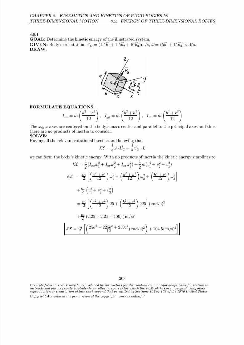
8/21/2019 Kinematics and kinetics of rigidbodies
http://slidepdf.com/reader/full/kinematics-and-kinetics-of-rigidbodies 169/190
CHAPTER 8. KINEMATICS AND KINETICS OF RIGID BODIES IN
THREE-DIMENSIONAL MOTION 8.9. ENERGY OF THREE-DIMENSIONAL BODIES
8.9.1GOAL: Determine the kinetic energy of the illustrated system.GIVEN: Body’s orientation. vG = (1.5
b1 + 1.5
b2 + 10
b3)m/s, ω = (5
b1 + 15
b3) rad/s.
DRAW:
FORMULATE EQUATIONS:
I xx = ma2 + c2
12 , I yy = m b2 + a2
12 , I zz = mb2 + c2
12 The x,y,z axes are centered on the body’s mass center and parallel to the principal axes and thusthere are no products of inertia to consider.SOLVE:Having all the relevant rotational inertias and knowing that
KE = 1
2ω · H O +
1
2vG ·
L
we can form the body’s kinetic energy. With no products of inertia the kinetic energy simplifies to
KE = 1
2(I xxω2
1 + I yy ω2
2 + I zz ω2
3) +
1
2m(v2
1 + v2
2 + v2
3)
KE = m
2 a2 + c2
12 ω21
+ b2 + a2
12 ω22
+ b2 + c2
12 ω23
+m2
v21
+ v22
+ v23
= m2
a2 + c2
12
25 +
b2 + c2
12
225
( rad/s)2
+m2 (2.25 + 2.25 + 100) ( m/s)2
KE = m2
25a2 + 225b2 + 250c2
12 ( rad/s)2
+ 104.5( m/s)2
Excerpts from this work may be reproduced by instructors for distribution on a not-for-profit basis for testing or instructional purposes only to students enrolled in courses for which the textbook has been adopted. Any other reproduction or translation of this work beyond that permitted by Sections 107 or 108 of the 1976 United States
Copyright Act without the permission of the copyright owner is unlawful.
203
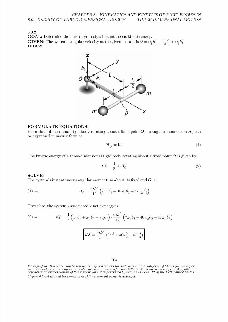
8/21/2019 Kinematics and kinetics of rigidbodies
http://slidepdf.com/reader/full/kinematics-and-kinetics-of-rigidbodies 170/190
8.9. ENERGY OF THREE-DIMENSIONAL BODIES
CHAPTER 8. KINEMATICS AND KINETICS OF RIGID BODIES IN
THREE-DIMENSIONAL MOTION
8.9.2GOAL: Determine the illustrated body’s instantaneous kinetic energy.GIVEN: The system’s angular velocity at the given instant is ω = ω1
b1 + ω2
b2 + ω3
b3.
DRAW:
FORMULATE EQUATIONS:For a three-dimensional rigid body rotating about a fixed point O , its angular momentum
H O can
be expressed in matrix form as
HO
= Iω (1)
The kinetic energy of a three-dimensional rigid body rotating about a fixed point O is given by
KE =
1
2
ω·
H O (2)
SOLVE:The system’s instantaneous angular momentum about its fixed end O is
(1) ⇒ H O =
mL2
12
7ω1
b1 + 40ω2
b2 + 47ω3
b3
Therefore, the system’s associated kinetic energy is
(2) ⇒ KE = 1
2
ω1
b1 + ω2
b2 + ω3
b3
· mL2
12
7ω1
b1 + 40ω2
b2 + 47ω3
b3
KE = mL2
24
7ω2
1 + 40ω2
2 + 47ω2
3
Excerpts from this work may be reproduced by instructors for distribution on a not-for-profit basis for testing or instructional purposes only to students enrolled in courses for which the textbook has been adopted. Any other reproduction or translation of this work beyond that permitted by Sections 107 or 108 of the 1976 United States
Copyright Act without the permission of the copyright owner is unlawful.
204

8/21/2019 Kinematics and kinetics of rigidbodies
http://slidepdf.com/reader/full/kinematics-and-kinetics-of-rigidbodies 171/190
CHAPTER 8. KINEMATICS AND KINETICS OF RIGID BODIES IN
THREE-DIMENSIONAL MOTION 8.9. ENERGY OF THREE-DIMENSIONAL BODIES
8.9.3GOAL: Determine the kinetic energy of the illustrated system and compare how the energy changesfor finite vs infinitesimal width.GIVEN: Body’s orientation. ω = (20ı − 10 ) rad/s, a = 0.5 m, b = 0.4 m, h = 0.02m or 0.DRAW:
FORMULATE EQUATIONS: From Appendix B we have:
I xx
= m
b2 + h2
12
, I
yy = m
a2 + b2
12
, I
zz = m
a2 + h2
12
To find the mass moments of inertia and products of inertia we use (8.24)-(8.29) with r1 = a/2,r2 = h/2 and r3 = b/2.
I xx = I xx
+ m(r22
+ r23
)
= m
b2 + h2
12
+ m
b2 + h2
4
= m
b2 + h2
3
I yy = I yy + m(r23 + r21)
= m
a2 + b2
12
+ m
a2 + b2
4
= m
a2 + b2
3
I zz = I zz + m(r2
1 + r2
2)
= m
a2 + h2
12
+ m
a2 + h2
4
= m
a2 + h2
3
I xy = I xy + mr1r2 = m
ah
4
I yz = I yz + mr2r3 = m
bh4
I zx = I
zx + mr3r1 = m
ab
4
SOLVE:
Excerpts from this work may be reproduced by instructors for distribution on a not-for-profit basis for testing or instructional purposes only to students enrolled in courses for which the textbook has been adopted. Any other reproduction or translation of this work beyond that permitted by Sections 107 or 108 of the 1976 United States
Copyright Act without the permission of the copyright owner is unlawful.
205
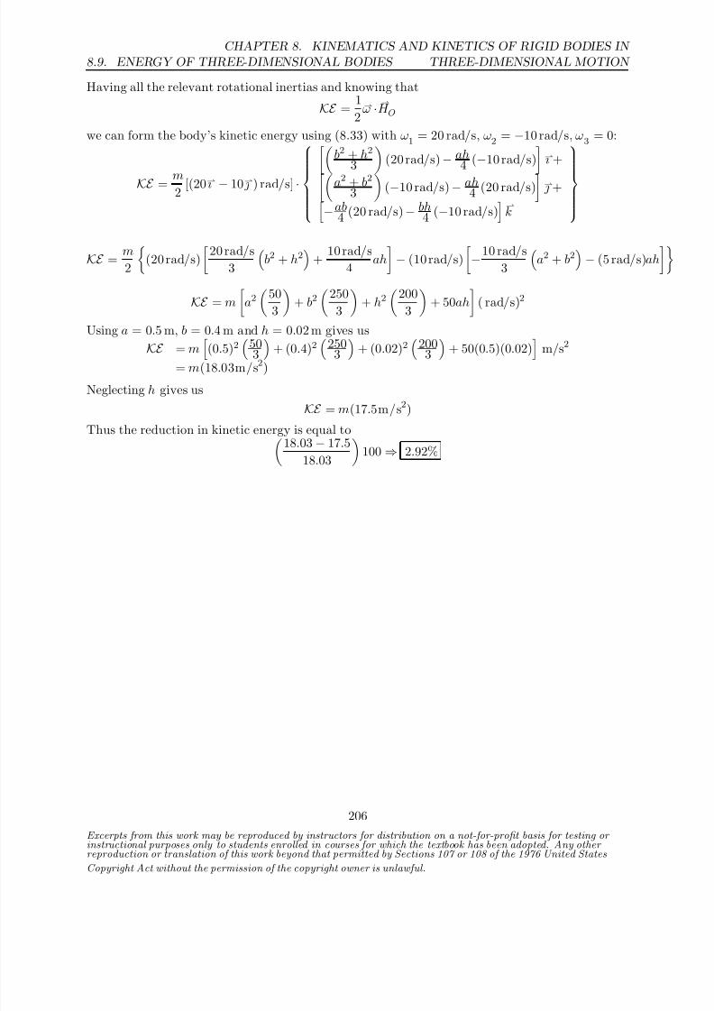
8/21/2019 Kinematics and kinetics of rigidbodies
http://slidepdf.com/reader/full/kinematics-and-kinetics-of-rigidbodies 172/190
8.9. ENERGY OF THREE-DIMENSIONAL BODIES
CHAPTER 8. KINEMATICS AND KINETICS OF RIGID BODIES IN
THREE-DIMENSIONAL MOTION
Having all the relevant rotational inertias and knowing that
KE = 1
2ω · H O
we can form the body’s kinetic energy using (8.33) with ω1 = 20 rad/s, ω2 = −10 rad/s, ω3 = 0:
KE = m2
[(20ı − 10 ) rad/s] ·
b2 + h2
3 (20 rad/s) − ah4 (−10 rad/s)
ı +a2 + b23
(−10 rad/s) − ah
4 (20 rad/s) +
−ab4 (20 rad/s) − bh
4 (−10 rad/s)k
KE = m
2
(20 rad/s)
20 rad/s
3
b2 + h2
+
10 rad/s
4 ah
− (10 rad/s)
−10 rad/s
3
a2 + b2
− (5 rad/s)ah
KE = m
a2
50
3
+ b2
250
3
+ h2
200
3
+ 50ah
( rad/s)2
Using a = 0.5 m, b = 0.4 m and h = 0.02 m gives us
KE = m (0.5)2 50
3 + (0.4)2 250
3 + (0.02)2 200
3 + 50(0.5)(0.02) m/s
2
= m(18.03m/s2)
Neglecting h gives us
KE = m(17.5m/s2)
Thus the reduction in kinetic energy is equal to18.03 − 17.5
18.03
100 ⇒ 2.92%
Excerpts from this work may be reproduced by instructors for distribution on a not-for-profit basis for testing or instructional purposes only to students enrolled in courses for which the textbook has been adopted. Any other reproduction or translation of this work beyond that permitted by Sections 107 or 108 of the 1976 United States
Copyright Act without the permission of the copyright owner is unlawful.
206

8/21/2019 Kinematics and kinetics of rigidbodies
http://slidepdf.com/reader/full/kinematics-and-kinetics-of-rigidbodies 173/190
CHAPTER 8. KINEMATICS AND KINETICS OF RIGID BODIES IN
THREE-DIMENSIONAL MOTION 8.9. ENERGY OF THREE-DIMENSIONAL BODIES
8.9.4GOAL: Determine the kinetic energy of the illustrated system.GIVEN: Body’s orientation. ω = (8ı + 6 ) rad/s, r = 0.2 m and h = 0.6 m.DRAW:
FORMULATE EQUATIONS:From Appendix B we have
I xx
= I yy
=
3m(4r2 + h2)
80
, I
zz = I
ZZ =
3mr2
10
To find the mass moments of inertia and products of inertia we use (8.24)-(8.29) with r1 = r2 = 0
and r3 = 3h4 .
I XX
= I Y Y
= I xx
+
9mh2
16
=
3m(r2 + 4h2)
20
I xy = I yz = I zx = 0
SOLVE:Having all the relevant rotational inertias and knowing that
KE = 1
2ω · H O
we can form the body’s kinetic energy using (8.33) with ω1 = 8 rad/s, ω2 = 6 rad/s, ω3 = 0:
KE = 1
2[(8ı + 6 ) rad/s] ·
3m(r2 + 4h2)20 (8 rad/s)ı
3m(r2 + 4h2)20 (6 rad/s)
KE = 3m
2 [(8ı + 6 ) rad/s] ·
(0.2 m)2 + 4(0.6 m)2
20 (8 rad/s)ı
(0.2 m)2 + 4(0.6 m)2
20 (6 rad/s)
KE = m(7.104 + 3.996)( m/s)2 = 11.1m(m/s)2
Excerpts from this work may be reproduced by instructors for distribution on a not-for-profit basis for testing or instructional purposes only to students enrolled in courses for which the textbook has been adopted. Any other reproduction or translation of this work beyond that permitted by Sections 107 or 108 of the 1976 United States
Copyright Act without the permission of the copyright owner is unlawful.
207

8/21/2019 Kinematics and kinetics of rigidbodies
http://slidepdf.com/reader/full/kinematics-and-kinetics-of-rigidbodies 174/190
8.9. ENERGY OF THREE-DIMENSIONAL BODIES
CHAPTER 8. KINEMATICS AND KINETICS OF RIGID BODIES IN
THREE-DIMENSIONAL MOTION
8.9.5GOAL: Determine the triangular plate’s kinetic energy.GIVEN: The plate spins about its fixed end O with an angular velocity of ω = ω2
b2 + ω3
b3.
DRAW:
FORMULATE EQUATIONS:For a three-dimensional rigid body rotating about a fixed point O , its angular momentum
H O can
be expressed in matrix form as
HO
= Iω (1)
The kinetic energy of a three-dimensional rigid body rotating about a fixed point O is given by
KE = 1
2ω · H O (2)
SOLVE:The plate’s angular momentum about its fixed end O is
(1) ⇒ H O =
ma2
36
−5ω2
b1 + 6ω2
b2 + 12ω3
b3
Thus, we have that the plate’s kinetic energy is given by
(2) ⇒ KE = 1
2
ω2
b2 + ω3
b3
· ma2
36
−5ω2
b1 + 6ω2
b2 + 12ω3
b3
KE = ma2
12
ω22
+ 2ω23
Excerpts from this work may be reproduced by instructors for distribution on a not-for-profit basis for testing or instructional purposes only to students enrolled in courses for which the textbook has been adopted. Any other reproduction or translation of this work beyond that permitted by Sections 107 or 108 of the 1976 United States
Copyright Act without the permission of the copyright owner is unlawful.
208
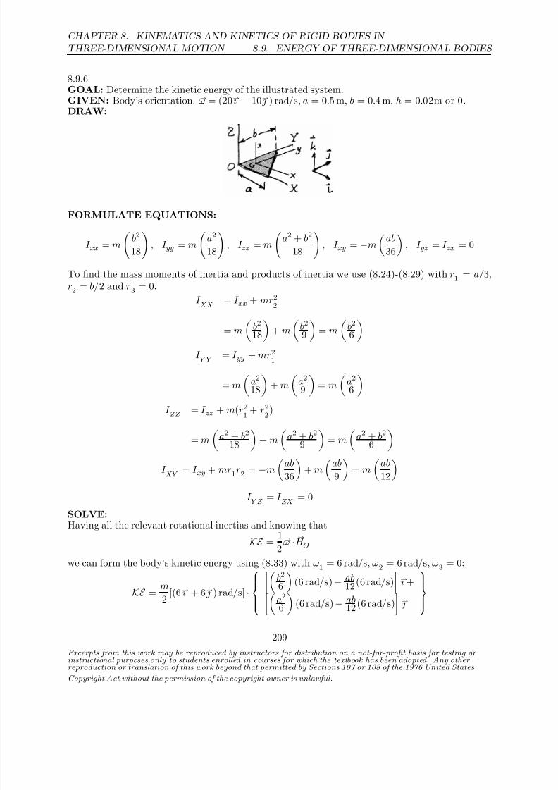
8/21/2019 Kinematics and kinetics of rigidbodies
http://slidepdf.com/reader/full/kinematics-and-kinetics-of-rigidbodies 175/190
CHAPTER 8. KINEMATICS AND KINETICS OF RIGID BODIES IN
THREE-DIMENSIONAL MOTION 8.9. ENERGY OF THREE-DIMENSIONAL BODIES
8.9.6GOAL: Determine the kinetic energy of the illustrated system.GIVEN: Body’s orientation. ω = (20ı − 10 ) rad/s, a = 0.5 m, b = 0.4 m, h = 0.02m or 0.DRAW:
FORMULATE EQUATIONS:
I xx = m
b2
18
, I yy = m
a2
18
, I zz = m
a2 + b2
18
, I xy = −m
ab
36
, I yz = I zx = 0
To find the mass moments of inertia and products of inertia we use (8.24)-(8.29) with r1 = a/3,r2 = b/2 and r3 = 0.
I XX
= I xx + mr22
= m
b2
18
+ m
b2
9
= m
b2
6
I Y Y
= I yy + mr21
= m
a2
18
+ m
a2
9
= m
a2
6
I ZZ = I zz + m(r
2
1 + r
2
2)
= m
a2 + b2
18
+ m
a2 + b2
9
= m
a2 + b2
6
I XY
= I xy + mr1r2 = −m
ab
36
+ m
ab
9
= m
ab
12
I Y Z
= I ZX
= 0
SOLVE:Having all the relevant rotational inertias and knowing that
KE =
1
2
ω
·
H O
we can form the body’s kinetic energy using (8.33) with ω1 = 6 rad/s, ω2 = 6 rad/s, ω3 = 0:
KE = m
2 [(6ı + 6 ) rad/s] ·
b2
6
(6 rad/s) − ab
12 (6 rad/s)
ı +
a26
(6 rad/s) − ab
12 (6 rad/s)
Excerpts from this work may be reproduced by instructors for distribution on a not-for-profit basis for testing or instructional purposes only to students enrolled in courses for which the textbook has been adopted. Any other reproduction or translation of this work beyond that permitted by Sections 107 or 108 of the 1976 United States
Copyright Act without the permission of the copyright owner is unlawful.
209

8/21/2019 Kinematics and kinetics of rigidbodies
http://slidepdf.com/reader/full/kinematics-and-kinetics-of-rigidbodies 176/190
8.9. ENERGY OF THREE-DIMENSIONAL BODIES
CHAPTER 8. KINEMATICS AND KINETICS OF RIGID BODIES IN
THREE-DIMENSIONAL MOTION
KE = 3m
a2 + b2 − ab
( rad/s)2
Excerpts from this work may be reproduced by instructors for distribution on a not-for-profit basis for testing or instructional purposes only to students enrolled in courses for which the textbook has been adopted. Any other reproduction or translation of this work beyond that permitted by Sections 107 or 108 of the 1976 United States
Copyright Act without the permission of the copyright owner is unlawful.
210

8/21/2019 Kinematics and kinetics of rigidbodies
http://slidepdf.com/reader/full/kinematics-and-kinetics-of-rigidbodies 177/190
CHAPTER 8. KINEMATICS AND KINETICS OF RIGID BODIES IN
THREE-DIMENSIONAL MOTION 8.9. ENERGY OF THREE-DIMENSIONAL BODIES
8.9.7GOAL: Determine the kinetic energy of the arm AB .GIVEN: Body’s orientation.DRAW:
FORMULATE EQUATIONS:Let L1 = |OA| and L2 = |AB|.From the given information of the original problem we see that ωAB =
ψb3 − θ
b2.
Using the general formula for the mass moment of inertia of a thin rod along with the parallel axistheorem gives us
I XX
= mL21
, I Y Y
=mL2
2
3 , I
ZZ =
mL22
3 + mL2
1
The only non-zero product of inertia is I XY
:
I XY
= ρ
L2
0
L1x dx =ρL1L2
2
2 =
mL1L2
2
SOLVE:Having all the relevant rotational inertias and knowing that
KE =
1
2
ω·
H O
we can form the body’s kinetic energy using (8.33) with ω1 = 0, ω2 = −θ, ω3 = ψ:
KE = 1
2[(−θ
b2 + ψ
b3)] ·
mL1L22
b1(θ)+
mL22
3 (−θ)b2+
mL2
23 + mL2
1
ψb3
KE = m L2
26 θ2 + L2
26 +L2
12 ψ2
Excerpts from this work may be reproduced by instructors for distribution on a not-for-profit basis for testing or instructional purposes only to students enrolled in courses for which the textbook has been adopted. Any other reproduction or translation of this work beyond that permitted by Sections 107 or 108 of the 1976 United States
Copyright Act without the permission of the copyright owner is unlawful.
211

8/21/2019 Kinematics and kinetics of rigidbodies
http://slidepdf.com/reader/full/kinematics-and-kinetics-of-rigidbodies 178/190
8.9. ENERGY OF THREE-DIMENSIONAL BODIES
CHAPTER 8. KINEMATICS AND KINETICS OF RIGID BODIES IN
THREE-DIMENSIONAL MOTION
8.9.8GOAL: Determine the kinetic energy of the rotating disk.GIVEN: Body’s orientation. r = 0.23m, h = 0.01m, a = 0.3 m, ω1 = 10 rad/s, ω2 = 70 rad/s,m = 1.2kg.DRAW:
FORMULATE EQUATIONS: Let the disk’s radius be denoted by r . From the given informa-tion in the original problem we see that ωAB = −ω1
+ ω2ı .
We’ll determine the kinetic energy associated with the speed of the mass center ( 12 mv2
G) and that
associated with rotation about the mass center.From Appendix B we have
I yy = I zz =m
3r2 + h2
12 , I xx =
mr2
2
All products of inertia are zero.SOLVE:
Having all the relevant rotational inertias and knowing thatKE = 1
2mv2
G +
1
2ωD ·
H G
we can form the body’s kinetic energy using (8.33) with ωD
= 70ı rad/s − 10 rad/s. Note thatfrom the definition in the original problem ω1 indicates rotational velocity about the (negative) Y axis and ω2 indicates rotational velocity about the x axis.The component of kinetic energy due to motion of the mass center is given by
KE trans
= 1
2mv2
G =
1
2m(aω1)2 =
1
2(1.2 kg)(0.3 m)2(10 rad/s)2 = 5.4 J
The rotational kinetic energy is found from
KE rot = 1
2 [(ω2ı − ω1 )] ·mr2
2 (ω2)ı +
m(3r2 + h2)12 (−ω1)
KE = KE
trans
+ KE rot
= 5.4 J + m
2
r2ω2
2
2 +
(3r2 + h2)ω21
12
Excerpts from this work may be reproduced by instructors for distribution on a not-for-profit basis for testing or instructional purposes only to students enrolled in courses for which the textbook has been adopted. Any other reproduction or translation of this work beyond that permitted by Sections 107 or 108 of the 1976 United States
Copyright Act without the permission of the copyright owner is unlawful.
212

8/21/2019 Kinematics and kinetics of rigidbodies
http://slidepdf.com/reader/full/kinematics-and-kinetics-of-rigidbodies 179/190
CHAPTER 8. KINEMATICS AND KINETICS OF RIGID BODIES IN
THREE-DIMENSIONAL MOTION 8.9. ENERGY OF THREE-DIMENSIONAL BODIES
KE = 5.4 J + 1.2 kg
2
(0.23m)2(70 rad/s)2
2 +
(3(0.23m)2 + (0.01m)2)(10 rad/s)2
12
= 84.0 J
Excerpts from this work may be reproduced by instructors for distribution on a not-for-profit basis for testing or instructional purposes only to students enrolled in courses for which the textbook has been adopted. Any other reproduction or translation of this work beyond that permitted by Sections 107 or 108 of the 1976 United States
Copyright Act without the permission of the copyright owner is unlawful.
213

8/21/2019 Kinematics and kinetics of rigidbodies
http://slidepdf.com/reader/full/kinematics-and-kinetics-of-rigidbodies 180/190
8.9. ENERGY OF THREE-DIMENSIONAL BODIES
CHAPTER 8. KINEMATICS AND KINETICS OF RIGID BODIES IN
THREE-DIMENSIONAL MOTION
8.9.9GOAL: Determine the kinetic energy of the rotating system.GIVEN: Body’s orientation. r = 0.004m, h = 0.1 m.DRAW:
FORMULATE EQUATIONS: From the given information in the original problem we see that
ωA = ω1
b1 + ω2
b2 = (−50
b1 + 2
b2) rad/s.We’ll consider three components of the kinetic energy of the system: the rotational energy of the3-arm body about O, the translational kinetic energy of the mass center of each wheel and therotational energy of each wheel about its mass center.Approximating the arms as thin rods lets us calculate the mass moment of inertia of the 3-armbody about the Y axis:
I 3−a = 3
m3−ah2
3
= m3−ah2
Approximating the wheels as thin disks we have, from Appendix B:
I zz = I yy = mr2
4 , I xx =
mr2
2
All products of inertia are zero.SOLVE:Having all the relevant rotational inertias and knowing that
KE = 1
2I 3−aω2
2 +
1
2mv2
G +
1
2ωw ·
H G
we can form the body’s kinetic energy using (8.33) with ωw = −50b1 rad/s + 2
b2 rad/s.
The kinetic energy due to rotation of the 3-arm body is given by
KE 3−a
= 1
2I 3−aω2
2 =
1
2(0.005 kg)(0.1 m)2(2 rad/s)2 = 1.0×10⁻⁴ J
The component of kinetic energy due to motion of the mass center of the wheels is given by
KE trans= 3
1
2mwh2ω2
2 = 1.5(0.002 kg)(0.1 m)2(2 rad/s)2 = 1.2
×10−4 J
Finally, the rotational kinetic energy of the wheels is found from
KE rot
= 31
2[(ω1
b1 + ω2
b2)] ·
mr22 ω1
b1+
mr2
4 ω2
b2
Excerpts from this work may be reproduced by instructors for distribution on a not-for-profit basis for testing or instructional purposes only to students enrolled in courses for which the textbook has been adopted. Any other reproduction or translation of this work beyond that permitted by Sections 107 or 108 of the 1976 United States
Copyright Act without the permission of the copyright owner is unlawful.
214

8/21/2019 Kinematics and kinetics of rigidbodies
http://slidepdf.com/reader/full/kinematics-and-kinetics-of-rigidbodies 181/190
CHAPTER 8. KINEMATICS AND KINETICS OF RIGID BODIES IN
THREE-DIMENSIONAL MOTION 8.9. ENERGY OF THREE-DIMENSIONAL BODIES
KE rot
= 3m2
r2ω2
12 +
r2ω22
4
= 3(0.002) kg
2
(0.004m)2(−50 rad/s)2
2 + (0.004m)2(2 rad/s)2
4
= 6.00×10⁻⁵ J
Summing the three components gives us
KE = 1.0×10⁻⁴ J + 1.2×10⁻⁴ J + 6.00×10⁻⁵ J = 2.8×10⁻⁴ J
Excerpts from this work may be reproduced by instructors for distribution on a not-for-profit basis for testing or instructional purposes only to students enrolled in courses for which the textbook has been adopted. Any other reproduction or translation of this work beyond that permitted by Sections 107 or 108 of the 1976 United States
Copyright Act without the permission of the copyright owner is unlawful.
215

8/21/2019 Kinematics and kinetics of rigidbodies
http://slidepdf.com/reader/full/kinematics-and-kinetics-of-rigidbodies 182/190
8.9. ENERGY OF THREE-DIMENSIONAL BODIES
CHAPTER 8. KINEMATICS AND KINETICS OF RIGID BODIES IN
THREE-DIMENSIONAL MOTION
8.9.10GOAL: Determine the kinetic energy of a rolling cone.GIVEN: Body’s orientation and dimensions. m = 22g.DRAW:
FORMULATE EQUATIONS: First we need to determine the cone’s angular velocity. Example8.4 shows how to determine the angular velocities of a rotating disk on the end of a bent shaft. Ourrolling cone can be thought of as precisely the same problem. The motion of OA will be the sameas that of Example 8.4’s shaft. From geometry we have β = sin−1(0.25) = 14.48. r = |AB| = 1 in
and h = |OA| = √ 42 − 12 in = 3.873inThe cone takes 2 s to complete one full rotation around the floor and thus we have
ωOA
= 2π
2 s = π rad/s
The correspondence between our problem and that of Example 8.4 isωcone → ω
W ωAO
→ ωS
3.873in → L11 in → L2
Substituting these values into the expression for ωW
gives us
ωcone = (π rad/s)sin β − 3.873cos β + sin β
1
c1 + (π rad/s) cos β
c3= (−11.78c1 + 3.042c3) rad/s
From Appendix B we have
(Note that these axes do not directly correspond to the ones in our problem). For this figure wehave
I xx
= I yy
= m(9r2 + 2h2)
36 , I
zz = I
ZZ =
mr2
2
For our problem m = 22g, r = 1 in = 0.0254m and h = 3.87in = 0.0984m.
Excerpts from this work may be reproduced by instructors for distribution on a not-for-profit basis for testing or instructional purposes only to students enrolled in courses for which the textbook has been adopted. Any other reproduction or translation of this work beyond that permitted by Sections 107 or 108 of the 1976 United States
Copyright Act without the permission of the copyright owner is unlawful.
216

8/21/2019 Kinematics and kinetics of rigidbodies
http://slidepdf.com/reader/full/kinematics-and-kinetics-of-rigidbodies 183/190
CHAPTER 8. KINEMATICS AND KINETICS OF RIGID BODIES IN
THREE-DIMENSIONAL MOTION 8.9. ENERGY OF THREE-DIMENSIONAL BODIES
To find the mass moments of inertia and products of inertia we use (8.24)-(8.29) with r2 = r3 = 0
and r1 = 2h3 .
I Y Y
= I ZZ
= I yy +
4mh2
9 =
m(r2 + 2h2)
4
I XY
= I Y Z
= I ZX
= 0
SOLVE:Having all the relevant rotational inertias and knowing that
KE = 1
2ω · H O
we can form the body’s kinetic energy using (8.33) with ω1 = −11.8 rad/s, ω2 = 0, ω3 = 3.04 rad/s:
KE = 1
2[(−11.78c1 + 3.042c3) rad/s] ·
mr2
2 (−11.78 rad/s)c1
m(r2 + 2h2)4 (3.042 rad/s)c3
KE = (0.022kg)
2 [(−11.78c1 + 3.042c3) rad/s] ·
(0.0254 m)22 (−11.78 rad/s)c1
(0.0254 m)2 + 2(0.0984 m)2
4 (3.042 rad/s)c3
KE = 1.00×10⁻³ J
Excerpts from this work may be reproduced by instructors for distribution on a not-for-profit basis for testing or instructional purposes only to students enrolled in courses for which the textbook has been adopted. Any other reproduction or translation of this work beyond that permitted by Sections 107 or 108 of the 1976 United States
Copyright Act without the permission of the copyright owner is unlawful.
217

8/21/2019 Kinematics and kinetics of rigidbodies
http://slidepdf.com/reader/full/kinematics-and-kinetics-of-rigidbodies 184/190
8.9. ENERGY OF THREE-DIMENSIONAL BODIES
CHAPTER 8. KINEMATICS AND KINETICS OF RIGID BODIES IN
THREE-DIMENSIONAL MOTION
8.9.11GOAL: Determine the angular momentum of the illustrated body about the fixed point O .GIVEN: The body rotates about the Y -axis with angular speed ω, and has areal density ρ.DRAW:
FORMULATE EQUATIONS: Let x,y,z be a set of body-fixed axes with origin O. At theinstant illustrated, these axes are aligned with the ground-fixed X,Y,Z axes. The body rotatesabout the Z -axis with angular speed ω; thus the z and Z axes remain aligned and the angularvelocity may be expressed as: ω = ω . The angular momentum of the body about point O isthen:
H O = I O
ω =
I XX −I XY −I XZ
−I Y X I Y Y −I Y Z
−I ZX −I ZY I ZZ
0
ω0
= −I
XY ω ı + I
Y Y ω − I
Y Z ω k (1)
Once we have determined the relevant inertia values about the point O, we may substitute andsolve for the angular momentum.
SOLVE: We only need to determine I XY
, I Y Y
and I Y Z
. I Y Y
is easily found as the mass momentof inertia about the Y axis is simply that of two thin rods, with masses ρab, ρac and lengths b, c,respectively, rotated about their ends:
I Y Y
= (ρac)c2
3
+ (ρab)b2
3
= ρa(b3 + c3)
3Using the appropriate equations from (8.21)-(8.29) lets us determine the products of inertia. Eachrectangle has no product of inertia when evaluated about its mass center and thus the only finiteproducts of inertia come about because we’re shifting our attention from each plate’s mass centerto the point O.
I XY
= ρ(ab)a
2
−b
2
= −ρa2b2
4
I Y Z
= ρ(ac)a
2
c
2 =
ρa2c2
4
Using these inertia values gives us
H O = ab2
4
ı +
b3 + c3
3
− ac2
4 ρaω
The kinetic energy is found from
KE = 1
2ω · H O =
1
2ω ·
b3 + c3
3
ρaω =
b3 + c3
6
ρaω2
Excerpts from this work may be reproduced by instructors for distribution on a not-for-profit basis for testing or instructional purposes only to students enrolled in courses for which the textbook has been adopted. Any other reproduction or translation of this work beyond that permitted by Sections 107 or 108 of the 1976 United States
Copyright Act without the permission of the copyright owner is unlawful.
218

8/21/2019 Kinematics and kinetics of rigidbodies
http://slidepdf.com/reader/full/kinematics-and-kinetics-of-rigidbodies 185/190
CHAPTER 8. KINEMATICS AND KINETICS OF RIGID BODIES IN
THREE-DIMENSIONAL MOTION 8.9. ENERGY OF THREE-DIMENSIONAL BODIES
8.9.12GOAL: Determine the kinetic energy of the illustrated rectangular body about the fixed point O .GIVEN: The body rotates about the Z -axis with angular speed ω , and has mass m.DRAW:
FORMULATE EQUATIONS: Let x,y,z be a set of body-fixed axes with origin O. At theinstant illustrated, these axes are aligned with the ground-fixed X,Y,Z axes. The body rotatesabout the Z -axis with angular speed ω; thus the z and Z axes remain aligned and the angular
velocity may be expressed as:
ω = ω
k . The angular momentum of the body about point O isthen:
H O = I O
ω =
I xx −I xy −I xz
−I yx I yy −I yz−I zx −I zy I zz
0
0ω
= −I xzω ı − I yz ω + I zz ω
k (1)
Once we have determined the relevant inertia values about the point O, we may substitute andsolve for the angular momentum.
SOLVE: The products of inertia about parallel axes through the center of mass G are all zero, dueto the symmetry of the body. The products of inertia about the point O may be computed fromthe parallel axis expressions for inertia.
I xz : I xz = I xz
+ mr1r3 = 0 + m
a
2− b
2 = −1
4mab
I yz : I yz = I yz + mr2r3 = 0 + m
c
2
− b
2
= −1
4mcb
The moment of inertia about the z-axis through the mass center is: I zz
= 112m
a2 + c2
. Using
the parallel axis expressions for inertia again, we obtain:
I zz :I zz = I
zz + m
r21
+ r22
=
1
12m
a2 + c2
+ m
a
2
2
+
c
2
2
= 1
3m
a2 + c2
Substituting into (1),
H O = mω1
4 ab ı +
1
4 cb +
1
3
a2 + c2
k
The kinetic energy is found from
KE = 1
2ω · H O =
1
2ωk · a2 + c2
3 mω
k = a2 + c2
6 mω2
Excerpts from this work may be reproduced by instructors for distribution on a not-for-profit basis for testing or instructional purposes only to students enrolled in courses for which the textbook has been adopted. Any other reproduction or translation of this work beyond that permitted by Sections 107 or 108 of the 1976 United States
Copyright Act without the permission of the copyright owner is unlawful.
219

8/21/2019 Kinematics and kinetics of rigidbodies
http://slidepdf.com/reader/full/kinematics-and-kinetics-of-rigidbodies 186/190
8.9. ENERGY OF THREE-DIMENSIONAL BODIES
CHAPTER 8. KINEMATICS AND KINETICS OF RIGID BODIES IN
THREE-DIMENSIONAL MOTION
8.9.13GOAL: Determine the kinetic energy of the illustrated system.GIVEN: Body’s orientation. ω = ω
k .
DRAW:
FORMULATE EQUATIONS:For our problem we’ll find the moments of inertia for two solid cylinders, one of radius r1 and oneof radius r2 . By subtracting we’ll obtain the inertias for the ring. The mass of the ring is given by
m = πhρ(R22 − R2
1)
Outer radius cylinder:
oI xx
= oI zz
=πR2
2hρ(3R2
2 + h2)
12
oI yy =
πR22
hρR22
2 =
πhρR42
2
Inner radius cylinder:
iI xx =
iI zz = πR
21hρ(3R
21 + h
2
)12
iI yy =
πR21
hρR21
2 =
πhρR41
2
We now subtract the inertias of the smaller cylinder from the inertias of the larger one.
I xx
= I zz
=π hρ
3
R42 − R4
1
+ h2
R2
2 − R2
1
12
=m
h2 + 3
R21
+ R22
12
I yy = I
Y Y =
π hρ
R22 − R2
1
R21
+ R22
2
=m
R21
+ R22
2
Using the parallel axis theorem to find I XX and I ZZ we obtain
I XX
= I ZZ
=m
h2 + 3
R21
+ R22
12
+ m
h
2
2
= mh2
3 +
m(R21
+ R22
)
4
The products of inertia about X , Y , Z are zero from symmetry.The general expression for angular momentum (using ω = ω
k ) is therefore
Excerpts from this work may be reproduced by instructors for distribution on a not-for-profit basis for testing or instructional purposes only to students enrolled in courses for which the textbook has been adopted. Any other reproduction or translation of this work beyond that permitted by Sections 107 or 108 of the 1976 United States
Copyright Act without the permission of the copyright owner is unlawful.
220

8/21/2019 Kinematics and kinetics of rigidbodies
http://slidepdf.com/reader/full/kinematics-and-kinetics-of-rigidbodies 187/190
CHAPTER 8. KINEMATICS AND KINETICS OF RIGID BODIES IN
THREE-DIMENSIONAL MOTION 8.9. ENERGY OF THREE-DIMENSIONAL BODIES
H O =
mh2
3 +
m(R21
+ R22
)
4
ωk
SOLVE:Having the relevant rotational inertia and knowing that
KE =
1
2
ω
·
H O
we can form the body’s kinetic energy using (8.33):
KE = 1
2[ω
k ] ·
mh2
3 +
m(R21
+ R22
)
4
ωk
KE =
mh2
6 +m(R2
1 + R2
2)
8
ω2
Excerpts from this work may be reproduced by instructors for distribution on a not-for-profit basis for testing or instructional purposes only to students enrolled in courses for which the textbook has been adopted. Any other reproduction or translation of this work beyond that permitted by Sections 107 or 108 of the 1976 United States
Copyright Act without the permission of the copyright owner is unlawful.
221
8/21/2019 Kinematics and kinetics of rigidbodies
http://slidepdf.com/reader/full/kinematics-and-kinetics-of-rigidbodies 188/190
8.9. ENERGY OF THREE-DIMENSIONAL BODIES
CHAPTER 8. KINEMATICS AND KINETICS OF RIGID BODIES IN
THREE-DIMENSIONAL MOTION
SYSTEM ANALYSIS: Chapter 8
Excerpts from this work may be reproduced by instructors for distribution on a not-for-profit basis for testing or instructional purposes only to students enrolled in courses for which the textbook has been adopted. Any other reproduction or translation of this work beyond that permitted by Sections 107 or 108 of the 1976 United States
Copyright Act without the permission of the copyright owner is unlawful.
222
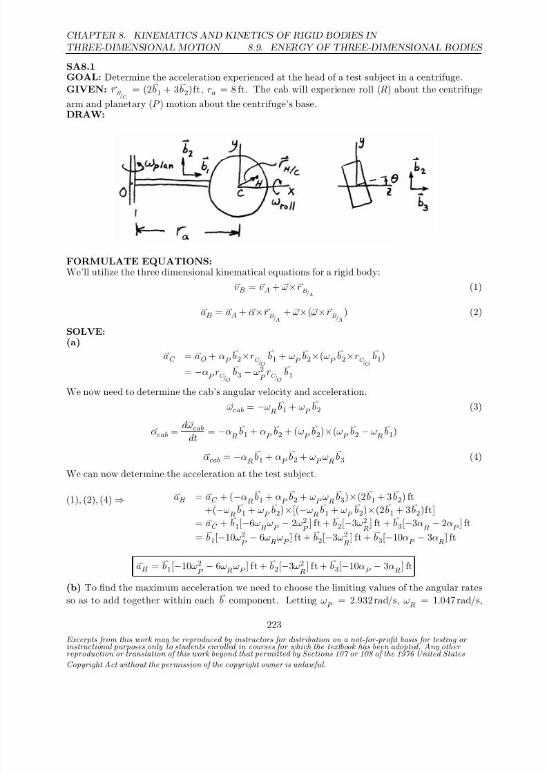
8/21/2019 Kinematics and kinetics of rigidbodies
http://slidepdf.com/reader/full/kinematics-and-kinetics-of-rigidbodies 189/190
CHAPTER 8. KINEMATICS AND KINETICS OF RIGID BODIES IN
THREE-DIMENSIONAL MOTION 8.9. ENERGY OF THREE-DIMENSIONAL BODIES
SA8.1GOAL: Determine the acceleration experienced at the head of a test subject in a centrifuge.GIVEN: r
H /C
= (2b1 + 3
b2)ft, ra = 8 ft. The cab will experience roll (R) about the centrifuge
arm and planetary (P ) motion about the centrifuge’s base.DRAW:
FORMULATE EQUATIONS:
We’ll utilize the three dimensional kinematical equations for a rigid body:vB = vA + ω×rB/A
(1)
aB = aA + α×rB/A+ ω×(ω×rB/A
) (2)
SOLVE:(a)
aC = aO + αP
b2×rC /O
b1 + ω
P
b2×(ω
P
b2×rC /O
b1)
= −αP
rC /O
b3 − ω2
P rC /O
b1
We now need to determine the cab’s angular velocity and acceleration.
ωcab = −ωR
b1 + ωP
b2 (3)
αcab = dωcab
dt = −α
R
b1 + α
P
b2 + (ω
P
b2)×(ω
P
b2 − ω
R
b1)
αcab = −αR
b1 + α
P
b2 + ω
P ωR
b3 (4)
We can now determine the acceleration at the test subject.
(1), (2), (4) ⇒ aH = aC + (−αR
b1 + α
P
b2 + ω
P ωR
b3)×(2
b1 + 3
b2) ft
+(−ωR
b1 + ω
P
b2)×[(−ω
R
b1 + ω
P
b2)×(2
b1 + 3
b2)ft]
= aC + b1[−6ω
RωP − 2ω2
P ] ft +
b2[−3ω2
R] ft +
b3[−3α
R − 2α
P ] ft
=
b1[−10ω
2
P − 6ωRωP ] ft +
b2[−3ω
2
R ] ft +
b3[−10αP − 3αR ] ft
aH = b1[−10ω2
P − 6ω
RωP
] ft + b2[−3ω2
R] ft +
b3[−10α
P − 3α
R] ft
(b) To find the maximum acceleration we need to choose the limiting values of the angular rates
so as to add together within each b component. Letting ω
P = 2.932 rad/s, ω
R = 1.047 rad/s,
Excerpts from this work may be reproduced by instructors for distribution on a not-for-profit basis for testing or instructional purposes only to students enrolled in courses for which the textbook has been adopted. Any other reproduction or translation of this work beyond that permitted by Sections 107 or 108 of the 1976 United States
Copyright Act without the permission of the copyright owner is unlawful.
223

8/21/2019 Kinematics and kinetics of rigidbodies
http://slidepdf.com/reader/full/kinematics-and-kinetics-of-rigidbodies 190/190
8.9. ENERGY OF THREE-DIMENSIONAL BODIES
CHAPTER 8. KINEMATICS AND KINETICS OF RIGID BODIES IN
THREE-DIMENSIONAL MOTION
αP
= 0.2618 rad/s2, αR
= 1.745 rad/s2
gives us a solution of
|aH
| = 105ft/s2 = 3.3g