kinetics industries inc. industries inc. 140 stokes avenue phone: 609-883-9700 trenton, nj 08638...
TRANSCRIPT

Kinetics Industries Inc. 140 Stokes Avenue Phone: 609-883-9700 Trenton, NJ 08638 Fax: 609-883-0025
email: [email protected]
Operation and Maintenance Manual For
Kinetics Models: KSR6C007PM11O Output: 7.5 KW, 125 VDC, 60 amps DC Input: 103VAC, 3 phase, 60 Hz, 9.4 KVA, 52.7 Amps KSR6F017PM11O Output: 17 KW, 125 VDC, 136 amps DC Input: 103VAC, 3 phase, 60 Hz, 21.25 KVA, 110 Amps
KSR6C015PM22O Output: 15 KW, 250 VDC, 60 amps DC Input: 205VAC, 3 phase, 60 Hz, 8.75 KVA, 52.7 Amps
KSR6F034PM22O Output: 34 KW, 250 VDC, 136 amps DC Input: 205VAC, 3 phase, 60 Hz, 2.5 KVA, 110 Amps Exciter Regulators for Brush Type Synchronous Motors
LISTED
These regulators are designed for maximum output at 40’C ambient. When installing the regulator in an enclosure, either with other equipment or alone, adequate ventilation must be provided to prevent exceeding this operating ambient temperature.

PHONE: 609-883-9700 FAX: 609-883-0025
E-mail:[email protected] INDUSTRIES INC 140 STOKES AVENUE TRENTON, NJ 08638
1
Proprietary Information This manual has been furnished as a guide for the operation and maintenance of the product manufactured by Kinetics Industries Inc as described herein. The information is provided to owners of this equipment for this purpose and is not to be used for any other purpose. No part of this document may be reproduced or transmitted in any form or by any means, electronic or mechanical, for any purpose, without the express written permission of Kinetics Industries Inc.
STANDARD STATEMENT OF WARRANTY AND
LIMITATION OF LIABILITY Equipment manufactured by Kinetics Industries, Inc., is guaranteed for a period of one year from date of shipment against defects in materials and/or workmanship and to operate in accordance with our proposals, specifications and nameplate data under conditions of proper installation, rated load, environment and usage. Any defects in materials and/or workmanship will be repaired or replaced at our option, F.O.B. our plant or, at our option, in the field under straight time conditions. Kinetics shall in no event be responsible for special, indirect, or consequential damages, nor for repairs or replacements made by others without written authorization of Kinetics. Correction of defects by repairing or replacing shall constitute the fulfillment of Kinetics warranty. Kinetics’ liability on any claim of any kind, including negligence, for any loss or damage arising out of, connected with, or resulting from the sale of Kinetics’ equipment shall in no case exceed the total price paid to kinetics for such equipment. The foregoing warranty is in lieu of any other warranty or obligation, expressed or implied, and no liability is assumed by Kinetics Industries, Inc. except as is expressly stated above. It is expressly understood and agreed that Kinetics makes no warranty with respect to any equipment not manufactured by Kinetics or with respect to any components of Kinetics’ equipment manufactured by others. In all such cases, the Buyer shall rely solely on the warranty of the manufacturers of such equipment of component, if any. This document is based on information available at the time of its publication. While efforts have been made to ensure accuracy, the information contained herein does not cover all details or variations in components and programming, nor does it provide for every possible contingency in connection with installation, operation and maintenance. Features may be described herein that are not present in all physical components and logical sequence configuration. Kinetics Industries, Inc. makes no representation or warranty, expressed, implied, or statutory, with respect to, and assumes no responsibility for the accuracy, completeness, sufficiency, or usefulness of the information contained herein. This product utilizes high gain analog and digital circuitry. Operation of high power radio transmitters in the immediate vicinity may create false triggering of control circuits. Although efforts to immunize the circuitry against external RFI sources have been taken, the system is not warranteed to be totally immune.
Copyright © 2002 Kinetics Industries, Inc. All rights reserved.
Kinetics Industries Inc. 140 Stokes Avenue Phone: 609-883-9700 Trenton, NJ 08638 Fax: 609-883-0025
email: [email protected]
Table of Contents For
Kinetics KSR6 Exciter Regulator Description of KSR6 Exciter Regulator Page 4 Connections to KSR6 Exciter Regulator Page 5 Description of Operation of KSR6 Exciter Regulator Page 7 Description and Adjustments of Circuits Page 7 Trouble Shooting Guide Page 11 Bill of Materials and Recommended Renewal Parts Page 12 Drawings: Regulator Schematic Page 14 RF3E Schematic Trig3 Schematic SYNTRIG Schematic Connection Diagram with KinetSync-SR Mechanical of Exciter Regulator Panel Compliance with UL and CUL Testing Page 20
Kinetics Industries Inc. 140 Stokes Avenue Phone: 609-883-9700 Trenton, NJ 08638 Fax: 609-883-0025
email: [email protected]
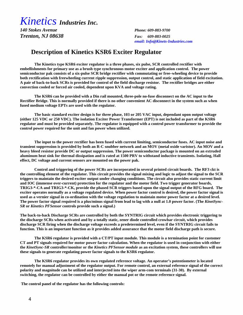
Description of Kinetics KSR6 Exciter Regulator The Kinetics type KSR6 exciter regulator is a three phases, six pulse, SCR controlled rectifier with embellishments for primary use as a brush type synchronous motor exciter and application control. The power semiconductor pak consists of a six-pulse SCR bridge rectifier with commutating or free–wheeling device to provide both rectification with freewheeling current ripple suppression, output control, and static application of field excitation. A pair of back-to-back SCRs is provided for control of the field discharge resistor. The rectifier bridges are either convection cooled or forced air cooled, dependent upon KVA and voltage rating. The KSR6 can be provided with a Din rail mounted, three-pole no-fuse disconnect on the AC input to the Rectifier Bridge. This is normally provided if there is no other convenient AC disconnect in the system such as when fused medium voltage EPTs are used with the regulator. The basic standard exciter design is for three phase, 103 or 205 VAC input, dependant upon output voltage (either 125 VDC or 250 VDC). The isolation Exciter Power Transformer (EPT) is not included as part of the KSR6 regulator and must be provided separately. The regulator is equipped with a control power transformer to provide the control power required for the unit and fan power when utilized. The input to the power rectifier has been fused with current limiting, semiconductor fuses. AC input noise and transient suppression is provided by both an R-C snubber network and an MOV (metal oxide varistor). An MOV and a heavy bleed resistor provide DC or output suppression. The power semiconductor package is mounted on an extruded aluminum heat sink for thermal dissipation and is rated at 1500 PRV to withstand inductive transients. Isolating, Hall effect, DC voltage and current sensors are mounted on the power pak. Control and triggering of the power SCRs are incorporated in several printed circuit boards. The RF3 ckt is the controlling element of the regulator. This circuit provides the signal mixing and logic to adjust the signal to the SCR triggers to maintain the desired exciter output under changing conditions. The circuit also provides static current limit and IOC (immense over-current) protection for the regulator and the motor field. Two trigger generator boards, TRIG3-*-CA and TRIG3-*-CK, provide the phased SCR triggers based upon the signal output of the RFG board. The exciter operates normally as a voltage regulated device. When power factor control is desired, the power factor signal is used as a vernier signal in co-ordination with the voltage regulation to maintain motor power factor at a desired level. The power factor signal required is a plus/minus signal from lead to lag with a null at 1.0 power factor. (The KinetSync-SR or Kinetics PFSensor controls provide such a signal.) The back-to-back Discharge SCRs are controlled by both the SYNTRIG circuit which provides electronic triggering to the discharge SCRs when activated and by a totally static, zener diode controlled crowbar circuit, which provides discharge SCR firing when the discharge voltage exceeds a predetermined level, even if the SYNTRIG circuit fails to function. This is an important function as it provides added assurance that the motor field discharge path is secure. The KSR6 regulator is provided with a CT/PT input module. This module is a termination point for customer CT and PT signals required for motor power factor calculation. When the regulator is used in conjunction with either the KinetSync-SR controller/monitor or the Kinetics PFSensor module as an excitation system, these controllers will use these signals to generate regulating power factor signals to the KSR6 regulator. The KSR6 regulator provides its own regulated reference voltage. An operator’s potentiometer is located remotely for manual adjustment of the regulator output. For remote control, an external reference signal of the correct polarity and magnitude can be utilized and interjected into the wiper arm-com terminals (31-30). By external switching, the regulator can be controlled by either the manual pot or the remote reference signal. The control panel of the regulator has the following controls:
4

Kinetics Industries Inc. 140 Stokes Avenue Phone: 609-883-9700 Trenton, NJ 08638 Fax: 609-883-0025
email: [email protected]
♦ Power Factor Set potentiometer – used to adjust sensitivity of regulator to remote power factor signal (If the regulator is used with power factor controller such as a KinetSync-SR or Kinetics PFSensor) ♦ Power Factor Regulator Enable-Disable switch (if regulator is used with power factor controller such as a
KinetSync-SR or Kinetics PFSensor) ♦ Rectifier Test Switch (Test-Run) for test operation of the rectifier from the control panel without activating
external controlling elements such as a KinetSync-SR or running the motor. ♦ Mounting position for Output Set reference pot when it is desired to be internal rather than external
Connections to Kinetics KSR6 Exciter Regulator When used with KinetSync-SR controller/monitor Input Power: Three phase power is connected to Terminals L1 and L2 at terminals provided on the input to the regulator power fuses. If a no fuse disconnect switch is provided, the input three phase connections are made to the input side of the disconnect switch which is mounted just below the power pak. Output: The exciter DC output is provided at lugs 10 (+) and 11 (-) located on the output of the power rectifier and are located at the top of the power pak. Discharge Resistor: The discharge resistor is not part of the regulator but provision has been made for connecting the discharge resistor to the regulator at lugs 11 (-) and 10D (+). These lugs are located at the top of the power pak. Control: A multi-conductor receptacle is provided for use with an umbilical multi-conductor control cable, which plugs directly onto a KinetSync-SR controller/monitor for brush-type synchronous motor control. This cable provides the necessary connections between the KinetSync-SR and the regulator for activating the regulator output at the correct time, turning off the discharge SCRs and turning on the free-wheeling SCRs, monitoring the motor field volts and amps, monitoring the power factor, protecting against field failure, pulling- out of synchronization, and failure to synchronize, annunciation of synchronization, time lock-out of re start, and trip of motor on any control failure. A second multi-conductor receptacle is provided for connection to the reference setting potentiometer and a power on indicator normally mounted on enclosure door. A Din rail mounted terminal strip is provided at the bottom of the panel for customer Start contact connection (terms 55 and 57), and customer motor controller interaction contacts including re-start timed lockout (56K terms 80and 81), remote synchronization annunciation (FAX terms 82 and 83) and field failure (FAL- form c contacts terms 84, 85,and 86) interlock with motor trip circuit. The PT/CT input module provides terminals for connecting the customer phase A-B PT connections and the phase C CT connection. (Kinetics provides aux CTs mounted on a jumper between the input CT terminals, which have less than 1 ma CT burden) The Hall effect Discharge current, Voltage and current transducers connect to the KinetSync-SR via transducer sensor cables with plug-on terminations supplied with the KinetSync-SR. When used Alone with No External Control/Monitoring:
5

Kinetics Industries Inc. 140 Stokes Avenue Phone: 609-883-9700 Trenton, NJ 08638 Fax: 609-883-0025
email: [email protected]
Input Power: Three phase power is connected to Terminals L1 and L2 at terminals provided on the input to the regulator power fuses. If a no fuse disconnect switch is provided, the input three phase connections are made to the input side of the disconnect switch which is mounted just below the power pak. Output: The exciter DC output is provided at lugs 10 (+) and 11 (-) located on the output of the power rectifier and are located at the top of the power pak. Discharge Resistor: The discharge resistor is not part of the regulator but provision has been made for connecting the discharge resistor to the regulator at lugs 11 (-) and 10D (+). These lugs are located at the top of the power pak. Control: A multi-conductor receptacle is provided for use with an umbilical multi-conductor control cable, which can go to an auxiliary control panel or other than a KinetSync-SR controller/monitor for brushless synchronous motor control. This cable would be a customized cable for whatever interfacing is necessary to the external controls. To lock off the regulator from providing SCR triggers, it is necessary to provide a shorting means for wires 43 and 44 which show on the schematic as normally closed FS contacts at the RF3 ckt. If the regulator field discharge control and the free wheeling SCRs are to be utilized a means must be utilized to activate these triggers by a dry contact for each device connected via the umbilical connection (pts 84-85 and 86-87). If no auxiliary controls are utilized, the wires can be shorted via a dummy plug on the output receptacle and the regulator can be controlled on-off manually by utilizing the regulator test switch on the regulator control panel. A second multi-conductor receptacle is provided for connection to the reference setting potentiometer and a power on indicating light normally mounted on enclosure door or the potentiometer can be mounted on the position for it on the regulator control panel. . The PT/CT input module provides terminals for connecting the customer phase A-B PT connections and the phase C CT connection. (Kinetics provides aux CTs mounted on a jumper between the input CT terminals, which have less than 1 ma CT burden). If no power factor control or protection is being utilized, there is no connection required to these terminals. If either the Kinetics PFTRP (power factor trip relay) or PFSensor (power factor transducer) are used then the PT and aux Pt signals can be obtained from the umbilical plug). When used with External Control/Monitoring: The KSR6 is adaptable for use with other controlling schemes and the interconnection between these schemes and the KSR6 can be accomplished by utilizing the connections available on either of the output receptacles and/or the DIN rail terminal strip at the bottom of the regulator panel. Input Power: Three phase power is connected to Terminals L1 and L2 at terminals provided on the input to the regulator power fuses. If a no fuse disconnect switch is provided, the input three phase connections are made to the input side of the disconnect switch which is mounted just below the power pak. Output: The exciter DC output is provided at lugs 10 (+) and 11 (-) located on the output of the power rectifier and are located at the top of the power pak.
6

Kinetics Industries Inc. 140 Stokes Avenue Phone: 609-883-9700 Trenton, NJ 08638 Fax: 609-883-0025
email: [email protected]
Discharge Resistor: The discharge resistor is not part of the regulator but provision has been made for connecting the discharge resistor to the regulator at lugs 11 (-) and 10D (+). These lugs are located at the top of the power pak. Control: A multi-conductor receptacle is provided for use with an umbilical multi-conductor control cable, which can go to an auxiliary control panel or other than a KinetSync-SR controller/monitor for brush type synchronous motor control. This cable would be a customized cable for whatever interfacing is necessary to the external controls. To lock off the regulator from providing SCR triggers, it is necessary to provide a shorting means for wires 43 and 44 which show on the schematic as normally closed FS contacts at the RF3 ckt. If the regulator field discharge control and the free wheeling SCRs are to be utilized a means must be utilized to activate these triggers by a dry contact for each device connected via the umbilical connection (pts 84-85 and 86-87). If no auxiliary controls are utilized, the wires can be shorted via a dummy plug on the output receptacle and the regulator can be controlled on-off manually by utilizing the regulator test switch on the regulator control panel. A second multi-conductor receptacle is provided for connection to the reference setting potentiometer and a power on indicating light normally mounted on enclosure door or the potentiometer can be mounted on the position for it on the regulator control panel. . The PT/CT input module provides terminals for connecting the customer phase A-B PT connections and the phase C CT connection. (Kinetics provides aux CTs mounted on a jumper between the input CT terminals, which have less than 1 ma CT burden). If no power factor control or protection is being utilized, there is no connection required to these terminals. Note: The auxiliary CTs provided on the module are selected for use with a KinetSync-SR and may or may not be suitable for alien controllers.
Description of Operation of KSR6 Regulator Power is applied to the regulator when the AC input circuit breaker is closed. The regulator is in an "OFF" condition (no SCR triggers) until the RF3 circuit is activated by opening the shorting means for wires 43 and 44 (when a relay is utilized this is the notated NC FS contacts) The KSR6 regulator is a closed loop regulator. The reference signal, set by the reference setting potentiometer, is an "ON" signal. The loop is closed on the regulator output voltage. These two signals are compared at the summing junction and the result provides the triggering to the power SCRs to turn on and control the regulator output. If power factor control is utilized the power factor signal is fed into this same junction and compared with the reference and feedback signals at the summing junction. Adjusting the amplitude of the "ON" signals correspondingly adjusts the output of the regulator. The regulator provides both static switching and regulation of the load. Disabling the SCR triggers turns off the regulator output. Description and Adjustment of RF3E-B1N02N-HS-S Regulator and Logic Circuit Control of the triggering of the power SCRs is accomplished by the RF3E-B1N02N-HS-S circuit board. The RF3E-B1N02N-HS-S circuit acts as the controlling element of the closed loop regulated exciter. This circuit provides the signal mixing and logic to adjust the SCR triggers to maintain the desired exciter output under changing conditions. The circuit also provides static current limit and IOC (immense over current) protection for the regulator and the motor field. The exciter operates normally as a voltage regulated device. When power factor control is desired, the power factor signal is used as a vernier signal in co-ordination with the voltage regulation to maintain motor power
7

Kinetics Industries Inc. 140 Stokes Avenue Phone: 609-883-9700 Trenton, NJ 08638 Fax: 609-883-0025
email: [email protected]
factor at a desired level. The power factor signal required is a plus/minus signal from lead to lag with a null at 1.0 power factor. (The KinetSync-SR or Kinetics PFSensor controls provide such a signal.) The RF3E-B1N02N-HS-S circuit has two isolated and regulated power supplies, which provide operational voltage for the circuit elements and the reference voltage for the setting potentiometer. The reference signal is interjected into the logarithmic ramp generator (pts 31(tp 6A) -30(tp22), which provides an adjustable timed rate of field change to a reference input change. The output of the ramp generator is applied to the summing junction. The feedback signal (regulator volts) is interjected into the feedback co-ord array (DC Volts (tp9)- COM (tp10) whose output is compared with the reference signal at the summing junction. If power factor regulation is desired the power factor signal is also interjected (pts 51 (tp3)- 35(tp5) into the summing junction. (the power factor signal must be a plus/minus signal with null at 1.0 power factor) The output of the summing junction is applied to the error amplifier. The output of the error amplifier is output to the Trig3 circuits (33(tp17)-32(tp4)) create the properly phased triggers for the SCRs. The amplitude of the regulator amp output sets the phasing of the SCR triggers. The current protective circuits provide current limiting and IOC by effectively either reducing the regulator output (current limit - analog reduction) or shorting the regulator amp power input (IOC - latching function with LED indication). A current signal is provided by the Hall effect sensor on the power pak. This signal is interjected into the current protective circuit (DC Amps (tp16)- COM (tp5)). Current limit - the current signal is amplified in the signal amplifier and compared against a preset reference signal. The output is then applied to the current limit comparator. If the amplified signal is greater than the current limit set point, a CL "on" is applied to the optical coupler (OTR-1), which turns on the optical transistor (OTR-1) reducing the error amplifier output. IOC - the current signal is compared against a preset reference signal. The output is then applied to the IOC comparator. If the amplified signal is greater than the reference set point, an IOC "on" is applied to the IOC delay amplifier. (this delay amplifier allows a time delay before activating IOC). After the IOC delay the IOC "on" is applied to the optical coupler (OSK1), which turns on the optical SCR (OC3) shorting the regulator amplifier power input bus and providing an IOC LED indication. The SCR is a latching device. Once activated, power must be removed from the RF3E-B1N02N-HS-S circuit for IOC reset. TRIG3 -*-CK and TRIG3 -*-CA Trigger circuits. The trigger circuits consist of individual phase trigger pulse generators, which feed optical couplers to create isolated power SCR triggers for each SCR. The trigger pulse generators are ramp and pedestal circuits to provide the SCR trigger phase control. The output of the RF3 circuit provides the pedestal, which adjusts the pulse position of the amplifier. The outputs of the trigger pulse generators are placed on isolating optical SCRs to, in turn, fire the trigger pulse amplifiers providing isolated SCR triggers of the proper phasing to control the SCR's outputs. (Longer phase delay means shorter SCR conduction time and thus lower regulator output. SYNTRIG Circuit The SYNTRIG circuit has four isolated power supplies generating four isolated SCR gates, two for the Discharge SCRs and two for the Free-wheeling SCRs. The gates can be triggered by either a closed dry contact or a static element in the 'ON' position. Normally dry contacts are provided by the KinetSync-SR (programmed close at start DST for the discharge SCRs and programmed open at stat FWT for the free-wheeling SCRs). These circuits must be activated at the proper timing for proper synchronous motor controlling.
8

Kinetics Industries Inc. 140 Stokes Avenue Phone: 609-883-9700 Trenton, NJ 08638 Fax: 609-883-0025
email: [email protected]
Adjustments: Adjust rate of reference input adjustment - adj P9 cw to slow down the ramp -Logarithmic Ramp Gen -accel Adjust maximum output of regulator - adj P3 cw to increase regulator output for a given reference input - MAX
Adjust activation point of Current Limit - adj P6 cw to increase current limit point - CUR LIM
(Standard factory setting is 125% of rated amps)
Adjust IOC set point - adj P5 cw to raise IOC operating point - IOC (Standard factory setting is 150% of rated amps) Adjust stability of regulator - adP4 cw to increase gain of signal amplifier (proportional gain) - SENS - adj P10 cw to decrease time of response (differential/integral gain) - STAB Adjustment procedures: RF3E-B1N02N-HS-S Adjusting maximum output of regulator.
• Set the Reference Setting Potentiometer to minimum • • Activate the regulator (this can be done with or without load) • Raise Reference Setting Potentiometer to maximum position. If output is not correct for the voltage input, adjust
P3 (MAX) until proper output voltage is achieved. (Standard factory adjustment is to 125 VDC with 103 VAC input and 250VDC with 205 VAC input)
Adjusting Current Limit point: To make this adjustment a load must be applied to the regulator suitable to achieve the desired current limit
point at some position below max voltage. The current limit point can be seen as the point where current caps even with an increase in the Reference
Setting Potentiometer position. • Set the Reference Setting Potentiometer to minimum • Activate the regulator • Raise Reference Setting Potentiometer until the desired current limit point is achieved
(If the current limit point is achieved before max voltage is achieved and you want to increase the activation point, simply adjust the CUR LIM adj pot until the desired point is obtained.) (If the current limit point is not achieved before max voltage is achieved and you want to increase the activation point, you will have to change the load. (If the current limit point is achieved before max voltage is achieved and you want to decrease the activation point, simply adjust the CUR LIM adj pot until the desired point is obtained.) (If the current limit point is not achieved before max voltage is achieved and you want to decrease the activation point, simply adjust the CUR LIM adj pot until the desired point is obtained.)
Adjusting IOC point: To make this adjustment a load must be applied to the regulator suitable to achieve the desired IOC point at
some position below max voltage. You will have to disable the current limit control before making this adjustment as the current limit will activate before the IOC and therefore not normally allow you to reach the IOC point. Note: to reset after IOC activation you must remove power.
NOTE: The factory IOC setting (150% rated amps) is the maximum it should be set. Raising the IOC setting above this point leaves the regulator subject to damage and any warranties will be voided.
9

Kinetics Industries Inc. 140 Stokes Avenue Phone: 609-883-9700 Trenton, NJ 08638 Fax: 609-883-0025
email: [email protected]
The IOC activation is indicated by the IOC LED illuminating • Set the Reference Setting Potentiometer to minimum • Activate the regulator • Raise the Reference Setting Potentiometer until the desired point of IOC trip is achieved
(If the IOC point is achieved before max voltage is achieved and you want to decrease the activation point, then adjust the Reference Setting Potentiometer to the desired current point and then adjust IOC until the IOC trips and the LED illuminates.) (If the current limit point is not achieved before max voltage is achieved and you want to decrease the activation point, you will have to increase loading (decrease resistance))
Adjusting regulator stability: Normally these adjustments should only be made by trained regulator personnel.
Pots P4 and P10 adjust the proportional gain and the time slope of the regulator. They are somewhat interactive and adjust the bode interactive point of the regulator. The adjustment, if required, should be made on start-up by the start-up engineer and it is not recommended that any adjustments be made by non-trained personnel.
TRIG3 -*-CK and CA Trigger circuits. There are two potentiometer adjustments on each phase channel for balancing of the trigger outputs. These adjustments have been factory set and the potentiometers sealed. They should not be field adjusted by untrained personnel. Doing so can void regulatory warranties. SYNTRIG Circuit There are no adjustments on this circuit board Notes on drawings included in this manual: The schematic and connection drawings included in this manual are for standard basic use with a KinetSync-SR controller. If the KSR6 regulator is used with other control systems or customer or system requirements make modifications to these drawings necessary they will be supplied as addendums to this manual.
10

Kinetics Industries Inc. 140 Stokes Avenue Phone: 609-883-9700 Trenton, NJ 08638 Fax: 609-883-0025
email: [email protected]
Trouble Shooting Guide Symptom: No output Possible Causes: • No line power or open circuit breaker - Restore line power or reset and close circuit breaker • Open Power Fuses (FU1-FU2-FU3) Check for load shorts - clear and replace fuses • Open control power fuse Fu21 Check for shorts, clear and replace fuses • Open control power fuse Fu10,11,12 Check for shorts, clear and replace fuses • Open heat sink thermal - Normally due to cooling fan failure or overload • No reference signal Open control fuse, shorted wiring to pot, defective Trig1 ckt • Defective Semi-conductors Check for load shorts and open power fuses then replace • Regulator not activated C heck remote control ckt and that FS contacts (NC) are activated
Symptom: Volts won't reach max Possible Causes: • Output overload and regulator is in current limit Check for shorts on output- possible motor on-shaft
electronic problems • One Power Fuse open - check all fuses, check for shorts or shorted SCR, clear and replace fuse • One phase out on input - check incoming power feed and correct • Incorrect reference signal - check reference setting pot and reference input signal • Defective Trigger ckt1 or open or shorted SCR gate - Ascertain triggers are present on SCR gate
(Are all trigger LEDs on TRIG3 ckts illuminated?) Symptom: Volts turn full on - no control
Possible Causes: • Loss of Feedback check to see that volts transducer output to RF3 is there (pts tp9-tp10) • Defective Volts transducer or open wiring - replace transducer or repair wiring Symptom: Open Power Fuses
Possible Causes: • Shorts on output • Shorted semi-conductors - some motors, when their on-shaft electronics fail, can produce high inductively coupled
transients through the exciter to the regulator. This condition is normally indicated by a shorting of the free wheeling diode. Protection for the rectifier can be helped by incorporating a VERY heavy bleed but has the problem of preloading the regulator.
Symptom: tripped IOC Possible Causes: • Shorts on output of regulator - possible failure of on-shaft motor electronics Symptom: Regulator in Current Limit
Possible Causes: • Overload
Symptom: Shorted Free Wheeling SCRs or SPdc Possible Causes:
• High discharge volts caused by open discharge path on motor start or stop - check field discharge path to be assured is functioning properly. Inspect crowbar circuit (failure should show blown components)
• Failure of discharge SCR gating - do LEDs illuminate before drive starts and turn off after field application? Possible back control circuitry or defective SYNTRIG ckt.
Symptom: Regulator turns off on thermal Possible Causes:
• Insufficient ventilation • Fan fuse or Fan failure
11
Kinetics Industries Inc. 140 Stokes Avenue Phone: 609-883-9700 Trenton, NJ 08638 Fax: 609-883-0025
email: [email protected]
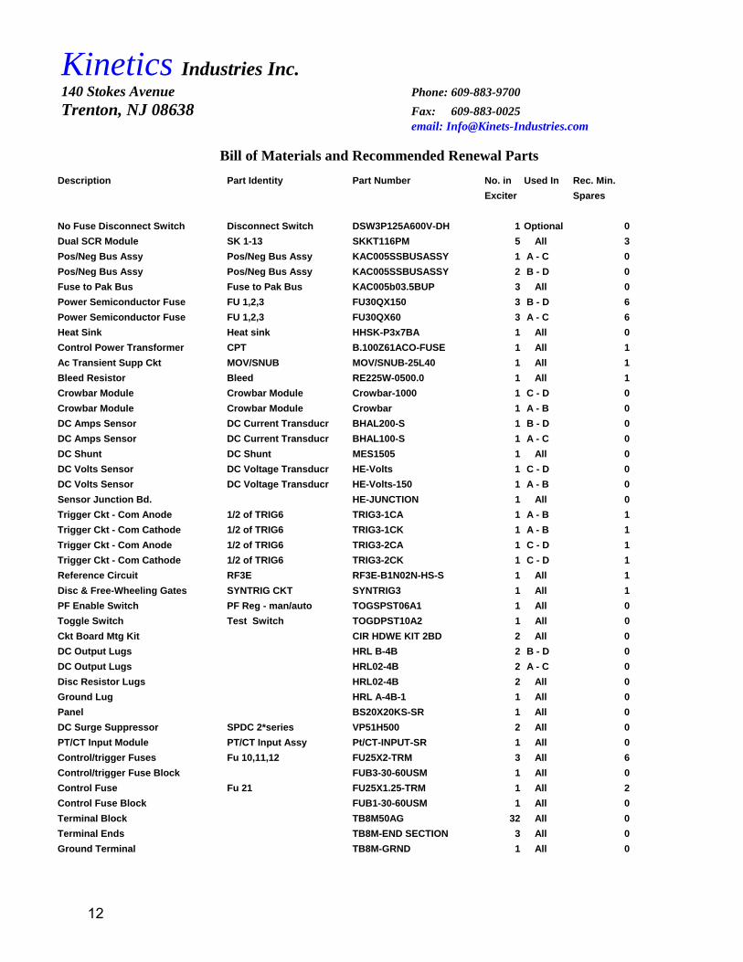
Bill of Materials and Recommended Renewal Parts
Description Part Identity Part Number No. in Used In Rec. Min. Exciter Spares
No Fuse Disconnect Switch Disconnect Switch DSW3P125A600V-DH 1 Optional 0Dual SCR Module SK 1-13 SKKT116PM 5 All 3Pos/Neg Bus Assy Pos/Neg Bus Assy KAC005SSBUSASSY 1 A - C 0Pos/Neg Bus Assy Pos/Neg Bus Assy KAC005SSBUSASSY 2 B - D 0Fuse to Pak Bus Fuse to Pak Bus KAC005b03.5BUP 3 All 0Power Semiconductor Fuse FU 1,2,3 FU30QX150 3 B - D 6Power Semiconductor Fuse FU 1,2,3 FU30QX60 3 A - C 6Heat Sink Heat sink HHSK-P3x7BA 1 All 0Control Power Transformer CPT B.100Z61ACO-FUSE 1 All 1Ac Transient Supp Ckt MOV/SNUB MOV/SNUB-25L40 1 All 1Bleed Resistor Bleed RE225W-0500.0 1 All 1Crowbar Module Crowbar Module Crowbar-1000 1 C - D 0Crowbar Module Crowbar Module Crowbar 1 A - B 0DC Amps Sensor DC Current Transducr BHAL200-S 1 B - D 0DC Amps Sensor DC Current Transducr BHAL100-S 1 A - C 0DC Shunt DC Shunt MES1505 1 All 0DC Volts Sensor DC Voltage Transducr HE-Volts 1 C - D 0DC Volts Sensor DC Voltage Transducr HE-Volts-150 1 A - B 0Sensor Junction Bd. HE-JUNCTION 1 All 0Trigger Ckt - Com Anode 1/2 of TRIG6 TRIG3-1CA 1 A - B 1Trigger Ckt - Com Cathode 1/2 of TRIG6 TRIG3-1CK 1 A - B 1Trigger Ckt - Com Anode 1/2 of TRIG6 TRIG3-2CA 1 C - D 1Trigger Ckt - Com Cathode 1/2 of TRIG6 TRIG3-2CK 1 C - D 1Reference Circuit RF3E RF3E-B1N02N-HS-S 1 All 1Disc & Free-Wheeling Gates SYNTRIG CKT SYNTRIG3 1 All 1PF Enable Switch PF Reg - man/auto TOGSPST06A1 1 All 0Toggle Switch Test Switch TOGDPST10A2 1 All 0Ckt Board Mtg Kit CIR HDWE KIT 2BD 2 All 0DC Output Lugs HRL B-4B 2 B - D 0DC Output Lugs HRL02-4B 2 A - C 0Disc Resistor Lugs HRL02-4B 2 All 0Ground Lug HRL A-4B-1 1 All 0Panel BS20X20KS-SR 1 All 0DC Surge Suppressor SPDC 2*series VP51H500 2 All 0PT/CT Input Module PT/CT Input Assy Pt/CT-INPUT-SR 1 All 0Control/trigger Fuses Fu 10,11,12 FU25X2-TRM 3 All 6Control/trigger Fuse Block FUB3-30-60USM 1 All 0Control Fuse Fu 21 FU25X1.25-TRM 1 All 2Control Fuse Block FUB1-30-60USM 1 All 0Terminal Block TB8M50AG 32 All 0Terminal Ends TB8M-END SECTION 3 All 0Ground Terminal TB8M-GRND 1 All 0
12

Kinetics Industries Inc. 140 Stokes Avenue Phone: 609-883-9700 Trenton, NJ 08638 Fax: 609-883-0025
email: [email protected]
DIN Mtd Relay R1 Relay REISO2NO/NC-1DIN 1 All 1Umbilical Receptacle-30 WHPLUGSR30 1 All 0Umbilical Receptacle-16 WHPLUGSR16 1 All 0Umbilical Cable Assy **KinetSync-SR cable WHPLUGSR30P/12FT 1 All 0Umbilical Cable Assy **KinetSync-SR cable WHPLUGSR16P/12FT 1 All 0Heat Sink Thermal Sw Heat Sink Thermal TH212NC 1 All 0Fan-Convection Booster PFA PFA 1 B - D 1Fan Guard PFA-CD551 1 B - D 0FAN Cord PFA-CD552 1 B - D 1Fan Standoffs STND2120 4 B - D 0
Description Part Identity Part Number No. in Used In Rec. Min.
Exciter Spares
Coding of ‘Used In’ Column A KSR6C07PM11O 7KW 125VDC B KSR6F17PM11O 17KW 125VDC C KSR6C15PM22O 15KW 250VDC D KSR6F34PM22O 34KW 250VDC
13

TEST SW CLOSED - RUN MODETEST SW OPEN - TEST MODE
REV: A
MFG FOR: P.O.#:
SHEET 1 OF1
KINETICS CONTROL SYSTEMS140 STOKES AVENUETRENTON, NEW JERSEY
VOLTAGE REGULATED EXCITER WITH P.F. CONTROL
DATE: DRAWN BY: SYSTEM No.:
MOVSNUB
A B CKA
9
8
K4
G4
K5
G5
K6
SK4
SK5
SK6
7SK1
K1
G1
K2
G2
K3
G3
K1
G1
K2
K3
G2
G3
SK2
SK3
5K-2W
(+)G611
33
SPdc
SK10
FROM
BLEED
CUSTOMER SYNC MOTOR FIELD
SYNTRIGCIRCUIT
*
SK11
10
10G10
G1110M G1110M
SKKT116PMSK1-SK6:
VP25L40
SHT 2 OF 2
G7
G8
10D
C
E A
G
10G8
9
8
10 -11
1110
VP51H5002*SERIES
FUSE FU1,2,3:
KinetSync-SR
1 234
Iave=116AMPSVprv=1600V
51A
B1N02N-HSHS
37
35
55
51
VOLTAGE/POWER FACTORREGULATOR
RF3E
417
10
9
11
16
22
6A
4
3
5
129
10
AC
AC
20
15
19
14
4
3
5
6
4 321
DC VOLTAGETRANSDUCER
150V=>4V
DISCHARGECURRENT
TRANSDUCER50A=>4V
DC CURRENTTRANSDUCER
200A=>4V 1 2 3
4
1 2 1 2
KINETSYNC-SR
FS
4443
35
COMDC AMPS
-15V+15V
TO KINETSYNC-SRCONTROLLERSHEET 2 OF 2
TO KINETSYNC-SRCONTROLLERSHEET 2 OF 2
COM
DISC AMPS
-15V+15V
P.F. SIGNALADJUST POT
51
5556
32
31
30
5K - 2W
CROWBARMODULE
10D
G7
G8
SK12
SK13
FUSE FU10,11,12FU25X2-TRM2A 250VAC
4
5
6FU1 FU2 FU3
8
7
9 19
18
17
OUTPUTADJUSTPOT
TO KINETSYNC-SR120 VAC TO
CPT, 100VAVpri: 104VVsec: 120V
54
FU21
FU25X1.25-TRM1.25A 250VAC
FU21
84/86
85
87
TRIG62*TRIG3 CKTs
4 5
6
-15V+15V
DC VOLTS
KINETSYNC
SHEET 2
TO
FU10
FU11
FU12
FROM KinetSync-SR
TEST SW.84
85(FWT)
TP3
32
250VAC
*
DISC RES
56
120VAC 55
56
TOSYNTRIG CKT SR
F.RABULAN05/05/05
TO SK1
TO SK2
TO SK3P.F. ANALOG SIGNAL
FROM
*
TO INTERCONNECT HALL EFFECT TRANSDUCERS TO KinetSync CONTROLLER= SHIELDED CABLES (12' EACH) SUPPLIED BY KINETICS
10D
GROUND
5617
55
45
6
56
36
(-)
GA
KBGB
KCGC
COM
DC AMPS
DISCHARGE RESISTOR:
56
56
FROM CPT
DC SHUNT150A = 50mV
S-
S+10 -11
COM
COMDC VOLTS
SKKT116PMSK10-SK13::
Iave=116AMPSVprv=1600V
X1
AC INPUT FROM EPT
X1 X1
START R1
R1
14
11
12
24
21
22
A1
A2
60
61
56
57
INTERFACE RELAY
TO KINETSYNC-SR
USED ONLY ON CONVECTION AIDED MODELS- FC
PT/CT INPUT MODULE
CTb
CTC
CTG
5:0.02AUX CT RATIO
FU-PT1
FU-PT2
VA1
VA2
FUSE: FU-PT1, PT2FU25X2-TRM
TO KinetSync-SRsheet 2
TO KinetSync-SRsheet 2
66
67
70
71
CUST 5A CT secPHASE C
CUST PT SIG120VAC
*
OPTIONAL COMPONENT
LOCATED ON REG TERMINAL STRIP
05/23/05 R SECREST
LAYER INFOKSR6F17PM110- LAYER 10 SPECIFICKSR6F34PM220- LAYER 11 SPECIFICKSR6C07PM110- LAYER 12 SPECIFICKSR6C15PM220- LAYER 13 SPECIFIC
205 VAC/3PH/60HZ FOR 250VDC REGULATORS103 VAC/3PH/60HZ FOR 125VDC REGULATORS
125VDC FOR 103 VAC INPUT250VDC FOR 205 VAC INPUT
136 ADC OUTPUT FOR CONV AIDED REGS60 ADC OUTPUT FOR CONV COOLED REGS
OUTPUTS
SEE TABLE A
THIS SCHEMATIC DRAWING IS FOR BASIC STANDARD OPERATIONWHEN THE KSR6 REGULATOR IS USED WITH A KinetSync-SR CONTROLLER.IF CUSTOMER OR SYSTEM REQUIREMENTS NECESSITATE OPERATIONAL
MODIFICATIONS, THE MODIFIED CONTROL FUNCTIONS WILL BE PROVIDED ONSEPERATE DRAWINGS ATTACHED TO THIS MANUAL.
P.F. REGULATION
*
= CUSTOMER EXTERNALCONNECTION
= LOCATED ON CUSTOMER ENCLOSURE DOOR
= INTERNAL CONTROL COMPONENT
= CONTACT FROM KinetSync-SR MODULE
= CUSTOMER INTERNAL CONNECTIONS FROM
THRU PLUG CONNECTOR-WIREHARNESS
MAN = PF DISABLE = OPEN SW.AUTO = PF ENABLE = CLOSE SW.
EXCITER PANEL TO KinetSync-SR AND ANNUNCIATIONS
*
LIGHTPOWER ON
AUTO/MAN SWITCH
CUSTOMER MOTOR START (52a)AUX. DRY CONTACT
HT SNK THERMAL
T
55
OR OTHER CONTROL
OR OTHER CONTROL
OR OTHER CONTROL
OR OTHER CONTROL
OR OTHER CONTROL
OR OTHER CONTROL
OR OTHER CONTROL
OR OTHER CONTROL
FU LGTS OPTIONAL
08/05/05
I:UL-SUBMITTALS\UL-SR\KSR6----PM--O UNIVERSAL
SEE TABLE A
OPTIONAL
NOTES:
* * *
4 5 6
7 8 9
DISCONNECT SWITCH
PFA
55120VAC
56
RECTIFIERCOOLING
FAN
MODEL: KSR6C07PM110, 7.5KW,103/3/60 TO125VDC, 52 .8AMPSMODEL: KSR6C15PM220, 15KW, 205/3/60 TO 250 VDC, 52 .8AMPSMODEL: KSR6F17PM110, 17KW, 103/3/60 TO125 VDC, 136 AMPSMODEL: KSR6F34PM220, 34KW,205/3/60 TO250 VDC, 136 AMPS
MODEL KSR6C07PM110
KSR6F17PM110
7.5151734
125
125250
250
6060
136136
KW VDC9.2518.5
103
103205
205
52.7
52.7110
110
150
150
60
602040 FC
CC
FCCCKSR6C15PM220
KSR6F34PM220
TABLE A
UNIVERSAL
COOLADC KVA VAC AAC FUSE
SEPERATE FROM REGULATOR
14

KINETICS CONTROL SYSTEMS
140 STOKES AVENUETRENTON, NEW JERSEY
DRAWN BY:DATE:
SHEET 1 OF 1
C10200 2.7+ +
1 23
+ +1
-12V
STRANDEDWIRE
21
20
+
R71.5K
R31
100
BR3
1
2 7
8
3
4 5
6
28V
28V
1
32
7
C5
60 +
OSK1
31
R11
26K
C6
.5
R13100
2.4V
D1
2.4V
Z2
OTR1 4
5
R3
Q1
C2
5SENS
P4, 1K
8
7
12V
1
2
BR1
BR2
6
12V
74
3
+12V
5 4- +
DC
11
C9C8
VR1
16
R17
R18
R19
5.1K
R205.1K
C12
C13
OA2
OA1
R21
680
4
5
R22
2.7K
ZERO
P7
5K
3
1011
69
C14
IOC
C16
.1
C17
.1
P8
ZERO
-12V
1110
639
5
4
C15
CUR LIM
+12V
+12V
-12V
R26
330
R25
75K
C18
2.7
+
C19
+
R2833K
C40
15
R27
22K
+12V
D2
1
2
OSK-1
2
1
D3
CKTNUMBER
PIN
22 PIN
NUMBER
32 1
7A 2
3
416
OTR-1
11 5
6
731
86A9
1041171251317
142215TP316301718101920211222
4
5
2W
+
+
X TP21 X TP
20
12V
VR-2
+
+
200
2
312V
2.7
XTP11
X TP16
XTP14
X TP15
SYMBOLS:
X = TEST POINT
= PIN NUMBER
= EXTERNAL COMPONENTS
= PRESSURE TERMINAL
XTP13
XTP12
T-2
T-1
-
NOTES:
ALL RESISTORS ARE 1/2 WUNLESS OTHERWIZE STATED
ALL CAPACITORS ARE IN MFDUNLESS OTHERWISE NOTED
19
18
FS
C1
R34R1
P3R5 5.1K 2W
MAX
5K 2W
BR4
R1210K
R82.2K
4
17TP17
TP4
TP5
TP3
TP1
TP6A 7A 7
100 2.2K
ACCEL STAB
R2
2.2K 5K
LO
5K
TP22
P1
5K 2W
4
Z120V
6
COM
-
+
TO TRIGGER CKT
+
FEEDBACK
INPUT
150*
*
TP3
5
INPUTREMOTE
VERNIER SIG
CONN
3
SYSTEM NO.
NOM
P6
10K
P5
5K
C11
5K
OPRS POTVOLT SET
TP9
TP10
120V
C4
P10P9
HALL SENSOR
E
5Z
13
22
RF3E-B1N02N-HSHS
KINCODE: I:\UL-KINETICS EXCITERS\SR SUBMITTAL\RF3E-B1N02N-HSHS
R6
3.33V
REFERENCE CKT RF3E-B1N02N-HSHS
SIG
COM
IOC: V => AMPS
CL: V => AMPS
FL: V => AMPS
100
1K
RK14P
9
F.RABULAN03/28/05
22
21
REMOVABLE JUMPERREMOVED WHEN USEDWITH KinetSync-SR
07/1/05
*
5.1K
10K
UNIVERSAL07/23/2006 R,. SECREST
AMP GAINS MAY BE CHANGED DUE TO CUSTOMER OR SYSTEM REQUIREMENTS
7/23/2006 MOD
3
POWER FACTOR TRIM
R91K
R24680
R23
2.2K
15

K
Q1
Q2
D1
C1.47
C2.22
R71K
C3
R2680
R168K
D2D3
P11004T
R4
R3
R8 D5
OC1
R9330
C52.7
11
12
-
+INPUT
21
22
D6
D7 D8
OC1
LED
R16470D4
C6 R121.5K
12W
R15
C75
R13330
100
R14 57K
C14 .01X
K
OUTPUT
G
K21
22
D6
D7 D8
OC1
LED
R16470
C6R121.5K 12W
R15
C75
R13330
R10
R14 57K
C14 .01X
K
OUTPUT
G
K21
22
D6
D7 D8
OC1
LED
R16470
C6R12
1.5K 12W
R15
C75
R13330
R10
R14 57K
C14 .01K
OUTPUT
G
KINETICS CONTROL SYSTEMS
140 STOKES AVENUETRENTON, NEW JERSEY
DRAWN BY:DATE: SYSTEM DWG NO.:R SECREST
X ADDED 11/87/87 rhs
L
H
0
NOTES:
TO CONNECT FOR HIGH OR LOW VOLTS AND TO INVERT TRIGGER
POLARITIES TO PROVIDE EITHER COM KATHODE OR COM ANODE TRIGGER
ALL RESISTORS ARE 1/2 WATT UNLESS OTHERWISE NOTED
COMPONENTS ARE LABLED WITH A,B,OR C SUBSCRIPTS
TRIGGER TIMING CKT TRIGGER PULSE AMPLIFIER AND FORMER
JUMPERS ARE INSTALLED ON TRANSFORMER PRIMARIES
THREE TRIGGER INPUTS ARE PARALLED TO +/- INPUT TERMINALS
B
C
A
WYE
CHANGED 1/10/90 RHS
470
R5 P5
Z120VC4
101.5
10KLO 4T
Q1
Q2
D1
C1.47
C2.22
R71K
C3
R2680
R168K
D2D3
P11004T
R4
R3
R8 D5
OC1
R9330
C5
2.7
11
12
-
+INPUT
D4
L
H
0
470
R5 P5
Z120VC4
101.5
10KLO 4T
Q1
Q2
D1
C1.47
C2.22
R71K
C3
R2680
R168K
D2D3
P11004T
R4
R3
R8 D5
OC1
R9330
C5
2.7
11
12
-
+INPUT
D4
L
H
0
470
R5 P5
Z120VC4
101.5
10KLO 4T
KINCODE G:\CKT\TRIG3
TRIG3-CA\CK-HC HI CURRENT TRIGGER CIRCUIT
REV 2/28/91 R. SECREST
R20
R20
R20
1000 35
1000 35
35
D9
D9
D9
18vac 18vac
18vac
18vac
18vac
18vac
1000
08/22/0111/15/02
SHEET 1 OF 1
470
470
470 15K 487
1.5K
680
1.5K
48715K
680
487
1.5K
680
15K
R10
100
100
X
UNIVERSAL
50v
50v
100v
100v
100v
50v
35v
R11
50v
50v
100v
100v
100v
50v
35v
R11
50v
50v
100v
100v
100v
50v
35v
R11
16

V-
COM
.1
INPUT 1
+
10K
1
2
V+
V+
10K
V-
COM
.1
INPUT 1
+
10K
1
2
V+
V+
10K
10K
51K
51K
npn+
1
2
1
2
1
2
200UF
npn+
V-
.1
INPUT 1
+
10K
V+
+
TRIG6 INPUT
ADJ TO FIRE AT.6 VOLT
10K
51K
2.2K
680
npn
470K
1.5K
LED
+npn
X2
R310K
-
C1 R9 R11
R7
R5
U11
1213
TP1
BR1
R15 R16
C3Z1
Z2
TP4
R410K
P210K
R851K
U1
C2 R10 R12
7
6
410
9
D2
R14
BR1A
BR1B
R16C
C3CZ3C
U3
D3C
R17C
R18C
R20C
D4C
2.2K
BR1C
R6
D1
750
TP2
200UF
PIN 14
100 2W 100 2W
TP3
TP5
12V
12V
-9.5V/+11.5
1
23
4 5
67
8
PIN 15
OTR-4
U2
10
9
-9.5V\+11.5V
U2
14 13
16 15 A
A
12V
OTR-5
A
V+
200UF
V-
R15C50 12W
2.2K
680
npn
470K
1.5K
LED
+npn
U3
2.2K
200UF
12V
A50 12W
DC3D
OTR-8
1
2
1
2
1
2
1
2
1
2
1
23
4 5
67
8
120/
240
V C
ON
N
T1 T2 T3PRIMARY
T1 T2 T3PRIMARY
SEC T1
SEC T1
SEC T2
SEC T2
28V
SEC T3
24V
R15DR16D
C3DBR1DZ3D
R17D
R18D
R20D
OTR-5
OTR-6
OTR-7
OTR-8
U3
10 9
D4D
Q1D
R19D
PIN 10
PIN 9
1516
120
120
240
1
222
11
444
3 3 328V
PIN 19,20
npn
+
npn
14
13
OTR-6
U3
-SOLDER PADS
+
NPN DISC TRIGON
SU2OTR-3
12
11
+
NPN FW TRIGON
OTR-7U3
11
12
04/16/02
2
4
NP
NN
PN
NOTES:1. AT THE OUTPUT OF OTR (POINT A) APROX. -0.1-0.2/+3.5V2. AT THE OUTPUT TO THE SCR 0.5+4.5V WITHOUT LOAD
SHEET 1 OF 1
KINETICS CONTROL SYSTEMS
140 STOKES AVENUETRENTON, NEW JERSEY
SYSTEMDRAWN BYDATE
SYNCHAPP TRIGGERING CIRCUITS
F.RABULAN
P1P1
TRIG6 INPUT
ADJ TO FIRE AT.6 VOLT
NOM 20V REF PWR
750
2.2K
680 470K
1.5K 2N6016
LED
OTR-1
OTR-2
OTR-3
OTR-4
2.2K
470K
1.5K 2N6016
LED
2N6016
G
K
TO FW SCR 10
25 OHM
25 OHM
25 OHM
GD1
KD1
GD2
KD2
TO DISC SCR1
TO DISC SCR2
R13
U2
R16A
U2
R18A
R19A
Q1A
C3A Z3AR17A
D3A
R20A
D4ATP10
TP11
R15BR16B R18B
R19B
Q1B
C3B Z3BR17B680
D3B
R20B
D4BTP12
TP13
R19C
Q1CR15A
200UF
PIN 21,22
12V
12V
0TR-2
OTR-1
PIN 6
PIN 5
<+>
<->
<+>
<->
PIN 4
PIN 3
PIN 2
PIN 1
<+>
<->
50 12W
5W
50 12W
5W
5W
2N6016
G
K
TO FW SCR 11
25 OHM
<+>
<->
5W
07/13/04 A.FELDMAN
SYNTRIG3
07/15/04
KINCODE: I:\UL-KINETICS EXCITERS\SR SUBMITTAL\SYNTRIG-2-7-23-2006
UNIVERSAL
17

G R
OK FAULT
P.F FLD AMPS FLD VOLTS
MOTOR STATUS
I/O STATUS
*.** **.* ***
LCD SCREEN
SCROLL MENU
FWD
BACK
ACKRESET
ENTER
ADJ VALUE
VALUEDEC
INC
MONITOR & CONTROLLER
KinetSync-SRBRUSH TYPE SYNCHRONOUS MOTOR
OUTPUT INTPUT
TO INTERCONNECT HALL EFFECT TRANSDUCERS= SHIELDED CABLES (12' EACH) SUPPLIED BY KINETICS
RS232 PORT
FALRFA
XR
56K
R
OPTIONALANALOG &DIGITALOUTPUTS
1513119753
OPTIONALANALOG & DIGITAL OUTPUTS
INTERFACE MODULE
1
161412108642
SEPARATE COMPONENTS
UNIVERSAL07/23/2006 R. SECREST
(OPTIONAL)
OPTIONAL OUTPUT INTERFACE SUB-PANEL
PT/CT INPUT MODULE
FU FUPT PT
1 2
FU FU11 12 21
FU
VA1
67
VA2
10
55
4 5 6 54
191817
CR
OW
B AR
FU
66
CTG 70 71
R1
CTC
GND
6160
+ -
+ D
C
- DC
from
shu
nt
from
shu
nt *
*
*
*
@ @ @ @ @ @ @
@ ELEMENT LOCATED IN KinetSync-SR
* ELEMENT LOCATED ON REGULATORDISCONNECTING PLUG
3 PHASE POWERFROM EPT
SEE AUXILARY DRAWING FOR INTERCONNECTION
THIS CONNECTION DRAWING IS FOR BASIC STANDARD CONNECTIONWHEN THE KSR6 REGULATOR IS USED WITH A KinetSync-SR CONTROLLER.IF CUSTOMER OR SYSTEM REQUIREMENTS NECESSITATE CONNECTION MODIFICATIONS, THE REVISED CONNECTIONS WILL BE PROVIDED ONSEPARATE DRAWINGS ATTACHED TO THIS MANUAL.
TO RECTIFIER
CPT
SUPPLIED WHEN KinetSync-SR OUTPUT RELAYS DO NOT HAVE SUFFICIENT INTERUPTING CAPABILITY FOR THE COILS TO BE CONTROLLED
MFG FOR:
P.O.#:
* = LOCATED ON CUSTOMER ENCLOSURE DOOR
= CUSTOMER INTERNAL CONNECTIONS FROM EXCITER PANEL TO KinetSync-SR,
THRU PLUG CONNECTOR-WIREHARNESS
*POWER ON LIGHT & OUTPUT ADJUST POT.
TS1 9088 8980 81 82 8356 56 60 62 636056 57 6155555511-10S+ S-
KINCODE:
NOTES:
80558255
123456789
10111213141516
DC AMPS
DC VOLTS
DISC AMPS
123456789
10111213141516
60616263
55566667
7071
84858687
4344885590
3735
1234
30-WIRE CONDUCTOR CABLE
3 - 4 WIRE CONDUCTOR CABLE
(12 FEET LONG)
(12 FEET LONG)
HE-VOLTS-150
(DC VOLTS)CKT. BOARD
HE JUNCTION
(DC AMPS)BOARD
DISCHARGE AMPS
(DISC AMPS)HALL SENSOR
30-PIN KINETSYNC-SR WIREHARNESS PLUG(SR INPUTS & OUTPUTS)
I:\UL-SUBMITTALS\UL-SR\KSR6-SR-CONN-UNIVERSAL
R1
TO R
F3TO
RF3
PF ADJ
>
R1
84 85 86 8735 35 44
56K
FAX
FAL
FAL
star
t con
tact
star
t con
tact
to R
1- re
lay
coil
cont
rol p
wr 1
20va
c
DST
FWT
mtr
FV
in
pu
t sig
to
Kin
etS
yn
c-S
R
the
rma
l in
pu
t sig
to
Kin
etS
yn
c-S
R
Kin
Syn
cntrl
sig
inpu
t com
>> >> >> >> >> >> >> >> >> >> >>
>> >>
Kin
Syn
PF
RE
G S
IG
Kin
Syn
PF
RE
G S
IG
Kin
Syn
Pw
r>>
>> >>K
inSy
n St
art
>> >>
Kin
Syn
Pwr
>>
from
cpt
from
cpt
>> >>
FS
4337
>>
SYSTEM DWG NO:
KINETICS CONTROL SYSTEMS140 STOKES AVENUE140 STOKES AVENUETRENTON, NEW JERSEYTRENTON, NEW JERSEY
SYNCHRONOUS MOTOR FIELD EXCITERKINETSYNC-SR WIREHARNESS CONNECTIONS
F.RABULAN
REV: A
SHEET 1 OF 2
DATE: DRAWN BY:05/03/05
TO CUSTTO CUSTANNUNCIATION
TO CUST
LOCK OUTTRIP CIRCUIT
CUSTOMER MOTOR START CONTACT
88-89 N.O. FOR CIRCUIT BREAKER89-90 N.C. FOR CONTACTOR
MOTOR SYNC'DTIMED
INTERLOCK
VOLTMETEROPTIONAL
AMMMETEROPTIONAL
PT SIGCUST CUST
CT SIG
RESTART
OUTPUT
POWER ONINDICATOR LIGHT
ADJUST POT.
12 FEET LONG, SUPPLIED LOOSE
*
DOOR MOUNTED COMPONENTS ATTACHED
(ANNUNCIATIONS)16-PIN WIREHARNESS PLUG
* * * *
BLOWN FUSEINDICATOR LIGHTS
15-WIRE CONDUCTOR CABLE
EXCITER RECTIFIER SUB-PANEL TO KinetSync-SR INTERCONNECTION DIAGRAM
EXCITER OUPUT TERMS
18
DRAWN BY:DRAWN BY:
TRENTON, NEW JERSEYTRENTON, NEW JERSEY140 STOKES AVENUE140 STOKES AVENUE
DATE:DATE:
KINETICS CONTROL SYSTEMSKINETICS CONTROL SYSTEMS
SYSTEM NO:
SHEET 1 OF 1
MFG FOR:
P.O.#:
REV: BKINCODE:
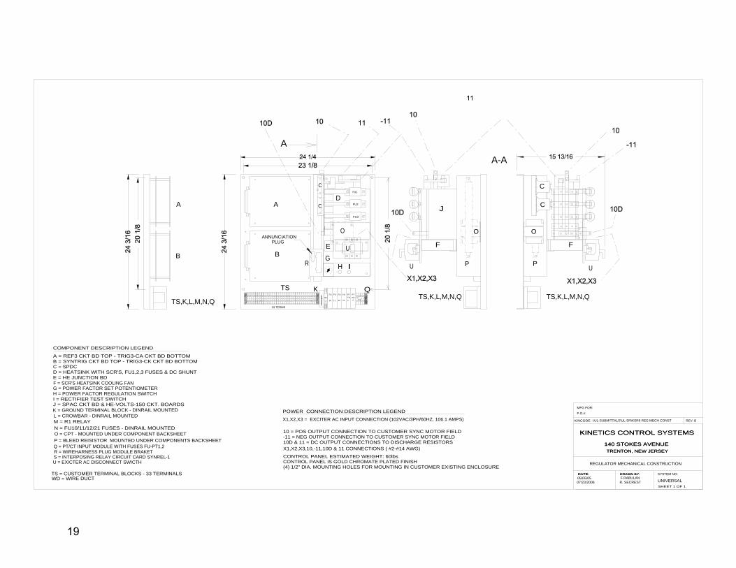
REGULATOR MECHANICAL CONSTRUCTION
UNIVERSALF.RABULAN05/05/05
O
P
C
C
A-A
A
B
C
D
E
J
O
B
C
P
TS,K,L,M,N,Q
O PLUG
ANNUNCIATION
A
12 22
11
14 24
21
A2-
A1+
TS,K,L,M,N,Q TS,K,L,M,N,Q
A
10 = POS OUTPUT CONNECTION TO CUSTOMER SYNC MOTOR FIELD-11 = NEG OUTPUT CONNECTION TO CUSTOMER SYNC MOTOR FIELD10D & 11 = DC OUTPUT CONNECTIONS TO DISCHARGE RESISTORS
POWER CONNECTION DESCRIPTION LEGEND
CONTROL PANEL ESTIMATED WEIGHT: 60lbsCONTROL PANEL IS GOLD CHROMATE PLATED FINISH(4) 1/2" DIA. MOUNTING HOLES FOR MOUNTING IN CUSTOMER EXISTING ENCLOSURE
X1,X2,X3 = EXCITER AC INPUT CONNECTION (102VAC/3PH/60HZ, 106.1 AMPS)
X1,X2,X3,10,-11,10D & 11 CONNECTIONS ( #2-#14 AWG)
9089888685848382
GR
N
CR
OW
BA
R
R187
FU
10
FU FU FU
11 12 21
PT PTFU FU1 2
CTCCTG
70 71
33 TERMS
B = SYNTRIG CKT BD TOP - TRIG3-CK CKT BD BOTTOMC = SPDCD = HEATSINK WITH SCR'S, FU1,2,3 FUSES & DC SHUNTE = HE JUNCTION BD
G = POWER FACTOR SET POTENTIOMETERH = POWER FACTOR REGULATION SWITCHI = RECTIFIER TEST SWITCHJ = SPAC CKT BD & HE-VOLTS-150 CKT. BOARDS
O = CPT - MOUNTED UNDER COMPONENT BACKSHEET
A = REF3 CKT BD TOP - TRIG3-CA CKT BD BOTTOM
COMPONENT DESCRIPTION LEGEND
L = CROWBAR - DINRAIL MOUNTED
P = BLEED REISISTOR MOUNTED UNDER COMPONENTS BACKSHEET
TS = CUSTOMER TERMINAL BLOCKS - 33 TERMINALS
N = FU10/11/12/21 FUSES - DINRAIL MOUNTED
F = SCR'S HEATSINK COOLING FAN
S = INTERPOSING RELAY CIRCUIT CARD SYNREL-1
K = GROUND TERMINAL BLOCK - DINRAIL MOUNTED
M = R1 RELAY
Q = PT/CT INPUT MODULE WITH FUSES FU-PT1,2
WD = WIRE DUCT
R = WIREHARNESS PLUG MODULE BRAKET
U = EXICTER AC DISCONNECT SWICTH
07/23/2006 R. SECREST
818063626160605756565655555544433535 3711-
10+
S-S+
U U
U
I:UL-SUBMITTALS\UL-SR\KSR6 REG MECH CONST
FU2
FU3
FU1
H IG
R
QKTS
F F
19

Kinetics Industries Inc. 140 Stokes Avenue Phone: 609-883-9700 Trenton, NJ 08638 Fax: 609-883-0025 email: [email protected] UL and Canadian UL Compliance- file number E302181 issued 2005-12-22 These units have been submitted to UL Laboratories for examination and testing in compliance with the requirements of the Standard for Power Conversion Equipment in effect as of the date of the UL Testing Labs report (2005-12-22). Short circuit tests were performed on submitted equipment and were found to be in accordance with the requirements in UL 508C. These same units have been examined and tested by UL laboratories and are certified to be in conformance with Canadian National Standard C22.2. The following information and markings are provided herein to comply with the applicable UL and Canadian standards. 1. “Use minimum 75’C wire only” 2. “Use copper conductors only” 3. Torque Markings:
Model KSR6C007PM11O Disconnect Switch: “Tighten terminals to 50 lb-in” Output Lug: “tighten terminals to 50 lb-in” Model KSR6F017PM11O Disconnect Switch: “Tighten terminals to 50 lb-in” Output Lug: “tighten terminals to 120 lb-in” Model KSR6C015PM22O Disconnect Switch: “Tighten terminals to 50 lb-in” Output Lug: “tighten terminals to 50 lb-in” Model KSR6F034PM22O Disconnect Switch: “Tighten terminals to 50 lb-in” Output Lug: “tighten terminals to 120 lb-in”
4. “Suitable for use on a circuit capable of delivering not more than 5.0 KA rms symmetrical
amperes”, where “@@@” is the input voltage of the device. This marking also includes the maximum voltage rating of the device.
5. “Integral solid state short circuit protection does not provide circuit protection. Branch circuit
protection must be provided in accordance with the National Electric Code and any additional local codes.”
6. “These devices provide solid state motor overload protection at 130% of FLA” Model differences – All KSR6 models are similar except for the overall ratings, base dimensions and heat sinks
20

Kinetics Industries Inc. 140 Stokes Avenue Phone: 609-883-9700 Trenton, NJ 08638 Fax: 609-883-0025 email: [email protected] This page left blank for notations
Copyright © 2005 Kinetics Industries, Inc. All rights reserved C;\Description of Kinetics KSR6--Exciter Regulator
21

Kinetics Industries Inc. 140 Stokes Avenue Phone: 609-883-9700 Trenton, NJ 08638 Fax: 609-883-0025 email: [email protected] This page left blank for notations
Copyright © 2005 Kinetics Industries, Inc. All rights reserved C;\Description of Kinetics KSR6--Exciter Regulator
22

Kinetics Industries Inc. 140 Stokes Avenue Phone: 609-883-9700 Trenton, NJ 08638 Fax: 609-883-0025 email: [email protected] This page left blank for notations
Copyright © 2005 Kinetics Industries, Inc. All rights reserved C;\Description of Kinetics KSR6--Exciter Regulator
23

Kinetics Industries Inc. 140 Stokes Avenue Trenton, NJ 08638
Operation and Maintenance Manual For
Kinetics Models KSR6C07PM11O KSR6 F17PM11O KSR6C15PM22O KSR6F34PM22O
Exciter Regulators for Brush Type Synchronous Motors - dtd 07/2006
Manufacturers of
SCR Exciter Regulators Line Regulated Diode Rectifiers through 2000 KW SCR Regulated Rectifiers through 2000 KW Synchronous Generator Excitation Systems Dry Type Transformers Magnet Power Supplies Flux Forcing Magnet Rectifiers Select-a-Pick Variable Voltage Magnet Rectifiers Elevator Power Supplies Crane Power Supplies Third Rail Powered Emergency Motor Generator Systems
Phone: 609-883-9700 sales ext 122 Fax: 609-883-0025 Email: [email protected]