kinetics™ seismic & wind design manual section d2 · are found in asce 7. the ibc version...
TRANSCRIPT
KINETICS™ Seismic & Wind Design Manual Section D2.0
SECTION D2.0 – TABLE OF CONTENTS PAGE 1 of 6 SECTION – D2.0B Toll Free (USA Only): 800-959-1229 RELEASED ON: 04/11/2014 International: 614-889-0480 FAX 614-889-0540 World Wide Web: www.kineticsnoise.com E-mail: [email protected] Dublin, Ohio, USA ∙ Mississauga, Ontario, Canada
SECTION D2.0 – TABLE OF CONTENTS
Title Section Revision Record D2.0A
D2.1 – Understanding Seismic for IBC
Title Section IBC Seismic - Introduction D2.1.1 Required Basic Project Information D2.1.2
Introduction D2.1.2.1
Building Use – Nature of Occupancy D2.1.2.2
Site Class – Soil Type D2.1.2.3
Mapped Acceleration Parameters D2.1.2.4
Seismic Design Category D2.1.2.5
Summary D2.1.2.6
Component Importance Factor D2.1.3 Introduction D2.1.3.1
Criteria for Assigning a Component Importance Factor D2.1.3.2
Summary D2.1.3.3
General Exemptions and Requirements D2.1.4 Introduction D2.1.4.1
Exemptions for Seismic Design Categories A and B D2.1.4.2
Exemptions for Seismic Design Category C D2.1.4.3
Exemptions for Seismic Design Categories D, E, and F D2.1.4.4
ASCE 7-98/02 and ASCE 7-05 D2.1.4.4.1
ASCE 7-10 D2.1.4.4.2
“Chandelier Exemption” D2.1.4.5
Component Size Relative to Building Structure D2.1.4.6
KINETICS™ Seismic & Wind Design Manual Section D2.0
SECTION D2.0 – TABLE OF CONTENTS PAGE 2 of 6 SECTION – D2.0B Toll Free (USA Only): 800-959-1229 RELEASED ON: 04/11/2014 International: 614-889-0480 FAX 614-889-0540 World Wide Web: www.kineticsnoise.com E-mail: [email protected] Dublin, Ohio, USA ∙ Mississauga, Ontario, Canada
Title Section Reference Documents D2.1.4.7
Allowable Stress Design (ASD) D2.1.4.8
Submittals and Construction Documents D2.1.4.9
Equipment Certification for Essential Facilities D2.1.4.10
Consequential or Collateral Damage D2.1.4.11
Flexibility of Components and Their Supports D2.1.4.12
Temporary or Movable Equipment D2.1.4.13
Summary D2.1.4.14
Exemptions for Piping Systems D2.1.5 Introduction D2.1.5.1
The 12″ Rule D2.1.5.2
Single Clevis Supported Pipe (Design Category A and B) D2.1.5.3
Single Clevis Supported Pipe (Design Category C) D2.1.5.4
Single Clevis Supported Pipe (Design Category D, E & F) D2.1.5.5
Trapeze Supported Pipe D2.1.5.6
Summary D2.1.5.7
Exemptions for HVAC Ductwork D2.1.6 Introduction D2.1.6.1
The 12″ Rule D2.1.6.2
Size Exemption D2.1.6.3
Trapeze Supported Ductwork D2.1.6.4
Restraint Allowance for In-Line Components D2.1.6.5
Summary D2.1.6.6
Exemptions for Electrical D2.1.7 Introduction D2.1.7.1
“Implied” Blanket Exemption D2.1.7.2
Conduit Size Exemptions D2.1.7.3
Trapeze Supported Electrical Distribution Systems D2.1.7.4
KINETICS™ Seismic & Wind Design Manual Section D2.0
SECTION D2.0 – TABLE OF CONTENTS PAGE 3 of 6 SECTION – D2.0B Toll Free (USA Only): 800-959-1229 RELEASED ON: 04/11/2014 International: 614-889-0480 FAX 614-889-0540 World Wide Web: www.kineticsnoise.com E-mail: [email protected] Dublin, Ohio, USA ∙ Mississauga, Ontario, Canada
Title Section The 12″ Rule D2.1.7.5
Summary D2.1.7.6
Seismic Design Forces D2.1.8 Introduction D2.1.8.1
Horizontal Seismic Design Force D2.1.8.2
Vertical Seismic Design Force D2.1.8.3
The Evolution of Pa and PR Factors D2.1.8.4
LRFD versus ASD D2.1.8.5
Summary D2.1.8.6
Anchorage of Components to the Building Structure D2.1.9 Introduction D2.1.9.1
General Guidelines for Component Anchorage D2.1.9.2
Anchorage in (Cracked) Concrete and Masonry D2.1.9.3
Undercut Anchors D2.1.9.4
Prying of Bolts and Anchors D2.1.9.5
Power Actuated or Driven Fasteners D2.1.9.7
Friction Clips D2.1.9.8
Summary D2.1.9.9
D2.2 – Understanding Wind for IBC
Title Section Introduction D2.2.1 Code Overview D2.2.2
Introduction D2.2.2.1
Wind Restraint for Rooftop Equipment D2.2.2.2
Building Classification for Wind Design D2.2.2.3
Basic Wind Speed & Wind Importance Factor D2.2.2.4
KINETICS™ Seismic & Wind Design Manual Section D2.0
SECTION D2.0 – TABLE OF CONTENTS PAGE 4 of 6 SECTION – D2.0B Toll Free (USA Only): 800-959-1229 RELEASED ON: 04/11/2014 International: 614-889-0480 FAX 614-889-0540 World Wide Web: www.kineticsnoise.com E-mail: [email protected] Dublin, Ohio, USA ∙ Mississauga, Ontario, Canada
Title Section Exposure Categories D2.2.2.5
Mean Roof Height D2.2.2.6
Summary D2.2.2.7
Evolution of Design Wind Loads D2.2.3 Introduction D2.2.3.1
Velocity Pressure D2.2.3.2
Velocity Pressure Exposure Coefficient D2.2.3.2.1
Topographic Factor D2.2.3.2.2
Wind Directionality Factor D2.2.3.2.3
IBC 2000 & 2003 (ASCE 7-89 & -02) D2.2.3.3
Gust Effect Factor D2.2.3.3.1
Net Force Coefficient D2.2.3.3.2
Design Wind Pressures for IBC 2000 & 2003 D2.2.3.3.3
IBC 2006 & 2009 (ASCE 7-05) D2.2.3.4
External Pressure Coefficient D2.2.3.4.1
Design Wind Pressures for IBC 2006 & 2009 D2.2.3.4.2
IBC 2012 (ASCE 7-10) D2.2.3.5
Buildings with 06 ′≤h D2.2.3.5.1
Buildings with 06 ′>h D2.2.3.5.2
Design Wind Pressures for IBC 2012 (ASCE 7-10) D2.2.3.5.3
Summary D2.2.3.6
D2.3 – Understanding Seismic for NBCC
Title Section
Introduction D2.3.1 Required Basic Project Information D2.3.2
Introduction D2.3.2.1
KINETICS™ Seismic & Wind Design Manual Section D2.0
SECTION D2.0 – TABLE OF CONTENTS PAGE 5 of 6 SECTION – D2.0B Toll Free (USA Only): 800-959-1229 RELEASED ON: 04/11/2014 International: 614-889-0480 FAX 614-889-0540 World Wide Web: www.kineticsnoise.com E-mail: [email protected] Dublin, Ohio, USA ∙ Mississauga, Ontario, Canada
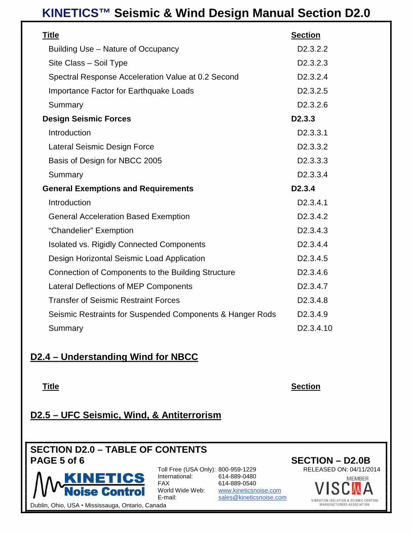
Title Section Building Use – Nature of Occupancy D2.3.2.2
Site Class – Soil Type D2.3.2.3
Spectral Response Acceleration Value at 0.2 Second D2.3.2.4
Importance Factor for Earthquake Loads D2.3.2.5
Summary D2.3.2.6
Design Seismic Forces D2.3.3 Introduction D2.3.3.1
Lateral Seismic Design Force D2.3.3.2
Basis of Design for NBCC 2005 D2.3.3.3
Summary D2.3.3.4
General Exemptions and Requirements D2.3.4 Introduction D2.3.4.1
General Acceleration Based Exemption D2.3.4.2
“Chandelier” Exemption D2.3.4.3
Isolated vs. Rigidly Connected Components D2.3.4.4
Design Horizontal Seismic Load Application D2.3.4.5
Connection of Components to the Building Structure D2.3.4.6
Lateral Deflections of MEP Components D2.3.4.7
Transfer of Seismic Restraint Forces D2.3.4.8
Seismic Restraints for Suspended Components & Hanger Rods D2.3.4.9
Summary D2.3.4.10
D2.4 – Understanding Wind for NBCC
Title Section
D2.5 – UFC Seismic, Wind, & Antiterrorism
KINETICS™ Seismic & Wind Design Manual Section D2.0
SECTION D2.0 – TABLE OF CONTENTS PAGE 6 of 6 SECTION – D2.0B Toll Free (USA Only): 800-959-1229 RELEASED ON: 04/11/2014 International: 614-889-0480 FAX 614-889-0540 World Wide Web: www.kineticsnoise.com E-mail: [email protected] Dublin, Ohio, USA ∙ Mississauga, Ontario, Canada
Title Section
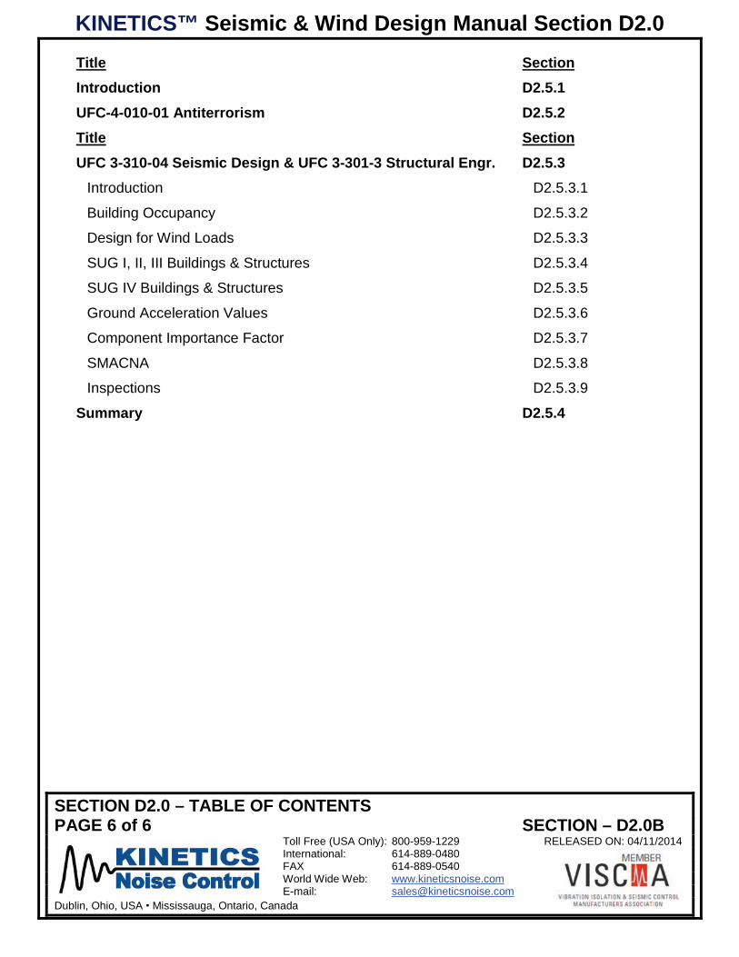
Introduction D2.5.1 UFC-4-010-01 Antiterrorism D2.5.2 Title Section UFC 3-310-04 Seismic Design & UFC 3-301-3 Structural Engr. D2.5.3
Introduction D2.5.3.1
Building Occupancy D2.5.3.2
Design for Wind Loads D2.5.3.3
SUG I, II, III Buildings & Structures D2.5.3.4
SUG IV Buildings & Structures D2.5.3.5
Ground Acceleration Values D2.5.3.6
Component Importance Factor D2.5.3.7
SMACNA D2.5.3.8
Inspections D2.5.3.9
Summary D2.5.4

KINETICS™ Seismic & Wind Design Manual Section D2.1
INTRODUCTIONPAGE 1 of 3 SECTION – D2.1.1
Toll Free (USA Only): 800-959-1229 RELEASED ON: 04/11/2014International: 614-889-0480FAX 614-889-0540World Wide Web: www.kineticsnoise.comE-mail: [email protected]
Dublin, Ohio, USA Cambridge, Ontario, Canada
IBC SEISMIC
D2.1.1 – Introduction:
The purpose of this section is to provide design professionals, contractors, and building officialsresponsible for the nonstructural components (MEP – Mechanical, Electrical, and Plumbing) withthe information and guidance required to ensure that the seismic restraints required for a specificproject are selected and/or designed, and installed in accordance with the provisions code. Thisguide will be written in several easily referenced sections that deal with specific portions of thecode.
This guide is based on the International Building Code (IBC). The 2000 IBC and the 2003 IBC arevery similar, and in fact are almost identical. When they are referenced in this section, it will be as2000/2003 IBC. The 2006 IBC and 2009 IBC are also nearly identical, and will be referenced inthe section as 2006/2009 IBC. The latest version of the IBC is dated 2012 and is substantiallydifferent from the previous versions, particularly in respect to the attachment of components toconcrete. The seismic provisions for all of the versions of the IBC for nonstructural componentsare found in ASCE 7. The IBC version with its corresponding ASCE 7 reference is shown in Table2.1.1-1.
Table D2.1.1-1; IBC & ASCE 7 References
INTERNATIONALBUILDING
CODE YEAR(IBC)
ASCE 7VERSION
ASCE 7SEISMIC
NON-STRUCTURALCOMPONENTS
CHAPTER
2000 98 92003 02 92006 05 132009 05 132012 10 13
Since all versions of the IBC are still currently adopted by various states, they will all be discussedand covered in this section.
The following References are used throughout Section D2.1.
1. 2007 ASHRAE HANDBOOK – Heating, Ventilating, and Air-Conditioning Applications;American Society of Heating, Refrigerating and Air-Conditioning Engineers, Inc., 1791 TullieCircle, N.E. Atlanta, GA 30329, 2007; Chapter 54 Pp 54-11 and 54-12.
KINETICS™ Seismic & Wind Design Manual Section D2.1
INTRODUCTIONPAGE 2 of 3 SECTION – D2.1.1
Toll Free (USA Only): 800-959-1229 RELEASED ON: 04/11/2014International: 614-889-0480FAX 614-889-0540World Wide Web: www.kineticsnoise.comE-mail: [email protected]
Dublin, Ohio, USA Cambridge, Ontario, Canada
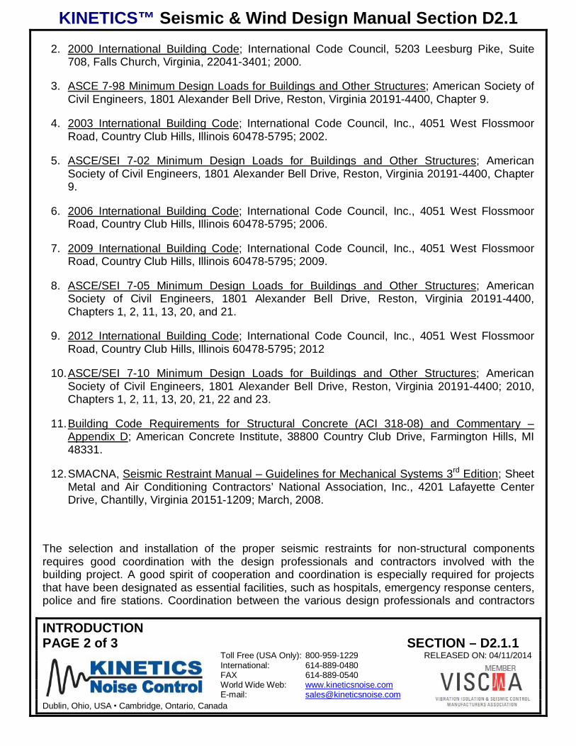
2. 2000 International Building Code; International Code Council, 5203 Leesburg Pike, Suite708, Falls Church, Virginia, 22041-3401; 2000.
3. ASCE 7-98 Minimum Design Loads for Buildings and Other Structures; American Society ofCivil Engineers, 1801 Alexander Bell Drive, Reston, Virginia 20191-4400, Chapter 9.
4. 2003 International Building Code; International Code Council, Inc., 4051 West FlossmoorRoad, Country Club Hills, Illinois 60478-5795; 2002.
5. ASCE/SEI 7-02 Minimum Design Loads for Buildings and Other Structures; AmericanSociety of Civil Engineers, 1801 Alexander Bell Drive, Reston, Virginia 20191-4400, Chapter9.
6. 2006 International Building Code; International Code Council, Inc., 4051 West FlossmoorRoad, Country Club Hills, Illinois 60478-5795; 2006.
7. 2009 International Building Code; International Code Council, Inc., 4051 West FlossmoorRoad, Country Club Hills, Illinois 60478-5795; 2009.
8. ASCE/SEI 7-05 Minimum Design Loads for Buildings and Other Structures; AmericanSociety of Civil Engineers, 1801 Alexander Bell Drive, Reston, Virginia 20191-4400,Chapters 1, 2, 11, 13, 20, and 21.
9. 2012 International Building Code; International Code Council, Inc., 4051 West FlossmoorRoad, Country Club Hills, Illinois 60478-5795; 2012
10. ASCE/SEI 7-10 Minimum Design Loads for Buildings and Other Structures; AmericanSociety of Civil Engineers, 1801 Alexander Bell Drive, Reston, Virginia 20191-4400; 2010,Chapters 1, 2, 11, 13, 20, 21, 22 and 23.
11. Building Code Requirements for Structural Concrete (ACI 318-08) and Commentary –Appendix D; American Concrete Institute, 38800 Country Club Drive, Farmington Hills, MI48331.
12. SMACNA, Seismic Restraint Manual – Guidelines for Mechanical Systems 3rd Edition; SheetMetal and Air Conditioning Contractors’ National Association, Inc., 4201 Lafayette CenterDrive, Chantilly, Virginia 20151-1209; March, 2008.
The selection and installation of the proper seismic restraints for non-structural componentsrequires good coordination with the design professionals and contractors involved with thebuilding project. A good spirit of cooperation and coordination is especially required for projectsthat have been designated as essential facilities, such as hospitals, emergency response centers,police and fire stations. Coordination between the various design professionals and contractors
KINETICS™ Seismic & Wind Design Manual Section D2.1
INTRODUCTIONPAGE 3 of 3 SECTION – D2.1.1
Toll Free (USA Only): 800-959-1229 RELEASED ON: 04/11/2014International: 614-889-0480FAX 614-889-0540World Wide Web: www.kineticsnoise.comE-mail: [email protected]
Dublin, Ohio, USA Cambridge, Ontario, Canada
will be a constant theme throughout this section. This coordination is vital for the followingreasons.
1. The seismic restraints that are installed for a system can and will interfere with those ofanother unless restraint locations are well coordinated.
2. The space required for the installed restraints can cause problems if non-structural wallsneed to be penetrated, or other non-structural components are in the designed load path forthe restraints.
The building end of the seismic restraints must always be attached to structure that is adequate tocarry the code mandated design seismic loads. It is the responsibility of the structural engineer ofrecord to verify this.
KINETICS™ Seismic & Wind Design Manual Section D2.1
REQUIRED BASIC PROJECT INFORMATIONPAGE 1 of 9 SECTION – D2.1.2
Toll Free (USA Only): 800-959-1229 RELEASED ON: 04/11/2014International: 614-889-0480FAX 614-889-0540World Wide Web: www.kineticsnoise.comE-mail: [email protected]
Dublin, Ohio, USA Cambridge, Ontario, Canada
REQUIRED BASIC PROJECT INFORMATION
D 2.1.2.1 Introduction:
As with any design job, there is certain basic information that is required before seismic restraintscan be selected and placed. The building owner, architect, and structural engineer make thedecisions that form the basis for the information required to select the seismic restraints for themechanical and electrical systems in the building. This information should be included in thespecification and bid package for the project. It also should appear on the first sheet of thestructural drawings. For consistency, it is good practice to echo this information in the specificationfor each building system, and on the first sheet of the drawings for each system. In this fashion,this information is available to all of the contractors and suppliers that will have a need to know.
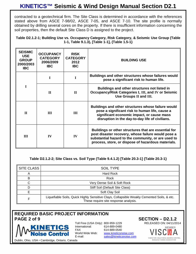
D2.1.2.2 Building Use – Nature of Occupancy (Section 1.5) [Section 1.5] {Section 1.5}1:
How a building is to be used greatly affects the level of seismic restraint that is required for thenon-structural components. In 2012 IBC, the building use will be defined by Risk Category. In the2006/2009 IBC the building use is defined through the Occupancy Category, which ranges from Ito IV. Occupancy Category I is applied to buildings where failure presents a low hazard to humanlife. At the other end of the range, Occupancy Category IV is applied to buildings which aredeemed to be essential. In 2012 IBC, the building use will be defined by Risk Category. The RiskCategories are assigned in exactly the same way as the Occupancy Categories in 2006/2009 IBC.In the first two versions of the IBC (2000/2003), the building use was defined though the SeismicUse Group which varied from I to III. Table 1-1 of ASCE 7-98/02 and ASCE 7-05 describes whichtypes of buildings are assigned to which Occupancy Category. Table D2.1.2-1 below summarizesthe information found in Tables 1-1 and 9.1.3 of ASCE 7-98/02, Table 1-1 of ASCE 7-05, andTable 1.5-1 of ASCE 7-10, and ties the Seismic Use Group from the previous versions of the IBCto the Occupancy Category. The nature of the building use, or its Occupancy Category, isdetermined by the building owner and the architect of record.
D2.1.2.3 Site Class – Soil Type (Sections 9.4.1.2.1, 9.4.1.2.2) [Section 11.4.2 & Chapter 20]{Section 11.4.2 & Chapter 20}:
The Site Class is related to the type of soil and rock strata that directly underlies the building site.
The Site Class ranges from A to F progressing from the stiffest to the softest strata. Table D2.1.2-2 lists the various Site Classes and their corresponding strata.
Generally the structural engineer is responsible for determining the Site Class for a project. If thestructural engineer’s firm does not have a geotechnical engineer on staff, this job will be
1 References in brackets (Section 1.5), [Section 1.5], and {Section 1.5} apply to sections, tables, and/or equations inASCE 7-98/02, ASCE 7-05, and ASCE 7-10 respectively which forms the basis for the seismic provisions in 2000/2003IBC, 2006/2009 IBC, and 2012 respectively.
KINETICS™ Seismic & Wind Design Manual Section D2.1
REQUIRED BASIC PROJECT INFORMATIONPAGE 2 of 9 SECTION – D2.1.2
Toll Free (USA Only): 800-959-1229 RELEASED ON: 04/11/2014International: 614-889-0480FAX 614-889-0540World Wide Web: www.kineticsnoise.comE-mail: [email protected]
Dublin, Ohio, USA Cambridge, Ontario, Canada
contracted to a geotechnical firm. The Site Class is determined in accordance with the referencesstated above from ASCE 7-98/02, ASCE 7-05, and ASCE 7-10. The site profile is normallyobtained by drilling several cores on the property. If there is insufficient information concerning thesoil properties, then the default Site Class D is assigned to the project.
Table D2.1.2-1; Building Use vs. Occupancy Category, Risk Category, & Seismic Use Group (Table1-1, Table 9.1.3), [Table 1-1], {Table 1.5-1}
SEISMICUSE
GROUP2000/2003
IBC
OCCUPANCYCATEGORY2006/2009
IBC
RISKCATEGORY
2012IBC
BUILDING USE
I
I I Buildings and other structures whose failures wouldpose a significant risk to human life.
II IIBuildings and other structures not listed in
Occupancy/Risk Categories I, III, and IV or SeismicUse Groups II and III.
II III III
Buildings and other structures whose failure wouldpose a significant risk to human life, cause asignificant economic impact, or cause massdisruption in the day-to-day life of civilians.
III IV IV
Buildings or other structures that are essential forpost disaster recovery, whose failure would pose asubstantial hazard to the community, or are used toprocess, store, or dispose of hazardous materials.
Table D2.1.2-2; Site Class vs. Soil Type (Table 9.4.1.2) [Table 20.3-1] {Table 20.3-1}
SITE CLASS SOIL TYPEA Hard RockB RockC Very Dense Soil & Soft RockD Stiff Soil (Default Site Class)E Soft Clay Soil
F Liquefiable Soils, Quick Highly Sensitive Clays, Collapsible Weakly Cemented Soils, & etc.These require site response analysis.
KINETICS™ Seismic & Wind Design Manual Section D2.1
REQUIRED BASIC PROJECT INFORMATIONPAGE 3 of 9 SECTION – D2.1.2
Toll Free (USA Only): 800-959-1229 RELEASED ON: 04/11/2014International: 614-889-0480FAX 614-889-0540World Wide Web: www.kineticsnoise.comE-mail: [email protected]
Dublin, Ohio, USA Cambridge, Ontario, Canada
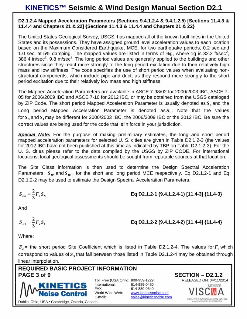
D2.1.2.4 Mapped Acceleration Parameters (Sections 9.4.1.2.4 & 9.4.1.2.5) [Sections 11.4.3 &11.4.4 and Chapters 21 & 22] {Sections 11.4.3 & 11.4.4 and Chapters 21 & 22}
The United States Geological Survey, USGS, has mapped all of the known fault lines in the UnitedStates and its possessions. They have assigned ground level acceleration values to each locationbased on the Maximum Considered Earthquake, MCE, for two earthquake periods, 0.2 sec and1.0 sec, at 5% damping. The mapped values are listed in terms of %g, where 1g is 32.2 ft/sec2,386.4 in/sec2, 9.8 m/sec2. The long period values are generally applied to the buildings and otherstructures since they react more strongly to the long period excitation due to their relatively highmass and low stiffness. The code specifies the use of short period values when evaluating non-structural components, which include pipe and duct, as they respond more strongly to the shortperiod excitation due to their relatively low mass and high stiffness.
The Mapped Acceleration Parameters are available in ASCE 7-98/02 for 2000/2003 IBC, ASCE 7-05 for 2006/2009 IBC and ASCE 7-10 for 2012 IBC, or may be obtained from the USGS catalogedby ZIP Code. The short period Mapped Acceleration Parameter is usually denoted as SS and theLong period Mapped Acceleration Parameter is denoted as 1S . Note that the valuesfor SS and 1S may be different for 2000/2003 IBC, the 2006/2009 IBC or the 2012 IBC. Be sure thecorrect values are being used for the code that is in force in your jurisdiction.
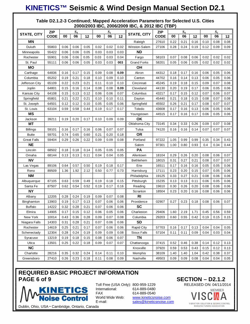
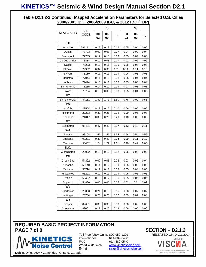
Special Note: For the purpose of making preliminary estimates, the long and short periodmapped acceleration parameters for selected U. S. cities are given in Table D2.1.2-3 (the valuesfor 2012 IBC have not been published at this time as indicated by TBP on Table D2.1.2-3). For theU. S. cities please refer to the data compiled by the USGS by ZIP CODE. For internationallocations, local geological assessments should be sought from reputable sources at that location.
The Site Class information is then used to determine the Design Spectral AccelerationParameters, DSS and 1DS , for the short and long period MCE respectively. Eq D2.1.2-1 and EqD2.1.2-2 may be used to estimate the Design Spectral Acceleration Parameters.
SaDS SFS32 Eq D2.1.2-1 (9.4.1.2.4-1) [11.4-3] {11.4-3}
And
11 32 SFS vD Eq D2.1.2-2 (9.4.1.2.4-2) [11.4-4] {11.4-4}
Where:
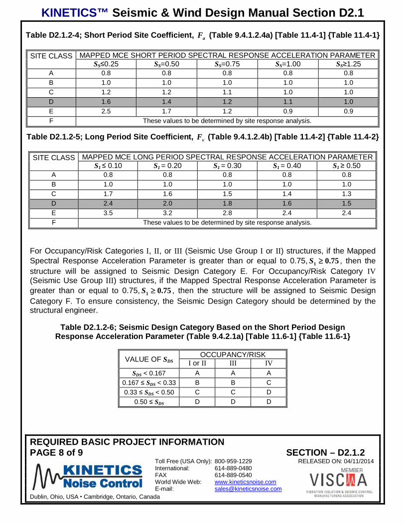
aF = the short period Site Coefficient which is listed in Table D2.1.2-4. The values for aF whichcorrespond to values of SS that fall between those listed in Table D2.1.2-4 may be obtained throughlinear interpolation.
KINETICS™ Seismic & Wind Design Manual Section D2.1
REQUIRED BASIC PROJECT INFORMATIONPAGE 4 of 9 SECTION – D2.1.2
Toll Free (USA Only): 800-959-1229 RELEASED ON: 04/11/2014International: 614-889-0480FAX 614-889-0540World Wide Web: www.kineticsnoise.comE-mail: [email protected]
Dublin, Ohio, USA Cambridge, Ontario, Canada
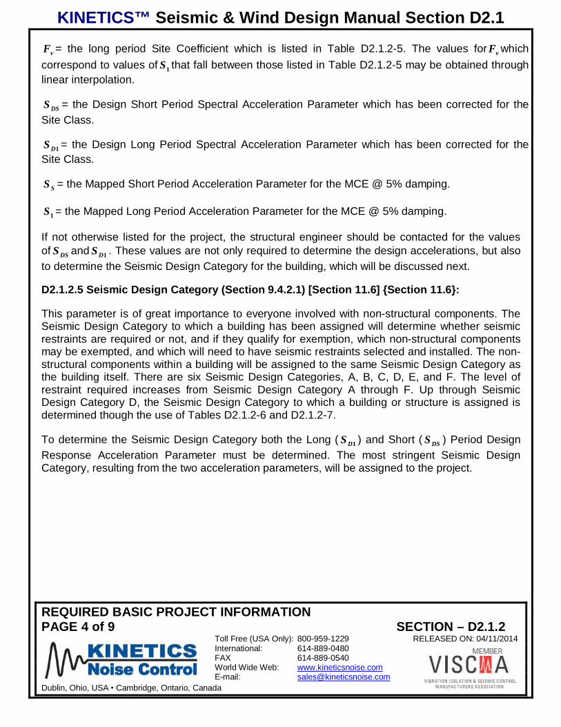
vF = the long period Site Coefficient which is listed in Table D2.1.2-5. The values for vF whichcorrespond to values of 1S that fall between those listed in Table D2.1.2-5 may be obtained throughlinear interpolation.
DSS = the Design Short Period Spectral Acceleration Parameter which has been corrected for theSite Class.
1DS = the Design Long Period Spectral Acceleration Parameter which has been corrected for theSite Class.
SS = the Mapped Short Period Acceleration Parameter for the MCE @ 5% damping.
1S = the Mapped Long Period Acceleration Parameter for the MCE @ 5% damping.
If not otherwise listed for the project, the structural engineer should be contacted for the valuesof DSS and 1DS . These values are not only required to determine the design accelerations, but alsoto determine the Seismic Design Category for the building, which will be discussed next.
D2.1.2.5 Seismic Design Category (Section 9.4.2.1) [Section 11.6] {Section 11.6}:
This parameter is of great importance to everyone involved with non-structural components. TheSeismic Design Category to which a building has been assigned will determine whether seismicrestraints are required or not, and if they qualify for exemption, which non-structural componentsmay be exempted, and which will need to have seismic restraints selected and installed. The non-structural components within a building will be assigned to the same Seismic Design Category asthe building itself. There are six Seismic Design Categories, A, B, C, D, E, and F. The level ofrestraint required increases from Seismic Design Category A through F. Up through SeismicDesign Category D, the Seismic Design Category to which a building or structure is assigned isdetermined though the use of Tables D2.1.2-6 and D2.1.2-7.
To determine the Seismic Design Category both the Long ( 1DS ) and Short ( DSS ) Period DesignResponse Acceleration Parameter must be determined. The most stringent Seismic DesignCategory, resulting from the two acceleration parameters, will be assigned to the project.

KINETICS™ Seismic & Wind Design Manual Section D2.1
REQUIRED BASIC PROJECT INFORMATIONPAGE 5 of 9 SECTION – D2.1.2
Toll Free (USA Only): 800-959-1229 RELEASED ON: 04/11/2014International: 614-889-0480FAX 614-889-0540World Wide Web: www.kineticsnoise.comE-mail: [email protected]
Dublin, Ohio, USA Cambridge, Ontario, Canada
Table D2.1.2-3; Mapped Acceleration Parameters for Selected U.S. Cities2000/2003 IBC, 2006/2009 IBC, & 2012 IBC (TBP)
STATE, CITY ZIPCODE
SS S1 STATE, CITY ZIPCODE
SS S10003
0609
12 0003
0609
12 0003
0609
12 0003
0609
12AL IL
Birmingham 35217 0.33 0.31 0.27 0.12 0.10 0.11 Chicago 60620 0.19 0.17 0.14 0.07 0.06 0.07Mobile 36610 0.13 0.12 0.11 0.06 0.05 0.06 Moline 61265 0.14 0.14 0.12 0.06 0.06 0.07
Montgomery 36104 0.17 0.16 0.14 0.08 0.07 0.08 Peoria 61605 0.18 0.18 0.15 0.09 0.08 0.08AR Rock Island 61201 0.13 0.13 0.11 0.06 0.06 0.07
Little Rock 72205 0.48 0.50 0.41 0.18 0.16 0.17 Rockford 61108 0.17 0.15 0.13 0.06 0.06 0.06AZ Springfield 62703 0.27 0.29 0.22 0.12 0.11 0.11
Phoenix 85034 0.23 0.19 0.18 0.07 0.06 0.06 INTucson 85739 0.33 0.29 0.28 0.09 0.08 0.08 Evansville 47712 0.82 0.72 0.62 0.23 0.21 0.22
CA Ft. Wayne 46835 0.17 0.15 0.12 0.06 0.06 0.06Fresno 93706 0.76 0.78 0.95 0.30 0.29 0.34 Gary 46402 0.18 0.16 0.13 0.07 0.06 0.07
Los Angeles 90026 1.55 2.25 2.78 0.60 0.83 0.99 Indianapolis 46260 0.18 0.19 0.16 0.09 0.08 0.09Oakland 94621 1.98 1.97 2.27 0.87 0.77 0.95 South Bend 46637 0.12 0.12 0.10 0.06 0.05 0.06
Sacramento 95823 0.59 0.64 0.70 0.23 0.25 0.30 KSSan Diego 92101 1.61 1.62 1.26 0.86 0.82 0.49 Kansas City 66103 0.12 0.13 0.12 0.06 0.06 0.07
San Francisco 94114 1.50 1.61 1.64 0.86 0.82 0.76 Topeka 66614 0.19 0.17 0.15 0.06 0.05 0.06San Jose 95139 2.17 1.60 1.50 0.78 0.60 0.60 Wichita 67217 0.14 0.14 0.11 0.06 0.05 0.06
CO KYColorado Springs 80913 0.18 0.22 0.19 0.06 0.06 0.07 Ashland 41101 0.22 0.19 0.16 0.09 0.07 0.08
Denver 80239 0.19 0.21 0.18 0.06 0.06 0.06 Covington 41011 0.19 0.18 0.15 0.09 0.08 0.08CT Louisville 40202 0.25 0.25 0.21 0.12 0.10 0.11
Bridgeport 06606 0.34 0.27 0.21 0.09 0.06 0.07 LAHartford 06120 0.27 0.24 0.18 0.09 0.06 0.07 Baton Rouge 70807 0.14 0.12 0.11 0.06 0.05 0.06
New Haven 06511 0.29 0.25 0.19 0.08 0.06 0.07 New Orleans 70116 0.13 0.11 0.10 0.06 0.05 0.06Waterbury 06702 0.29 0.25 0.19 0.09 0.06 0.07 Shreveport 71106 0.17 0.15 0.13 0.08 0.07 0.07
FL MAFt. Lauderdale 33328 0.07 0.06 0.05 0.03 0.02 0.03 Boston 02127 0.33 0.28 0.22 0.09 0.07 0.07Jacksonville 32222 0.14 0.14 0.11 0.07 0.06 0.06 Lawrence 01843 0.38 0.33 0.25 0.09 0.07 0.08
Miami 33133 0.06 0.05 0.05 0.02 0.02 0.02 Lowell 01851 0.36 0.31 0.24 0.09 0.07 0.08St. Petersburg 33709 0.08 0.07 0.06 0.04 0.03 0.03 New Bedford 02740 0.26 0.22 0.18 0.08 0.06 0.06
Tampa 33635 0.08 0.07 0.06 0.03 0.03 0.04 Springfield 01107 0.26 0.23 0.18 0.09 0.07 0.07GA Worchester 01602 0.27 0.24 0.18 0.09 0.07 0.07
Atlanta 30314 0.26 0.23 0.19 0.11 0.09 0.09 MYAugusta 30904 0.42 0.38 0.30 0.15 0.12 0.12 Baltimore 21218 0.20 0.17 0.14 0.06 0.05 0.06
Columbia 31907 0.17 0.15 0.13 0.09 0.07 0.08 MESavannah 31404 0.42 0.43 0.33 0.15 0.13 0.13 Augusta 04330 0.33 0.30 0.24 0.10 0.08 0.08
IA Portland 04101 0.37 0.32 0.25 0.10 0.08 0.08Council Bluffs 41011 0.19 0.18 0.15 0.09 0.08 0.08 MI
Davenport 52803 0.13 0.13 0.11 0.06 0.06 0.07 Detroit 48207 0.12 0.12 0.10 0.05 0.04 0.05Des Moines 50310 0.07 0.08 0.07 0.04 0.04 0.05 Flint 48506 0.09 0.09 0.08 0.04 0.04 0.05
ID Grand Rapids 49503 0.09 0.09 0.08 0.04 0.04 0.05Boise 83705 0.35 0.30 0.31 0.11 0.10 0.11 Kalamazoo 49001 0.12 0.11 0.09 0.05 0.05 0.05
Pocatello 83201 0.60 0.63 0.57 0.18 0.19 0.18 Lansing 48910 0.11 0.10 0.09 0.04 0.04 0.05
KINETICS™ Seismic & Wind Design Manual Section D2.1
REQUIRED BASIC PROJECT INFORMATIONPAGE 6 of 9 SECTION – D2.1.2
Toll Free (USA Only): 800-959-1229 RELEASED ON: 04/11/2014International: 614-889-0480FAX 614-889-0540World Wide Web: www.kineticsnoise.comE-mail: [email protected]
Dublin, Ohio, USA Cambridge, Ontario, Canada
Table D2.1.2-3 Continued; Mapped Acceleration Parameters for Selected U.S. Cities2000/2003 IBC, 2006/2009 IBC, & 2012 IBC (TBP)
STATE, CITY ZIPCODE
SS S1 STATE, CITY ZIPCODE
SS S10003
0609
12 0003
0609
12 0003
0609
12 0003
0609
12MN Raleigh 27610 0.22 0.21 0.16 0.10 0.08 0.08
Duluth 55803 0.06 0.06 0.05 0.02 0.02 0.02 Winston-Salem 27106 0.28 0.24 0.19 0.12 0.09 0.09Minneapolis 55422 0.06 0.06 0.05 0.03 0.03 0.03 NDRochester 55901 0.06 0.06 0.05 0.03 0.03 0.04 Fargo 58103 0.07 0.08 0.06 0.02 0.02 0.02St. Paul 55111 0.06 0.06 0.05 0.03 0.03 003 Grand Forks 58201 0.05 0.06 0.05 0.02 0.02 0.02
MO OHCarthage 64836 0.16 0.17 0.15 0.09 0.08 0.09 Akron 44312 0.18 0.17 0.16 0.06 0.05 0.06Columbia 65202 0.19 0.21 0.18 0.10 0.09 0.10 Canton 44702 0.16 0.14 0.13 0.06 0.05 0.06
Jefferson City 65109 0.22 0.23 0.21 0.11 0.10 0.10 Cincinnati 45245 0.19 0.18 0.15 0.09 0.07 0.08Joplin 64801 0.15 0.16 0.14 0.08 0.08 0.09 Cleveland 44130 0.20 0.19 0.17 0.06 0.05 0.06
Kansas City 64108 0.15 0.13 0.12 0.06 0.06 0.07 Columbus 43217 0.17 0.15 0.12 0.07 0.06 0.07Springfield 65801 0.21 0.22 0.21 0.10 0.10 0.11 Dayton 45440 0.21 0.18 0.15 0.08 0.07 0.08St. Joseph 64501 0.12 0.12 0.10 0.05 0.05 0.06 Springfield 45502 0.26 0.21 0.17 0.08 0.07 0.07St. Louis 63104 0.59 0.58 0.44 0.19 0.17 0.17 Toledo 43608 0.17 0.16 0.13 0.06 0.05 0.06
MS Youngstown 44515 0.17 0.16 0.17 0.06 0.05 0.06Jackson 39211 0.19 0.20 0.17 0.10 0.09 0.09 OK
MT Oklahoma City 73145 0.34 0.33 0.26 0.09 0.07 0.08
Billings 59101 0.16 0.17 0.16 0.06 0.07 0.07 Tulsa 74120 0.16 0.16 0.14 0.07 0.07 0.07Butte 59701 0.74 0.65 0.60 0.21 0.20 0.18 OR
Great Falls 59404 0.29 0.26 0.22 0.09 0.09 0.08 Portland 97222 1.05 0.99 0.99 0.35 0.34 0.43NE Salem 97301 1.00 0.80 0.93 0.4 0.34 0.44
Lincoln 68502 0.18 0.18 0.14 0.05 0.05 0.05 PAOmaha 68144 0.13 0.13 0.11 0.04 0.04 0.05 Allentown 18104 0.29 0.26 0.20 0.08 0.06 0.07
NV Bethlehem 18015 0.31 0.27 0.21 0.08 0.07 0.07Las Vegas 89106 0.64 0.57 0.50 0.19 0.18 0.17 Erie 16511 0.17 0.16 0.16 0.05 0.05 0.06
Reno 89509 1.36 1.92 2.12 0.50 0.77 0.73 Harrisburg 17111 0.23 0.20 0.15 0.07 0.05 0.06NM Philadelphia 19125 0.33 0.27 0.21 0.08 0.06 0.06
Albuquerque 87105 0.63 0.59 0.49 0.19 0.18 0.15 Pittsburgh 15235 0.13 0.13 0.11 0.06 0.05 0.06Santa Fe 87507 0.62 0.54 0.52 0.19 0.17 0.16 Reading 19610 0.30 0.26 0.20 0.08 0.06 0.06
NY Scranton 18504 0.23 0.20 0.16 0.08 0.06 0.06Albany 12205 0.28 0.24 0.19 0.09 0.07 0.08 RI
Binghamton 13903 0.19 0.17 0.13 0.07 0.06 0.06 Providence 02907 0.27 0.23 0.18 0.08 0.06 0.07Buffalo 14222 0.32 0.28 0.21 0.07 0.06 0.06 SCElmira 14905 0.17 0.15 0.12 0.06 0.05 0.06 Charleston 29406 1.60 2.19 1.71 0.45 0.56 0.59
New York 10014 0.43 0.36 0.28 0.09 0.07 0.08 Columbia 29203 0.60 0.55 0.42 0.19 0.15 0.15Niagara Falls 14303 0.31 0.28 0.21 0.07 0.06 0.06 SD
Rochester 14619 0.25 0.21 0.17 0.07 0.06 0.06 Rapid City 57703 0.16 0.17 0.13 0.04 0.04 0.05Schenectady 12304 0.28 0.24 0.19 0.09 0.09 0.08 Sioux Falls 57104 0.11 0.11 0.09 0.04 0.03 0.04
Syracuse 13219 0.19 0.18 0.15 0.08 0.06 0.07 TNUtica 13501 0.25 0.22 0.18 0.09 0.07 0.07 Chattanooga 37415 0.52 0.46 0.38 0.14 0.12 0.13NC Knoxville 37920 0.59 0.53 0.43 0.15 0.12 0.13
Charlotte 28216 0.35 0.32 0.24 0.14 0.11 0.10 Memphis 38109 1.40 1.40 1.04 0.42 0.38 0.37Greensboro 27410 0.26 0.23 0.18 0.11 0.08 0.09 Nashville 49503 0.09 0.09 0.08 0.04 0.04 0.05
KINETICS™ Seismic & Wind Design Manual Section D2.1
REQUIRED BASIC PROJECT INFORMATIONPAGE 7 of 9 SECTION – D2.1.2
Toll Free (USA Only): 800-959-1229 RELEASED ON: 04/11/2014International: 614-889-0480FAX 614-889-0540World Wide Web: www.kineticsnoise.comE-mail: [email protected]
Dublin, Ohio, USA Cambridge, Ontario, Canada
Table D2.1.2-3 Continued; Mapped Acceleration Parameters for Selected U.S. Cities2000/2003 IBC, 2006/2009 IBC, & 2012 IBC (TBP)
STATE, CITY ZIPCODE
SS S1
0003
0609 12 00
030609 12
TXAmarillo 79111 0.17 0.18 0.16 0.05 0.04 0.05Austin 78703 0.09 0.08 0.07 0.04 0.03 0.04
Beaumont 77705 0.12 0.10 0.09 0.05 0.04 0.05Corpus Christi 78418 0.10 0.08 0.07 0.02 0.02 0.02
Dallas 75233 0.12 0.11 0.10 0.06 0.05 0.05El Paso 79932 0.37 0.33 0.31 0.11 0.11 0.10
Ft. Worth 76119 0.11 0.11 0.09 0.06 0.05 0.05Houston 77044 0.11 0.10 0.08 0.05 0.04 0.04Lubbock 79424 0.10 0.11 0.08 0.03 0.03 0.04
San Antonio 78235 0.14 0.12 0.09 0.03 0.03 0.03Waco 76704 0.10 0.09 0.08 0.05 0.04 0.05
UTSalt Lake City 84111 1.82 1.71 1.50 0.78 0.09 0.55
VANorfolk 23504 0.13 0.12 0.10 0.06 0.05 0.05
Richmond 23233 0.32 0.25 0.22 0.09 0.06 0.07Roanoke 24017 0.30 0.26 0.20 0.10 0.08 0.08
VTBurlington 05401 0.47 0.40 0.37 0.13 0.10 0.11
WASeattle 98108 1.56 1.57 1.54 0.54 0.54 0.59
Spokane 99201 0.38 0.40 0.34 0.09 0.11 0.12Tacoma 98402 1.24 1.22 1.31 0.40 0.42 0.06
D.C.Washington 20002 0.18 0.15 0.12 0.06 0.05 0.05
WIGreen Bay 54302 0.07 0.06 0.06 0.03 0.03 0.04Kenosha 53140 0.14 0.12 0.10 0.05 0.05 0.06Madison 53714 0.12 0.11 0.09 0.05 0.04 0.05
Milwaukee 53221 0.12 0.11 0.09 0.05 0.05 0.05Racine 53402 0.13 0.12 0.10 0.05 0.05 0.05
Superior 54880 0.06 0.06 0.05 0.02 0.2 0.02WV
Charleston 25303 0.21 0.19 0.15 0.08 0.07 0.07Huntington 25704 0.23 0.20 0.16 0.09 0.07 0.08
WYCasper 82601 0.38 0.39 0.30 0.08 0.08 0.08
Cheyenne 82001 0.19 0.20 0.19 0.06 0.05 0.06
KINETICS™ Seismic & Wind Design Manual Section D2.1
REQUIRED BASIC PROJECT INFORMATIONPAGE 8 of 9 SECTION – D2.1.2
Toll Free (USA Only): 800-959-1229 RELEASED ON: 04/11/2014International: 614-889-0480FAX 614-889-0540World Wide Web: www.kineticsnoise.comE-mail: [email protected]
Dublin, Ohio, USA Cambridge, Ontario, Canada
Table D2.1.2-4; Short Period Site Coefficient, aF (Table 9.4.1.2.4a) [Table 11.4-1] {Table 11.4-1}
SITE CLASS MAPPED MCE SHORT PERIOD SPECTRAL RESPONSE ACCELERATION PARAMETERSS 0.25 SS=0.50 SS=0.75 SS=1.00 SS 1.25
A 0.8 0.8 0.8 0.8 0.8B 1.0 1.0 1.0 1.0 1.0C 1.2 1.2 1.1 1.0 1.0D 1.6 1.4 1.2 1.1 1.0E 2.5 1.7 1.2 0.9 0.9F These values to be determined by site response analysis.
Table D2.1.2-5; Long Period Site Coefficient, vF (Table 9.4.1.2.4b) [Table 11.4-2] {Table 11.4-2}
SITE CLASS MAPPED MCE LONG PERIOD SPECTRAL RESPONSE ACCELERATION PARAMETERS1 0.10 S1 = 0.20 S1 = 0.30 S1 = 0.40 S1 0.50
A 0.8 0.8 0.8 0.8 0.8B 1.0 1.0 1.0 1.0 1.0C 1.7 1.6 1.5 1.4 1.3D 2.4 2.0 1.8 1.6 1.5E 3.5 3.2 2.8 2.4 2.4F These values to be determined by site response analysis.
For Occupancy/Risk Categories I, II, or III (Seismic Use Group I or II) structures, if the MappedSpectral Response Acceleration Parameter is greater than or equal to 0.75, 75.01S , then thestructure will be assigned to Seismic Design Category E. For Occupancy/Risk Category IV(Seismic Use Group III) structures, if the Mapped Spectral Response Acceleration Parameter isgreater than or equal to 0.75, 75.01S , then the structure will be assigned to Seismic DesignCategory F. To ensure consistency, the Seismic Design Category should be determined by thestructural engineer.
Table D2.1.2-6; Seismic Design Category Based on the Short Period DesignResponse Acceleration Parameter (Table 9.4.2.1a) [Table 11.6-1] {Table 11.6-1}
VALUE OF SDSOCCUPANCY/RISK
I or II(I)
III(II)
IV(III)SDS < 0.167 A A A
0.167 SDS < 0.33 B B C0.33 SDS < 0.50 C C D
0.50 SDS D D D
KINETICS™ Seismic & Wind Design Manual Section D2.1
REQUIRED BASIC PROJECT INFORMATIONPAGE 9 of 9 SECTION – D2.1.2
Toll Free (USA Only): 800-959-1229 RELEASED ON: 04/11/2014International: 614-889-0480FAX 614-889-0540World Wide Web: www.kineticsnoise.comE-mail: [email protected]
Dublin, Ohio, USA Cambridge, Ontario, Canada
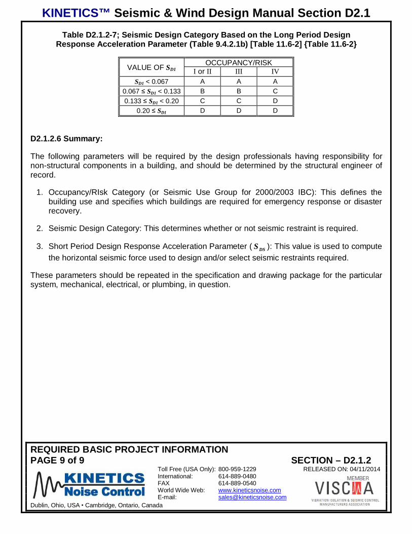
Table D2.1.2-7; Seismic Design Category Based on the Long Period DesignResponse Acceleration Parameter (Table 9.4.2.1b) [Table 11.6-2] {Table 11.6-2}
VALUE OF SD1OCCUPANCY/RISK
I or II(I)
III(II)
IV(III)SD1 < 0.067 A A A
0.067 SD1 < 0.133 B B C0.133 SD1 < 0.20 C C D
0.20 SD1 D D D
D2.1.2.6 Summary:
The following parameters will be required by the design professionals having responsibility fornon-structural components in a building, and should be determined by the structural engineer ofrecord.
1. Occupancy/RIsk Category (or Seismic Use Group for 2000/2003 IBC): This defines thebuilding use and specifies which buildings are required for emergency response or disasterrecovery.
2. Seismic Design Category: This determines whether or not seismic restraint is required.
3. Short Period Design Response Acceleration Parameter ( DSS ): This value is used to computethe horizontal seismic force used to design and/or select seismic restraints required.
These parameters should be repeated in the specification and drawing package for the particularsystem, mechanical, electrical, or plumbing, in question.
KINETICS™ Seismic & Wind Design Manual Section D2.1
COMPONENT IMPORTANCE FACTORPAGE 1 of 3 SECTION – D2.1.3
Toll Free (USA Only): 800-959-1229 RELEASED ON: 04/11/2014International: 614-889-0480FAX 614-889-0540World Wide Web: www.kineticsnoise.comE-mail: [email protected]
Dublin, Ohio, USA Cambridge, Ontario, Canada
COMPONENT IMPORTANCE FACTOR
D2.1.3.1 Introduction:
MEP components and systems are categorized in ASCE 7-98/02, ASCE 7-05, and ASCE 7-10 asnon-structural components. There are just two values for the Component Importance Factors fornon-structural components, 1.0 and 1.5, which are not directly linked to the importance factor forthe building structure. The Component Importance Factor is designated as PI in the body of thecode. All non-structural components must be assigned a component importance factor. Thedesign professional that has responsibility for the MEP system in question is also responsible forassigning the Component Importance Factor to that system.
D2.1.3.2 Criteria for Assigning a Component Importance Factor (Sections 9.6.1 and 9.6.1.5)[Section 13.1.3] {Section 13.1.3}1:
For non-structural components, the Component Importance Factor ( PI ) assigned to thecomponents shall be determined as follows.
1. If the MEP system is required to remain in place and function for life-safety purposesfollowing and earthquake the Component Importance Factor assigned to the non-structuralcomponent shall be 1.5. Some examples of this type of system would be;
a. Fire sprinkler piping and fire suppression systems.
b. Smoke removal and fresh air ventilation systems.
c. Systems required for maintaining the proper air pressure in patient hospital rooms toprevent the transmission of infectious diseases.
d. Systems that maintain proper air pressure, temperature, and humidity in surgical suites,bio-hazard labs, and clean rooms.
e. Medical gas lines.
f. Steam lines or high pressure hot water lines.
2. If the non-structural component contains or is used to transport hazardous materials, ormaterials that are toxic if released in quantities that exceed the exempted limits a ComponentImportance Factor of 1.5 shall be assigned to that component. Examples are as follows.
a. Systems using natural gas.
1 References in brackets (Sections 9.6.1 and 9.6.1.5), [Section 13.1.3], {Section 13.1.3} apply to sections, tables, and/orequations in ASCE 7-98/02, ASCE 7-05, and ASCE 7-10 respectively which forms the basis for the seismic provisions in2000/2003 IBC, 2006/2009, and 2012 IBC respectively.
KINETICS™ Seismic & Wind Design Manual Section D2.1
COMPONENT IMPORTANCE FACTORPAGE 2 of 3 SECTION – D2.1.3
Toll Free (USA Only): 800-959-1229 RELEASED ON: 04/11/2014International: 614-889-0480FAX 614-889-0540World Wide Web: www.kineticsnoise.comE-mail: [email protected]
Dublin, Ohio, USA Cambridge, Ontario, Canada
b. Systems requiring fuel oil.
c. Systems used to exhaust laboratory fume hoods.
d. Boilers, furnaces and flue systems.
e. Systems that are used to ventilate bio-hazard areas and infectious patient rooms.
f. Chemical or by-product systems which are required for industrial processes.
3. If the non-structural component is in or attached to a building that has been assigned toOccupancy/Risk Category IV (Seismic Use Group III), i.e. essential or critical facilities, and isrequired for the continued operation of that facility following an earthquake, then aComponent Importance Factor of 1.5 shall be assigned to that component. Hospitals,emergency response centers, police stations, fire stations, and etc. fall underOccupancy/Risk Category IV (Seismic Use Group III). The failure of any system could causethe portion of the building it serves to be evacuated and unusable would cause that systemand its components to be assigned a Component Importance Factor of 1.5. Even the failureof domestic water lines can flood a building and render it uninhabitable. So, all of the itemslisted above under items 1 and 2 would apply to facilities in Occupancy/Risk Category IV(Seismic Use Group III).
4. If the non-structural component that is located in or attached to an Occupancy/Risk CategoryIV (Seismic Use Group III) facility and its failure would impair the operation of that facility,then a Component Importance Factor of 1.5 shall be assigned to that component. Thisimplies that any non critical non-structural component that is located above a non-structuralcomponent with a Component Importance Factor of 1.5 must be assigned a ComponentImportance Factor of 1.5, or otherwise supported in a fashion that the more critical systemwould not be damaged.
5. All non-structural components that are not covered under items 1, 2, 3, or 4 may be assigneda Component Importance Factor of 1.0.
D2.1.3.3 Summary:
The Component Importance Factor is very important to the designer responsible for selecting andcertifying the seismic restraints for a non-structural component. This factor is a direct multiplier forthe horizontal seismic design force, which shall be discussed in a later section. The ComponentImportance Factor will also be a key indicator as to whether a particular component will qualify foran exemption or not. If a Component Importance Factor has not been assigned, the designerresponsible for selecting the seismic restraints must assume that the Component ImportanceFactor is equal to 1.5. If the non-structural component could actually be assigned a ComponentImportance Factor of 1.0, this could result in a large increase in the size and number of restraintsrequired along with a corresponding increase in the cost for the system.
KINETICS™ Seismic & Wind Design Manual Section D2.1
COMPONENT IMPORTANCE FACTORPAGE 3 of 3 SECTION – D2.1.3
Toll Free (USA Only): 800-959-1229 RELEASED ON: 04/11/2014International: 614-889-0480FAX 614-889-0540World Wide Web: www.kineticsnoise.comE-mail: [email protected]
Dublin, Ohio, USA Cambridge, Ontario, Canada
It is in the best interest of the design professionals responsible for the non-structural componentsto properly assign the Component Importance Factor to those components. The ComponentImportance Factor for each non-structural component should be clearly indicated on the drawingsthat are distributed to other design professionals, contractors, suppliers, and building officials.
KINETICS™ Seismic & Wind Design Manual Section D2.1
GENERAL EXEMPTIONS AND REQUIREMENTSPAGE 1 of 8 SECTION – D2.1.4
Toll Free (USA Only): 800-959-1229 RELEASED ON: 04/11/2014International: 614-889-0480FAX 614-889-0540World Wide Web: www.kineticsnoise.comE-mail: [email protected]
Dublin, Ohio, USA Cambridge, Ontario, Canada
GENERAL EXEMPTIONS AND REQUIREMENTS
D2.1.4.1 Introduction:
The International Building Codes (IBC’s) allow certain exemptions to be made for MEP(Mechanical, Electrical, and Plumbing) components and other non-structural components from theneed for seismic restraint. These exemptions are based on the Seismic Design Category, theComponent Importance Factor, the size, the weight, and the vertical location within the building ofthe components.
There are further general provisions in the IBC pertaining to MEP components and other non-structural components that must be acknowledged at the outset of a project. These are provisionsranging from the upper bound size for a component to the component certifications anddocumentation required.
This section will present the general exemptions for MEP components and other non-structuralcomponents and discuss the general requirements that apply to them.
D2.1.4.2 Exemptions for Seismic Design Categories A and B (Sections 9.6.1-1 & 9.6.1-3)[Sections 13.1.4-1 & 13.1.4-2] {Sections 11.7, 13.1.4-3, & 13.1.4-4}1:
MEP components that are located in or on buildings that have been assigned to Seismic DesignCategories A and B, and other non-structural components that have been assigned to SeismicDesign Category B, are exempt from the requirements for seismic restraints. These twoexemptions point out the need for having the correct seismic deign in formation for the projectavailable to all of the design professionals and contractors during the bidding stage of the project.Being able to use these exemptions can save the contractors as much as 10% to 15% in theircosts.
For example, a critical piece of information required at the outset is the Site Class. If the SiteClass has not been determined by a qualified geotechnical engineer, then Site Class D must beassumed. The resulting combination of the mapped acceleration parameters and soil profile ofSite Class D may force the project to be assigned to Seismic Design Category C which in turnforces the requirement for seismic restraints. If instead the Site Class had been determined to beSite Class B by a qualified geotechnical engineer, then the project may have been found to fallinto Seismic Design Category A or B, thus eliminating the need for seismic restraints for thenonstructural components.
1 References in brackets (Section 9.6.1-1 & 9.6.1-2) [Section 13.1.4-1 & 13.1.4-2], {Sections 11.7, 13.1.4-3, & 13.1.4-4}apply to sections, tables, and/or equations in ASCE 7-98/02, ASCE 7-05, ASCE 7-12 respectively, which forms the basisfor the seismic provisions in 2000/2003 IBC and 2006/2009 IBC, 2012 IBC respectively.

KINETICS™ Seismic & Wind Design Manual Section D2.1
GENERAL EXEMPTIONS AND REQUIREMENTSPAGE 2 of 8 SECTION – D2.1.4
Toll Free (USA Only): 800-959-1229 RELEASED ON: 04/11/2014International: 614-889-0480FAX 614-889-0540World Wide Web: www.kineticsnoise.comE-mail: [email protected]
Dublin, Ohio, USA Cambridge, Ontario, Canada
D2.1.4.3 Exemptions for Seismic Design Category C (Section 9.6.1-4) [Section 13.1.4-3]{Section 13.1.4-5}:
MEP components that have been assigned to Seismic Design Category C, and that have alsobeen assigned a Component Importance Factor of 1.0, are exempt from the requirements forseismic restraints. In this case it is very important that the design professionals responsible for thevarious MEP components assign the correct Component Importance Factors to those systemsand components. If no Component Importance Factor is assigned, the installing contractor shouldprudently assume that the Component Importance Factor is equal to 1.5, and provide restraints forthat system or component. This is particularly true of duct runs where it is very likely that theventilation components may also be required for smoke control.
It is also critical to know which MEP systems and components have a component ImportanceFactor of 1.0 and which ones have a Component Importance Factor of 1.5. To the extent possible,those with Component Importance Factors equal to 1.5 should be installed above those withComponent Importance Factors equal to 1.0 in order to reduce the over all number of restraintsneeded for the project.
D2.1.4.4 Exemptions for Seismic Design Categories D, E, and F
D2.1.4.4.1 ASCE 7-98/02 and ASCE 7-05 (Sections 9.6.1-5 and 9.1.6-6) [Sections 13.1.4-4 and13.1.4-5] also ASCE 7-10, IBC 2012 with special conditions indicated in line item 3 below:
There are basically three exemptions that apply here.
1. MEP components that:
a. Are in Seismic Design Categories D, E, and F.
b. Have a Component Importance Factor equal to 1.0,
c. Have flexible connections between the components and all associated duct, piping,conduit.
d. Are mounted at 4 ft (1.22 m) or less above a floor level.
e. And weigh 400 lbs (181 kg) or less.
2. MEP components that:
a. Are in Seismic Design Categories D, E, and F.
b. Have a Component Importance Factor equal to 1.0.
c. Have flexible connections between the components and all associated duct, piping,conduit.
KINETICS™ Seismic & Wind Design Manual Section D2.1
GENERAL EXEMPTIONS AND REQUIREMENTSPAGE 3 of 8 SECTION – D2.1.4
Toll Free (USA Only): 800-959-1229 RELEASED ON: 04/11/2014International: 614-889-0480FAX 614-889-0540World Wide Web: www.kineticsnoise.comE-mail: [email protected]
Dublin, Ohio, USA Cambridge, Ontario, Canada
d. And weigh 20 lbs (9.1 kg) or less.
3. MEP distribution systems that:
a. Are in Seismic Design Categories D, E, and F.
b. Have a Component Importance Factor equal to 1.0.
c. Have flexible connections between the components and all associated duct, piping,conduit.
d. And weigh 5 lbs/ft (2.6 kg/m) or less.
(Note: In ASCE 7-10 and IBC 2012, there are no exemptions for Plumbing. Plumbing
consists of all non HVAC related water piping and includes Drain, Waste and VentPiping.)
No Seismic restraint is required for MEP components in Seismic Design Categories D, E, or F if allof the following criteria apply.
1. The Component Importance Factor is 01.I P .
2. The MEP component is positively attached to the structure.
3. Flexible connections are used between the MEP component and any associated services,and either of the following apply;
a. The component weighs 400 lb (181 kg) or less and has a center of mass located4 ft (1.22 m) or less above the floor level.
b. The component weighs 20 lb (9.1 kg) or less or, in the case of a distributed system,5 lb/ft (2.3 kg/m).
D2.1.4.4.2 ASCE 7-10 (Sections 9.6.1-5 and 9.1.6-6) [Sections 13.1.4-4 and 13.1.4-5]:
D2.1.4.5 “Chandelier” Exemption (Section 9.6.3.2) [Section 13.6.1] {Section 13.6.1}:
This exemption applies to light fixtures, lighted signs, ceiling fans, and other components that arenot connected to ducts or piping and which are supported by chains or other wise suspended fromthe structure by a method that allows the component to swing freely. These components willrequire no further seismic support provided that all of the following conditions are met.
1. The design load for these components shall be equal to:
a. 3.0 times the operating load, applied as a gravity design load, for 2000/2003 IBC.
KINETICS™ Seismic & Wind Design Manual Section D2.1
GENERAL EXEMPTIONS AND REQUIREMENTSPAGE 4 of 8 SECTION – D2.1.4
Toll Free (USA Only): 800-959-1229 RELEASED ON: 04/11/2014International: 614-889-0480FAX 614-889-0540World Wide Web: www.kineticsnoise.comE-mail: [email protected]
Dublin, Ohio, USA Cambridge, Ontario, Canada
b. 1.4 times the operating weight of the component acting downward with a simultaneoushorizontal load that is also equal to 1.4 times the operating weight for 2006/2009 IBCand 2012 IBC. The horizontal load is to be applied in the direction that results in themost critical loading and thus the most conservative result.
2. The component shall not impact other components, systems, or structures as it swingsthrough its projected range of motion.
3. The connection to the structure shall allow a 360° range of motion in the horizontal plane. Inother words, this must be a “free swinging” connection.
D2.1.4.6 Component Size Relative to the Building Structure (Section 9.6.1) [Section 13.1.5]{Section 15.3.1}:
MEP components are treated as non-structural components by the code. However, if the MEPcomponent is very large relative to the building it must be treated as a nonbuilding structure, whichhas a completely different set of design issues. For 2000/2003 IBC, If the weight of the MEPcomponent is greater than or equal to 25% of the combined weight of the MEP Component andthe supporting structure, the MEP component must be treated as a nonbuilding structure perSection 9.14 of ASCE 7-98/02. For 2006/2009 IBC, if the weight of the nonstructural componentis greater than or equal to 25% of the effective seismic weight of the building as defined in Section12.7.2 of ASCE 7-05, then that component must be classified as a nonbuilding structure anddesigned accordingly. For 2012 IBC, this provision is found in Section 15.3.1 of ASCE 7-10. Hereit states that when the weight of the nonbuilding structure is less than 25% of the combinedeffective seismic weights of the nonbuilding structure and its supporting structure the nonbuildingstructure will be treated like a non-structural component where the forces are determined inaccordance with ASCE 7-10 Chapter 13.
When might this apply? This applies to very large pieces of MEP equipment such as large coolingtowers, and the very large air handling units that are placed on the roofs of buildings employinglightweight design techniques. The structural engineer of record will have a value for the effectiveseismic weight of the building. This must be compared to the operating weight of the MEPcomponent in question.
D2.1.4.7 Reference and Accepted Standards (Sections 9.6.1.1 and 9.6.1.2) and ReferenceDocuments [Section 13.1.6] {Section 13.1.6}:
Typically reference standards, acceptance standards, and reference documents are otherpublications that will provide a basis for earthquake resistant design. Examples of referencedocuments currently in existence would be the SMACNA Seismic Restraint Manual, listed inSection 1.0 Introduction of the guide, and NFPA 13. These documents may be used with theapproval of the jurisdiction having authority as long as the following conditions are met.
KINETICS™ Seismic & Wind Design Manual Section D2.1
GENERAL EXEMPTIONS AND REQUIREMENTSPAGE 5 of 8 SECTION – D2.1.4
Toll Free (USA Only): 800-959-1229 RELEASED ON: 04/11/2014International: 614-889-0480FAX 614-889-0540World Wide Web: www.kineticsnoise.comE-mail: [email protected]
Dublin, Ohio, USA Cambridge, Ontario, Canada
1. The design earthquake forces used for the design and selection of the seismic restraintsshall not be less that those specified in Section 9.6.1.3 of ASCE 7-98/02 and Section 13.3.1of ASCE 7-05 and ASCE 7-10, which is also covered in Section 8.0 of this guide.
2. The seismic interaction of each MEP or non-structural component with all other componentsand building structures shall be accounted for in the design of the supports and restraints.
3. The MEP or other non-structural component must be able to accommodate drifts, deflections,and relative displacements that are defined in ASCE 7-05 and ASCE 7-10. This means thatflexible connections for pipe, duct, and electrical cables for MEP components are in general,a good idea to prevent damage if the MEP component, and/or the pipe, duct, and electricalcables that are attached to it are unrestrained.
4. The MEP or other non-structural component anchorage requirements is not to be less thanthose covered in Section 13.4 of ASCE 7-10.
D2.1.4.8 Allowable Stress Design (Sections 2.3 and 2.4) [Sections 2.3, 2.4, and 13.1.7]{Sections 2.3, 2.4, and 13.1.7}:
Reference documents that use allowable stress design may be used as a basis for the design andselection of seismic restraints. However, the design earthquake loads determined in accordancewith Section 9.6.1.3 of ASCE 7-98/02 and Section 13.3.1 of ASCE 7-05 and ASCE 7-10 must bemultiplied by 0.7.
D2.1.4.9 Submittals and Construction Documents (Sections 9.6.3.6, 9.6.3.15 and A.9.3.4.5)[Sections 13.2.1, 13.2.5, 13.2.6, and 13.2.7] {Sections 13.2.1, 13.2.5, 13.2.6, and 13.2.7}:
Projects that require seismic restraints for MEP systems and components will require projectspecific certification that the design of the seismic restraints selected for the MEP systems andtheir components will meet the code, specification, or details which ever is most stringent. Thiscertification is to be provided both in the submittals and in the construction documents.
For the submittal of seismic restraints and supports, the certification may be satisfied by one of thefollowing means.
1. Project and site specific designs and documentation that are prepared and submitted by aregistered design professional. Please note that a specific discipline is not mentionedregarding the registered design professional that is responsible for the design and signingand sealing of the documentation. However, it should be noted that certain states and localjurisdictions do specify a discipline for the registered design professional responsible forsigning and sealing the documentation.
2. Manufacturer’s certification accompanying the submittal the restraints are seismicallyqualified for the project and site. The certification may be made in any one of three ways asdetailed below.

KINETICS™ Seismic & Wind Design Manual Section D2.1
GENERAL EXEMPTIONS AND REQUIREMENTSPAGE 6 of 8 SECTION – D2.1.4
Toll Free (USA Only): 800-959-1229 RELEASED ON: 04/11/2014International: 614-889-0480FAX 614-889-0540World Wide Web: www.kineticsnoise.comE-mail: [email protected]
Dublin, Ohio, USA Cambridge, Ontario, Canada
a. Analysis – this is typical for the seismic restraints used for MEP systems andcomponents. Manufacturers of these seismic restraint devices will normally havefamilies of the various types of restraint devices that have different seismic forcecapacity ranges. The manufacturer will perform an analysis to determine the projectand site specific seismic design loads, and then analyze the MEP system and/orcomponents to determine the required restraint capacities at the restraint attachmentpoints to the system and/or components. The proper restraint will be selected from themanufacturer’s standard product offering, or a special restraint may be designed andbuilt for the application. The manufacturer’s certification will include a statementsigned and seal by a registered design professional that the restraint devices will meetthe appropriate code, specification, and/or details.
b. The manufacturer of the restraint devices may have them tested in accordance withICC-ES AC 156 as outlined in Sections 9.6.3.6 and A.9.3.4.5 of ASCE 7-98/02 andSection 13.2.5 of ASCE 7-05 and ASCE 7-2012. They will then provide a signed andsealed certification document stating that the restraint devices will provide adequateprotection for the MEP system and components.
c. Experience data per the requirements in Sections 9.6.3.6 and A.9.3.4.5 ofASCE 7-98/02 and Section 13.2.6 of ASCE 7-05 and ASCE 7-10. This is not a normalavenue for a manufacturer of seismic restraint devices to use to certify their productsas being fit for a specific project. In using this method, the manufacturers would incura great deal of liability.
Section A.9.3.4.5 of ASCE 7-98/02 and Section 13.2.7 of ASCE 7-05 and ASCE 7-2012 indicatesthat seismic restraints for MEP systems and components will require construction documents thatare prepared and, signed and sealed by a registered design professional. Frequently, thesubmittal package provided by the manufacturer of the seismic restraints will also have enoughinformation to fulfill this requirement.
The registered design professional mentioned above needs to be one with knowledge andexperience in force analysis, stress and analysis, and the proper use of steel, aluminum,elastomers, and other engineering materials in the design of force resisting systems. There areseveral disciplines that may fulfill these requirements such as, structural engineers, civilengineers, and mechanical engineers involved in the area of machine design.
D2.1.4.10 Equipment Certification for Essential Facilities (Sections 9.6.3.6, 9.6.6.15, andA9.3.4.5) [Sections 13.2.2, 13.2.5, and 13.2.6] {Sections 13.2.2, 13.2.5, and 13.2.6}:
MEP components for buildings that have been assigned to Seismic Design Categories C, D, E,and F and have designated seismic systems that must remain functional will require certification.Designated seismic systems are those whose failure has the potential to cause loss of life or lossof function for buildings that were deemed essential for recovery following an earthquake.Typically essential facilities are those that have been assigned to Occupancy Category IV, seeSection 2.2 of Section D2.0. For these types of systems, certification shall be provided as follows.
KINETICS™ Seismic & Wind Design Manual Section D2.1
GENERAL EXEMPTIONS AND REQUIREMENTSPAGE 7 of 8 SECTION – D2.1.4
Toll Free (USA Only): 800-959-1229 RELEASED ON: 04/11/2014International: 614-889-0480FAX 614-889-0540World Wide Web: www.kineticsnoise.comE-mail: [email protected]
Dublin, Ohio, USA Cambridge, Ontario, Canada
1. For active MEP systems and components that must remain functional after an earthquakeshall be certified by the supplier or manufacturer as being operable after the design levelearthquake for the project site based on:
a. Shake table testing such as that specified in ICC-ES AC 156 as described in SectionA.9.3.4.5 of ASCE 7-98/02 and Section 13.2.5 of ASCE 7-05 and ASCE 7-10. Evidenceof compliance is to be submitted to the jurisdiction having authority and the designprofessional of record for approval.
b. Experience or historical data as outlined in Sections 9.6.3.6, 9.6.3.15 and A.9.3.4.5 ofASCE 7-98/02 and Section 13.2.6 of ASCE 7-05 and ASCE 7-10. This experience datais to come from a nationally recognized procedures and data base that is acceptable tothe authority having jurisdiction. The substantiated seismic capacities from theexperience data must meet or exceed the specific seismic requirements for the project.As in a. above evidence of compliance will need to be submitted to the designprofessional of record, and the jurisdiction having authority for approval.
2. MEP systems and components that contain hazardous materials must be certified asmaintaining containment of the hazardous materials following an earth quake. Evidence ofcompliance must be submitted to the design professional of record and the jurisdiction havingauthority for approval. This certification may be made through:
a. Analysis.
b. Approved shake table testing specified in Section 9.6.3.6 of ASCE 7-98/02 and Section13.2.5 of ASCE 7-05 and ASCE 7-10.
c. Experience data as described in Section 9.6.3.6 of ASCE 7-98/02 and Section 13.2.6 ofASCE 7-05 and ASCE 7-10.
D2.1.4.11 Consequential or Collateral Damage (Section 9.6.1) [Section 13.2.3] {Section13.2.3}:
The potential interaction of the MEP systems and components with surrounding systems,components or building structures must be considered when locating and restraining the MEPsystems and components. The failure of an MEP system or component that has been assigned aComponent Importance Factor equal to 1.0 must not cause the failure of an MEP system orcomponent that has been assigned a Component Importance Factor equal to 1.5. This goes backto the issue of assigning a Component Importance Factor of 1.5 to MEP systems or componentswith a Component Importance Factor of 1.0 whose failure would cause the failure of a system orcomponent with a Component Importance Factor of 1.5.
D2.1.4.12 Flexibility of Components and their Supports and Restraints (Sections 9.6.1 and9.6.1.2) [Section 13.2.4] {Section 13.2.4}:
KINETICS™ Seismic & Wind Design Manual Section D2.1
GENERAL EXEMPTIONS AND REQUIREMENTSPAGE 8 of 8 SECTION – D2.1.4
Toll Free (USA Only): 800-959-1229 RELEASED ON: 04/11/2014International: 614-889-0480FAX 614-889-0540World Wide Web: www.kineticsnoise.comE-mail: [email protected]
Dublin, Ohio, USA Cambridge, Ontario, Canada
All MEP systems and components that are constructed of normal engineering materials will havea certain amount of flexibility, or springiness. So how these systems and components behaveduring an earthquake will greatly affect their performance and survivability. The system orcomponent could have a flexibility that would put it to resonance with the building and/or theearthquake, in which case the displacements and stresses in the system would be much largerthan expected. Conversely the flexibility of the system or component could be such that it was notin resonance with either the building or the earthquake. In this case, the displacements andstresses may be much lower than a code based analysis would indicate. Therefore, the codeindicates that the flexibility of the components and their supports be considered as well as thestrength of the parts to ensure that the worst cases are considered.
D2.1.4.13 Temporary or Movable Equipment {Section 13.1.4-2}:
Only 2012 IBC addresses temporary and moveable equipment. This would include temporary airhandlers, air conditioners, boilers, air purification systems, and etc. that have been brought in tohandle the load during an outage, or other event. Section 13.1.4-2 of ASCE 7-10 exempts alltemporary or movable equipment from the need for seismic restraint.
D2.1.4.14 Summary:
The exemptions and requirements outlined in this section are intended to assist the MEP designprofessionals and contractors in planning their project contribution efficiently. Also, they helpdefine the limits of responsibility for each MEP design profession and trade.
KINETICS™ Seismic & Wind Design Manual Section D2.1
EXEMPTIONS FOR PIPING SYSTEMSPAGE 1 of 3 SECTION – D2.1.5
Toll Free (USA Only): 800-959-1229 RELEASED ON: 04/11/2014International: 614-889-0480FAX 614-889-0540World Wide Web: www.kineticsnoise.comE-mail: [email protected]
Dublin, Ohio, USA Cambridge, Ontario, Canada
EXEMPTIONS FOR PIPING SYSTEMS
D2.1.5.1 Introduction:
The exemptions that apply specifically to piping are covered in Section 9.6.3.11.4 of ASCE 7-98/02 and Section 13.6.8 of ASCE 7-05 AND ASCE 7-10. The provisions of this section do notcover elevator system piping which is covered in Section 9.6.3.16 of ASCE 7-98/02 and Section13.6.10 of ASCE 7-05 and ASCE 7-10. The piping considered in this section is assumed to behigh-deformability piping. This implies pipes made from ductile materials that are joined bywelding, brazing, or groove type couplings, similar to VICTAULIC, or groove type couplings, wherethe grooves in the pipe have been roll formed rather than cut. Limited deformability piping on theother hand, would be pipes made of ductile materials that are joined by threading, bonding, or theuse of groove type couplings where the grooves in the pipe have been machine cut. Lowdeformability piping would be comprised of pipes made from relatively brittle materials such ascast iron, PVC, CPCV, or glass. Also not covered in this section is fire protection piping. Fireprotection piping will be covered in a separate publication.
D2.1.5.2 The 12 Rule (9.6.3.11.4-c) [Section 13.6.8-1] {Section 13.6.8-2}1:
No restraints will be required for piping that meets the requirements of the 12 Rule for the entirepiping run. The 12 Rule will be said to apply to a piping run if:
1. The piping is supported by rod hangers.
a. For single clevis supported pipe, all of the hangers in the piping run are 12 in. (305 mm)or less in length from the top of the pipe to the supporting structure.
b. For trapeze supported pipe, all of the hangers in the piping run are 12 in. (305 mm) orless in length from the top of the trapeze bar to the supporting structure.
2. For 2000/2003 IBC The hanger rods and their attachments are not to be subjected tobending moments. For 2006/2009 IBC the hangers are to be detailed to avoid bending of thehangers and their attachments. This statement very is ambiguous. It does not clearly definethe phrase “significant bending”, and leaves it up to the design professional responsible forthe piping system, or worse, the contractor responsible for installing the piping system. Thepast practice by SMACNA and other recognized authorities in the industry to call for theconnection between the hanger and the supporting structure to be “non-moment generating”.This means that the connector must be one that allows the piping run to swing freely on itshangers without introducing a bending moment in the hanger. 2012 IBC has clarified this
1 References in brackets (9.6.3.11.4-c) [Section 13.6.8-1] {Section 13.6.8-2} apply to sections, tables, and/or equations inASCE 7-98/02, ASCE 7-05, and ASCE 7-10 respectively which forms the basis for the seismic provisions in 2000/2003IBC, 2006/2009 IBC, and 2012 IBC respectively.
KINETICS™ Seismic & Wind Design Manual Section D2.1
EXEMPTIONS FOR PIPING SYSTEMSPAGE 2 of 3 SECTION – D2.1.5
Toll Free (USA Only): 800-959-1229 RELEASED ON: 04/11/2014International: 614-889-0480FAX 614-889-0540World Wide Web: www.kineticsnoise.comE-mail: [email protected]
Dublin, Ohio, USA Cambridge, Ontario, Canada
situation by stating that rod hangers are to be “equipped with swivels, eye nuts, or otherdevices to prevent bending in the rod”.
3. There must be sufficient space around the piping run to accommodate the expected motionof the pipe as it sways back and forth with the earthquake motion in the building.
4. Connections between the piping and the interfacing components must be designed and/orselected to accept the full range of motion expected for both the pipe and the interfacingcomponent.
D2.1.5.3 Single Clevis Supported Pipe in Seismic Design Categories A and B (Sections9.6.1-1 and 9.6.1-3) [Sections 13.1.4-1 and 13.1.4-2] {Sections 11.7 and 13.1.4-4}:
No seismic restraints are required for piping in building assigned to Seismic Design Categories Aand B. This is implied in ASCE 7-05 for Seismic Design Category A by the general exemptionsfound in Section 13.1.4-1 and 13.1.4-2. For ASCE 7-10, it is specified in Section 11.7.
D2.1.5.4 Single Clevis Supported Pipe in Seismic Design Category C (Sections 9.6.1-1 and9.6.3.11.4-d2) [Sections 13.1.4-3 and 13.6.8-2b] {Sections 13.1.4-5 and 13.6.8.3-2a}:
1. For single clevis supported piping in buildings assigned to Seismic Design Category C forwhich the Component Importance Factor is equal to 1.0, no seismic restraint is required.
2. For piping in Buildings assigned to Seismic Design Category C, for which the ComponentImportance Factor is equal to 1.5, and for which the nominal size is 2 in. (51 mm) or less; noseismic restraint is required.
D2.1.5.5 Single Clevis Supported Pipe in Seismic Design Categories D, E, and F (Sections9.6.3.11.4-d1 and 9.6.3.11.4-d3) [Sections 13.6.8-2a and 13.6.8-2c] {Sections 13.6.8.3-3b and13.6.8.3-3c}:
1. For single clevis supported piping in buildings assigned to Seismic Design Categories D, E,and F, for which the Component Importance Factor is equal to 1.5, and for which the nominalsize is 1 in. (25 mm) or less; no seismic restraint is required.
2. For single clevis supported piping in buildings assigned to Seismic Design Categories D, E,and F, for which the Component Importance Factor is equal to 1.0, and for which the nominalsize is 3 in. (76 mm) or less; no seismic restraint is required.
Special Note: For 2012 IBC the exemptions described in Sections D2.1.5.4 and D2.1.5.5above do not apply to piping having 54.RP per ASCE 7-10 Section 13.6.8.3-3. Plumbingpiping will fall under this category for 2012 IBC because it has been given an 52.RP inTable 13.6-1. Per ICC, All Drain, Waste and Vent piping is to be considered to be plumbing.

KINETICS™ Seismic & Wind Design Manual Section D2.1
EXEMPTIONS FOR PIPING SYSTEMSPAGE 3 of 3 SECTION – D2.1.5
Toll Free (USA Only): 800-959-1229 RELEASED ON: 04/11/2014International: 614-889-0480FAX 614-889-0540World Wide Web: www.kineticsnoise.comE-mail: [email protected]
Dublin, Ohio, USA Cambridge, Ontario, Canada
D2.1.5.6 Exemptions for Trapeze Supported Pipe per VISCMA Recommendations {Section13.6.8.3-1}:
Neither ASCE 7-98/02 nor ASCE 7-05 specifies how the piping is to be supported. The point isthat many pipes of the exempted size may be supported on a common trapeze bar using hangerrods of the same size as would be specified for a single clevis supported pipe. Keep in mind thatthe purpose of the seismic restraints is to make sure the pipe moves with the building. Theamount of force that the hanger rod must carry will be a direct function of the weight of pipe beingsupported. It is apparent that there must be some limit to how much weight a trapeze bar cansupport for a given hanger rod size before seismic restraint is required. VISCMA (VibrationIsolation and Seismic Control Manufacturer’s Association) has investigated this issue and makesrecommendations in a paper, Seismic Exemptions for Suspended Trapeze Supported pipe – IBC2006/ASCE7-05 (SUMMARY), which is published on their web site, www.viscma.com.
2012 IBC contains language that directly deals with trapeze supported pipe exemptions. This isfound in ASCE 7-10 Section 13.6.8.3-1. For piping that falls within the limits discussed above inSections D2.1.5.4 and D2.1.5.5, the trapeze assembly will be exempt if the piping supported bythe trapeze bar is less than 10 lb/ft (4.5 kg/m).
D2.1.5.7 Summary:
The exemptions and allowances outlined in this section can, with careful planning save a lot oftime and money. They may also mean the difference between making a profit on a project andbreaking even, or worse, losing money. In order to take proper advantage of these exemptions,the Seismic Design Category to which the project has been assigned must be known. This isreadily available from the structural engineer. Also, the design professional who is responsible forthe piping system must assign an appropriate Component Importance Factor to the system.
As a sidebar to the previous statement, it should be noted that the specification for the buildingmay increase the Seismic Design Category in order to ensure an adequate safety margin and thecontinued operation of the facility. This is a common practice with schools, government buildings,and certain manufacturing facilities. Also, the building owner has the prerogative, through thespecification, to require all of the piping systems to be seismically restrained. So, careful attentionto the specification must be paid, as some or all of the exemptions in this section may be nullifiedby specification requirements that are more stringent than those provided by the code.
KINETICS™ Seismic & Wind Design Manual Section D2.1
EXEMPTIONS FOR HVAC DUCTWORKPAGE 1 of 3 SECTION – D2.1.6
Toll Free (USA Only): 800-959-1229 RELEASED ON: 04/11/2014International: 614-889-0480FAX 614-889-0540World Wide Web: www.kineticsnoise.comE-mail: [email protected]
Dublin, Ohio, USA Cambridge, Ontario, Canada
EXEMPTIONS FOR HVAC DUCTWORK
D2.1.6.1 Introduction:
The 2000/2003/2006/2009/2012 IBC have some general exemptions that apply to HVAC ductworkbased on Component Importance Factor and the size of the duct. At present, there are not asmany exemptions for ductwork as there are for piping. The number of exemptions for ductworkchanged with SMACNA being dropped as a reference document in the 2003/2006 IBC. This willbe discussed below in the appropriate section.
Note: For 2012 IBC, the exemptions for ductwork that are to be discussed do not apply ifthe duct is designed to carry toxic, highly toxic, or flammable gases or used for smokecontrol.
D2.1.6.2 The 12 Rule (Section 9.6.3.10-a) [Section 13.6.7-a] {Section 13.6.7-1b}1:
No seismic restraints will be required for ductwork with a Component Importance Factor equal to1.0 that meets the requirements of the 12 Rule for the entire run of ductwork. The 12 Rule is saidto apply to a run of ductwork if:
1. The HVAC ducts a suspended for hangers that are 12 (305 mm) or less in length for theentire run of ductwork. This is usually measured from the supporting structure to the top ofthe trapeze bar that is supporting the ductwork.
2. The hangers have been detailed and constructed in order to avoid significant bending of thehanger and its attachments. As with the 12 rule applied to piping, the industry generallyinterprets this to mean that the connection of the hanger to the structure must be “non-moment generating”, or free swinging. For 2012 IBC ASCE 7-10 plainly states that, hangerrods must be “equipped with swivels to prevent inelastic bending of the hanger rod”.
Section 1613.6.8-1 of 2009 IBC allows the 12 Rule to be applied to ductwork having aComponent Importance Factor equal to 1.5.
ASCE 7-10 and 2012 IBC will also allow the 12 Rule to be applied to ductwork having aComponent Importance Factor equal to 1.5.
D2.1.6.3 Size Exemption (Section 9.6.3.10-b) [Section 13.6.7-b] {Section 13.6.7-2}:
For 2000/2003/2006 IBC, no seismic restraints are required for ductwork with a ComponentImportance Factor equal to 1.0 if the cross-sectional area is less than 6 ft2 (0.557 m2). There is nospecific exemption for ducts whose Component Importance Factor is equal to 1.5. However, 2000
1 References in brackets (Section 9.6.3.10-a) [Section 13.6.7-a] {Section 13.6.7-1b} apply to sections, tables, and/orequations in ASCE 7-98/02, ASCE 7-05, and ASCE 7-10 respectively which forms the basis for the seismic provisions in2000/2003 IBC, 2006/2009 IBC, and 2012 IBC respectively.
KINETICS™ Seismic & Wind Design Manual Section D2.1
EXEMPTIONS FOR HVAC DUCTWORKPAGE 2 of 3 SECTION – D2.1.6
Toll Free (USA Only): 800-959-1229 RELEASED ON: 04/11/2014International: 614-889-0480FAX 614-889-0540World Wide Web: www.kineticsnoise.comE-mail: [email protected]
Dublin, Ohio, USA Cambridge, Ontario, Canada
IBC has the SMACNA; Seismic Restraint Manual – Guidelines for Mechanical Systems 2nd
Edition2 directly referenced in Section 1621.3.9 as meeting the lateral bracing requirements of thecode, does allow the exemption of duct with a cross-sectional area of less than 6 ft2 (0.557 m2)exemption to be made for all ductwork regardless of its Component Importance Factor. For2003/2006 IBC, there are no exemptions for ductwork with a Component Importance Factor equalto 1.5. They simply state that; “HVAC duct systems fabricated and installed in accordance with astandards approved by the authority having jurisdiction shall be deemed to meet the lateralbracing requirements of this section (of the code)”. This statement does open the door topermitting the SMACNA Seismic Restraint Manual to be used as a standard, thus permitting the 6ft2 (0.557 m2) exemption.
Section 1613.6.8-2 of 2009 IBC allows the 6 ft2 (0.557 m2) exemption to be made for all ductworkwith a Component Importance Factor of 1.5 as well as ductwork whose Component ImportanceFactor is equal to 1.0.
ASCE 7-10 and 2012 IBC will also allow the 6 ft2 (0.557 m2) exemption to be made for allductwork regardless of the Component Importance Factor that has been assigned to it. Also, thereis a weight limit assigned to this exemption in ASCE 7-10 of 17 lb/ft (7.7 kg/m) or less. So, theduct work is exempt if has either a cross-sectional area of less than 6 ft2 (0.557 m2) or a weight of17 lb/ft (7.7 kg/m) or less.
D2.1.6.4 Trapeze Supported Ductwork {Section 13.6.7-1a}:
In this section, there is a new exemption for trapeze supported duct that is independent of theComponent Importance Factor. Trapeze supported ductwork that weighs less than 10 lb/ft (4.5kg/m) is exempt from the need for seismic restraint.
D2.1.6.5 Restraint Allowance for In-Line Components (Section 9.6.3.10) [Section 13.6.7]{Section 13.6.7}:
This allowance deals with components, such as fans, heat exchangers, humidifiers, VAV boxes,and the like, that are installed in-line with the ductwork. Components that have an operatingweight of 75 lbs (334 N) or less may be supported and laterally, seismically, braced as part of theduct system. Where the lateral braces, seismic restraints, have been designed and sized to meetthe requirements of ASCE 7-98/02 Section 9.6.1.3 or ASCE 7-05/10 Section 13.3.1. The followingrequirements will also apply to these components.
1. At least one end of the component must be hard, rigidly, attached to the ductwork. The otherend may have a flex connector or be open. The flex connected, or open end, of thecomponent must be supported and laterally braced. This requirement is not mentioned aspart of ASCE 7-98, -02, -05, or -10, but is a requirement that is born out of common sense.
2 SMACNA; Seismic Restraint Manual – Guidelines for Mechanical Systems 2nd Edition; Sheet Metal and Air ConditioningContractors’ National Association, In.; 4201 Lafayette Center Drive, Chantilly, VA 20151-1209

KINETICS™ Seismic & Wind Design Manual Section D2.1
EXEMPTIONS FOR HVAC DUCTWORKPAGE 3 of 3 SECTION – D2.1.6
Toll Free (USA Only): 800-959-1229 RELEASED ON: 04/11/2014International: 614-889-0480FAX 614-889-0540World Wide Web: www.kineticsnoise.comE-mail: [email protected]
Dublin, Ohio, USA Cambridge, Ontario, Canada
2. Devices such as diffusers, louvers, and dampers shall be positively attached with mechanicalfasteners.
3. Unbraced piping and electrical power and control lines that are attached to in-linecomponents must be attached with flex connections that allow adequate motion toaccommodate the expected differential motions.
D2.1.6.6 Summary:
As with the piping exemptions these exemptions and allowances, with careful planning, can savethe contractor and the building owner a great deal of effort and money. There is also a greatadvantage to petition the local building authority to allow the SMACNA Seismic Design Manual tobecome a reference document for the project. This will allow the exemptions spelled out in theSMACNA Seismic Design Manual to be utilized to best advantage
KINETICS™ Seismic & Wind Design Manual Section D2.1
EXEMPTIONS FOR ELECTRICALPAGE 1 of 3 SECTION – D2.1.7
Toll Free (USA Only): 800-959-1229 RELEASED ON: 04/11/2014International: 614-889-0480FAX 614-889-0540World Wide Web: www.kineticsnoise.comE-mail: [email protected]
Dublin, Ohio, USA Cambridge, Ontario, Canada
EXEMPTIONS FOR ELECTRICAL
D2.1.7.1 Introduction:
The equipment exemptions mentioned in ASCE 7-98/02, ASCE 7-05, and ASCE 7-10 are actuallyimplied exemptions that are stated as requirements. The exemptions for electrical distributionsystems are better defined at least in ASCE -05 and ASCE -10. This section is an attempt to morefully define these provisions for the design professional responsible for the design of the electricalcomponents and distribution systems, and also for the installing contractor who is responsible forbidding and installing the restraints.
D2.1.7.2 “Implied” Blanket Exemption Based on Component Importance Factor PI(Section 9.6.3.14) [Sections 13.6.4 and 13.6.5] {Sections 13.6.4 and 13.6.5}1:
Section 9.6.3.14 of ASCE 7-98/02 states that;
“Attachments and supports for electrical equipment shall meet the force and displacementprovisions of Sections 9.6.1.3 and 9.6.1.4 and the additional provisions of this Section. In additionto their attachments and supports, electrical equipment designated as having 5.1PI , itself, shallbe designed to meet the force and displacement provisions of Sections 9.6.1.3 and 9.6.1.4 andthe additional provisions of this Section.”
In this statement, there really are no implied exemptions for electrical equipment, except that if thesupports for the equipment have been designed by the manufacturer to meet the seismic loadrequirements with the specified mounting hardware, no further analysis and restraint will berequired.
In Section 13.6.4 of ASCE 7-05 and ASCE 7-10, the text reads as follows.
“Electrical components with PI greater than 1.0 shall be designed for the seismic forces andrelative displacements defined in Sections 13.3.1 and 13.3.2 ….”
ASCE 7-05 Section 13.6.5 states the following;
“Mechanical and electrical component supports (including those with 0.1PI ) and the means bywhich they are attached to the component shall be designed for the forces and displacementsdetermined in Sections 13.3.1 and 13.3.2. Such supports including structural members, braces,frames, skirts, legs, saddles, pedestals, cables, guys, stays, snubbers, and tethers, as well aselements forged or cast as part of the mechanical or electrical component.”
1 References in brackets (Section 9.6.3.14) [Sections 13.6.4 and 13.6.5] {Sections 13.6.4 and 13.6.5} apply to sections,tables, and/or equations in ASCE 7-98/02, ASCE 7-05, ASCE 7-10 respectively which forms the basis for the seismicprovisions in 2000/2003 IBC, 2006/2009 IBC, 2012 IBC respectively.
KINETICS™ Seismic & Wind Design Manual Section D2.1
EXEMPTIONS FOR ELECTRICALPAGE 2 of 3 SECTION – D2.1.7
Toll Free (USA Only): 800-959-1229 RELEASED ON: 04/11/2014International: 614-889-0480FAX 614-889-0540World Wide Web: www.kineticsnoise.comE-mail: [email protected]
Dublin, Ohio, USA Cambridge, Ontario, Canada
ASCE 7-05 and ASCE 7-10 Section 13.6.4 implies that electrical components that have beenassigned a Component Importance Factor equal to 1.0, regardless of the Seismic DesignCategory to which they have been assigned, will not require seismic restraints beyond theattachment provisions normally included with the component, provided that a qualified componentis selected. This means that if the component has four mounting feet with holes for 3/8mounting hardware, then the component should be attached to the structure with four 3/8 bolts,or anchors. Beyond that nothing further is required.
However, ASCE 7-05 Section 13.6.5 insists that the supports must be designed to withstand thecode mounted forces and displacements. So, as with ASCE 7-98/02 this is not a general blanketexemption. The manufacturer of the component must be able to certify that the supports designedas part of the component will withstand the seismic requirements for the project using hardware ofthe appropriate size and strength.
So, while additional analysis and restraint may not be required for electrical componentswith 0.1PI , the supports for this equipment must be designed by the manufacturer with sufficientstrength to meet the code mandated requirements. After this the design professional of record fora project and the contractor may provide attachment hardware of the appropriate type, size, andstrength, as recommended by the manufacturer of the equipment, without doing any furtheranalysis, or providing any further restraint.
While this sounds rather “wishy-washy”, it’s really not. If the manufacturer of the equipment and itssupports certifies that is was design to handle accelerations in excess of the design accelerationfor the project, then it may be exempted from the need for further seismic restraint or analysis.
D2.1.7.3 Conduit Size Exemption [13.6.5.5-6a] {13.6.5.5-2}:
There are no specific size exemptions for electrical conduit in 2000/2003 IBC, ASCE 7-98/02.However, 2006/2009 IBC and ASCE 7-05, and 2012 IBC and ASCE 7-10 do have exemptions forelectrical conduit. They seem to follow the exemptions, in terms size, that are used for piping.Therefore, it is reasonable to use the exemptions in 2006/2009/2012 IBC for 2000/2003 IBC sinceit is the most recent version, and takes into account any new testing or analysis.
For 2006/2009 IBC and ASCE 7-05, and 2012 IBC and ASCE 7-10, seismic restraints are notrequired for conduit that has been assigned a Component Importance Factor equal to 1.5, andwhose trade size is 2.5 in. (64mm) or less. When sizing and selecting restraints for electricalconduit, that the weight per linear foot of conduit varies greatly depending on the exact type ofconduit being used. Also, when computing the total weight per foot of the conduit plus the cabling,it standard practice to assume that there will be ~40% copper fill for the cabling.
D2.1.7.4 Trapeze Supported Electrical Distribution Systems [13.6.5.5-6b] [13.6.5.6-1a]:
As with conduit, no specific exemptions for trapeze supported electrical distribution systems existin 2000/2003 IBC, ASCE 7-98/02. However, an exemption is allowed under 2006/2009 IBC andASCE 7-05, and 2012 and ASCE 7-10. It makes sense to argue for the use of this exemption in
KINETICS™ Seismic & Wind Design Manual Section D2.1
EXEMPTIONS FOR ELECTRICALPAGE 3 of 3 SECTION – D2.1.7
Toll Free (USA Only): 800-959-1229 RELEASED ON: 04/11/2014International: 614-889-0480FAX 614-889-0540World Wide Web: www.kineticsnoise.comE-mail: [email protected]
Dublin, Ohio, USA Cambridge, Ontario, Canada
2000/2003 IBC as well. The exemption matches the weight limits proposed for trapeze supportedpipe in Section 5.6 of this guide.
No restraints are required for conduit, bus ducts, or cable trays (termed in ASCE 7-10 asraceways) that are supported on trapeze bars, that have been assigned a Component ImportanceFactor equal to 1.5, and that have a total weight that is 10 lb/ft (4.5 kg/m) or less. This total weightincludes not only the conduit, bus duct, or cable trays, but also includes the trapeze bars as well.In ASCE 7-10, there is no Component Importance Factor stated, so this will apply to both aComponent Importance Factor of 1.0, and 1.5 for 2012 IBC.
D2.1.7.5 The 12 Rule {Section 13.6.5.6-1b}:
In ASCE 7-10, the 12 Rule has been applied to electrical raceways (conduit, bus ducts, or cabletrays. The raceway run will be exempt fro the need for seismic restraints if every hangersupporting the raceway run is 12 in (305 mm) or less in length from the raceway attachment pointto the supporting structure. If hanger rods are used to support the raceway, they must beequipped with swivels to prevent inelastic bending of the hanger rod.
D2.1.7.5 Summary:
All of the implied exemptions above are made without regard for the Seismic Design Category towhich the building has been assigned. Further, a complete reading of the project specification is inorder to ensure that these exemptions have not been negated by the wishes of the building owner.
KINETICS™ Seismic & Wind Design Manual Section D2.1
SEISMIC DESIGN FORCESPAGE 1 of 9 SECTION – D2.1.8
Toll Free (USA Only): 800-959-1229 RELEASED ON: 04/11/2014International: 614-889-0480FAX 614-889-0540World Wide Web: www.kineticsnoise.comE-mail: [email protected]
Dublin, Ohio, USA Cambridge, Ontario, Canada
SESIMIC DESIGN FORCES
D2.1.8.1 Introduction:
The code based horizontal seismic force requirements for MEP systems and components areeither calculated by the seismic restraint manufacturer as a part of the selection and certificationprocess, or may be determined by the design professional of record for the MEP systems underconsideration.
This is an informational section. It will discuss the code based horizontal seismic force demandequations and the variables that go into them. This discussion will provide a deeper understandingfor the designer responsible for selecting the seismic restraints for MEP systems and theircomponents and the nature of the seismic forces and the factors that affect them.
D2.1.8.2 Horizontal Seismic Design Force (Section 9.6.1.3) [Section 13.3.1] {Section 13.3.1}1:
The seismic force is based on the mass, or weight, of the MEP component and as such is appliedto the MEP component at its center of gravity. Keep in mind that the earthquake ground motionmoves the base of the building first. Then the motion of the building will accelerate the MEPcomponent through its supports and/or seismic restraints. The horizontal seismic force acting onan MEP component will be determined in accordance with Equation 9.6.1.3-1 of ASCE 7-98/02and Equation 13.3-1 of ASCE 7-05 and ASCE 7-10.
hz
IR
WSaF
P
P
PDSPP 214.0 Eq D2.1.8-1 (9.6.1.3-1) [13.3-1] {13.3-1}
ASCE 7-98/02, -05, and -10 define an upper and lower bound for the horizontal force that is to beapplied to the center of gravity of a component. The horizontal seismic force acting on an MEPcomponent is not required to be greater than;
PPDSP WISF 6.1 Eq D2.1.8-2 (9.6.1.3-2) [13.3-2] {13.3-2}
And the horizontal seismic force acting on an MEP component is not to be less than;
PPDSP WISF 3.0 Eq D2.1.8-3 (9.6.1.3-3) [13.3-3] {13.3-3}
Where:
1 References in brackets (Section 9.6.1.3) [Section 13.3.1] {Section 13.3.1} refer to sections and/or tables inASCE 7-98/02, ASCE 7-05, and ASCE7-10 respectively which forms the basis for the seismic provisions in 2000/2003IBC, 2006/2009 IBC, and 2012 IBC respectively.
KINETICS™ Seismic & Wind Design Manual Section D2.1
SEISMIC DESIGN FORCESPAGE 2 of 9 SECTION – D2.1.8
Toll Free (USA Only): 800-959-1229 RELEASED ON: 04/11/2014International: 614-889-0480FAX 614-889-0540World Wide Web: www.kineticsnoise.comE-mail: [email protected]
Dublin, Ohio, USA Cambridge, Ontario, Canada
PF = the design horizontal seismic force acting on an MEP component at its center of gravity.
DSS = the short period design spectral acceleration.
Pa =the component amplification factor. This factor is a measure of how close to the natural periodof the building the natural period of the component is expected to be. The closer the natural periodof the component is to that of the building, the larger Pa will be. Conversely, the further the naturalperiod of the component is away from that of the building, the smaller Pa will be. Typically Pa willvary from 1.0 to 2.5, and is specified by component type in ASCE 7-98, -02, -05, and -10 and islisted in Tables D2.1.8-1, D2.1.8-2, D2.1.8-3, and D2.1.8-4 respectively.
PI = the component importance factor which be either 1.0 or 1.5.
PW = the operating weight of the MEP system or component that is being restrained.
PR = the response modification factor which varies from 1.25 to 5.0 in ASCE 7-98, 1.5 to 5.0 inASCE 7-02, and 1.50 to 12.0 in ASCE 7-05 and -10 by component type. This factor is a measureof the ability of the component and its attachments to the structure to absorb energy. It is really ameasure of how ductile or brittle the component and its attachments are. The more flexible, ductilethe component and its supports and/or restraints are the larger PR will be. And conversely, themore brittle and inflexible the component and its supports and/or restraints are, the smaller PR willbe. The values are specified by component type in Table D2.1.8-1 for ASCE 7-98, Table D2.1.8-2for ASCE 7-02, Table D2.1.8-3 for ASCE 7-05, and Table D2.1.8-4 for ASCE 7-10.
z = the structural attachment mounting height of the MEP component in the building relative to thegrade line of the building.
h= the average height of the building roof as measured from the grade line of the building.
The 0.4 factor was introduced as a modifier for DSS as a recognition that the MEP componentsinside the building would react more strongly to the long period earthquake ground motion than tothe short period motion. The 0.4 factor brings the design level acceleration for the MEPcomponents more in line with the design level acceleration that is applied to the building structureitself.
Thehz21 term in Equation D2.1.8-1 is recognition of the fact that all buildings and structures
become more flexible as they increase in height. That is they are much stiffer, stronger, at thefoundation level than the roof. Since the ground motion from an earthquake enters the buildingstructure at the foundation level, the actual accelerations imparted an MEP component will begreater the higher in the building they are attached. A building may be likened to a verticallymounted cantilever beam that is being shaken by the bottom. It is a vibrating system that will have
KINETICS™ Seismic & Wind Design Manual Section D2.1
SEISMIC DESIGN FORCESPAGE 3 of 9 SECTION – D2.1.8
Toll Free (USA Only): 800-959-1229 RELEASED ON: 04/11/2014International: 614-889-0480FAX 614-889-0540World Wide Web: www.kineticsnoise.comE-mail: [email protected]
Dublin, Ohio, USA Cambridge, Ontario, Canada
a certain natural period that is, in a general fashion, based on its mass and stiffness. If the naturalperiod of the building is at, or close too, the earthquake period, the motion of the building could beextreme. This was the case in the Mexico City earthquake of September 19, 1985.
The horizontal seismic design force must be applied to the component along it’s least resistantaxis. This is likely not one of the primary axes. The horizontal seismic design force must also beapplied in conjunction with all of the expected dead loads and service loads. The idea here is thatthe horizontal seismic design force is to be applied in the direction that causes the highest stressin the supports and restraints, and thus produces the most conservative results. Loadcombination equations are provided in the various versions of the IBC that indicate all of thevarious load considerations that must be addressed.
D2.1.8.3 Vertical Seismic Design Force (Sections 9.5.2.7 and 9.6.1.3) [Sections 12.4.2.2 and13.3.1] {Sections 12.4.2.2 and 13.3.1}:
The MEP component, its supports, and its restraints must also be designed for a vertical seismicdesign force that acts concurrently with the horizontal seismic design force. This vertical seismicdesign force must be directed such that it also produces the highest stress in the supports andrestraints, thus producing the most conservative result. This vertical seismic design force isdefined as follows.
PDSV WSF 2.0 Eq D2.1.8-4 (9.5.2.1-1/-2) [12.4-4] {12.4-4}
Where:
VF = the vertical seismic design force.
D2.1.8.4 The Evolution of Pa and PR Factors (Sections 9.6.1.3 and 9.6.3.2 and Table 9.6.3.2)[Sections 13.3.1 and 13.6.1 and Table 13.6-1]:
The ap and Rp factors represent respectively the dynamic response of the attachment method andthe durability level of the restrained piece of equipment. The component amplification factor (ap)increases the seismic force for conditions where the looseness in the mounting system cancreate pounding or where the attachment can possibly resonate with the motion generated by aseismic event. This number will increase as the attachment becomes more resilient.
The component response modification factor (Rp) is a measure of how much energy therestrained component along with its supports and attachments can absorb without sustainingcrippling damage. A common term used throughout the HVAC industry for this factor is thefragility level. For Rp = 1.0 the component is extremely fragile. For Rp = 12.0, on the other hand,the component would be very robust.
KINETICS™ Seismic & Wind Design Manual Section D2.1
SEISMIC DESIGN FORCESPAGE 4 of 9 SECTION – D2.1.8
Toll Free (USA Only): 800-959-1229 RELEASED ON: 04/11/2014International: 614-889-0480FAX 614-889-0540World Wide Web: www.kineticsnoise.comE-mail: [email protected]
Dublin, Ohio, USA Cambridge, Ontario, Canada
The values for Pa and PR are assigned by the ASCE 7 committee based on accumulatedexperience throughout the building industry. The evolution of these factors may be traced throughTables D2.1.8-1; D2.1.8-2, D2.1.8-3, and D2.1.8-4 which represent 2000 IBC, ASCE 7-98; 2003IBC, ASCE 7-02; 2006/2009 IBC, ASCE 7-05; and 2012 IBC, ASCE 7-10 respectively. Thedifferent values for the same items in the three tables indicate the lack of knowledge andunderstanding concerning these components throughout the industry. Only time, experience, andshake table testing will produce true usable values for Pa and PR .
D2.1.8.5 LRFD versus ASD: (Sections 2.3 and 2.4) [Sections 2.3, 2.4 and 13.1.7] {Sections2.3, 2.4 and 13.1.7}:
This topic was briefly touched upon in Section D2.1.4.8 of this guide. However, more should besaid about it in this section dealing the design seismic forces that will be applied to the MEPcomponents. The Civil and Structural Engineering community has adopted the LRFD, LoadResistance Factor Design, philosophy. With this design philosophy the factors controlling theserviceability of the structure as assigned to the design loads. ASD, Allowable Stress Design, isthe design philosophy which preceded LRFD. In ASD, the factors controlling the serviceability ofthe structure are assigned to the yield strength or to the ultimate strength of the material.Traditionally the factors controlling the serviceability of the structure have been known as theSafety Factors, or Factors of Safety.
The forces calculated using Equations D2.1.8-1, D2.1.8-2, D2.1.8-3, and D2.1.8-4 will havemagnitudes that correspond to LRFD. Many standard components such a concrete anchors, bolts,screws, and etc. will have their capacities listed as ASD values. Components whose capacitiesare listed as ASD values may be compared to the LRFD results from Equations D2.1.8-1 throughD2.1.8-4 by multiplying the ASD values by 1.4.
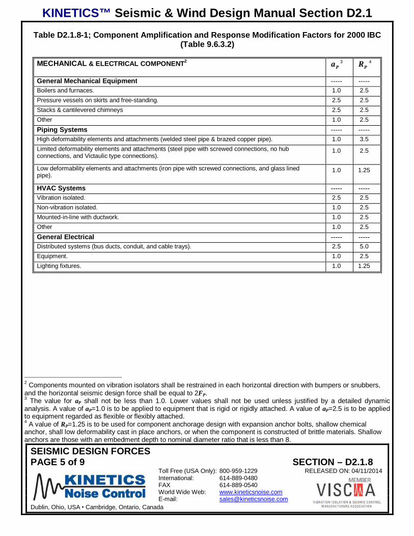
KINETICS™ Seismic & Wind Design Manual Section D2.1
SEISMIC DESIGN FORCESPAGE 5 of 9 SECTION – D2.1.8
Toll Free (USA Only): 800-959-1229 RELEASED ON: 04/11/2014International: 614-889-0480FAX 614-889-0540World Wide Web: www.kineticsnoise.comE-mail: [email protected]
Dublin, Ohio, USA Cambridge, Ontario, Canada
Table D2.1.8-1; Component Amplification and Response Modification Factors for 2000 IBC(Table 9.6.3.2)
MECHANICAL & ELECTRICAL COMPONENT2Pa 3
PR 4
General Mechanical Equipment ----- -----Boilers and furnaces. 1.0 2.5Pressure vessels on skirts and free-standing. 2.5 2.5Stacks & cantilevered chimneys 2.5 2.5Other 1.0 2.5Piping Systems ----- -----High deformability elements and attachments (welded steel pipe & brazed copper pipe). 1.0 3.5Limited deformability elements and attachments (steel pipe with screwed connections, no hubconnections, and Victaulic type connections).
1.0 2.5
Low deformability elements and attachments (iron pipe with screwed connections, and glass linedpipe).
1.0 1.25
HVAC Systems ----- -----Vibration isolated. 2.5 2.5Non-vibration isolated. 1.0 2.5Mounted-in-line with ductwork. 1.0 2.5Other 1.0 2.5General Electrical ----- -----Distributed systems (bus ducts, conduit, and cable trays). 2.5 5.0Equipment. 1.0 2.5Lighting fixtures. 1.0 1.25
2 Components mounted on vibration isolators shall be restrained in each horizontal direction with bumpers or snubbers,and the horizontal seismic design force shall be equal to 2FP.3 The value for aP shall not be less than 1.0. Lower values shall not be used unless justified by a detailed dynamicanalysis. A value of aP=1.0 is to be applied to equipment that is rigid or rigidly attached. A value of aP=2.5 is to be appliedto equipment regarded as flexible or flexibly attached.4 A value of RP=1.25 is to be used for component anchorage design with expansion anchor bolts, shallow chemicalanchor, shall low deformability cast in place anchors, or when the component is constructed of brittle materials. Shallowanchors are those with an embedment depth to nominal diameter ratio that is less than 8.
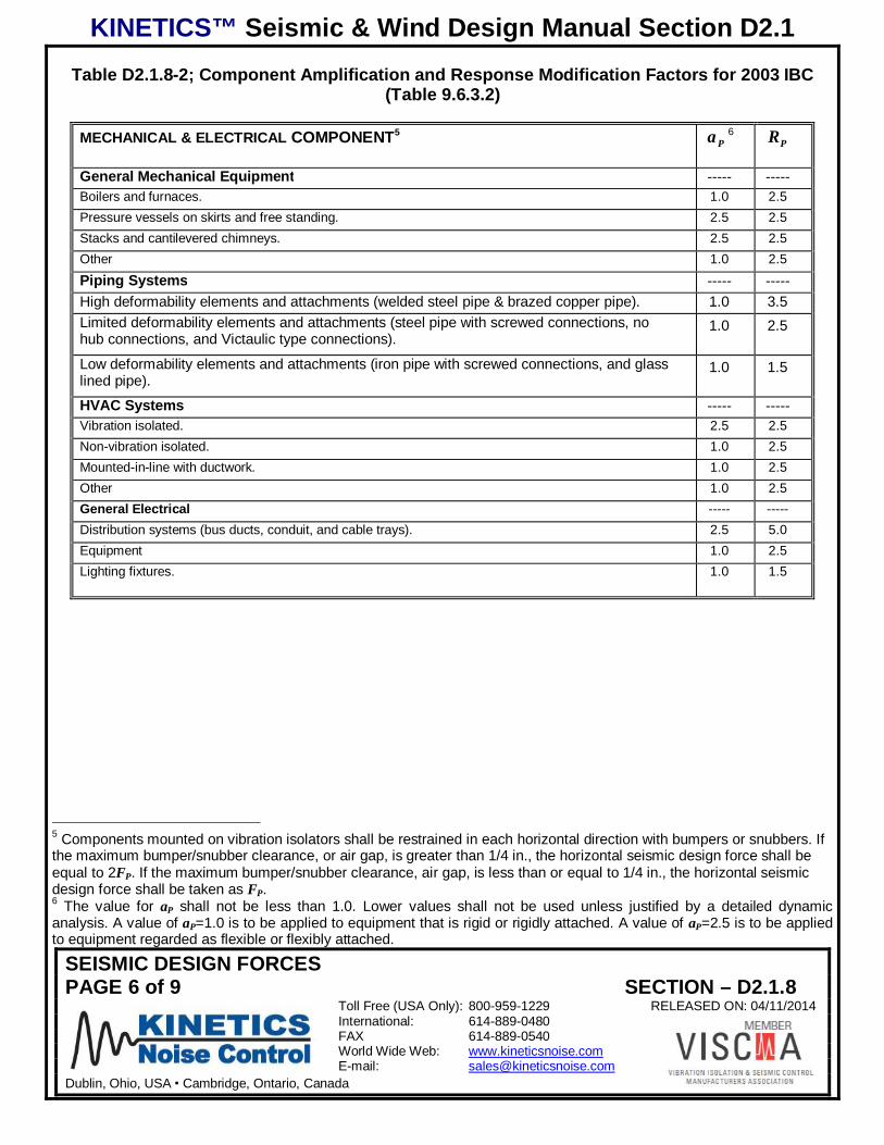
KINETICS™ Seismic & Wind Design Manual Section D2.1
SEISMIC DESIGN FORCESPAGE 6 of 9 SECTION – D2.1.8
Toll Free (USA Only): 800-959-1229 RELEASED ON: 04/11/2014International: 614-889-0480FAX 614-889-0540World Wide Web: www.kineticsnoise.comE-mail: [email protected]
Dublin, Ohio, USA Cambridge, Ontario, Canada
Table D2.1.8-2; Component Amplification and Response Modification Factors for 2003 IBC(Table 9.6.3.2)
MECHANICAL & ELECTRICAL COMPONENT5Pa 6
PR
General Mechanical Equipment ----- -----Boilers and furnaces. 1.0 2.5Pressure vessels on skirts and free standing. 2.5 2.5Stacks and cantilevered chimneys. 2.5 2.5Other 1.0 2.5Piping Systems ----- -----High deformability elements and attachments (welded steel pipe & brazed copper pipe). 1.0 3.5Limited deformability elements and attachments (steel pipe with screwed connections, nohub connections, and Victaulic type connections).
1.0 2.5
Low deformability elements and attachments (iron pipe with screwed connections, and glasslined pipe).
1.0 1.5
HVAC Systems ----- -----Vibration isolated. 2.5 2.5Non-vibration isolated. 1.0 2.5Mounted-in-line with ductwork. 1.0 2.5Other 1.0 2.5General Electrical ----- -----Distribution systems (bus ducts, conduit, and cable trays). 2.5 5.0Equipment 1.0 2.5Lighting fixtures. 1.0 1.5
5 Components mounted on vibration isolators shall be restrained in each horizontal direction with bumpers or snubbers. Ifthe maximum bumper/snubber clearance, or air gap, is greater than 1/4 in., the horizontal seismic design force shall beequal to 2FP. If the maximum bumper/snubber clearance, air gap, is less than or equal to 1/4 in., the horizontal seismicdesign force shall be taken as FP.6 The value for aP shall not be less than 1.0. Lower values shall not be used unless justified by a detailed dynamicanalysis. A value of aP=1.0 is to be applied to equipment that is rigid or rigidly attached. A value of aP=2.5 is to be appliedto equipment regarded as flexible or flexibly attached.
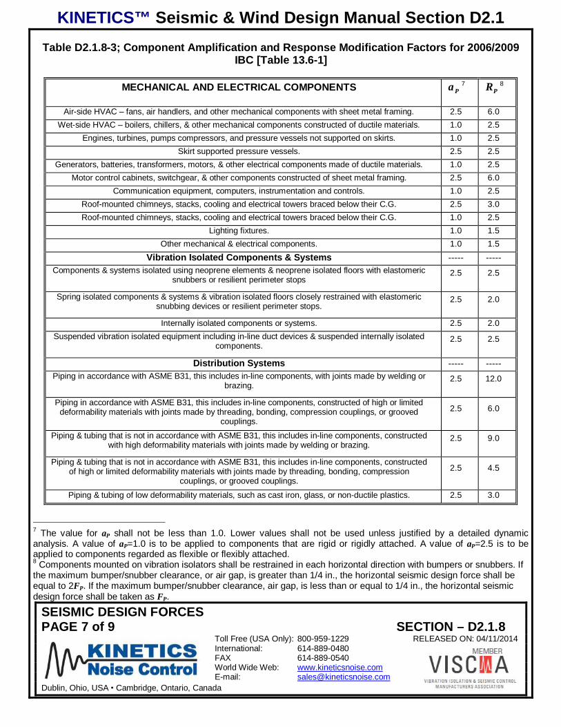
KINETICS™ Seismic & Wind Design Manual Section D2.1
SEISMIC DESIGN FORCESPAGE 7 of 9 SECTION – D2.1.8
Toll Free (USA Only): 800-959-1229 RELEASED ON: 04/11/2014International: 614-889-0480FAX 614-889-0540World Wide Web: www.kineticsnoise.comE-mail: [email protected]
Dublin, Ohio, USA Cambridge, Ontario, Canada
Table D2.1.8-3; Component Amplification and Response Modification Factors for 2006/2009IBC [Table 13.6-1]
MECHANICAL AND ELECTRICAL COMPONENTS Pa 7PR 8
Air-side HVAC – fans, air handlers, and other mechanical components with sheet metal framing. 2.5 6.0Wet-side HVAC – boilers, chillers, & other mechanical components constructed of ductile materials. 1.0 2.5
Engines, turbines, pumps compressors, and pressure vessels not supported on skirts. 1.0 2.5Skirt supported pressure vessels. 2.5 2.5
Generators, batteries, transformers, motors, & other electrical components made of ductile materials. 1.0 2.5Motor control cabinets, switchgear, & other components constructed of sheet metal framing. 2.5 6.0
Communication equipment, computers, instrumentation and controls. 1.0 2.5Roof-mounted chimneys, stacks, cooling and electrical towers braced below their C.G. 2.5 3.0Roof-mounted chimneys, stacks, cooling and electrical towers braced below their C.G. 1.0 2.5
Lighting fixtures. 1.0 1.5Other mechanical & electrical components. 1.0 1.5
Vibration Isolated Components & Systems ----- -----Components & systems isolated using neoprene elements & neoprene isolated floors with elastomeric
snubbers or resilient perimeter stops2.5 2.5
Spring isolated components & systems & vibration isolated floors closely restrained with elastomericsnubbing devices or resilient perimeter stops.
2.5 2.0
Internally isolated components or systems. 2.5 2.0Suspended vibration isolated equipment including in-line duct devices & suspended internally isolated
components.2.5 2.5
Distribution Systems ----- -----Piping in accordance with ASME B31, this includes in-line components, with joints made by welding or
brazing.2.5 12.0
Piping in accordance with ASME B31, this includes in-line components, constructed of high or limiteddeformability materials with joints made by threading, bonding, compression couplings, or grooved
couplings.2.5 6.0
Piping & tubing that is not in accordance with ASME B31, this includes in-line components, constructedwith high deformability materials with joints made by welding or brazing.
2.5 9.0
Piping & tubing that is not in accordance with ASME B31, this includes in-line components, constructedof high or limited deformability materials with joints made by threading, bonding, compression
couplings, or grooved couplings.2.5 4.5
Piping & tubing of low deformability materials, such as cast iron, glass, or non-ductile plastics. 2.5 3.0
7 The value for aP shall not be less than 1.0. Lower values shall not be used unless justified by a detailed dynamicanalysis. A value of aP=1.0 is to be applied to components that are rigid or rigidly attached. A value of aP=2.5 is to beapplied to components regarded as flexible or flexibly attached.8 Components mounted on vibration isolators shall be restrained in each horizontal direction with bumpers or snubbers. Ifthe maximum bumper/snubber clearance, or air gap, is greater than 1/4 in., the horizontal seismic design force shall beequal to 2FP. If the maximum bumper/snubber clearance, air gap, is less than or equal to 1/4 in., the horizontal seismicdesign force shall be taken as FP.

KINETICS™ Seismic & Wind Design Manual Section D2.1
SEISMIC DESIGN FORCESPAGE 8 of 9 SECTION – D2.1.8
Toll Free (USA Only): 800-959-1229 RELEASED ON: 04/11/2014International: 614-889-0480FAX 614-889-0540World Wide Web: www.kineticsnoise.comE-mail: [email protected]
Dublin, Ohio, USA Cambridge, Ontario, Canada
Ductwork, including in-line components, constructed of high deformability materials, with joints made bywelding or brazing.
2.5 9.0
Ductwork, including in-line components, constructed of high or limited deformability materials, withjoints made by means other than welding or brazing.
2.5 6.0
Duct work constructed of low deformability materials such as cast iron, glass, or non-ductile plastics. 2.5 3.0Electrical conduit, bus ducts, rigidly mounted cable trays, & plumbing. 1.0 2.5
Suspended cable trays. 2.5 6.0
Table D2.1.8-4; Component Amplification and Response Modification Factors for 2012 IBC{Table 13.6-1}
MECHANICAL AND ELECTRICAL COMPONENTS Pa 9PR 10
Air-side HVAC – fans, air handlers, and other mechanical components with sheet metal framing. 2.5 6.0Wet-side HVAC – boilers, chillers, & other mechanical components constructed of ductile materials. 1.0 2.5
Engines, turbines, pumps compressors, and pressure vessels not supported on skirts. 1.0 2.5Skirt supported pressure vessels. 2.5 2.5
Generators, batteries, transformers, motors, & other electrical components made of ductile materials. 1.0 2.5Motor control cabinets, switchgear, & other components constructed of sheet metal framing. 2.5 6.0
Communication equipment, computers, instrumentation and controls. 1.0 2.5Roof-mounted chimneys, stacks, cooling and electrical towers braced below their C.G. 2.5 3.0Roof-mounted chimneys, stacks, cooling and electrical towers braced below their C.G. 1.0 2.5
Lighting fixtures. 1.0 1.5Other mechanical & electrical components. 1.0 1.5
Vibration Isolated Components & Systems ----- -----Components & systems isolated using neoprene elements & neoprene isolated floors with elastomeric
snubbers or resilient perimeter stops2.5 2.5
Spring isolated components & systems & vibration isolated floors closely restrained with elastomericsnubbing devices or resilient perimeter stops.
2.5 2.0
Internally isolated components or systems. 2.5 2.0Suspended vibration isolated equipment including in-line duct devices & suspended internally isolated
components.2.5 2.5
9 The value for aP shall not be less than 1.0. Lower values shall not be used unless justified by a detailed dynamicanalysis. A value of aP=1.0 is to be applied to components that are rigid or rigidly attached. A value of aP=2.5 is to beapplied to components regarded as flexible or flexibly attached.10 Components mounted on vibration isolators shall be restrained in each horizontal direction with bumpers or snubbers. Ifthe maximum bumper/snubber clearance, or air gap, is greater than 1/4 in., the horizontal seismic design force shall beequal to 2FP. If the maximum bumper/snubber clearance, air gap, is less than or equal to 1/4 in., the horizontal seismicdesign force shall be taken as FP.
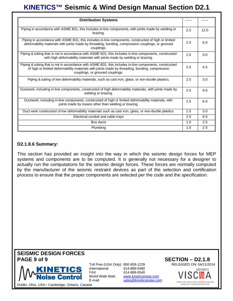
KINETICS™ Seismic & Wind Design Manual Section D2.1
SEISMIC DESIGN FORCESPAGE 9 of 9 SECTION – D2.1.8
Toll Free (USA Only): 800-959-1229 RELEASED ON: 04/11/2014International: 614-889-0480FAX 614-889-0540World Wide Web: www.kineticsnoise.comE-mail: [email protected]
Dublin, Ohio, USA Cambridge, Ontario, Canada
Distribution Systems ----- -----
Piping in accordance with ASME B31, this includes in-line components, with joints made by welding orbrazing.
2.5 12.0
Piping in accordance with ASME B31, this includes in-line components, constructed of high or limiteddeformability materials with joints made by threading, bonding, compression couplings, or grooved
couplings.2.5 6.0
Piping & tubing that is not in accordance with ASME B31, this includes in-line components, constructedwith high deformability materials with joints made by welding or brazing.
2.5 9.0
Piping & tubing that is not in accordance with ASME B31, this includes in-line components, constructedof high or limited deformability materials with joints made by threading, bonding, compression
couplings, or grooved couplings.2.5 4.5
Piping & tubing of low deformability materials, such as cast iron, glass, or non-ductile plastics. 2.5 3.0
Ductwork, including in-line components, constructed of high deformability materials, with joints made bywelding or brazing.
2.5 9.0
Ductwork, including in-line components, constructed of high or limited deformability materials, withjoints made by means other than welding or brazing.
2.5 6.0
Duct work constructed of low deformability materials such as cast iron, glass, or non-ductile plastics. 2.5 3.0Electrical conduit and cable trays 2.5 6.0
Bus ducts 1.0 2.5Plumbing 1.0 2.5
D2.1.8.6 Summary:
This section has provided an insight into the way in which the seismic design forces for MEPsystems and components are to be computed. It is generally not necessary for a designer toactually run the computations for the seismic design forces. These forces are normally computedby the manufacturer of the seismic restraint devices as part of the selection and certificationprocess to ensure that the proper components are selected per the code and the specification.

KINETICS™ Seismic & Wind Design Manual Section D2.1
ANCHORAGE OF MEP COMPONENTS TO THE BUILDING STRUCTUREPAGE 1 of 5 SECTION – D2.1.9
Toll Free (USA Only): 800-959-1229 RELEASED ON: 04/11/2014International: 614-889-0480FAX 614-889-0540World Wide Web: www.kineticsnoise.comE-mail: [email protected]
Dublin, Ohio, USA Cambridge, Ontario, Canada
ANCHORAGE OF MEP COMPONENTS TO THE BUILDING STRUCTURE
D2.1.9.1 Introduction:
The anchorage, or attachment, of the MEP components and their seismic restraints to the buildingstructure has always been a gray area generally left to the installing contractor with little or noguidance from the design professionals responsible for the MEP systems or the building structure.ASCE 7 does give some general guidance for the making these attachments. However, thedesign professionals involved with the MEP systems and the building structure must share theresponsibility for ensuring the adequacy of these attachments. This section will cover the guidanceprovided to the design professionals of record in ASCE 7.
D2.1.9.2 General Guidelines for MEP Component Anchorage (Section 9.6.1.6 and 9.6.3.4)[Section 13.4] {Section 13.4 and Section 13.4.1}1:
1. The MEP component, its supports, and seismic restraints must be positively attached to thebuilding structure without relying on frictional resistance generated by the dead weight of thecomponent. The following are some of the acceptable ways and means of attachment.
a. Bolting
b. Welding
c. Post installed concrete anchors
d. Cast in place concrete anchors
2. There must be a continuous load path of sufficient strength and stiffness between thecomponent and the building structure to withstand the expected seismic loads anddisplacements. This means that when cable restraints are used for distributed MEP systems,the cables can not bend or wrap around any other component or structure in a straight linepath between the component and the structure.
3. The local areas of the building structure must be designed with sufficient strength andstiffness to resist and transfer the seismic restraint forces from the MEP systems andcomponents to the main force resisting structure of the building. It is at this point that thedesign professional of record, and the installing contractor for the MEP system must workclosely with the structural engineer of record to make sure that the intended anchoragepoints for the MEP system seismic restraints have sufficient capacity.
1 References in brackets (Sections 9.6.1.6 and 9.6.3.4) [Section 13.4] {Section 13.4} apply to sections, tables, and/orequations in ASCE 7-98/02, ASCE 7-05, and ASCE 7-10 respectively which forms the basis for the seismic provisions in2000/2003 IBC, 2006/2009 IBC, and 2012 IBC respectively.
KINETICS™ Seismic & Wind Design Manual Section D2.1
ANCHORAGE OF MEP COMPONENTS TO THE BUILDING STRUCTUREPAGE 2 of 5 SECTION – D2.1.9
Toll Free (USA Only): 800-959-1229 RELEASED ON: 04/11/2014International: 614-889-0480FAX 614-889-0540World Wide Web: www.kineticsnoise.comE-mail: [email protected]
Dublin, Ohio, USA Cambridge, Ontario, Canada
Special Notes:
1. The design documents need to contain enough information pertaining to theattachments to allow a design professional to verify the compliance with the code.
2. In ASCE 7-10 Section 13.4.1, the design forces and displacements are to bedetermined according to Sections 13.3.1 and 13.3.2 as in previous versions exceptthat 06.RP . Thus, the design forces for certain pipe and duct systems will be higherthan what would be indicated from using the PR values found in Table 13.6-1of ASCE 7-10.
D2.1.9.3 Anchorage in (Cracked) Concrete and Masonry (Section 9.6.1.6) [Section 13.4.2]{Section 13.4.2.1 and Section 13.4.2.3}:
1. Anchors for MEP component seismic restraints and supports are to be designed andproportioned to carry the least of the following:
a. A force equal to 1.3 times the seismic design forces acting on the component and itssupports and restraints.
b. The maximum force that can be transferred to the anchor by the component and itssupports.
2. 5.1PR will be used to determine the component forces unless:
a. The design anchorage of the component and/or its restraints is governed by thestrength of a ductile steel element.
b. The design of post installed anchors in concrete used for the anchorage of thecomponent supports and restraints is prequalified for seismic applications according toACI 355.2.
i. Anchors that have been prequalified per AC 1932 (ACI 355.2) will have an ICC-ES ESR Report issued for that anchor stating the fact that it is suitable forseismic applications for the current version of IBC. It will also give the allowableloads, embedments, and edge distances pertinent to the allowable loads.
ii. Anchors from different manufacturers may not be directly substituted on a one-to-one basis. Each manufacturer will have a different design that will havedifferent allowable loads when tested under AC 193 (ACI 355.2). The allowableloads for equivalent anchor sizes may be radically different.
2 AC 193 is the Acceptance Criteria used by ICC ES to evaluate and pre-qualify the concrete anchors for use in crackedconcrete. It is base directly on ACI 355.2.
KINETICS™ Seismic & Wind Design Manual Section D2.1
ANCHORAGE OF MEP COMPONENTS TO THE BUILDING STRUCTUREPAGE 3 of 5 SECTION – D2.1.9
Toll Free (USA Only): 800-959-1229 RELEASED ON: 04/11/2014International: 614-889-0480FAX 614-889-0540World Wide Web: www.kineticsnoise.comE-mail: [email protected]
Dublin, Ohio, USA Cambridge, Ontario, Canada
c. The anchor is designed in accordance with Section 14.2.2.14 of ASCE 7-05.
For 2000 IBC, ASCE 7-98, the “cracked” concrete anchors are not required, and standard postinstalled wedge type anchors may be used for seismic restraint as long as there is an ICC Legacyreport stating that the anchors may be used in seismic applications. For 2003 IBC, ASCE 7-02,there are no specific statements in ASCE 7-02 that require the use of “cracked” concrete anchorsin seismic applications. However, ASCE 7-02 Section 9.9 adopts ACI 318-02 as a referencedocument. ACI 318-02 specifies that the post installed anchors meet ACI 355.2 and “are requiredto be qualified for moderate or high seismic risk zone usage.” ACI 355.2 is the test standard bywhich post installed anchors are to be pre-qualified for seismic applications in cracked concrete.So, by inference, “cracked” concrete anchors should also be used for 2003 IBC. However, thathas not yet been widely enforced since few if any post installed anchors had been qualified to thisstandard before 2006/2009 IBC was issued.
There are new and special wrinkles for concrete anchors in ASCE 7-10 which will be picked up by2012 IBC. ASCE 7-10 Section 13.4.2.1 requires the concrete anchors to be designed per ACI 318Appendix D. ACI 318-08 Section D.3.3.4 specifies that the anchors must be designed such thattheir failure is to be governed by a ductile steel element. So, the ductile steel element needs to failbefore the concrete fails. The intent of the code is to prevent an unpredictable brittle failure in theconcrete by having a predictable ductile failure in the steel of the anchor. There is an alternative tothis requirement in ACI 318-08 Section D.3.3.6 which requires that, instead of the ductile failure inthe steel of the anchor, that the allowable strength of the anchors may be reduced by 60%. Thiswill create problems throughout the industry for MEP contractors who must use post installedconcrete anchors to attach the restraints for MEP components to the building structure becausethe standard offering of wedge type anchors, typically, do not meet the ductility requirement of thecode. To meet the requirement of the code, the steel element must have an elongation of at least14% and a reduction in area of at least 30%. It may be possible to achieve this with adhesive typepost installed anchors, but not in all cases. The result is that more anchors will be required toattach the restraints to the building than before. This means more “real estate” will be required foreach anchor point.
Masonry anchors are now discussed more fully in ASCE 7-10 Sections 13.4.2.2 and 13.4.2.3.ASCE 7-10 Section 13.4.2.2 requires that the design of masonry anchors be per TMS 402/ACI503/ASCE5, and that the design be governed by the failure of a ductile steel element or that theallowable strength of the anchor be reduced by 60%. Also, ASCE 7-10 Section 13.4.2.3 requiresthat the anchors used in masonry be prequalified for seismic applications per approvedqualification standards (which do not yet exist). This will cause problems with application andinspection when 2012 IBC is implemented. There will be no acceptance criteria for pre-qualifyinganchors for seismic applications in masonry, and thus, no pre-qualified anchors with an ICC-ESR.
D2.1.9.4 Undercut Anchors (Section 9.6.3.13.2-c) [Section 13.6.5.5-5] {Section 13.6.5.5-5}:
For both 2000 IBC, ASCE 7-98, and 2006/2009 IBC, ASCE 7-05, post installed expansion, wedge,anchors may not be used for non-vibration isolated mechanical equipment rated over 10 hp (7.45
KINETICS™ Seismic & Wind Design Manual Section D2.1
ANCHORAGE OF MEP COMPONENTS TO THE BUILDING STRUCTUREPAGE 4 of 5 SECTION – D2.1.9
Toll Free (USA Only): 800-959-1229 RELEASED ON: 04/11/2014International: 614-889-0480FAX 614-889-0540World Wide Web: www.kineticsnoise.comE-mail: [email protected]
Dublin, Ohio, USA Cambridge, Ontario, Canada
kW). However, post installed undercut expansion anchors may be used. Also, because they arenot specifically prohibited, adhesive anchors may be used.
For 2003 IBC, ASCE 7-02, post installed expansion, wedge, anchors may not be used for non-vibration isolated mechanical equipment. However, post installed undercut expansion anchors arepermitted. Again, adhesive anchors may be used because they are not specifically prohibited.
ASCE 7-10 Section 13.6.5.5-5 simply states that anchors used for non-vibration isolatedequipment rated over 10 Hp (7.45 kW) are to be qualified per ACI 355.2 (AC 193). Therequirement for undercut wedge anchors is removed.
D2.1.9.5 Prying of Bolts and Anchors (Section 9.6.1.6.3) [Section 13.4.3] {Section 13.4.3}:
The design of the attachment of the MEP component supports and restraints must take intoaccount the mounting conditions such as eccentricity in the supports and brackets, and prying ofthe bolts or anchors.
D2.1.9.6 Power Actuated or Driven Fasteners (Section 9.6.1.6.5) [Section 13.4.5] {Section13.4.5}:
Power actuated or driven fasteners, such as powder shot pins, may not be used for tensile loadapplications in Seismic Design Categories D, E, and F unless specifically approved for thisapplication.
The language in ASCE 7-10 Section 13.4.5 has been made more restrictive. Power actuatedfasteners in concrete or steel are not to be used sustained tension loads or brace (seismicrestraint) applications in Seismic Design Categories D, E, or F unless they have been approvedfor seismic applications. Power actuated fasteners are not to be used in masonry unless approvedfor seismic applications.
D2.1.9.7 Friction Clips (Section 9.6.3.13.2-b) [Section 13.4.6] {Section 13.4.6}:
Friction clips may not be used to attach seismic restraints to the component or the buildingstructure. A typical example would be the attachment of a cable restraint to a structural beam witha standard beam clamp. A beam clamp with a restraint strap or safety strap, capable of resistingthe applied seismic load that will ensure that the clamp will be prevented from walking off thebeam may be used.
ASCE 7-10 Section 13.4.6 has clarified the application of friction type clips for attaching seismicrestraints to the building structure. They are not to be used for supporting sustained loads as wellas seismic loads in Seismic Design Categories D, E, or F. The implication is that they can be usedfor seismic loads alone. C-type beam and large flange clamps can be used for hangers if they areequipped with safety straps. In all cases the bolts providing the clamping force that generates thefriction load must be equipped with lock nuts or the equivalent to prevent the loosening of thethreaded connections.
KINETICS™ Seismic & Wind Design Manual Section D2.1
ANCHORAGE OF MEP COMPONENTS TO THE BUILDING STRUCTUREPAGE 5 of 5 SECTION – D2.1.9
Toll Free (USA Only): 800-959-1229 RELEASED ON: 04/11/2014International: 614-889-0480FAX 614-889-0540World Wide Web: www.kineticsnoise.comE-mail: [email protected]
Dublin, Ohio, USA Cambridge, Ontario, Canada
D2.1.9.8 Summary:
Attachment of the MEP components and their seismic restraints to the building structure is of theutmost importance to maintaining the building function following an earthquake. It is theresponsibility of the design professionals of record for the MEP systems to work with the structuralengineer of record and the architect of record for the building to ensure that the anchorage pointsfor the MEP component supports and restraints have been properly designed to transfer thedesign seismic loads as well as any other dead weight and service loads.

KINETICS™ Seismic & Wind Design Manual Section D2.2.1
INTRODUCTIONPAGE 1 of 2 SECTION – D2.2.1
Toll Free (USA Only): 800-959-1229 RELEASED ON: 04/11/2014International: 614-889-0480FAX 614-889-0540World Wide Web: www.kineticsnoise.comE-mail: [email protected]
Dublin, Ohio, USA Cambridge, Ontario, Canada
IBC Wind
D2.2.1 - Introduction:
The need for the seismic restraint of equipment has been well recognized for many years. It evenappears in most specifications. The need for the wind restraint of exposed roof top equipment,however, has been largely ignored. It very seldom appears as a specification item, and when itdoes it is placed in an obscure portion of the specification, almost as an after thought. HurricaneKatrina and the other recent hurricanes in Florida and the Gulf of Mexico have focused FEMA’sattention on the ability of roof top equipment to withstand forces generated by high wind events.Of particular interest are the attachments of the equipment to the building structure. This paper willcenter on the different versions of the International Building Code (IBC), which are based on thewind provisions of ASCE 7, and how they apply to the wind loads acting on roof top equipment.Table 2.2.1-1 shows the IBC code year along with its ASCE 7 reference version.
Table D2.2.1-1; IBC & ASCE 7 Wind Load References
INTERNATIONALBUILDING CODE
YEAR (IBC)IBC WIND LOAD SECTION ASCE 7 VERSION
ASCE 7 WIND LOADCHAPTER FOR
ROOFTOP EQUIPMENT
2000 1609 98 62003 1609 02 62006 1609 05 62009 1609 05 62012 TBD 10 29
The following references are used throughout Section D2.2
1. 2000 International Building Code; International Code Council, 5203 Leesburg Pike, Suite708, Falls Church, Virginia, 22041-3401; 2000.
2. ASCE 7-98 Minimum Design Loads for Buildings and Other Structures; American Society ofCivil Engineers, 1801 Alexander Bell Drive, Reston, Virginia 20191-4400, Chapter 9.
3. 2003 International Building Code; International Code Council, Inc., 4051 West FlossmoorRoad, Country Club Hills, Illinois 60478-5795; 2002.
4. ASCE/SEI 7-02 Minimum Design Loads for Buildings and Other Structures; AmericanSociety of Civil Engineers, 1801 Alexander Bell Drive, Reston, Virginia 20191-4400, Chapter9.

KINETICS™ Seismic & Wind Design Manual Section D2.2.1
INTRODUCTIONPAGE 2 of 2 SECTION – D2.2.1
Toll Free (USA Only): 800-959-1229 RELEASED ON: 04/11/2014International: 614-889-0480FAX 614-889-0540World Wide Web: www.kineticsnoise.comE-mail: [email protected]
Dublin, Ohio, USA Cambridge, Ontario, Canada
5. 2006 International Building Code; International Code Council, Inc., 4051 West FlossmoorRoad, Country Club Hills, Illinois 60478-5795; 2006.
6. 2009 International Building Code; International Code Council, Inc., 4051 West FlossmoorRoad, Country Club Hills, Illinois 60478-5795; 2009.
7. ASCE/SEI 7-05 Minimum Design Loads for Buildings and Other Structures; AmericanSociety of Civil Engineers, 1801 Alexander Bell Drive, Reston, Virginia 20191-4400,Chapters 1, 2, 11, 13, 20, and 21.
8. 2012 International Building Code; International Code Council, Inc., 4051 West FlossmoorRoad, Country Club Hills, Illinois 60478-5795; Not Yet Published.
9. ASCE/SEI 7-10 Minimum Design Loads for Buildings and Other Structures; AmericanSociety of Civil Engineers, 1801 Alexander Bell Drive, Reston, Virginia 20191-4400; 2010,Chapters 1, 2, 11, 13, 20, 21, 22 and 23.
10. Reinhold, Timothy A.; “Wind Loads and Anchorage Requirements for Rooftop Equipment”;ASHRAE Journal March 2006, www.ashrae.org.
When applying wind restraints to rooftop equipment, it is important to keep the following things inmind.
1. Wind loads are a real and constant threat in all locations in the country.
2. In many cases the wind loads acting on a piece of rooftop equipment will be more severethan the seismic loads.
3. There must be a continuous load path between the rooftop equipment and the buildingstructure.
4. The building structure must be strong enough to carry, not only the dead weight of theequipment, but also carry the design wind loads calculated according to the code provisions.
5. Design calculations and submittals for wind restraints must be forwarded to the StructuralEngineer of Record for evaluation and approval.
6. For curb mounted equipment, not only must the equipment be properly attached to the curb,but the curb itself must be properly attached to the building structure that supports it.
7. The restraint types used for isolated equipment may cause the isolation to be “shorted out”,or ineffective, for extended periods of time during low to moderate wind conditions.
KINETICS™ Seismic & Wind Design Manual Section D2.2.2
CODE OVERVIEW & BASIC INFORMATIONPAGE 1 of 5 SECTION – D2.2.2
Toll Free (USA Only): 800-959-1229 RELEASED ON: 04/11/2014International: 614-889-0480FAX 614-889-0540World Wide Web: www.kineticsnoise.comE-mail: [email protected]
Dublin, Ohio, USA Cambridge, Ontario, Canada
CODE OVERVIEW & BASIC INFORMATION
D2.2.2.1 – Introduction
IBC code years 2000 thru 2009 have been published and are current. IBC 2012 has not yet beenpublished. However, ASCE 7-10 has been published and will, no doubt, form the basis of the windload requirements for IBC 2012. IBC 2000 and 2003, ASCE 7-98 and -02, are, for all intents andpurposes, the same in regards to wind loading. They do not specifically mention equipment, andonly have provisions for horizontal wind loads. IBC 2006, ASCE 7-05, is similar to IBC 2000 and2003, but it does specifically mention equipment in a new section (Section 6.5.15.1), and itrecommends consideration of wind generated uplift forces acting on the equipment in theCommentary (Page 300). IBC 2012 will have entirely new language and structure as pertains towind loads. ASCE 7-10 has broken the wind load section up into 6 new chapters. As seen in TableD2.2.1-1, Chapter 29 deals specifically with roof top equipment. Also, the basic 3 second gustwind speeds are being increased significantly, by 30 mph.
D2.2.2.2 – Wind Restraint for Rooftop Equipment
For all current published versions of the IBC, 2000 thru 2009, Sections 1609.1 and 1609.1.1require that all parts of buildings and structures be designed to withstand the minimum wind loadsprescribed by the version of ASCE 7 that corresponds to the IBC code year in force. Section1609.1 also states that wind loads acting on rooftop equipment may not be reduced through theshielding effects of other structures. These sections of the IBC will impact rooftop equipment in thefollowing ways.
1. It requires that all exposed, outside, equipment and their attachment to the building structurebe designed to resist the code mandated wind loads.
2. Barrier walls, screens, parapets, overhangs, and other shielding structures can not becounted on to protect exposed, outside, equipment. The equipment and its attachments tothe structure must be designed to withstand the full force of the code mandated wind loads.
D2.2.2.3 – Building Classification for Wind Design:
The magnitude of the design wind loads will depend on the classification and use of the building.The basic building classifications have remained the same over the various versions of the IBCand ASCE 7. However, the designations of those classifications have changed over the variousversions of the code. Table D2.2.2-1 shows how the building classifications have changed overthe years, and is based on Table 1-1 of ASCE 7-98/-02, Table 1-1 of ASCE 7-05, and Table 1.5-1of ASCE 7-10.
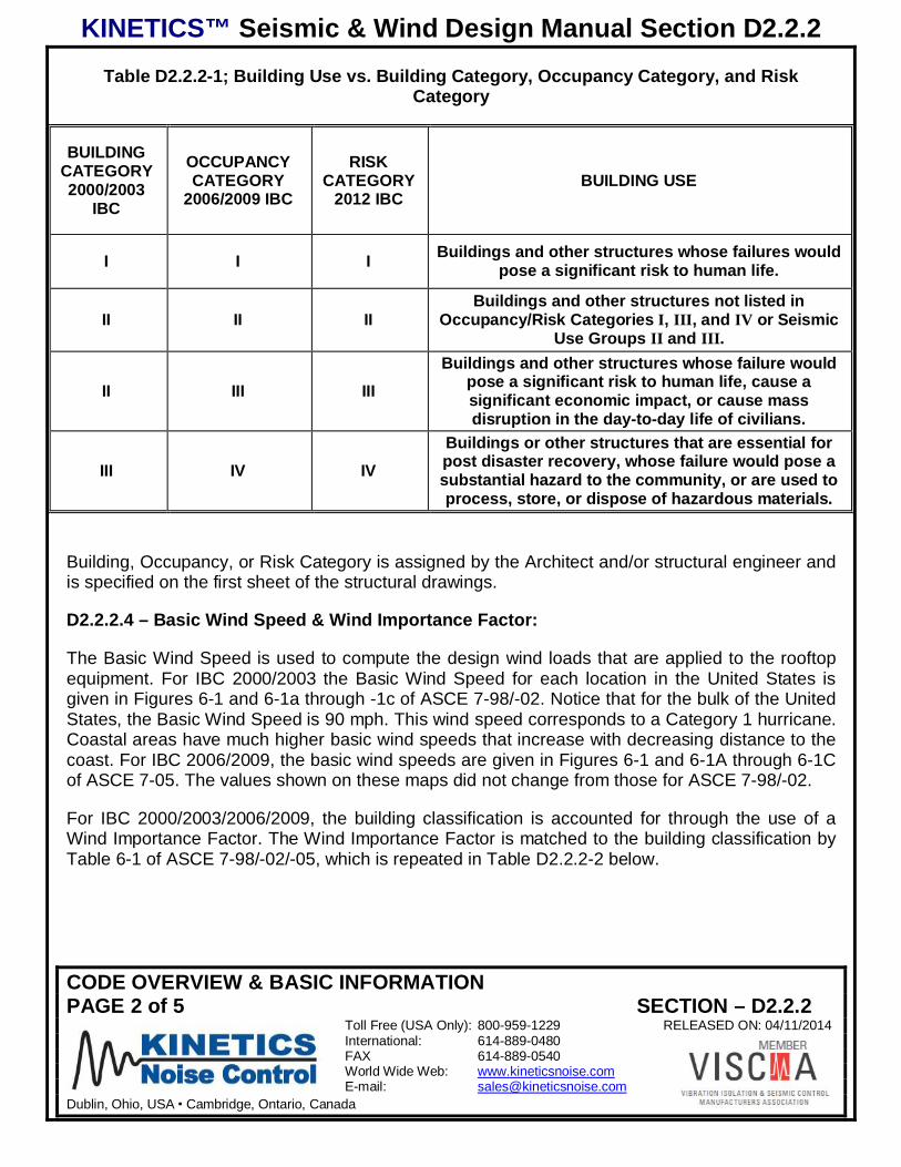
KINETICS™ Seismic & Wind Design Manual Section D2.2.2
CODE OVERVIEW & BASIC INFORMATIONPAGE 2 of 5 SECTION – D2.2.2
Toll Free (USA Only): 800-959-1229 RELEASED ON: 04/11/2014International: 614-889-0480FAX 614-889-0540World Wide Web: www.kineticsnoise.comE-mail: [email protected]
Dublin, Ohio, USA Cambridge, Ontario, Canada
Table D2.2.2-1; Building Use vs. Building Category, Occupancy Category, and RiskCategory
BUILDINGCATEGORY2000/2003
IBC
OCCUPANCYCATEGORY
2006/2009 IBC
RISKCATEGORY
2012 IBCBUILDING USE
I I I Buildings and other structures whose failures wouldpose a significant risk to human life.
II II IIBuildings and other structures not listed in
Occupancy/Risk Categories I, III, and IV or SeismicUse Groups II and III.
II III IIIBuildings and other structures whose failure would
pose a significant risk to human life, cause asignificant economic impact, or cause massdisruption in the day-to-day life of civilians.
III IV IVBuildings or other structures that are essential forpost disaster recovery, whose failure would pose asubstantial hazard to the community, or are used toprocess, store, or dispose of hazardous materials.
Building, Occupancy, or Risk Category is assigned by the Architect and/or structural engineer andis specified on the first sheet of the structural drawings.
D2.2.2.4 – Basic Wind Speed & Wind Importance Factor:
The Basic Wind Speed is used to compute the design wind loads that are applied to the rooftopequipment. For IBC 2000/2003 the Basic Wind Speed for each location in the United States isgiven in Figures 6-1 and 6-1a through -1c of ASCE 7-98/-02. Notice that for the bulk of the UnitedStates, the Basic Wind Speed is 90 mph. This wind speed corresponds to a Category 1 hurricane.Coastal areas have much higher basic wind speeds that increase with decreasing distance to thecoast. For IBC 2006/2009, the basic wind speeds are given in Figures 6-1 and 6-1A through 6-1Cof ASCE 7-05. The values shown on these maps did not change from those for ASCE 7-98/-02.
For IBC 2000/2003/2006/2009, the building classification is accounted for through the use of aWind Importance Factor. The Wind Importance Factor is matched to the building classification byTable 6-1 of ASCE 7-98/-02/-05, which is repeated in Table D2.2.2-2 below.
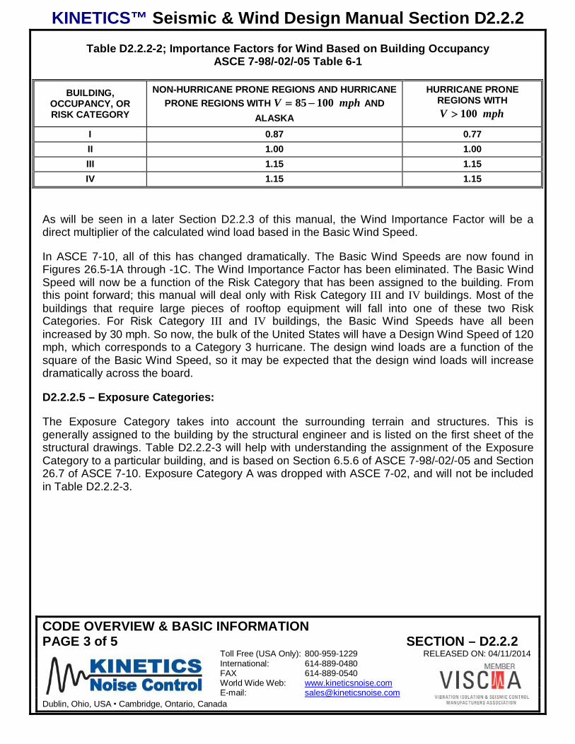
KINETICS™ Seismic & Wind Design Manual Section D2.2.2
CODE OVERVIEW & BASIC INFORMATIONPAGE 3 of 5 SECTION – D2.2.2
Toll Free (USA Only): 800-959-1229 RELEASED ON: 04/11/2014International: 614-889-0480FAX 614-889-0540World Wide Web: www.kineticsnoise.comE-mail: [email protected]
Dublin, Ohio, USA Cambridge, Ontario, Canada
Table D2.2.2-2; Importance Factors for Wind Based on Building OccupancyASCE 7-98/-02/-05 Table 6-1
BUILDING,OCCUPANCY, ORRISK CATEGORY
NON-HURRICANE PRONE REGIONS AND HURRICANEPRONE REGIONS WITH mphV 10085 AND
ALASKA
HURRICANE PRONEREGIONS WITH
mphV 100
I 0.87 0.77II 1.00 1.00III 1.15 1.15IV 1.15 1.15
As will be seen in a later Section D2.2.3 of this manual, the Wind Importance Factor will be adirect multiplier of the calculated wind load based in the Basic Wind Speed.
In ASCE 7-10, all of this has changed dramatically. The Basic Wind Speeds are now found inFigures 26.5-1A through -1C. The Wind Importance Factor has been eliminated. The Basic WindSpeed will now be a function of the Risk Category that has been assigned to the building. Fromthis point forward; this manual will deal only with Risk Category III and IV buildings. Most of thebuildings that require large pieces of rooftop equipment will fall into one of these two RiskCategories. For Risk Category III and IV buildings, the Basic Wind Speeds have all beenincreased by 30 mph. So now, the bulk of the United States will have a Design Wind Speed of 120mph, which corresponds to a Category 3 hurricane. The design wind loads are a function of thesquare of the Basic Wind Speed, so it may be expected that the design wind loads will increasedramatically across the board.
D2.2.2.5 – Exposure Categories:
The Exposure Category takes into account the surrounding terrain and structures. This isgenerally assigned to the building by the structural engineer and is listed on the first sheet of thestructural drawings. Table D2.2.2-3 will help with understanding the assignment of the ExposureCategory to a particular building, and is based on Section 6.5.6 of ASCE 7-98/-02/-05 and Section26.7 of ASCE 7-10. Exposure Category A was dropped with ASCE 7-02, and will not be includedin Table D2.2.2-3.
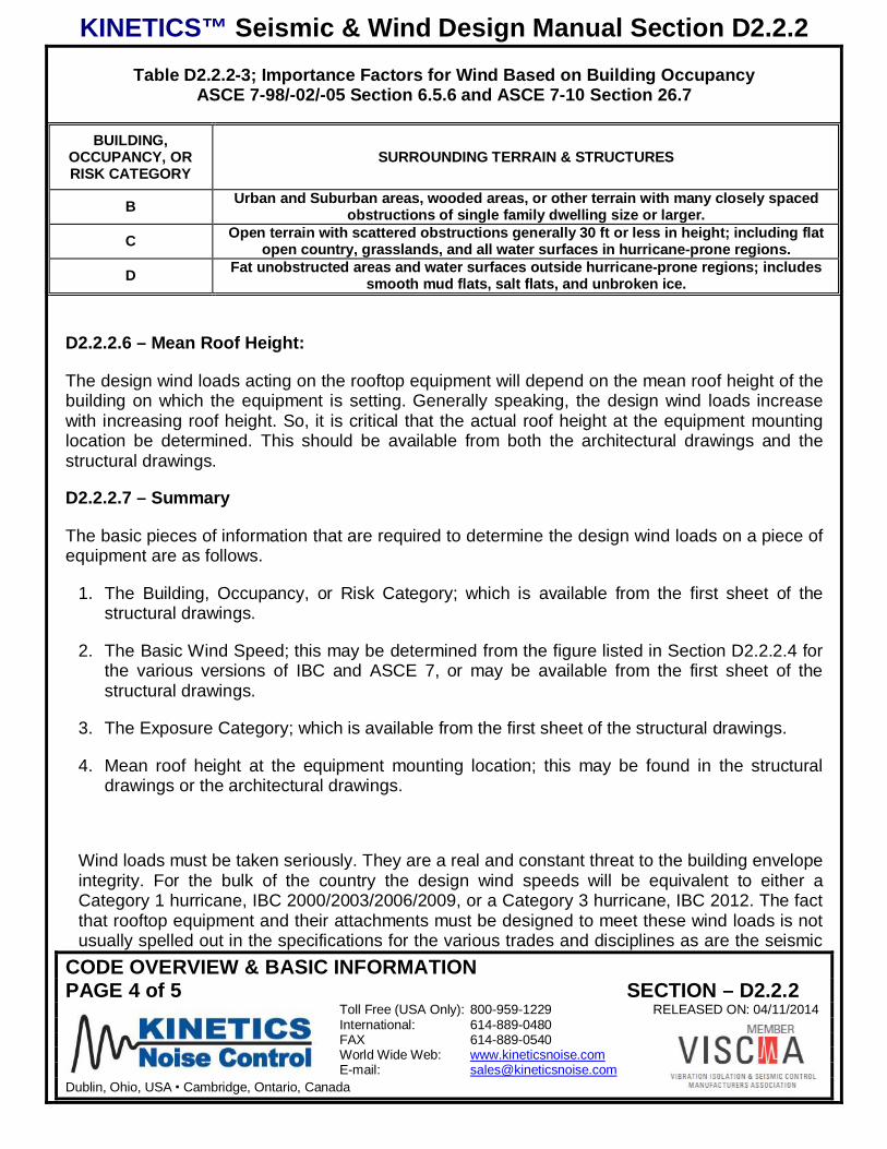
KINETICS™ Seismic & Wind Design Manual Section D2.2.2
CODE OVERVIEW & BASIC INFORMATIONPAGE 4 of 5 SECTION – D2.2.2
Toll Free (USA Only): 800-959-1229 RELEASED ON: 04/11/2014International: 614-889-0480FAX 614-889-0540World Wide Web: www.kineticsnoise.comE-mail: [email protected]
Dublin, Ohio, USA Cambridge, Ontario, Canada
Table D2.2.2-3; Importance Factors for Wind Based on Building OccupancyASCE 7-98/-02/-05 Section 6.5.6 and ASCE 7-10 Section 26.7
BUILDING,OCCUPANCY, ORRISK CATEGORY
SURROUNDING TERRAIN & STRUCTURES
B Urban and Suburban areas, wooded areas, or other terrain with many closely spacedobstructions of single family dwelling size or larger.
C Open terrain with scattered obstructions generally 30 ft or less in height; including flatopen country, grasslands, and all water surfaces in hurricane-prone regions.
D Fat unobstructed areas and water surfaces outside hurricane-prone regions; includessmooth mud flats, salt flats, and unbroken ice.
D2.2.2.6 – Mean Roof Height:
The design wind loads acting on the rooftop equipment will depend on the mean roof height of thebuilding on which the equipment is setting. Generally speaking, the design wind loads increasewith increasing roof height. So, it is critical that the actual roof height at the equipment mountinglocation be determined. This should be available from both the architectural drawings and thestructural drawings.
D2.2.2.7 – Summary
The basic pieces of information that are required to determine the design wind loads on a piece ofequipment are as follows.
1. The Building, Occupancy, or Risk Category; which is available from the first sheet of thestructural drawings.
2. The Basic Wind Speed; this may be determined from the figure listed in Section D2.2.2.4 forthe various versions of IBC and ASCE 7, or may be available from the first sheet of thestructural drawings.
3. The Exposure Category; which is available from the first sheet of the structural drawings.
4. Mean roof height at the equipment mounting location; this may be found in the structuraldrawings or the architectural drawings.
Wind loads must be taken seriously. They are a real and constant threat to the building envelopeintegrity. For the bulk of the country the design wind speeds will be equivalent to either aCategory 1 hurricane, IBC 2000/2003/2006/2009, or a Category 3 hurricane, IBC 2012. The factthat rooftop equipment and their attachments must be designed to meet these wind loads is notusually spelled out in the specifications for the various trades and disciplines as are the seismic
KINETICS™ Seismic & Wind Design Manual Section D2.2.2
CODE OVERVIEW & BASIC INFORMATIONPAGE 5 of 5 SECTION – D2.2.2
Toll Free (USA Only): 800-959-1229 RELEASED ON: 04/11/2014International: 614-889-0480FAX 614-889-0540World Wide Web: www.kineticsnoise.comE-mail: [email protected]
Dublin, Ohio, USA Cambridge, Ontario, Canada
design requirements. However, the code does require that rooftop equipment and itsattachments to the building be designed to meet these wind loads.
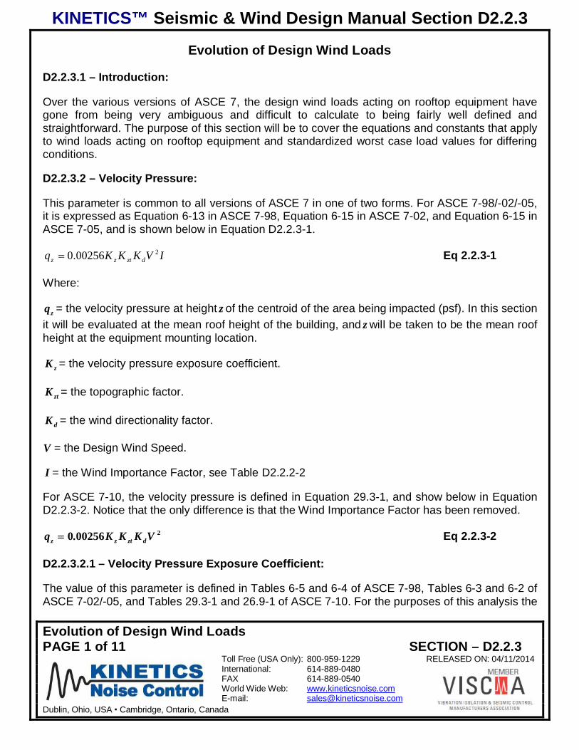
KINETICS™ Seismic & Wind Design Manual Section D2.2.3
Evolution of Design Wind LoadsPAGE 1 of 11 SECTION – D2.2.3
Toll Free (USA Only): 800-959-1229 RELEASED ON: 04/11/2014International: 614-889-0480FAX 614-889-0540World Wide Web: www.kineticsnoise.comE-mail: [email protected]
Dublin, Ohio, USA Cambridge, Ontario, Canada
Evolution of Design Wind Loads
D2.2.3.1 – Introduction:
Over the various versions of ASCE 7, the design wind loads acting on rooftop equipment havegone from being very ambiguous and difficult to calculate to being fairly well defined andstraightforward. The purpose of this section will be to cover the equations and constants that applyto wind loads acting on rooftop equipment and standardized worst case load values for differingconditions.
D2.2.3.2 – Velocity Pressure:
This parameter is common to all versions of ASCE 7 in one of two forms. For ASCE 7-98/-02/-05,it is expressed as Equation 6-13 in ASCE 7-98, Equation 6-15 in ASCE 7-02, and Equation 6-15 inASCE 7-05, and is shown below in Equation D2.2.3-1.
IVKKKq dztzz200256.0 Eq 2.2.3-1
Where:
zq = the velocity pressure at height z of the centroid of the area being impacted (psf). In this sectionit will be evaluated at the mean roof height of the building, and z will be taken to be the mean roofheight at the equipment mounting location.
zK = the velocity pressure exposure coefficient.
ztK = the topographic factor.
dK = the wind directionality factor.
V = the Design Wind Speed.
I = the Wind Importance Factor, see Table D2.2.2-2
For ASCE 7-10, the velocity pressure is defined in Equation 29.3-1, and show below in EquationD2.2.3-2. Notice that the only difference is that the Wind Importance Factor has been removed.
2002560 VKKK.q dztzz Eq 2.2.3-2
D2.2.3.2.1 – Velocity Pressure Exposure Coefficient:
The value of this parameter is defined in Tables 6-5 and 6-4 of ASCE 7-98, Tables 6-3 and 6-2 ofASCE 7-02/-05, and Tables 29.3-1 and 26.9-1 of ASCE 7-10. For the purposes of this analysis the
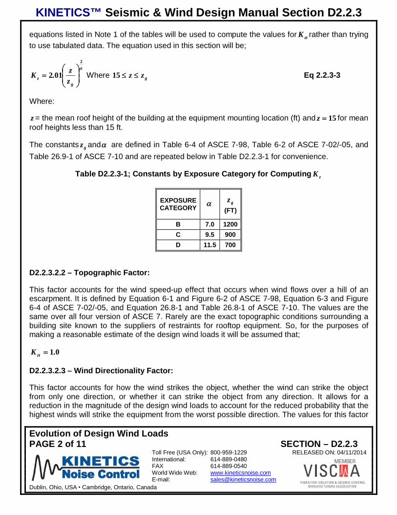
KINETICS™ Seismic & Wind Design Manual Section D2.2.3
Evolution of Design Wind LoadsPAGE 2 of 11 SECTION – D2.2.3
Toll Free (USA Only): 800-959-1229 RELEASED ON: 04/11/2014International: 614-889-0480FAX 614-889-0540World Wide Web: www.kineticsnoise.comE-mail: [email protected]
Dublin, Ohio, USA Cambridge, Ontario, Canada
equations listed in Note 1 of the tables will be used to compute the values for ztK rather than tryingto use tabulated data. The equation used in this section will be;
2
012g
z zz.K Where gzz15 Eq 2.2.3-3
Where:
z = the mean roof height of the building at the equipment mounting location (ft) and 15z for meanroof heights less than 15 ft.
The constants gz and are defined in Table 6-4 of ASCE 7-98, Table 6-2 of ASCE 7-02/-05, andTable 26.9-1 of ASCE 7-10 and are repeated below in Table D2.2.3-1 for convenience.
Table D2.2.3-1; Constants by Exposure Category for Computing zK
EXPOSURECATEGORY
gz(FT)
B 7.0 1200C 9.5 900D 11.5 700
D2.2.3.2.2 – Topographic Factor:
This factor accounts for the wind speed-up effect that occurs when wind flows over a hill of anescarpment. It is defined by Equation 6-1 and Figure 6-2 of ASCE 7-98, Equation 6-3 and Figure6-4 of ASCE 7-02/-05, and Equation 26.8-1 and Table 26.8-1 of ASCE 7-10. The values are thesame over all four version of ASCE 7. Rarely are the exact topographic conditions surrounding abuilding site known to the suppliers of restraints for rooftop equipment. So, for the purposes ofmaking a reasonable estimate of the design wind loads it will be assumed that;
01.K zt
D2.2.3.2.3 – Wind Directionality Factor:
This factor accounts for how the wind strikes the object, whether the wind can strike the objectfrom only one direction, or whether it can strike the object from any direction. It allows for areduction in the magnitude of the design wind loads to account for the reduced probability that thehighest winds will strike the equipment from the worst possible direction. The values for this factor

KINETICS™ Seismic & Wind Design Manual Section D2.2.3
Evolution of Design Wind LoadsPAGE 3 of 11 SECTION – D2.2.3
Toll Free (USA Only): 800-959-1229 RELEASED ON: 04/11/2014International: 614-889-0480FAX 614-889-0540World Wide Web: www.kineticsnoise.comE-mail: [email protected]
Dublin, Ohio, USA Cambridge, Ontario, Canada
are given in Table 6-4 of ASCE 7-98/-05, Table 6-6 of ASCE 7-02, and Table 26.6-1 of ASCE 7-10. Timothy Reinhold in his ASHRAE Journal paper “Wind Loads and Anchorage Requirementsfor Rooftop Equipment”, see Section D2.2.1 of this manual for the reference, recommends that theWind Directionality Factor be given the following Value for rooftop equipment.
850.K d
This is the value given in the ASCE 7 tables listed above that is applied most frequently to objectsthat can be struck by the wind from any direction.
D2.2.3.3 – IBC 2000 & 2003 (ASCE 7-98 & -02):
The equation for the design wind load for ASCE 7-98 and ASCE 7-02 is found in Section 6.5.13which is titled “Design Wind Loads on Open Buildings and Other Structures”. In ASCE 7-98 theequation used is Equation 6-20, and in ASCE 7-02 it is 6-25. Both equations are identical and areshown below.
ffz AGCqF Eq D2.2.3-4
Where:
F = the horizontal design wind load (lbs).
G = the gust effect factor.
fC = the net force coefficient.
fA = the projected area normal to the wind (ft2).
For the purposes of this manual it will be more convenient to express the design wind load as adesign wind pressure. In this way the manual will be more generically applicable. So, thenEquation D2.2.3-4 will have the following form.
fzh GCqp Eq D2.2.3-5
Where:
hp = the horizontal design wind pressure (psf).
D2.2.3.3.1 – Gust Effect Factor:
The gust effect factor takes into account the turbulence and the resilience of the structure, andthere are procedures for calculating the gust effect factor. However, the code provides only one
KINETICS™ Seismic & Wind Design Manual Section D2.2.3
Evolution of Design Wind LoadsPAGE 4 of 11 SECTION – D2.2.3
Toll Free (USA Only): 800-959-1229 RELEASED ON: 04/11/2014International: 614-889-0480FAX 614-889-0540World Wide Web: www.kineticsnoise.comE-mail: [email protected]
Dublin, Ohio, USA Cambridge, Ontario, Canada
value for rigid structures in Section 6.5.8.1 of ASCE 7-98/-02, and this is the value that hastypically been used for rooftop equipment.
850.G
There is some thought that the gust effect factor should be higher than 0.85, say on the order of1.0 or 1.1, for roof top equipment since the equipment is small enough to be completely envelopedby a wind gust. However, there was no research available at the time ASCE 7-02 was publishedto allow a recommendation to be made on an acceptable value for the gust coefficient. Therefore,for ASCE 7-98/-02, the gust coefficient will remain at a value of 0.85.
D2.2.3.3.2 – Net Force Coefficient:
The net force coefficient is determined form Table 6-10 of ASCE 7-98 and Table 6-19 of ASCE 7-02. Most rooftop equipment is square or rectangular. Kinetics Noise Control performs itscalculations with the wind acting on the gross diagonal area. The worst case for a square,rectangular, unit with the wind acting along the diagonal will produce a value for the net forcecoefficient of;
51.C f
This will also cover all of the cases of round rooftop stacks.
D2.2.3.3.3 – Design Wind Pressures for IBC 2000 & 2003:
Table D2.2.3-2 presents horizontal design wind pressures based on the equations and values forthe various coefficients and factors given above. These design wind pressures are for Category IIIand IV buildings where 151.I .
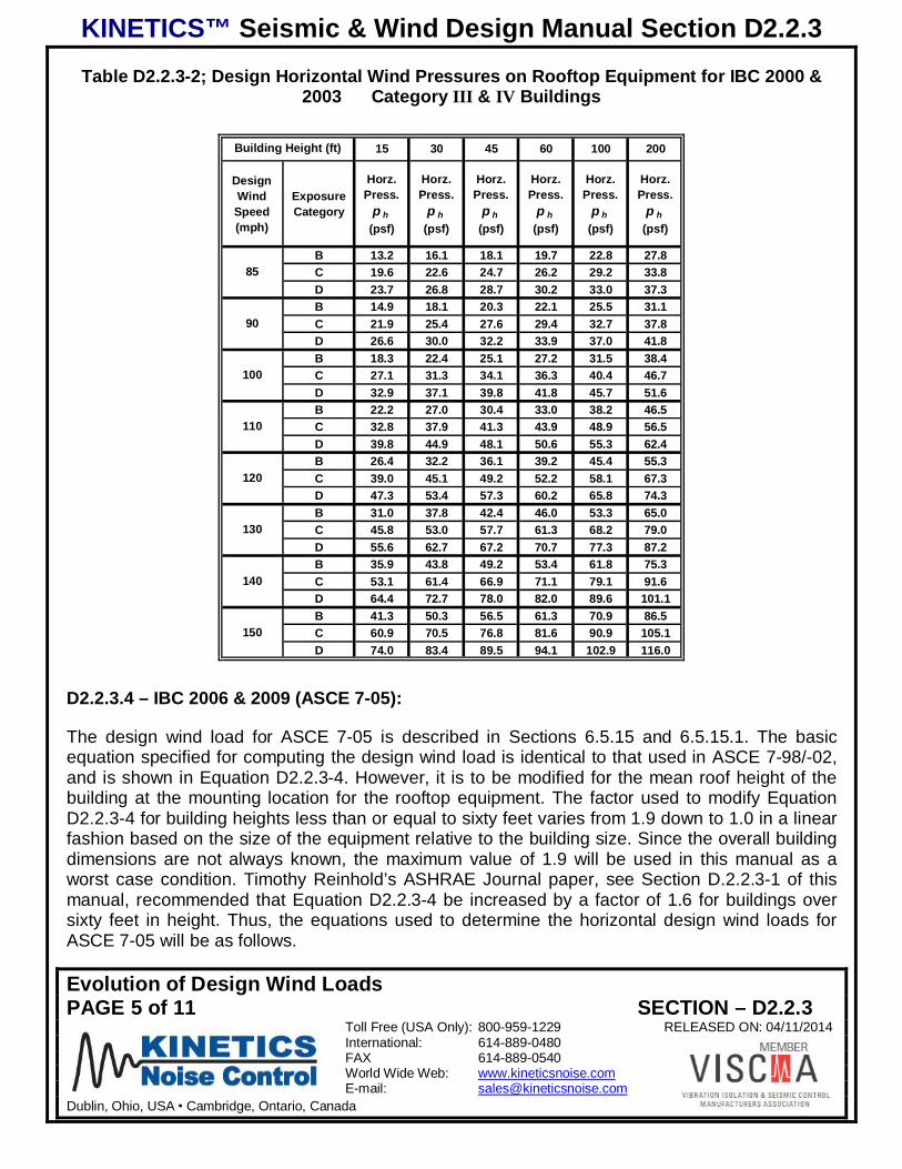
KINETICS™ Seismic & Wind Design Manual Section D2.2.3
Evolution of Design Wind LoadsPAGE 5 of 11 SECTION – D2.2.3
Toll Free (USA Only): 800-959-1229 RELEASED ON: 04/11/2014International: 614-889-0480FAX 614-889-0540World Wide Web: www.kineticsnoise.comE-mail: [email protected]
Dublin, Ohio, USA Cambridge, Ontario, Canada
Table D2.2.3-2; Design Horizontal Wind Pressures on Rooftop Equipment for IBC 2000 &2003 Category III & IV Buildings
15 30 45 60 100 200
DesignWindSpeed(mph)
ExposureCategory
Horz.Press.
p h(psf)
Horz.Press.
p h(psf)
Horz.Press.
p h(psf)
Horz.Press.
p h(psf)
Horz.Press.
p h(psf)
Horz.Press.
p h(psf)
B 13.2 16.1 18.1 19.7 22.8 27.8C 19.6 22.6 24.7 26.2 29.2 33.8D 23.7 26.8 28.7 30.2 33.0 37.3B 14.9 18.1 20.3 22.1 25.5 31.1C 21.9 25.4 27.6 29.4 32.7 37.8D 26.6 30.0 32.2 33.9 37.0 41.8B 18.3 22.4 25.1 27.2 31.5 38.4C 27.1 31.3 34.1 36.3 40.4 46.7D 32.9 37.1 39.8 41.8 45.7 51.6B 22.2 27.0 30.4 33.0 38.2 46.5C 32.8 37.9 41.3 43.9 48.9 56.5D 39.8 44.9 48.1 50.6 55.3 62.4B 26.4 32.2 36.1 39.2 45.4 55.3C 39.0 45.1 49.2 52.2 58.1 67.3D 47.3 53.4 57.3 60.2 65.8 74.3B 31.0 37.8 42.4 46.0 53.3 65.0C 45.8 53.0 57.7 61.3 68.2 79.0D 55.6 62.7 67.2 70.7 77.3 87.2B 35.9 43.8 49.2 53.4 61.8 75.3C 53.1 61.4 66.9 71.1 79.1 91.6D 64.4 72.7 78.0 82.0 89.6 101.1B 41.3 50.3 56.5 61.3 70.9 86.5C 60.9 70.5 76.8 81.6 90.9 105.1D 74.0 83.4 89.5 94.1 102.9 116.0
150
110
120
130
140
Building Height (ft)
85
90
100
D2.2.3.4 – IBC 2006 & 2009 (ASCE 7-05):
The design wind load for ASCE 7-05 is described in Sections 6.5.15 and 6.5.15.1. The basicequation specified for computing the design wind load is identical to that used in ASCE 7-98/-02,and is shown in Equation D2.2.3-4. However, it is to be modified for the mean roof height of thebuilding at the mounting location for the rooftop equipment. The factor used to modify EquationD2.2.3-4 for building heights less than or equal to sixty feet varies from 1.9 down to 1.0 in a linearfashion based on the size of the equipment relative to the building size. Since the overall buildingdimensions are not always known, the maximum value of 1.9 will be used in this manual as aworst case condition. Timothy Reinhold’s ASHRAE Journal paper, see Section D.2.2.3-1 of thismanual, recommended that Equation D2.2.3-4 be increased by a factor of 1.6 for buildings oversixty feet in height. Thus, the equations used to determine the horizontal design wind loads forASCE 7-05 will be as follows.
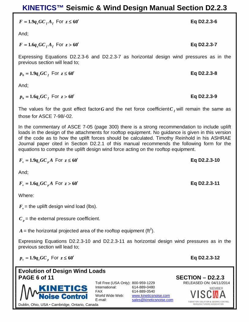
KINETICS™ Seismic & Wind Design Manual Section D2.2.3
Evolution of Design Wind LoadsPAGE 6 of 11 SECTION – D2.2.3
Toll Free (USA Only): 800-959-1229 RELEASED ON: 04/11/2014International: 614-889-0480FAX 614-889-0540World Wide Web: www.kineticsnoise.comE-mail: [email protected]
Dublin, Ohio, USA Cambridge, Ontario, Canada
ffz AGCq.F 91 For 06z Eq D2.2.3-6
And;
ffz AGCq.F 61 For 06z Eq D2.2.3-7
Expressing Equations D2.2.3-6 and D2.2.3-7 as horizontal design wind pressures as in theprevious section will lead to;
fzh GCq.p 91 For 06z Eq D2.2.3-8
And;
fzh GCq.p 61 For 06z Eq D2.2.3-9
The values for the gust effect factorG and the net force coefficient fC will remain the same asthose for ASCE 7-98/-02.
In the commentary of ASCE 7-05 (page 300) there is a strong recommendation to include upliftloads in the design of the attachments for rooftop equipment. No guidance is given in this versionof the code as to how the uplift forces should be calculated. Timothy Reinhold in his ASHRAEJournal paper cited in Section D2.2.1 of this manual recommends the following form for theequations to compute the uplift design wind force acting on the rooftop equipment.
AGCq.F pzv 91 For 06z Eq D2.2.3-10
And;
AGCq.F pzv 61 For 06z Eq D2.2.3-11
Where:
vF = the uplift design wind load (lbs).
pC = the external pressure coefficient.
A = the horizontal projected area of the rooftop equipment (ft2).
Expressing Equations D2.2.3-10 and D2.2.3-11 as horizontal design wind pressures as in theprevious section will lead to;
pzv GCq.p 91 For 06z Eq D2.2.3-12
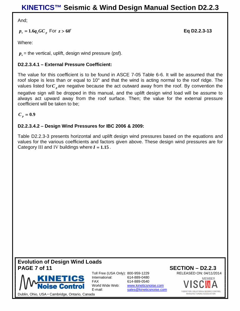
KINETICS™ Seismic & Wind Design Manual Section D2.2.3
Evolution of Design Wind LoadsPAGE 7 of 11 SECTION – D2.2.3
Toll Free (USA Only): 800-959-1229 RELEASED ON: 04/11/2014International: 614-889-0480FAX 614-889-0540World Wide Web: www.kineticsnoise.comE-mail: [email protected]
Dublin, Ohio, USA Cambridge, Ontario, Canada
And;
pzv GCq.p 61 For 06z Eq D2.2.3-13
Where:
vp = the vertical, uplift, design wind pressure (psf).
D2.2.3.4.1 – External Pressure Coefficient:
The value for this coefficient is to be found in ASCE 7-05 Table 6-6. It will be assumed that theroof slope is less than or equal to 10° and that the wind is acting normal to the roof ridge. Thevalues listed for pC are negative because the act outward away from the roof. By convention thenegative sign will be dropped in this manual, and the uplift design wind load will be assume toalways act upward away from the roof surface. Then; the value for the external pressurecoefficient will be taken to be;
90.C p
D2.2.3.4.2 – Design Wind Pressures for IBC 2006 & 2009:
Table D2.2.3-3 presents horizontal and uplift design wind pressures based on the equations andvalues for the various coefficients and factors given above. These design wind pressures are forCategory III and IV buildings where 151.I .
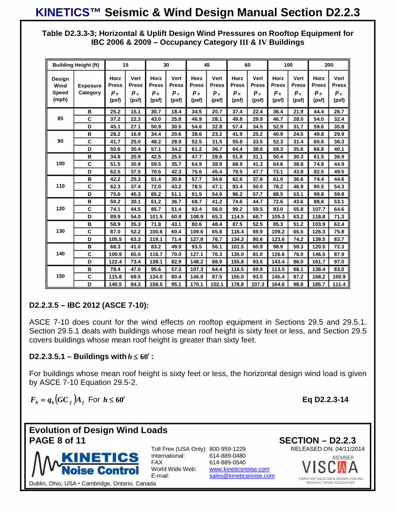
KINETICS™ Seismic & Wind Design Manual Section D2.2.3
Evolution of Design Wind LoadsPAGE 8 of 11 SECTION – D2.2.3
Toll Free (USA Only): 800-959-1229 RELEASED ON: 04/11/2014International: 614-889-0480FAX 614-889-0540World Wide Web: www.kineticsnoise.comE-mail: [email protected]
Dublin, Ohio, USA Cambridge, Ontario, Canada
Table D2.3.3-3; Horizontal & Uplift Design Wind Pressures on Rooftop Equipment forIBC 2006 & 2009 – Occupancy Category III & IV Buildings
DesignWindSpeed(mph)
ExposureCategory
HorzPressp h
(psf)
VertPressp v
(psf)
HorzPressp h
(psf)
VertPressp v
(psf)
HorzPressp h
(psf)
VertPress
p v(psf)
HorzPressp h
(psf)
VertPressp v
(psf)
HorzPressp h
(psf)
VertPress
p v(psf)
HorzPressp h
(psf)
VertPress
p v(psf)
B 25.2 15.1 30.7 18.4 34.5 20.7 37.4 22.4 36.4 21.9 44.4 26.7C 37.2 22.3 43.0 25.8 46.9 28.1 49.8 29.9 46.7 28.0 54.0 32.4D 45.1 27.1 50.9 30.5 54.6 32.8 57.4 34.5 52.9 31.7 59.6 35.8B 28.2 16.9 34.4 20.6 38.6 23.2 41.9 25.2 40.9 24.5 49.8 29.9C 41.7 25.0 48.2 28.9 52.5 31.5 55.8 33.5 52.3 31.4 60.6 36.3D 50.6 30.4 57.1 34.2 61.2 36.7 64.4 38.6 59.3 35.6 66.8 40.1B 34.8 20.9 42.5 25.5 47.7 28.6 51.8 31.1 50.4 30.3 61.5 36.9C 51.5 30.9 59.5 35.7 64.9 38.9 68.9 41.3 64.6 38.8 74.8 44.9D 62.5 37.5 70.5 42.3 75.6 45.4 79.5 47.7 73.1 43.9 82.5 49.5B 42.2 25.3 51.4 30.8 57.7 34.6 62.6 37.6 61.0 36.6 74.4 44.6C 62.3 37.4 72.0 43.2 78.5 47.1 83.4 50.0 78.2 46.9 90.5 54.3D 75.6 45.3 85.2 51.1 91.5 54.9 96.2 57.7 88.5 53.1 99.8 59.9B 50.2 30.1 61.2 36.7 68.7 41.2 74.6 44.7 72.6 43.6 88.6 53.1C 74.1 44.5 85.7 51.4 93.4 56.0 99.2 59.5 93.0 55.8 107.7 64.6D 89.9 54.0 101.5 60.9 108.9 65.3 114.5 68.7 105.3 63.2 118.8 71.3B 58.9 35.3 71.8 43.1 80.6 48.4 87.5 52.5 85.3 51.2 103.9 62.4C 87.0 52.2 100.6 60.4 109.6 65.8 116.4 69.9 109.2 65.5 126.3 75.8D 105.5 63.3 119.1 71.4 127.8 76.7 134.3 80.6 123.6 74.2 139.5 83.7B 68.3 41.0 83.2 49.9 93.5 56.1 101.5 60.9 98.9 59.3 120.5 72.3C 100.9 60.5 116.7 70.0 127.1 76.3 135.0 81.0 126.6 76.0 146.5 87.9D 122.4 73.4 138.1 82.9 148.2 88.9 155.8 93.5 143.4 86.0 161.7 97.0B 78.4 47.0 95.6 57.3 107.3 64.4 116.5 69.9 113.5 68.1 138.4 83.0C 115.8 69.5 134.0 80.4 145.9 87.5 155.0 93.0 145.4 87.2 168.2 100.9D 140.5 84.3 158.5 95.1 170.1 102.1 178.8 107.3 164.6 98.8 185.7 111.4
100 20015 30 45 60Building Height (ft)
85
90
100
150
110
120
130
140
D2.2.3.5 – IBC 2012 (ASCE 7-10):
ASCE 7-10 does count for the wind effects on rooftop equipment in Sections 29.5 and 29.5.1.Section 29.5.1 deals with buildings whose mean roof height is sixty feet or less, and Section 29.5covers buildings whose mean roof height is greater than sixty feet.
D2.2.3.5.1 – Buildings with 06h :
For buildings whose mean roof height is sixty feet or less, the horizontal design wind load is givenby ASCE 7-10 Equation 29.5-2.
ffhh AGCqF For 06h Eq D2.2.3-14
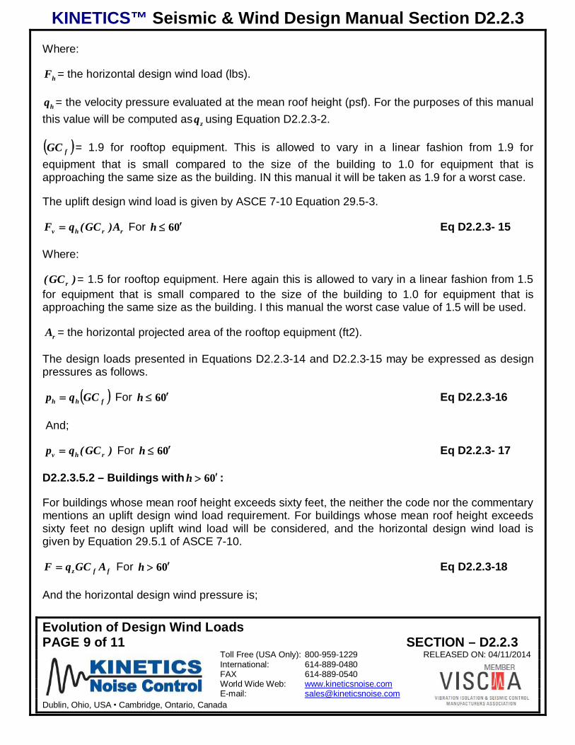
KINETICS™ Seismic & Wind Design Manual Section D2.2.3
Evolution of Design Wind LoadsPAGE 9 of 11 SECTION – D2.2.3
Toll Free (USA Only): 800-959-1229 RELEASED ON: 04/11/2014International: 614-889-0480FAX 614-889-0540World Wide Web: www.kineticsnoise.comE-mail: [email protected]
Dublin, Ohio, USA Cambridge, Ontario, Canada
Where:
hF = the horizontal design wind load (lbs).
hq = the velocity pressure evaluated at the mean roof height (psf). For the purposes of this manualthis value will be computed as zq using Equation D2.2.3-2.
fGC = 1.9 for rooftop equipment. This is allowed to vary in a linear fashion from 1.9 forequipment that is small compared to the size of the building to 1.0 for equipment that isapproaching the same size as the building. IN this manual it will be taken as 1.9 for a worst case.
The uplift design wind load is given by ASCE 7-10 Equation 29.5-3.
rrhv A)GC(qF For 06h Eq D2.2.3- 15
Where:
)GC( r = 1.5 for rooftop equipment. Here again this is allowed to vary in a linear fashion from 1.5for equipment that is small compared to the size of the building to 1.0 for equipment that isapproaching the same size as the building. I this manual the worst case value of 1.5 will be used.
rA = the horizontal projected area of the rooftop equipment (ft2).
The design loads presented in Equations D2.2.3-14 and D2.2.3-15 may be expressed as designpressures as follows.
fhh GCqp For 06h Eq D2.2.3-16
And;
)GC(qp rhv For 06h Eq D2.2.3- 17
D2.2.3.5.2 – Buildings with 06h :
For buildings whose mean roof height exceeds sixty feet, the neither the code nor the commentarymentions an uplift design wind load requirement. For buildings whose mean roof height exceedssixty feet no design uplift wind load will be considered, and the horizontal design wind load isgiven by Equation 29.5.1 of ASCE 7-10.
ffz AGCqF For 06h Eq D2.2.3-18
And the horizontal design wind pressure is;

KINETICS™ Seismic & Wind Design Manual Section D2.2.3
Evolution of Design Wind LoadsPAGE 10 of 11 SECTION – D2.2.3
Toll Free (USA Only): 800-959-1229 RELEASED ON: 04/11/2014International: 614-889-0480FAX 614-889-0540World Wide Web: www.kineticsnoise.comE-mail: [email protected]
Dublin, Ohio, USA Cambridge, Ontario, Canada
fzh GCqp For 06h Eq D2.2.3-19
For this manual, the value ofq will be evaluated using Equation D2.2.3-1 at the mean roof heightof the building. The values ofG and fC will be as before for ASCE 7-98/02/05.
D2.2.3.5.3 – Design Wind Pressures for IBC 2012 (ASCE 7-10):
The design wind pressures for IBC 2012 (ASCE 7-10) are presented below in Table D2.2.3-4.Note that there are no vertical uplift pressures listed for mean roof heights exceeding sixty feet.This table reflects the 30 mph increase across the board in design wind loads.
Table D2.2.3-4; Design Wind Pressures on Rooftop Equipment for IBC 2012 (ASCE 7-10)Risk Category III & IV Buildings
DesignWindSpeed(mph)
ExposureCategory
HorzPress
p h(psf)
VertPressp v
(psf)
HorzPressp h
(psf)
VertPressp v
(psf)
HorzPressp h
(psf)
VertPress
p v(psf)
HorzPressp h
(psf)
VertPress
p v(psf)
HorzPressp h
(psf)
VertPressp v
a
(psf)
HorzPressp h
(psf)
VertPressp v
a
(psf)
B 31.4 24.8 38.3 30.2 43.0 34.0 46.7 36.9 36.3 0.0 44.2 0.0C 46.4 36.6 53.7 42.4 58.5 46.2 62.1 49.1 46.4 0.0 53.7 0.0D 56.3 44.5 63.5 50.2 68.2 53.8 71.7 56.6 52.6 0.0 59.3 0.0B 34.2 27.0 41.7 32.9 46.8 37.0 50.8 40.1 39.5 0.0 48.1 0.0C 50.5 39.9 58.5 46.2 63.7 50.3 67.7 53.4 50.6 0.0 58.5 0.0D 61.3 48.4 69.2 54.6 74.2 58.6 78.1 61.6 57.2 0.0 64.6 0.0B 40.2 31.7 49.0 38.6 55.0 43.4 59.7 47.1 46.3 0.0 56.5 0.0C 59.3 46.8 68.6 54.2 74.7 59.0 79.4 62.7 59.3 0.0 68.7 0.0D 72.0 56.8 81.2 64.1 87.1 68.8 91.6 72.3 67.2 0.0 75.8 0.0B 46.6 36.8 56.8 44.8 63.7 50.3 69.2 54.6 53.7 0.0 65.5 0.0C 68.8 54.3 79.6 62.8 86.7 68.4 92.1 72.7 68.8 0.0 79.6 0.0D 83.5 65.9 94.2 74.4 101.1 79.8 106.2 83.9 77.9 0.0 87.9 0.0B 53.5 42.2 65.2 51.5 73.2 57.8 79.4 62.7 61.7 0.0 75.2 0.0C 79.0 62.3 91.4 72.1 99.5 78.6 105.7 83.5 79.0 0.0 91.4 0.0D 95.8 75.7 108.1 85.4 116.0 91.6 122.0 96.3 89.4 0.0 100.9 0.0B 60.8 48.0 74.2 58.5 83.3 65.7 90.4 71.4 70.2 0.0 85.6 0.0C 89.8 70.9 104.0 82.1 113.2 89.4 120.3 95.0 89.9 0.0 104.0 0.0D 109.0 86.1 123.0 97.1 132.0 104.2 138.8 109.6 101.8 0.0 114.8 0.0B 68.7 54.2 83.7 66.1 94.0 74.2 102.0 80.6 79.2 0.0 96.6 0.0C 101.4 80.1 117.4 92.7 127.8 100.9 135.8 107.2 101.5 0.0 117.4 0.0D 123.1 97.2 138.9 109.6 149.0 117.6 156.7 123.7 114.9 0.0 129.6 0.0B 77.0 60.8 93.8 74.1 105.4 83.2 114.4 90.3 88.8 0.0 108.3 0.0C 113.7 89.8 131.6 103.9 143.3 113.1 152.2 120.2 113.8 0.0 131.6 0.0D 138.0 109.0 155.7 122.9 167.1 131.9 175.6 138.7 128.8 0.0 145.3 0.0B 85.8 67.7 104.6 82.6 117.4 92.7 127.5 100.6 99.0 0.0 120.7 0.0C 126.7 100.0 146.6 115.7 159.7 126.1 169.6 133.9 126.8 0.0 146.7 0.0D 153.8 121.4 173.5 136.9 186.1 146.9 195.7 154.5 143.5 0.0 161.9 0.0B 95.0 75.0 115.9 91.5 130.1 102.7 141.2 111.5 109.7 0.0 133.7 0.0C 140.4 110.8 162.4 128.2 176.9 139.7 188.0 148.4 140.5 0.0 162.5 0.0D 170.4 134.5 192.2 151.7 206.2 162.8 216.8 171.2 159.0 0.0 179.4 0.0
a. ASCE 7-10 does not require uplift for rooftop euipment on buildings over 60' in height.
200
140
150
160
170
180
190
Building Height (ft)
115
120
130
100 20015 30 45 60
KINETICS™ Seismic & Wind Design Manual Section D2.2.3
Evolution of Design Wind LoadsPAGE 11 of 11 SECTION – D2.2.3
Toll Free (USA Only): 800-959-1229 RELEASED ON: 04/11/2014International: 614-889-0480FAX 614-889-0540World Wide Web: www.kineticsnoise.comE-mail: [email protected]
Dublin, Ohio, USA Cambridge, Ontario, Canada
D2.3.3.6 – Summary:
1. The design wind loads increased greatly across the board between IBC 2000/2003 and IBC2006/2009. The design wind loads also increased between IBC 2006/2009 and IBC 2012.However, the increase was smaller for the lower brackets of the Design Wind Speed, and theincrease was much greater at the higher brackets of the Design Wind Speed.
2. IBC 2006/2009 saw the addition of a design uplift load requirement in the commentary ofASCE 7-05. For IBC 2012 this design uplift load requirement is specified in the body of thecode in ASCE 7-10 in Chapter 29. For IBC 2006/2009 the uplift load requirement was notlimited to a mean roof height of sixty feet or less. For IBC 2012, the design uplift loadrequirement applies only to buildings whose mean roof height is sixty feet or less.
3. The design wind pressures given in Tables D2.2.3-2, D2.2.3-3, and D2.2.3-4 may be used toestimate the wind loadings on rooftop equipment in order to make preliminary selections ofwind restraint devices. The actual selection of the restraint devices must be reviewed andapproved by Kinetics Noise Control and the Structural Engineer of Record.
KINETICS™ Seismic & Wind Design Manual Section D2.3
INTRODUCTIONPAGE 1 of 1 SECTION – D2.3.1
Toll Free (USA Only): 800-959-1229 RELEASED ON: 04/11/2014International: 614-889-0480FAX 614-889-0540World Wide Web: www.kineticsnoise.comE-mail: [email protected]
Dublin, Ohio, USA Cambridge, Ontario, Canada
NBCC-OBC SEISMICD2.3.1 – Introduction:The purpose of this guide is to provide design professionals, contractors, and building officialsresponsible for the MEP, Mechanical, Electrical, and Plumbing, with the information and guidancerequired to ensure that the seismic restraints required for a specific project are selected and/ordesigned, and installed in accordance with the code provisions. This guide will be written inseveral easily referenced sections that deal with specific portions of the code.
This guide is based on the National Building Code of Canada 2005 (NBCC 2005). The NBCC2005 appears to be very different in the formulation of the design forces than the previous NBCC1995 version. This document will be based entirely on the newer NBCC 2005 version.
1. National Building Code of Canada 2005; Canadian Commission on Building and Fire Codesand National Research Council of Canada, 1200 Montreal RD, Ottawa, ON K1A 9Z9 ChapterDivision B – Part 4 Structural Design.
The selection and installation of the proper seismic restraints for MEP systems requires goodcoordination with the design professionals and contractors involved with the building project. Agood spirit of cooperation and coordination is especially required for projects that have beendesignated as post-disaster buildings, such as hospitals, emergency response centers, police andfire stations. Coordination between the various design professionals and contractors will be aconstant theme throughout this guide. This coordination is vital for the following reasons.
1. The seismic restraints that are installed for a system can and will interfere with those ofanother unless restraint locations are well coordinated.
2. The space required for the installed restraints can cause problems if non-structural wallsneed to be penetrated, or other MEP components are in the designed load path for therestraints.
3. The building end of the seismic restraints must always be attached to structure that isadequate to carry the code mandated design seismic loads. It is the responsibility of thestructural engineer of record to verify this.
KINETICS™ Seismic & Wind Design Manual Section D2.3.2
REQUIRED BASIC PROJECT INFORMATIONPAGE 1 of 10 SECTION – D2.3.2
Toll Free (USA Only): 800-959-1229 RELEASED ON: 04/11/2014International: 614-889-0480FAX 614-889-0540World Wide Web: www.kineticsnoise.comE-mail: [email protected]
Dublin, Ohio, USA Cambridge, Ontario, Canada
REQUIRED BASIC PROJECT INFORMATION
D2.3.2.1 – Introduction:
As with any design job, there is certain basic information that is required before seismic restraintscan be selected and placed. The building owner, architect, and structural engineer make thedecisions that form the basis for the information required to select the seismic restraints for thepipe and duct systems in the building. This is information that should be included in thespecification and bid package for the project. It also should appear on the first sheet of thestructural drawings. For consistency, it is good practice to echo this information in the specificationfor each building system, and on the first sheet of the drawings for each system. In this fashion,this information is available to all of the contractors and suppliers that will have a need to know.
D2.3.2.2 – Building Use-Nature of Occupancy [Sentence 4.1.2.1]1:
How a building is to be used greatly affects the level of seismic restraint that is required for theMEP (Mechanical, Electrical, and Plumbing) components. In the NBCC 2005 the building use isdefined through the Importance Category, which ranges in four stages from Low to Post-Disaster.Table D2.3.2-1 below summarizes the information found in Tables 4.1.2.1 of the NBCC 2005. Thenature of the building use, or its Occupancy Category, is determined by the building owner and thearchitect of record.
D2.3.2.3 – Site Class-Soil Type [Sentences 4.1.8.4.(2) and 4.1.8.1.(3)]:
The Site Class is related to the type of soil and rock strata that directly underlies the building site.
The Site Class ranges from A to F progressing from the stiffest to the softest strata. Table D2.3.2-2 lists the various Site Classes and their corresponding strata.
Generally the structural engineer is responsible for determining the Site Class for a project. If thestructural engineer’s firm does not have a geotechnical engineer on staff, this job will becontracted to a geotechnical firm. The site profile is normally obtained by drilling several cores onthe property. Unlike the U. S. building codes, there is no published default Site Class that may bethat can be substituted for the actual Site Class that is determined from soils testing performed atthe actual project location.
1 References in brackets [Sentence 4.1.2.1 and Table 4.1.2.1] apply to sections, tables, and/or equations in theNational Building Code of Canada 2005.
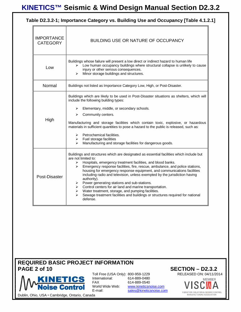
KINETICS™ Seismic & Wind Design Manual Section D2.3.2
REQUIRED BASIC PROJECT INFORMATIONPAGE 2 of 10 SECTION – D2.3.2
Toll Free (USA Only): 800-959-1229 RELEASED ON: 04/11/2014International: 614-889-0480FAX 614-889-0540World Wide Web: www.kineticsnoise.comE-mail: [email protected]
Dublin, Ohio, USA Cambridge, Ontario, Canada
Table D2.3.2-1; Importance Category vs. Building Use and Occupancy [Table 4.1.2.1]
IMPORTANCECATEGORY BUILDING USE OR NATURE OF OCCUPANCY
LowBuildings whose failure will present a low direct or indirect hazard to human life
Low human occupancy buildings where structural collapse is unlikely to causeinjury or other serious consequences.
Minor storage buildings and structures.
Normal Buildings not listed as Importance Category Low, High, or Post-Disaster.
High
Buildings which are likely to be used in Post-Disaster situations as shelters, which willinclude the following building types:
Elementary, middle, or secondary schools.
Community centers.
Manufacturing and storage facilities which contain toxic, explosive, or hazardousmaterials in sufficient quantities to pose a hazard to the public is released, such as:
Petrochemical facilities. Fuel storage facilities Manufacturing and storage facilities for dangerous goods.
Post-Disaster
Buildings and structures which are designated as essential facilities which include butare not limited to:
Hospitals, emergency treatment facilities, and blood banks. Emergency response facilities, fire, rescue, ambulance, and police stations,
housing for emergency response equipment, and communications facilitiesincluding radio and television, unless exempted by the jurisdiction havingauthority).
Power generating stations and sub-stations. Control centers for air land and marine transportation. Water treatment, storage, and pumping facilities. Sewage treatment facilities and buildings or structures required for national
defense.
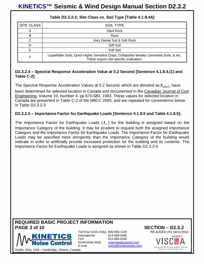
KINETICS™ Seismic & Wind Design Manual Section D2.3.2
REQUIRED BASIC PROJECT INFORMATIONPAGE 3 of 10 SECTION – D2.3.2
Toll Free (USA Only): 800-959-1229 RELEASED ON: 04/11/2014International: 614-889-0480FAX 614-889-0540World Wide Web: www.kineticsnoise.comE-mail: [email protected]
Dublin, Ohio, USA Cambridge, Ontario, Canada
Table D2.3.2-2; Site Class vs. Soil Type [Table 4.1.8.4A]
SITE CLASS SOIL TYPEA Hard RockB RockC Very Dense Soil & Soft RockD Stiff SoilE Soft Soil
F Liquefiable Soils, Quick Highly Sensitive Clays, Collapsible Weakly Cemented Soils, & etc.These require site-specific evaluation.
D2.3.2.4 – Spectral Response Acceleration Value at 0.2 Second [Sentence 4.1.8.4.(1) andTable C-2]
The Spectral Response Acceleration Values at 0.2 Second, which are denoted as 20.aS , havebeen determined for selected location in Canada and documented in the Canadian Journal of CivilEngineering, Volume 10, Number 4, pp 670-680, 1983. These values for selected location inCanada are presented in Table C-2 of the NBCC 2005, and are repeated for convenience belowin Table D2.3.2-3
D2.3.2.5 – Importance Factor for Earthquake Loads [Sentence 4.1.8.5 and Table 4.1.8.5]:
The Importance Factor for Earthquake Loads ( EI ) for the building is assigned based on theImportance Category of the building. It may be prudent to request both the assigned ImportanceCategory and the Importance Factor for Earthquake Loads. The Importance Factor for EarthquakeLoads may be specified more stringently than the Importance Category of the building wouldindicate in order to artificially provide increased protection for the building and its contents. TheImportance Factor for Earthquake Loads is assigned as shown in Table D2.3.2-4
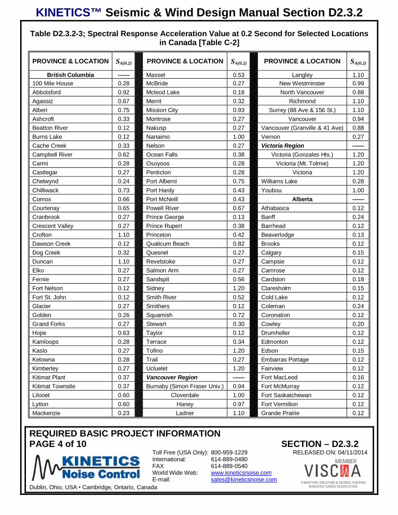
KINETICS™ Seismic & Wind Design Manual Section D2.3.2
REQUIRED BASIC PROJECT INFORMATIONPAGE 4 of 10 SECTION – D2.3.2
Toll Free (USA Only): 800-959-1229 RELEASED ON: 04/11/2014International: 614-889-0480FAX 614-889-0540World Wide Web: www.kineticsnoise.comE-mail: [email protected]
Dublin, Ohio, USA Cambridge, Ontario, Canada
Table D2.3.2-3; Spectral Response Acceleration Value at 0.2 Second for Selected Locationsin Canada [Table C-2]
PROVINCE & LOCATION SA(0.2) PROVINCE & LOCATION SA(0.2) PROVINCE & LOCATION SA(0.2)
British Columbia ------ Masset 0.53 Langley 1.10100 Mile House 0.28 McBride 0.27 New Westminster 0.99Abbotsford 0.92 Mcleod Lake 0.18 North Vancouver 0.88Agassiz 0.67 Merrit 0.32 Richmond 1.10Alberi 0.75 Mission City 0.93 Surrey (88 Ave & 156 St.) 1.10Ashcroft 0.33 Montrose 0.27 Vancouver 0.94Beatton River 0.12 Nakusp 0.27 Vancouver (Granville & 41 Ave) 0.88Burns Lake 0.12 Nanaimo 1.00 Vernon 0.27Cache Creek 0.33 Nelson 0.27 Victoria Region ------Campbell River 0.62 Ocean Falls 0.38 Victoria (Gonzales Hts.) 1.20Carmi 0.28 Osoyoos 0.28 Victoria (Mt. Tolmie) 1.20Castlegar 0.27 Penticton 0.28 Victoria 1.20Chetwynd 0.24 Port Alberni 0.75 Williams Lake 0.28Chilliwack 0.73 Port Hardy 0.43 Youbou 1.00Comox 0.66 Port McNeill 0.43 Alberta ------Courtenay 0.65 Powell River 0.67 Athabasca 0.12Cranbrook 0.27 Prince George 0.13 Banff 0.24Crescent Valley 0.27 Prince Rupert 0.38 Barrhead 0.12Crofton 1.10 Princeton 0.42 Beaverlodge 0.13Dawson Creek 0.12 Qualicum Beach 0.82 Brooks 0.12Dog Creek 0.32 Quesnel 0.27 Calgary 0.15Duncan 1.10 Revelstoke 0.27 Campsie 0.12Elko 0.27 Salmon Arm 0.27 Camrose 0.12Fernie 0.27 Sandspit 0.56 Cardston 0.18Fort Nelson 0.12 Sidney 1.20 Claresholm 0.15Fort St. John 0.12 Smith River 0.52 Cold Lake 0.12Glacier 0.27 Smithers 0.12 Coleman 0.24Golden 0.26 Squamish 0.72 Coronation 0.12Grand Forks 0.27 Stewart 0.30 Cowley 0.20Hope 0.63 Taylor 0.12 Drumheller 0.12Kamloops 0.28 Terrace 0.34 Edmonton 0.12Kaslo 0.27 Tofino 1.20 Edson 0.15Kelowna 0.28 Trail 0.27 Embarras Portage 0.12Kimberley 0.27 Ucluelet 1.20 Fairview 0.12Kitimat Plant 0.37 Vancouver Region ------ Fort MacLeod 0.16Kitimat Townsite 0.37 Burnaby (Simon Fraser Univ.) 0.94 Fort McMurray 0.12Lilooet 0.60 Cloverdale 1.00 Fort Saskatchewan 0.12Lytton 0.60 Haney 0.97 Fort Vermilion 0.12Mackenzie 0.23 Ladner 1.10 Grande Prairie 0.12
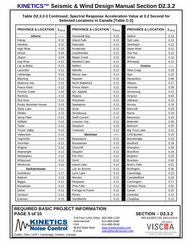
KINETICS™ Seismic & Wind Design Manual Section D2.3.2
REQUIRED BASIC PROJECT INFORMATIONPAGE 5 of 10 SECTION – D2.3.2
Toll Free (USA Only): 800-959-1229 RELEASED ON: 04/11/2014International: 614-889-0480FAX 614-889-0540World Wide Web: www.kineticsnoise.comE-mail: [email protected]
Dublin, Ohio, USA Cambridge, Ontario, Canada
Table D2.3.2-3 Continued; Spectral Response Acceleration Value at 0.2 Second forSelected Locations in Canada [Table C-2]
PROVINCE & LOCATION SA(0.2) PROVINCE & LOCATION SA(0.2) PROVINCE & LOCATION SA(0.2)
Alberta ------ Humboldt Bay 0.12 Selkirk 0.12Habay 0.12 Island Falls 0.12 Spit Lake 0.12Hardisty 0.12 Kamsack 0.12 Steinbach 0.12High River 0.15 Kindersley 0.12 Swan River 0.12Hinton 0.24 Lloydminster 0.12 The Pas 0.12Jasper 0.24 Maple Creek 0.12 Virden 0.12Keg River 0.12 Meadow Lake 0.12 Winnipeg 0.12Lac la Bishe 0.12 Melfort 0.12 Ontario ------Lacombe 0.12 Melville 0.12 Ailsa Craig 0.16Lethbridge 0.15 Moose Jaw 0.12 Ajax 0.22Manning 0.12 Nipawin 0.12 Alexandria 0.68Medicine Hat 0.12 North Battleford 0.12 Alliston 0.17Peace River 0.12 Prince Albert 0.12 Almonte 0.58Pincher Creek 0.19 Qu’ Appelle 0.12 Armstrong 0.12Ranfurly 0.12 Regina 0.12 Arnprior 0.64Red Deer 0.12 Rosetown 0.12 Atikokan 0.12Rocky Mountain House 0.15 Saskatoon 0.12 Aurora 0.19Slave Lake 0.12 Scott 0.12 Bancroft 0.26Stettler 0.12 Strasbourg 0.12 Barrie 0.16Stony Plain 0.12 Swift Current 0.12 Beaverton 0.16Suffield 0.12 Uranium City 0.12 Belleville 0.26Taber 0.12 Weyburn 0.23 Belmont 0.20Turner Valley 0.15 Yorktown 0.12 Big Trout Lake 0.12Valleyview 0.12 Manitoba ------ CFB Borden 0.16Vegreville 0.12 Beausejour 0.12 Bracebridge 0.18Vermilion 0.12 Boussevain 0.12 Bradford 0.18Wagner 0.12 Churchill 0.12 Brampton 0.26Wainwright 0.12 Dauphin 0.12 Brantford 0.24Wetaskiwin 0.12 Flin Flon 0.12 Brighton 0.25Whitecourt 0.12 Gimli 0.12 Brockton 0.40Wimborne 0.12 Island Lake 0.12 Burk’s Falls 0.21
Saskatchewan ------ Lac du Bonnet 0.12 Burlington 0.36Assiniboia 0.17 Lynn Lake 0.12 Cambridge 0.22Battrum 0.12 Morden 0.12 Campbellford 0.23Biggar 0.12 Neepawa 0.12 Cannington 0.17Broadview 0.12 Pine Falls 0.12 Carleton Place 0.52Dafoe 0.12 Portage la Prairie 0.12 Cavan 0.20Dundurn 0.12 Rivers 0.12 Centralia 0.14Estevan 0.15 Sandilands 0.12 Chapleau 0.12
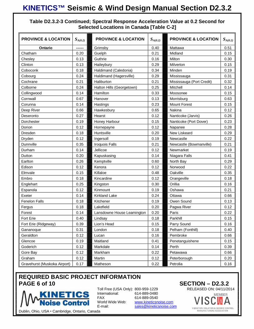
KINETICS™ Seismic & Wind Design Manual Section D2.3.2
REQUIRED BASIC PROJECT INFORMATIONPAGE 6 of 10 SECTION – D2.3.2
Toll Free (USA Only): 800-959-1229 RELEASED ON: 04/11/2014International: 614-889-0480FAX 614-889-0540World Wide Web: www.kineticsnoise.comE-mail: [email protected]
Dublin, Ohio, USA Cambridge, Ontario, Canada
Table D2.3.2-3 Continued; Spectral Response Acceleration Value at 0.2 Second forSelected Locations in Canada [Table C-2]
PROVINCE & LOCATION SA(0.2) PROVINCE & LOCATION SA(0.2) PROVINCE & LOCATION SA(0.2)
Ontario ------ Grimsby 0.40 Mattawa 0.51Chatham 0.20 Guelph 0.21 Midland 0.15Chesley 0.13 Guthrie 0.16 Milton 0.30Clinton 0.13 Haileybury 0.29 Milverton 0.15Coboconk 0.18 Haldimand (Caledonia) 0.34 Minden 0.19Cobourg 0.24 Haldimand (Hagersville) 0.29 Mississauga 0.31Cochrane 0.21 Haliburton 0.21 Mississauga (Port Credit) 0.32Colborne 0.24 Halton Hills (Georgetown) 0.25 Mitchell 0.14Collingwood 0.14 Hamilton 0.33 Moosonee 0.15Cornwall 0.67 Hanover 0.13 Morrisburg 0.63Corunna 0.14 Hastings 0.23 Mount Forest 0.15Deep River 0.66 Hawkesbury 0.65 Nakina 0.12Deseronto 0.27 Hearst 0.12 Nanticoke (Jarvis) 0.26Dorchester 0.19 Honey Harbour 0.15 Nanticoke (Port Dover) 0.23Dorion 0.12 Hornepayne 0.12 Napanee 0.28Dresden 0.18 Huntsville 0.20 New Liskeard 0.29Dryden 0.12 Ingersoll 0.19 Newcastle 0.22Dunnville 0.35 Iroquois Falls 0.21 Newcastle (Bowmanville) 0.21Durham 0.14 Jellicoe 0.12 Newmarket 0.19Dutton 0.20 Kapuskasing 0.14 Niagara Falls 0.41Earlton 0.26 Kemptville 0.60 North Bay 0.29Edison 0.12 Kenora 0.12 Norwood 0.22Elmvale 0.15 Killaloe 0.48 Oakville 0.35Embro 0.18 Kincardine 0.12 Orangeville 0.18Englehart 0.25 Kingston 0.30 Orillia 0.16Espanola 0.12 Kinmount 0.19 Oshawa 0.21Exeter 0.14 Kirkland Lake 0.24 Ottawa 0.66Fenelon Falls 0.18 Kitchener 0.19 Owen Sound 0.13Fergus 0.18 Lakefield 0.20 Pagwa River 0.12Forest 0.14 Lansdowne House Leamington 0.20 Paris 0.22Fort Erie 0.40 Lindsay 0.18 Parkhill 0.15Fort Erie (Ridgeway) 0.39 Lion’s Head 0.15 Parry Sound 0.16Gananoque 0.31 London 0.18 Pelham (Fonthill) 0.40Geraldton 0.12 Lucan 0.16 Pembroke 0.66Glencoe 0.19 Maitland 0.41 Penetanguishene 0.15Goderich 0.12 Markdale 0.14 Perth 0.39Gore Bay 0.12 Markham 0.22 Petawawa 0.66Graham 0.12 Martin 0.12 Peterborough 0.20Gravehurst (Muskoka Airport) 0.17 Matheson 0.22 Petrolia 0.16
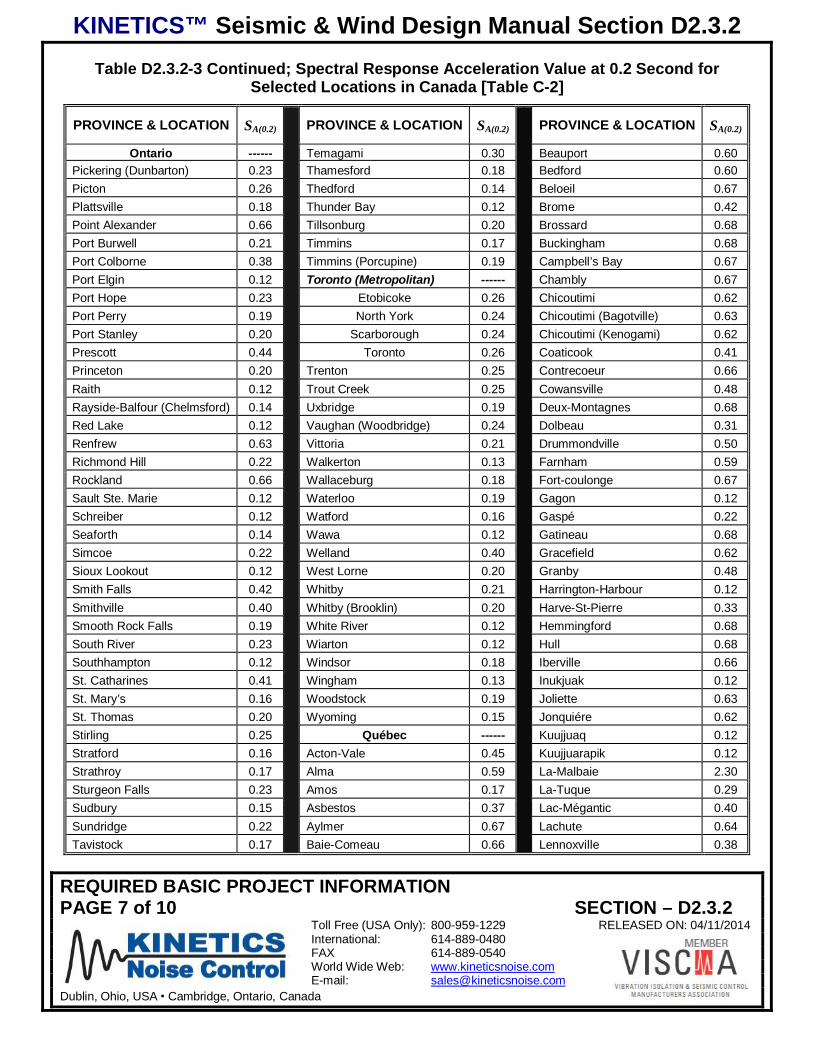
KINETICS™ Seismic & Wind Design Manual Section D2.3.2
REQUIRED BASIC PROJECT INFORMATIONPAGE 7 of 10 SECTION – D2.3.2
Toll Free (USA Only): 800-959-1229 RELEASED ON: 04/11/2014International: 614-889-0480FAX 614-889-0540World Wide Web: www.kineticsnoise.comE-mail: [email protected]
Dublin, Ohio, USA Cambridge, Ontario, Canada
Table D2.3.2-3 Continued; Spectral Response Acceleration Value at 0.2 Second forSelected Locations in Canada [Table C-2]
PROVINCE & LOCATION SA(0.2) PROVINCE & LOCATION SA(0.2) PROVINCE & LOCATION SA(0.2)
Ontario ------ Temagami 0.30 Beauport 0.60Pickering (Dunbarton) 0.23 Thamesford 0.18 Bedford 0.60Picton 0.26 Thedford 0.14 Beloeil 0.67Plattsville 0.18 Thunder Bay 0.12 Brome 0.42Point Alexander 0.66 Tillsonburg 0.20 Brossard 0.68Port Burwell 0.21 Timmins 0.17 Buckingham 0.68Port Colborne 0.38 Timmins (Porcupine) 0.19 Campbell’s Bay 0.67Port Elgin 0.12 Toronto (Metropolitan) ------ Chambly 0.67Port Hope 0.23 Etobicoke 0.26 Chicoutimi 0.62Port Perry 0.19 North York 0.24 Chicoutimi (Bagotville) 0.63Port Stanley 0.20 Scarborough 0.24 Chicoutimi (Kenogami) 0.62Prescott 0.44 Toronto 0.26 Coaticook 0.41Princeton 0.20 Trenton 0.25 Contrecoeur 0.66Raith 0.12 Trout Creek 0.25 Cowansville 0.48Rayside-Balfour (Chelmsford) 0.14 Uxbridge 0.19 Deux-Montagnes 0.68Red Lake 0.12 Vaughan (Woodbridge) 0.24 Dolbeau 0.31Renfrew 0.63 Vittoria 0.21 Drummondville 0.50Richmond Hill 0.22 Walkerton 0.13 Farnham 0.59Rockland 0.66 Wallaceburg 0.18 Fort-coulonge 0.67Sault Ste. Marie 0.12 Waterloo 0.19 Gagon 0.12Schreiber 0.12 Watford 0.16 Gaspé 0.22Seaforth 0.14 Wawa 0.12 Gatineau 0.68Simcoe 0.22 Welland 0.40 Gracefield 0.62Sioux Lookout 0.12 West Lorne 0.20 Granby 0.48Smith Falls 0.42 Whitby 0.21 Harrington-Harbour 0.12Smithville 0.40 Whitby (Brooklin) 0.20 Harve-St-Pierre 0.33Smooth Rock Falls 0.19 White River 0.12 Hemmingford 0.68South River 0.23 Wiarton 0.12 Hull 0.68Southhampton 0.12 Windsor 0.18 Iberville 0.66St. Catharines 0.41 Wingham 0.13 Inukjuak 0.12St. Mary’s 0.16 Woodstock 0.19 Joliette 0.63St. Thomas 0.20 Wyoming 0.15 Jonquiére 0.62Stirling 0.25 Québec ------ Kuujjuaq 0.12Stratford 0.16 Acton-Vale 0.45 Kuujjuarapik 0.12Strathroy 0.17 Alma 0.59 La-Malbaie 2.30Sturgeon Falls 0.23 Amos 0.17 La-Tuque 0.29Sudbury 0.15 Asbestos 0.37 Lac-Mégantic 0.40Sundridge 0.22 Aylmer 0.67 Lachute 0.64Tavistock 0.17 Baie-Comeau 0.66 Lennoxville 0.38
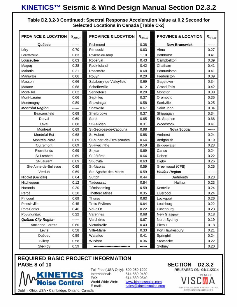
KINETICS™ Seismic & Wind Design Manual Section D2.3.2
REQUIRED BASIC PROJECT INFORMATIONPAGE 8 of 10 SECTION – D2.3.2
Toll Free (USA Only): 800-959-1229 RELEASED ON: 04/11/2014International: 614-889-0480FAX 614-889-0540World Wide Web: www.kineticsnoise.comE-mail: [email protected]
Dublin, Ohio, USA Cambridge, Ontario, Canada
Table D2.3.2-3 Continued; Spectral Response Acceleration Value at 0.2 Second forSelected Locations in Canada [Table C-2]
PROVINCE & LOCATION SA(0.2) PROVINCE & LOCATION SA(0.2) PROVINCE & LOCATION SA(0.2)
Québec ------ Richmond 0.38 New Brunswick ------Léry 0.70 Rimouski 0.63 Alma 0.27Loretteville 0.63 Rivière-du-loup 1.10 Bathhurst 0.41Louisevilee 0.63 Roberval 0.43 Campbellton 0.39Magog 0.38 Rock-Island 0.42 Chatham 0.41Malartic 0.21 Rosemère 0.68 Edmundston 0.41Maniwaki 0.66 Rouyn 0.20 Fredericton 0.39Masson 0.66 Salaberry-de-Valleyfield 0.69 Gagetown 0.34Matane 0.68 Schefferville 0.12 Grand Falls 0.42Mont-Joli 0.62 Senneterre 0.20 Moncton 0.30Mont-Laurier 0.66 Sept-Îles 0.37 Oromocto 0.36Montmagny 0.89 Shawinigan 0.58 Sackville 0.25Montréal Region ------ Shawville 0.67 Saint John 0.34
Beaconsfield 0.69 Sherbrooke 0.37 Shippagan 0.34Dorval 0.69 Sorel 0.65 St. Stephen 0.66Laval 0.68 St-Félicien 0.31 Woodstock 0.41
Montréal 0.69 St-Georges-de-Cacouna 0.98 Nova Scotia ------Montréal-Est 0.68 St-Hubert 0.68 Amherst 0.24
Montréal-Nord 0.69 St-hubert-de-Temiscouata 0.64 Antigonish 0.19Outremont 0.69 St-Hyacinthe 0.59 Bridgewater 0.23Pierrefonds 0.69 St-jean 0.69 Canso 0.24St-Lambert 0.69 St-Jérôme 0.64 Debert 0.22St-Laurent 0.69 St-Jovite 0.63 Digby 0.26
Ste-Anne-de-Bellevue 0.69 St-Nicolas 0.59 Greenwood (CFB) 0.25Verdun 0.69 Ste-Agathe-des-Monts 0.59 Halifax Region ------
Nicolet (Gentilly) 0.64 Sutton 0.44 Dartmouth 0.23Nitchequon 0.12 Tadoussac 0.84 Halifax 0.23Noranda 0.20 Témiscaming 0.59 Kentville 0.24Percé 0.20 Thetford Mines 0.35 Liverpool 0.24Pincourt 0.69 Thurso 0.63 Lockeport 0.26Plessisville 0.45 Trois-Rivières 0.64 Louisburg 0.22Port-Cartier 0.46 Val-d’Or 0.22 Lunenburg 0.23Povungnituk 0.22 Varennes 0.68 New Glasgow 0.18Québec City Region ------ Verchères 0.67 North Sydney 0.19
Ancienne-Lorette 0.60 Victoriaville 0.43 Pictou 0.18Levis 0.58 Ville-Marie 0.33 Port Hawkesbury 0.21
Québec 0.59 Waterloo 0.41 Springhill 0.24Sillery 0.58 Windsor 0.36 Stewiacke 0.22
Ste-Foy 0.59 ------------------------------- ------ Sydney 0.20
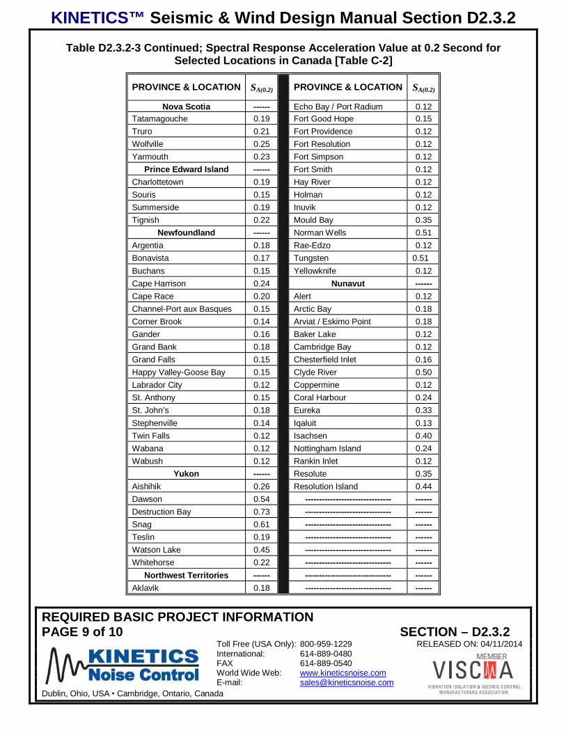
KINETICS™ Seismic & Wind Design Manual Section D2.3.2
REQUIRED BASIC PROJECT INFORMATIONPAGE 9 of 10 SECTION – D2.3.2
Toll Free (USA Only): 800-959-1229 RELEASED ON: 04/11/2014International: 614-889-0480FAX 614-889-0540World Wide Web: www.kineticsnoise.comE-mail: [email protected]
Dublin, Ohio, USA Cambridge, Ontario, Canada
Table D2.3.2-3 Continued; Spectral Response Acceleration Value at 0.2 Second forSelected Locations in Canada [Table C-2]
PROVINCE & LOCATION SA(0.2) PROVINCE & LOCATION SA(0.2)
Nova Scotia ------ Echo Bay / Port Radium 0.12Tatamagouche 0.19 Fort Good Hope 0.15Truro 0.21 Fort Providence 0.12Wolfville 0.25 Fort Resolution 0.12Yarmouth 0.23 Fort Simpson 0.12
Prince Edward Island ------ Fort Smith 0.12Charlottetown 0.19 Hay River 0.12Souris 0.15 Holman 0.12Summerside 0.19 Inuvik 0.12Tignish 0.22 Mould Bay 0.35
Newfoundland ------ Norman Wells 0.51Argentia 0.18 Rae-Edzo 0.12Bonavista 0.17 Tungsten 0.51Buchans 0.15 Yellowknife 0.12Cape Harrison 0.24 Nunavut ------Cape Race 0.20 Alert 0.12Channel-Port aux Basques 0.15 Arctic Bay 0.18Corner Brook 0.14 Arviat / Eskimo Point 0.18Gander 0.16 Baker Lake 0.12Grand Bank 0.18 Cambridge Bay 0.12Grand Falls 0.15 Chesterfield Inlet 0.16Happy Valley-Goose Bay 0.15 Clyde River 0.50Labrador City 0.12 Coppermine 0.12St. Anthony 0.15 Coral Harbour 0.24St. John’s 0.18 Eureka 0.33Stephenville 0.14 Iqaluit 0.13Twin Falls 0.12 Isachsen 0.40Wabana 0.12 Nottingham Island 0.24Wabush 0.12 Rankin Inlet 0.12
Yukon ------ Resolute 0.35Aishihik 0.26 Resolution Island 0.44Dawson 0.54 ------------------------------- ------Destruction Bay 0.73 ------------------------------- ------Snag 0.61 ------------------------------- ------Teslin 0.19 ------------------------------- ------Watson Lake 0.45 ------------------------------- ------Whitehorse 0.22 ------------------------------- ------
Northwest Territories ------ ------------------------------- ------Aklavik 0.18 ------------------------------- ------
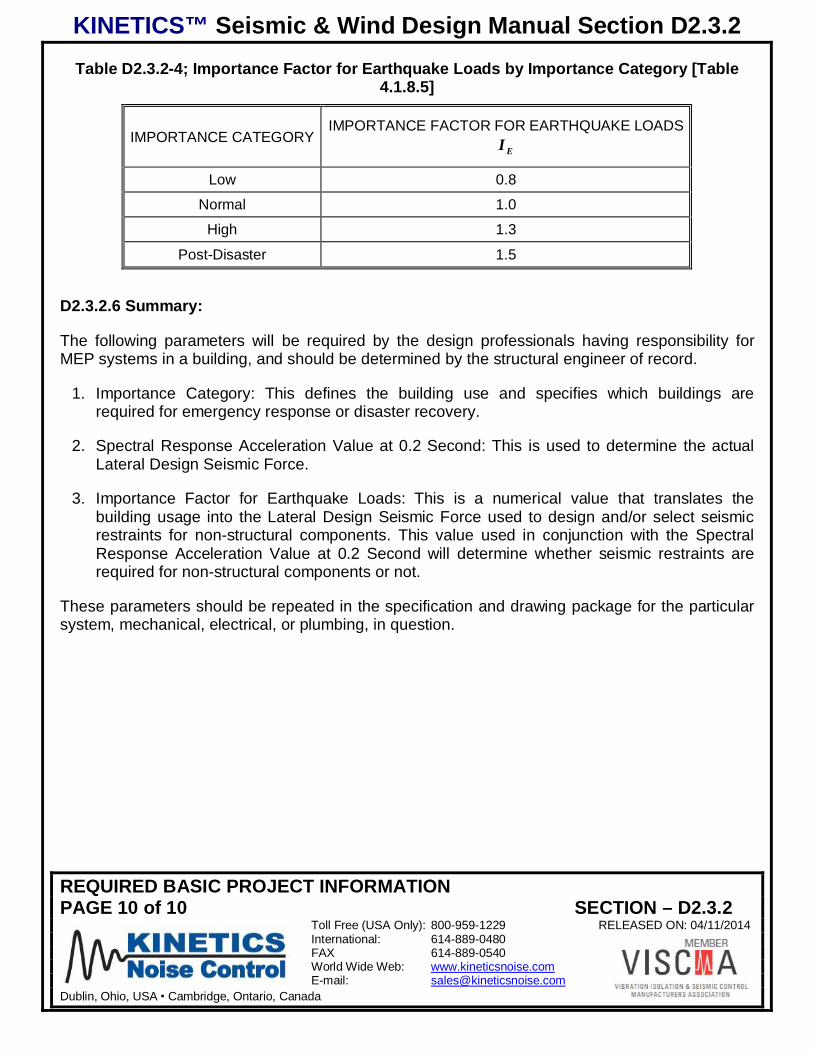
KINETICS™ Seismic & Wind Design Manual Section D2.3.2
REQUIRED BASIC PROJECT INFORMATIONPAGE 10 of 10 SECTION – D2.3.2
Toll Free (USA Only): 800-959-1229 RELEASED ON: 04/11/2014International: 614-889-0480FAX 614-889-0540World Wide Web: www.kineticsnoise.comE-mail: [email protected]
Dublin, Ohio, USA Cambridge, Ontario, Canada
Table D2.3.2-4; Importance Factor for Earthquake Loads by Importance Category [Table4.1.8.5]
IMPORTANCE CATEGORYIMPORTANCE FACTOR FOR EARTHQUAKE LOADS
EI
Low 0.8
Normal 1.0
High 1.3
Post-Disaster 1.5
D2.3.2.6 Summary:
The following parameters will be required by the design professionals having responsibility forMEP systems in a building, and should be determined by the structural engineer of record.
1. Importance Category: This defines the building use and specifies which buildings arerequired for emergency response or disaster recovery.
2. Spectral Response Acceleration Value at 0.2 Second: This is used to determine the actualLateral Design Seismic Force.
3. Importance Factor for Earthquake Loads: This is a numerical value that translates thebuilding usage into the Lateral Design Seismic Force used to design and/or select seismicrestraints for non-structural components. This value used in conjunction with the SpectralResponse Acceleration Value at 0.2 Second will determine whether seismic restraints arerequired for non-structural components or not.
These parameters should be repeated in the specification and drawing package for the particularsystem, mechanical, electrical, or plumbing, in question.
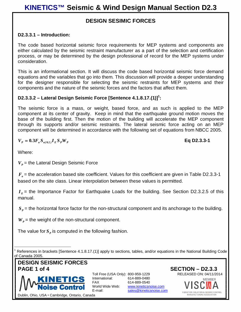
KINETICS™ Seismic & Wind Design Manual Section D2.3
DESIGN SEISMIC FORCESPAGE 1 of 4 SECTION – D2.3.3
Toll Free (USA Only): 800-959-1229 RELEASED ON: 04/11/2014International: 614-889-0480FAX 614-889-0540World Wide Web: www.kineticsnoise.comE-mail: [email protected]
Dublin, Ohio, USA Cambridge, Ontario, Canada
DESIGN SESIMIC FORCES
D2.3.3.1 – Introduction:
The code based horizontal seismic force requirements for MEP systems and components areeither calculated by the seismic restraint manufacturer as a part of the selection and certificationprocess, or may be determined by the design professional of record for the MEP systems underconsideration.
This is an informational section. It will discuss the code based horizontal seismic force demandequations and the variables that go into them. This discussion will provide a deeper understandingfor the designer responsible for selecting the seismic restraints for MEP systems and theircomponents and the nature of the seismic forces and the factors that affect them.
D2.3.3.2 – Lateral Design Seismic Force [Sentence 4.1.8.17.(1)]1:
The seismic force is a mass, or weight, based force, and as such is applied to the MEPcomponent at its center of gravity. Keep in mind that the earthquake ground motion moves thebase of the building first. Then the motion of the building will accelerate the MEP componentthrough its supports and/or seismic restraints. The lateral seismic force acting on an MEPcomponent will be determined in accordance with the following set of equations from NBCC 2005.
PPE).(aaP WSISF.V 2030 Eq D2.3.3-1
Where:
PV = the Lateral Design Seismic Force
aF = the acceleration based site coefficient. Values for this coefficient are given in Table D2.3.3-1based on the site class. Linear interpolation between these values is permitted.
EI = the Importance Factor for Earthquake Loads for the building. See Section D2.3.2.5 of thismanual.
PS = the horizontal force factor for the non-structural component and its anchorage to the building.
PW = the weight of the non-structural component.
The value for PS is computed in the following fashion.
1 References in brackets [Sentence 4.1.8.17.(1)] apply to sections, tables, and/or equations in the National Building Codeof Canada 2005.
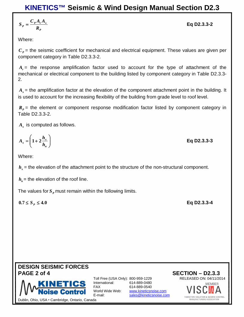
KINETICS™ Seismic & Wind Design Manual Section D2.3
DESIGN SEISMIC FORCESPAGE 2 of 4 SECTION – D2.3.3
Toll Free (USA Only): 800-959-1229 RELEASED ON: 04/11/2014International: 614-889-0480FAX 614-889-0540World Wide Web: www.kineticsnoise.comE-mail: [email protected]
Dublin, Ohio, USA Cambridge, Ontario, Canada
P
xrPP R
AACS Eq D2.3.3-2
Where:
PC = the seismic coefficient for mechanical and electrical equipment. These values are given percomponent category in Table D2.3.3-2.
rA = the response amplification factor used to account for the type of attachment of themechanical or electrical component to the building listed by component category in Table D2.3.3-2.
xA = the amplification factor at the elevation of the component attachment point in the building. Itis used to account for the increasing flexibility of the building from grade level to roof level.
PR = the element or component response modification factor listed by component category inTable D2.3.3-2.
xA is computed as follows.
n
xx h
hA 21 Eq D2.3.3-3
Where:
xh = the elevation of the attachment point to the structure of the non-structural component.
nh = the elevation of the roof line.
The values for PS must remain within the following limits.
0470 .S. P Eq D2.3.3-4
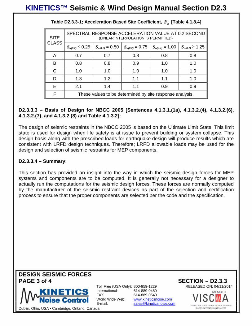
KINETICS™ Seismic & Wind Design Manual Section D2.3
DESIGN SEISMIC FORCESPAGE 3 of 4 SECTION – D2.3.3
Toll Free (USA Only): 800-959-1229 RELEASED ON: 04/11/2014International: 614-889-0480FAX 614-889-0540World Wide Web: www.kineticsnoise.comE-mail: [email protected]
Dublin, Ohio, USA Cambridge, Ontario, Canada
Table D2.3.3-1; Acceleration Based Site Coefficient, aF [Table 4.1.8.4]
SITECLASS
SPECTRAL RESPONSE ACCELERATION VALUE AT 0.2 SECOND(LINEAR INTERPOLATION IS PERMITTED)
Sa(0.2) 0.25 Sa(0.2) = 0.50 Sa(0.2) = 0.75 Sa(0.2) = 1.00 Sa(0.2) 1.25
A 0.7 0.7 0.8 0.8 0.8
B 0.8 0.8 0.9 1.0 1.0
C 1.0 1.0 1.0 1.0 1.0
D 1.3 1.2 1.1 1.1 1.0
E 2.1 1.4 1.1 0.9 0.9
F These values to be determined by site response analysis.
D2.3.3.3 – Basis of Design for NBCC 2005 [Sentences 4.1.3.1.(1a), 4.1.3.2.(4), 4.1.3.2.(6),4.1.3.2.(7), and 4.1.3.2.(8) and Table 4.1.3.2]:
The design of seismic restraints in the NBCC 2005 is based on the Ultimate Limit State. This limitstate is used for design when life safety is at issue to prevent building or system collapse. Thisdesign basis along with the prescribed loads for earthquake design will produce results which areconsistent with LRFD design techniques. Therefore; LRFD allowable loads may be used for thedesign and selection of seismic restraints for MEP components.
D2.3.3.4 – Summary:
This section has provided an insight into the way in which the seismic design forces for MEPsystems and components are to be computed. It is generally not necessary for a designer toactually run the computations for the seismic design forces. These forces are normally computedby the manufacturer of the seismic restraint devices as part of the selection and certificationprocess to ensure that the proper components are selected per the code and the specification.
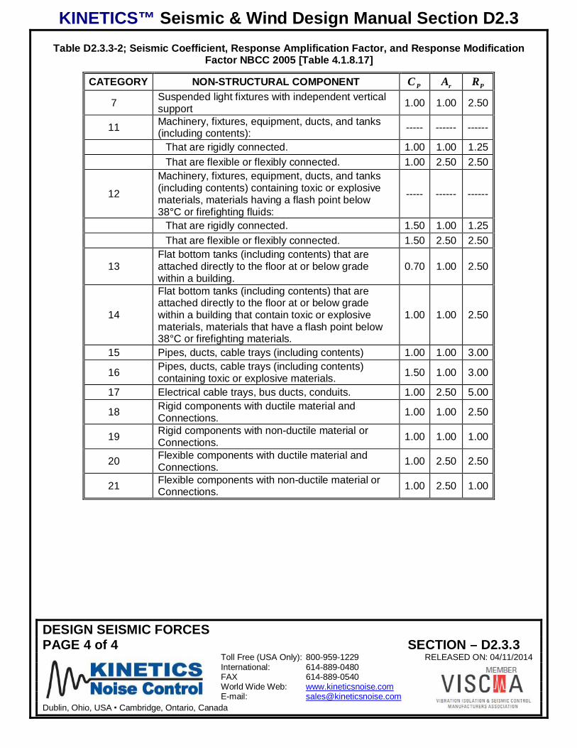
KINETICS™ Seismic & Wind Design Manual Section D2.3
DESIGN SEISMIC FORCESPAGE 4 of 4 SECTION – D2.3.3
Toll Free (USA Only): 800-959-1229 RELEASED ON: 04/11/2014International: 614-889-0480FAX 614-889-0540World Wide Web: www.kineticsnoise.comE-mail: [email protected]
Dublin, Ohio, USA Cambridge, Ontario, Canada
Table D2.3.3-2; Seismic Coefficient, Response Amplification Factor, and Response ModificationFactor NBCC 2005 [Table 4.1.8.17]
CATEGORY NON-STRUCTURAL COMPONENT PC rA PR
7 Suspended light fixtures with independent verticalsupport 1.00 1.00 2.50
11 Machinery, fixtures, equipment, ducts, and tanks(including contents): ----- ------ ------
That are rigidly connected. 1.00 1.00 1.25That are flexible or flexibly connected. 1.00 2.50 2.50
12
Machinery, fixtures, equipment, ducts, and tanks(including contents) containing toxic or explosivematerials, materials having a flash point below38°C or firefighting fluids:
----- ------ ------
That are rigidly connected. 1.50 1.00 1.25That are flexible or flexibly connected. 1.50 2.50 2.50
13Flat bottom tanks (including contents) that areattached directly to the floor at or below gradewithin a building.
0.70 1.00 2.50
14
Flat bottom tanks (including contents) that areattached directly to the floor at or below gradewithin a building that contain toxic or explosivematerials, materials that have a flash point below38°C or firefighting materials.
1.00 1.00 2.50
15 Pipes, ducts, cable trays (including contents) 1.00 1.00 3.00
16 Pipes, ducts, cable trays (including contents)containing toxic or explosive materials. 1.50 1.00 3.00
17 Electrical cable trays, bus ducts, conduits. 1.00 2.50 5.00
18 Rigid components with ductile material andConnections. 1.00 1.00 2.50
19 Rigid components with non-ductile material orConnections. 1.00 1.00 1.00
20 Flexible components with ductile material andConnections. 1.00 2.50 2.50
21 Flexible components with non-ductile material orConnections. 1.00 2.50 1.00
KINETICS™ Seismic & Wind Design Manual Section D2.3
GENERAL EXEMPTIONS AND REQUIREMENTSPAGE 1 of 3 SECTION – D2.3.4
Toll Free (USA Only): 800-959-1229 RELEASED ON: 04/11/2014International: 614-889-0480FAX 614-889-0540World Wide Web: www.kineticsnoise.comE-mail: [email protected]
Dublin, Ohio, USA Cambridge, Ontario, Canada
GENERAL EXEMPTIONS AND REQUIREMENTS
D2.3.4.1 – Introduction:
The National Building Code of Canada has limited exemptions for MEP components written in toit. The SMACNA Seismic Restraint Manual – Guidelines for Mechanical Systems, 2nd Edition withAddendum No. 1, 1998; is not directly referenced in the NBCC. Therefore, it is safe to assumethat any exemptions in the SMACNA manual that have been previously taken are no longerallowed.
There are, however, some general exemptions for MEP components which will be covered in thissection. Along with the exemptions, this section will the requirements for flexible/flexibly connected(isolated) components, direction of seismic design force application, structural connections,deflections, transfer of seismic forces to the building structure, and hanger rods for MEPcomponents.
D2.3.4.2 - General Acceleration Based Exemption for MEP Components [Sentences 4.1.8.1,and 4.1.8.17.(2)]1
Sentence 4.1.8.1 is a general exemption for building, and also applies to those buildings that havebeen assigned to the Importance Category classified as Post Disaster. The deflections and loadsdue to earthquake motion as specified in Sentence 4.1.8.17, do not apply to MEP Componentswhen 12020 .S ).(a . Under this condition seismic restraints will not be required for MEPcomponents.
The next general exemption is found in Sentence 4.1.8.17.(2) and applies to buildings that havebeen assigned to Importance Categories Low, Normal, and High. Section D2.3.3 of this manualcovered the seismic design forces specified by the NBCC. The basic acceleration term multiplyingthe weight (mass) of the MEP component is ).(aaE SFI 20 . This term includes the importance of thebuilding, the effects of the ground upon which the project is being built, and the expectedhorizontal acceleration produced by the design earthquake for the project location. This generalexemption for MEP components is based on the value of this term. If 35020 .SFI ).(aaE , then MEPcomponents that fall into categories 7 through 21 in Table D2.3.3-2 of this manual do not requireseismic restraint for buildings assigned to Importance Categories Low, Normal, and High.
1 References in brackets [Sentence 4.1.8.17.(2)] apply to sections, tables, and/or equations in the National Building Codeof Canada 2005.
KINETICS™ Seismic & Wind Design Manual Section D2.3
GENERAL EXEMPTIONS AND REQUIREMENTSPAGE 2 of 3 SECTION – D2.3.4
Toll Free (USA Only): 800-959-1229 RELEASED ON: 04/11/2014International: 614-889-0480FAX 614-889-0540World Wide Web: www.kineticsnoise.comE-mail: [email protected]
Dublin, Ohio, USA Cambridge, Ontario, Canada
D2.3.4.3 – “Chandelier” Exemption [Sentence 4.1.8.17.(13)]
This exemption does not read exactly as the companion exemption in the International BuildingCode (IBC); see Kinetic’s Guide to Understanding IBC Seismic for MEP, Section D2.1.4.5. So, forclarity it will be directly quoted below.
Isolated suspended equipment and components, such as pendant lights, may be designed as apendulum system provided that adequate chains or cables capable of supporting 2.0 times the weight ofthe suspended component are provided and the deflection requirements of Sentence 4.1.8.17.(11) aresatisfied.
D2.3.4.4 – Isolated vs. Rigidly Connected Components [Sentence 4.1.8.17.(4)]:
The NBCC basically says that MEP components that can be defined by Categories 11 and 12 inTable D2.3.3-2 of this Guide are to be treated as flexible/flexibly connected (isolated) components.If, however, the fundamental period of the component and its connections to the building structurecan be shown to be less than or equal to 0.06 second, it mat be treated as though it were a rigidor rigidly connected component.
D2.3.4.5 – Design Horizontal Seismic Load Application [Sentence 4.1.8.17.(7)]:
The design horizontal seismic loads are to be applied in the direction the results in the mostcritical loading for the MEP component and its attachment to the structure. This will ensure thatthe most conservative design and selection of seismic restraints for the MEP component has beenmade.
D2.3.4.6 – Connection of MEP Components to the Building Structure [Sentence4.1.8.17.(8)]:
Connections for the MEP components to the building structure must be designed to resist gravityloads, meet the requirements of Sentence 4.1.8.1 of the NBCC, and also satisfy the followingadditional requirements.
1. Friction due to gravity loads may not be used to resist seismic forces.2. The PR value for non-ductile fasteners such as adhesives, powder shot pins, and other power
actuated fasteners must be taken as 1.0.3. Shallow embedment anchors, shallow expansion, chemical, epoxy, or cast-in-place, are
those whose embedment depth to nominal diameter ratio is less than 8:1. For these types ofanchors the value for PR shall be taken as 1.5.
4. Drop in anchors and power actuated fasteners, such as powder shot pins, are not to be usedin tensile applications.
KINETICS™ Seismic & Wind Design Manual Section D2.3
GENERAL EXEMPTIONS AND REQUIREMENTSPAGE 3 of 3 SECTION – D2.3.4
Toll Free (USA Only): 800-959-1229 RELEASED ON: 04/11/2014International: 614-889-0480FAX 614-889-0540World Wide Web: www.kineticsnoise.comE-mail: [email protected]
Dublin, Ohio, USA Cambridge, Ontario, Canada
D2.3.4.7 – Lateral Deflections of MEP Components [Sentence 4.1.8.17.(10)]:
The lateral deflections based on design horizontal seismic force specified the Sentence4.1.8.17.(1), see Section D2.3.3 of this manual, need to be multiplied by a factor of EP IR to yieldmore realistic values for the anticipated deflections. The values of PR and EI are used to artificiallyinflate the loads to ensure the selection of seismic restraints and attachments that will meet thePost-Disaster criteria.
D2.3.4.8 – Transfer of Seismic Restraint Forces [Sentence 4.1.8.17.(11)]:
This provision is intended to engender co-operation between the MEP design professionals andthe structural engineering professionals. It is basically saying that the MEP components and theirattachments to the building structure must be designed in such away that they do not transfer anyloads to the structure that were not anticipated by the structural engineer. This means that theMEP design professionals must inform the structural engineer of the anticipated dead loads andseismic restraint forces at the restraint attachment points as soon as the MEP componentselections have been finalized. Conversely, the structural engineer needs to make him or her selfavailable to the MEP design professionals to work out issues surrounding the seismic loads andthe attachment points for the seismic restraints used for the MEP components.
D2.3.4.9 – Seismic Restraints for Suspended MEP Components & Hanger Rods [Sentence4.1.8.17.(12)]:
The seismic restraints for suspended MEP equipment, pipes, ducts, electrical cable trays, busducts, and so on, must meet the force and displacement conditions of Sentence 4.1.8.17, and bedesigned in such away that they do not place the hanger rods in bending.
D2.3.4.13 - Summary:
The exemptions and requirements outlined in this section are intended to assist the MEP designprofessionals and contractors in planning their project contribution efficiently. Also, they helpdefine the limits of responsibility for each MEP design profession and trade.
KINETICS™ Seismic & Wind Design Manual Section D2.5.1
INTRODUCTIONPAGE 1 of 1 SECTION – D2.5.1
Toll Free (USA Only): 800-959-1229 RELEASED ON: 04/11/2014International: 614-889-0480FAX 614-889-0540World Wide Web: www.kineticsnoise.comE-mail: [email protected]
Dublin, Ohio, USA Cambridge, Ontario, Canada
UFC ANTI-TERRORISM
D2.5.1 – Introduction:
The United States Department of Defense has developed a set of standards for the design of newand existing buildings. These are called Unified Facilities Criteria (UFC). For seismic and windrestraint, and antiterrorism provisions for nonstructural components are found in three separateUFC documents which are listed below.
1. UFC-3-310-04 Dated 22 June 2007 Including Change Dated 01 May 2012 SESISMICDESIGN FOR BUILDINGS.
2. UFC-3-301-01 Dated 27 January 2010 STRUCTURAL ENGINEERING.
3. UFC-4-010-01 Dated 8 October 2003 Including Change Dated 22 January 2007 DoDMINIMUM ANTITERRORISM STANDARDS FOR BUILDINGS.
These documents are available via the internet. They may be down loaded in PDF format by“GOOGLING” the UFC number.
This document will deal with each of the sub-headings one at a time. Antiterrorism will be the firstsub-heading discussed since it seems to show up in specifications more often than the other two.Also, the provisions for restraint in the antiterrorism standard will “trump” those of the seismicdesign standard if the design acceleration level for the seismic design falls below that required forthe antiterrorism standard.
KINETICS™ Seismic & Wind Design Manual Section D2.5.2
UFC-4-010-01 ANTITERRORISMPAGE 1 of 2 SECTION – D2.5.2
Toll Free (USA Only): 800-959-1229 RELEASED ON: 04/11/2014International: 614-889-0480FAX 614-889-0540World Wide Web: www.kineticsnoise.comE-mail: [email protected]
Dublin, Ohio, USA Cambridge, Ontario, Canada
UFC-4-010-01 ANTITERRORISM
D2.5.2 - UFC-4-010-01:Only one Section B-4.5 – Standard 20. Equipment Bracing of this document will apply to therestraint of MEP (Mechanical, Electrical, and Plumbing) components. It is quoted in its entiretybelow.
Mount all overhead utilities and other fixtures weighing 14 kilograms (31 pounds) or more (excludingdistributed systems such as piping networks that collectively exceed that weight) to minimize the likelihoodthat they will fall and injure building occupants. Design all equipment mountings to resist forces of 0.5 timesthe equipment weight in any horizontal direction and 1.5 times the equipment weight in the downwarddirection. This standard does not preclude the need to design equipment mountings for forces required byother criteria such as seismic standards.
Piping, ductwork, cable trays, conduit, and bus bars appear to be exempt from the provisions ofthis standard. The reasoning appears to be that distributed systems such as these will have manyhangers supporting them. Equipment, on the other hand, will have only four or perhaps sixhangers. Losing one or two hangers in a distributed system would not be likely to bring down theentire system, whereas, losing one or two hangers on a piece of equipment would pretty muchguarantee that it would fall.
Some specifications do impose the provisions of this standard on piping and ductwork. In thesecases the following items need to be considered.
All hangers and their anchors will need to be evaluated for the increased vertical loads mandatedby this standard. That is the deadweight of the pipe or duct plus 0.5 times the deadweight of thepipe or duct.
The hanger spacing and the restraint spacing may need to be reduced to protect the pipe or ductfrom the increased vertical and horizontal loads mandated by this standard.
The first sentence of the standard indicates that it applies only to overhead equipment andfixtures. These components will need to be braced to resist 0.5 time the deadweight of theequipment (0.5 G) horizontally in any direction and 0.5 times the deadweight of the equipmentplus the deadweight of the equipment (1.5 G total) in the downward direction. The secondsentence says that all equipment must be braced to this standard. However the 1.5 G totaldownward would seem to indicate that only suspended equipment and fixtures are covered underthis standard. So, a clear interpretation of that provision will need to come from the specificationand/or the Engineer of Record.
In many buildings where UFC 4-010-01 is specified, seismic restraint of MEP components maynot be required by the building code. This horizontal restraint requirement of this standard will“trump” the seismic restraint requirements of the code up to the point where the coderequirements exceed the 0.5 G horizontal load specified by this standard. A careful reading of the
KINETICS™ Seismic & Wind Design Manual Section D2.5.2
UFC-4-010-01 ANTITERRORISMPAGE 2 of 2 SECTION – D2.5.2
Toll Free (USA Only): 800-959-1229 RELEASED ON: 04/11/2014International: 614-889-0480FAX 614-889-0540World Wide Web: www.kineticsnoise.comE-mail: [email protected]
Dublin, Ohio, USA Cambridge, Ontario, Canada
specification will be needed to obtain the proper interpretation of this standard for a project, andto see what if any components have been made exempt from the provisions of this standard.
KINETICS™ Seismic & Wind Design Manual Section D2.5
UFC-3-310-04 SEISMIC & UFC-3-301-01 STRUCTURALPAGE 1 of 4 SECTION – D2.5.3
Toll Free (USA Only): 800-959-1229 RELEASED ON: 04/11/2014International: 614-889-0480FAX 614-889-0540World Wide Web: www.kineticsnoise.comE-mail: [email protected]
Dublin, Ohio, USA Cambridge, Ontario, Canada
UFC-3-310-04 SEISMIC DESIGN & UFC-3-301-01 STRUCTURAL ENGINEERING
D2.5.3.1 – Introduction
This standard is a replacement for TI 809-04 and TI 809-05. It adopts the seismic designprovisions of 2003 IBC and ASCE 7-02, with some modification. This standard is meant to work inconjunction with UFC 3-301-01 Structural Engineering. UFC 3-301-01 has adopted the provisionsof 2006 IBC and ASCE 7-05. Some of the provisions of ASCE 7-02 in UFC 3-310-04 have beenreplaced by the provisions of ASCE 7-05. If this seems confusing, it is. This document will attemptto cover the provisions that apply to MEP components and concisely as possible.
D2.5.3.2 – Building Occupancy:
UFC 3-301-01 uses Occupancy Category to classify buildings and structures in a manner similarto 2006 IBC. However, it adds a fifth occupancy category for national strategic military assets.These are buildings that are considered to be irreplaceable and must be kept functioning at allcosts. The example given was National Missile Defense facilities. UFC 3-310-04 still uses theSeismic Use Group (SUG) to classify buildings and structures. It adds a fourth SUG thatcorresponds to the fifth Occupancy Category of UFC 3-301-01. Occupancy Category and SUG willbe defined below. For detailed examples of each refer to UFC 3-301-01 Table 2-2.
1. SUG I (Occupancy Categories I & II) – Buildings and other structures that represent a lowhazard to human life in the event of failure.
2. SUG II (Occupancy Category III) – Buildings and other structures that represent a substantialhazard to human life or represent a significant economic loss in the event of failure.
3. SUG III (Occupancy Category IV) – Buildings and other structures designed as essentialfacilities.
4. SUG IV (Occupancy Category V) – Facilities designed as national strategic military assets.
D2.5.3.3 – Design for Wind Loads:
The design for wind loading of exterior exposed MEP components will be per 2003 IBC and ASCE7-02. The 3-sec gust design wind speed may be found in UFC 3-301-01 Table E-1 for installationsin the United States, its territories, and possessions. For facilities located outside the UnitedStates, its territories, and possessions, the 3-sec gust design wind speed may be found in UFC 3-301-01 Table F-1. The Wind Importance Factor, WI , will depend on the Occupancy Category ofthe building or structure as shown in Table D2.5.3-1.
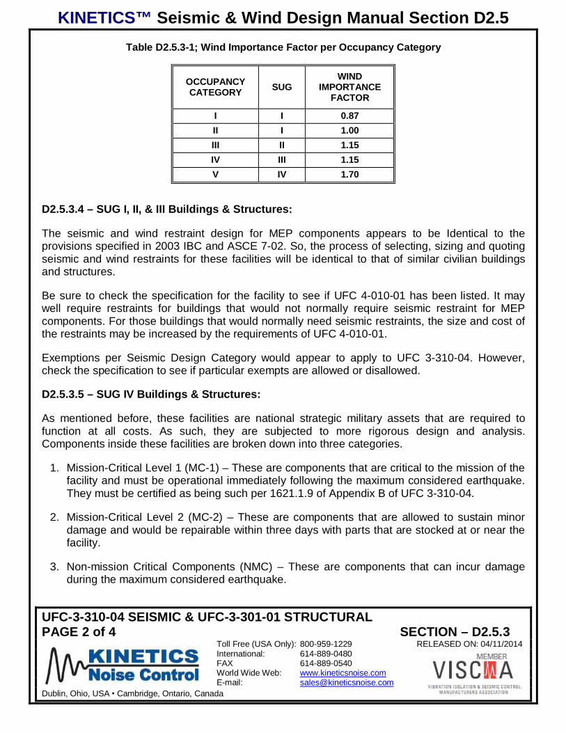
KINETICS™ Seismic & Wind Design Manual Section D2.5
UFC-3-310-04 SEISMIC & UFC-3-301-01 STRUCTURALPAGE 2 of 4 SECTION – D2.5.3
Toll Free (USA Only): 800-959-1229 RELEASED ON: 04/11/2014International: 614-889-0480FAX 614-889-0540World Wide Web: www.kineticsnoise.comE-mail: [email protected]
Dublin, Ohio, USA Cambridge, Ontario, Canada
Table D2.5.3-1; Wind Importance Factor per Occupancy Category
OCCUPANCYCATEGORY SUG
WINDIMPORTANCE
FACTOR
I I 0.87II I 1.00III II 1.15IV III 1.15V IV 1.70
D2.5.3.4 – SUG I, II, & III Buildings & Structures:
The seismic and wind restraint design for MEP components appears to be Identical to theprovisions specified in 2003 IBC and ASCE 7-02. So, the process of selecting, sizing and quotingseismic and wind restraints for these facilities will be identical to that of similar civilian buildingsand structures.
Be sure to check the specification for the facility to see if UFC 4-010-01 has been listed. It maywell require restraints for buildings that would not normally require seismic restraint for MEPcomponents. For those buildings that would normally need seismic restraints, the size and cost ofthe restraints may be increased by the requirements of UFC 4-010-01.
Exemptions per Seismic Design Category would appear to apply to UFC 3-310-04. However,check the specification to see if particular exempts are allowed or disallowed.
D2.5.3.5 – SUG IV Buildings & Structures:
As mentioned before, these facilities are national strategic military assets that are required tofunction at all costs. As such, they are subjected to more rigorous design and analysis.Components inside these facilities are broken down into three categories.
1. Mission-Critical Level 1 (MC-1) – These are components that are critical to the mission of thefacility and must be operational immediately following the maximum considered earthquake.They must be certified as being such per 1621.1.9 of Appendix B of UFC 3-310-04.
2. Mission-Critical Level 2 (MC-2) – These are components that are allowed to sustain minordamage and would be repairable within three days with parts that are stocked at or near thefacility.
3. Non-mission Critical Components (NMC) – These are components that can incur damageduring the maximum considered earthquake.
KINETICS™ Seismic & Wind Design Manual Section D2.5
UFC-3-310-04 SEISMIC & UFC-3-301-01 STRUCTURALPAGE 3 of 4 SECTION – D2.5.3
Toll Free (USA Only): 800-959-1229 RELEASED ON: 04/11/2014International: 614-889-0480FAX 614-889-0540World Wide Web: www.kineticsnoise.comE-mail: [email protected]
Dublin, Ohio, USA Cambridge, Ontario, Canada
These designations apparently replace the Component Importance Factor that would normally beassigned to the MEP components in the facility.
The seismic forces specified for MC-1, MC-2 MEP components in ASCE 7-02 do not apply toSUG IV facilities. The response spectrum, acceleration, is computed using ASCE 4-98, and theactual forces are computed per equation E-15 of UFC 3-310-04. The seismic forces for the NMCMEP components are calculated using the normal equations found in ASCE 7-02.
Quoting restraints for SUG IV facilities will require close coordination with the Structural Engineerof Record, and the Architect of Record to ensure that the proper designation is assigned to eachcomponent and that the proper seismic parameters are transmitted to Kinetics Noise Control.
Carefully reading the specification will indicate whether any exemptions may be applied to pipingand ductwork. Also the specification will indicate whether additional safety factors will be required.
D2.5.3.6 – Ground Acceleration Values:
The values of SS and 1S for installations that lie within the United States may be obtained formTable E-2 of UFC 3-301-01, and for installations that lie outside the United States, the values for
SS and 1S may be obtained from Tables F-2 and G-1 of UFC 3-301-01. These values should alsobe available in the specification and on the first sheet of the structural drawing package. In theprovisions for SUG III & IV buildings more stringent values for SS and 1S may be required.
D2.5.3.7 – Component Importance Factor:
For SUG I, II, and III facilities, the Component Importance Factor is assigned to MEP components,unless UFC 3-310-04 Appendix D is used for the design of an SUG III facility. The ComponentImportance Factor will be either 1.0 or 1.5 similar to 2003 IBC. If Appendix D is used for thedesign of SUG III facilities, no Component Importance Factors will be assigned to MEPcomponents. This is because the acceleration factors used to compute the seismic forces are 1.5times greater than those normally used for 2003 IBC. So, if Appendix D is referenced for thedesign of an SUG III facility treat all components as if they had a Component Importance Factorequal to 1.5.
As seen in Section D2.5.3.5 of this document, SUG IV facilities will not have ComponentImportance Factors assigned to the MEP Components.
D2.5.3.8 – SMACNA:
SMACNA is directly referenced in UFC 3-310-04. However, it is the new SMACNA seismicmanual that is referenced.
KINETICS™ Seismic & Wind Design Manual Section D2.5
UFC-3-310-04 SEISMIC & UFC-3-301-01 STRUCTURALPAGE 4 of 4 SECTION – D2.5.3
Toll Free (USA Only): 800-959-1229 RELEASED ON: 04/11/2014International: 614-889-0480FAX 614-889-0540World Wide Web: www.kineticsnoise.comE-mail: [email protected]
Dublin, Ohio, USA Cambridge, Ontario, Canada
ANSI/SMACNA 001-2008 Seismic Restraint Manual, Guidelines for Mechanical Systems 3rd
Edition; Sheet Metal and Air Conditioning Contractors’ National Association, 4201 LafayetteCenter Drive, Chantilly, Virginia 20151-1219.
This has consequences for the engineers and contractors since this version of the SMACNAmanual does not allow the 6 ft2 exemption for ducts assigned a Component Importance Factor of1.5. Thus for SUG III & IV buildings there will be no exemptions for ductwork, and everything willneed to be restrained. Again, it is important to check the specification to see if it will allow the sizeexemptions for ductwork.
D2.5.3.9 – Inspections:
Walk-down inspections are required for all MEP components in all SUG III and IV facilities as wellas all facilities assigned to Seismic Design Categories D, E, and F, prior to facility commissioning.The inspectors are to be registered design professionals who are familiar with the constructionand installation of MEP components. The selection of these inspectors must be approved by theheadquarters of the authorizing design agency. While this inspection is to be carried out a specialselected team of design professionals, representatives from Kinetics Noise Control may berequired to participate per the specification. Therefore, any quotations to supply restraints shouldinclude the cost of time and travel to cover the inspection(s).

KINETICS™ Seismic & Wind Design Manual Section D2.5
SUMMARYPAGE 1 of 2 SECTION – D2.5.4
Toll Free (USA Only): 800-959-1229 RELEASED ON: 04/11/2014International: 614-889-0480FAX 614-889-0540World Wide Web: www.kineticsnoise.comE-mail: [email protected]
Dublin, Ohio, USA Cambridge, Ontario, Canada
UFC ANTITERRORISM
D2.5.4 – Summary:
1. UFC 4-010-01 (Antiterrorism) appears to apply only to equipment. Piping and ductwork areexcluded. Check the specification to see if piping and ductwork have been included under theprovisions of this UFC, occasionally they are.
2. UFC 4-010-01 mentions suspended equipment, and then states that all equipment is to bebraced. Check the specification to see if floor and roof mounted equipment is included forconsideration.
3. UFC 4-010-01 requires that equipment be braced to withstand 0.5 G in any horizontaldirection and 1.5 G total in the downward direction. This requirement will “trump” the seismicprovisions of UFC 3-310-04 up to the point where they exceed 0.5 G.
4. UFC 3-301-01 (Structural Engineering) Table 2-2 defines the Building Occupancy Categoriesused in the UFC standards. A new Building Occupancy Category (V) has been established;see Section 3.1 of this document.
5. UFC 3-301-01 (Structural Engineering) Table E-1 will give the 3-sec gust design wind speedfor facilities in the United States, its territories, and possessions. While Table F-1 will give the3-sec gust design wind speed for facilities outside the United States, its territories, andpossessions.
6. UFC 3-301-01 (Structural Engineering) Table E-2 will give the seismic data for facilities in theUnited States, its territories, and possessions.
7. UFC 3-301-01 (Structural Engineering) Tables F-2 and G-1 will give the seismic data forfacilities outside the United States, its territories, and possessions.
8. UFC 3-310-04 (Seismic Design) is based on the provisions of 2003 IBC (ASCE 7-02).
9. UFC 3-310-04 (Seismic Design) establishes a new Seismic Use Group (SUG), see SectionD2.5.3.1 of this document.
10. For SUG I, II, and III facilities, the seismic restraint of MEP components is carried out in amanner similar to 2003 IBC (ASCE 7-02). The exception would be if the design of an SUG IIIfacility was specified as using UFC 3-310-04 Appendix D, see section D2.5.3.7 of thisdocument.
11. SUG IV facilities will require special consideration and design for the seismic restraints forMEP components. Contact Kinetics Noise Control before quoting the seismic restraints for afacility designate as SUG IV or Occupancy Category V.
KINETICS™ Seismic & Wind Design Manual Section D2.5
SUMMARYPAGE 2 of 2 SECTION – D2.5.4
Toll Free (USA Only): 800-959-1229 RELEASED ON: 04/11/2014International: 614-889-0480FAX 614-889-0540World Wide Web: www.kineticsnoise.comE-mail: [email protected]
Dublin, Ohio, USA Cambridge, Ontario, Canada
12. It is important to obtain and read the specification for all Department of Defense facilities orother facilities that reference UFC 4-010-01 or UFC 3-310-04.
a. The specifications will indicated the exact design standards being employed.
b. The specifications may increase the requirements beyond the UFC standards. Theymay require that UFC-4-010-01 be applied to floor and roof mounted equipment, andalso to piping and ductwork. They specifications may also increase the minimumsafety factor, sometimes to 3:1 or even 4:1. This will significantly affect the numberand size of restraints required.
c. The specification will indicate whether representatives from Kinetics Noise Control areto participate in the mandated walk-down inspections of SUG III and IV facilities. Also,walk-down inspections appear to be required for all facilities assigned to SeismicDesign Categories D, E, and F. Quotations to supply seismic restraints to theseprojects must include the cost of time and travel for the inspections.
d. Finally, the specifications may indicate the exemptions that will apply to piping,ductwork and electrical distribution systems.
13. Note that the Wind Importance Factor for Occupancy V facilities has been raised to 1.7,which means that more restraint is required for exposed outside equipment.