kisssoft 03/2012 – tutorial 4 · kisssoft 03/2012 – tutorial 4 bolt calculation according to...
TRANSCRIPT
KISSsoft 03/2012 – Tutorial 4
Bolt calculation according to VDI 2230
KISSsoft AG Uetzikon 4 8634 Hombrechtikon Switzerland Tel: +41 55 254 20 50 Fax: +41 55 254 20 51 [email protected] www.KISSsoft.AG

27.03.2012 2 / 12
Contents
1 Starting KISSsoft ...................................................................................................................................... 3 1.1 Starting the software ....................................................................................................................... 3 1.2 Selecting a calculation .................................................................................................................... 3
2 Calculation of a flanged connection ......................................................................................................... 4 2.1 Task ................................................................................................................................................ 4 2.2 Proposal for a reasonable bolt diameter ......................................................................................... 5 2.3 Definition of nuts and washers ....................................................................................................... 5 2.4 Definition of clamped parts ............................................................................................................. 6 2.5 Definition of the bolt ........................................................................................................................ 7
3 Analysis and results ................................................................................................................................. 8 3.1 Performing the analysis, report ....................................................................................................... 8 3.2 Comments on the results .............................................................................................................. 10
4 Further Calculations ............................................................................................................................... 10 4.1 Analysis with a smaller bolt .......................................................................................................... 10 4.2 Constraints, settings ..................................................................................................................... 11

27.03.2012 3 / 12
1 Starting KISSsoft
1.1 Starting the software
You can call KISSsoft as soon as the software has been installed and activated. Usually you start the program by clicking "StartProgram FilesKISSsoft 03-2012KISSsoft". This opens the following KISSsoft user interface:
Figure 1. Starting KISSsoft, initial window
1.2 Selecting a calculation
In the Modules tree window, select the "Modules" tab to call the bolt calculation module:
Figure 2. Selecting the "Bolts" calculation module

27.03.2012 4 / 12
2 Calculation of a flanged connection
2.1 Task
Size and verify the bolting for a flanged coupling using the following data:
Torque to be transmitted 13 kNm Pitch diameter 258 mm Number of bolts on pitch circle 12 Material flange (left/right) EN-GJL-250 (GG25)/34CrNiMo6 Thickness flange (left/right) 22 mm/18 mm Flange surface (left/right) N7/N8 Flange outer diameter 320 mm
Flange inner diameter 210 mm Coefficient of friction 0.15 Axial force lower value 0 kN Axial force upper value 10 kN Bolt strength class 10.9 Type: hexagon headed bolt with shank (AB) EN ISO 4014, Tightening: with torque wrench
The connection is made using through bolts (notation as specified in VDI 2230:2003 - bolted joint) with nuts, and with washers under the nuts and under the bolt head. If you require a different unit of measurement, click the right-hand mouse button on the unit you want to change to open the corresponding selection list. You can then simply select the unit you want from this list and change the units used in the calculation. Input this data in the "Basic data" tab as follows:
Figure 3. Inputting known data, selecting the calculation method

27.03.2012 5 / 12
2.2 Proposal for a reasonable bolt diameter
After you have defined the load, and input the basic data for the bolt, click the "Sizing button" in the main window. The program proposes values for a suitable bolt diameter. This proposal is based on a simplified bolt layout as specified in VDI 2230:2003. This method usually results in over-dimensioned bolts. Experience shows that the minimum permitted bolt diameter is often one or two sizes lower! Note the message that appears when you click the Sizing button. When you click the Sizing button, the software suggest a reference diameter based on VDI 2230: 2003, in this case, M22.
Figure 4. Sizing the bolt diameter
Figure 5. Message indicating that the proposed bolt diameter may be too large
You can reduce the reference diameter to 16mm manually:
Figure 6. Reference bolt diameter set manually to 16mm
2.3 Definition of nuts and washers
In the "Basic data" tab you can now input the data for the nuts and washers:
Figure 7. Calling the subscreens for defining washers and nuts
27.03.2012 6 / 12
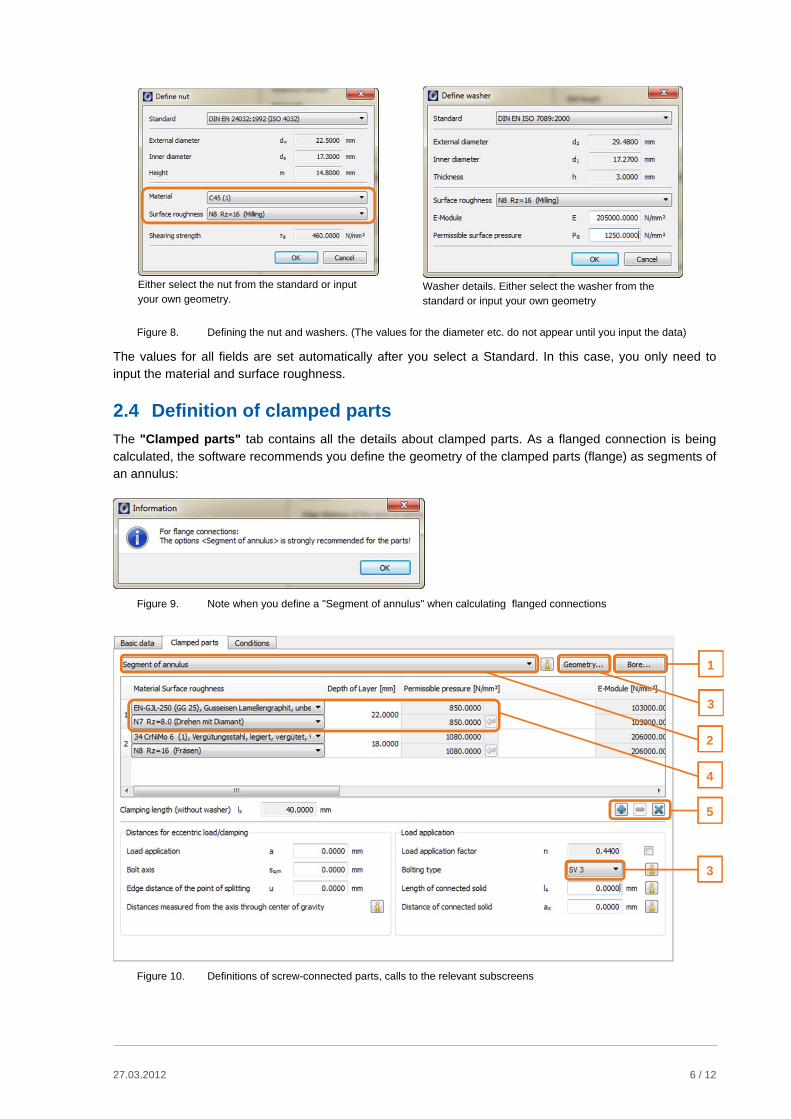
Either select the nut from the standard or input your own geometry.
Washer details. Either select the washer from the standard or input your own geometry
Figure 8. Defining the nut and washers. (The values for the diameter etc. do not appear until you input the data)
The values for all fields are set automatically after you select a Standard. In this case, you only need to input the material and surface roughness.
2.4 Definition of clamped parts
The "Clamped parts" tab contains all the details about clamped parts. As a flanged connection is being calculated, the software recommends you define the geometry of the clamped parts (flange) as segments of an annulus:
Figure 9. Note when you define a "Segment of annulus" when calculating flanged connections
Figure 10. Definitions of screw-connected parts, calls to the relevant subscreens
4
2
3
1
5
3
27.03.2012 7 / 12
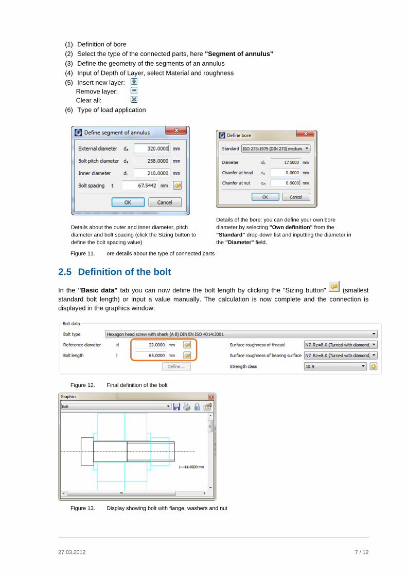
(1) Definition of bore
(2) Select the type of the connected parts, here "Segment of annulus"
(3) Define the geometry of the segments of an annulus
(4) Input of Depth of Layer, select Material and roughness
(5) Insert new layer: Remove layer: Clear all:
(6) Type of load application
Details about the outer and inner diameter, pitch diameter and bolt spacing (click the Sizing button to define the bolt spacing value)
Details of the bore: you can define your own bore diameter by selecting "Own definition" from the "Standard" drop-down list and inputting the diameter in the "Diameter" field.
Figure 11. ore details about the type of connected parts
2.5 Definition of the bolt
In the "Basic data" tab you can now define the bolt length by clicking the "Sizing button" (smallest standard bolt length) or input a value manually. The calculation is now complete and the connection is displayed in the graphics window:
Figure 12. Final definition of the bolt
Figure 13. Display showing bolt with flange, washers and nut

27.03.2012 8 / 12
3 Analysis and results
3.1 Performing the analysis, report
This predefines all the data so you can verify the connection. To do this, click the icon (1) in the command bar (or press F5). The most important results are displayed in the "Results" window. To call the
detailed report, either press F6 or click the icon (2). To return from the report to the analysis, click the
icon in the tool bar. Make selections from the selection list to change the graphic (screw) displayed here down on the right-hand side.
Figure 14. Running the calculation, resulting bolt geometry, results overview
2 1

27.03.2012 9 / 12
You can also display more graphics by clicking the "Graphics" menu option:
Figure 15. Display containing other graphics
Figure 16. Displaying the report and changes to the displayed graphic

27.03.2012 10 / 12
3.2 Comments on the results
Results displayed in the main window:
Pretension force (N), alphaA=1, alphaA eff
Indicates the pretension force required to ensure the connection will withstand shear forces. Both the minimum value (tightening factor=1) and the maximum value (tightening factor=1.6, in this example) are shown.
Starting torque (Nm), alphaA=1, alphaA eff
Information about the tightening torque achieved, minimum value (tightening factor=1) and also maximum value (tightening factor=1.6, in this example).
Bolt safety Safety factor against yield point
Pressure safety Minimum safety factor of surface pressure
Alternating load safety Safety factor against fatigue of bolt
Results shown in the report, "Calculating safeties with the maximum required mounting pretension force" section:
Mounting pretension force (N) [FM]
In addition to the required pretension force (see table above), the report also lists the mounting pretension force. This value corresponds to the values for tightening torque specified in Appendix A of VDI2230
Tightening torque (Nm) [MA] Value for tightening torque. This value corresponds to the values for tightening torque specified in Appendix A of VDI2230
4 Further Calculations
4.1 Analysis with a smaller bolt
Finally, you should check whether M16 is the smallest possible bolt diameter. To do this, reduce the bolt diameter to M14 and then repeat the calculation. The message tells you that a connection using a M14 bolt is not mathematically possible.
Figure 17. Input new bolt diameter, -> run calculation, -> error message

27.03.2012 11 / 12
4.2 Constraints, settings
You can input more values for the calculation in the input window in the "Entries" tab, and in the "Calculations/Settings" menu option. However, this requires a detailed knowledge of VDI guideline 2230:2003.
Figure 18. Module-specific settings
The critical values in the calculation are the assumed coefficients of friction between the thread and thread hole and between the head/nut and clamped part. You must input these values in the "Entries" tab. The
VDI guideline proposes a number of different friction coefficients. Click the "Info buttons" to display these in the information window.
Figure 19. Settings used to perform a calculation according to VDI 2230 in the "Conditions" tab

27.03.2012 12 / 12
You can also specify the tightening factor in the "Basic data" tab.
Figure 20. Tightening factor in Basic data