klik digital - hager · klik digital the klik digital connection system (kdcs) is a marshalling box...
TRANSCRIPT

10.0
Klik Digital
The Klik Digital Connection System (KDCS) is a marshalling box capable of distributing power and data to 4, 6, 8, or 10 digital ballasts.
KDCS can be sub-divided into two circuits for greater flexibility. Klik Digital plugs connect the luminaires to the KDCS marshalling box, a blue five pin plug for non emergency luminaires and a red auxiliary plug for emergency luminaires. All plugs are factory pre-wired with a bespoke cable that combines the power and data cables together but allows them to be separated by a double insulation.
High performance, programmable presence detectors that monitor and regulate the lighting level.
For lighting specialists who already install lighting management systems the KDCS can be used as part of a larger system in terms of the distribution box.
Presence detection is by passive infrared effectively enhanced to improve sensitivity to small movements.
Regulating photocell ensures a minimum maintained light level, taking account of the contribu-tion from adjacent luminaires and daylight.
Incorporates simple scene set-ting, up to six scenes can be set via user remote.
Off delay in minutes following the last observed movement after which the lights switch off/dim down.
Klik
D
igita
l
10.1
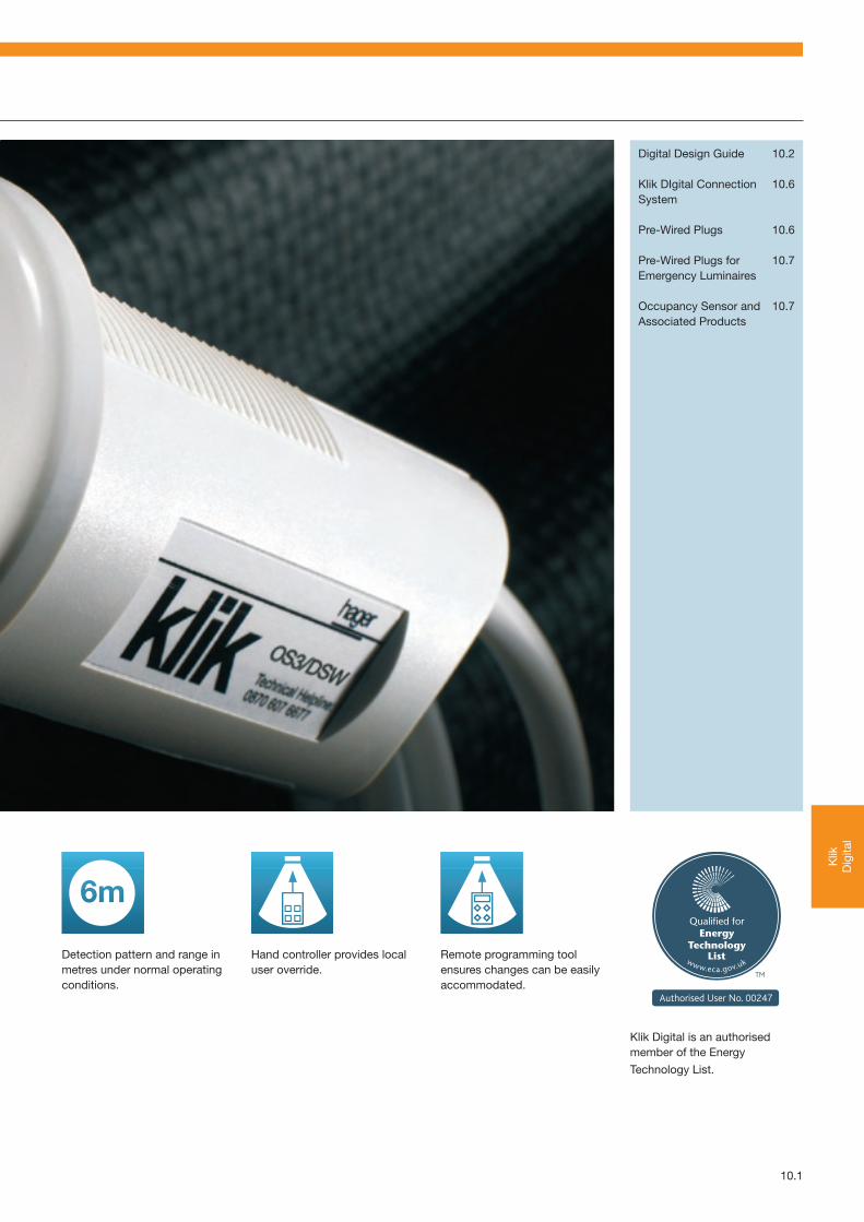
Digital Design Guide 10.2
Klik DIgital Connection 10.6System
Pre-Wired Plugs 10.6
Pre-Wired Plugs for 10.7Emergency Luminaires
Occupancy Sensor and 10.7Associated Products
Detection pattern and range in metres under normal operating conditions.
Hand controller provides local user override.
Remote programming tool ensures changes can be easily accommodated.
Klik Digital is an authorised member of the Energy
Technology List.
10.2
Digital Design Guide
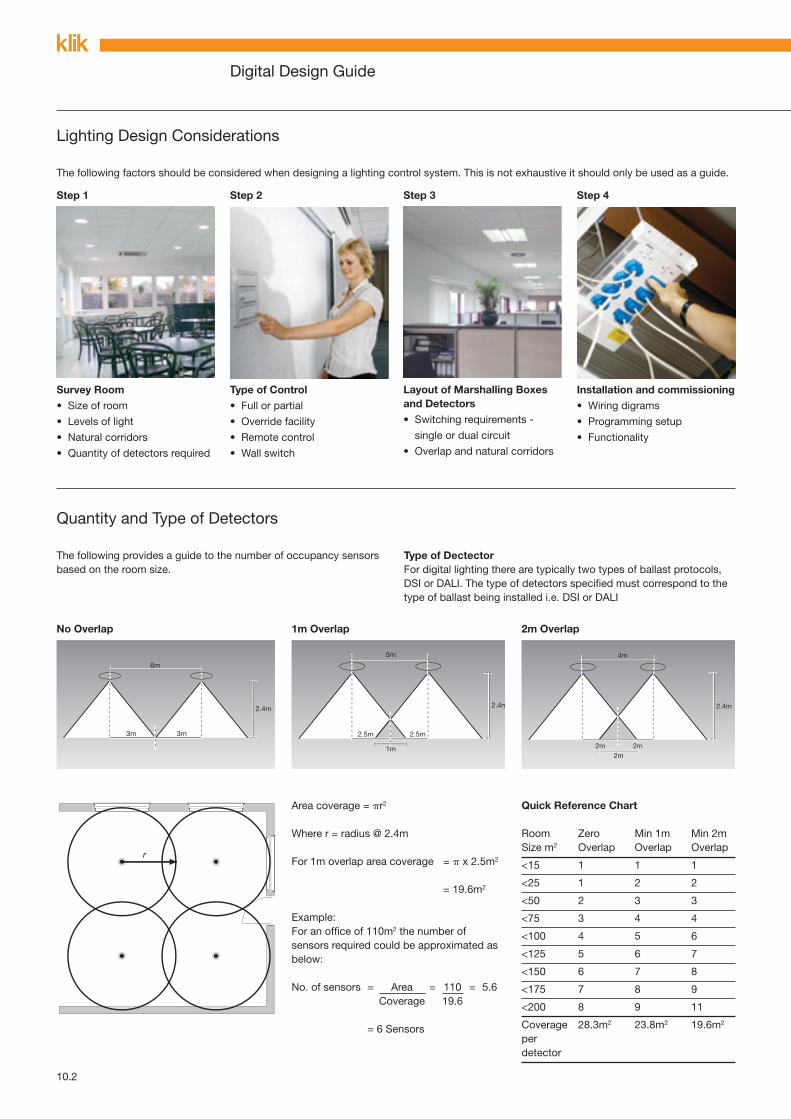
The following factors should be considered when designing a lighting control system. This is not exhaustive it should only be used as a guide.
Step 1 Step 2 Step 3 Step 4
Lighting Design Considerations
The following provides a guide to the number of occupancy sensors based on the room size.
Type of DectectorFor digital lighting there are typically two types of ballast protocols, DSI or DALI. The type of detectors specified must correspond to the type of ballast being installed i.e. DSI or DALI
Quantity and Type of Detectors
No Overlap 1m Overlap 2m Overlap
Area coverage = r2
Where r = radius @ 2.4m
For 1m overlap area coverage = x 2.5m2
= 19.6m2
Example:For an office of 110m2 the number of sensors required could be approximated as below: No. of sensors = Area = 110 = 5.6 Coverage 19.6
= 6 Sensors
Quick Reference Chart
Room Zero Min 1m Min 2mSize m2 Overlap Overlap Overlap
<15 1 1 1
<25 1 2 2
<50 2 3 3
<75 3 4 4
<100 4 5 6
<125 5 6 7
<150 6 7 8
<175 7 8 9
<200 8 9 11
Coverage 28.3m2 23.8m2 19.6m2
perdetector
Survey Room• Size of room
• Levels of light
• Natural corridors
• Quantity of detectors required
Type of Control• Full or partial
• Override facility
• Remote control
• Wall switch
Layout of Marshalling Boxes and Detectors• Switching requirements -
single or dual circuit
• Overlap and natural corridors
Installation and commissioning• Wiring digrams
• Programming setup
• Functionality
10.3
Klik
D
igita
l
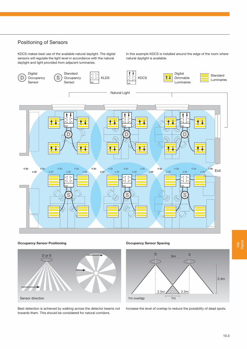
Positioning of Sensors
KDCS makes best use of the available natural daylight. The digital sensors will regulate the light level in accordance with the natural daylight and light provided from adjacent luminaries.
In this example KDCS is installed around the edge of the room where natural daylight is available.
DigitalOccupancySensor
StandardOccupancySensor
KLDS KDCSDigitalDimmableLuminaires
StandardLuminaires
Occupancy Sensor Positioning Occupancy Sensor Spacing
Sensor direction 1m overlap
Best detection is achieved by walking across the detector beams not towards them. This should be considered for natural corridors.
Increase the level of overlap to reduce the possibility of dead spots.

10.4
Comparison Chart
KDCS can be used when an installation uses digital dimmable luminaires throughout. It can also be used in conjunction with KLDS if digital dimming is not required throughout the installation. This has the benefit of reducing the capital costs without compromising the performance.
The following provides a comparison between Klik LDS and Klik DCS part number references:
Klik LDS Klik DCS
Marshalling boxes KLDS4 KDCS4
KLDS6 KDCS6
KLDS8 KDSC8
KLDS10 KDCS10
KLDS12
Pre-wired plugs P22/1.0LSF/2 P55/2
P22/1.0LSF/3 P55/3
P22/1.0LSF/4 P55/4
P22/1.0LSF/5 P55/5
P64AXR/1.0LSF/2 P55AXR/2
P64AXR/1.0LSF/3 P55AXR/3
P64AXR/1.0LSF/4 P55AXR/4
P64AXR/1.0LSF/5 P55AXR/5
Occupancy sensor OS2/P OS3/D (for DSI ballasts)
OS2/PSM OS4/D (for DALI ballasts)
OS3/DS (for DSI ballasts)
OS4/DS (for DALI ballasts)
OS3/DSW (for DSI ballasts)
OS3/DSW (for DALI ballasts)
Controller OSRCA OSDP
OSRCB OSDC or OSDCS

10.6 Hager Catalogue 2007 • Klik Digital
Klik Digital Connection System - KDCS
Description Dimensions Packqty. Cat Ref.
4 outlet distribution box 73mm x 222mm x 238mm 1 KDCS4
6 outlet distribution box 73mm x 222mm x 288mm 1 KDCS6
8 outlet distribution box 73mm x 222mm x 338mm 1 KDCS8
10 outlet distribution box 73mm x 222mm x 388mm 1 KDCS10
Pre-Wired Plugs
Description Packqty. Cat Ref.
Pre-wired plugs with low smoke zero halogen flexible cordDigital plug with 1 metre 10 P55/11.0 mm2 LS0H flexible cord
Digital plug with 2 metre 10 P55/21.0 mm2 LS0H flexible cord
Digital plug with 3 metre 5 P55/31.0 mm2 LS0H flexible cord
Digital plug with 4 metre 5 P55/41.0 mm2 LS0H flexible cord
Digital plug with 5 metre 5 P55/51.0 mm2 LS0H flexible cord
KDCS4
KDCS6
KDCS10
P55/1
10.7
Klik
D
igita
l
Hager Catalogue 2007 • Klik Digital
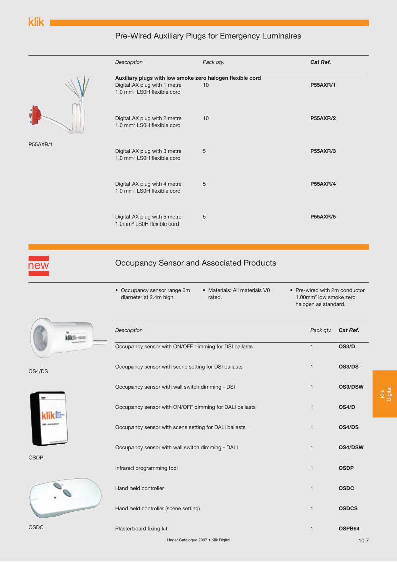
Pre-Wired Auxiliary Plugs for Emergency Luminaires
Description Packqty. Cat Ref.
Auxiliary plugs with low smoke zero halogen flexible cordDigital AX plug with 1 metre 10 P55AXR/11.0 mm2 LS0H flexible cord
Digital AX plug with 2 metre 10 P55AXR/21.0 mm2 LS0H flexible cord
Digital AX plug with 3 metre 5 P55AXR/31.0 mm2 LS0H flexible cord
Digital AX plug with 4 metre 5 P55AXR/41.0 mm2 LS0H flexible cord
Digital AX plug with 5 metre 5 P55AXR/51.0mm2 LS0H flexible cord
Occupancy Sensor and Associated Products
Description Packqty. Cat Ref.
Occupancy sensor with ON/OFF dimming for DSI ballasts 1 OS3/D
Occupancy sensor with scene setting for DSI ballasts 1 OS3/DS
Occupancy sensor with wall switch dimming - DSI 1 OS3/DSW
Occupancy sensor with ON/OFF dimming for DALI ballasts 1 OS4/D
Occupancy sensor with scene setting for DALI ballasts 1 OS4/DS
Occupancy sensor with wall switch dimming - DALI 1 OS4/DSW
Infrared programming tool 1 OSDP
Hand held controller 1 OSDC
Hand held controller (scene setting) 1 OSDCS
Plasterboard fixing kit 1 OSPB64
P55AXR/1
OS4/DS
OSDP
OSDC
• Occupancy sensor range 6m diameter at 2.4m high.
• Materials: All materials V0 rated.
• Pre-wired with 2m conductor 1.00mm2 low smoke zero halogen as standard.
Hager Catalogue 2007 • Technical10.8
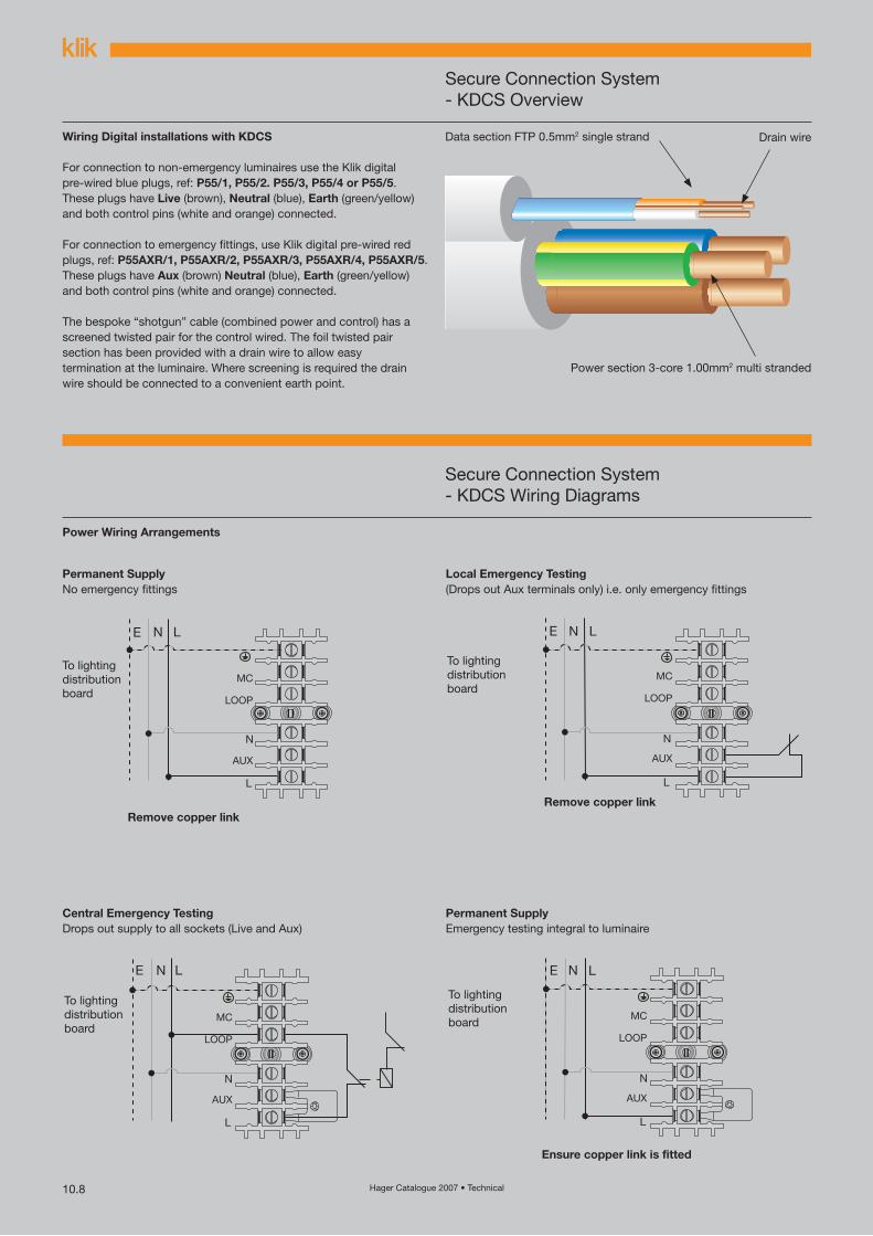
Secure Connection System- KDCS Overview
Wiring Digital installations with KDCS
For connection to non-emergency luminaires use the Klik digital pre-wired blue plugs, ref: P55/1, P55/2. P55/3, P55/4 or P55/5. These plugs have Live (brown), Neutral (blue), Earth (green/yellow) and both control pins (white and orange) connected.
For connection to emergency fittings, use Klik digital pre-wired red plugs, ref: P55AXR/1, P55AXR/2, P55AXR/3, P55AXR/4, P55AXR/5. These plugs have Aux (brown) Neutral (blue), Earth (green/yellow) and both control pins (white and orange) connected.
The bespoke “shotgun” cable (combined power and control) has a screened twisted pair for the control wired. The foil twisted pair section has been provided with a drain wire to allow easy termination at the luminaire. Where screening is required the drain wire should be connected to a convenient earth point.
Data section FTP 0.5mm2 single strand Drain wire
Power section 3-core 1.00mm2 multi stranded
Secure Connection System- KDCS Wiring Diagrams
Power Wiring Arrangements
Permanent SupplyNo emergency fittings
Local Emergency Testing(Drops out Aux terminals only) i.e. only emergency fittings
Central Emergency TestingDrops out supply to all sockets (Live and Aux)
Permanent SupplyEmergency testing integral to luminaire

Hager Catalogue 2007 • Technical 10.9
Klik
D
igita
l
Secure Connection System- KDCS Wiring Diagrams
Control Wiring Arrangements
OS3/D & OS4/D Klik Digital Sensors Control Wiring
In single circuit configuration“Sensor+” and “Sensor-” can be used to connect a Klik digital sensor into the control wiring.
OS3/D, OS4/D and OS3/DS, OS4/DS Klik Digital Sensors Power Wiring
In Split Circuit ModeYou can connect two Klik digital sensors, one to CCTA and a second one to CCTB.
Single Circuit ConfigurationThe connections DA+ and DA- of CCT A are common with DA+ and DA- of CCT B respectively. Therefore all socket outlets receive the same control signal.
Dual circuit configurationIn split circuit mode, control circuits CCT A and CCT B are seperate and can receive different control singals if required.

Hager Catalogue 2007 • Technical10.10
OSDP Digital Programmer
Instructions for use
Changing Pre-set parameters1. Set dill switches to ON or OFF according to desired settings.2. Hold the programmer vertically beneath the occupancy sensor and press button A. The detector turns its load OFF to indicate the beginning of a programming event and turns back on almost immediately if the operation is a success. If the detector output does not turn back on, repeat the operation.
Setting the regulating light level1. Point this unit at the occupancy sensor and adjust the light output using the UP/DOWN buttons until the desired light level is achieved locally. Note: that it may not be possible to do this in the presence of strong natural light.
2. Press STORE, two seconds later the load (regulating ballasts) blinks to indicate a successful store operation. The occupancy sensor will now regulate the light output in order to maintain the level of illuminance at this new set point.
Alloftheseparameterswillbepreservedintheeventofpower lossandcanbere-programmedanynumberoftimes.
Parameter options for OS3/D, OS3/DS, OS4/D, OS4/DS, OS3/DSW and OS4/DSW
1 2 3 4 5 6 7 8 9 10 11 12{
{Options at end off delayFade to off = Yes 5 min 10 min 20 min
Fade to off = No
Off delay add together to give required time
(All off = 10 sec walk test)
Minimum on-time = 20 min
Minimum on-time
= off delay
Bright-out = Yes
StartFull
Power UpOn
Bright-out = No
StartLow
Power UpOff
Occupancy sensor
automatic operation
Occupancy sensor semi -automatic operation
On
Off
Off Off Off Lights turn off
On Off Off Lights stay at minimum output until next occupancy
Off On On Lights regulate below 25% for 3 hours then turn off
Off On Off Lights regulate below 25% until next occupancy
On Off On Lights stay at minimum output for 3 hours then turn off
Optimum settings to perform 10 second walk test
Switches Status
1-9 Off
10-12 On

Hager Catalogue 2007 • Technical 10.11
Klik
D
igita
l
OSDP Digital Programmer
CommissioningThe factory default setting will be appropriate for most applications. However, the installer does have the facility to reprogramme a wide range of parameters and to set the regulating light level using OSDP Digital Programmer.
The following table shows the pre-set factory settings and a brief explanation of each parameter. These parameters may be re-programmed any number of times and all settings will be retained in the event of a power loss.
Hand Held Remote Controller
OSDC and OSDCS infrared remote dimming controller for occupancy sensor
Operation instructionsPoint the handset at the occupancy sensor and press a button. The beam angle is quite narrow, so accurate aiming is important. (Optimum distance 1m - 2.5m, LED indicates battery life)
Key assignment OSDC and OSDCS- Short press to turn off, long press to dim.+ Short press to turn on, long press to brighten.
Product compatibilityPlease note that only those products designed for dimming, and connected to appropriate equipment, can effect dimming with this controller.
Key assignment OSDCS- Short press to turn off, long press to dim.+ Short press to turn on, long press to brighten.6 scene recall buttons (only applicable for OS3/DS, OS4/DS, OS3/ DSW, OS4/DSW).To store, set the lighting level requirements using - or +, then press and hold the scene button until the luminaires blink.
Technical dataDimensions: 120 x 56 x 22mmWeight: 115gBattery type: Alkaline AAA x 2Typical battery life: 1 yearOperating range: 2.5m
OSDC OSDCS
Programming information
Parameter Options Pre-set Application
Power-Up On/Off On Sets the luminaire state at power up irrespective of occupancy. Useful in reducing start-up load following power cut. Power-Up off-responds to occupancy after 30 seconds.
Start-up level Max/Min Max Sets the level at which lamps strike when turning on.
Responses Auto/Semi Auto Auto If set to auto, the occupancy sensor switches the luminaires on and off automatically. If set to semi-auto, the luminaire will not turn on automatically when a person enters the area. It can be turned on using the OSDC or OSDCS hand-held controller by toggling the power switch. When the area is vacated, the light will turn off automatically.
Bright-out Yes/No No If set to yes, movement fails to refresh the off delay if the ambient light level is 100% higher than its desired level, and the luminaire will switch off when the off delay has elapsed.
Minimum on time Yes/No No If set to yes, the luminaire is guaranteed to stay on for at least 20 minutes, regardless of the off delay setting. This effectively overrides the off delay setting.
Off-delay 5-35 minutes 20 minutes The time for which the luminaire will stay on following the last detected movement. Also 10 second setting for walk-testing.
Fade to off Yes/No No When no presence is detected, and after the off delay period, the lamps can fade out instead of switching off (approx 80 seconds to fade from 100% to 0%).
Light level 1-100% 100% Can be set to regulate at any level achievable within the light output range of the fitting.
When vacant Low/Off/Reg <25% Off These are the options for a vacant area after it has timed out. Luminaires can turn off, remain at minimum output, or regulate with a 25% output limit, until the next period of occupancy. If programmed to remain at minimum or regulate below 25%, there is a programmable option to switch off after 3 hours.

Hager Catalogue 2007 • Technical10.12
KDCS - Simplicity and Innovation
1. 2.
A range of mounting options exist for the KDCS. The KDCS can be mounted on a flat surface, vertically or horizontally on drop rods, or beneath trunking or ladder trays.
Large cabling compartment makes wiring easy under site conditions.
3. 4.
Klik digital pre-wired plug are easily connected to the luminaire. Luminaires are connected to the marshalling box using the click in locking action.
5. 6.
Parameters are selected using the handheld programmer (ODSP). Occupancy sensor is programmed with the desired settings using the OSDP.