klondyke storage proposal construction methodology report
TRANSCRIPT
Klondyke Storage Proposal
Construction Methodology Report
Prepared for HOBEC and behalf of the Rangitata Diversion Race Management Ltd
July 2016
Final
RDR Klondyke Storage Proposal Construction Methodology Report
Status: Final July 2016 Project No.: 80502770 i Klondyke Construction Methodology Report - Final.docx
This document has been prepared for the benefit of Rangitata Diversion Race Management Ltd. No liability is accepted by this company or any employee or sub-consultant of this company with respect to its use by any other person.
This disclaimer shall apply notwithstanding that the report may be made available to other persons for an application for permission or approval to fulfil a legal requirement.
QUALITY STATEMENT
PROJECT MANAGER PROJECT TECHNICAL LEAD
Brian Hall Steven Woods
PREPARED BY
………………………………............... ……/……/…… Bryan Peters
CHECKED BY
………………………………............... ……/……/…… Steven Woods
REVIEWED BY
………………………………............... ……/……/…… Peter Foster
APPROVED FOR ISSUE BY
………………………………............... ……/……/…… Brian Hall
CHRISTCHURCH Hazeldean Business Park, 6 Hazeldean Road, Addington, Christchurch 8024 PO Box 13-249, Armagh, Christchurch 8141 TEL +64 3 366 7449, FAX +64 3 366 7780
REVISION SCHEDULE
Rev No
Date Description Signature or Typed Name (documentation on file).
Prepared by Checked by Reviewed by Approved by
0 08/15 Draft for Comment BP SW BH BH
1 10/15 Draft for Comment BP SW BH BH
2 11/15 Draft for Consultation BP SW BH BH
3 11/15 Draft for Consultation BP SW BH BH
4 08/07/2016 Final NF SM
RDR Klondyke Storage Proposal Construction Methodology Report
Status: Final July 2016 Project No.: 80502770 ii Klondyke Construction Methodology Report - Final.docx
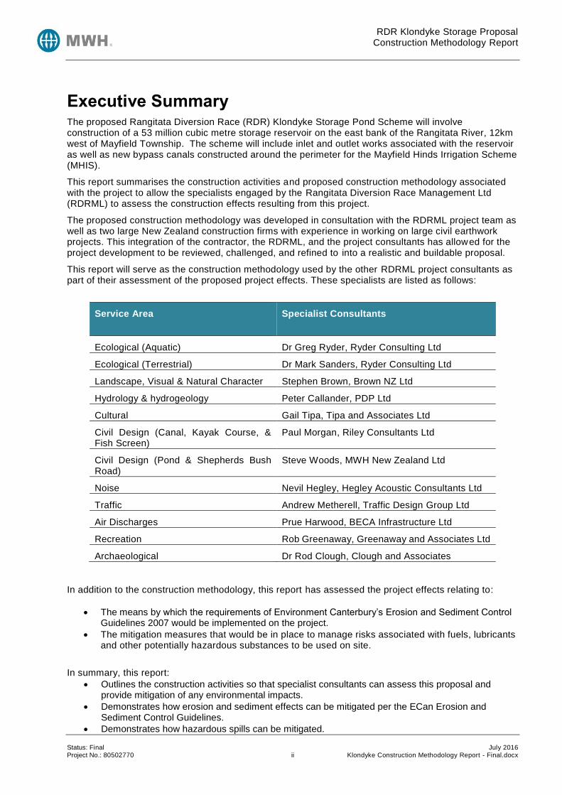
Executive Summary The proposed Rangitata Diversion Race (RDR) Klondyke Storage Pond Scheme will involve construction of a 53 million cubic metre storage reservoir on the east bank of the Rangitata River, 12km west of Mayfield Township. The scheme will include inlet and outlet works associated with the reservoir as well as new bypass canals constructed around the perimeter for the Mayfield Hinds Irrigation Scheme (MHIS).
This report summarises the construction activities and proposed construction methodology associated with the project to allow the specialists engaged by the Rangitata Diversion Race Management Ltd (RDRML) to assess the construction effects resulting from this project.
The proposed construction methodology was developed in consultation with the RDRML project team as well as two large New Zealand construction firms with experience in working on large civil earthwork projects. This integration of the contractor, the RDRML, and the project consultants has allowed for the project development to be reviewed, challenged, and refined to into a realistic and buildable proposal.
This report will serve as the construction methodology used by the other RDRML project consultants as part of their assessment of the proposed project effects. These specialists are listed as follows:
Service Area
Specialist Consultants
Ecological (Aquatic) Dr Greg Ryder, Ryder Consulting Ltd
Ecological (Terrestrial) Dr Mark Sanders, Ryder Consulting Ltd
Landscape, Visual & Natural Character Stephen Brown, Brown NZ Ltd
Hydrology & hydrogeology Peter Callander, PDP Ltd
Cultural Gail Tipa, Tipa and Associates Ltd
Civil Design (Canal, Kayak Course, & Fish Screen)
Paul Morgan, Riley Consultants Ltd
Civil Design (Pond & Shepherds Bush Road)
Steve Woods, MWH New Zealand Ltd
Noise Nevil Hegley, Hegley Acoustic Consultants Ltd
Traffic Andrew Metherell, Traffic Design Group Ltd
Air Discharges Prue Harwood, BECA Infrastructure Ltd
Recreation Rob Greenaway, Greenaway and Associates Ltd
Archaeological Dr Rod Clough, Clough and Associates
In addition to the construction methodology, this report has assessed the project effects relating to:
The means by which the requirements of Environment Canterbury’s Erosion and Sediment Control Guidelines 2007 would be implemented on the project.
The mitigation measures that would be in place to manage risks associated with fuels, lubricants and other potentially hazardous substances to be used on site.
In summary, this report:
Outlines the construction activities so that specialist consultants can assess this proposal and provide mitigation of any environmental impacts.
Demonstrates how erosion and sediment effects can be mitigated per the ECan Erosion and Sediment Control Guidelines.
Demonstrates how hazardous spills can be mitigated.

RDR Klondyke Storage Proposal Construction Methodology Report
Status: Final July 2016 Project No.: 80502770 iii Klondyke Construction Methodology Report - Final.docx
Outlines the management and monitoring requirements envisioned to confirm that the mitigation measures proposed are implemented during construction are effective.

RDR Klondyke Storage Proposal Construction Methodology Report
Status: Final July 2016 Project No.: 80502770 iv Klondyke Construction Methodology Report - Final.docx
Rangitata Diversion Race Management Ltd
Klondyke Storage Proposal
Construction Methodology Report
CONTENTS
Executive Summary .................................................................................................................................. ii
1 Introduction ......................................................................................................................................... 1
2 Construction Activities ........................................................................................................................ 2
2.1 General .......................................................................................................................................... 2
2.2 Initial Works ................................................................................................................................... 2
2.3 Depots & Fuel Storage .................................................................................................................. 3
2.4 Stripping of Vegetation and Soils .................................................................................................. 3
2.5 Earthworks Construction ................................................................................................................ 4
2.6 Reservoir Lining ............................................................................................................................. 4
2.7 Concrete Works ............................................................................................................................. 5
2.7.1 General ................................................................................................................................... 5
2.7.2 Inlet Structures ........................................................................................................................ 5
2.7.3 Outlet structures ..................................................................................................................... 6
2.8 Race & Drainage ........................................................................................................................... 6
2.8.1 General ................................................................................................................................... 6
2.8.2 MHIS Diversion ....................................................................................................................... 6
2.8.3 RDR Race Modification ........................................................................................................... 7
2.8.4 Gully Race .............................................................................................................................. 7
2.9 Dewatering..................................................................................................................................... 7
2.10 Access Roads & Construction Traffic ............................................................................................ 8
2.11 Kayak Course ................................................................................................................................ 9
2.12 Construction Programme ............................................................................................................... 9
2.13 Construction Plant ....................................................................................................................... 10
2.14 Construction Quantities ............................................................................................................... 11
3 Erosion and sediment Control .......................................................................................................... 13
3.1 General ........................................................................................................................................ 13
3.2 Construction Sequence ............................................................................................................... 13
3.3 Control of run-on water ................................................................................................................ 14
3.4 Separation of Clean and Dirty Water ........................................................................................... 14
3.5 Protection of the Land Surface from Erosion ............................................................................... 16
3.6 Prevention of Sediment from Leaving the Site ............................................................................ 17
3.7 Special Considerations ................................................................................................................ 18
3.7.1 Gully Race & Drop Structure ................................................................................................. 18
RDR Klondyke Storage Proposal Construction Methodology Report
Status: Final July 2016 Project No.: 80502770 v Klondyke Construction Methodology Report - Final.docx
3.7.2 River Outlet Channel............................................................................................................. 19
3.7.3 Concrete Batching ................................................................................................................ 20
4 Management of Hazardous Spills ..................................................................................................... 21
5 Construction Management Plan ....................................................................................................... 22
6 Monitoring ......................................................................................................................................... 23
6.1 General ........................................................................................................................................ 23
6.2 Establishment .............................................................................................................................. 23
6.3 Construction Period ..................................................................................................................... 23
6.4 Decommissioning Period ............................................................................................................. 24
6.5 Post Construction Phase ............................................................................................................. 24
7 Summary & Conclusion .................................................................................................................... 25
8 References ....................................................................................................................................... 26
LIST OF TABLES
Table 2-1: Site Works Plant Schedule ................................................................................................... 11
Table 2-2: Construciton Quantity Summary ........................................................................................... 12
Table 3-1: Soak Pit and Sediment Retention Pond Sizing ..................................................................... 16
Table 8-1: Secialist Reference Authors ................................................................................................. 26
LIST OF FIGURES
Figure 1-1: Scheme Layout ........................................................................................................................ 1
Figure 2-1: Access Points .......................................................................................................................... 9
Figure 2-2: Programme Gantt Chart ........................................................................................................ 10
APPENDICES
Appendix A Drawings

RDR Klondyke Storage Proposal Construction Methodology Report
Status: Final July 2016 Project No.: 80502770 Page 1 Klondyke Construction Methodology Report - Final.docx
1 Introduction The proposed Rangitata Diversion Race (RDR) Klondyke Pond (‘the Pond’) will involve the construction of a 53 million cubic metre storage reservoir on the east bank of the Rangitata River, 12km west of Mayfield Township. The Pond will include inlet and outlet works associated with the reservoir as well as new bypass canals constructed around the perimeter for the Mayfield Hinds Irr igation Scheme (MHIS). The general layout is shown on the figure below
This report describes the construction activities and outlines how potential environmental effects from these earthworks and other construction activities will be mitigated. Specifica lly it addresses:
Construction methodology
Erosion and sediment control
Management of hazardous spills (fuel, lubricants, etc.)
Other construction effects will arise and will be dealt with by other specialist reports, specifically those addressing dust, noise, vibration and traffic.
It is noted that the measures outlined in this report are not the only way in which to manage these issues and different contractors may have alternative management strategies. The measures outlined in this report are considered a baseline for compliance with the resource consent and would form the basis of the construction management plan that the RDRML is to prepare prior to construction commencing .
Appendix A Drawing sheet C023 shows the scheme option under consideration.
Figure 1-1: Scheme Layout
Montalto Power Station
MHIS Offtake RDR
RDR Klondyke Storage Proposal Study Area
RDR Intake and Sand Trap

RDR Klondyke Storage Proposal Construction Methodology Report
Status: Final July 2016 Project No.: 80502770 Page 2 Klondyke Construction Methodology Report - Final.docx
2 Construction Activities
2.1 General
The proposed construction methodology was developed in consultation with the RDRML project team as well as two large New Zealand construction firms with experience with on large civil earthwork projects. This integration of the contractor, the RDRML, and the project consultants has allowed for the project development to be reviewed, challenged, and refined to into a realistic and buildable proposal.
This section provides some detail of how the pond will be constructed, including:
A general description of the construction activities that will be undertaken, including the erosion and sediment control measures to be used.
A general construction programme.
The types of materials that will be used and from where they will be sourced.
The types of machinery that will be utilised.
The storage and use of potentially hazardous substances.
Some of the mitigation measures that will be implemented. Construction activities for the project will occur principally within the footprint area defined by the storage reservoir and the embankments around the reservoir perimeter. In addition there will be areas external to the footprint used for spoil disposal, depots and other temporary works. The extent of the reservoir concepts is shown on drawing C023 in Appendix A. The location and extent of all major activities associated with the construction of the pond is shown on drawing C050 in Appendix A. A reliable water supply will be required for several primary site functions, including concrete batching, vehicle/plant cleaning and dust suppression. A nominal allowance of 0.5 cumecs has been discussed with RDRL to cover these needs. This water may be extracted as required or kept in a separate storage to insure it availability when extraction from the race is restricted. A proposed water storage/ water supply is shown on drawing C050 in the northeast corner of the site, however, it may also be located on top of the adjacent terrace to the east (within Depot #1) if a pressurised filling point is preferred. A typical pond would be in the order of 100x70 m in plan dimension, with a depth of 2m, containing a total volume of 14,000 cubic meters of water. The following subsections describe the specific activities to be undertaken. For clarity these sections should be read in conjunction with reference to the drawings contained in Appendix A.
2.2 Initial Works
The project will include initial works, or pre-construction activities, associated with investigating the project site, formation of access roads, construction of temporary site bu ildings and laydown areas, mechanical workshops, ecology projects, and storage of hazardous materials such as fuel. Specific initial works will include:
Ecology works, including establishment of a proposed ecological refuge adjacent to the Rangitata River close to the river discharge channel. Refer to Drawing C050 in Appendix A and the Draft Ecological Refuge Concept Plan in Appendix C of Ryder Consulting (June 2016). This would be constructed by moving the stone piles out of the pond site onto the refuge site to re-create 1 ha of rocky habitat interspersed with native plantings. The wetlands will be created by clearing existing old river channels and widening and deepening these to expose groundwater. Sealing of Montalto Road from Shepherds Bush Road through to the north bank of the RDR to minimise dust that would otherwise be created during the establishment and use of Depot #1.
Implementing sediment management measures to control runoff from areas of disturbed ground. Sediment trap basins will also be formed before runoff exits the site back to natural drainage channels. Refer Section 3.
RDR Klondyke Storage Proposal Construction Methodology Report
Status: Final July 2016 Project No.: 80502770 Page 3 Klondyke Construction Methodology Report - Final.docx
2.3 Depots & Fuel Storage
There are two primary depot sites (#1 & #2) and one temporary depot site (#3) shown on drawing C050. Each of the two primary depot sites will contain some or all of the following items with estimated area required for each:
Site offices for 100 staff 20,000 m2
Staff parking 10,000 m2
Plant and workshop 20,000 m2
Material storage 10,000 m2
Concrete batching plant 15,000 m2 (with capacity of producing 70 m3 of concrete per hour)
Depot #3 will be primarily for overnight plant storage and for some materials, and will only be in use while the in-river works are in progress. It will be located on the grassy flats near the base of the terrace and not within the active gravel river bed. Given the depot’s close proximity to open water and underground seepage there will be no fuel storage allowed and spill kits will be kept on-board all major plant and refuelling trucks. The depot is likely to be located within the flood channel for significant rainfall events. All plant and water sensitive materials will be removed from the depot whenever significant weather events are forecast. Other limitations placed on depot #3 are:
No concrete batching will be carried out
Refuelling will be carried out within a bunded/sealed area with capacity for 1.5 times the refuelling trucks total contents volume
A diesel generator may be used (with a suitable spill kit)
The timeframe for “temporary” is denoted as not more than 1 year The concrete batching plant and material storage areas may be positioned within the depot to maximise the clear distance to the nearest houses to minimise any noise issues. Depots and their associated plant are expected to receive their power supply from the local electricity network, so diesel generators should not be required. There will be a need to have diesel generators nearby the construction for large concrete structures (spillways, gate structures, etc.) to provide local electrical needs. Any diesel generator used on site will carry self -contained spill kits and refuelling will be done by mobile fuel trucks. Fuel supply is proposed to come from a single central location at the north end of the site adjacent to the spoil area. The fuel storage and dispenser will come as a kit-set style arrangement from the selected fuel supplier, and will include the tank, an impermeable membrane and the perimeter bunding sufficient to contain a significant fuel spill. The perimeter site access road will extend from Shepherds Bush Road (refer section 2.10) up to the fuel storage area, providing access for refuelling tankers coming to and from the site, and for site based vehicles to access the refuelling point.
2.4 Stripping of Vegetation and Soils
Initial stripping will require the removal of large shrubs and trees. Anything of salvageable commercial value will be sold and removed from site. Burning will take place as close as practicable to the area where the trees are felled, but will not take place within 100m of a public road or 50m from the site boundary (refer to the Smoke Management Plan BECA (2016)). In order to prepare the site for earthworks, the surface materials will be removed by clearing and grubbing to approve areas for stockpiling or disposal off the site. Topsoil and organic material will then be stripped to a depth of the order of 150 mm to 250 mm and stockpiled for reuse on the embankment external batters or for revegetation of spoil disposal areas.
RDR Klondyke Storage Proposal Construction Methodology Report
Status: Final July 2016 Project No.: 80502770 Page 4 Klondyke Construction Methodology Report - Final.docx
Other surface materials that are unsuitable or excess to requirements for embankment construction will be removed for stockpiling in designated areas. There are two soil disposal sites, one to the north and one to the south. These soil disposal sites have been sized to receive around 1M cubic meters of material requiring an average lift of 1.0 to 1.5 m. The finished spoil perimeter will be merged into surrounding ground levels with batters not exceeding 1V:5H to allow for traversing by stock and farm vehicles. Natural runoff from the disposal area will be captured in grassed swales and discharged to ground via soak pits. The location and alignment of swales and soak pits will change constantly as works progress across the site. The location of both primary spoil disposal areas are shown on C050 and C058 in Appendix A. Drawing C058 provides an indication of where material is being removed (cut) and where it is being placed as either compacted fill or spoil. Both spoil disposal areas will be returned to pasture on completion of the project.
2.5 Earthworks Construction
Earthworks construction involves the preparation of the ground surface around the perimeter of the storage area to receive the embankment fill. The borrow areas within the reservoir foot print will require conditioning of the fill to ensure it is suitable to be picked up and transported for placement in controlled lifts prior to compaction. Conditioning of fill may include screening for particular sizing, screening for organic material, and modification of water content. Some earthworks are also required for the proposal ecological refuge adjacent to the Rangitata River close to the river discharge channel. The wetlands will be created by clearing existing old river channels and widening and deepening these to expose groundwater.
The active earthworks will typically be confined to a north-south strip of approximately 25% of the total pond footprint. Material will typically be excavated from the north end of the strip and taken to form the outer embankments, the largest of which is at the south end. The active earthworks strip will move west to east as work progresses to minimise adverse effects related to open excavation. Drawing C058 in Appendix A provides a schematic of the cut to fill and cut to spoil process, and how this relates to the layout of the site.
Anticipated plant will include dozers, water carts, a fleet of scrapers, graders and compaction plant such as vibrating rollers.
Once the earthworks are substantially complete the batters will be trimmed to final grade to allow placement of the lining within the pond and topsoiling and grassing of the external batters. Depending on the contractor’s ability to lay liner on the completed formation, delays due to weather (or other factors) may result in the active exposed footprint having to increase up to 50% of the total pond footprint.
Any exposed or unvegetated surface that could be subject to erosion by wind will be kept wet via the use of water carts and movable sprinklers and/or flooding of completed sections of liner. Water will be sourced from the RDR canal and maybe stored in a pond to ensure it can be readily accessed. The contractors have also indicated that an elevated pond may be useful to increase the speed of cart refilling. Per drawing C050, this pond would be located at the base of the RDR MHIL offtake noted as water storage/water supply. From discussions with contractors, this pond would likely be 150 m wide x 150 m long x 2m deep and lined with local natural materials.
Dust suppression is covered in more detail by the Klondyke Pond Dust Management Plan.
Natural runoff from the pond footprint will be captured in swales and discharged to ground via soak pits. The location of these swales and soak pits will change constantly as works progress across the site, but in general will drain to localised low points in order to prevent excess water from entering the active work areas. Plan C050 shows the principal pond/soak pits.
2.6 Reservoir Lining
The batter and pond floor surfaces will be progressively prepared for installation of the lining material. The preferred liner will be a synthetic man-made material (HDPE or a similar alternative).
RDR Klondyke Storage Proposal Construction Methodology Report
Status: Final July 2016 Project No.: 80502770 Page 5 Klondyke Construction Methodology Report - Final.docx
A synthetic liner material would be transported to site via the road network. The rolls will be rolled out across the surface to be lined, such that it can be seam welded (or lapped) to adjacent lining material to form a surface free of any substantial leaks. It may also be stockpiled in the depot to provide ready access to the material as it is needed. The liner once laid will be partially covered by rock rip-rap. The rock rip-rap would be transported to site via the road network from a quarry most likely located in Timaru. Natural runoff from the pond footprint will also be captured in swales and discharged into the areas of newly completed liner construction. This will help to protect the new liner from wind. Any excess runoff within the lined area will be channelled to temporary ponding outside of the main footprint and either discharged to ground via soak pit or treated by settling pond to remove contaminants before being discharged to the irrigation race.
2.7 Concrete Works
2.7.1 General
Appurtenant structures such as emergency spillways, chutes, gate structures and stilling basins will be constructed from reinforced concrete. Concrete would be transported from local certified batching plants and transported to site via the road network, depending on the quantity and quality required. Concrete may also be batched on site which would require set-up of a batching plant area within one of the depot sites shown on C050. This batching site would include stockpiles of the basic concrete components (sand, cement, aggregate) and also would require a water supply to be provided from the RDR canal. Concrete component material would be source from off site and transported to site via the road network. Additional construction materials, including reinforcing steel, structural steel, formwork and falsework, will be brought to site by large commercial vehicles as it is required for incorporation into the works. Some construction material will be stored on site for use later in the programme but will typically be kept in a locked fenced enclosure within one of the depot areas. For the drop-structure in the river bed the concrete colour will be darkened with either an integral admixture or a surface coating to achieve a mid-grey colour and reduce the visual impact of a man-made structure within a natural environment. Other structures may also be coloured if they are considered to be in a visually sensitive area.
2.7.2 Inlet Structures
The primary inlet structures are:
New control gate and bypass weir to regulate flow down the main race
New control gate to regulate flow into the storage pond
New spillway and stilling basin to dissipate excess energy from flow into the storage pond
Construction of both of the new control gates and bypass weir will require diversion of the main race and dewatering of the foundations (referred to in following sections). The new spillway and stilling basin will require completion of the adjacent section of pond excavat ion and embankment. Concrete for each structure will be placed starting with foundation works or ground slabs, and followed by external walls and spanning elements. Reinforcement for each element will be generally be placed immediately before concrete is poured. Fresh concrete will be covered to prevent early water loss and assist the curing process. Work on connecting elements can typically be continued once concrete has reached its design strength or a minimum safe strength to carry short term loads. The layout of the inlet structures is shown on C030 in Appendix A.
RDR Klondyke Storage Proposal Construction Methodology Report
Status: Final July 2016 Project No.: 80502770 Page 6 Klondyke Construction Methodology Report - Final.docx
2.7.3 Outlet structures
The primary outlet structures are:
New weir, spillway and stilling basin to dissipate excess energy from flow out of the storage pond
New sluice outlet and control gate structure
New MHIS outlet and control gate structure
New spillway and stilling basin to dissipate excess energy from flow out of the gully and into the riverbed
Construction of both outlet structures and the stilling basins will require dewatering of the foundations (referred to in following sections). The new spillway and adjacent stilling basin will require completion of the adjacent section of pond embankment. Concrete for each structure will be placed starting with foundation works or ground slabs, and followed by external walls and spanning elements. Reinforcement for each element will be generally placed immediately before concrete is poured. Fresh concrete will be covered to prevent early water loss and assist the curing process. Work on connecting elements can typically be continued once concrete has reached its design strength or a minimum safe strength to carry short term loads. The layout of the outlet structures is shown on C031 in Appendix A. Construction of the outlet structures will occur in stages as follows:
Initial site works and foundations will occur at early stages of the project before the embankment fill is placed.
Construction of the inlet and outlet components will occur at later stages, particularly the inlet components to coordinate with the liner placement.
Construction of the spillway will occur after completion of the embankment.
Construction of the outlet channel to the river can occur at any stage in the construction as it is independent of the embankment/storage construction.
The proposed ecological refuge will be constructed early in the project during site establishment and prior to major construction works.
2.8 Race & Drainage
2.8.1 General
The proposed works will include the formation of new sections of race as well as smaller drainage channels. This will include:
The MHIS diversion race (permanent but de-established- 100m of the race to be removed at the end of construction)
RDR race modification to suit new control structures (permanent)
New race connecting RDR to the storage pond (permanent)
Perimeter run-on collection channels (permanent)
Perimeter run-off collection channels (permanent)
Gully race connecting outlet works to the river (permanent)
Stock water race running along the top of the eastern terrace (permanent). The new stock water race will be constructed whilst the existing stock water race is still operating. The existing stock water race will not be disconnected until the new system is constructed so that the supply of stock water is not interrupted by construction.
Construction of these waterways will require excavation, cut to waste, cut to fill, compaction of insitu and imported lining material, placement of rock protection, top-soiling and revegetation.
2.8.2 MHIS Diversion
The MHIS race that currently runs through the pond footprint will need to be rerouted to the perimeter of the footprint. This will likely run along the western perimeter. The diversion will be routed over or under the gully race and will connect back into the existing MHIS race downstream of the site. Drawing C050 in Appendix A shows both options for the MHIS diversion.

RDR Klondyke Storage Proposal Construction Methodology Report
Status: Final July 2016 Project No.: 80502770 Page 7 Klondyke Construction Methodology Report - Final.docx
2.8.3 RDR Race Modification
The RDR race will require modification to suit the new intake works. The affected area is shown shaded yellow on drawing C050 in Appendix A.
This modification will require the following:
Coffering (i.e. temporarily blocking) of the RDR race upstream and downstream of the diversion and inlet structures.
Formation of a temporary RDR diversion on the true left to bypass the coffered section of race works and allow irrigation operation to continue unimpeded.
Raising of the embankment heights upstream of the intake works to address higher water levels that will result from the higher proposed flows from the river intake. This is detailed in the RDR Canal Modification Construction Methodology Report (Riley Consultants).
Removal of the coffer dams and refilling/reinstatement of the temporary bypass on completion of the intake and diversion works.
Temporary water supply for site works that may include a pond, a tank, and a pressurised bowser
Temporary shut downs to the RDR Canal to allow the coffer dam works to be installed and uninstalled.
Other modification works will also be required to direct water from the RDR race and into the storage pond and also to divert minor irrigation flows along the eastern perimeter of the pond footprint. Works within the RDR race are likely to cause increases in suspended sediment going down the race. The work method proposed is to construct a temporary channel diversion which is consistent with the Environment Canterbury’s Erosion and Sediment Control Gu ideline (2007). These guidelines recommend diverting flow away from the work site as the preferred solution to minimise erosion and sediment generation in running water.
2.8.4 Gully Race
The outlet works from the storage pond feed into the downstream gully to return excess and scour water back to the river. The gully will be modified to carry these flows and the works will include , as shown on drawing C203:
Formation and armouring of a suitable channel down the gully
Construction of a drop structure connecting the end of the gully into the river bed
Formation of a return channel within the river bed
Works within the gully and river bed will require temporary storage of plant within a small depot. This depot will be located above normal river flows and plant will be removed if any significant flow event is forecast. Refuelling of plant will be carried out by a mobile tanker that will return to the main construction site and depots when not in use. Public access to and along the river bed will be maintained.
2.9 Dewatering
The proposed works require several new flow control structures to be constructed in and adjacent to groundwater sources (the RDR race and the Rangitata River) . Groundwater will therefore need to be extracted in order to lower the water tables and allow for construction at depth.
To allow for continued use of the RDR during construction a section of race will need to be dewatered. This may include the following:
Construction of coffer dams (likely to be required in the RDR canal for inlet works and Mayfield Hinds canal for outlet works)
Driving of sheet piling
Installing of well points
Pumping of ground water into adjacent treatment ponds Construction of the drop structure in the river bed will require similar dewatering measures.

RDR Klondyke Storage Proposal Construction Methodology Report
Status: Final July 2016 Project No.: 80502770 Page 8 Klondyke Construction Methodology Report - Final.docx
The quantity of water extracted is unknown as it will depend on the final design detail of each structure, the groundwater level at the time and the contractors methodology. However, given the size and depth of structures being considered we believe the dewatering flow will be in the order of 500 l/s (within an assumed area approximately 30 x 30 m). This flow estimate is based on:
Permeability 5 x 10⁻⁴ m/s
Flow area 5m2 / m perimeter
Draw down of 3m in the excavation
Hydraulic grade of 2x3 m / 10 m
Excavation perimeter 120 m
Factor of safety 2.5 All extracted water will be treated in a settling pond to remove unwanted contaminants before being discharged into a watercourse (i.e. the irrigation canal) or, in the case of the gully drop structure, discharged to ground (e.g. the Rangitata river bed).
2.10 Access Roads & Construction Traffic
Access roads are required to accommodate construction traffic through the course of the construction, providing access from adjacent public roads onto and around the site. Construction and maintenance of these roads will require the following:
Stripping of topsoil and loess
Placement and compaction of a gravel road formation
Water spraying, as required, to minimise dust nuisance A formal construction access road will be formed around the perimeter of the site along the north, west and southern sides, while access within the site footprint will vary to suit the phase and location of works at the time. Construction traffic onto and around the site will include scrapers, dump trucks, compaction plant, excavators, dozers, cranes, concrete trucks and transporters (refer section 2.13 for specific plant list). Most traffic will be contained on site but external traffic using the public road network will be required for:
Concrete and related materials
Raw concrete components for on-site batching
Rock protection (rip-rap)
Light vehicles to transport the work force to and from the site
Special material (bedding)
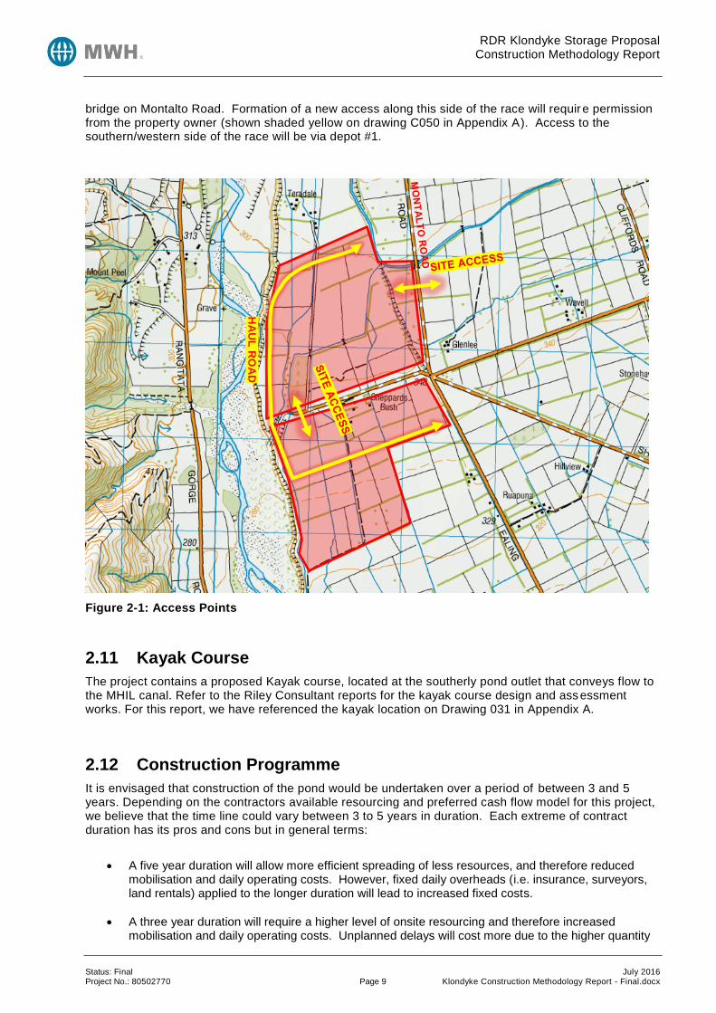
Seepage liner Access points into the site are likely to be established off both Montalto Rd and Shepherds Bush Rd, providing entry into both ends of the construction site. From these access points a network of internal roads will be formed to provide entry to the main work areas – storage pond site, disposal site, perimeter access and inlet/outlet works. The likely location of these access points is shown below, although these may vary depending on contractor preferences. Montalto Road is a regularly used through route used by both the public and the contractors vehicles. If it is subject to significant traffic movements it will reformed with suitably designed subgrade layers to suit the traffic loading, reformed to provide adequate drainage and chip-sealed. Shepherds Bush Rd is used as recreational access to the river bed by the public and will also be in regular use by the contractor. The road will be relocated south, outside of the proposed pond footprint. The proposed Shepherds Bush road has been designed to align with the proposed outer haul road shown on Figure 2-1. Refer to Appendix A where the Shepherds Bush road conceptual design has been provided on drawings C205 and C206. The RDR intake will need to be accessed from both sides of the RDR race. Vehicles and plant accessing the northern/eastern side of the race will access the site from the north side of the existing
RDR Klondyke Storage Proposal Construction Methodology Report
Status: Final July 2016 Project No.: 80502770 Page 9 Klondyke Construction Methodology Report - Final.docx
bridge on Montalto Road. Formation of a new access along this side of the race will require permission from the property owner (shown shaded yellow on drawing C050 in Appendix A). Access to the southern/western side of the race will be via depot #1.
Figure 2-1: Access Points
2.11 Kayak Course
The project contains a proposed Kayak course, located at the southerly pond outlet that conveys flow to the MHIL canal. Refer to the Riley Consultant reports for the kayak course design and ass essment works. For this report, we have referenced the kayak location on Drawing 031 in Appendix A.
2.12 Construction Programme
It is envisaged that construction of the pond would be undertaken over a period of between 3 and 5 years. Depending on the contractors available resourcing and preferred cash flow model for this project, we believe that the time line could vary between 3 to 5 years in duration. Each extreme of contract duration has its pros and cons but in general terms:
A five year duration will allow more efficient spreading of less resources, and therefore reduced mobilisation and daily operating costs. However, fixed daily overheads (i.e. insurance, surveyors, land rentals) applied to the longer duration will lead to increased fixed costs.
A three year duration will require a higher level of onsite resourcing and therefore increased mobilisation and daily operating costs. Unplanned delays will cost more due to the higher quantity
HA
UL
RO
AD
RDR Klondyke Storage Proposal Construction Methodology Report
Status: Final July 2016 Project No.: 80502770 Page 10 Klondyke Construction Methodology Report - Final.docx
of resources on stand-by. However, fixed daily overheads applied to the shorter duration will lead to reduced fixed costs.
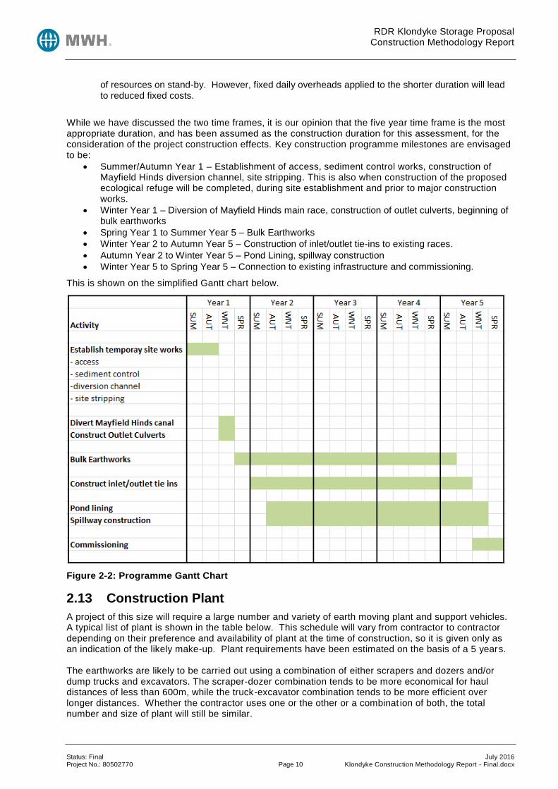
While we have discussed the two time frames, it is our opinion that the five year time frame is the most appropriate duration, and has been assumed as the construction duration for this assessment, for the consideration of the project construction effects. Key construction programme milestones are envisaged to be:
Summer/Autumn Year 1 – Establishment of access, sediment control works, construction of Mayfield Hinds diversion channel, site stripping. This is also when construction of the proposed ecological refuge will be completed, during site establishment and prior to major construction works.
Winter Year 1 – Diversion of Mayfield Hinds main race, construction of outlet culverts, beginning of bulk earthworks
Spring Year 1 to Summer Year 5 – Bulk Earthworks
Winter Year 2 to Autumn Year 5 – Construction of inlet/outlet tie-ins to existing races.
Autumn Year 2 to Winter Year 5 – Pond Lining, spillway construction
Winter Year 5 to Spring Year 5 – Connection to existing infrastructure and commissioning.
This is shown on the simplified Gantt chart below.
Figure 2-2: Programme Gantt Chart
2.13 Construction Plant
A project of this size will require a large number and variety of earth moving plant and support vehicles. A typical list of plant is shown in the table below. This schedule will vary from contractor to contractor depending on their preference and availability of plant at the time of construction, so it is given only as an indication of the likely make-up. Plant requirements have been estimated on the basis of a 5 years. The earthworks are likely to be carried out using a combination of either scrapers and dozers and/or dump trucks and excavators. The scraper-dozer combination tends to be more economical for haul distances of less than 600m, while the truck-excavator combination tends to be more efficient over longer distances. Whether the contractor uses one or the other or a combinat ion of both, the total number and size of plant will still be similar.

RDR Klondyke Storage Proposal Construction Methodology Report
Status: Final July 2016 Project No.: 80502770 Page 11 Klondyke Construction Methodology Report - Final.docx
Table 2-1: Site Works Plant Schedule
Plant Type Number on Site
35t Scrapers (typ CAT 637)
and/or
35t Dump Trucks (typ CAT 769c)
Combined total of 21
Dozers (typ D6)
and/or
Excavator (typ CAT 336e)
Combined total of 6
Graders (typ CAT 14) 6
Water Cart (typ CAT 725) 6
Vibrating Roller Compactor (12 t) 6
Combined Total Plant Number 45
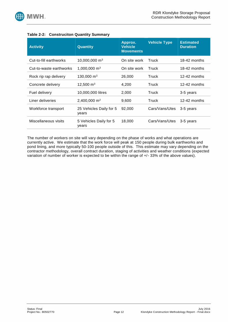
2.14 Construction Quantities
The following table summarises the major quantities of materials required for construction. It also identifies the order of the number of vehicle movements that will be required to transport these materials to the site via the public road network. Each vehicle movement is equal to one pass of the vehicle. For example a concrete truck dropping off a batch of concrete will make 2 trips, one to the site fully laden, and then one from the site empty. Other assumptions are as follows:
Concrete trucks carry 6m3 per delivery
Rip rap and specialised fill are delivered by a truck and trailer combination, each carrying 10 m 3
(approximately 20 tonne) of material
RDR Klondyke Storage Proposal Construction Methodology Report
Status: Final July 2016 Project No.: 80502770 Page 12 Klondyke Construction Methodology Report - Final.docx
Table 2-2: Construciton Quantity Summary
Activity Quantity Approx. Vehicle Movements
Vehicle Type Estimated Duration
Cut-to-fill earthworks 10,000,000 m3 On site work Truck 18-42 months
Cut-to-waste earthworks 1,000,000 m3 On site work Truck 18-42 months
Rock rip rap delivery 130,000 m3 26,000 Truck 12-42 months
Concrete delivery 12,500 m3 4,200 Truck 12-42 months
Fuel delivery 10,000,000 litres 2,000 Truck 3-5 years
Liner deliveries 2,400,000 m2 9,600 Truck 12-42 months
Workforce transport 25 Vehicles Daily for 5 years
92,000 Cars/Vans/Utes 3-5 years
Miscellaneous visits 5 Vehicles Daily for 5 years
18,000 Cars/Vans/Utes 3-5 years
The number of workers on site will vary depending on the phase of works and what operations are currently active. We estimate that the work force will peak at 150 people during bulk earthworks and pond lining, and more typically 50-100 people outside of this. This estimate may vary depending on the contractor methodology, overall contract duration, staging of activities and weather conditions (expected variation of number of worker is expected to be within the range of +/- 33% of the above values).
RDR Klondyke Storage Proposal Construction Methodology Report
Status: Final July 2016 Project No.: 80502770 Page 13 Klondyke Construction Methodology Report - Final.docx
3 Erosion and sediment Control
3.1 General
Construction of the scheme will involve significant cut to fill earthworks, combined with clearance and stockpiling of material and re-vegetation of cut and fill slopes. Approximately 11 million cubic metres of cut to fill earthworks is required to form the reservoir and embankments. Approximately 500Ha of ground would be disturbed during the construction process. The Rangitata River is located immediately to the west of the proposed construction site. Erosion and sediment control measures are needed to prevent the discharge of uncontrolled suspended sediment to the river during the construction process. Guidance on the appropriate control measures is provided by Environment Cante rbury’s Erosion and Sediment Control Guideline 2007 (ESCG). This document provides guidance to contractors and developers on how to manage earthworks operations, in the soil conditions experienced in Canterbury, to mitigate the generation and transportation of sediment. The key principles of this document are:
To control run-on water
To separate clean from dirty water
To protect the land surface from erosion
To prevent sediment from leaving the site Under the ESCG, sites are classified depending of soil types and topography. Based on ESCG Table 5.1 the site would be classified as “Canterbury Plains and other flat lands with good infiltration and low water table”. The site is favourable from a sediment and erosion control perspective, given that is underlain by several metres of free draining gravel and, apart from the terrace faces, slopes are gentle (less than 1 in 50). The only permanently running water-courses crossing the site are man-made races that will be diverted as required to accommodate the various construction phases. Existing drainage is characterised by discharge over the existing terrace face and down the natural gully, as is evident by the erosion patterns. This erosion control assessment is supported by the following drawings provided in the Appendix:
Typical Site Layout for Construction (Dwg C050): Depicts location of typical erosion and sediment control measures and other construction facilities i.e. depots, refuelling points, water storage ponds, ecological refuge, relocation of Shepherd Bush Road.
Runoff Plan (Existing) (Dwg C055): Depicts the existing drainage catchment runoff patterns including both natural and man-made features associated with drainage collection.
Runoff Plan (Construction) (Dwg C056): Depicts the construction phase drainage catchment run-off patterns including swales, clean water run-off, typical incremental 25% floor stripping, dirty water run-off and treatment.
Runoff Plan (Post Construction) (Dwg C057): Depicts the post construction phase drainage catchment run-off patterns including the location of swales and channels that will become permanent post construction features for the long term management of catchment runoff.
Cut to Fill/Spoil Schematic (Dwg C058): Depicts the location of cut and fill areas, general trends for material transport, typical incremental 25% floor stripping and haul road associated with phased earthwork activity.
3.2 Construction Sequence
The scheme concept is illustrated on drawings C023 and C050, provided in Appendix A. It is preferred that earthworks for pond should be a self-contained operation, i.e. a cut to fill balance would be achieved without hauling material from borrow sources outside the reservoir footprint (with the exception of small quantities of specialised material). For this pond there will be in the order of 1M m3 of excess spoil (typically topsoil and organic matter) that cannot be reused in the pond construction.
RDR Klondyke Storage Proposal Construction Methodology Report
Status: Final July 2016 Project No.: 80502770 Page 14 Klondyke Construction Methodology Report - Final.docx
This waste material will be placed in two spoil sites, located at existing level ground, one to the north and one to the south of the storage pond. Spoil sites will be formed on pastoral land by first removing existing topsoil, placing the waste material to depths of 1-1.5 m, replacing the topsoil and re-establishing grass cover to return the land to pastoral farmland. The final landforms established would be integrated into the surrounding topography (following the advice from a landscape architect) and would maintain existing drainage patterns. At an average depth of 1.3m, approximately 80Ha of spoil sites will need to be developed. The location of these spoil sites are shown on C050 contained in Appendix A. Haul roads will need to be developed to allow movement of the large quantities of earthworks material around the site, generally running north-south to link the two spoil disposal areas. At the end of the project the haul road would be returned to pastoral farmland. A single lane gravel track would be left at the toe of the pond embankment to provide for long term access. The location of the embankments (and permanent perimeter access road) is shown on C050 contained in Appendix A. Following formation of the initial haul roads, the next step will be to remove topsoil and finer grain gravel blends from the pond footprint. Most of topsoil will be placed in spoil disposal areas, with small stockpiles retained for use in the permanent construction of the embankment (e.g. topsoil for slope revegetation). The finer grain natural soils may be stockpiled for later use in conjunction with installation of the new liner.
3.3 Control of run-on water
The first principle of the ESCG is to prevent water from outside the earthworks site from entering the site. This is generally achieved by a series of diversion drains upslope of the construction site and potentially via further diversion drains within the site. The topography of this site is characterised by a grade in the order of 1:140 running parallel with the river valley. Perpendicular to the river, the slope is generally east to west toward the river at a grade in the order of 1:1000. A series of drainage gullies cross the site and these features, although generally dry have the potential to direct concentrated flows of water toward the pond during high rainfall conditions. Therefore to control run-on water, consideration needs to be given to sheet flows from either the north or east that follow the existing drainage pattern. Within the stripped storage pond footprint any runoff flow will generally be able to soak into the gravels exposed in the reservoir floor area. Once embankment construction rises above existing ground, run-on water can be channelled along a drainage swale at the toe of the external batter and then to a settlement pond before exiting into an existing drainage or irrigation channels. Drawing C050 in Appendix A shows how run-on water should, in our opinion, be controlled. In addition to this, drawings C055-057 show the overall site drainage pre-construction, during construction and post construction. The following points should be noted in relation to these drawings:
The RDR provides a cut-off for run-on water coming from the east
The re-routed stock water race along the east side of the storage pond also provides a cut-off for run-on water coming from the east
Run-on water to the west of the storage pond will tend to run along natural depressions that can be seen in the contour lines. Part of this run-on will be collected in the rerouted MHIS canal while the remaining run-on will discharge down the face of the terrace to the river. This is naturally occurring run-off so the adjacent construction works will not change the nature or volume of run-off, or create any adverse effects over and above what presently occurs.
3.4 Separation of Clean and Dirty Water
The ESCG promotes the separation of clean water (that which has run across undisturbed ground) from dirty water (that which has run across disturbed ground). This section of the report discusses the means by which clean water will be separated from the earthworks construction zone. Water which falls wi thin the construction zone needs to be collected and treated before being discharged. The ESCG (section 7.2.1) recommends the use of sediment detention structures to remove suspended sediment before water is discharged. Furthermore, in areas of high infiltration and low water table, soakage pits are endorsed (section 7.2.4) as an effective means of detaining sediment and disposing of water. Specific
RDR Klondyke Storage Proposal Construction Methodology Report
Status: Final July 2016 Project No.: 80502770 Page 15 Klondyke Construction Methodology Report - Final.docx
guidance is given in the ESCG (table 7.7) to allow sizing of the sediment detention ponds or soakage pits based on catchment area. Soakage pits of the recommended sizes would be progressively constructed as stripping of topsoil and finer grain soils begins. It is noted that, as these surface layers are removed, large quantities of permeable unsaturated gravel would be exposed and, in effect, the floor of the excavation and fill surfaces will become a large soakage pit. At that stage the only water requiring further treatment will be that which lands on the external side slopes of embankment fills, water which lands directly on haul roads or soil disposal areas, and water that lands on the newly constructed liner. Run-off from the external embankment will be treated by a grassed buffer strip and allowed to run -off into natural channels and races. Runoff from roads and disposal areas will be diverted by topsoil bunds that border the construction site and discharged to ground via soakage pits. Runoff from the new liner will be discharged to a separate soakage pit outside of the pond footprint. If this soakage pit does not have sufficient capacity it can be converted to a sediment treatment pond (as defined by ESCG), where sediment is removed from suspension and treated water is then discharged to the MHIS. It is considered that disposal of water via soakage pits gives a high degree of protection to the Rangitata River from construction related sediment discharges. As water ponds in a soakage pit suspended sediment will drop out of suspension and be deposited at the bottom of the pit. Further removal of suspended sediment will occur by filtration as water passes through unsaturated gravel and is returned to groundwater. The exact removal of suspended sediment is difficult to quantify, however , grading curves from samples of sandy gravel collected from the site indicate that it should be successful in removing the finest (silt sized) soil particles that would be present in runoff water. This is further endorsed by the positive practical experience of the effectiveness of Canterbury gravels as filters when water is abstracted from groundwater for water supply purposes. The proposed disposal system means that there is no direct discharge of “dirty” water to the Rangitata River. It is only returned indirectly from the groundwater system and settlement pond after primary settling (and secondary filtration for soakage pits) and is expected to be substantially free of suspended sediment after this process. The majority of accumulated sediment can be either left in the soakage pit or settlement pond when it is decommissioned (filled and covered with top soil) or can be removed and disposed of in the spoil disposal area. Drawing C050 (and drawings C055-C057) in Appendix A shows how dirty water may be controlled for the proposed scheme. The following points should be noted in relation to this:
Run-off from the spoil disposal areas are contained by a topsoil bund along the western boundary, collected at the southern end, where it is discharged to ground via a soakage pit.
Run-off from the pond footprint is collected within the pond excavation. A large portion of the water will discharge directly into the exposed gravel where it falls, while some will collect in purpose made soakage pits within the footprint and then discharge to ground.
Run-off from the new liner will be either discharged to an external soakage pit, or discharged to a settlement pond for treatment and then discharged to the MHIS.
Run-off from the outer face of the embankment will generally be treated in the grass verge and then collected in the races running around the perimeter. Along the southern end of the pond this run-off will be collected in the roadside swale.
Any swales or channel used to collect runoff will be hydro-seeded to promote fast grass growth that will help with resisting erosion and removing sediment.
The ESCG provide guidance on sizing of sediment retention ponds. These are sized on the basis on being able to contain a 5 year ARI 10 hour event (section 7.2.1). Soakage pits are discussed under section 7.2.4 and are sized on the same basis as retention ponds. We have carried out a preliminary sizing of retention ponds and soak pits for the main identified construction catchment, based on the following:
5 year 10 hour rainfall event from HIRDS, 55mm over 10 hours
Runoff coefficients from Table 7.6 of ESCG
Pond depth of 1 m
RDR Klondyke Storage Proposal Construction Methodology Report
Status: Final July 2016 Project No.: 80502770 Page 16 Klondyke Construction Methodology Report - Final.docx
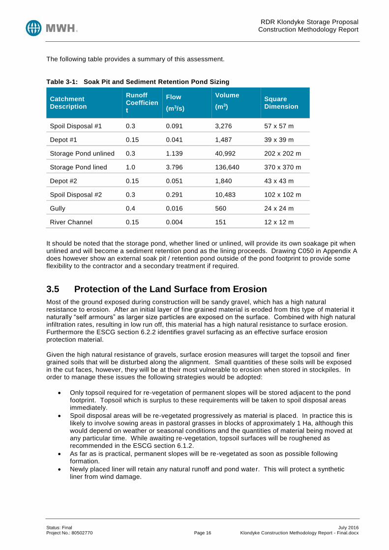
The following table provides a summary of this assessment.
Table 3-1: Soak Pit and Sediment Retention Pond Sizing
Catchment Description
Runoff Coefficient
Flow
(m3/s)
Volume
(m3)
Square Dimension
Spoil Disposal #1 0.3 0.091 3,276 57 x 57 m
Depot #1 0.15 0.041 1,487 39 x 39 m
Storage Pond unlined 0.3 1.139 40,992 202 x 202 m
Storage Pond lined 1.0 3.796 136,640 370 x 370 m
Depot #2 0.15 0.051 1,840 43 x 43 m
Spoil Disposal #2 0.3 0.291 10,483 102 x 102 m
Gully 0.4 0.016 560 24 x 24 m
River Channel 0.15 0.004 151 12 x 12 m
It should be noted that the storage pond, whether lined or unlined, will provide its own soakage pit when unlined and will become a sediment retention pond as the lining proceeds. Drawing C050 in Appendix A does however show an external soak pit / retention pond outside of the pond footprint to provide some flexibility to the contractor and a secondary treatment if required.
3.5 Protection of the Land Surface from Erosion
Most of the ground exposed during construction will be sandy gravel, which has a high natural resistance to erosion. After an initial layer of fine grained material is eroded from this type of material it naturally “self armours” as larger size particles are exposed on the surface. Combined with high natural infiltration rates, resulting in low run off, this material has a high natural resistance to surface erosion. Furthermore the ESCG section 6.2.2 identifies gravel surfacing as an effective surface erosion protection material. Given the high natural resistance of gravels, surface erosion measures will target the topsoil and finer grained soils that will be disturbed along the alignment. Small quantities of these soils will be exposed in the cut faces, however, they will be at their most vulnerable to erosion when stored in stockpiles. In order to manage these issues the following strategies would be adopted:
Only topsoil required for re-vegetation of permanent slopes will be stored adjacent to the pond footprint. Topsoil which is surplus to these requirements will be taken to spoil disposal areas immediately.
Spoil disposal areas will be re-vegetated progressively as material is placed. In practice this is likely to involve sowing areas in pastoral grasses in blocks of approximately 1 Ha, although this would depend on weather or seasonal conditions and the quantities of material being moved at any particular time. While awaiting re-vegetation, topsoil surfaces will be roughened as recommended in the ESCG section 6.1.2.
As far as is practical, permanent slopes will be re-vegetated as soon as possible following formation.
Newly placed liner will retain any natural runoff and pond water. This will protect a synthetic liner from wind damage.

RDR Klondyke Storage Proposal Construction Methodology Report
Status: Final July 2016 Project No.: 80502770 Page 17 Klondyke Construction Methodology Report - Final.docx
Stockpiles and spoil sites will need to be individually managed for sediment control. Specific measures to be implemented are:
Diversion of upslope drainage water by excavated swale.
Surface tracking of the exposed surface to minimise erosion (ESCG 6.2.4).
Disposal of runoff water by vegetative buffer zones (ESCG 7.1.1), sediment fences (ESCG 7.1.3) and/or soakage pits (ESCG 7.2.4) depending on the size of the catchment.
Drawing C050 in Appendix A shows how erosion would, in our opinion, be controlled for the pond. The following points should be noted in relation to this:
Topsoil will generally be stockpiled within the confines of the spoil disposal area.
Minor topsoil stockpiles will also be located along the eastern, western and southern boundaries of the pond to reduce double handle of this material.
Runoff from disturbed areas that are being regrassed will generally be contained for treatment and discharge into adjacent races or soakage pits.
3.6 Prevention of Sediment from Leaving the Site
Measures to prevent sediment from leaving the site due to erosive forces are discussed in the sections above. Consideration must also be given to movement of sediment from the site by vehicles leaving the site. The earthworks operation will essentially be self-contained within the construction site. Haulage trucks or scrapers will generally not use public roads during the project, except for limited quantities of specialist materials (such as rock rip rap) which cannot be supplied from on-site excavations. Movement of vehicles from the construction site onto public roads will consist mostly of concrete trucks, delivery vehicles for reinforcing steel (and other building materials), truck-trailer combinations carrying rip rap and light vehicles to transport the workforce to and from site. Access onto public roads would be restricted to three points, namely:
Onto Montalto Road via site access roads into and out of the adjacent depot site.
Onto Shepherds Bush Road via site access roads into and out of the adjacent depot site.
Onto Shepherds Bush Road via site access roads into and out of the pond footprint. In order to mitigate the transfer of sediment onto the public road system, the following measures will be implemented:
Haul roads traversed by on road vehicles will be surfaced in gravel to form an “all weather” surface that will minimise the sediment that can be picked up by vehicles.
Shaker ramps (cattle stop or similar) will be utilised at the formal exit points as outlined in section 7.1.4 of the ESCG to remove sediment before vehicles leave the site.
Sweeping of intersection points with public roads from time to time as required to keep them to a standard acceptable to the district council. This would typically be at fortnightly intervals but will vary as required depending on how much dirt/debris is being tracked from the site (this is likely to change as work transitions to different activities and weather conditions alternate from wet to dry).

RDR Klondyke Storage Proposal Construction Methodology Report
Status: Final July 2016 Project No.: 80502770 Page 18 Klondyke Construction Methodology Report - Final.docx
3.7 Special Considerations
3.7.1 Gully Race & Drop Structure
The gully race allows either spillway flow or sluicing flow to return back into the natural water course. Spillway flows would typically be released during high intensity rainfall events, while sluicing flows will be released periodically to extract sediment from the storage pond and return it to the river. The race is steep so will require rock armouring to ensure it remains stable during high flows. The gully race will be approximately 350 m long.
A drop structure is required at the downstream end of the gully to dissipate excess energy from the steep drop into the natural river bed. The drop structure will be similar to that used on the pond spillway, constructed using precast and insitu concrete elements to form a robust structure to contain high velocity water and promote dissipation of excess energy.
Construction of this race will need to be specifically managed for sediment control. Given the close proximity to the Rangitata River, and the potential for contaminants to enter the watercourse, this is a very sensitive part of the site and will require clear guidelines and methodology to mitigate potential construction effects.
Appendix A contains drawing C050 showing specific measures that will be implemented during construction of the gully race and drop structure. These measures include:
Topsoil bunding on the uphill slope of excavations to prevent clean run-off mixing with dirty run-on water.
Containment of dirty run-on water within the excavated canal and pond/soak pit
Treatment of dirty run-on water to remove contaminant and discharged to ground Other measures that are not specifically shown but will also be implemented are:
Minimising of open excavation to that required for the current work process (typically no more than 25% of the total area but up to 50% if climatic condition prevent final lining, topsoil placement or revegetation)
Revegetation of disturbed areas as soon as it is practical after work has been completed (typically within one month except over the winter season when revegetation would be put on hold until spring)
Containment and treatment of run-on/run-off from construction access roads
Use of silt fencing or hay-bails to provide improved sediment containment and removal The soak pit at the downstream end of the gully is approximately 3.5 m above the adjacent Rangitata River channel invert. Preliminary hydraulic assessment of the Rangitata River has indicated that a 3.5 m water depth will equate to a flow of around 870 m3/s. From Regional Flood Estimation this flow has a return period of less than a year (the mean annual flood is 1400 m 3/s). Assuming that a 0.01 m depth of sediment were washed out of the stripped gully over the period of one day this would equate to 500 tonnes of additional sediment. According to flow to suspended sediment relationship (graph from Ryder et al), a flow of 870 m3/s will carry in excess of 2000 mg/l, equating to 150,000 tonne of natural sediment in one day. The additional sediment contributed by the soak pit will therefore have minimal effect on river clarity. Section 6 refers to construction monitoring and the removal of this accumulated material at the completion of the river channel construction. Appendix A also contains drawing C203 showing typical sections through the gully and the river. This drawing shows the likely location and sizing of the gully race, the adjacent access road and the drop structure.

RDR Klondyke Storage Proposal Construction Methodology Report
Status: Final July 2016 Project No.: 80502770 Page 19 Klondyke Construction Methodology Report - Final.docx
3.7.2 River Outlet Channel
Following the gully race and drop structure, a wider river channel will be constructed to allow flow to go directly into the nearest active river braid. Construction of this outlet channel will be regarded as in-river works and specific sediment control measures put in place. In order to separate the excava tion from the river, a plug of gravel (or cofferdam) would be left between the river and the open excavation. This will prevent inflow to the excavation from flowing directly into the adjacent river channel. The river channel will be approximately 450 m long. In the event of a significant flood occurring during construction, the cofferdam would be overwhelmed and would need to be reinstated once the flood recedes. While it is possible that sediment will be released to the river in such an event, it will be during conditions when natural suspended sediment levels in the river are high and the impact on the river will be negligible.
Appendix A contains drawing C050 showing the alignment of the river channel. Sediment control measures will include:
Gravel bunding (coffer dam) of the downstream end of active excavation
Gravel bunding (coffer dams) of any other natural braids/channels that may flow through the active excavation
Containment of dirty run-on water within the excavated canal and soak pit
Treatment of dirty run-on water to remove contaminant and discharged to ground Other measures that will also be implemented are:
Minimising of open excavation to that required for the current work process (typically no more than 25% of the total area but up to 50% if climatic condition prevent final lining, topsoil placement or revegetation)
Revegetation of disturbed areas as soon as it is practical after work has been completed (typically within one month except over the winter season when revegetation would be put on hold until spring)
Containment and treatment of run-on/run-off from construction access roads
Use of silt fencing or hay-bails to provide improved sediment containment and removal if runoff requires pre-treatment immediately upstream of a containment pond/soak pit
An ecological refuge is proposed adjacent to the Rangitata River close to the river discharge channel. Refer to Drawing C050 in Appendix A and the Draft Ecological Refuge Concept Plan in Appendix C of Ryder Consulting (June 2016). The wetlands associated with the ecological refuge will be created by clearing existing old river channels and widening and deepening these to expose groundwater. The wetland habitat will be separated from the spillway river discharge channel, with the open shrubland and lizard habitat forming a buffer between them. Therefore construction of the proposed ecological refuge can be completed independently of the outlet channel to the river. In the event of a significant flood occurring during construction (or operation), then it’s likely the wetlands will require some sediment removal. This is likely to be completed by an excavator to reinstate the wetland are to a suitable useable function. The soak pit at the downstream end of the river outlet channel is approximately 2-3 m above the adjacent Rangitata River channel invert. Preliminary hydraulic assessment of the Rangitata has indicated that a 2.5 m water depth will equate to a flow of around 340 m3/s. From Regional Flood Estimation this flow has a return period of less than a year (the mean annual flood is 1400 m3/s). Sediment deposited within this pond will therefore be washed down the river in relatively small flood events occurring several times each year. Assuming that a 0.1 m depth of sediment were washed out of the stripped river cut over the period of one day this would equate to 3,600 tonne of additional sediment. According to flow to suspended sediment relationship (graph from Ryder et al), a flow of 340 m3/s will carry 1350 mg/l, equating to 40,000 tonne of natural sediment in one day. The additional sediment contributed by the soak pit will therefore have minimal effect on river clarity. Section 6 refers to construction monitoring and the removal of this accumulated material at the completion of the river channel construction.
Appendix A also contains drawing C203 showing typical sections through the gully and the river. This drawing shows the likely location and sizing of the river outlet channel.
RDR Klondyke Storage Proposal Construction Methodology Report
Status: Final July 2016 Project No.: 80502770 Page 20 Klondyke Construction Methodology Report - Final.docx
Once in service the river channel will be subject to natural riverbed modification during flood events, causing general bedload movement and reshaping the natural meander. The outlet river channel is therefore likely to require periodic reinstatement to ensure that it continues to function properly. As a result the channel may need to be longer or shorter in order to tie in with the nearest natural river braid.
3.7.3 Concrete Batching
Due to the close proximity of certified batching plants in Ashburton it is possible that the contractor for this work would choose to source their concrete needs from off site. Concrete would be delivered as required and ready mixed in concrete trucks.
There is also the possibility that the selected contractor may merit in on-site batching. This would still require a similar number of trucks as all the raw materials would still need to be brought to site. On site the material would need a separate stockpiling area, plus dry storage for cement plus the batching area. The batching process could have adverse construction effects relating to:
Rainfall run-off from stockpiles
Noise from operation of batching plant
Dust emissions from stockpiles and mixing processes
If the contractor chooses to pursue site batching this will involve a number of new site activities with associated construction effects. Specifically:
Vehicle movements to and from site transporting base component material
Water take required for mixing and washing of batching plant
Site processing of wash water and discharge treated water
Stockpiling of material on site
Noise effects from the batching plant The effects from the above activities are typical of other similar activities on the site , and will therefore be managed and minimised in a similar manner. Specific measures will include:
Traffic management of vehicle entering and leaving site (refer to Klondyke Storage Proposal: Transportation Assessment Report, Andrew Metherell, Traffic Design Group Ltd)
Available water take agreed with RDR
Wetting of material likely to cause dust nuisance (refer to Klondyke Pond Dust Management Plan, Prue Harwood, BECA)
Containment and processing of contaminated runoff. Similar measures of capturing runoff into settling ponds would be utilised for site runoff. If during trials the water chemistry was not suitable (PH >8.5) for discharge, then chemical additives (such as carbon dioxide) would be used.
Regular maintenance of the batching plant to minimise noise levels (refer to Klondyke Pond Noise Management Plan, Nevil Hegley, Hegley Acoustic Consultants Ltd)
Disposal of waste off site at an approved refuse area, (e.g. containers used to store concrete additives or excess materials such as cement that cannot be incorporated into the project works or are unable to be reused on other project sites)

RDR Klondyke Storage Proposal Construction Methodology Report
Status: Final July 2016 Project No.: 80502770 Page 21 Klondyke Construction Methodology Report - Final.docx
4 Management of Hazardous Spills Fuel and lubricants will need to be stored on site for the earthmoving fleet. Fuel will be s tored in an on-site tank within the designated depot areas. The tanks used for fuel storage will have a secondary containment system, either in the form of a double skin or a containment bund around the tank site. It is envisaged that one centralised refuelling area will be developed on the site as shown on C050. Depot storage sites with secondary containment will also be used for lubricants and any other similar hazardous substances. Re-fuelling of earthmoving equipment will generally be done directly from the centralised storage tank. Plant working in the river bed will be refuelled by mobile mini-tanker and carried out within a sealed bunded area. Spills at both mobile and central re-fuelling sites will be managed by spill kits. Spill kits would be located at the contractor’s depot, any temporary facilities and the main fuel storage area. The type of spill kit on site would be GP100 supplied from New Zealand Safety or an approved equivalent. Contents of GP100 spill kit are as follows:
10 x GP pads
5 x 10L GP particulate
2 GP 2.5m socks
3 GP 45 x 45cm pillows
Goggles, Gloves, Respirator, Disposable apron, Disposal bag, Brush & pan The location of spill kits will be made known to all personnel on site by means of initial inductions to site/toolbox meetings. The following measures would be utilised to mitigate against spill risks:
Employees and sub-contractors will be trained in both refuelling and maintenance operations and the spill management procedure.
In the event of a spill, the Foreman/ Construction Engineer will notify the Project Environmental Engineer, who will first inform the RDRML, and then ECAN and the Engineer of the remedial measures being implemented.
Refuelling shall be carried out by an appropriately trained operator who will ensure that the tanker auto switch-off is fully operational and a spill containment kit is available.
No refuelling or maintenance activities will be carried out within 20m of a watercourse .
All minor maintenance (including oil changes) not carried out off site will occur within designated bunded areas and on impervious ground. Those that occur on site will have supplementary spill kits and waste collection systems.
Covered waste bins will be provided at the main site office at the entrance to the site and at the various satellite smoko / portacom offices throughout the site for collection of waste drums, oily rags, absorbent material, oil filters, grease cartridges etc. Oily rags and used absorbents will be bagged before being put into waste bins, and then disposed of off-site in approved dump sites.
All spills will be contained and appropriately cleaned up. A licensed operator will appropriately dispose of contaminated materials off site.
All waste oil will be removed from site.
The above measure will ensure that the risk of a spill and the effects of any spill are minimal and acceptable.
RDR Klondyke Storage Proposal Construction Methodology Report
Status: Final July 2016 Project No.: 80502770 Page 22 Klondyke Construction Methodology Report - Final.docx
5 Construction Management Plan The contractor will prepare a detailed Construction Management Plan (CMP). This plan describes how the contractor will manage the day to day work activities, taking into account all the relevant aspects and conditions of building the proposed project. On site issues will typically include:
Site health and safety
Site security
Public health and safety
Operating hours
Noise and vibration control
Air and dust management
Stormwater and sediment control
Waste disposal and material reuse
Traffic management A typical CMP would include the following objectives:
To provide detail of the construction methodologies and management of effects during construction.
To provide guidance on environmental management for the construction of the proposed works and associated facilities.
To describe what actions will be taken to manage and avoid or reduce the risk of adverse environmental effects during construction
To provide a list of key positions and points of contact during construction
To describe how stakeholders will be kept informed during construction and how issues will be managed.
A typical CMP would include the following sections:
Purpose & Scope
Personnel
Team Structure and Contact Details
Responsibilities
Environmental Policy and Objectives
Project Specific Environmental Requirements
Environment Management Sub-plans
Work Method Statements
Training and Induction
Subcontractor Management
Complaint Management
Monitoring
Site Inspections
Non-Conformance and Corrective/Preventative Action
Meetings
System Reviews
Environmental Reviews
Erosion and Sediment Control Plan
Spill Management Plan
Dust Management Plan
Vibration Management Plan
Waste Management Plan
Noise Management Plan
Works in the River Management Plan
Archaeological Management Plan

RDR Klondyke Storage Proposal Construction Methodology Report
Status: Final July 2016 Project No.: 80502770 Page 23 Klondyke Construction Methodology Report - Final.docx
6 Monitoring
6.1 General
The construction process will require the implementation of a monitoring process in order to ensure that critical aspects of the construction are carried out correctly and that conditions of consent are met. This monitoring process will apply both during construction and post construction in order to cover both construction and operation of the scheme. The following sections provide an outline of the monitoring process and detail how it would apply to the various phases of the project.
6.2 Establishment
At the initiation of site works the monitoring will be established. This will require early interaction between the contractor and clients site agent to put the monitoring system in place and run through a pre-start checklist. The follows items would be included in this phase:
Review the Construction Management Plan
Initial site meeting to discuss monitoring
Check that pre-start notifications have been actioned
Check that environment mitigation measures are in place
Check that mitigation measures are in accordance with plans and documentation
6.3 Construction Period
As construction proceeds the monitoring process will require periodic checking, modification and maintenance to ensure that it remains fully compliant and addresses any significant variations in the construction process. The following items would be included in this phase and may be carried out by either the contractor or the client’s specialist site agent:
Weekly review of construction operation to identify significant changes
Maintenance of mitigation measures (i.e. remove sediment from soak pits and ponds, check that soak pit decant is operating effectively)
Check water courses and catch drains for signs of erosion, and reinforce/reinstate as required
Check that areas of completed works have been revegetated or lined (i.e. spoil disposal area, embankment formation, lined areas)
Check that stripped active earthworks area is minimised within practical limits
Check water cart operation and effectiveness at suppressing dust
Carry out dust monitoring as per the BECA dust monitoring plan (Klondyke Pond Dust Management Plan, Prue Harwood, BECA)
Carry out noise monitoring as per the Hegley noise management Plan (Klondyke Pond Noise Management Plan, Nevil Hegley, Hegley Acoustic Consultants Ltd)
Carry out surface water clarity monitoring at all points of discharge to surface water.
Check terrace edge for signs of erosion or instability
Monitor the accumulation of sediment on the public roads, including the project access locations to determine when roads shall be cleaned. Initial site inspections would be undertaken with Council staff to establish an acceptable standard required for compliance.
RDR Klondyke Storage Proposal Construction Methodology Report
Status: Final July 2016 Project No.: 80502770 Page 24 Klondyke Construction Methodology Report - Final.docx
6.4 Decommissioning Period
At the completion of construction the contractor will demobilise from site. This will entail the removal of environmental control measures that apply to active site works, and the implementation of new control measures that apply to the long term operation of the completed works. The fo llowing items would be included in this phase:
Dispose of any leftover excess sediment in soak pits and ponds
Fill, topsoil and revegetate soak pits and ponds
De-establish construction drainage plan (channels and swales)
Establish long term drainage plan (channels and swales)
Check that all disturbed area of construction have been either lined or have vegetation established
Remove refuelling sites, test for contaminants, and remove any contaminated soil to an authorised disposal site location.
De-establish all depot areas, place topsoil and revegetate
Check that completed works are in accordance with construction drawings
Check river channel for hydraulic capacity and safe for fish to pass through
Obtain compliance signoff from ECAN and Ashburton DC
Prepare, review and implement the Operation and Maintenance Manual (O&MM)
6.5 Post Construction Phase
After construction and decommissioning are complete the storage pond will require an ongoing long term maintenance regime to be put in place for the life of the storage pond (nominally 50 years). This will check that the operation of long-term environmental measures is effective and to identify any adverse effects that require specific remedial action to be taken. The following items would be included in this phase with checks typically carried out during periodic dam safety inspections:
Observation of long-term site drainage plan checking for signs of erosion, restriction in capacity, no significant ponding
Check vegetation establishment, revegetate any areas that have lost their coverage
Carry out vegetation control - watering, fertilising, mowing, weed removal
Check the river channel hydraulic capacity and general stability
Check that the river channel is safe for fish passage and bypass
Check terrace edge for signs of long-term erosion or instability
Apply additional long-term stability measures as required
As this structure has a High PIC rating it will be subject to various levels inspections in order to comply with current dam safety regulations. These inspection types are as follows:
Monthly Routine Inspection by RDR staff with specific training on a simplified inspection process (e.g. checking water levels, piezo heights, visual check of embankments, etc.).
Annual Intermediate Dam Safety Review by a specialist consultant familiar with the design and construction looking at a similar check list to the monthly inspection.
Five yearly Comprehensive Dam Safety review by a specialist independent consultant who was not involved in the design or construction of the facility. Generally this is a more detailed and in depth assessment and would include systems check, sighting M&E operations, general operation check, health and safety, testing of water and soil sample, etc.)
RDR Klondyke Storage Proposal Construction Methodology Report
Status: Final July 2016 Project No.: 80502770 Page 25 Klondyke Construction Methodology Report - Final.docx
7 Summary & Conclusion
This report provides details of a construction methodology that we expect will be used for construction of the proposed Klondyke Storage pond with a total volume of 53 million cubic meters. We have itemised the significant construction activities in order to provide an understanding of the nature and scope of the site works. These construction activities include:
Initial works
Depots and fuel storage
Stripping of vegetation and soils
Earthworks construction
Reservoir lining
Concrete works (inlet/outlet structures, stilling basins)
Races & drainage
Dewatering
Access roads and traffic management The construction works are characterised by the following estimates:
A time line of 3 to 5 years for completion of the site works, with 5 years being the most realistic
45 items of major plant in operation during peak site works
Total earthworks quantity of 11M cubic meters
The report provides some details around erosion and sediment control, detailing the proposed mitigation measures that will be put in place, specifically:
How control measure relate to construction sequence
Control of run-on water
Separation of clean and dirty water
Protection of land surfaces from erosion
Prevention of sediment from leaving the site
Associated with the gully race and drop structure
Associated with the river outlet channel
Associated with concrete batching Finally the report provides further detail specific to spill management, contents of the construction management plan, and Monitoring. The Monitoring provides discussion around the likely requirements for site works and breaks this process into four phases – establishment, construction, decommissioning and post construction operation. In conclusion, we believe that the site works as detailed, along with the mitigation measures proposed, will result in minimal, and in our opinion, acceptable adverse effects on the environment.

RDR Klondyke Storage Proposal Construction Methodology Report
Status: Final July 2016 Project No.: 80502770 Page 26 Klondyke Construction Methodology Report - Final.docx
8 References Environment Canterbury, Erosion and Sediment Control Guideline, 2007
In addition to the reference above there are several specialist report referenced in our report, with authors listed in the table below:
Table 8-1: Secialist Reference Authors
Report
Specialist
Klondyke Storage Pond: Engineering Report
Steven Woods, MWH
Klondyke Pond Dust Management Plan Prue Harwood, BECA Infrastructure Ltd
Klondyke Pond Smoke Management Plan Prue Harwood, BECA Infrastructure Ltd
Klondyke Storage Proposal: Water Quality and Aquatic Ecology Assessment
Dr Greg Ryder, Ryder Consulting Ltd
Klondyke Pond Preliminary assessment Stephen Brown, Brown NZ Ltd
Klondyke Pond Noise Management Plan Nevil Hegley, Hegley Acoustic Consultants Ltd
RDR Canal Modification: Construction Methodology Plan, White Water Course Construction Methodology, and Fish Screen Construction Methodology.
Paul Morgan, Riley Consultants Ltd
Klondyke Recreation and Tourism Effects Assessment
Rob Greenaway, Rob Greenaway and Associates
Klondyke Storage Proposal: Assessment of Groundwater Effects
Peter Callander, PDP Ltd
Klondyke Storage Proposal: Hydrology Assessment
Bas Veendrick, PDP Ltd
Klondyke Storage Proposal: Terrestrial Ecology Assessment of Effects
Dr Mark Sanders, Ryder Consulting Ltd
Klondyke Storage Proposal: Transportation Assessment Report
Andrew Metherell, Traffic Design Group Ltd
Cultural Values for the Rangitata Catchment
Gail Tipa, Tipa and Associates
Draft Cultural Impact Assessment Gail Tipa
Archaeological Assessment Clough and Associates

RDR Klondyke Storage Proposal Construction Methodology Report
Appendix A Drawings