km master12 turning e000 e001 metric.qxp:layout 1 3/6/12 2...
TRANSCRIPT
KM_Master12_Turning_E000_E001_Metric.qxp:Layout 1 3/6/12 2:08 PM Page E2

Threading
Threading Application Guide . . . . . . . . . . . . . . . . . . . . . . . . . . . . . . . . . . . . . . . . . . . . . . . . . . . . . . . . . .E2–E3
Top Notch Threading and Grooving . . . . . . . . . . . . . . . . . . . . . . . . . . . . . . . . . . . . . . . . . . . . . . . . . . . .E4–E34
LT Threading . . . . . . . . . . . . . . . . . . . . . . . . . . . . . . . . . . . . . . . . . . . . . . . . . . . . . . . . . . . . . . . . . . . . .E36–E77
Technical Information . . . . . . . . . . . . . . . . . . . . . . . . . . . . . . . . . . . . . . . . . . . . . . . . . . . . . . . . . . . . .E78–E103
www.kennametal.com E1
KM_Master12_Turning_E000_E001_Metric.qxp:Layout 1 3/6/12 2:08 PM Page E3
www.kennametal.comE2
Threading Application GuideThreading
Fine Pitch
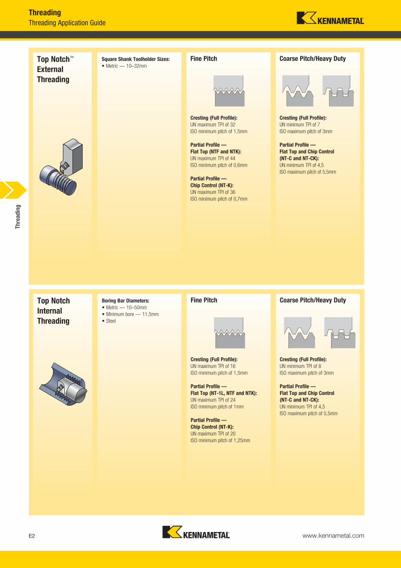
Cresting (Full Profile):UN maximum TPI of 32ISO minimum pitch of 1,5mm
Partial Profile — Flat Top (NTF and NTK):UN maximum TPI of 44ISO minimum pitch of 0,6mm
Partial Profile — Chip Control (NT-K):UN maximum TPI of 36ISO minimum pitch of 0,7mm
Coarse Pitch/Heavy Duty
Cresting (Full Profile):UN minimum TPI of 7ISO maximum pitch of 3mm
Partial Profile — Flat Top and Chip Control (NT-C and NT-CK):UN minimum TPI of 4,5ISO maximum pitch of 5,5mm
Top Notch™
ExternalThreading
Square Shank Toolholder Sizes:• Metric — 10–32mm
Fine Pitch
Cresting (Full Profile):UN maximum TPI of 16ISO minimum pitch of 1,5mm
Partial Profile — Flat Top (NT-1L, NTF and NTK):UN maximum TPI of 24ISO minimum pitch of 1mm
Partial Profile — Chip Control (NT-K):UN maximum TPI of 20ISO minimum pitch of 1,25mm
Coarse Pitch/Heavy Duty
Cresting (Full Profile):UN minimum TPI of 8ISO maximum pitch of 3mm
Partial Profile — Flat Top and Chip Control (NT-C and NT-CK):UN minimum TPI of 4,5ISO maximum pitch of 5,5mm
Top NotchInternalThreading
Boring Bar Diameters:• Metric — 10–50mm• Minimum bore — 11,5mm• Steel
Thre
adin
g
KM_Master12_Turning_E002_E003_Metric.qxp:Layout 1 3/6/12 2:08 PM Page E2
www.kennametal.com E3
Fine Pitch
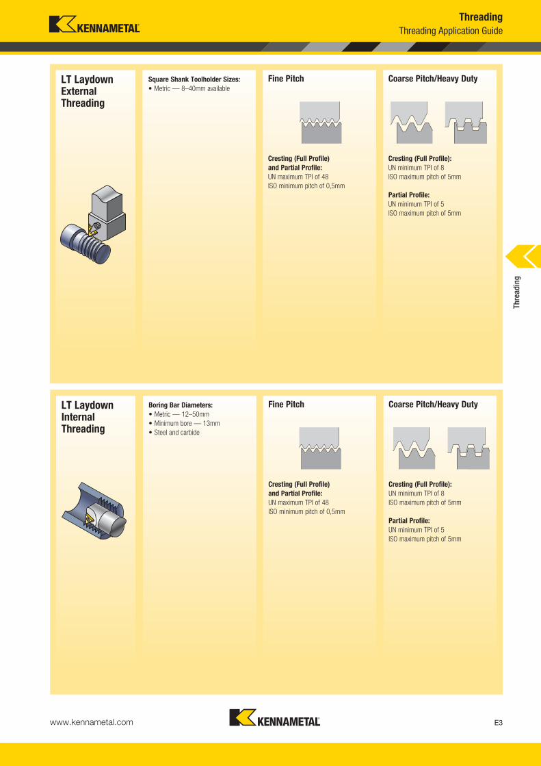
Cresting (Full Profile) and Partial Profile:UN maximum TPI of 48ISO minimum pitch of 0,5mm
Coarse Pitch/Heavy Duty
Cresting (Full Profile):UN minimum TPI of 8ISO maximum pitch of 5mm
Partial Profile:UN minimum TPI of 5ISO maximum pitch of 5mm
LT LaydownInternalThreading
Boring Bar Diameters:• Metric — 12–50mm• Minimum bore — 13mm• Steel and carbide
Fine Pitch
Cresting (Full Profile) and Partial Profile:UN maximum TPI of 48ISO minimum pitch of 0,5mm
Coarse Pitch/Heavy Duty
Cresting (Full Profile):UN minimum TPI of 8ISO maximum pitch of 5mm
Partial Profile:UN minimum TPI of 5ISO maximum pitch of 5mm
Square Shank Toolholder Sizes:• Metric — 8–40mm available
ThreadingThreading Application Guide
LT LaydownExternalThreading
Thre
adin
g
KM_Master12_Turning_E002_E003_Metric.qxp:Layout 1 3/6/12 2:08 PM Page E3

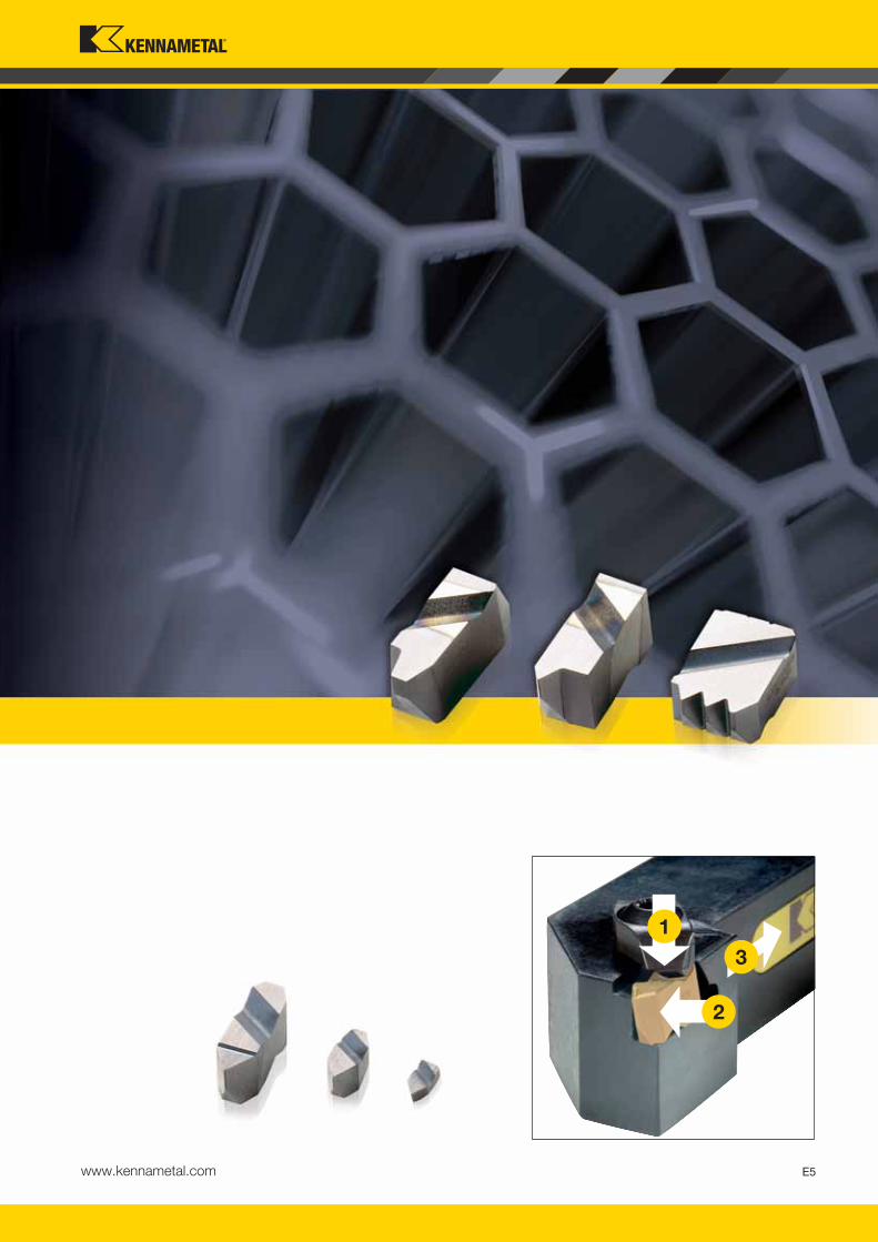
Primary ApplicationTop Notch Threading with Beyond™ Insert technology provides consistent tool performance and superior clamping thread toalmost any operation. With the largest selection of grades and geometries in the industry, the Top Notch Threading systemis a proven solution.
Choosing the Top Notch Threading System• A superior choice for heavy-duty applications like machining
of Acme, Buttress, and API threads. Top Notch is also the best system for coarse pitch and multitooth threading applications.
• Largest selection of insert geometries and grades in the industry.
• A very rigid insert clamping design ensures best tool life, surface finish, and workpiece quality.
• Simplicity of the Top Notch design does not require shim selection for thread helix angles. This helps to avoid mistakes on the shop floor.
• Reduces inventory by using the same Top Notch toolholders and boring bars with either threading or grooving inserts.
• Top Notch chipbreaker inserts eliminate long troublesome coils.
• An excellent choice for special thread forms and toolholder designs.
Precision-Ground Thread Form• Minimises built-up edge.
• Precisely cuts most common materials.
• Reduces cutting forces.
• Ensures accurate high-quality threads.
Superior Chip Control • Eliminates long, troublesome coils.
• Excellent for internal threading operations.
• Available in partial profile inserts for 60° thread forms.
Features and Benefits
Top Notch™ Thread Tooling Is the Proven High-Productivity Threading Solution!
www.kennametal.comE4
KM_Master12_Turning_E004_E005_Metric.qxp:Layout 1 3/6/12 2:08 PM Page E4
1
2
3
www.kennametal.com E5
KM_Master12_Turning_E004_E005_Metric.qxp:Layout 1 3/6/12 2:08 PM Page E5
www.kennametal.comE6
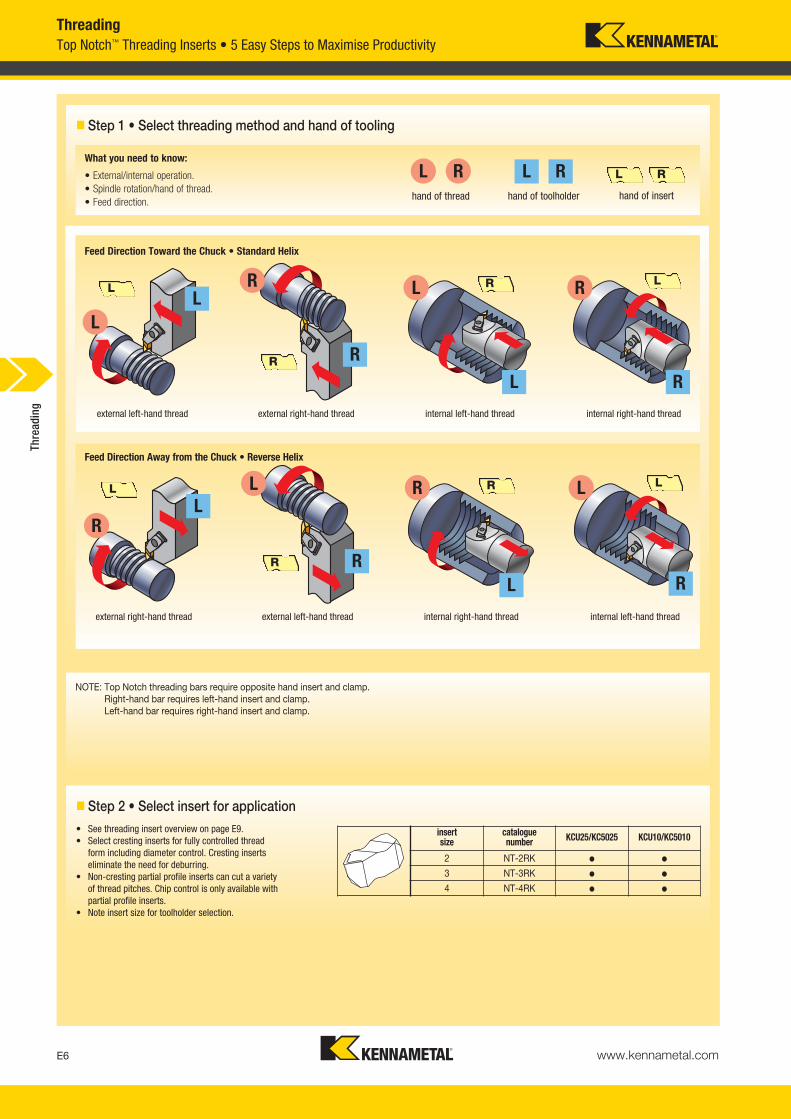
Top Notch™ Threading Inserts • 5 Easy Steps to Maximise ProductivityThreading
� Step 1 • Select threading method and hand of tooling
Feed Direction Away from the Chuck • Reverse Helix
Feed Direction Toward the Chuck • Standard Helix
What you need to know:
• External/internal operation.• Spindle rotation/hand of thread.• Feed direction. hand of thread hand of toolholder hand of insert
RLRLRL
L
R
L
RL
R
L R
L R LR
external left-hand thread external right-hand thread internal left-hand thread internal right-hand thread
L
R
L
R
L
R
L R
LR LR
external left-hand thread internal right-hand thread internal left-hand threadexternal right-hand thread
� Step 2 • Select insert for application• See threading insert overview on page E9.• Select cresting inserts for fully controlled thread
form including diameter control. Cresting inserts eliminate the need for deburring.
• Non-cresting partial profile inserts can cut a variety of thread pitches. Chip control is only available with partial profile inserts.
• Note insert size for toolholder selection.
NOTE: Top Notch threading bars require opposite hand insert and clamp.Right-hand bar requires left-hand insert and clamp.Left-hand bar requires right-hand insert and clamp.
insert size
catalogue number KCU25/KC5025 KCU10/KC5010
2 NT-2RK � �
3 NT-3RK � �
4 NT-4RK � �
Thre
adin
g
KM_Master12_Turning_E006_E007_Metric.qxp:Layout 1 3/6/12 2:08 PM Page E6

www.kennametal.com E7
ThreadingTop Notch™ Threading Inserts • 5 Easy Steps to Maximise Productivity
� Step 4 • Select holder from catalogue page
� Step 3 • Select grade and speed
� Step 5 • Select insert and holder from catalogue page
NOTE: Top Notch toolholders and boring bars are listed with a gage insert to indicate the size and hand required. They are compatible with both grooving and threadinginserts of the same size.
NOTE: Optimise your threading operation by using the proper infeed angle and the recommended infeed values.
NOTE: The insert size must match the gage insert size of your toolholder selection.
workpiece material P M K N S
insert style chip controlor neutral
chip control or positive neutral positive positive
optimum cutting conditions
KCU10/KC501050–230
KCU10/KC501050–185
KCU10/KC501070–210
KC541070–390
KCU10/KC501020–120
first choice KCU25/KC502540–200
KCU25/KC502540–135
KCU25/KC502560–145
KCU25/KC502550–360
KCU25/KC502510–100
Recommendations for Grade and Speed Selection • m/min
Top Notch Threading ExampleApplication ........................................8 TPI Acme internal
right-hand threadMaterial ............................................................alloy steelWorkpiece diameter ..........................................114,3mm
good cutting conditionsfeed toward the chuck
ExampleChip control ................................................................NT-K or NT-CK (partial profile only)Neutral ......................................NT, NT-C, NTF, NTC, NJ, NJF, NDC-V, NA, NDC, NTB-A/BPositive ..............................................................................................NTP, NTK, NJP, NJK
RecommendationInsert ....................................................................NA3L8Grade ..................................................................KC5010Insert size ......................................................................3Boring bar ..................................................A50UNNTOR4 Gage insert................................................................N.3LSpeed..............................................................150 m/minInfeed passes ..................................................12 passes
Select the Appropriate Holder for the Insert Size and Hand:
catalogue number gage insert
NSR-163D N.3R
NSR-164D N.4R
What you need to know: • External/internal operation.
• Minimum bore diameter (for internal operations).
• Hand of tool.
• Insert size (gage insert).
Thre
adin
g
KM_Master12_Turning_E006_E007_Metric.qxp:Layout 1 3/6/12 2:08 PM Page E7
www.kennametal.comE8
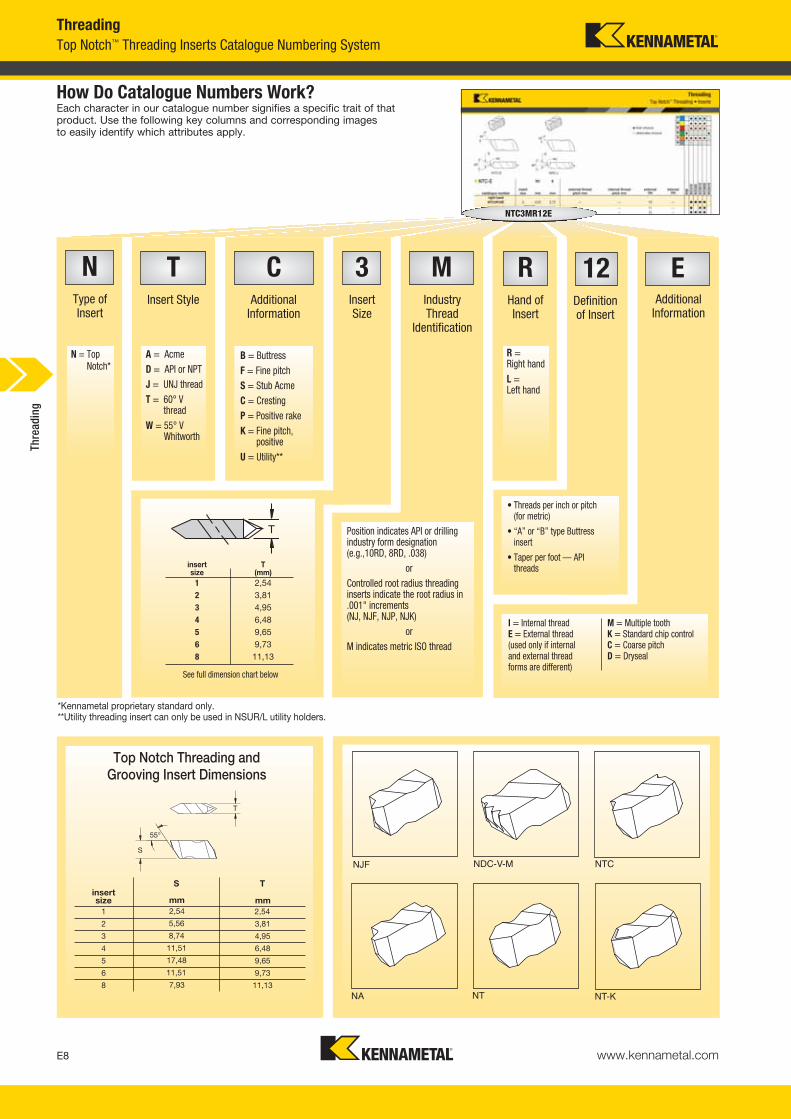
ThreadingTop Notch™ Threading Inserts Catalogue Numbering System
*Kennametal proprietary standard only.**Utility threading insert can only be used in NSUR/L utility holders.
NJF NDC-V-M NTC
NA NT NT-K
12Definitionof Insert
RHand ofInsert
MIndustryThread
Identification
CAdditional
Information
TInsert Style
NType of Insert
B = ButtressF = Fine pitchS = Stub AcmeC = CrestingP = Positive rakeK = Fine pitch,
positiveU = Utility**
R =Right handL =Left hand
N = TopNotch*
A = AcmeD = API or NPTJ = UNJ threadT = 60° V
threadW = 55° V
Whitworth
NTC3MR12E
EAdditional
Information
3Insert Size
insert size
T (mm)
1 2,542 3,813 4,954 6,485 9,656 9,738 11,13
See full dimension chart below
• Threads per inch or pitch(for metric)
• “A” or “B” type Buttressinsert
• Taper per foot — APIthreads
I = Internal threadE = External thread (used only if internal and external thread forms are different)
M = Multiple toothK = Standard chip controlC = Coarse pitchD = Dryseal
Position indicates API or drillingindustry form designation (e.g.,10RD, 8RD, .038)
orControlled root radius threadinginserts indicate the root radius in.001" increments (NJ, NJF, NJP, NJK)
orM indicates metric ISO thread
Top Notch Threading andGrooving Insert Dimensions
insertsize
S T
mm1 2,54
2 3,81
3 4,95
4 6,48
5 9,65
6 9,73
8 11,13
mm2,54
5,56
8,74
11,51
17,48
11,51
7,93
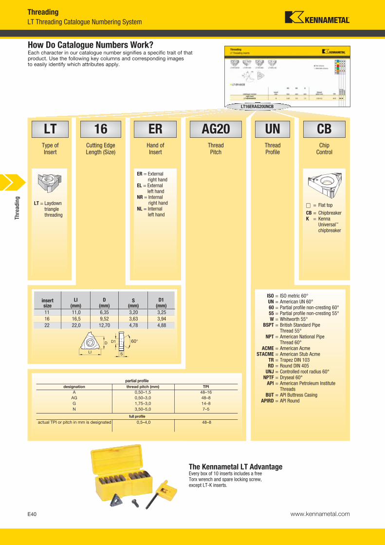
How Do Catalogue Numbers Work?Each character in our catalogue number signifies a specific trait of thatproduct. Use the following key columns and corresponding imagesto easily identify which attributes apply.
Thre
adin
g
KM_Master12_Turning_E008_E009_Metric.qxp:Layout 1 3/6/12 2:08 PM Page E8

www.kennametal.com E9
Threading
style
thread profile standard
tolerance class cresting application page(s)
chip control — K neutral positive
Partial Profile 60º — — NGeneral use for 60º thread forms such as ISO and UNwhere non-cresting inserts are desired to cut a variety
of pitchesE10–E11
NT-K NT NTP
Partial Profile 60º — coarse pitch — — N
Coarse pitch 60º thread forms such as ISO and UN where non-cresting inserts are desired to cut a variety
of pitchesE11
NT-CK
Partial Profile 60º— fine pitch — — N
Fine pitch 60º thread forms such as ISO and UN where non-cresting inserts are desired to cut a variety
of pitches — able to thread close to shouldersE11–E12
NTF NTK
Partial Profile 60º— four-edged insert — — N
Four-edged insert for 60º partial profile threading —requires NSU-style toolholder for size 4U insert E12
NTU
Metric ISO ISO R262,DIN 13 6g/6H Y
Widely used metric 60º V-form for all industriesE12
NTC-M
American UN ANSI B1.1:03 2A/2B YWidely used inch-based 60º V-form for all industries
E12–E13
NTC
UNJ MIL-S-8879C 3A/3B NControlled root radius on external threads for military and
aerospace industries E14
NJ NJP
UNJ— fine pitch MIL-S-8879C 3A/3B N
Controlled root radius on external threads for military andaerospace industries — able to thread close to shoulders E15
NJF NJK
NPT ANSI B2.1:83 StandardNPT Y
National Pipe Thread standard forms for pipe fittingsE16
NDC-V
NPT— multitooth ANSI B2.1:83 Standard
NPT YHigh productivity multitooth threading inserts
for NPT threads E16
NDC-V-M
Whitworth, BSW, BSPBS 84:1956,
ISO 228/1:1982,DIN 259
MediumClass A Y
Widely used 55º form for gas and water connectionsE17
NWC
API Rotary Shoulder Connections — partial profile
API SPEC. 7:1990 StandardAPI N
60º V-form used for rotary shoulder pipe connections in the oil and gas industry including V-.038R, V-.040,
and V-.050 forms E17
ND
API Rotary Shoulder Connections —
crestingAPI SPEC. 7:1990 Standard
API Y60º V-form used for rotary shoulder pipe connections inthe oil and gas industry including V-.038R, V-.040, andV-.050 forms — complete cresting form including taper
E18
NDC
API Round API STD. 5B:1979 StandardAPI RD Y
60º V-form with large radius for casing, tubing, and line pipe in the oil and gas industry including
8 and 10 round formsE18
NDC-RD
API Round— multitooth API STD. 5B:1979 Standard
API RD YHigh productivity multitooth threading inserts
for API round threads E18
NDC-RD-M
Acme ANSI B1.5:1988 3G N29º truncated thread form for motion applications
in a wide variety of industries E19
NA
Stub Acme ANSI B1.8:1988 2G NShallow depth 29º truncated thread form for motion
applications in a wide variety of industries E20
NAS
American Buttress7º pressure flank leading
(Push)ANSI B1.9:1973 Class 2 N
Sawtooth form for axial load bearing applications in a variety of industries — use the “A” style when
the 7º pressure flank is the leading edgeE20
NTB-A
American Buttress 45º clearance flank leading
(Pull)ANSI B1.9:1973 Class 2 N
Sawtooth form for axial load bearing applications in a variety of industries — use the “B” style when
the 45º clearance flank is the leading edgeE21
NTB-B
Top Notch™ Threading Inserts • Insert Overview
Thre
adin
g
KM_Master12_Turning_E008_E009_Metric.qxp:Layout 1 3/6/12 2:08 PM Page E9
www.kennametal.comE10
60°
60°
P � � � �
M � � � �
K � � � � �
N � � � � � �
S � � � � � �
H � �
RC E
catalogue numberinsertsize mm mm
external threadpitch mm
internal threadpitch mm
external TPI
internal TPI K
68K
CU
10K
CU
25K
C50
10K
C50
25K
C54
10
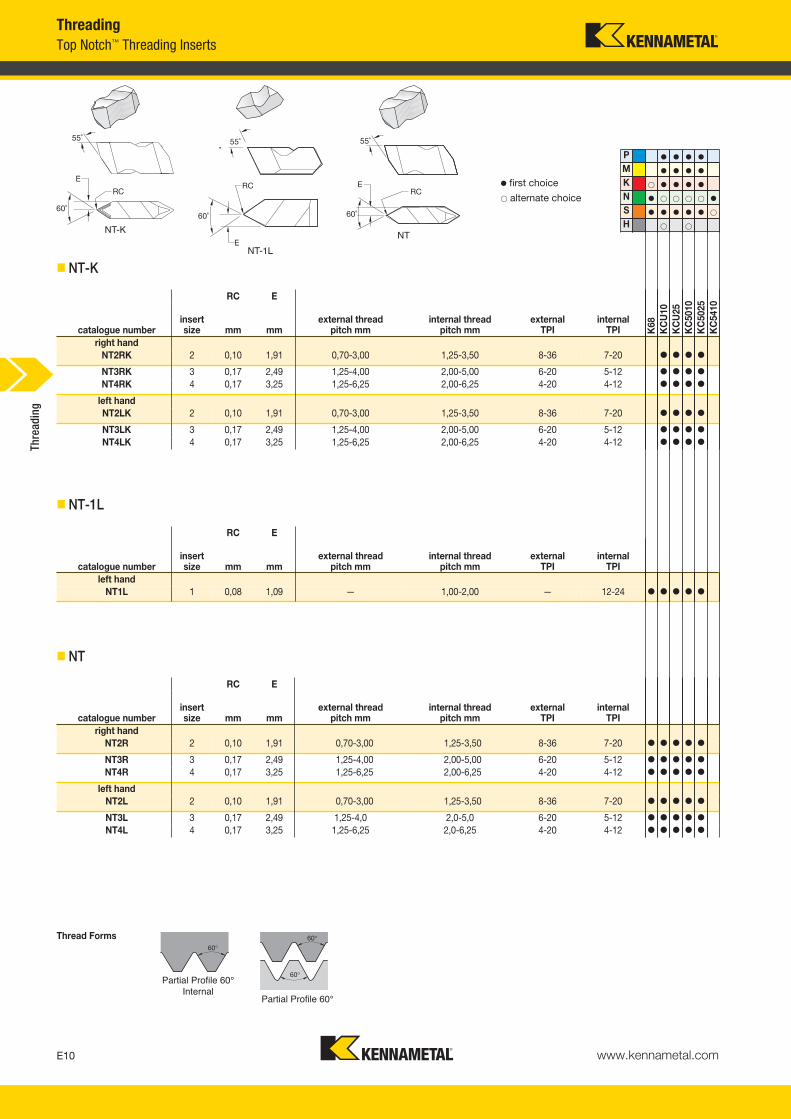
right handNT2RK 2 0,10 1,91 0,70-3,00 1,25-3,50 8-36 7-20 � � � �
NT3RK 3 0,17 2,49 1,25-4,00 2,00-5,00 6-20 5-12 � � � �
NT4RK 4 0,17 3,25 1,25-6,25 2,00-6,25 4-20 4-12 � � � �
left handNT2LK 2 0,10 1,91 0,70-3,00 1,25-3,50 8-36 7-20 � � � �
NT3LK 3 0,17 2,49 1,25-4,00 2,00-5,00 6-20 5-12 � � � �
NT4LK 4 0,17 3,25 1,25-6,25 2,00-6,25 4-20 4-12 � � � �
Partial Profile 60°
� first choice� alternate choice
Thread Forms
� NT-K
60°
RC E
catalogue numberinsertsize mm mm
external threadpitch mm
internal threadpitch mm
external TPI
internal TPI
left handNT1L 1 0,08 1,09 — 1,00-2,00 — 12-24 � � � � �
Partial Profile 60°Internal
� NT-1L
� NT
NT-K
NT-1L
NT
ThreadingTop Notch™ Threading Inserts
RC E
catalogue numberinsert size mm mm
external threadpitch mm
internal threadpitch mm
external TPI
internal TPI
right handNT2R 2 0,10 1,91 0,70-3,00 1,25-3,50 8-36 7-20 � � � � �
NT3R 3 0,17 2,49 1,25-4,00 2,00-5,00 6-20 5-12 � � � � �
NT4R 4 0,17 3,25 1,25-6,25 2,00-6,25 4-20 4-12 � � � � �
left handNT2L 2 0,10 1,91 0,70-3,00 1,25-3,50 8-36 7-20 � � � � �
NT3L 3 0,17 2,49 1,25-4,0 2,0-5,0 6-20 5-12 � � � � �
NT4L 4 0,17 3,25 1,25-6,25 2,0-6,25 4-20 4-12 � � � � �
Thre
adin
g
KM_Master12_Turning_E010_E011_Metric.qxp:Layout 1 3/6/12 2:09 PM Page E10
www.kennametal.com E11
P � � � �
M � � � �
K � � � � �
N � � � � � �
S � � � � � �
H � �
� first choice� alternate choice
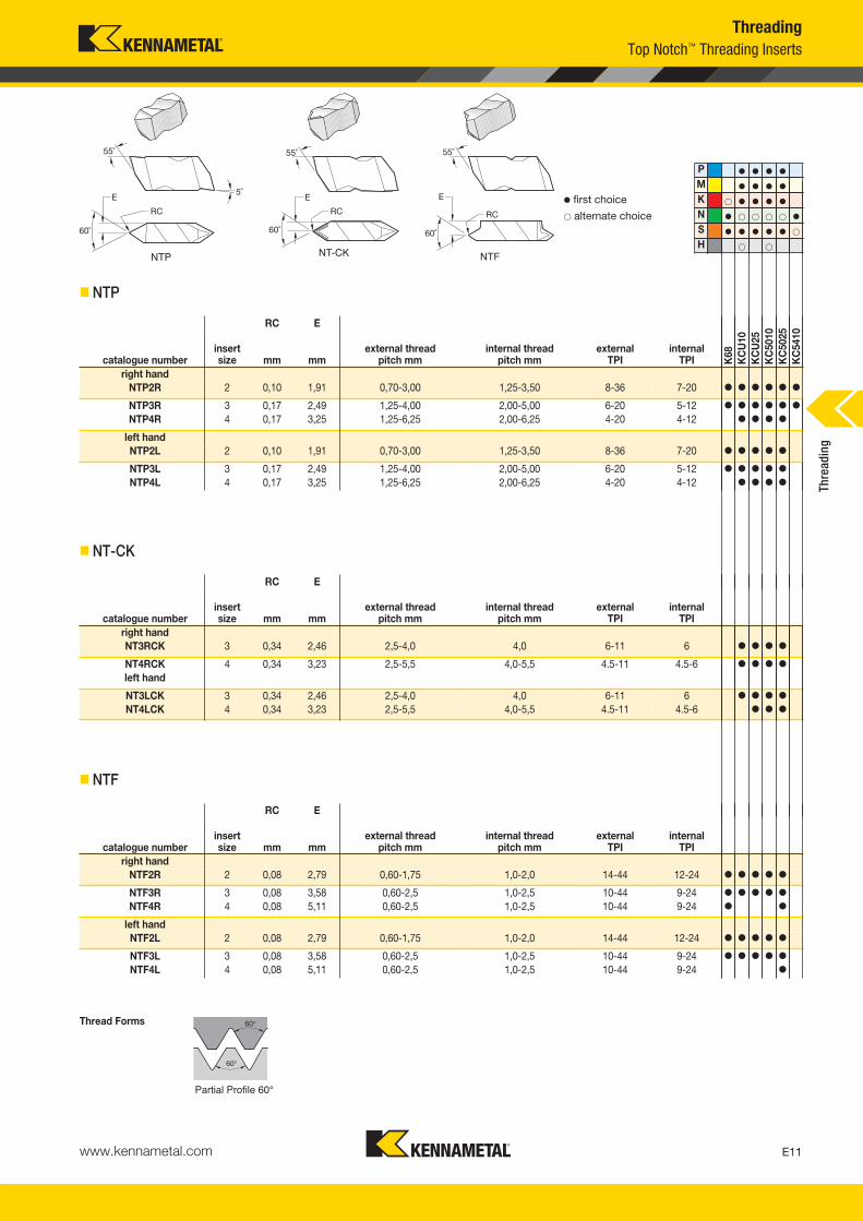
� NTP
RC E
catalogue numberinsertsize mm mm
external threadpitch mm
internal threadpitch mm
external TPI
internal TPI
right handNT3RCK 3 0,34 2,46 2,5-4,0 4,0 6-11 6 � � � �
NT4RCK 4 0,34 3,23 2,5-5,5 4,0-5,5 4.5-11 4.5-6 � � � �
left hand
NT3LCK 3 0,34 2,46 2,5-4,0 4,0 6-11 6 � � � �
NT4LCK 4 0,34 3,23 2,5-5,5 4,0-5,5 4.5-11 4.5-6 � � �
� NT-CK
60°
60°
RC E
catalogue numberinsertsize mm mm
external threadpitch mm
internal threadpitch mm
external TPI
internal TPI
right handNTF2R 2 0,08 2,79 0,60-1,75 1,0-2,0 14-44 12-24 � � � � �
NTF3R 3 0,08 3,58 0,60-2,5 1,0-2,5 10-44 9-24 � � � � �
NTF4R 4 0,08 5,11 0,60-2,5 1,0-2,5 10-44 9-24 � �
left handNTF2L 2 0,08 2,79 0,60-1,75 1,0-2,0 14-44 12-24 � � � � �
NTF3L 3 0,08 3,58 0,60-2,5 1,0-2,5 10-44 9-24 � � � � �
NTF4L 4 0,08 5,11 0,60-2,5 1,0-2,5 10-44 9-24 �
Partial Profile 60°
Thread Forms
� NTF
NTP NT-CK NTF
ThreadingTop Notch™ Threading Inserts
RC E
catalogue numberinsert size mm mm
external threadpitch mm
internal threadpitch mm
external TPI
internal TPI K
68K
CU
10K
CU
25K
C50
10K
C50
25K
C54
10
right handNTP2R 2 0,10 1,91 0,70-3,00 1,25-3,50 8-36 7-20 � � � � � �
NTP3R 3 0,17 2,49 1,25-4,00 2,00-5,00 6-20 5-12 � � � � � �
NTP4R 4 0,17 3,25 1,25-6,25 2,00-6,25 4-20 4-12 � � � �
left handNTP2L 2 0,10 1,91 0,70-3,00 1,25-3,50 8-36 7-20 � � � � �
NTP3L 3 0,17 2,49 1,25-4,00 2,00-5,00 6-20 5-12 � � � � �
NTP4L 4 0,17 3,25 1,25-6,25 2,00-6,25 4-20 4-12 � � � � Thre
adin
g
KM_Master12_Turning_E010_E011_Metric.qxp:Layout 1 3/6/12 2:09 PM Page E11

NTC-M-E
www.kennametal.comE12
60°
60°
P � � � �
M � � � �
K � � � � �
N � � � � � �
S � � � � � �
H � �
RC E
catalogue numberinsertsize mm mm
external threadpitch mm
internal threadpitch mm
external TPI
internal TPI K
68K
CU
10K
CU
25K
C50
10K
C50
25K
C54
10
right handNTK2R 2 0,08 2,79 0,60-1,75 1,00-2,00 14-44 12-24 � � � � �
NTK3R 3 0,08 3,58 0,60-2,50 1,00-2,50 10-44 9-24 � � � � �
left hand
NTK2L 2 0,08 2,79 0,60-1,75 1,00-2,00 14-44 12-24 � � � � �
NTK3L 3 0,08 3,58 0,60-2,50 1,00-2,50 10-44 9-24 � � � � �
Partial Profile 60°
� first choice� alternate choice
� NTK
60°
RC E
catalogue numberinsertsize mm mm
external threadpitch mm
internal threadpitch mm
external TPI
internal TPI
right handNTU4R 4U 0,11 3,18 1,25-6,25 — 4-20 — � �
Partial Profile60° External
� NTU
60°
1/8P
RC E
catalogue numberinsertsize mm mm
external threadpitch mm
internal threadpitch mm
external TPI
internal TPI
right handNTC3MR150E 3 0,20 3,68 1,50 — — — � � �
NTC3MR200E 3 0,27 3,68 2,00 — — — � �
ISO Metric-External
Thread Forms
� NTC-M-E
NTKNTU
ThreadingTop Notch™ Threading Inserts
Thre
adin
g
KM_Master12_Turning_E012_E013_Metric.qxp:Layout 1 3/6/12 2:09 PM Page E12
www.kennametal.com E13
60°
1/8P
P � � � �
M � � � �
K � � � � �
N � � � � � �
S � � � � � �
H � �
RC E
catalogue numberinsertsize mm mm
external threadpitch mm
internal threadpitch mm
externalTPI
internal TPI K
68K
CU
10K
CU
25K
C50
10K
C50
25K
C54
10
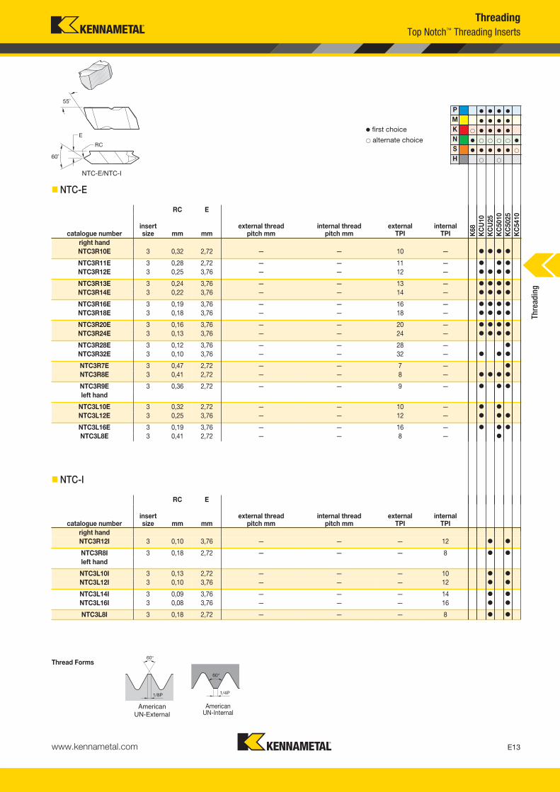
right handNTC3R10E 3 0,32 2,72 — — 10 — � � � �
NTC3R11E 3 0,28 2,72 — — 11 — � � �
NTC3R12E 3 0,25 3,76 — — 12 — � � � �
NTC3R13E 3 0,24 3,76 — — 13 — � � � �
NTC3R14E 3 0,22 3,76 — — 14 — � � � �
NTC3R16E 3 0,19 3,76 — — 16 — � � � �
NTC3R18E 3 0,18 3,76 — — 18 — � � � �
NTC3R20E 3 0,16 3,76 — — 20 — � � � �
NTC3R24E 3 0,13 3,76 — — 24 — � � � �
NTC3R28E 3 0,12 3,76 — — 28 — �
NTC3R32E 3 0,10 3,76 — — 32 — � � �
NTC3R7E 3 0,47 2,72 — — 7 — �
NTC3R8E 3 0,41 2,72 — — 8 — � � � �
NTC3R9E 3 0,36 2,72 — — 9 — � � �
left hand
NTC3L10E 3 0,32 2,72 — — 10 — � �
NTC3L12E 3 0,25 3,76 — — 12 — � � �
NTC3L16E 3 0,19 3,76 — — 16 — � � �
NTC3L8E 3 0,41 2,72 — — 8 — �
American UN-External
� first choice� alternate choice
� NTC-E
60°
1/4P
RC E
catalogue numberinsertsize mm mm
external threadpitch mm
internal threadpitch mm
external TPI
internal TPI
right handNTC3R12I 3 0,10 3,76 — — — 12 � �
NTC3R8I 3 0,18 2,72 — — — 8 � �
left hand
NTC3L10I 3 0,13 2,72 — — — 10 � �
NTC3L12I 3 0,10 3,76 — — — 12 � �
NTC3L14I 3 0,09 3,76 — — — 14 � �
NTC3L16I 3 0,08 3,76 — — — 16 � �
NTC3L8I 3 0,18 2,72 — — — 8 � �
American UN-Internal
Thread Forms
� NTC-I
NTC-E/NTC-I
ThreadingTop Notch™ Threading Inserts
Thre
adin
g
KM_Master12_Turning_E012_E013_Metric.qxp:Layout 1 3/6/12 2:09 PM Page E13
www.kennametal.comE14
60°
1/8P
Rmax.1804PRmin .1501P
P � � � �
M � � � �
K � � � � �
N � � � � � �
S � � � � � �
H � �
RC E
catalogue numberinsertsize mm mm
external threadpitch mm
internal threadpitch mm
externalTPI
internal TPI K
68K
CU
10K
CU
25K
C50
10K
C50
25K
C54
10
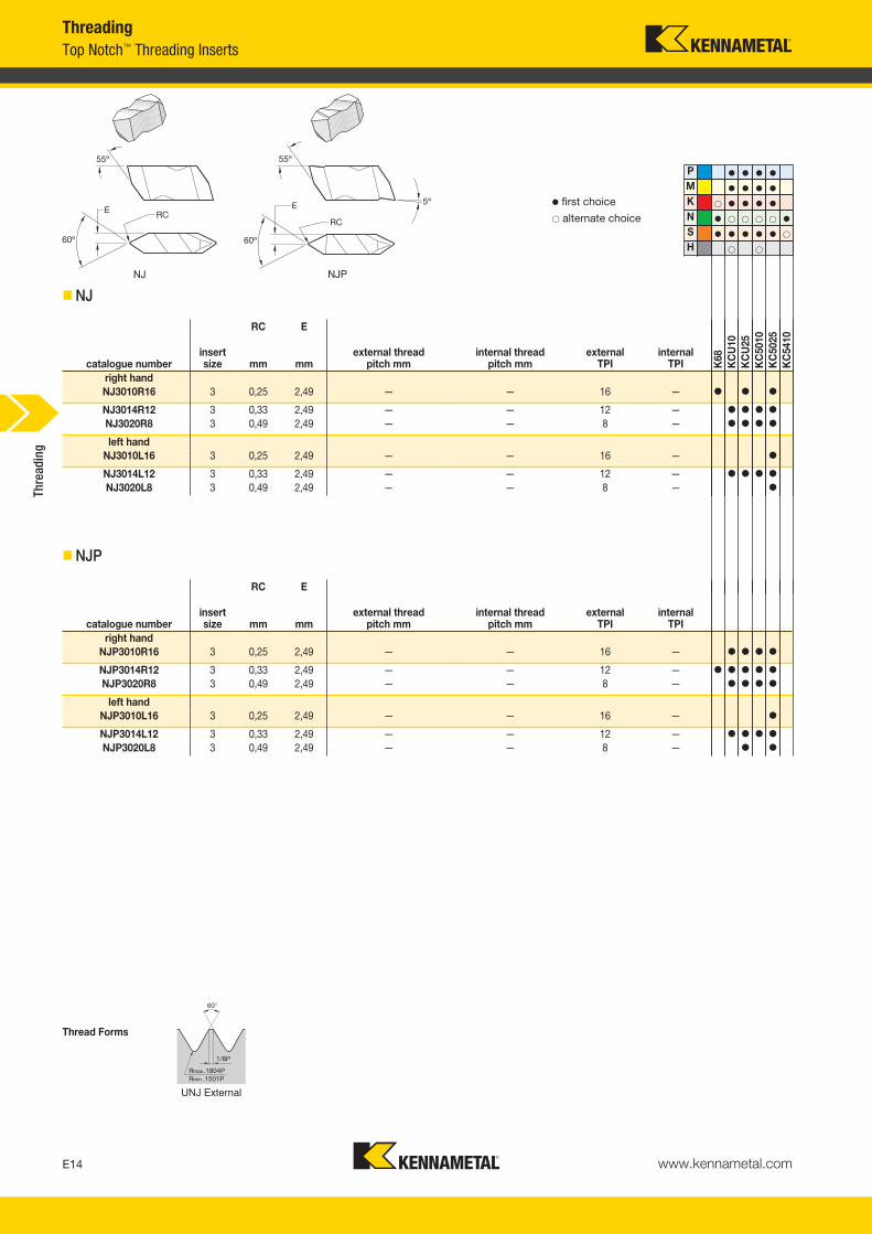
right handNJ3010R16 3 0,25 2,49 — — 16 — � � �
NJ3014R12 3 0,33 2,49 — — 12 — � � � �
NJ3020R8 3 0,49 2,49 — — 8 — � � � �
left handNJ3010L16 3 0,25 2,49 — — 16 — �
NJ3014L12 3 0,33 2,49 — — 12 — � � � �
NJ3020L8 3 0,49 2,49 — — 8 — �
UNJ External
� first choice� alternate choice
� NJ
RC E
catalogue numberinsertsize mm mm
external threadpitch mm
internal threadpitch mm
externalTPI
internal TPI
right handNJP3010R16 3 0,25 2,49 — — 16 — � � � �
NJP3014R12 3 0,33 2,49 — — 12 — � � � � �
NJP3020R8 3 0,49 2,49 — — 8 — � � � �
left handNJP3010L16 3 0,25 2,49 — — 16 — �
NJP3014L12 3 0,33 2,49 — — 12 — � � � �
NJP3020L8 3 0,49 2,49 — — 8 — � �
Thread Forms
� NJP
NJ NJP
ThreadingTop Notch™ Threading Inserts
Thre
adin
g
KM_Master12_Turning_E014_E015_Metric.qxp:Layout 1 3/6/12 2:09 PM Page E14

www.kennametal.com E15
P � � � �
M � � � �
K � � � � �
N � � � � � �
S � � � � � �
H � �
� first choice� alternate choice
� NJF
60°
1/8P
R max.1804PR min .1501P
RC E
catalogue numberinsertsize mm mm
external threadpitch mm
internal threadpitch mm
externalTPI
internal TPI
right handNJK3005R32 3 0,13 3,58 — — 32 — � � � �
NJK3006R28 3 0,15 3,58 — — 28 — � � � �
NJK3007R24 3 0,17 3,58 — — 24 — � � � �
NJK3008R20 3 0,20 3,58 — — 20 — � � � �
NJK3009R18 3 0,22 3,58 — — 18 — � � � �
NJK3010R16 3 0,25 3,58 — — 16 — � � � � �
NJK3012R14 3 0,28 3,58 — — 14 — � � �
left handNJK3005L32 3 0,13 3,58 — — 32 — �
NJK3006L28 3 0,15 3,58 — — 28 — �
NJK3008L20 3 0,20 3,58 — — 20 — � �
NJK3012L14 3 0,28 3,58 — — 14 — �
UNJ External
Thread Forms
� NJK
RC E
catalogue numberinsertsize mm mm
external threadpitch mm
internal threadpitch mm
externalTPI
internal TPI K
68K
CU
10K
CU
25K
C50
10K
C50
25K
C54
10
right handNJF3005R32 3 0,13 3,58 — — 32 — � �
NJF3006R28 3 0,15 3,58 — — 28 — � � � �
NJF3007R24 3 0,17 3,58 — — 24 — � � � �
NJF3008R20 3 0,20 3,58 — — 20 — � � � �
NJF3009R18 3 0,22 3,58 — — 18 — � � � � �
NJF3010R16 3 0,25 3,58 — — 16 — � � � � �
NJF3012R14 3 0,28 3,58 — — 14 — � � � �
left handNJF3007L24 3 0,17 3,58 — — 24 — �
NJF3008L20 3 0,20 3,58 — — 20 — �
NJF3009L18 3 0,22 3,58 — — 18 — �
NJF NJK
ThreadingTop Notch™ Threading Inserts
Thre
adin
g
KM_Master12_Turning_E014_E015_Metric.qxp:Layout 1 3/6/12 2:09 PM Page E15
www.kennametal.comE16
P � � � �
M � � � �
K � � � � �
N � � � � � �
S � � � � � �
H � �
RC E
catalogue numberinsert size mm mm TPI K
68K
CU
10K
CU
25K
C50
10K
C50
25K
C54
10
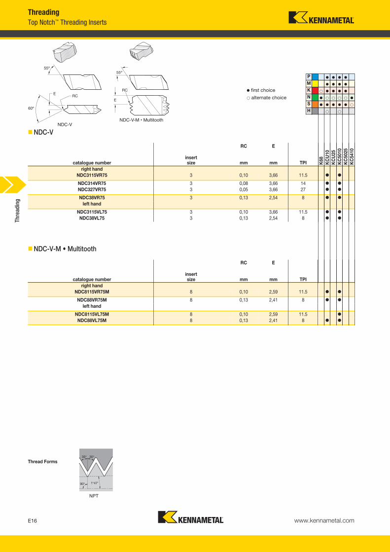
right handNDC3115VR75 3 0,10 3,66 11.5 � �
NDC314VR75 3 0,08 3,66 14 � �
NDC327VR75 3 0,05 3,66 27 � �
NDC38VR75 3 0,13 2,54 8 � �
left hand
NDC3115VL75 3 0,10 3,66 11.5 � �
NDC38VL75 3 0,13 2,54 8 � �
� first choice� alternate choice
� NDC-V
30°
90° 1°47'
30°
RC E
catalogue numberinsert size mm mm TPI
right handNDC8115VR75M 8 0,10 2,59 11.5 � �
NDC88VR75M 8 0,13 2,41 8 � �
left hand
NDC8115VL75M 8 0,10 2,59 11.5 �
NDC88VL75M 8 0,13 2,41 8 � �
NPT
Thread Forms
� NDC-V-M • Multitooth
NDC-VNDC-V-M • Multitooth
ThreadingTop Notch™ Threading Inserts
Thre
adin
g
KM_Master12_Turning_E016_E017_Metric.qxp:Layout 1 3/6/12 2:09 PM Page E16
www.kennametal.com E17
55°
0,1373P
P � � � �
M � � � �
K � � � � �
N � � � � � �
S � � � � � �
H � �
RC E
catalogue numberinsert size mm mm TPI K
68K
CU
10K
CU
25K
C50
10K
C50
25K
C54
10
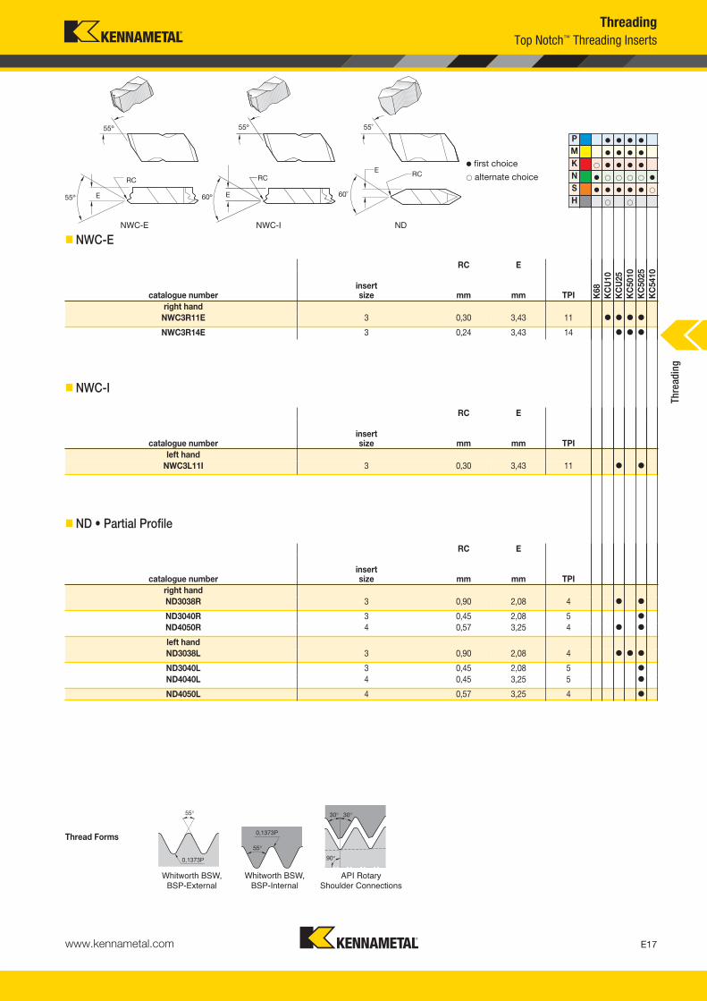
right handNWC3R11E 3 0,30 3,43 11 � � � �
NWC3R14E 3 0,24 3,43 14 � � �
Whitworth BSW, BSP-External
� first choice� alternate choice
� NWC-E
0,1373P
55°
RC E
catalogue numberinsert size mm mm TPI
left handNWC3L11I 3 0,30 3,43 11 � �
Whitworth BSW, BSP-Internal
� NWC-I
30°
90°
30°
RC E
catalogue numberinsert size mm mm TPI
right handND3038R 3 0,90 2,08 4 � �
ND3040R 3 0,45 2,08 5 �
ND4050R 4 0,57 3,25 4 � �
left handND3038L 3 0,90 2,08 4 � � �
ND3040L 3 0,45 2,08 5 �
ND4040L 4 0,45 3,25 5 �
ND4050L 4 0,57 3,25 4 �
API Rotary Shoulder Connections
Thread Forms
� ND • Partial Profile
NWC-E NWC-I ND
Top Notch™ Threading InsertsThreading
Thre
adin
g
KM_Master12_Turning_E016_E017_Metric.qxp:Layout 1 3/6/12 2:10 PM Page E17
www.kennametal.comE18
30°
90°
30°
=1/2arctg (tpf/12)α
α
P � � � �
M � � � �
K � � � � �
N � � � � � �
S � � � � � �
H � �
RC E
catalogue numberinsert size mm mm TPI K
68K
CU
10K
CU
25K
C50
10K
C50
25K
C54
10
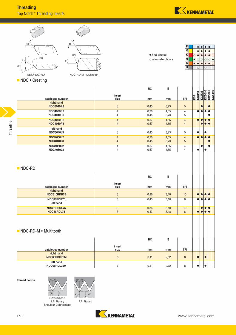
right handNDC3040R3 3 0,45 3,73 5 � �
NDC4038R2 4 0,90 4,65 4 � � � �
NDC4040R3 4 0,45 3,73 5 �
NDC4050R2 4 0,57 4,65 4 � � � �
NDC4050R3 4 0,57 4,65 4 � � �
left handNDC3040L3 3 0,45 3,73 5 � �
NDC4038L2 4 0,90 4,65 4 � � � �
NDC4040L3 4 0,45 3,73 5 �
NDC4050L2 4 0,57 4,65 4 � �
NDC4050L3 4 0,57 4,65 4 � �
API Rotary Shoulder Connections
� first choice� alternate choice
� NDC • Cresting
RC E
catalogue numberinsert size mm mm TPI
right handNDC310RDR75 3 0,36 3,18 10 � � � �
NDC38RDR75 3 0,43 3,18 8 � � � �
left hand
NDC310RDL75 3 0,36 3,18 10 � � �
NDC38RDL75 3 0,43 3,18 8 � � � �
� NDC-RD
30°
90°
30°
1°47´
55˚
RC
E
RC E
catalogue numberinsert size mm mm TPI
right handNDC68RDR75M 6 0,41 2,62 8 � �
left handNDC68RDL75M 6 0,41 2,62 8 � �
API Round
Thread Forms
� NDC-RD-M • Multitooth
NDC/NDC-RD NDC-RD-M • Multitooth
ThreadingTop Notch™ Threading Inserts
Thre
adin
g
KM_Master12_Turning_E018_E019_Metric.qxp:Layout 1 3/6/12 2:10 PM Page E18
www.kennametal.com E19
29°
29°
P � � � �
M � � � �
K � � � � �
N � � � � � �
S � � � � � �
H � �
Acme
� first choice� alternate choice
Thread Forms
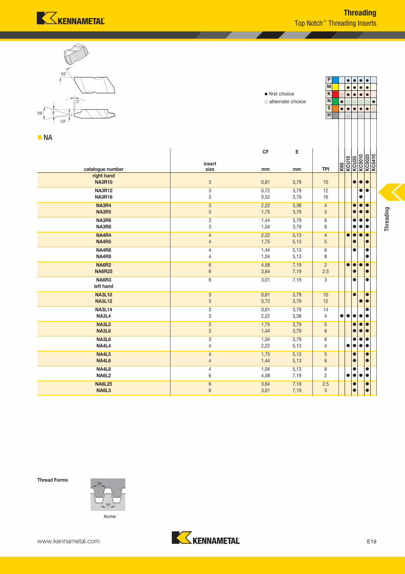
� NA
ThreadingTop Notch™ Threading Inserts
CF E
catalogue numberinsert size mm mm TPI K
68K
CU
10K
CU
25K
C50
10K
C50
25K
C54
10
right handNA3R10 3 0,81 3,79 10 � � �
NA3R12 3 0,72 3,79 12 � �
NA3R16 3 0,52 3,79 16 �
NA3R4 3 2,22 3,38 4 � � �
NA3R5 3 1,75 3,79 5 � � �
NA3R6 3 1,44 3,79 6 � � �
NA3R8 3 1,04 3,79 8 � � �
NA4R4 4 2,22 5,13 4 � � � �
NA4R5 4 1,75 5,13 5 � �
NA4R6 4 1,44 5,13 6 � �
NA4R8 4 1,04 5,13 8 �
NA6R2 6 4,58 7,19 2 � � � �
NA6R25 6 3,64 7,19 2.5 � �
NA6R3 6 3,01 7,19 3 � �
left hand
NA3L10 3 0,81 3,79 10 � �
NA3L12 3 0,72 3,79 12 � �
NA3L14 3 0,61 3,79 14 �
NA3L4 3 2,22 3,38 4 � � � � �
NA3L5 3 1,75 3,79 5 � � �
NA3L6 3 1,44 3,79 6 � � �
NA3L8 3 1,04 3,79 8 � � �
NA4L4 4 2,22 5,13 4 � � � �
NA4L5 4 1,75 5,13 5 � �
NA4L6 4 1,44 5,13 6 � �
NA4L8 4 1,04 5,13 8 � �
NA6L2 6 4,58 7,19 2 � � � �
NA6L25 6 3,64 7,19 2.5 � �
NA6L3 6 3,01 7,19 3 � �Th
read
ing
KM_Master12_Turning_E018_E019_Metric.qxp:Layout 1 3/6/12 2:10 PM Page E19
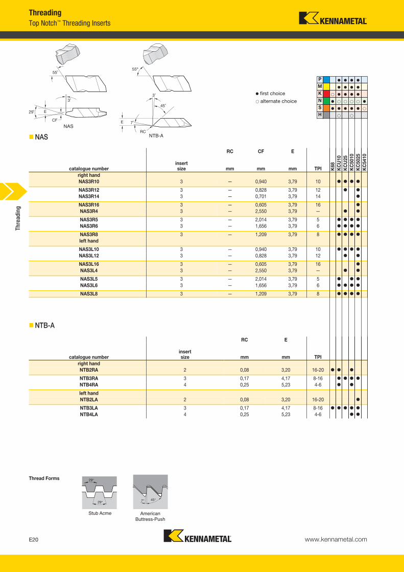
� NAS
www.kennametal.comE20
29°
29°
P � � � �
M � � � �
K � � � � �
N � � � � � �
S � � � � � �
H � �
RC CF E
catalogue numberinsert size mm mm mm TPI K
68K
CU
10K
CU
25K
C50
10K
C50
25K
C54
10
right handNAS3R10 3 — 0,940 3,79 10 � � � �
NAS3R12 3 — 0,828 3,79 12 � �
NAS3R14 3 — 0,701 3,79 14 �
NAS3R16 3 — 0,605 3,79 16 �
NAS3R4 3 — 2,550 3,79 — � �
NAS3R5 3 — 2,014 3,79 5 � � � �
NAS3R6 3 — 1,656 3,79 6 � � � �
NAS3R8 3 — 1,209 3,79 8 � � � �
left hand
NAS3L10 3 — 0,940 3,79 10 � � � �
NAS3L12 3 — 0,828 3,79 12 � �
NAS3L16 3 — 0,605 3,79 16 �
NAS3L4 3 — 2,550 3,79 — � �
NAS3L5 3 — 2,014 3,79 5 � � �
NAS3L6 3 — 1,656 3,79 6 � � � �
NAS3L8 3 — 1,209 3,79 8 � � � �
Stub Acme
� first choice� alternate choice
7° 45°
RC E
catalogue numberinsert size mm mm TPI
right handNTB2RA 2 0,08 3,20 16-20 � � �
NTB3RA 3 0,17 4,17 8-16 � � � �
NTB4RA 4 0,25 5,23 4-6 � �
left handNTB2LA 2 0,08 3,20 16-20 �
NTB3LA 3 0,17 4,17 8-16 � � � � �
NTB4LA 4 0,25 5,23 4-6 � �
American Buttress-Push
Thread Forms
� NTB-A
NAS
NTB-A
ThreadingTop Notch™ Threading Inserts
Thre
adin
g
KM_Master12_Turning_E020_E021_Metric.qxp:Layout 1 3/6/12 2:10 PM Page E20

www.kennametal.com E21
7°45°
P � � � �
M � � � �
K � � � � �
N � � � � � �
S � � � � � �
H � �
RC E
catalogue numberinsert size mm mm TPI K
68K
CU
10K
CU
25K
C50
10K
C50
25K
C54
10
right handNTB2RB 2 0,08 0,25 16-20 � � �
NTB3RB 3 0,17 0,31 8-16 � � � � �
NTB4RB 4 0,25 0,41 4-6 � � � �
left handNTB2LB 2 0,08 0,25 16-20 � �
NTB3LB 3 0,17 0,31 8-16 � � � � �
NTB4LB 4 0,25 0,41 4-6 � � � �
American Buttress-Pull
� first choice� alternate choice
Thread Forms
� NTB-B
ThreadingTop Notch™ Threading Inserts
Thre
adin
g
KM_Master12_Turning_E020_E021_Metric.qxp:Layout 1 3/6/12 2:10 PM Page E21

www.kennametal.comE22
SU = Side mount utilityend mount
side mountE = End
S = Side mount, offset
AS = Side mount, no offset
R = Undercut
N = Top Notch*
How Do Catalogue Numbers Work?Each character in our catalogue number signifies a specific trait of thatproduct. Use the following key columns and corresponding imagesto easily identify which attributes apply.
RHand of
Tool
ASInsert Mounting
Location
NInsert Holding
LocationDropHead
NASR1212M2Q
*Kennametal proprietary standard only.**Side mount utility holder can only use NTU inserts.
ThreadingTop Notch™ Threading Inserts Catalogue Numbering System
E
S
AS
DHLR
LR
R
SU**
Thre
adin
g
KM_Master12_Turning_E022_E023_Metric.qxp:Layout 1 3/27/12 10:27 AM Page E22

www.kennametal.com E23
2Insert Size
MTool
Length
1212Shank Size
QQualified Surface
and Length
NASR1212M2Q
metric:Shank height and width in mmand holder length according to ISO standard.
A = Qualified back and end, 4" longB = Qualified back and end, 4.5" longC = Qualified back and end, 5" longD = Qualified back and end, 6" longE = Qualified back and end, 7" longV = Qualified back and end, 3.5" longQ = Qualified metric holder
ThreadingTop Notch™ Threading Inserts Catalogue Numbering System
W1
2 3,813 4,954 6,985 9,656 9,738 11,13
L1 ISO32 A40 B50 C60 D70 E80 F90 G100 H110 J125 K140 L150 M160 N170 P180 Q200 R250 S300 T350 U400 V450 W500 Y
Xspeciallength
W1(mm)
insertsize Th
read
ing
By referencing this easy-to-use guide, you canidentify the correct product to meet your needs.
KM_Master12_Turning_E022_E023_Metric.qxp:Layout 1 3/27/12 10:27 AM Page E23
www.kennametal.comE24
catalogue number H B F L1 L2 B4 CDgageinsert clamp
clampscrew
hex (mm)/Torx Plus
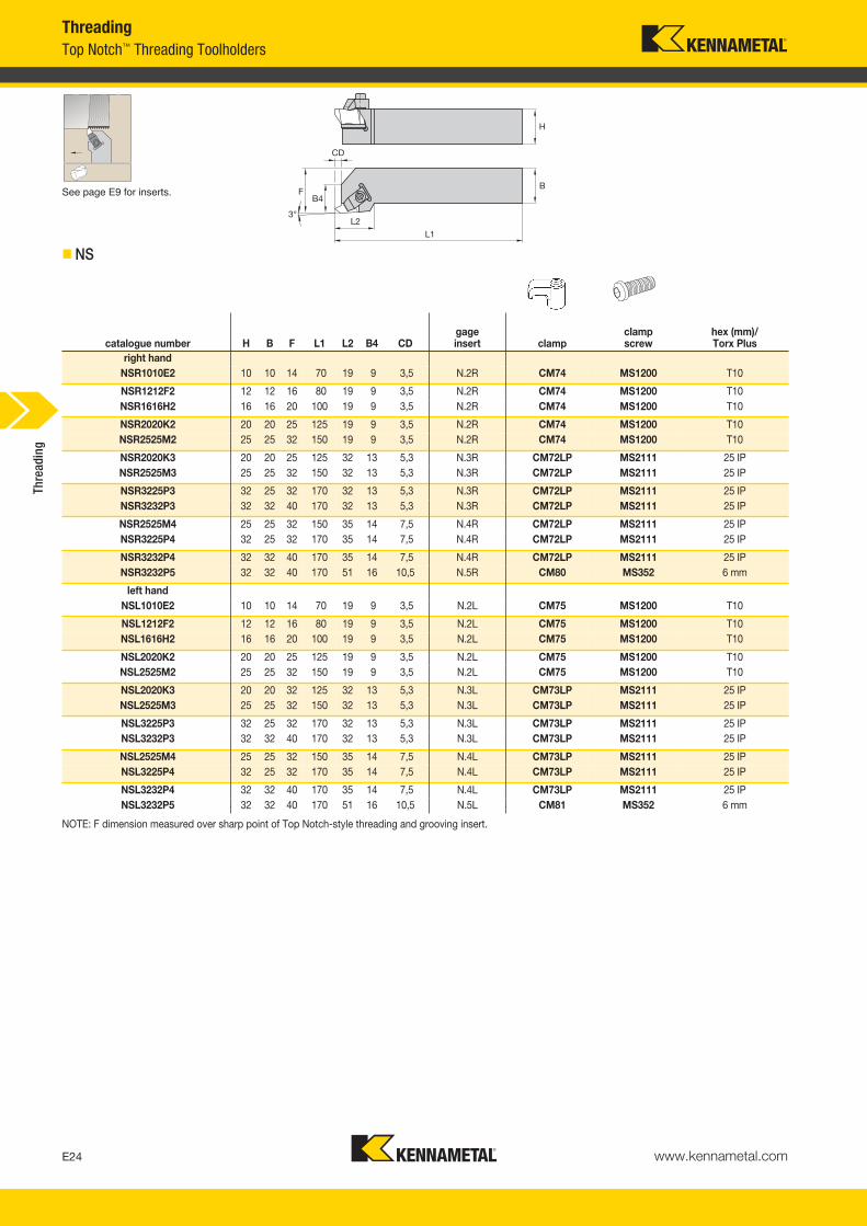
right handNSR1010E2 10 10 14 70 19 9 3,5 N.2R CM74 MS1200 T10
NSR1212F2 12 12 16 80 19 9 3,5 N.2R CM74 MS1200 T10NSR1616H2 16 16 20 100 19 9 3,5 N.2R CM74 MS1200 T10
NSR2020K2 20 20 25 125 19 9 3,5 N.2R CM74 MS1200 T10NSR2525M2 25 25 32 150 19 9 3,5 N.2R CM74 MS1200 T10
NSR2020K3 20 20 25 125 32 13 5,3 N.3R CM72LP MS2111 25 IPNSR2525M3 25 25 32 150 32 13 5,3 N.3R CM72LP MS2111 25 IP
NSR3225P3 32 25 32 170 32 13 5,3 N.3R CM72LP MS2111 25 IPNSR3232P3 32 32 40 170 32 13 5,3 N.3R CM72LP MS2111 25 IP
NSR2525M4 25 25 32 150 35 14 7,5 N.4R CM72LP MS2111 25 IPNSR3225P4 32 25 32 170 35 14 7,5 N.4R CM72LP MS2111 25 IP
NSR3232P4 32 32 40 170 35 14 7,5 N.4R CM72LP MS2111 25 IPNSR3232P5 32 32 40 170 51 16 10,5 N.5R CM80 MS352 6 mm
left handNSL1010E2 10 10 14 70 19 9 3,5 N.2L CM75 MS1200 T10
NSL1212F2 12 12 16 80 19 9 3,5 N.2L CM75 MS1200 T10NSL1616H2 16 16 20 100 19 9 3,5 N.2L CM75 MS1200 T10
NSL2020K2 20 20 25 125 19 9 3,5 N.2L CM75 MS1200 T10NSL2525M2 25 25 32 150 19 9 3,5 N.2L CM75 MS1200 T10
NSL2020K3 20 20 32 125 32 13 5,3 N.3L CM73LP MS2111 25 IPNSL2525M3 25 25 32 150 32 13 5,3 N.3L CM73LP MS2111 25 IP
NSL3225P3 32 25 32 170 32 13 5,3 N.3L CM73LP MS2111 25 IPNSL3232P3 32 32 40 170 32 13 5,3 N.3L CM73LP MS2111 25 IP
NSL2525M4 25 25 32 150 35 14 7,5 N.4L CM73LP MS2111 25 IPNSL3225P4 32 25 32 170 35 14 7,5 N.4L CM73LP MS2111 25 IP
NSL3232P4 32 32 40 170 35 14 7,5 N.4L CM73LP MS2111 25 IPNSL3232P5 32 32 40 170 51 16 10,5 N.5L CM81 MS352 6 mm
See page E9 for inserts.
� NS
NOTE: F dimension measured over sharp point of Top Notch-style threading and grooving insert.
ThreadingTop Notch™ Threading Toolholders
Thre
adin
g
KM_Master12_Turning_E024_E025_Metric.qxp:Layout 1 3/6/12 2:10 PM Page E24
www.kennametal.com E25
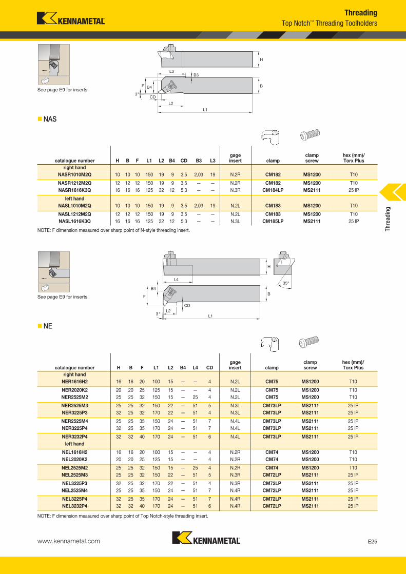
See page E9 for inserts.
� NAS
ThreadingTop Notch™ Threading Toolholders
catalogue number H B F L1 L2 B4 CD B3 L3gageinsert clamp
clampscrew
hex (mm)/Torx Plus
right handNASR1010M2Q 10 10 10 150 19 9 3,5 2,03 19 N.2R CM182 MS1200 T10
NASR1212M2Q 12 12 12 150 19 9 3,5 — — N.2R CM182 MS1200 T10NASR1616K3Q 16 16 16 125 32 12 5,3 — — N.3R CM184LP MS2111 25 IP
left handNASL1010M2Q 10 10 10 150 19 9 3,5 2,03 19 N.2L CM183 MS1200 T10
NASL1212M2Q 12 12 12 150 19 9 3,5 — — N.2L CM183 MS1200 T10NASL1616K3Q 16 16 16 125 32 12 5,3 — — N.3L CM185LP MS2111 25 IP
See page E9 for inserts.
� NE
NOTE: F dimension measured over sharp point of Top Notch-style threading insert.
catalogue number H B F L1 L2 B4 L4 CDgageinsert clamp
clampscrew
hex (mm)/Torx Plus
right handNER1616H2 16 16 20 100 15 — — 4 N.2L CM75 MS1200 T10
NER2020K2 20 20 25 125 15 — — 4 N.2L CM75 MS1200 T10NER2525M2 25 25 32 150 15 — 25 4 N.2L CM75 MS1200 T10
NER2525M3 25 25 32 150 22 — 51 5 N.3L CM73LP MS2111 25 IPNER3225P3 32 25 32 170 22 — 51 4 N.3L CM73LP MS2111 25 IP
NER2525M4 25 25 35 150 24 — 51 7 N.4L CM73LP MS2111 25 IPNER3225P4 32 25 35 170 24 — 51 7 N.4L CM73LP MS2111 25 IP
NER3232P4 32 32 40 170 24 — 51 6 N.4L CM73LP MS2111 25 IPleft hand
NEL1616H2 16 16 20 100 15 — — 4 N.2R CM74 MS1200 T10NEL2020K2 20 20 25 125 15 — — 4 N.2R CM74 MS1200 T10
NEL2525M2 25 25 32 150 15 — 25 4 N.2R CM74 MS1200 T10NEL2525M3 25 25 32 150 22 — 51 5 N.3R CM72LP MS2111 25 IP
NEL3225P3 32 25 32 170 22 — 51 4 N.3R CM72LP MS2111 25 IPNEL2525M4 25 25 35 150 24 — 51 7 N.4R CM72LP MS2111 25 IP
NEL3225P4 32 25 35 170 24 — 51 7 N.4R CM72LP MS2111 25 IPNEL3232P4 32 32 40 170 24 — 51 6 N.4R CM72LP MS2111 25 IP
Thre
adin
g
NOTE: F dimension measured over sharp point of N-style threading insert.
KM_Master12_Turning_E024_E025_Metric.qxp:Layout 1 3/6/12 2:10 PM Page E25

www.kennametal.comE26
*Kennametal standard only.
A
A25RNNTOR2
25 R NBar
TypeBar
DiameterBar
LengthInsert
Holding Method
metric bars:
M = 150mm
Q = 180mm
R = 200mm
S = 250mm
T = 300mm
U = 350mm
N* = Top NotchA = Steel with coolant
E = Carbide with coolant
H = Interchangeable head
Top Notch™ Boring Bar Catalogue Numbering SystemThreading
Bar diameter in millimetres
A Dia. E
E
H
How Do Catalogue Numbers Work?Each character in our catalogue number signifies a specific trait of thatproduct. Use the following key columns and corresponding imagesto easily identify which attributes apply.
Thre
adin
g
KM_Master12_Turning_E026_E027_Metric.qxp:Layout 1 3/27/12 10:33 AM Page E26
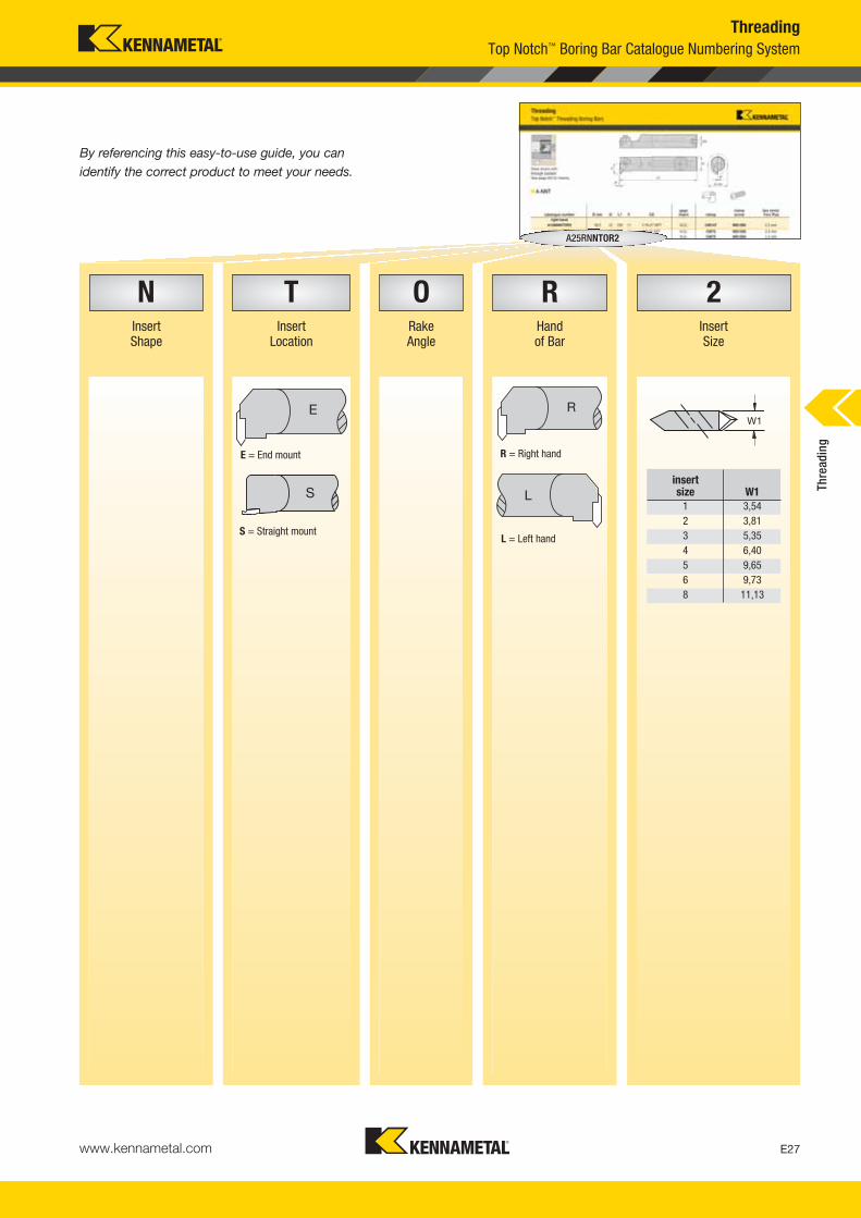
www.kennametal.com E27
InsertShape
InsertLocation
RakeAngle
Handof Bar
InsertSize
A25RNNTOR2
ThreadingTop Notch™ Boring Bar Catalogue Numbering System
insert size W1
1 3,542 3,813 5,354 6,405 9,656 9,738 11,13
S = Straight mount
R = Right hand
L = Left hand
W1R
L
E
S
E = End mount
N T O R 2
Thre
adin
g
By referencing this easy-to-use guide, you canidentify the correct product to meet your needs.
KM_Master12_Turning_E026_E027_Metric.qxp:Layout 1 3/27/12 10:33 AM Page E27
www.kennametal.comE28
D min
catalogue number D min D L1 F CSgageinsert clamp
clampscrew
hex (mm)/Torx Plus
right handA12MNNTOR2 18,5 12 150 11 1/16-27 NPT N.2L CM147 MS1200 2.5 mm
A16MNNTOR2 22,0 16 150 11 1/8-27 NPT N.2L CM75 MS1200 2.5 mmA20QNNTOR2 26,0 20 180 13 1/8-27 NPT N.2L CM75 MS1200 2.5 mm
A25RNNTOR2 34,0 25 200 17 1/4-18 NPT N.2L CM75 MS1200 2.5 mmA25RNNTOR3 34,0 25 200 17 1/4-18 NPT N.3L CM73LP MS2111 25 IP
A32SNNTOR3 44,0 32 250 22 1/4-18 NPT N.3L CM73LP MS2111 25 IPA40TNNTOR3 54,0 40 300 27 1/4-18 NPT N.3L CM73LP MS2111 25 IP
A40TNNTOR4 54,0 40 300 27 1/4-18 NPT N.4L CM73LP MS2111 25 IPA50UNNTOR4 70,0 50 350 35 1/4-18 NPT N.4L CM73LP MS2111 25 IP
left handA12MNNTOL2 18,5 12 150 11 1/16-27 NPT N.2R CM146 MS1200 2.5 mm
A16MNNTOL2 22,0 16 150 11 1/8-27 NPT N.2R CM74 MS1200 2.5 mmA20QNNTOL2 26,0 20 180 13 1/8-27 NPT N.2R CM74 MS1200 2.5 mm
A25RNNTOL2 34,0 25 200 17 1/4-18 NPT N.2R CM74 MS1200 2.5 mmA25RNNTOL3 34,0 25 200 17 1/4-18 NPT N.3R CM72LP MS2111 25 IP
A32SNNTOL3 44,0 32 250 22 1/4-18 NPT N.3R CM72LP MS2111 25 IPA40TNNTOL3 54,0 40 300 27 1/4-18 NPT N.3R CM72LP MS2111 25 IP
A40TNNTOL4 54,0 40 300 27 1/4-18 NPT N.4R CM72LP MS2111 25 IPA50UNNTOL4 70,0 50 350 35 1/4-18 NPT N.4R CM72LP MS2111 25 IP
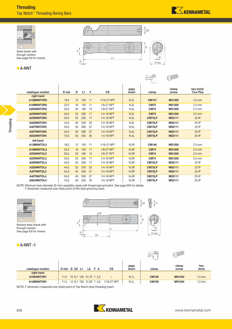
Steel shank with through coolant.See page E9 for inserts.
� A-NNT
NOTE: Minimum bore diameter (D min) capability varies with thread type and pitch. See page E93 for details. F dimension measured over sharp point of NG-style grooving insert.
catalogue number D min D D2 L1 L2 F A CSgageinsert clamp
clampscrew
hex(mm)
right handA10KNNTOR1 11,5 10 8,7 125 31,75 7 3,2 — N.1L CM109 MS1034 1.5 mm
A12MNNTOR1 11,5 12 8,7 150 31,30 7 4,0 1/16-27 NPT N.1L CM109 MS1034 1.5 mm
Necked steel shank with through coolant.See page E9 for inserts.
� A-NNT -1
NOTE: F dimension measured over sharp point of Top Notch-style threading insert.
ThreadingTop Notch™ Threading Boring Bars
Thre
adin
g
KM_Master12_Turning_E028_E029_Metric.qxp:Layout 1 3/6/12 2:11 PM Page E28
www.kennametal.com E29
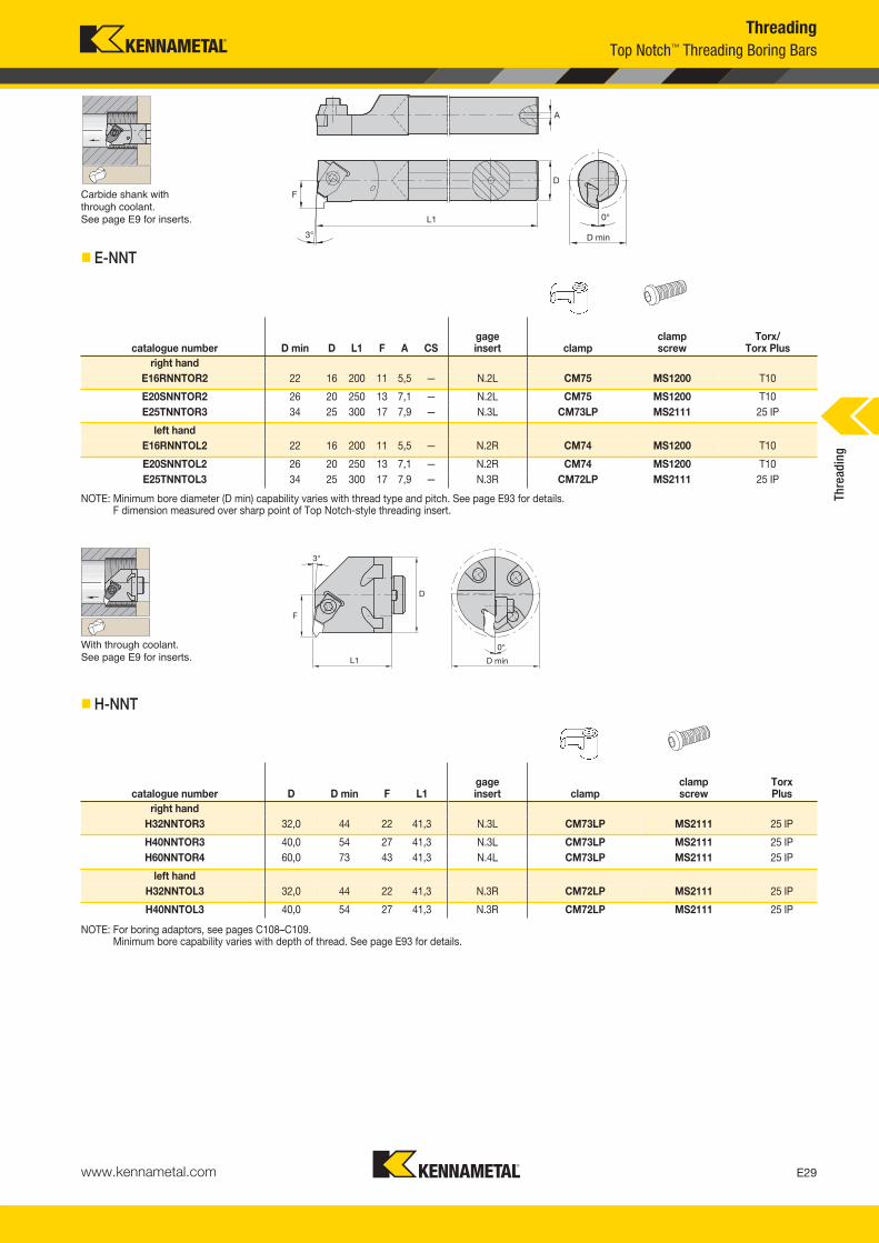
D min
Carbide shank with through coolant.See page E9 for inserts.
� E-NNT
NOTE: Minimum bore diameter (D min) capability varies with thread type and pitch. See page E93 for details.F dimension measured over sharp point of Top Notch-style threading insert.
3°
F
0°
L1
D
D min
With through coolant.See page E9 for inserts.
� H-NNT
NOTE: For boring adaptors, see pages C108–C109.Minimum bore capability varies with depth of thread. See page E93 for details.
ThreadingTop Notch™ Threading Boring Bars
catalogue number D min D L1 F A CSgageinsert clamp
clampscrew
Torx/Torx Plus
right handE16RNNTOR2 22 16 200 11 5,5 — N.2L CM75 MS1200 T10
E20SNNTOR2 26 20 250 13 7,1 — N.2L CM75 MS1200 T10E25TNNTOR3 34 25 300 17 7,9 — N.3L CM73LP MS2111 25 IP
left handE16RNNTOL2 22 16 200 11 5,5 — N.2R CM74 MS1200 T10
E20SNNTOL2 26 20 250 13 7,1 — N.2R CM74 MS1200 T10E25TNNTOL3 34 25 300 17 7,9 — N.3R CM72LP MS2111 25 IP
Thre
adin
g
catalogue number D D min F L1gageinsert clamp
clampscrew
TorxPlus
right handH32NNTOR3 32,0 44 22 41,3 N.3L CM73LP MS2111 25 IP
H40NNTOR3 40,0 54 27 41,3 N.3L CM73LP MS2111 25 IPH60NNTOR4 60,0 73 43 41,3 N.4L CM73LP MS2111 25 IP
left handH32NNTOL3 32,0 44 22 41,3 N.3R CM72LP MS2111 25 IP
H40NNTOL3 40,0 54 27 41,3 N.3R CM72LP MS2111 25 IP
KM_Master12_Turning_E028_E029_Metric.qxp:Layout 1 3/6/12 2:11 PM Page E29
www.kennametal.comE30
Thre
adin
g
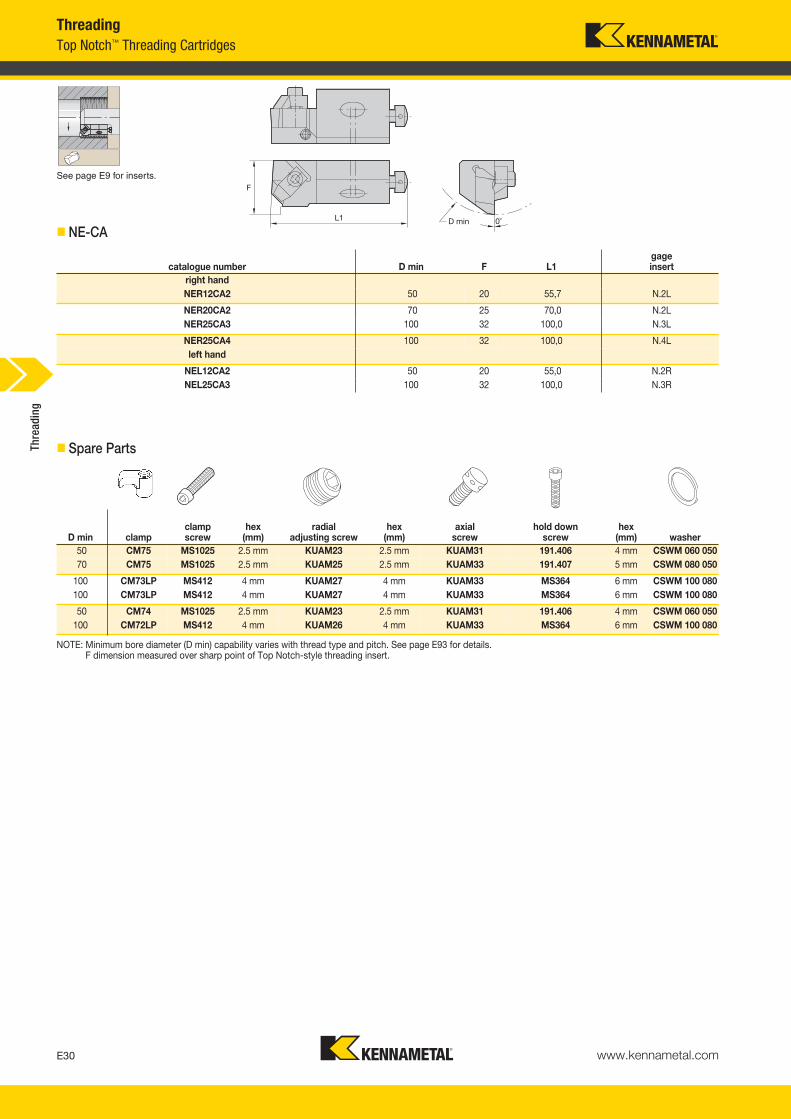
See page E9 for inserts.
� NE-CA
� Spare Parts
NOTE: Minimum bore diameter (D min) capability varies with thread type and pitch. See page E93 for details.F dimension measured over sharp point of Top Notch-style threading insert.
ThreadingTop Notch™ Threading Cartridges
catalogue number D min F L1gageinsert
right handNER12CA2 50 20 55,7 N.2L
NER20CA2 70 25 70,0 N.2LNER25CA3 100 32 100,0 N.3L
NER25CA4 100 32 100,0 N.4Lleft hand
NEL12CA2 50 20 55,0 N.2RNEL25CA3 100 32 100,0 N.3R
D min clampclampscrew
hex(mm)
radial adjusting screw
hex(mm)
axial screw
hold down screw
hex(mm) washer
50 CM75 MS1025 2.5 mm KUAM23 2.5 mm KUAM31 191.406 4 mm CSWM 060 05070 CM75 MS1025 2.5 mm KUAM25 2.5 mm KUAM33 191.407 5 mm CSWM 080 050
100 CM73LP MS412 4 mm KUAM27 4 mm KUAM33 MS364 6 mm CSWM 100 080100 CM73LP MS412 4 mm KUAM27 4 mm KUAM33 MS364 6 mm CSWM 100 080
50 CM74 MS1025 2.5 mm KUAM23 2.5 mm KUAM31 191.406 4 mm CSWM 060 050100 CM72LP MS412 4 mm KUAM26 4 mm KUAM33 MS364 6 mm CSWM 100 080
KM_Master12_Turning_E030_E031_Metric.qxp:Layout 1 3/27/12 10:37 AM Page E30
www.kennametal.com E31
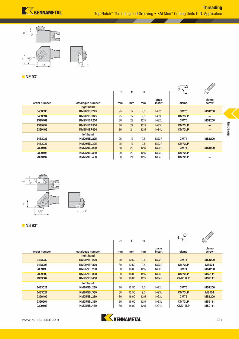
L1 F H1
order number catalogue number mm mm mmgageinsert clamp
clampscrew
right hand3483036 KM20NER225 25 17 9,5 NG2L CM75 MS1200
3483034 KM20NER325 25 17 9,5 NG3L CM73LP —2399462 KM25NER230 30 22 12,5 NG2L CM75 MS1200
2399494 KM25NER330 30 22 12,5 NG3L CM73LP —2399496 KM25NER430 30 24 12,5 NG4L CM73LP —
left hand3483035 KM20NEL225 25 17 9,5 NG2R CM74 MS1200
3483033 KM20NEL325 25 17 9,5 NG3R CM72LP —2399493 KM25NEL230 30 22 12,5 NG2R CM74 MS1200
2399495 KM25NEL330 30 22 12,5 NG3R CM72LP —2399497 KM25NEL430 30 24 12,5 NG4R CM72LP —
ThreadingTop Notch™ Threading and Grooving • KM Mini™ Cutting Units O.D. Application
� NE 93°
L1 F H1
order number catalogue number mm mm mmgageinsert clamp
clampscrew
right hand3483030 KM20NSR230 30 12,50 9,5 NG2R CM74 MS1200
3483028 KM20NSR330 30 12,50 9,5 NG3R CM72LP MS5242399498 KM25NSR230 30 16,00 12,5 NG2R CM74 MS1200
2399500 KM25NSR330 30 16,00 12,5 NG3R CM72LP MS21112399502 KM25NSR430 30 16,00 12,5 NG4R CM212LP MS2111
left hand3483029 KM20NSL230 30 12,50 9,5 NG2L CM75 MS1200
3483027 KM20NSL330 30 12,50 9,5 NG3L CM73LP MS5242399499 KM25NSL230 30 16,00 12,5 NG2L CM75 MS1200
2399501 KM25NSL330 30 16,00 12,5 NG3L CM73LP MS21112399503 KM25NSL430 30 16,00 12,5 NG4L CM213LP MS2111
� NS 93°Th
read
ing
KM_Master12_Turning_E030_E031_Metric.qxp:Layout 1 3/27/12 10:37 AM Page E31

www.kennametal.comE32
Thre
adin
g
L1 F D min
order number catalogue number mm mm mmgageinsert clamp
clampscrew kg
right hand3902285 KM40TSNER2 40 27 54 NG2L CM75 MS1488 0,31
3902286 KM40TSNER3 40 27 54 NG3L CM73 MS1489 0,303902287 KM40TSNER4 40 27 54 NG4L CM73 MS1489 0,30
left hand3902132 KM40TSNEL2 40 27 54 NG2R CM74 MS1488 0,31
3902283 KM40TSNEL3 40 27 54 NG3R CM72 MS1489 0,313902284 KM40TSNEL4 40 27 54 NG4R CM72 MS1489 0,30
ThreadingTop Notch™ Threading and Grooving • KM40TS™ Cutting Units
� NE 93°
KM_Master12_Turning_E032_E033_Metric.qxp:Layout 1 3/6/12 2:11 PM Page E32

www.kennametal.com E33
L1 F
order number catalogue number mm mmgageinsert clamp
clampscrew kg
right hand3902293 KM40TSNSR2 40 27 NG2R CM74 MS1488 0,32
3902294 KM40TSNSR3 47 27 NG3R CM72 MS1489 0,323902295 KM40TSNSR4 47 27 NG4R CM72 MS1489 0,31
left hand3902290 KM40TSNSL2 40 27 NG2L CM75 MS1488 0,32
3902291 KM40TSNSL3 47 27 NG3L CM73 MS1489 0,333902292 KM40TSNSL4 47 27 NG4L CM73 MS1489 0,31
� NS 93°
ThreadingTop Notch™ Threading and Grooving • KM40TS™ Cutting Units
Thre
adin
g
KM_Master12_Turning_E032_E033_Metric.qxp:Layout 1 3/6/12 2:11 PM Page E33
www.kennametal.comE34
Thre
adin
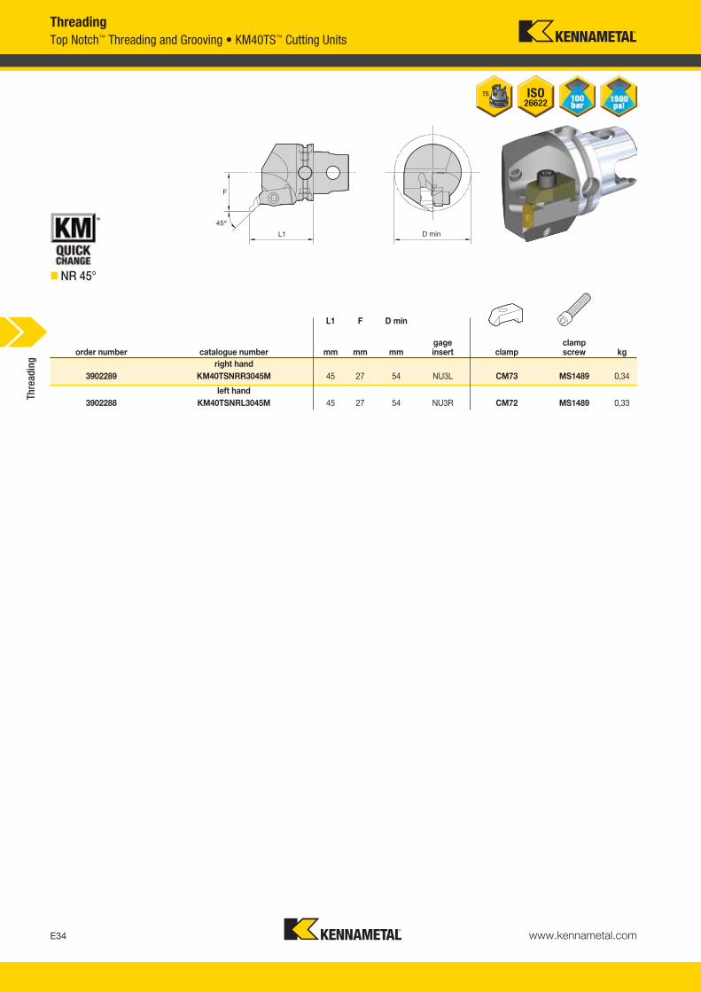
gThreadingTop Notch™ Threading and Grooving • KM40TS™ Cutting Units
� NR 45°
L1 F D min
order number catalogue number mm mm mmgageinsert clamp
clampscrew kg
right hand3902289 KM40TSNRR3045M 45 27 54 NU3L CM73 MS1489 0,34
left hand3902288 KM40TSNRL3045M 45 27 54 NU3R CM72 MS1489 0,33
KM_Master12_Turning_E034_E035_Metric.qxp:Layout 1 3/6/12 2:11 PM Page E34
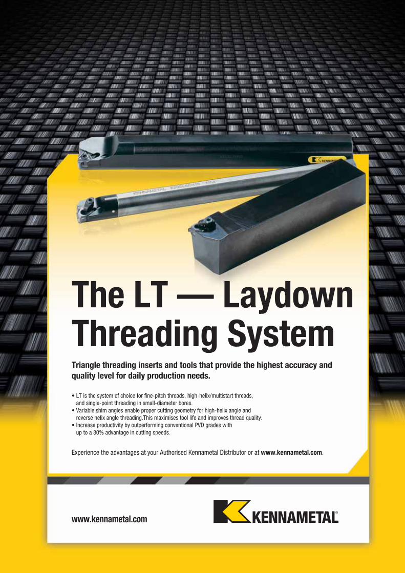
Experience the advantages at your Authorised Kennametal Distributor or at www.kennametal.com.
www.kennametal.com
The LT — LaydownThreading SystemTriangle threading inserts and tools that provide the highest accuracy andquality level for daily production needs.
• LT is the system of choice for fine-pitch threads, high-helix/multistart threads, and single-point threading in small-diameter bores.
• Variable shim angles enable proper cutting geometry for high-helix angle and reverse helix angle threading.This maximises tool life and improves thread quality.
• Increase productivity by outperforming conventional PVD grades with up to a 30% advantage in cutting speeds.
KM_Master12_Turning_E034_E035_Metric.qxp:Layout 1 3/6/12 2:11 PM Page E35
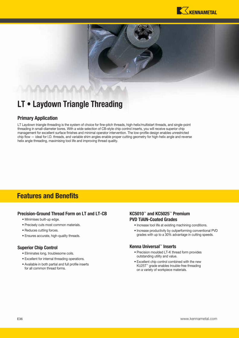
Primary ApplicationLT Laydown triangle threading is the system of choice for fine-pitch threads, high-helix/multistart threads, and single-pointthreading in small-diameter bores. With a wide selection of CB-style chip control inserts, you will receive superior chip management for excellent surface finishes and minimal operator intervention. The low-profile design enables unrestrictedchip flow — ideal for I.D. threads, and variable shim angles enable proper cutting geometry for high-helix angle and reversehelix angle threading, maximising tool life and improving thread quality.
Precision-Ground Thread Form on LT and LT-CB• Minimises built-up edge.
• Precisely cuts most common materials.
• Reduces cutting forces.
• Ensures accurate, high-quality threads.
Superior Chip Control • Eliminates long, troublesome coils.
• Excellent for internal threading operations.
• Available in both partial and full profile inserts for all common thread forms.
KC5010™ and KC5025™ Premium PVD TiAlN-Coated Grades
• Increase tool life at existing machining conditions.
• Increase productivity by outperforming conventional PVD grades with up to a 30% advantage in cutting speeds.
Kenna Universal™ Inserts• Precision moulded LT-K thread form provides
outstanding utility and value.
• Excellent chip control combined with the new KU25T™ grade enables trouble-free threading on a variety of workpiece materials.
Features and Benefits
LT • Laydown Triangle Threading
www.kennametal.comE36
KM_Master12_Turning_E036_E037_Metric.qxp:Layout 1 3/6/12 2:12 PM Page E36
www.kennametal.com E37
KM_Master12_Turning_E036_E037_Metric.qxp:Layout 1 3/6/12 2:12 PM Page E37
www.kennametal.comE38
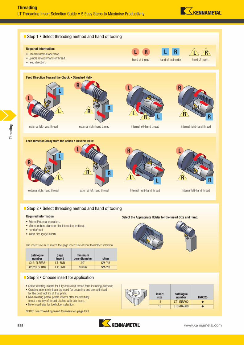
� Step 1 • Select threading method and hand of tooling
LT Threading Insert Selection Guide • 5 Easy Steps to Maximise ProductivityThreading
hand of thread hand of toolholder hand of insert
RLRL L R
L
R
L
R
L
R
L
R
L R
L R
L R
LR
external left-hand thread external right-hand thread internal left-hand thread internal right-hand thread
external right-hand thread external left-hand thread internal right-hand thread internal left-hand thread
R
R
R R
R
L
L
L
L
The insert size must match the gage insert size of your toolholder selection:
Required Information:
• External/internal operation.• Minimum bore diameter (for internal operations).• Hand of tool.• Insert size (gage insert).
Select the Appropriate Holder for the Insert Size and Hand:
cataloguenumber
gageinsert
minimumbore diameter shim
S1212LSER3 LT16NR .90" SM-YI3A2020LSER16 LT16NR 16mm SM-YI3
• Select cresting inserts for fully controlled thread form including diameter.• Cresting inserts eliminate the need for deburring and are optimised
for the best tool life at that pitch.• Non-cresting partial profile inserts offer the flexibility
to cut a variety of thread pitches with one insert.• Note insert size for toolholder selection.
NOTE: See Threading Insert Overview on page E41.
insert size
cataloguenumber TN6025
11 LT11NRA60 �
16 LT6NRAG60 �
� Step 3 • Choose insert for application
� Step 2 • Select threading method and hand of tooling
Feed Direction Away from the Chuck • Reverse Helix
Feed Direction Toward the Chuck • Standard Helix
Required Information:
• External/internal operation.• Spindle rotation/hand of thread.• Feed direction.
Thre
adin
g
KM_Master12_Turning_E038_E039_Metric.qxp:Layout 1 3/6/12 2:12 PM Page E38
www.kennametal.com E39
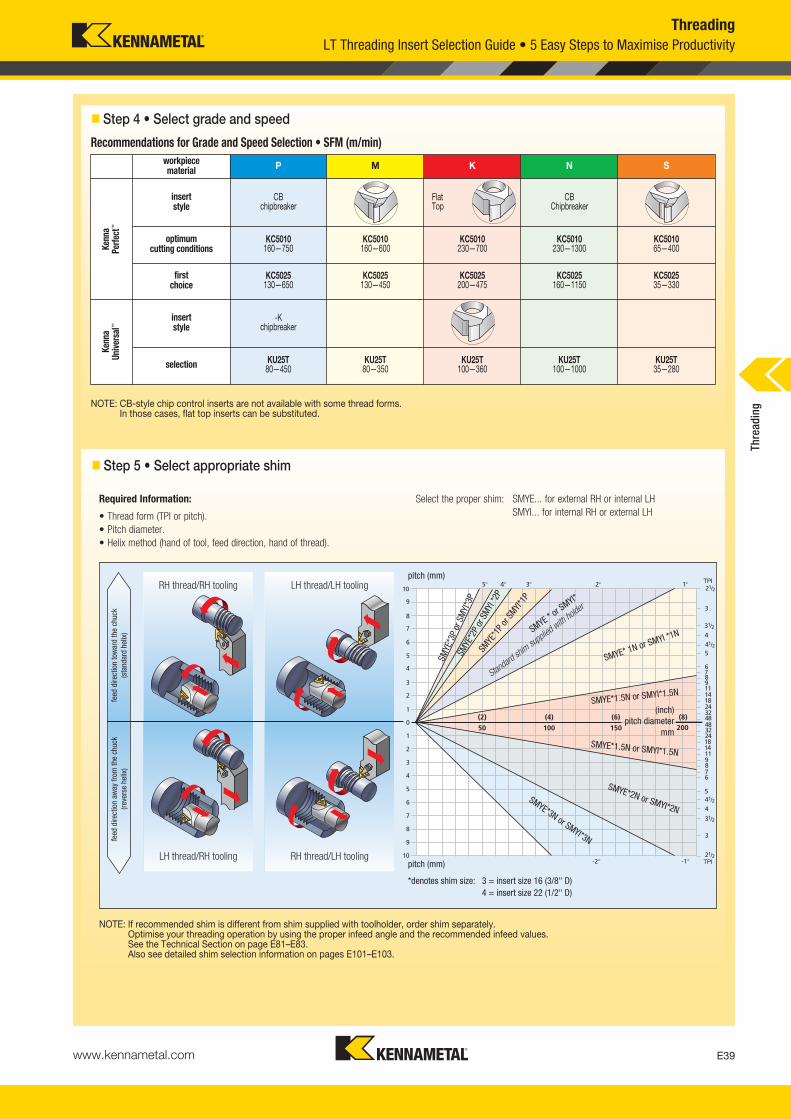
ThreadingLT Threading Insert Selection Guide • 5 Easy Steps to Maximise Productivity
� Step 5 • Select appropriate shim
RH thread/RH tooling LH thread/LH tooling
LH thread/RH tooling RH thread/LH tooling
Required Information:
• Thread form (TPI or pitch).• Pitch diameter.• Helix method (hand of tool, feed direction, hand of thread).
Select the proper shim: SMYE... for external RH or internal LHSMYI... for internal RH or external LH
NOTE: If recommended shim is different from shim supplied with toolholder, order shim separately.Optimise your threading operation by using the proper infeed angle and the recommended infeed values. See the Technical Section on page E81–E83.Also see detailed shim selection information on pages E101–E103.
TPI
TPI
pitch (mm)
SMYE
*3P
or S
MYI
*3P
SMYE
*1P o
r SMYI*
1P
SMYE * or S
MYI*
Standar
d shim
suppl
ied with
holder
SMYE* 1N or SMYI *1N
SMYE*1.5N or SMYI*1.5N
(inch)pitch diameter
mm
SMYE*2N or SMYI*2NSMYE*3N or SMYI*3N
SMYE*1.5N or SMYI*1.5N
SMYE
*2P
or S
MYI
*2P
pitch (mm)
*denotes shim size: 3 = insert size 16 (3/8" D)4 = insert size 22 (1/2" D)
feed
dire
ctio
n to
war
d th
e ch
uck
(sta
ndar
dhe
lix)
feed
dire
ctio
n aw
ay fr
om th
e ch
uck
(reve
rse
helix
)� Step 4 • Select grade and speed
NOTE: CB-style chip control inserts are not available with some thread forms. In those cases, flat top inserts can be substituted.
Recommendations for Grade and Speed Selection • SFM (m/min)workpiecematerial P M K N S
Kenn
aPe
rfect
™
insert style
CBchipbreaker
Flat Top
CB Chipbreaker
optimum cutting conditions
KC5010160—750
KC5010160—600
KC5010230—700
KC5010230—1300
KC501065—400
first choice
KC5025130—650
KC5025130—450
KC5025200—475
KC5025160—1150
KC502535—330
Kenn
aUn
iver
sal™
insert style
-Kchipbreaker
selection KU25T80—450
KU25T80—350
KU25T100—360
KU25T100—1000
KU25T35—280
Thre
adin
g
KM_Master12_Turning_E038_E039_Metric.qxp:Layout 1 3/6/12 2:12 PM Page E39
www.kennametal.comE40
LT
LT16ERAG20UNCB
16 ER AG20Type ofInsert
Cutting EdgeLength (Size)
Hand ofInsert
Thread Pitch
UN CBThread Profile
ChipControl
How Do Catalogue Numbers Work?Each character in our catalogue number signifies a specific trait of thatproduct. Use the following key columns and corresponding imagesto easily identify which attributes apply.
LT Threading Catalogue Numbering SystemThreading
ISO = ISO metric 60°UN = American UN 60°60 = Partial profile non-cresting 60°55 = Partial profile non-cresting 55°W = Whitworth 55°
BSPT = British Standard Pipe Thread 55°
NPT = American National Pipe Thread 60°
ACME = American AcmeSTACME = American Stub Acme
TR = Trapez DIN 103RD = Round DIN 405
UNJ = Controlled root radius 60°NPTF = Dryseal 60°
API = American Petroleum InstituteThreads
BUT = API Buttress CasingAPIRD = API Round
partial profiledesignation thread pitch (mm) TPI
A 0,50–1,5 48–16AG 0,50–3,0 48–8G 1,75–3,0 14–8N 3,50–5,0 7–5
full profile
actual TPI or pitch in mm is designated 0,5–4,0 48–8
The Kennametal LT AdvantageEvery box of 10 inserts includes a freeTorx wrench and spare locking screw, except LT-K inserts.
ER = External right hand
EL = External left hand
NR = Internal right hand
NL = Internal left hand
□ = Flat top
CB = ChipbreakerK = Kenna
Universal™
chipbreaker
LT = Laydowntrianglethreading
insert size
LI(mm)
D(mm)
11 11,0 6,3516 16,5 9,5222 22,0 12,70
S(mm)
D1(mm)
3,20 3,253,63 3,944,78 4,88
Thre
adin
g
KM_Master12_Turning_E040_E041_Metric.qxp:Layout 1 3/6/12 2:12 PM Page E40

www.kennametal.com E41
LT Threading • Insert OverviewThreading
style
thread profile standard
tolerance class cresting application page(s)CB K flat top
Partial Profile 60° — — N
General use for 60° thread forms such as ISO and UNwhere non-cresting inserts are desired to cut a variety
of pitches E42
LT-60CB LT-60K LT-60
Metric ISO ISO R262,DIN 13 6g / 6H Y
Widely used metric 60° V-form for all industries
E44–E47
LT-ISOCB LT-ISOK LT-ISO
American UN ANSI B1.1:74 2A / 2B Y
Widely used inch-based 60° V-form for all industries
E48–E49
LT-UNCB LT-UN
UNJ MIL-S-8879C 3A / 3B Y
Controlled root radius on external threads for military and aerospace industries, 60° thread form
E50, E52
LT-UNK LT-UNJ
NPT USAS B2.1:1968 StandardNPT Y
National Pipe thread standard 60° thread form for pipe fittings
E53
LT-NPTCB LT-NPT
NPTF ANSI B1.20.3-1976 Class 2 Y
Dryseal-type NPT 60° thread form for pipe fittings
E54
LT- NPTFCB LT-NPTF
Partial Profile 55° — — N
General use for 55° thread forms such as Whitworth,BSW, and BSP where non-cresting inserts are desired
to cut a variety of pitches E55
LT-55K LT-55
BSPT BS 21:1985 StandardBSPT Y
55° form for pipe fittings
E59
LT-BSPT
NPT Whitworth, BSW, BSF, BSP
MediumClass A Y
Widely used 55° form for gas and water connections
E57–E58
LT-WCB LT-WK LT-W
NPT— multitooth API STD. 5B:1979 Standard
API Y
60° V-form used for rotary shoulder pipe connections inthe oil and gas industry including V-.038R, V-.040, and
V-.050 forms E59
LT-API
API Round API SPEC. 7:1990 StandardAPI RD
Y
60° V-form with large radius for casing, tubing, and line pipe in the oil and gas industry including
8 and 10 round forms E60–E61
LT-APIRD
API Buttress Casing API SPEC. 7:1990 Standard
APIY
45° buttress-style form used for pipe casing connectionsin the oil and gas industry
E60
LT-BUT
Acme ANSI B1.5:1988 3G N
29° truncated thread form for motion applications in a wide variety of industries
E62
LT-ACME
Stub Acme ANSI B1.8:1988 2G N
Shallow depth 29° truncated thread form for motionapplications in a wide variety of industries
E62
LT-STACME
Round DIN 405 7h / 7H Y
Round thread form for tube fittings in the chemical and food industries
E64
LT-RD
Trapez DIN 103 7e / 7H N
30° truncated metric thread form for motion applications
E63
LT-TR
Thre
adin
g
KM_Master12_Turning_E040_E041_Metric.qxp:Layout 1 3/6/12 2:12 PM Page E41

www.kennametal.comE42
Partial Profile 60° External
� first choice� alternate choice
� LT-ER-60CB
Partial Profile 55° External
� LT-ER-55K
� LT-ER-60K
� LT-ER/L-60
Thread Forms
LT-ER-60CB LT-ER-55K LT-ER-60K LT-ER/L-60
P � � �
M � � �
K � � �
N � � �
S � � �
H �
ThreadingLT Threading Inserts
RC EX E
catalogue numberinsertsize mm mm mm
thread pitch mm TPI K
C50
10K
C50
25K
U25
T
right handLT16ERAG60CB 16 0,08 0,9 1,5 0,50-3,0 48-8 � �
RC EX E
catalogue numberinsertsize mm mm mm
thread pitch mm TPI
right handLT16ERAG55K 16 0,07 1,2 1,7 0,50-3,0 48-8 �
RC EX E
catalogue numberinsertsize mm mm mm
thread pitch mm TPI
right handLT16ERAG60K 16 0,08 1,2 1,7 0,50-3,0 48-8 �
LT16ERG60K 16 0,18 1,2 1,7 1,75-3,0 14-8 �
RC EX E
catalogue numberinsertsize mm mm mm
thread pitch mm TPI
right handLT16ERA60 16 0,05 0,8 0,9 0,50-1,5 48-16 � �
LT16ERAG60 16 0,08 1,2 1,7 0,50-3,0 48-8 � �
LT16ERG60 16 0,28 1,2 1,7 1,75-3,0 14-8 � �
LT22ERN60 22 0,53 1,7 2,5 3,5-5,0 7-5 �
left hand
LT16ELA60 16 0,05 0,8 0,9 0,50-1,5 48-16 �
LT16ELAG60 16 0,08 1,2 1,7 0,50-3,0 48-8 �
LT16ELG60 16 0,28 1,2 1,7 1,75-3,0 14-8 �
LT22ELN60 22 0,53 1,7 2,5 3,5-5,0 7-5 �
Thre
adin
g
KM_Master12_Turning_E042_E043_Metric.qxp:Layout 1 3/6/12 2:12 PM Page E42
www.kennametal.com E43
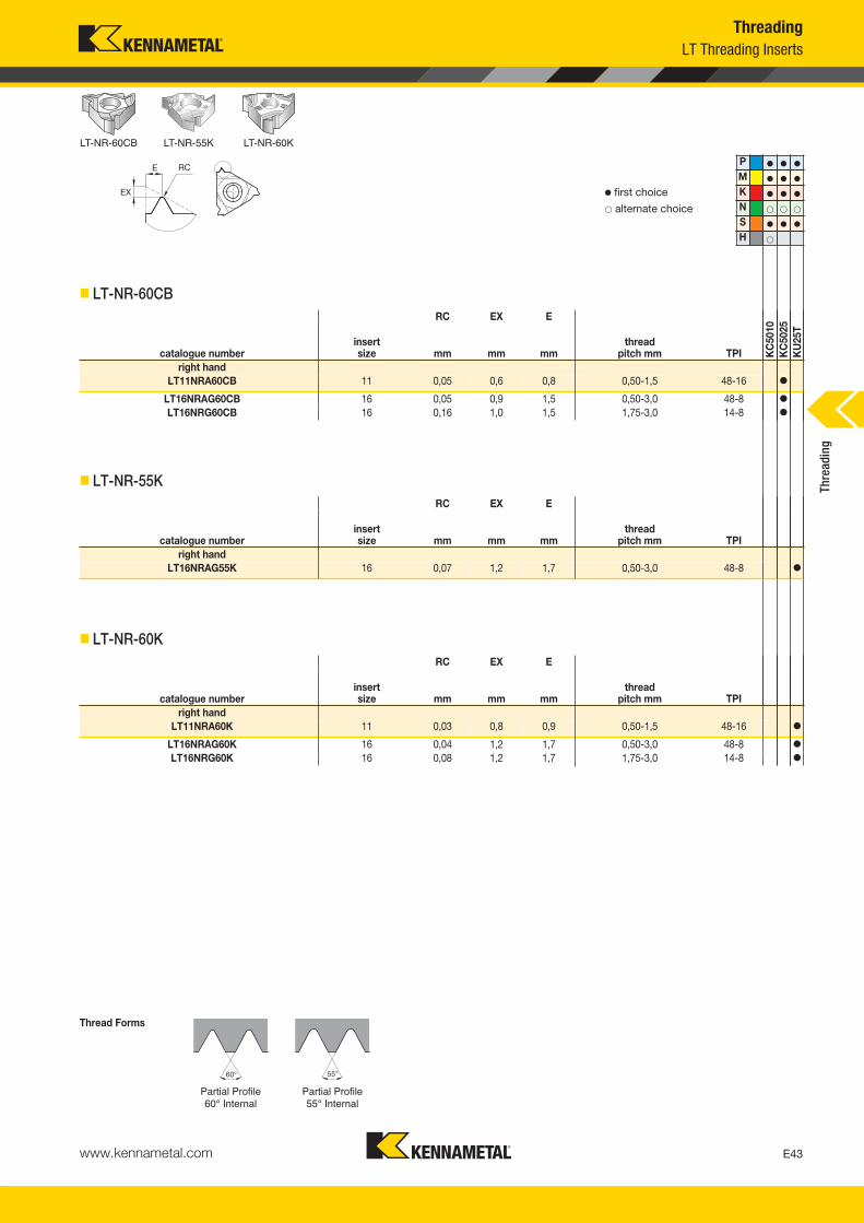
Partial Profile60° Internal
� first choice� alternate choice
� LT-NR-60CB
Partial Profile 55° Internal
� LT-NR-55K
� LT-NR-60K
Thread Forms
LT-NR-60CB LT-NR-55K LT-NR-60K
P � � �
M � � �
K � � �
N � � �
S � � �
H �
ThreadingLT Threading Inserts
RC EX E
catalogue numberinsertsize mm mm mm
thread pitch mm TPI K
C50
10K
C50
25K
U25
T
right handLT11NRA60CB 11 0,05 0,6 0,8 0,50-1,5 48-16 �
LT16NRAG60CB 16 0,05 0,9 1,5 0,50-3,0 48-8 �
LT16NRG60CB 16 0,16 1,0 1,5 1,75-3,0 14-8 �
RC EX E
catalogue numberinsertsize mm mm mm
thread pitch mm TPI
right handLT16NRAG55K 16 0,07 1,2 1,7 0,50-3,0 48-8 �
RC EX E
catalogue numberinsertsize mm mm mm
thread pitch mm TPI
right handLT11NRA60K 11 0,03 0,8 0,9 0,50-1,5 48-16 �
LT16NRAG60K 16 0,04 1,2 1,7 0,50-3,0 48-8 �
LT16NRG60K 16 0,08 1,2 1,7 1,75-3,0 14-8 �
Thre
adin
g
KM_Master12_Turning_E042_E043_Metric.qxp:Layout 1 3/6/12 2:12 PM Page E43

www.kennametal.comE44
Partial Profile 60° Internal
� first choice� alternate choice
� LT-NR/L-60
ISO Metric-External
� LT-ER-ISOCB
Thread Forms
LT-NR/L-60 LT-ER-ISOCB
P � � �
M � � �
K � � �
N � � �
S � � �
H �
ThreadingLT Threading Inserts
RC EX E
catalogue numberinsertsize mm mm mm
thread pitch mm TPI K
C50
10K
C50
25K
U25
T
right handLT11NRA60 11 0,05 0,8 0,9 0,50-1,5 48-16 � �
LT16NRA60 16 0,05 0,8 0,9 0,50-1,5 48-16 � �
LT16NRAG60 16 0,05 1,2 1,7 0,50-3,0 48-8 � �
LT16NRG60 16 0,15 1,2 1,7 1,75-3,0 14-8 � �
LT22NRN60 22 0,31 1,7 2,5 3,5-5,0 7-5 �
left handLT11NLA60 11 0,05 0,8 0,9 0,50-1,5 48-16 �
LT16NLA60 16 0,05 0,8 0,9 0,50-1,5 48-16 �
LT16NLAG60 16 0,05 1,2 1,7 0,50-3,0 48-8 �
LT16NLG60 16 0,15 1,2 1,7 1,75-3,0 14-8 �
LT22NLN60 22 0,31 1,7 2,5 3,5-5,0 7-5 �
RC EX E
catalogue numberinsertsize mm mm mm
thread pitch mm TPI
right handLT16ER05ISOCB 16 — 1,2 0,5 0,50 — � �
LT16ER075ISOCB 16 — 1,2 0,6 0,75 — � �
LT16ER10ISOCB 16 — 0,7 0,8 1,0 — � �
LT16ER125ISOCB 16 — 0,7 0,8 1,25 — � �
LT16ER15ISOCB 16 — 0,7 0,8 1,5 — � �
LT16ER175ISOCB 16 — 1,2 1,5 1,75 — � �
LT16ER20ISOCB 16 — 1,2 1,5 2,0 — � �
LT16ER25ISOCB 16 — 1,2 1,5 2,5 — �
LT16ER30ISOCB 16 — 1,3 1,5 3,0 — � �
Thre
adin
g
KM_Master12_Turning_E044_E045_Metric.qxp:Layout 1 3/6/12 2:12 PM Page E44

www.kennametal.com E45
ISO Metric-External
� first choice� alternate choice
� LT-ER-ISOK
� LT-ER/L-ISO
Thread Forms
LT-ER-ISOK LT-ER/L-ISO
P � � �
M � � �
K � � �
N � � �
S � � �
H �
ThreadingLT Threading Inserts
RC EX E
catalogue numberinsertsize mm mm mm
thread pitch mm TPI K
C50
10K
C50
25K
U25
T
right handLT16ER10ISOK 16 0,14 0,7 0,7 1,0 — �
LT16ER125ISOK 16 0,16 1,1 0,8 1,25 — �
LT16ER15ISOK 16 0,20 0,8 1,0 1,5 — �
LT16ER175ISOK 16 0,22 1,2 1,5 1,75 — �
LT16ER20ISOK 16 0,27 1,0 1,3 2,0 — �
LT16ER25ISOK 16 0,32 1,2 1,5 2,5 — �
LT16ER30ISOK 16 0,38 1,3 1,5 3,0 — �
RC EX E
catalogue numberinsertsize mm mm mm
thread pitch mm TPI
right handLT16ER05ISO 16 — 0,6 0,4 0,50 — �
LT16ER075ISO 16 — 0,6 0,6 0,75 — �
LT16ER10ISO 16 — 0,7 0,7 1,0 — � �
LT16ER125ISO 16 — 0,8 0,9 1,25 — � �
LT16ER15ISO 16 — 0,8 1,0 1,5 — � �
LT16ER175ISO 16 — 0,9 1,2 1,75 — � �
LT16ER20ISO 16 — 1,0 1,3 2,0 — � �
LT16ER25ISO 16 — 1,1 1,5 2,5 — � �
LT16ER30ISO 16 — 1,2 1,6 3,0 — � �
LT22ER35ISO 22 — 1,6 2,3 3,5 — �
LT22ER40ISO 22 — 1,6 2,3 4,0 — �
LT22ER45ISO 22 — 1,7 2,4 4,5 — �
LT22ER50ISO 22 — 1,7 2,5 5,0 — �
left handLT16EL05ISO 16 — 0,6 0,4 0,50 — �
LT16EL075ISO 16 — 0,6 0,6 0,75 — �
LT16EL10ISO 16 — 0,7 0,7 1,0 — �
LT16EL125ISO 16 — 0,8 0,9 1,25 — �
LT16EL15ISO 16 — 0,8 1,0 1,5 — � �
LT16EL175ISO 16 — 0,9 1,2 1,75 — �
LT16EL20ISO 16 — 1,0 1,3 2,0 — �
LT16EL25ISO 16 — 1,1 1,5 2,5 — �
LT16EL30ISO 16 — 1,2 1,6 3,0 — �
LT22EL35ISO 22 — 1,6 2,3 3,5 — �
Thre
adin
g
KM_Master12_Turning_E044_E045_Metric.qxp:Layout 1 3/6/12 2:12 PM Page E45

www.kennametal.comE46
ISO Metric-Internal
� first choice� alternate choice
� LT-NR-ISOCB
� LT-NR-ISOK
Thread Forms
LT-NR-ISOCB LT-NR-ISOK
P � � �
M � � �
K � � �
N � � �
S � � �
H �
ThreadingLT Threading Inserts
RC EX E
catalogue numberinsertsize mm mm mm
thread pitch mm TPI K
C50
10K
C50
25K
U25
T
right handLT11NR075ISOCB 11 — 1,194 0,500 0,75 — �
LT11NR10ISOCB 11 — 0,711 0,787 1,0 — �
LT16NR10ISOCB 16 — 0,711 0,787 1,0 — �
LT11NR125ISOCB 11 — 0,711 0,787 1,25 — �
LT11NR15ISOCB 11 — 0,711 0,787 1,5 — �
LT16NR15ISOCB 16 — 0,711 0,787 1,5 — �
LT16NR20ISOCB 16 — 1,100 1,499 2,0 — �
LT16NR25ISOCB 16 — 1,100 1,499 2,5 — �
RC EX E
catalogue numberinsertsize mm mm mm
thread pitch mm TPI
right handLT11NR10ISOK 11 0,06 0,7 0,8 1,0 — �
LT16NR10ISOK 16 0,05 0,7 0,7 1,0 — �
LT16NR15ISOK 16 0,08 0,8 1,0 1,5 — �
LT16NR175ISOK 16 0,10 1,2 1,5 1,75 — �
LT16NR20ISOK 16 0,10 1,0 1,3 2,0 — �
LT16NR25ISOK 16 0,14 1,2 1,5 2,5 — �
LT16NR30ISOK 16 0,17 1,3 1,5 3,0 — �
Thre
adin
g
KM_Master12_Turning_E046_E047_Metric.qxp:Layout 1 3/27/12 10:41 AM Page E46

www.kennametal.com E47
ISO Metric-Internal
� first choice� alternate choice
� LT-NR/L-ISO
Thread Forms
LT-NR-ISO
P � � �
M � � �
K � � �
N � � �
S � � �
H �
ThreadingLT Threading Inserts
RC EX E
catalogue numberinsertsize mm mm mm
thread pitch mm TPI K
C50
10K
C50
25K
U25
T
right handLT11NR05ISO 11 — 0,6 0,4 0,50 — �
LT16NR05ISO 16 — 0,6 0,4 0,50 — �
LT11NR075ISO 11 — 0,6 0,6 0,75 — �
LT16NR075ISO 16 — 0,6 0,6 0,75 — �
LT11NR10ISO 11 — 0,6 0,7 1,0 — �
LT16NR10ISO 16 — 0,6 0,7 1,0 — � �
LT11NR125ISO 11 — 0,8 0,9 1,25 — �
LT16NR125ISO 16 — 0,8 0,9 1,25 — �
LT11NR15ISO 11 — 0,8 1,0 1,5 — � �
LT16NR15ISO 16 — 0,8 1,0 1,5 — � �
LT11NR175ISO 11 — 0,9 1,1 1,75 — �
LT16NR175ISO 16 — 0,9 1,2 1,75 — �
LT11NR20ISO 11 — 0,9 1,1 2,0 — �
LT16NR20ISO 16 — 1,0 1,3 2,0 — � �
LT16NR25ISO 16 — 1,1 1,5 2,5 — �
LT16NR30ISO 16 — 1,1 1,5 3,0 — � �
LT22NR35ISO 22 — 1,6 2,3 3,5 — �
LT22NR40ISO 22 — 1,6 2,3 4,0 — �
LT22NR45ISO 22 — 1,6 2,4 4,5 — �
LT22NR50ISO 22 — 1,6 2,3 5,0 — �
left hand
LT11NL10ISO 11 — 0,6 0,7 1,0 — �
LT16NL10ISO 16 — 0,6 0,7 1,0 — �
LT11NL15ISO 11 — 0,8 1,0 1,5 — �
LT16NL15ISO 16 — 0,8 1,0 1,5 — �
LT16NL20ISO 16 — 1,0 1,3 2,0 — �
LT16NL25ISO 16 — 1,1 1,5 2,5 — �
LT16NL30ISO 16 — 1,1 1,5 3,0 — �
LT22NL40ISO 22 — 1,6 2,3 4,0 — �Th
read
ing
KM_Master12_Turning_E046_E047_Metric.qxp:Layout 1 3/27/12 10:41 AM Page E47
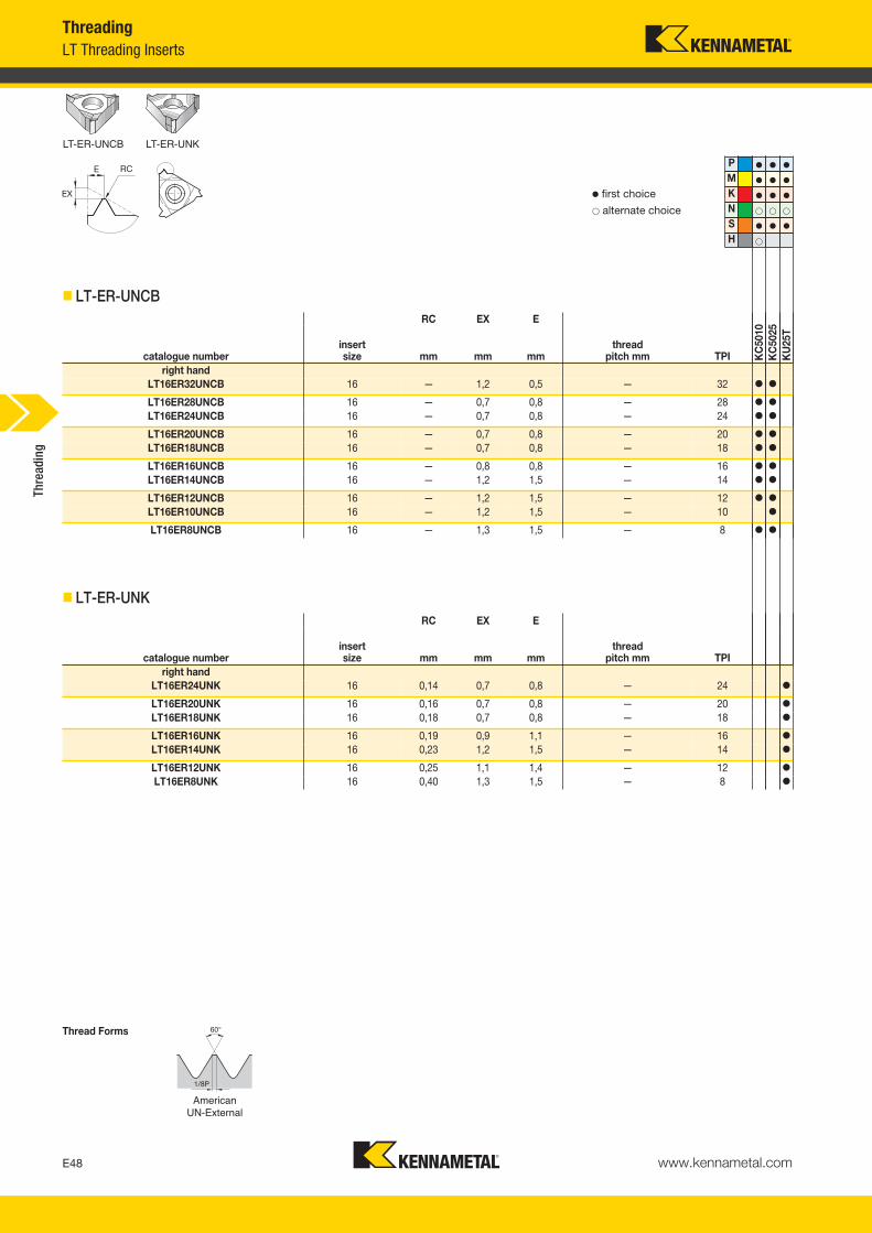
www.kennametal.comE48
American UN-External
� first choice� alternate choice
� LT-ER-UNCB
� LT-ER-UNK
Thread Forms
P � � �
M � � �
K � � �
N � � �
S � � �
H �
LT-ER-UNCB LT-ER-UNK
ThreadingLT Threading Inserts
RC EX E
catalogue numberinsertsize mm mm mm
thread pitch mm TPI K
C50
10K
C50
25K
U25
T
right handLT16ER32UNCB 16 — 1,2 0,5 — 32 � �
LT16ER28UNCB 16 — 0,7 0,8 — 28 � �
LT16ER24UNCB 16 — 0,7 0,8 — 24 � �
LT16ER20UNCB 16 — 0,7 0,8 — 20 � �
LT16ER18UNCB 16 — 0,7 0,8 — 18 � �
LT16ER16UNCB 16 — 0,8 0,8 — 16 � �
LT16ER14UNCB 16 — 1,2 1,5 — 14 � �
LT16ER12UNCB 16 — 1,2 1,5 — 12 � �
LT16ER10UNCB 16 — 1,2 1,5 — 10 �
LT16ER8UNCB 16 — 1,3 1,5 — 8 � �
RC EX E
catalogue numberinsertsize mm mm mm
thread pitch mm TPI
right handLT16ER24UNK 16 0,14 0,7 0,8 — 24 �
LT16ER20UNK 16 0,16 0,7 0,8 — 20 �
LT16ER18UNK 16 0,18 0,7 0,8 — 18 �
LT16ER16UNK 16 0,19 0,9 1,1 — 16 �
LT16ER14UNK 16 0,23 1,2 1,5 — 14 �
LT16ER12UNK 16 0,25 1,1 1,4 — 12 �
LT16ER8UNK 16 0,40 1,3 1,5 — 8 �
Thre
adin
g
KM_Master12_Turning_E048_E049_Metric.qxp:Layout 1 3/6/12 2:13 PM Page E48

www.kennametal.com E49
American UN-External
� first choice� alternate choice
� LT-ER/L-UN
Thread Forms
P � � �
M � � �
K � � �
N � � �
S � � �
H �
ThreadingLT Threading Inserts
LT-E-UN
RC EX E
catalogue numberinsertsize mm mm mm
thread pitch mm TPI K
C50
10K
C50
25K
U25
T
right handLT16ER48UN 16 — 0,6 0,6 — 48 �
LT16ER40UN 16 — 0,6 0,6 — 40 �
LT16ER36UN 16 — 0,6 0,6 — 36 �
LT16ER32UN 16 — 0,6 0,6 — 32 � �
LT16ER28UN 16 — 0,6 0,7 — 28 � �
LT16ER24UN 16 — 0,7 0,8 — 24 � �
LT16ER20UN 16 — 0,8 0,9 — 20 � �
LT16ER18UN 16 — 0,8 1,0 — 18 � �
LT16ER16UN 16 — 0,9 1,1 — 16 � �
LT16ER14UN 16 — 1,0 1,2 — 14 � �
LT16ER12UN 16 — 1,1 1,4 — 12 � �
LT16ER10UN 16 — 1,1 1,5 — 10 �
LT16ER8UN 16 — 1,2 1,6 — 8 �
left handLT16EL28UN 16 — 0,6 0,7 — 28 �
LT16EL24UN 16 — 0,7 0,8 — 24 �
LT16EL20UN 16 — 0,8 0,9 — 20 �
LT16EL18UN 16 — 0,8 1,0 — 18 �
LT16EL16UN 16 — 0,9 1,1 — 16 �
LT16EL14UN 16 — 1,0 1,2 — 14 �
LT16EL12UN 16 — 1,1 1,4 — 12 �
LT16EL11UN 16 — 1,1 1,4 — 11 �
LT16EL8UN 16 — 1,2 1,6 — 8 �
Thre
adin
g
KM_Master12_Turning_E048_E049_Metric.qxp:Layout 1 3/6/12 2:13 PM Page E49
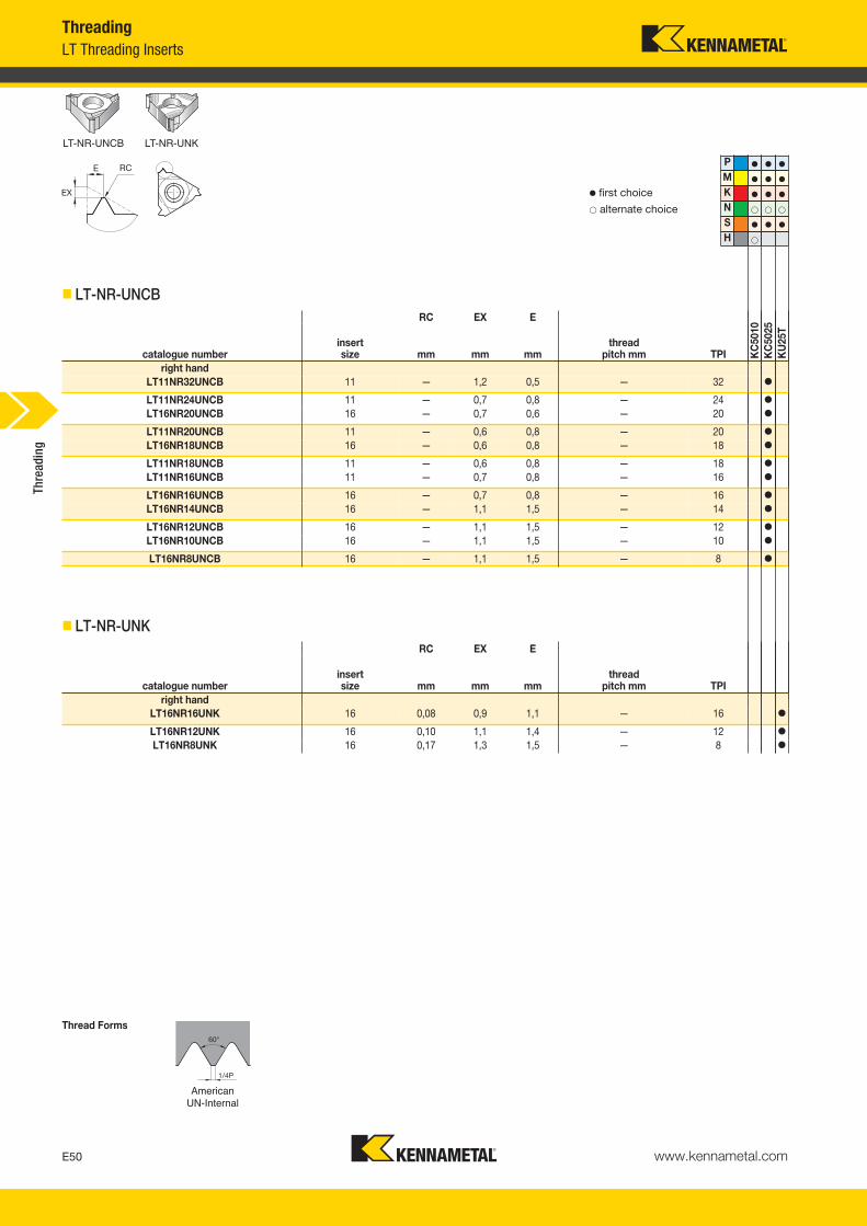
www.kennametal.comE50
American UN-Internal
� first choice� alternate choice
� LT-NR-UNCB
Thread Forms
� LT-NR-UNK
LT-NR-UNCB LT-NR-UNK
P � � �
M � � �
K � � �
N � � �
S � � �
H �
ThreadingLT Threading Inserts
RC EX E
catalogue numberinsertsize mm mm mm
thread pitch mm TPI K
C50
10K
C50
25K
U25
T
right handLT11NR32UNCB 11 — 1,2 0,5 — 32 �
LT11NR24UNCB 11 — 0,7 0,8 — 24 �
LT16NR20UNCB 16 — 0,7 0,6 — 20 �
LT11NR20UNCB 11 — 0,6 0,8 — 20 �
LT16NR18UNCB 16 — 0,6 0,8 — 18 �
LT11NR18UNCB 11 — 0,6 0,8 — 18 �
LT11NR16UNCB 11 — 0,7 0,8 — 16 �
LT16NR16UNCB 16 — 0,7 0,8 — 16 �
LT16NR14UNCB 16 — 1,1 1,5 — 14 �
LT16NR12UNCB 16 — 1,1 1,5 — 12 �
LT16NR10UNCB 16 — 1,1 1,5 — 10 �
LT16NR8UNCB 16 — 1,1 1,5 — 8 �
RC EX E
catalogue numberinsertsize mm mm mm
thread pitch mm TPI
right handLT16NR16UNK 16 0,08 0,9 1,1 — 16 �
LT16NR12UNK 16 0,10 1,1 1,4 — 12 �
LT16NR8UNK 16 0,17 1,3 1,5 — 8 �
Thre
adin
g
KM_Master12_Turning_E050_E051_Metric.qxp:Layout 1 3/6/12 2:13 PM Page E50
www.kennametal.com E51
American UN-Internal
� first choice� alternate choice
� LT-NR/L-UN
Thread Forms
P � � �
M � � �
K � � �
N � � �
S � � �
H �
ThreadingLT Threading Inserts
LT-NR/L-UN
RC EX E
catalogue numberinsertsize mm mm mm
thread pitch mm TPI K
C50
10K
C50
25K
U25
T
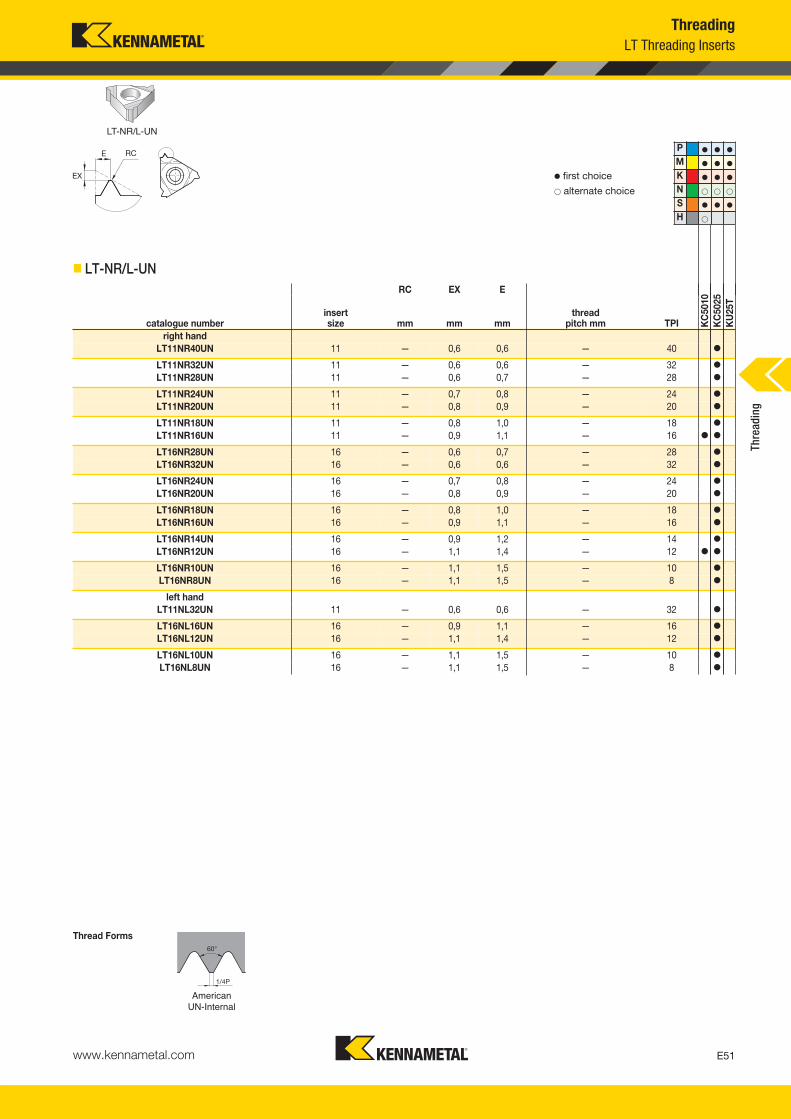
right handLT11NR40UN 11 — 0,6 0,6 — 40 �
LT11NR32UN 11 — 0,6 0,6 — 32 �
LT11NR28UN 11 — 0,6 0,7 — 28 �
LT11NR24UN 11 — 0,7 0,8 — 24 �
LT11NR20UN 11 — 0,8 0,9 — 20 �
LT11NR18UN 11 — 0,8 1,0 — 18 �
LT11NR16UN 11 — 0,9 1,1 — 16 � �
LT16NR28UN 16 — 0,6 0,7 — 28 �
LT16NR32UN 16 — 0,6 0,6 — 32 �
LT16NR24UN 16 — 0,7 0,8 — 24 �
LT16NR20UN 16 — 0,8 0,9 — 20 �
LT16NR18UN 16 — 0,8 1,0 — 18 �
LT16NR16UN 16 — 0,9 1,1 — 16 �
LT16NR14UN 16 — 0,9 1,2 — 14 �
LT16NR12UN 16 — 1,1 1,4 — 12 � �
LT16NR10UN 16 — 1,1 1,5 — 10 �
LT16NR8UN 16 — 1,1 1,5 — 8 �
left handLT11NL32UN 11 — 0,6 0,6 — 32 �
LT16NL16UN 16 — 0,9 1,1 — 16 �
LT16NL12UN 16 — 1,1 1,4 — 12 �
LT16NL10UN 16 — 1,1 1,5 — 10 �
LT16NL8UN 16 — 1,1 1,5 — 8 �
Thre
adin
g
KM_Master12_Turning_E050_E051_Metric.qxp:Layout 1 3/6/12 2:13 PM Page E51

www.kennametal.comE52
60°
1/8P
Rmax.1804PRmin .1501P
UNJ-External
� first choice� alternate choice
� LT-ER/L-UNJ
5/16P
UNJ-Internal
� LT-NR/L-UNJ
Thread Forms
LT-ER/L-UNJ LT-NR/L-UNJ
P � � �
M � � �
K � � �
N � � �
S � � �
H �
ThreadingLT Threading Inserts
RC EX E
catalogue numberinsertsize mm mm mm
thread pitch mm TPI K
C50
10K
C50
25K
U25
T
right handLT16ER32UNJ 16 — 0,6 0,7 — 32 �
LT16ER28UNJ 16 — 0,7 0,7 — 28 �
LT16ER24UNJ 16 — 0,7 0,8 — 24 �
LT16ER20UNJ 16 — 0,8 0,9 — 20 � �
LT16ER18UNJ 16 — 0,8 1,0 — 18 � �
LT16ER16UNJ 16 — 0,9 1,1 — 16 � �
LT16ER14UNJ 16 — 1,0 1,2 — 14 � �
LT16ER12UNJ 16 — 1,1 1,3 — 12 � �
left hand
LT16EL16UNJ 16 — 0,9 1,1 — 16 �
RC EX E
catalogue numberinsertsize mm mm mm
thread pitch mm TPI
right handLT11NR18UNJ 11 — 0,8 1,0 — 18 �
LT11NR16UNJ 11 — 0,9 1,1 — 16 �
LT16NR16UNJ 16 — 0,9 1,1 — 16 �
LT11NR14UNJ 11 — 1,0 1,2 — 14 �
LT16NR12UNJ 16 — 1,1 1,3 — 12 �
Thre
adin
g
KM_Master12_Turning_E052_E053_Metric.qxp:Layout 1 3/6/12 2:13 PM Page E52

www.kennametal.com E53
NPT-External
� first choice� alternate choice
� LT-ER-NPTCB
� LT-ER/L-NPT
NPT-Internal
� LT-NR-NPTCB
Thread Forms
LT-ER-NPTCB LT-ER/L-NPT LT-NR-NPTCB
P � � �
M � � �
K � � �
N � � �
S � � �
H �
ThreadingLT Threading Inserts
RC EX E
catalogue numberinsertsize mm mm mm
thread pitch mm TPI K
C50
10K
C50
25K
U25
T
right handLT16ER14NPTCB 16 — 1,1 1,5 — 14 � �
RC EX E
catalogue numberinsertsize mm mm mm
thread pitch mm TPI
right handLT16ER27NPT 16 — 0,7 0,8 — 27 �
LT16ER18NPT 16 — 0,8 1,0 — 18 � �
LT16ER14NPT 16 — 0,9 1,2 — 14 � �
LT16ER115NPT 16 — 1,1 1,5 — 11.5 � �
LT16ER8NPT 16 — 1,3 1,8 — 8 �
RC EX E
catalogue numberinsertsize mm mm mm
thread pitch mm TPI
right handLT16NR14NPTCB 16 — 1,35 1,20 — 14 �
LT16NR115NPTCB 16 — 1,10 1,50 — 11.5 �
Thre
adin
g
KM_Master12_Turning_E052_E053_Metric.qxp:Layout 1 3/6/12 2:13 PM Page E53

www.kennametal.comE54
NPT-Internal
� first choice� alternate choice
� LT-NR/L-NPT
NPTF-External
� LT-ER-NPTFCB
� LT-ER/L-NPTF
Thread Forms
LT-NR/L-NPT LT-ER-NPTFCB LT-ER/L-NPTF
P � � �
M � � �
K � � �
N � � �
S � � �
H �
ThreadingLT Threading Inserts
RC EX E
catalogue numberinsertsize mm mm mm
thread pitch mm TPI K
C50
10K
C50
25K
U25
T
right handLT11NR18NPT 11 — 0,8 1,0 — 18 �
LT11NR14NPT 11 — 0,8 1,0 — 14 � �
LT16NR14NPT 16 — 0,9 1,2 — 14 �
LT16NR115NPT 16 — 1,1 1,5 — 11.5 � �
LT16NR8NPT 16 — 1,3 1,8 — 8 �
RC EX E
catalogue numberinsertsize mm mm mm
thread pitch mm TPI
LT16ER115NPTFCB 16 — 1,1 1,5 — 11.5 �
RC EX E
catalogue numberinsertsize mm mm mm
thread pitch mm TPI
right handLT16ER14NPTF 16 — 0,9 1,2 — 14 �
LT16ER115NPTF 16 — 1,1 1,5 — 11.5 �
Thre
adin
g
KM_Master12_Turning_E054_E055_Metric.qxp:Layout 1 3/6/12 2:14 PM Page E54
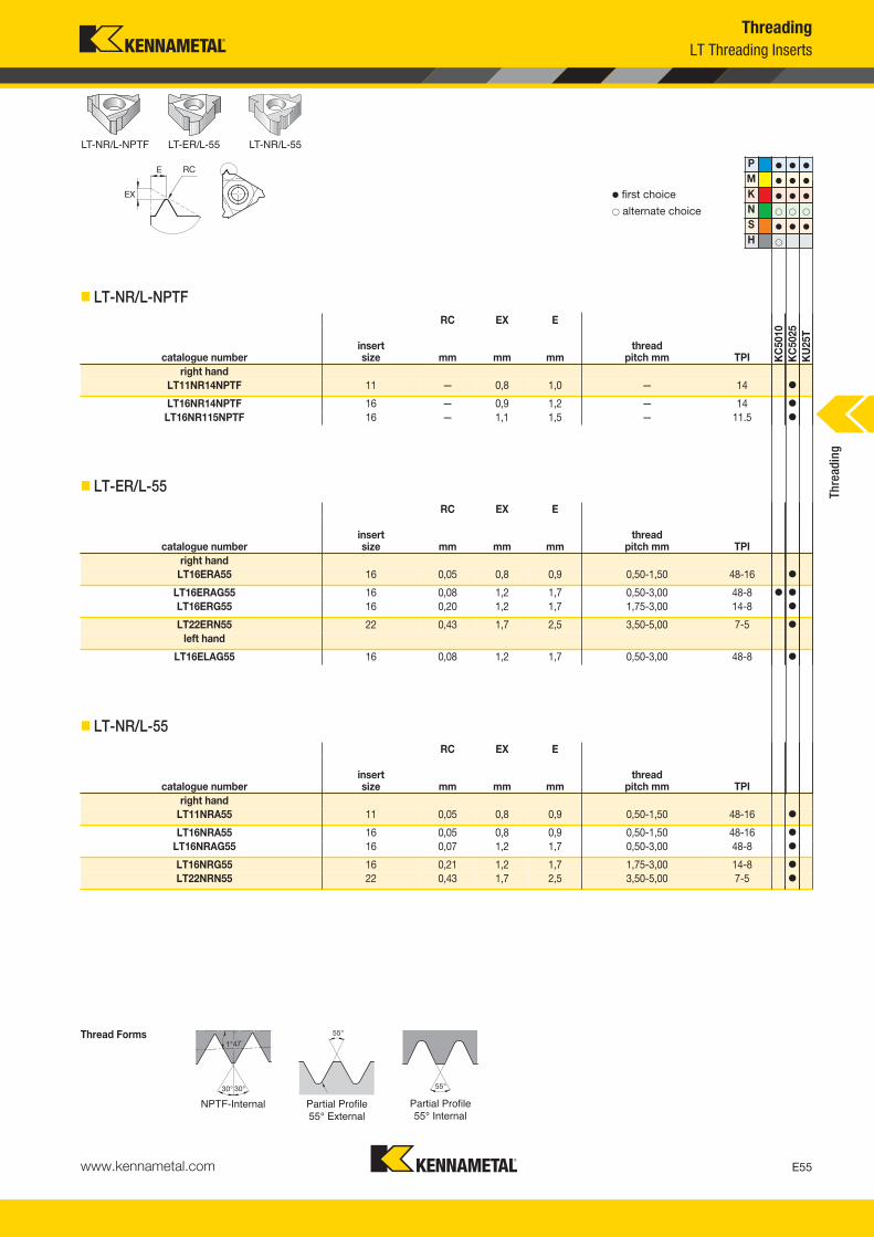
www.kennametal.com E55
NPTF-Internal
� first choice� alternate choice
� LT-NR/L-NPTF
Partial Profile 55° External
� LT-ER/L-55
Partial Profile 55° Internal
� LT-NR/L-55
Thread Forms
LT-NR/L-NPTF LT-ER/L-55 LT-NR/L-55
P � � �
M � � �
K � � �
N � � �
S � � �
H �
ThreadingLT Threading Inserts
RC EX E
catalogue numberinsertsize mm mm mm
thread pitch mm TPI K
C50
10K
C50
25K
U25
T
right handLT11NR14NPTF 11 — 0,8 1,0 — 14 �
LT16NR14NPTF 16 — 0,9 1,2 — 14 �
LT16NR115NPTF 16 — 1,1 1,5 — 11.5 �
RC EX E
catalogue numberinsertsize mm mm mm
thread pitch mm TPI
right handLT16ERA55 16 0,05 0,8 0,9 0,50-1,50 48-16 �
LT16ERAG55 16 0,08 1,2 1,7 0,50-3,00 48-8 � �
LT16ERG55 16 0,20 1,2 1,7 1,75-3,00 14-8 �
LT22ERN55 22 0,43 1,7 2,5 3,50-5,00 7-5 �
left hand
LT16ELAG55 16 0,08 1,2 1,7 0,50-3,00 48-8 �
RC EX E
catalogue numberinsertsize mm mm mm
thread pitch mm TPI
right handLT11NRA55 11 0,05 0,8 0,9 0,50-1,50 48-16 �
LT16NRA55 16 0,05 0,8 0,9 0,50-1,50 48-16 �
LT16NRAG55 16 0,07 1,2 1,7 0,50-3,00 48-8 �
LT16NRG55 16 0,21 1,2 1,7 1,75-3,00 14-8 �
LT22NRN55 22 0,43 1,7 2,5 3,50-5,00 7-5 �
Thre
adin
g
KM_Master12_Turning_E054_E055_Metric.qxp:Layout 1 3/6/12 2:14 PM Page E55
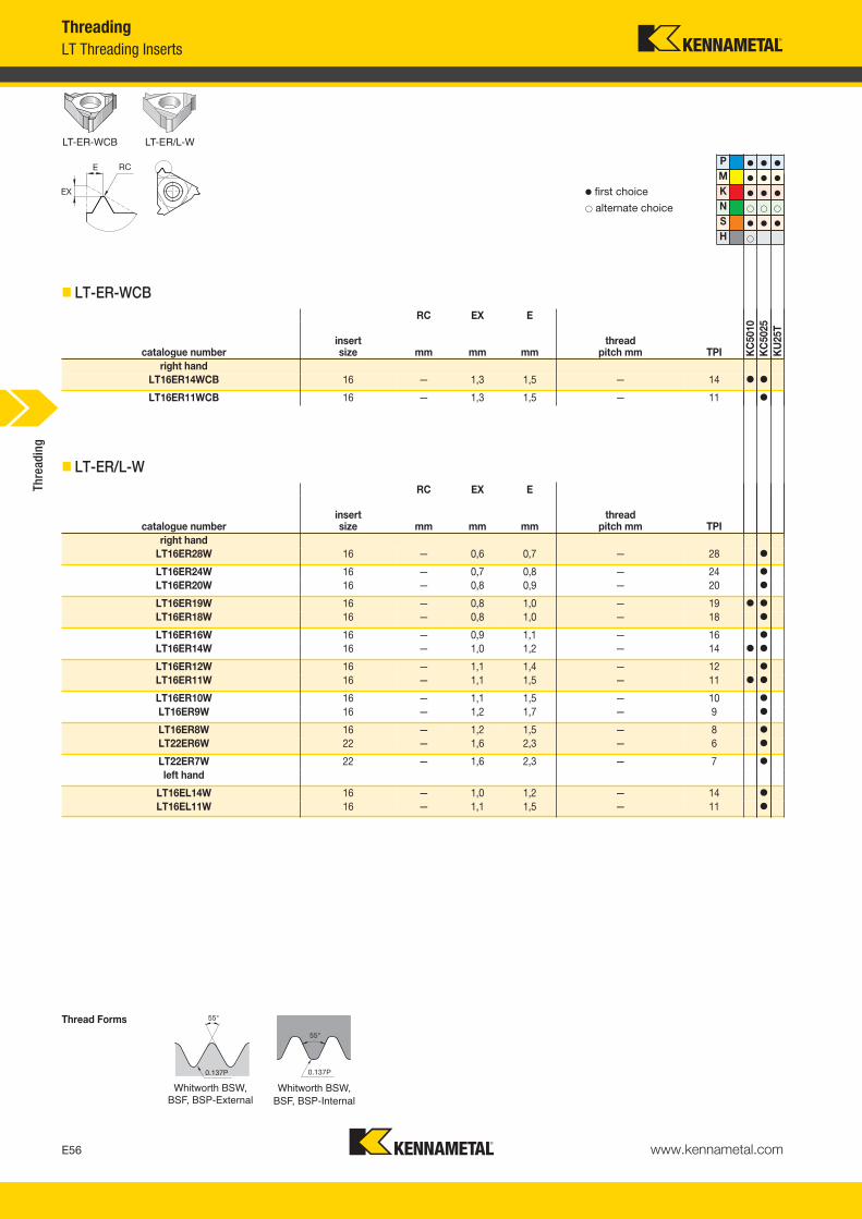
www.kennametal.comE56
0.137P
P � � �
M � � �
K � � �
N � � �
S � � �
H �
Whitworth BSW, BSF, BSP-External
� first choice� alternate choice
� LT-ER-WCB
0.137P
Whitworth BSW,BSF, BSP-Internal
� LT-ER/L-W
Thread Forms
LT-ER-WCB LT-ER/L-W
ThreadingLT Threading Inserts
RC EX E
catalogue numberinsertsize mm mm mm
thread pitch mm TPI K
C50
10K
C50
25K
U25
T
right handLT16ER14WCB 16 — 1,3 1,5 — 14 � �
LT16ER11WCB 16 — 1,3 1,5 — 11 �
RC EX E
catalogue numberinsertsize mm mm mm
thread pitch mm TPI
right handLT16ER28W 16 — 0,6 0,7 — 28 �
LT16ER24W 16 — 0,7 0,8 — 24 �
LT16ER20W 16 — 0,8 0,9 — 20 �
LT16ER19W 16 — 0,8 1,0 — 19 � �
LT16ER18W 16 — 0,8 1,0 — 18 �
LT16ER16W 16 — 0,9 1,1 — 16 �
LT16ER14W 16 — 1,0 1,2 — 14 � �
LT16ER12W 16 — 1,1 1,4 — 12 �
LT16ER11W 16 — 1,1 1,5 — 11 � �
LT16ER10W 16 — 1,1 1,5 — 10 �
LT16ER9W 16 — 1,2 1,7 — 9 �
LT16ER8W 16 — 1,2 1,5 — 8 �
LT22ER6W 22 — 1,6 2,3 — 6 �
LT22ER7W 22 — 1,6 2,3 — 7 �
left hand
LT16EL14W 16 — 1,0 1,2 — 14 �
LT16EL11W 16 — 1,1 1,5 — 11 �
Thre
adin
g
KM_Master12_Turning_E056_E057_Metric.qxp:Layout 1 3/6/12 2:14 PM Page E56
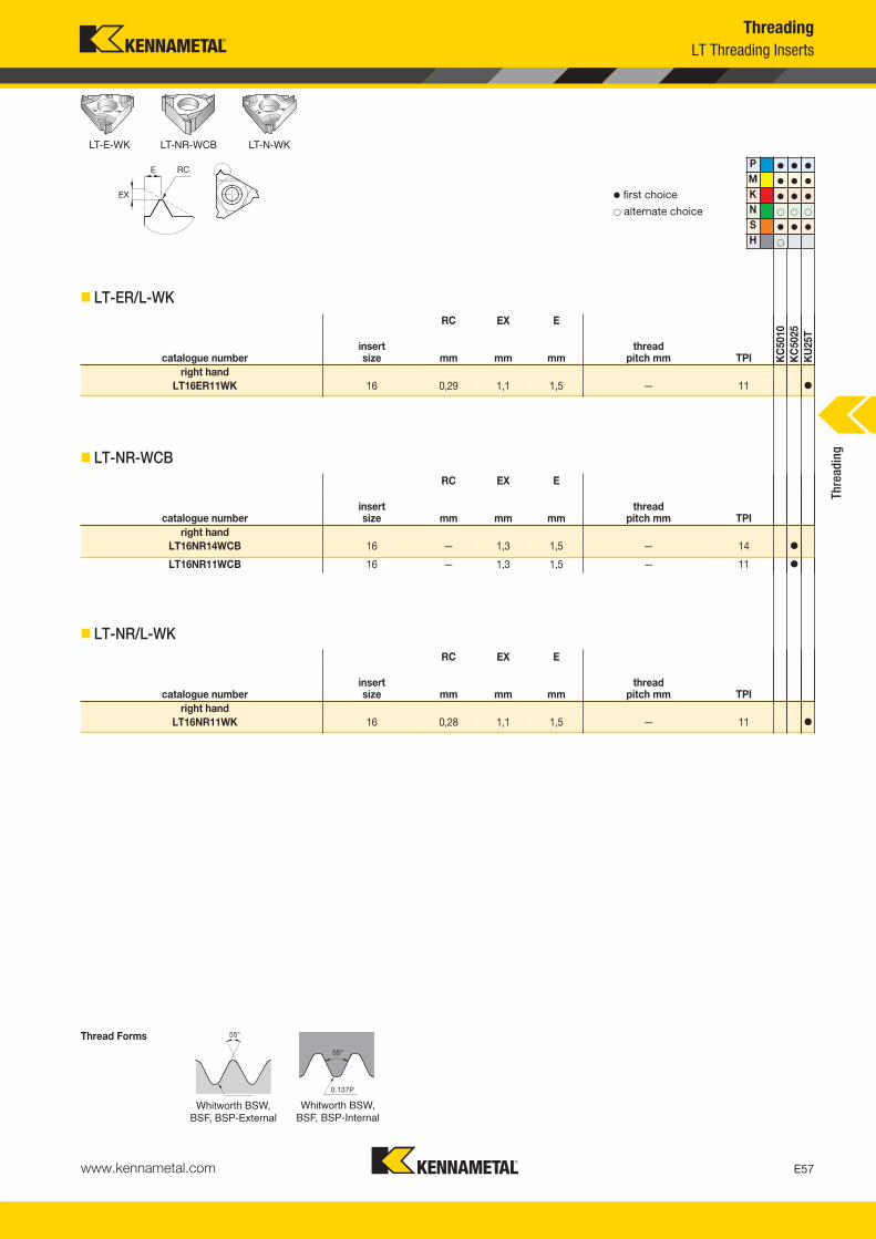
www.kennametal.com E57
Whitworth BSW,BSF, BSP-External
� first choice� alternate choice
� LT-ER/L-WK
0.137P
Whitworth BSW, BSF, BSP-Internal
� LT-NR-WCB
� LT-NR/L-WK
Thread Forms
LT-E-WK LT-NR-WCB LT-N-WK
P � � �
M � � �
K � � �
N � � �
S � � �
H �
ThreadingLT Threading Inserts
RC EX E
catalogue numberinsertsize mm mm mm
thread pitch mm TPI K
C50
10K
C50
25K
U25
T
right handLT16ER11WK 16 0,29 1,1 1,5 — 11 �
RC EX E
catalogue numberinsertsize mm mm mm
thread pitch mm TPI
right handLT16NR14WCB 16 — 1,3 1,5 — 14 �
LT16NR11WCB 16 — 1,3 1,5 — 11 �
RC EX E
catalogue numberinsertsize mm mm mm
thread pitch mm TPI
right handLT16NR11WK 16 0,28 1,1 1,5 — 11 �
Thre
adin
g
KM_Master12_Turning_E056_E057_Metric.qxp:Layout 1 3/6/12 2:14 PM Page E57

www.kennametal.comE58
Whitworth BSW,BSF, BSP-Internal
� first choice� alternate choice
� LT-NR/L-W
27.5° 27.5°
0.137P
BSPT-External
� LT-ER/L-BSPT
Thread Forms
P � � �
M � � �
K � � �
N � � �
S � � �
H �
LT-NR/L-W LT-ER/L-BSPT
ThreadingLT Threading Inserts
RC EX E
catalogue numberinsertsize mm mm mm
thread pitch mm TPI K
C50
10K
C50
25K
U25
T
right handLT16NR20W 16 — 0,8 0,9 — 20 �
LT11NR19W 11 — 0,8 1,0 — 19 �
LT16NR19W 16 — 0,8 1,0 — 19 �
LT16NR16W 16 — 0,9 1,1 — 16 �
LT11NR14W 11 — 0,9 1,1 — 14 �
LT16NR14W 16 — 1,0 1,2 — 14 �
LT16NR12W 16 — 1,1 1,4 — 12 �
LT16NR11W 16 — 1,1 1,5 — 11 � �
LT16NR10W 16 — 1,1 1,5 — 10 �
LT16NR8W 16 — 1,2 1,5 — 8 �
LT22NR6W 22 — 1,6 2,3 — 6 �
LT22NR7W 22 — 1,6 2,3 — 7 �
left hand
LT16NL11W 16 — 1,1 1,5 — 11 �
RC EX E
catalogue numberinsertsize mm mm mm
thread pitch mm TPI
right handLT16ER14BSPT 16 — 1,0 1,2 — 14 �
LT16ER11BSPT 16 — 1,1 1,5 — 11 �
Thre
adin
g
KM_Master12_Turning_E058_E059_Metric.qxp:Layout 1 3/6/12 2:14 PM Page E58

www.kennametal.com E59
BSPT-Internal
� first choice� alternate choice
� LT-NR/L-BSPT
API Rotary Shoulder Connections-External
α = 1/2 arctan (TPF/12)
� LT-ER/L-API
API Rotary Shoulder Connections-Internal
α = 1/2 arctan (TPF/12)
� LT-NR/L-API
Thread Forms
LT-NR/L-BSPT LT-ER/L-API LT-NR/L-API
P � � �
M � � �
K � � �
N � � �
S � � �
H �
ThreadingLT Threading Inserts
RC EX E
catalogue numberinsertsize mm mm mm
thread pitch mm TPI K
C50
10K
C50
25K
U25
T
right handLT11NR14BSPT 11 — 0,9 1,0 — 14 �
LT16NR14BSPT 16 — 1,0 1,2 — 14 �
LT16NR11BSPT 16 — 1,1 1,5 — 11 �
RC EX E
catalogue numberinsertsize mm mm mm
thread pitch mm TPI
right handLT27ER5API403 28 0,51 2,0 2,8 — 5 �
LT22ER5API403 22 — 1,8 2,6 — 5 �
LT27ER4API383 28 0,97 2,0 2,8 — 4 �
LT27ER4API382 28 0,97 2,0 2,8 — 4 �
LT22ER4API382 22 — 2,1 2,8 — 4 �
LT27ER4API503 28 0,64 2,0 2,8 — 4 �
LT27ER4API502 28 0,64 2,0 2,8 — 4 �
LT22ER4API503 22 — 2,0 2,9 — 4 �
LT22ER4API502 22 — 2,0 2,9 — 4 � �
RC EX E
catalogue numberinsertsize mm mm mm
thread pitch mm TPI
right handLT27NR5API403 28 0,52 2,0 2,8 — 5 �
LT27NR4API383 28 0,99 2,0 2,8 — 4 �
LT27NR4API382 28 0,99 2,0 2,8 — 4 �
LT22NR5API403 22 — 1,8 2,6 — 5 �
LT22NR4API382 22 — 2,1 2,8 — 4 �
LT27NR4API503 28 0,65 2,0 2,8 — 4 �
LT27NR4API502 28 0,65 2,0 3,8 — 4 �
LT22NR4API502 22 — 2,1 3,1 — 4 �
Thre
adin
g
KM_Master12_Turning_E058_E059_Metric.qxp:Layout 1 3/6/12 2:14 PM Page E59
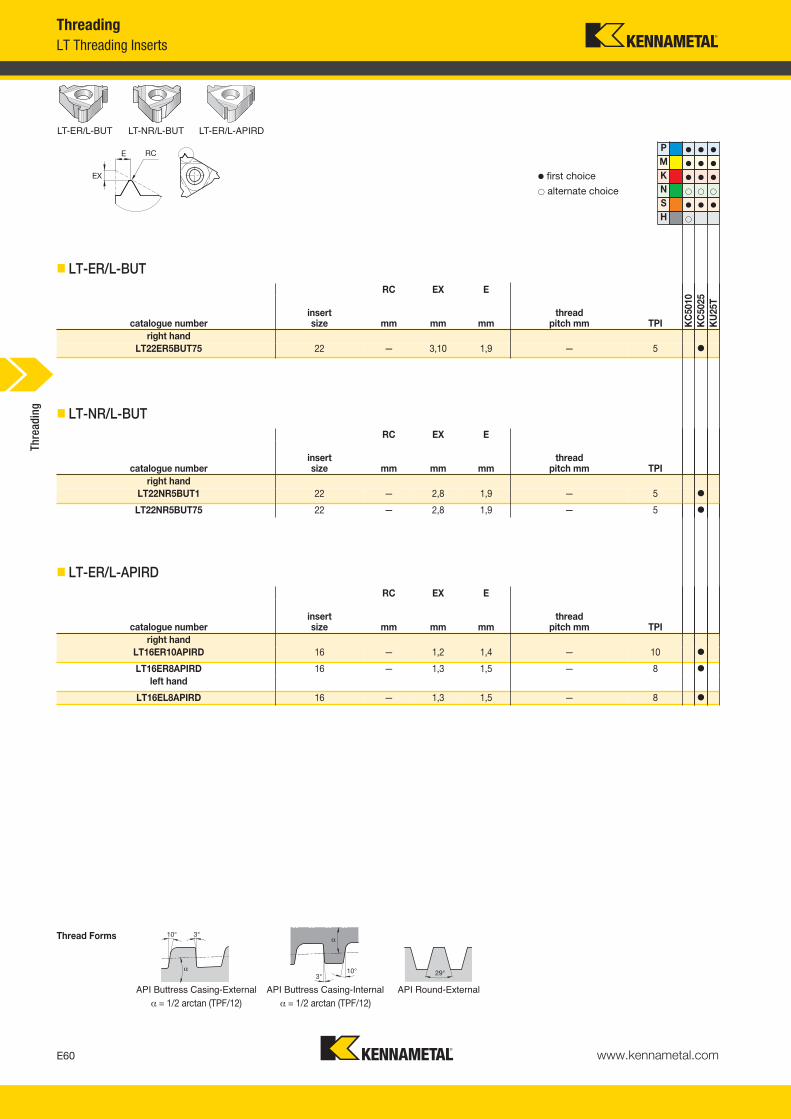
www.kennametal.comE60
API Buttress Casing-External
α = 1/2 arctan (TPF/12)
� first choice� alternate choice
� LT-ER/L-BUT
API Buttress Casing-Internal
α = 1/2 arctan (TPF/12)
� LT-NR/L-BUT
API Round-External
� LT-ER/L-APIRD
Thread Forms
LT-ER/L-BUT LT-NR/L-BUT LT-ER/L-APIRD
P � � �
M � � �
K � � �
N � � �
S � � �
H �
ThreadingLT Threading Inserts
RC EX E
catalogue numberinsertsize mm mm mm
thread pitch mm TPI K
C50
10K
C50
25K
U25
T
right handLT22ER5BUT75 22 — 3,10 1,9 — 5 �
RC EX E
catalogue numberinsertsize mm mm mm
thread pitch mm TPI
right handLT22NR5BUT1 22 — 2,8 1,9 — 5 �
LT22NR5BUT75 22 — 2,8 1,9 — 5 �
RC EX E
catalogue numberinsertsize mm mm mm
thread pitch mm TPI
right handLT16ER10APIRD 16 — 1,2 1,4 — 10 �
LT16ER8APIRD 16 — 1,3 1,5 — 8 �
left hand
LT16EL8APIRD 16 — 1,3 1,5 — 8 �
Thre
adin
g
KM_Master12_Turning_E060_E061_Metric.qxp:Layout 1 3/6/12 2:14 PM Page E60
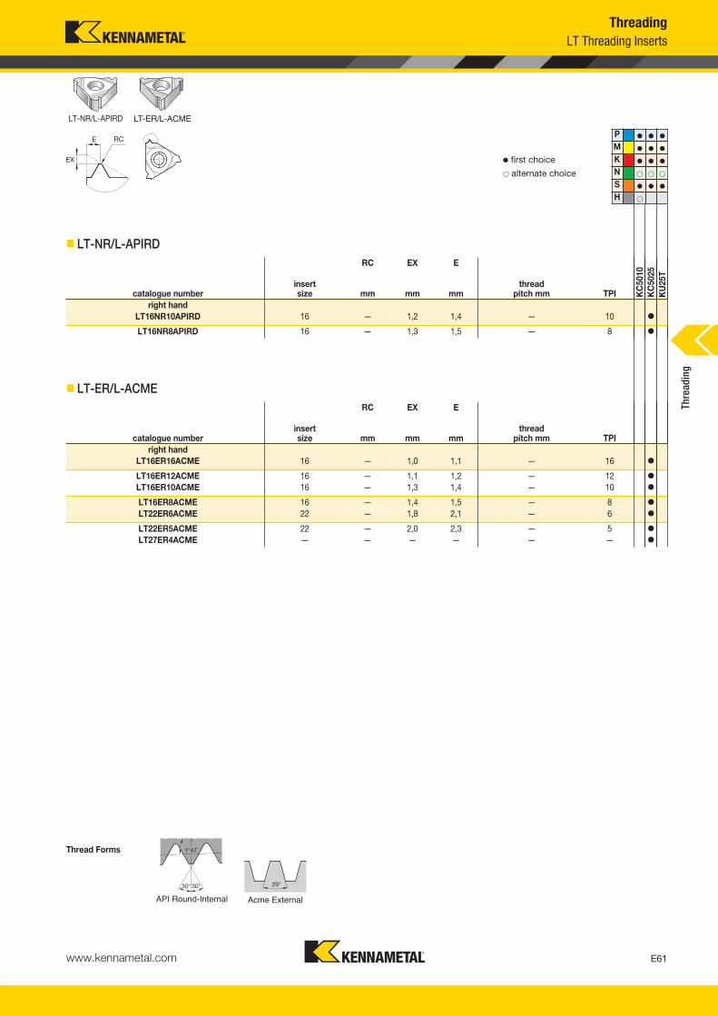
www.kennametal.com E61
API Round-Internal
� first choice� alternate choice
� LT-NR/L-APIRD
Acme External
� LT-ER/L-ACME
Thread Forms
LT-NR/L-APIRD LT-ER/L-ACME
P � � �
M � � �
K � � �
N � � �
S � � �
H �
ThreadingLT Threading Inserts
RC EX E
catalogue numberinsertsize mm mm mm
thread pitch mm TPI K
C50
10K
C50
25K
U25
T
right handLT16NR10APIRD 16 — 1,2 1,4 — 10 �
LT16NR8APIRD 16 — 1,3 1,5 — 8 �
RC EX E
catalogue numberinsertsize mm mm mm
thread pitch mm TPI
right handLT16ER16ACME 16 — 1,0 1,1 — 16 �
LT16ER12ACME 16 — 1,1 1,2 — 12 �
LT16ER10ACME 16 — 1,3 1,4 — 10 �
LT16ER8ACME 16 — 1,4 1,5 — 8 �
LT22ER6ACME 22 — 1,8 2,1 — 6 �
LT22ER5ACME 22 — 2,0 2,3 — 5 �
LT27ER4ACME — — — — — — �
Thre
adin
g
KM_Master12_Turning_E060_E061_Metric.qxp:Layout 1 3/6/12 2:14 PM Page E61
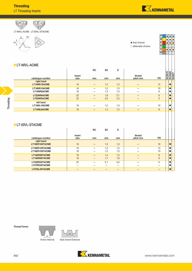
www.kennametal.comE62
Acme Internal
� first choice� alternate choice
� LT-NR/L-ACME
Stub Acme-External
� LT-ER/L-STACME
Thread Forms
P � � �
M � � �
K � � �
N � � �
S � � �
H �
LT-NR/L-ACME LT-ER/L-STACME
ThreadingLT Threading Inserts
RC EX E
catalogue numberinsertsize mm mm mm
thread pitch mm TPI K
C50
10K
C50
25K
U25
T
right handLT16NR12ACME 16 — 1,2 1,3 — 12 �
LT16NR10ACME 16 — 1,2 1,3 — 10 �
LT16NR8ACME 16 — 1,4 1,5 — 8 �
LT22NR6ACME 22 — 1,8 2,1 — 6 �
LT22NR5ACME 22 — 2,0 2,3 — 5 �
left handLT16NL10ACME 16 — 1,2 1,3 — 10 �
LT16NL8ACME 16 — 1,4 1,5 — 8 �
RC EX E
catalogue numberinsertsize mm mm mm
thread pitch mm TPI
right handLT16ER16STACME 16 — 1,0 1,0 — 16 �
LT16ER12STACME 16 — 1,2 1,2 — 12 �
LT16ER10STACME 16 — 1,2 1,3 — 10 �
LT16ER8STACME 16 — 1,4 1,5 — 8 �
LT16ER6STACME 16 — 1,7 1,8 — 6 �
LT22ER5STACME 22 — 2,1 2,3 — 5 �
LT27ER4STACME — — — — — — �
LT27EL4STACME — — — — — — �
Thre
adin
g
KM_Master12_Turning_E062_E063_Metric.qxp:Layout 1 3/6/12 2:14 PM Page E62

www.kennametal.com E63
Stub Acme-Internal
� first choice� alternate choice
� LT-NR/L-STACME
Trapez-External
� LT-ER/L-TR
Trapez-Internal
� LT-NR/L-TR
Thread Forms
LT-NR/L-STACME LT-ER/L-TR LT-NR/L-TR
P � � �
M � � �
K � � �
N � � �
S � � �
H �
ThreadingLT Threading Inserts
RC EX E
catalogue numberinsertsize mm mm mm
thread pitch mm TPI K
C50
10K
C50
25K
U25
T
right handLT16NR16STACME 16 — 1,0 1,0 — 16 �
LT16NR14STACME 16 — 1,1 1,1 — 14 �
LT16NR12STACME 16 — 1,1 1,2 — 12 �
LT16NR10STACME 16 — 1,2 1,3 — 10 �
LT16NR8STACME 16 — 1,4 1,5 — 8 �
LT16NR6STACME 16 — 1,7 1,8 — 6 �
LT22NR6STACME 22 — 1,8 1,8 — 6 �
LT27NL4STACME — — — — — — �
LT27NR4STACME — — — — — — �
RC EX E
catalogue numberinsertsize mm mm mm
thread pitch mm TPI
right handLT16ER2TR 16 — 1,1 1,3 2,0 — �
LT16ER3TR 16 — 1,3 1,5 3,0 — �
LT22ER4TR 22 — 1,7 1,9 4,0 — �
LT22ER5TR 22 — 2,1 2,5 5,0 — �
RC EX E
catalogue numberinsertsize mm mm mm
thread pitch mm TPI
right handLT16NR2TR 16 — 1,1 1,3 2,0 — �
LT16NR3TR 16 — 1,3 1,5 3,0 — �
LT22NR4TR 22 — 1,7 1,9 4,0 — �
LT22NR5TR 22 — 2,1 2,5 5,0 — �
Thre
adin
g
KM_Master12_Turning_E062_E063_Metric.qxp:Layout 1 3/6/12 2:14 PM Page E63
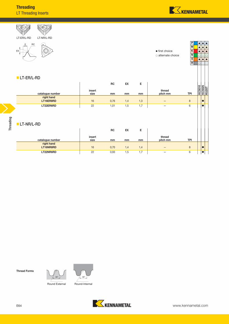
www.kennametal.comE64
Round External
� first choice� alternate choice
� LT-ER/L-RD
Round-Internal
� LT-NR/L-RD
Thread Forms
LT-ER/L-RD LT-NR/L-RD
P � � �
M � � �
K � � �
N � � �
S � � �
H �
ThreadingLT Threading Inserts
RC EX E
catalogue numberinsertsize mm mm mm
thread pitch mm TPI K
C50
10K
C50
25K
U25
T
right handLT16ER8RD 16 0,76 1,4 1,3 — 8 �
LT22ER6RD 22 1,01 1,5 1,7 — 6 �
RC EX E
catalogue numberinsertsize mm mm mm
thread pitch mm TPI
right handLT16NR8RD 16 0,70 1,4 1,4 — 8 �
LT22NR6RD 22 0,93 1,5 1,7 — 6 �
Thre
adin
g
KM_Master12_Turning_E064_E065_Metric.qxp:Layout 1 3/6/12 2:15 PM Page E64

Turning
Check the Kennametal website!
Visit http://www.kennametal.com/turning/ to browse our electronic catalogue any time you’re looking for Kennametal’s best tooling solutions. It’s fast, free, and always available. The online e-catalogue is updated weekly with products and solutions for milling, turning, holemaking, and tooling systems applications.
E65
KM_Master12_Turning_E064_E065_Metric.qxp:Layout 1 3/6/12 2:15 PM Page E65

www.kennametal.comE66
NOTE: For shims and shim kits, see pages E101–E103.
� LT Threading Shim Catalogue Numbering System
How Do Catalogue Numbers Work?Each character in our catalogue number signifies a specific trait of thatproduct. Use the following key columns and corresponding imagesto easily identify which attributes apply.
ASToolStyle
SInsert Holding
Method
LInsert Style
LSASR1212N16
RHand
of Tool
YSM
NOTE: Toolholders with primary shank sizes larger than 1/2" or 12mm are supplied with clamp and insert screw. Secure the insert with either the clamp or insert screw. Do not use both.
LT Threading Catalogue Numbering SystemThreading
S = Insert screw or clamp only
AS = Straight shank
S = Offset shank
L = Laydown triangle
L = Left hand
E 3 2PShim Shim for LT
Standard InsertsInsert
ThreadingInsert Size
Shim Angle
E = ExternalI = Internal
2P = 2º positive1P = 1º positive__ = 0º neutral1N = 1º negative2N = 2º negative3N = 3º negative
D value in 1/8"
R = Right hand
AS
S
L
R
Thre
adin
g
KM_Master12_Turning_E066_E067_Metric.qxp:Layout 1 3/6/12 2:15 PM Page E66

www.kennametal.com E67
16Insert Size
1212NShankSize
Drop Head
LSASR1212N16
Qualified Surfaceand Length
ThreadingLT Threading Catalogue Numbering System
metric:Shank height and width in mm and holder length according to ISO standard.
C = Qualified back andend, 5" long
D = Qualified back andend, 6" long
E = Qualified back andend, 7" long
T = Qualified back andend, 3.250" long
Q = Qualified metricholder
Size equals number of 1/8" increments of IC.
DH
insertsize
(inch)
insert size
(mm)D
(inch)L1
(mm)2 11 1/4 11,03 16 3/8 16,54 22 1/2 22,0
Thre
adin
g
By referencing this easy-to-use guide, you canidentify the correct product to meet your needs.
D
L1
KM_Master12_Turning_E066_E067_Metric.qxp:Layout 1 3/6/12 2:15 PM Page E67

www.kennametal.comE68
See page E41 for inserts.
� LSA
ThreadingLT Threading Toolholders
Thre
adin
g
catalogue number H B F L1 L2gageinsert shim
shim screw Torx
clamp assembly Torx
insert screw Torx
right handLSASR1212N16 12 12 16 85 22 LT16ER — — — — — SSA3T T10
LSASR1616H16 16 16 16 100 25 LT16ER SMYE3 SSY3T T10 CKC3 T15 SSA3T T10LSASR2020K16 20 20 20 125 30 LT16ER SMYE3 SSY3T T10 CKC3 T15 SSA3T T10
LSASR2525M16 25 25 25 150 30 LT16ER SMYE3 SSY3T T10 CKC3 T15 SSA3T T10LSASR3232P16 32 32 32 170 30 LT16ER SMYE3 SSY3T T10 CKC3 T15 SSA3T T10
LSASR2525M22 25 25 25 150 36 LT22ER SMYE4 SSY4T T20 CKC4 T20 SSA4T T20LSASR3232P22 32 32 32 170 36 LT22ER SMYE4 SSY4T T20 CKC4 T20 SSA4T T20
left handLSASL1212N16 12 12 16 85 22 LT16EL — — — — — SSA3T T10
LSASL1616H16 16 16 16 100 25 LT16EL SMYI3 SSY3T T10 CKC3 T15 SSA3T T10LSASL2020K16 20 20 20 125 30 LT16EL SMYI3 SSY3T T10 CKC3 T15 SSA3T T10
LSASL2525M16 25 25 25 150 30 LT16EL SMYI3 SSY3T T10 CKC3 T15 SSA3T T10LSASL2525M22 25 25 25 150 36 LT22EL SMYI4 SSY4T T20 CKC4 T20 SSA4T T20
KM_Master12_Turning_E068_E069_Metric.qxp:Layout 1 3/6/12 2:15 PM Page E68
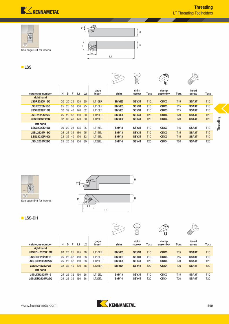
www.kennametal.com E69
F
2°H
B
L1L2
See page E41 for inserts.
� LSS
F
2°H
B
L1
L2
See page E41 for inserts.
� LSS-DHTh
read
ing
ThreadingLT Threading Toolholders
catalogue number H B F L1 L2gageinsert shim
shim screw Torx
clamp assembly Torx
insert screw Torx
right handLSSR2020K16Q 20 20 25 125 25 LT16ER SMYE3 SSY3T T10 CKC3 T15 SSA3T T10
LSSR2525M16Q 25 25 32 150 25 LT16ER SMYE3 SSY3T T10 CKC3 T15 SSA3T T10LSSR3232P16Q 32 32 40 170 32 LT16ER SMYE3 SSY3T T10 CKC3 T15 SSA3T T10
LSSR2525M22Q 25 25 32 150 30 LT22ER SMYE4 SSY4T T20 CKC4 T20 SSA4T T20LSSR3232P22Q 32 32 40 170 30 LT22ER SMYE4 SSY4T T20 CKC4 T20 SSA4T T20
left handLSSL2020K16Q 20 20 25 125 25 LT16EL SMYI3 SSY3T T10 CKC3 T15 SSA3T T10
LSSL2525M16Q 25 25 32 150 25 LT16EL SMYI3 SSY3T T10 CKC3 T15 SSA3T T10LSSL3232P16Q 32 32 40 170 32 LT16EL SMYI3 SSY3T T10 CKC3 T15 SSA3T T10
LSSL2525M22Q 25 25 32 150 30 LT22EL SMYI4 SSY4T T20 CKC4 T20 SSA4T T20
catalogue number H B F L1 L2gageinsert shim
shim screw Torx
clamp assembly Torx
insert screw Torx
right handLSSRDH2020K16Q 20 20 25 125 38 LT16ER SMYE3 SSY3T T10 CKC3 T15 SSA3T T10
LSSRDH2525M16 25 25 32 150 38 LT16ER SMYE3 SSY3T T10 CKC3 T15 SSA3T T10LSSRDH2525M22Q 25 25 32 150 38 LT22ER SMYE4 SSY4T T20 CKC4 T20 SSA4T T20
LSSRDH3232P22 32 32 40 170 38 LT22ER SMYE4 SSY4T T20 CKC4 T20 SSA4T T20left hand
LSSLDH2525M16 25 25 32 150 38 LT16EL SMYI3 SSY3T T10 CKC3 T15 SSA3T T10LSSLDH2525M22Q 25 25 32 150 38 LT22EL SMYI4 SSY4T T20 CKC4 T20 SSA4T T20
KM_Master12_Turning_E068_E069_Metric.qxp:Layout 1 3/6/12 2:15 PM Page E69

www.kennametal.comE70
A
A1010LSER11
10 10 LBar
TypePrimary Necked
Shank Bar DiameterSecondary (Mounting)
Bar DiameterInsertStyle
How Do Catalogue Numbers Work?Each character in our catalogue number signifies a specific trait of thatproduct. Use the following key columns and corresponding imagesto easily identify which attributes apply.
LT Threading Boring Bar Catalogue Numbering SystemThreading
NOTE: Boring bars with primary bar diameters larger than 5/8" or 16mm are supplied with clamp and insert screw. Secure the insert with either the clamp or insert screw. Do not use both.
A = Steel with coolant S = Steel without coolant E = Carbide with coolant H = Interchangeable headwith coolant
A two-digit number that indicates the secondary bar diameter in 1/16"increments. Metric diameter in mm.
L = Laydown triangle
A two-digit number that indicates the primary bar diameter in 1/16"increments. Metric diameter in mm.
NOTE: For shims and shim kits, see pages E101–E103.
� LT Threading Shim Catalogue Numbering System
YSM E 3 2PShim Shim for LT
Standard InsertsInsert
ThreadingInsert Size
Shim Angle
E = ExternalI = Internal
2P = 2º positive1P = 1º positive__ = 0º neutral1N = 1º negative2N = 2º negative3N = 3º negative
D value in 1/8"
Thre
adin
g
KM_Master12_Turning_E070_E071_Metric.qxp:Layout 1 3/27/12 10:47 AM Page E70
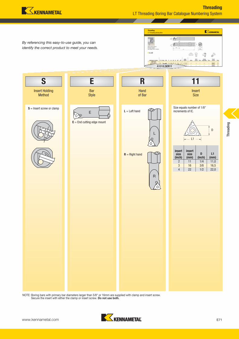
www.kennametal.com E71
S E R 11Insert Holding
MethodBar
StyleHandof Bar
InsertSize
S = Insert screw or clamp
A1010LSER11
ThreadingLT Threading Boring Bar Catalogue Numbering System
NOTE: Boring bars with primary bar diameters larger than 5/8" or 16mm are supplied with clamp and insert screw. Secure the insert with either the clamp or insert screw. Do not use both.
L = Left hand
R = Right hand
E = End cutting edge mount
Size equals number of 1/8"increments of IC.E
L
R
D
L1
insertsize
(inch)
insert size
(mm)D
(inch)L1
(mm)2 11 1/4 11,03 16 3/8 16,54 22 1/2 22,0
Thre
adin
g
By referencing this easy-to-use guide, you canidentify the correct product to meet your needs.
KM_Master12_Turning_E070_E071_Metric.qxp:Layout 1 3/27/12 10:47 AM Page E71
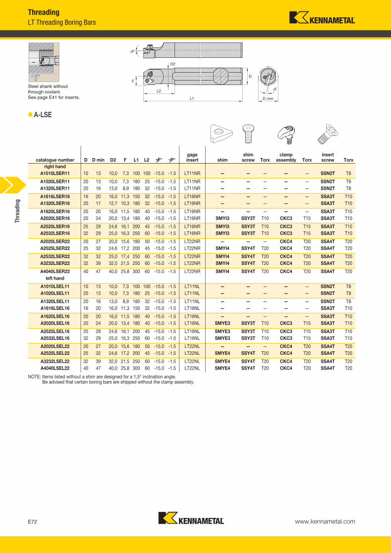
www.kennametal.comE72
Steel shank without through coolant.See page E41 for inserts.
� A-LSE
NOTE: Items listed without a shim are designed for a 1,5° inclination angle.Be advised that certain boring bars are shipped without the clamp assembly.
ThreadingLT Threading Boring Bars
Thre
adin
g
catalogue number D D min D2 F L1 L2 γγF° γP°gageinsert shim
shim screw Torx
clamp assembly Torx
insert screw Torx
right handA1010LSER11 10 13 10,0 7,3 100 100 -15.0 -1.5 LT11NR — — — — — SSN2T T8
A1020LSER11 20 13 10,0 7,3 180 25 -15.0 -1.5 LT11NR — — — — — SSN2T T8A1320LSER11 20 16 13,0 8,9 180 32 -15.0 -1.5 LT11NR — — — — — SSN2T T8
A1616LSER16 16 20 16,0 11,3 150 32 -15.0 -1.5 LT16NR — — — — — SSA3T T10A1320LSER16 20 17 12,7 10,3 180 32 -15.0 -1.5 LT16NR — — — — — SSA3T T10
A1620LSER16 20 20 16,0 11,5 180 40 -15.0 -1.5 LT16NR — — — — — SSA3T T10A2020LSER16 20 24 20,0 13,4 180 40 -15.0 -1.5 LT16NR SMYI3 SSY3T T10 CKC3 T15 SSA3T T10
A2525LSER16 25 29 24,6 16,1 200 45 -15.0 -1.5 LT16NR SMYI3 SSY3T T10 CKC3 T15 SSA3T T10A2532LSER16 32 29 25,0 16,3 250 60 -15.0 -1.5 LT16NR SMYI3 SSY3T T10 CKC3 T15 SSA3T T10
A2020LSER22 20 27 20,0 15,6 180 50 -15.0 -1.5 LT22NR — — — CKC4 T20 SSA4T T20A2525LSER22 25 32 24,6 17,2 200 45 -15.0 -1.5 LT22NR SMYI4 SSY4T T20 CKC4 T20 SSA4T T20
A2532LSER22 32 32 25,0 17,4 250 60 -15.0 -1.5 LT22NR SMYI4 SSY4T T20 CKC4 T20 SSA4T T20A3232LSER22 32 39 32,0 21,5 250 60 -15.0 -1.5 LT22NR SMYI4 SSY4T T20 CKC4 T20 SSA4T T20
A4040LSER22 40 47 40,0 25,8 300 60 -15.0 -1.5 LT22NR SMYI4 SSY4T T20 CKC4 T20 SSA4T T20left hand
A1010LSEL11 10 13 10,0 7,3 100 100 -15.0 -1.5 LT11NL — — — — — SSN2T T8A1020LSEL11 20 13 10,0 7,3 180 25 -15.0 -1.5 LT11NL — — — — — SSN2T T8
A1320LSEL11 20 16 13,0 8,9 180 32 -15.0 -1.5 LT11NL — — — — — SSN2T T8A1616LSEL16 16 20 16,0 11,3 150 32 -15.0 -1.5 LT16NL — — — — — SSA3T T10
A1620LSEL16 20 20 16,0 11,5 180 40 -15.0 -1.5 LT16NL — — — — — SSA3T T10A2020LSEL16 20 24 20,0 13,4 180 40 -15.0 -1.5 LT16NL SMYE3 SSY3T T10 CKC3 T15 SSA3T T10
A2525LSEL16 25 29 24,6 16,1 200 45 -15.0 -1.5 LT16NL SMYE3 SSY3T T10 CKC3 T15 SSA3T T10A2532LSEL16 32 29 25,0 16,3 250 60 -15.0 -1.5 LT16NL SMYE3 SSY3T T10 CKC3 T15 SSA3T T10
A2020LSEL22 20 27 20,0 15,6 180 50 -15.0 -1.5 LT22NL — — — CKC4 T20 SSA4T T20A2525LSEL22 25 32 24,6 17,2 200 45 -15.0 -1.5 LT22NL SMYE4 SSY4T T20 CKC4 T20 SSA4T T20
A3232LSEL22 32 39 32,0 21,5 250 60 -15.0 -1.5 LT22NL SMYE4 SSY4T T20 CKC4 T20 SSA4T T20A4040LSEL22 40 47 40,0 25,8 300 60 -15.0 -1.5 LT22NL SMYE4 SSY4T T20 CKC4 T20 SSA4T T20
KM_Master12_Turning_E072_E073_Metric.qxp:Layout 1 3/27/12 10:50 AM Page E72

www.kennametal.com E73
A
Carbide shank with through coolant.See page E41 for inserts.
� E-LSE
NOTE: All carbide bars need a KWH grade designation.
With through coolant.See page E41 for inserts.
NOTE: For boring adaptors, see pages C108–C109.
ThreadingLT Threading Boring Bars • Boring Heads
� H-LSE
Thre
adin
g
catalogue number D D min F L1 A γγF° γP°gageinsert shim
shim screw Torx
clamp assembly Torx
insert screw Torx
right handE16RLSER16 16 20 11,5 200 5,5 -15.0 -1.5 LT16NR — — — — — SN3TPKG T10
E20SLSER16 20 24 13,4 250 7,1 -15.0 -1.5 LT16NR SMYI3 SSY3T T10 CKC3 T15 SSA3T T10E25TLSER16 25 29 15,8 300 7,9 -15.0 -1.5 LT16NR SMYI3 SSY3T T10 CKC3 T15 SSA3T T10
catalogue number D D min L1 F γγF° γP°gageinsert shim
shim screw Torx
clamp assembly Torx
insert screw Torx
right handH16LSER3 25 30,5 41,3 16,4 -15.0 -1.5 LT16NR SMYI3 SSY3T T10 CKC3 T15 SSA3T T10
H20LSER3 32 36,8 41,3 19,3 -15.0 -1.5 LT16NR SMYI3 SSY3T T10 CKC3 T15 SSA3T T10H24LSER3 38 44,7 41,3 22,5 -15.0 -1.5 LT16NR SMYI3 SSY3T T10 CKC3 T15 SSA3T T10
H32LSER3 51 61,0 41,3 32,4 -15.0 -1.5 LT16NR SMYI3 SSY3T T10 CKC3 T15 SSA3T T10H50LSER16 50 54,0 41,3 27,2 -15.0 -1.5 LT16NR SMYI3 SSY3T T10 CKC3 T15 SSA3T T10
H24LSER4 38 45,3 41,3 24,7 -15.0 -1.5 LT22NR SMYI4 SSY4T T20 CKC4 T20 SSA4T T20H32LSER4 51 61,0 41,3 32,4 -15.0 -1.5 LT22NR SMYI4 SSY4T T20 CKC4 T20 SSA4T T20
H40LSER22 40 47,0 41,3 24,1 -15.0 -1.5 LT22NR SMYI4 SSY4T T20 CKC4 T20 SSA4T T20H50LSER22 50 56,0 41,3 28,7 -15.0 -1.5 LT22NR SMYI4 SSY4T T20 CKC4 T20 SSA4T T20
H32LSER5 51 61,0 41,3 32,5 -15.0 -1.5 LT27NR SMYI5 SSY5T T25 CKC5 T25 SSA5T T25H40LSER27 40 50,0 41,3 29,0 -15.0 -1.5 LT27NR SMYI5 SSY5T T25 CKC5 T25 SSA5T T25
H40LSER5 64 77,0 41,3 38,9 -15.0 -1.5 LT27NR SMYI5 SSY5T T25 CKC5 T25 SSA5T T25H50LSER27 50 58,0 41,3 31,4 -15.0 -1.5 LT27NR SMYI5 SSY5T T25 CKC5 T25 SSA5T T25
left handH16LSEL3 25 30,5 41,3 16,4 -15.0 -1.5 LT16NL SMYE3 SSY3T T10 CKC3 T15 SSA3T T10
H20LSEL3 32 36,8 41,3 19,3 -15.0 -1.5 LT16NL SMYE3 SSY3T T10 CKC3 T15 SSA3T T10H24LSEL3 38 44,7 41,3 22,5 -15.0 -1.5 LT16NL SMYE3 SSY3T T10 CKC3 T15 SSA3T T10
H24LSEL4 38 45,3 41,3 24,7 -15.0 -1.5 LT22NL SMYE4 SSY4T T20 CKC4 T20 SSA4T T20H32LSEL4 51 61,0 41,3 32,4 -15.0 -1.5 LT22NL SMYE4 SSY4T T20 CKC4 T20 SSA4T T20
H50LSEL22 50 56,0 41,3 28,7 -15.0 -1.5 LT22NL SMYE4 SSY4T T20 CKC4 T20 SSA4T T20H32LSEL5 51 61,0 41,3 32,5 -15.0 -1.5 LT27NL SMYE5 SSY5T T25 CKC5 T25 SSA5T T25
H40LSEL27 40 50,0 41,3 29,0 -15.0 -1.5 LT27NL SMYE5 SSY5T T25 CKC5 T25 SSA5T T25H40LSEL5 64 77,0 41,3 38,9 -15.0 -1.5 LT27NL SMYE5 SSY5T T25 CKC5 T25 SSA5T T25
H50LSEL27 50 58,0 41,3 31,4 -15.0 -1.5 LT27NL SMYE5 SSY5T T25 CKC5 T25 SSA5T T25
KM_Master12_Turning_E072_E073_Metric.qxp:Layout 1 3/27/12 10:50 AM Page E73

www.kennametal.comE74
ThreadingLT Threading • KM Mini™ Cutting Units O.D. Application
� LSE • End Mount
� LSS • Side Mount
Thre
adin
g
L1 F H1
order number catalogue number mm mm mmgageinsert
insert screw shim
shim screw
clamp assembly
right hand3482966 KM20LSER1625 25 17 9,5 LT16EL SSA3T SMYI3 SSY3T CKC3
2399506 KM25LSER1630 30 22 12,5 LT16EL SSA3T SMYI3 SSY3T CKC3left hand
3482965 KM20LSEL1625 25 17 9,5 LT16ER SSA3T SMYE3 SSY3T CKC32399507 KM25LSEL1630 30 22 12,5 LT16ER SSA3T SMYE3 SSY3T CKC3
L1 F H1
order number catalogue number mm mm mmgageinsert
insert screw shim
shim screw
clamp assembly
right hand3482968 KM20LSSR1625 25 12,50 9,5 LT16ER SSA3T SMYE3 SSY3T CKC3
2399504 KM25LSSR1630 30 16,00 12,5 LT16ER SSA3T SMYE3 SSY3T CKC33176219 KM25LSSR2230 30 16,00 12,5 LT22ER SSA4T SMYE4 SSY4T CKC4
left hand3482967 KM20LSSL1625 25 12,50 9,5 LT16EL SSA3T SMYI3 SSY3T CKC3
2399505 KM25LSSL1630 30 16,00 12,5 LT16EL SSA3T SMYI3 SSY3T CKC33176220 KM25LSSL2230 30 16,00 12,5 LT22EL SSA4T SMYI4 SSY4T CKC4
KM_Master12_Turning_E074_E075_Metric.qxp:Layout 1 3/27/12 10:54 AM Page E74

www.kennametal.com E75
ThreadingLT Threading • KM40TS™ Internal Cutting Units
� LSE-N 90° • Internal Only
NOTE: Cutting units are supplied with insert screw and clamp assembly. However, tools are designed to use either the insert screw or the clamp assembly, not both.
L1 F D min
order number catalogue number mm mm mmgageinsert
insert screw shim
shim screw
clamp assembly kg
right hand3950832 KM40TSLSER16N 40 27 54 LT16NR SSA3T SMYI3 SSY3T CKC3 0,35
3950854 KM40TSLSER22N 40 27 54 LT22NR SSA4T SMYI4 SSY4T CKC4 0,353959399 KM40TSLSER27N 45 27 54 LT27NR SSA5T SMYI5 SSY5T CKC5 0,39
left hand3950831 KM40TSLSEL16N 40 27 54 LT16NL SSA3T SMYE3 SSY3T CKC3 0,35
3950853 KM40TSLSEL22N 40 27 54 LT22NL SSA4T SMYE4 SSY4T CKC4 0,353959398 KM40TSLSEL27N 45 27 54 LT27NL SSA5T SMYE5 SSY5T CKC5 0,39
Thre
adin
g
KM_Master12_Turning_E074_E075_Metric.qxp:Layout 1 3/27/12 10:54 AM Page E75

www.kennametal.comE76
catalogue numberinsert screw shim
shim screw
clamp assembly
right handKM40TSS10DLSER11 SSN2T — — —
KM40TSS12ELSER11 SSN2T — — —KM40TSS16FLSER16 SN3TPKG — — —
KM40TSS20GLSER16 SSA3T SMYI3 SSY3T CKC3KM40TSS25HLSER16 SSA3T SMYI3 SSY3T CKC3
KM40TSS32JLSER16 SSA3T SMYI3 SSY3T CKC3KM40TSS32JLSER22 SSA4T SMYI4 SSY4T CKC4
left handKM40TSS10DLSEL11 SSN2T — — —
KM40TSS12ELSEL11 SSN2T — — —KM40TSS16FLSEL16 SN3TPKG — — —
KM40TSS20GLSEL16 SSA3T SMYE3 SSY3T CKC3KM40TSS25HLSEL16 SSA3T SMYE3 SSY3T CKC3
KM40TSS32JLSEL16 SSA3T SMYE3 SSY3T CKC3KM40TSS32JLSEL22 SSA4T SMYE4 SSY4T CKC4
ThreadingLT Threading • KM40TS™ Cutting Units
� LSE 90°
� Spare Parts
NOTE: Items listed without a shim are designed for a 1,5° inclination angle.Cutting units are supplied with insert screw and clamp assembly. However, tools are designed to use either the insert screw or the clamp assembly, not both.
D2 D min F L4 L1
order number catalogue number mm mm mm mm mmgageinsert kg
right hand3955464 KM40TSS10DLSER11 10 13 7 35 60 LT11NR 0,22
3955466 KM40TSS12ELSER11 12 16 9 42 70 LT11NR 0,253955468 KM40TSS16FLSER16 16 20 11 56 80 LT16NR 0,28
3955470 KM40TSS20GLSER16 20 25 13 70 90 LT16NR 0,343955472 KM40TSS25HLSER16 25 32 17 75 100 LT16NR 0,50
3955474 KM40TSS32JLSER16 32 40 22 96 110 LT16NR 0,723955476 KM40TSS32JLSER22 32 40 22 96 110 LT22NR 0,71
left hand3955463 KM40TSS10DLSEL11 10 13 7 35 60 LT11NL 0,22
3955465 KM40TSS12ELSEL11 12 16 9 42 70 LT11NL 0,253955467 KM40TSS16FLSEL16 16 20 11 56 80 LT16NL 0,28
3955469 KM40TSS20GLSEL16 20 25 13 70 90 LT16NL 0,343955471 KM40TSS25HLSEL16 25 32 17 75 100 LT16NL 0,50
3955473 KM40TSS32JLSEL16 32 40 22 96 110 LT16NL 0,723955475 KM40TSS32JLSEL22 32 40 22 96 110 LT22NL 0,71
Thre
adin
g
KM_Master12_Turning_E076_E077_Metric.qxp:Layout 1 3/6/12 2:16 PM Page E76
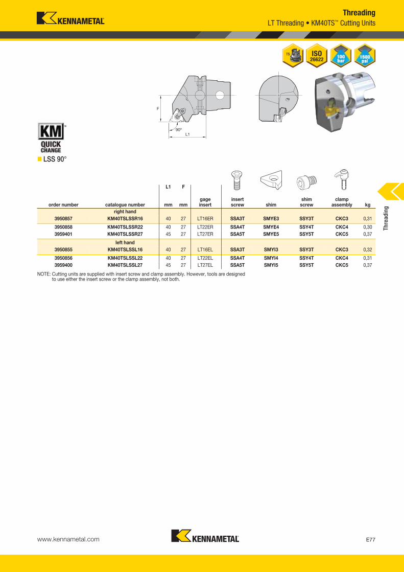
www.kennametal.com E77
ThreadingLT Threading • KM40TS™ Cutting Units
� LSS 90°
NOTE: Cutting units are supplied with insert screw and clamp assembly. However, tools are designed to use either the insert screw or the clamp assembly, not both.
L1 F
order number catalogue number mm mmgageinsert
insert screw shim
shim screw
clamp assembly kg
right hand3950857 KM40TSLSSR16 40 27 LT16ER SSA3T SMYE3 SSY3T CKC3 0,31
3950858 KM40TSLSSR22 40 27 LT22ER SSA4T SMYE4 SSY4T CKC4 0,303959401 KM40TSLSSR27 45 27 LT27ER SSA5T SMYE5 SSY5T CKC5 0,37
left hand3950855 KM40TSLSSL16 40 27 LT16EL SSA3T SMYI3 SSY3T CKC3 0,32
3950856 KM40TSLSSL22 40 27 LT22EL SSA4T SMYI4 SSY4T CKC4 0,313959400 KM40TSLSSL27 45 27 LT27EL SSA5T SMYI5 SSY5T CKC5 0,37
Thre
adin
g
KM_Master12_Turning_E076_E077_Metric.qxp:Layout 1 3/6/12 2:16 PM Page E77
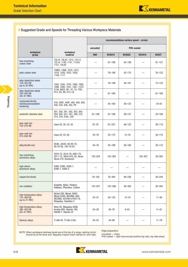
� Suggested Grade and Speeds for Threading Various Workpiece Materials
NOTE: When workpiece hardness levels are at the top of a range, starting m/minshould be at the lower end. Regularly inspect insert clamps for worn flats.
Edge preparation:Uncoated — sharpPVD coated — light hone except positive top rake, top rake-sharp
workpiece group
workpiece material
recommendations surface speed – m/min
uncoated PVD coated
K68 KC5010 KC5025 KC5410 KU25T
free-machiningcarbon steel
10L18, 10L45, 1213, 12L13,12L14, 1140, 1141, 11L44,1151, 10L50
— 91–198 45–198 — 91–137
plain carbon steel10063, 1008, 1010, 1015,1018, 1020, 1025, 1026,1108, 1117
— 76–198 45–175 — 76–122
alloy steels/tool steels150–325 HB(up to 35 HRC) 1042, 1045, 1070, 1080, 1085,
1090, 1095, 1541, 1561, 1572,5140, 8620, W1, O1, S1, P20,H13, D2, A6, H13, L6
— 76–198 38–167 — 73–122
alloy steels/tool steels330–450 HB(36–47 HRC)
— 61–160 — — 61–106
martensitic/ferriticstainless/precipitationhardening
416, 420F, 440F, 405, 409, 429,430, 434, 436, 442, PH — 45–160 30–122 — 24–61
austenitic stainless steel201, 202, 301, 302, 303, 304,304, 305, 321, 347, 348, 310,314, 316, 316L, 330
61–106 61–198 46–137 — 24–106
grey cast iron135–270 HB class 20, 30, 35, 45 61–91 61–237 46–122 — 30–110
grey cast iron275–450 HB class 50, 55, 60 45–76 45–175 15–76 — 30–110
alloy/ductile iron A536, J434C, 60-40-18,80-55-06, 100-70-03 45–76 45–198 30–160 — 30–110
free-machiningaluminium alloys
2024-T4, 2014-T6, 6061-T62011-T3, 3003-H18, A2, Alcan,Alcoa 510, Duralumin
122–244 122–365 — 152–457 30–305
high-siliconaluminium alloys
A380, A390, A380-1,A390-1, A380-2 — — — — —
copper/zinc/brass 76–183 76–304 46–236 — 30–244
non-metallics Graphite, Nylon, Plastics,Rubbers, Phenolics, Carbon 122–457 122–396 46–305 — 30–304
high-temperature alloys125–269 HB(up to 27 HRC)
Nickel 200, Monel, R405,Monel K500, INCONEL 600,INCONEL 625/901x750/718,Waspaloy, Hastelloy C
24–37 24–122 13–76 — 11–85
high-temperature alloys260–450 HB(26–47 HRC)
Rene 95, Waspaloy A286,Incoloy 800, Haynes 188,Stellite F, Haynes 25
24–30 30–76 6–61 — 11–61
titanium alloys Ti-6AI-4V, TI-5AI-2.5Sn 34–55 34–99 — — 11–76
www.kennametal.comE78
Grade Selection ChartTechnical Information
Thre
adin
g
KM_Master12_Turning_E078_E079_Metric.qxp:Layout 1 3/6/12 2:16 PM Page E78

www.kennametal.com E79
Technical InformationFailure and Solution Guide
� Tool Detective
• Use a more wear-resistant grade (e.g., KC5025).• Increase coolant flow.• Check the centerline height of the tool.
(The smaller the diameter, the more criticalthe need for centerline accuracy.)
• Use a more wear-resistant grade (e.g., KC5010™).• Reduce m/min.• Alter infeed method/angle.• Increase coolant flow.
• Minimise tool overhang.• Check for workpiece deflection.• Adjust m/min.• Check insert and clamp.• Use modified feed angle.• Verify that tool cutting position is at workpiece centerline.• Adjust hone level by ordering special insert.
• Use positive rake or full profile insert.• Increase coolant concentration.• Alter infeed.• Increases m/min.• Check machine “Z” travel axis.• Check insert form.• Check for correct shim in LT system.
possible solution
• Increase m/min.• Increase coolant concentration and/or flow.• Adjust infeed angle.• Increase depth of cut per pass.• Adjust hone level by ordering special insert.
• Alter infeed to modified flank.• Adjust chip load.• Increase or decrease number of passes.• Eliminate spring passes.• Use tougher grade (e.g., KC5025™).• Increase m/min if chipping on trailing edge.• Decrease m/min if chipping on leading edge.• Minimise tool overhang.• Check for insert movement/check clamp.• Check for possible part deflection.• Adjust hone size by ordering special insert.
• Decrease chip load.• Use large nose radius if allowable.• Use tougher grade (e.g., KC5025).• Alter infeed to modified flank.• Adjust hone size by ordering special insert.
thread with torn finish
• Wrong grade.• Insufficient coolant.• Off centerline.
• Wrong grade.• Speed too high.• Improper infeed angle.• Insufficient coolant.
• Poor rigidity.• Incorrect speed.• Insert movement.• Improper infeed.• Off centerline.• Wrong edge prep.
• Burrs.• Torn finish.• Steps.
• Speed too low.• Insufficient coolant.• Chip load.• Wrong edge prep.
• Improper infeed.• Chip load.• Wrong grade.• Incorrect speed.• Poor rigidity.• Wrong edge prep.
• Heavy chip load.• Small nose radius.• Wrong grade.• Improper infeed.• Wrong edge prep.
causeproblem
chatter
built-up edge
deformation
chipping
broken nose
flank wear
Thre
adin
g
KM_Master12_Turning_E078_E079_Metric.qxp:Layout 1 3/6/12 2:16 PM Page E79
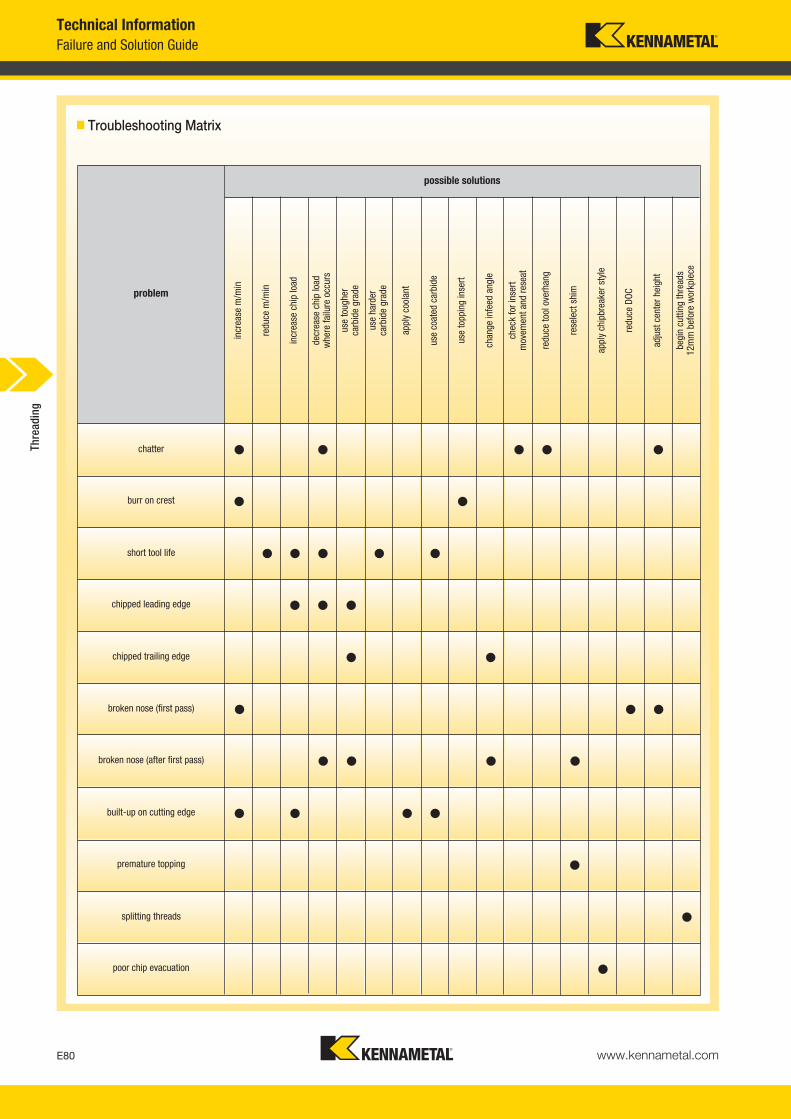
www.kennametal.comE80
Failure and Solution GuideTechnical Information
� Troubleshooting Matrix
possible solutions
problem
incr
ease
m/m
in
redu
ce m
/min
incr
ease
chi
p lo
ad
decr
ease
chi
p lo
ad
whe
re fa
ilure
occ
urs
use
toug
her
carb
ide
grad
e
use
hard
erca
rbid
e gr
ade
appl
y co
olan
t
use
coat
ed c
arbi
de
use
topp
ing
inse
rt
chan
ge in
feed
ang
le
chec
k fo
r ins
ert
mov
emen
t and
rese
at
redu
ce to
ol o
verh
ang
rese
lect
shi
m
appl
y ch
ipbr
eake
r sty
le
redu
ce D
OC
adju
st c
ente
r hei
ght
begi
n cu
tting
thre
ads
12m
m b
efor
e w
orkp
iece
• • • • •chatter
• •burr on crest
• • • • •short tool life
• • •chipped leading edge
• •chipped trailing edge
• • •broken nose (first pass)
• • • •broken nose (after first pass)
• • • •built-up on cutting edge
•premature topping
•splitting threads
•poor chip evacuation
Thre
adin
g
KM_Master12_Turning_E080_E081_Metric.qxp:Layout 1 3/27/12 8:02 AM Page E80
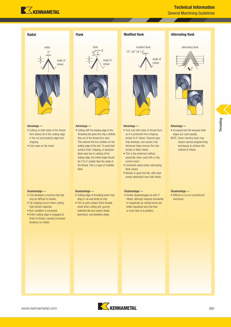
www.kennametal.com E81
Technical InformationGeneral Machining Guidelines
Radial
Advantage —
• Cutting on both sides of the threadform places all of the cutting edge in the cut and protects edge fromchipping.
• Even wear on the insert.
Flank
Advantage —
• Cutting with the leading edge of thethreading tool gives the chip a definiteflow out of the thread form area. This reduces the burr problem on thetrailing edge of the tool. To avoid badsurface finish, chipping, or excessiveflank wear due to rubbing of thetrailing edge, the infeed angle shouldbe 3˚ to 5˚ smaller than the angle ofthe thread. This is a type of modifiedflank.
Modified flank
Advantage —
• Tool cuts both sides of thread form, so it is protected from chippingsimilar to 0˚ infeed. Channel-type chip develops, but uneven chipthickness helps remove the chipsimilar to flank infeed.
• This is the preferred method,especially when used with a chipcontrol insert.
• Combined radial and/or alternatingflank infeed.
• Results in good tool life, with wearevenly distributed over both flanks.
Alternating flank
Advantage —
• Increased tool life because bothedges are used equally.
NOTE: Some machine tools mayrequire special programmingtechniques to achieve thismethod of infeed.
radial
angle ofinfeed
flank
angle ofinfeed
30°0°
modified flank
angle ofinfeed
15°–29° 29 1/2'
alternating flank
Disadvantage —• Tool develops a channel chip that
may be difficult to handle.• Tip chipping occurs when cutting
high-tensile materials.• Burr condition is increased.• Entire cutting edge is engaged at
finish of thread, causing increasedtendency to chatter.
Disadvantage —• Trailing edge of threading insert may
drag or rub and tends to chip.• Torn or poor surface finish threads
result when cutting soft, gummymaterials like low-carbon steels,aluminium, and stainless steels.
Disadvantage —• Similar disadvantages as with 0˚
infeed, although reduced somewhatin magnitude as cutting forces arebetter equalised and chip flow is much less of a problem.
Disadvantage —• Difficult to cut on conventional
machinery.
Thre
adin
g
KM_Master12_Turning_E080_E081_Metric.qxp:Layout 1 3/27/12 8:02 AM Page E81
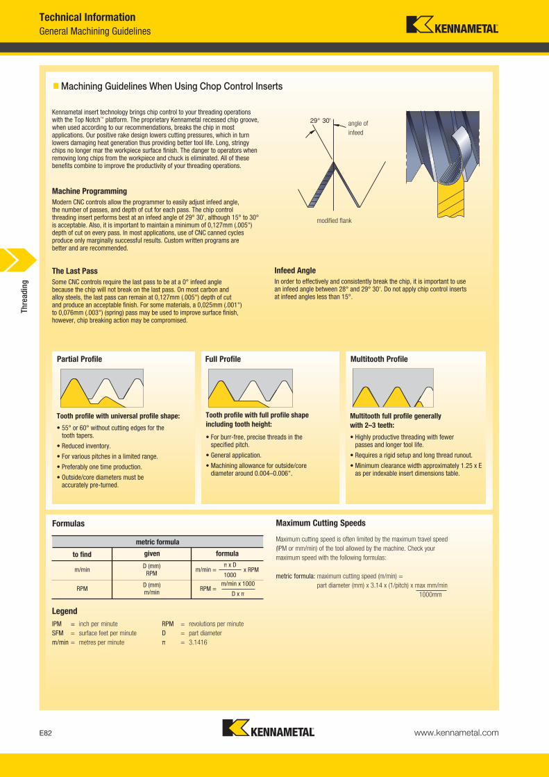
www.kennametal.comE82
General Machining GuidelinesTechnical Information
� Machining Guidelines When Using Chop Control Inserts
Kennametal insert technology brings chip control to your threading operations with the Top Notch™ platform. The proprietary Kennametal recessed chip groove,when used according to our recommendations, breaks the chip in mostapplications. Our positive rake design lowers cutting pressures, which in turnlowers damaging heat generation thus providing better tool life. Long, stringychips no longer mar the workpiece surface finish. The danger to operators whenremoving long chips from the workpiece and chuck is eliminated. All of thesebenefits combine to improve the productivity of your threading operations.
Machine ProgrammingModern CNC controls allow the programmer to easily adjust infeed angle, the number of passes, and depth of cut for each pass. The chip control threading insert performs best at an infeed angle of 29° 30', although 15° to 30°is acceptable. Also, it is important to maintain a minimum of 0,127mm (.005")depth of cut on every pass. In most applications, use of CNC canned cyclesproduce only marginally successful results. Custom written programs are better and are recommended.
The Last PassSome CNC controls require the last pass to be at a 0° infeed angle because the chip will not break on the last pass. On most carbon and alloy steels, the last pass can remain at 0,127mm (.005") depth of cut and produce an acceptable finish. For some materials, a 0,025mm (.001") to 0,076mm (.003") (spring) pass may be used to improve surface finish,however, chip breaking action may be compromised.
Infeed AngleIn order to effectively and consistently break the chip, it is important to use an infeed angle between 28° and 29° 30'. Do not apply chip control inserts at infeed angles less than 15°.
modified flank
angle ofinfeed
Formulas
metric formula
to find given formula
m/minD (mm)
RPM
RPMD (mm)m/min
m/min =π x D
1000x RPM
RPM =
Maximum cutting speed is often limited by the maximum travel speed (IPM or mm/min) of the tool allowed by the machine. Check your maximum speed with the following formulas:
metric formula: maximum cutting speed (m/min) =part diameter (mm) x 3.14 x (1/pitch) x max mm/min
1000mm
Maximum Cutting Speeds
IPM = inch per minuteSFM = surface feet per minutem/min = metres per minute
RPM = revolutions per minuteD = part diameterπ = 3.1416
Legend
Partial Profile
Tooth profile with universal profile shape:
• 55° or 60° without cutting edges for the tooth tapers.
• Reduced inventory.
• For various pitches in a limited range.
• Preferably one time production.
• Outside/core diameters must be accurately pre-turned.
Full Profile
Tooth profile with full profile shapeincluding tooth height:
• For burr-free, precise threads in the specified pitch.
• General application.
• Machining allowance for outside/core diameter around 0.004–0.006".
Multitooth Profile
Multitooth full profile generally with 2–3 teeth:
• Highly productive threading with fewer passes and longer tool life.
• Requires a rigid setup and long thread runout.
• Minimum clearance width approximately 1.25 x Eas per indexable insert dimensions table.
m/min x 1000
D x π
Thre
adin
g
KM_Master12_Turning_E082_E083_Metric.qxp:Layout 1 3/27/12 8:50 AM Page E82
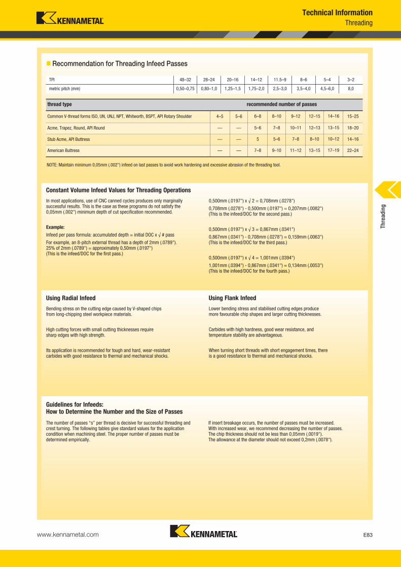
www.kennametal.com E83
Technical InformationThreading
� Recommendation for Threading Infeed Passes
Guidelines for Infeeds:How to Determine the Number and the Size of Passes
0,500mm (.0197") x √ 2 = 0,708mm (.0278")
0,708mm (.0278") - 0,500mm (.0197") = 0,207mm (.0082")(This is the infeed/DOC for the second pass.)
0,500mm (.0197") x √ 3 = 0,867mm (.0341")
0,867mm (.0341") - 0,708mm (.0278") = 0,159mm (.0063")(This is the infeed/DOC for the third pass.)
0,500mm (.0197") x √ 4 = 1,001mm (.0394")
1,001mm (.0394") - 0,867mm (.0341") = 0,134mm (.0053")(This is the infeed/DOC for the fourth pass.)
In most applications, use of CNC canned cycles produces only marginallysuccessful results. This is the case as these programs do not satisfy the 0,05mm (.002") minimum depth of cut specification recommended.
Example:
Infeed per pass formula: accumulated depth = initial DOC x √ # pass
For example, an 8-pitch external thread has a depth of 2mm (.0789"). 25% of 2mm (.0789") = approximately 0,50mm (.0197") (This is the infeed/DOC for the first pass.)
Constant Volume Infeed Values for Threading Operations
thread type recommended number of passes
NOTE: Maintain minimum 0,05mm (.002") infeed on last passes to avoid work hardening and excessive abrasion of the threading tool.
Common V-thread forms ISO, UN, UNJ, NPT, Whitworth, BSPT, API Rotary Shoulder
Acme, Trapez, Round, API Round
Stub Acme, API Buttress
American Buttress
4–5 5–6 6–8 8–10 9–12 12–15 14–16 15–25
— — 5–6 7–8 10–11 12–13 13–15 18–20
— — 5 5–6 7–8 8–10 10–12 14–16
— — 7–8 9–10 11–12 13–15 17–19 22–24
Lower bending stress and stabilised cutting edges produce more favourable chip shapes and larger cutting thicknesses.
Carbides with high hardness, good wear resistance, and temperature stability are advantageous.
When turning short threads with short engagement times, there is a good resistance to thermal and mechanical shocks.
Using Flank Infeed
Bending stress on the cutting edge caused by V-shaped chips from long-chipping steel workpiece materials.
High cutting forces with small cutting thicknesses require sharp edges with high strength.
Its application is recommended for tough and hard, wear-resistant carbides with good resistance to thermal and mechanical shocks.
Using Radial Infeed
TPI 48–32 28–24 20–16 14–12 11.5–9 8–6 5–4 3–2
metric pitch (mm) 0,50–0,75 0,80–1,0 1,25–1,5 1,75–2,0 2,5–3,0 3,5–4,0 4,5–6,0 8,0
The number of passes “s” per thread is decisive for successful threading andcrest turning. The following tables give standard values for the applicationcondition when machining steel. The proper number of passes must bedetermined empirically.
If insert breakage occurs, the number of passes must be increased. With increased wear, we recommend decreasing the number of passes. The chip thickness should not be less than 0,05mm (.0019"). The allowance at the diameter should not exceed 0,2mm (.0078").
Thre
adin
g
KM_Master12_Turning_E082_E083_Metric.qxp:Layout 1 3/27/12 8:50 AM Page E83

www.kennametal.comE84
Threading Infeed TablesTechnical Information
Metric ISO, External Thread Cutting
Metric ISO, Internal Thread Cutting
thread pitch P (mm) 0,50 0,75 1,00 1,25 1,50 1,75 2,00 2,50 3,00 3,50 4,00 4,50 5,00
depth h1 0,307 0,460 0,613 0,767 0,920 1,074 1,227 1,534 1,840 2,147 2,454 2,760 3,067
numberof passes 4 4 5 6 6 8 8 10 12 14 15 15 16
values for flank infeed (X/Z)
orderof passes X/Z X/Z X/Z X/Z X/Z X/Z X/Z X/Z X/Z X/Z X/Z X/Z X/Z
1 0,117/- 0,176/- -0,195/- 0,206/- 0,248/- 0,216/- 0,247/- 0,238/- 0,223/- 0,204/- 0,205/- 0,231/- 0,226/-
2 0,078/0,045 0,118/0,068 0,140/0,081 0,160/0,092 0,192/0,111 0,194/0,112 0,222/0,128 0,248/0,143 0,272/0,157 0,294/0,170 0,324/0,187 0,362/0,211 0,391/0,227
3 0,060/0,035 0,090/0,052 0,108/0,062 0,123/0,071 0,147/0,085 0,149/0,986 0,170/0,098 0,190/0,110 0,209/0,120 0,225/0,130 0,249/0,144 0,280/0,162 0,301/0,174
4 0,052/0,029 0,076/0,044 0,090/0,052 0,104/0,060 0,124/0,072 0,126/0,073 0,144/0,083 0,161/0,093 0,176/0,102 0,190/0,110 0,210/0,121 0,236/0,136 0,254/0,147
5 0,080/0,046 0,091/0,053 0,110/0,063 0,111/0,064 0,126/0,073 0,141/0,082 0,155/0,089 0,167/0,097 0,185/0,107 0,236/0,136 0,224/0,129
6 0,083/0,048 0,099/0,057 0,100/0,058 0,114/0,066 0,128/0,074 0,140/0,081 0,151/0,087 0,167/0,096 0,188/0,108 0,202/0,117
7 0,092/0,053 0,105/0,061 0,118/0,068 0,129/0,074 0,139/0,080 0,154/0,089 0,173/0,100 0,186/0,107
8 0,087/0,049 0,098/0,057 0,109/0,063 0,120/0,069 0,129/0,075 0,143/0,083 0,161/0,093 0,173/0,100
9 0,103/0,059 0,113/0,065 0,122/0,070 0,134/0,078 0,151/0,087 0,163/0,094
10 0,098/0,056 0,106/0,061 0,115/0,066 0,127/0,073 0,143/0,082 0,154/0,089
11 0,101/0,058 0,109/0,063 0,121/0,070 0,136/0,078 0,146/0,084
12 0,097/0,056 0,105/0,060 0,115/0,067 0,130/0,075 0,140/0,081
13 0,100/0,058 0,111/0,064 0,125/0,072 0,134/0,077
14 0,097/0,056 0,107/0,061 0,120/0,069 0,129/0,074
15 0,102/0,059 0,116/0,067 0,124/0,072
16 0,120/0,069
thread pitch P (mm) 0,50 0,75 1,00 1,25 1,50 1,75 2,00 2,50 3,00 3,50 4,00 4,50 5,00
depth h1 0,271 0,406 0,541 0,677 0,812 0,947 1,083 1,353 1,624 1,894 2,165 2,436 2,706
numberof passes 4 4 5 6 6 8 8 10 11 12 14 15 16
values for flank infeed (X/Z)
orderof passes X/Z X/Z X/Z X/Z X/Z X/Z X/Z X/Z X/Z X/Z X/Z X/Z X/Z
1 0,108/- 0,162/- 0,182/- 0,196/- 0,235/- 0,212/- 0,243/- 0,243/- 0,263/- 0,277/- 0,261/- 0,269/- 0,277/-
2 0,067/0,039 0,102/0,058 0,120/0,069 0,137/0,079 0,165/0,095 0,166/0,096 0,190/0,110 0,213/0,123 0,243/0,140 0,272/0,157 0,288/0,166 0,313/0,180 0,336/0,194
3 0,052/0,030 0,077/0,045 0,092/0,053 0,105/0,061 0,126/0,073 0,128/0,074 0,146/0,084 0,163/0,094 0,187/0,108 0,209/0,120 0,221/0,127 0,240/0,138 0,258/0,149
4 0,044/0,025 0,065/0,038 0,078/0,045 0,089/0,051 0,107/0,062 0,108/0,062 0,123/0,071 0,138/0,079 0,157/0,091 0,176/0,102 0,186/0,107 0,202/0,117 0,218/0,126
5 0,069/0,040 0,078/0,045 0,94/0,054 0,095/0,055 0,108/0,063 0,121/0,070 0,139/0,080 0,155/0,089 0,164/0,095 0,178/0,103 0,192/0,111
6 0,072/0,041 0,085/0,049 0,086/0,050 0,098/0,057 0,110/0,063 0,125/0,072 0,140/0,081 0,148/0,086 0,161/0,093 0,173/0,100
7 0,079/0,046 0,090/0,052 0,101/0,058 0,115/0,067 0,129/0,074 0,136/0,079 0,148/0,086 0,159/0,092
8 0,073/0,042 0,084/0,048 0,094/0,054 0,107/0,062 0,120/0,069 0,127/0,073 0,138/0,080 0,148/0,086
9 0,088/0,051 0,101/0,058 0,113/0,065 0,119/0,069 0,129/0,075 0,139/0,080
10 0,082/0,048 0,095/0,055 0,106/0,061 0,113/0,065 0,122/0,071 0,132/0,076
11 0,092/0,052 0,101/0,058 0,107/0,062 0,116/0,067 0,125/0,072
12 0,097/0,056 0,102/0,059 0,111/0,064 0,120/0,069
13 0,098/0,057 0,107/0,062 0,115/0,066
14 0,095/0,055 0,103/0,059 0,111/0,064
15 0,099/0,057 0,107/0,062
16 0,107/0,062
Thre
adin
g
KM_Master12_Turning_E084_E085_Metric.qxp:Layout 1 3/6/12 2:17 PM Page E84

www.kennametal.com E85
Technical InformationThreading Infeed Tables
UN Thread, External Thread Cutting
UN Thread, Internal Thread Cutting
thread pitch TPI 24 20 18 16 14 12 11 10 9 8 7 6 5
depth h1 0,649 0,779 0,866 0,974 1,113 1,299 1,416 1,558 1,731 1,948 2,226 2,597 3,116
numberof passes 5 6 6 7 9 9 10 11 12 13 14 15 16
values for flank infeed (X/Z)
orderof passes X/Z X/Z X/Z X/Z X/Z X/Z X/Z X/Z X/Z X/Z X/Z X/Z X/Z
1 0,206/- 0,210/- 0,233/- 0,226/- 0,196/- 0,229/- 0,220/- 0,214/- 0,210/- 0,211/- 0,213/- 0,218/- 0,229/-
2 0,148/0,086 0,163/0,094 0,181/0,104 0,188/0,109 0,189/0,110 0,222/0,128 0,228/0,132 0,240/0,139 0,256/0,148 0,276/0,160 0,304/0,176 0,343/0,198 0,399/0,230
3 0,114/0,066 0,125/0,072 0,139/0,080 0,145/0,083 0,146/0,084 0,170/0,098 0,176/0,102 0,184/0,106 0,196/0,113 0,212/0,122 0,234/0,135 0,263/0,152 0,306/0,177
4 0,096/0,055 0,105/0,061 0,117/0,068 0,122/0,070 0,123/0,071 0,143/0,083 0,148/0,086 0,155/0,090 0,165/0,095 0,179/0,103 0,197/0,114 0,222/0,128 0,258/0,149
5 0,085/0,049 0,093/0,054 0,103/0,059 0,107/0,062 0,108/0,062 0,126/0,073 0,131/0,075 0,137/0,079 0,146/0,084 0,158/0,091 0,173/0,100 0,195/0,113 0,227/0,131
6 0,084/0,048 0,093/0,054 0,097/0,056 0,098/0,056 0,114/0,066 0,118/0,068 0,124/0,072 0,132/0,076 0,142/0,082 0,157/0,091 0,177/0,102 0,205/0,119
7 0,089/0,052 0,090/0,052 0,105/0,061 0,109/0,063 0,114/0,066 0,121/0,070 0,142/0,082 0,144/0,083 0,163/0,094 0,189/0,109
8 0,084/0,048 0,098/0,056 0,101/0,058 0,106/0,061 0,113/0,065 0,122/0,070 0,134/0,078 0,151/0,087 0,176/0,101
9 0,079/0,045 0,092/0,053 0,095/0,055 0,100/0,057 0,106/0,061 0,114/0,066 0,126/0,073 0,142/0,082 0,165/0,095
10 0,090/0,052 0,094/0,054 0,100/0,058 0,108/0,063 0,119/0,069 0,134/0,078 0,156/0,090
11 0,090/0,052 0,095/0,055 0,103/0,059 0,113/0,065 0,128/0,074 0,149/0,086
12 0,091/0,053 0,098/0,057 0,108/0,063 0,122/0,071 0,142/0,082
13 0,094/0,054 0,104/0,060 0,117/0,068 0,136/0,079
14 0,100/0,058 0,113/0,065 0,131/0,076
15 0,109/0,063 0,126/0,073
16 0,122/0,071
thread pitch TPI 24 20 18 16 14 12 11 10 9 8 7 6 5
depth h1 0,573 0,687 0,764 0,860 0,982 1,146 1,250 1,375 1,528 1,719 1,964 2,291 2,750
numberof passes 5 6 6 7 8 9 9 10 11 12 13 14 15
values for flank infeed (X/Z)
orderof passes X/Z X/Z X/Z X/Z X/Z X/Z X/Z X/Z X/Z X/Z X/Z X/Z X/Z
1 20,193/- 0,200/- 0,222/- 0,219/- 0,220/- 0,228/- 0,250/- 0,247/- 0,246/- 0,252/- 0,262/- 0,278/- 0,302/-
2 0,127/0,073 0,239/0,081 0,155/0,089 0,161/0,093 0,173/0,100 0,190/0,110 0,207/0,120 0,216/0,125 0,229/0,132 0,247/0,142 0,271/0,156 0,304/0,176 0,353/0,204
3 0,098/0,056 0,107/0,062 0,119/0,069 0,124/0,072 0,132/0,076 0,146/0,084 0,159/0,092 0,166/0,096 0,176/0,101 0,247/0,142 0,208/0,120 0,234/0,135 0,271/0,156
4 0,082/0,048 0,090/0,052 0,100/0,058 0,104/0,060 0,112/0,064 0,123/0,071 0,134/0,077 0,140/0,081 0,148/0,086 0,160/0,092 0,175/0,101 0,197/0,114 0,228/0,132
5 0,073/0,042 0,072/0,041 0,088/0,051 0,092/0,053 0,098/0,057 0,108/0,062 0,118/0,068 0,123/0,071 0,130/0,075 0,141/0,081 0,154/0,089 0,173/0,100 0,201/0,116
6 0,080/0,046 0,083/0,048 0,089/0,051 0,098/0,056 0,107/0,062 0,111/0,064 0,118/0,068 0,127/0,073 0,140/0,081 0,157/0,091 0,182/0,105
7 0,077/0,044 0,082/0,047 0,090/0,052 0,098/0,057 0,102/0,059 0,108/0,063 0,117/0,067 0,128/0,074 0,144/0,083 0,167/0,097
8 0,076/0,044 0,084/0,048 0,091/0,053 0,095/0,055 0,101/0,058 0,109/0,063 0,119/0,069 0,134/0,078 0,156/0,090
9 0,079/0,045 0,086/0,050 0,090/0,052 0,095/0,055 0,102/0,059 0,112/0,065 0,126/0,073 0,146/0,084
10 0,085/0,049 0,090/0,052 0,097/0,056 0,106/0,061 0,119/0,069 0,138/0,080
11 0,085/0,049 0,092/0,053 0,101/0,058 0,113/0,065 0,131/0,076
12 0,088/0,051 0,096/0,056 0,108/0,063 0,126/0,073
13 0,092/0,053 0,104/0,060 0,121/0,070
14 0,100/0,058 0,116/0,067
15 0,112/0,065
Thre
adin
g
KM_Master12_Turning_E084_E085_Metric.qxp:Layout 1 3/6/12 2:17 PM Page E85
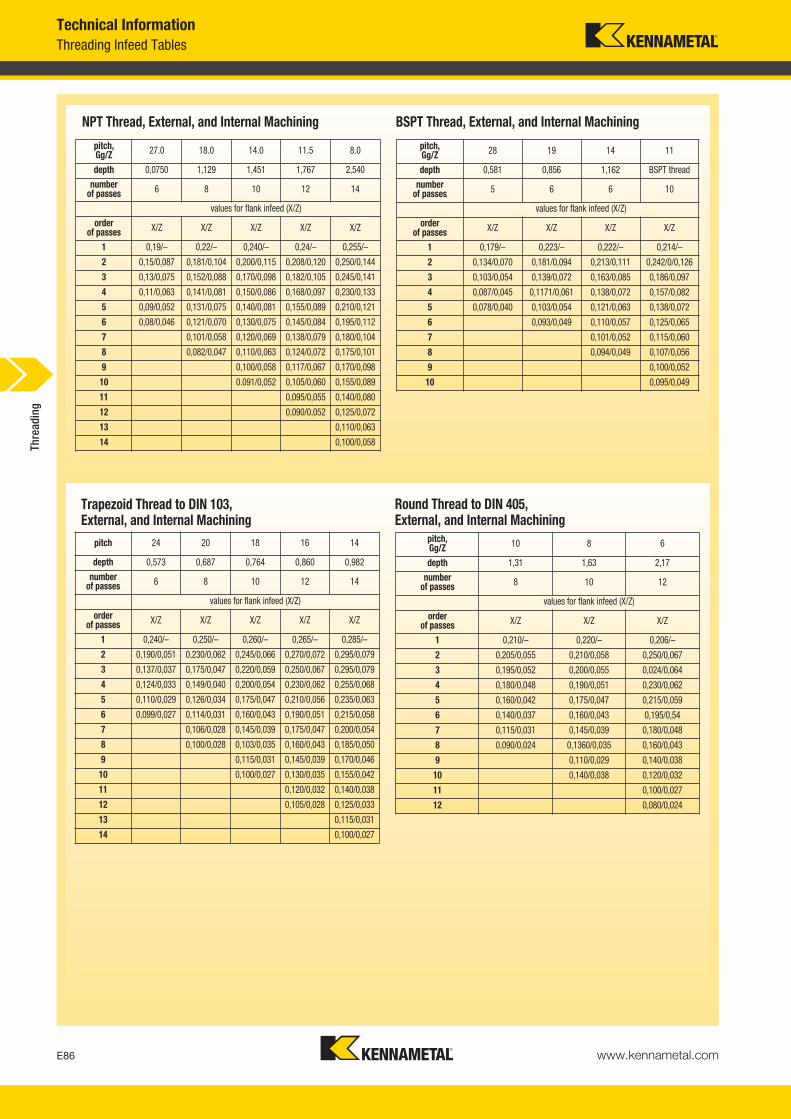
www.kennametal.comE86
Threading Infeed TablesTechnical Information
NPT Thread, External, and Internal Machining
Trapezoid Thread to DIN 103, External, and Internal Machining
BSPT Thread, External, and Internal Machining
Round Thread to DIN 405, External, and Internal Machining
pitch, Gg/Z 27.0 18.0 14.0 11.5 8.0
depth 0,0750 1,129 1,451 1,767 2,540
numberof passes 6 8 10 12 14
values for flank infeed (X/Z)
orderof passes X/Z X/Z X/Z X/Z X/Z
1 0,19/– 0,22/– 0,240/– 0,24/– 0,255/–
2 0,15/0,087 0,181/0,104 0,200/0,115 0,208/0,120 0,250/0,144
3 0,13/0,075 0,152/0,088 0,170/0,098 0,182/0,105 0,245/0,141
4 0,11/0,063 0,141/0,081 0,150/0,086 0,168/0,097 0,230/0,133
5 0,09/0,052 0,131/0,075 0,140/0,081 0,155/0,089 0,210/0,121
6 0,08/0,046 0,121/0,070 0,130/0,075 0,145/0,084 0,195/0,112
7 0,101/0,058 0,120/0,069 0,138/0,079 0,180/0,104
8 0,082/0,047 0,110/0,063 0,124/0,072 0,175/0,101
9 0,100/0,058 0,117/0,067 0,170/0,098
10 0.091/0,052 0,105/0,060 0,155/0,089
11 0,095/0,055 0,140/0,080
12 0,090/0,052 0,125/0,072
13 0,110/0,063
14 0,100/0,058
pitch, Gg/Z 28 19 14 11
depth 0,581 0,856 1,162 BSPT thread
numberof passes 5 6 6 10
values for flank infeed (X/Z)
orderof passes X/Z X/Z X/Z X/Z
1 0,179/– 0,223/– 0,222/– 0,214/–
2 0,134/0,070 0,181/0,094 0,213/0,111 0,242/0/0,126
3 0,103/0,054 0,139/0,072 0,163/0,085 0,186/0,097
4 0,087/0,045 0,1171/0,061 0,138/0,072 0,157/0,082
5 0,078/0,040 0,103/0,054 0,121/0,063 0,138/0,072
6 0,093/0,049 0,110/0,057 0,125/0,065
7 0,101/0,052 0,115/0,060
8 0,094/0,049 0,107/0,056
9 0,100/0,052
10 0,095/0,049
pitch 24 20 18 16 14
depth 0,573 0,687 0,764 0,860 0,982
numberof passes 6 8 10 12 14
values for flank infeed (X/Z)
orderof passes X/Z X/Z X/Z X/Z X/Z
1 0,240/– 0,250/– 0,260/– 0,265/– 0,285/–
2 0,190/0,051 0,230/0,062 0,245/0,066 0,270/0,072 0,295/0,079
3 0,137/0,037 0,175/0,047 0,220/0,059 0,250/0,067 0,295/0,079
4 0,124/0,033 0,149/0,040 0,200/0,054 0,230/0,062 0,255/0,068
5 0,110/0,029 0,126/0,034 0,175/0,047 0,210/0,056 0,235/0,063
6 0,099/0,027 0,114/0,031 0,160/0,043 0,190/0,051 0,215/0,058
7 0,106/0,028 0,145/0,039 0,175/0,047 0,200/0,054
8 0,100/0,028 0,103/0,035 0,160/0,043 0,185/0,050
9 0,115/0,031 0,145/0,039 0,170/0,046
10 0,100/0,027 0,130/0,035 0,155/0,042
11 0,120/0,032 0,140/0,038
12 0,105/0,028 0,125/0,033
13 0,115/0,031
14 0,100/0,027
pitch, Gg/Z 10 8 6
depth 1,31 1,63 2,17
numberof passes 8 10 12
values for flank infeed (X/Z)
orderof passes X/Z X/Z X/Z
1 0,210/– 0,220/– 0,206/–
2 0,205/0,055 0,210/0,058 0,250/0,067
3 0,195/0,052 0,200/0,055 0,024/0,064
4 0,180/0,048 0,190/0,051 0,230/0,062
5 0,160/0,042 0,175/0,047 0,215/0,059
6 0,140/0,037 0,160/0,043 0,195/0,54
7 0,115/0,031 0,145/0,039 0,180/0,048
8 0,090/0,024 0,1360/0,035 0,160/0,043
9 0,110/0,029 0,140/0,038
10 0,140/0,038 0,120/0,032
11 0,100/0,027
12 0,080/0,024
Thre
adin
g
KM_Master12_Turning_E086_E087_Metric.qxp:Layout 1 3/6/12 2:17 PM Page E86
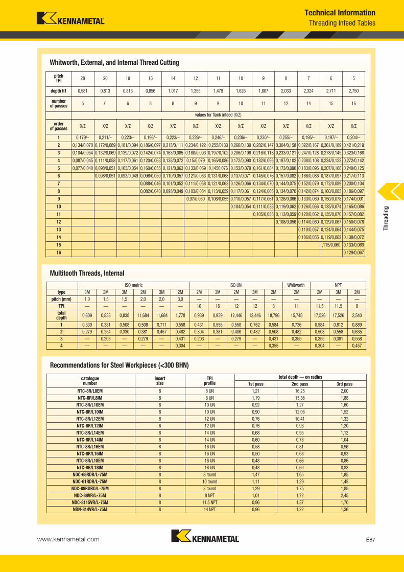
www.kennametal.com E87
Technical InformationThreading Infeed Tables
Whitworth, External, and Internal Thread Cutting
Multitooth Threads, Internal
ISO metric ISO UN Whitworth NPTtype 3M 2M 3M 2M 3M 2M 2M 3M 2M 3M 2M 2M 2M 3M 2M
pitch (mm) 1,0 1,5 1,5 2,0 2,0 3,0 — — — — — — — — —TPI — — — — — — 16 16 12 12 8 11 11.5 11.5 8
total depth 0,609 0,838 0,838 11,684 11,684 1,778 0,939 0,939 12,446 12,446 18,796 15,748 17,526 17,526 2,540
1 0,330 0,381 0,508 0,508 0,711 0,558 0,431 0,558 0,558 0,762 0,584 0,736 0,584 0,812 0,8892 0,279 0,254 0,330 0,381 0,457 0,482 0,304 0,381 0,406 0,482 0,508 0,482 0,508 0,558 0,6353 — 0,203 — 0,279 — 0,431 0,203 — 0,279 — 0,431 0,355 0,355 0,381 0,5584 — — — — — 0,304 — — — — 0,355 — 0,304 — 0,457
total depth — on radiuscatalogue number
insert size
TPI profile 1st pass 2nd pass 3rd pass
NTC-8R/L8EM 8 8 UN 1,21 16,25 2,00NTC-8R/L8IM 8 8 UN 1,19 15,36 1,88
NTC-8R/L10EM 8 10 UN 0,92 1,27 1,60NTC-8R/L10IM 8 10 UN 0,90 12,06 1,52NTC-8R/L12EM 8 12 UN 0,76 10,41 1,32NTC-8R/L12IM 8 12 UN 0,76 0,93 1,20NTC-8R/L14EM 8 14 UN 0,68 0,95 1,12NTC-8R/L14IM 8 14 UN 0,60 0,78 1,04NTC-8R/L16EM 8 16 UN 0,58 0,81 0,96NTC-8R/L16IM 8 16 UN 0,50 0,68 0,93NTC-8R/L18EM 8 18 UN 0,48 0,66 0,86NTC-8R/L18IM 8 18 UN 0,48 0,60 0,83
NDC-68RDR/L-75M 8 8 round 1,47 1,65 1,85NDC-61RDR/L-75M 8 10 round 1,11 1,29 1,45
NDC-88RDRD/L-75M 8 8 round 1,29 1,75 1,85NDC-88VR/L-75M 8 8 NPT 1,01 1,72 2,45
NDC-8115VR/L-75M 8 11.5 NPT 0,96 1,37 1,70NDN-814VR/L-75M 8 14 NPT 0,96 1,22 1,36
Recommendations for Steel Workpieces (<300 BHN)
pitch TPI 28 20 19 16 14 12 11 10 9 8 7 6 5
depth h1 0,581 0,813 0,813 0,856 1,017 1,355 1,479 1,626 1,807 2,033 2,324 2,711 2,750
numberof passes 5 6 6 8 8 9 9 10 11 12 14 15 16
values for flank infeed (X/Z)
orderof passes X/Z X/Z X/Z X/Z X/Z X/Z X/Z X/Z X/Z X/Z X/Z X/Z X/Z
1 0,179/– 0,211/– 0,223/– 0,196/– 0,223/– 0,226/– 0,246/– 0,236/– 0,230/– 0,255/– 0,195/– 0,197/– 0,204/–
2 0,134/0,070 0,172/0,089 0,181/0,094 0,186/0,097 0,213/0,111 0,234/0,122 0,255/0133 0,266/0,139 0,282/0,147 0,304/0,158 0,322/0,167 0,361/0,189 0,421/0,219
3 0,104/0,054 0,132/0,069 0,139/0,072 0,142/0,074 0,163/0,085 0,180/0,093 0,197/0,102 0,206/0,106 0,216/0,113 0,233/0,121 0,247/0,128 0,278/0,145 0,323/0,168
4 0,087/0,045 0,111/0,058 0,117/0,061 0,120/0,063 0,138/0,072 0,15/0,079 0,165/0,086 0,172/0,090 0,182/0,095 0,197/0,102 0,208/0,108 0,234/0,122 0,272/0,142
5 0,077/0,040 0,098/0,051 0,103/0,054 0,160/0,055 0,121/0,063 0,133/0,069 0,1450,076 0,152/0,079 0,161/0,084 0,173/0,090 0,183/0,095 0,207/0,108 0,240/0,125
6 0,098/0,051 0,093/0,049 0,096/0,050 0,110/0,057 0,121/0,063 0,131/0,068 0,137/0,071 0,145/0,076 0,157/0,082 0,166/0,086 0,187/0,097 0,217/0,113
7 0,088/0,046 0,101/0,052 0,111/0,058 0,121/0,063 0,126/0,066 0,134/0,070 0,144/0,075 0,152/0,079 0,172/0,089 0,200/0,104
8 0,082/0,043 0,093/0,049 0,103/0,054 0,113/0,059 0,117/0,061 0,124/0,065 0,134/0,070 0,142/0,074 0,160/0,083 0,186/0,097
9 0,97/0,050 0,106/0,055 0,110/0,057 0,117/0,061 0,126/0,066 0,133/0,069 0,150/0,078 0,174/0,091
10 0,104/0,054 0,111/0,058 0,119/0,062 0,126/0,066 0,135/0,074 0,165/0,086
11 0,105/0,055 0,113/0,059 0,120/0,062 0,135/0,070 0,157/0,082
12 0,108/0,056 0,114/0,060 0,129/0,067 0,150/0,078
13 0,110/0,057 0,124/0,064 0,144/0,075
14 0,106/0,055 0,119/0,062 0,138/0,072
15 ,115/0,060 0,133/0,069
16 0,129/0,067
Thre
adin
g
KM_Master12_Turning_E086_E087_Metric.qxp:Layout 1 3/6/12 2:17 PM Page E87
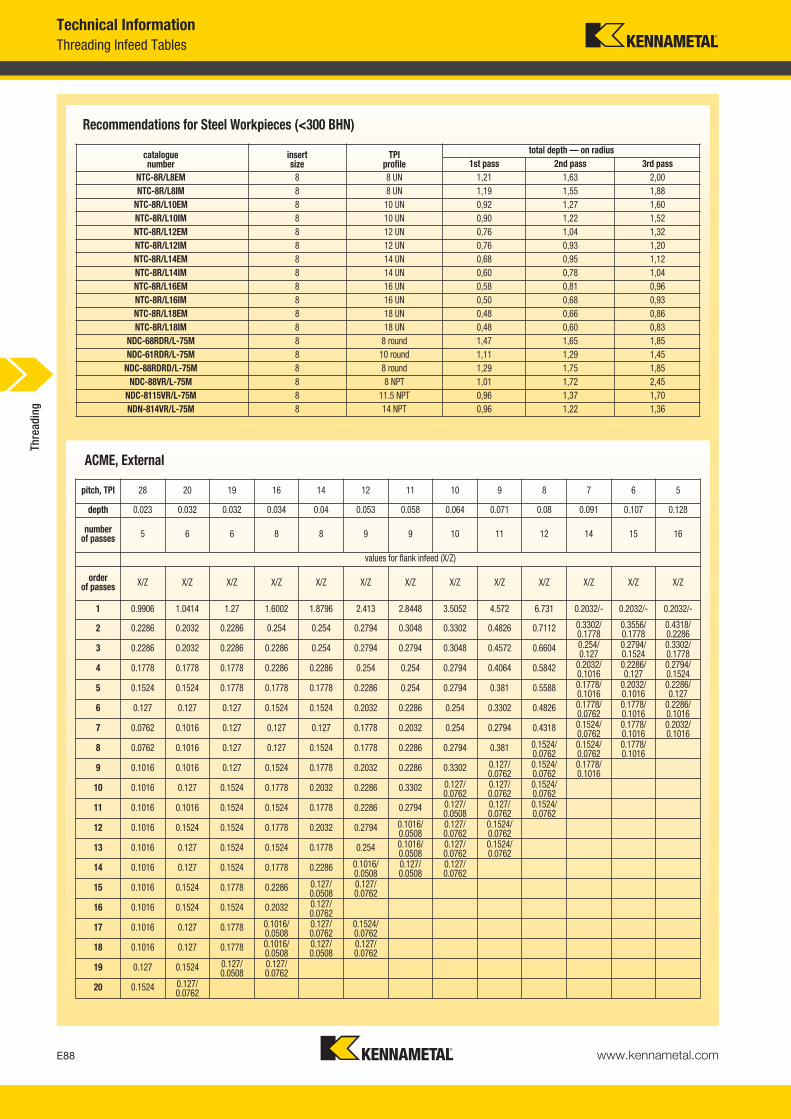
www.kennametal.comE88
Threading Infeed TablesTechnical Information
total depth — on radiuscatalogue number
insert size
TPI profile 1st pass 2nd pass 3rd pass
NTC-8R/L8EM 8 8 UN 1,21 1,63 2,00NTC-8R/L8IM 8 8 UN 1,19 1,55 1,88
NTC-8R/L10EM 8 10 UN 0,92 1,27 1,60NTC-8R/L10IM 8 10 UN 0,90 1,22 1,52NTC-8R/L12EM 8 12 UN 0,76 1,04 1,32NTC-8R/L12IM 8 12 UN 0,76 0,93 1,20NTC-8R/L14EM 8 14 UN 0,68 0,95 1,12NTC-8R/L14IM 8 14 UN 0,60 0,78 1,04NTC-8R/L16EM 8 16 UN 0,58 0,81 0,96NTC-8R/L16IM 8 16 UN 0,50 0,68 0,93NTC-8R/L18EM 8 18 UN 0,48 0,66 0,86NTC-8R/L18IM 8 18 UN 0,48 0,60 0,83
NDC-68RDR/L-75M 8 8 round 1,47 1,65 1,85NDC-61RDR/L-75M 8 10 round 1,11 1,29 1,45
NDC-88RDRD/L-75M 8 8 round 1,29 1,75 1,85NDC-88VR/L-75M 8 8 NPT 1,01 1,72 2,45
NDC-8115VR/L-75M 8 11.5 NPT 0,96 1,37 1,70NDN-814VR/L-75M 8 14 NPT 0,96 1,22 1,36
Recommendations for Steel Workpieces (<300 BHN)
ACME, External
pitch, TPI 28 20 19 16 14 12 11 10 9 8 7 6 5
depth 0.023 0.032 0.032 0.034 0.04 0.053 0.058 0.064 0.071 0.08 0.091 0.107 0.128
numberof passes 5 6 6 8 8 9 9 10 11 12 14 15 16
values for flank infeed (X/Z)
orderof passes X/Z X/Z X/Z X/Z X/Z X/Z X/Z X/Z X/Z X/Z X/Z X/Z X/Z
1 0.9906 1.0414 1.27 1.6002 1.8796 2.413 2.8448 3.5052 4.572 6.731 0.2032/- 0.2032/- 0.2032/-
2 0.2286 0.2032 0.2286 0.254 0.254 0.2794 0.3048 0.3302 0.4826 0.7112 0.3302/0.1778
0.3556/0.1778
0.4318/0.2286
3 0.2286 0.2032 0.2286 0.2286 0.254 0.2794 0.2794 0.3048 0.4572 0.6604 0.254/0.127
0.2794/0.1524
0.3302/0.1778
4 0.1778 0.1778 0.1778 0.2286 0.2286 0.254 0.254 0.2794 0.4064 0.5842 0.2032/0.1016
0.2286/0.127
0.2794/0.1524
5 0.1524 0.1524 0.1778 0.1778 0.1778 0.2286 0.254 0.2794 0.381 0.5588 0.1778/0.1016
0.2032/0.1016
0.2286/0.127
6 0.127 0.127 0.127 0.1524 0.1524 0.2032 0.2286 0.254 0.3302 0.4826 0.1778/0.0762
0.1778/0.1016
0.2286/0.1016
7 0.0762 0.1016 0.127 0.127 0.127 0.1778 0.2032 0.254 0.2794 0.4318 0.1524/0.0762
0.1778/0.1016
0.2032/0.1016
8 0.0762 0.1016 0.127 0.127 0.1524 0.1778 0.2286 0.2794 0.381 0.1524/0.0762
0.1524/0.0762
0.1778/0.1016
9 0.1016 0.1016 0.127 0.1524 0.1778 0.2032 0.2286 0.3302 0.127/0.0762
0.1524/0.0762
0.1778/0.1016
10 0.1016 0.127 0.1524 0.1778 0.2032 0.2286 0.3302 0.127/0.0762
0.127/0.0762
0.1524/0.0762
11 0.1016 0.1016 0.1524 0.1524 0.1778 0.2286 0.2794 0.127/0.0508
0.127/0.0762
0.1524/0.0762
12 0.1016 0.1524 0.1524 0.1778 0.2032 0.2794 0.1016/0.0508
0.127/0.0762
0.1524/0.0762
13 0.1016 0.127 0.1524 0.1524 0.1778 0.254 0.1016/0.0508
0.127/0.0762
0.1524/0.0762
14 0.1016 0.127 0.1524 0.1778 0.2286 0.1016/0.0508
0.127/0.0508
0.127/0.0762
15 0.1016 0.1524 0.1778 0.2286 0.127/0.0508
0.127/0.0762
16 0.1016 0.1524 0.1524 0.2032 0.127/0.0762
17 0.1016 0.127 0.1778 0.1016/0.0508
0.127/0.0762
0.1524/0.0762
18 0.1016 0.127 0.1778 0.1016/0.0508
0.127/0.0508
0.127/0.0762
19 0.127 0.1524 0.127/0.0508
0.127/0.0762
20 0.1524 0.127/0.0762
Thre
adin
g
KM_Master12_Turning_E088_E089_Metric.qxp:Layout 1 3/27/12 8:55 AM Page E88

www.kennametal.com E89
Technical InformationThreading Infeed Tables
ACME, Internal
pitch, TPI 28 20 19 16 14 12 11 10 9 8 7 6 5
depth 0.023 0.032 0.032 0.034 0.04 0.053 0.058 0.064 0.071 0.08 0.091 0.107 0.128
numberof passes 5 6 6 8 8 9 9 10 11 12 14 15 16
values for flank infeed (X/Z)
orderof passes X/Z X/Z X/Z X/Z X/Z X/Z X/Z X/Z X/Z X/Z X/Z X/Z X/Z
1 0.9906 1.0414 1.27 1.6002 1.8796 2.413 2.8448 3.5052 4.572 6.731 0.2032/- 0.2032/- 0.2032/-
2 0.2286 0.2032 0.2286 0.254 0.254 0.2794 0.3048 0.3302 0.4826 0.7112 0.3302/0.1778
0.3556/0.1778
0.4318/0.2286
3 0.2286 0.2032 0.2286 0.2286 0.254 0.2794 0.2794 0.3048 0.4572 0.6604 0.254/0.127
0.2794/0.1524
0.3302/0.1778
4 0.1778 0.1778 0.1778 0.2286 0.2286 0.254 0.254 0.2794 0.4064 0.5842 0.2032/0.1016
0.2286/0.127
0.2794/0.1524
5 0.1524 0.1524 0.1778 0.1778 0.1778 0.2286 0.254 0.2794 0.381 0.5588 0.1778/0.1016
0.2032/0.1016
0.2286/0.127
6 0.127 0.127 0.127 0.1524 0.1524 0.2032 0.2286 0.254 0.3302 0.4826 0.1778/0.0762
0.1778/0.1016
0.2286/0.1016
7 0.0762 0.1016 0.127 0.127 0.127 0.1778 0.2032 0.254 0.2794 0.4318 0.1524/0.0762
0.1778/0.1016
0.2032/0.1016
8 0.0762 0.1016 0.127 0.127 0.1524 0.1778 0.2286 0.2794 0.381 0.1524/0.0762
0.1524/0.0762
0.1778/0.1016
9 0.1016 0.1016 0.127 0.1524 0.1778 0.2032 0.2286 0.3302 0.127/0.0762
0.1524/0.0762
0.1778/0.1016
10 0.1016 0.127 0.1524 0.1778 0.2032 0.2286 0.3302 0.127/0.0762
0.127/0.0762
0.1524/0.0762
11 0.1016 0.1016 0.1524 0.1524 0.1778 0.2286 0.2794 0.127/0.0508
0.127/0.0762
0.1524/0.0762
12 0.1016 0.1524 0.1524 0.1778 0.2032 0.2794 0.1016/0.0508
0.127/0.0762
0.1524/0.0762
13 0.1016 0.127 0.1524 0.1524 0.1778 0.254 0.1016/0.0508
0.127/0.0762
0.1524/0.0762
14 0.1016 0.127 0.1524 0.1778 0.2286 0.1016/0.0508
0.127/0.0508
0.127/0.0762
15 0.1016 0.1524 0.1778 0.2286 0.127/0.0508
0.127/0.0762
16 0.1016 0.1524 0.1524 0.2032 0.127/0.0762
17 0.1016 0.127 0.1778 0.1016/0.0508
0.127/0.0762
0.1524/0.0762
18 0.1016 0.127 0.1778 0.1016/0.0508
0.127/0.0508
0.127/0.0762
19 0.127 0.1524 0.127/0.0508
0.127/0.0762
20 0.1524 0.127/0.0762
Thre
adin
g
KM_Master12_Turning_E088_E089_Metric.qxp:Layout 1 3/27/12 8:55 AM Page E89

www.kennametal.comE90
Screw Thread DefinitionsTechnical Information
� Screw Thread Definitions
� LT Threading Toolholders
1. Major diameter — The largest diameter of a straight screw thread. This applies to both internal and external threads.
2. Pitch diameter — On a straight thread, it is the diameter which passesthrough the thread profiles at such points which make the thread width ofthe groove equal to one-half of the basic pitch. On a “perfect thread,” thisoccurs at the point where the widths of the thread and groove are equal.
3. Thread angle (included) — The included angle between the individualflanks of the thread form.
4. Minor diameter — The smallest diameter of a straight screw thread. This applies to both internal and external threads.
5. Lead angle — On a straight thread, the lead angle is the angle created by the helix of the thread at the pitch diameter with a plane perpendicular to the axis.
6. Lead — The distance a screw thread advances axially in one revolution. On a single start, the pitch and lead are identical. The lead is equal to thepitch times the number of starts.
7. Pitch — The distance from a point on a screw thread to a corresponding point on the next thread measured parallel to the thread axis.
8. Crest — The outer most surface of the thread form which joins the flanks.
9. Root — The inner most surface of the thread form which joins the flanks. NOTE: Threads per inch (TPI) not shown: The number of threads per inch measured axially.The terms pitch and TPI are often used interchangeably. TPI = 1/pitch
screw
thread angleincluded
root
crest
pitch
lead
lead anglemajor diameter
pitch diameter
minor diameter
nut
In all cases, the proper shim selection is important.
Kennametal toolholders are supplied with a shim for a 1,5° lead angle. Changethe shim if your thread is more than 1° different. For more details on propershim selections, see pages E101–E103.
insert screw
insert
shim
shim screw
insert
shim
clampassembly
shim screw
NOTE: For shims and shim kits, see pages E101–E103.
� LT Threading Shim Catalogue Numbering System
81-1/4 UNX 2 AThread
SizeThreadClass
Thread form, series, and tolerance formulation symbol
A =ExternalthreadB =Internalthread
LH (21)Thread Gaging
System
21 = 22 = Per ANSI B1.323 =
1 = Allowance andtolerance
2 = Allowance andtolerance
3 = Tolerance only4 = Interference fit
Number ofthreads per
inch
LH = Left-hand thread (threads areright hand unless specified)
Thre
adin
g
KM_Master12_Turning_E090_E091_Metric.qxp:Layout 1 3/6/12 2:17 PM Page E90
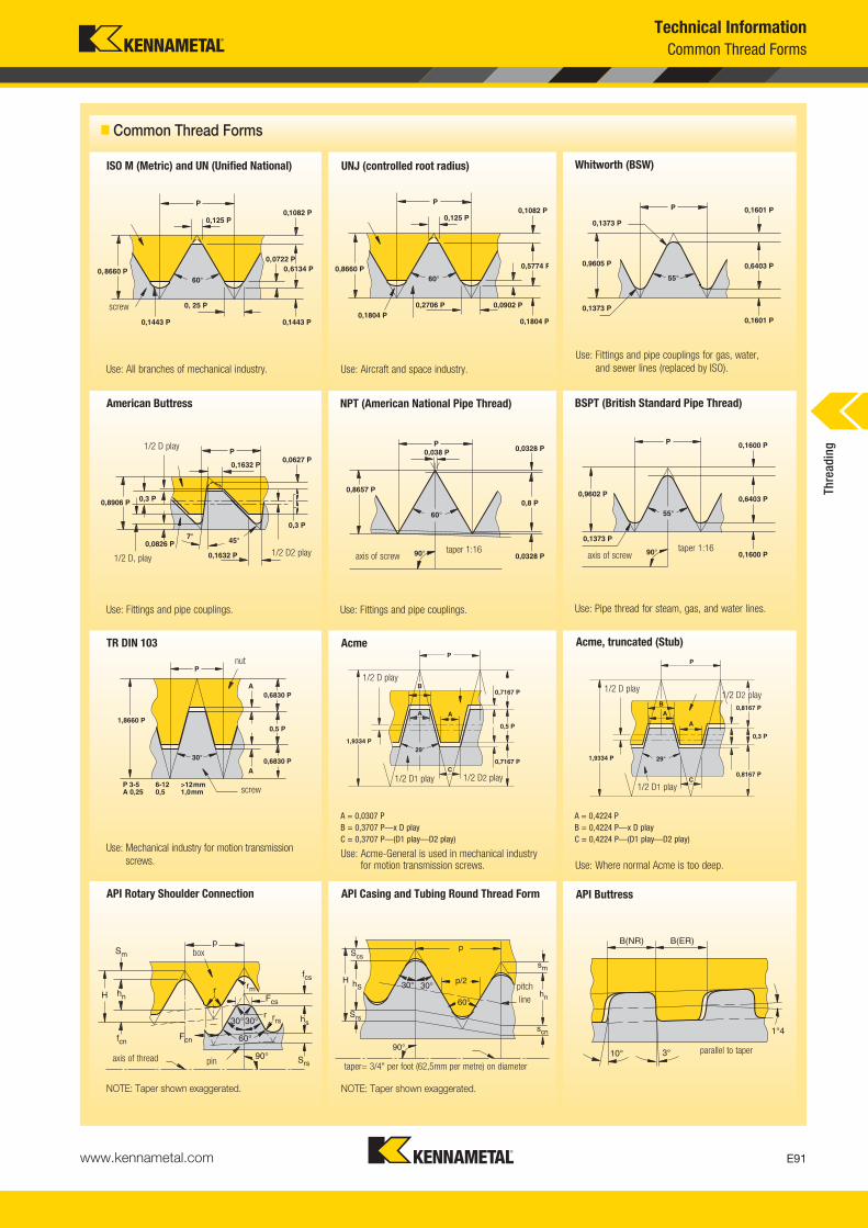
www.kennametal.com E91
Technical InformationCommon Thread Forms
� Common Thread Forms
screw
ISO M (Metric) and UN (Unified National)
Use: All branches of mechanical industry.
American Buttress
Use: Fittings and pipe couplings.
TR DIN 103
Use: Mechanical industry for motion transmissionscrews.
API Rotary Shoulder Connection
NOTE: Taper shown exaggerated.
UNJ (controlled root radius)
Use: Aircraft and space industry.
NPT (American National Pipe Thread)
Use: Fittings and pipe couplings.
Acme
Use: Acme-General is used in mechanical industry for motion transmission screws.
API Casing and Tubing Round Thread Form
NOTE: Taper shown exaggerated.
Whitworth (BSW)
Use: Fittings and pipe couplings for gas, water,and sewer lines (replaced by ISO).
BSPT (British Standard Pipe Thread)
Use: Pipe thread for steam, gas, and water lines.
Acme, truncated (Stub)
Use: Where normal Acme is too deep.
API Buttress
nut
screw
1/2 D play
1/2 D1 play 1/2 D2 play
1/2 D play
1/2 D1 play
1/2 D2 play
A = 0,0307 PB = 0,3707 P—x D playC = 0,3707 P—(D1 play—D2 play)
A = 0,4224 PB = 0,4224 P—x D playC = 0,4224 P—(D1 play—D2 play)
1/2 D play
1/2 D, play1/2 D2 play axis of screw
taper 1:16axis of screw
taper 1:16
parallel to taper
taper= 3/4" per foot (62,5mm per metre) on diameteraxis of thread pin
box
pitchline
Thre
adin
g
KM_Master12_Turning_E090_E091_Metric.qxp:Layout 1 3/6/12 2:17 PM Page E91

www.kennametal.comE92
Threading Selection Guide • Top Notch™
Technical Information
� Threading Method and Hand of Tooling
L
R
L
RL
R
L
R
L
R
L
R
L R
L R LR
L R
LR LR
external left-hand thread external right-hand thread internal left-hand thread internal right-hand thread
external right-hand thread external left-hand thread internal right-hand thread internal left-hand thread
hand of thread hand of toolholder hand of insert
L RRLRL
NOTE: Top Notch threading bars require opposite hand insert and clamp.Right-hand bar requires left-hand insert and clamp.Left-hand bar requires right-hand insert and clamp.
Required Information:
• External/internal operation.• Spindle rotation/hand of thread.• Feed direction.
Feed Direction Toward the Chuck • Standard Helix
Feed Direction Away from the Chuck • Reverse Helix
Thre
adin
g
KM_Master12_Turning_E092_E093_Metric.qxp:Layout 1 3/29/12 9:29 AM Page E92

www.kennametal.com E93
Technical InformationTop Notch™
Inch-Sized 60° V-Threading Limits
The following charts list the largest thread pitch that can be applied on internal applications using Top Notch threading inserts for 60° V-threading and Acme threading.
minimum minor diameter(minimum bore)
nominal thread size(maximum diameter)
*Twenty-four threads per inch and finer can be cut with an NT-2 insert providedthe minor diameter is 25mm or larger (11,18mm or larger with NT-1).
4** 3 2.7294-1/2** 2-7/8 2.634
5 2-3/4 2.5346 2-1/2 2.3207 2-1/4 2.0958 2 1.8659 1-15/16 1.817
10 1-7/8 1.76711 1-13/16 1.714
11-1/2 1-3/4 1.65612 1-3/4 1.66013 1-5/8 1.54214 1-9/16 1.48516* 1-7/16 1.370
TPInominal
thread sizeminimum
minor diameter (inch)
*Sixteen threads per inch and finer can be cut provided minor diameter is 34,8mm or larger.**NT-4 insert only.
internal threading limitationsNT-3, NT-4 V-threading inserts
6 1-7/8 — 1.695 —7 1-3/4 — 1.595 —8 1-5/8 — 1.490 —9 1-9/16 — 1.442 —
10 1-1/2 15/16 1.392 .83011 1-7/16 15/16 1.339 .830
11-1/2 1-3/8 15/16 1.281 .83012 1-3/8 9/16 1.285 .47213 1-5/16 9/16 1.229 .47214 1-1/4 9/16 1.173 .47216 1-1/4 9/16 1.182 .47218 1-1/8 9/16 1.065 .47220 1-1/8 1/2 1.071 .44024* 1-1/16 1/2 1.017 .440
TPI
nominal thread size
minimum minor diameter (inch)
NT-1 NT-2 NT-1 NT-2
internal threading limitationsNT-1, NT-2 V-threading inserts
Metric-sized 60° V-Threading Limits
*Thread pitch of 1mm and less can be cut with an NT-2 insert provided thecore thread diameter is 25mm or larger (11mm or larger with NT-1).
4,00 M48 x 4.00 — 43,67 —3,00 M42 x 3.00 — 38,75 —2,50 M39 x 2.50 M24 x 2,50 36,29 21,292,00 M33 x 2.00 M15 x 2,00 30,84 12,841,75 M32 x 1.75 M15 x 1,75 30,11 13,111,50 M32 x 1.50 M15 x 1,50 30,38 13,381,25 M29 x 1.29 M14 x 1,25 27,65 12,651,00* M27 x 1.00 M14 x 1,00 25,92 12,920,75 M22 x 0.75 M12 x 0,75 21,19 11,19
TPI
nominal thread size
minimum thread diameter (mm)
NT-1 NT-2 NT-1 NT-2
internal threading limitationsNT-1, NT-2 60° V-threading inserts
6,00** M76 x 6.00 69,505,50** M73 x 5.50 67,055,00 M70 x 5.00 64,594,00 M64 x 4.00 59,673,00 M52 x 3.00 48,752,50 M48 x 2.50 45,292,00 M42 x 2.00 39,841,75 M40 x 1.75 38,111,50* M38 x 1.50 36,38
TPnominal
thread sizeminimum
thread diameter (mm)
*Thread pitch of 1,5mm and less can be cut provided core thread diameter is 35mm or larger.**NT-4-insert only.
internal threading limitationsNT-3, NT-4 60° V-threading inserts
Acme Threading Limits
2** 5 4.500 114,32-1/2** 4-1/2 4.100 104,1
3** 4 3.665 93,14 3-1/2 3.250 82,65 3 2.800 71,16 2-1/2 2.333 59,38 2-1/4 2.125 54,0
10 2 1.900 48,312 1-3/4 1.667 42,414 1-5/8 1.554 39,516* 1-1/2 1.438 36,5
TPInominal
thread size
minimum thread diameter
*Sixteen threads per inch and finer can be cut provided minor diameter is 36,5mm (1.438") or larger.**NA-6 insert only.
internal threading limitationsNA and NAS-2, -3, -4, and -6 Acme threading inserts
NT-1 NT-2
increaseclearance
Additional secondary clearance can be ground on leading edge of insert to provide sufficient helical clearance for machining coarser threads and multistartthreads. Modified standard inserts may be furnished for machining threadsoutside of the limits shown.
Thre
adin
g
KM_Master12_Turning_E092_E093_Metric.qxp:Layout 1 3/29/12 9:29 AM Page E93
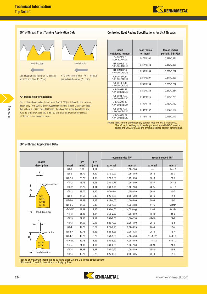
www.kennametal.comE94
Top Notch™
Technical Information
NTC crest turning insert for 12 threadsper inch and finer (P ≤2mm)
60° V-Thread Crest Turning Application Data
“J” thread note for catalogue
NTC crest turning insert for 11 threadsper inch and coarser (P ≥3mm)
feed direction feed direction
NOTE: NTC inserts automatically control root to crest dimensions.Therefore, in setting up threading operations with NTC inserts,check the O.D. or I.D. at the thread crest for correct dimensions.
The controlled root radius thread form (SAE8879C) is defined for the external thread only. To machine the corresponding internal thread, choose any insert that will cut a unified class 2B thread, then bore the minor diameter to size. Refer to SAE8879C and MIL-S-8879C and SAEAS8879D for the correct “J” thread minor diameter values.
Controlled Root Radius Specifications for UNJ Threads
60° V-Thread Application Data
*Based on maximum insert radius size and class 2A and 2B thread specifications.**For metric D and E dimensions, multiply by 25,4.
insertdescription insert
D**(mm)
E**(mm)
recommended TP* recommended TPI*
external internal external internalNT-1 1,90 1,11 — 1,00–2,00 — 24–12
NT-2 28,70 1,90 0,70–3,00 1,25–3,50 36–8 20–7
NT-2-K 28,70 1,90 0,70–3,00 1,25–3,50 36–8 20–7
NTF-2 15,75 1,01 0,60–1,75 1,00–2,00 44–14 24–12
NTK-2 15,75 1,01 0,60–1,75 1,00–2,00 44–14 24–12
NTP-2 28,70 1,90 0,70–3,0 1,25–3,50 36–8 20–7
NT-3 37,59 2,46 1,25–4,00 2,00–5,00 20–6 12–5
NT-3-K 37,59 2,46 1,25–4,00 2,00–5,00 20–6 12–5
NT-3-C 37,59 2,46 2,50–4,00 4,00 (only) 11–6 6 (only)
NT-3-CK 37,59 2,46 2,50–4,00 4,00 (only) 11–6 6 (only)
NTF-3 21,08 1,37 0,60–2,50 1,00–2,50 44–10 24–9
NTK-3 21,08 1,37 0,60–2,50 1,00–2,50 44–10 24–9
NTP-3 37,59 2,46 1,25–4,00 2,00–5,00 20–6 12–5
NT-4 49,78 3,22 1,25–6,25 2,00–6,25 20–4 12–4
NT-4-K 49,78 3,22 1,25–6,25 2,00–6,25 20–4 12–4
NT-4-C 49,78 3,22 2,50–5,50 4,00–5,50 11–4 1/2 6–4 1/2
NT-4-CK 49,78 3,22 2,50–5,50 4,00–5,50 11–4 1/2 6–4 1/2
NTF-4 21,08 1,37 0,60–2,50 1,00–2,50 44–10 24–9
NTK-4 21,08 1,37 0,60–2,50 1,00–2,50 44–10 24–9
NTP-4 49,78 3,22 1,25–6,25 2,00–6,25 20–4 12–4
E
D
radius
NT-NTP-NT-KNT-C
feed direction
E
D
radius
NTF-NTK
feed direction
insertcatalogue number
nose radiuson insert
thread radius per MIL-S-8879A
NJ-3020R/L8NJP-3020R/L8 0,477/0,502 0,477/0,574
NJ-3014R/L12NJP-3014R/L12 0,317/0,342 0,317/0,381
NJ-3010R/L16NJP-3010R/L16 0,238/0,264 0,238/0,287
NJF-3012R/L14NJK-3012R/L14 0,271/0,297 0,271/0,327
NJF-3010R/L16NJK-3010R/L16 0,238/0,264 0,238/0,287
NJF-3009R/L18NJK-3009R/L18 0,210/0,236 0,210/0,254
NJF-3008R/L20NJK-3008R/L20 0,190/0,215 0,190/0,228
NJF-3007R/L24NJK-3007R/L24 0,160/0,185 0,160/0,190
NJF-3006R/L28NJK-3006R/L28 0,137/0,162 0,137/0,162
NJF-3005R/L32NJK-3005R/L32 0,119/0,142 0,119/0,142Th
read
ing
KM_Master12_Turning_E094_E095_Metric.qxp:Layout 1 3/6/12 2:18 PM Page E94

www.kennametal.com E95
Technical InformationTop Notch™
� API Thread Forms • Insert Applications Chart for API Rotary Shouldered Connections
� API Thread Forms • Product Thread Dimensions • Rotary Shouldered Connections (Inch)
V-.040 and V-.050 Product Thread Form Casing and Tubing Round Thread (Height Dimensions)
NOTE: All dimensions in inches.
*Minimum box size that can be threaded with a standard Top Notch insert due to minimum bore equipment.
threadform cresting
Kennametal insert
non-crestingtool joint
applicationminimumbox size*
V-.038R2" TPF4 TPI
V-.038R3" TPF4 TPI
V-.0502" TPF4 TPI
V-.0503" TPF4 TPI
V-.0403" TPF5 TPI
NDC-4038R/L24-E/IR4API382
NDC-4038R/L34-E/IR4API383
NDC-4050R/L24-E/IRAPI502
NDC-4050R/L34-E/IR4API503
NDC-3040R/L3NDC-4040R/L34-E/IR5API403
ND-3038R/L
ND-3038R/L
ND-4050R/L
ND-4050R/L
ND-3040R/LND-4040R/L
API #312-7/8 IF
API #56
5-1/2 API full hole
5-1/2 API regular
3-1/2 API regular
2-3/8 API internal flush2-7/8 API internal flush3-1/2 API internal flush
4 API internal flush4-1/2 API internal flush5-1/2 API internal flush6-5/8 API internal flush
4 API full holeAPI #23, API #26, API #31, API #35, API #38, API #40, API #44, API #46, API #50
API #56API #61API #70API #77
5-1/2 API full hole6-5/8 API regular6-5/8 API full hole
5-1/2 API regular7-5/8 API regular8-5/8 API regular
2-3/8 API regular2-7/8 API regular3-1/2 API regular4-1/2 API regular
axis of thread
taper shown exaggeratedbox
pin
threadform
taper inchper ft
threadheight,
not truncated
H
thread height,
truncated hn=hs
root truncation
Sm=Srsfm=frs
crest truncation
fcn=fcs
crest fcn=fcs
crest fm=frs
radius at thread corners
rpitch
pV-.038RV-.038RV-.040V-.050V-.050
23332
.216005
.215379
.172303
.215379
.216005
.121844
.121381
.117842
.147303
.147804
.038000
.038000
.020000
.025000
.025000
.056161
.055998
.034461
.043076
.043201
.065
.065
.040
.050
.050
—————
.038
.038
.020
.025
.025
.015
.015
.015
.015
.015
.250
.250
.250
width of flat
rootradiusrm=rrs
Sm
hnH
fcn
p
fcs
hs
Srs90°
fcn
r mfcs
60°
30°30°rrrs
thread element
10 TPI p=.1000
8 TPIp=.1250
H =.866pHs = hn =.626p-.007Srs = Sm =.120p+.002Scs = Scn =.120p+.005
.08660
.05560
.01400
.01700
.10825
.07125
.01700
.02000
Thre
adin
g
KM_Master12_Turning_E094_E095_Metric.qxp:Layout 1 3/6/12 2:18 PM Page E95

www.kennametal.comE96
General Machining GuidelinesTechnical Information
� American Buttress (7° Pressure Flank Leading) NTB-A Inserts • Push Type
NOTE: For balanced chip load, 15° infeed angle is suggested.
*NTB-4A insert only.**Can cut 16 or 20 threads per inch provided minor diameter
is 1.375" or larger.
NOTE: Special Buttress forms are available upon request.
Reference Dimensions
Internal Threading Limitations
Threads per Inch vs. Maximum Root Radius Chart (Inch)
internal threading limitationsNTB-2A Buttress threading inserts
TPI nominal thread size
minimum minordiameter
(inch)
810121620
1-3/41-5/81-1/21-1/41-1/16
1.6001.5051.4001.1751.002
internal threading limitations NTB-3 and NTB-4A Buttress threading inserts
TPInominal
thread size
minimum minordiameter
(inch)4*56810
12**
2-1/22-1/4
21-3/41-5/81-1/2
2.2002.0101.8001.6001.5051.400
insertD
(inch)A
(inch)nose radius
(inch)pitch based on
maximum radiusNTB-2A .133 .024 .002–.004 16–20 TPINTB-3A .171 .031 .005–.008 8–16 TPINTB-4A .218 .049 .008–.012 4–6 TPI
Infeed Angle vs. Chip Load: 7° Pressure Flank Leading.010" infeed
.0012" chip load
.007" chip load
0° infeed angle
.010" infeed
.0039" chip load
.0052" chip load
15° infeed angle
feed direction feed direction
A
nose radius
maximum depth with A-style insert
D
NTB-A insert
7° pressure flank of the thread being the leading flank
feed
anti-clockwise rotation
chuck
NTB-2RA
NTB-3RA
NTB-4RA
External Buttress7° pressure flank leading
chuck
anti-clockwise rotation
NTB-2LA
NTB-3LA
NTB-4LA
feed
7° pressure flank of the thread beingthe leading flank
7°
Internal Buttress7° pressure flank leading
Insert vs. Toolholder Orientation
external internal
seating surfacein toolholder
seating surface in bar
insertnotch
insertnotch
NTB-2RA
NTB-3RA
NTB-4RA
NTB-2LA
NTB-3LA
NTB-4LA
7°
TPI 20 16 12 10 8 6 5 4 3 2-1/2 2 1-1/2 1-1/4 1maximum root radius .0036 .0045 .0059 .0071 .0089 0.119 .0143 .0179 .0238 .0286 0.375 .0476 .0572 .0714
Thre
adin
g
KM_Master12_Turning_E096_E097_Metric.qxp:Layout 1 3/27/12 9:42 AM Page E96

www.kennametal.com E97
Technical InformationGeneral Machining Guidelines
� American Buttress (45° Clearance Flank Leading): NTB-B Inserts • PULL-type
*NTB-4B insert only.
Internal Threading Limitations
internal threading limitationsNTB-2B Buttress threading inserts
TPInominal
thread size
minimum minordiameter
(inch)810121620
1-3/41-5/81-1/21-1/41-1/16
1.6001.5051.4001.1751.002
internal threading limitations NTB-3 and NTB-4B Buttress threading inserts
TPInominal
thread size4*56810121620
2-7/82-3/42-3/82-1/81-7/81-5/81-1/21-7/16
minimum minordiameter
(inch)2.5752.5102.1751.9751.7551.5251.4071.378
45° clearanceflank of thethread being the leading flank
45° clearance flank of the thread being the leading flank
45°
anti-clockwise rotation anti-clockwise rotation
feed
feed
NTB-2LBNTB-3LBNTB-4LB
NTB-2RBNTB-3RBNTB-4RB
Internal Buttress 45° clearance flank leading
External Buttress 45° clearance flank leading
chuck chuck
insertnotch
insertnotch
sealingsurfacein bar
sealingsurface intoolholder
NTB-2LBNTB-3LBNTB-4LB
NTB-2RBNTB-3RBNTB-4RB
45° clearance flank leading
Insert vs. Toolholder Orientation
external internal
NOTE: For balanced chip load, a reverse 15° infeed angle is suggested.
insertD
(inch)A
(inch)nose radius
(inch)pitch based on
maximum radiusNTB-2B .133 .024 .002–.004 16–20 TPI
NTB-3B .171 .031 .005–.008 8–16 TPI
NTB-4B .218 .049 .008–.012 4–6 TPI
A
.010" infeed.010" infeed
.0052" chip load .0012"
chip load
.007"chip load.0039"
chip load
Reference Dimensions Infeed Angle vs. Chip Load: 45° Clearance Flank Leading
D
maximum depth with B-style insert
nose radius
15° infeed angle NTB-B insert
feed direction
0° infeed angle
feed direction
Thre
adin
g
KM_Master12_Turning_E096_E097_Metric.qxp:Layout 1 3/27/12 9:42 AM Page E97
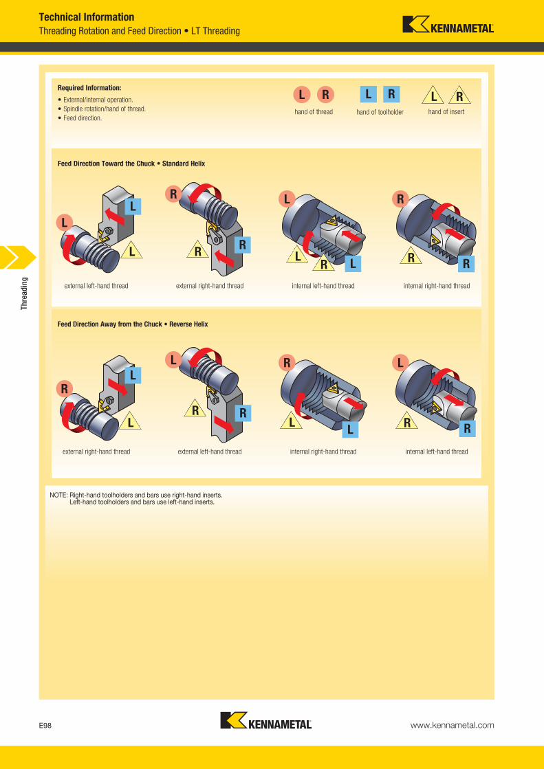
www.kennametal.comE98
Threading Rotation and Feed Direction • LT ThreadingTechnical Information
L
R
L
R
L
R
L
R
L R
L R
L R
LR
external left-hand thread external right-hand thread internal left-hand thread internal right-hand thread
external right-hand thread external left-hand thread internal right-hand thread internal left-hand thread
hand of thread hand of toolholder hand of insert
RLRL L R
R
R
R R
R
L
L
L
L
NOTE: Right-hand toolholders and bars use right-hand inserts.Left-hand toolholders and bars use left-hand inserts.
Required Information:
• External/internal operation.• Spindle rotation/hand of thread.• Feed direction.
Feed Direction Toward the Chuck • Standard Helix
Feed Direction Away from the Chuck • Reverse Helix
Thre
adin
g
KM_Master12_Turning_E098_E099_Metric.qxp:Layout 1 3/6/12 2:18 PM Page E98
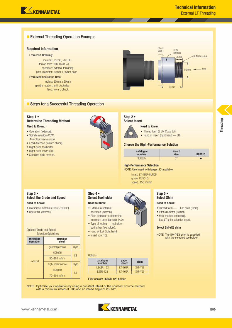
www.kennametal.com E99
Technical InformationExternal LT Threading
� Steps for a Successful Threading Operation
� External Threading Operation Example
chuckjaws CCW
rotation
feed
Required Information
From Part Drawing:
material: 316SS, 200 HBthread form: 8UN Class 2A
operation: external threadingpitch diameter: 50mm x 25mm deep
From Machine Setup Data:
tooling: 20mm x 20mmspindle rotation: anti-clockwise
feed: toward chuck
Step 1 • Determine Threading Method
Step 2 • Select Insert
25mm
70mm
50mm
8UN Class 2A
Need to Know:
• Operation (external).• Spindle rotation (CCW).
Anti-clockwise rotation.• Feed direction (toward chuck).• Right-hand toolholder.• Right-hand insert (ER).• Standard helix method.
Step 4 •Select ToolholderNeed to Know:
• External or internaloperation (external).
• Pitch diameter to determine minimum bore diameter (N/A).
• Type of tooling — toolholder, boring bar (toolholder).
• Hand of tool (right hand).• Insert size (16).
catalogue number
insert size KC5010
3ER8UN 3" �
High-Performance SelectionNOTE: Use insert with largest IC available.
insert: LT-16ER-8UNCBgrade: KC5010speed: 150 m/min
Need to Know:
• Thread form (8 UN Class 2A).• Hand of insert (right hand — ER).
Choose the High-Performance Solution
Step 3 • Select the Grade and SpeedNeed to Know:
• Workpiece material (316SS-200HB).• Operation (external).
Step 5 •Select ShimNeed to Know:
• Thread form — TPI or pitch (1mm).• Pitch diameter (50mm).• Helix method (standard).
See LT shim selection chart.
Select SM-YE3 shim
NOTE: The SM-YE3 shim is suppliedwith the selected toolholder.
First choice: LSASR-123 holder
Options:
Options: Grade and SpeedSelection Guidelines
threadingoperation
stainless steel
external
general purpose style
KC5025CB
50–360 m/min
high-performance style
KC5010CB
70–390 m/min
catalogue number
gageinsert shim
LSASR-123 LT-16ER SM–YE3LSSR-123 LT-16ER SM–YE3
NOTE: Optimise your operation by using a constant infeed or the constant volume method with a minimum infeed of .005 and an infeed angle of 29-1/2°.
Thre
adin
g
KM_Master12_Turning_E098_E099_Metric.qxp:Layout 1 3/6/12 2:18 PM Page E99

www.kennametal.comE100
External LT ThreadingTechnical Information
Required Information
From Part Drawing:
material: 4140 steelthread form: 16 TPI UN
operation: internal threadingpitch diameter: 40mm x 50mm deep
From Machine Setup Data:
tooling: 20mm boring barspindle rotation: clockwise
feed: away from chuck
Step 1 • Determine Threading Method
Step 2 • Select Insert
Need to Know:
• Operation (internal).• Spindle rotation (CW).
Clockwise rotation.• Feed direction (away from chuck).• Left-hand toolholder.• Left-hand insert (NL).• Reverse helix method.
Step 4 •Select ToolholderNeed to Know:
• External or internaloperation (internal).
• Pitch diameter to determineminimum bore diameter for internal operations (40mm).
• Type of tooling — toolholder, boring bar (boring bar).
• Hand of tool (left hand).• Insert size (16).
High-Performance SelectionNOTE: Use insert with largest possible IC to go into the bore.
insert: LT-16NL-16UNgrade: KC5025speed: 130 m/min
Need to Know:
• Thread form (16UN Class 2A).• Hand of insert (left hand — NL).
Choose the High-Performance Solution
Step 3 • Select the Grade and SpeedNeed to Know:
• Workpiece material (4010 steel).• Operation (internal).
Step 5 •Select ShimNeed to Know:
• Thread form — TPI or pitch (16 TPI).• Pitch diameter (40mm).• Helix method (reverse).
See LT shim selection chart.
Select SM-YE3-2N shim
NOTE: Shim supplied with selectedboring bar is not correct; ordercorrect shim.
chuckjaws
feed
70mm
CW rotation
40mm
16 TPI UN50mm
threading operation steel
internal
general purposeand high performance
KC5025
40–200 m/min
Options: Grade and SpeedSelection Guidelines
catalogue number
insertsize
minimum bore
diameter shimS1212-LSEL3 3" .90 SM-YE3
S0812-LSEL2 2" .65 —
First choice: S1212-LSEL3 bar
Options:
catalogue number
insert size KC5025
LT-11NL-16UN 1/4" �LT-16NL-16UN 3/8" �
� Steps for a Successful Threading Operation
Optimise your operation by using aconstant infeed or the constant volumemethod with a minimum infeed of .005and an infeed angle of 29-1/2º.
Thre
adin
g
KM_Master12_Turning_E100_E101_Metric.qxp:Layout 1 3/6/12 2:18 PM Page E100

www.kennametal.com E101
Technical InformationLT Threading
� LT Threading Shim Selection Guidelines
NOTE: For multistart threads, use the lead value instead of the pitch.
LT Selection Chart
feed
dire
ctio
n to
war
d th
e ch
uck
(sta
ndar
dhe
lix)
feed
dire
ctio
n aw
ay fr
om th
e ch
uck
(reve
rse
helix
)
LH thread/RH tooling RH thread/LH tooling
LH thread/LH toolingRH thread/RH tooling
The following questions must be answered before a successful threading operation can begin:
A — Select your method of thread cutting: • Machining toward the chuck (standard helix). • Machining away from the chuck (reverse helix).
B — Select lead angle and choose shim.
C — Select insert and toolholder size.
D — Select insert grade.
E — Select speed.
F — Select number of thread passes.
G — Select infeed method.
NOTE: When considering method of thread cutting, the part’s shapeand stability and the flow of chips are determining factors inyour decision.
pitch (mm)
pitch (mm)
10 –
9 –
8 –
7 –
6 –
5 –
4 –
3 –
2 –
1 –
0 –
1 –
2 –
3 –
4 –
5 –
6 –
7 –
8 –
9 –
10 –
Thre
adin
g
KM_Master12_Turning_E100_E101_Metric.qxp:Layout 1 3/6/12 2:18 PM Page E101

www.kennametal.comE102
LT ThreadingTechnical Information
� Diagram of Thread Lead Angles
TPI
TPI
pitch (mm)
SMYE
*3P
or S
MYI
*3P
SMYE
*1P o
r SMYI*
1P
SMYE *or S
MYI*
Standard
shim su
pplied with hold
er
SMYE* 1N or SMYI *1N
SMYE*1.5N or SMYI*1.5N
pitchdiameter
mm (inch)
SMYE*2N or SMYI*2N
SMYE*3N or SMYI*3N
SMYE*1.5N or SMYI*1.5N
SMYE
*2P
or S
MYI
*2P
pitch (mm)
To calculate the lead angle of a given thread, use this formula:
ß = thread lead angle
De = effective pitch diameter of thread wear
P = 1/TPI
TPI = threads per inch
S = number of starts
single-start, lead = pitch
multistart, lead = pitch (x) number of starts
ß = Arctan P•Sπ De
NOTE: Arctan equals Tan-1 (see chart below for approximate lead angles).
*denotes shim size: 3 = insert size 16 (3/8" D)4 = insert size 22 (1/2" D)
Standard Helix Method:
Used when RH thread is cut with RH tool or LH thread with LH tool.
Reverse Helix Method:
Used when RH thread is cut with LH tool or whenLH thread is cut with RH tool. Dimension “H” isconstant at every shim and insert combination.All toolholders are supplied with 1.5º lead angle.
All toolholders are designed with an inclination angle = 1.5°. When turning standard threads with a lead angle of 1–2°, this guarantees adequate clearance at the flanks of the insert’s thread tooth. The thread lead angle and the required inclination angle of the insert are given by ß.
Cutting edge height is constant at every shim and insert combination. All toolholders are supplied with 1-1/2° lead angle.
� LT Selection Chart
Thre
adin
g
KM_Master12_Turning_E102_E103_Metric.qxp:Layout 1 3/6/12 2:18 PM Page E102

www.kennametal.com E103
Technical InformationLT Threading
� LT Threading Shim Selection Table • Metric
toolholder shim ordering code (mm)
insert size external internal standardLT-16 (3/8") RH LH SM–YE3–3P SM–YE3–2P SM–YE3–1P SM–YE3 SM–YE3–1N SM–YE3–1.5N SM–YE3–2N SM–YE3–3NLT-16 (3/8") LH RH SM–YI3–3P SM–YI3–2P SM–YI3–1P SM–YI3 SM–YI3–1N SM–YI3–1.5N SM–YI3–2N SM–YI3–3NLT-22 (1/2") RH LH SM–YE4–3P SM–YE4–2P SM–YE4–1P SM–YE4 SM–YE4–1N SM–YE4–1.5N SM–YE4–2N SM–YE4–3NLT-22 (1/2") LH RH SM–YI4–3P SM–YI4–2P SM–YI4–1P SM–YI4 SM–YI4–1N SM–YI4–1.5N SM–YI4–2N SM–YI4–3N
72 — — — — 3,1–8 8–21,4 > 21,4 21,4–8 8–3,1— 0,35 — — — 3–8 8–21,3 > 21,3 21,3–8 3–864 — — — — 3,4–9 9–24,1 > 24,1 24,1–9 9–3,4— 0,40 — — — 3,5–9,1 9,1–24,3 > 24,3 24,3–9,1 9,1–3,556 0,45 — — — 3,9–10,3 10,3–27,6 > 27,6 27,6–10,3 10,3–3,9— 0,50 — — 2,8–4,3 4,3–11,4 11,4–30,4 > 30,4 30,4–11,4 11,4–4,348 — — — 3–4,6 4,6–12,1 12,1–32,2 > 32,2 32,2–12,1 12,1–4,644 — — — 3,3–5 5–13,2 13,2–35,1 > 35,1 35,1–13,2 13,2–5— 0,60 — 2,6–3,4 3,4–5,2 5,2–13,7 13,7–36,5 > 36,5 36,5–13,7 13,7–5,240 — — 2,8–3,6 3,6–5,5 5,5–14,5 14,5–38,6 > 38,6 38,6–14,5 14,5–5,5— 0,70 — 3–4 4–6,1 6,1–16 16–42,6 > 42,6 42,6–16 16–6,136 — — 3,1–4 4–6,1 6,1–16,1 16,1–42,9 > 42,9 42,9–16,1 16,1–6,1— 0,75 2,8–3,2 3,3–4,3 4,3–6,5 6,5–17,1 17,1–45,6 > 45,6 45,6–17,1 17,1–6,532 — 3–3,4 3,4–4,5 4,5–6,9 6,9–18,1 18,1–48,3 > 48,3 48,3–18,1 18,1–6,9— 0,80 3–3,5 3,5–4,6 4,6–6,9 6,9–18,2 18,2–48,6 > 48,6 48,6–18,2 18,2–6,928 — 3,4–3,9 3,9–5,2 5,2–7,9 7,9–20,7 20,7–55,1 > 55,1 55,1–20,7 20,7–7,927 — 3,6–4,1 4,1–5,4 5,4–8,2 8,2–21,4 21,4–57,2 > 57,2 57,2–21,4 21,4–8,2— 1,00 3,8–4,3 4,3–5,7 5,7–8,7 8,7–22,8 22,8–60,8 > 60,8 60,8–22,8 22,8–8,724 — 4–4,6 4,6–6 6–9,2 9,2–24,1 24,1–64,3 > 64,3 64,3–24,1 24,1–9,2— 1,25 4,7–5,4 5,4–7,1 7,1–10,8 10,9–28,5 28,5–76 > 76 76–28,5 28,5–10,820 — 4,8–5,5 5,5–7,2 7,2–11 11–28,9 29–77,2 > 77,2 77,2–28,9 29–1118 — 5,3–6,1 6,1–8 8–12,2 12,2–32,2 32,2–85,8 > 5,8 85,8–32,2 32,2- 12,2— 1,50 5,7–6,5 6,5–8,5 8,5–13 13–34,2 34.2–91.2 > 91,2 91,2–34,2 34,2–1316 — 6–6,9 6,9–9 9–13,8 13,8–36,2 36,2–96,5 > 96,5 96,5–36,2 36,2–13,8— 1,75 6,6–7,6 7,6–10 10–15,2 15,2–39,9 39,9–106,4 > 96,5 106,4–39,9 39,9–15,214 — 6,9–7,9 7,9–10,3 10,3–15,7 15,7–41,4 41,4–110,3 > 110,3 110,3–41,4 41,4–15,713 — 7,4–8,5 8,5–11,1 11,1–17 17–44,5 44,5–118,8 > 118,8 118,8–44,5 44,5–17— 2,00 7,6–8,7 8,7–11,4 11,4–17,4 17,4–45,6 45,6–121,6 > 121,6 121,6–45,6 45,6–17,412 — 8–9,2 9,2–12 12,1–18,4 18,4–48,2 48,3–128,7 > 128,7 128,7–48,2 48,3–18,4
11.5 — 8,4–9,6 9,6–12,6 12,6–19,2 19,2–50,3 50,3–134,3 > 134,3 134,3–50,3 50,3–19,211 — 8,8–10 10–13,1 13,1–20 20–52,6 52,6–140,4 > 140,4 140,4–52,6 52,6–20— 2,50 9,5–10,8 10,8–14,2 14,2–21,7 21,7–57 57–152 > 152 152–57 57–21,710 — 9,6–11 11–14,5 14,5–22 22–57,9 57,9–154,4 > 154,4 154,4–57,9 57,9–229 — 10,7–12,2 12,2–16,1 16,1–24,5 24,5–64,3 64,3–171,6 > 171,6 171,6–64,3 64,3–24,5— 3,00 11,4–13 13–17,1 17,1–26 26–68,4 68,4–182,4 > 182,4 182,4–68,4 68,4–268 — 12–13,8 13,8–18,1 18,1–27,6 27,6–72,4 72,4–193 > 193 193–72,4 72,4–27,6— 3,50 13,3–15,2 15,2–19,9 19,9–30,4 30,4–79,8 79,8–212,8 > 212,8 212,8–79,8 79,8–30,47 — 13,8–15,7 15,7–20,7 20,7–31,5 31,5–82,7 82,7–220,6 > 220,6 220,6–82,7 82,7–31,5— 4,00 15,2–17,3 17,3–22,8 22,8–34,7 34,7–91,2 91,2–243,2 > 243,2 243,2–91,2 91,2–34,76 — 16–18,3 18,3–24,1 24,1–36,7 36,7–96,5 96,5–257,4 > 257,4 257,4–96,5 96,5–36,7— 5,00 19–21,7 21,7–28,5 28,5–43,4 43,4–114 114–304 > 304 304–114 114–43,45 — 19,3–22 22–28,9 28,9–44,1 44,1–115,8 115,8–308,8 > 308,8 308,8–115,8 115,8–44,1
4.5 — 21,4–24,5 24,5–32,1 32,1–49 49–128,7 128,7–343,1 > 343,1 343,1–128,7 128,7–49— 6,00 22,7–26 26–34,2 34,2–52,1 52,1–136,8 136,8–364,8 > 364,8 364,8–136,8 136,8–52,14 — 24,1–27,5 27,5–36,2 36,2–55,1 55,1–144,8 144,8–386 > 386 386—144,8 144,8—55,1
inclination angle 4.5 3.5 2.5 1.5 0.5 0.0 -0.5 -1.5
feed directionstandard helix
(feed toward the chuck)reverse helix
(feed away from the chuck)
1. Select TPI or pitch from the left-hand columns.2. Follow row to specified pitch diameter and the correct feed direction.3. Follow the column to the top for the required shim based on the toolholder and insert size.
TPI pitch (mm) pitch diameter (mm)
Thre
adin
g
KM_Master12_Turning_E102_E103_Metric.qxp:Layout 1 3/6/12 2:18 PM Page E103