kms array system
TRANSCRIPT

©2011 KJT Enterprises Inc. V 1.0
Array Data Acquisition System(Electromagnetics & microseismics
KJT Enterprises Inc. 6420 Richmond Ave., Suite 610
Houston, TX, 77057 USA
Tel.: +1.713.532.8144 Fax: +1.713.532.7776
Email: [email protected] www.KMSTechnologies.com
KMS Technologies
The Array Data Acquisition System is used for a variety of geophysical applications such as electromagnetics (EM) (MT, AMT, LOTEM, CSEM, CSAMT, TFEM, IP, etc.) and seismic data acquisition (microseismic, seismic/EM monitoring). This 2D/3D system consists of multi-channel acquisition units (KMS-820) controlled by a central control unit and optional transmitter for multi-channel EM and seismic data acquisition. The system is fully expandable and is capable of several survey configurations.
System highlights: • Flexible and easy adaptable system configurations • Lightweight, portable, rugged, low power consumption • Wireless network, GPS synchronized, wide bandwidth and dynamic range • 24-bit digital resolution, DC to 40 kHz signal bandwidth • Low cost with large channel count • Efficient field operations without cables • High sampling rate to adapt to various geophysical methods • Combined MT/AMT measurements to give high resolution mapping and great depth • Combined CSEM and natural source EM acquisition in one receiver deployment • Microseismic data acquisition • Same system is capable of acquiring different methods by adding optional transmitters or geophones
The KMS-ADAS is set up in a variety of survey configurations, from single recording unit, to 3D acquisition arrays.
The multi-channel acquisition unit(KMS-820) can be configured as 6, 3, or 2 channels for MT/AMT, LOTEM, CSAMT, CSEM, TFEM, and IP applications or 6 channels for seismic/EM data. The standard configuration of 6 channel acquisition unit has two electric (E) field measurements and three magnetic (H) field measurements. The 2 channel acquisition unit is used for electric field measurements.
The windows based software included with the system provides real-time monitoring and data QA/QC. The data is saved on a flash memory card and can be streamed via USB or a wireless network for real-time quality check.
The minimum configuration is at least one multi-channel acquisition unit. Additional acquisition units can be added for remote reference or array applications.
System configuration
KMS-820 data acquisition unit
LEMI-701 non-polarized electrodes
LEMI-120 induction coil (0.0001 – 1,000 Hz) LEMI-118 induction coil (1 – 70,000 Hz)

©2011 KJT Enterprises Inc. V 1.0
2
• MT, AMT: Magnetotellurics and Audio MT are used for basin reconnaissance and structure studies including near surface applications.
• CSAMT: Controlled Source Audio MT uses a transmitter to get better Signal-to-Noise (S/N) ratios for detailed structure investigations of the upper 2 km.
• TFEM, IP: Time-Frequency Domain ElectroMagnetics and Induced Polarization combine time and frequency domain electromagnetics for hydrocarbon and mineral exploration.
• LOTEM: Long Offset Transient ElectroMagnetics is applied to detailed structural investigations of the upper 5 km for hydrocarbon and geothermal Exploration & Production.
• Oil and gas exploration • Hydrocarbon reservoir dynamics and CO₂ storage monitoring • Metals and mineral exploration • Geothermal exploration • Engineering and environmental studies • Earthquake prediction research • Deep crustal research
KMS-ADAS system can be used for large scope 3D EM survey with densely spaced electric sensors and sparsely installed magnetometers. The system’s wireless network feature makes very efficient field operations without cables when conducting massive 3D EM survey.
Magnetotellurics (MT) and Audio MT (AMT) target different depth of investigation in hydrocarbon and geothermal exploration. For hydrocarbon exploration, high resistivity lithologies such as salt, basalt, and overthrusting often mask sediments. They are difficult to image with seismic data due to high velocities and diffuse scattering. Lithologies associated with large resistivity contrasts have been easily detected by MT method.
MT utilizes natural variations in the Earth’s magnetic field as a source. Natural MT signals come from a variety of induced currents caused by thunderstorms and the ionosphere. The frequency range of MT data spans from 0.0001 Hz to 10 Hz, and for AMT from 10 Hz to 20 kHz.
EM methods
Applications
3D EM array layout
MT applications

©2011 KJT Enterprises Inc. V 1.0
3
Survey Receiver Transmitter Sensors Applications / Depth
MT KMS-820
N/A
Electrode: LEMI-701 Magnetometer: LEMI-120 LEMI-118
Onshore / Deep targets & basin study
CSAMT KMS-820
KMS-500 Electrode: LEMI-701 Magnetometer: LEMI-118
Onshore, transition zone /Shallow targets
TFEM
KMS-820
KMS-500
Electrode: LEMI-701 Magnetometer: LEMI-140 LEMI-120 LEMI-118
Onshore, transition zone /Shallow to mid-depth targets
LOTEM KMS-820
KMS-500 Electrode: LEMI-701 Magnetometer: LEMI-140
Onshore, transition zone /Shallow to mid-depth targets
TFEM, IP
KMS-820
KMS-500
Electrode: LEMI-701 Magnetometer: LEMI-140 LEMI-120 LEMI-118
Onshore, transition zone /Shallow to mid-depth targets
CSEM
KMS-820
KMS-500
Electrode: LEMI-701 Magnetometer: LEMI-120 LEMI-118
Onshore, transition zone /Shallow to mid-depth targets
For large site count 2D and 3D MT or AMT surveys, the array configuration is more cost effective. The central control unit of the KMS-ADAS is capable of controlling several thousand recording units wirelessly. Standard distances are 5 miles without and- principally- unlimited with wireless relays.
Commercial benefits:
• Low cost for 2D or 3D MT and AMT surveys • High speed sampling rate allow acquiring MT and AMT data with the same unit • Fast and easy operation and deployment of multiple recording units • Customized wireless system for high speed data transfer rate and distance scope • Designed for dense acquisition spacing for data redundancy and high resolution data recording
Array recording configuration for 3D MT/AMT data acquisition
Following table shows the various system configuration options for different surveys and applications. System components can be mixed and matched in a modular fashion.
2D or 3D MT survey configurations
System configuration table
©2011 KJT Enterprises Inc. V 1.0
4
www.KMSTechnologies.com
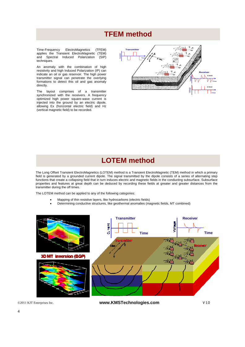
Time-Frequency ElectroMagnetics (TFEM) applies the Transient ElectroMagnetic (TEM) and Spectral Induced Polarization (SIP) techniques.
An anomaly with the combination of high resistivity and high Induced Polarization (IP) can indicate an oil or gas reservoir. The high power transmitter signal can penetrate the overlying formations to detect this oil and gas anomaly directly.
The layout comprises of a transmitter synchronized with the receivers. A frequency optimized high power square-wave current is injected into the ground by an electric dipole, allowing Ex (horizontal electric field) and Hz (vertical magnetic field) to be recorded.
Transmitter
Curre
nt
Time
Receiver
Volta
ge
Time
E-field
H-field
Volta
ge
Time
The Long Offset Transient ElectroMagnetics (LOTEM) method is a Transient ElectroMagnetic (TEM) method in which a primary field is generated by a grounded current dipole. The signal transmitted by the dipole consists of a series of alternating step functions that create a collapsing field that in turn induces electric and magnetic fields in the conducting subsurface. Subsurface properties and features at great depth can be deduced by recording these fields at greater and greater distances from the transmitter during the off times.
The LOTEM method can be applied to any of the following categories:
• Mapping of thin resistive layers, like hydrocarbons (electric fields) • Determining conductive structures, like geothermal anomalies (magnetic fields, MT combined)
TFEM method
LOTEM method
Receiver Transmitter
Time Time