knowledge sharing in distributed generic...
TRANSCRIPT
KNOWLEDGE SHARING IN DISTRIBUTED GENERIC INTRUSION DETECTION MODEL
By
MURUGA BHUPATHY CHENGALVARAYAN
A THESIS PRESENTED TO THE GRADUATE SCHOOL OF THE UNIVERSITY OF FLORIDA IN PARTIAL FULFILLMENT
OF THE REQUIREMENTS FOR THE DEGREE OF MASTER OF SCIENCE
UNIVERSITY OF FLORIDA
2002

Copyright 2002
by
Muruga Bhupathy Chengalvarayan

Dedicated to my parents.
ACKNOWLEDGMENTS
I would like to express my gratitude to Dr. Richard Newman for his constant
encouragement, support and invaluable advice throughout the course of this project. I
would also like to thank Dr. Randy Chow, Dr. Joseph Wilson and Dr. Jonathan Liu for
their guidance and help. I would like to express my gratitude to the other members of the
team, Akhil Karkera and Matthew Wilson, for their contributions, support and help.
iv
TABLE OF CONTENTS
page
ACKNOWLEDGMENTS.................................................................................................. iv
LIST OF FIGURES...........................................................................................................vii
ABSTRACT.....................................................................................................................viii
CHAPTER 1 INTRODUCTION............................................................................................................ 1
1.1 Basic Concepts .......................................................................................................... 1 1.1.1 Intrusion Detection System ............................................................................. 1 1.1.2 Need for Intrusion Detection........................................................................... 1 1.1.3 Classification of Intrusion Detection............................................................... 2
1.1.3.1 Host-based systems ............................................................................... 2 1.1.3.2 Network-based systems......................................................................... 3 1.1.3.3 Based on technique................................................................................ 3 1.1.3.4 Based on architecture ............................................................................ 4
1.2 Desirable Characteristics........................................................................................... 5 1.3 Major Issues in IDS................................................................................................... 6 1.4 Document Organization ............................................................................................ 7
2 LITERATURE REVIEW................................................................................................. 8
2.1 Hierarchical Models .................................................................................................. 8 2.1.1 An Architecture of Intrusion Detection Using Autonomous Agents .............. 8 2.1.2 GrIDS – Graph Based Intrusion Detection System......................................... 9 2.1.3 EMERALD.................................................................................................... 10
2.2 Disadvantages in Hierarchical Models.................................................................... 11 2.3 Distributed Architecture with Active Information Sharing..................................... 12
2.3.1 JiNao.............................................................................................................. 12 2.3.2 DIDS.............................................................................................................. 13 2.3.3 CSM............................................................................................................... 15 2.3.4 CARDS.......................................................................................................... 16 2.3.5 Other Architectures and Approaches............................................................. 18
2.4 Summary ................................................................................................................. 20
v
3 ARCHITECTURE ......................................................................................................... 21
3.1 Detectors.................................................................................................................. 21 3.2 Transceivers ............................................................................................................ 21 3.3 Coordinator.............................................................................................................. 22 3.4 Events ...................................................................................................................... 22 3.5 Rule-base................................................................................................................. 23 3.6 Communicator......................................................................................................... 23 3.7 Response Agents ..................................................................................................... 23 3.8 Interfacing the Different Components..................................................................... 24 3.9 Summary ................................................................................................................. 25
4 KNOWLEDGE SHARING............................................................................................ 26
4.1 Description .............................................................................................................. 27 4.2 Detailed Working and Implementation ................................................................... 29 4.3 Using Digest from Remote Stores........................................................................... 32 4.4 Database Schema..................................................................................................... 32 4.5 Querying for More Specific Information ................................................................ 33
4.5.1 Message Format for Requesting Information................................................ 33 4.5.2 Format of Query ............................................................................................ 34 4.5.3 Examples of Query ........................................................................................ 34
4.6 Applications of Knowledge Sharing ....................................................................... 35 4.6.1 Learning New Attacks................................................................................... 35 4.6.2 Automatically Update New Signatures and Rules ........................................ 35 4.6.3 Reacting to Attacks ....................................................................................... 36 4.6.4 Recovery from Failures ................................................................................. 36 4.6.5 Take Pro-active Measures ............................................................................. 37
4.7 Summary ................................................................................................................. 37 5 CONCLUSION AND FUTURE WORK....................................................................... 38
5.1 Conclusion............................................................................................................... 38 5.2 Future Work. ........................................................................................................... 38
KNOWLEDGE STORE TABLES.................................................................................... 40
LIST OF REFERENCES .................................................................................................. 44
BIOGRAPHICAL SKETCH............................................................................................. 47
vi
LIST OF FIGURES
Figure page
2-1 Physical layout of components in AAFID system ......................................................... ..9
2-2 CARDS architecture ...................................................................................................... 17
3-1 Schematic of DGIDEM architecture............................................................................... 24
4-1 Knowledge cells and knowledge network ...................................................................... 28
4-2 Communication sequence for digest request .................................................................. 30
A-1 Simplified database relationship diagram...................................................................... 43
vii
Abstract of Thesis Presented to the Graduate School
of the University of Florida in Partial Fulfillment of the Requirements for the Degree of Master of Science
KNOWLEDGE SHARING IN DISTRIBUTED GENERIC INTRUSION DETECTION MODEL
By
Muruga Bhupathy Chengalvarayan
December 2002
Chair: Dr. Richard Newman Department: Computer and Information Science and Engineering
Network Intrusion Detectors have tended to be huge monolithic systems that are
difficult to manage and scale. More work is being done currently on hierarchical and
distributed models that scale well to larger systems. However, more needs to be done in
the area of information sharing between these distributed components. The potential
advantages of information sharing between cooperating systems are many.
This thesis focuses on creating a mechanism for sharing data and information between
cooperating distributed intrusion detection systems. An existing schema for Snort, a
lightweight intrusion detector, was changed and adapted to facilitate the broader
knowledge sharing goals of this thesis. The underlying architecture for communication
and information exchange was designed and built. This thesis lays the groundwork that
would enable seamless sharing of information to learn about new attacks, share
signatures and rules, and provide information on network activity outside the boundaries
of a single network.
viii

CHAPTER 1 INTRODUCTION
1.1 Basic Concepts
The concept of intrusion detection was first established in the 1980s by Anderson [2]
and was later refined by Dennings [9]. Intrusion detection systems are designed to detect
and prevent unauthorized access to a computing resource or privileged data. In addition
to traditional intrusion prevention techniques, such as firewalls and password protection,
intrusion detection, has been widely regarded as the second line of defense for computer
security. The following sections describe intrusion detection systems in more detail.
1.1.1 Intrusion Detection System
An intrusion detection system is a system that monitors and detects intrusions or
unauthorized access that aim at subverting the availability, confidentiality and integrity of
services and data on a network. The system attempts to protect information infrastructure
against denial of service (DoS) attacks, unauthorized disclosure of information and the
modification or destruction of vital data. The system protects services and data from both
“insiders” (people who have legitimate access, but abuse their privileges) and from
“outsiders” (persons without legitimate access to data and services).
1.1.2 Need for Intrusion Detection
Intrusion detection systems are required to protect sensitive data from unauthorized
users. With the rapid expansion in technologies, it has been hard to keep up with issues
that relate to securing information, monitoring information flow, preventing information
leakage and abuse of services. New technologies and enhancements to existing
1
2
technologies bring with them new vulnerabilities or weakness that can be exploited to
compromise systems. Compromised systems may have their confidential information
stolen, sabotaged or destroyed. Worse still, intruders may be able to take over critical
services, leading to loss and damage. These problems are not confined to the commercial
sectors alone. Networks are connecting more and more government and military agencies
and disruption of these networks may be disastrous.
Intrusion detection systems help to detect intrusions, identify the perpetrator,
prevent intrusion if possible, provide forensic evidence for prosecution, and provide
information to close the exploit that caused the system to be compromised.
1.1.3 Classification of Intrusion Detection
Intrusion detection systems can be classified into many categories based on where
they are deployed, their underlying technology, or based on their architecture.
Traditionally, intrusion detection systems have been classified into host-based and
network-based systems. The following section describes each of these systems briefly.
1.1.3.1 Host-based systems
These systems reside on the host that is to be monitored. They monitor the flow of
information between communicating hosts. They actively scan the system for breaches in
the security policy. Host-based detectors may employ misuse or statistical anomaly
detection techniques for this purpose. They also frequently check the integrity of system
files and monitor user activities. An example of one such detector that monitors system
files and user activities is Tripwire [28]. Another example of host-based detector is
Haystack [23].
3
1.1.3.2 Network-based systems
These systems are deployed on networks or network segments and monitor all
packets traveling on the segment. Network-based detectors try to determine if the
network traffic flowing into the segment is potentially intrusive in nature. They analyze
the packets to detect malformed packets, port scans and other kinds of probing performed
prior to attacks. Network detectors look for certain patterns in the packet to detect attacks
much in the same way a virus scanner looks for patterns of code in files. Since network
detectors can be deployed on a stand-alone machine, they are operating system
independent. Some examples of network-based detectors are GrIDS [27], EMERALD
[22], and AAFID [3,26].
1.1.3.3 Based on technique
Based on the underlying technique adopted for detection, the systems are classified as
misuse detection and anomaly detection.
Misuse detectors. Misuse detectors look for patterns of known attacks and raise an
alert when a predefined pattern in found. They operate much in the same way as a virus
detector works—looking for pre-established patterns that denote intrusive activities.
Some examples of misuse detectors include State Transition Analysis Toolkit [16] and
Colored Petri Automata [20]. Misuse detectors are capable of detecting known attacks
reliably, however, they fail to recognize unknown or new attacks.
Anomaly detectors. Anomaly detectors model the user’s behavior on a system. When
the user’s behavior deviates sufficiently from the established behavior, it raises an alert.
The detector considers any deviation from pre-established behavior as the result of a
system compromise. Examples of anomaly detectors include NIDES [1] and Haystack
[23]. Anomaly detectors perform well when detecting new attacks, however, they are not
4
very efficient in recognizing known attacks. Also, it is possible to subvert the system by
progressively modifying the behavior such that the detector incorrectly begins to
recognize intrusive activities as normal acceptable activities.
Hybrid detectors. Recent detectors have begun to include both the features of misuse
detectors as well as anomaly detectors. These detectors combine the characteristic
advantages of both the above models. Examples include EMERALD [22] and JiNao [18].
1.1.3.4 Based on architecture
Based on architecture, the intrusion detection systems may be classified as
monolithic, hierarchical and distributed.
Monolithic detectors. Monolithic detectors represent the simplest form of
detectors. They contain all subunits that detect attacks, coordinate communication and
information from other detectors and the response units that react to these attacks in one
single program. The main feature of such detectors is that they do not share information
or interact with other similar systems outside their boundaries.
Hierarchical detectors. Hierarchical systems maintain a parent-child or master-
slave relation among a number of different independent and autonomous units that are all
working together to collect data, monitor events and detect intrusions. Information
generated by one unit is fed into higher-level units capable of summarizing and
correlating different information to form a better picture of network activities. The units
in these systems may be viewed as nodes in a tree, with the detectors being the leaves and
the intermediate nodes as data processing units.
Distributed detectors. Distributed systems remove single points of failure that exists
in hierarchical systems. Distributing the detection and data-analyzing units over the entire
network makes them more resistant to attacks that aim at bringing down the intrusion
5
detection system. Distributed systems allow for greater scalability, respond more
effectively to large scale distributed attacks and allow for automated sharing of
information between them. The communication between different units in this system is
on a peer-to-peer basis.
1.2 Desirable Characteristics
Crosbie and Spafford [7] and Balasubramaniyan et al. [3] have described some
characteristics that an intrusion detection system should possess. These characteristics are
reproduced below. An intrusion detection system should
• Be capable of running continuously with minimum or no human interaction.
• Be fault-tolerant. Other agents should be able to take over the functions of a failed agent. Upon recovery, the agent should be able to reload its previous state and continue working.
• Be able to resist subversion. Intrusion detection should be capable of monitoring itself to prevent any unauthorized changes to its code, configuration or signature files.
• Be easy to configure, deploy and maintain. The underlying policy should be clear and easily understood by those who deploy it.
• Detect intrusions or attempts to subvert the confidentiality, availability or the integrity of the data.
• Should be scalable in nature and be able to monitor large number of hosts.
• Should provide graceful degradation of service. If some components of the architecture should fail, the rest of the system should be affected as minimally as possible.
• Should allow for dynamic reconfiguration. The individual components should be able to support reconfiguration without having to restart the entire IDS.
The above sections described intrusion detection in general, the different types
and the desirable features in a good detection system. Current research in this field is
mainly focused on developing distributed systems that use combination of detection
methods and are scalable to large networks.

6
1.3 Major Issues in IDS
This section describes some of the shortcomings of in current commercial
detectors. Intrusion detection systems are constantly evolving to meet the growing
challenges in the security field. Work is being done to improve the limitations that exist
in some of the current implementations of intrusion detection systems. As networks and
attacks become increasingly sophisticated, monolithic detectors are not suitable to
monitor and respond to large-scale distributed attacks. Hierarchical detectors are better
resistant to modern attacks, but are increasingly difficult to scale as networks grow in
size. Hierarchical models usually have their data analysis concentrated in few higher-
level modules, resulting in single points of failures. Most implementations of current
intrusion detection systems do not coordinate or share information with other similar
systems. Most detectors have a very rigid implementation, in the sense that it is often
difficult to tailor detection mechanisms to particular needs. It is difficult to interface new
detectors to the existing system or to remove some detectors from the system.
Traditionally intrusion detection systems have focused on detecting attacks and do not
have very good response strategies. Though many current implementations are beginning
to include automated response to attacks, they are limited in their abilities. New
responses cannot be easily added nor can existing ones be easily changed.
The Distributed Generic Intrusion Detection Model (DGIDEM) addresses some
of these issues. The architecture provides a very flexible configuration of different
detectors and response agents. This thesis focuses on the establishment of a distributed
knowledge base and a framework for sharing information between different intrusion
detection systems.

7
1.4 Document Organization
The thesis has been organized in the following manner. Chapter 1 gives a brief
overview of the underlying concepts and the objective of this thesis. Chapter 2 describes
some of the related architectures and past work done in this field by other researchers.
Chapter 3 describes the DGIDEM architecture and its characteristics in detail. Chapter 4
describes the distributed knowledge sharing among different systems. Finally chapter 5
talks about conclusion and future work.
CHAPTER 2 LITERATURE REVIEW
There have been a number of architectures developed for distributed intrusion
detection. This chapter discusses some of the relevant architectures starting with
hierarchical models with little or no information sharing and proceeding to models that
actively share information between different distributed components.
2.1 Hierarchical Models
2.1.1 An Architecture of Intrusion Detection Using Autonomous Agents
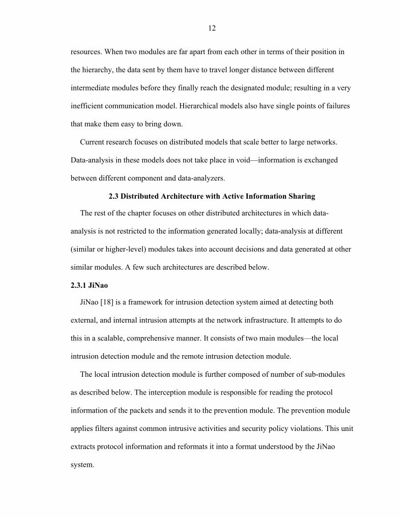
AAFID [3,26] is one of the earliest architecture to employ autonomous agents for
detection. The system is composed of three main components—agents, transceivers and
monitors. The agents are the primary data collectors, and are responsible for intrusion
detection. Agents can be distributed across different hosts in the network. Every agent on
a single host reports to a transceiver that oversees the operation of these agents.
Transceivers are per-host entities and control the activation, termination and
reconfiguration of the agents. Transceivers collect data from the agents, reformat it and
send it to the monitors.
Each monitor oversees the operation of several transceivers. Since each transceiver
essentially reports activity at individual hosts, and several transceivers report to a
monitor, the monitor has access to network-wide data. This allows them to perform
higher-level correlation and detect intrusions at several hosts. Monitors in turn, can be
organized into hierarchical fashion with several monitors reporting to higher-level
monitors. Also to provide redundancy and data-reliability, a single transceiver may report
8
9
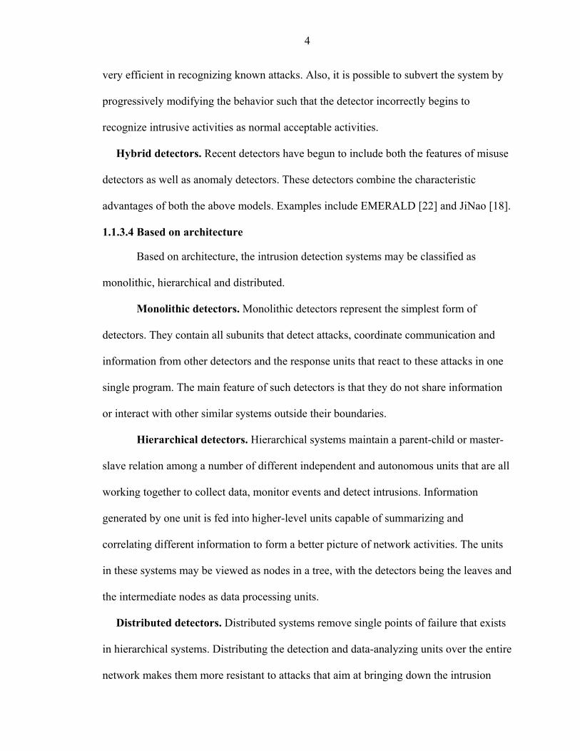
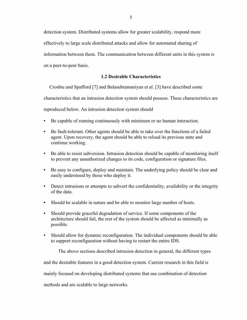
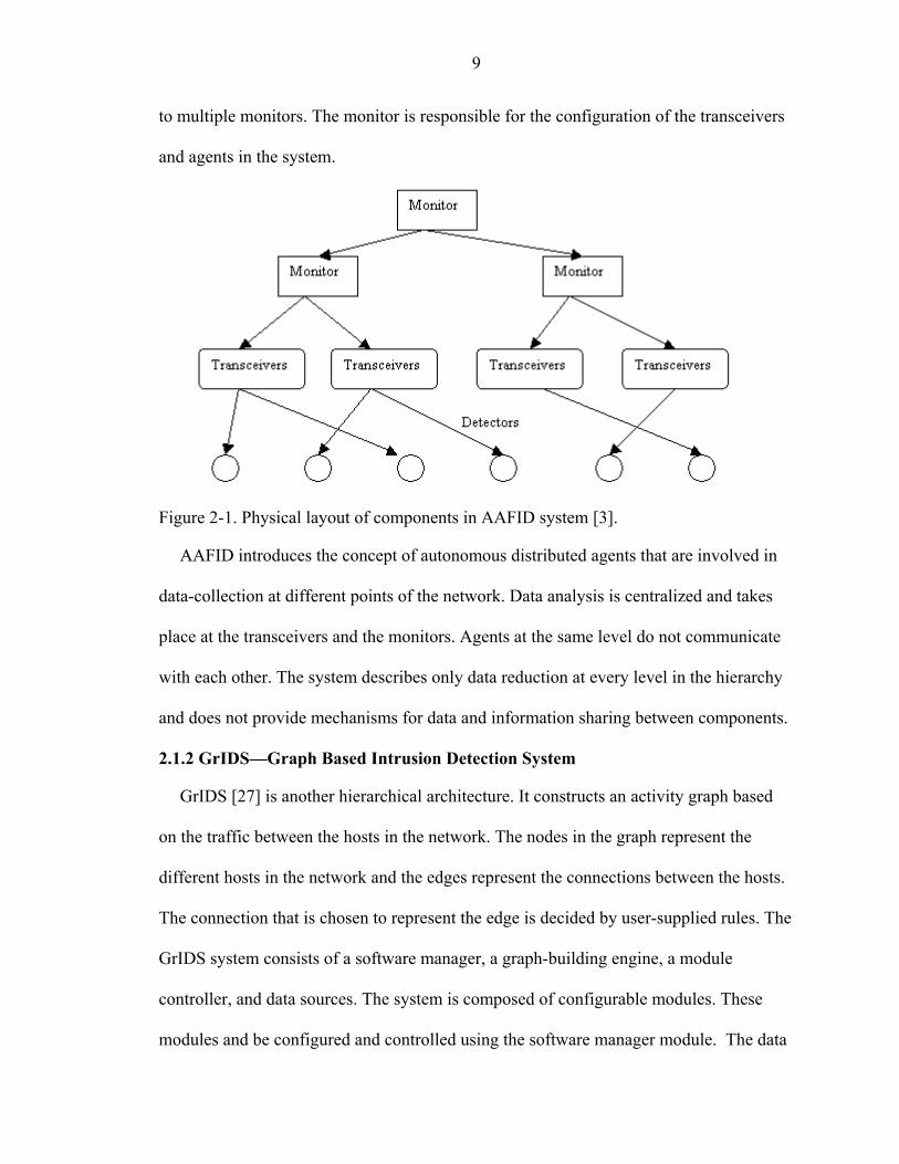
to multiple monitors. The monitor is responsible for the configuration of the transceivers
and agents in the system.
Figure 2-1. Physical layout of components in AAFID system [3].
AAFID introduces the concept of autonomous distributed agents that are involved in
data-collection at different points of the network. Data analysis is centralized and takes
place at the transceivers and the monitors. Agents at the same level do not communicate
with each other. The system describes only data reduction at every level in the hierarchy
and does not provide mechanisms for data and information sharing between components.
2.1.2 GrIDS—Graph Based Intrusion Detection System
GrIDS [27] is another hierarchical architecture. It constructs an activity graph based
on the traffic between the hosts in the network. The nodes in the graph represent the
different hosts in the network and the edges represent the connections between the hosts.
The connection that is chosen to represent the edge is decided by user-supplied rules. The
GrIDS system consists of a software manager, a graph-building engine, a module
controller, and data sources. The system is composed of configurable modules. These
modules and be configured and controlled using the software manager module. The data

10
sources are basically the detectors that monitor the hosts and the network, and report
events to the GrIDS system.
The graph-building modules builds the graphs based on the input from the data
sources and the rules specified by the user. The rules determine how the graphs are to be
constructed, what graph is to be merged with other graphs to form higher-level graphs,
what action to take when graphs are merged, and what parameters are used for the
construction of the graphs.
The system represents the network activity graphically and the authors claim that such
a visual representation of network activity will aid in the detection of network
compromise. Some of the large-scale intrusions identified by the authors include network
sweep, coordinated attacks and attacks by worms. In case of network sweeps, a single
host makes connection to a number of other hosts in the network in a relatively short
period. This can be easily identified from the activity graph. In case of coordinated
attacks, a large number of hosts try to connect to a particular host in parallel in order to
overwhelm its resources. In the case of a worm, a compromised system systematically
connects to other hosts in order to compromise them.
GrIDS is an hierarchical model in which lower-level data is processed as it moves up
in the hierarchy. It does not provide a framework for extracting and sharing specific
information with other components.
2.1.3 EMERALD
EMERALD [22] is an intrusion detection framework intended to be scalable in nature.
EMERALD adopts a recursive framework in which generic modules are deployed in a
hierarchical manner. The main module is the EMERALD monitor that is deployed
throughout the system. It uses a push/pull mechanism to communicate with other

11
modules deployed on the network. The system consists of the following modules –
resource object, analysis engines and resolver. The resource object maintains the various
parameters needed by the analysis engines and the resolver module. It also contains the
responses that should be invoked when certain conditions are met. The profiler engine
uses the data collected to detect deviation from established behavior. The system has a
signature engine that detects predefined intrusive activities. The universal resolver
correlates information from different modules to detect intrusions and to decide
appropriate responses.
EMERALD has well defined interfaces that would allow it to interoperate with other
intrusion detectors. The modules are organized into layers with communication taking
place at different levels - between the modules at peer level, and upwards to higher-level
modules. EMERALD organizes IDSs for individual hosts under the IDSs for
departments, which are under an IDS for the entire enterprise. This makes the
architecture basically a hierarchical one with higher-level modules becoming increasingly
complex. The authors claim that this hierarchical organization of monitors can detect
enterprise-wide large-scale attacks.
2.2 Disadvantages in Hierarchical Models
Hierarchical models such as the ones discussed above—AAFID, GrIDS and
EMERALD—do not scale well to large networks. Data communication is limited
between few pre-defined modules. At every level in the hierarchy, there is some amount
of data-refinement or data analysis being done. This makes the system difficult to modify
when new attacks are discovered. The bulk of the data analysis is restricted to few higher-
level modules. As the size of the network they monitor grows, these modules become
increasingly computational intensive and use higher percentage of CPU and bandwidth
12
resources. When two modules are far apart from each other in terms of their position in
the hierarchy, the data sent by them have to travel longer distance between different
intermediate modules before they finally reach the designated module; resulting in a very
inefficient communication model. Hierarchical models also have single points of failures
that make them easy to bring down.
Current research focuses on distributed models that scale better to large networks.
Data-analysis in these models does not take place in void—information is exchanged
between different component and data-analyzers.
2.3 Distributed Architecture with Active Information Sharing
The rest of the chapter focuses on other distributed architectures in which data-
analysis is not restricted to the information generated locally; data-analysis at different
(similar or higher-level) modules takes into account decisions and data generated at other
similar modules. A few such architectures are described below.
2.3.1 JiNao
JiNao [18] is a framework for intrusion detection system aimed at detecting both
external, and internal intrusion attempts at the network infrastructure. It attempts to do
this in a scalable, comprehensive manner. It consists of two main modules—the local
intrusion detection module and the remote intrusion detection module.
The local intrusion detection module is further composed of number of sub-modules
as described below. The interception module is responsible for reading the protocol
information of the packets and sends it to the prevention module. The prevention module
applies filters against common intrusive activities and security policy violations. This unit
extracts protocol information and reformats it into a format understood by the JiNao
system.

13
The detection module performs two functions. It determines if the packet information
received is in conformance with previously established behavior. It performs this by
using a statistical analysis module similar to the one used by the NIDES system [1]. The
system establishes a short-term behavior and a long-term behavior for each user based on
several parameters and when the short-term behavior varies sufficiently from its long-
term behavior, an alarm is raised by the system.
The other function performed by the module is protocol analysis. The protocol
analysis tries to establish if suspicious activities are taking place based on the specific
protocol under study and the traffic being generated. JiNao performs this analysis by
maintaining different state machines that represent the correct behavior of protocols. The
local decision module acts as an interface between the detection module, the management
information base, and the protocol engine. It also issues commands to update, modify or
activate rules in the prevention module. The decision module bases its decision on both
the information it receives from its local detection units and from the management
information base.
The management information base contains the historical communications between
the local JiNao subsystems and the remote modules. It allows the results of local
detection unit to be available at remote host.
This system introduces the concept of management information base that is used by
other data-analyzers while making decisions. However, it does not specify how the
information in it is used be other modules or what information is stored in it.
2.3.2 DIDS
DIDS [24] is a distributed intrusion detection system that is based on Haystack [23]
and NSM [15]. It consists of a three main components: a host detector, a LAN detector
14
and a DIDS director. Every host has a host detector that is responsible for local intrusion
detection and reporting. The host detector is in turn made up of five components. The
preprocessor unit is responsible for converting raw audit trial into canonical form that is
suitable for further processing. It performs data reduction and data filtering to reduce the
amount of traffic flowing through the different modules. The host detector contains a
signature analysis unit that scans for patterns to detect known security policy violations.
The notable event unit processes the canonical data for events such as logins and remote
logins, to check if the event is interesting enough to forward it to the DIDS director. The
Haystack module builds session profile of each user and uses it to look for anomalies
from the established profiles and communicates these anomalies to the DIDS director for
further analysis.
The LAN monitor is based on the NSM [15] model developed at UC Davis. This
module is responsible for monitoring the packets on the network segment to create a view
of significant events. It also builds profiles based on which host communicates with
which other hosts in the network and the protocol they use for communicating.
The DIDS director acts as a central point for data analysis. The director consists of
two main units—communication manager and the expert system. The communication
manager collects the data sent to it by the host detectors and the LAN monitors and feeds
it to the expert system. The expert system is a rule-based expert system that tries to make
inferences on the security state of the system and communicates it to the administrator.
The DIDS was able to track users as they moved across the network by sharing user
information with other components. However, the information shared is very limited and

15
data analysis is essentially limited to the directors. No mechanism is provided for sharing
information between the different data-analyzers.
2.3.3 CSM
In CSM [30] some degree of information sharing is achieved by having the agents on
the different hosts communicate to each other about the users who connect to these hosts.
However, the information shared is limited and does not provide any querying
mechanisms. In this system, each host runs a security manager that is primarily
responsible for detecting intrusions on the host machine. In addition to this, the system
also monitors for intrusive activities of the users on the machine who may be connected
to other hosts. In order to accomplish this, each security manager request information
about the user’s activities from other hosts. This enables a host to keep complete record
of the activities of the user and also aid in tracing the user’s connection across the
network.
The system consists of the different discrete modules that are explained briefly below.
The local intrusion detection module is responsible for monitoring the host on which it is
running for breaches in security policy. It maintains a “suspicion-level” for each user and
if this level exceeds a predefined threshold level, the system raises an alarm. The
distributed intrusion detection module is responsible for detecting intrusions or intrusive
behavior of a user on the local host connected to another host on the network. It
accomplishes this by communicating with the remote local intrusion detection module.
The user tracking module aids in tracking users as they move across the network. The
system has a response-handling unit that decides what action to take when intrusions are
discovered.
16
One major drawback of this system is that most of the analysis of the user’s behavior
is left to the host on which the user originally logs onto in the network. If the IDS on this
machine is compromised, the data analysis fails and the user will be able to continue
malicious activity across hosts in the network. Another limitation is the unavailability of
querying facilities. There is no dynamic sharing of new information or information
relating to new attacks.
2.3.4 CARDS
CARDS [29] is a scalable, signature-based distributed intrusion detection system that
focuses on detecting coordinated attacks over large-scale distributed systems. It employs
a decentralized data analysis technique. CARDS uses an audit-independent, structured
format to model attacks and lower-level audit information. CARDS allows multi-source
information to be easily correlated. The information is represent in form of system views.
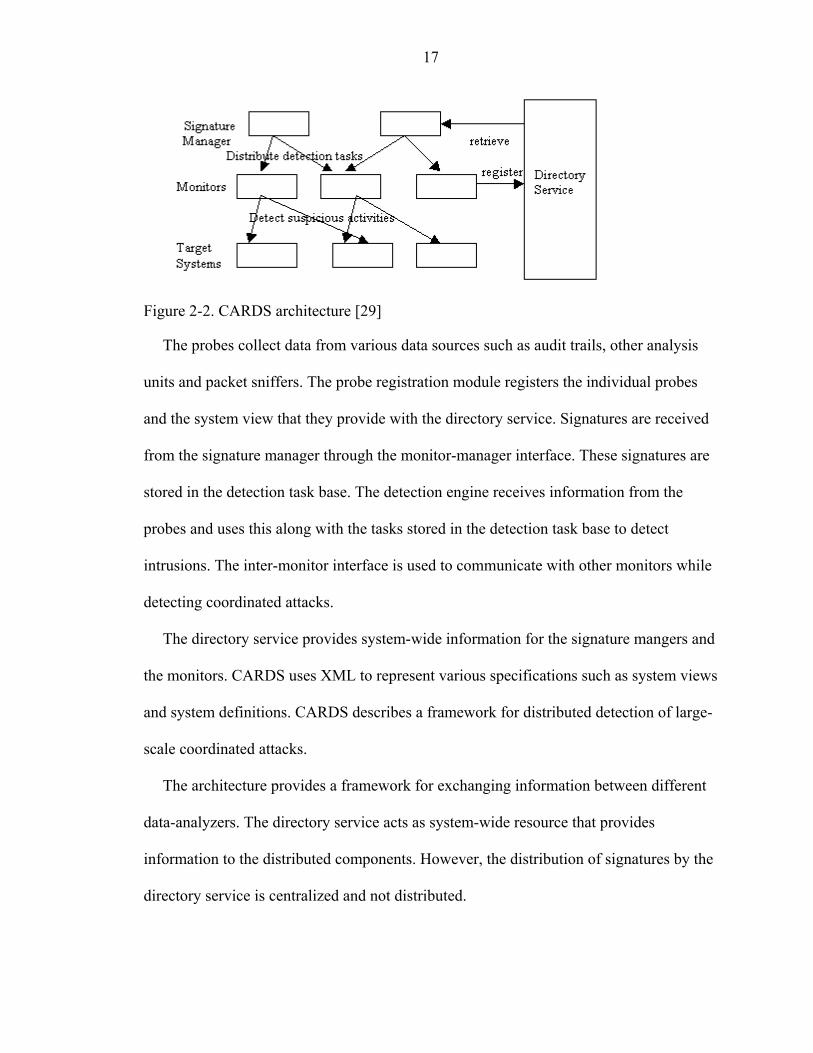
CARDS composes of three cooperating modules—the signature manger, monitor and
directory service. The signature manager is responsible for generating specific signatures
from more generic signatures, decompose signatures into detection tasks, and distribute
these signatures to other monitors. The system specifies the detection task within the
signature and assigns it to a monitor. To detect coordinated attacks, the signature is
decomposed into several detection tasks that are carried out by the different monitors.
Monitors are the components in the system that are responsible for detecting intrusive
activities. The signature manager assigns tasks to each monitor by distributing signatures
to it. In the case of coordinated attack detection, each distributed monitor cooperates with
other monitors during the detection process.
17
Figure 2-2. CARDS architecture [29]
The probes collect data from various data sources such as audit trails, other analysis
units and packet sniffers. The probe registration module registers the individual probes
and the system view that they provide with the directory service. Signatures are received
from the signature manager through the monitor-manager interface. These signatures are
stored in the detection task base. The detection engine receives information from the
probes and uses this along with the tasks stored in the detection task base to detect
intrusions. The inter-monitor interface is used to communicate with other monitors while
detecting coordinated attacks.
The directory service provides system-wide information for the signature mangers and
the monitors. CARDS uses XML to represent various specifications such as system views
and system definitions. CARDS describes a framework for distributed detection of large-
scale coordinated attacks.
The architecture provides a framework for exchanging information between different
data-analyzers. The directory service acts as system-wide resource that provides
information to the distributed components. However, the distribution of signatures by the
directory service is centralized and not distributed.
18
2.3.5 Other Architectures and Approaches
The following section briefly describes other information sharing mechanisms in
related architectures.
Crosbie and Spafford [6] discuss broadcasting information about suspicious intrusive
activities to distributed agents monitoring the network. However, such broadcasting
mechanism becomes highly inefficient in a large network involving many agents. Barrus
and Rowe [4] and Ingram [17] propose an architecture in which agents transmit all alerts
to other agents that they know. Again, such a mechanism does not scale well to large
networks. The major drawback in such a mechanism is the communication overhead
involved when hundreds of agents are present. Gopalakrishna and Spafford [14] present a
framework for distributed intrusion detection in which the agents are the only data
analysis components and the framework uses interest-based mechanism to transfer data
between agents. Agents in the network propagate their interest in some activity up the
hierarchy and other agents communicate events only if it matches the interest advertised
by the other agent.
Bass [5] introduces the idea of multi-sensor data fusion to enhance the performance
and reliability of heterogeneous intrusion detectors. In this model, he proposes a system
where intrusion detectors interoperate in a uniform and cooperative model, fusing data
from different sensors into information and knowledge, so that network operators can
make informed decisions about the health and real-time security of their networks. The
inputs to this system are sensor data such as data from numerous packet sniffers, system
log-files, and a priori data from established databases such as user profile databases,
threat databases and operator controls. The output of the system is information about the
identity, location and assessments of severity of attacks.
19
The Common Intrusion Detection Framework (CIDF) [8] is an effort aimed at
enabling different intrusion detection and response agents to interoperate and share
information with each other. The framework breaks down the basic components in an
intrusion detection system into the following categories—event generators, event
analyzers, event databases and response units. Event generators are the components that
are responsible for data collection, intrusion detection and reporting these events to
higher-level components. They are referred to as E-boxes. Event analyzers (A-boxes) are
the components involved in correlating events and information from different event
generators. Event databases (D-boxes) are the components involved in storing the data
generated by the system and the response units (R-boxes) are the components that are
activated to respond to an intrusion alert. The Intrusion Detection Inter-component
Adaptive Negotiation (IDIAN) protocol [10] improves the CIDF components ability to
interoperate with each other. The protocol helps cooperating CIDF components reach an
agreement on each other capabilities and needs. The CIDF also supports query facilities
that enable the CIDF components to request specific information from each other. For
example, the MADAM [21] intrusion detector uses CIDF to automatically get audit data,
build models, and distribute signatures for new attacks.
The IETF’s Intrusion Detection Working Group (IDWG) has brought out a data
format for exchanging information between different IDSs. The format uses XML to
encode information that is to be shared between the different IDSs. The data format
called as Intrusion Detection Message Exchange Format (IDMEF) has been specified in a
internet draft [11]. Another similar project is the Hummer Project [12]. The Hummer
project provides a framework for sharing information between different IDSs. This
20
project addresses the different kinds of relationships between IDS (such as peer, master,
slave, etc). The project, however, does not address what information is to be shared
between different IDSs.
2.4 Summary
This chapter discussed some of the major architecture for hierarchical and distributed
models with emphasis on information exchange. The Distributed Generic Intrusion
Detection Model (DGIDEM) presented in the following chapters presents a framework
for distributed detection with mechanisms for information exchange and querying
capabilities.
CHAPTER 3 ARCHITECTURE
The Distributed General Intrusion Detection Model (DGIDEM) in an extension of
the General Intrusion Detection Model (GIDEM). The GIDEM architecture is described
in detail in Gandre’s [13] thesis and the DGIDEM architecture is explained in detail in
Karkera’s [19] thesis. This chapter introduces the main components of the DGIDEM and
briefly describes how they are interfaced in the system.
3.1 Detectors
Detectors are independent agents that monitor system components for intrusive
activities. They work by either monitoring the network traffic (network-based) or by
monitoring the host’s system audit files (host-based). Detectors can be of any kind—
misuse-based, statistical-based or hybrid. Third party detectors can also be easily
interfaced with the system. The primary function of detectors is to gather information and
report them to the coordinators. Detectors communicate with the coordinator with
messages called as events. When third party detectors are used, then transceivers are used
to translate detector-specific reports into the format understood by the system.
3.2 Transceivers
Transceivers or Interfaces are components that are used to interface third-party
detectors with coordinators. Transceivers are needed when different detectors are used
with the system, each using a different reporting scheme. They help by translating the
detector specific information into a format that is understood by the system. Transceivers
also act as data reduction units and reduce the amount of data reaching the coordinator.
21
22
3.3 Coordinator
The coordinator is the controller of the IDS. The coordinator receives and routes
messages to the appropriate sub-unit within the system. Since each unit in the system is
an independent entity, the coordinator acts as a central unit that coordinates the activities
of these units. Coordinator receives reports from the detectors and transceivers in form of
messages called events. Coordinator then looks up the rule-base to decide what action to
take when it receives events from other units. Coordinators also send and receive events
from other remote coordinators. It makes use of the communication module to send
messages to other remote coordinators. The coordinator is responsible for registering the
detectors and response agents that it uses. It verifies that the events that it receives are
from the legitimate units that have registered with it. When this system is extended to
incorporate mobile agents, then the coordinator will be responsible for maintaining the
list of active agents operating under it.
3.4 Events
Events are messages sent to the coordinator from the detectors and transceivers.
Events encapsulate information such as the originating detector, origination host,
alert/report to be communicated to the coordinator, and other name value parameters that
describe the message in quantified terms. Detectors report suspicious activities or
attempted intrusions to the coordinator. This information is expressed in terms of
parameters such as offending IP address or number of unsuccessful logins. These
parameters are expressed as name-value pairs in the event message. All units in the
system communicate through events. The unit receiving the events is responsible for
interpreting the parameters in it.
23
3.5 Rule-base
Rule-base contains the list of directives called rules that indicate what action to
take when certain events occur and certain conditions are met. Rules match events and
conditions to actions. Rules contain three parts—the event on which the rule is to be
initiated, a condition part, and an action part. The first part of the rule specifies the event
that triggers the action part when the condition part evaluates to true. Conditions make
rules very flexible. They help to initiate different actions for the same event depending on
the conditions. The conditions use the name-value pair parameters reported by the events.
The action part of the rule specifies the response agent to invoke. The complete
description and format of rules is specified in Gandre’s thesis [13].
3.6 Communicator
The communicator is used for sending and receiving messages between different
IDSs. The communicator interfaces directly with the coordinator and reports any
messages it receives from remote coordinators or remote detectors. When detectors wish
to report to remote coordinators, they send the event message through the local
communicator module.
3.7 Response Agents
These are agents that are triggered in response to certain events. They perform
pre-emptive activities like reconfiguring firewall or blocking traffic from certain IP
address, to reporting activities such as logging events or sending message to the
administrator or raising alerts. Response agents are invoked by the rule-base when a rule
is successfully matched. The arguments with which the response agents should be
invoked are specified in the rule. Response agents can be grouped under a response
server that micromanages the operations of different response agents.

24
3.8 Interfacing the Different Components
The components (detectors, coordinators, response agents, rule-base) can be
distributed across the network. They can be used independently on different hosts and yet
interact seamlessly with one another. This model is not hierarchical: interaction between
units and different IDS take place on a peer-to-peer basis.
Figure 3-1 Schematic of DGIDEM architecture [19].

25
3.9 Summary
This chapter provided an overview on the DGIDEM architecture. Some of the
DGIDEM components use the work done in the architectures described in the previous
chapter. However, this architecture also introduces new components such as the rule-
base, response server and heartbeat module, along with new design paradigms for
distributed and scalable intrusion detection. The complete description, implementation
and deployment of the DGIDEM architecture are described in Karkera’s [19] thesis. The
following chapter describes the components and the framework for distributed knowledge
sharing in DGIDEM.
CHAPTER 4 KNOWLEDGE SHARING
Most current architectures of intrusion detection are stand-alone architectures.
They do not have well defined mechanisms for sharing data and information with one
another. Being able to share data with other intrusion detection systems (IDS) has many
advantages. Each IDS is then capable of learning from the activities that are monitored by
other intrusion detection systems.
In DGIDEM, every IDS cell has a dedicated logging host called the knowledge
store that logs all the activities of the detectors in its cell. Thus a knowledge store
essentially contains information about the activities that take place in its cell. When
different knowledge stores form a cooperating knowledge cell, information from one
store can be shared with another, thus enabling propagation of knowledge across cell
boundaries.
Sharing information in a cooperative environment leads to the following benefits.
• It allows IDS in the system to learn about how other IDS react to attacks. By sharing its rule-base an IDS can share information on what response it takes for different alerts. Along with information on what response agent is activated, the parameters used to invoke the agent are also shared. Other IDS may use this information to fine-tune their own response to similar alerts.
• It facilitates learning of new attack patterns. As every knowledge store receives
information from different hosts, it has access to a wider information-base that may be used to perform global network analysis or even learn of possible new attack scenarios.
• It facilitates automatic update of new signatures. When an IDS comes up with new
attack signatures, these signatures can be automatically distributed to all other IDSs in other cells.
26
27
• It facilitates recovery from failures. Knowledge stores contain basic information about the detectors, response agents, their execution state and information on other units that each IDS has deployed. When one of the IDSs goes down, another IDS in the cell can use that information to take over the functions of the failed IDS.
• Knowledge sharing facilitates propagation of rules and policies to all cell members.
New rules and configurations can be easily propagated to all members of the cell, thus reducing the work required for maintaining consistent copies of IDS running on different host.
• It provides a framework for querying other knowledge stores. An IDS may form an
hypothesis based on the information it has collected and query other IDSs for information required to validate the hypothesis. For example, an IDS may query other knowledge stores to find out if it has any information about an offending host.
• It allows the system to take pro-active measures. Based on the information that a
knowledge store receives from other knowledge stores, it may choose to turn off certain services, reconfigure a firewall, or block services to certain hosts, even before it actually faces problems.
The following sections describe the architectural design and implementation of
knowledge sharing in DGIDEM.
4.1 Description
Group of individual IDSs running on different hosts form an IDS cell. This cell
may be created based on the role of the hosts (e.g., file servers, web server, etc), based on
their location (physically nearby hosts) or based on certain organization (small network,
subnet, etc).
Each IDS cell in the architecture has a designated host that acts as the knowledge
store for that cell. All IDSs in that cell log information that they collect with this store.
Thus the store acts as repository of information collected from its cell. The knowledge
store can also function as data replication unit for fault tolerance. Different knowledge
stores, in turn, form a cooperating network of stores that share information. Group of
cooperating knowledge stores form a knowledge cell. Member stores share data and
28
information with each other. This facilitates propagation of data and information across
basic IDS cell boundaries, which in turn may mean, propagation of knowledge across
networks based on how the IDS cells are set up. IDS cell members may also overlap,
which would result in IDS logging information in multiple knowledge stores for data
redundancy and fault tolerance.
Different knowledge cells may have common members. The common members
act as bridges between the cells, allowing for information to flow between the two cells.
Using this technique of overlapping knowledge cells, a large distributed knowledge base
may be created. Such a large, distributed knowledge base with a sufficiently flexible
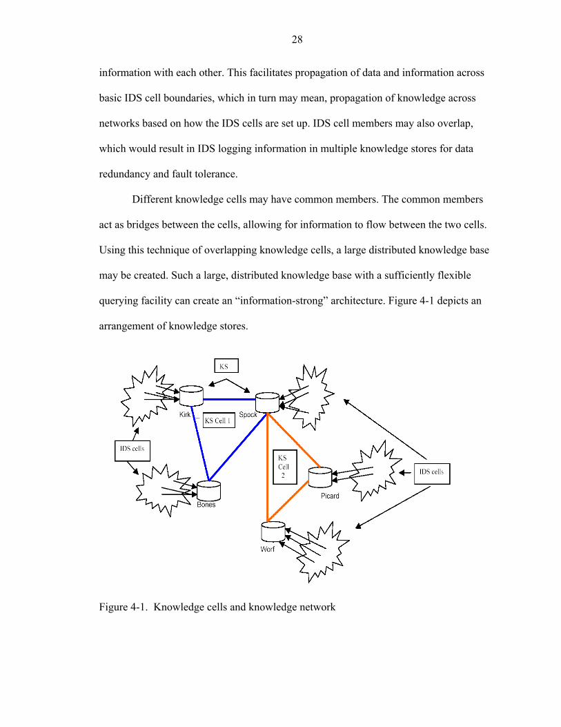
querying facility can create an “information-strong” architecture. Figure 4-1 depicts an
arrangement of knowledge stores.
Figure 4-1. Knowledge cells and knowledge network
29
In the above figure, the hosts Kirk, Spock, Bones, Picard and Worf are the knowledge
stores that form two knowledge cells—KS cell 1 and KS cell 2. Spock is the common
member in both the cells and acts as a bridge between the two cells. Spock receives
information from the members of Cell 1 and can share this information with the members
of Cell 2. Likewise, it receives information from members of Cell 2 and shares it with
Cell 1 members.
4.2 Detailed Working and Implementation
Each knowledge store logs the information sent to it by its IDS cell members. In
addition to this, it will periodically query other knowledge stores for a summary of attack
information that they have logged. Since, IDS cells and knowledge cells can overlap, care
was taken during implementation to ensure that redundant information was not received
from multiple stores. At this stage, information exchange could have been modeled on
either the "push" or the "pull" strategy. In the “push” model, information is pushed onto
the recipients whenever new information is available and in the “pull” model, the
recipient specifically requests for new information. Combination of both these strategies
was adopted during implementation. Whenever a store discovers or formulates a new
signature or rule, or when an important alert is to be sent, the store adopts a “push” model
and sends information to its members. The stores may also specifically request for new
information from other stores.
Knowledge stores have two agents running on them—the knowledge_request
(KR) agent and the request_service (RS) agent. The KR agent sends out request for
summary information. This summary information that is exchanged by the stores is called
as digest. The RS agent queries the local store and sends back the digest to the requesting
store.
30
The heartbeat agent sends out periodic reminders in the form of events to the
coordinator. When the coordinator receives this event, it looks it up in the rule-base,
where it is matched and the KR agent is activated.
The KR agent takes as parameters the remote store to query and determines the
timestamp of the latest digest received from that store. It then establishes a port to receive
the digest and sends a query event (with the port number and timestamp embedded as
parameters) to the remote coordinator though the local communicator.
When the remote communicator receives the event, it sends it to its coordinator, which
then matches it against its rule-base and triggers its RS agent. This agent then queries its
local store and sends information to the requesting KR agent.
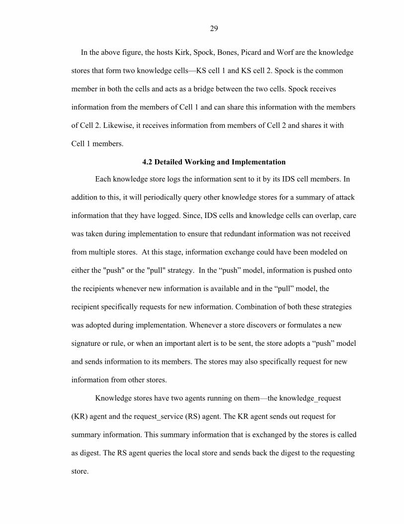
Figure 4-2 Communication sequence for digest request

31
Figure 4-2 depicts the sequence of communication and the steps taken to request
digest from a remote store.
1. Heartbeat sends event (digest request) E to coordinator;
2. Coordinator matches event E with rule-base;
3. Coordinator triggers KR agent;
4. KR agent sends digest request query Q to local communicator;
5. Local communicator parses query Q and sends it to remote communicator;
6. Remote communicator sends query to its coordinator;
7. Remote coordinator matches query Q with its rule-base;
8. Remote coordinator triggers RS agent;
9. RS agent queries its local store;
10. RS agent sends digest to KR agent.
Knowledge Digest. A digest is a short description of the alerts registered by a
knowledge store. Digest represents a unit of information that is sent between the
knowledge stores. It contains information such as the name of the alert, its type, the
reporting store and time it was detected. Since different stores may have different local
time, each store will have to send its current timestamp when it registers with other
members of the knowledge cell. Each knowledge store in the cell will compare the
timestamp with that of its own and will maintain a table with the difference in the
timestamps of other members. Thus a knowledge store will be able to arrange the events
it receives from different stores in near chronological order.
Periodically each store will receive a request for digest. The requesting agent will
also specify a timeframe (based on the time at remote store). A digest is then created and
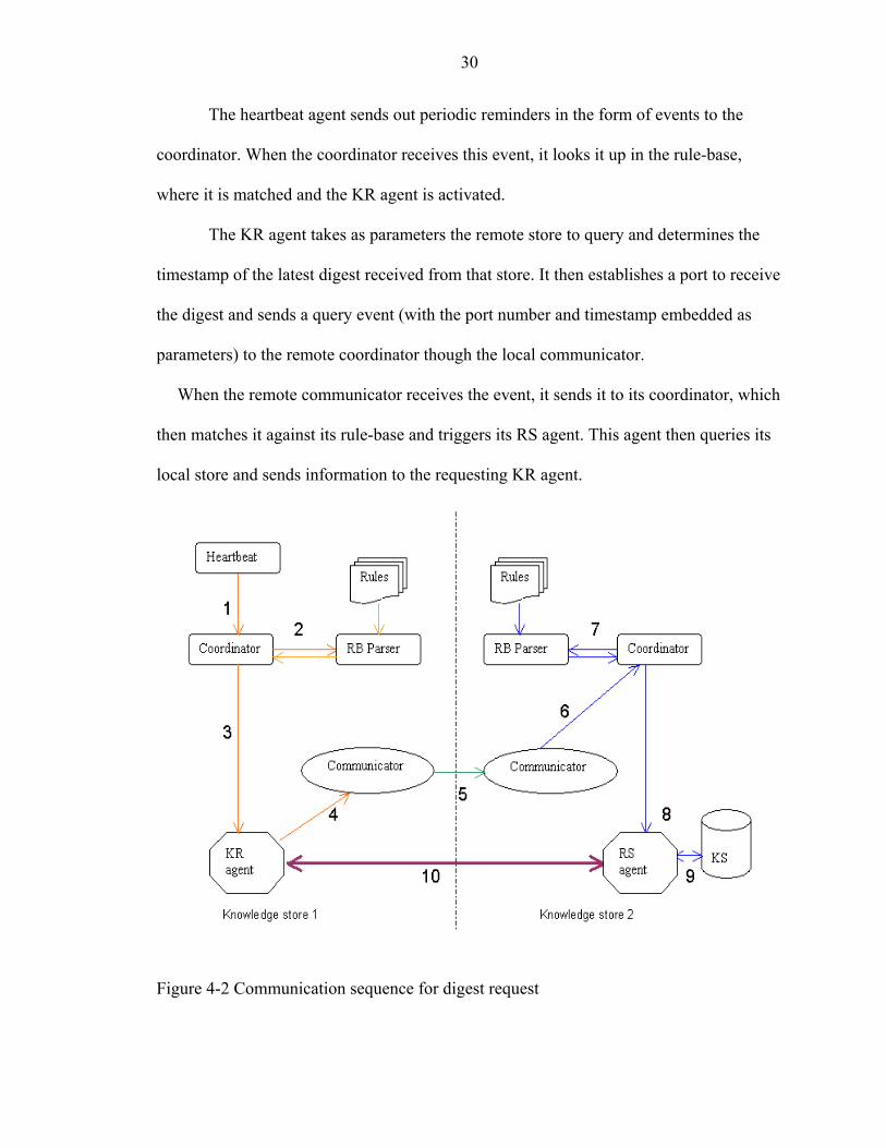
32
sent to the requesting agent. For example, the following table depicts a digest from a
store, Spock, to another store, Kirk.
Table 4-1. Sample digest from Spock to Kirk Alert Store Start Time End Time No.
Alerts DOS Land attack 128.227.179.35 20020712155940 20020712161709 21 DATA ON SYN detection 128.227.179.35 20020712155940 20020712161709 11 ICMP superscan echo 128.227.179.35 20020712151548 20020712152814 9 WEB-MISC prefix-get // 128.227.179.35 20020712155954 20020712161652 10 NETBIOS NT NULL session
128.227.179.35 20020713160355 20020713161413 16
SCAN Proxy attempt 128.227.179.35 20020713160355 20020713161854 12 INFO - Possible Squid Scan
128.227.179.35 20020713160358 20020713161917 6
WEB-IIS cmd.exe access 128.227.179.35 20020713160405 20020713162136 20
4.3 Using Digest from Remote Stores
The receiving agent maintains a table where it stores the digests it receives from other
remote stores. This information may be used by the system to perform data analysis such
as finding correlations between occurrences of different alerts, behavior of the black-hat
community, validating against false positives or may be used to take pro-active measures.
For instance, the IDS may shut down certain services in response to information
that another part of the network is being subjected to attacks against that service. An IDS
may find common attack patterns detected in multiple stores and use it to formulate rules
for the detection of the new attack
4.4 Database Schema
In order to implement the knowledge store, a relation database was used to store the
data and information relevant to the operation of the system. An existing schema for
Snort [25], a lightweight intrusion detector, was changed and adapted to facilitate the

33
broader requirements for information sharing. Information is stored in form of tables in
the database. The relational database MySql was used to create and store the tables
required for the IDS. Appendix at the end provides descriptions for few of the important
tables used in the system.
4.5 Querying for More Specific Information
Besides the information contained in the digest, which a store receives periodically, an
agent in the knowledge cell may also request for more specific information. Some of the
information that might be requested and for which support has been provided is listed
below.
• What host detected a particular attack/alert?
• Which detector on the host reported the attack/alert?
• What are the parameters reported (dependent on the detector deployed on the host)?
• What rule was activated?
• What response agent was triggered?
• What was the packet payload?
• What was the packet header information?
4.5.1 Message Format for Requesting Information
A knowledge store receives information about activities that have occurred at another
cell through digests. Each member of the IDS cell has access to this information that is
collected by its knowledge store. In addition to this digest that is periodically exchanged
between the stores, knowledge stores or agents acting on their behalf can request for
additional specific information. In order to request for such specific information, the

34
agent or the store will send a formatted request called as query to the remote store. The
query is made up of these four parts:
• Header information to route it to the right knowledge store or remote host; • Rule-base information; • Value fields; • Filter.
Header information. This consists of the address of the remote host and the port
number to send the message to. The communicator module parses and strips this
information off and sends the rest of the query to the remote host addressed in the header.
Rule-base information. This part of the query contains the information required
by the rule-base of the remote host to activate the knowledge_query agent that retrieves
the required data from its store
Value fields. This field specifies the names of the parameters whose values are
requested. This includes IP, ALERT, PAYLOAD, RULE, RESPONSE and other names
of the parameters reported by the detectors.
Filter values. This field specifies the filter that is to be applied to the query.
4.5.2 Format of Query
^dest:remote_host_IP:port^^BEGIN QRY requesting_host_name knowledge_query
(header info) (rule-base info)
select_values [list of parameters required] filter [filter values] END;
(value fields) (filter values)
4.5.3 Examples of Query
• Host Kirk requests Spock for list of all hosts that have logged any alert that contain the text ‘LAND’ in them:
35
^dest:spock_IP:55^^BEGIN QRY kirk_ip knowledge_query select_values [IP] filter [ALERT=’%LAND%’] END; • Host Kirk requests host 128.227.179.40 for source IP address, IP flags and TCP
destination port and packet payload information of all alerts logged by it with the text ‘LAND’ in them:
^dest:128.227.179.40:55^^BEGIN QRY kirk_ip knowledge_query select_values [IPHDR.IP_SRC, IPHDR.IP_FLAGS, TCPHDR.TCP_DPORT, PAYLOAD] filter [ALERT=’%LAND%’] END;
4.6 Applications of Knowledge Sharing
The following section describes some of the applications of knowledge sharing as
supported by the current implementation of the system.
4.6.1 Learning New Attacks
Since each knowledge store now has access to data from different hosts, it can use it to
detect new patterns of activities that indicate intrusive behavior. It can also detect
coordinated attacks that take place across different hosts. A dedicated agent may be
configured to run on the knowledge store that employs data-mining and other techniques
to uncover new patterns and use it to automatically form new signatures to detect it. If
such data-analyzing agents are also distributed with the knowledge stores, and since
knowledge stores essentially share data and information with each other, many agents
will be able to simultaneously detect coordinated attacks as opposed to a single entity in a
system detecting such an attack. Thus knowledge sharing creates a distributed awareness
of network activity.
4.6.2 Automatically Update New Signatures and Rules
When a knowledge store has a new signature or rule, it can actively share it with other
stores. When a store forms a new signature or rule, it will send the signature to its
member stores. The member stores record these signatures (which are detector specific)
in a separate table. The stores will then send an event to all their IDS member hosts about
36
the availability of new signatures. Each individual IDS will then choose to either accept
or reject the signature based on the rules specified in their rule files and based on whether
or not they are running the particular detector.
It was felt that instead of forcing all the members to accept the new signature, the
choice of whether or not to accept these signatures should be placed with each member
IDS. This is specified in their rule-base. The rules can also specify the signatures from
which particular host is to be accepted.
4.6.3 Reacting to Attacks
IDSs log the agents they activate in response to perceived threats or attacks. They also
log response agent specific parameters with the knowledge store. Other hosts in the
knowledge network may use this information to fine-tune their response to similar
attacks. It lays down the groundwork that will be necessary when mobile response agents
are added to the system.
4.6.4 Recovery from Failures
The knowledge stores log important information about their member IDSs that can be
used to recover from failures. The detectors currently deployed by the member IDS, the
response agents that are currently active, configuration information, and other such
information, are stored in the knowledge stores. On failure, other members in the cell can
elect to take over the functions of the failed member. Also, when a member is restarted
after failure, it can reload the information from the knowledge store and continue
functioning from where it left off. As another security feature, the knowledge store stores
MD5 hashes of the configuration files, rule file and the signature files. If a host is
compromised and the IDS on it is killed; and when the IDS is restarted, it can perform a
self-diagnostic check to see if any of its rule, signature or configuration files have been

37
changed. If it has been changed, it may choose to notify the administrator in a pre-
configured manner.
4.6.5 Take Pro-active Measures
Based on the information a store receives from its member stores, a data-analyzing
agent on it may choose to have the IDS members reconfigured in a pro-active manner.
For example, when a subnet in an organization sees attempts to exploit its FTP service,
other subnets in that organization may choose to have their FTP service turned off for a
while or block connection to the particular offending IP. Though, such automated data-
analyzing agents have not yet been implemented, the framework and the basic tools
required to perform the activity manually have been implemented.
4.7 Summary
This chapter described the framework for information sharing in the DGIDEM. It
introduced the concept of knowledge stores for the architecture and described the creation
of a large-scale, global, distributed knowledge base. The tools and features provided to
query remote knowledge stores was also presented. By having discrete, independent data-
analyzers that cooperate and exchange information with each other, a reliable, fault-
tolerant architecture can be created that has access to a large knowledge base.
CHAPTER 5 CONCLUSION AND FUTURE WORK
5.1 Conclusion
A framework for sharing knowledge with distributed, independent components of the
architecture was created. A flexible querying facility was also provided to enable specific
information to be requested from remote stores. The implementation allowed new
signatures and rules to be shared with other members of the network. Important alerts
were quickly propagated through the system; enabling other IDSs in the network to take
pro-active stance against impending attacks.
The knowledge stores also acted as back-up logging units, maintaining a copy of the
alerts registered by the individual IDSs. This allowed each IDS registered with it to
perform integrity checks after failures.
Knowledge stores aggregate information from several IDSs and provide an interface
for sharing and exchanging knowledge with other similar units. It is felt that such an
arrangement would scale better and would be easier to manage than having every single
IDS share information with each other directly.
Knowledge sharing was incorporated into the DGIDEM architecture and performed
well with the existing setup
5.2 Future Work.
The knowledge stores provide a dynamic data-source, but do not perform data
analysis. As of current implementation, the framework provides the tools to aid an
administrator to perform informed decisions. Additional agents can be built on top of the
38
39
existing architecture that automatically mine the data to detect new attacks, formulate
signatures and present them to the system for distribution.
All communications take place through the communicator module of the architecture.
Encryption and decryption functionalities should be added to this module. The inter-
component messaging mechanism can be modified to XML format as specified in CIDF
[8].
A user interface with capability to configure local and remote components of the
system needs to be developed. A performance-analysis module added to the user-
interface would be helpful.
APPENDIX KNOWLEDGE STORE TABLES
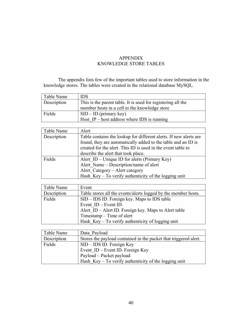
The appendix lists few of the important tables used to store information in the knowledge stores. The tables were created in the relational database MySQL. Table Name IDS Description This is the parent table. It is used for registering all the
member hosts in a cell to the knowledge store Fields SID – ID (primary key)
Host_IP – host address where IDS is running Table Name Alert Description Table contains the lookup for different alerts. If new alerts are
found, they are automatically added to the table and an ID is created for the alert. This ID is used in the event table to describe the alert that took place.
Fields Alert_ID – Unique ID for alerts (Primary Key) Alert_Name – Description/name of alert Alert_Category – Alert category Hash_Key – To verify authenticity of the logging unit
Table Name Event Description Table stores all the events/alerts logged by the member hosts. Fields SID – IDS ID. Foreign key. Maps to IDS table
Event_ID – Event ID. Alert_ID – Alert ID. Foreign key. Maps to Alert table Timestamp – Time of alert Hask_Key – To verify authenticity of logging unit
Table Name Data_Payload Description Stores the payload contained in the packet that triggered alert. Fields SID – IDS ID. Foreign Key
Event_ID – Event ID. Foreign Key Payload – Packet payload Hash_Key – To verify authenticity of the logging unit
40
41
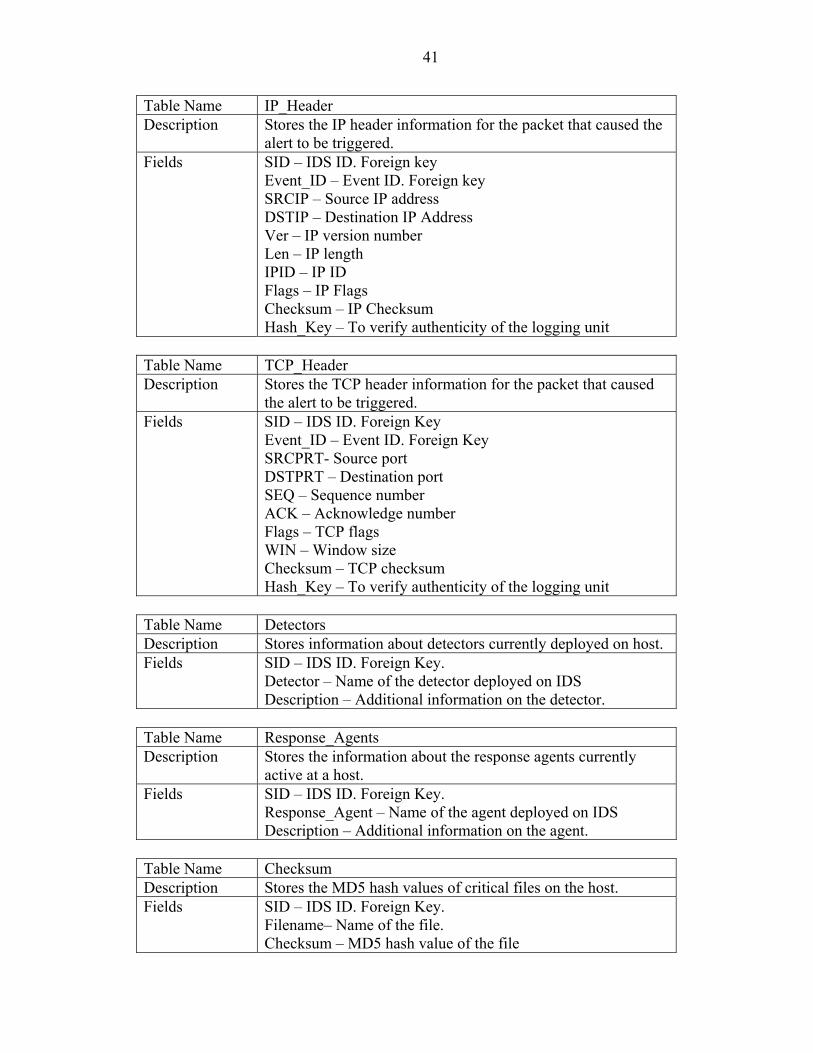
Table Name IP_Header Description Stores the IP header information for the packet that caused the
alert to be triggered. Fields SID – IDS ID. Foreign key
Event_ID – Event ID. Foreign key SRCIP – Source IP address DSTIP – Destination IP Address Ver – IP version number Len – IP length IPID – IP ID Flags – IP Flags Checksum – IP Checksum Hash_Key – To verify authenticity of the logging unit
Table Name TCP_Header Description Stores the TCP header information for the packet that caused
the alert to be triggered. Fields SID – IDS ID. Foreign Key
Event_ID – Event ID. Foreign Key SRCPRT- Source port DSTPRT – Destination port SEQ – Sequence number ACK – Acknowledge number Flags – TCP flags WIN – Window size Checksum – TCP checksum Hash_Key – To verify authenticity of the logging unit
Table Name Detectors Description Stores information about detectors currently deployed on host. Fields SID – IDS ID. Foreign Key.
Detector – Name of the detector deployed on IDS Description – Additional information on the detector.
Table Name Response_Agents Description Stores the information about the response agents currently
active at a host. Fields SID – IDS ID. Foreign Key.
Response_Agent – Name of the agent deployed on IDS Description – Additional information on the agent.
Table Name Checksum Description Stores the MD5 hash values of critical files on the host. Fields SID – IDS ID. Foreign Key.
Filename– Name of the file. Checksum – MD5 hash value of the file
42
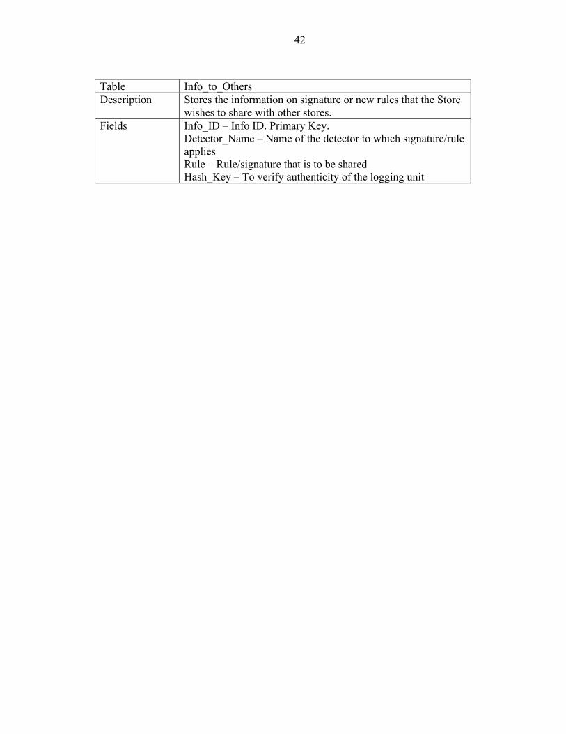
Table Info_to_Others Description Stores the information on signature or new rules that the Store
wishes to share with other stores. Fields Info_ID – Info ID. Primary Key.
Detector_Name – Name of the detector to which signature/rule applies Rule – Rule/signature that is to be shared Hash_Key – To verify authenticity of the logging unit

43
The following diagrams depict the relationships between the tables.
Figure A-1 Simplified database relationship diagram
LIST OF REFERENCES
[1] D. Anderson, T. Frivold, and A. Valdes. Next-generation intrusion detection expert system (NIDES). Technical Report SRI-CSL-95-07, Computer Science Laboratory, SRI International, Menlo Park, CA May 1995. [2] J.P. Anderson. Computer security threat monitoring and surveillance. Technical Report, James P. Anderson Co., Fort Washington, PA, February 1980. [3] J.S Balasubramaniyan, J.O. Garcia-Fernandez, D. Isacoff, E. Spafford, and D. Zamboni. An architecture for intrusion detection using autonomous agents. In Proceedings of the Fourteenth Annual Computer Security Applications Conference, pages 13–24. IEEE Computer Society, December 1998. [4] J. Barrus and N.C. Rowe. A distributed autonomous-agent network-intrusion detection and response system. In Proceedings of Command and Control Research and Technology Symposium, Monterey, CA, pages 577–586, June 1998. [5] T. Bass. Intrusion detection systems and multisensor data fusion: Creating cyberspace situational awareness, Communications of the ACM, 43(4):99-105, April 2000. [6] M. Crosbie, E. Spafford. Defending a computer system using autonomous agents. In Proceedings of the 18th National Information Systems Security Conference, 2:549-558, October1995. [7] M. Crosbie, G. Spafford. Active defense of a computer system using autonomous agents. Technical Report 95-008, COAST Group, Purdue University, February 1995. [8] D. Curry and H. Debar. Intrusion detection message exchange format data model and extensible markup language (xml) document type definition. Internet Draft, draft-ietf-idwg-xml-03.txt, February 2001. [9] D. Denning. An intrusion-detection model. IEEE Transactions on Software Engineering, SE-13(2):222–232, February 1987. [10] R. Feiertag, S. Rho, L. Benzinger, S. Wu, T. Redmond, C.Zhang, K. Levitt, D. Peticolas, M. Heckman, S. Stainford-Chen and J.McAlerney. Intrusion detection inter-component adaptive negotiation. Computer Networks, 34:605-621, 2002. [11] B.S. Feinstein, G.A. Matthews, and J.C.C. White. The intrusion detection exchange protocol (IDXP). Internet Draft draft-ietf-idwg-beep-idxp-02.txt, March 2001.
44
45
[12] D. Frincke, D. Tobin, J. McConnell, J. Marconi, and D. Polla. A framework for cooperative intrusion detection. In Proceedings of the 21st National Information Systems Security Conference, pages 361-373, October 1998. [13] A. Gandre. Implementation of a policy-based intrusion detection system - Generic intrusion detection model (GIDEM). Master’s thesis, University of Florida, Gainesville, Florida, 2001. [14] R. Gopalakrishna, E.H. Spafford. A framework for distributed intrusion detection using interest driven cooperating agents. Technical report 2001-44, CERIAS, Department of Computer Sciences, Purdue University, West Lafayette, IN, May 2001. [15] L. Heberleing, G. Dias, K. Levitt, B. Mukherjee, J. Wood, and D. Wolber, A network security monitor. In Proceedings of the 1990 IEEE Symposium on Research in Security and Privacy, pages 296-304. IEEE, IEEE Computer Society Press, Los Alamitos, CA, 1990. [16] K. Ilgun, R.A. Kemmerer, and P.A. Porras. State transition analysis: A rule-based intrusion detection approach. IEEE Transaction on Software Engineering, 21(3):181-199, March 1995. [17] D.J. Ingram. Autonomous agents for distributed intrusion detection in a multi-host environment. Master’s thesis, Naval Postgraduate School, Monterey, CA, September 1999. [18] Y.F. Jou, F. Gong, C. Sargor, S. Felix Wu, and C. Rance. Architecture design of a scalable intrusion detection system for the emerging network infrastructure. Technical Report CDRL A005, Dept. of Computer Science, North Carolina State University, Releigh, NC, April 1997 [19] A. Karkera. Implementation of a policy-based intrusion detection system –Distributed generic intrusion detection model (DGIDEM). Master’s thesis, University of Florida, Gainesville, Florida, December 2002. [20] S. Kumar. Classification and detection of computer intrusions, PhD thesis, Purdue University, West Lafayette, IN, August 1995. [21] W. Lee, R.A. Nimbalkar, K.K. Yee, S.B. Patil, P.H. Desai, T. Tran, and S.J. Stolfo. A data mining and CIDF based approach for detecting novel and distributed intrusions. In Proceedings of 3rd International Workshop on the Recent Advances in Intrusion Detection, No. 1907, pages 49-65, October 2000. [22] P.A. Porras and P.G. Neumann. EMERALD: Event monitoring enabling responses to anomalous live disturbances. In Proceedings of National Information Systems Security Conference, pages 353-365, Oct 1997.
46
[23] S.E. Smaha. Haystack: An intrusion detection system. In Proceedings of the IEEE Fourth Aerospace Computer Security Applications Conference, pages 37-44, Orlando, FL, December 1988. [24] S.R Snapp, S.E. Smaha, D.M. Teal, and T. Grance. The DIDS (distributed intrusion detection system) prototype. In Proceedings of the Summer USENIX Conference, USENIX Association, San Antonio, Texas, pages 227-233, June 1992. [25] SNORT, The open source network intrusion detection system. URL: http://www.snort.org, Date accessed: July 2002. [26] E.H. Spafford and D. Zamboni. Intrusion detection using autonomous agents. Computer Networks, 34(4), pages 547–570, October 2000. [27] S. Staniford-Chen, S. Cheung, R. Crawford, M. Dilger, J. Frank, J. Hoagland, K. Levitt, C. Wee, R. Yip, and D. Zerkle. GrIDS-a graph based intrusion detection system for large networks. In Proceedings of the 19th National Information Systems Security Conference, 1:361-370, September 1996. [28] TRIPWIRE, A policy driven file system integrity checker. URL: http://www.tripwire.com, Date accessed: July 2002. [29] J. Yang, P. Ning, X.S. Wang, and S. Jajodia. CARDS: A distributed system for detecting coordinated attacks. In Proceedings of IFIP TC11 Sixteenth Annual Working Conference on Information Security, pages 171-180, Aug 2000. [30] G. White and V. Pooch. Cooperating security managers: Distributed intrusion detection system. Computers and Security, 15(5):441-450, 1996.
BIOGRAPHICAL SKETCH
Muruga B. Chengalvarayan was born in the Bangalore, the Garden city of India. He
received his Bachelor of Engineering degree in computer science and engineering from
the University of Madras, India, in May 2000. He received his master’s degree in
computer engineering from the University of Florida, Gainesville, in December 2002. His
research interest includes computer networks and network security
47