kolam: a cross-platform architecture for scalable...
TRANSCRIPT
KOLAM: A cross-platform architecture for scalablevisualization and tracking in wide-area imagery
Joshua Fraser*, Anoop Haridas*, Guna Seetharaman†, Raghuveer M. Rao‡,Kannappan Palaniappan*
*Dept. of Computer Science, University of Missouri, Columbia, MO 65211, USA†Air Force Research Laboratory, Rome, NY 13441, USA‡Army Research Laboratory, Adelphi, MD 20783, USA
ABSTRACT
KOLAM is an open, cross-platform, interoperable, scalable and extensible framework supporting a novel multi-scale spatiotemporal dual-cache data structure for big data visualization and visual analytics. This paper focuseson the use of KOLAM for target tracking in high-resolution, high throughput wide format video also known aswide-area motion imagery (WAMI). It was originally developed for the interactive visualization of extremely largegeospatial imagery of high spatial and spectral resolution. KOLAM is platform, operating system and (graphics)hardware independent, and supports embedded datasets scalable from hundreds of gigabytes to feasibly petabytesin size on clusters, workstations, desktops and mobile computers. In addition to rapid roam, zoom and hyper-jump spatial operations, a large number of simultaneously viewable embedded pyramid layers (also referred toas multiscale or sparse imagery), interactive colormap and histogram enhancement, spherical projection andterrain maps are supported. The KOLAM software architecture was extended to support airborne wide-areamotion imagery by organizing spatiotemporal tiles in very large format video frames using a temporal cache oftiled pyramid cached data structures. The current version supports WAMI animation, fast intelligent inspection,trajectory visualization and target tracking (digital tagging); the latter by interfacing with external automatictracking software. One of the critical needs for working with WAMI is a supervised tracking and visualizationtool that allows analysts to digitally tag multiple targets, quickly review and correct tracking results and applygeospatial visual analytic tools on the generated trajectories. One-click manual tracking combined with multipleautomated tracking algorithms are available to assist the analyst and increase human effectiveness.
Keywords: wide-area motion imagery, WAMI, digital tagging, assisted tracking, trajectory visualization, tra-jectory data mining, spatiotemporal cache, multiresolution tiled pyramid imagery
1. INTRODUCTION
Exploratory visualization and analytics tools are powerful methods to support multiple data-streams and navigatethrough very large datasets. Such tools offer ways to mitigate the data deluge1 being faced by users and analystsand are useful for providing insight into complex patterns in scientific, biomedical, geospatial, satellite, andsurveillance applications. In the intelligence, surveillance and reconnaissance (ISR) community the massive dataproblem is popularly paraphrased as “Swimming in sensors, drowning in data”2 to convey the increasing urgencyof this problem with respect to processing the flood of airborne video from defense surveillance assets. KOLAM(K-tiles for Optimized muLtiresolution Access with coMpression)3,4 is a scalable and extensible framework forhigh-resolution, high throughput image data visualization with applications in a variety of image analysis domainsincluding WAMI.5 It is platform and operating system independent and supports embedded datasets scalablefrom hundreds of gigabytes to potentially petabytes in size on architectures ranging from clusters to netbooks.KOLAM uses a scalable data structure and dual cache management strategies to support large datasets alongwith an extensive set of image processing and analysis features. Robust animation and novel tracking interfacesare available to enable smooth animation of WAMI sequences and support one-click per frame tracking of objects.KOLAM is capable of interfacing with different tracking algorithms and visualizing the resulting trajectories thatmay be composed of multiple segments. Figure 1 shows the coupling between the visualization environment andthe open architecture supporting a collection of tracking algorithms. A feature-rich tracking interface enables
Geospatial InfoFusion III, edited by Matthew F. Pellechia, Richard J. Sorensen,Kannappan Palaniappan, Proc. of SPIE Vol. 8747, 87470N · © 2013 SPIE
CCC code: 0277-786X/13/$18 · doi: 10.1117/12.2018162
Proc. of SPIE Vol. 8747 87470N-1
Downloaded From: http://proceedings.spiedigitallibrary.org/ on 06/17/2013 Terms of Use: http://spiedl.org/terms

Image and TrackVisualization Tools
GPU & C ++
Figure 1. KOLAM is part of an open environment for visualization and target tracking supporting interfacing to severaltracking algorithms and exchanging track files with multiple visualization tools.
simultaneous visualization of multiple tracks, context-sensitive track operations, track archival and retrieval,moving object ground truth generation, track editing and annotation.
In this paper we focus on the application of KOLAM to the visualization and analysis of WAMI datasets whichare extremely large gigapixel-sized video frames with high spatial resolution and low frame rates of typically oneto ten frames per second. WAMI sensors typically consist of an airborne camera array with electro-optical,infrared or multispectral sensors being used to acquire a wide spatial field of view in persistent observation modeas illustrated pictorially in Figure 2. There are a number of defense and commercial applications for WAMIranging from surveillance and law enforcement to crop or infrastructure monitoring and emergency response.The rays in Figure 2 indicate the ground projection of tall structures that generate significant parallax inducedmotion proportional to the height of the building. Occluded rays are indicated by a black ground plane trajectoryand such obscurations between the platform and the ground need to be anticipated in tracking systems. There area number of challenges associated with acquiring and processing WAMI as detailed in recent publications.4–17
In addition to large data volumes, vision processing and exploitation challenges, other dissemination relatedchallenges in working with WAMI datasets include real-time downlink capability of full or partial video streams,shared on-board and ground-based processing to optimize data to decision, network-based video distribution ofmultiple regions of interest, managing thousands of targets and tracks, trajectory mining for patterns of life,etc. The need for user-driven models in the analysis of WAMI data to address difficult or unsolved problems inWAMI exploitation include: automated content-based search tools, a synergistic visual analytics tool for analysis,human-computer interaction that is capable of capturing user domain knowledge to improve productivity andsearch tools applied to multitarget tracking results. We describe the components of the KOLAM architectureand environment for accessing and visualizing WAMI.
2. RELATED WORK ON BIG DATA VISUALIZATION
Gigapixel-sized images have become much more prevalent over the past decade in a variety of domains includingmedicine, space, satellite and defense. Consequently, the development of tools for gigapixel-sized image visu-alization has been an active area of research. Figure 3 shows the ability to visualize large temporal satelliteimagery in KOLAM in a fashion similar to and building on the legacy of visualization techniques pioneered inthe NASA Interactive Image SpreadSheet (IISS) approach19–22 combined with scalable out-of-core methods.
Proc. of SPIE Vol. 8747 87470N-2
Downloaded From: http://proceedings.spiedigitallibrary.org/ on 06/17/2013 Terms of Use: http://spiedl.org/terms

Figure 2. An airborne camera array system is used to acquire WAMI imagery in persistent mode. The rays indicate theground projection of tall structures that generate significant parallax induced motion proportional to the height of thebuilding. Occluded rays, indicated by coloring the trajectory on the ground black, and other geometric obscurations area challenge for tracking systems. See color version of figure.
Figure 3. High resolution NASA EOS MODIS BlueMarble18 global mosaic time sequence showing a sample four monthsof seasonal changes. Each image is 86,400× 43,200 pixels in size, three channel RGB, and 500m pixel spatial resolution.
One key aspect of gigapixel visualization is display technology – single, multiple or tiled (wall-sized) displaysand balancing data movement, rendering, computation and caching without sacrificing interactivity using a col-lection of (multicore) processors, storage devices, network services, and display capabilities. Recent examplesusing a single display for creating, processing and displaying ultra-high resolution images with high dynamicrange and wide angle fields-of-view is work by Kopf et al.23 and Summa et al.24 Methods for systematicallyannotating and rendering both auditory and visual annotations in gigapixel imagery is described in.25 Addi-tionally, work has been done towards rapid post-processing of gigapixel imagery utilizing an efficient parallelprogramming methodology.26 Based on the ability of the human visual system to rapidly identify patterns anddiscern differences, especially when the targeted data is extremely large, extensive research has been performed
Proc. of SPIE Vol. 8747 87470N-3
Downloaded From: http://proceedings.spiedigitallibrary.org/ on 06/17/2013 Terms of Use: http://spiedl.org/terms

regarding the visualization of high-resolution imagery on tiled displays.27–38 Architectures such as SAGE29,33,38
and DIGI-Vis;37 and applications such as JuxtaView30 and Giga-Stack36 seamlessly display a number of visu-alization applications over the entire tiled display. The primary goal of such systems is to support applicationheterogeneity and scalability by decoupling the graphics rendering and display processes from each other, andby utilizing high-bandwidth lambda networks to bridge them. Such ultra large-scale visualization initiatives arecurrently being used with infrastructures such as the OptiPlanet Collaboratory.31,35 This persistent, distributedvisualization cyberinfrastructure connects a series of OptIPortals,34,35 which are tiled displays that comprisethe visual interfaces to OptIPuters.27,34 These large scale visualization and analysis systems seek to create asynergistic combination between dense displays, high-speed networking, remote storage containing extremelylarge scientific datasets, distributed processing, data mining and visualization.32 KOLAM supports a range ofdisplay technologies from single mobile displays to large hundred megapixel tiled wall-sized displays with suffi-cient computing resources to hide latencies and ensure seamless interactivity for the user. In this paper we focusprimarily on the general architecture, visualization and object tracking features in KOLAM.
3. LARGE DATA ORGANIZATION FOR WAMI
In order to efficiently manage the display of large time-varying imagery, each image is partitioned or tiled intosubimages or image blocks of the larger dataset using a quad-tree like regular tiling3,39 that is now widely used invisualization systems for images and meshes.25,26,36,37,40–46 These tiles allow random access to spatially coherentregions of the image and thus allow for on-demand access to those parts of the image needed for display as wellas application-level management of memory. While tiling the image at a single resolution allows for efficientaccess to the full resolution dataset, viewing the image in its entirety would require reading all tiles from disk. Inorder to provide interactive zooming of the image across scale, multiresolution tiling is used. Multidimensionaltiles or bricks can be used to organize large volumes and higher dimensional datasets similar to our descriptionfor 2D images.
3.1 Pyramidal Data Format for Motion Imagery
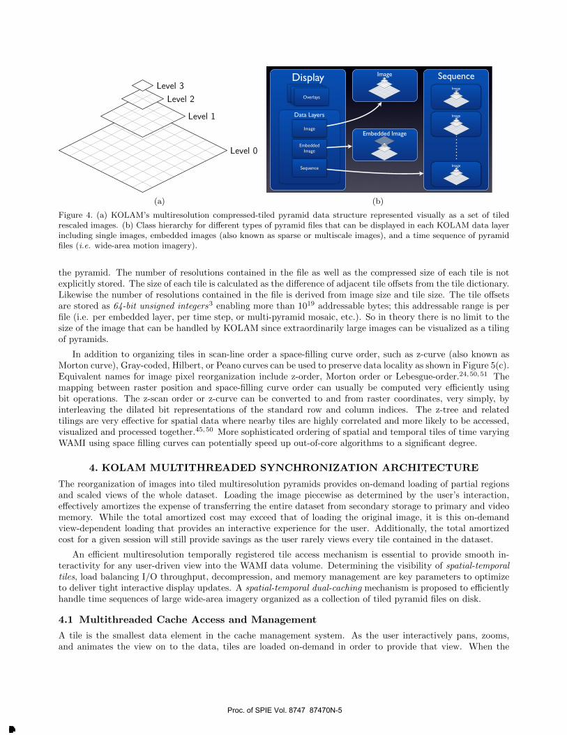
A multiresolution pyramid is created by scaling the image in half along each dimension like a quad-tree until aminimum size (i.e. single tile) is reached. Following successive scaling, each resolution is divided into fixed-sizedtiles. For our system, we’ve chosen fixed-resolution (compressed) tiles across all resolutions of the image. Thistiled multiresolution data organization creates a pyramidal structure for each frame in motion imagery as shownin Figure 4. Each scaling results in an image that is one-fourth the preceding level of the pyramid with the finestresolution at the lowest level of the pyramid. Although the total size of the pyramid is one-third larger thanthe original wide-area image,3 compressing individual tiles (lossy or lossless) across levels substantially reducesthe total file size. In addition to the scale-and-tile approach described here, an alternative approach is to usea tile-and-scale organization as in JPEG200047–49 or a hybrid scheme.3 KOLAM has support for multiple tiledpyramid image organization formats that continues to be extended.
Tiles can be individually compressed and a number of compression algorithms are currently supported in-cluding ZLIB, BZIP2, RLE, JPEG and JPEG2000. Compressing the individual tiles provides two advantages:alleviating the secondary-storage overhead of maintaining multiple resolutions, and improving I/O throughputfrom secondary-storage by requiring fewer bytes to be read than the raw uncompressed data. Lossless or highquality lossy formats are preferred because further analysis and processing such as automatic tracking will beperformed on faint, low-contrast, and small targets.
3.2 Pyramidal Disk File Format for Motion Imagery
The on-disk pyramid (.pyr) format of our multiresolution pyramid files contains a header identifying the fileand the image’s underlying structure including depth, dimensions, tile dimensions, and tile count (Figure 5(b)).Following this metadata is a dictionary mapping each image tile to its byte offset in the file. Compressed tiledata is located immediately following the header and tile dictionary. Organization of the tiles and specifics ofthe metadata are shown in Figure 5. The tiles in KOLAM pyramid files is organized and stored in sequentialscan-line order from finest to coarsest resolutions as shown in Figure 5(a), with the highest original resolutionnumbered as level zero (Figure 4). The tile dictionary contains just the byte offsets for each tile contained in
Proc. of SPIE Vol. 8747 87470N-4
Downloaded From: http://proceedings.spiedigitallibrary.org/ on 06/17/2013 Terms of Use: http://spiedl.org/terms
Level 0
Level 1
Level 2
Level 3
(a)
DisplayOverlaysOverlaysOverlays
Data Layers
Embedded Image
Image Sequence
Image
Sequence
Image
Embedded Image
Image
Image
(b)
Figure 4. (a) KOLAM’s multiresolution compressed-tiled pyramid data structure represented visually as a set of tiledrescaled images. (b) Class hierarchy for different types of pyramid files that can be displayed in each KOLAM data layerincluding single images, embedded images (also known as sparse or multiscale images), and a time sequence of pyramidfiles (i.e. wide-area motion imagery).
the pyramid. The number of resolutions contained in the file as well as the compressed size of each tile is notexplicitly stored. The size of each tile is calculated as the difference of adjacent tile offsets from the tile dictionary.Likewise the number of resolutions contained in the file is derived from image size and tile size. The tile offsetsare stored as 64-bit unsigned integers3 enabling more than 1019 addressable bytes; this addressable range is perfile (i.e. per embedded layer, per time step, or multi-pyramid mosaic, etc.). So in theory there is no limit to thesize of the image that can be handled by KOLAM since extraordinarily large images can be visualized as a tilingof pyramids.
In addition to organizing tiles in scan-line order a space-filling curve order, such as z-curve (also known asMorton curve), Gray-coded, Hilbert, or Peano curves can be used to preserve data locality as shown in Figure 5(c).Equivalent names for image pixel reorganization include z-order, Morton order or Lebesgue-order.24,50,51 Themapping between raster position and space-filling curve order can usually be computed very efficiently usingbit operations. The z-scan order or z-curve can be converted to and from raster coordinates, very simply, byinterleaving the dilated bit representations of the standard row and column indices. The z-tree and relatedtilings are very effective for spatial data where nearby tiles are highly correlated and more likely to be accessed,visualized and processed together.45,50 More sophisticated ordering of spatial and temporal tiles of time varyingWAMI using space filling curves can potentially speed up out-of-core algorithms to a significant degree.
4. KOLAM MULTITHREADED SYNCHRONIZATION ARCHITECTURE
The reorganization of images into tiled multiresolution pyramids provides on-demand loading of partial regionsand scaled views of the whole dataset. Loading the image piecewise as determined by the user’s interaction,effectively amortizes the expense of transferring the entire dataset from secondary storage to primary and videomemory. While the total amortized cost may exceed that of loading the original image, it is this on-demandview-dependent loading that provides an interactive experience for the user. Additionally, the total amortizedcost for a given session will still provide savings as the user rarely views every tile contained in the dataset.
An efficient multiresolution temporally registered tile access mechanism is essential to provide smooth in-teractivity for any user-driven view into the WAMI data volume. Determining the visibility of spatial-temporaltiles, load balancing I/O throughput, decompression, and memory management are key parameters to optimizeto deliver tight interactive display updates. A spatial-temporal dual-caching mechanism is proposed to efficientlyhandle time sequences of large wide-area imagery organized as a collection of tiled pyramid files on disk.
4.1 Multithreaded Cache Access and Management
A tile is the smallest data element in the cache management system. As the user interactively pans, zooms,and animates the view on to the data, tiles are loaded on-demand in order to provide that view. When the
Proc. of SPIE Vol. 8747 87470N-5
Downloaded From: http://proceedings.spiedigitallibrary.org/ on 06/17/2013 Terms of Use: http://spiedl.org/terms

0 1 2 3 4 5 6 7
8 9 10 11 12 13 14 15
16 17 18 19 20 21 22 23
24 25 26 27 28 29 30 31
32 33 34 35 36 37 38 39
40 41 42 43 44 45 46 47
48 49 50 51 52 53 54 55
56 57 58 59 60 61 62 63
Level 0
64 65 66 67
68 69 70 71
72 73 74 75
76 77 78 79
Level 1
80 81
82 83
Level 2
84
Level 3
(a)
HeaderMagic String string; “KOLAM”Compression string; “ZLIB0”Image Width unsigned 32 bit integerImage Height unsigned 32 bit integer
Bytes per Pixel unsigned 32 bit integerTile Width unsigned 32 bit integerTile Height unsigned 32 bit integerTile Count unsigned 32 bit integer
Tile DictionaryCompressed Tile Data
(b)
0 1
2 3
4 5
6 7
8 9
10 11
12 13
14 15
16 17
18 19
20 21
22 23
24 25
26 27
28 29
30 31
32 33
34 35
36 37
38 39
40 41
42 43
44 45
46 47
48 49
50 51
52 53
54 55
56 57
58 59
60 61
62 63
Level 0
64 65
66 67
68 69
70 71
72 73
74 75
76 77
78 79
Level 1
80 81
82 83
Level 2
84
Level 3
(c)
Figure 5. (a) Pyramid tile organization in raster scan-line order for a four-level hierarchy starting with 8 × 8 tiles. (b)Metadata structure of the KOLAM pyramid image file format header for storing all tiles across all resolutions within asingle image file. (c) Pyramid tile organization in z-scan or Morton scan ordering for the same four-level hierarchy thatimproves spatial locality.
cache management subsystem in KOLAM determines that an unavailable tile is needed in order to fulfill anyuser-requested view, a tile access cache-request is generated and queued. This request is handled asynchronouslyby a separate thread to prevent any I/O blocking from interrupting the interactivity of the user interface anddisplay event loop. To achieve this asynchronous behavior, two types of threads are used: one display thread foruser interaction and display, and multiple read threads to fulfill tile requests from disk. The number of threadsis variable and can be tuned for different systems. Thread cooperation behaviors are shown in Figure 6.
The display thread, Figure 6(b), is responsible for user interaction, determining which tiles are necessary toprovide the current view of the data, and drawing the view as tiles become available (with or without displaybuffering). The display thread transforms the current view requirement to a set of tile requests. Mapping thecurrent view to the underlying data is dependent on spatial position, scaling, and current time. The view istracked in a global coordinate system with respect to the finest resolution of the pyramid and sequence order ofthe time-varying data. Uniquely identifying a tile in the system requires that each tile be first associated withits temporal index (mapped from time to a file), and then spatially within the pyramid structure.
When tiles associated with the current view are resident in cache and the system load is light, KOLAM willpredict what will be needed in the near future based on current user behavior and generate requests for thisdata in advance. Preloading data is necessary to fulfill the user’s expectation of interactivity; failure to fill theview within tens of milliseconds may cause portions of the view to remain blank or out-of-date. Prefetchingoccurs both temporally with respect to the time sequence, and also spatially by pre-loading tiles surrounding thecurrent view. Spatial prefetching attempts to predict tiles that will soon be required to fill the display for thecurrent time index. Scheduling tiles to be loaded immediately adjacent to the current view, but not yet resident,allows the system to anticipate future view requirements and ensure that needed data is available in the cache ina timely fashion. Temporal prefetching determines which frames of the sequence will be needed (and when) inorder to ensure that the associated pyramids are available in the (temporal) frame buffer, and to issue requests
Proc. of SPIE Vol. 8747 87470N-6
Downloaded From: http://proceedings.spiedigitallibrary.org/ on 06/17/2013 Terms of Use: http://spiedl.org/terms

SynchronizedAccess
Request Queue
DisplayThread
ReaderThread
ReaderThread
Tile Cache
Tile Request
Tile
Tile Request
Tile
(a)
DetermineNext Tile
Tile inCache?
Get CachedTile
Draw Tile
RequestQueue
Request Tile Tile Cache
yes
no
(b)
Wait Tile Cache
QueueEmpty?
Get RequestGet
CandidateTile
ReadCompressed
Tile
Process &Decompress
TileCheck-In Tile
RequestQueue File
yes
no
(c)
Figure 6. (a) Multithreaded synchronization of display and reader (worker) threads in KOLAM. (b) Display threadinteractions with Request Queue and Tile Cache. (c) Reader thread interactions with Request Queue and Tile Cache.
for tiles that will be needed in the next time step.
Under heavy system load, the demands of the view may exceed the ability of threads to deliver data. Com-promises must be made to provide a seamless experience for the user. Spatially, rather than allow blank regionsor out-of-date data to be displayed, a consistent view can be presented by progressively loading coarser tileswhen tiles at the current resolution are not yet available. Temporally, rather than playing back the anima-tion too slowly, the system should attempt to fulfill the user’s expectations of interactivity by dropping frames.These compromises affect only the display component of KOLAM and not the tracking subsystems which haspredictable access patterns and utilizes the full spatiotemporal resolution data.
Reader threads (Figure 6(c)) provide asynchronous delivery of tiles to the spatial-temporal tile cache. Initiallya reader thread is in a wait state. The thread waits on a POSIX condition until there are tile requests in thequeue. When the request queue is no longer empty, reader threads are awakened to retrieve requests from thequeue and service those requests. When the thread has completed the task of delivering a tile to the tile cache,it either continues with the next request in the queue or returns to the wait state if the request queue is empty.
Reader threads are responsible for fulfilling the three phases of a tile request: reading, decompressing, andcaching the tile in primary memory. The first phase of fulfilling a tile request is to find memory within thecache to hold the result of the request. A centralized cache contains the collection of all tiles currently residentand provides storage for new tiles if the cache has not reached its predetermined maximum size. If the cacheis currently full, a candidate tile for replacement (removal) is chosen and checked out of the cache. Checkingout a tile transfers ownership of the tile’s memory to the thread and ensures that the tile scheduled for deletionis unavailable to other threads. The replacement tile can no longer be accessed by the display thread nor is itavailable to other reader threads until it is again checked back into the tile cache.
Once cache memory for a tile has been determined, the read phase begins. A requested tile is mapped fromits spatial-temporal index first to a file in the sequence, and then to a byte offset and size within the file using the
Proc. of SPIE Vol. 8747 87470N-7
Downloaded From: http://proceedings.spiedigitallibrary.org/ on 06/17/2013 Terms of Use: http://spiedl.org/terms

tile dictionary. Using this size and offset, a read system call is issued to the file to transfer the data from disk tomemory. This system call is intentionally a synchronous call which will block the current thread of execution–butnot other threads–until such time as the operating system can honor the request. The result of this read is acompressed tile which is saved into a thread-specific local buffer.
Once the compressed tile is available, the thread is then responsible for decompressing the tile. The tile isdecompressed from the thread read buffer into cache memory. The result of this decompression is a display-readytile located in the central tile cache. Following successful loading and decompression of a tile, the cache is notifiedof the presence of this new tile. The check-in of this tile serves two purposes: transferring ownership of the tile’smemory back to the system for reuse and notifying the display thread that new data is ready for display.
4.2 Thread Synchronization and Load Balancing
Synchronization of threads is necessary when accessing two structures: the request queue and the spatial cache.This synchronization process shown in Figure 6(a) ensures that access to these protected structures is serializedamongst multiple competing threads. Sychronization is provided using POSIX mutex variables and conditions.
Coordination of tasks amongst the threads is provided by a workpile concurrency model. Tasks (in this casetile requests) are placed in a first-in-first-out request queue by the display thread. Threads retrieve requestsfrom this queue in order to fetch tiles for delivery into the spatial-temporal tile cache. As previously describedKOLAM uses synchronous blocking reads when fetching compressed tile data. The purpose of blocking reads isto achieve load balancing between I/O and processing. Blocking reads provide a yield point for the executing readthreads. When a read from disk is requested to the operating system, the thread will block yielding executionto other threads until that transfer from disk is available. While one thread is blocking on the read system call,other threads can utilize the CPU for processing and decompression. This workpile model is well suited for thenature of KOLAM’s I/O and CPU intensive demand patterns for the visualization of large tiled motion imagery.
4.3 Spatial-Temporal Dual-Caching Tile Organization
Motion imagery requires coherent caching both spatially and temporally. To determine temporal caching of tilesas the view varies in time requires knowledge of the next frame in time which may not be immediately adjacentin the sequence. As an investigative tool, simple sequential linear playback of the data may be insufficient forthe demands of the user. The playback sequence of frames may occur in a cyclic pattern as opposed to justclamped from the beginning to the end of the sequence. Looping and rocking playback are examples of thiscyclical pattern. The user should also be able to play the animation both forwards and in reverse at a specifiedframe rate. Additionally, the user may wish to stride through the data in order to visualize long sequences morequickly by setting the step size.
Dual-caching is used to accommodate a sequence of files for animation. The first form of caching is at thetemporal file level to organize temporal information and the second form of caching is at the spatial level whichis discussed subsequently. Each frame in a sequence exists as a separate file. The cost of opening and parsing thefile’s header and generating the associated tile lookup tables requires that the results of this process be cached forfast access to the tile data. Additionally, because the length of a sequence can be very long, the entire sequenceof file pointers and associated pyramid data structures cannot all remain resident due to limited resources–bothwith respect to memory and also the maximum number of open file handles imposed by the operating system.To manage this two-tiered caching, a separate file buffer is maintained. This buffer is kept full based on playbackof time and the animation parameters set by the user. As the display updates time, this file buffer is keptup-to-date. When one frame of the sequence is removed from this buffer, a future frame is loaded from disk.At the time of this loading, no tile requests are actually issued, the file is only opened and parsed to build thenecessary structures for accessing the tiles. As a file is paged out of the animation buffer, the tiles associatedwith that file are marked for recycling. This recycling marks those tiles in the cache as immediately availablefor reuse by future tile requests.
It is important to note that the order of images in the resident file buffer may not be sequential or in increasingorder. Rather the buffer will reflect the parameters used for playback of the animation. For example, the usermay have chosen to loop a subset of the entire animation for playback with a negative stride. The cyclic nature
Proc. of SPIE Vol. 8747 87470N-8
Downloaded From: http://proceedings.spiedigitallibrary.org/ on 06/17/2013 Terms of Use: http://spiedl.org/terms

TáE
A=2
a=s A=7Blink
End
StartRestart / Pause
Clamp
fps =2 fps =4 fps =1
Rock
fps= 2 fps =1 fps =4
Cycle
User Interaction Time -!>
Figure 7. Sample ordering of frame sequences as a function of user interaction time showing four different user selectedplayback modes (top to bottom) including blinking between two closely or widely separated frames at different speeds,play through the loop once (clamp) with and without an intermediate pause, rocking back and forth at different framerates, and continuous looping at different rates. Scrubbing through the sequence and random frame access are not shown.
of playback (loop and rock) and the need to skip frames (stride or frame dropping) in the sequence creates a non-linear sequence of frames needed for playback. In order to properly preload and buffer frames of the sequence,the system must be able to properly predict those frames which will be drawn in the future. Toward this goal,the sequence of past and future frames is modeled as a function of time. For any given time, the system mustbe able to query what frame would be drawn at that time. By monitoring latencies to fulfill a view, the systemcan choose to load only the sequence of frames which can be successfully retrieved from disk.
This ability to determine only what will actually be available for display as opposed to what would be nextwithout the unavoidable latencies allows the system to manage its limited resources more effectively. Accuratelypredicting which frame to load based on playback speed and load time, the system can fill the caches withoutwasting precious resources on frames that will be skipped.
The various modes of playback can be modeled using clamped, sawtooth, and triangle functions as shownin Figure 7. These models are used both for preloading data as well as maintaining a temporally coherent filecache. During the preloading phase, the system examines the frame cache and requests tiles for the current viewat the next time. The next time is simply the span determined by the frame rate when the system is not underfull load and can reliably fulfill all data requests. When the system is under a full load, the next time is theaverage current latency of successfully filling the view as determined by the display.
We now elaborate on the second form of caching at the spatial tile level. Tiles in the cache are referenced totheir associated temporal frame in the animation sequence. A number of approaches can be considered for thetile replacement or tile paging strategy including random, minimum, First In First Out (FIFO), Not RecentlyUsed (NRU), Least Recently Used (LRU) and our proposed spatial multiresolution distance-based (SMD) tilereplacement or SMD tile paging. Similar to the classic operating system level paging strategy,52 the LRU tilepaging or replacement strategy chooses the oldest tile contained in the spatial tile cache to be swapped out for anew incoming tile. This approach is effective in that as the user zooms and pans the image, recently drawn tilesare likely to be needed again in the near future. The approach predicts that the least recently accessed tile willbe the best candidate for removal from the tile cache.
Proc. of SPIE Vol. 8747 87470N-9
Downloaded From: http://proceedings.spiedigitallibrary.org/ on 06/17/2013 Terms of Use: http://spiedl.org/terms

While the LRU approach is effective, and has been implemented in KOLAM, it ignores additional spatialinformation that can be used to improve upon the LRU tile replacement algorithm. Although the user can makelarge disconnected jumps from one view to another in the image, this is not the typical way in which usersvisualize and navigate large motion imagery. Rather, users tend to pan around the image and zoom in and outin order to inspect the data. The nature of this user interaction suggests that paging based on a tile’s distancefrom the current view rather than age of tiles would be more effective. Our preferred SMD tile paging strategyutilizes this spatial coherency to more efficiently manage the paging of the tile cache. Our approach is to keepall the tiles closest to the current view, and choose as replacement tiles those that are the furthest way in termsof spatial distance. A simple L1 or Manhattan distance metric is used to update the distance of each tile incache with respect to the current view. The result of this distance-based caching is a clustering of resident tilesnearest to the current view. When a new tile is requested and the cache is full, then the tile with the greatestdistance value is chosen for replacement.
5. KOLAM INTERFACE FOR VISUALIZATION AND TRACKING
KOLAM allows users to exploratively interact with and manipulate a time sequence of very large imageryin pyramid format or (same-sized) image files in common image formats including TIFF, PNG and JPEG.In addition to image visual analytics, KOLAM also supports the interactive visualization of extremely large,spatially and spectrally varying geospatial imagery rendered as a 3D globe. KOLAM uses the Qt applicationprogramming interface and GUI framework to provide interactive tracking and management of trajectories forWAMI datasets, as well as the ability to interface with and invoke external tracking algorithms. The remainderof this section describes interface elements pertaining to the visualization of information layers in KOLAM,followed by a description of the interface front-end and corresponding implementations for the animation andtracking subsystems.
5.1 Visualization of Multiple Layers of Analytic Information
KOLAM can simultaneously display and combine multiple layers of raster or vector information interactivelyto produce composite analytic visualizations using a layer selection interface. A layer is a high level visualrepresentation of a dataset that encapsulates both the image information and relevant metadata.39 It is possibleto simultaneously visualize multiple layers, and each layer may have one each of several types of viewers andnavigators associated with it. The user can interactively move a given layer up or down the layer-stack to controlits visibility and blending with regard to other visible layers. The regions of a given layer that are occludeddepends on its position in the overall layer-stack; this feature allows for rapid control of the visibility andoverall spatial composition of layers. Additionally, alpha blending enables exploratory visualization by combiningdifferent layers. The user can interactively switch between applying a global navigation transformation to affectall visible layers of information or apply a local transformation to align each layer image. This is useful forperforming interactive mosaicing and georegistration of large composite imagery.
5.2 Visualizing Motion Imagery
KOLAM provides a highly compact user interface via the KOLAM-Loop tool that comprehensively addressesuser needs when playing back WAMI and other image sequences. KOLAM supports playback of a given sequence,in any direction, with or without looping, and with immediate frame rate adjustment. The user can choose tostep through the sequence one frame at a time (with a skip/stride factor), scrub through the sequence or jumpto an arbitrary frame. The user can also construct collections of related time-varying data and switch betweenthem. This enables comparison and collation of related motion imagery sequences that may be spread overmultiple datasets.
5.3 Tracking and Trajectory Visualization Subsystems
The tracking subsystem in KOLAM is specifically designed to accommodate the visual analytic needs of trackingobjects of interest in both WAMI datasets as well as more general video sequences. The KOLAM-Trackertool accomplishes this by providing manual ground-truth (target) annotation, simultaneous tracking of multiple
Proc. of SPIE Vol. 8747 87470N-10
Downloaded From: http://proceedings.spiedigitallibrary.org/ on 06/17/2013 Terms of Use: http://spiedl.org/terms

(a) (b)
(c)
Figure 8. Visualization of multiple tracked objects and their trajectories in KOLAM using different vector primitives. (a)Vehicle trajectories generated by manual ground truthing over several hundred frames are shown in different colors forten cars and drawn in unstabilized coordinates, (b) stabilized trajectories for the same cars over the same frames, and(c) ground-truth polygons marked for tracked objects. The first row shows results for a PSS WAMI dataset collectedover Charlotte, NC racetrack and the second shows ground-truth for a multi sensor video dataset (Army Research LabFPSS53).
Proc. of SPIE Vol. 8747 87470N-11
Downloaded From: http://proceedings.spiedigitallibrary.org/ on 06/17/2013 Terms of Use: http://spiedl.org/terms

Select nexttarget (user
input)
KOLAM- Tracker
Visualize trajectories in KOLAM
Trajectorygenerated by
tracker
ExternalTrackerprogram
ICSURFILOFT)
Create new orreuse existingObjectlD (i.e., -)trackedObject
container)
Path to Trackerexecutable set in
Preferences
Set Tracker andTrack Params.in KolamTracker
GUI
Write parameter file(.txt1) fo tracker
initialization
Make ObjectSelection in
ImagerySIGNAL I
4,
tracker path
Initiate Tracker. Done uponreceiving tracker and file
paths, signals 1 and 2and user input
file path
Transformwindow coords
SIGNAL 2to image coords
(for object)
Allocate newQProcessinstance to
approp. *reference indynamic data
structure
objects, editing of trajectories, and assisted tracking. Sample multi-colored trajectories showing tracking resultsfor two different data sets are shown in Figure 8.
Trajectory Drawing Using Overlays Techniques for the annotation of gigapixel-sized imagery have beenrecently described by Luan et al.25 The Annotation or Overlay system in KOLAM provides the different vectorgeneration and drawing elements necessary for tracking, object selection and trajectory visualization. Objectselection, typically by using bounding boxes, for interactive track initialization occurs in the overlay drawingplanes. The annotation architecture supports the simultaneous display of multiple overlay vector annotationsassociated with the underlying imagery in the data layers as shown in Figure 4(b). KOLAM event managementof user interactions separates the flow of input requests into Annotation Layer or Data Layer event streams.
KOLAM-Tracker Tracking Interface The tracking interface in KOLAM constitutes a versatile GUIfront-end for target tracking by interfacing with multiple automatic tracking algorithms using the proposed openarchitecture environment. The interface supports manual ground-truth generation (target annotation), trackediting, and assisted tracking that combines manual corrections with automated tracking. The various elementsof the GUI permit the configuration of object tracking parameters and appearance of trajectories. KOLAM-Tracker object tracking properties include creating object IDs for targets, selecting a tracking algorithm namelyLOFT10 or the single-object tracker based on an adaptive cloud of dense SURF descriptors,7 and switchingbetween automatic algorithm invocation and manual ground truth generation tracking modes. The manner inwhich trajectories are drawn is determined by a set of track-specific properties. Chief among these are choosingwhether to display locally unregistered, registered or both types of trajectories; and altering the visibility, colorand thickness of the trajectories. Other properties include dynamic display centering on the current target,deleting trajectory data on a per-object basis, and saving to or loading from a trajectory data archive.
5.4 Tracking Modes in KOLAM
The KOLAM-Tracker tool supports three modes of operation including manual tracking, fully automatic trackingand a mixed mode of assisted tracking. The interactions between KOLAM and the automatic tracking algorithmsare illustrated in the flow diagram shown in Figure 9. The various tracker and tracking properties that are setusing the interface prior to initiating tracking are encapsulated in a trackedObject container class, instances ofwhich are created for every distinct target.
Figure 9. Automatic tracking mode in KOLAM-Tracker. Interaction steps and flow of processing involved in invokingan external tracker program for object tracking and trajectory visualization in KOLAM. The black-outlined boxes standfor user interactions with KOLAM-Tracker, and the red-outlined ones denote steps in the KOLAM-Tracker algorithmexecution.
Proc. of SPIE Vol. 8747 87470N-12
Downloaded From: http://proceedings.spiedigitallibrary.org/ on 06/17/2013 Terms of Use: http://spiedl.org/terms
The automated tracking mode refers to the tracking of objects solely through the invocation of a selected(external) tracker algorithm such as LOFT. Once the user sets the KOLAM-Tracker GUI parameters, the firststep involves selecting a target to track in WAMI starting from a given frame (forward or backward in time).If the user makes an error in drawing the box around the object of interest, the box can be redrawn moreaccurately multiple times. Each object selected for tracking is internally maintained in KOLAM in a dynamiclinked list data structure of references to Qt QProcess instances. This list with process instance information isused to start and optionally stop the external (MATLAB- or Octave-based) auto-tracking program executionapplied to multiple objects in a distributed processing fashion. Each auto-tracker invocation is initialized asa forked process on Unix-based systems or as an independent child-process on Windows-based systems, whichensures that KOLAM functionality is neither blocked, left in a wait state, nor unpredictably interrupted by theexternal auto-tracker program. The computationally intensive tracking code executes in the background withoutimpeding KOLAM interactivity. The output of the tracker for each object is saved to disk and incrementallyupdated in an internal data structure for interactive off-line review of the tracking results. The results of a giventracking session may be archived in a user-specified location to preserve session-specific target information andtrajectories.
In the manual tracking mode the user tracks objects by hand marking the location of the target in each frame.These points can be visualized as a connected trajectory (vector plot in the overlay plane) as in the automatedtracking mode. KOLAM currently supports marking of objects using points, bounding boxes or polygons. Thefastest and easiest means of manual tracking involves using the auto-advance option to automatically step to thenext frame as soon as the user marks the location of the object. In this mode of operation, an expert user canquickly generate long ground-truth trajectories. The auto-advance feature in combination with frame advanceaims to provide flexibility in quickly jumping to the frames where the target is moving (more rapidly) and skipframes when the target is stationary for example; the skipped frames are connected via a constant velocitytrajectory. To update an incorrect target location on the current frame, auto-advance should be disabled.
Tracking performed in either the automatic or manual modes may include erroneous target locations. Trackingerrors can be repaired using the track editing facility which operates on the overlay drawing planes. This featureof the tracker GUI, while not a tracking mode per say, is capable of modifying output generated by any of thetracking modes. The current implementation is based on a set of atomic editing operations including move,add, delete, and join. Moving a primitive (e.g. target location represented as a node) involves translating theselected vector data on a given frame to the desired location under user control and adjusting the trajectoryappropriately. The add operation is used to create track segments in portions of the WAMI sequence where noprevious track data exists (extending a trajectory at the ends). This enables inserting a primitive before thebeginning of a track, after the end of a track, filling in gaps in an existing trajectory, or creating a track segmentin-between two (or more) existing tracks in order to create a single, longer stitched track. Deleting a primitiveinvolves removing the vector data associated with an object on a given frame and either splitting the track intotwo segments or interpolating the object location between the previous and next available target positions alongthe trajectory. Joining two separate trajectory segments involves selecting both tracks and applying the joinoperation to link the tracks. In all cases, the on-screen trajectory drawing is immediately updated to reflectchanges made by the user. KOLAM uses only a few keystrokes to implement these core track editing operations.
Assisted tracking is perhaps the mode with the most interesting set of real-world applications. Currentautomatic tracking algorithms are not trustworthy enough in dense urban environments with many movers,while fully manual tracking is time consuming and error prone. Assisted tracking augments an automatic trackerwith manual intervention for rapid and accurate trajectory generation, especially when tracking involves manysimilar targets maneuvering through multiple occlusions and shadows in complex environments and flows. Theassisted tracking mode is a composite of automatic and manual tracking modes to enable users to quickly switchbetween the two modes dynamically and perform corrective track editing operations efficiently. It needs tobe carefully designed to maximize human effectiveness. In the assisted tracking mode the user is able to stopthe automatic tracker as necessary, manually correct trajectory errors, or add target location information ina difficult to track region, then switch back to the auto-tracker mode in a seamless fashion. The sequence ofoperations in assisted tracking includes use of the automatic tracking process (as shown in Figure 9), combinedwith manual tracking and track editing procedures (not shown) which are performed by the user in an iterative
Proc. of SPIE Vol. 8747 87470N-13
Downloaded From: http://proceedings.spiedigitallibrary.org/ on 06/17/2013 Terms of Use: http://spiedl.org/terms

61;31
`121.118. 20 148
H.01lVOIY IOW 4pp.quJ3 pY6lvytWe.-00Tp634111E 02.109briJ61 MY0/910p.Ml0en 179
C.ten.<>m<k0 )190cm.YYm331
21X3length 39nme:1t3688 frame'. 63388 -wpólw
, KoWn-L, 1,1
-00
Th9.w6. .et. .eum.a,. ay: OC>ter. w.6Y O ronwestuu
SWReme v.ó0nr [U
`.:66lTRwv IOU Wwryl01
CE1vz v, he.41ne0s sanem
nemw<oeees
sew4onm..YFbte J ypym C0'Hn
R n<Wsstow*. J oee<...
FodeYR0t
Ry.GA*RJSOa ußnMW/R00sJOJVMtMtbA
11.0c 3 mMs
: J ,.-Ï
nemlKo...beqmqTO..
»rnqlMR+B exC 131 Y01QpHIpWA. ......Trwn e.tw vn m an 0......Rwm e» tw eKS:wu le..
26' II
116$131aotR
Figure 10. Simultaneous visualization of tracker algorithm execution and trajectory visualization in KOLAM. There arethree instances of the tracking algorithm running to track three objects. The two inlaid (MATLAB) windows shown onthe left are the realtime (heads-up or cursor-on-target) displays generated by the automatic tracking algorithms. Themain window shows both stabilized and unstabilized computed trajectories for the three objects.
fashion until the supervised tracking task is completed. In supervised tracking and video indexing, the userlearns to anticipate the most common failure modes of the automatic tracker, thereby significantly increasing theproductivity of the analyst. Preventative intervention by the user aims at avoiding long invalid track segmentsfrom being generated by the automatic tracker running unsupervised that then need to be manually inspectedand corrected. Analysts may potentially favor the assisted tracking mode since it ensures high accuracy withoutthe necessity to manually track multiple targets in very long sequences.
5.5 Tracking and Trajectory Visualization Applications
The utility of KOLAM for exploratory visualization and analysis of both static and time-varying imagery ofdifferent sizes, types and formats demonstrates the usefulness of the system for applications requiring accuratemultiple target tracking that can scale to a large number of objects. The loose coupling between KOLAM and theexternal automatic tracking algorithm processes enables immediate display of the computed trajectory up to thatpoint in time as shown in Figure 10. For WAMI imagery KOLAM’s ability to interactively animate gigapixel-sized images as well as perform automatic or manual tracking and trajectory visualization and analysis translatesinto applications in both the civilian and defense sectors. On the civilian side, the tracking, visualization, andannotation capabilities may be utilized by law enforcement for forensic analysis, for urban planning and trafficpatterns, video summarization for long duration surveillance and emergency response.5 In the defense contextKOLAM can be used for improved situational awareness, persistent observation of targets, reconnaissance, forceprotection, rapid targeting and response.
6. SUMMARY AND CONCLUSIONS
KOLAM is demonstrated to be a scalable and flexible tool for exploratory analysis of WAMI datasets thatprovides dense spatiotemporal coverage of wide field-of-view urban regions and can be used for object detectionand tracking. The current KOLAM environment supports an efficient tiled memory representation of very largeimage timeseries using a spatial and temporal dual-caching mechanism. The multithreaded synchronizationarchitecture ensures that tile access and tile display processes work smoothly with each other and can be readilyscaled with the availability of additional processing cores and memory. KOLAM has been designed to facilitateuser interaction with large format video in general and supervised exploitation of WAMI sequences. KOLAM isable to improve human effectiveness measured in terms of productivity for accurately tracking multiple targetsand reviewing and validating the results of tracking especially in the assisted tracking mode. Future improvements
Proc. of SPIE Vol. 8747 87470N-14
Downloaded From: http://proceedings.spiedigitallibrary.org/ on 06/17/2013 Terms of Use: http://spiedl.org/terms

include support for IR and multispectral WAMI, a knowledge base for managing thousands of trajectoriesfrom automated and interactive event detection, developing techniques to visualize statistical trajectory flowinformation, distinguishing between normal and abnormal patterns of activity, and processing event-based queriesusing semantic models. A new use of KOLAM would support visual analytics and visual synopsis to provideuseful tools for summarization and management of large data volumes from WAMI sensors.
ACKNOWLEDGMENTS
The PSS created WAMI repository collected by Persistent Surveillance Systems Inc. were provided by Ross Mc-Nutt. Filiz Bunyak, Sema Candemir, Rengarajan Pelapur, Mahdieh Poostchi, Raphael Viguier, Stefan Jaeger,Praveen Kumar and Koyeli Ganguli were involved in the development of the LOFT tracking system. Ilker Ersoyprovided feedback on improvements to KOLAM and developed the CSURF tracking algorithm. Rengarajan Pela-pur assisted with ground-truth creation and writing the KOLAM-Tracking-Simulator middleware components.This research was partially supported by grants from the U.S. Air Force Research Laboratory (AFRL) underagreements AFRL FA8750-11-C-0091, FA8750-11-1-0073, FA8750-09-C-0226 and Leonard Wood Institute (LWI181223) in cooperation with the U.S. Army Research Laboratory (ARL) under Cooperative Agreement NumberW911NF-07-2-0062. Approved for public release case 88ABW-2012-2499, 88ABW-2012-2538. The views andconclusions contained in this document are those of the authors and should not be interpreted as representingthe official policies, either expressed or implied of AFRL, LWI, ARL, or the U.S. Government. The U.S. Govern-ment is authorized to reproduce and distribute reprints for Government purposes notwithstanding any copyrightnotation thereon.
REFERENCES
[1] Baraniuk, R., “More is less: Signal processing and the data deluge,” Science 331(6018), 717 (2011).
[2] Magnuson, S., “Military ’swimming in sensors and drowning in data’,” in [National Defense Magazine ],Online (Jan. 2010).
[3] Palaniappan, K. and Fraser, J., “Multiresolution tiling for interactive viewing of large datasets,” in [17thInt. Conf. on Interactive Information and Processing Systems (IIPS) for Meteorology, Oceanography andHydrology ], 338–342, American Meteorological Society (2001).
[4] Haridas, A., Pelapur, R., Fraser, J., Bunyak, F., and Palaniappan, K., “Visualization of automated andmanual trajectories in wide-area motion imagery,” in [15th Int. Conf. Information Visualization ], 288–293(2011).
[5] Palaniappan, K., Rao, R., and Seetharaman, G., “Wide-area persistent airborne video: Architecture andchallenges,” in [Distributed Video Sensor Networks: Research Challenges and Future Directions ], Banhu,B., Ravishankar, C. V., Roy-Chowdhury, A. K., Aghajan, H., and Terzopoulos, D., eds., ch. 24, 349–371,Springer (2011).
[6] Pelapur, R., Candemir, S., Poostchi, M., Bunyak, F., Wang, R., Seetharaman, G., and Palaniappan, K.,“Persistent target tracking using likelihood fusion in wide-area and full motion video sequences,” in [15thInt. Conf. Information Fusion ], (2012).
[7] Ersoy, I., Palaniappan, K., Seetharaman, G., and Rao, R., “Tracking in persistent wide-area motion im-agery,” in [Proc. SPIE Conf. Geospatial InfoFusion II ], Pellechia, M. and R., S., eds., 8396 (2012).
[8] Ersoy, I., Palaniappan, K., and Seetharaman, G., “Visual tracking with robust target localization,” in [IEEEInt. Conf. Image Processing ], (2012).
[9] Candemir, S., Palaniappan, K., Bunyak, F., and Seetharaman, G., “Feature fusion using ranking for objecttracking in aerial imagery,” in [Proc. SPIE Conf. Geospatial InfoFusion II (Defense, Security and Sensing:Sensor Data and Information Exploitation) ], 8396 (2012).
[10] Palaniappan, K., Bunyak, F., Kumar, P., Ersoy, I., Jaeger, S., Ganguli, K., Haridas, A., Fraser, J., Rao, R.,and Seetharaman, G., “Efficient feature extraction and likelihood fusion for vehicle tracking in low framerate airborne video,” in [13th Int. Conf. Information Fusion ], (2010).
[11] Blasch, E., Deignan, P., Dockstader, S., Pellechia, M., Palaniappan, K., and Seetharaman, G., “Contempo-rary concerns in geographical/geospatial information systems (GIS) processing,” in [Proc. IEEE NationalAerospace and Electronics Conference (NAECON) ], 183–190 (2011).
Proc. of SPIE Vol. 8747 87470N-15
Downloaded From: http://proceedings.spiedigitallibrary.org/ on 06/17/2013 Terms of Use: http://spiedl.org/terms

[12] Porter, R., Fraser, A., and Hush, D., “Wide-area motion imagery,” IEEE Signal Processing Magazine 27(5),56–65 (2010).
[13] Ling, H. and et al., “Evaluation of visual tracking in extremely low frame rate wide area motion imagery,”in [14th Int. Conf. on Information Fusion ], 1866–1873 (2011).
[14] Carrano, C., “Ultra-scale vehicle tracking in low spatial resolution and low frame-rate overhead video,” in[SPIE Proc. Signal and Data Processing of Small Targets ], Drummon, O. and Teichgraeber, R. D., eds.,7445 (2009).
[15] Cuntoor, N., Basharat, A., Perera, A., and Hoogs, A., “Track initialization in low frame rate and lowresolution videos,” in [Int. Conf. Pattern Recognition ], 3640–3644, IEEE (2010).
[16] Reilly, V., Idrees, H., and Shah, M., “Detection and tracking of large number of targets in wide areasurveillance,” in [11th European Conf. Computer Vision ], 186–199, Springer-Verlag (2010).
[17] Jiangjian, X., Hui, C., Sawhney, H., and Feng, H., “Vehicle detection and tracking in wide field-of-viewaerial video,” in [IEEE Conf. Computer Vision and Pattern Recognition ], 679 – 684 (2010).
[18] NASA BlueMarble Next Generation, “http://visibleearth.nasa.gov/.”
[19] Palaniappan, K., Hasler, A., Fraser, J., and Manyin, M., “Network-based visualization using the distributedimage spreadsheet (DISS),” in [17th Int. Conf. on Interactive Information and Processing Systems (IIPS)for Meteorology, Oceanography and Hydrology ], 399–403 (2001).
[20] Hasler, A. F., Palaniappan, K., Manyin, M., and Dodge, J., “A high performance interactive image spread-sheet (IISS),” Computers in Physics 8(4), 325–342 (1994).
[21] Palaniappan, K., Hasler, A., and Manyin, M., “Exploratory analysis of satellite data using the interactiveimage spreadsheet (IISS) environment,” in [9th Int. AMS Conf. on Interactive Information and ProcessingSystems (IIPS) for Meteorology, Oceanography and Hydrology ], 145–152 (1993).
[22] Hasler, A., Palaniappan, K., and Chesters, D., “Visualization of multispectral and multisource data usingan interactive image spreadsheet (IISS),” in [8th Int. AMS Conf. on Interactive Information and ProcessingSystems (IIPS) for Meteorology, Oceanography and Hydrology ], 85–92 (1992).
[23] Kopf, J., Uyttendaele, M., Deussen, O., and Cohen, M., “Capturing and viewing gigapixel images,” ACMTransactions on Graphics 26(3), 93–102 (2007).
[24] Summa, B., Scorzelli, G., Jiang, M., Bremer, P., and Pascucci, V., “Interactive editing of massive imagerymade simple: Turning Atlanta into Atlantis,” in [ACM Transactions on Graphics (SIGGRAPH) ], 30(2),Article 7 (2011).
[25] Luan, Q., Drucker, S., Kopf, J., Xu, Y., and Cohen, M., “Annotating gigapixel images,” in [Proc. 21st ACMSymp. on User Interface Software and Technology ], 33–36 (2008).
[26] Jones, D., Jurrus, E., Moon, B., and Perrine, K., “Gigapixel-size real-time interactive image processing withparallel computers,” in [Proc. Parallel and Distributed Processing Symposium ], 7 pp. (2003).
[27] Smarr, L., Chien, A., DeFanti, T., Leigh, J., and Papadopoulos, P., “The optiputer,” Communications ofthe ACM 46(11), 58–67 (2003).
[28] Schwarz, N., Venkataraman, S., Renambot, L., Krishnaprasad, N., Vishwanath, V., Leigh, J., Johnson, A.,Kent, G., and Nayak, A., “Vol-a-tile a tool for interactive exploration of large volumetric data on scalabletiled displays,” in [Proc. IEEE Conf. on Visualization ], 598–619 (2004).
[29] Singh, R., Jeong, B., Renambot, L., Johnson, A., and Leigh, J., “TeraVision: A distributed, scalable, highresolution graphics streaming system,” in [Sixth IEEE International Conference on Cluster Computing ],391–400 (2004).
[30] Krishnaprasad, N., Vishwanath, V., Venkataraman, S., Rao, A., Renambot, L., Leigh, J., Johnson, A., andDavis, B., “Juxtaview-a tool for interactive visualization of large imagery on scalable tiled displays,” in[IEEE International Conference on Cluster Computing ], 411–420 (2004).
[31] Wang, X., Vishwanath, V., Jeong, B., Jagodic, R., He, E., Renambot, L., Johnson, A., and Leigh, J.,“Lambdabridge: A scalable architecture for future generation terabit applications,” in [IEEE Int. Conf.Broadband Communications, Networks and Systems ], 1–10 (2006).
[32] Ni, T., Schmidt, G., Staadt, O., Livingston, M., Ball, R., and May, R., “A survey of large high-resolutiondisplay technologies, techniques, and applications,” in [IEEE Virtual Reality Conference ], 223–236 (2006).
Proc. of SPIE Vol. 8747 87470N-16
Downloaded From: http://proceedings.spiedigitallibrary.org/ on 06/17/2013 Terms of Use: http://spiedl.org/terms

[33] Renambot, L., Jeong, B., Hur, H., Johnson, A., and Leigh, J., “Enabling high resolution collaborativevisualization in display rich virtual organizations,” Future Generation Computer Systems 25(2), 161–168(2009).
[34] DeFanti, T., Leigh, J., Renambot, L., Jeong, B., Verlo, A., Long, L., Brown, M., Sandin, D., Vishwanath,V., Liu, Q., et al., “The optiportal, a scalable visualization, storage, and computing interface device for theoptiputer,” Future Generation Computer Systems 25(2), 114–123 (2009).
[35] Jeong, B., Leigh, J., Johnson, A., Renambot, L., Brown, M., Jagodic, R., Nam, S., and Hur, H., “Ultrascalecollaborative visualization using a display-rich global cyberinfrastructure,” IEEE Computer Graphics andApplications 30(3), 71–83 (2010).
[36] Ponto, K., Doerr, K., and Kuester, F., “Giga-stack: A method for visualizing giga-pixel layered imagery onmassively tiled displays,” Future Generation Computer Systems 26(5), 693–700 (2010).
[37] Ponto, K. and Kuester, F., “DIGI-Vis: Distributed interactive geospatial information visualization,” in[IEEE Aerospace Conference ], 1–7 (2010).
[38] Renambot, L., Rao, A., Singh, R., Jeong, B., Krishnaprasad, N., Vishwanath, V., et al., “Sage: The scalableadaptive graphics environment,” in [Proceedings of WACE ], (2004).
[39] Roth, I., Real-Time Visualization of Massive Imagery and Volumetric Datasets, Master’s thesis, Universityof Missouri-Columbia (2006).
[40] Agranov, G. and Gotsman, C., “Algorithms for rendering realistic terrain image sequences and their parallelimplementation,” The Visual Computer 11, 455–464 (1995).
[41] Cupitt, J. and Martinez, K., “VIPS: An image processing system for large images,” in [Proc. SPIE ], 2663,19–28 (1996).
[42] Livny, M., Ramakrishnan, R., Beyer, K., Chen, G., Donjerkovic, D., Lawande, S., Myllymaki, J., andWenger, K., “Devise: Integrated querying and visual exploration of large datasets,” in [Proc. ACM SIG-MOD ], 301–312 (1997).
[43] Pajarola, R., “Large scale terrain visualization using the restricted quadtree triangulation,” in [Proc. IEEEVisualization ], 19 –26 (1998).
[44] Matos, A., Gomes, J., and Velho, L., “Cache management for real time visualization of 2D data sets,” in[IEEE Int. Symp. Computer Graphics, Image Processing, and Vision ], 111 –118 (Oct. 1998).
[45] Catalyurek, U., Beynon, M., Chang, C., Kurc, T., Sussman, A., and Saltz, J., “The virtual microscope,”IEEE Trans. Information Technology in Biomedicine 7(4), 230–248 (2003).
[46] Yoon, S., Salomon, B., Gayle, R., and Manocha, D., “Quick-VDR: Out-of-core view-dependent renderingof gigantic models,” IEEE Trans. Visualization and Computer Graphics 11(4), 369–382 (2005).
[47] Muller, D., Fleck, B., Dimitoglou, G., Caplins, B., Amadigwe, D., Ortiz, J., Wamsler, B., Alexanderian,A., Hughitt, V., and Ireland, J., “JHelioviewer: Visualizing large sets of solar images using JPEG 2000,”Computing in Science Engineering 11, 38 –47 (sept.-oct. 2009).
[48] Tuominen, V. and Isola, J., “The application of JPEG2000 in virtual microscopy,” Journal of DigitalImaging 22(3), 250–258 (2009).
[49] Kasner, J. H. and Brower, B. V., “Delivery methods for LVSD systems,” in [SPIE Proc. Geospatial Info-Fusion Systems and Solutions for Defense and Security Applications ], Pellechia, M. and Sorensen, R., eds.,8053 (2011).
[50] Seetharaman, G., Zavidovique, B., and Shivayogimath, S., “Z-Trees: Adaptive pyramid algorithms for imagesegmentation,” in [Int. Conf. Image Processing ], 3, 294–298 (1998).
[51] Moon, B., Jagadish, H. V., Faloutsos, C., and Saltz, J. H., “Analysis of the clustering properties of thehilbert space-filling curve,” IEEE Trans. Knowledge and Data Engineering 13(1), 124–141 (2001).
[52] Silberschatz, A., Galvin, P., and Gagne, G., [Operating system concepts ], Wiley, 6th ed. (2002).
[53] Chan, A. L., “A description on the second dataset of the U.S. Army Research Laboratory Force ProtectionSurveillance System,” Tech. Rep. ARL-MR-0670, Army Research Laboratory, Adelphi, MD (2007).
Proc. of SPIE Vol. 8747 87470N-17
Downloaded From: http://proceedings.spiedigitallibrary.org/ on 06/17/2013 Terms of Use: http://spiedl.org/terms