kolvstångslös cylinder serie - zx · kolvstångslös cylinder serie - zx luft, tryck och rörelse...
TRANSCRIPT

Kolvstångslös cylinder Serie - ZX
Luft, tryck och rörelse -Kvalité för automatisering

Order numberZX-25-S-… ZX-32-S-… ZX-40-S-… ZX-50-S-… ZX-63-S-…Please complete according
to order code.
Piston-Ø (mm) 25 32 40 50 63
Connection G 1/8 G 1/8 G 1/4 G 3/8 G 3/8
Cushioning length (mm) 24 28 36 45 59
Mass at 0 mm stroke 0.88 kg 1.40 kg 2.41 kg 5.3 kg 8.1 kg(1.940 lbs.) (3.086 lbs.) (5.313 lbs.) (11.684 lbs.) (17.857 lbs.)
additional mass 0.30 kg 0.39 kg 0.52 kg 0.96 kg 1.32 kgper 100 mm (0.661 lb.) (0.860 lb.) (1.168 lbs.) (2.116 lbs.) (2.91 lbs.)
Operating pressure 1 … 8 bar (14.5 … 116 psi)
Temperature range – 10 °C … + 70 °C (+ 14 °F … + 158 °F)
Medium filtered and slightly lubricated or filtered non-lubricated air.If speeds exceed 1 m/s (3.3 ft/s) lubricated air is recommended.
Stroke length arbitrary up to 6000 mm max. 5950 mm max. 5910 mm max. 5860 mm(arbitrary up to 236 in) (max. 234 in) (max. 232 in) (max. 230 in)
Materials Al (anodized), plasticSeals: NBR, PU
Rodless cylinders
Technical data for series
ZX-Ø-S
Design and functionDouble acting rodless cylinder with adjustable cushion and permanent magnet. The non-rotating piston guidesthe moving mass.The sensors can be installed directly into the grooves of the aluminum profile.Cylinders of this series are available in explosion proof design in accordance with 94/9/EG (ATEX). For furtherdetails see chapter 12 of this catalogue.
Order codeZX-25-S-0500-01
Series Piston-Ø(mm)
Stroke length(mm)
Air connectiondetails see page 9.156
Type
9.142 Subject to change
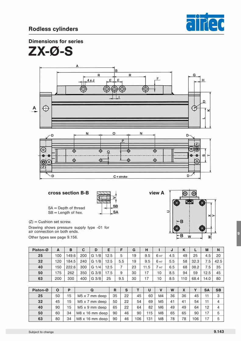
Piston-Ø O P Q R S T U V W X Y SA SB
25 50 15 M5 x 7 mm deep 35 22 45 60 M4 36 36 45 11 3
32 45 15 M5 x 7 mm deep 50 22 54 69 M5 41 41 54 11 4
40 90 15 M5 x 9 mm deep 65 22 64 82 M6 49 49 64 12 4
50 60 34 M8 x 16 mm deep 90 46 90 115 M8 65 65 90 17 5
63 80 34 M8 x 16 mm deep 90 46 106 131 M8 78 78 106 17 5
Piston-Ø A B C D E F G H I J K L M N
25 100 149.6 200 G 1/8 12.5 5 19 9.5 6 H7 4.5 49 25 4.5 20
32 120 184.5 240 G 1/8 12.5 5.5 19 9.5 6 H7 5.5 58 32.3 7.5 42.5
40 150 222.6 300 G 1/4 12.5 7 23 11.5 7 H7 6.5 68 38.2 7.5 35
50 175 262 350 G 3/8 17.5 9 30 17 10 8.5 94 59 12.5 45
63 200 300 400 G 3/8 25 9.5 30 17 10 8.5 110 68.4 14.0 80
Rodless cylinders
Dimensions for series
ZX-Ø-S
(Z) = Cushion set screw.
Drawing shows pressure supply type -01 forair connection on both ends.
Other types see page 9.156.
view Across section B-B
SA = Depth of threadSB = Length of hex.
9.143Subject to change
9

Series ZXLoad, Force and Torque Data
9.140 Subject to change
V in m/s V in ft/s Factor0.2 0.656 10.3 0.984 0.750.4 1.312 0.50.5 1.640 0.4
0.75 2.460 0.271 3.281 0.2
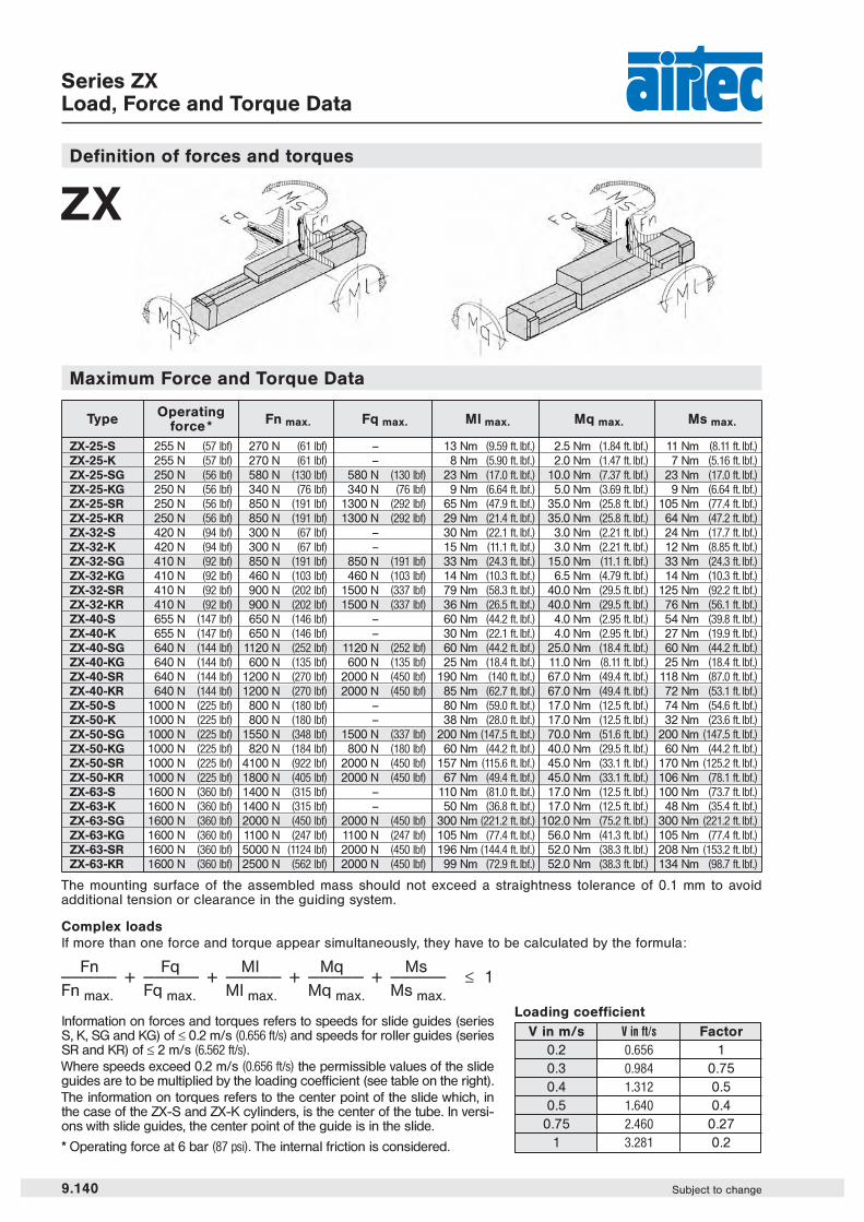
Information on forces and torques refers to speeds for slide guides (seriesS, K, SG and KG) of ≤ 0.2 m/s (0.656 ft/s) and speeds for roller guides (seriesSR and KR) of ≤ 2 m/s (6.562 ft/s).Where speeds exceed 0.2 m/s (0.656 ft/s) the permissible values of the slideguides are to be multiplied by the loading coefficient (see table on the right).The information on torques refers to the center point of the slide which, inthe case of the ZX-S and ZX-K cylinders, is the center of the tube. In versi-ons with slide guides, the center point of the guide is in the slide.
* Operating force at 6 bar (87 psi). The internal friction is considered.
Loading coefficient
Definition of forces and torques
Complex loadsIf more than one force and torque appear simultaneously, they have to be calculated by the formula:
Fn Fq MI Mq Ms————— + ————— + ————— + ————— + ————— ≤ 1Fn max. Fq max. MI max. Mq max. Ms max.
ZX
Type Operating Fn max. Fq max. Ml max. Mq max. Ms max.force *ZX-25-S 255 N (57 lbf) 270 N (61 lbf) – 13 Nm (9.59 ft. lbf.) 2.5 Nm (1.84 ft. lbf.) 11 Nm (8.11 ft. lbf.)
ZX-25-K 255 N (57 lbf) 270 N (61 lbf) – 8 Nm (5.90 ft. lbf.) 2.0 Nm (1.47 ft. lbf.) 7 Nm (5.16 ft. lbf.)
ZX-25-SG 250 N (56 lbf) 580 N (130 lbf) 580 N (130 lbf) 23 Nm (17.0 ft. lbf.) 10.0 Nm (7.37 ft. lbf.) 23 Nm (17.0 ft. lbf.)
ZX-25-KG 250 N (56 lbf) 340 N (76 lbf) 340 N (76 lbf) 9 Nm (6.64 ft. lbf.) 5.0 Nm (3.69 ft. lbf.) 9 Nm (6.64 ft. lbf.)
ZX-25-SR 250 N (56 lbf) 850 N (191 lbf) 1300 N (292 lbf) 65 Nm (47.9 ft. lbf.) 35.0 Nm (25.8 ft. lbf.) 105 Nm (77.4 ft. lbf.)
ZX-25-KR 250 N (56 lbf) 850 N (191 lbf) 1300 N (292 lbf) 29 Nm (21.4 ft. lbf.) 35.0 Nm (25.8 ft. lbf.) 64 Nm (47.2 ft. lbf.)
ZX-32-S 420 N (94 lbf) 300 N (67 lbf) – 30 Nm (22.1 ft. lbf.) 3.0 Nm (2.21 ft. lbf.) 24 Nm (17.7 ft. lbf.)
ZX-32-K 420 N (94 lbf) 300 N (67 lbf) – 15 Nm (11.1 ft. lbf.) 3.0 Nm (2.21 ft. lbf.) 12 Nm (8.85 ft. lbf.)
ZX-32-SG 410 N (92 lbf) 850 N (191 lbf) 850 N (191 lbf) 33 Nm (24.3 ft. lbf.) 15.0 Nm (11.1 ft. lbf.) 33 Nm (24.3 ft. lbf.)
ZX-32-KG 410 N (92 lbf) 460 N (103 lbf) 460 N (103 lbf) 14 Nm (10.3 ft. lbf.) 6.5 Nm (4.79 ft. lbf.) 14 Nm (10.3 ft. lbf.)
ZX-32-SR 410 N (92 lbf) 900 N (202 lbf) 1500 N (337 lbf) 79 Nm (58.3 ft. lbf.) 40.0 Nm (29.5 ft. lbf.) 125 Nm (92.2 ft. lbf.)
ZX-32-KR 410 N (92 lbf) 900 N (202 lbf) 1500 N (337 lbf) 36 Nm (26.5 ft. lbf.) 40.0 Nm (29.5 ft. lbf.) 76 Nm (56.1 ft. lbf.)
ZX-40-S 655 N (147 lbf) 650 N (146 lbf) – 60 Nm (44.2 ft. lbf.) 4.0 Nm (2.95 ft. lbf.) 54 Nm (39.8 ft. lbf.)
ZX-40-K 655 N (147 lbf) 650 N (146 lbf) – 30 Nm (22.1 ft. lbf.) 4.0 Nm (2.95 ft. lbf.) 27 Nm (19.9 ft. lbf.)
ZX-40-SG 640 N (144 lbf) 1120 N (252 lbf) 1120 N (252 lbf) 60 Nm (44.2 ft. lbf.) 25.0 Nm (18.4 ft. lbf.) 60 Nm (44.2 ft. lbf.)
ZX-40-KG 640 N (144 lbf) 600 N (135 lbf) 600 N (135 lbf) 25 Nm (18.4 ft. lbf.) 11.0 Nm (8.11 ft. lbf.) 25 Nm (18.4 ft. lbf.)
ZX-40-SR 640 N (144 lbf) 1200 N (270 lbf) 2000 N (450 lbf) 190 Nm (140 ft. lbf.) 67.0 Nm (49.4 ft. lbf.) 118 Nm (87.0 ft. lbf.)
ZX-40-KR 640 N (144 lbf) 1200 N (270 lbf) 2000 N (450 lbf) 85 Nm (62.7 ft. lbf.) 67.0 Nm (49.4 ft. lbf.) 72 Nm (53.1 ft. lbf.)
ZX-50-S 1000 N (225 lbf) 800 N (180 lbf) – 80 Nm (59.0 ft. lbf.) 17.0 Nm (12.5 ft. lbf.) 74 Nm (54.6 ft. lbf.)
ZX-50-K 1000 N (225 lbf) 800 N (180 lbf) – 38 Nm (28.0 ft. lbf.) 17.0 Nm (12.5 ft. lbf.) 32 Nm (23.6 ft. lbf.)
ZX-50-SG 1000 N (225 lbf) 1550 N (348 lbf) 1500 N (337 lbf) 200 Nm (147.5 ft. lbf.) 70.0 Nm (51.6 ft. lbf.) 200 Nm (147.5 ft. lbf.)
ZX-50-KG 1000 N (225 lbf) 820 N (184 lbf) 800 N (180 lbf) 60 Nm (44.2 ft. lbf.) 40.0 Nm (29.5 ft. lbf.) 60 Nm (44.2 ft. lbf.)
ZX-50-SR 1000 N (225 lbf) 4100 N (922 lbf) 2000 N (450 lbf) 157 Nm (115.6 ft. lbf.) 45.0 Nm (33.1 ft. lbf.) 170 Nm (125.2 ft. lbf.)
ZX-50-KR 1000 N (225 lbf) 1800 N (405 lbf) 2000 N (450 lbf) 67 Nm (49.4 ft. lbf.) 45.0 Nm (33.1 ft. lbf.) 106 Nm (78.1 ft. lbf.)
ZX-63-S 1600 N (360 lbf) 1400 N (315 lbf) – 110 Nm (81.0 ft. lbf.) 17.0 Nm (12.5 ft. lbf.) 100 Nm (73.7 ft. lbf.)
ZX-63-K 1600 N (360 lbf) 1400 N (315 lbf) – 50 Nm (36.8 ft. lbf.) 17.0 Nm (12.5 ft. lbf.) 48 Nm (35.4 ft. lbf.)
ZX-63-SG 1600 N (360 lbf) 2000 N (450 lbf) 2000 N (450 lbf) 300 Nm (221.2 ft. lbf.) 102.0 Nm (75.2 ft. lbf.) 300 Nm (221.2 ft. lbf.)
ZX-63-KG 1600 N (360 lbf) 1100 N (247 lbf) 1100 N (247 lbf) 105 Nm (77.4 ft. lbf.) 56.0 Nm (41.3 ft. lbf.) 105 Nm (77.4 ft. lbf.)
ZX-63-SR 1600 N (360 lbf) 5000 N (1124 lbf) 2000 N (450 lbf) 196 Nm (144.4 ft. lbf.) 52.0 Nm (38.3 ft. lbf.) 208 Nm (153.2 ft. lbf.)
ZX-63-KR 1600 N (360 lbf) 2500 N (562 lbf) 2000 N (450 lbf) 99 Nm (72.9 ft. lbf.) 52.0 Nm (38.3 ft. lbf.) 134 Nm (98.7 ft. lbf.)
Maximum Force and Torque Data
The mounting surface of the assembled mass should not exceed a straightness tolerance of 0.1 mm to avoidadditional tension or clearance in the guiding system.

Series ZXLoad, Force and Torque Data
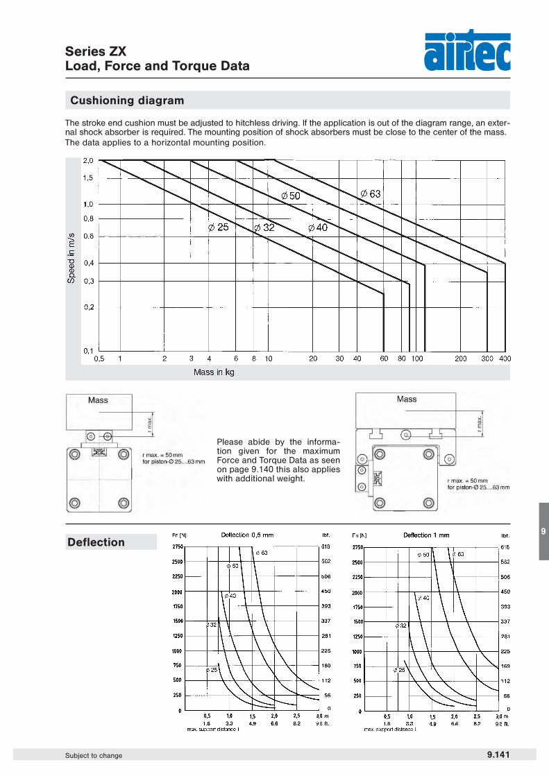
Cushioning diagram
Deflection
9.141Subject to change
9
The stroke end cushion must be adjusted to hitchless driving. If the application is out of the diagram range, an exter-nal shock absorber is required. The mounting position of shock absorbers must be close to the center of the mass.The data applies to a horizontal mounting position.
Please abide by the informa-tion given for the maximumForce and Torque Data as seenon page 9.140 this also applieswith additional weight.
Order numberZX-25-K-… ZX-32-K-… ZX-40-K-… ZX-50-K-… ZX-63-K-…Please complete according
to order code.
Piston-Ø (mm) 25 32 40 50 63
Connection G 1/8 G 1/8 G 1/4 G 3/8 G 3/8
Cushioning length (mm) 24 28 36 45 59
Mass at 0 mm stroke 0.62 kg 0.96 kg 1.65 kg 3.5 kg 5.4 kg(1.367 lbs.) (2.116 lbs.) (3.637 lbs.) (7.716 lbs.) (11.905 lbs.)
additional mass 0.30 kg 0.39 kg 0.52 kg 0.96 kg 1.32 kgper 100 mm (0.661 lb.) (0.860 lb.) (1.168 lbs.) (2.116 lbs.) (2.91 lbs.)
Operating pressure 1 … 8 bar (14.5 … 116 psi)
Temperature range – 10 °C … + 70 °C (+ 14 °F … + 158 °F)
Medium filtered and slightly lubricated or filtered non-lubricated air.If speeds exceed 1 m/s (3.3 ft/s) lubricated air is recommended.
Stroke length arbitrary up to 6000 mm (236 in)
Materials Al (anodized), plasticSeals: NBR, PU
Rodless short cylinders
Technical data for series
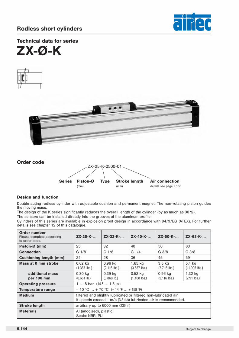
ZX-Ø-K
Design and function
Double acting rodless cylinder with adjustable cushion and permanent magnet. The non-rotating piston guidesthe moving mass.The design of the K series significantly reduces the overall length of the cylinder (by as much as 30 %).The sensors can be installed directly into the grooves of the aluminum profile.Cylinders of this series are available in explosion proof design in accordance with 94/9/EG (ATEX). For furtherdetails see chapter 12 of this catalogue.
Order codeZX-25-K-0500-01
Series Piston-Ø(mm)
Stroke length(mm)
Air connectiondetails see page 9.156
Type
9.144 Subject to change
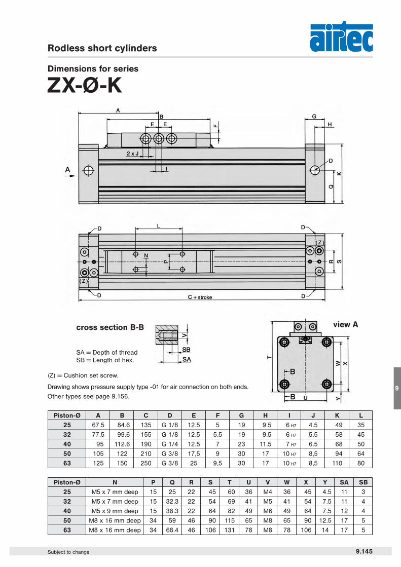
Piston-Ø A B C D E F G H I J K L
25 67.5 84.6 135 G 1/8 12.5 5 19 9.5 6 H7 4.5 49 35
32 77.5 99.6 155 G 1/8 12.5 5.5 19 9.5 6 H7 5.5 58 45
40 95 112.6 190 G 1/4 12.5 7 23 11.5 7 H7 6.5 68 50
50 105 122 210 G 3/8 17,5 9 30 17 10 H7 8,5 94 64
63 125 150 250 G 3/8 25 9,5 30 17 10 H7 8,5 110 80
Piston-Ø N P Q R S T U V W X Y SA SB
25 M5 x 7 mm deep 15 25 22 45 60 36 M4 36 45 4.5 11 3
32 M5 x 7 mm deep 15 32.3 22 54 69 41 M5 41 54 7.5 11 4
40 M5 x 9 mm deep 15 38.3 22 64 82 49 M6 49 64 7.5 12 4
50 M8 x 16 mm deep 34 59 46 90 115 65 M8 65 90 12.5 17 5
63 M8 x 16 mm deep 34 68.4 46 106 131 78 M8 78 106 14 17 5
Rodless short cylinders
Dimensions for series
ZX-Ø-K
(Z) = Cushion set screw.
Drawing shows pressure supply type -01 for air connection on both ends.
Other types see page 9.156.
view Across section B-B
SA = Depth of threadSB = Length of hex.
9.145Subject to change
9

Series ZXLoad, Force and Torque Data
9.140 Subject to change
V in m/s V in ft/s Factor0.2 0.656 10.3 0.984 0.750.4 1.312 0.50.5 1.640 0.4
0.75 2.460 0.271 3.281 0.2
Information on forces and torques refers to speeds for slide guides (seriesS, K, SG and KG) of ≤ 0.2 m/s (0.656 ft/s) and speeds for roller guides (seriesSR and KR) of ≤ 2 m/s (6.562 ft/s).Where speeds exceed 0.2 m/s (0.656 ft/s) the permissible values of the slideguides are to be multiplied by the loading coefficient (see table on the right).The information on torques refers to the center point of the slide which, inthe case of the ZX-S and ZX-K cylinders, is the center of the tube. In versi-ons with slide guides, the center point of the guide is in the slide.
* Operating force at 6 bar (87 psi). The internal friction is considered.
Loading coefficient
Definition of forces and torques
Complex loadsIf more than one force and torque appear simultaneously, they have to be calculated by the formula:
Fn Fq MI Mq Ms————— + ————— + ————— + ————— + ————— ≤ 1Fn max. Fq max. MI max. Mq max. Ms max.
ZX
Type Operating Fn max. Fq max. Ml max. Mq max. Ms max.force *ZX-25-S 255 N (57 lbf) 270 N (61 lbf) – 13 Nm (9.59 ft. lbf.) 2.5 Nm (1.84 ft. lbf.) 11 Nm (8.11 ft. lbf.)
ZX-25-K 255 N (57 lbf) 270 N (61 lbf) – 8 Nm (5.90 ft. lbf.) 2.0 Nm (1.47 ft. lbf.) 7 Nm (5.16 ft. lbf.)
ZX-25-SG 250 N (56 lbf) 580 N (130 lbf) 580 N (130 lbf) 23 Nm (17.0 ft. lbf.) 10.0 Nm (7.37 ft. lbf.) 23 Nm (17.0 ft. lbf.)
ZX-25-KG 250 N (56 lbf) 340 N (76 lbf) 340 N (76 lbf) 9 Nm (6.64 ft. lbf.) 5.0 Nm (3.69 ft. lbf.) 9 Nm (6.64 ft. lbf.)
ZX-25-SR 250 N (56 lbf) 850 N (191 lbf) 1300 N (292 lbf) 65 Nm (47.9 ft. lbf.) 35.0 Nm (25.8 ft. lbf.) 105 Nm (77.4 ft. lbf.)
ZX-25-KR 250 N (56 lbf) 850 N (191 lbf) 1300 N (292 lbf) 29 Nm (21.4 ft. lbf.) 35.0 Nm (25.8 ft. lbf.) 64 Nm (47.2 ft. lbf.)
ZX-32-S 420 N (94 lbf) 300 N (67 lbf) – 30 Nm (22.1 ft. lbf.) 3.0 Nm (2.21 ft. lbf.) 24 Nm (17.7 ft. lbf.)
ZX-32-K 420 N (94 lbf) 300 N (67 lbf) – 15 Nm (11.1 ft. lbf.) 3.0 Nm (2.21 ft. lbf.) 12 Nm (8.85 ft. lbf.)
ZX-32-SG 410 N (92 lbf) 850 N (191 lbf) 850 N (191 lbf) 33 Nm (24.3 ft. lbf.) 15.0 Nm (11.1 ft. lbf.) 33 Nm (24.3 ft. lbf.)
ZX-32-KG 410 N (92 lbf) 460 N (103 lbf) 460 N (103 lbf) 14 Nm (10.3 ft. lbf.) 6.5 Nm (4.79 ft. lbf.) 14 Nm (10.3 ft. lbf.)
ZX-32-SR 410 N (92 lbf) 900 N (202 lbf) 1500 N (337 lbf) 79 Nm (58.3 ft. lbf.) 40.0 Nm (29.5 ft. lbf.) 125 Nm (92.2 ft. lbf.)
ZX-32-KR 410 N (92 lbf) 900 N (202 lbf) 1500 N (337 lbf) 36 Nm (26.5 ft. lbf.) 40.0 Nm (29.5 ft. lbf.) 76 Nm (56.1 ft. lbf.)
ZX-40-S 655 N (147 lbf) 650 N (146 lbf) – 60 Nm (44.2 ft. lbf.) 4.0 Nm (2.95 ft. lbf.) 54 Nm (39.8 ft. lbf.)
ZX-40-K 655 N (147 lbf) 650 N (146 lbf) – 30 Nm (22.1 ft. lbf.) 4.0 Nm (2.95 ft. lbf.) 27 Nm (19.9 ft. lbf.)
ZX-40-SG 640 N (144 lbf) 1120 N (252 lbf) 1120 N (252 lbf) 60 Nm (44.2 ft. lbf.) 25.0 Nm (18.4 ft. lbf.) 60 Nm (44.2 ft. lbf.)
ZX-40-KG 640 N (144 lbf) 600 N (135 lbf) 600 N (135 lbf) 25 Nm (18.4 ft. lbf.) 11.0 Nm (8.11 ft. lbf.) 25 Nm (18.4 ft. lbf.)
ZX-40-SR 640 N (144 lbf) 1200 N (270 lbf) 2000 N (450 lbf) 190 Nm (140 ft. lbf.) 67.0 Nm (49.4 ft. lbf.) 118 Nm (87.0 ft. lbf.)
ZX-40-KR 640 N (144 lbf) 1200 N (270 lbf) 2000 N (450 lbf) 85 Nm (62.7 ft. lbf.) 67.0 Nm (49.4 ft. lbf.) 72 Nm (53.1 ft. lbf.)
ZX-50-S 1000 N (225 lbf) 800 N (180 lbf) – 80 Nm (59.0 ft. lbf.) 17.0 Nm (12.5 ft. lbf.) 74 Nm (54.6 ft. lbf.)
ZX-50-K 1000 N (225 lbf) 800 N (180 lbf) – 38 Nm (28.0 ft. lbf.) 17.0 Nm (12.5 ft. lbf.) 32 Nm (23.6 ft. lbf.)
ZX-50-SG 1000 N (225 lbf) 1550 N (348 lbf) 1500 N (337 lbf) 200 Nm (147.5 ft. lbf.) 70.0 Nm (51.6 ft. lbf.) 200 Nm (147.5 ft. lbf.)
ZX-50-KG 1000 N (225 lbf) 820 N (184 lbf) 800 N (180 lbf) 60 Nm (44.2 ft. lbf.) 40.0 Nm (29.5 ft. lbf.) 60 Nm (44.2 ft. lbf.)
ZX-50-SR 1000 N (225 lbf) 4100 N (922 lbf) 2000 N (450 lbf) 157 Nm (115.6 ft. lbf.) 45.0 Nm (33.1 ft. lbf.) 170 Nm (125.2 ft. lbf.)
ZX-50-KR 1000 N (225 lbf) 1800 N (405 lbf) 2000 N (450 lbf) 67 Nm (49.4 ft. lbf.) 45.0 Nm (33.1 ft. lbf.) 106 Nm (78.1 ft. lbf.)
ZX-63-S 1600 N (360 lbf) 1400 N (315 lbf) – 110 Nm (81.0 ft. lbf.) 17.0 Nm (12.5 ft. lbf.) 100 Nm (73.7 ft. lbf.)
ZX-63-K 1600 N (360 lbf) 1400 N (315 lbf) – 50 Nm (36.8 ft. lbf.) 17.0 Nm (12.5 ft. lbf.) 48 Nm (35.4 ft. lbf.)
ZX-63-SG 1600 N (360 lbf) 2000 N (450 lbf) 2000 N (450 lbf) 300 Nm (221.2 ft. lbf.) 102.0 Nm (75.2 ft. lbf.) 300 Nm (221.2 ft. lbf.)
ZX-63-KG 1600 N (360 lbf) 1100 N (247 lbf) 1100 N (247 lbf) 105 Nm (77.4 ft. lbf.) 56.0 Nm (41.3 ft. lbf.) 105 Nm (77.4 ft. lbf.)
ZX-63-SR 1600 N (360 lbf) 5000 N (1124 lbf) 2000 N (450 lbf) 196 Nm (144.4 ft. lbf.) 52.0 Nm (38.3 ft. lbf.) 208 Nm (153.2 ft. lbf.)
ZX-63-KR 1600 N (360 lbf) 2500 N (562 lbf) 2000 N (450 lbf) 99 Nm (72.9 ft. lbf.) 52.0 Nm (38.3 ft. lbf.) 134 Nm (98.7 ft. lbf.)
Maximum Force and Torque Data
The mounting surface of the assembled mass should not exceed a straightness tolerance of 0.1 mm to avoidadditional tension or clearance in the guiding system.

Series ZXLoad, Force and Torque Data
Cushioning diagram
Deflection
9.141Subject to change
9
The stroke end cushion must be adjusted to hitchless driving. If the application is out of the diagram range, an exter-nal shock absorber is required. The mounting position of shock absorbers must be close to the center of the mass.The data applies to a horizontal mounting position.
Please abide by the informa-tion given for the maximumForce and Torque Data as seenon page 9.140 this also applieswith additional weight.

Rodless cylinderswith slide guide
Technical data for series
ZX-Ø-SG
Order codeZX-25-SG-0500-01
Series Piston-Ø(mm)
Stroke length(mm)
Air connectiondetails see page 9.156
Type
9.146 Subject to change
Design and function
Double acting rodless cylinder with adjustable cushion and permanent magnet. Series SG incorporates an adju-stable guide system for medium loads.The sensors can be installed directly into the grooves of the aluminum profile.Cylinders of this series are available in explosion proof design in accordance with 94/9/EG (ATEX). For furtherdetails see chapter 12 of this catalogue.
Order numberZX-25-SG-… ZX-32-SG-… ZX-40-SG-… ZX-50-SG-… ZX-63-SG-…Please complete according
to order code.
Piston-Ø (mm) 25 32 40 50 63
Connection G 1/8 G 1/8 G 1/4 G 3/8 G 3/8
Cushioning length (mm) 24 28 36 45 59
Mass at 0 mm stroke 1.31 kg 2.09 kg 3.58 kg 7.28 kg 11.02 kg(2.888 lbs.) (4.608 lbs.) (7.892 lbs.) (16.049 lbs.) (24.294 lbs.)
additional mass 0.30 kg 0.39 kg 0.52 kg 0.96 kg 1.32 kgper 100 mm (0.661 lb.) (0.860 lb.) (1.168 lbs.) (2.116 lbs.) (2.91 lbs.)
Operating pressure 1 … 8 bar (14.5 … 116 psi)
Temperature range – 10 °C … + 70 °C (+ 14 °F … + 158 °F)
Medium filtered and slightly lubricated or filtered non-lubricated air.If speeds exceed 1 m/s (3.3 ft/s) lubricated air is recommended.
Stroke length arbitrary up to 6000 mm max. 5950 mm max. 5910 mm max. 5860 mm(arbitrary up to 236 in) (max. 234 in) (max. 232 in) (max. 230 in)
Materials Al (anodized), plasticSeals: NBR, PU
Rodless cylinderswith slide guide
Dimensions for series
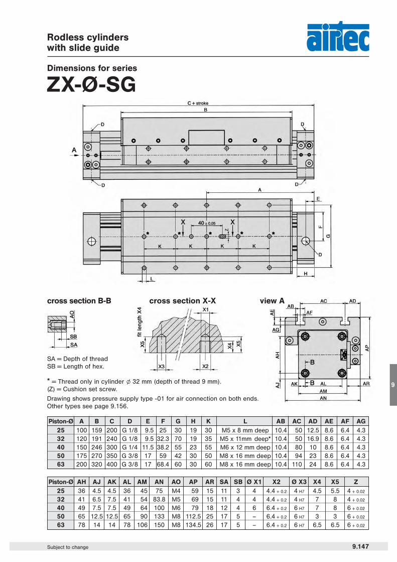
ZX-Ø-SG
* = Thread only in cylinder l 32 mm (depth of thread 9 mm).(Z) = Cushion set screw.
Drawing shows pressure supply type -01 for air connection on both ends.Other types see page 9.156.
9.147Subject to change
9
Piston-Ø AH AJ AK AL AM AN AO AP AR SA SB Ø X1 X2 Ø X3 X4 X5 Z25 36 4.5 4.5 36 45 75 M4 59 15 11 3 4 4.4 + 0.2 4 H7 4.5 5.5 4 + 0.02
32 41 6.5 7.5 41 54 83.8 M5 69 15 11 4 4 4.4 + 0.2 4 H7 7 8 4 + 0.02
40 49 7.5 7.5 49 64 100 M6 79 18 12 4 6 6.4 + 0.2 6 H7 7 8 6 + 0.02
50 65 12.5 12.5 65 90 133 M8 112.5 25 17 5 – 6.4 + 0.2 6 H7 3 3 6 + 0.02
63 78 14 14 78 106 150 M8 134.5 26 17 5 – 6.4 + 0.2 6 H7 6.5 6.5 6 + 0.02
Piston-Ø A B C D E F G H K L AB AC AD AE AF AG25 100 159 200 G 1/8 9.5 25 30 19 30 M5 x 8 mm deep 10.4 50 12.5 8.6 6.4 4.332 120 191 240 G 1/8 9.5 32.3 70 19 35 M5 x 11mm deep* 10.4 50 16.9 8.6 6.4 4.340 150 246 300 G 1/4 11.5 38.2 55 23 55 M6 x 12 mm deep 10.4 80 10 8.6 6.4 4.350 175 270 350 G 3/8 17 59 42 30 50 M8 x 16 mm deep 10.4 94 23 8.6 6.4 4.363 200 320 400 G 3/8 17 68.4 60 30 60 M8 x 16 mm deep 10.4 110 24 8.6 6.4 4.3
view Across section B-B
SA = Depth of threadSB = Length of hex.
cross section X-X

Series ZXLoad, Force and Torque Data
9.140 Subject to change
V in m/s V in ft/s Factor0.2 0.656 10.3 0.984 0.750.4 1.312 0.50.5 1.640 0.4
0.75 2.460 0.271 3.281 0.2
Information on forces and torques refers to speeds for slide guides (seriesS, K, SG and KG) of ≤ 0.2 m/s (0.656 ft/s) and speeds for roller guides (seriesSR and KR) of ≤ 2 m/s (6.562 ft/s).Where speeds exceed 0.2 m/s (0.656 ft/s) the permissible values of the slideguides are to be multiplied by the loading coefficient (see table on the right).The information on torques refers to the center point of the slide which, inthe case of the ZX-S and ZX-K cylinders, is the center of the tube. In versi-ons with slide guides, the center point of the guide is in the slide.
* Operating force at 6 bar (87 psi). The internal friction is considered.
Loading coefficient
Definition of forces and torques
Complex loadsIf more than one force and torque appear simultaneously, they have to be calculated by the formula:
Fn Fq MI Mq Ms————— + ————— + ————— + ————— + ————— ≤ 1Fn max. Fq max. MI max. Mq max. Ms max.
ZX
Type Operating Fn max. Fq max. Ml max. Mq max. Ms max.force *ZX-25-S 255 N (57 lbf) 270 N (61 lbf) – 13 Nm (9.59 ft. lbf.) 2.5 Nm (1.84 ft. lbf.) 11 Nm (8.11 ft. lbf.)
ZX-25-K 255 N (57 lbf) 270 N (61 lbf) – 8 Nm (5.90 ft. lbf.) 2.0 Nm (1.47 ft. lbf.) 7 Nm (5.16 ft. lbf.)
ZX-25-SG 250 N (56 lbf) 580 N (130 lbf) 580 N (130 lbf) 23 Nm (17.0 ft. lbf.) 10.0 Nm (7.37 ft. lbf.) 23 Nm (17.0 ft. lbf.)
ZX-25-KG 250 N (56 lbf) 340 N (76 lbf) 340 N (76 lbf) 9 Nm (6.64 ft. lbf.) 5.0 Nm (3.69 ft. lbf.) 9 Nm (6.64 ft. lbf.)
ZX-25-SR 250 N (56 lbf) 850 N (191 lbf) 1300 N (292 lbf) 65 Nm (47.9 ft. lbf.) 35.0 Nm (25.8 ft. lbf.) 105 Nm (77.4 ft. lbf.)
ZX-25-KR 250 N (56 lbf) 850 N (191 lbf) 1300 N (292 lbf) 29 Nm (21.4 ft. lbf.) 35.0 Nm (25.8 ft. lbf.) 64 Nm (47.2 ft. lbf.)
ZX-32-S 420 N (94 lbf) 300 N (67 lbf) – 30 Nm (22.1 ft. lbf.) 3.0 Nm (2.21 ft. lbf.) 24 Nm (17.7 ft. lbf.)
ZX-32-K 420 N (94 lbf) 300 N (67 lbf) – 15 Nm (11.1 ft. lbf.) 3.0 Nm (2.21 ft. lbf.) 12 Nm (8.85 ft. lbf.)
ZX-32-SG 410 N (92 lbf) 850 N (191 lbf) 850 N (191 lbf) 33 Nm (24.3 ft. lbf.) 15.0 Nm (11.1 ft. lbf.) 33 Nm (24.3 ft. lbf.)
ZX-32-KG 410 N (92 lbf) 460 N (103 lbf) 460 N (103 lbf) 14 Nm (10.3 ft. lbf.) 6.5 Nm (4.79 ft. lbf.) 14 Nm (10.3 ft. lbf.)
ZX-32-SR 410 N (92 lbf) 900 N (202 lbf) 1500 N (337 lbf) 79 Nm (58.3 ft. lbf.) 40.0 Nm (29.5 ft. lbf.) 125 Nm (92.2 ft. lbf.)
ZX-32-KR 410 N (92 lbf) 900 N (202 lbf) 1500 N (337 lbf) 36 Nm (26.5 ft. lbf.) 40.0 Nm (29.5 ft. lbf.) 76 Nm (56.1 ft. lbf.)
ZX-40-S 655 N (147 lbf) 650 N (146 lbf) – 60 Nm (44.2 ft. lbf.) 4.0 Nm (2.95 ft. lbf.) 54 Nm (39.8 ft. lbf.)
ZX-40-K 655 N (147 lbf) 650 N (146 lbf) – 30 Nm (22.1 ft. lbf.) 4.0 Nm (2.95 ft. lbf.) 27 Nm (19.9 ft. lbf.)
ZX-40-SG 640 N (144 lbf) 1120 N (252 lbf) 1120 N (252 lbf) 60 Nm (44.2 ft. lbf.) 25.0 Nm (18.4 ft. lbf.) 60 Nm (44.2 ft. lbf.)
ZX-40-KG 640 N (144 lbf) 600 N (135 lbf) 600 N (135 lbf) 25 Nm (18.4 ft. lbf.) 11.0 Nm (8.11 ft. lbf.) 25 Nm (18.4 ft. lbf.)
ZX-40-SR 640 N (144 lbf) 1200 N (270 lbf) 2000 N (450 lbf) 190 Nm (140 ft. lbf.) 67.0 Nm (49.4 ft. lbf.) 118 Nm (87.0 ft. lbf.)
ZX-40-KR 640 N (144 lbf) 1200 N (270 lbf) 2000 N (450 lbf) 85 Nm (62.7 ft. lbf.) 67.0 Nm (49.4 ft. lbf.) 72 Nm (53.1 ft. lbf.)
ZX-50-S 1000 N (225 lbf) 800 N (180 lbf) – 80 Nm (59.0 ft. lbf.) 17.0 Nm (12.5 ft. lbf.) 74 Nm (54.6 ft. lbf.)
ZX-50-K 1000 N (225 lbf) 800 N (180 lbf) – 38 Nm (28.0 ft. lbf.) 17.0 Nm (12.5 ft. lbf.) 32 Nm (23.6 ft. lbf.)
ZX-50-SG 1000 N (225 lbf) 1550 N (348 lbf) 1500 N (337 lbf) 200 Nm (147.5 ft. lbf.) 70.0 Nm (51.6 ft. lbf.) 200 Nm (147.5 ft. lbf.)
ZX-50-KG 1000 N (225 lbf) 820 N (184 lbf) 800 N (180 lbf) 60 Nm (44.2 ft. lbf.) 40.0 Nm (29.5 ft. lbf.) 60 Nm (44.2 ft. lbf.)
ZX-50-SR 1000 N (225 lbf) 4100 N (922 lbf) 2000 N (450 lbf) 157 Nm (115.6 ft. lbf.) 45.0 Nm (33.1 ft. lbf.) 170 Nm (125.2 ft. lbf.)
ZX-50-KR 1000 N (225 lbf) 1800 N (405 lbf) 2000 N (450 lbf) 67 Nm (49.4 ft. lbf.) 45.0 Nm (33.1 ft. lbf.) 106 Nm (78.1 ft. lbf.)
ZX-63-S 1600 N (360 lbf) 1400 N (315 lbf) – 110 Nm (81.0 ft. lbf.) 17.0 Nm (12.5 ft. lbf.) 100 Nm (73.7 ft. lbf.)
ZX-63-K 1600 N (360 lbf) 1400 N (315 lbf) – 50 Nm (36.8 ft. lbf.) 17.0 Nm (12.5 ft. lbf.) 48 Nm (35.4 ft. lbf.)
ZX-63-SG 1600 N (360 lbf) 2000 N (450 lbf) 2000 N (450 lbf) 300 Nm (221.2 ft. lbf.) 102.0 Nm (75.2 ft. lbf.) 300 Nm (221.2 ft. lbf.)
ZX-63-KG 1600 N (360 lbf) 1100 N (247 lbf) 1100 N (247 lbf) 105 Nm (77.4 ft. lbf.) 56.0 Nm (41.3 ft. lbf.) 105 Nm (77.4 ft. lbf.)
ZX-63-SR 1600 N (360 lbf) 5000 N (1124 lbf) 2000 N (450 lbf) 196 Nm (144.4 ft. lbf.) 52.0 Nm (38.3 ft. lbf.) 208 Nm (153.2 ft. lbf.)
ZX-63-KR 1600 N (360 lbf) 2500 N (562 lbf) 2000 N (450 lbf) 99 Nm (72.9 ft. lbf.) 52.0 Nm (38.3 ft. lbf.) 134 Nm (98.7 ft. lbf.)
Maximum Force and Torque Data
The mounting surface of the assembled mass should not exceed a straightness tolerance of 0.1 mm to avoidadditional tension or clearance in the guiding system.

Series ZXLoad, Force and Torque Data
Cushioning diagram
Deflection
9.141Subject to change
9
The stroke end cushion must be adjusted to hitchless driving. If the application is out of the diagram range, an exter-nal shock absorber is required. The mounting position of shock absorbers must be close to the center of the mass.The data applies to a horizontal mounting position.
Please abide by the informa-tion given for the maximumForce and Torque Data as seenon page 9.140 this also applieswith additional weight.

Rodless short cylinderswith slide guide
Technical data for series
ZX-Ø-KG
Order codeZX-25-KG-0500-01
Series Piston-Ø(mm)
Stroke length(mm)
Air connectiondetails see page 9.156
Type
9.148 Subject to change
Design and function
Double acting rodless cylinder with adjustable cushion and permanent magnet. Series KG incorporates an adju-stable guide system for medium loads.The design of the KG series cylinder significantly reduces the overall length of the cylinder (by as much as 30 %).The sensors can be installed directly into the grooves of the aluminum profile.Cylinders of this series are available in explosion proof design in accordance with 94/9/EG (ATEX). For furtherdetails see chapter 12 of this catalogue.
Order numberZX-25-KG-… ZX-32-KG-… ZX-40-KG-… ZX-50-KG-… ZX-63-KG-…Please complete according
to order code.
Piston-Ø (mm) 25 32 40 50 63
Connection G 1/8 G 1/8 G 1/4 G 3/8 G 3/8
Cushioning length (mm) 24 28 36 45 59
Mass at 0 mm stroke 0.88 kg 1.35 kg 2.30 kg 4.63 kg 7.1 kg(1.940 lbs.) (2.976 lbs.) (5.070 lbs.) (10.207 lbs.) (15.652 lbs.)
additional mass 0.30 kg 0.39 kg 0.52 kg 0.96 kg 1.32 kgper 100 mm (0.661 lb.) (0.860 lb.) (1.168 lbs.) (2.116 lbs.) (2.91 lbs.)
Operating pressure 1 … 8 bar (14.5 … 116 psi)
Temperature range – 10 °C … + 70 °C (+ 14 °F … + 158 °F)
Medium filtered and slightly lubricated or filtered non-lubricated air.If speeds exceed 1 m/s (3.3 ft/s) lubricated air is recommended.
Stroke length arbitrary up to 6000 mm (236 in)
Materials Al (anodized), plasticSeals: NBR, PU
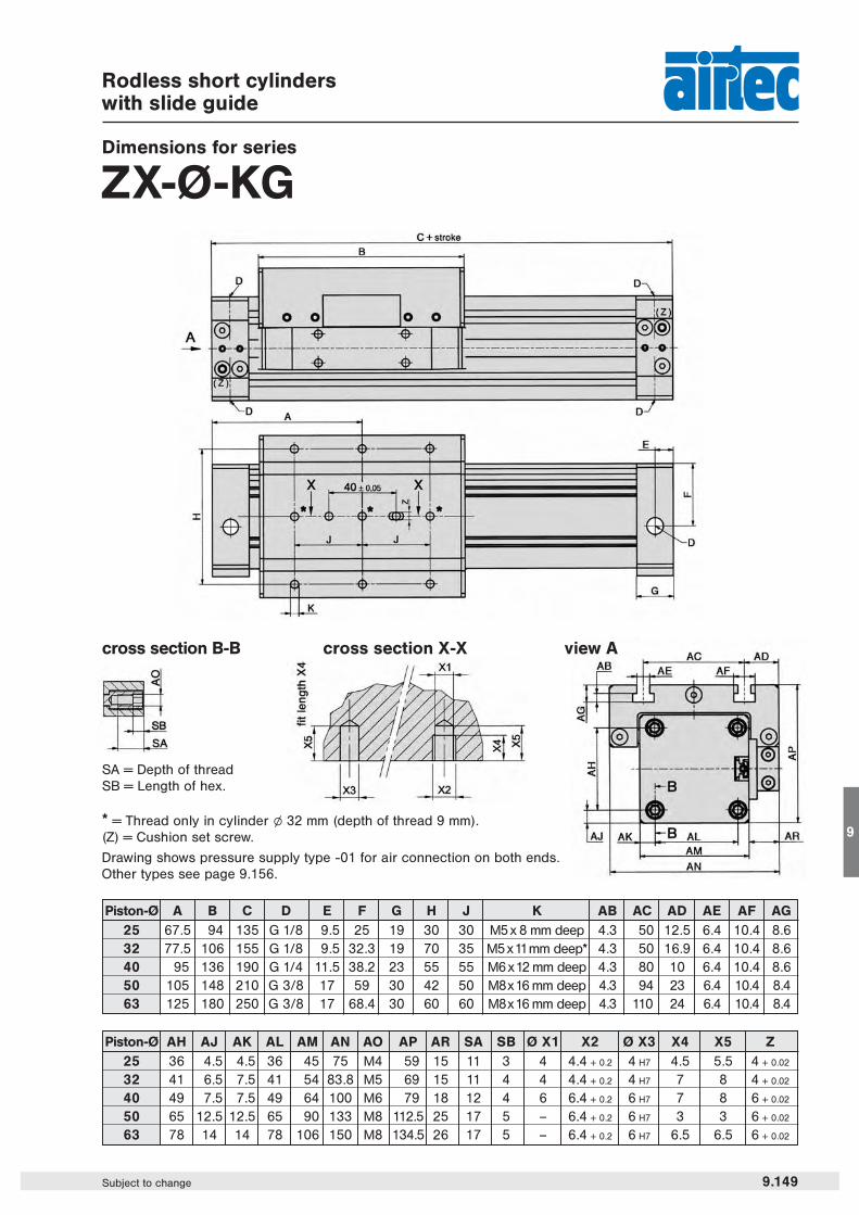
Rodless short cylinderswith slide guide
Dimensions for series
ZX-Ø-KG
* = Thread only in cylinder l 32 mm (depth of thread 9 mm).(Z) = Cushion set screw.
Drawing shows pressure supply type -01 for air connection on both ends.Other types see page 9.156.
9.149Subject to change
9
view Across section B-B
SA = Depth of threadSB = Length of hex.
cross section X-X
Piston-Ø A B C D E F G H J K AB AC AD AE AF AG25 67.5 94 135 G 1/8 9.5 25 19 30 30 M5 x 8 mm deep 4.3 50 12.5 6.4 10.4 8.632 77.5 106 155 G 1/8 9.5 32.3 19 70 35 M5 x11mm deep* 4.3 50 16.9 6.4 10.4 8.640 95 136 190 G 1/4 11.5 38.2 23 55 55 M6 x12 mm deep 4.3 80 10 6.4 10.4 8.650 105 148 210 G 3/8 17 59 30 42 50 M8x16 mm deep 4.3 94 23 6.4 10.4 8.463 125 180 250 G 3/8 17 68.4 30 60 60 M8x16 mm deep 4.3 110 24 6.4 10.4 8.4
Piston-Ø AH AJ AK AL AM AN AO AP AR SA SB Ø X1 X2 Ø X3 X4 X5 Z25 36 4.5 4.5 36 45 75 M4 59 15 11 3 4 4.4 + 0.2 4 H7 4.5 5.5 4 + 0.02
32 41 6.5 7.5 41 54 83.8 M5 69 15 11 4 4 4.4 + 0.2 4 H7 7 8 4 + 0.02
40 49 7.5 7.5 49 64 100 M6 79 18 12 4 6 6.4 + 0.2 6 H7 7 8 6 + 0.02
50 65 12.5 12.5 65 90 133 M8 112.5 25 17 5 – 6.4 + 0.2 6 H7 3 3 6 + 0.02
63 78 14 14 78 106 150 M8 134.5 26 17 5 – 6.4 + 0.2 6 H7 6.5 6.5 6 + 0.02

Series ZXLoad, Force and Torque Data
9.140 Subject to change
V in m/s V in ft/s Factor0.2 0.656 10.3 0.984 0.750.4 1.312 0.50.5 1.640 0.4
0.75 2.460 0.271 3.281 0.2
Information on forces and torques refers to speeds for slide guides (seriesS, K, SG and KG) of ≤ 0.2 m/s (0.656 ft/s) and speeds for roller guides (seriesSR and KR) of ≤ 2 m/s (6.562 ft/s).Where speeds exceed 0.2 m/s (0.656 ft/s) the permissible values of the slideguides are to be multiplied by the loading coefficient (see table on the right).The information on torques refers to the center point of the slide which, inthe case of the ZX-S and ZX-K cylinders, is the center of the tube. In versi-ons with slide guides, the center point of the guide is in the slide.
* Operating force at 6 bar (87 psi). The internal friction is considered.
Loading coefficient
Definition of forces and torques
Complex loadsIf more than one force and torque appear simultaneously, they have to be calculated by the formula:
Fn Fq MI Mq Ms————— + ————— + ————— + ————— + ————— ≤ 1Fn max. Fq max. MI max. Mq max. Ms max.
ZX
Type Operating Fn max. Fq max. Ml max. Mq max. Ms max.force *ZX-25-S 255 N (57 lbf) 270 N (61 lbf) – 13 Nm (9.59 ft. lbf.) 2.5 Nm (1.84 ft. lbf.) 11 Nm (8.11 ft. lbf.)
ZX-25-K 255 N (57 lbf) 270 N (61 lbf) – 8 Nm (5.90 ft. lbf.) 2.0 Nm (1.47 ft. lbf.) 7 Nm (5.16 ft. lbf.)
ZX-25-SG 250 N (56 lbf) 580 N (130 lbf) 580 N (130 lbf) 23 Nm (17.0 ft. lbf.) 10.0 Nm (7.37 ft. lbf.) 23 Nm (17.0 ft. lbf.)
ZX-25-KG 250 N (56 lbf) 340 N (76 lbf) 340 N (76 lbf) 9 Nm (6.64 ft. lbf.) 5.0 Nm (3.69 ft. lbf.) 9 Nm (6.64 ft. lbf.)
ZX-25-SR 250 N (56 lbf) 850 N (191 lbf) 1300 N (292 lbf) 65 Nm (47.9 ft. lbf.) 35.0 Nm (25.8 ft. lbf.) 105 Nm (77.4 ft. lbf.)
ZX-25-KR 250 N (56 lbf) 850 N (191 lbf) 1300 N (292 lbf) 29 Nm (21.4 ft. lbf.) 35.0 Nm (25.8 ft. lbf.) 64 Nm (47.2 ft. lbf.)
ZX-32-S 420 N (94 lbf) 300 N (67 lbf) – 30 Nm (22.1 ft. lbf.) 3.0 Nm (2.21 ft. lbf.) 24 Nm (17.7 ft. lbf.)
ZX-32-K 420 N (94 lbf) 300 N (67 lbf) – 15 Nm (11.1 ft. lbf.) 3.0 Nm (2.21 ft. lbf.) 12 Nm (8.85 ft. lbf.)
ZX-32-SG 410 N (92 lbf) 850 N (191 lbf) 850 N (191 lbf) 33 Nm (24.3 ft. lbf.) 15.0 Nm (11.1 ft. lbf.) 33 Nm (24.3 ft. lbf.)
ZX-32-KG 410 N (92 lbf) 460 N (103 lbf) 460 N (103 lbf) 14 Nm (10.3 ft. lbf.) 6.5 Nm (4.79 ft. lbf.) 14 Nm (10.3 ft. lbf.)
ZX-32-SR 410 N (92 lbf) 900 N (202 lbf) 1500 N (337 lbf) 79 Nm (58.3 ft. lbf.) 40.0 Nm (29.5 ft. lbf.) 125 Nm (92.2 ft. lbf.)
ZX-32-KR 410 N (92 lbf) 900 N (202 lbf) 1500 N (337 lbf) 36 Nm (26.5 ft. lbf.) 40.0 Nm (29.5 ft. lbf.) 76 Nm (56.1 ft. lbf.)
ZX-40-S 655 N (147 lbf) 650 N (146 lbf) – 60 Nm (44.2 ft. lbf.) 4.0 Nm (2.95 ft. lbf.) 54 Nm (39.8 ft. lbf.)
ZX-40-K 655 N (147 lbf) 650 N (146 lbf) – 30 Nm (22.1 ft. lbf.) 4.0 Nm (2.95 ft. lbf.) 27 Nm (19.9 ft. lbf.)
ZX-40-SG 640 N (144 lbf) 1120 N (252 lbf) 1120 N (252 lbf) 60 Nm (44.2 ft. lbf.) 25.0 Nm (18.4 ft. lbf.) 60 Nm (44.2 ft. lbf.)
ZX-40-KG 640 N (144 lbf) 600 N (135 lbf) 600 N (135 lbf) 25 Nm (18.4 ft. lbf.) 11.0 Nm (8.11 ft. lbf.) 25 Nm (18.4 ft. lbf.)
ZX-40-SR 640 N (144 lbf) 1200 N (270 lbf) 2000 N (450 lbf) 190 Nm (140 ft. lbf.) 67.0 Nm (49.4 ft. lbf.) 118 Nm (87.0 ft. lbf.)
ZX-40-KR 640 N (144 lbf) 1200 N (270 lbf) 2000 N (450 lbf) 85 Nm (62.7 ft. lbf.) 67.0 Nm (49.4 ft. lbf.) 72 Nm (53.1 ft. lbf.)
ZX-50-S 1000 N (225 lbf) 800 N (180 lbf) – 80 Nm (59.0 ft. lbf.) 17.0 Nm (12.5 ft. lbf.) 74 Nm (54.6 ft. lbf.)
ZX-50-K 1000 N (225 lbf) 800 N (180 lbf) – 38 Nm (28.0 ft. lbf.) 17.0 Nm (12.5 ft. lbf.) 32 Nm (23.6 ft. lbf.)
ZX-50-SG 1000 N (225 lbf) 1550 N (348 lbf) 1500 N (337 lbf) 200 Nm (147.5 ft. lbf.) 70.0 Nm (51.6 ft. lbf.) 200 Nm (147.5 ft. lbf.)
ZX-50-KG 1000 N (225 lbf) 820 N (184 lbf) 800 N (180 lbf) 60 Nm (44.2 ft. lbf.) 40.0 Nm (29.5 ft. lbf.) 60 Nm (44.2 ft. lbf.)
ZX-50-SR 1000 N (225 lbf) 4100 N (922 lbf) 2000 N (450 lbf) 157 Nm (115.6 ft. lbf.) 45.0 Nm (33.1 ft. lbf.) 170 Nm (125.2 ft. lbf.)
ZX-50-KR 1000 N (225 lbf) 1800 N (405 lbf) 2000 N (450 lbf) 67 Nm (49.4 ft. lbf.) 45.0 Nm (33.1 ft. lbf.) 106 Nm (78.1 ft. lbf.)
ZX-63-S 1600 N (360 lbf) 1400 N (315 lbf) – 110 Nm (81.0 ft. lbf.) 17.0 Nm (12.5 ft. lbf.) 100 Nm (73.7 ft. lbf.)
ZX-63-K 1600 N (360 lbf) 1400 N (315 lbf) – 50 Nm (36.8 ft. lbf.) 17.0 Nm (12.5 ft. lbf.) 48 Nm (35.4 ft. lbf.)
ZX-63-SG 1600 N (360 lbf) 2000 N (450 lbf) 2000 N (450 lbf) 300 Nm (221.2 ft. lbf.) 102.0 Nm (75.2 ft. lbf.) 300 Nm (221.2 ft. lbf.)
ZX-63-KG 1600 N (360 lbf) 1100 N (247 lbf) 1100 N (247 lbf) 105 Nm (77.4 ft. lbf.) 56.0 Nm (41.3 ft. lbf.) 105 Nm (77.4 ft. lbf.)
ZX-63-SR 1600 N (360 lbf) 5000 N (1124 lbf) 2000 N (450 lbf) 196 Nm (144.4 ft. lbf.) 52.0 Nm (38.3 ft. lbf.) 208 Nm (153.2 ft. lbf.)
ZX-63-KR 1600 N (360 lbf) 2500 N (562 lbf) 2000 N (450 lbf) 99 Nm (72.9 ft. lbf.) 52.0 Nm (38.3 ft. lbf.) 134 Nm (98.7 ft. lbf.)
Maximum Force and Torque Data
The mounting surface of the assembled mass should not exceed a straightness tolerance of 0.1 mm to avoidadditional tension or clearance in the guiding system.

Series ZXLoad, Force and Torque Data
Cushioning diagram
Deflection
9.141Subject to change
9
The stroke end cushion must be adjusted to hitchless driving. If the application is out of the diagram range, an exter-nal shock absorber is required. The mounting position of shock absorbers must be close to the center of the mass.The data applies to a horizontal mounting position.
Please abide by the informa-tion given for the maximumForce and Torque Data as seenon page 9.140 this also applieswith additional weight.
Order numberZX-25-SR-… ZX-32-SR-… ZX-40-SR-… ZX-50-SR-… ZX-63-SR-…Please complete according
to order code.
Piston-Ø (mm) 25 32 40 50 63
Connection G 1/8 G 1/8 G 1/4 G 3/8 G 3/8
Cushioning length (mm) 24 28 36 45 59
Mass at 0 mm stroke 1.97 kg 2.96 kg 5.89 kg 9.10 kg 13.17 kg(4.343 lbs.) (6.525 lbs.) (12.985 lbs.) (20.062 lbs.) (29.035 lbs.)
additional mass per 100 mm 0.42 kg 0.48 kg 0.74 kg 1.08 kg 1.42 kg(0.926 lb.) (1.058 lbs.) (1.631 lbs.) (2.381 lbs.) (3.130 lbs.)
Operating pressure 1.5 … 8 bar 1 … 8 bar(21.75 …116 psi) (14.5 … 116 psi)
Temperature range – 10 °C … + 70 °C (+ 14 °F … + 158 °F)
Medium filtered and slightly lubricated or filtered non-lubricated air.If speeds exceed 1 m/s (3.3 ft/s) lubricated air is recommended.
Stroke length arbitrary up to 6000 mm max. 5950 mm max. 5910 mm max. 5860 mm(236 in) (234 in) (233 in) (231 in)
Materials Al (anodized), plastic, hardened steelSeals: NBR, PU
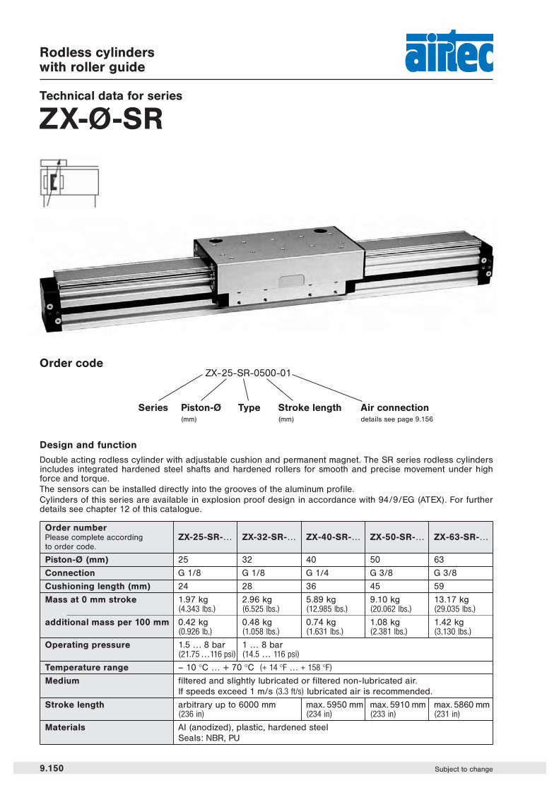
Rodless cylinderswith roller guide
Technical data for series
ZX-Ø-SR
Design and function
Double acting rodless cylinder with adjustable cushion and permanent magnet. The SR series rodless cylindersincludes integrated hardened steel shafts and hardened rollers for smooth and precise movement under highforce and torque.The sensors can be installed directly into the grooves of the aluminum profile.Cylinders of this series are available in explosion proof design in accordance with 94/9/EG (ATEX). For furtherdetails see chapter 12 of this catalogue.
Order codeZX-25-SR-0500-01
Series Piston-Ø(mm)
Stroke length(mm)
Air connectiondetails see page 9.156
Type
9.150 Subject to change

Rodless cylinderswith roller guide
Dimensions for series
ZX-Ø-SR
view A
* = not for l 25 mm cylinder.(Z) = Cushion set screw.
Drawing shows pressure supply type -01 for air connection on both ends.Other types see page 9.156.
cross section B-B
SA = Depth of threadSB = Length of hex.
cross section X-X
9.151Subject to change
9
Piston-Ø Q R S T U V W SA SB Ø X1 X2 Ø X3 Y1 Y2 Z25 30.5 26 36 45 4.5 36 34.2 11 3 4 4.4 + 0.2 4 H7 8 7 4 + 0.02
32 32.9 27.4 41 54 6.5 41 39.5 11 4 4 4.4 + 0.2 4 H7 8 7 4 + 0.02
40 48 40.5 49 64 7.5 49 47 12 4 6 6.4 + 0.2 6 H7 8 7 6 + 0.02
50 49 36.5 65 90 12.5 65 51.5 17 5 6 6.4 + 0.2 6 H7 3.5 3 6 + 0.02
63 51 37 78 106 14 78 60.5 17 5 6 6.4 + 0.2 6 H7 7 6.5 6 + 0.02
Piston-Ø A B C D E F G H J K M N O P25 100 160 200 G 1/8 68.2 40 40 M5-7.5 mm deep 19 28.5 25 9.5 97 M432 120 201 240 G 1/8 78 40 40 M6-9 mm deep 19 34.5 32.3 9.5 108.8 M540 150 252 300 G 1/4 90.5 55 55 M6-12 mm deep 23 45 38.2 11.5 145 M650 175 270 350 G 3/8 120 55 55 M8-15 mm deep 30 54.5 59 17 164 M863 200 320 400 G 3/8 137 70 70 M8-17 mm deep 30 55 68.4 17 180 M8

Series ZXLoad, Force and Torque Data
9.140 Subject to change
V in m/s V in ft/s Factor0.2 0.656 10.3 0.984 0.750.4 1.312 0.50.5 1.640 0.4
0.75 2.460 0.271 3.281 0.2
Information on forces and torques refers to speeds for slide guides (seriesS, K, SG and KG) of ≤ 0.2 m/s (0.656 ft/s) and speeds for roller guides (seriesSR and KR) of ≤ 2 m/s (6.562 ft/s).Where speeds exceed 0.2 m/s (0.656 ft/s) the permissible values of the slideguides are to be multiplied by the loading coefficient (see table on the right).The information on torques refers to the center point of the slide which, inthe case of the ZX-S and ZX-K cylinders, is the center of the tube. In versi-ons with slide guides, the center point of the guide is in the slide.
* Operating force at 6 bar (87 psi). The internal friction is considered.
Loading coefficient
Definition of forces and torques
Complex loadsIf more than one force and torque appear simultaneously, they have to be calculated by the formula:
Fn Fq MI Mq Ms————— + ————— + ————— + ————— + ————— ≤ 1Fn max. Fq max. MI max. Mq max. Ms max.
ZX
Type Operating Fn max. Fq max. Ml max. Mq max. Ms max.force *ZX-25-S 255 N (57 lbf) 270 N (61 lbf) – 13 Nm (9.59 ft. lbf.) 2.5 Nm (1.84 ft. lbf.) 11 Nm (8.11 ft. lbf.)
ZX-25-K 255 N (57 lbf) 270 N (61 lbf) – 8 Nm (5.90 ft. lbf.) 2.0 Nm (1.47 ft. lbf.) 7 Nm (5.16 ft. lbf.)
ZX-25-SG 250 N (56 lbf) 580 N (130 lbf) 580 N (130 lbf) 23 Nm (17.0 ft. lbf.) 10.0 Nm (7.37 ft. lbf.) 23 Nm (17.0 ft. lbf.)
ZX-25-KG 250 N (56 lbf) 340 N (76 lbf) 340 N (76 lbf) 9 Nm (6.64 ft. lbf.) 5.0 Nm (3.69 ft. lbf.) 9 Nm (6.64 ft. lbf.)
ZX-25-SR 250 N (56 lbf) 850 N (191 lbf) 1300 N (292 lbf) 65 Nm (47.9 ft. lbf.) 35.0 Nm (25.8 ft. lbf.) 105 Nm (77.4 ft. lbf.)
ZX-25-KR 250 N (56 lbf) 850 N (191 lbf) 1300 N (292 lbf) 29 Nm (21.4 ft. lbf.) 35.0 Nm (25.8 ft. lbf.) 64 Nm (47.2 ft. lbf.)
ZX-32-S 420 N (94 lbf) 300 N (67 lbf) – 30 Nm (22.1 ft. lbf.) 3.0 Nm (2.21 ft. lbf.) 24 Nm (17.7 ft. lbf.)
ZX-32-K 420 N (94 lbf) 300 N (67 lbf) – 15 Nm (11.1 ft. lbf.) 3.0 Nm (2.21 ft. lbf.) 12 Nm (8.85 ft. lbf.)
ZX-32-SG 410 N (92 lbf) 850 N (191 lbf) 850 N (191 lbf) 33 Nm (24.3 ft. lbf.) 15.0 Nm (11.1 ft. lbf.) 33 Nm (24.3 ft. lbf.)
ZX-32-KG 410 N (92 lbf) 460 N (103 lbf) 460 N (103 lbf) 14 Nm (10.3 ft. lbf.) 6.5 Nm (4.79 ft. lbf.) 14 Nm (10.3 ft. lbf.)
ZX-32-SR 410 N (92 lbf) 900 N (202 lbf) 1500 N (337 lbf) 79 Nm (58.3 ft. lbf.) 40.0 Nm (29.5 ft. lbf.) 125 Nm (92.2 ft. lbf.)
ZX-32-KR 410 N (92 lbf) 900 N (202 lbf) 1500 N (337 lbf) 36 Nm (26.5 ft. lbf.) 40.0 Nm (29.5 ft. lbf.) 76 Nm (56.1 ft. lbf.)
ZX-40-S 655 N (147 lbf) 650 N (146 lbf) – 60 Nm (44.2 ft. lbf.) 4.0 Nm (2.95 ft. lbf.) 54 Nm (39.8 ft. lbf.)
ZX-40-K 655 N (147 lbf) 650 N (146 lbf) – 30 Nm (22.1 ft. lbf.) 4.0 Nm (2.95 ft. lbf.) 27 Nm (19.9 ft. lbf.)
ZX-40-SG 640 N (144 lbf) 1120 N (252 lbf) 1120 N (252 lbf) 60 Nm (44.2 ft. lbf.) 25.0 Nm (18.4 ft. lbf.) 60 Nm (44.2 ft. lbf.)
ZX-40-KG 640 N (144 lbf) 600 N (135 lbf) 600 N (135 lbf) 25 Nm (18.4 ft. lbf.) 11.0 Nm (8.11 ft. lbf.) 25 Nm (18.4 ft. lbf.)
ZX-40-SR 640 N (144 lbf) 1200 N (270 lbf) 2000 N (450 lbf) 190 Nm (140 ft. lbf.) 67.0 Nm (49.4 ft. lbf.) 118 Nm (87.0 ft. lbf.)
ZX-40-KR 640 N (144 lbf) 1200 N (270 lbf) 2000 N (450 lbf) 85 Nm (62.7 ft. lbf.) 67.0 Nm (49.4 ft. lbf.) 72 Nm (53.1 ft. lbf.)
ZX-50-S 1000 N (225 lbf) 800 N (180 lbf) – 80 Nm (59.0 ft. lbf.) 17.0 Nm (12.5 ft. lbf.) 74 Nm (54.6 ft. lbf.)
ZX-50-K 1000 N (225 lbf) 800 N (180 lbf) – 38 Nm (28.0 ft. lbf.) 17.0 Nm (12.5 ft. lbf.) 32 Nm (23.6 ft. lbf.)
ZX-50-SG 1000 N (225 lbf) 1550 N (348 lbf) 1500 N (337 lbf) 200 Nm (147.5 ft. lbf.) 70.0 Nm (51.6 ft. lbf.) 200 Nm (147.5 ft. lbf.)
ZX-50-KG 1000 N (225 lbf) 820 N (184 lbf) 800 N (180 lbf) 60 Nm (44.2 ft. lbf.) 40.0 Nm (29.5 ft. lbf.) 60 Nm (44.2 ft. lbf.)
ZX-50-SR 1000 N (225 lbf) 4100 N (922 lbf) 2000 N (450 lbf) 157 Nm (115.6 ft. lbf.) 45.0 Nm (33.1 ft. lbf.) 170 Nm (125.2 ft. lbf.)
ZX-50-KR 1000 N (225 lbf) 1800 N (405 lbf) 2000 N (450 lbf) 67 Nm (49.4 ft. lbf.) 45.0 Nm (33.1 ft. lbf.) 106 Nm (78.1 ft. lbf.)
ZX-63-S 1600 N (360 lbf) 1400 N (315 lbf) – 110 Nm (81.0 ft. lbf.) 17.0 Nm (12.5 ft. lbf.) 100 Nm (73.7 ft. lbf.)
ZX-63-K 1600 N (360 lbf) 1400 N (315 lbf) – 50 Nm (36.8 ft. lbf.) 17.0 Nm (12.5 ft. lbf.) 48 Nm (35.4 ft. lbf.)
ZX-63-SG 1600 N (360 lbf) 2000 N (450 lbf) 2000 N (450 lbf) 300 Nm (221.2 ft. lbf.) 102.0 Nm (75.2 ft. lbf.) 300 Nm (221.2 ft. lbf.)
ZX-63-KG 1600 N (360 lbf) 1100 N (247 lbf) 1100 N (247 lbf) 105 Nm (77.4 ft. lbf.) 56.0 Nm (41.3 ft. lbf.) 105 Nm (77.4 ft. lbf.)
ZX-63-SR 1600 N (360 lbf) 5000 N (1124 lbf) 2000 N (450 lbf) 196 Nm (144.4 ft. lbf.) 52.0 Nm (38.3 ft. lbf.) 208 Nm (153.2 ft. lbf.)
ZX-63-KR 1600 N (360 lbf) 2500 N (562 lbf) 2000 N (450 lbf) 99 Nm (72.9 ft. lbf.) 52.0 Nm (38.3 ft. lbf.) 134 Nm (98.7 ft. lbf.)
Maximum Force and Torque Data
The mounting surface of the assembled mass should not exceed a straightness tolerance of 0.1 mm to avoidadditional tension or clearance in the guiding system.

Series ZXLoad, Force and Torque Data
Cushioning diagram
Deflection
9.141Subject to change
9
The stroke end cushion must be adjusted to hitchless driving. If the application is out of the diagram range, an exter-nal shock absorber is required. The mounting position of shock absorbers must be close to the center of the mass.The data applies to a horizontal mounting position.
Please abide by the informa-tion given for the maximumForce and Torque Data as seenon page 9.140 this also applieswith additional weight.
Order numberZX-25-KR-… ZX-32-KR-… ZX-40-KR-… ZX-50-KR-… ZX-63-KR-…Please complete according
to order code.
Piston-Ø (mm) 25 32 40 50 63
Connection G 1/8 G 1/8 G 1/4 G 3/8 G 3/8
Cushioning length (mm) 24 28 36 45 59
Mass at 0 mm stroke 1.33 kg 1.91 kg 3.84 kg 5.82 kg 8.66 kg(2.932 lbs.) (4.211 lbs.) (8.465 lbs.) (12.831 lbs.) (19.092 lbs.)
additional mass per 100 mm 0.42 kg 0.48 kg 0.74 kg 1.08 kg 1.42 kg(0.926 lb.) (1.058 lbs.) (1.631 lbs.) (2.381 lbs.) (3.130 lbs.)
Operating pressure 1.5 … 8 bar 1 … 8 bar(21.75 …116 psi) (14.5 … 116 psi)
Temperature range – 10 °C … + 70 °C (+ 14 °F … + 158 °F)
Medium filtered and slightly lubricated or filtered non-lubricated air.If speeds exceed 1 m/s (3.3 ft/s) lubricated air is recommended.
Stroke length arbitrary up to 6000 mm (236 in)
Materials Al (anodized), plastic, hardened steelSeals: NBR, PU
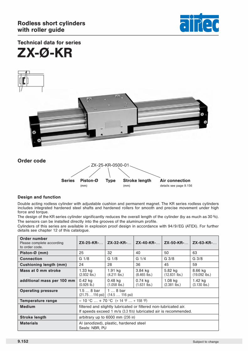
Rodless short cylinderswith roller guide
Technical data for series
ZX-Ø-KR
Design and function
Double acting rodless cylinder with adjustable cushion and permanent magnet. The KR series rodless cylindersincludes integrated hardened steel shafts and hardened rollers for smooth and precise movement under highforce and torque.The design of the KR series cylinder significantly reduces the overall length of the cylinder (by as much as 30 %).The sensors can be installed directly into the grooves of the aluminum profile.Cylinders of this series are available in explosion proof design in accordance with 94/9/EG (ATEX). For furtherdetails see chapter 12 of this catalogue.
Order codeZX-25-KR-0500-01
Series Piston-Ø(mm)
Stroke length(mm)
Air connectiondetails see page 9.156
Type
9.152 Subject to change
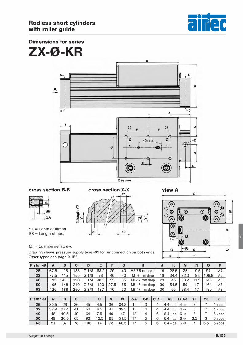
Rodless short cylinderswith roller guide
Dimensions for series
ZX-Ø-KR
view A
(Z) = Cushion set screw.
Drawing shows pressure supply type -01 for air connection on both ends.Other types see page 9.156.
cross section B-B
SA = Depth of threadSB = Length of hex.
cross section X-X
9.153Subject to change
9
Piston-Ø A B C D E F G H J K M N O P25 67.5 95 135 G 1/8 68.2 20 40 M5-7.5 mm deep 19 28.5 25 9.5 97 M432 77.5 115 155 G 1/8 78 40 40 M6-9 mm deep 19 34.4 32.3 9.5 108.8 M540 95 143.5 190 G 1/4 90.5 55 55 M6-12 mm deep 23 45 38.2 11.5 145 M650 105 148 210 G 3/8 120 27.5 55 M8-15 mm deep 30 54.5 59 17 164 M863 125 188 250 G 3/8 137 70 70 M8-17 mm deep 30 55 68.4 17 180 M8
Piston-Ø Q R S T U V W SA SB Ø X1 X2 Ø X3 Y1 Y2 Z25 30.5 26 36 45 4.5 36 34.2 11 3 4 4.4 + 0.2 4 H7 8 7 4 + 0.02
32 32.9 27.4 41 54 6.5 41 39.5 11 4 4 4.4 + 0.2 4 H7 8 7 4 + 0.02
40 48 40.5 49 64 7.5 49 47 12 4 6 6.4 + 0.2 6 H7 8 7 6 + 0.02
50 49 36.5 65 90 12.5 65 51.5 17 5 6 6.4 + 0.2 6 H7 3.5 3 6 + 0.02
63 51 37 78 106 14 78 60.5 17 5 6 6.4 + 0.2 6 H7 7 6.5 6 + 0.02
Series ZXLoad, Force and Torque Data
9.140 Subject to change
V in m/s V in ft/s Factor0.2 0.656 10.3 0.984 0.750.4 1.312 0.50.5 1.640 0.4
0.75 2.460 0.271 3.281 0.2
Information on forces and torques refers to speeds for slide guides (seriesS, K, SG and KG) of ≤ 0.2 m/s (0.656 ft/s) and speeds for roller guides (seriesSR and KR) of ≤ 2 m/s (6.562 ft/s).Where speeds exceed 0.2 m/s (0.656 ft/s) the permissible values of the slideguides are to be multiplied by the loading coefficient (see table on the right).The information on torques refers to the center point of the slide which, inthe case of the ZX-S and ZX-K cylinders, is the center of the tube. In versi-ons with slide guides, the center point of the guide is in the slide.
* Operating force at 6 bar (87 psi). The internal friction is considered.
Loading coefficient
Definition of forces and torques
Complex loadsIf more than one force and torque appear simultaneously, they have to be calculated by the formula:
Fn Fq MI Mq Ms————— + ————— + ————— + ————— + ————— ≤ 1Fn max. Fq max. MI max. Mq max. Ms max.
ZX
Type Operating Fn max. Fq max. Ml max. Mq max. Ms max.force *ZX-25-S 255 N (57 lbf) 270 N (61 lbf) – 13 Nm (9.59 ft. lbf.) 2.5 Nm (1.84 ft. lbf.) 11 Nm (8.11 ft. lbf.)
ZX-25-K 255 N (57 lbf) 270 N (61 lbf) – 8 Nm (5.90 ft. lbf.) 2.0 Nm (1.47 ft. lbf.) 7 Nm (5.16 ft. lbf.)
ZX-25-SG 250 N (56 lbf) 580 N (130 lbf) 580 N (130 lbf) 23 Nm (17.0 ft. lbf.) 10.0 Nm (7.37 ft. lbf.) 23 Nm (17.0 ft. lbf.)
ZX-25-KG 250 N (56 lbf) 340 N (76 lbf) 340 N (76 lbf) 9 Nm (6.64 ft. lbf.) 5.0 Nm (3.69 ft. lbf.) 9 Nm (6.64 ft. lbf.)
ZX-25-SR 250 N (56 lbf) 850 N (191 lbf) 1300 N (292 lbf) 65 Nm (47.9 ft. lbf.) 35.0 Nm (25.8 ft. lbf.) 105 Nm (77.4 ft. lbf.)
ZX-25-KR 250 N (56 lbf) 850 N (191 lbf) 1300 N (292 lbf) 29 Nm (21.4 ft. lbf.) 35.0 Nm (25.8 ft. lbf.) 64 Nm (47.2 ft. lbf.)
ZX-32-S 420 N (94 lbf) 300 N (67 lbf) – 30 Nm (22.1 ft. lbf.) 3.0 Nm (2.21 ft. lbf.) 24 Nm (17.7 ft. lbf.)
ZX-32-K 420 N (94 lbf) 300 N (67 lbf) – 15 Nm (11.1 ft. lbf.) 3.0 Nm (2.21 ft. lbf.) 12 Nm (8.85 ft. lbf.)
ZX-32-SG 410 N (92 lbf) 850 N (191 lbf) 850 N (191 lbf) 33 Nm (24.3 ft. lbf.) 15.0 Nm (11.1 ft. lbf.) 33 Nm (24.3 ft. lbf.)
ZX-32-KG 410 N (92 lbf) 460 N (103 lbf) 460 N (103 lbf) 14 Nm (10.3 ft. lbf.) 6.5 Nm (4.79 ft. lbf.) 14 Nm (10.3 ft. lbf.)
ZX-32-SR 410 N (92 lbf) 900 N (202 lbf) 1500 N (337 lbf) 79 Nm (58.3 ft. lbf.) 40.0 Nm (29.5 ft. lbf.) 125 Nm (92.2 ft. lbf.)
ZX-32-KR 410 N (92 lbf) 900 N (202 lbf) 1500 N (337 lbf) 36 Nm (26.5 ft. lbf.) 40.0 Nm (29.5 ft. lbf.) 76 Nm (56.1 ft. lbf.)
ZX-40-S 655 N (147 lbf) 650 N (146 lbf) – 60 Nm (44.2 ft. lbf.) 4.0 Nm (2.95 ft. lbf.) 54 Nm (39.8 ft. lbf.)
ZX-40-K 655 N (147 lbf) 650 N (146 lbf) – 30 Nm (22.1 ft. lbf.) 4.0 Nm (2.95 ft. lbf.) 27 Nm (19.9 ft. lbf.)
ZX-40-SG 640 N (144 lbf) 1120 N (252 lbf) 1120 N (252 lbf) 60 Nm (44.2 ft. lbf.) 25.0 Nm (18.4 ft. lbf.) 60 Nm (44.2 ft. lbf.)
ZX-40-KG 640 N (144 lbf) 600 N (135 lbf) 600 N (135 lbf) 25 Nm (18.4 ft. lbf.) 11.0 Nm (8.11 ft. lbf.) 25 Nm (18.4 ft. lbf.)
ZX-40-SR 640 N (144 lbf) 1200 N (270 lbf) 2000 N (450 lbf) 190 Nm (140 ft. lbf.) 67.0 Nm (49.4 ft. lbf.) 118 Nm (87.0 ft. lbf.)
ZX-40-KR 640 N (144 lbf) 1200 N (270 lbf) 2000 N (450 lbf) 85 Nm (62.7 ft. lbf.) 67.0 Nm (49.4 ft. lbf.) 72 Nm (53.1 ft. lbf.)
ZX-50-S 1000 N (225 lbf) 800 N (180 lbf) – 80 Nm (59.0 ft. lbf.) 17.0 Nm (12.5 ft. lbf.) 74 Nm (54.6 ft. lbf.)
ZX-50-K 1000 N (225 lbf) 800 N (180 lbf) – 38 Nm (28.0 ft. lbf.) 17.0 Nm (12.5 ft. lbf.) 32 Nm (23.6 ft. lbf.)
ZX-50-SG 1000 N (225 lbf) 1550 N (348 lbf) 1500 N (337 lbf) 200 Nm (147.5 ft. lbf.) 70.0 Nm (51.6 ft. lbf.) 200 Nm (147.5 ft. lbf.)
ZX-50-KG 1000 N (225 lbf) 820 N (184 lbf) 800 N (180 lbf) 60 Nm (44.2 ft. lbf.) 40.0 Nm (29.5 ft. lbf.) 60 Nm (44.2 ft. lbf.)
ZX-50-SR 1000 N (225 lbf) 4100 N (922 lbf) 2000 N (450 lbf) 157 Nm (115.6 ft. lbf.) 45.0 Nm (33.1 ft. lbf.) 170 Nm (125.2 ft. lbf.)
ZX-50-KR 1000 N (225 lbf) 1800 N (405 lbf) 2000 N (450 lbf) 67 Nm (49.4 ft. lbf.) 45.0 Nm (33.1 ft. lbf.) 106 Nm (78.1 ft. lbf.)
ZX-63-S 1600 N (360 lbf) 1400 N (315 lbf) – 110 Nm (81.0 ft. lbf.) 17.0 Nm (12.5 ft. lbf.) 100 Nm (73.7 ft. lbf.)
ZX-63-K 1600 N (360 lbf) 1400 N (315 lbf) – 50 Nm (36.8 ft. lbf.) 17.0 Nm (12.5 ft. lbf.) 48 Nm (35.4 ft. lbf.)
ZX-63-SG 1600 N (360 lbf) 2000 N (450 lbf) 2000 N (450 lbf) 300 Nm (221.2 ft. lbf.) 102.0 Nm (75.2 ft. lbf.) 300 Nm (221.2 ft. lbf.)
ZX-63-KG 1600 N (360 lbf) 1100 N (247 lbf) 1100 N (247 lbf) 105 Nm (77.4 ft. lbf.) 56.0 Nm (41.3 ft. lbf.) 105 Nm (77.4 ft. lbf.)
ZX-63-SR 1600 N (360 lbf) 5000 N (1124 lbf) 2000 N (450 lbf) 196 Nm (144.4 ft. lbf.) 52.0 Nm (38.3 ft. lbf.) 208 Nm (153.2 ft. lbf.)
ZX-63-KR 1600 N (360 lbf) 2500 N (562 lbf) 2000 N (450 lbf) 99 Nm (72.9 ft. lbf.) 52.0 Nm (38.3 ft. lbf.) 134 Nm (98.7 ft. lbf.)
Maximum Force and Torque Data
The mounting surface of the assembled mass should not exceed a straightness tolerance of 0.1 mm to avoidadditional tension or clearance in the guiding system.
Series ZXLoad, Force and Torque Data
Cushioning diagram
Deflection
9.141Subject to change
9
The stroke end cushion must be adjusted to hitchless driving. If the application is out of the diagram range, an exter-nal shock absorber is required. The mounting position of shock absorbers must be close to the center of the mass.The data applies to a horizontal mounting position.
Please abide by the informa-tion given for the maximumForce and Torque Data as seenon page 9.140 this also applieswith additional weight.

Order number Cyl.-Ø A B Radial clearance C
ZXB-25-2025 16° (± 8°) 73 … 75
32 12° (± 6°) 81.4 … 82.4
ZXB-40-20 409° (± 4.5°) 93 … 95
12° (± 6°) 94 … 95± 0.8
507° (± 3,5°) 129 … 130
ZXB-50-2010° (± 5°) 130 … 131
635° (± 2,5°) 144.5 … 145.5
9° (± 4,5°) 145.5 … 146.5
Rodless cylindersAccessories
Mounting parts for series
ZXAlignment coupler ZXB-Ø-20
Materials: Al (anodized)hardened steelbrass
The alignment coupler is designed to be used with external guide systems. This coupler compensates for themis-alignment between the rodless cylinder and the external guide system (supplied by customer). For use withcylinder series ZX-l-K and ZX-l-S.
9.155Subject to change
9
Order number Cyl.-Ø D E F G H K L M
ZXB-25-2025
32 8 54 40 20 80 66 4 x l 6.5 4 x M 6
ZXB-40-20 40
5011 80 51 23 122 102 4 x l 9 4 x M 8ZXB-50-20
63
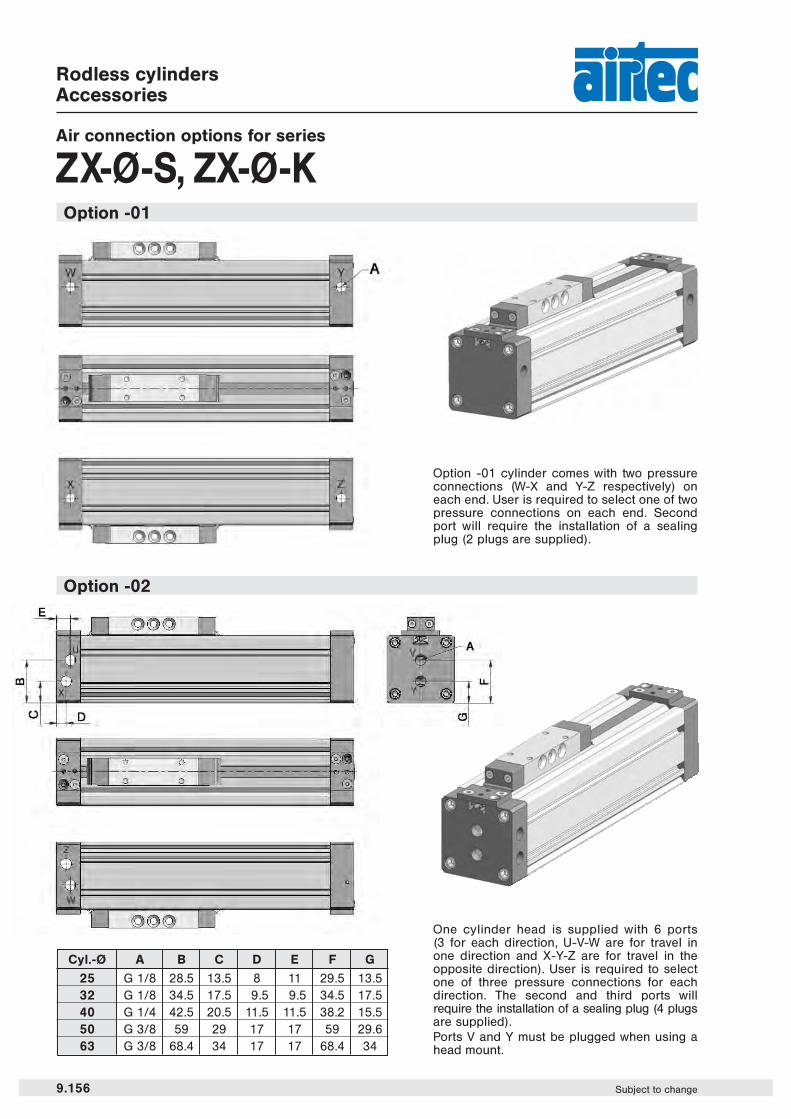
Option -01 cylinder comes with two pressureconnections (W-X and Y-Z respectively) oneach end. User is required to select one of twopressure connections on each end. Secondport will require the installation of a sealingplug (2 plugs are supplied).
Rodless cylindersAccessories
Air connection options for series
ZX-Ø-S, ZX-Ø-K
Option -02
One cylinder head is supplied with 6 ports(3 for each direction, U-V-W are for travel inone direction and X-Y-Z are for travel in theopposite direction). User is required to selectone of three pressure connections for eachdirection. The second and third ports willrequire the installation of a sealing plug (4 plugsare supplied).Ports V and Y must be plugged when using ahead mount.
Option -01
9.156 Subject to change
Cyl.-Ø A B C D E F G
25 G 1/8 28.5 13.5 8 11 29.5 13.532 G 1/8 34.5 17.5 9.5 9.5 34.5 17.540 G 1/4 42.5 20.5 11.5 11.5 38.2 15.550 G 3/8 59 29 17 17 59 29.663 G 3/8 68.4 34 17 17 68.4 34
Rodless cylindersAccessories
Air connection options for series
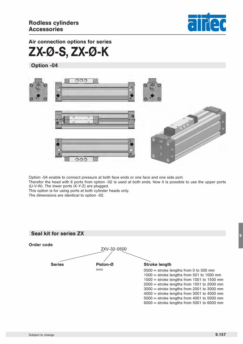
ZX-Ø-S, ZX-Ø-KOption -04
9.157Subject to change
9
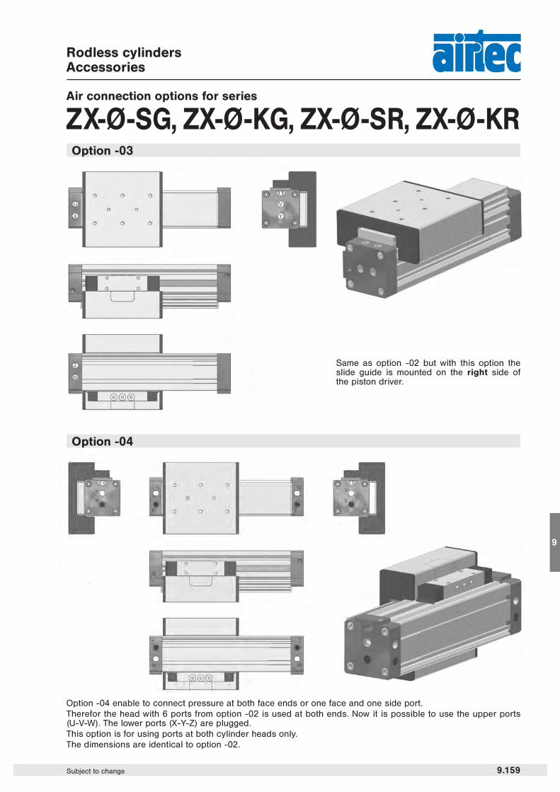
Option -04 enable to connect pressure at both face ends or one face and one side port.Therefor the head with 6 ports from option -02 is used at both ends. Now it is possible to use the upper ports(U-V-W). The lower ports (X-Y-Z) are plugged.This option is for using ports at both cylinder heads only.The dimensions are identical to option -02.
Seal kit for series ZX
Order codeZXV-32-0500
Series Piston-Ø(mm)
Stroke length0500 = stroke lengths from 0 to 500 mm1000 = stroke lengths from 501 to 1000 mm1500 = stroke lengths from 1001 to 1500 mm2000 = stroke lengths from 1501 to 2000 mm3000 = stroke lengths from 2001 to 3000 mm4000 = stroke lengths from 3001 to 4000 mm5000 = stroke lengths from 4001 to 5000 mm6000 = stroke lengths from 5001 to 6000 mm

One cylinder head is supplied with 6 ports (3 for eachdirection, U-V-W are for travel in one direction and X-Y-Zare for travel in the opposite direction). User is required toselect one of three pressure connections for eachdirection. The second and third ports will require theinstallation of a sealing plug (4 plugs are supplied).With this option the slide guide is mounted on the leftside of the piston driver (see view A).Ports V and Y must be plugged when using a head mount.
Rodless cylindersAccessories
Air connection options for series
ZX-Ø-SG, ZX-Ø-KG, ZX-Ø-SR, ZX-Ø-KR
Option -01 cylinder comes with two pressure connections(W-X and Y-Z respectively) on each end. User is requiredto select one of two pressure connections on each end.Second port will require the installation of a sealing plug(2 plugs are supplied).
Option -02
Option -01
view A
9.158 Subject to change
Cyl.-Ø A B C D E F G25 G 1/8 28.5 13.5 8 11 29.5 13.532 G 1/8 34.5 17.5 9.5 9.5 34.5 17.540 G 1/4 42.5 20.5 11.5 11.5 38.2 15.550 G 3/8 59 29 17 17 59 29.663 G 3/8 68.4 34 17 17 68.4 34
Rodless cylindersAccessories
9.159Subject to change
9
Air connection options for series
ZX-Ø-SG, ZX-Ø-KG, ZX-Ø-SR, ZX-Ø-KR
Option -04
Option -04 enable to connect pressure at both face ends or one face and one side port.Therefor the head with 6 ports from option -02 is used at both ends. Now it is possible to use the upper ports(U-V-W). The lower ports (X-Y-Z) are plugged.This option is for using ports at both cylinder heads only.The dimensions are identical to option -02.
Option -03
Same as option -02 but with this option theslide guide is mounted on the right side ofthe piston driver.
Rodless cylindersAccessories
Mounting parts for series
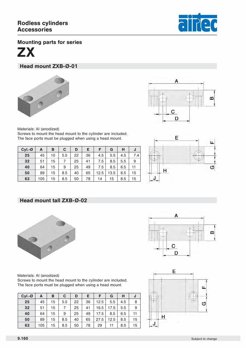
ZXHead mount ZXB-Ø-01
Head mount tall ZXB-Ø-02
Materials: Al (anodized)Screws to mount the head mount to the cylinder are included.The face ports must be plugged when using a head mount.
Materials: Al (anodized)Screws to mount the head mount to the cylinder are included.The face ports must be plugged when using a head mount.
9.160 Subject to change
Cyl.-Ø A B C D E F G H J
25 45 10 5.5 22 36 4.5 5.5 4.5 7.4
32 51 15 7 25 41 7.5 8.5 5.5 9
40 64 15 9 25 49 7.5 8.5 6.5 11
50 89 15 8.5 40 65 12.5 13.5 8.5 15
63 105 15 8.5 50 78 14 15 8.5 15
Cyl.-Ø A B C D E F G H J
25 45 15 5.5 22 36 12.5 5.5 4.5 8
32 51 15 7 25 41 16.5 17.5 5.5 9
40 64 15 9 25 49 17.5 8.5 6.5 11
50 89 15 8.5 40 65 27.5 12.5 8.5 15
63 105 15 8.5 50 78 29 11 8.5 15

Cyl.-Ø A B C D E F G H J K L
25 18 8 15 7.5 5.5 35 45 22 5.5 60 70
32 34 10 15 7.5 6.6 40 51 25 7 73 85
40 26 10 15 7.5 9 40 64 25 9 90.5 105
50 40 15 15 7.5 11 70 89 40 8.5 120 138
63 40 15 15 7.5 11 70 105 50 8.5 136 154
Rodless cylindersAccessories
Mounting parts for series
ZXCenter mount ZXB-Ø-10 with ZXB-Ø-02
Materials: Al (anodized)Screws to mount the head mount to thecylinder are included.The cylinder can be securely mounted byusing two center mounts without theneed for head mounts.
Center mount tall ZXB-32-11 with ZXB-32-02
Materials: Al (anodized)Screws to mount the head mount to thecylinder are included.The cylinder can be securely mounted byusing two center mounts without theneed for head mounts.
Due to the symmetric profile of the cylinder-l 25, 40, 50 and 63, the center mounts can be used on three sidesof the profile. For l 32 the center mount ZXB-32-10 is for use opposite of the carriage only. If mounting is requi-red on the other two sides center mount ZXB-32-11 is required.
9.161Subject to change
9
9.162 Subject to change
Rodless cylindersAccessories
Mounting parts for series
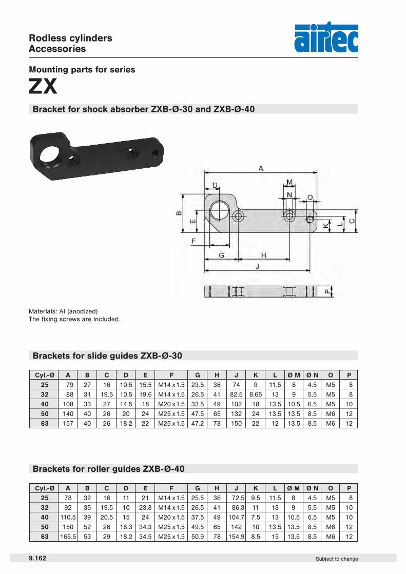
ZXBracket for shock absorber ZXB-Ø-30 and ZXB-Ø-40
Brackets for roller guides ZXB-Ø-40
Materials: Al (anodized)The fixing screws are included.
Brackets for slide guides ZXB-Ø-30
Cyl.-Ø A B C D E F G H J K L Ø M Ø N O P
25 79 27 16 10.5 15.5 M14 x1.5 23.5 36 74 9 11.5 8 4.5 M5 8
32 88 31 19.5 10.5 19.6 M14 x1.5 26.5 41 82.5 8.65 13 9 5.5 M5 8
40 108 33 27 14.5 18 M20 x 1.5 33.5 49 102 18 13.5 10.5 6.5 M5 10
50 140 40 26 20 24 M25 x1.5 47.5 65 132 24 13.5 13.5 8.5 M6 12
63 157 40 26 18.2 22 M25 x 1.5 47.2 78 150 22 12 13.5 8.5 M6 12
Cyl.-Ø A B C D E F G H J K L Ø M Ø N O P
25 78 32 16 11 21 M14 x1.5 25.5 36 72.5 9.5 11.5 8 4.5 M5 8
32 92 35 19.5 10 23.8 M14 x1.5 26.5 41 86.3 11 13 9 5.5 M5 10
40 110.5 39 20.5 15 24 M20 x1.5 37.5 49 104.7 7.5 13 10.5 6.5 M5 10
50 150 52 26 18.3 34.3 M25 x1.5 49.5 65 142 10 13.5 13.5 8.5 M6 12
63 165.5 53 29 18.2 34.5 M25 x1.5 50.9 78 154.9 8.5 15 13.5 8.5 M6 12

Cyl.-Ø Order code max. static force fixing screws max. torque in Nmin N (fixing screws)
25 ZXB-25-31 300 M4 3.1
25 ZXB-25-41 750 M4 3.1
32 ZXB-32-31 900 M5 6.1
32 ZXB-32-41 1000 M5 6.1
40 ZXB-40-31 1490 M6 15.5
40 ZXB-40-41 1760 M6 15.5
50 ZXB-50-31 6900 M8 26
63 ZXB-63-31 6900 M8 26
Cyl.-Ø A B C D E F G H J
25 78.8 23.3 20 41.5 9 11.8 19.3 M14 x1.5 M5
32 87.9 28.6 25 46 10 18.6 23.9 M14 x1.5 M5
40 106.9 31 30 60 14 14 26 M20 x1.5 M5
50 145 40 50 59 17 21 31 M25 x 1.5 M6
63 158.5 47.5 60 56 18 30 38.5 M25 x1.5 M6
9.163Subject to change
Rodless cylindersAccessories
Mounting parts for series
ZXBracket for stroke adjuster/shock absorber ZXB-Ø-31 and ZXB-Ø-41
Materials: Al (anodized)The fixing screws are included.
Brackets for slide guides ZXB-Ø-31
Cyl.-Ø A B C D E F G H J
25 80.9 31.8 20 43.5 11 15.8 27.8 M14 x1.5 M5
32 89.9 37 25 10 10 18.4 31.1 M14 x1.5 M5
40 108.6 35 30 61 14 14.5 30 M20 x1.5 M5
Brackets for roller guides ZXB-Ø-41
Static forces for slide and roller guides
9

Ordertelefon 0479-12600 Orderfax 0479-12719Ändringar förbehållna
ww
w.a
irte
c.s
e
AIRTEC Pneumatic Sweden ABBox 120, Gerfasts väg 6S-283 22 OSBY, Sverige
Telefon +46 (0)479 126 00Telefax +46 (0)479 127 19
Internet www.airtec.seE-post [email protected] Bästa möjliga partner gör skillnad