komatsu style bucket teeth - west-trak new …€¦ · komatsu style bucket teeth ... s-6; din 8559...
TRANSCRIPT
DELIVERING THE SOLUTIONS YOU NEED TO STAY PRODUCTIVE
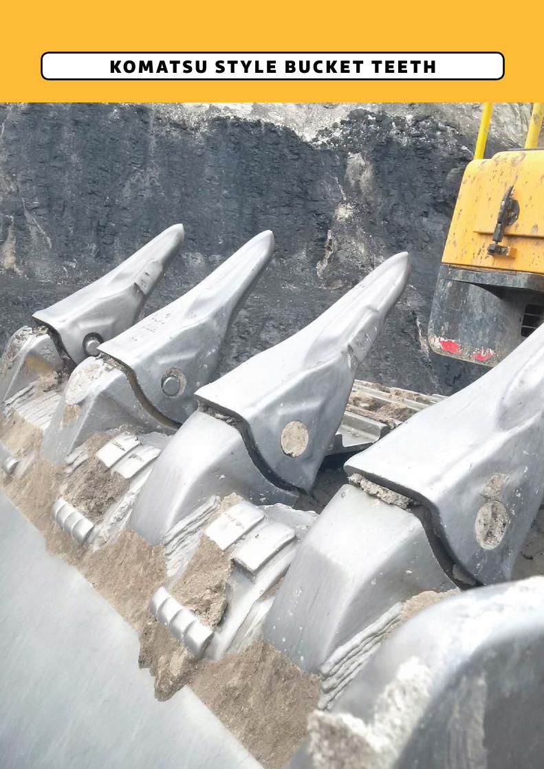
KO M AT S U ST Y L E B U C K E T T E E T H
CALL 0800 654 323 NOW TO DISCUSS YOUR NEEDS
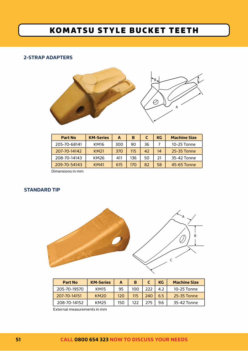
KO M AT S U ST Y L E B U C K E T T E E T H
2-STRAP ADAPTERS
STANDARD TIP
A
B
Part No KM-Series A B C KG Machine Size
205-70-68141 KM16 300 90 36 7 10-25 Tonne
207-70-14142 KM21 370 115 42 14 25-35 Tonne
208-70-14143 KM26 411 136 50 21 35-42 Tonne
209-70-54143 KM41 615 170 82 58 45-65 Tonne
Part No KM-Series A B C KG Machine Size
205-70-19570 KM15 95 100 222 4.2 10-25 Tonne
207-70-14151 KM20 120 115 240 6.5 25-35 Tonne
208-70-14152 KM25 150 122 275 9.6 35-42 Tonne
Dimensions in mm
External measurements in mm
51
A
B
C
C

DELIVERING THE SOLUTIONS YOU NEED TO STAY PRODUCTIVE
TIGER TIP - Premium quality, self sharpening design (MTG)
KO M AT S U ST Y L E B U C K E T T E E T H
Part No KM-Series A B C KG Machine Size
MK200V KM15 98 114 270 4.7 15-25 Tonne
MK300V KM20 122 122 300 6.5 25-35 Tonne
MK400V KM25 148 135 340 9.4 35-42 Tonne
MK650V N/A 180 200 430 22 65-70 Tonne
PIN ASSEMBLY
Pin No A B Machine Size
20X-70-00150 20 71 PC60
09244-02496 25 97 PC200
175-78-21810 25 116 PC300
09244-03036 30 136 PC400
209-70-54240 36 163 PC650
HOW TO IDENTIFY A KOMATSU STYLE TIP
To determine the size or family of a
KOMATSU style tip, whose reference has
disappeared due to wear or any other
reason, take the INTERNAL dimensions A
and B shown below. Don’t take external
measurements because they may have
been aYected by wear.
Dimensions in mm
A B KM/PC Series
75 75 KM15/PC200
95 85 KM20/PC300
112 95 KM25/PC400
130 130 PC650
Looking at the back of tip
External measurements in mm
Dimensions in mm Dimensions in mm
A
B
52
A
B
C
A
B
CALL 0800 654 323 NOW TO DISCUSS YOUR NEEDS
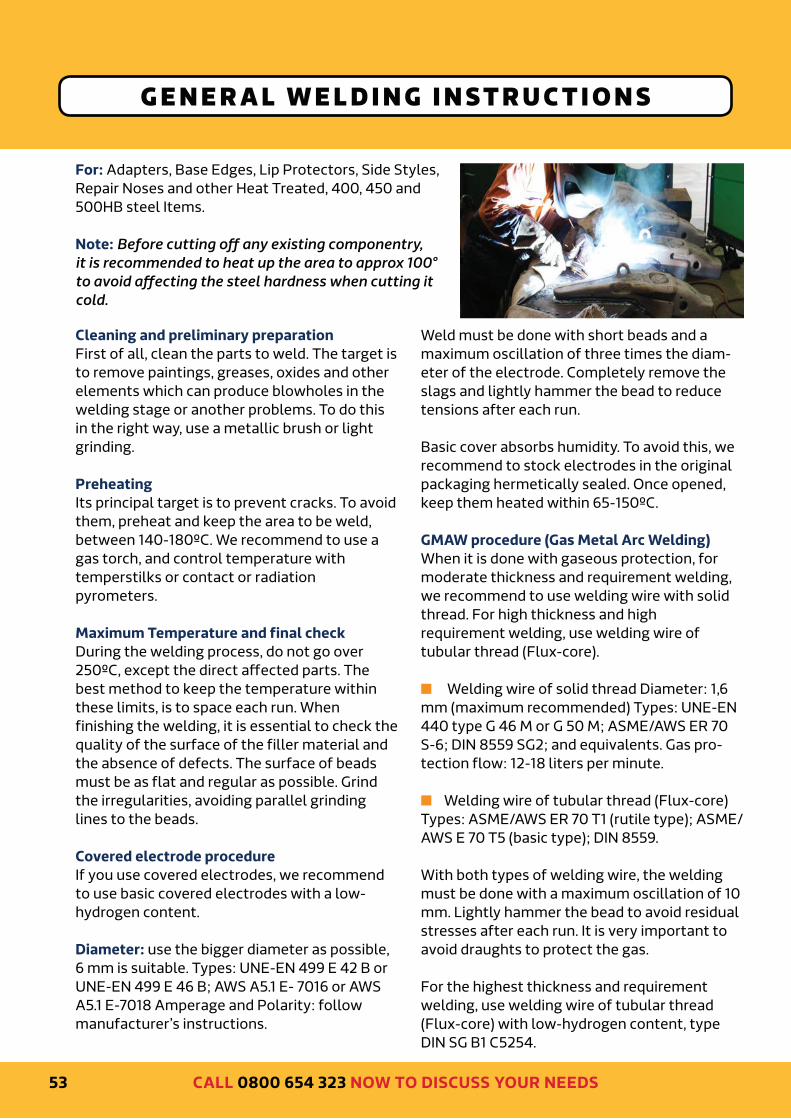
G E N E R A L W E L D I N G I N ST R U C T I O N S
For: Adapters, Base Edges, Lip Protectors, Side Styles,
Repair Noses and other Heat Treated, 400, 450 and
500HB steel Items.
Note: Before cutting o< any existing componentry,
it is recommended to heat up the area to approx 100°
to avoid a<ecting the steel hardness when cutting it
cold.
Cleaning and preliminary preparation
First of all, clean the parts to weld. The target is
to remove paintings, greases, oxides and other
elements which can produce blowholes in the
welding stage or another problems. To do this
in the right way, use a metallic brush or light
grinding.
Preheating
Its principal target is to prevent cracks. To avoid
them, preheat and keep the area to be weld,
between 140-180ºC. We recommend to use a
gas torch, and control temperature with
temperstilks or contact or radiation
pyrometers.
Maximum Temperature and final check
During the welding process, do not go over
250ºC, except the direct aYected parts. The
best method to keep the temperature within
these limits, is to space each run. When
finishing the welding, it is essential to check the
quality of the surface of the filler material and
the absence of defects. The surface of beads
must be as flat and regular as possible. Grind
the irregularities, avoiding parallel grinding
lines to the beads.
Covered electrode procedure
If you use covered electrodes, we recommend
to use basic covered electrodes with a low-
hydrogen content.
Diameter: use the bigger diameter as possible,
6 mm is suitable. Types: UNE-EN 499 E 42 B or
UNE-EN 499 E 46 B; AWS A5.1 E- 7016 or AWS
A5.1 E-7018 Amperage and Polarity: follow
manufacturer’s instructions.
Weld must be done with short beads and a
maximum oscillation of three times the diam-
eter of the electrode. Completely remove the
slags and lightly hammer the bead to reduce
tensions after each run.
Basic cover absorbs humidity. To avoid this, we
recommend to stock electrodes in the original
packaging hermetically sealed. Once opened,
keep them heated within 65-150ºC.
GMAW procedure (Gas Metal Arc Welding)
When it is done with gaseous protection, for
moderate thickness and requirement welding,
we recommend to use welding wire with solid
thread. For high thickness and high
requirement welding, use welding wire of
tubular thread (Flux-core).
n Welding wire of solid thread Diameter: 1,6
mm (maximum recommended) Types: UNE-EN
440 type G 46 M or G 50 M; ASME/AWS ER 70
S-6; DIN 8559 SG2; and equivalents. Gas pro-
tection flow: 12-18 liters per minute.
n Welding wire of tubular thread (Flux-core)
Types: ASME/AWS ER 70 T1 (rutile type); ASME/
AWS E 70 T5 (basic type); DIN 8559.
With both types of welding wire, the welding
must be done with a maximum oscillation of 10
mm. Lightly hammer the bead to avoid residual
stresses after each run. It is very important to
avoid draughts to protect the gas.
For the highest thickness and requirement
welding, use welding wire of tubular thread
(Flux-core) with low-hydrogen content, type
DIN SG B1 C5254.
53
DELIVERING THE SOLUTIONS YOU NEED TO STAY PRODUCTIVE
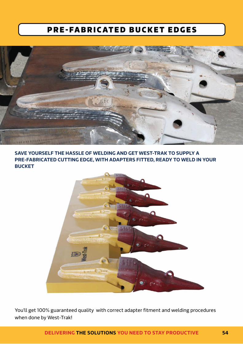
P R E - FA B R I C AT E D B U C K E T E D G E S
SAVE YOURSELF THE HASSLE OF WELDING AND GET WEST-TRAK TO SUPPLY A
PRE-FABRICATED CUTTING EDGE, WITH ADAPTERS FITTED, READY TO WELD IN YOUR
BUCKET
You'll get 100% guaranteed quality with correct adapter fitment and welding procedures
when done by West-Trak!
54

CALL 0800 654 323 NOW TO DISCUSS YOUR NEEDS
CALL 0800 654 323 TODAY FOR YOUR BUCKET TEETH SOLUTIONS
Machine names and part numbers are for reference only.
All parts are high-quality replacement parts and are not produced by the original equipment manufacturers.
Delivering the solutions you need to stay productive