kommunikationsmodul cm-can2 (canopen) - lti motion · user manual cm-can2 de en fr dear user, this...
TRANSCRIPT

G2
CM-CAN2
CDA3000/CDD3000/CTC3000on CANopen Field BusProject Planning, Installation and Commissioning
GB
EN
FR
ES
User ManualCommunication Modulefor CANopen

Overview of documentation
User Manual CM-CAN2
ID no.: 0916.22B0.2-00
Date: 01/2014
Applicable as from software version V1.40 CDA3000
Applicable as from software version V1.10 CDD3000
Applicable as from software version V130.20 CTC3000
Subject to technical changes.
Before purchase
With delivery(depending on supply package)
G2
Catalog
Selecting and ordering a drive system
Operation ManualOperation Manual
KEYPAD KP200Application Manual
Quick and easy initial commissioning
Operation viaKEYPAD KP200
Adaptation of the drive system to the application
CANLust Communication Module Manual
CANopen Communication Module Manual
PROFIBUS-DP Communication Module
Manual
Project planning, installation and
commissioning of the CDA3000/CDD3000/
CTC3000 on the field bus
Project planning, installation and
commissioning of the CDA3000/CDD3000/
CTC3000 on the field bus
Project planning, installation and
commissioning of the CDA3000/CDD3000/
CTC3000 on the field bus
D E F1
G1 G2 G3

DEEN
Dear User,
This manual is intended for you as a project engineer, commissioningengineer or programmer of drive and automation solutions on theCANopen field bus. It is assumed that you are already familiar with this
field bus on the basis of appropriate training and reading of the relevantliterature.
We assume that your drive is already in operation – if not, you should firstconsult the Operation Manual.
Note: This manual applies to the CDA3000 inverter system, the CDD3000 servo system and the CTC3000 direct drive system. The bus interfaces of the CDD3000 and the CTC3000 are identical, so in the following you will see only the abbreviations CDA and CDD used.
How to use this manual
1 General introduction
2 Mounting and connection
3 Commissioning and configuration
5 Control and reference input
7 Fault rectification
1
2
3
4 Device parameter setting 4
5
6 Profile support in detail 6
7
Appendix: Index
A
User Manual CM-CAN2 FR

Pictograms
→ Attention! Misoperation may result in damage to the drive or malfunctions.
→ Danger from electrical tension! Improper behaviour may endanger human life.
→ Danger from rotating parts! The drive may start running automatically.
→ Note: Useful information
User Manual CM-CAN2

DEEN
Table of contents
1 General introduction1.1 Measures for your safety ........................................1-2
1.2 Introduction: CANopen ............................................1-3
1.3 System requirements ..............................................1-4
1.4 Further documentation ...........................................1-4
2 Mounting and connection2.1 Setting the address .................................................2-2
2.2 Mounting .................................................................2-42.2.1 Size BG1...5 .........................................................2-42.2.2 Size BG6...8 .........................................................2-6
2.3 Installation ..............................................................2-72.3.1 Hardware enable (ENPO) ......................................2-82.3.2 LED status display ...............................................2-9
2.4 Transmission speeds ............................................2-10
3 Commissioning and configuration3.1 Commissioning sequence .......................................3-2
3.2 Commissioning instructions ...................................3-5
3.3 Errors in initialization ..............................................3-5
3.4 Test on higher-order controller ..............................3-5
3.5 Data handling ..........................................................3-63.5.1 Saving settings ....................................................3-63.5.2 Restoring factory defaults ....................................3-6
User Manual CM-CAN2 FR

4 Setting the device parameters4.1 Parameter channel (Service Data Objects) ............4-24.1.1 Data types ........................................................... 4-34.1.2 Representation of data types in the
control protocol ...................................................4-4
4.2 Configuration of the drive unit by way of preset application data sets ..............................................4-5
4.3 Parameters for bus operation ................................4-74.3.1 CDA3000/CDD3000 parameters for
bus operation ...................................................... 4-74.3.2 General bus settings ............................................4-94.3.3 Definition of control location and
reference channel .............................................. 4-124.3.4 Data backup ......................................................4-15
4.4 Examples of SDO handling ...................................4-15
4.5 Downloading parameter data sets .......................4-18
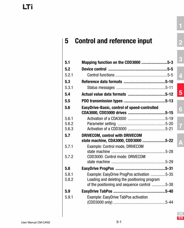
5 Control and reference input5.1 Mapping function on the CDD3000 ........................5-3
5.2 Device control .........................................................5-55.2.1 Control functions .................................................5-5
5.3 Reference data formats ........................................5-105.3.1 Status messages ...............................................5-11
5.4 Actual value data formats ....................................5-12
5.5 PDO transmission types .......................................5-13
5.6 EasyDrive-Basic, control of speed-controlled CDA3000, CDD3000 drives ....................................5-15
5.6.1 Activation of a CDA3000 .................................... 5-195.6.2 Parameter setting .............................................. 5-205.6.3 Activation of a CDD3000 .................................... 5-21
User Manual CM-CAN2

DEEN
5.7 DRIVECOM, control with DRIVECOM state machine, CDA3000, CDD3000 ......................5-22
5.7.1 Example: Control mode, DRIVECOM state machine ....................................................5-28
5.7.2 CDD3000: Control mode: DRIVECOM state machine ....................................................5-29
5.8 EasyDrive ProgPos ................................................5-315.8.1 Example: EasyDrive ProgPos activation ..............5-355.8.2 Loading and deleting the positioning program
of the positioning and sequence control .............5-38
5.9 EasyDrive TabPos ..................................................5-405.9.1 Example: EasyDrive TabPos activation
(CDD3000 only) ..................................................5-44
5.10 EasyDrive DirectPos ..............................................5-455.10.1 Example: Easy-Drive DirectPos activation
(CDD3000 only) ..................................................5-48
5.11 CDD3000, synchronism (electronic gearing) .......5-505.11.1 Example: Easy-Drive Synchron activation ...........5-53
6 Profile support in detail6.1 Time response, PDO and SDO .................................6-2
6.2 DS301 boot-up ........................................................6-36.2.1 Bus message after system start ...........................6-46.2.2 Influence of the DRIVECOM state machine
on CANopen NMT .................................................6-56.2.3 Influence of CANopen NMT on the DRIVECOM
State machine ......................................................6-6
6.3 Sync object ..............................................................6-8
6.4 Emergency object ...................................................6-9
6.5 Node Guarding .......................................................6-106.5.1 Monitoring by Node/Life Guarding ......................6-10
6.6 Default setting of communication objects ...........6-11
6.7 Object directory DS-301/DS-402 ..........................6-12
User Manual CM-CAN2 FR

6.8 Default setting of DS301/402 objects ..................6-14
6.9 EDS device file ......................................................6-156.9.1 How do I create the EDS device file? .................. 6-15
6.10 Saving the CANopen settings ...............................6-15
6.11 Restoring factory defaults ....................................6-16
7 Error rectification7.1 Troubleshooting ......................................................7-1
7.2 Resetting an error ...................................................7-37.2.1 Error acknowledgment via bus system ................ 7-37.2.2 Error acknowledgment, general ........................... 7-3
7.3 Emergency error codes table .................................7-77.3.1 Standard error messages of the CDA3000 ...........7-77.3.2 Description of communication errors ................... 7-8
Appendix Glossary
Appendix Index
User Manual CM-CAN2

DEEN
1
2
3
4
5
6
7
A
1 General introduction
1.1 Measures for your safety ........................................1-2
1.2 Introduction: CANopen ............................................1-3
1.3 System requirements ..............................................1-4
1.4 Further documentation ...........................................1-4
The term “master” as used in the following designates a higher-ordercontroller which organizes the bus system.
The terms “drive unit” and “slave” as used in the following represent aninverter or servocontroller.
User Manual CM-CAN2 1-1

1 General introduction
1.1 Measures for your safety
The CDA/CDD3000 drive units are quick and safe to handle. For your ownsafety and for the safe functioning of your device, please be sure toobserve the following points:
Read the Operation Manual first!
• Follow the safety instructions!
Electric drives aredangerous:
• Electrical voltages > 230 V/460 V:Dangerously high voltages may still be present 10 minutes after the power is cut. You should therefore always checkthat no power is being applied!
• Rotating parts
• Hot surfaces
Your qualification:
• In order to prevent personal injury and damage to property, only personnel with electrical engineering qualifications may work on the device.
• Knowledge of national accident prevention regulations (e.g. VBG 4 in Germany)
• Knowledge of layout and interconnection with the CAN-Bus field bus
During installation observe the following instructions:
• Always comply with the connection conditions and technical specifications.
• Electrical installation standards, such as cable cross-section, shielding, etc.
• Do not touch electronic components and contacts (electrostatic discharge may destroy components).
1-2User Manual CM-CAN2

1 General introduction
1
2
3
4
5
6
7
A
1.2 Introduction: CANopen
CANopen is an interconnection concept based on the CAN (ControllerArea Network) serial bus system. CAN has many specific advantages, inparticular multi-master capability, real-time capability, resistant responseto electromagnetic interference and the high level of availability and lowcost of controller chips. These advantages have resulted in CAN beingintroduced into widespread use in automation too.
In the past, manufacturer and application specific conventions wereapplied in the majority of CAN networks relating to the use and content ofCAN telegrams. Lust Antriebstechnik, too, has defined its own usage ofthe CAN Application Layer (CAL) - CANLust.
Simplified cross-manufacturer communication
The integration of any number of devices in a manufacturer-specificnetwork involves substantial expense. CANopen was developed to solvethis problem. In CANopen the use of CAN identifiers (messageaddresses), the time response on the bus, the network management (e.g.system start and user monitoring) and coding of the data contents isspecified in a uniform way. CANopen makes it possible for devices fromdifferent manufacturers to communicate in a network at minimal cost.
CANopen uses a subset of the communication services offered by CAL todefine an open interface. The selected CAL services are summarized in a“user guide”, as it were. This guide is designated the CANopenCommunication Profile.
CANopen functionality of the CDA3000/CDD3000
The CANopen Communication Profile is documented in the CiA DS-301,and regulates “how” communication is executed. It differentiates betweenProcess Data Objects (PDOs) and Service Data Objects (SDOs). TheCommunication Profile additionally defines a simplified networkmanagement system.
Based on the communication services of the DS-301, the device profilefor variable-speed drive DS-402 was created. It describes the operationmodes and device parameters supported.
In addition to the functions defined in the profiles there are more detailedmanufacturer-specific add-ons. The DS-301 profile is implemented in theCDA3000/CDD3000. The DS-402 supports the obligatory elements suchas control word, status word and operation modes. The CDA3000/CDD3000 parameters are a manufacturer-specific add-on.
The following sections will provide you with an overview of the CANopenfunctionality integrated into the CDA3000/CDD3000. There then followsthe information necessary for commissioning.
User Manual CM-CAN2 1-3

1 General introduction
1.3 System requirements
It is assumed you have a standard CANopen setup program and aCANopen interface driver. For the precise protocol definitions refer to theCAL specification.
With the aid of these objects it is possible to configure the actualCANopen communication very flexibly and adapt it to the specific needsof the user.
1.4 Further documentation
• Operation Manual, for commissioning of the drive unit
• Application Manual, for additional parameter setting to adapt to the application. The Application Manual can be downloaded as a PDF file from our website at http://www.lust-tec.de. Follow the Service link.
• Engineering Guide CDA3000
• CiA DS-301: CAL based Communication Profile for Industrial Systems
1-4User Manual CM-CAN2

DEEN
1
2
3
4
5
6
7
A
2 Mounting and connection
2.1 Setting the address .................................................2-2
2.2 Mounting .................................................................2-42.2.1 Size BG1...5 .........................................................2-42.2.2 Size BG6...8 .........................................................2-6
2.3 Installation ..............................................................2-72.3.1 Hardware enable (ENPO) ......................................2-82.3.2 LED status display ...............................................2-9
2.4 Transmission speeds ............................................2-10
Attention: Do not insert or withdraw modules in operation!
User Manual CM-CAN2 2-1

2 Mounting and connection
2.1 Setting the address
Four possible methods of address assignment
1. Bus address parameter 580-COADR:By way of parameter 580-COADR on the “Bus systems” screen of the DRIVEMANAGER user interface an address from 0 to 127 can be set. If the setting 0 is selected in parameter COADR, one of the following codings is enabled.
2. Connector coding via connectors X11 and X12: By way of the pins on connectors X11 and X12 labeled ADRx, the device address can be binary coded with PIN 1 in the connector by soldering-in jumpers. By means of the two connectors an address between 0 and 63 can be selected.
Note: The 24V supply is connected-through at connectors X10, X11 and X12. The terminals of connectors X11 and X12 are interconnected internally 1 : 1.
Step Action Comment
1 Find out which address is assigned to the module you are installing.
Ask your project engineer.
2
Select the mode of addressing: • by bus address parameter or• by coding on connectors X11 and X12
or• by coding on connector X13 or• by coding switches S1 and S2.
See below
Address setting finished; for further procedure see Installation.
X10 Assignment X11 Assignment X12 Assignment
1 +24 V 1 ADR_POT 1 ADR_POT
2 GND (CAN_GND) 2 CAN_LOW 2 CAN_LOW
3 CAN_GND 3 CAN_GND
Example for addr. 5 Dec: 4 ADR0 4 ADR3
5 ADR1 5 ADR4
6 GND (CAN_GND) 6 GND (CAN_GND)
7 CAN_HIGH 7 CAN_HIGH
8 ADR2 8 ADR5
9 +24 V 9 +24 V
Table 2.1 Pin assignment with a connector coding example
X11
X12
H4H5
X10
12
CM-CAN2
X11
1
21 20
22
ADR_POT
2-2User Manual CM-CAN2

2 Mounting and connection
DEEN
1
2
3
4
5
6
7
A
3. Connector coding via connector X13:By way of the pins on connector X13 labeled ADRx, the device address can be coded with PIN 1 in the connector by soldering-in jumpers. An address between 1 and 127 can be selected.
4. Coding switches S1 and S2:By way of the two coding switches on the top of the CM-CAN2 a hexadecimal address between 1 and 127 can be selected.
Attention: The device address coded on the connector is only used if parameter 580-COADR is set to 0. All hardware codings of the three connectors and coding switches are internally linked by a logical OR operator.
X13 Assignment
1 ADR_POT
2 ADR0
3 ADR1
4 ADR2Example for address 18 Dec:
5 ADR3
6 ADR4
7 ADR5
8 ADR6
9 +24 V
Table 2.2 Pin assignment X13 with an example of connector coding
Example for address 18 Dec = 12 Hex
Figure 2.1 Example of use of the coding switches
X13
1
23 22 21 20
25 24
ADR_POT
S2 S1
456789ABCDEF0
23 456789ABCDEF01
31 2
User Manual CM-CAN2 2-3

2 Mounting and connection
2.2 Mounting Mounting of the communication module on the drive unit is based on thedesign size:
2.2.1 Size BG1...5 Precondition:
• It is assumed that the drive unit is installed and commissioned into operation with the aid of the Operation Manual.
Size Mounting Further ref.
BG1...5(0,37 ... 15 kW)
Side, at least 35 mm mounting distance, if module is to be changed while fitted: Minimum clearance 50 mm
Section 2.2.1
BG6...8(22 ... 90 kW)
On front, mounting package MP-UMCM required
Section 2.2.2
Table 2.3 Mounting the communication module
Step Action Comment
1 Make sure the power supply to the drive unit is cut.
2Connect the CM-CAN2 to the drive unit as shown in Figure 2.2. Use only the slot at the top.
The module lock must engage audibly.The bottom slot is reserved for the UM-xxxx module.
Mounting is complete. To continue see section 2.3 “Installation”.
2-4User Manual CM-CAN2

2 Mounting and connection
DEEN
1
2
3
4
5
6
7
A
Figure 2.2 Mounting for BG1...5
X5
X6
X7
X4
X2
X1
X3
AN
TR
IEB
ST
EC
HN
IK
CD
D3
2.0
08
,C1
.0
In:
23
0 V
+ 1
5/-
20
%5
0/6
0 H
z 3
,0 k
VA
3x
0-2
30
V
7,1
A 0
-40
0 H
z
D-3
5633
Lah
nau
Ou
t:
SN
.:0
02
30
12
71
H1 H2 H3
ACHTUNGKondensatorent-
ladezeit >3 Min.
Betriebsanleitung
beachten!WARNINGcapacitor disscharge
time >3 minutes.
Pay attention to the
operation manual!
ATTENTION
temps de decharge
du condensteur
>3 min. observer le
mode dèmploi!
!
1
20
Ty
pe
:C
DD
32
.00
4,C
1.0
In:
23
0 V
+ 1
5/-
20
%5
0/6
0 H
z 3
,0 k
VA
3x
0-2
30
V
4
A 0
-40
0 H
zO
ut:
SN
.: 0
01
40
17
22
12
SN.:
000.000.00000000
Typ:
Netz:
Ausg.:
klick!
35mm
CM-xxxx
12
A
B
H1 H2 H3
X4
X2
X1X3
ACHTUNGKondensatorent-ladezeit >3 Min.Betriebsanleitungbeachten!
WARNINGcapacitor disschargetime >3 minutes.Pay attention to theoperation manual!ATTENTIONtemps de dechargedu condensteur>3 min. observer lemode dèmploi!
!
H1 H2 H3
X4
X2
X1X3
ACHTUNGKondensatorent-ladezeit >3 Min.Betriebsanleitungbeachten!
WARNINGcapacitor disschargetime >3 minutes.Pay attention to theoperation manual!ATTENTIONtemps de dechargedu condensteur>3 min. observer lemode dèmploi!
!
H1 H2 H3
X4
X2
X3
WAR
NING
capa
cito
r dis
scha
rge
time
>3
min
utes
.Pa
y at
tent
ion
to th
eop
erat
ion
man
ual!
ATTE
NTIO
Nte
mps
de
dech
arge
du c
onde
nste
ur>
3 m
in. o
bser
ver l
em
ode
dèm
ploi
!
!
SN.:000.000.00000000
Typ:
Netz:Ausg.:
X1
L3
U
V
W
RB+
RB
L-
L1
L2
ACHT
UNG
Kond
ensa
tore
nt-
lade
zeit
>3
Min
.Be
trieb
sanl
eitu
ngbe
acht
en!
12
SN.:
000.000.00000000
Typ:
Netz:
Ausg.:
klick!
X735mm
CM-xxxx
12
A
B
User Manual CM-CAN2 2-5

2 Mounting and connection
2.2.2 Size BG6...8
Figure 2.4 Mounting with size BG6...8
Attention: Module Do not insert or withdraw modules in operation!
Step Action Comment
1 Make sure the power supply to the drive unit is cut.
2 Open the device cover.
3
Click the module into the mounting bracket. For positioning and orientation refer to Figure 2.4 (A).
The bracket is part of the MP-UMCM mounting package (see Figure 2.3).
4 Bolt the bracket onto the bottom slot position - see Figure 2.4 (B).
The CM module is thereby placed on its head and the rear of the module is facing forward.
5 Connect the module by the ribbon cable as shown in Figure 2.4 (C).
The ribbon cable is part of the MP-UMCM mounting package (see Figure 2.3).
Mounting is complete. To continue see section 2.3 “Installation”.
Figure 2.3 Mounting package
L+L2 RBL-L1 L3 U V W
H1 H2 H3
X4
startenter
stopreturn
VAL
Hz
X7
X7
12
SN.:
000.000.00000000
Typ:
Netz:
Ausg.:klick!
A
B
C
2-6User Manual CM-CAN2

2 Mounting and connection
DEEN
1
2
3
4
5
6
7
A
2.3 Installation
Figure 2.5 System connection. (1) Bus termination plug
Step Action Comment
1 Connect the module to the field bus. Use a cable conforming to the specification.
Use a bus termination plug (120 Ω) on the last module - see Figure 2.5.
2Make sure the hardware enable is wired on the CDA3000 (X2/8) or CDD3000 (X2/7).
see section 2.3.1
3 Wire the supply voltage to X10, X11 or X12.
18 ...30 VDC, see section 2.1
4 Switch on the drive unit.
Installation is complete. To continue see section 3 “Commissioning and configuration”.
L-L1 L+N
24 VDC
CAN-Bus
12
12
Slave 2
M3~
Slave 1
M3~
1112
1314
1516
1718
1920
12
34
56
78
910
1112
1314
1516
1718
1920
12
34
56
78
910
SPS/PLC
12
Slave n
M3~
(1)
1 120 Ω2
7
User Manual CM-CAN2 2-7

2 Mounting and connection
2.3.1 Hardware enable (ENPO)
The drive units have an additional power stage hardware enable (ENPO)via control terminalX2/8 CDA3000X2/7 CDD3000(also termed “controller enable”). This input must also be configured foroperation over the field bus.
This control signal is high-active. When this control signal is removed themotor runs down uncontrolled (refer also to the description in theOperation Manual).
Figure 2.6 Configuration of controller enable ENPO on the CDA3000
Figure 2.7 Configuration of controller enable ENPO on the CDD3000
Characteristics CM-CAN2
Voltage supply24 V (18 ... 30 V), supply optionally via X10, X11 or X12
Voltage ripple max. 3 Vss
Current consumption max. 80 mA per user
Cable type 9-wire, surge impedance 120 Ω
Table 2.4 CAN bus connection specification
X2 Des. Function
9 ISD00 Digital input 1
8 ENPO Power stage hardware enable
7 UVAuxiliary voltage 24 V
6 UV
X2 Des. Function
7 ENPO Power stage hardware enable
6 DGND Digital ground
5 UV Auxiliary voltage 24 V
ENPO
ENPO
2-8User Manual CM-CAN2

2 Mounting and connection
DEEN
1
2
3
4
5
6
7
A
2.3.2 LED status display
For initial system diagnosis during commission-ing, the communication module has two LEDs(H4 and H5).
These LEDs indicate three different bus states.
H4 redH5
greenBus state CM-CAN2
24V supply to module missing or drive unit is off.
Operational status:SDO communication and PDO communication possible.
10Hz 10Hz
Initialization: Parameter description of drive unit is read-in from option module (approx. 20 sec.). The operation must not be interrupted, as initialization is carried out only once.
10Hz The communication module waits until the drive unit is ready.
1Hz Preoperational status: SDO communication possible.
1Hz Error (in case of error NMT status Preoperational)
Table 2.5 LED status display
H4H5
X10
12
User Manual CM-CAN2 2-9

2 Mounting and connection
2.4 Transmission speeds
The CAN bus can be operated at the following Baud rates:
When selecting the transfer rate it should, however, be ensured that theline length does not exceed the permissible line length for the transferrate in question.
Transmission speedMaximum line length
across the complete network
1000 kBaud 40 m
500 KBaud 100 m Factory setting
125 KBaud 450 m
25 KBaud 1,000 m
Table 2.6 Transmission speeds
2-10User Manual CM-CAN2

DEEN
1
2
3
4
5
6
7
A
3 Commissioning and configuration
3.1 Commissioning sequence .......................................3-2
3.2 Commissioning instructions ...................................3-5
3.3 Errors in initialization ..............................................3-5
3.4 Test on higher-order controller ..............................3-5
3.5 Data handling ..........................................................3-63.5.1 Saving settings ....................................................3-63.5.2 Restoring factory defaults ....................................3-6
User Manual CM-CAN2 3-1

3 Commissioning and configuration
3.1 Commissioning sequence
Preconditions:
• The drive unit is wired as specified in the Operation Manual and first commissioning is complete. (To test CAN communication, it is suffi-cient to connect the mains voltage and activate the ENPO signal (hardware enable) at connector X2.)
• The communication module is plugged into option slot 2 (see section 2.2, “Mounting”).
Figure 3.1 If the initialization is correct slot 2 shows: CANopen
Step Action Comment
1 Check the wiring. Make sure hardware enable ENPO (X2) is not connected.
2Switch on the supply voltage. The green LED H5 on the CM-CAN2 communication module flashes.
H5 flashes rapidly [10 Hz] on initial power-up for a period of approx. 10 s or slowly [1 Hz] when initialization is complete.
3
If the initialization completed correctly, for slot 2 under its “Actuals-Slots” menu item the DRIVEMANAGER displays CANopen. Please check the parameter (see Figure 3.1).
If it does not show the value, refer to section 3.3.
3-2User Manual CM-CAN2

3 Commissioning and configuration
DEEN
1
2
3
4
5
6
7
A
Figure 3.2 Saving settings
Step Action Comment
4 Configure the drive unit using the Appli-cation Manual.
(Inputs/outputs, software func-tions, ...)
5Test the control quality and optimize the controller settings as necessary using the Operation Manual.
6 Set the relevant preset solution according to the Application Manual.
For an initial test of CAN communication the following settings are required as a minimum: see Table 3.1.
7 Test the drive on the higher-order controller, see section 3.4.
8 Finally, save the setting with the -> button.
see Figure 3.2
User Manual CM-CAN2 3-3

3 Commissioning and configuration
For more detailed information on optimization of the software functionsand control circuits refer to the device application manual.
Parameter Value Comments
581-COBDR Baud rateBaud rate setting, factory setting = 500 kB, see section 4.3.2
580-COADR Address Device address, factory setting = 0, or HW coding
260 -CLSEL (5) OPTN2 Assign control location to CANopen
280 -RSSL1 (7) FOPT2 Apply reference value from CANopen
150-SAVE (1) START Finally, save settings in device
Table 3.1 Minimum parameters to be set
3-4User Manual CM-CAN2
3 Commissioning and configuration
DEEN
1
2
3
4
5
6
7
A
3.2 Commissioning instructions
For a variety of reasons, it may be that a drive unit does not respond to atelegram:
• There is no reply if the telegram frame (baud rate, data length) on the master computer is not correct.
• There is no reply if a drive unit is addressed with the wrong bus address.
• There is no reply if the serial connection between the master computer and the drive unit is not correctly set up.
• There is no reply if the 24V supply to the communication module is missing or the cabling is faulty.
• There is no valid reply if several devices with the same device address are connected to the bus.
3.3 Errors in initialization
If the slot identifier (parameter 578-OPTN2) shows the value NONE,there is either a fault in the drive unit or in the communication module. Tolocalize the defective component, you should first reset the drive unit to itsfactory defaults. To do so, either set parameter 4-PROG = 1 or press andhold down the two cursor keys on the KP200 control unit during the self-test period after power-on.
When the reset is complete, you can verify the value in parameter 578-OPTN2 = COPEN once again. If it still shows NONE, cut the mains powerand plug the communication module into the other option slot to test it. Ifthe module is not correctly detected there either, there is a hardware faultin the module or in the drive unit.
3.4 Test on higher-order controller
To activate changed settings the device must be switched off and back onagain. When the power is connected, after an initialization period of a fewseconds the device must transmit a one-off boot-up message (ID 80h +Node ID = 81h at device address 1). If this happens, the communicationis OK.
Note: In transmissions the number of data bytes does not neces-sarily have to be taken into account, but it is advantageous.
User Manual CM-CAN2 3-5

3 Commissioning and configuration
3.5 Data handling
3.5.1 Saving settings All configuration data can be backed-up on a SMARTCARD or with theDRIVEMANAGER as a file. A parameter set in the DRIVEMANAGER alwayscomprises three files with the extensions *.00D, *.00T and *.00X. TheDRIVEMANAGER file selection boxes only ever display the *.00D file.
3.5.2 Restoring factory defaults
There are two possible ways of restoring the factory defaults of thedevices:
• Set parameter 04-PROG (subject area _86SY System) to 1. All device parameters (device configuration only, without motor and loop control parameters) up to user level 4 are reset to their factory defaults.
• Set parameter 04-PROG to 850. All device parameters up to user level 5 (Service) are reset to their factory defaults. That means including motor and loop control parameters.
• From the main window menu of the DRIVEMANAGER under “Active device” select “Reset to factory defaults”.
• Press and hold down both cursor keys on the KEYPAD KP200 control unit during power-on. All device parameters up to user level 5 are reset to their factory defaults.
Note: In both cases it takes around 10 seconds for the device to signal that it is ready again. During this time the device performs a self-test and changes all its settings to the factory setting. This setup is only retained when the data are saved in the device, however. Data backup is initiated by way of the DRIVEMANAGER user interface or by writing parameter 150-SAVE = 1 by way of the bus system.
Attention: Data backup takes a few hundred milliseconds. During that time the device must not be switched off, other-wise the settings will be lost.
Parameter 150-SAVE is automatically set to 0 by the device after thesave operation. This process can be used for timeout monitoring of thefunction.
3-6User Manual CM-CAN2

DEEN
1
2
3
4
5
6
7
A
4 Setting the device parameters
4.1 Parameter channel (Service Data Objects) ............4-24.1.1 Data types ...........................................................4-34.1.2 Representation of data types in the
control protocol ....................................................4-4
4.2 Configuration of the drive unit by way of preset application data sets ..............................................4-5
4.3 Parameters for bus operation .................................4-74.3.1 CDA3000/CDD3000 parameters for
bus operation .......................................................4-74.3.2 General bus settings ............................................4-94.3.3 Definition of control location and
reference channel ..............................................4-124.3.4 Data backup ......................................................4-15
4.4 Examples of SDO handling ....................................4-15
4.5 Downloading parameter data sets .......................4-18
User Manual CM-CAN2 4-1

4 Setting the device parameters
4.1 Parameter channel (Service Data Objects)
The Service Data Object (SDO) permits write and read access to theobject directory. This SDO is implemented according to the CALspecification by the Multiplexed Domain CMS object. The protocol isdesigned for the transfer of data of any length. For SDO transfer a so-called SDO Client is integrated into the device. Communication is by wayof two reserved identifiers.
Figure 4.1 Example of an SDO data transfer in Expedited mode
The CAL specification makes a basic distinction between three protocolservices:
• Download protocol (Write)
• Upload protocol (Read)
• Abort protocol (Error)
The upload and download protocols additionally differentiate between:
• Expedited Multiplexed Domain Protocol, for access to objects with a data length of up to 4 bytes (shown above) and
• Multiplexed Domain Protocol, for access to objects of any length
Receive SDO: 600 h
Transmit SDO: 580 h
SDO-Client SDO-Server
Object directory
Drive controller
600H + Node-ID Byte 0 1 2 3 4 5 6 7
580H + Node-ID Byte 0 1 2 3 4 5 6 7
Subindex
Index
Control field
Subindex
Index
Control field
Data
4-2User Manual CM-CAN2

4 Setting the device parameters
DEEN
1
2
3
4
5
6
7
A
4.1.1 Data types
Note: By way of the DRIVEMANAGER user interface or the KEYPAD KP200 control unit many parameter settings are displayed in the form of value substitution texts.Example: Parameter 150-SAVE = STOP
When writing and reading over the field bus the corresponding numericalvalues for these value substitution texts must be used. Both in theapplication manuals of the devices and in this document, these valuesare given in brackets () after the value substitution text.
Example: Parameter 152-ASTER = BUS_1 (9)
The drive units support the following parameter data formats:
Data type Value range Function
USIGN8 0...255
UnsignedUSIGN16 0...65535
USIGN32 0...4294967295
INT8 -128...127
Integer, signedINT16 -32768...32767
INT32 -2147483648...2147483647
INT32Q16 -32767,66...32766,99
32-bit number with scaling 1/65536, i.e. the Low word indicates the number of decimal places.
FIXPOINT16 0,00...3276,80Fixed point number with scaling 1/20, i.e. increment size 0.05
FLOAT32 see IEEE32-bit floating point number in IEEE format
ERR_STRUCError number (1 byte), error location (1 byte), error time (2 bytes)
STRINGASCII characters, max. 100 bytes in bus operation incl. zero terminator
Table 4.1 Data types, see Table 4.2
User Manual CM-CAN2 4-3

4 Setting the device parameters
4.1.2 Representation of data types in the control protocol
All data types are represented appropriate to their preceding sign as 32-bit variables in Intel format.
Examples
For detailed information on string parameters see
Data bytes of the control protocol
3 4 5 6
USIGN8/INT8 *USIGN16/INT16 *USIGN32/INT32
Low Word Low Byte
Low Word High Byte
High Word Low Byte
High Word High Byte
INT32Q16 Post-point Low Post-point High Pre-point Low Pre-point High
FIXPOINT16 * See examples
FLOAT32 IEEE format
ERR_STRUC Error number Error location TOP Low TOP High
STRING See examples
* Filled out appropriate to preceding sign (00H or FFH)TOP = Time of Operation in full hours
Table 4.2 Arrangement of data types in the data field
Data type Example LL 3 LH 4 HL 5 HH 6
INT32Q16 10.5 Dec 00 80 H
(0.5 Dec)
0A 00 H
(10 Dec)
FIXPOINT16 10.05 Dec
[ * 20 = 201 Dec]
C9 00 00 00 H
(201 Dec)
ERR_STRUC E-OP2 with error
location 172 with
85 operating hours
10 H
(16 Dec =
E-OP2)
AC H
(172 Dec)
55 00 H
(85 hours TOP)
STRING “Drive unit” 41 H
(A)
44 H
(D)
43 H
(C)
00 H
(End identifier)
Table 4.3 Examples of mapping of data types
4-4User Manual CM-CAN2

4 Setting the device parameters
DEEN
1
2
3
4
5
6
7
A
4.2 Configuration of the drive unit by way of preset application data sets
For detailed information on preset solutions refer to section 4 of therelevant Application Manual.
CDA3000:
The choice can be made between three preset solutions = BUS_1(9) ...BUS_3(11) for operation on field bus systems. These solutions differ onlyin the function of digital inputs on the device. The control location andreference source are assigned to the field bus system. By way ofparameter 152-ASTER this selection/setting can also be made over abus.
CDD3000:
For operation on field bus systems the choice can be made between thefollowing preset solutions:
• SCB_5(9) = Speed control, reference and control via field bus
• SCB_2(4) = Speed control, +/-10V reference, control via field bus
• SCB_3(6) = Speed control, fixed speeds, control via field bus
• SCB_2(3) = Speed control, pulse input, control via field bus
• PCB_4(16) = Positioning, fully programmable, control via field bus
• PCB_3(14) = Positioning, fixed positions, control via field bus
• PCB_2(12) = Positioning, reference and control via field bus
• PCB_1(11) = Electronic gearing, control via field bus
These solutions differ only in the function of digital inputs on the device.The control location and reference source are assigned to the field bussystem. By way of parameter 152-ASTER this selection/setting can alsobe made over a bus.
On the CDA3000 the following parameters are automatically changed inthe device on selection of the “BUS_1(9)” preset solution:
User Manual CM-CAN2 4-5

4 Setting the device parameters
After the automatic configuration the baud rate and device address alsoneed to be set.
Note: If parameters from the above table are changed subsequently, parameter 152-ASTER is automatically set to OFF (0), to indicate a change in the preset solution. The original setting continues to be displayed in parameter 151-ASTPR.
Inputs and outputs are made available to the bus system as decentralizedinputs/outputs by way of the function selector settings. That meansoutputs can be polled directly via the control word and states at inputsdirectly in the status word. By changing the relevant function selectordevice functions can also be assigned to inputs and outputs.
Note: The settings must be backed-up in the device before the reset. These changes only take effect after a mains reset.
ParameterFactory setting
(FS)Changed value Function
151 -ASTPR DRV_1 BUS_1(9) Original application data set
152 -ASTER DRV_1 BUS_1(9) Current application data set
180 -FISA0 OFF OPTN2 Function selector analog standard input ISA00
181 -FISA1 OFF OPTN2 Function selector analog standard input ISA01
210-FIS00 STR OPTN2 Function selector digital standard input ISD00
211-FIS01 STL OPTN2 Function selector digital standard input ISD01
212-FIS02 SADD1 OPTN2 Function selector digital standard input ISD02
213-FIS03 OFF OPTN2 Function selector digital standard input ISD03
240 -FOS00 BRK1 OPTN2 Function selector digital standard output OSD00
241 -FOS01 REF OPTN2 Function selector digital standard output OSD01
242 -FOS02 S_RDY OPTN2 Function selector digital standard output OSD02
260-CLSEL * TERM OPTN2 Control location selector
280-RSSL1 * FMAX FOPT2 Reference selector 1
289 -SADD1 10 0 Reference selector 2
* These parameters must be changed as a minimum in order to enable control via the bus system.
Table 4.4 Presetting based on the example of CDA3000: BUS_1 (9)
4-6User Manual CM-CAN2

4 Setting the device parameters
DEEN
1
2
3
4
5
6
7
A
4.3 Parameters for bus operation
Table 4.5 describes the parameters in the order in which they are mustusefully verified and set.
The following pages present a more detailed description of the individualparameters.
Overview
4.3.1 CDA3000/CDD3000 parameters for bus operation
Describes the parameters in the order in which they are must usefullyverified and set.
The following pages present a more detailed description of the individualparameters.
On the DRIVEMANAGER user interface in version V3.00 and later theparameters are grouped in a dedicated screen for the bus systems:
Subject area Parameter Function Value range FS Your set. Unit
1. General bus settings
_57OP 580-COADR CANopen device address 0 ... 127 0
581-COBDR CANopen baud rate 0 ... 7 2=500kB
575-CASCY Sampling time for status message 1 ... 32000 80 ms
2. Definition of control location and reference channel
_57OP 492 -CACNF CAN configuration 0 ... 4 4
_26CL 260 -CLSEL Control location selector TERM ... OPTN2 TERM(0) OPTN2(4)
_28RS 280 -RSSL1 Reference selector 1 OFF ... FOPT2 FMAX(11) FOPT2(7)
_57OP 573 -CACTR CAN bus control word 0000 h ... FFFF h 0000 h Hex
572-CASTA CAN bus status word 0000 h ... FFFF h 0000 h Hex
_28RS 288 - FOPT2 Reference value of option slot 2 (non-editable) 0 Hz
3. Data backup
_15FC 150-SAVE Back-up device setup STOP, START(1) STOP(0)
FS = Factory setting
Table 4.5 Overview of CDA3000 bus parameters
User Manual CM-CAN2 4-7

4 Setting the device parameters
Figure 4.2 Parameters for bus operation
Subject area Parameter Function Value range FS Your set. Unit
1. General bus settings
Bus systems 492 -CACNF CAN configuration Type of control/
reference transfer
0 ... 8 4
580-COADR CAN bus Device address 0 ... 99 0
581-COBDR CAN bus baud rate 0 ... 7 2=500kB
575-CASCY Sampling time for status message 1 ... 32000 80 ms
570 -CAMOD Option module function selection
CANLUST (inactive, do not change!)
Slave/Master Slave(0)
2. Definition of control location and reference channel
260 -CLSEL Control location selector TERM ... OPTN2 TERM OPTN2(4)
280 -RSSL1 Reference selector 1 OFF ... FOPT2 FMAX FOPT2(7)
573 -CACTR CAN bus control word 0000H ... FFFFH 0000H Hex
Table 4.6 Overview of CDA3000/CDD3000 bus parameters
4-8User Manual CM-CAN2

4 Setting the device parameters
DEEN
1
2
3
4
5
6
7
A
4.3.2 General bus settings
492-CACNF - CAN configuration
The parameter defines the type of activation via CAN. With theDRIVECOM state machine the resolution of the reference input and of theactual value can additionally be varied.
Note: The parameter is automatically set correctly when a preset solution is selected. DRIVECOM activation can be enabled by setting 1-3 only for the EasyDrive Basic solutions. See section 5, Device control.
572-CASTA CAN bus status word 0000H ... FFFFH 0000H Hex
288 - FOPT2 Reference value of option slot 2 (non-editable) 0 Hz
3. Data backup
150-SAVE Back-up device setup STOP, START(1) STOP(0)
FS = Factory setting
Subject area Parameter Function Value range FS Your set. Unit
Table 4.6 Overview of CDA3000/CDD3000 bus parameters
Subject area Value rangeFactory setting
Unit Data type Memory type
_57OP 0...8 4 USIGN8 FLASH
Activation Reference ActualCACNF
No activation No reference transfer All words = 0 0
DRIVECOM state machine 16-bit reference speed (Q0) 16-bit actual speed (Q0) 1
DRIVECOM state machine 32-bit reference speed (Q16) 32-bit actual speed (Q16) 2
DRIVECOM state machine 32-bit reference speed (Q16)16-bit actual speed (Q0)16-bit actual torque (Q0)
3
EasyDrive Basic 32-bit reference speed (Q16) 32-bit actual speed (Q16) 4
Table 4.7 CAN configuration / CDA3000 control mode
User Manual CM-CAN2 4-9

4 Setting the device parameters
580-COADR - CANopen Device address
As described above, the device address can be assigned in four ways.The decisive factor is the setting of parameter 580 -COADR. If theparameter is set to the value 0, the device address is taken from theconnector configuration after the system starts.
Attention: If parameter 580-COADR is set to 0 and the address from the connector configuration also produces the value 0, the device then starts automatically with NodeID 1.
If the parameter is set to values between 1 and 127, the connectorconfiguration is ignored. The inverter starts after the reset with the deviceaddress set in COADR (save the setting prior to the reset with parameter150-SAVE).
Activation Reference ActualCACNF
No activation No reference transfer All words = 0 0
DRIVECOM state machine 16-bit reference speed (Q0) 16-bit actual speed (Q0) 1
DRIVECOM state machine 32-bit reference speed (Q16) 32-bit actual speed (Q16) 2
DRIVECOM state machine 32-bit reference speed (Q16)16-bit actual speed (Q0)16-bit actual torque (Q0)
3
EasyDrive Basic 32-bit reference speed (Q16) 32-bit actual speed (Q16) 4
EasyDrive ProgPosProgPos. Control bits, POMER[90-97], POVAR[98]
ProgPos status bits, POMER[80-87], actual position in distance units
5
EasyDrive TabPosControl bits, P-to-P positioning, table index
Status bits, P-to-P positioning, actual position
6
EasyDrive DirectPosControl bits, P-to-P positioning, position reference
Status bits, P-to-P positioning, actual position
7
EasyDrive Synchron (in preparation)
Control bits, electronic gearing
Status bits, electronic gearing, actual position
8
Table 4.8 CAN configuration / CDD3000 control mode
Subject area Value range Factory set. Unit Data type Memory type
_57OP 0 ... 127 1 – USIGN8 FLASH
4-10User Manual CM-CAN2

4 Setting the device parameters
DEEN
1
2
3
4
5
6
7
A
581-COBDR -CANopen baud rate
The baud rate is set by parameter 581-COBDR.
Attention: A change of device address or baud rate only takes effect after the next reset (restart) of the inverter!Before the reset save the settings in the device with parameter 150-SAVE = 1(START)!
575-CASCY - Sampling time of status message in ms
Parameter to configure the sampling time within which the drive unitindependently transmits a status report.
Condition: Transmission types for TXPDO1 = asynchronous and eventhandling in device set to cyclic send.
Value range Factory set. Unit Data type Memory type
25 ... 500 500 KBaud USIGN8 FLASH
581-COBDR value range
Transmission speed Comments
1 1 MBaud
2 500 KBaud Factory setting
4 125 KBaud
7 20 KBaud
Table 4.9 Baud rate
Value range Factory set. Unit Data type Memory type
1 ... 32000 80 ms USIGN16 FLASH
User Manual CM-CAN2 4-11

4 Setting the device parameters
570-CAMOD - Option module function selection, CANLust
Parameter to configure the function of CANLust. The SLAVE setting
permits control of the device via CAN. The MASTR setting permitsconnection of external I/O add-ons to the option module. This function isin preparation.
4.3.3 Definition of control location and reference channel
260-CLSEL - Control location
The control location is selected by way of parameter 260-CLSEL. WithCLSEL = OPT2 the control word for the device is formed from bytes 0and 1 of RXPDO1.
The control location is set automatically when a preset solution isselected. It should not be changed subsequently, as this may significantlyalter the response of the device on the bus.
Note: Reference and control values and the content of the control identifier are only evaluated in the “operational” state. The control mode and the structure of the control and status words is defined by way of the preset solution (EASYDRIVE, DRIVECOM).
280-RSSL1 - Reference selector
RSSL1 = FOPT2 causes the reference to be formed from the data bytesof RXDPO1.
On the CDD3000 the reference selector is set automatically when apreset solution is selected. It should not be changed subsequently, as thismay significantly alter the response of the device on the bus.
Value range Factory set. Unit Data type Memory type
0 (SLAVE) ...1 (MASTR)
0 (SLAVE) USIGN8 FLASH
Value range Factory set. Unit Data type Memory type
0 (TERM) ... 4 (OPTN2)
0 (TERM) – USIGN8 FLASH
Value range Factory set. Unit Data type Memory type
0 (FCON) ... 11 (FMAX)
11 (FMAX) – USIGN8 FLASH
4-12User Manual CM-CAN2

4 Setting the device parameters
DEEN
1
2
3
4
5
6
7
A
Note: Reference and control values and the content of the control identifier are only evaluated in the “operational” CAN system state.
Other logical settings may also be selected as the reference source:
Online switching between the reference sources is only possible by wayof appropriately parameterized digital inputs (see functions of digitalinputs in the relevant Application Manual).
RSSL1 Function
(1) FA0 Analog input 0
(2) FA1 Analog input 1
(4) FPOT MOP function, only in conjunction with appropriately configured inputs
(5) FDIG Digital reference, see device operation manual
(7) FOPT2 Reference from option slot 2, here CANLUST
(8) TBSELTable references incl. acceleration and braking ramps, selection of table position via bits in the control word or directly in parameter TBSEL or via inputs with function FFTBx
(9) FFIX1/2 Fixed frequency *
(10) FMIN1/2 Minimum output frequency *
(11) FMAX1/2 Maximum output frequency *
* Switchable with characteristic data set switchover, e.g. via bits in the control word
Table 4.10 Settings for reference selector 280-RSSL1 on CDA3000
RSSL1 Function
(1) RA0 Analog input 0
(2) RA1 Analog input 1
(4) FDIG Digital reference, see device operation manual
(6) ROPT2 Reference from option slot 2, here CANLUST
(7) RFIXSpeed table references incl. acceleration and braking ramps, selection of table position via bits in the control word or directly in parameter TBSEL or via inputs with function FFTBx
(8) PTAB Position table references
(9) PMOD ProgPos positioning and sequence control
Table 4.11 Settings for reference selector 280-RSSL1 on CDD3000
User Manual CM-CAN2 4-13

4 Setting the device parameters
573-CACTR - Control word
The control word (data byte 0+1) received via RXPDO1 is entered inparameter 573-CACTR. During commissioning the parameter can beused to check reception of the data. The parameter is for displaypurposes only.
572-CASTA - Status word
The status of the preset state machine is entered in parameter 572CASTA. The data content of the parameter corresponds to data bytes 0and 1 in TXPDO1. The parameter is for display purposes only.
288-FOPT2 - Reference from option slot 2
The reference value received via the control identifier is entered inparameter FOPTx. The data content of the parameter corresponds to thereference data bytes of RXPDO1. The interpretation of the value isdependent on the selected operation mode. The parameter is for displaypurposes only.
Value range Factory set. Unit Data type Memory type
0000 H ... FFFF H 0000 H – USIGN16RAM actual
value
Value range Factory set. Unit Data type Memory type
0000 h ... FFFF h 0000 h – USIGN16RAM actual
value
Value range Factory set. Unit Data type Memory type
-32764 ... 32764 0 Hz INT32Q16RAM actual
value
4-14User Manual CM-CAN2

4 Setting the device parameters
DEEN
1
2
3
4
5
6
7
A
4.3.4 Data backup 150-SAVE - Back-up device setup
Parameter to back-up the complete device setup to the Flash memory. Allparameters are first held only in the RAM. So that the parameters areavailable again after power-off, they must be backed-up. To do so,parameter 150-SAVE is set to 1 after all other parameters have been set.The save operation takes a few hundred milliseconds. During that timethe device must not be switched off, otherwise the settings will be lost.Parameter 150-SAVE is automatically set to 0 by the device after thesave operation. This process can be used for timeout monitoring of thefunction.
4.4 Examples of SDO handling
By way of the Receive SDO (COB IDs: 600 h + Node ID) the CANopenobjects and the parameters of the drive controller can be accessed.
In a data transfer protocol a maximum of 4 data bytes can be transferredin Expedited mode. This means all device parameters, apart from Stringparameters, can be written to with a single transfer protocol.
String parameters can be written to using the Multiplexed Domainprotocol.
Where can I find the device parameters?
All device parameters are addressed by way of a parameter number. Thedrive controller has parameter numbers between 1 and 999.
In addition to the standard objects, the CANopen profile additionallyprovides a range for manufacturer-specific entries. This range liesbetween 2000 h and 5FFF h. If you then want to read or write parameter303-FMAX1 (maximum frequency 1) of the device, the object index isformed from 2000 h + parameter number (Hex).
In our example: Index = 2000 h + 12F h
The entries in the “Control field” area are generated by the CANopen
driver. They are only included to fully document the examples cited. Theentries are dependent on the transferred data.
Value range Factory set. Unit Data type Memory type
0 (STOP) ... 1 (START)
0 (STOP) – USIGN8RAM control
value
User Manual CM-CAN2 4-15

4 Setting the device parameters
Examples:
1. Read standard parameter 390-TYPE [INT32] at CAN address 1Parameter number 390 (186 h) is addressed as a CAN object under the object number 2186 h.
=> Device type 7D08 h = 32008, i.e. CDA32.008
2. Read standard parameter 406-REFF at CAN address 1Parameter number 406 (196 h) is addressed as a CAN object under the object number 2196 h.
3. Read object 1008 h-Device Name at CAN address 1 Standard object 1008 h represents device parameter 130-NAME (data type STRING). In the following example this string parameter has more than 4 characters (“spindle drive 1”) and is read in a Multiplexed Domain protocol.
Enquiry SDO ID: 601 h 40 86 21 0 0 0 0 0
Reply SDO ID: 581 h 43 86 21 0 08 7D 0 0
Enquiry SDO ID: 601 h 40 96 21 0 0 0 0 0
Reply SDO ID: 581 h 42 96 21 0 0 0 0 0
Abs. Time SDO ID data
Introduction of the Multiplexed Domain protocol: 16 characters are to be transmitted.
6.0011 Tx 602 [1008,00] Initiate Upload Rq.
6.0426 Rx 582 [1008,00] Initiate Upload Rsp Bytes: 00000010
The first 7 characters “Spindle” are transmitted.
6.0434 Tx 602 Upload Segment Rq. T0
6.0441 Rx 58253 70 69 6E 64 65 6C
Upload Segment Rsp T0 C0 “Spindle”
The next 7 characters “drive” are transmitted
6.0449 Tx 602 Upload Segment Rq. T1
6.0456 Rx 58261 6E 74 72 69 65 62
Upload Segment Rsp T1 C0 “drive”
The characters “1” are transmitted in the last telegram.
6.0464 Tx 602 Upload Segment Rq. T0
6.0472 Rx 582 20 31Upload Segment Rsp T0 C1 “.1”(0)(72)(69)(65)(62)
Table 4.12 Example of SDO handling
4-16User Manual CM-CAN2

4 Setting the device parameters
DEEN
1
2
3
4
5
6
7
A
4. Write parameter 270-FFIX1 = 10.5 Hz = 0A8000 h (Int32Q16)
10,5 * 65536 => 00 0A 80 00 h
Note: After the transfer the written parameter values are stored only in the RAM of the drive controller. Consequently, before the device is switched off a data backup must be executed to make sure they are available again when the device is switched back on. This is done by writing parameter 150-SAVE with the value 1(START).
The data backup takes a few hundred milliseconds. During that time theinverter controller must not be switched off, otherwise all settings will belost!
The controller can check the data backup process by monitoringparameter 150-SAVE. The setting is automatically switched to 0 by thedrive controller when the process is complete.
Write SDO ID: 601 h 23 0E 21 0 0 80 0A 0
Reply SDO ID: 581 h 60 0E 21 0 0 0 0 0
Write SDO ID: 601 h 23 96 20 00 1 0 0 0
Reply SDO ID: 581 h 60 96 20 0 0 0 0 0
User Manual CM-CAN2 4-17

4 Setting the device parameters
4.5 Downloading parameter data sets
Problem:
A unified valid data set - that is, not just individual parameters - needs tobe transferred from the master computer to the device. On every transferof an individual parameter the drive controller checks whether theparameter matches its existing data set.
The check of the new parameter value in part adds existing parametervalues. This means it is possible that the drive controller may reject aparameter, even though it originates from a valid parameter data set,because the parameter is not yet complete in the device. Possible errormessages are:
Since a simple error reset may not eliminate the cause of the error, it maybe necessary to reset to the factory defaults.
Remedy:
The new parameter data set of the master computer is transferred to thedrive controller without individual checking of the parameter values.When the upload is finished the drive controller checks the now completenew data set for plausibility. If the data are not logical, the entire data setis rejected and the old data set is reactivated.
This procedure requires a handshake, which is described in more detail inthe following.
Note: In this action only parameters having the attribute “CardWriteable” are changed. Consequently, the upload of a parameter data set by way of the serial interface runs in the same way as by way of the SMARTCARD. If, during the upload, a Select telegram is transmitted to a parameter without the “CardWriteable” attribute, the drive controller responds to the telegram with “Acknowledge” but does not adopt the new parameter value.
Error Cause
E-PLS Plausibility error Parameter settings mutually implausible (control parameters)
E-PAR Parameter setting error Parameter settings mutually exclusive in the reference structure
4-18User Manual CM-CAN2

4 Setting the device parameters
DEEN
1
2
3
4
5
6
7
A
Handshake to upload a complete parameter data set
1. Register upload with parameter 80-SLOAD = -1
− A write operation to this parameter is only possible when the system is at a standstill. After the write operation the drive controller is secured against being switched back on until the download is finished.
2. Transfer complete parameter data set
− With several Select telegrams the individual parameters are transferred from the master computer to the drive controller. The servocontroller initially accepts the new parameter values without carrying out a plausibility check.
3. Terminate upload with parameter 80-SLOAD = -2
− When all parameter data have been transmitted, the master computer sets SLOAD to the value (-2). This signals the end of the data transfer to the drive controller. The servocontroller then begins checking its entire data set for plausibility. If the data set is valid, the parameters are accepted with the attribute “CardWriteable” into the EEPROM. The drive is enabled again and can be started. The parameter 80-SLOAD is set according to the result of the parameter check.
4. Poll parameter 80-SLOAD with timeout (10 s)
− If SLOAD becomes 0 within the timeout the transfer was completed correctly. The parameters are accepted into the EEPROM with the attribute “CardWriteable”. The drive is enabled again and can be started.
− If SLOAD = (-1) within the timeout, the drive controller is still busy verifying and saving. If SLOAD > 0, the drive controller has rejected the data set. The value of SLOAD then corresponds to the number of the first parameter of which the value is invalid.
Note: If the connection is interrupted during transfer, or if the timeout expires, the transfer must be repeated or the drive controller restarted. If the plausibility test is disabled, protocols are always acknowledged positively, even if parameter access was not possible. As a result, the master download is not interrupted by error messages. Consequently, inadmissible parameter changes are not executed.
User Manual CM-CAN2 4-19

4 Setting the device parameters
The parameter list can be printed from the DRIVEMANAGER:
4-20User Manual CM-CAN2
DEEN
1
2
3
4
5
6
7
A
5 Control and reference input
5.1 Mapping function on the CDD3000 .........................5-3
5.2 Device control .........................................................5-55.2.1 Control functions ..................................................5-5
5.3 Reference data formats ........................................5-105.3.1 Status messages ...............................................5-11
5.4 Actual value data formats ....................................5-12
5.5 PDO transmission types ........................................5-13
5.6 EasyDrive-Basic, control of speed-controlled CDA3000, CDD3000 drives ....................................5-15
5.6.1 Activation of a CDA3000 ....................................5-195.6.2 Parameter setting ..............................................5-205.6.3 Activation of a CDD3000 ....................................5-21
5.7 DRIVECOM, control with DRIVECOM state machine, CDA3000, CDD3000 ......................5-22
5.7.1 Example: Control mode, DRIVECOM state machine ....................................................5-28
5.7.2 CDD3000: Control mode: DRIVECOM state machine ....................................................5-29
5.8 EasyDrive ProgPos ................................................5-315.8.1 Example: EasyDrive ProgPos activation ..............5-355.8.2 Loading and deleting the positioning program
of the positioning and sequence control .............5-38
5.9 EasyDrive TabPos ..................................................5-405.9.1 Example: EasyDrive TabPos activation
(CDD3000 only) ..................................................5-44
User Manual CM-CAN2 5-1

5 Control and reference input
5.10 EasyDrive DirectPos ..............................................5-455.10.1 Example: Easy-Drive DirectPos activation
(CDD3000 only) .................................................5-48
5.11 CDD3000, synchronism (electronic gearing) .......5-505.11.1 Example: Easy-Drive Synchron activation ..........5-53
Real-time data exchange between CANopen nodes is executed by high-priority PDO transfer. This is a purely CAN communication with noprotocol overhead, in which the broadcast properties are retained in full.In contrast to SDO transfer, data may be exchanged between two slaveswithout any request from the master.
The PDOs may optionally be transferred event-controlled or synchro-nous. These communication properties can be set in the relevant PDOcommunication parameters.
For control of the devices via CAN there are two different modes, whichare switched dependent on the selected “preset solution”.
5-2User Manual CM-CAN2

5 Control and reference input
DEEN
1
2
3
4
5
6
7
A
5.1 Mapping func-tion on the CDD3000
Mapping of parameters is only possible on the CDD3000. It should benoted that only RXPDO2 and TXPDO2 can be used. RXPDO1 andTXPDO1 are static. Mapping works as defined in the CANopen communi-cation profile DS301.
For information on parameters, such as data length and parameternumbers, see section 4.
1. Event-controlled TXPDO transmission (CDD3000 only)
Note: Event control is only active when the relevant “transmission type” is set to asynchronous (FE hex).
Parameters '148-TXEV1' and '149-TXEV2'
TX Event 1
Event resulting in transmission of TXPDOs 1.
TX Event 2
Event resulting in transmission of TXPDOs 2.
All events listed in the following table have equal rights and can be logi-cally linked by an “or” function. The parameters are bit-coded.
Bit position Event
0 Cyclic with sampling time from parameter 575-CASCY
1 Input ISD00 activated
2 Input ISD01 activated
3 Input ISD02 activated
4 Input ISD03 activated
5 Input ISD04 activated
6 Input ISD00 activated
7 Input IED01 activated
8 Input IED02 activated
9 Input IED03 activated
10 Virtual output 248-OV00 activated **)
User Manual CM-CAN2 5-3

5 Control and reference input
*) Flag is deleted after evaluation of event.
**) Virtual output parameters are set in the same way as standardoutputs, but have no terminal connection. They can be used to trigger anevent. Events are created at the High and Low edges of the signalrespectively.
***) SZKE = System state monitoring
Note: Bit 14: CAN status word changed:In case of changes in data byte 0+1 of the status information an event is triggered. In this connection refer to the following descriptions of the individual preset solutions.
If the inputs are used to trigger an event, one event is triggered at theHigh edge and one at the Low edge.
The two flags (only in preset solution PCB_4(16)= positioning, fullyprogrammable, ... ) … can trigger an event from a sequence program.The event is triggered when the flags are set to 1 (SET M98=1). The flagsare automatically reset.
Bit 15 groups together all the internal status messages of the device asan event.
11 Virtual output 249-OV01 activated **)
12 ProgPos (flag 98 set) *)
13 ProgPos (flag 99 set) *)
14 CAN status word CASTA changed
15 SZUE status word STAT changed ***)
Bit position Event
5-4User Manual CM-CAN2

5 Control and reference input
DEEN
1
2
3
4
5
6
7
A
5.2 Device control The following section describes the application-specific selection of thecontrol configuration.
5.2.1 Control functions
Control functions can be optimally adapted to the relevant application.Consequently, several control formats are offered. The appropriateformats can be selected by the master during the setup phase over thebus, or by adjusting the relevant device parameters.
The drive units' state machine has a sampling time of 1 ms. All controlcommands and reference values are processed within that sampling timeby the drive unit.
Note: Control PDOs can only be transmitted in a minimum sampling time of > 1ms by the master, otherwise protocols could not be processed in the device. An error message: E-OP2 xxx is delivered, see section 7 “Error rectification”.
There are two different modes of controlling the devices over the CANbus.
1st control mode
In the first control mode the key functions of the device can be activateddirectly by way of a LUST-specific control word. This mode is termed“EasyDrive control mode” in the following. Digital control functions suchas “controller enable, characteristic data set selection or states of digitaloutputs” can be activated directly in the control word by bits.
2nd control mode:
In the second control mode the drive unit is controlled via the DRIVECOMstate machine. In this control mode the control functions such ascontroller enable and error handling are activated by a state machinedescribed in the DRIVECOM profile. Functions such as characteristicdata set selection, user mode selection, table references and activation ofdigital outputs are provided by way of the bits not assigned in the profile.
On the CDD3000 the configuration of the control signals is additionallyadapted to the device's selected preset solution. This is done by settingthe matching preset solution in the device.
User Manual CM-CAN2 5-5

5 Control and reference input
On the CDA3000/CDD3000 the following preset solutions are available:
The preset solution is selected by choosing the “Preset solution” optionfrom the DRIVEMANAGER Settings window menu during configuration ofthe device and prior to commissioning of the field bus system.
ApplicationDevice preset solution: Preset solution via DRIVEMANAGER
Parameter 151-ASTER
Designation
Control mode (492-CACNF)
Speed control:
General rotational or transla-tional drives
BUS_1(9)=Field bus operation, control and reference via busBUS_2(10)=Field bus operation, manual mode with analog referenceBUS_3(11)=Field bus operation, manual mode with analog reference, limit switches
CDA3000
EasyDrive Basic or DRIVECOM
4= EasyDrive Basic (factory setting)1-3 = DRIVECOM
SCB_5(9) = Speed control, reference and control via field bus.SCB_2(4)=Speed control, +/-10V reference, control via field busSCB_3(6)=Speed control, fixed speeds, control via field busSCB_2(3)=Speed control, pulse input, control via field bus
Position control, fully program-mableSingle-axis positioning tasks with sequence control
PCB_4(16)= Positioning, fully programmable, control via field bus
EasyDrive ProgPos
5
Position control, fixed posi-tions:Table positioning in simple single-axis positioning tasks
PCB_3(14)= Positioning, fixed positions, control via field bus
EasyDrive TabPos
6
Position control, direct posi-tion input:Simple positioning with direct input of new target position as reference
PCB_2(12)= Positioning, reference and control via field bus
EasyDrive DirectPos
7
Electronic gearingSynchronism of two axes or activation via stepper motor interface (in preparation)
PCB_1(11)= Electronic gearing, control via field bus
EasyDrive Synchron
8
5-6User Manual CM-CAN2

5 Control and reference input
DEEN
1
2
3
4
5
6
7
A
Figure 5.1 Setting the desired preset solution on the CDD3000.
User Manual CM-CAN2 5-7

5 Control and reference input
Figure 5.2 Setting the desired preset solution on the CDA3000.
Note: As well as being programmed in DRIVEMANAGER, the preset solution can also be selected via the bus system. For this, the value in brackets as shown in the table above is written to parameter 151-ASTER. A change causes an immediate change in the control and I/O configuration of the device. Changes must be saved in the device see “Data backup”. The functionality is not switched online. The device must always perform a mains reset following a change.
5-8User Manual CM-CAN2

5 Control and reference input
DEEN
1
2
3
4
5
6
7
A
RXPD01Static
Data bytes
Byte 0 and 1 Byte 2 and 3 Byte 4 and 5
200hControl word, regardless of
preset solutionReference
Table 5.1 CDA3000 control functions
RXPD01Static
Data bytes
Byte 0 and 1 Byte 2 and 3 Byte 4 and 5 Byte 6 and 7
200hControl word, regardless
of preset solution
Control word, specific in preset
solution
Additional data, dependent on preset solution
Table 5.2 CDD3000 control functions
User Manual CM-CAN2 5-9

5 Control and reference input
5.3 Reference data formats
Note: The unit of the reference value is dependent on the device type and the selected preset solution. On the CDA3000 the rotating field frequency is selected, and on the CDD3000 the torque, speed or position, depending on control mode.
Note: The value to be written is calculated by multiplying the actual
reference by the factor 216.
e.g. 20.5 * 216 = 1343488 = 148000hex
Control word:
See description of control word
Reference: Reference frequency for loop control
With CACNF=1: -> Value range: -32767 to +32768Byte 2 = Reference Low byteByte 3 = Reference High byte
With CACNF=2 -4: -> Value range: -32767.999 to +32768.999Byte 2 = Reference Low Word Low ByteByte 3 = Reference Low Word High ByteByte 4 = Reference High Word Low ByteByte 5 = Reference High Word High Byte
Example: Reference = 20.5 Hz Reference data in Hex:
Byte 2 3 4 5
Contents 0 80 14 0
0.5 = 2-1 20 = 14 H
5-10User Manual CM-CAN2

5 Control and reference input
DEEN
1
2
3
4
5
6
7
A
5.3.1 Status messages Function: Status/actual value
Data direction: Drive unit -> Master
Status messages are transmitted in the “operational” system state.
TXPD01Static
Data bytes
Byte 0 and 1 Byte 2 and 3 Byte 4 and 5
180hStatus word, regardless of
preset solutionActual
Table 5.3 CDA3000 status functions
TXPD01Static
Data bytes
Byte 0 and 1 Byte 2 and 3 Byte 4 and 5 Byte 6 and 7
180hStatus word, regardless of preset solution
Status word, specific in preset
solutions
Additional data, dependent on preset solution
Table 5.4 CDD3000 status functions
User Manual CM-CAN2 5-11

5 Control and reference input
5.4 Actual value data formats
Note: The unit of the actual value is dependent on the device type and the selected preset solution. On the CDA3000 the rotating field frequency is selected, and on the CDD3000 the torque, speed or position, depending on control mode.
Note: The actual value is calculated by dividing the absolute value
readout by the factor 216.
e.g. 148000hex = 1343488 / 216 = 20.5
RXPD01
With the aid of the RXPD01 it is possible to control the inverter and inputreferences. The data content of this RXPD01 differs depending on thesetting of the preset solution.
TXPD01
You can get status information on the device by way of the TXPD01.
Status word:
See description of status word
Reference: Actual frequency for loop control
With CACNF=1 + 3: -> Value range: -32767 to +32768Byte 2 = Actual Low byteByte 3 = Actual High byte
With CACNF=2 -4: -> Value range: -32767.999 to +32768.999Byte 2 = Actual Low Word Low ByteByte 3 = Actual Low Word High Byte Byte 4 = Actual High Word Low ByteByte 5 = Actual High Word High Byte
Example: Actual value = 20.5 Hz Actual value data in Hex:
Byte 2 3 4 5
Contents 0 80 14 0
0.5 = 2-1 20 = 14 H
5-12User Manual CM-CAN2

5 Control and reference input
DEEN
1
2
3
4
5
6
7
A
5.5 PDO transmis-sion types
In connection with the PDO transfer, various transmission types aredefined in CANopen profile DS301. The transmission type and eventcontrol can be set separately for all supported RXPDOs and TXPDOs.
The drive controller supports the following transmission types:
acyclic synchronous Type No. 0 h
Meaning: The acyclic synchronous transmission type represents thetransmission of a PDO in conjunction with a Sync object, i.e.RXPDOs are only evaluated on receipt of a Sync object in the device;TXPDOs are only transmitted following receipt.
cyclic synchronous Type No. 1-F0 h
Meaning: The difference between this and the acyclic synchronous trans-mission type is that RXPDOs are only evaluated after receipt of 1-F0 hSync objects and TXPDOs are only transmitted every 1-F0 h Syncobjects.
asynchronous Type No. FE h
Meaning: RXPDOs are evaluated immediately on receipt; TXPDOs are transmitted by a device-specific event. The Sync object isirrelevant to this mode of transfer.
Note: The status information of the TXPDO1 is regularly updated. Parameter 575-CASCY determines the refresh rate of the status and actual value information in ms. For the synchro-nous transmission type parameter 575-CASCY can be set to 1ms.
User Manual CM-CAN2 5-13

5 Control and reference input
Meanings of the transfer types based on the example of the staticRXPDO1 and TXPDO1:
Value RXPDO1 TXPDO1
00h
On receipt of RXPDO1/ the drive controller adopts the control word and reference value only after the next Sync object (response time approx. 1ms).
The current status word and actual value are only transmitted in the form of the TXPDO1 on receipt of the next Sync object.
1-F0h
On receipt of RXPDO1/2 the drive controller adopts the control word and reference value only after 1 -F0h Sync objects (response time approx. 1ms).
The current status word and actual value are only transmitted in the form of the TXPDO1/2 on receipt of 1-F0h Sync objects.
FEh
On receipt of RXPDO1/2 the drive controller adopts the control word and reference value immediately(response time approx. 1ms).
TXPDO1/2 is transmitted according to the event control setting (see section 5.1).
5-14User Manual CM-CAN2

5 Control and reference input
DEEN
1
2
3
4
5
6
7
A
5.6 EasyDrive-Basic, control of speed-controlled CDA3000, CDD3000 drives
In EasyDrive control mode, specific functions of the device are activatedwith the individual control bits. Thus, for example, the STR (Start Clock-wise) function can be selected by setting just one control bit. It is alsopossible here to transfer unassigned control terminals to the control forother process tasks.
EasyDrive Basic is active on the CDA3000 in the following preset solu-tions:
• BUS_1(9)=Field bus operation, control and reference via bus
• BUS_2(10)=Field bus operation, manual mode with analog reference
• BUS_3(11)=Field bus operation, manual mode with analog refer-ence, limit switches
This activation configuration is active on the CDD3000 in the followingpreset solutions:
• SCB_5(9)=Speed control, reference via field bus, control via field bus
The following preset solutions use only the digital control information ofdata bytes 0 and 1. The reference channel via field bus is not active. Thereference is then set via a terminal (analog or digital), as described in theApplication Manual.
• SCB_2(4)=Speed control, +/-10V reference, control via field bus
• SCB_3(6)=Speed control, fixed speeds, control via field bus
• SCB_2(3)=Speed control, pulse input, control via field bus
User Manual CM-CAN2 5-15

5 Control and reference input
* - CDA3000, only if 280-RSSL1=(7) TBSEL* - CDD3000, only if 280-RSSL1=(7) RFIX** - CDA3000, only if 651-CDSSL=(6) OPTN2*** - CDA3000, only if 166-UDSSL=(3) OPTN2
Control word
Data bytes 0 and 1
Bit Function Signal
0 START, enable control 1 = Controller enable, only in conjunction with contact ENPO = 1
1 INV, invert reference 1 = Inverts the preceding sign of the current reference
2 STOP, emergency stop 0->1 = Device executes emergency stop
3 E-EXT, set device to error state 1 = Trigger external error in device
4 FFTB0, select table reference (significance 20) *
Binary selection of a table reference 1)
ONLY CDA30005 FFTB1, select table reference (significance 21) *
6 FFTB2, select table reference (significance 22) *
7 ERES, reset error 0->1 = Reset current device error
8CUSEL, data selection ** 0 = Characteristic data set 1,
1 = Characteristic data set 2 2)
ONLY CDA3000
9 UM0, select user mode (significance 20) *** Binary selection of active user mode 3)
Only CDA300010 UM1, select user mode (significance 21) ***
11 vacant
12 vacant
13 Reference status OSD02 if 242 -FOS02=OPTN2 1 = Output OSD02 = high
14 Reference status OSD01 if 241 -FOS01=OPTN2 1 = Output OSD01 = high
15 Reference status OSD00 if 240 -FOS00=OPTN2 1 = Output OSD00 = high
Data bytes 2 and 5
Byte Function Signal
2 32-bit reference, LW LB
3 32-bit reference, LW HB Reference
4 32-bit reference, HW LB CDA: Hz, data format INT32Q161)
5 32-bit reference, HW HB CDD/CTC: rpm, data format INT32Q161)
1) see Table 4.2
Table 5.5 EasyDrive Basic control word on CDA3000 and CDD3000
5-16User Manual CM-CAN2

5 Control and reference input
DEEN
1
2
3
4
5
6
7
A
Status word
Data bytes 0 and 1
Bit Function Signal
0 ERROR, device in error state 1 = General error
1 CAN status 0 = (System Stop)1 = (System Start)
2 REF, reference reached 1 = Reference reached
3 LIMIT, reference limitation active 1 = Reference limited by FMIN or FMAX
4 ACTIV, power stage activated 1 = Power stage active
5 ROT_0, speed 0Hz 1 = Speed 0 or rpm
6 BRK, device executes braking 1 = Device executes DC brakingOnly CDA3000
7
C-RDY, ready to start and control initialized 1 = Device ready to start, initialization OK, after changing parameters not changeable online the initialization is executed on the next controller enable!
8 ENPO, Status of input ENPO Status of input ENPO (hardware enable)
9 Actual status output OSD00 Status of output OSD00(prog. Default=OPTN2)
10 Actual status output OSD01 Status of output OSD01(prog. Default=OPTN2)
11 vacant –
12 Actual status ISD03, irrespective of 213-FIS03 Status of input ISD03(prog. Default=OPTN2)
13 Actual status ISD02, irrespective of 212-FIS02 Status of input ISD02(prog. Default=OPTN2)
14 Actual status ISD01, irrespective of 211-FIS01 Status of input ISD01(prog. Default=OPTN2)
15 Actual status ISD00, irrespective of 210-FIS00 Status of input ISD00(prog. Default=OPTN2)
Data bytes 2 and 5
Byte Function Signal
2 32-bit actual, LW LB Actual value:
CDA: Hz, data format INT32Q161)
CDD/CTC: rpm, data format INT32Q161)
3 32-bit actual, LW HB
4 32-bit actual, HW LB
5 32-bit actual, HW HB
1) see Table 4.2
Table 5.6 EasyDrive Basic status word on CDA3000 and CDD3000
User Manual CM-CAN2 5-17

5 Control and reference input
Additional notes on:
1 General control functions:
START: Controller enable. With state 1 the power stage of the device isstarted (on CDA3000 in VFC mode only on conjunction with reference >0). With state 0 the drive is stopped via the parameterizable STOP rampand the power stage then disabled. When the stop ramp is disabled (=0)the drive runs down uncontrolled. The response of cancellation of thecontroller enable can be changed on the CDA3000 by way of the “DCbraking” function see Application Manual.
On the CDD3000 braking is always executed according to the preset stopramp or, if the stop ramp is disabled, under torque control.
STOP: Emergency stop in operation. Drive is braked to a stop accordingto programmed STOP ramp and then remains stopped under speedcontrol at speed 0 (except CDA3000 in VFC mode). To quit this state thecontroller enable must be disabled (power stage off!).
2) CDA3000:
Corresponds to activation by way of terminal in accordance with applica-tion data set DRV_5 or ROT_3; see Application Manual. The activation inthis case is delivered only via the control word of the CAN bus. In thereference structure of the CDA3000 the function is activated by setting280 -RSSL1 = TBSEL (7). Direct reference input is then not possible.
CDD3000:
Corresponds to activation by way of terminal in accordance with thespeed control application data sets; see Application Manual. The activa-tion in this case is delivered only via the control word of the CAN bus. Inthe reference structure of the CDD3000 the function is activated bysetting 280-RSSL1 = RFIX (7). Direct reference input is then not possible.
2) CDA3000 only: Function only active with setting 651-CDSSL = (6)OPTN2. The bit can be used to switch between characteristic data sets 1and 2. For more detailed information on characteristic data set switchoverrefer to the Application Manual.
5-18User Manual CM-CAN2

5 Control and reference input
DEEN
1
2
3
4
5
6
7
A
3) The CDA3000 offers the facility to store 4 complete parameter datasets (user modes). You can switch between the user data sets by setting166-UDSSL = (3) OPTN2 by way of the CAN control word. The switch-over can only be made in STANDBY (power stage not active). Theswitchover takes about 2 seconds.
Note: For more information on the setting and availability of these functions refer to the Application Manual.
5.6.1 Activation of a CDA3000
EasyDrive Basic control mode
Preconditions:
1. CM-CAN2 communication module connected
2. Activate the desired preset solution for bus operation with parameter 152-ASTER = BUS_1, BUS_2 or BUS_3 or
3. set the following explicit minimum presetting of the parameters: Minimum presetting of device parameters:
• Parameter 260-CLSEL = (5) OPTN2
• Parameter 280-RSSL1 = (7) FOPT2
• Parameter 581-COBDR = (2) 500 Set baud rate
• Parameter 580-COADR = 1 Device address
• Parameter 492-CACNF = 4 EasyDrive Basic control modeSave settings in device - 150-SAVE = (1) BUSY
4. Mains reset to reinitialize
5. Wire control contact hardware enable ENPO
User Manual CM-CAN2 5-19

5 Control and reference input
5.6.2 Parameter setting
Action ID data Comments
Log on system 81h No The CDA transmits this identifier once.
Start system For all CDAs: 00h 01 00The master sends “System Start”.With this command the control commands stored in the control word of the CDA are activated.
Transmit RXPDOFor CDA1: 201hFor CDA2: 202h etc.
00 00 00 00 00 00 00
The master transmits the RXPDO to the CDA.
Transmit RXPDOFor CDA1: 201hFor CDA2: 202h etc.
01 00 00 0000A 00
Example:CDA 1 is to rotate clockwise at 10 rpm
Status messageFor CDA1: 881hFor CDA1: 882h etc.
96 01 00 00 0A 00
Example:CDA 1 rotates clockwise at 10 rpm.
Table 5.7 Example: EasyDrive Basic CDA3000
Action ID data Comments
Poll parameter 601h 68 01 05 XX XX XX XX 00Poll parameter to be displayed as continuous actual value (parameter 360-DISP)
Reply from CDA 581h 68 01 00 96 01 00 00 00Message: Parameter 360-DISP = 406 (406-REFF Current reference frequency)
Send parameter 601h 68 01 02 0E 00 00 00 00 Set parameter 360-DISP to 14-MIST (actual torque)
Reply from CDA 581h 68 01 00 0E 00 00 00 00 Checkback from CDA after successful data transfer
Table 5.8 Example: Parameter setting
5-20User Manual CM-CAN2
5 Control and reference input
DEEN
1
2
3
4
5
6
7
A
5.6.3 Activation of a CDD3000
EasyDrive Basic control mode
Preset:
• Load motor data via DRIVEMANAGER user interface
• Set preset solution SCB_5(9)=Speed control, reference and control via field bus via DRIVEMANAGER user interface
• Optimize controller as per Operation Manual
• In DRIVEMANAGER menu under “Bus systems” adapt following values:
− Set baud rate (parameter 581-COBDR = 500)
− Device address (parameter 580-COADR = 1)
− Control mode: Terminal emulation(parameter 492-CACNF = 4)
• Data backup (parameter 150-SAVE=1)
• Mains reset to reinitialize
• Wire control contact hardware enable ENPO
The following parameters must be set as a minimum in order to enablefield bus activity (set automatically by presetting):
• Parameter 402-CLSEL = FOPT2
• Parameter 419-RSSL3 = FOPT2
• Parameter 581-COBDR = 500 Set baud rate
• Parameter 580-COADR = 1 Device address
• Parameter 492-CACNF = 4 (speed-controlled) Control modeTerminal emulation
ActionWho is transmitting
ID on bus Data bytes Comments
Log on system
CDD 1 81h None The CDD transmits this identifier once.
Start system
MasterFor all CDDs:00h
01 00
The master sends “System Start”.With this command the control commands stored in the control word of the CDD are activated.
Transmit RXPDO
MasterFor CDD 1: 201hFor CDD 2: 202hetc.
01 00 00 00 0A 00Example:CDD 1 is to rotate clockwise at 10 rpm
Status message
CDDFor CDD1: 181hFor CDD2: 182hetc.
96 01 00 00 0A 00Example:CDD 1 rotates clockwise at 10 rpm
User Manual CM-CAN2 5-21

5 Control and reference input
5.7 DRIVECOM, control with DRIVECOM state machine, CDA3000, CDD3000
To control a drive unit in the second control mode over CAN, the statemachine defined in DRIVECOMprofile no. 20 of January 1994 forINTERBUS-S must be followed. Reference input is based on the setting ofthe control mode (CAN configuration) in parameter 492 -CACNF = 1 ... 3.
DRIVECOM is possible on the CDA3000 in the following preset solutions:
• BUS_1(9)=Field bus operation, control and reference via bus
• BUS_2(10)=Field bus operation, manual mode with analog reference
• BUS_3(11)=Field bus operation, manual mode with analog refer-ence, limit switches
This activation configuration is possible on the CDD3000 in the followingpreset solutions:
• SCB_5(9)=Speed control, reference via field bus, control via field bus
The following preset solutions use only the digital control information ofdata bytes 0 and 1. The reference channel via field bus is not active. Thereference is then set via a terminal (analog or digital), as described in theApplication Manual.
• SCB_2(4)=Speed control, +/-10V reference, control via field bus
• SCB_3(6)=Speed control, fixed speeds, control via field bus
• SCB_2(3)=Speed control, pulse input, control via field bus
5-22User Manual CM-CAN2

5 Control and reference input
DEEN
1
2
3
4
5
6
7
A
Figure 5.3 DRIVECOM state machine with 492-CACNF = 1 ...3 on CDA3000 and CDD3000
6
5
FAULT RESPONSEACTIVE
x0xx 1111
FAULT
x0xx 1000
0NOT
READY TO STARTx0xx 0000
0
SWITCH-ON INHIBIT
x1xx 0000 40H
READY TO START
x01x 0001 31H
ON
x01x 0011 33H
OPERATION ENABLED
x1xx 0111 37H
14
1
2
3
4
5
6
7
Disable voltagexxxx xx0x x0H
Disable voltagexxxx xx0x x0H
Transition automatic approx. 4 sec. after power-up
1
2
3
4 7
Disable voltagexxxx xx0x12
Disable voltagexxxx xx0xEmergency stopxxxx x01x
10
EMERGENCY STOP ACTIVE
x00x 0111 07HEmergency stopxxxx x01x
Enable operationxxxx 1111 xFH
Shutdownxxxx x110 x6H
9
8
Shutdownxxxx x110 x6H
Shutdownxxxx x110 x6H
Disable operationxxxx 0111 x7H
Switch onxxxx x111 x7H
13
Start_Remote_Node
Stop_Remote_Node
*Start_Remote_Node
User Manual CM-CAN2 5-23

5 Control and reference input
* CDA3000, only if 280-RSSL1=(7) TBSEL CDD3000, only with 280-RSSL1=(7) RFIX** CDA3000 - only if 651-CDSSL=(6) OPTN2*** CDA3000, only if 166-UDSSL=(3) OPTN2
Control word
Data bytes 0 and 1
Bit Function Signal
0 Activate See following state table
1 Disable power
2 Emergency stop
3 Enable operation
4 FFTB0, select table reference (significance 20) *
5 FFTB1, select table reference (significance 21) * Binary selection of a table reference 1)
6 FFTB2, select table reference (significance 22) * Only CDA3000
7 Reset fault 0->1 = Reset current device error
8CUSEL, data selection ** 0 = Characteristic data set 1,
1 = Characteristic data set 2 2)
Only CDA3000
9 UM0, select user mode (significance 20) ***Binary selection of active user mode 3)
Only CDA300010 UM1, select user mode (significance 21) ***
11 vacant vacant
12 vacant vacant
13 Reference status OSD02 if 242 -FOS02=OPTN2 1 = Output OSD02 = high
14 Reference status OSD01 if 241 -FOS01=OPTN2 1 = Output OSD01 = high
15 Reference status OSD00 if 240 -FOS00=OPTN2 1 = Output OSD00 = high
Data bytes 2 and 5
Byte Function Signal
2 32-bit reference, LW LB Reference
CDA: Hz, data format INT32Q161)
CDD/CTC: rpm, data format INT32Q161)
3 32-bit reference, LW HB
4 32-bit reference, HW LB
5 32-bit reference, HW HB
1) see Table 4.1
Table 5.9 DRIVECOM control word in control mode (492-CACNF) = 1 ... 3
5-24User Manual CM-CAN2

5 Control and reference input
DEEN
1
2
3
4
5
6
7
A
* CDA3000, only if 280-RSSL1=(7) TBSEL CDD3000, only with 280-RSSL1=(7) RFIX** CDA3000 - only if 651-CDSSL=(6) OPTN2*** CDA3000, only if 166-UDSSL=(3) OPTN2
Status word
Data bytes 0 and 1
Bit Function Signal
0 Ready for start See state table
1 On
2 Enable operation
3 Error
4Power disabled 1 = Voltage disabled, function not imple-
mented
5 Emergency stop See state table
6 Switch-on inhibit
7 Warning 1 = Warning delivered
8CAN status 0 = System Stop
1 = System Start
9 Remote 1 = Parameter setting possible
10 Reference reached 1 = Reference reached
11 Limit value 1 = Fmin Fmax limitation active
12 Status of input ISD03 Parameterizable, default = BUS
13 Status of input ISD02
14 Status of input ISD01
15 Status of input ISD00
Data bytes 2 and 5
Byte Function Signal
2 32-bit reference, LW LB Actual value:
CDA: Hz, data format INT32Q161)
CDD/CTC: rpm, data format INT32Q161)
3 32-bit reference, LW HB
4 32-bit reference, HW LB
5 32-bit reference, HW HB
1) see Table 4.1
Table 5.10 DRIVECOM status word in control mode (492-CACNF) = 1 ... 3
User Manual CM-CAN2 5-25

5 Control and reference input
Additional notes on:
1 General control functions:
START: Controller enable. With state 1 the power stage of the device isstarted (on CDA3000 in VFC mode only on conjunction with reference >0). With state 0 the drive is stopped via the parameterizable STOP rampand the power stage then disabled. When the stop ramp is disabled (=0)the drive runs down uncontrolled. The response of cancellation of thecontroller enable can be changed on the CDA3000 by way of the “DCbraking” function see Application Manual.
On the CDD3000 braking is always executed according to the preset stopramp or, if the stop ramp is disabled, under torque control.
STOP: Emergency stop in operation. Drive is braked to a stop accordingto programmed STOP ramp and then remains stopped under speedcontrol at speed 0 (except CDA3000 in VFC mode). To quit this state thecontroller enable must be disabled (power stage off!).
2) CDA3000:
Corresponds to activation by way of terminal in accordance with applica-tion data set DRV_5 or ROT_3; see Application Manual. The activation inthis case is delivered only via the control word of the CAN bus. In thereference structure of the CDA3000 the function is activated by setting280-RSSL1 = TBSEL (7). Direct reference input is then not possible.
CDD3000:
Corresponds to activation by way of terminal in accordance with thespeed control application data sets; see Application Manual. The activa-tion in this case is delivered only via the control word of the CAN bus. Inthe reference structure of the CDD3000 the function is activated bysetting 280-RSSL1 = RFIX (7). Direct reference input is then not possible.
2) CDA3000 only: Function only active with setting 651-CDSSL = (6)OPTN2. The bit can be used to switch between characteristic data sets 1and 2. For more detailed information on characteristic data set switchoverrefer to the Application Manual.
3) The CDA3000 offers the facility to store 4 complete parameter datasets (user modes). You can switch between the user data sets by setting166-UDSSL = (3) OPTN2 by way of the CAN control word. The switch-over can only be made in STANDBY (power stage not active).
Note: For more information on the setting and availability of these functions refer to the Application Manual.
5-26User Manual CM-CAN2

5 Control and reference input
DEEN
1
2
3
4
5
6
7
A
Bit combinations of the DRIVECOM state machine
Device control commands
The following bit combinations of control bits 0-3 and 7 form the device control commands for the state transitions of the state machine:
Device status
The bits of the DRIVECOM status word presented below indicate the current system state:
Control bit Status bit
Command 7 3 2 1 0 Transitions Status 6 5 3 2 1 0
SHUTDOWN X X 1 1 0 2, 6, 8 NOT READY 0 X 0 0 0 0
POWER-UP X X 1 1 1 3 SWITCH-ON INHIBIT 1 X 0 0 0 0
DISABLE POWER X X X 0 X 7, 9, 10, 12 READY 0 1 0 0 0 1
EMERGENCY STOP
X X 0 1 X 11 ON 0 1 0 0 1 1
DISABLE OPERA-TION
X 0 1 1 1 5 OPERATION ENABLED 0 1 0 1 1 1
ENABLE OPERA-TION
X 1 1 1 1 4 FAULT 0 X 1 0 0 0
RESET FAULT0>1
X X X X 15FAULT RESPONSE ACTIVE
0 X 1 1 1 1
EMERGENCY STOP ACTIVE
0 0 0 1 1 1
Table 5.11 Bit combinations of the DRIVECOM state machine
User Manual CM-CAN2 5-27

5 Control and reference input
5.7.1 Example: Control mode, DRIVECOM state machine
Preconditions:
1. CANopen communication module (CM-CAN2) connected
2. Activate the desired application data set for bus operation with parameter 152-ASTER = BUS_1, BUS_2 or BUS_3 (subject area _15FC Initial commissioning) or
3. explicitly make the following minimum parameter presetting.
Minimum device parameter presetting:
•Parameter 260-CLSEL = (5) OPTN2
•Parameter 280-RSSL1 = (7) FOPT2
•Parameter 581-COBDR = (2) 500 Set baud rate
•Parameter 580-COADR = 1 Device address
•Parameter 492-CACNF = 2 DRIVECOM control mode
4. Save settings in device - 150-SAVE = (1) BUSY
5. Mains reset to reinitialize
6. Wire control contact hardware enable ENPO
Action ID Data Comments
Log on system
81h None The CDA transmits this identifier once.
Start systemFor all CDAs: 00h
01 00The master sends “System Start”.With this command the control commands stored in the control word of the CDA are activated.
Send control identifier
For CDA1: 201h for CDA2: 202h etc.
00 00 00 00 00 00 00 The master transmits the RXPD0
Transmit RXPDO
For CDA1: 201h for CDA2: 202h etc.
00 00 00 00 0A 00 00Example:CDA 1 is to dwell in the “Ready for start” state. Reference value 10 rpm clockwise applied.
Status message
For CDA1: 181h for CDA2: 182h etc.
40 02 00 00 00 00 00Example:CDA 1 signals “Ready” state.
Transmit RXPDO
For CDA1: 201h for CDA2: 202h etc.
06 00 00 00 0A 00 00Example:CDA 1 is to switch from “Ready” to “On”. Reference value 10 rpm clockwise applied.
Status message
For CDA1: 181h for CDA2: 182h etc.
31 02 00 00 00 00 00Example:CDA 1 signals “On” state.
Table 5.12 Example: DRIVECOM state machine
5-28User Manual CM-CAN2

5 Control and reference input
DEEN
1
2
3
4
5
6
7
A
5.7.2 CDD3000: Control mode: DRIVECOM state machine
Preset:
• Load motor data via DRIVEMANAGER user interface
• Activate speed control preset solution via DRIVEMANAGER user inter-face
• Optimize controller
• Adapt following parameters in DRIVEMANAGER menu under “Bus systems”:Parameter 489-COBDR = 500 Set baud rateParameter 580-COADR = 1 Device addressParameter 492-CACNF = 2 DRIVECOM state machine control mode
• Mains reset to reinitialize
• Wire control contact hardware enable ENPO
Transmit RXPDO
For CDA1: 201h for CDA2: 202h etc.
0F 00 00 00 0A 00 00Example:CDA 1 is to switch from “On” to “Operation enabled”. Reference value 10 rpm clockwise applied.
Status message
For CDA1: 181h for CDA2: 182h etc.
37 02 00 00 0A 00 00Example:CDA 1 rotates clockwise at 10 rpmand signals “Operation enabled”.
Action ID Data Comments
Table 5.12 Example: DRIVECOM state machine
ActionWho is transmitting
ID on bus Data bytes Comments
Log on system
CDD 1 81h None The CDD transmits this identifier once.
Transmit RXPDO
MasterFor CDD1: 201hFor CDD2: 202hetc.
00 00 00 00 00 00
The master sends the RXPDO to the CDD to terminate the system logon.The transmitted data are only relevant when “System Start” is set.
Start system MasterFor all CDDs:00h
01 00
The master transmits “GO operational”.With this command the control commands stored in the control word of the CDD are activated.
Status message
CDDFor CDD1: 181hFor CDD2: 182hetc.
40 02 00 00 00 00Example:CDD 1 signals “Ready” state.
User Manual CM-CAN2 5-29

5 Control and reference input
Parameter setting
Transmit RXPDO
MasterFor CDD1: 201hFor CDD2: 202hetc.
06 00 00 00 0A 00Example:CDD 1 is to switch from “Ready” to “On”. Reference value 10 rpm clockwise applied.
Status message
CDDFor CDD1: 181hFor CDD2: 182hetc.
31 02 00 00 00 00Example:CDD 1 signals “On”
Transmit RXPDO
MasterFor CDD1: 201hFor CDD2: 202hetc.
0F 00 00 00 0A 00
Example:CDD 1 is to switch from “On” to “Operation enabled”. Reference value 10 rpm clock-wise applied.
Status message
CDDFor CDD1: 181hFor CDD2: 182hetc.
37 02 00 00 0A 00Example:CDD 1 rotates clockwise at 10 rpmand signals “Operation enabled”
ActionWho is trans-mitting
ID on bus Data bytes Comments
Poll parameter
Master to CDD1 601h 25 03 05 XX XX XX XX 00Query torque scaling parameter (parameter 805-SCALE)
Reply from CDD
CDD1 581h 25 03 00 64 00 00 00 00Message:Parameter SCALE = 100 %
Send parameter
Master to CDD1 601h 25 03 02 50 00 00 00 00Setting ofparameter 805 = 80 %
Reply from CDD
CDD1 581h 25 03 00 50 00 00 00 00Checkback from CDD after successful data transfer
5-30User Manual CM-CAN2

5 Control and reference input
DEEN
1
2
3
4
5
6
7
A
5.8 EasyDrive ProgPos
Fully programmable positioning and sequence control CDD3000
General introduction:
Preset solution: PCB_4(16)=Positioning, fully programmable, control viafield bus
The “ProgPos” position and sequence control mode requires a sequenceprogram to be installed on the servocontroller to control the movementsolution. The sequence program can be influenced by way of digitalinputs or by altering variables (codes H00 - H99) or flags (codes M00 -M99). In the control protocol the use of flags M90-97 and variable H98 isfixed. If the control process requires more variables, mapping of thesecond control identifier or the parameter channel can be used for thepurpose. The same applies to status information. See also section 5.1“Mapping function on the CDD3000” and the relevant example in thatsection.
The following device parameters are important in value transfer for posi-tion control:
For all other parameters refer to the Application Manual.
Special features:
When configuring the servocontroller note that the configurationcomprises a parameter set and a sequence program. The parameter setmust in all cases be stored in the device before the sequence program isaccepted.
Further documentation on using the mode:
· CDD3000 Application Manual
Function Parameter Value range
Variables H00 – H99 728-POVAR (subindex 0-99) 32-bit signed
Flags M00 – M99 729-POMER (subindex 0-99) 0 – 1
Table positions T00 – T15 727-POTAB (subindex 0-15) 32-bit signed
User Manual CM-CAN2 5-31

5 Control and reference input
Control functions:
EasyDrive ProgPos control word
Data bytes 0 -1
Bit Function Signal
0 START, enable control 1 = Controller enable only in conjunction with contact ENPO=1
1 - -
2 STOP, emergency stop 0->1 = Device executes emergency stop
3 E-EXT 1 = Trigger external error in device
4-6 - -
7 ERES, reset error 0->1 = Reset current device error
8-11 - -
12 Target status OSD03 1 = Output OSD03 = high if 243- FOS03=OPTN2(13)
13 Target status OSD02 1 = Output OSD02 = high if 242- FOS02=OPTN2(13)
14 Target status OSD01 1 = Output OSD01 = high if 241- FOS01=OPTN2(13)
15 Target status OSD00 1 = Output OSD00 = high if 240- FOS00=OPTN2(13)
Data byte 2
Bit Function Signal
0 Enable automatic mode 1= Activate automatic mode, sequence program can be run
1 Start sequence prg. /start ref.run 0->1= In man.mode referencing, in automatic mode start program
2 /update 1 = Interrupts sequence program, ongoing positioning job is terminated
3 /feed hold 1 = Interrupts sequence program and ongoing positioning job
4+5 - Vacant
6 Jog+ 1 = Jog at slow jog speed In pos. direction (only in manual mode)
7 Jog- 1 = Jog at slow jog speed In neg. direction (only in manual mode)
Data byte 3
Bit Function Signal
0-7 Flags M90 to M97 Target status flags 90 -97 (parameter 729-POMER, element 90 - 97)
Data bytes 4 -7
Byte Function Signal
4 Variable H98, LW LB32-bit reference of variable H98 (parameter 728-POVAR, element 98)Format: IntelExample: Value 100000 = A0 86 01 00
5 Variable H98, LW HB
6 Variable H98, HW LB
7 Variable H98, HW LB
Table 5.13 EasyDrive ProgPos control word on CDD3000 with setting PCB_4(16)=Positioning, fully programmable, control via field bus
5-32User Manual CM-CAN2

5 Control and reference input
DEEN
1
2
3
4
5
6
7
A
EasyDrive ProgPos status word
Data bytes 0 -1
Bit Function Signal
0 ERROR 1 = General error, device in error state
1 CAN status 0 = (System Stop), 1 = (System Start)
2 REF, reference reached 1 = Reference reached, (position)
3 LIMIT, reference limitation active 1 = Reference value limited via preset maximum speed
4 ACTIV, power stage activated 1 = Power stage active, current applied to motor
5 ROT_0, speed 0Hz 1 = Speed < as preset standstill window
6 - -
7 C-RDY1 = Device ready to start, initialization OK,after changing parameters not changeable online the initialization is executed on the next controller enable!
8 ENPO, Status of input ENPO Status of input ENPO (hardware enable)
9 Actual status output OSD00 Status of output OSD00, parameterizable
10 Actual status output OSD01 Status of output OSD01, parameterizable
11 Vacant
12 Actual status ISD03 Status of input ISD03, irrespective of 213-FIS03
13 Actual status ISD02 Status of input ISD02, irrespective of 212-FIS02
14 Actual status ISD01 Status of input ISD01, irrespective of 211-FIS01
15 Actual status ISD00 Status of input ISD00, irrespective of 210-FIS00
Data byte 2
Bit Function Signal
0 Reference point defined 1 = Ref.point defined, positioning jobs possible
1 Automatic mode active 1 = Sequence program can be started
2 Sequence program active 1= Sequence program running
3 - -
4 /feed hold 1= Feed hold set, see below
5 /update 1= Update set, see below
6 Synchronism 1= Axis running synchronous to master axis (electronic gearing)
7 Tracking error 1= Lag distance greater than preset tolerance
Data byte 3
Bit Function Signal
0-7 Flags M80 to M87 Actual status flags M80-87 (parameter 729-POMER, element 80-87)
Data bytes 4 -7
Byte Function Signal
4 Actual position in distance units LW LB32-bit actual value of position control parameter 754-POAIPFormat:Intel / e.g.: 100000 = A0 86 01 00hex
5 Actual position in distance units LW HB
6 Actual position in distance units HW LB
7 Actual position in distance units HW HB
User Manual CM-CAN2 5-33

5 Control and reference input
General control functions:
START: Controller enable. With state 1 the power stage of the device isstarted (on CDA3000 in VFC mode only on conjunction with reference >0). With state 0 the drive is stopped via the parameterizable STOP rampand the power stage then disabled. When the stop ramp is disabled (=0)the drive runs down uncontrolled. The response of cancellation of thecontroller enable can be changed on the CDA3000 by way of the “DCbraking” function see Application Manual.
On the CDD3000 braking is always executed according to the preset stopramp or, if the stop ramp is disabled, under torque control.
STOP: Emergency stop in operation. Drive is braked to a stopaccording to programmed STOP ramp and then remains stopped underspeed control at speed 0 (except CDA3000 in VFC mode). To quit thisstate the controller enable must be disabled (power stage off!).
729-POMER[xx]: Flag parameters in CDD3000. Used to transfer informa-tion into and out of the sequence program to the PLC.
728POVAR[xx]: Variables parameters in CDD3000. Used to transferinformation into and out of the sequence program to the PLC.
The following terms are described in more detail in the ApplicationManual.
* Manual mode / Automatic mode: In manual mode the manual “refer-encing and jog” functions can be used. In automatic mode the drive canbe moved by way of the sequence program. If automatic mode is quitduring a positioning job, the movement is aborted and the axis stopped byan emergency stop.
** Sequence program: The sequence program is started in the controllerwhen DB2 bit10 is set in the status.
*** Reference point defined: As soon as referencing is complete DB2 bit 8is set in the status.
**** Update: The update controls processing of the lines of the sequenceprogram. When the update bit is set the program processing is inter-rupted.
***** Feed hold: Feed hold controls processing of the driving profilegenerator. When the feed hold bit is set the current positioning commandis interrupted, the drive brakes on the braking ramp down to a standstill.When freed hold is restored the interrupted positioning job is resumed.
5-34User Manual CM-CAN2

5 Control and reference input
DEEN
1
2
3
4
5
6
7
A
5.8.1 Example: Easy-Drive ProgPos activation
Task:
Load a sequence program into the servo axle and activate it over CAN.
In this process, the positioning is to be controlled by the status of a flagbetween the absolute position 0 and a freely adjustable position.
Presets:
• Load motor data set via DriveManager user interface
• Activate “PCB_4(16)=Positioning, fully programmable, control via field bus” mode from Drivemanager user interface
• Adapt following parameters under “Bus systems” menu option:
489-CLBDR = 500Set baud rate
571-CLADR = 1Device address
• Load sequence program into servocontroller; see Application Manual
• Back up data in device
• Mains reset to activate changed settings
• Wire control contact hardware enable ENPO
User Manual CM-CAN2 5-35

5 Control and reference input
Example sequence program “doku_bsp.prg”:
Flag M90 triggers the positioning operations with an edge change.
Variable H98 contains the freely selectable reference position. Unit =increments
Note: The transfer mode of the status message can be set by parameter 148-TXEV1. In this regard see section 5.3.1 Cyclic transmission is activated as the factory default. In the Easy-Drive ProgPos preset solution acyclic transmission in the event of changes to the CAN status (148-TXEV1 = 4000hex) may sometimes be beneficial. The virtual outputs, too, can additionally be used as event triggers, e.g. the reference point defined message.
The facility to use ProgPos flags (M98 and M99) as event triggers meansan event can also be generated directly from the sequence program.
5-36User Manual CM-CAN2

5 Control and reference input
DEEN
1
2
3
4
5
6
7
A
By an appropriately tailored setting, this mechanism can be used to setup a handshake with the PLC.
By way of parameter 149-TXEV2 the event control parameters for thesecond status message can be set.
The drive can now be started with input ENPO set, with the followingcontrol sequence:
ID(hex) Data bytes Comments
Master DD 01 System start
Master 296 01 00 00 00 00 00 00 00 Controller enable (START), power stage is activated
CDD 372 B6 01 00 00 00 00 00 00 Device status message (I/Os ignored)
Master 296 01 00 01 00 00 00 00 00 Automatic mode activated
CDD 372 B6 01 02 00 00 00 00 00 Device status message (I/Os ignored)
Master 296 01 00 03 00 00 00 00 00 Start sequence program
CDD 372 B6 01 07 00 00 00 00 00Device status message sequence prog. running, reference point defined (I/Os ignored)
Master 296 01 00 03 00 00 00 0A 00POMER[90] = 0 ;POVAR[98] = 655360 incr., target position = 10 motor revolutions (absolute)
CDD 372 B6 01 07 00 00 00 00 00 Device status message (I/Os ignored)
Master 296 01 00 03 01 00 00 0A 00 POMER[90] = 1, Start positioningPOVAR[98] = 655360 incr.
CDD 372 B6 01 07 00 00 00 0A 00Device status after position reached, some status bits change in the meantime
Master 296 01 00 03 00 64 00 00 00POMER[90] = 1, Start positioningPOVAR[98] = 100 incr.
CDD 372 B6 01 07 00 00 00 0A 00Device status after position reached, some status bits change in the meantime
Master 297 01 00 00 00 00 00 00 00Disable automatic mode, ongoing movement is aborted, axis stops under position control
CDD 372 B6 01 09 00 00 00 00 00 Device status message (I/Os ignored)
Master 297 00 00 00 00 00 00 00 00 Cancel controller enable
CDD 372 A6 01 01 00 00 00 00 00 Power stage off
Table 5.14 Control sequences
User Manual CM-CAN2 5-37

5 Control and reference input
5.8.2 Loading and deleting the positioning program of the positioning and sequence control
A positioning program can be downloaded line-by-line to the ProgPossoftware by writing to the string parameter 551-POCMD-ProgPos Directcommand input in manual mode.
Example program:
The example program generated above is transferred line-by-line as astring via the parameter channel to the servocontroller. The commentsseparated by semicolons are eliminated in the process. The write opera-tion is to parameter 751-POCMD.
That is to say, the following strings are transmitted as data:
%P00 (Commissioning)
N010 SET H10=5000; Positioning speed in inc/5ms
N020 SET H11=655360;Absolute position 25.40 mm inc. =10 motor revs
N030 SET H12=0; Absolute position 2 in inc.
N040 SET H20=100;Waiting time between positioningoperations in ms
N100 GO 0; Trigger referencing
N110 JMP (M90=1) N110; wait until M90=1
N120 GO W A H11 H10; Approach pos. 1
N130 WAIT H20; Waiting time
N140 JMP (M90=0) N140; wait until M90=0
N150 GO W A H12 H10; Approach pos. 2
N160 WAIT H20; Waiting time
N200 JMP N110; Close endless loop
END
Table 5.15 Example program
5-38User Manual CM-CAN2

5 Control and reference input
DEEN
1
2
3
4
5
6
7
A
Note: The program sets being transferred must have no comments or semicolons at the end, otherwise the transfer will be rejected by the device.
If a sequence program is to be overwritten, the original must first bedeleted from the device memory. To this end the following string is trans-mitted:
If the string “xx” is actually inserted for the program number, all sequenceprograms in the servocontroller are deleted!
Attention: Sequence programs can only be transmitted with the sequence control in manual mode!
1. String “%P00 (Commissioning)”
2. String “N010 SET H10=5000”
3. String “N020 SET H11=655360”
14. String “END”Servo detects end of program transmission
15. String “%SAV”
Back-up program code in Flash.The execution time is dependent onthe program length (approx.1.000 ms).
Table 5.16
"%CLPxx"> xx = Program number 00-99
User Manual CM-CAN2 5-39

5 Control and reference input
5.9 EasyDrive TabPos
Position control with table positions, CDD3000
General introduction:
Preset solution: PCB_3(14)= Positioning, fixed positions, control via fieldbus
See Application Manual for procedure to activate “Position control withtable positions” mode.
31 positioning sets are available, and can be edited on the DRIVEMAN-AGER user interface in table form. The parameters can also be changedby way of the parameter channel. For this the following parameters needto be written to:
Attention: The sequence of the individual activation signals must be followed.
For further documentation on using the mode refer to the ApplicationManual.
Function Parameter Value range
Target positions 555-PDPOS (subindex 0-31) 32-bit signed
Mode (absolute/relative) 556-PDMOD (subindex 0-31) 0 – 1
Velocity 557-PDSPD (subindex 0-31) 31-bit unsigned
Startup acceleration 558-PDACC (subindex 0-31) 32-bit unsigned
Braking acceleration 559-PDDEC (subindex 0-31) 32-bit unsigned
5-40User Manual CM-CAN2

5 Control and reference input
DEEN
1
2
3
4
5
6
7
A
EasyDrive TabPos control word
Data bytes 0 -1
Bit Function Signal
0 START 1 = Controller enable only in conjunction with contact ENPO=1
1 - -
2 STOP, emergency stop 0->1 = Device executes emergency stop
3 E-EXT 1 = , Set device to error state, trigger external error on device
4-6 - -
7 ERES 0->1 = Reset current device error
8-11 - -
12 Target status OSD03 1 = Output OSD03 = high if 243- FOS03=OPTN2
13 Target status OSD02 1 = Output OSD02 = high if 242- FOS02=OPTN2
14 Target status OSD01 1 = Output OSD01 = high if 241- FOS01=OPTN2
15 Target status OSD00 1 = Output OSD00 = high if 240- FOS00=OPTN2
Data byte 2
Bit Function Signal
0 Automatic Switches between manual and automatic mode
1Start referencing/Start driving job
1= In manual mode: Referencing, In automatic mode: Start driving job
2 Execute job immediately 1= Ongoing driving job is overwritten immediately with the new job
3 /feed hold 1= Interrupts ongoing position job
4+5 - Vacant
6 Jog+ 1= Jog at slow jog speed in pos. direction
7 Jog- 1= Jog at slow jog speed in neg. direction
Data byte 3
Bit Function Signal
0-4 Table index 0 – 31 Binary selection of driving job via table index
5-7 - Vacant
Data bytes 4 -7
Byte Function Signal
4-7 - Vacant
Table 5.17 EasyDrive control word on CDD3000, EasyDrive TabPos mode
User Manual CM-CAN2 5-41

5 Control and reference input
EasyDrive TabPos status word
Data bytes 0 -1
Bit Function Signal
0 ERROR 1 = Device in error state
1 CAN status 0 = (System Stop), 1 = (System Start)
2 REF, reference reached 1 = Reference reached
3 LIMIT, 1 = Reference limitation active, reference value is limited via speed limitation
4 ACTIV 1 = Power stage active, current applied to motor
5 ROT_0, speed 0Hz 1 = Speed < preset standstill window
6 - -
7 C-RDY1 = Device ready to start, initialization OK,after changing parameters not changeable online the initialization is executed on the next controller enable!
8 ENPO Status of input ENPO (hardware enable)
9 Output OSD00 Status of output OSD00
10 Output OSD01 Status of output OSD01
11 Vacant
12 Actual status ISD03 Status of input ISD03, irrespective of 213-FIS03
13 Actual status ISD02 Status of input ISD02, irrespective of 212-FIS02
14 Actual status ISD01 Status of input ISD01, irrespective of 211-FIS01
15 Actual status ISD00 Status of input ISD00, irrespective of 210-FIS00
Data byte 2
Bit Function Signal
0 Reference point defined 1 = Reference point defined, positioning jobs possible
1 Automatic 1 = Positioning mode active, table positions can be approached
2 Positioning active 1= Driving job in progress
3 - -
4 /feed hold 1= Feed hole set, see below
5+6 - Vacant
7 Tracking error 1= Lag distance greater than preset tolerance
Data byte 3
Bit Function Signal
0-4 Current table index Index of table position currently being approached
5-7 - Vacant
Data bytes 4 -7
Byte Function Signal
4 Actual position in distance units LW LB32-bit actual value of position control parameter 754-POAIP
Format: Intel
Example: 100000 = A0 86 01 00hex
5 Actual position in distance units LW HB
6 Actual position in distance units HW LB
7 Actual position in distance units HW HB
Table 5.18 EasyDrive status word on CDD3000, EasyDrive TabPos mode
5-42User Manual CM-CAN2

5 Control and reference input
DEEN
1
2
3
4
5
6
7
A
General control functions:
START: Controller enable. With state 1 the power stage of the device isstarted (on CDA3000 in VFC mode only on conjunction with reference >0). With state 0 the drive is stopped via the parameterizable STOP rampand the power stage then disabled. When the stop ramp is disabled (=0)the drive runs down uncontrolled. The response of cancellation of thecontroller enable can be changed on the CDA3000 by way of the “DCbraking” function see Application Manual.
On the CDD3000 braking is always executed according to the preset stopramp or, if the stop ramp is disabled, under torque control.
STOP: Emergency stop in operation. Drive is braked to a stop accordingto programmed STOP ramp and then remains stopped under speedcontrol at speed 0 (except CDA3000 in VFC mode). To quit this state thecontroller enable must be disabled (power stage off!).
The following terms are described in more detail in the ApplicationManual.
*** Reference point defined: As soon as referencing is complete DB2 bit 8is set in the status.
***** Feed hold: Feed hold controls processing of the driving profilegenerator. When the feed hold bit is set the current positioning commandis interrupted, the drive brakes on the braking ramp down to a standstill.When freed hold is restored the interrupted positioning job is resumed.
Overwrite job immediately: If the bit is set in the control protocol anongoing positioning job is overwritten. That means the movement is notinterrupted, but is continued to the new target position. If the bit is not setthe ongoing positioning is completed and stopped for an evaluation cycle(approx. 1 ms).
User Manual CM-CAN2 5-43

5 Control and reference input
5.9.1 Example: Easy-Drive TabPos activation (CDD3000 only)
Presets:
• Load motor data set via DRIVEMANAGER user interface
• Activate “PCB_3(14)=Positioning, fixed positions, control via field bus” preset solution from DRIVEMANAGER user interface
• Set baud rate and device address
• Data backup
• Mains reset to activate changed settings
The drive can now be started with input ENPO set, with the followingcontrol sequence:
ID(hex) Data bytes Comments
Master DD 01 System start
Master 296 01 00 00 00 00 00 00 00 Controller enable (START), power stage is activated
CDD 372 B6 01 00 00 00 00 00 00 Device status message (I/Os ignored)
Master 296 01 00 02 00 00 00 00 00 Start referencing
CDD 372 B6 01 01 00 00 00 00 00 Device status message, reference point defined (I/Os ignored)
Master 296 01 00 01 00 00 00 00 00 Automatic mode activated
CDD 372 B6 01 03 00 00 00 00 00 Device status message (I/Os ignored)
Master 296 01 00 01 01 00 00 00 00 Select tab.position 1
CDD 372 B6 01 07 00 00 00 00 00 Device status message (I/Os ignored)
Master 296 01 00 03 01 00 00 00 00 Start absolute positioning
CDD 372 B6 01 07 00 00 00 0A 00 Device status message, axis in position (I/Os ignored)
Master 296 01 00 01 02 00 00 00 00 Select tab.position 2
CDD 372 B6 01 07 00 00 00 0A 00 Device status message (I/Os ignored)
Master 296 01 00 03 02 00 00 00 00 Start positioning
CDD 372 B6 01 07 00 64 00 0A 00Device status after position reached, some status bits change in the meantime
5-44User Manual CM-CAN2
5 Control and reference input
DEEN
1
2
3
4
5
6
7
A
5.10 EasyDrive DirectPos
Position control with direct target position input, CDD3000
General introduction:
Preset solution: PCB_2(12)=Positioning, reference and control via fieldbus
This mode allows only the driving profile generator to be used for positioncontrol. The transferred target position is not checked in the device.Ramps are set in the device by way of parameters. Limit switch evalua-tion via digital inputs can be configured by parameters.
Special features:
The sequence of the individual activation signals must be followed.
The target position is always set in a unit scaleable by the user.
Reference: 1 revolution of the motor shaft = 65536 increments (216)
The positioning speed is always set in a unit scaleable by the user.
Reference: 3000 rpm on motor shaft = 3277 increments per ms
The positioning speed can be set in two ways:
• One-off, fixed setting for all positioning operations or rarely varying speeds - via parameter 562-OISMX (maximum positioning speed)
• For varying speed references - by using the second control identifier. For this, the parameter must be mapped into the control identifier. See section 5.1 “Mapping function on the CDD3000”.
Further documentation on using the mode:
• CDD3000 Application Manual
The following table sets out the control functions:
User Manual CM-CAN2 5-45

5 Control and reference input
EasyDrive DirectPos control word
Data bytes 0 -1
Bit Function Signal
0 START 1 = Controller enable only in conjunction with contact ENPO=1
1 - -
2 STOP, emergency stop 0->1 = Device executes emergency stop, see below
3 E-EXT 1 = Trigger external error on device, set device to error state
4-6 - -
7 ERES, reset error 0->1 = Reset current device error
8-11 - -
12 Target status OSD03 1 = Output OSD03 = high if 243- FOS03=OPTN2
13 Target status OSD02 1 = Output OSD02 = high if 242- FOS02=OPTN2
14 Target status OSD01 1 = Output OSD01 = high if 241- FOS01=OPTN2
15 Target status OSD00 1 = Output OSD00 = high if 240- FOS00=OPTN2
Data byte 2
Bit Function Signal
0 Automatic Switches between manual and automatic mode
1Start referencing/Start driving job
0->1 = In manual mode: Start referencing. In automatic: Start driving job
2 Execute job immediately 1= Ongoing driving job is overwritten immediately with new positioning job
3 /feed hold 1= Interrupts ongoing positioning job, see below
4 Absolute / relative 1= Target position is interpreted in absolute terms
5 Velocity mode 1= Drive without target position specification (endless positioning)
6 Jog+ 1= Jog at slow jog speed in pos. direction (in manual mode)
7 Jog- 1= Jog at slow jog speed in neg. direction (in manual mode)
Data byte 3
Bit Function Signal
0-7 - Vacant
Data bytes 4 -7
Byte Function Signal
4 Target position LW LBTarget position in scaled unitsFormat: IntelExample: 100000 = A0 86 01 00hex
5 LW HB
6 HW LB
7 HW LB
Table 5.19 EasyDrive control word on CDD3000 with EasyDrive DirectPos mode
5-46User Manual CM-CAN2

5 Control and reference input
DEEN
1
2
3
4
5
6
7
A
EasyDrive DirectPos status word
Data bytes 0 -1
Bit Function Signal
0 ERROR 1 =, Device in error state
1 CAN status 0 = (System Stop), 1 = (System Start)
2 REF, reference reached 1 = Reference reached
3 LIMIT 1 =, Reference limitation active, reference value limited via speed limitation
4 ACTIV 1 = Power stage active
5 ROT_0, speed 0Hz 1 = Speed < preset standstill window
6 BRK 1 = Device executes DC braking, CDA3000 only
7 C-RDY1 = Device ready to start, initialization OK,after changing parameters not changeable online the initialization is executed on the next controller enable!
8 ENPO Status of input ENPO (hardware enable)
9 Output OSD00 Status of output OSD00
10 Output OSD01 Status of output OSD01
11 Vacant
12 Actual status ISD03 Status of input ISD03, irrespective of 213-FIS03
13 Actual status ISD02 Status of input ISD02, irrespective of 212-FIS02
14 Actual status ISD01 Status of input ISD01, irrespective of 211-FIS01
15 Actual status ISD00 Status of input ISD00, irrespective of 210-FIS00
Data byte 2
Bit Function Signal
0 Reference point defined 1 = Reference point defined, positioning jobs possible
1 Automatic 1 = Positioning jobs can be executed
2 Positioning active 1= Driving job in progress
3 - -
4 /feed hold 1= Feed hold set, see below
5+6 - Vacant
7 Tracking error 1= Lag distance greater than preset tolerance
Data byte 3
Bit Function Signal
0-7 - Vacant
Data bytes 4 -7
Byte Function Signal
4 Actual position in scaled units LW LBActual value of position control Format: IntelExample: 100000 = A0 86 01 00hex
5 Actual position in scaled units LW HB
6 Actual position in scaled units HW LB
7 Actual position in scaled units HW HB
Table 5.20 EasyDrive status word on CDD3000 with EasyDrive DirectPos mode
User Manual CM-CAN2 5-47

5 Control and reference input
General control functions:
START: Controller enable. With state 1 the power stage of the device isstarted (on CDA3000 in VFC mode only on conjunction with reference >0). With state 0 the drive is stopped via the parameterizable STOP rampand the power stage then disabled. When the stop ramp is disabled (=0)the drive runs down uncontrolled. The response of cancellation of thecontroller enable can be changed on the CDA3000 by way of the “DCbraking” function see Application Manual.
On the CDD3000 braking is always executed according to the preset stopramp or, if the stop ramp is disabled, under torque control.
STOP: Emergency stop in operation. Drive is braked to a stop accordingto programmed STOP ramp and then remains stopped under speedcontrol at speed 0 (except CDA3000 in VFC mode). To quit this state thecontroller enable must be disabled (power stage off!).
The following terms are described in more detail in the ApplicationManual.
*** Reference point defined: As soon as referencing is complete DB2 bit 8is set in the status.
***** Feed hold: Feed hold controls processing of the driving profilegenerator. When the feed hold bit is not set the current positioningcommand is interrupted, the drive brakes on the braking ramp down to astandstill. When freed hold is restored the interrupted positioning job isresumed.
Overwrite job immediately: If the bit is set in the control protocol anongoing positioning job is overwritten. That means the movement is notinterrupted, but is continued to the new target position. If the bit is not setthe ongoing positioning is completed and stopped for an evaluation cycle(approx. 1 ms).
5.10.1Example: Easy-Drive DirectPos activation (CDD3000 only)
Presets:
• Load motor data set via DriveManager user interface
• Activate “ PCB_2(12)=Positioning, reference and control via field bus” preset solution from DriveManager user interface
• Set baud rate and device address
• Mapping of velocity reference into second control identifier.Parameter 562-OISMX contains the velocity reference (maximum value +/- 20480, data type INT32Q16, unit incr./ms).
5-48User Manual CM-CAN2

5 Control and reference input
DEEN
1
2
3
4
5
6
7
A
Procedure:Parameter 587-RXMPC = 0
Parameter 585-RXMAP[Index 0] =
Parameter 587-RXMPC = 1
• Data backup
• Mains reset to activate changed settings
The drive can now be started with input ENPO set, with the followingcontrol sequence:
0232 00 20
32-bit length
Subindex
Parameter number
hex
ID(hex) Data bytes Comments
Master DD 01 System start
Master 296 01 00 00 00 00 00 00 00 Controller enable (START), power stage is activated
CDD 372 B6 01 00 00 00 00 00 00 Device status message (I/Os ignored)
Master 296 01 00 02 00 00 00 00 00 Start referencing
CDD 372 B6 01 01 00 00 00 00 00 Device status message, reference point defined (I/Os ignored)
Master 296 01 00 01 00 00 00 00 00 Automatic mode activated
CDD 372 B6 01 03 00 00 00 00 00 Device status message (I/Os ignored)
Master 296 01 00 01 00 00 00 0A 00 Specify target position, 655360 increments
CDD 372 B6 01 07 00 00 00 00 00 Device status message (I/Os ignored)
Master 304 44 04 00 00 00 00 00 00Specify reference velocity via control ID 2:Example: 1000 rpm = 1092 inc./ms = 444hex
CDD 372 B6 01 07 00 00 00 00 00 Device status message (I/Os ignored)
Master 296 01 00 03 00 00 00 0A 00 Start absolute positioning
CDD 372 B6 01 07 00 00 00 0A 00 Device status message, axis in position (I/Os ignored)
Master 296 01 00 01 00 64 00 00 00 Specify target position, 100 increments
CDD 372 B6 01 07 00 00 00 0A 00 Device status message (I/Os ignored)
Master 304 6D 00 00 00 00 00 00 00Specify reference velocity via control ID 2:Example: 100 rpm = 109 inc./ms = 6Dhex
Master 296 01 00 13 00 64 00 00 00 Start relative positioning
CDD 372 B6 01 07 00 64 00 0A 00Device status after position reached, some status bits change in the mean-time
User Manual CM-CAN2 5-49

5 Control and reference input
5.11 CDD3000, synchronism (electronic gearing)
General introduction:
Preset solution: PCB_1(11)=Electronic gearing, control via field bus
The procedure to activate “Position control with table positions” mode isas described in the Application Manual.
Special features:
The sequence of the individual activation signals must be followed.
The programmable transmission ratio can be recorded by mapping thenumerator or denominator into the second control ID into the fast datachannel.
Further documentation on using the mode:
• CDD3000 Application Manual
The table on the following page sets out the control functions:
In preparation
5-50User Manual CM-CAN2

5 Control and reference input
DEEN
1
2
3
4
5
6
7
A
EasyDrive Synchron control word (in preparation)
Data bytes 0 -1
Bit Function Signal
0 START, enable control 1 = Controller enable where contact ENPO=1
1 - -
2 STOP, emergency stop 0->1 = Device executes emergency stop
3 E-EXT, set device to error state 1 = Trigger external error in device
4 - -
5 - -
6 - -
7 ERES, reset error 0->1 = Reset current device error
8 - -
9 - -
10 - -
11 - -
12 Target status OSD03 1 = Output OSD03 = high if 243- FOS03=OPTN2
13 Target status OSD02 1 = Output OSD02 = high if 242- FOS02=OPTN2
14 Target status OSD01 1 = Output OSD01 = high if 241- FOS01=OPTN2
15 Target status OSD00 1 = Output OSD00 = high if 240- FOS00=OPTN2
Data byte 2
Bit Function Signal
0 Enable synchronism Switches between manual and synchronized mode
1 Start synchronism/Start driving job 1= In man.mode referencing. In synchronous mode – engage
2 - Vacant
3 - Vacant
4 Register offset + Triggering of programmable register offset in positive direction
5 Register offset - Triggering of programmable register offset in negative direction
6 Jog+ 1= Jog at slow jog speed in pos. direction
7 Jog- 1= Jog at slow jog speed in neg. direction
Data byte 3
Bit Function Signal
0-7 - Vacant
Data bytes 3 -7
Byte Function Signal
4-7 - VacantTable 5.21 EasyDrive control word on CDD3000 with EasyDrive
Synchron setting
User Manual CM-CAN2 5-51

5 Control and reference input
EasyDrive Synchron status word (in preparation)
Data bytes 0 -1
Bit Function Signal
0 ERROR, device in error state 1 = General error
1 CAN status 0 = preoperational, 1 = operational
2 REF, reference reached 1 = Reference reached
3 LIMIT, reference limitation active 1 = Reference limited by FMIN or FMAX
4 ACTIV, power stage activated 1 = Power stage active
5 ROT_0, speed 0Hz 1 = Speed 0
6 BRK, device executes braking 1 = Device executes braking
7 C-RDY, ready to start and control initialized 1 = Device ready, initialization OK
8 ENPO, Status of input ENPO Status of input ENPO (hardware enable)
9 Actual status output OSD00 Status of output OSD00
10 Actual status output OSD01 Status of output OSD01
11 vacant
12 Actual status ISD03 Status of input ISD03
13 Actual status ISD02 Status of input ISD02
14 Actual status ISD01 Status of input ISD01
15 Actual status ISD00 Status of input ISD00
Data byte 2
Bit Function Signal
0 Reference point defined 1 = Reference pt. def. Positioning possible
1 Synchronous mode is active 1 = Slave drive can be engaged
2 Synchronism active 1= Axis is engaged
3 - -
4 - Vacant
5 - Vacant
6 - Vacant
7 Tracking error 1= Lag distance greater than tolerance
Data byte 3
Bit Function Signal
5-7 - Vacant
Data bytes 3 -7
Byte Function Signal
4 Actual position in distance units LW LB32-bit actual value of position control parameter 754-POAIPFormat: IntelExample 100000 = A0860100hex
5 Actual position in distance units LW HB
6 Actual position in distance units HW LB
7 Actual position in distance units HW HB
Table 5.22 EasyDrive status word on CDD3000 with EasyDrive Synchron setting
5-52User Manual CM-CAN2

5 Control and reference input
DEEN
1
2
3
4
5
6
7
A
General control functions:
START: Controller enable. With state 1 the power stage of the deviceis started (on CDA3000 in VFC mode only on conjunction with reference> 0). With state 0 the drive is stopped via the parameterizable STOPramp and the power stage then disabled. When the stop ramp is disabled(=0) the drive runs down uncontrolled. The response of cancellation of thecontroller enable can be changed on the CDA3000 by way of the “DCbraking” function see Application Manual.
On the CDD3000 braking is always executed according to the preset stopramp or, if the stop ramp is disabled, under torque control.
STOP: Emergency stop in operation. Drive is braked to a stopaccording to programmed STOP ramp and then remains stopped underspeed control at speed 0 (except CDA3000 in VFC mode). To quit thisstate the controller enable must be disabled (power stage off!).
The following terms are described in more detail in the ApplicationManual.
*** Reference point defined: As soon as referencing is complete DB2 bit 8is set in the status.
***** Feed hold: Feed hold controls processing of the driving profilegenerator. When the feed hold bit is not set the current positioningcommand is interrupted, the drive brakes on the braking ramp down to astandstill. When freed hold is restored the interrupted positioning job isresumed.
Synchronism: The axis is configured as a slave axis. Incremental encodersignals of a master (encoder simulation of another CDD3000 or directlyencoder signals) are connected to the second encoder input. Whenengaged, the slave follows the master position angle-synchronously at aprogrammable transmission ratio (parameter 474-EC2LN, Masterencoder lines per revolution; 480-VRNOM, Numerator transmission ratio;481-VRDEN, Denominator transmission ratio). In the disengaged statethe axis stops under position control.
Register offset: See description in Application Manual
5.11.1Example: Easy-Drive Synchron activation
Presets:
• Load motor data set via DriveManager user interface
• Activate “PCB_1(11)=Electronic gearing,..” preset solution from DRIVEMANAGER user interface
• Set baud rate and device address
• Mains reset to activate changed settings
User Manual CM-CAN2 5-53

5 Control and reference input
The drive can now be started with input ENPO set, with the followingcontrol sequence:
Note: In this solution, too, mapping of additional control data (see section 5.1 “Mapping function on the CDD3000”) into the second control ID may be useful. The transmission ratio is given as an example.
Example: Parameter 480-VRNOM (INT32) Numerator of transmissionratio
Procedure: Parameter 587-RXMPC = 0
Parameter 585-RXMAP[Index 0] = 01E0 00 20 hex
Parameter 587-RXMPC = 1
ID(hex) Data bytes Comments
Master DD 01 System start
Master 296 01 00 00 00 00 00 00 00 Controller enable (START), power stage is activated
CDD 372 B6 01 00 00 00 00 00 00 Device status message (I/Os ignored)
Master 296 01 00 02 00 00 00 00 00 Start referencing
CDD 372 B6 01 01 00 00 00 00 00 Device status message reference point defined (I/Os ignored)
Master 296 01 00 01 00 00 00 00 00 Automatic mode activated, engage possible
CDD 372 B6 01 03 00 00 00 00 00 Device status message (I/Os ignored)
Master 296 01 00 03 00 00 00 00 00 Start synchronism
CDD 372 B6 01 07 00 00 00 00 00 Device status message (I/Os ignored)
Master 296 01 00 01 00 00 00 00 00 Stop synchronism, axis remains position controlled
CDD 372 B6 01 03 00 00 00 00 00 Device status message (I/Os ignored)
Master 297 00 00 00 00 00 00 00 00 Cancel controller enable
CDD 372 A6 01 01 00 00 00 00 00 Power stage off
5-54User Manual CM-CAN2

DEEN
1
2
3
4
5
6
7
A
6 Profile support in detail
6.1 Time response, PDO and SDO .................................6-2
6.2 DS301 boot-up ........................................................6-36.2.1 Bus message after system start ...........................6-46.2.2 Influence of the DRIVECOM state machine
on CANopen NMT .................................................6-56.2.3 Influence of CANopen NMT on the DRIVECOM
State machine ......................................................6-6
6.3 Sync object ..............................................................6-8
6.4 Emergency object ...................................................6-9
6.5 Node Guarding .......................................................6-106.5.1 Monitoring by Node/Life Guarding ......................6-10
6.6 Default setting of communication objects ...........6-11
6.7 Object directory DS-301/DS-402 ..........................6-12
6.8 Default setting of DS301/402 objects ...................6-14
6.9 EDS device file .......................................................6-156.9.1 How do I create the EDS device file? ..................6-15
6.10 Saving the CANopen settings ...............................6-15
6.11 Restoring factory defaults ....................................6-16
User Manual CM-CAN2 6-1
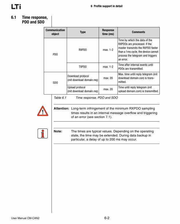
6 Profile support in detail
6.1 Time response, PDO and SDO
Attention: Long-term infringement of the minimum RXPDO sampling times results in an internal message overflow and triggering of an error (see section 7.1).
Note: The times are typical values. Depending on the operating state, the time may be extended. During data backup in particular, a delay of up to 200 ms may occur.
Communication object
TypeResponse time (ms)
Comments
PDO
RXPDO max. 1-2
Time by which the data of the RXPDOs are processed. If the master transmits the RXPDO faster than a 1ms cycle, the device cannot process the telegram and triggers an error.
TXPDO max. 1-2Time after internal events until PDOs are transmitted.
SDO
Download protocol(init download domain.req)
max. 20Max. time until reply telegram (init download domain.con) is trans-mitted.
Upload protocol(init download domain.req)
max. 20Time until reply telegram (init upload domain.com) is transmitted.
Table 6.1 Time response, PDO and SDO
6-2User Manual CM-CAN2

6 Profile support in detail
DEEN
1
2
3
4
5
6
7
A
6.2 DS301 boot-up The drive controller supports Minimum Capability Device behaviour in thenetwork. After power-up the drive controller enters the Pre-Operationalparameter-setting state. In this state the master can only communicatewith the drive controller via SDOs. The network status when the drivecontroller is parameterized appropriately has a direct influence on thesubsequent DRIVECOM state machine; that is to say, the device cannotbe enabled (i.e. the drive cannot be started) in the Pre-Operational state.
Note: Fundamentally, the PreOperational state is a parameter-setting state and the Operational state is an operating state.
Figure 6.1 Capability Device behaviour
In the Prepared state a CANopen slave can no longer participate incommunication via SDO or PDO. This state offers CANopen slaves thepossibility, in the event of serious errors, to opt out of the communicationprocess without disturbing the network.
6Start_Remote_Node indication
7Stop_Remote_Node indication
8Enter_Pre-Operational_State indication
10 Reset_Node indication
11Reset_Communication indication
12Initialization finished-enter Pre-Operational automatically
Initialisation
Pre-Operational
Operational
Controller enable onlypossible in Operational
Prepared6
6
7
7
8
101211
8
power on
User Manual CM-CAN2 6-3

6 Profile support in detail
Telegram structure of NMT services:
CS = Command Specifier
Figure 6.2 Telegram structure of NMT services.
Node ID = 00 h all slaves
6.2.1 Bus message after system start
After successful parameter setting of the device address and baud rate,the drive controller transmits a boot-up message over the CAN bus afterevery reset. This boot-up message has the same identifier as the emer-gency message, but contains no data.
dlc = data length code
No. in Figure 6.1 NMT serviceCommand Specifier
(CS in Figure 6.2)
6 Start_Remote_Node indication 01 h
7 Stop_Remote_Node indication 02 h
8 Enter_Pre-Operational_State indication 80 h
10 Reset_Node indication 81 h
11 Reset_Communication indication 82 h
Table 6.2 NMT services: Meaning of byte 0 in the NMT telegram
ID Byte 0 Byte 1
00H CS Node-ID
NMT - MASTER NMT - Slave
ID dlc
80 h + Node-ID 0
6-4User Manual CM-CAN2

6 Profile support in detail
DEEN
1
2
3
4
5
6
7
A
6.2.2 Influence of the DRIVECOM state machine on CANopen NMT
The network status of the CANopen module has a direct influence on thedevice's internal DRIVECOM state machine. Likewise, the internal statemachine can switch the network status to Pre-Operational in case oferror.
Figure 6.3 Influence of the DRIVECOM state machine on CANopen NMT
The two state machines communicate in the form of events. The influ-ence of the DRIVECOM state machine on the NMT status is relativelyeasy to explain:
If the NMT status is Operational when a device error occurs, theDRIVECOM state machine switches the device to Pre-Operational. Thisstate is only quit the next time the NMT command “Go operational” isdelivered.
Figure 6.4 CANopen NMT
DRIVECOM state DriveNMT state of
CANopen module
Preoperational
Operational
Event: Device errorDirection: DRIVECOM NMT
User Manual CM-CAN2 6-5

6 Profile support in detail
6.2.3 Influence of CANopen NMT on the DRIVECOMState machine
As already mentioned, it is possible to change DRIVECOM states bytransmitting a control word via RXPDO1. The transfer can logically onlybe executed in the NMT state: Operational. Additionally, the networkservices (see DS-301)
1. Start_Remote_Node and
2. Enter_Pre_Operational_State
trigger the following transitions dependent on the current DRIVECOMstatus:
a. In the Fault state a Start_Remote_Node telegram triggers resetting of an error.
Figure 6.5 Influence of CANopen NMT on the DRIVECOM state machine (a)
6
5
FAULT RESPONSEACTIVE
x0xx 1111
FAULT
x0xx 1000
0NOT
READY TO STARTx0xx 0000
0
SWITCH-ON INHIBIT
x1xx 0000 40H
14
1
2
Disable voltagexxxx xx0x x0H
Transition automatic approx. 4 sec. after power-up
1 Disable voltagexxxx xx0x12
Disable voltagexxxx xx0xEmergency stopxxxx x01x
10
9
Shutdownxxxx x110 x6H
13
*Start_Remote_Node
6-6User Manual CM-CAN2

6 Profile support in detail
DEEN
1
2
3
4
5
6
7
A
b. In the 4 OPERATION ENABLED state a Stop_Remote_Node tele-gram produces a transition to state 3 ON (control disabled). A subse-quent Start_Remot_Node automatically returns to state 4;
Figure 6.6 Influence of CANopen NMT on the DRIVECOM state machine (b)
All other DRIVECOM states are independent of the NMT status.
ON
x01x 0011 33H
OPERATION ENABLED
x1xx 0111 37H
3
4
5
6
3
4 7EMERGENCY STOP
ACTIVEx00x 0111 07H
Emergency stopxxxx x01x
Enable operationxxxx 1111 xFH
Shutdownxxxx x110 x6H
Disable operationxxxx 0111 x7H
Switch onxxxx x111 x7H
Start_Remote_Node
Stop_Remote_Node
User Manual CM-CAN2 6-7

6 Profile support in detail
6.3 Sync object The primary predefined CANopen communication object is the Syncobject. The Sync object enables the NMT master to synchronize theslaves in the network. When the PDO communication parameters areappropriately set, the Sync object can ensure, for example, that the refer-ence for the drive controller is accepted and the actual value is trans-mitted quasi simultaneously (see section 5.5).
Figure 6.7 Sync object
Telegram structure of the Sync object:
Figure 6.8 Telegram structure of the Sync object
Note: The sampling time of the CAN status can be determined by way of parameter 575-CASYC (see section 4.3.2).
Communication_Cycle_Period
synchronus window length
SYNCMessage Actual_
MessagesCommandMessages
SYNCMessage Actual_
MessagesCommandMessages
Samples taken at SYNCfor ACTUAL message
Actuation based onCOMMAND at next SYNC
ID Byte 0 - 7
80H No data
NMT - MASTER NMT - Slave
6-8User Manual CM-CAN2

6 Profile support in detail
DEEN
1
2
3
4
5
6
7
A
6.4 Emergency object
When an error occurs the drive controller transmits its errors in the formof an emergency message (profile DS-301) with an emergency error codedefined in DS-402. The error number of the drive controller is alsoentered in the manufacturer-specific data field.
ID = 80 h+ Node-ID
dlc data length code = 8
For further information on error handling, resetting of errors and themeanings of the error numbers refer to section 7.
Byte: 0 1 2 3 4 5 6 7
Bit: 0 ... 15 16 ... 23 24 ... 39 40 ... 47 48 ... 63
Profile Device Profile DS402 Drive controller
Content:
Emergency error code as per DS402
Error register (object 1001 h)
Error number Error locationOperating hours meter
(in full hours)
Table 6.3 Emergency object
User Manual CM-CAN2 6-9

6 Profile support in detail
6.5 Node Guarding To monitor the slaves the DS301 defines Node or Life guarding. Themaster polls the devices connected to the bus using a remote frame at adefined sampling time (guard time). In response to this polling, the slavetransmits a telegram containing the internal NMT status (Operational,Pre-Operational). This allows the master to check whether the slave statematches the master state.
Figure 6.9 Node Guarding
In contrast, the slave can only monitor the master by means of so-calledLife Guarding. If the master does not transmit a remote frame within thepreset lifetime, the slave (drive controller) must assume there is a fault inthe network and triggers a guarding error.
6.5.1 Monitoring by Node/Life Guarding
Two objects in the object directory are responsible for setting up Node/Life guarding.
By writing the object 100C h the NMT master can notify the slave of theso-called guard time. The Unsigned16 value of the object is given in ms.The guard time multiplied by the so-called life time factor (object 100D h)indicates the max. sampling time (life time) for the master and slave.
Node Guarding is started by the first remote telegram from the master.The drive controller replies by transmitting its NMT status and a toggle bit.
If the lifetime is exceeded the drive controller switches to error state (NMTstatus Pre-Operational) and transmits an emergency message with theerror location 91 Error Guarding CAN-Master.
Guard Time
Life Time
NMT Master NMT Master NMT Master NMT Master NMT Master
Slave Slave Slave Slave Slave
t
Draft 301 100C h VAR guard time Unsigned16 rw O
Draft 301 100D h VAR life time factor Unsigned16 rw O
6-10User Manual CM-CAN2

6 Profile support in detail
DEEN
1
2
3
4
5
6
7
A
Guarding is activated immediately on first receipt of the remote ID.
Data content / toggle bit:
6.6 Default setting of communica-tion objects
The settings of the standardized objects of the CANopen profile (COB IDof emergency, SYNC, transmission types of PDOs etc.) correspond to aso-called Predefined Connection Set. This a preconfiguration intended toprovide the user with a fast commissioning process. The following tableshows the delivery condition ex factory:
COB identifier
CANopen status Remote ID Data content
Pre-Operational 700 h + Node ID7F h
|FF h
Alternating
operational 700 h + Node ID05 h
|85 h
Alternating
Table 6.4 Monitoring by Node/Life Guarding
Object Function code COB IDCommunication parameter
from index
NMT 0000 0 0 h -
Sync 0001 128 80 h 1005 h
Emergency 0001 129-255 81-FF h -
PDO1(tx) 0011 385-511 181-1FF h 1800 h
PDO1(rx) 0100 513-639 201-27F h 1400 h
SDO(tx) 1011 1409-1535 581-5FF h -
SDO(rx) 1100 1537-1663 601-1FF h -
Node Guard 1110 1793-1919 701-1FF h 100E h
Table 6.5 Default setting of communication objects
Bit no.
Function code Module-ID= COB-ID
10 9 8 7 6 5 4 3 2 1 0
User Manual CM-CAN2 6-11

6 Profile support in detail
6.7 Object direc-tory DS-301/DS-402
The central instance of all CANopen nodes, like in other field bus proto-cols, is the so-called object directory. Each CANopen device must knowthe so-called object directory. In this directory, in addition to the standard-ized entries the objects relevant to the device must also be accessible.
The following table gives an overview of the profile support of the drivecontroller:
Profile Index Object Name Type Acc. M/O
Draft 301 1000 h VAR device type Unsigned32 ro M
Draft 301 1001 h VAR error register Unsigned8 ro M
Draft 301 1003 h ARRAY predefined error field Unsigned32 ro O
Draft 301 1004 h ARRAY number of PDOs supported Unsigned32 ro O
Draft 301 1005 h VAR COB-ID Sync message Unsigned32 rw O
Draft 301 1006 h VAR communication cycle period Unsigned32 rw O
Draft 301 1007 h VAR synchronous window length Unsigned32 rw O
Draft 301 1008 h 1) VAR manufacturer device name Vis-String ro O
Draft 301 100A h 3) VAR manufacturer software version Vis-String ro O
Draft 301 100B h VAR node-ID Unsigned32 ro O
Draft 301 100C h VAR guard time Unsigned32 rw O
Draft 301 100D h VAR life time factor Unsigned32 rw O
Draft 301 100E h VAR node-guarding identifier Unsigned32 rw O
Draft 301 100F h VAR number of SDOs supported Unsigned32 ro O
Draft 301 1010 h ARRAY store parameters Unsigned32 rw O
Draft 301 1011 h VAR restore default parameters Unsigned32 rw O
Draft 301 1014 h VAR COB-ID emergency message Unsigned32 rw O
Draft 301 1018 h RECORD Vendor-ID Unsigned32 ro M
Draft 301 1200 h RECORD server SDO Parameter SDO-Parameter rw O
Draft 301 1400 h RECORD receive PDO comm.parameter PDOCommPar rw O
Draft 301 1600 h ARRAY receive PDO mapping parameter PDOMapping rw O
Draft 301 1800 h RECORD transmit PDO comm-parameter PDOCommPar rw O
Draft 301 1A00 h ARRAY transmit PDO mapping-parameter PDOMapping rw O
manufacturer specific
2000 h-
23E8 hinverter parameter
Draft 402 6040 h 4) VAR controlword integer16 rw M
Draft 402 6041 h 5) VAR statusword Unsigned16 ro M
Table 6.6 Object directory DS-301/DS-402
6-12User Manual CM-CAN2

6 Profile support in detail
DEEN
1
2
3
4
5
6
7
A
Note: For more information on the object directory and on creating an EDS file refer to section 6.9.
Draft 402 6060 h 6) VAR modes_of_operation integer8 wo M
Draft 402 6061 h 7) VAR modes_of_operation_display integer8 ro M
1) Content same as device parameter 390-TYPE3) Content same as device parameter 92-REV4) Content same as device parameter 573_CACTR5) Content same as device parameter 572-CASTA6) Content same as device parameter 152-ASTER7) Content same as device parameter 152-ASTER
M = MandatoryO = Optional
Profile Index Object Name Type Acc. M/O
Table 6.6 Object directory DS-301/DS-402
User Manual CM-CAN2 6-13

6 Profile support in detail
6.8 Default setting of DS301/402 objects
IndexSub-index
Read value IndexSub-index
Read value
1000 00 0x0192 1600 00 0x02
1001 00 0x00 01 0x21eb0010 (491)
1003 00 0x01 02 0x21f10020 (497)
01 0x00
1004 00 0x00030002 1800 00 0x04
01 0x00000000 01 0x182
02 0x00030002 02 0xa
1005 00 - 03 0x4
1006 00 0x00000000 04 0x4
1007 00 0x00000000
1008 00 Device type 1A00 00 0x2
100A 00Current software version of device
01 0x21ea0010
100B 00 0x02 (at addr.2) 02 0x21900020
100C 00 - 1A01 00 0x01
100D 00 - 01 0x22490008
100E 00 0x702 (at addr. 2)
100F 00 0x01 6040 00 -
1014 00 0x40000082 6041 00 -
1018 00 0x16 6060 00 -
6061 00
1400 00 0x04
01 0x202
02 0xFE
03 0x00
04 0x01
Table 6.7 Default setting of DS301/402 objects
6-14User Manual CM-CAN2

6 Profile support in detail
DEEN
1
2
3
4
5
6
7
A
6.9 EDS device file DS-301 defines the content of a so-called EDS (Electronic Data Sheet)file. This text file contains all device-specific data and parameters in termsof their data type, value range and access attributes. A number of setuptools for CANopen networks use this file for graphical visualization of theindividual CANopen nodes.
6.9.1 How do I create the EDS device file?
The DRIVEMANAGER setup tool has a secondary menu, Create EDS File,under its Tools menu. Then you can in turn choose whether to create theEDS file from an existing device database stored on hard disk or floppy(parameter set) or the currently connected device. You can then copy thenewly created EDS file to the relevant directory of your CANopen setuptool.
6.10 Saving the CANopen settings
The user-specific settings made in the object directory (objects 1000 h to1A00 h) can be stored permanently and are then available every time thedevice starts up.
The object 1010 h with subindex 0x02 delivers this functionality.
To prevent unwanted settings from being saved accidentally, the saveoperation is triggered by a defined code.
Save code 0x65766173
The save operation can be triggered by the following SDO access:
Note: The save operation disables the drive controller's communi-cation capability for approx. 0.5 seconds, which means with guarding active the master would not detect an error.
Draft 301 1010 h ARRAY store parameters Unsigned32 rw O
SDO transfer mode Index Subindex Value
- write 1010 h 02 h 0x65766173
ID Data bytes Description
SDO(rx) 23 10 10 02 73 61 76 65 Download protocol (write)Master >drive controller
SDO(tx) 60 10 10 00 00 00 00 00 Drive controller> master
User Manual CM-CAN2 6-15

6 Profile support in detail
6.11 Restoring factory defaults
The factory setup (Predefined Connection Set) of the communicationsettings mentioned above can be restored by SDO write access to object1011 h.
Here, too, a save code is used for safety.
Save code 0x64616f6c
The factory defaults can be restored by the following SDO access:
Note: The save operation disables the drive controller's communi-cation capability for approx. 0.5 seconds, which means with guarding active the master would not detect an error.
Draft 301 1011 h ARRAY restore default parameters Unsigned32 rw O
SDO transfer mode Index Subindex Value
- write 1011 h 02 h 0x64616f6c
ID Data bytes Description
SDO(rx) 23 11 10 02 6c 6f 61 64;Download protocol (write)Master >drive controller
SDO(tx) 60 11 10 00 00 00 00 00 ;Drive controller> master
6-16User Manual CM-CAN2

DEEN
1
2
3
4
5
6
7
A
7 Error rectification
7.1 Troubleshooting ......................................................7-1
7.2 Resetting an error ...................................................7-37.2.1 Error acknowledgment via bus system .................7-37.2.2 Error acknowledgment, general ...........................7-3
7.3 Emergency error codes table ..................................7-77.3.1 Standard error messages of the CDA3000 ...........7-77.3.2 Description of communication errors ....................7-8
7.1 Troubleshooting All errors detected by the inverter are transmitted once over the CAN busin the form of an emergency message. They are signaled by flashing ofthe red LED H1 on the inverter.
ID = 80 h+ Node-ID
dlc data length code = 8
Byte: 0 1 2 3 4 5 6 7
Bit: 0 ... 15 16 ... 23 24 ... 39 40 ... 47 48 ... 63
Profile Device Profile DS402 Drive controller
ErrorEmergency error code as
per DS402Error register
(object 1001 h)Error number Error location
Operating hours meter(in full hours)
Warning (CDA3000 only)
00 h FF h 01 h FF hWarning Low Byte
WarningHigh Byte
Table 7.1 Emergency codes
User Manual CM-CAN2 7-1

7 Error rectification
The decisive factors for rapid localization are the error code and errorlocation. In bytes 3 and 4 of the emergency telegram you will find theerror code, which represents a first categorization of the cause of theerror (see Table 7.1). The precise cause of the error is specified by theerror location in byte 5. Bytes 6 and 7 contain the internal operating hoursmeter of the device (parameter 87-TOP).
CANopen errors - i.e. incorrect configurations, bus disturbances etc. - areindicated by error code 0xFF00.
Note: When an error occurs, the inverter automatically switches to the Pre-Operational state. The active drive is stopped by an emergency stop, the DRIVECOM state machine switches to Ready. In case of error shutdown the power stage is gener-ally shut off, i.e. braking functions such as ramping or DC braking are not executed!
Note: The LED status indicators are explained in section 2.3.2.
7-2User Manual CM-CAN2

7 Error rectification
DEEN
1
2
3
4
5
6
7
A
7.2 Resetting an error
The drive controller offers several different ways of resetting an error.
7.2.1 Error acknowl-edgment via bus system
By the transition from the Pre-Operational to the Operational state anycurrent errors are reset. Resetting of the error is signaled by transmissionof the following emergency message:
xx xx Operating hours meter
If the cause of the error is not eliminated, the drive controller returns tothe Pre-Operational NMT state after transmission of another emergencymessage.
Another possibility is offered by the object 6040 h control word:
The error is also reset by setting object 6040 h to the value 0x0080 (SDOdownload protocol, since PDO transfer only possible in the Operationalstate).
7.2.2 Error acknowl-edgment, general
• by a rising signal edge at the control input ENPO
• by a rising edge at a programmable digital input with setting of the function selector to ERES
• by writing the value 1 to parameter 74-ERES by way of the control unit or bus system
ID Data bytes ;Description
Emergency 00 00 00 00 00 00 xx xx ;Emergency message acknowledgment error
Draft 402 6040 h VAR controlword Integer16 rw M
User Manual CM-CAN2 7-3

7 Error rectification
Overview of all CDA3000 error messages
Error no. Error Description
1 E-CPU Hardware or software error
2 OFF Power failure
3 E-OC Current overload shut-off
4 E-OV Voltage overload shut-off
5 E-OLI IxIxt shut-off
6 E-OLM Ixt shut-off
7 E-OTM Motor overheating
8 E-OTI Drive unit overheating
9 E-PLS Plausibility error in parameter or program sequence
10 E-PAR Faulty parameter setting
11 E-FLT Floating point error
12 E-PWR Power pack not recognized
13 E-EXT External error message (input)
14 E-USR Reserved for modified software
15 E-OP1 Error in module in option slot 1
16 E-OP2 Error in module in option slot 2
17 - -
18 E-SIO Error in serial interface
19 E-EEP Faulty EEPROM
20 E-WBK Wire break
21 E-SC Auto-tuning
22 E-PF Power failure
23 E-RM Encoder evaluation defective
24 E-FDG Transmission error in reference coupling
25 E-LSW Limit switches reversed
26 E-OL5 lxt shut-off below 5 Hz to protect power stage
Table 7.2 Error message in the CDA3000
7-4User Manual CM-CAN2

7 Error rectification
DEEN
1
2
3
4
5
6
7
A
Overview of all CDD3000 error messages
Error no. Error Description
1 E-CPU Hardware or software error
2 OFF Power failure
3 E-OC Current overload shut-off
4 E-OV Voltage overload shut-off
5 E-OLI IxIxt shut-off
6 E-OLM Ixt shut-off
7 E-OTM Motor overheating
8 E-OTI Drive unit overheating
9 E-PLS Plausibility error in parameter or program sequence
10 E-PAR Faulty parameter setting
11 E-FLT Floating point error
12 E-PWR Power pack not recognized
13 E-EXT External error message (input)
14 E-USR Reserved for modified software
15 E-OP1 Error in module in option slot 1
16 E-OP2 Error in module in option slot 2
17 - -
18 E-SIO Error in serial interface
19 E-EEP Faulty EEPROM
20 E-WBK -
21 E-SC -
22 E-PF -
23 E-RM -
24 E-FDG -
25 E-LSW D-HWE/limit switches interchanged
26 E-OL5 lxt shut-off below 5 Hz to protect power stage
30 E-ENC Error in encoder monitoring
31 E-TIM Runtime monitoring
32 E-FLW Tracking error
33 E-WDG Watchdog RS232
34 E-VEC Internal memory error
Table 7.3 CDD3000 error messages
User Manual CM-CAN2 7-5

7 Error rectification
Note: For a detailed list of all error messages together with reme-dial measures refer to the relevant Application Manual.
35EBRK Error at output OSD03:
1.Wire break 2. Short 3. Overload
36 E-POS 210: Positive hardware limit switch approached211: Negative hardware limit switch approached212: Positive software limit switch approached213: Negative software limit switch approached214: Reference point not defined215: Error accessing optional hardware Possible remedies: If this error is repeated please contact your local Service Partner.
216: Selected program not available217: Jump to non-existent record number218: Called subroutine not available219: Target position outside positioning range220: Division by zero
221: Max. subroutine nesting depth exceeded222: Timeout in manual mode223: Target position not reached224: No feed hold225: Selection (Automatic/Referencing/Jog mode) not
permitted, control location conflict226: Index overflow (indexed addressing)
230: Max. servo speed exceeded232: No controller enable (ENPO)233: Error in parameter access of position and sequence
controlPossible remedies: If this error is repeated please contact your local Service Partner.234: Error processing a Touchprobe positioning
command235: Impermissible command during axle movement236: Hardware limit switches interchanged
37 E-FLH Error in flash memory
38 E-HW Hardware limit switch approached
39 E-HWE Hardware limit switches interchanged
40E-WRN The preset maximum torque (parameter TCMMX) is greater than
\n the maximum torque attainable with the motor or the device
Error no. Error Description
Table 7.3 CDD3000 error messages
7-6User Manual CM-CAN2

7 Error rectification
DEEN
1
2
3
4
5
6
7
A
7.3 Emergency error codes table
7.3.1 Standard error messages of the CDA3000
For the error messages of the CDA3000 refer to the “Warning messages”and “Error messages” sections of the Application Manual.
Error textError no.
(dec.)Emergency error
codeError register Description
NoError 0 0x0000 1/generic error Error acknowledgment
E-CPU 1 0x5220 1/generic error Hardware or software error
E-OFF 2 0x3100 1/generic error Power failure
E-OC / OverCurrent 3 0x2340 1/generic error Current overload shut-off
E-OV /OverVoltage 4 0x3110 1/generic error Voltage overload shut-off
E-OLM/ Ixt 5 0x2310 1/generic error Ixt shut-off
E-OLI / IxIxt 6 0xff00 1/generic error I²xt shut-off
E-OTM / OverTemperatureMotor 7 0x4300 1/generic error Motor overheating
E-OTI / OverTemperatureInverter 8 0x4200 1/generic error CDA overheating
E-PLS / DataPlausibility 9 0x6100 1/generic error Faulty EEPROM
E-PAR /ParameterValue 10 0x6320 1/generic error Faulty parameter setting
E-FLT / Float 11 0x6100 1/generic error Floating point error
E-PWR / NoPowerModule 12 0x5400 1/generic error Power pack not recognized
E-EXT / External 13 0x9000 1/generic error External error message
E-USR 14 0x6200 1/generic error Modified software
E-OP1 /Option1 15 0x7000 1/generic error Module in Option1
E-OP2 /Option2 16 0x7000 1/generic error Module in Option2
E-SIO / WatchDog 18 0x7510 1/generic error Watchdog
E-FLH / Flash 19 0x5530 1/generic error Error in FLASH memory
E-WBK / Wire break 20 0x5440 1/generic error Encoder evaluation defective
E-SC / Auto-tuning 21 0xff00 1/generic error
E-PF / PowerFail 22 0x5400 1/generic error Power failure
E-RM / InitRunMode 23 0xff00 1/generic error Encoder evaluation defective
E-FDG 24 0xff00 1/generic error Reference coupling
E-LSW 25 0x8612 1/generic error Limit switches swapped
255 0xFF00 1/generic error Warning
Table 7.4 Assignment of emergency error codes
User Manual CM-CAN2 7-7

7 Error rectification
7.3.2 Description of communication errors
Bus DM/KPError
location no.
Error cause Possible remedyRespon-
seno.
16 E-OP2 170 Error in module at option slot 2 Check module and identifier STOP *
171Error at option slot 2: BUS-OFF state detected.
Check contacting of module. If the error still occurs after switching off and back on again, the device or the module is faulty.
172
Error at option slot 2: Transmit protocol could not be sent.
Check contacting of module and master func-tion. If the error still occurs after switching off and back on again, the device or the module is faulty.
173Error at option slot 2: Module not respond-ing.
Check contacting of module. If the error still occurs after switching off and back on again, the device or the module is faulty.
* The error response is programmable (see Application Manual). The factory set default response is STOP, i.e. disable power stage.
Table 7.5 CDA3000 errors
Error textError location
number at option slot 2
Emergency error code
Error register Description of error
E-OP2 180 0xFF00 0x07 EEprom write error
E-OP2 181 0xFF00 0x07 EEprom read error
E-OP2 182 0xFF00 0x07 Initialization error
E-OP2 183 0x8100 0x11 CDA <>module communication error
E-OP2 184 0x8100 0x11 Bus-Off CANopen network
E-OP2 185 0x8100 0x11 Error counter overflow
E-OP2 186 0x8100 0x11 Node Guarding error
E-OP2 187 0x8100 0x11 RX-QUEUE overflow
Table 7.6 Communication errors
7-8User Manual CM-CAN2

DEEN
1
2
3
4
5
6
7
A
Appendix Glossary
CiA: (“CAN in Automation”). CAN bus user group, generally defines a protocol for automation.
CAL: (CAN Application Layer) CiA protocol, primarily describes the way in which variables are transmitted without defining their function or content.
Subsets:
CMC:(CAN based Message Specification). Sets out the definition described above. Is accepted by most CAN suppliers. LUST conforms to this definition.
NMT: (Network Management). Required for masters in the CAN system. Not implemented by Lust because drive controllers are always slaves and have no “control function”.
LMT: (Layer Management). See NMT
DBT:(Identifier Distributor). See NMT
CANopen: Based on CAL definition
Corresponds to CiA Draft Standard 301
Expands the CAL definition to include function and unit assignment of the predefined variables
This definition is being drafted by CiA and various user groups (MOTION for drive technology and I/O for inputs/outputs) (e.g. variable for torque in Nm).
User Manual CM-CAN2 A-1

Appendix
General points on the various protocol definitions
Motion: User group under CiA tasked to draft a profile of the CANopen protocol for drive technology.
I/O: User group under CiA tasked to draft a profile of the CANopen protocol for sensors and actuators.
CAL: Mainly in use in Europe.
LUST has currently implemented a protocol which can be activated by a CAL master.
The initialization is simpler than CAL (CCDA), for example addressing by way of jumper, which has no influence on operation.
DeviceNet: Mainly in the USA (corresponds to CAL definition).
SDS: Has not established itself.
A-2User Manual CM-CAN2

1
Appendix IndexDEEN
2
3
4
5
6
7
A
AAddress parameter ............................... 2-2Assignment of emergency error codes .......... 7-7
BBack-up device setup ............................ 4-15Baud rate ......................................... 4-11Boot-up message ................................. 3-5Bus message after system start ................. 6-4
CCAN bus connection specification ................ 2-8CANopen device address, parameter ........... 4-10CANopen, Introduction ............................ 1-3CDA3000 configuration ........................... 4-5Coding switches .................................. 2-3Commissioning .................................... 3-2Communication errors ............................ 7-8Configuration ...................................... 3-2Connector coding ................................. 2-2Connectors X11 and X12 ......................... 2-2Control functions .................................. 5-5Control location, parameter ..................... 4-12Control word, parameter ......................... 4-14Controller enable ENPO ........................... 2-8
DDangers ........................................... 1-2Data backup ...................................... 4-15Data handling ..................................... 3-6Default setting of DS301/402 objects ........... 6-14Device parameters, where can I find the ... .... 4-15Downloading parameter data sets .............. 4-18DRIVECOM state machine
Influence on CANopen NMT .................. 6-5DS301 boot-up .................................... 6-3
EEasyDrive control mode ......................... 5-15EDS device file ................................... 6-15EMC (Electromagnetic Compatibility) ............ 1-2Emergency codes ................................. 7-1Emergency error codes table ..................... 7-7Emergency object ................................. 6-9Error acknowledgment ........................... 7-3Error acknowledgment via bus system .......... 7-3Error rectification ................................. 7-1
FFurther documentation ........................... 1-4
HHardware enable ENPO ........................... 2-8
IInitialization, error ................................. 3-5Installation ......................................... 2-7
LLED status display ................................ 2-9
MMonitoring by Node/Life Guarding .............. 6-10Mounting .................................... 2-1, 2-4
with size BG1...5 ............................. 2-5with size BG6...8 ............................. 2-6
Mounting package MP-UMCM ................... 2-6
NNode Guarding ................................... 6-10Node ID ............................................ 6-4
User Manual CM-CAN2 A-3

Appendix Index
PParameter channel ................................ 4-2Parameter setting ................................. 4-1Parameters, CDA3000 for bus operation ......... 4-7Pictograms ......................................... 1-4
QQualification, users ................................ 1-2
RReference selector, parameter ................. 4-12Reference selector, settings .................... 4-13Reference source ................................ 4-13Reference via RXPDO1, parameter ............. 4-14Resetting an error ................................. 7-3Restoring factory defaults ................. 3-6, 6-16
SSafety precautions ................................ 1-2Sampling time, status message, parameter ... 4-11Saving settings .................................... 3-6Saving the CANopen settings ................... 6-15SDO data transfer (example) ...................... 4-2SDO handling .................................... 4-15Setting the address ................................ 2-2Settings for reference selector .................. 4-13Size (BG1...5) ...................................... 2-4Size (BG6...8) ...................................... 2-6Standard error messages of the CDA3000 ....... 7-7Status messages ................................ 5-11Status word, parameter ......................... 4-14String parameter, example ...................... 4-16Sync object ........................................ 6-8System connection diagram ...................... 2-7System requirements ............................. 1-4
TTelegram structure of NMT services ............. 6-4Telegram structure of the Sync object ........... 6-8Transmission speeds ............................ 2-10Troubleshooting ................................... 7-1
User Manual CM-CAN2 A-4


LTi DRiVES GmbHGewerbestr. 5-935633 LahnauGERMANYFon: +49 (0) 64 41 / 96 6-0Fax: +49 (0) 64 41 / 9 66-1 37
ID no.: 0916.02B.2-00 • Date: 01/2014
We reserve the right to make technical changes.
The content of our documentation was compiled with the greatestcare and attention, and based on the latest information available tous.
We should nevertheless point out that this document cannot alwaysbe updated in line with ongoing technical developments in our pro-ducts.
Information and specifications may be subject to change at any time.