konica finisher fs-105 parts and service manual
TRANSCRIPT
SERVICE MANUAL
MODEL
FS-105
JUNE 1998
CSM-FS105
iii
CONTENTS
TABLE OF CONTENTSSAFETY PRECAUTIONS........................................................ v
FS-105SPECIFICATIONS ................................................................. 1
Type ............................................................................... 1Functions ....................................................................... 1Stapler Kit ...................................................................... 1Machine Data ................................................................. 1Maintenance .................................................................. 1Operating Environment ................................................. 1
CENTER CROSS SECTION ................................................. 3DRIVE SYSTEM DIAGRAM .................................................... 4
Paper Conveyance System Drive .................................. 4Stapler Unit Drive ........................................................... 4
EXTERNAL SECTION ........................................................... 5Construction .................................................................. 5Disassembly and Reassembly .................................... 5
CONVEYANCE SECTION ..................................................... 8Construction .................................................................. 8Mechanisms .................................................................. 8Disassembly and Reassembly .................................. 11Paper Feed Motor (M801) Control ............................... 13Conveyance Drum (M807) Control .............................. 14Tray Up/Down (M804) Control ..................................... 15
PAPER EXIT/STAPLER UNIT SECTION ............................. 16Construction ................................................................ 16Mechanisms ................................................................ 16Disassembly and Reassembly .................................. 18Paper Alignment Control ............................................. 20Paper Exit (M805) Control ............................................ 21Paper Stacking Control ............................................... 22Stapler Movement (M806) Control ............................... 24Stapler Control ............................................................. 25
OTHER CONTROL FUNCTIONS ....................................... 27Power On Operation .................................................... 27
DIAGRAMSELECTRICAL PARTS LAYOUT DIAGRAM .......................... 28CONNECTOR LAYOUT DIAGRAM...................................... 29

iv
This page left blank intentionally.
1
FS-105
PRODUCT SPECIFICATIONS
Mode
Through mode
Through mode
Offset mode
Staple mode
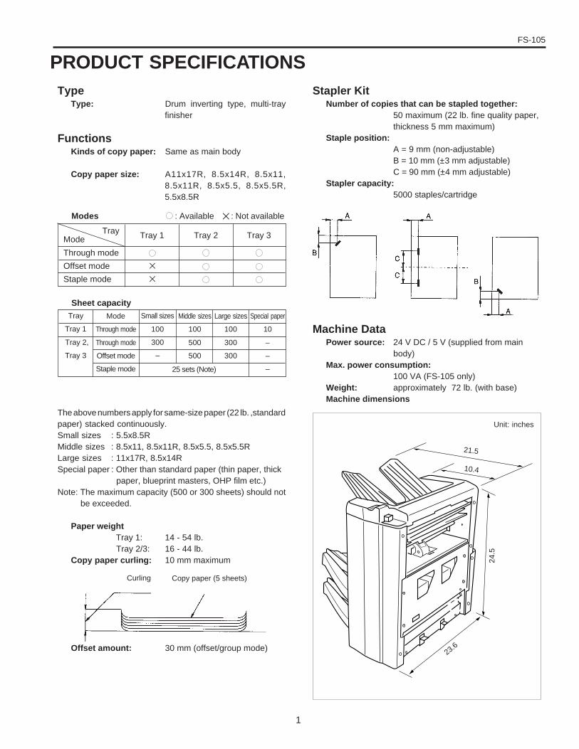
TypeType: Drum inverting type, multi-tray
finisher
FunctionsKinds of copy paper: Same as main body
Copy paper size: A11x17R, 8.5x14R, 8.5x11,8.5x11R, 8.5x5.5, 8.5x5.5R,5.5x8.5R
The above numbers apply for same-size paper (22 lb. ,standardpaper) stacked continuously.Small sizes : 5.5x8.5RMiddle sizes : 8.5x11, 8.5x11R, 8.5x5.5, 8.5x5.5RLarge sizes : 11x17R, 8.5x14RSpecial paper : Other than standard paper (thin paper, thick
paper, blueprint masters, OHP film etc.)Note: The maximum capacity (500 or 300 sheets) should not
be exceeded.
Paper weight Tray 1: 14 - 54 lb. Tray 2/3: 16 - 44 lb.Copy paper curling: 10 mm maximum
Offset amount: 30 mm (offset/group mode)
Sheet capacity
Mode
Through mode
Offset mode
Staple mode
Tray Tray 3Tray 2
Large sizes
100
300
300
Tray
Tray 1
Tray 2,
Tray 3
Special paper
10
–
–
–
Small sizes
100
300
–
Middle sizes
100
500
500
Tray 1
✕
✕
Modes : Available ✕ : Not available
Stapler KitNumber of copies that can be stapled together:
50 maximum (22 lb. fine quality paper,thickness 5 mm maximum)
Staple position:A = 9 mm (non-adjustable)B = 10 mm (±3 mm adjustable)C = 90 mm (±4 mm adjustable)
Stapler capacity:5000 staples/cartridge
Machine DataPower source: 24 V DC / 5 V (supplied from main
body)Max. power consumption:
100 VA (FS-105 only)Weight: approximately 72 lb. (with base)Machine dimensions
21.5
10.4
24.5
23.6
25 sets (Note)
Curling Copy paper (5 sheets)
Unit: inches

FS-105
2
MaintenanceMaintenance: Same as main body
Operating EnvironmentTemperature: 50°F ~ 91°FHumidity: 20% to 80% RH
Note: The contents of this manual may be changed withoutprior notice.
3
FS-105
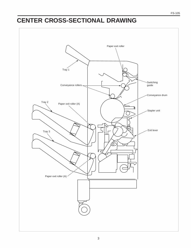
CENTER CROSS-SECTIONAL DRAWING
Conveyance drum
Stapler unit
Exit lever
Conveyance rollers
Paper exit roller (A)
Tray 3
Tray 2
Switchingguide
Paper exit roller
Tray 1
Paper exit roller (A)
FS-105
4
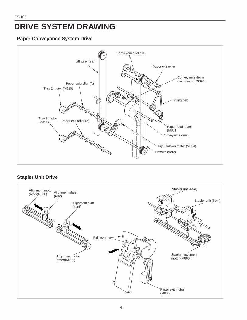
DRIVE SYSTEM DRAWINGPaper Conveyance System Drive
Stapler Unit Drive
Paper exit roller (A)
Lift wire (rear)
Conveyance rollers
Tray 2 motor (M810)
Paper exit roller (A)Tray 3 motor(M811)
Paper exit roller
Conveyance drumdrive motor (M807)
Timing belt
Conveyance drum
Paper feed motor(M801)
Tray up/down motor (M804)
Lift wire (front)
Stapler movementmotor (M806)
Stapler unit (front)
Stapler unit (rear)
Alignment motor(front)(M809)
Alignment plate(front)
Alignment plate(rear)
Alignment motor(rear)(M808)
Exit lever
Paper exit motor(M805)
5
FS-105
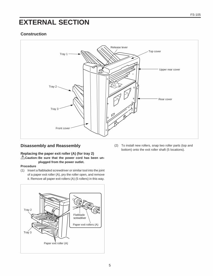
EXTERNAL SECTION
Construction
(2) To install new rollers, snap two roller parts (top andbottom) onto the exit roller shaft (5 locations).
Rear cover
Upper rear cover
Disassembly and Reassembly
Replacing the paper exit roller (A) (for tray 2)Caution: Be sure that the power cord has been un-
plugged from the power outlet.Procedure(1) Insert a flatbladed screwdriver or similar tool into the joint
of a paper exit roller (A), pry the roller open, and removeit. Remove all paper exit rollers (A) (5 rollers) in this way.
Tray 1
Tray 2
Tray 3
Front cover
Top cover Release lever
Paper exit roller (A)
Tray 2
Tray 3
Flatbladescrewdriver
Paper exit rollers (A)
FS-105
6
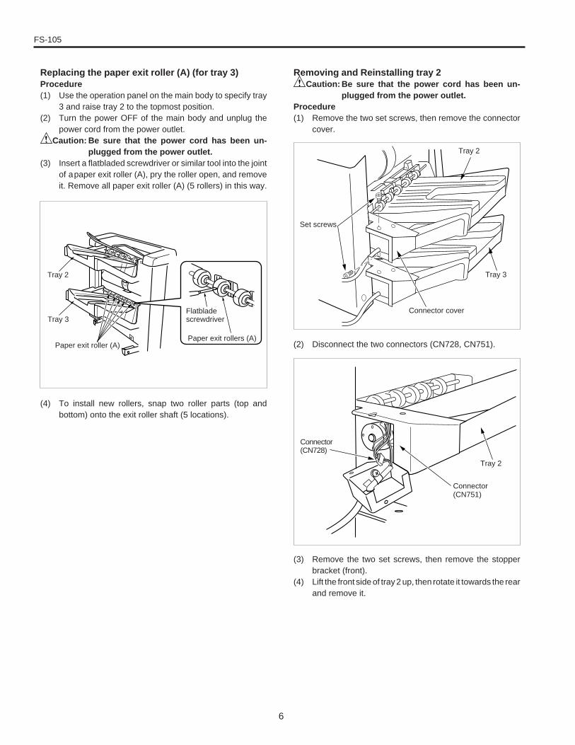
Replacing the paper exit roller (A) (for tray 3)Procedure(1) Use the operation panel on the main body to specify tray
3 and raise tray 2 to the topmost position.(2) Turn the power OFF of the main body and unplug the
power cord from the power outlet.Caution: Be sure that the power cord has been un-
plugged from the power outlet.(3) Insert a flatbladed screwdriver or similar tool into the joint
of apaper exit roller (A), pry the roller open, and removeit. Remove all paper exit roller (A) (5 rollers) in this way.
Removing and Reinstalling tray 2Caution: Be sure that the power cord has been un-
plugged from the power outlet.Procedure(1) Remove the two set screws, then remove the connector
cover.
(2) Disconnect the two connectors (CN728, CN751).
(3) Remove the two set screws, then remove the stopperbracket (front).
(4) Lift the front side of tray 2 up, then rotate it towards the rearand remove it.
Connector cover
Set screws
Tray 2
Tray 3
Tray 2
Connector(CN751)
Connector(CN728)
(4) To install new rollers, snap two roller parts (top andbottom) onto the exit roller shaft (5 locations).
Tray 2
Tray 3Flatbladescrewdriver
Paper exit rollers (A)Paper exit roller (A)
7
FS-105
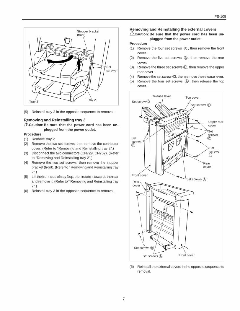
(5) Reinstall tray 2 in the opposite sequence to removal.
Removing and Reinstalling tray 3Caution: Be sure that the power cord has been un-
plugged from the power outlet.Procedure(1) Remove tray 2.(2) Remove the two set screws, then remove the connector
cover. (Refer to “Removing and Reinstalling tray 2”.)(3) Disconnect the two connectors (CN729, CN752). (Refer
to “Removing and Reinstalling tray 2”.)(4) Remove the two set screws, then remove the stopper
bracket (front). (Refer to “ Removing and Reinstalling tray2”.)
(5) Lift the front side of tray 3 up, then rotate it towards the rearand remove it. (Refer to “ Removing and Reinstalling tray2”.)
(6) Reinstall tray 3 in the opposite sequence to removal.
Removing and Reinstalling the external coversCaution: Be sure that the power cord has been un-
plugged from the power outlet.Procedure(1) Remove the four set screws A , then remove the front
cover.(2) Remove the five set screws B , then remove the rear
cover.(3) Remove the three set screws C , then remove the upper
rear cover.(4) Remove the set screw D , then remove the release lever.(5) Remove the four set screws E , then release the top
cover.
Tray 2
Setscrews
Stopper bracket(front)
Tray 3
Set screws A
Set screws B
Front cover
Set screws A
Rearcover
SetscrewsB
SetscrewsC
Set screws E
Top coverRelease lever
Set screw D
Front cover
Upper rearcover
Setscrews E
Rearcover
(6) Reinstall the external covers in the opposite sequence toremoval.
FS-105
8
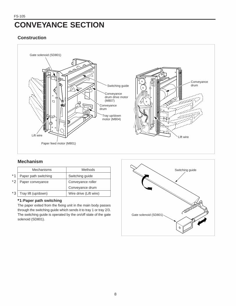
CONVEYANCE SECTION
Construction
Mechanism
∗∗∗∗∗1:Paper path switchingThe paper exited from the fixing unit in the main body passesthrough the switching guide which sends it to tray 1 or tray 2/3.The switching guide is operated by the on/off state of the gatesolenoid (SD801).
Gate solenoid (SD801)
Switching guide
Conveyancedrum drive motor(M807)
Conveyancedrum
Tray up/downmotor (M804)
Paper feed motor (M801)
Lift wire
Conveyancedrum
Lift wire
Switching guide
Gate solenoid (SD801)
Mechanisms
Paper path switching
Paper conveyance
Tray lift (up/down)
Methods
Switching guide
Conveyance roller
Conveyance drum
Wire drive (Lift wire)
∗1
∗2
∗3
9
FS-105
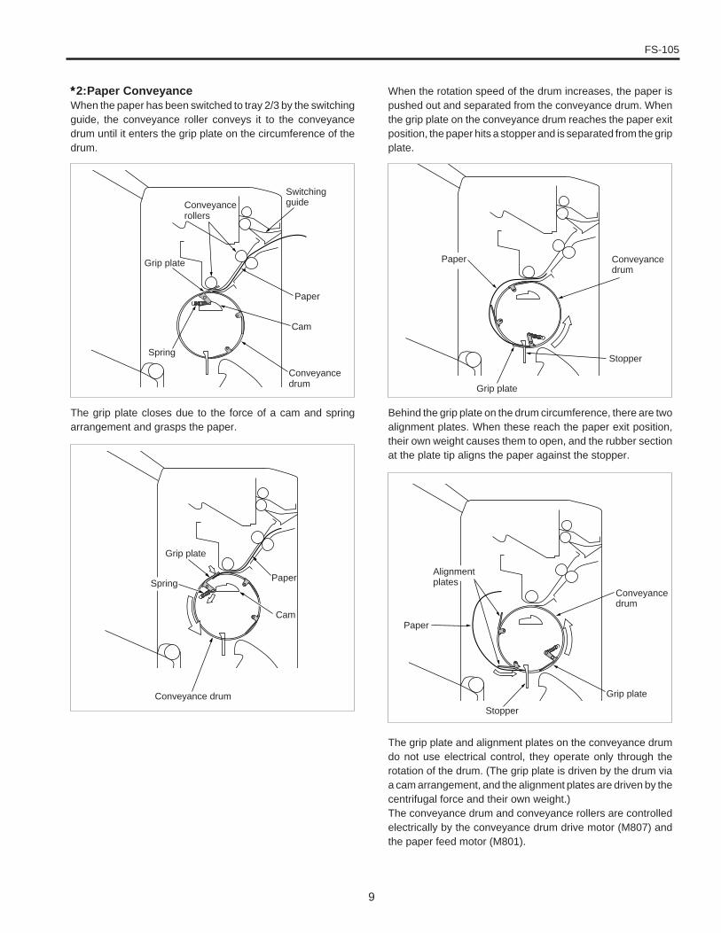
∗∗∗∗∗2:Paper ConveyanceWhen the paper has been switched to tray 2/3 by the switchingguide, the conveyance roller conveys it to the conveyancedrum until it enters the grip plate on the circumference of thedrum.
The grip plate closes due to the force of a cam and springarrangement and grasps the paper.
When the rotation speed of the drum increases, the paper ispushed out and separated from the conveyance drum. Whenthe grip plate on the conveyance drum reaches the paper exitposition, the paper hits a stopper and is separated from the gripplate.
Behind the grip plate on the drum circumference, there are twoalignment plates. When these reach the paper exit position,their own weight causes them to open, and the rubber sectionat the plate tip aligns the paper against the stopper.
Conveyancerollers
Paper
Cam
Conveyancedrum
Grip plate
Spring
Switchingguide
Cam
Grip plate
Conveyance drum Grip plate
Stopper
Paper
Alignmentplates
Conveyancedrum
Conveyancedrum
Grip plate
The grip plate and alignment plates on the conveyance drumdo not use electrical control, they operate only through therotation of the drum. (The grip plate is driven by the drum viaa cam arrangement, and the alignment plates are driven by thecentrifugal force and their own weight.)The conveyance drum and conveyance rollers are controlledelectrically by the conveyance drum drive motor (M807) andthe paper feed motor (M801).
Paper
Stopper
SpringPaper
FS-105
10
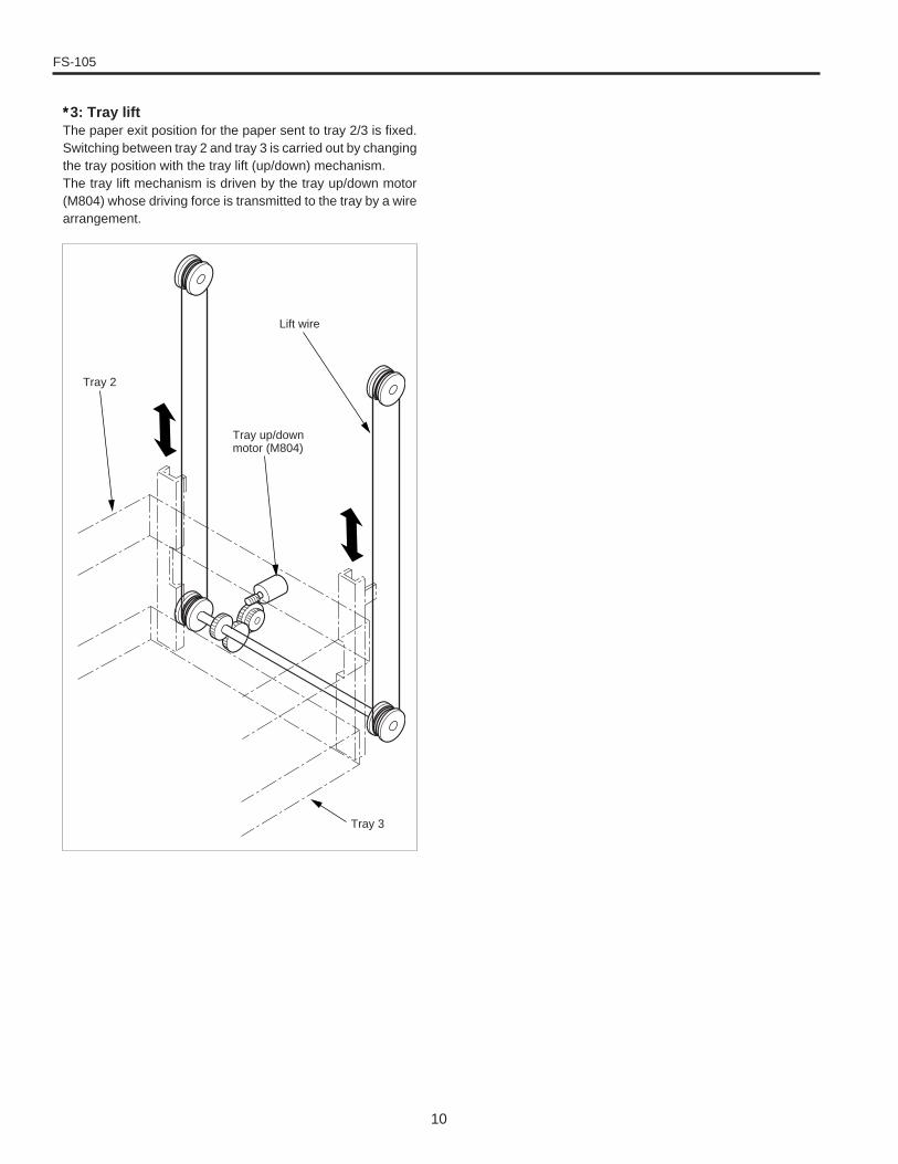
∗∗∗∗∗3: Tray liftThe paper exit position for the paper sent to tray 2/3 is fixed.Switching between tray 2 and tray 3 is carried out by changingthe tray position with the tray lift (up/down) mechanism.The tray lift mechanism is driven by the tray up/down motor(M804) whose driving force is transmitted to the tray by a wirearrangement.
Tray 2
Lift wire
Tray 3
Tray up/downmotor (M804)
11
FS-105
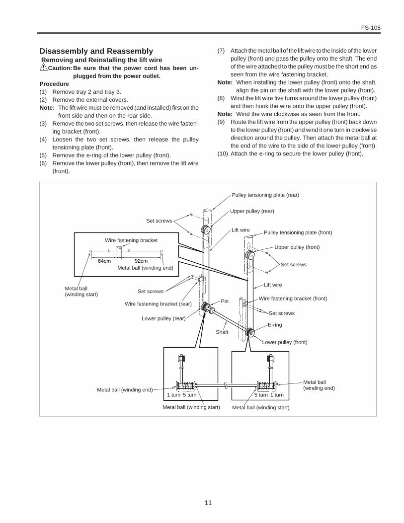
Disassembly and Reassembly Removing and Reinstalling the lift wire
Caution: Be sure that the power cord has been un-plugged from the power outlet.
Procedure(1) Remove tray 2 and tray 3.(2) Remove the external covers.Note: The lift wire must be removed (and installed) first on the
front side and then on the rear side.(3) Remove the two set screws, then release the wire fasten-
ing bracket (front).(4) Loosen the two set screws, then release the pulley
tensioning plate (front).(5) Remove the e-ring of the lower pulley (front).(6) Remove the lower pulley (front), then remove the lift wire
(front).
(7) Attach the metal ball of the lift wire to the inside of the lowerpulley (front) and pass the pulley onto the shaft. The endof the wire attached to the pulley must be the short end asseen from the wire fastening bracket.
Note: When installing the lower pulley (front) onto the shaft,align the pin on the shaft with the lower pulley (front).
(8) Wind the lift wire five turns around the lower pulley (front)and then hook the wire onto the upper pulley (front).
Note: Wind the wire clockwise as seen from the front.(9) Route the lift wire from the upper pulley (front) back down
to the lower pulley (front) and wind it one turn in clockwisedirection around the pulley. Then attach the metal ball atthe end of the wire to the side of the lower pulley (front).
(10) Attach the e-ring to secure the lower pulley (front).
Metal ball(winding start)
Pulley tensioning plate (rear)
Upper pulley (rear)
Lift wire
Set screws
Metal ball (winding end)Metal ball(winding end)
Pulley tensioning plate (front)
Upper pulley (front)
Set screws
Lift wire
Wire fastening bracket (front)
Set screws
E-ring
Lower pulley (front)
Lower pulley (rear)
Set screws
Metal ball (winding start) Metal ball (winding start)
1 turn5 turn
Shaft
PinWire fastening bracket (rear)
Metal ball (winding end)
1 turn 5 turn
Wire fastening bracket
FS-105
12
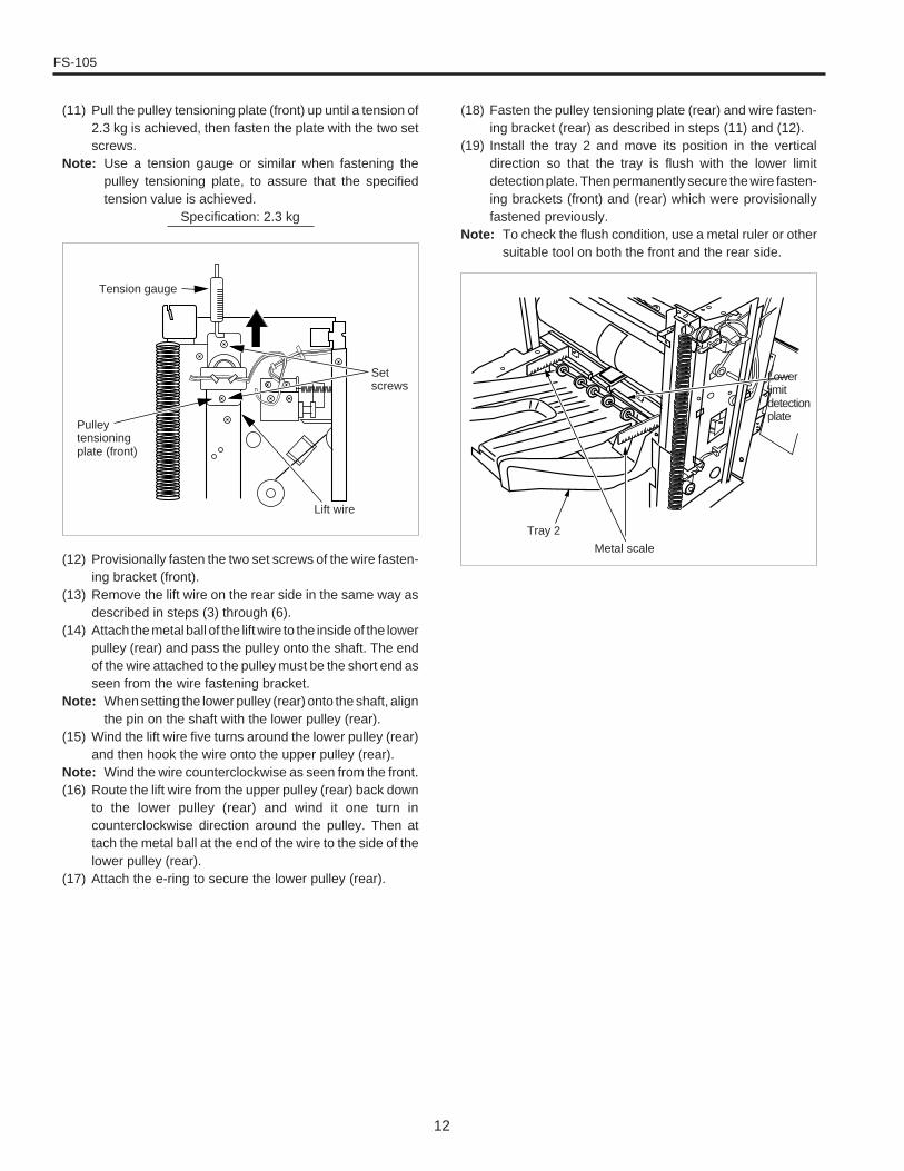
(11) Pull the pulley tensioning plate (front) up until a tension of2.3 kg is achieved, then fasten the plate with the two setscrews.
Note: Use a tension gauge or similar when fastening thepulley tensioning plate, to assure that the specifiedtension value is achieved.
Specification: 2.3 kg
(12) Provisionally fasten the two set screws of the wire fasten-ing bracket (front).
(13) Remove the lift wire on the rear side in the same way asdescribed in steps (3) through (6).
(14) Attach the metal ball of the lift wire to the inside of the lowerpulley (rear) and pass the pulley onto the shaft. The endof the wire attached to the pulley must be the short end asseen from the wire fastening bracket.
Note: When setting the lower pulley (rear) onto the shaft, alignthe pin on the shaft with the lower pulley (rear).
(15) Wind the lift wire five turns around the lower pulley (rear)and then hook the wire onto the upper pulley (rear).
Note: Wind the wire counterclockwise as seen from the front.(16) Route the lift wire from the upper pulley (rear) back down
to the lower pulley (rear) and wind it one turn incounterclockwise direction around the pulley. Then attach the metal ball at the end of the wire to the side of thelower pulley (rear).
(17) Attach the e-ring to secure the lower pulley (rear).
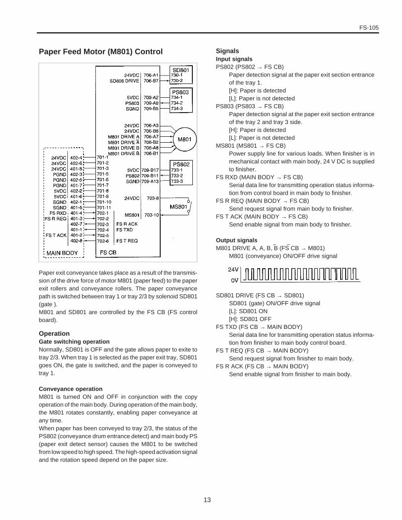
(18) Fasten the pulley tensioning plate (rear) and wire fasten-ing bracket (rear) as described in steps (11) and (12).
(19) Install the tray 2 and move its position in the verticaldirection so that the tray is flush with the lower limitdetection plate. Then permanently secure the wire fasten-ing brackets (front) and (rear) which were provisionallyfastened previously.
Note: To check the flush condition, use a metal ruler or othersuitable tool on both the front and the rear side.
Setscrews
Pulleytensioningplate (front)
Tension gauge
Lift wire
Metal scale
Tray 2
Lowerlimitdetectionplate
13
FS-105
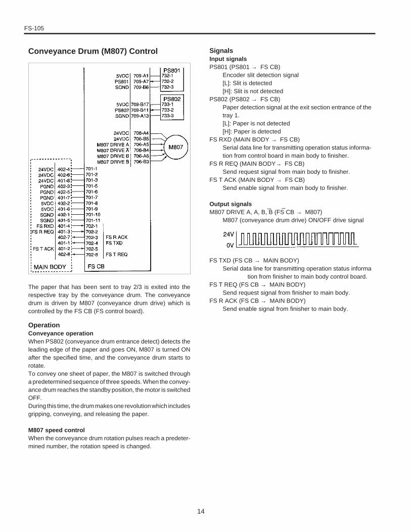
Paper exit conveyance takes place as a result of the transmis-sion of the drive force of motor M801 (paper feed) to the paperexit rollers and conveyance rollers. The paper conveyancepath is switched between tray 1 or tray 2/3 by solenoid SD801(gate ).M801 and SD801 are controlled by the FS CB (FS controlboard).
OperationGate switching operationNormally, SD801 is OFF and the gate allows paper to exite totray 2/3. When tray 1 is selected as the paper exit tray, SD801goes ON, the gate is switched, and the paper is conveyed totray 1.
Conveyance operationM801 is turned ON and OFF in conjunction with the copyoperation of the main body. During operation of the main body,the M801 rotates constantly, enabling paper conveyance atany time.When paper has been conveyed to tray 2/3, the status of thePS802 (conveyance drum entrance detect) and main body PS(paper exit detect sensor) causes the M801 to be switchedfrom low speed to high speed. The high-speed activation signaland the rotation speed depend on the paper size.
Paper Feed Motor (M801) Control SignalsInput signalsPS802 (PS802 → FS CB)
Paper detection signal at the paper exit section entranceof the tray 1.[H]: Paper is detected[L]: Paper is not detected
PS803 (PS803 → FS CB)Paper detection signal at the paper exit section entranceof the tray 2 and tray 3 side.[H]: Paper is detected[L]: Paper is not detected
MS801 (MS801 → FS CB)Power supply line for various loads. When finisher is inmechanical contact with main body, 24 V DC is suppliedto finisher.
FS RXD (MAIN BODY → FS CB)Serial data line for transmitting operation status informa-tion from control board in main body to finisher.
FS R REQ (MAIN BODY → FS CB)Send request signal from main body to finisher.
FS T ACK (MAIN BODY → FS CB)Send enable signal from main body to finisher.
Output signalsM801 DRIVE A, A, B, B (FS CB → M801)
M801 (conveyance) ON/OFF drive signal
SD801 DRIVE (FS CB → SD801)SD801 (gate) ON/OFF drive signal[L]: SD801 ON[H]: SD801 OFF
FS TXD (FS CB → MAIN BODY)Serial data line for transmitting operation status informa-tion from finisher to main body control board.
FS T REQ (FS CB → MAIN BODY)Send request signal from finisher to main body.
FS R ACK (FS CB → MAIN BODY)Send enable signal from finisher to main body.
FS-105
14
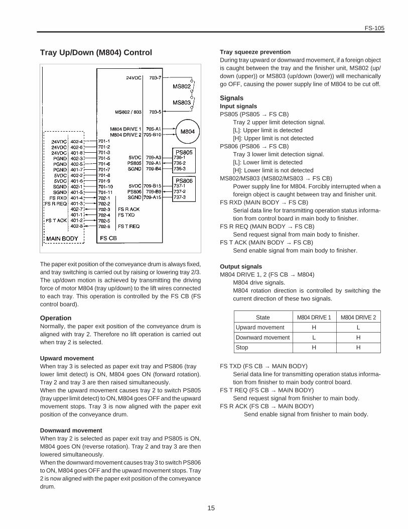
The paper that has been sent to tray 2/3 is exited into therespective tray by the conveyance drum. The conveyancedrum is driven by M807 (conveyance drum drive) which iscontrolled by the FS CB (FS control board).
OperationConveyance operationWhen PS802 (conveyance drum entrance detect) detects theleading edge of the paper and goes ON, M807 is turned ONafter the specified time, and the conveyance drum starts torotate.To convey one sheet of paper, the M807 is switched througha predetermined sequence of three speeds. When the convey-ance drum reaches the standby position, the motor is switchedOFF.During this time, the drum makes one revolution which includesgripping, conveying, and releasing the paper.
M807 speed controlWhen the conveyance drum rotation pulses reach a predeter-mined number, the rotation speed is changed.
Conveyance Drum (M807) Control SignalsInput signalsPS801 (PS801 → FS CB)
Encoder slit detection signal[L]: Slit is detected[H]: Slit is not detected
PS802 (PS802 → FS CB)Paper detection signal at the exit section entrance of thetray 1.[L]: Paper is not detected[H]: Paper is detected
FS RXD (MAIN BODY → FS CB)Serial data line for transmitting operation status informa-tion from control board in main body to finisher.
FS R REQ (MAIN BODY→ FS CB)Send request signal from main body to finisher.
FS T ACK (MAIN BODY → FS CB)Send enable signal from main body to finisher.
Output signalsM807 DRIVE A, A, B, B (FS CB → M807)
M807 (conveyance drum drive) ON/OFF drive signal
FS TXD (FS CB → MAIN BODY)Serial data line for transmitting operation status informa
tion from finisher to main body control board.FS T REQ (FS CB → MAIN BODY)
Send request signal from finisher to main body.FS R ACK (FS CB → MAIN BODY)
Send enable signal from finisher to main body.
FS-105
15
Tray Up/Down (M804) Control
The paper exit position of the conveyance drum is always fixed,and tray switching is carried out by raising or lowering tray 2/3.The up/down motion is achieved by transmitting the drivingforce of motor M804 (tray up/down) to the lift wires connectedto each tray. This operation is controlled by the FS CB (FScontrol board).
OperationNormally, the paper exit position of the conveyance drum isaligned with tray 2. Therefore no lift operation is carried outwhen tray 2 is selected.
Upward movementWhen tray 3 is selected as paper exit tray and PS806 (traylower limit detect) is ON, M804 goes ON (forward rotation).Tray 2 and tray 3 are then raised simultaneously.When the upward movement causes tray 2 to switch PS805(tray upper limit detect) to ON, M804 goes OFF and the upwardmovement stops. Tray 3 is now aligned with the paper exitposition of the conveyance drum.
Downward movementWhen tray 2 is selected as paper exit tray and PS805 is ON,M804 goes ON (reverse rotation). Tray 2 and tray 3 are thenlowered simultaneously.When the downward movement causes tray 3 to switch PS806to ON, M804 goes OFF and the upward movement stops. Tray2 is now aligned with the paper exit position of the conveyancedrum.
FS TXD (FS CB → MAIN BODY)Serial data line for transmitting operation status informa-tion from finisher to main body control board.
FS T REQ (FS CB → MAIN BODY)Send request signal from finisher to main body.
FS R ACK (FS CB → MAIN BODY)Send enable signal from finisher to main body.
Tray squeeze preventionDuring tray upward or downward movement, if a foreign objectis caught between the tray and the finisher unit, MS802 (up/down (upper)) or MS803 (up/down (lower)) will mechanicallygo OFF, causing the power supply line of M804 to be cut off.
SignalsInput signalsPS805 (PS805 → FS CB)
Tray 2 upper limit detection signal.[L]: Upper limit is detected[H]: Upper limit is not detected
PS806 (PS806 → FS CB)Tray 3 lower limit detection signal.[L]: Lower limit is detected[H]: Lower limit is not detected
MS802/MS803 (MS802/MS803 → FS CB)Power supply line for M804. Forcibly interrupted when aforeign object is caught between tray and finisher unit.
FS RXD (MAIN BODY → FS CB)Serial data line for transmitting operation status informa-tion from control board in main body to finisher.
FS R REQ (MAIN BODY → FS CB)Send request signal from main body to finisher.
FS T ACK (MAIN BODY → FS CB)Send enable signal from main body to finisher.
Output signalsM804 DRIVE 1, 2 (FS CB → M804)
M804 drive signals.M804 rotation direction is controlled by switching thecurrent direction of these two signals.
State
Upward movement
Downward movement
Stop
M804 DRIVE 2
L
H
H
M804 DRIVE 1
H
L
H
FS-105
16
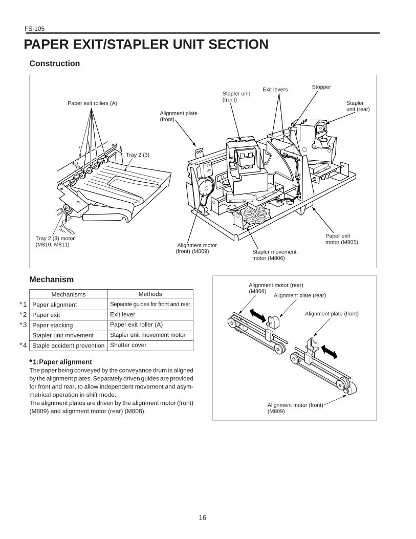
Construction
Mechanism
Paper exit rollers (A)
Tray 2 (3) motor(M810, M811)
Stapler movementmotor (M806)
Alignment motor(front) (M809)
Tray 2 (3)
Alignment plate(front)
Stapler unit(front)
Exit levers Stopper
Staplerunit (rear)
Paper exitmotor (M805)
Alignment plate (front)
Alignment plate (rear)
Alignment motor (rear)(M808)
Alignment motor (front)(M809)
Mechanisms
Paper alignment
Paper exit
Paper stacking
Stapler unit movement
Staple accident prevention
Methods
Separate guides for front and rear
Exit lever
Paper exit roller (A)
Stapler unit movement motor
Shutter cover
∗∗∗∗∗1:Paper alignmentThe paper being conveyed by the conveyance drum is alignedby the alignment plates. Separately driven guides are providedfor front and rear, to allow independent movement and asym-metrical operation in shift mode.The alignment plates are driven by the alignment motor (front)(M809) and alignment motor (rear) (M808).
∗1
∗2
∗3
∗4
PAPER EXIT/STAPLER UNIT SECTION
FS-105
17
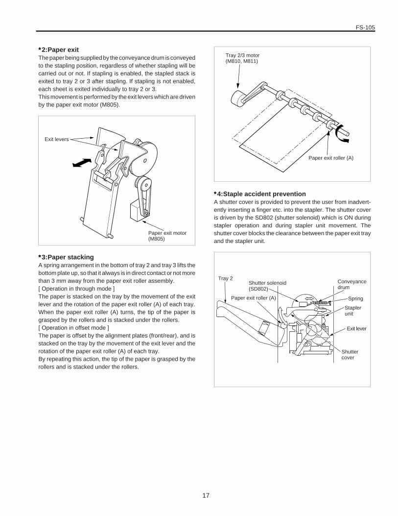
∗∗∗∗∗2:Paper exitThe paper being supplied by the conveyance drum is conveyedto the stapling position, regardless of whether stapling will becarried out or not. If stapling is enabled, the stapled stack isexited to tray 2 or 3 after stapling. If stapling is not enabled,each sheet is exited individually to tray 2 or 3.This movement is performed by the exit levers which are drivenby the paper exit motor (M805).
∗∗∗∗∗4:Staple accident preventionA shutter cover is provided to prevent the user from inadvert-ently inserting a finger etc. into the stapler. The shutter coveris driven by the SD802 (shutter solenoid) which is ON duringstapler operation and during stapler unit movement. Theshutter cover blocks the clearance between the paper exit trayand the stapler unit.
∗∗∗∗∗3:Paper stackingA spring arrangement in the bottom of tray 2 and tray 3 lifts thebottom plate up, so that it always is in direct contact or not morethan 3 mm away from the paper exit roller assembly.[ Operation in through mode ]The paper is stacked on the tray by the movement of the exitlever and the rotation of the paper exit roller (A) of each tray.When the paper exit roller (A) turns, the tip of the paper isgrasped by the rollers and is stacked under the rollers.[ Operation in offset mode ]The paper is offset by the alignment plates (front/rear), and isstacked on the tray by the movement of the exit lever and therotation of the paper exit roller (A) of each tray.By repeating this action, the tip of the paper is grasped by therollers and is stacked under the rollers.
Exit levers
Paper exit motor(M805)
Tray 2Shutter solenoid(SD802)
Paper exit roller (A)
Shuttercover
Staplerunit
Conveyancedrum
Spring
Exit lever
Tray 2/3 motor(M810, M811)
Paper exit roller (A)
FS-105
18
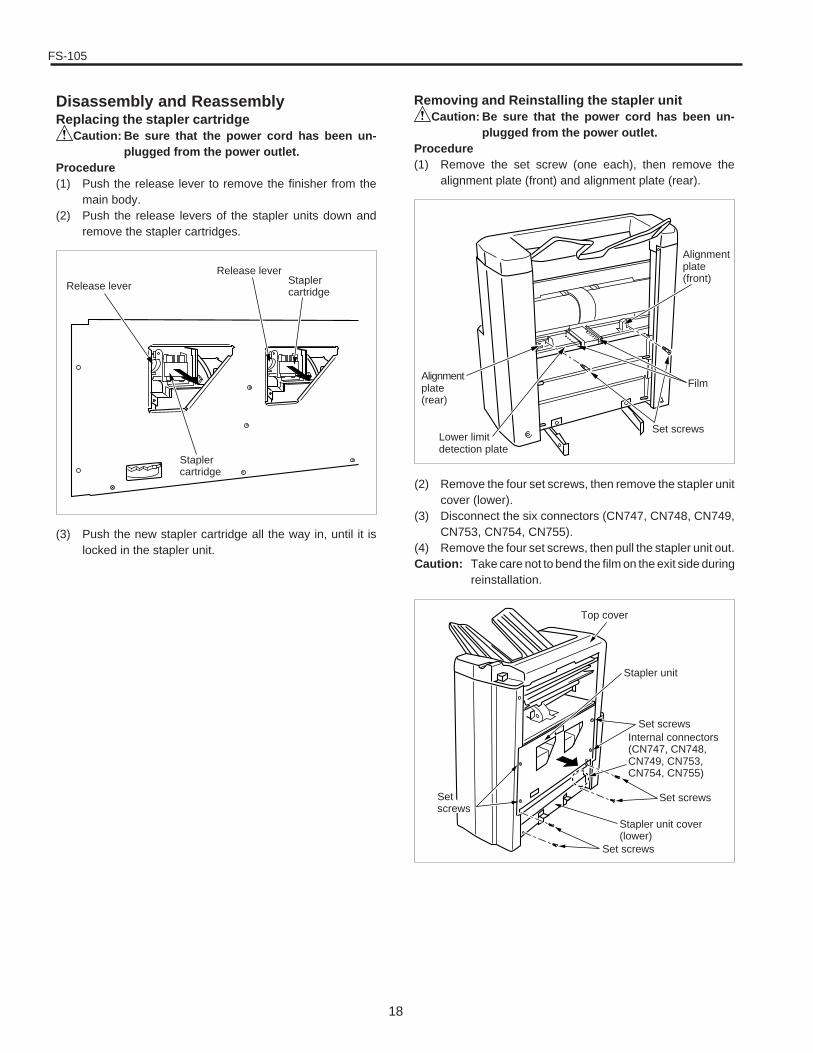
Disassembly and ReassemblyReplacing the stapler cartridge
Caution: Be sure that the power cord has been un-plugged from the power outlet.
Procedure(1) Push the release lever to remove the finisher from the
main body.(2) Push the release levers of the stapler units down and
remove the stapler cartridges.
Removing and Reinstalling the stapler unitCaution: Be sure that the power cord has been un-
plugged from the power outlet.Procedure(1) Remove the set screw (one each), then remove the
alignment plate (front) and alignment plate (rear).
Release leverRelease lever
Staplercartridge
Staplercartridge
Film
Set screwsLower limitdetection plate
Alignmentplate(rear)
Alignmentplate(front)
(2) Remove the four set screws, then remove the stapler unitcover (lower).
(3) Disconnect the six connectors (CN747, CN748, CN749,CN753, CN754, CN755).
(4) Remove the four set screws, then pull the stapler unit out.Caution: Take care not to bend the film on the exit side during
reinstallation.
(3) Push the new stapler cartridge all the way in, until it islocked in the stapler unit.
Top cover
Stapler unit
Set screws
Set screws
Stapler unit cover(lower)
Set screws
Setscrews
Internal connectors(CN747, CN748,CN749, CN753,CN754, CN755)
FS-105
19
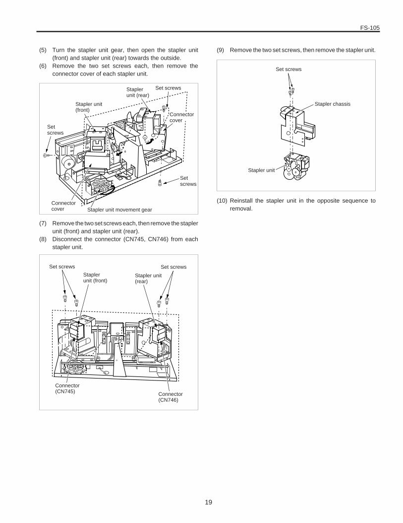
(5) Turn the stapler unit gear, then open the stapler unit(front) and stapler unit (rear) towards the outside.
(6) Remove the two set screws each, then remove theconnector cover of each stapler unit.
(9) Remove the two set screws, then remove the stapler unit.
Set screws
Stapler unit(front)
Staplerunit (rear)
Setscrews
Stapler unit movement gearConnectorcover
Setscrews
Connectorcover
Set screws
Staplerunit (front)
Stapler unit(rear)
Set screws
Connector(CN745) Connector
(CN746)
(10) Reinstall the stapler unit in the opposite sequence toremoval.
Stapler unit
Stapler chassis
Set screws
(7) Remove the two set screws each, then remove the staplerunit (front) and stapler unit (rear).
(8) Disconnect the connector (CN745, CN746) from eachstapler unit.
FS-105
20
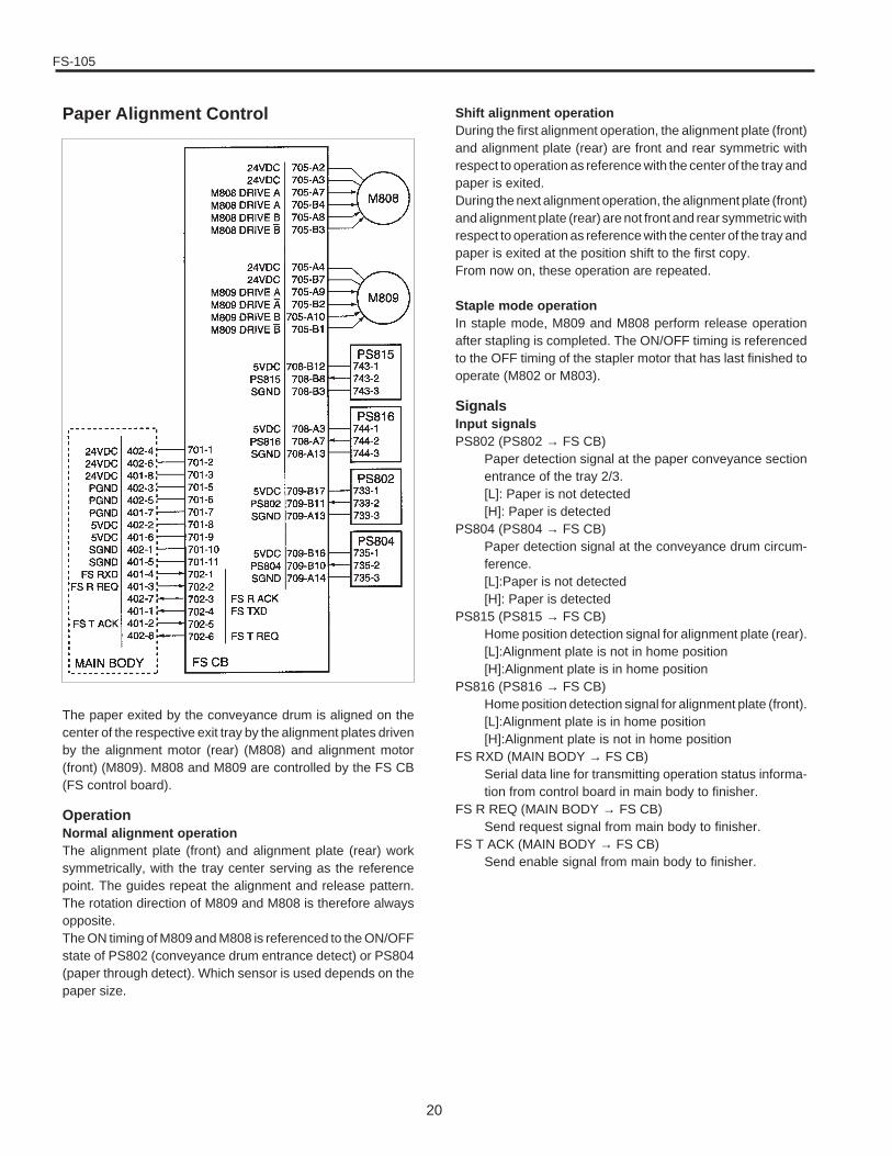
Paper Alignment Control
The paper exited by the conveyance drum is aligned on thecenter of the respective exit tray by the alignment plates drivenby the alignment motor (rear) (M808) and alignment motor(front) (M809). M808 and M809 are controlled by the FS CB(FS control board).
OperationNormal alignment operationThe alignment plate (front) and alignment plate (rear) worksymmetrically, with the tray center serving as the referencepoint. The guides repeat the alignment and release pattern.The rotation direction of M809 and M808 is therefore alwaysopposite.The ON timing of M809 and M808 is referenced to the ON/OFFstate of PS802 (conveyance drum entrance detect) or PS804(paper through detect). Which sensor is used depends on thepaper size.
Shift alignment operationDuring the first alignment operation, the alignment plate (front)and alignment plate (rear) are front and rear symmetric withrespect to operation as reference with the center of the tray andpaper is exited.During the next alignment operation, the alignment plate (front)and alignment plate (rear) are not front and rear symmetric withrespect to operation as reference with the center of the tray andpaper is exited at the position shift to the first copy.From now on, these operation are repeated.
Staple mode operationIn staple mode, M809 and M808 perform release operationafter stapling is completed. The ON/OFF timing is referencedto the OFF timing of the stapler motor that has last finished tooperate (M802 or M803).
SignalsInput signalsPS802 (PS802 → FS CB)
Paper detection signal at the paper conveyance sectionentrance of the tray 2/3.[L]: Paper is not detected[H]: Paper is detected
PS804 (PS804 → FS CB)Paper detection signal at the conveyance drum circum-ference.[L]:Paper is not detected[H]: Paper is detected
PS815 (PS815 → FS CB)Home position detection signal for alignment plate (rear).[L]:Alignment plate is not in home position[H]:Alignment plate is in home position
PS816 (PS816 → FS CB)Home position detection signal for alignment plate (front).[L]:Alignment plate is in home position[H]:Alignment plate is not in home position
FS RXD (MAIN BODY → FS CB)Serial data line for transmitting operation status informa-tion from control board in main body to finisher.
FS R REQ (MAIN BODY → FS CB)Send request signal from main body to finisher.
FS T ACK (MAIN BODY → FS CB)Send enable signal from main body to finisher.
FS-105
21
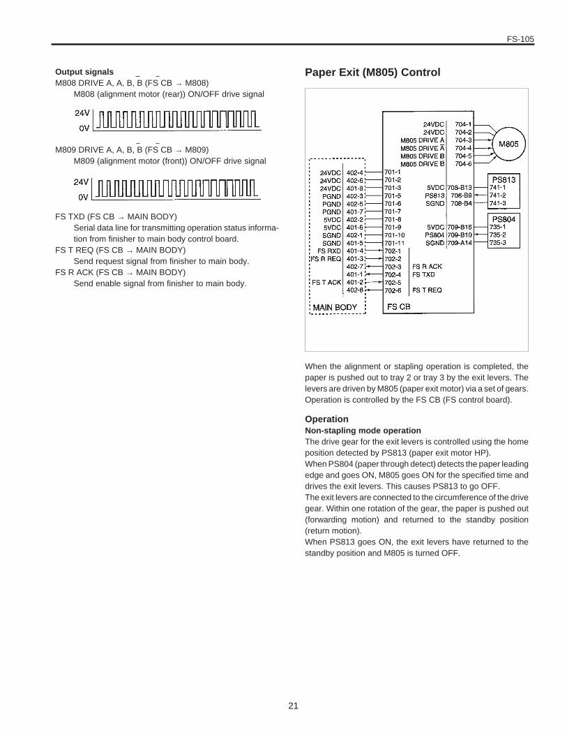
Output signalsM808 DRIVE A, A, B, B (FS CB → M808)
M808 (alignment motor (rear)) ON/OFF drive signal
M809 DRIVE A, A, B, B (FS CB → M809)M809 (alignment motor (front)) ON/OFF drive signal
FS TXD (FS CB → MAIN BODY)Serial data line for transmitting operation status informa-tion from finisher to main body control board.
FS T REQ (FS CB → MAIN BODY)Send request signal from finisher to main body.
FS R ACK (FS CB → MAIN BODY)Send enable signal from finisher to main body.
When the alignment or stapling operation is completed, thepaper is pushed out to tray 2 or tray 3 by the exit levers. Thelevers are driven by M805 (paper exit motor) via a set of gears.Operation is controlled by the FS CB (FS control board).
OperationNon-stapling mode operationThe drive gear for the exit levers is controlled using the homeposition detected by PS813 (paper exit motor HP).When PS804 (paper through detect) detects the paper leadingedge and goes ON, M805 goes ON for the specified time anddrives the exit levers. This causes PS813 to go OFF.The exit levers are connected to the circumference of the drivegear. Within one rotation of the gear, the paper is pushed out(forwarding motion) and returned to the standby position(return motion).When PS813 goes ON, the exit levers have returned to thestandby position and M805 is turned OFF.
Paper Exit (M805) Control
FS-105
22
Stapling mode operationIn stapling mode, when the stapler motor (M802 or M803) thathas last finished to operate goes OFF, M805 goes ON for thespecified time and drives the exit levers. Other operations arethe same as for non-stapling mode.
SignalsInput signalsPS804 (PS804 → FS CB)
Paper detection signal at the conveyance drum circum-ference.[L]: Paper is not detected[H]: Paper is detected
PS813 (PS813 → FS CB)Home position detection signal for exit lever.[L]: Exit lever is not in home position[H]: Exit lever is in home position
FS RXD (MAIN BODY → FS CB)Serial data line for transmitting operation status informa-tion from control board in main body to finisher.
FS R REQ (MAIN BODY → FS CB)Send request signal from main body to finisher.
FS T ACK (MAIN BODY → FS CB)Send enable signal from main body to finisher.
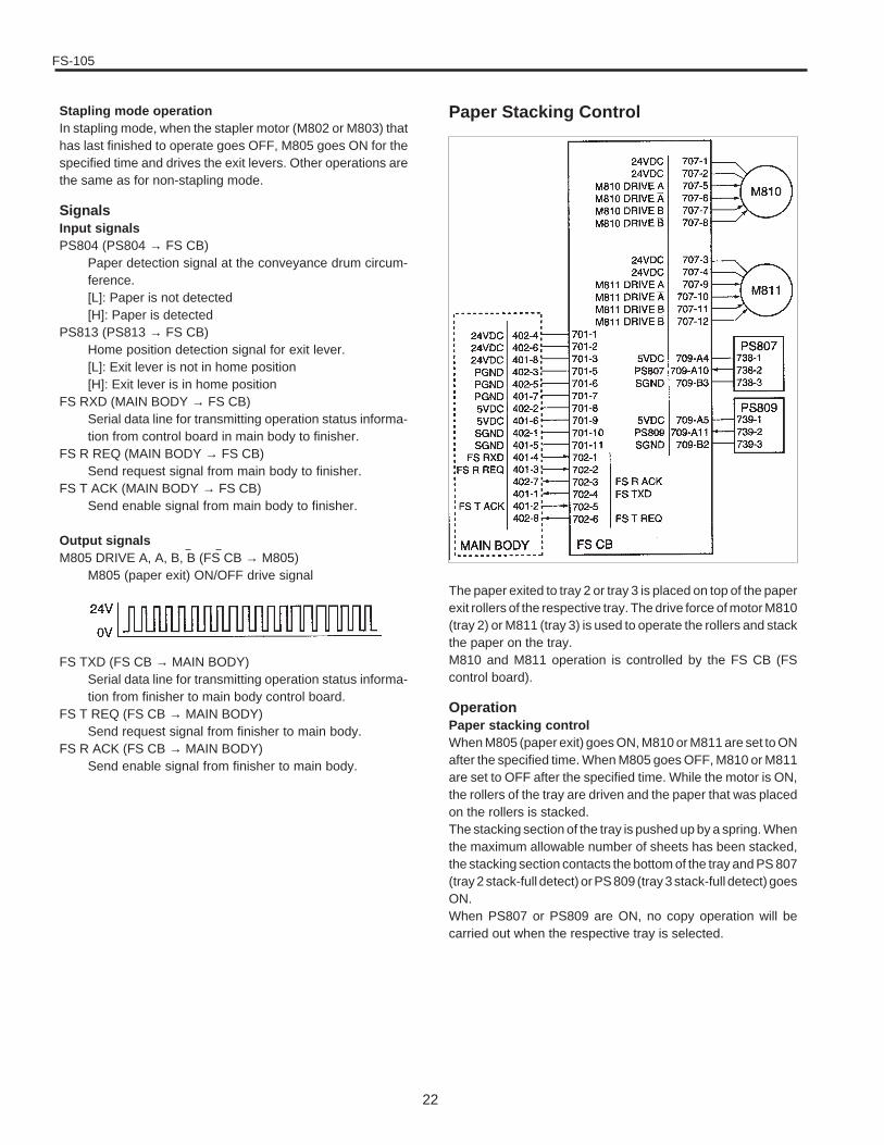
Output signalsM805 DRIVE A, A, B, B (FS CB → M805)
M805 (paper exit) ON/OFF drive signal
FS TXD (FS CB → MAIN BODY)Serial data line for transmitting operation status informa-tion from finisher to main body control board.
FS T REQ (FS CB → MAIN BODY)Send request signal from finisher to main body.
FS R ACK (FS CB → MAIN BODY)Send enable signal from finisher to main body.
The paper exited to tray 2 or tray 3 is placed on top of the paperexit rollers of the respective tray. The drive force of motor M810(tray 2) or M811 (tray 3) is used to operate the rollers and stackthe paper on the tray.M810 and M811 operation is controlled by the FS CB (FScontrol board).
OperationPaper stacking controlWhen M805 (paper exit) goes ON, M810 or M811 are set to ONafter the specified time. When M805 goes OFF, M810 or M811are set to OFF after the specified time. While the motor is ON,the rollers of the tray are driven and the paper that was placedon the rollers is stacked.The stacking section of the tray is pushed up by a spring. Whenthe maximum allowable number of sheets has been stacked,the stacking section contacts the bottom of the tray and PS 807(tray 2 stack-full detect) or PS 809 (tray 3 stack-full detect) goesON.When PS807 or PS809 are ON, no copy operation will becarried out when the respective tray is selected.
Paper Stacking Control
FS-105
23
Tray auto-switching controlWhen copying is carried out with tray 2 or tray 3 specified asoutput tray and the specified tray becomes full, causing PS807or PS809 to become ON, the output tray is automaticallyswitched to the other tray.This operation is also valid if tray 1 is specified as the outputtray. The output tray will be switched to tray 2 or tray 3.Normally, tray 2 will be selected. If it is full, tray 3 will beselected. Switching from tray 2 or tray 3 to tray 1 is not possible.
SignalsInput signalsPS807 (PS807 → FS CB)
Tray 2 stack-full detection signal[L]: Stack full condition not detected[H]: Stack full condition detected
PS809 (PS809 → FS CB)Tray 3 stack-full detection signal[L]: Stack full condition not detected[H]: Stack full condition detected
FS RXD (MAIN BODY → FS CB)Serial data line for transmitting operation status informa-tion from control board in main body to finisher.
FS R REQ (MAIN BODY → FS CB)Send request signal from main body to finisher
FS T ACK (MAIN BODY → FS CB)Send enable signal from main body to finisher
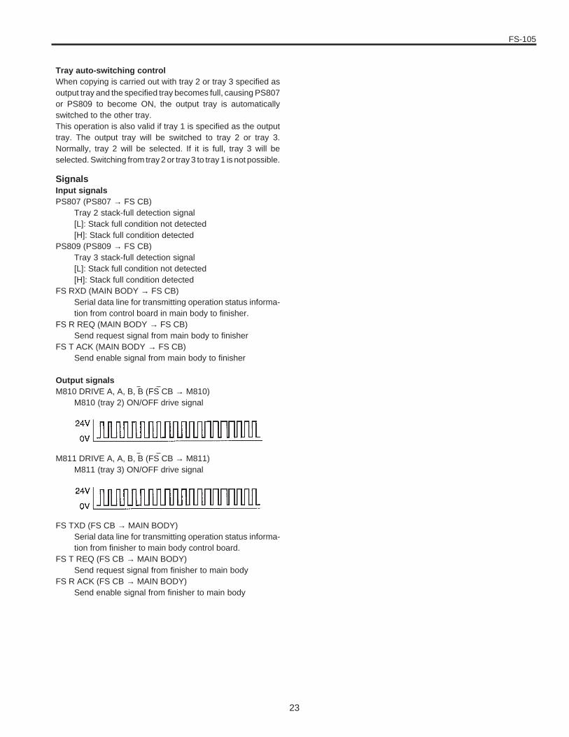
Output signalsM810 DRIVE A, A, B, B (FS CB → M810)
M810 (tray 2) ON/OFF drive signal
M811 DRIVE A, A, B, B (FS CB → M811)M811 (tray 3) ON/OFF drive signal
FS TXD (FS CB → MAIN BODY)Serial data line for transmitting operation status informa-tion from finisher to main body control board.
FS T REQ (FS CB → MAIN BODY)Send request signal from finisher to main body
FS R ACK (FS CB → MAIN BODY)Send enable signal from finisher to main body
FS-105
24
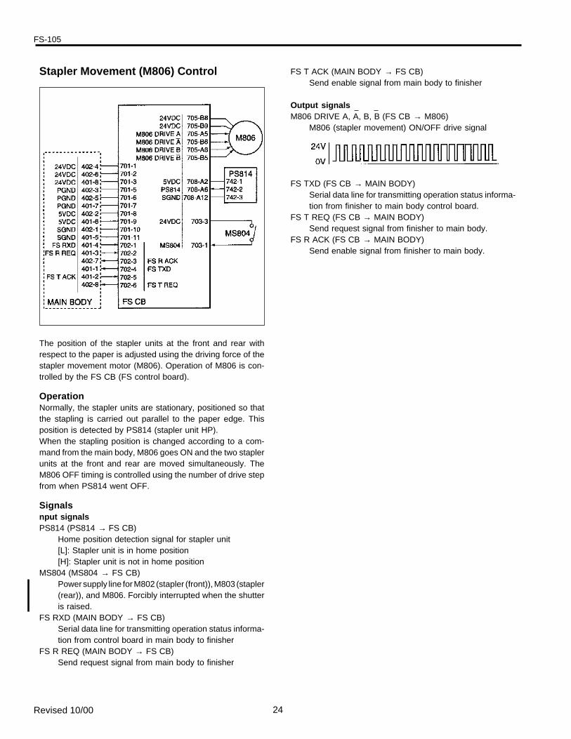
The position of the stapler units at the front and rear withrespect to the paper is adjusted using the driving force of thestapler movement motor (M806). Operation of M806 is con-trolled by the FS CB (FS control board).
OperationNormally, the stapler units are stationary, positioned so thatthe stapling is carried out parallel to the paper edge. Thisposition is detected by PS814 (stapler unit HP).When the stapling position is changed according to a com-mand from the main body, M806 goes ON and the two staplerunits at the front and rear are moved simultaneously. TheM806 OFF timing is controlled using the number of drive stepfrom when PS814 went OFF.
Signalsnput signalsPS814 (PS814 → FS CB)
Home position detection signal for stapler unit[L]: Stapler unit is in home position[H]: Stapler unit is not in home position
MS804 (MS804 → FS CB)Power supply line for M802 (stapler (front)), M803 (stapler(rear)), and M806. Forcibly interrupted when the shutteris raised.
FS RXD (MAIN BODY → FS CB)Serial data line for transmitting operation status informa-tion from control board in main body to finisher
FS R REQ (MAIN BODY → FS CB)Send request signal from main body to finisher
Stapler Movement (M806) Control FS T ACK (MAIN BODY → FS CB)Send enable signal from main body to finisher
Output signalsM806 DRIVE A, A, B, B (FS CB → M806)
M806 (stapler movement) ON/OFF drive signal
FS TXD (FS CB → MAIN BODY)Serial data line for transmitting operation status informa-tion from finisher to main body control board.
FS T REQ (FS CB → MAIN BODY)Send request signal from finisher to main body.
FS R ACK (FS CB → MAIN BODY)Send enable signal from finisher to main body.
Revised 10/00
FS-105
25
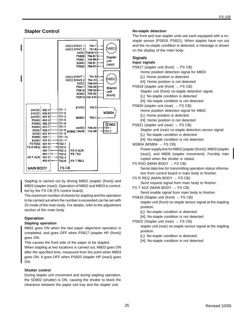
Stapling is carried out by driving M802 (stapler (front)) andM803 (stapler (rear)). Operation of M802 and M803 is control-led by the FS CB (FS control board).The maximum number of sheets for stapling and the operationto be carried out when the number is exceeded can be set with25 mode of the main body. For details, refer to the adjustmentsection of the main body
OperationStapling operationM802 goes ON when the last paper alignment operation iscompleted, and goes OFF when PS817 (stapler HP (front))goes ON.This causes the front side of the paper to be stapled.When stapling at two locations is carried out, M803 goes ONafter the specified time, measured from the point when M803goes ON. It goes OFF when PS820 (stapler HP (rear)) goesON.
Shutter controlDuring stapler unit movement and during stapling operation,the SD802 (shutter) is ON, causing the shutter to block theclearance between the paper exit tray and the stapler unit.
Stapler Control No-staple detectionThe front and rear stapler units are each equipped with a no-staple sensor (PS818, PS821). When staples have run outand the no-staple condition is detected, a message is shownon the display of the main body.
SignalsInput signalsPS817 (stapler unit (front) → FS CB)
Home position detection signal for M803[L]: Home position is detected[H]: Home position is not detected
PS818 (stapler unit (front) → FS CB)Stapler unit (front) no-staple detection signal.[L]: No-staple condition is detected[H]: No-staple condition is not detected
PS820 (stapler unit (rear) → FS CB)Home position detection signal for M802[L]: Home position is detected[H]: Home position is not detected
PS821 (stapler unit (rear) → FS CB)Stapler unit (rear) no-staple detection sensor signal[L]: No-staple condition is detected[H]: No-staple condition is not detected
MS804 (MS804 → FS CB)Power supply line for M802 (stapler (front)), M803 (stapler(rear)), and M806 (stapler movement). Forcibly interrupted when the shutter is raised.
FS RXD (MAIN BODY → FS CB)Serial data line for transmitting operation status informa-tion from control board in main body to finisher.
FS R REQ (MAIN BODY → FS CB)Send request signal from main body to finisher.
FS T ACK (MAIN BODY → FS CB)Send enable signal from main body to finisher.
PS819 (Stapler unit (front) → FS CB)stapler unit (front) no-staple sensor signal at the staplingposition.[L]: No-staple condition is detected[H]: No-staple condition is not detected
PS822 (Stapler unit (rear) → FS CB)stapler unit (rear) no-staple sensor signal at the staplingposition.[L]: No-staple condition is detected[H]: No-staple condition is not detected
M803
M802M802M802
M803M803
Revised 10/00
FS-105
26
Output signalsM802 DRIVE 1, 2 (FS CB → stapler unit (front))
M802 drive signals.M802 rotation direction is controlled by switching thecurrent direction of these two signals.
M803 DRIVE 1, 2 (FS CB → stapler unit (rear))M803 drive signals.M803 rotation direction is controlled by switching thecurrent direction of these two signals.
SD802 DRIVE (FS CB → SD802)SD802 (shutter) ON/OFF drive signal.[L]: SD802 ON[H]: SD802 OFF
FS TXD (FS CB → MAIN BODY)Serial data line for transmitting operation status informa-tion from finisher to main body control board.
FS T REQ (FS CB → MAIN BODY)Send request signal from finisher to main body.
FS R ACK (FS CB → MAIN BODY)Send enable signal from finisher to main body.
Revised 10/00
FS-105
27
Power-on OperationWhen the main body SW2 (sub power) is set to ON, the finisherperforms the following initialization sequence.
1. SD802 (shutter) goes ON and the shutter cover closes.
2. M808 (alignment (rear)) and M809 (alignment (front)) goON and the alignment plates (front/rear) perform homeposition search.
3. M807 (conveyance drum drive) goes ON and the convey-ance drum performs home position search.
4. M806 (stapler movement) goes ON and the stapler unitmoves to the standby position.
5. SD802 goes OFF and the shutter cover opens.
6. M805 (paper exit) goes ON and the exit lever is driven forone operation.
7. Lower limit position detection for tray 2 and tray 3 iscarried out. If PS806 (tray lower limit detect) does not goON, M804 (tray up/down) goes ON, causing tray 2 andtray 3 to move downward.
OTHER CONTROL FUNCTIONS
FS-105
28
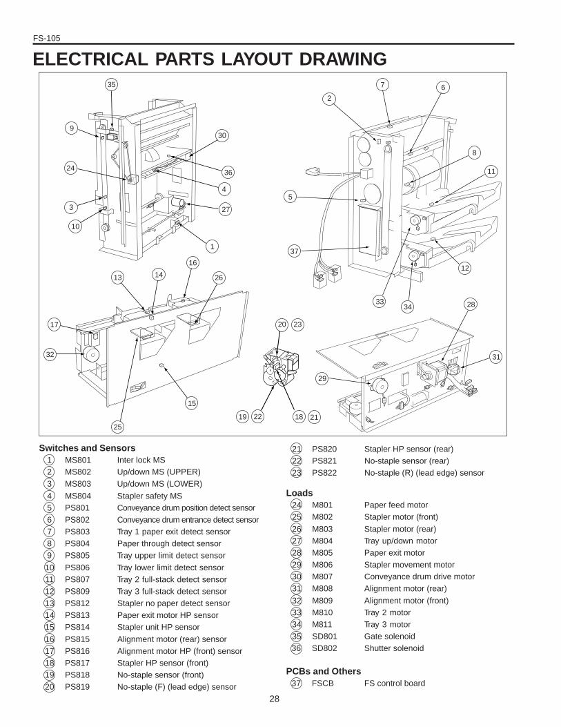
ELECTRICAL PARTS LAYOUT DRAWING
2
20 23
7 6
8
11
12
283433
31
2118
29
2219
15
25
32
17
13 14
16
26
1
27
4
36
30
35
9
24
3
10
37
5
Switches and Sensors1 MS801 Inter lock MS2 MS802 Up/down MS (UPPER)3 MS803 Up/down MS (LOWER)
4 MS804 Stapler safety MS5 PS801 Conveyance drum position detect sensor6 PS802 Conveyance drum entrance detect sensor7 PS803 Tray 1 paper exit detect sensor8 PS804 Paper through detect sensor9 PS805 Tray upper limit detect sensor
10 PS806 Tray lower limit detect sensor11 PS807 Tray 2 full-stack detect sensor12 PS809 Tray 3 full-stack detect sensor13 PS812 Stapler no paper detect sensor14 PS813 Paper exit motor HP sensor15 PS814 Stapler unit HP sensor
16 PS815 Alignment motor (rear) sensor17 PS816 Alignment motor HP (front) sensor18 PS817 Stapler HP sensor (front)19 PS818 No-staple sensor (front)20 PS819 No-staple (F) (lead edge) sensor
21 PS820 Stapler HP sensor (rear)22 PS821 No-staple sensor (rear)23 PS822 No-staple (R) (lead edge) sensor
Loads24 M801 Paper feed motor25 M802 Stapler motor (front)
26 M803 Stapler motor (rear)27 M804 Tray up/down motor28 M805 Paper exit motor29 M806 Stapler movement motor30 M807 Conveyance drum drive motor31 M808 Alignment motor (rear)
32 M809 Alignment motor (front)33 M810 Tray 2 motor34 M811 Tray 3 motor35 SD801 Gate solenoid36 SD802 Shutter solenoid
PCBs and Others37 FSCB FS control board
FS-105
29
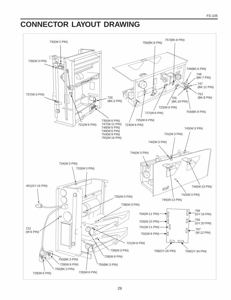
743(W:3 PIN)
741(W:3 PIN)
744(W:3 PIN)
740(W:3 PIN)
730(W:2 PIN) 756(BK:8 PIN)757(BK:8 PIN)
753(BK:8 PIN)755
(BK:19 PIN)
747(BK:12 PIN)
749(BK:6 PIN)
748(BK:7 PIN)
706(GY:16 PIN)
705(GY:20 PIN)
707(W:12 PIN)
401(GY:16 PIN)
734(W:3 PIN)
733(W:3 PIN)
735(W:3 PIN)
738(W:3 PIN)
722(W:6 PIN)
729(W:6 PIN)750(BK:3 PIN)
750(BK:3 PIN)
728(W:6 PIN)
729(W:6 PIN)
750(BK:3 PIN)
728(W:6 PIN)
739(W:3 PIN)
721(W:6 PIN)
708(GY:26 PIN) 709(GY:34 PIN)
704(W:11 PIN)
703(W:10 PIN)
701(W:11 PIN)
702(W:6 PIN)
745(W:13 PIN)
742(W:3 PIN)
746(W:13 PIN)
754(BK:9 PIN)
724(W:6 PIN)
725(W:6 PIN)
727(W:6 PIN)
723(W:6 PIN)
735(W:6 PIN)747(W:12 PIN)748(W:6 PIN)749(W:6 PIN)754(W:9 PIN)755(W:16 PIN)
726(BK:2 PIN)
736(W:3 PIN)
737(W:3 PIN)
721(W:6 PIN)
CONNECTOR LAYOUT DRAWING

FS-105
30
This page left blank intentionally.
PARTS CATALOG
MODEL
FS-105Used on Models 7033 & 7040
JUNE 1998
CSM --FS105
How to use this catalog
This parts catalog includes illustrations and part numbers for all replace-ment parts and assemblies used in this model.
Model-specific parts are identified in the illustrations with referencenumbers. Use the reference number to locate the corresponding partnumber on the facing page.
Common hardware items, such as screws, nuts, washers, and pins, areidentified in the illustrations with reference letters. Use the reference let-ter to locate the corresponding part number on the hardware listing in thelower right corner of the facing page.
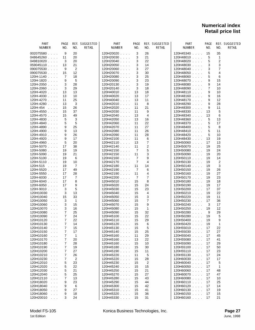
If you know a part number, but don’t know where the part is used, usethe numerical index to determine the page number and reference num-ber for that part. Because some common parts are used in severalplaces, there may be more than one entry. Refer to the illustrations to seewhere the part may be used.
If you know a part’s description, but don’t know where to look to findthe part number, use the alphabetical index to determine likely page andreference numbers. Then look at the illustrations to determine that youhave identified the correct part. Locate the part number using the listingon the opposite page.
Retail pricing that appears with the numerical index, while valid whenthis catalog was printed, is subject to change without notice. The pricesare only suggested prices and are provided only for reference. Dealersmay determine their own selling prices. For up-to-date pricing, refer tocurrent Konica price lists or contact the Konica Parts Distribution Center.
How to order parts
Use standard Konica parts ordering procedures to obtain these parts. Forordering options, contact Konica’s Parts Distribution Center.
When ordering parts, be sure to specify part numbers exactly as listed inthis catalog.
NOTE: Electrical parts may include previously used components.
Model FS-105 Konica Business Technologies, Inc. Page iii1st Edition June, 1998

This page left blank intentionally.
Page iv Konica Business Technologies, Inc. Model FS-105June, 1998 1st Edition
Contents
How to use this catalog . . . . . . . . . . . . . . . . . . . . . . . . . iiiContents . . . . . . . . . . . . . . . . . . . . . . . . . . . . . v
Machine partsFS-105 . . . . . . . . . . . . . . . . . . . . . . . . . . . . . 2
Wiring . . . . . . . . . . . . . . . . . . . . . . . . . . . . 20
Alphabetical index . . . . . . . . . . . . . . . . . . . . . . . . . . . 25Numerical index, Retail price list . . . . . . . . . . . . . . . . . . . . 27
Model FS-105 Konica Business Technologies, Inc. Page 11st Edition June, 1998
FS-105
Page 2 Konica Business Technologies., Inc. Model FS-105June, 1998 1st Edition
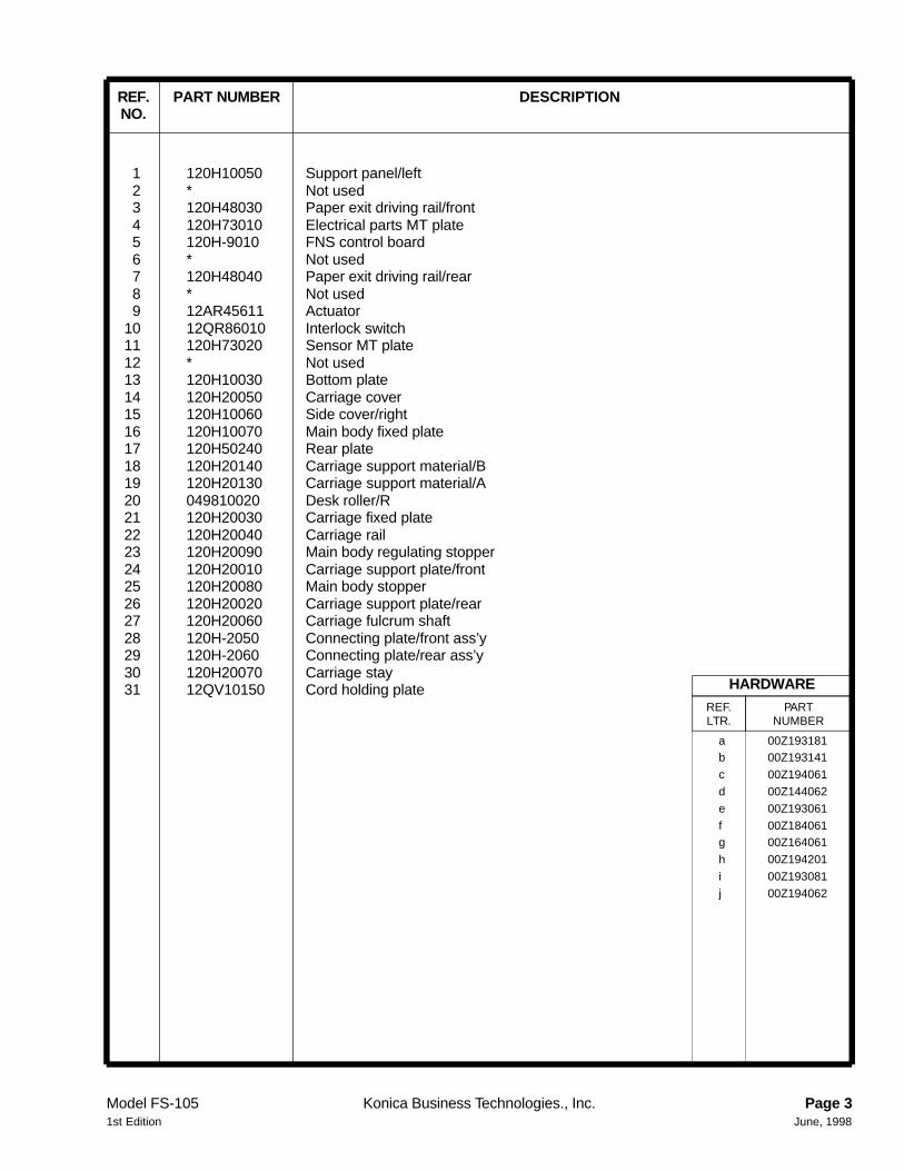
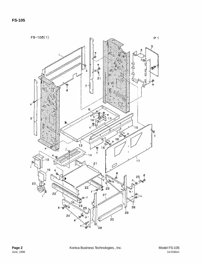
1 120H10050 Support panel/left2 * Not used3 120H48030 Paper exit driving rail/front4 120H73010 Electrical parts MT plate5 120H-9010 FNS control board6 * Not used7 120H48040 Paper exit driving rail/rear8 * Not used9 12AR45611 Actuator
10 12QR86010 Interlock switch11 120H73020 Sensor MT plate12 * Not used13 120H10030 Bottom plate14 120H20050 Carriage cover15 120H10060 Side cover/right16 120H10070 Main body fixed plate17 120H50240 Rear plate18 120H20140 Carriage support material/B19 120H20130 Carriage support material/A20 049810020 Desk roller/R21 120H20030 Carriage fixed plate22 120H20040 Carriage rail23 120H20090 Main body regulating stopper24 120H20010 Carriage support plate/front25 120H20080 Main body stopper26 120H20020 Carriage support plate/rear27 120H20060 Carriage fulcrum shaft28 120H-2050 Connecting plate/front ass’y29 120H-2060 Connecting plate/rear ass’y30 120H20070 Carriage stay31 12QV10150 Cord holding plate
a 00Z193181b 00Z193141
c 00Z194061
d 00Z144062
e 00Z193061
f 00Z184061g 00Z164061
h 00Z194201
i 00Z193081
j 00Z194062
HARDWAREREF.LTR.
PARTNUMBER
REF. PART NUMBER DESCRIPTIONNO.
Model FS-105 Konica Business Technologies., Inc. Page 31st Edition June, 1998
FS-105
Page 4 Konica Business Technologies., Inc. Model FS-105June, 1998 1st Edition
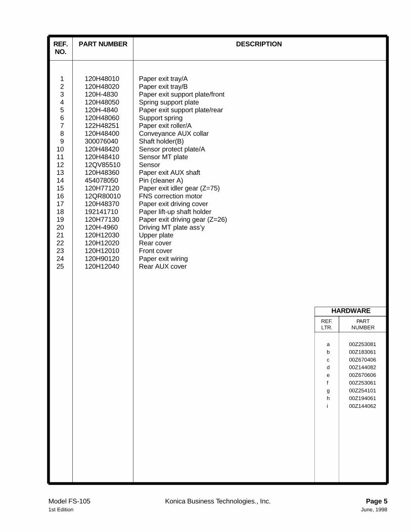
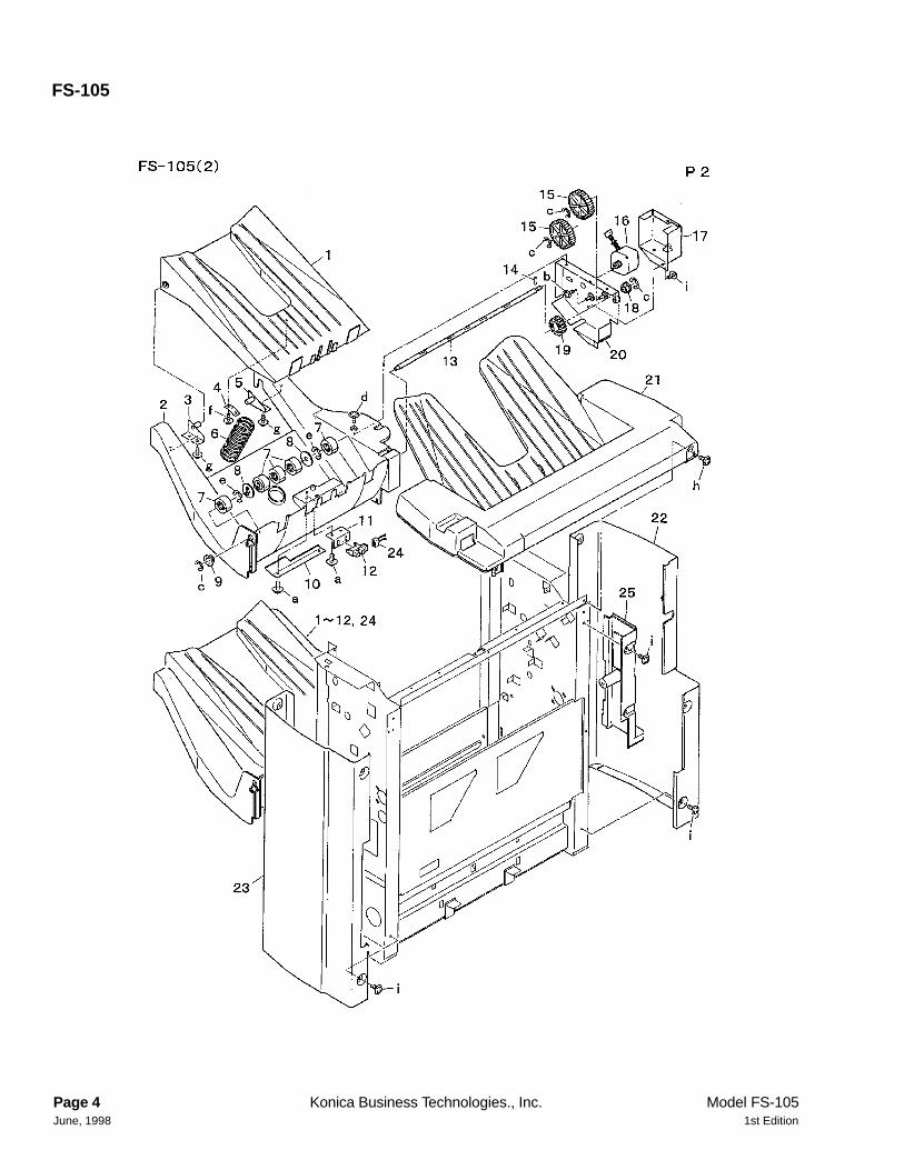
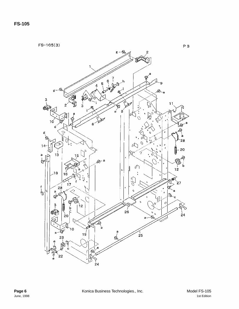
1 120H48010 Paper exit tray/A2 120H48020 Paper exit tray/B3 120H-4830 Paper exit support plate/front4 120H48050 Spring support plate5 120H-4840 Paper exit support plate/rear6 120H48060 Support spring7 122H48251 Paper exit roller/A8 120H48400 Conveyance AUX collar9 300076040 Shaft holder(B)
10 120H48420 Sensor protect plate/A11 120H48410 Sensor MT plate12 12QV85510 Sensor13 120H48360 Paper exit AUX shaft14 454078050 Pin (cleaner A)15 120H77120 Paper exit idler gear (Z=75)16 12QR80010 FNS correction motor17 120H48370 Paper exit driving cover18 192141710 Paper lift-up shaft holder19 120H77130 Paper exit driving gear (Z=26)20 120H-4960 Driving MT plate ass’y21 120H12030 Upper plate22 120H12020 Rear cover23 120H12010 Front cover24 120H90120 Paper exit wiring25 120H12040 Rear AUX cover
a 00Z253081
b 00Z183061
c 00Z670406d 00Z144082
e 00Z670606
f 00Z253061
g 00Z254101
h 00Z194061
i 00Z144062
HARDWAREREF.LTR.
PARTNUMBER
REF. PART NUMBER DESCRIPTIONNO.
Model FS-105 Konica Business Technologies., Inc. Page 51st Edition June, 1998
FS-105
Page 6 Konica Business Technologies., Inc. Model FS-105June, 1998 1st Edition
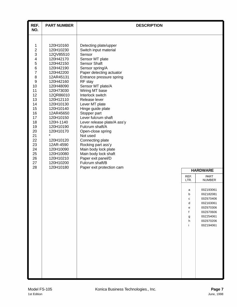
1 120H10160 Detecting plate/upper2 120H10230 Switch input material3 12QV85510 Sensor4 120H42170 Sensor MT plate5 120H42150 Sensor Shaft6 120H42190 Sensor spring/A7 120H42200 Paper detecting actuator8 12AR45131 Entrance pressure spring9 120H42160 RF stay
10 120H48090 Sensor MT plate/A11 120H73030 Wiring MT base12 12QR86010 Interlock switch13 120H12110 Release lever14 120H10130 Lever MT plate15 120H10140 Hinge guide plate16 12AR45650 Stopper part17 120H10150 Lever fulcrum shaft18 120H-1140 Lever release plate/A ass’y19 120H10190 Fulcrum shaft/A20 120H10170 Open-close spring21 * Not used22 120H10120 Connecting plate23 12AR-4590 Rocking part ass’y24 120H10090 Main body lock plate25 120H10080 Main body lock shaft26 120H10210 Paper exit panel/D27 120H10200 Fulcrum shaft/B28 120H10180 Paper exit protection cam
a 00Z193061b 00Z182081
c 00Z670406
d 00Z163061
e 00Z670306
f 00Z670606g 00Z254061
h 00Z670206
i 00Z194061
HARDWAREREF.LTR.
PARTNUMBER
REF. PART NUMBER DESCRIPTIONNO.
Model FS-105 Konica Business Technologies., Inc. Page 71st Edition June, 1998
FS-105
Page 8 Konica Business Technologies., Inc. Model FS-105June, 1998 1st Edition
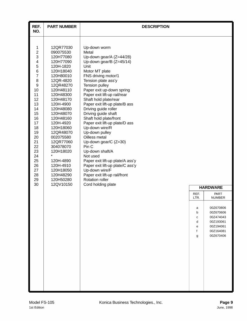
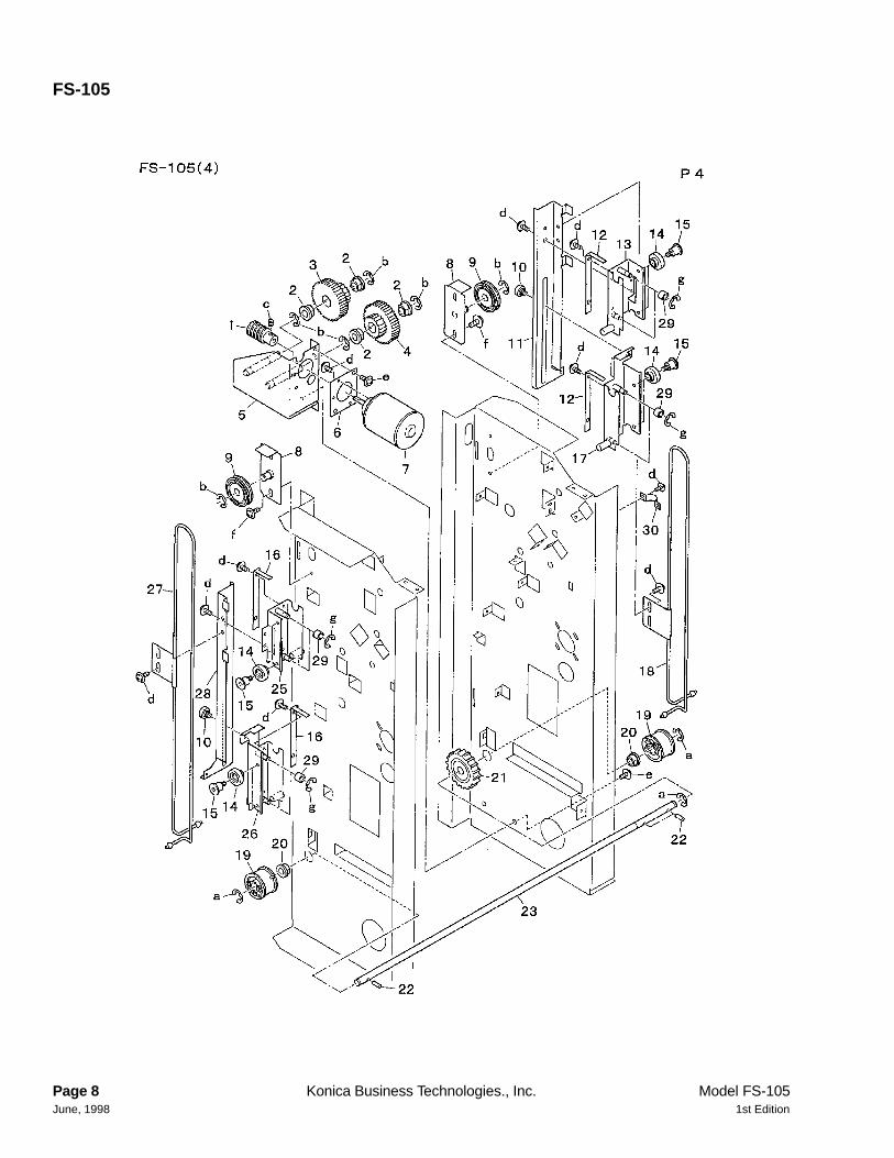
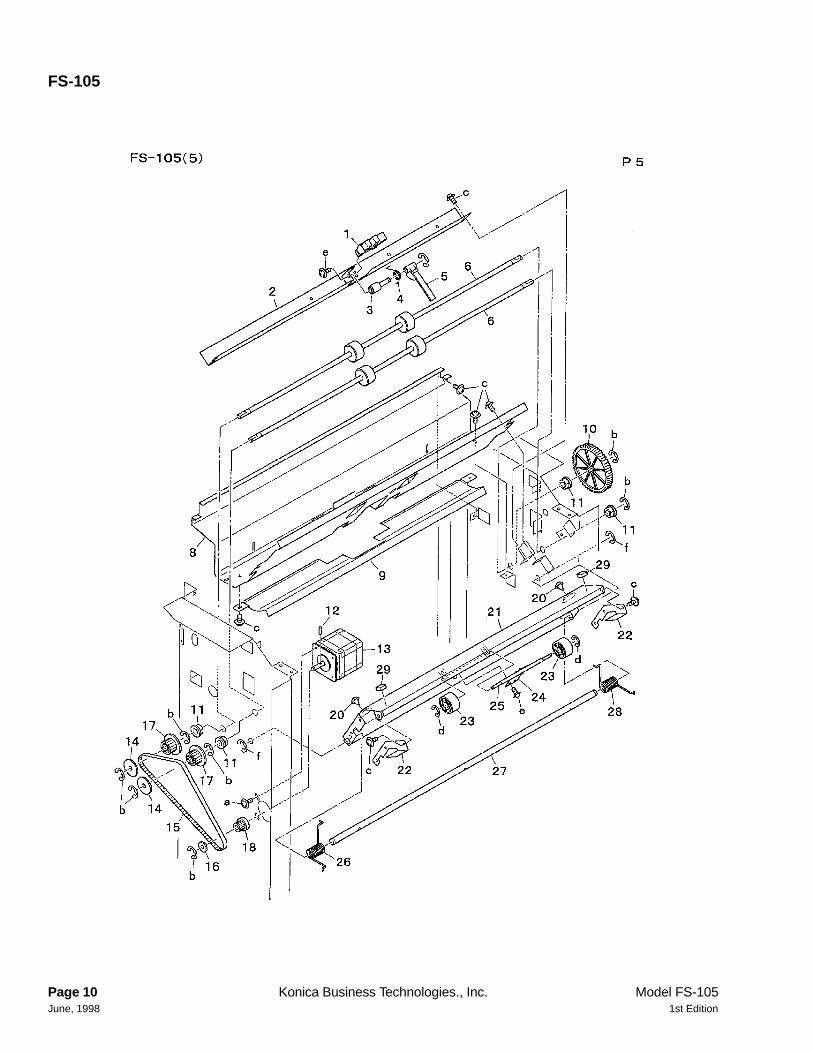
1 12QR77030 Up-down worm2 090075530 Metal3 120H77080 Up-down gear/A (Z=44/28)4 120H77090 Up-down gear/B (Z=45/14)5 120H-1820 Unit6 120H18040 Motor MT plate7 120H80010 FNS driving motor/18 12QR-4820 Tension plate ass’y9 12QR48270 Tension pulley
10 120H48110 Paper exit up-down spring11 120H48300 Paper exit lift-up rail/rear12 120H48170 Shaft hold plate/rear13 120H-4900 Paper exit lift-up plate/B ass14 120H48080 Driving guide roller15 120H48070 Driving guide shaft16 120H48160 Shaft hold plate/front17 120H-4920 Paper exit lift-up plate/D ass18 120H18060 Up-down wire/R19 12QR48070 Up-down pulley20 002075580 Oilless metal21 12QR77060 Up-down gear/C (Z=30)22 304078070 Pin C23 120H18020 Up-down shaft/A24 * Not used25 120H-4890 Paper exit lift-up plate/A ass’y26 120H-4910 Paper exit lift-up plate/C ass’y27 120H18050 Up-down wire/F28 120H48290 Paper exit lift-up rail/front29 120H50280 Rotation roller30 12QV10150 Cord holding plate
a 00Z670806
b 00Z670606
c 00Z474043d 00Z193061
e 00Z194061
f 00Z164081
g 00Z670406
HARDWAREREF.LTR.
PARTNUMBER
REF. PART NUMBER DESCRIPTIONNO.
Model FS-105 Konica Business Technologies., Inc. Page 91st Edition June, 1998
FS-105
Page 10 Konica Business Technologies., Inc. Model FS-105June, 1998 1st Edition
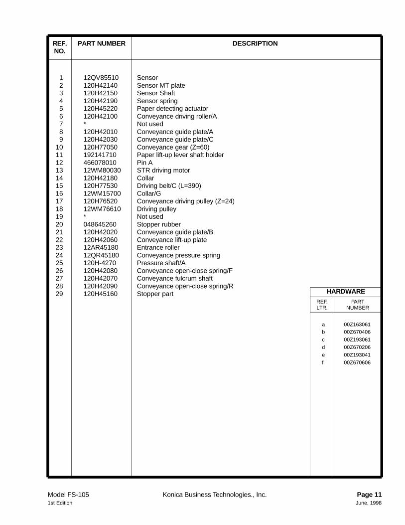
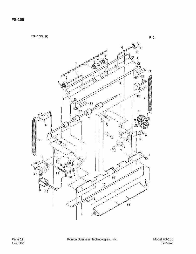
1 12QV85510 Sensor2 120H42140 Sensor MT plate3 120H42150 Sensor Shaft4 120H42190 Sensor spring5 120H45220 Paper detecting actuator6 120H42100 Conveyance driving roller/A7 * Not used8 120H42010 Conveyance guide plate/A9 120H42030 Conveyance guide plate/C
10 120H77050 Conveyance gear (Z=60)11 192141710 Paper lift-up lever shaft holder12 466078010 Pin A13 12WM80030 STR driving motor14 120H42180 Collar15 120H77530 Driving belt/C (L=390)16 12WM15700 Collar/G17 120H76520 Conveyance driving pulley (Z=24)18 12WM76610 Driving pulley19 * Not used20 048645260 Stopper rubber21 120H42020 Conveyance guide plate/B22 120H42060 Conveyance lift-up plate23 12AR45180 Entrance roller24 12QR45180 Conveyance pressure spring25 120H-4270 Pressure shaft/A26 120H42080 Conveyance open-close spring/F27 120H42070 Conveyance fulcrum shaft28 120H42090 Conveyance open-close spring/R29 120H45160 Stopper part
a 00Z163061b 00Z670406
c 00Z193061
d 00Z670206
e 00Z193041
f 00Z670606
HARDWAREREF.LTR.
PARTNUMBER
REF. PART NUMBER DESCRIPTIONNO.
Model FS-105 Konica Business Technologies., Inc. Page 111st Edition June, 1998
FS-105
Page 12 Konica Business Technologies., Inc. Model FS-105June, 1998 1st Edition
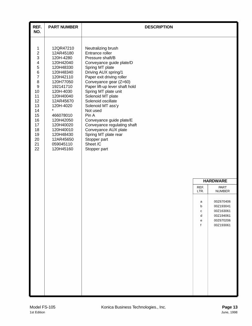
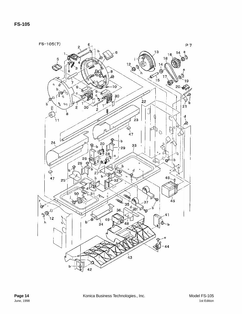
1 12QR47210 Neutralizing brush2 12AR45180 Entrance roller3 120H-4280 Pressure shaft/B4 120H42040 Conveyance guide plate/D5 120H48330 Spring MT plate6 120H48340 Driving AUX spring/17 120H42110 Paper exit driving roller8 120H77050 Conveyance gear (Z=60)9 192141710 Paper lift-up lever shaft hold
10 120H-4030 Spring MT plate unit11 120H40040 Solenoid MT plate12 12AR45670 Solenoid oscillate13 120H-4020 Solenoid MT ass’y14 * Not used15 466078010 Pin A16 120H42050 Conveyance guide plate/E17 120H40020 Conveyance regulating shaft18 120H40010 Conveyance AUX plate19 120H48430 Spring MT plate rear20 12AR45650 Stopper part21 059045110 Sheet /C22 120H45160 Stopper part
a 00Z670406b 00Z193041
c 00Z163061
d 00Z194061
e 00Z670206
f 00Z193061
HARDWAREREF.LTR.
PARTNUMBER
REF. PART NUMBER DESCRIPTIONNO.
Model FS-105 Konica Business Technologies., Inc. Page 131st Edition June, 1998
FS-105
Page 14 Konica Business Technologies., Inc. Model FS-105June, 1998 1st Edition
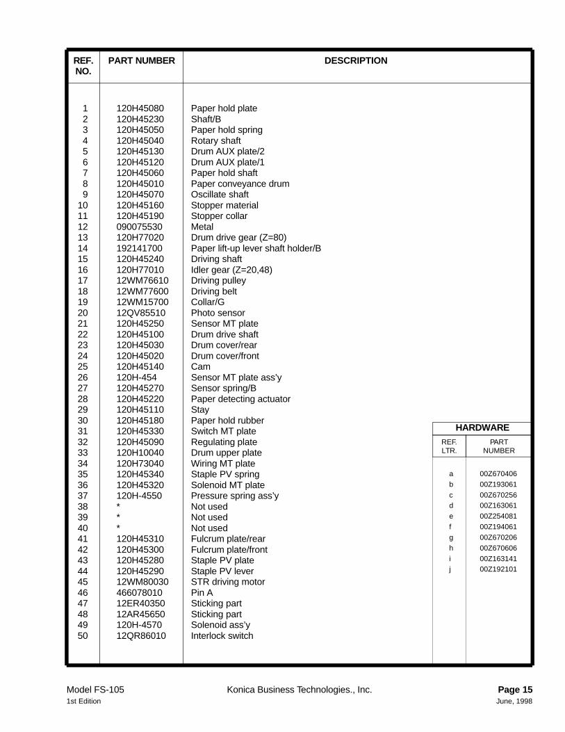
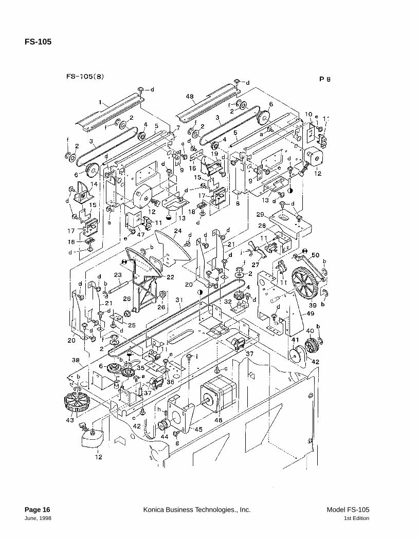
1 120H45080 Paper hold plate2 120H45230 Shaft/B3 120H45050 Paper hold spring4 120H45040 Rotary shaft5 120H45130 Drum AUX plate/26 120H45120 Drum AUX plate/17 120H45060 Paper hold shaft8 120H45010 Paper conveyance drum9 120H45070 Oscillate shaft
10 120H45160 Stopper material11 120H45190 Stopper collar12 090075530 Metal13 120H77020 Drum drive gear (Z=80)14 192141700 Paper lift-up lever shaft holder/B15 120H45240 Driving shaft16 120H77010 Idler gear (Z=20,48)17 12WM76610 Driving pulley18 12WM77600 Driving belt19 12WM15700 Collar/G20 12QV85510 Photo sensor21 120H45250 Sensor MT plate22 120H45100 Drum drive shaft23 120H45030 Drum cover/rear24 120H45020 Drum cover/front25 120H45140 Cam26 120H-454 Sensor MT plate ass’y27 120H45270 Sensor spring/B28 120H45220 Paper detecting actuator29 120H45110 Stay30 120H45180 Paper hold rubber31 120H45330 Switch MT plate32 120H45090 Regulating plate33 120H10040 Drum upper plate34 120H73040 Wiring MT plate35 120H45340 Staple PV spring36 120H45320 Solenoid MT plate37 120H-4550 Pressure spring ass’y38 * Not used39 * Not used40 * Not used41 120H45310 Fulcrum plate/rear42 120H45300 Fulcrum plate/front43 120H45280 Staple PV plate44 120H45290 Staple PV lever45 12WM80030 STR driving motor46 466078010 Pin A47 12ER40350 Sticking part48 12AR45650 Sticking part49 120H-4570 Solenoid ass’y50 12QR86010 Interlock switch
a 00Z670406
b 00Z193061
c 00Z670256d 00Z163061
e 00Z254081
f 00Z194061
g 00Z670206
h 00Z670606
i 00Z163141j 00Z192101
HARDWAREREF.LTR.
PARTNUMBER
REF. PART NUMBER DESCRIPTIONNO.
Model FS-105 Konica Business Technologies., Inc. Page 151st Edition June, 1998
FS-105
Page 16 Konica Business Technologies., Inc. Model FS-105June, 1998 1st Edition
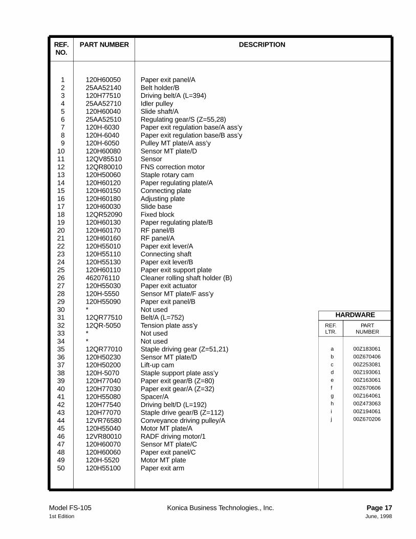
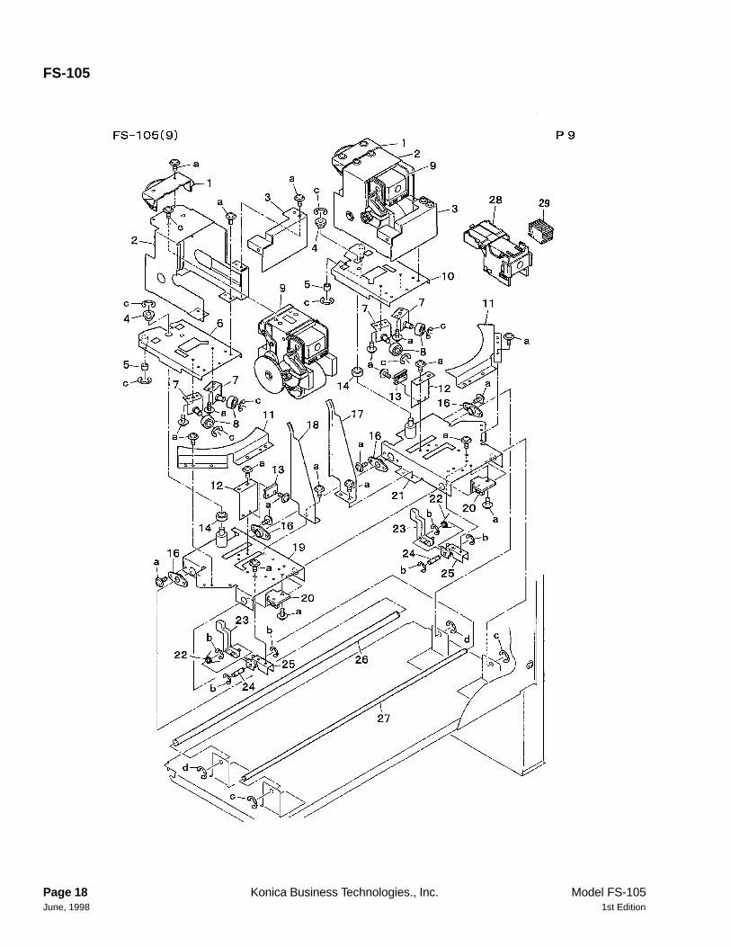
1 120H60050 Paper exit panel/A2 25AA52140 Belt holder/B3 120H77510 Driving belt/A (L=394)4 25AA52710 Idler pulley5 120H60040 Slide shaft/A6 25AA52510 Regulating gear/S (Z=55,28)7 120H-6030 Paper exit regulation base/A ass’y8 120H-6040 Paper exit regulation base/B ass’y9 120H-6050 Pulley MT plate/A ass’y
10 120H60080 Sensor MT plate/D11 12QV85510 Sensor12 12QR80010 FNS correction motor13 120H50060 Staple rotary cam14 120H60120 Paper regulating plate/A15 120H60150 Connecting plate16 120H60180 Adjusting plate17 120H60030 Slide base18 12QR52090 Fixed block19 120H60130 Paper regulating plate/B20 120H60170 RF panel/B21 120H60160 RF panel/A22 120H55010 Paper exit lever/A23 120H55110 Connecting shaft24 120H55130 Paper exit lever/B25 120H60110 Paper exit support plate26 462076110 Cleaner rolling shaft holder (B)27 120H55030 Paper exit actuator28 120H-5550 Sensor MT plate/F ass’y29 120H55090 Paper exit panel/B30 * Not used31 12QR77510 Belt/A (L=752)32 12QR-5050 Tension plate ass’y33 * Not used34 * Not used35 12QR77010 Staple driving gear (Z=51,21)36 120H50230 Sensor MT plate/D37 120H50200 Lift-up cam38 120H-5070 Staple support plate ass’y39 120H77040 Paper exit gear/B (Z=80)40 120H77030 Paper exit gear/A (Z=32)41 120H55080 Spacer/A42 120H77540 Driving belt/D (L=192)43 120H77070 Staple drive gear/B (Z=112)44 12VR76580 Conveyance driving pulley/A45 120H55040 Motor MT plate/A46 12VR80010 RADF driving motor/147 120H60070 Sensor MT plate/C48 120H60060 Paper exit panel/C49 120H-5520 Motor MT plate50 120H55100 Paper exit arm
a 00Z183061
b 00Z670406
c 00Z253081d 00Z193061
e 00Z163061
f 00Z670606
g 00Z164061
h 00Z473063
i 00Z194061j 00Z670206
HARDWAREREF.LTR.
PARTNUMBER
REF. PART NUMBER DESCRIPTIONNO.
Model FS-105 Konica Business Technologies., Inc. Page 171st Edition June, 1998
FS-105
Page 18 Konica Business Technologies., Inc. Model FS-105June, 1998 1st Edition
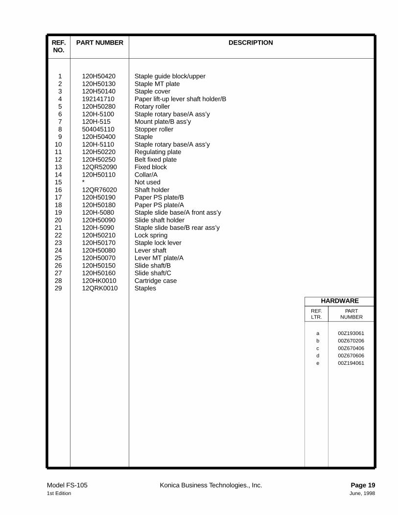
1 120H50420 Staple guide block/upper2 120H50130 Staple MT plate3 120H50140 Staple cover4 192141710 Paper lift-up lever shaft holder/B5 120H50280 Rotary roller6 120H-5100 Staple rotary base/A ass’y7 120H-515 Mount plate/B ass’y8 504045110 Stopper roller9 120H50400 Staple
10 120H-5110 Staple rotary base/A ass’y11 120H50220 Regulating plate12 120H50250 Belt fixed plate13 12QR52090 Fixed block14 120H50110 Collar/A15 * Not used16 12QR76020 Shaft holder17 120H50190 Paper PS plate/B18 120H50180 Paper PS plate/A19 120H-5080 Staple slide base/A front ass’y20 120H50090 Slide shaft holder21 120H-5090 Staple slide base/B rear ass’y22 120H50210 Lock spring23 120H50170 Staple lock lever24 120H50080 Lever shaft25 120H50070 Lever MT plate/A26 120H50150 Slide shaft/B27 120H50160 Slide shaft/C28 120HK0010 Cartridge case29 12QRK0010 Staples
a 00Z193061
b 00Z670206
c 00Z670406d 00Z670606
e 00Z194061
HARDWAREREF.LTR.
PARTNUMBER
REF. PART NUMBER DESCRIPTIONNO.
Model FS-105 Konica Business Technologies., Inc. Page 191st Edition June, 1998
Wiring
Page 20 Konica Business Technologies., Inc. Model FS-105June, 1998 1st Edition

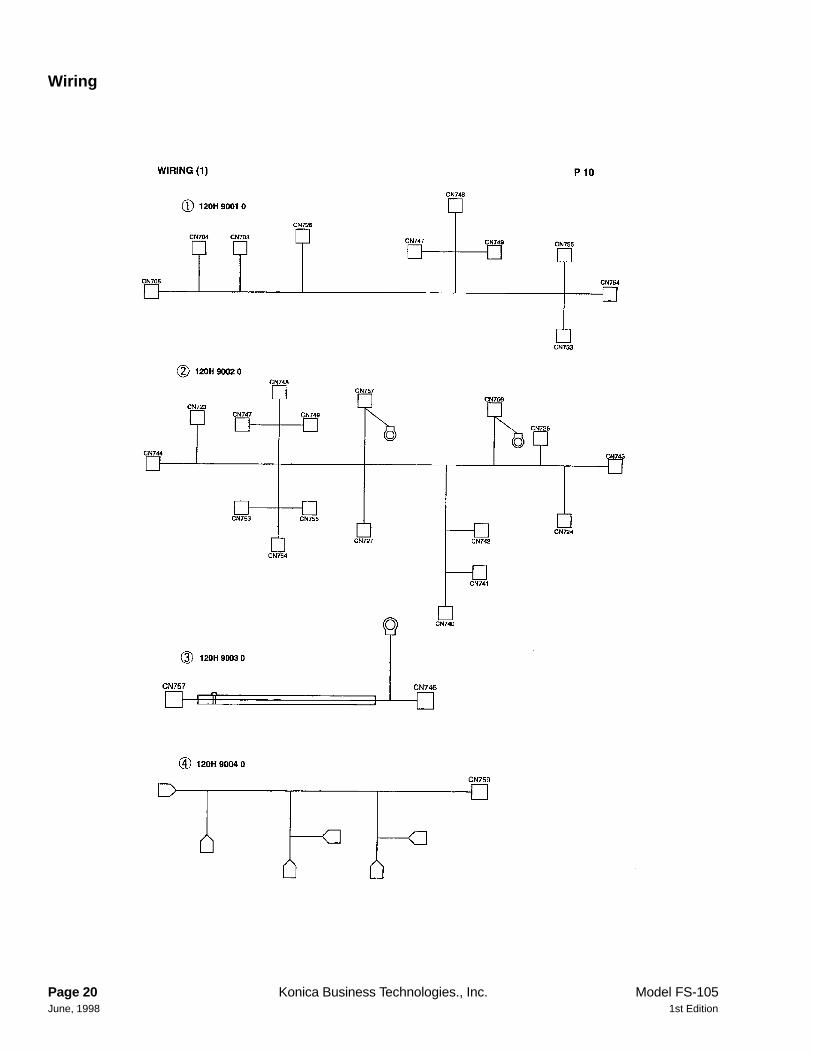
1 120H90010 FNS wiring/12 120H90020 FNS wiring/23 120H90030 Relay wiring/14 120H90040 Interlock wiring/3
REF. PART NUMBER DESCRIPTIONNO.
Model FS-105 Konica Business Technologies., Inc. Page 211st Edition June, 1998
Wiring
Page 22 Konica Business Technologies., Inc. Model FS-105June, 1998 1st Edition
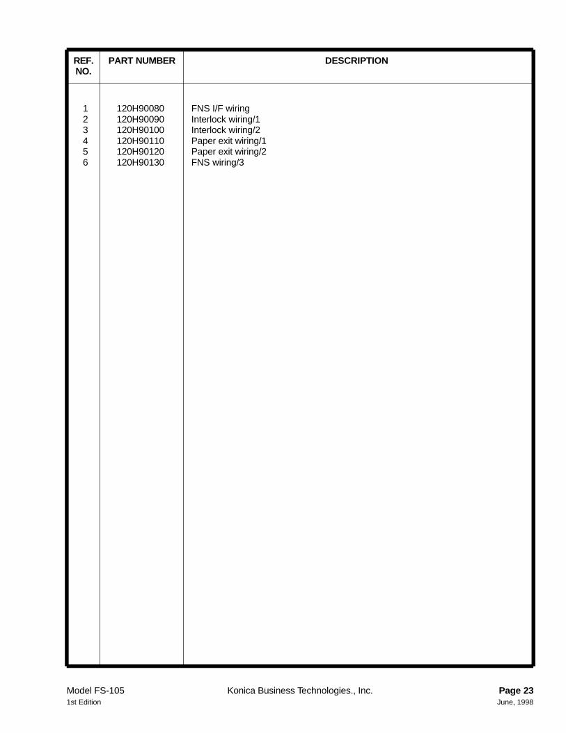
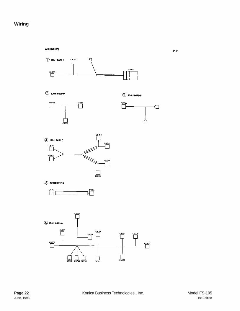
1 120H90080 FNS I/F wiring2 120H90090 Interlock wiring/13 120H90100 Interlock wiring/24 120H90110 Paper exit wiring/15 120H90120 Paper exit wiring/26 120H90130 FNS wiring/3
REF. PART NUMBER DESCRIPTIONNO.
Model FS-105 Konica Business Technologies., Inc. Page 231st Edition June, 1998

This page left blank intentionally.
Page 24 Konica Business Technologies, Inc. Model DF-311June, 1998 1st Edition
AActuator . . . . . . . . . . 3 9Adjusting plate . . . . . . . 17 16
BBelt fixed plate . . . . . . . 19 12Belt holder/B . . . . . . . . 17 2Belt/A (L=752) . . . . . . . 17 31Bottom plate . . . . . . . . 3 13
CCam . . . . . . . . . . . . 15 25Carriage cover . . . . . . . 3 14Carriage fixed plate . . . . 3 21Carriage fulcrum shaft . . . 3 27Carriage rail . . . . . . . . 3 22Carriage stay . . . . . . . . 3 30Carriage support material/A 3 19Carriage support material/B 3 18Carriage support plate/front 3 24Carriage support plate/rear 3 26Cartridge case . . . . . . . 19 28Cleaner rolling shaft holder
(B) . . . . . . . . . . . 17 26Collar . . . . . . . . . . . . 11 14Collar/A . . . . . . . . . . 19 14Collar/G . . . . . . . . . . 11 16Collar/G . . . . . . . . . . 15 19Connecting plate . . . . . . 7 22Connecting plate . . . . . . 17 15Connecting plate/front ass’y 3 28Connecting plate/rear ass’y 3 29Connecting shaft . . . . . . 17 23Conveyance AUX collar . . 5 8Conveyance AUX plate . . . 13 18Conveyance driving pulley
(Z=24) . . . . . . . . . 11 17Conveyance driving pulley/A 17 44Conveyance driving roller/A 11 6Conveyance fulcrum shaft . 11 27Conveyance gear (Z=60) . . 11 10Conveyance gear (Z=60) . . 13 8Conveyance guide plate/A . 11 8Conveyance guide plate/B . 11 21Conveyance guide plate/C . 11 9Conveyance guide plate/D . 13 4Conveyance guide plate/E . 13 16Conveyance lift-up plate . . 11 22Conveyance open-close
spring/F . . . . . . . . 11 26Conveyance open-close
spring/R . . . . . . . . 11 28Conveyance pressure spring 11 24Conveyance regulating shaft 13 17Cord holding plate . . . . . 3 31Cord holding plate . . . . . 9 30
DDesk roller/R . . . . . . . . 3 20Detecting plate/upper . . . 7 1Driving AUX spring/1 . . . . 13 6Driving MT plate ass’y . . . 5 20Driving belt . . . . . . . . . 15 18Driving belt/A (L=394) . . . 17 3Driving belt/C (L=390) . . . 11 15Driving belt/D (L=192) . . . 17 42Driving guide roller . . . . . 9 14Driving guide shaft . . . . . 9 15Driving pulley . . . . . . . . 11 18Driving pulley . . . . . . . . 15 17Driving shaft . . . . . . . . 15 15Drum AUX plate/1 . . . . . 15 6Drum AUX plate/2 . . . . . 15 5Drum cover/front . . . . . . 15 24Drum cover/rear . . . . . . 15 23Drum drive gear (Z=80) . . 15 13Drum drive shaft . . . . . . 15 22Drum upper plate . . . . . . 15 33
EElectrical parts MT plate . . 3 4Entrance pressure spring . 7 8Entrance roller . . . . . . . 11 23Entrance roller . . . . . . . 13 2
FFNS I/F wiring . . . . . . . 23 1FNS control board . . . . . 3 5FNS correction motor . . . 5 16FNS correction motor . . . 17 12FNS driving motor/1 . . . . 9 7FNS wiring/1 . . . . . . . . 21 1FNS wiring/2 . . . . . . . . 21 2FNS wiring/3 . . . . . . . . 23 6Fixed block . . . . . . . . . 17 18Fixed block . . . . . . . . . 19 13Front cover . . . . . . . . . 5 23Fulcrum plate/front . . . . . 15 42Fulcrum plate/rear . . . . . 15 41Fulcrum shaft/A . . . . . . 7 19Fulcrum shaft/B . . . . . . 7 27
HHinge guide plate . . . . . . 7 15
IIdler gear (Z=20/48) . . . . 15 16Idler pulley . . . . . . . . . 17 4Interlock switch . . . . . . . 3 10Interlock switch . . . . . . . 7 12Interlock switch . . . . . . . 15 50Interlock wiring/1 . . . . . . 23 2
Interlock wiring/2 . . . . . . 23 3Interlock wiring/3 . . . . . . 21 4
LLever MT plate . . . . . . . 7 14Lever MT plate/A . . . . . . 19 25Lever fulcrum shaft . . . . . 7 17Lever release plate/A ass’y . 7 18Lever shaft . . . . . . . . . 19 24Lift-up cam . . . . . . . . . 17 37Lock spring . . . . . . . . . 19 22
MMain body fixed plate . . . . 3 16Main body lock plate . . . . 7 24Main body lock shaft . . . . 7 25Main body regulating stopper 3 23Main body stopper . . . . . 3 25Metal . . . . . . . . . . . . 9 2Metal . . . . . . . . . . . . 15 12Motor MT plate . . . . . . . 9 6Motor MT plate . . . . . . . 17 49Motor MT plate/A . . . . . . 17 45Mount plate/B ass’y . . . . . 19 7
NNeutralizing brush . . . . . 13 1
OOilless metal . . . . . . . . 9 20Open-close spring . . . . . 7 20Oscillate shaft . . . . . . . . 15 9
PPaper PS plate/A . . . . . . 19 18Paper PS plate/B . . . . . . 19 17Paper conveyance drum . . 15 8Paper detecting actuator . . 7 7Paper detecting actuator . . 11 5Paper detecting actuator . . 15 28Paper exit AUX shaft . . . . 5 13Paper exit actuator . . . . . 17 27Paper exit arm . . . . . . . 17 50Paper exit driving cover . . . 5 17Paper exit driving gear (Z=26) 5 19Paper exit driving rail/front . 3 3Paper exit driving rail/rear . 3 7Paper exit driving roller . . . 13 7Paper exit gear/A (Z=32) . . 17 40Paper exit gear/B (Z=80) . . 17 39Paper exit idler gear (Z=75) . 5 15Paper exit lever/A . . . . . . 17 22Paper exit lever/B . . . . . . 17 24Paper exit lift-up plate/A ass’y 9 25
PART PAGE REF.DESCRIPTION NO. NO.
PART PAGE REF.DESCRIPTION NO. NO.
PART PAGE REF.DESCRIPTION NO. NO.
Alphabetical index
Model DF-311 Konica Business Technologies, Inc. Page 251st Edition June, 1998
Paper exit lift-up plate/B ass 9 13Paper exit lift-up plate/C ass 9 26Paper exit lift-up plate/D ass 9 17Paper exit lift-up rail/front . . 9 28Paper exit lift-up rail/rear . . 9 11Paper exit panel/A . . . . . 17 1Paper exit panel/B . . . . . 17 29Paper exit panel/C . . . . . 17 48Paper exit panel/D . . . . . 7 26Paper exit protection cam . . 7 28Paper exit regulation base/A
ass’y . . . . . . . . . . 17 7Paper exit regulation base/B
ass’y . . . . . . . . . . 17 8Paper exit roller/A . . . . . . 5 7Paper exit support plate . . . 17 25Paper exit support plate/front 5 3Paper exit support plate/rear 5 5Paper exit tray/A . . . . . . 5 1Paper exit tray/B . . . . . . 5 2Paper exit up-down spring . 9 10Paper exit wiring . . . . . . 5 24Paper exit wiring/1 . . . . . 23 4Paper exit wiring/2 . . . . . 23 5Paper hold plate . . . . . . 15 1Paper hold rubber . . . . . . 15 30Paper hold shaft . . . . . . 15 7Paper hold spring . . . . . . 15 3Paper lift-up lever shaft
holder . . . . . . . . . . 11 11Paper lift-up lever shaft
holder . . . . . . . . . . 13 9Paper lift-up lever shaft
holder/B . . . . . . . . 15 14Paper lift-up lever shaft
holder/B . . . . . . . . 19 4Paper lift-up shaft holder . . 5 18Paper regulating plate/A . . 17 14Paper regulating plate/B . . 17 19Photo sensor . . . . . . . . 15 20Pin A . . . . . . . . . . . . 11 12Pin A . . . . . . . . . . . . 13 15Pin A . . . . . . . . . . . . 15 46Pin C . . . . . . . . . . . . 9 22Pin (cleaner A) . . . . . . . 5 14Pressure shaft/A . . . . . . 11 25Pressure shaft/B . . . . . . 13 3Pressure spring ass’y . . . . 15 37Pulley MT plate/A ass’y . . . 17 9
RRADF driving motor/1 . . . . 17 46RF panel/A . . . . . . . . . 17 21RF panel/B . . . . . . . . . 17 20RF stay . . . . . . . . . . . 7 9Rear AUX cover . . . . . . . 5 25Rear cover . . . . . . . . . 5 22Rear plate . . . . . . . . . . 3 17
Regulating gear/S (Z=55,28) 17 6Regulating plate . . . . . . 15 32Regulating plate . . . . . . 19 11Relay wiring/1 . . . . . . . 21 3Release lever . . . . . . . 7 13Rocking part ass’y . . . . 7 23Rotary roller . . . . . . . . 19 5Rotary shaft . . . . . . . . 15 4Rotation roller . . . . . . . 9 29
SSTR driving motor . . . . . 11 13STR driving motor . . . . . 15 45Sensor . . . . . . . . . . 5 12Sensor . . . . . . . . . . 7 3Sensor . . . . . . . . . . 11 1Sensor . . . . . . . . . . 17 11Sensor MT plate . . . . . 3 11Sensor MT plate . . . . . 5 11Sensor MT plate . . . . . 7 4Sensor MT plate . . . . . 11 2Sensor MT plate . . . . . 15 21Sensor MT plate ass’y . . 15 26Sensor MT plate/A . . . . 7 10Sensor MT plate/C . . . . 17 47Sensor MT plate/D . . . . 17 10Sensor MT plate/D . . . . 17 36Sensor MT plate/F ass’y . 17 28Sensor shaft . . . . . . . . 7 5Sensor shaft . . . . . . . . 11 3Sensor protect plate/A . . 5 10Sensor spring . . . . . . . 11 4Sensor spring/A . . . . . . 7 6Sensor spring/B . . . . . . 15 27Shaft hold plate/front . . . 9 16Shaft hold plate/rear . . . 9 12Shaft holder . . . . . . . . 19 16Shaft holder(B) . . . . . . 5 9Shaft/B . . . . . . . . . . 15 2Sheet /C . . . . . . . . . . 13 21Side cover/right . . . . . . 3 15Slide base . . . . . . . . . 17 17Slide shaft holder . . . . . 19 20Slide shaft/A . . . . . . . . 17 5Slide shaft/B . . . . . . . . 19 26Slide shaft/C . . . . . . . 19 27Solenoid MT ass’y . . . . . 13 13Solenoid MT plate . . . . . 13 11Solenoid MT plate . . . . . 15 36Solenoid ass’y . . . . . . . 15 49Solenoid oscillate . . . . . 13 12Spacer/A . . . . . . . . . 17 41Spring MT plate . . . . . . 13 5Spring MT plate rear . . . 13 19Spring MT plate unit . . . . 13 10Spring support plate . . . 5 4Staple . . . . . . . . . . . 19 9Staple MT plate . . . . . . 19 2
Staple PV lever . . . . . . 15 44Staple PV plate . . . . . . 15 43Staple PV spring . . . . . . 15 35Staple cover . . . . . . . . 19 3Staple drive gear/B (Z=112) 17 43Staple driving gear (Z=51,21) 17 35Staple guide block/upper . 19 1Staple lock lever . . . . . . 19 23Staple rotary base/A ass’y . 19 6Staple rotary base/A ass’y . 19 10Staple rotary cam . . . . . 17 13Staple slide base/A front
ass’y . . . . . . . . . . 19 19Staple slide base/B rear ass’y 19 21Staple support plate ass’y . 17 38Staples . . . . . . . . . . 19 29Stay . . . . . . . . . . . . 15 29Sticking part . . . . . . . . 15 47Sticking part . . . . . . . . 15 48Stopper collar . . . . . . . 15 11Stopper material . . . . . . 15 10Stopper part . . . . . . . . 7 16Stopper part . . . . . . . . 11 29Stopper part . . . . . . . . 13 20Stopper part . . . . . . . . 13 22Stopper roller . . . . . . . 19 8Stopper rubber . . . . . . 11 20Support panel/left . . . . . 3 1Support spring . . . . . . . 5 6Switch MT plate . . . . . . 15 31Switch input material . . . 7 2
TTension plate ass’y . . . . 9 8Tension plate ass’y . . . . 17 32Tension pulley . . . . . . . 9 9
UUnit . . . . . . . . . . . . 9 5Up-down gear/A (Z=44/28) 9 3Up-down gear/B (Z=45/14) 9 4Up-down gear/C (Z=30) . . 9 21Up-down pulley . . . . . . 9 19Up-down shaft/A . . . . . . 9 23Up-down wire/F . . . . . . 9 27Up-down wire/R . . . . . . 9 18Up-down worm . . . . . . 9 1Upper plate . . . . . . . . 5 21
WWiring MT base . . . . . . 7 11Wiring MT plate . . . . . . 15 34
PART PAGE REF.DESCRIPTION NO. NO.
PART PAGE REF.DESCRIPTION NO. NO.
PART PAGE REF.DESCRIPTION NO. NO.
Page 26 Konica Business Technologies, Inc. Model DF-311June, 1998 1st Edition

This page left blank intentionally.
Page 26 Konica Business Technologies, Inc. Model FS-105June, 1998 1st Edition
002075580 . . . . 9 20048645260 . . . . 11 20049810020 . . . . 3 20059045110 . . . . 13 21090075530 . . . . 9 2090075530 . . . . 15 12120H-1140 . . . . 7 18120H-1820 . . . . 9 5120H-2050 . . . . 3 28120H-2060 . . . . 3 29120H-4020 . . . . 13 13120H-4030 . . . . 13 10120H-4270 . . . . 11 25120H-4280 . . . . 13 3120H-454 . . . . 15 26120H-4550 . . . . 15 37120H-4570 . . . . 15 49120H-4830 . . . . 5 3120H-4840 . . . . 5 5120H-4890 . . . . 9 25120H-4900 . . . . 9 13120H-4910 . . . . 9 26120H-4920 . . . . 9 17120H-4960 . . . . 5 20120H-5070 . . . . 17 38120H-5080 . . . . 19 19120H-5090 . . . . 19 21120H-5100 . . . . 19 6120H-5110 . . . . 19 10120H-515 . . . . 19 7120H-5520 . . . . 17 49120H-5550 . . . . 17 28120H-6030 . . . . 17 7120H-6040 . . . . 17 8120H-6050 . . . . 17 9120H-9010 . . . . 3 5120H10030 . . . 3 13120H10040 . . . 15 33120H10050 . . . 3 1120H10060 . . . 3 15120H10070 . . . 3 16120H10080 . . . 7 25120H10090 . . . 7 24120H10120 . . . 7 22120H10130 . . . 7 14120H10140 . . . 7 15120H10150 . . . 7 17120H10160 . . . 7 1120H10170 . . . 7 20120H10180 . . . 7 28120H10190 . . . 7 19120H10200 . . . 7 27120H10210 . . . 7 26120H10230 . . . 7 2120H12010 . . . 5 23120H12020 . . . 5 22120H12030 . . . 5 21120H12040 . . . 5 25120H12110 . . . 7 13120H18020 . . . 9 23120H18040 . . . 9 6120H18050 . . . 9 27120H18060 . . . 9 18120H20010 . . . 3 24
120H20020 . . . . 3 26120H20030 . . . . 3 21120H20040 . . . . 3 22120H20050 . . . . 3 14120H20060 . . . . 3 27120H20070 . . . . 3 30120H20080 . . . . 3 25120H20090 . . . . 3 23120H20130 . . . . 3 19120H20140 . . . . 3 18120H40010 . . . . 13 18120H40020 . . . . 13 17120H40040 . . . . 13 11120H42010 . . . . 11 8120H42020 . . . . 11 21120H42030 . . . . 11 9120H42040 . . . . 13 4120H42050 . . . . 13 16120H42060 . . . . 11 22120H42070 . . . . 11 27120H42080 . . . . 11 26120H42090 . . . . 11 28120H42100 . . . . 11 6120H42110 . . . . 13 7120H42140 . . . . 11 2120H42150 . . . . 7 5120H42150 . . . . 11 3120H42160 . . . . 7 9120H42170 . . . . 7 4120H42180 . . . . 11 14120H42190 . . . . 7 6120H42190 . . . . 11 4120H42200 . . . . 7 7120H45010 . . . . 15 8120H45020 . . . . 15 24120H45030 . . . . 15 23120H45040 . . . . 15 4120H45050 . . . . 15 3120H45060 . . . . 15 7120H45070 . . . . 15 9120H45080 . . . . 15 1120H45090 . . . . 15 32120H45100 . . . . 15 22120H45110 . . . . 15 29120H45120 . . . . 15 6120H45130 . . . . 15 5120H45140 . . . . 15 25120H45160 . . . . 11 29120H45160 . . . . 13 22120H45160 . . . . 15 10120H45180 . . . . 15 30120H45190 . . . . 15 11120H45220 . . . . 11 5120H45220 . . . . 15 28120H45230 . . . . 15 2120H45240 . . . . 15 15120H45250 . . . . 15 21120H45270 . . . . 15 27120H45280 . . . . 15 43120H45290 . . . . 15 44120H45300 . . . . 15 42120H45310 . . . . 15 41120H45320 . . . . 15 36120H45330 . . . . 15 31
120H45340 . . . . 15 35120H48010 . . . . 5 1120H48020 . . . . 5 2120H48030 . . . . 3 3120H48040 . . . . 3 7120H48050 . . . . 5 4120H48060 . . . . 5 6120H48070 . . . . 9 15120H48080 . . . . 9 14120H48090 . . . . 7 10120H48110 . . . . 9 10120H48160 . . . . 9 16120H48170 . . . . 9 12120H48290 . . . . 9 28120H48300 . . . . 9 11120H48330 . . . . 13 5120H48340 . . . . 13 6120H48360 . . . . 5 13120H48370 . . . . 5 17120H48400 . . . . 5 8120H48410 . . . . 5 11120H48420 . . . . 5 10120H48430 . . . . 13 19120H50060 . . . . 17 13120H50070 . . . . 19 25120H50080 . . . . 19 24120H50090 . . . . 19 20120H50110 . . . . 19 14120H50130 . . . . 19 2120H50140 . . . . 19 3120H50150 . . . . 19 26120H50160 . . . . 19 27120H50170 . . . . 19 23120H50180 . . . . 19 18120H50190 . . . . 19 17120H50200 . . . . 17 37120H50210 . . . . 19 22120H50220 . . . . 19 11120H50230 . . . . 17 36120H50240 . . . . 3 17120H50250 . . . . 19 12120H50280 . . . . 9 29120H50280 . . . . 19 5120H50400 . . . . 19 9120H50420 . . . . 19 1120H55010 . . . . 17 22120H55030 . . . . 17 27120H55040 . . . . 17 45120H55080 . . . . 17 41120H55090 . . . . 17 29120H55100 . . . . 17 50120H55110 . . . . 17 23120H55130 . . . . 17 24120H60030 . . . . 17 17120H60040 . . . . 17 5120H60050 . . . . 17 1120H60060 . . . . 17 48120H60070 . . . . 17 47120H60080 . . . . 17 10120H60110 . . . . 17 25120H60120 . . . . 17 14120H60130 . . . . 17 19120H60150 . . . . 17 15120H60160 . . . . 17 21
PART PAGE REF. SUGGESTEDNUMBER NO. NO. RETAIL
PART PAGE REF. SUGGESTEDNUMBER NO. NO. RETAIL
PART PAGE REF. SUGGESTEDNUMBER NO. NO. RETAIL
Numerical indexRetail price list
Model FS-105 Konica Business Technologies, Inc. Page 271st Edition June, 1998

120H60170 . . . . 17 20120H60180 . . . . 17 16120H73010 . . . . 3 4120H73020 . . . . 3 11120H73030 . . . . 7 11120H73040 . . . . 15 34120H76520 . . . . 11 17120H77010 . . . . 15 16120H77020 . . . . 15 13120H77030 . . . . 17 40120H77040 . . . . 17 39120H77050 . . . . 11 10120H77050 . . . . 13 8120H77070 . . . . 17 43120H77080 . . . . 9 3120H77090 . . . . 9 4120H77120 . . . . 5 15120H77130 . . . . 5 19120H77510 . . . . 17 3120H77530 . . . . 11 15120H77540 . . . . 17 42120H80010 . . . . 9 7120H90010 . . . . 21 1120H90020 . . . . 21 2120H90030 . . . . 21 3120H90040 . . . . 21 4120H90080 . . . . 23 1120H90090 . . . . 23 2120H90100 . . . . 23 3120H90110 . . . . 23 4120H90120 . . . . 5 24120H90120 . . . . 23 5120H90130 . . . . 23 6
120HK0010 . . . . 19 28122H48251 . . . . 5 712AR-4590 . . . . 7 2312AR45131 . . . . 7 812AR45180 . . . . 11 2312AR45180 . . . . 13 212AR45611 . . . . 3 912AR45650 . . . . 7 1612AR45650 . . . . 13 2012AR45650 . . . . 15 4812AR45670 . . . . 13 1212ER40350 . . . . 15 4712QR-4820 . . . . 9 812QR-5050 . . . . 17 3212QR45180 . . . . 11 2412QR47210 . . . . 13 112QR48070 . . . . 9 1912QR48270 . . . . 9 912QR52090 . . . . 17 1812QR52090 . . . . 19 1312QR76020 . . . . 19 1612QR77010 . . . . 17 3512QR77030 . . . . 9 112QR77060 . . . . 9 2112QR77510 . . . . 17 3112QR80010 . . . . 5 1612QR80010 . . . . 17 1212QR86010 . . . . 3 1012QR86010 . . . . 7 1212QR86010 . . . . 15 5012QRK0010 . . . . 19 2912QV10150 . . . . 3 3112QV10150 . . . . 9 30
12QV85510 . . . 5 1212QV85510 . . . 7 312QV85510 . . . 11 112QV85510 . . . 15 2012QV85510 . . . 17 1112VR76580 . . . 17 4412VR80010 . . . 17 4612WM15700 . . . 11 1612WM15700 . . . 15 1912WM76610 . . . 11 1812WM76610 . . . 15 1712WM77600 . . . 15 1812WM80030 . . . 11 1312WM80030 . . . 15 45192141700 . . . 15 14192141710 . . . 5 18192141710 . . . 11 11192141710 . . . 13 9192141710 . . . 19 425AA52140 . . . 17 225AA52510 . . . 17 625AA52710 . . . 17 4300076040 . . . 5 9304078070 . . . 9 22454078050 . . . 5 14462076110 . . . 17 26466078010 . . . 11 12466078010 . . . 13 15466078010 . . . 15 46504045110 . . . 19 8
PART PAGE REF. SUGGESTEDNUMBER NO. NO. RETAIL
PART PAGE REF. SUGGESTEDNUMBER NO. NO. RETAIL
PART PAGE REF. SUGGESTEDNUMBER NO. NO. RETAIL
Page 28 Konica Business Technologies, Inc. Model FS-105June, 1998 1st Edition