koso hammel dahl - laploc · m ansi class 900 (1-1/2”- 6”) n ansi class 1500 (1-1/2”- 6”) 4...
TRANSCRIPT

The V800/V801 Series is a double-seated, top and
bottom guided globe-style valve with screwed-in seat rings.
This style of valve is extremely useful in erosive (dirty) fluids
and systems where high flow rates are required. This valve
style may be ordered as “push stem down to close”
(V800) or “push down to open” (V801) .
CONTROL VALVES
KOSO HAMMEL DAHL
Series V800/V801 Top And Bottom GuidedDouble Seated Globe Valve
1”- 12” (DN25 - 300) ANSI Class 150-1500
B U L L E T I N V 8 0 0 - 1
Specifications
Body Style: Double-seated globe
Body Size: 1" through 12" (DN 25 through 300)
Body Rating: ANSI Class 150, 300, 600, 900, 1500
Body Materials: Carbon steel, Stainless steel and Chrome-moly steel. Other
castable alloys are available upon request.
End Connections: NPT threaded or socket weld (1" through 2"): ANSI flanged
(1" through 12"): ANSI butt weld (2" through 12"). Others available upon request.
Bonnets: Plain, extension and bellows seal
Trim Style: Double-seated semi-balanced contoured trim.
Flow Direction: Up through upper seat ring, and down through lower seat ring
Trim Characteristic: Linear or equal percentage.
Flow Coefficient: Cv from 8 through 1550 (see table 2)
Leakage Class: II
Actuators: Standard bonnet mount will accept spring-diaphragm, piston and
other actuators. For actuator selection, refer to KOSO Hammel Dahl actuator
selection guide.
• Heavy top- and bottom-guiding
assures stable accurate control.
• Reversible body structure allows
"push down to close" or "push down
to open" assembly using the same
parts.
• Contoured trim reduces the effects of
hydraulic side loads on the valve trim.
• "Semi-balanced" design requires
smaller actuator packages than
single-seated valves.
• Full flow design provides approximately
40% more Cv than comparable
single-seated valves.
• Body gaskets are fully captured and
protected from the process medium.
• Optional live-loaded packing.
FEATURES
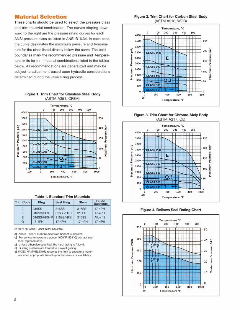
These charts should be used to select the pressure class
and trim material combination. The curves sloping down-
ward to the right are the pressure rating curves for each
ANSI pressure class as listed in ANSI B16.34. In each case,
the curve designates the maximum pressure and tempera-
ture for the class listed directly below the curve. The bold
boundaries mark the recommended pressure and tempera-
ture limits for trim material combinations listed in the tables
below. All recommendations are generalized and may be
subject to adjustment based upon hydraulic considerations
determined during the valve sizing process.
Material Selection
Figure 3. Trim Chart for Chrome-Moly Body(ASTM A217, C5)
Figure 2. Trim Chart for Carbon Steel Body(ASTM A216, WCB)
Figure 1. Trim Chart for Stainless Steel Body(ASTM A351, CF8M)
Figure 4. Bellows Seal Rating Chart
Table 1. Standard Trim Materials Trim Code Plug Seat Ring Stem Guide Bushings
2 316SS 316SS 316SS 17-4PH 3 316SS/HFS 316SS/HFS 316SS 17-4PH E 316SS/HFS+P 316SS/HFS 316SS Alloy 12 Q 17-4PH 17-4PH 17-4PH 17-4PH
NOTES TO TABLE AND TRIM CHARTS
a) Above +600°F (316°C) extension bonnet is requiredb) For service temperature above 1000°F (538°C) contact your
local representative.c) Unless otherwise specified, the hard-facing is Alloy 6.d) Guiding surfaces are treated to prevent galling.e) KOSO HAMMEL DAHL reserves the right to substitute materi-
als when appropriate based upon the service or availability.
2
V 8 0 0 - 1
3
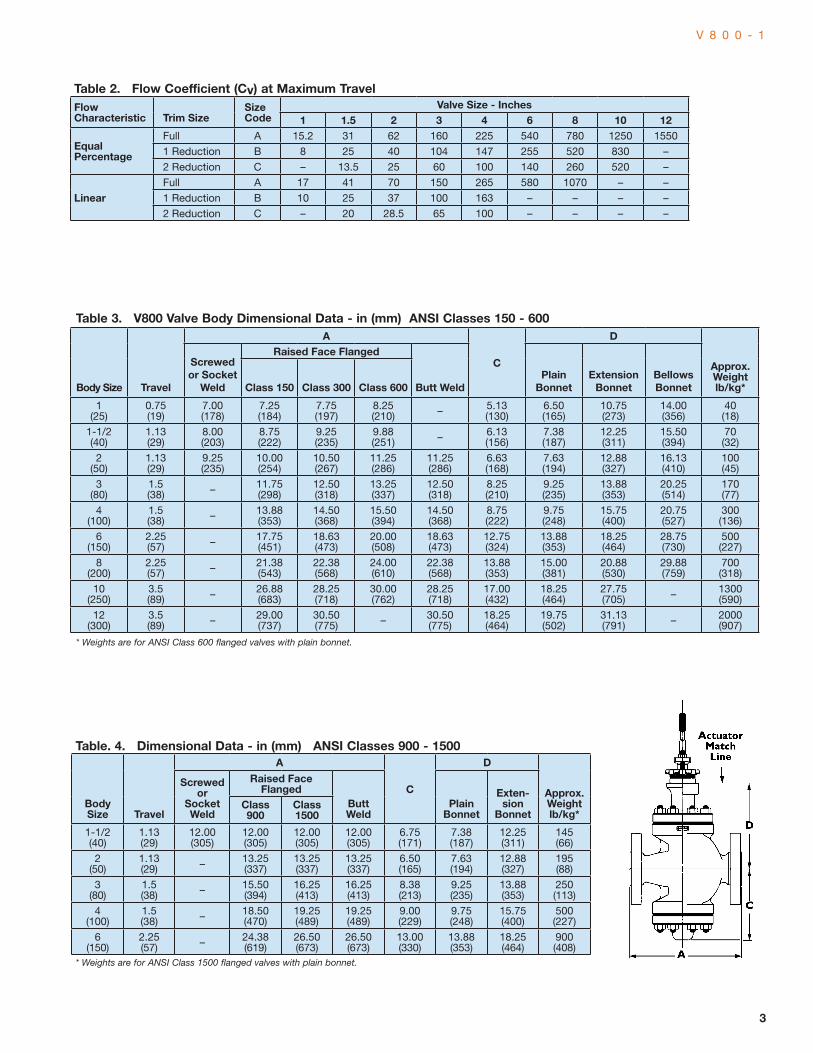
Table. 4. Dimensional Data - in (mm) ANSI Classes 900 - 1500
Body Size Travel
A
C
D
Approx. Weight lb/kg*
Screwed or
Socket Weld
Raised Face Flanged
Butt Weld
Plain Bonnet
Exten-sion
BonnetClass 900
Class 1500
1-1/2 (40)
1.13 (29)
12.00 (305)
12.00 (305)
12.00 (305)
12.00 (305)
6.75 (171)
7.38 (187)
12.25 (311)
145 (66)
2 (50)
1.13 (29) – 13.25
(337)13.25 (337)
13.25 (337)
6.50 (165)
7.63 (194)
12.88 (327)
195 (88)
3 (80)
1.5 (38) – 15.50
(394)16.25 (413)
16.25 (413)
8.38 (213)
9.25 (235)
13.88 (353)
250 (113)
4 (100)
1.5 (38) – 18.50
(470)19.25 (489)
19.25 (489)
9.00 (229)
9.75 (248)
15.75 (400)
500 (227)
6 (150)
2.25 (57) – 24.38
(619)26.50 (673)
26.50 (673)
13.00 (330)
13.88 (353)
18.25 (464)
900 (408)
* Weights are for ANSI Class 1500 flanged valves with plain bonnet.
Table 3. V800 Valve Body Dimensional Data - in (mm) ANSI Classes 150 - 600
Body Size Travel
A
C
D
Approx.Weight lb/kg*
Screwed or Socket
Weld
Raised Face Flanged
Butt WeldPlain
BonnetExtension
BonnetBellows BonnetClass 150 Class 300 Class 600
1 (25)
0.75 (19)
7.00 (178)
7.25 (184)
7.75 (197)
8.25 (210) – 5.13
(130)6.50 (165)
10.75 (273)
14.00 (356)
40 (18)
1-1/2 (40)
1.13 (29)
8.00 (203)
8.75 (222)
9.25 (235)
9.88 (251) – 6.13
(156)7.38 (187)
12.25 (311)
15.50 (394)
70 (32)
2 (50)
1.13 (29)
9.25 (235)
10.00 (254)
10.50 (267)
11.25 (286)
11.25 (286)
6.63 (168)
7.63 (194)
12.88 (327)
16.13 (410)
100 (45)
3 (80)
1.5 (38) – 11.75
(298)12.50 (318)
13.25 (337)
12.50 (318)
8.25 (210)
9.25 (235)
13.88 (353)
20.25 (514)
170 (77)
4 (100)
1.5 (38) – 13.88
(353)14.50 (368)
15.50 (394)
14.50 (368)
8.75 (222)
9.75 (248)
15.75 (400)
20.75 (527)
300 (136)
6 (150)
2.25 (57) – 17.75
(451)18.63 (473)
20.00 (508)
18.63 (473)
12.75 (324)
13.88 (353)
18.25 (464)
28.75 (730)
500 (227)
8 (200)
2.25 (57) – 21.38
(543)22.38 (568)
24.00 (610)
22.38 (568)
13.88 (353)
15.00 (381)
20.88 (530)
29.88 (759)
700 (318)
10 (250)
3.5 (89) – 26.88
(683)28.25 (718)
30.00 (762)
28.25 (718)
17.00 (432)
18.25 (464)
27.75 (705) – 1300
(590)
12 (300)
3.5 (89) – 29.00
(737)30.50 (775) – 30.50
(775)18.25 (464)
19.75 (502)
31.13 (791) – 2000
(907)
* Weights are for ANSI Class 600 flanged valves with plain bonnet.
Table 2. Flow Coefficient (Cv) at Maximum TravelFlow Characteristic Trim Size
Size Code
Valve Size - Inches1 1.5 2 3 4 6 8 10 12
Equal Percentage
Full A 15.2 31 62 160 225 540 780 1250 1550
1 Reduction B 8 25 40 104 147 255 520 830 –
2 Reduction C – 13.5 25 60 100 140 260 520 –
LinearFull A 17 41 70 150 265 580 1070 – –
1 Reduction B 10 25 37 100 163 – – – –
2 Reduction C – 20 28.5 65 100 – – – –
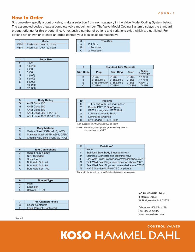
How to OrderTo completely specify a control valve, make a selection from each category in the Valve Model Coding System below. The assembled codes create a complete valve model number. The Valve Model Coding System displays the standard product offering for this product line. An extensive number of options and variations exist, which are not listed. For options not shown or to enter an order, contact your local sales representative.
03/04
KOSO HAMMEL DAHL4 Manley StreetW. Bridgewater, MA 02379
Telephone: 508.584.1199Fax: 508.584.2525www.hammeldahl.com
11 Variations* - None 8 Stainless Steel Body Studs and Nuts 9 Stainless Lubricator and Isolating Valve F Tack Weld Guide Bushings, recommended above 750°F G Tack Weld Seat Rings, recommended above 750°F H Seal Weld Seat Rings, recommended above 750°F N NACE Standard MR-01-75 Compliance*For multiple variations, specify all variation codes required.
V 8 0 0 - 1
KOSO HAMMEL DAHLCONTROL VALVES
1 Model V800 Push stem down to close V801 Push stem down to open
2 Body Size F 1 (25) H 1.5 (40) J 2 (50) L 3 (80) N 4 (100) Q 6 (150) S 8 (200) T 10 (250) U 12 (300)
3 Body Rating G ANSI Class 150 H ANSI Class 300 F ANSI Class 600 M ANSI Class 900 (1-1/2”- 6”) N ANSI Class 1500 (1-1/2”- 6”)
4 Body Material C Carbon Steel (ASTM A216, WCB) E Stainless Steel (ASTM A351, CF8M) K Chrome-Moly Steel (ASTM A217, C5)
5 End Connections 3 Raised Face Flange 4 NPT Threaded 6 Socket Weld 8 Butt Weld Sch. 40 9 Butt Weld Sch. 80 A Butt Weld Sch. 160
6 Bonnet Type 2 Plain 3 Extension 5 Bellows (1”- 8”)
7 Trim Characteristics C Linear, Contoured E Equal Percent, Contoured
8 Trim Size A Full Size B 1 Reduction C 2 Reduction
Trim Code Plug Seat Ring Stem Guide Bushings 2 316SS 316SS 316SS 17-4PH 3 316SS/HFS 316SS/HFS 316SS 17-4PH E 316SS/HFS+P 316SS/HFS 316SS Alloy 12 Q 17-4PH 17-4PH 17-4PH 17-4PH
9 Standard Trim Materials
10 Packing G TFE V-ring with Packing Spacer Y Double PTFE V-Ring/Spacer U PTFE impregnated PTFE Braid W Lubricated Aramid Braid 9 Laminated Graphite B Live-loaded PTFE V-Ring*
*Not available in ANSI Class 900 or 1500
NOTE: Graphite packings are generally required in services above 450°F