kp - content.assaabloyusa.com.pdf · kp series kepad ortise ock general description the sargent kp...
TRANSCRIPT
A7373D
07/18
Copyright 2018, Sargent Manufacturing Company, an ASSA ABLOY Group company. All rights reserved. Reproduction in whole or in part without the express written permission of Sargent Manufacturing Company is prohibited.
KP Series Keypad Mortise LockInstallation & Programming Instructions
KP

Warning
1-800-810-WIRE • www.sargentlock.com • A7373D
Cop
yrig
ht ©
201
8, S
arge
nt M
anuf
actu
ring
Com
pany
, an
AS
SA
AB
LOY
Gro
up c
ompa
ny. A
ll rig
hts
rese
rved
. R
epro
duct
ions
in w
hole
or
in p
art w
ithou
t exp
ress
writ
ten
perm
issi
on o
f Sar
gent
Man
ufac
turin
g C
ompa
ny is
pro
hibi
ted.
04/
30/2
018
This device complies with Part 15 of the FCC Rules. Operation is subject to the following two conditions: (1) this device may not cause harmful interference, and (2) this device must accept any interference received, including interference that may cause undesired operation.
Note: This equipment has been tested and found to comply with the limits for a Class B digital device, pursuant to Part 15 of the FCC Rules. These limits are designed to provide reasonable protection against harmful interference in a residential installation.
This equipment generates, uses and can radiate radio frequency energy and if not installed and used in accordance with the instructions, may cause harmful interference to radio communications. However, there is no guarantee that the interference will not occur in a particular installation. If this equipment does cause harmful interference to radio or television reception, which can be determined by turning the equipment off and on, the user is encouraged to try to correct the interference by one or more of the following measures:
• Reorient or relocate the receiving antenna
• Increase the separation between the equipment and receiver
• Connect the equipment into an outlet on a circuit different from that to which the receiver is connected
• Consult the dealer or an experienced TV technician for help
This Class B digital apparatus complies with Canadian ICES-003.
Cet appareil numérique de la classe B est conforme avec la norme NMB-003 du Canada.
Changes or modifications to this unit not expressly approved by the party responsible for compliance could void the user’s authority to operate the equipment.
To comply with “Fire Listed” doors, the batteries must be replaced with alkaline batteries only. Do not install batteries if controller is powered by external power supply.
Warning SARGENT Mfg. Co. locksets utilizing a door position switch (DPS) are not rated for, or intended for use in life safety applications.
!
1
1
2
3
4
5
6
7
Table of ContentsWarning ...................................................................................3
General Description .................................................................4
Specifications ..........................................................................4
Features ...................................................................................5
Parts Breakdown .....................................................................6
Installation Instructions ..........................................................8
Operational Check .................................................................19
Programming Instructions ....................................................198
Any retrofit or other field modification to a fire rated opening can potentially impact the fire rating of the opening, and SARGENT makes no representations or warranties concerning what such impact may be in any specific situation. When retrofitting any portion of an existing fire rated opening, or specifying and installing a new fire-rated opening, please consult with a code specialist or local code official (Authority Having Jurisdiction) to ensure compliance with all applicable codes and ratings
4 1-800-810-WIRE • www.sargentlock.com • A7373D
Cop
yrig
ht ©
201
8, S
arge
nt M
anuf
actu
ring
Com
pany
, an
AS
SA
AB
LOY
Gro
up c
ompa
ny. A
ll rig
hts
rese
rved
. R
epro
duct
ions
in w
hole
or
in p
art w
ithou
t exp
ress
writ
ten
perm
issi
on o
f Sar
gent
Man
ufac
turin
g C
ompa
ny is
pro
hibi
ted.
07/
31/1
8KP Series Keypad Mortise Lock
General DescriptionThe SARGENT KP Series Mortise Lock is designed for areas which require stand alone authorized entry. It is a self-contained microprocessor-controlled keypad with non-volatile memory.
The keypad holds a total of 100 different user codes. User codes 01, 02 and 03 are utilized for Master Code, Emergency Code and Supervisory Code, respectively.
This motorized 8200 mortise lock is operated by six (6) “AA” alkaline batteries with a lifespan of approximately 150,00 entries. SARGENT mortise locks are designed with quality components to provide high security, performance and durability.
Specifications• Latchbolt - Stainless Steel
• Deadbolt - Stainless Steel
• Guardbolt - Stainless Steel, non handed
• Handed - Easily field reversible without disassembling the lock body
• Case - 12 gauge heavy duty wrought steel
• Outside lever controlled by keypad
• Inside lever retracts latchbolt and deadbolt
3
2
Features4
• Non-volatile memory
• Motor driven, battery operated mortise lock
• Battery operated with 4 each “C” Alkaline
• Minimum 150,000 cycles
• Low battery alert – 4 chirps after code entry
• Option Code available to sound horn every time keypad is pressed
• External remote “request to enter” connector requires wire harness (52-2071)
• External battery input connector included to power unit in event of battery failure
• All programming done at keypad
• Deadbolt switch inside mortise lock allows Emergency Code and Master Code users to gain entry when deadbolt is thrown*
• Operates utilizing any two to six digits per code. Digits may be repeated and codes may start with zero
• Adjustable unlock time
• Entry of three wrong User Codes disables all codes for ten seconds. Green LED flashes.
• Piezo horn can be heard with each keystroke or turned off by Master or Supervisory Code
• Last 15 transactions can be output to printer via Data Transfer Device (DTD)
• 100 users total: one Master Code, one Emergency Code, one Supervisory Code, with the rest being standard codes, passage codes, or one time only codes
• Locks furnished for 1 3/4” doors. Can be furnished for other door sizes upon request. (Consult factory)
• UL Listed (3 hr.)
• Accepts size 41 (standard) and 42 (removable core) SARGENT mortise cylinders (KP8276 and KP8278)
• Key retracts latchbolt (KP8276 and KP8278)
* PHR-prefix locks will not allow Emergency or Master Code users entry when deadbolt is thrown. Entry is through key cylinder override only.
07/
31/1
8
1-800-810-WIRE • www.sargentlock.com • A7373D 5
Copy
right
© 2
018,
Sar
gent
Man
ufac
turin
g Co
mpa
ny, a
n AS
SA A
BLOY
Gro
up co
mpa
ny. A
ll rig
hts r
eser
ved.
Re
prod
uctio
ns in
who
le o
r in
part
with
out e
xpre
ss w
ritte
n pe
rmiss
ion
of S
arge
nt M
anuf
actu
ring
Com
pany
is p
rohi
bite
d.
KP Series Keypad Mortise Lock
KP8277• No cylinder override
• No deadbolt function
KP8278• Deadbolt function
• Cylinder override provided
KP8279
• No cylinder override
• No deadbolt function
Keypad
• Tactile keypad made of Ultraviolet stable material
• LED’s indicate valid or invalid entries
• Green LED indicates unlocked.Yellow LED indicates unit is in programming mode
• Flashing green and yellow LED’s indicate deadbolt thrown or lock set in passage mode
• Infrared LED for transaction output. Provides last 15 valid codes.
Items included in your KP8276/KP8278Keypad Mortise Lock:
• Outside Escutcheon with Keypad
• Outside Lever Handle Assembly
• Inside Lever Handle
• Mortise cylinder
• Inside Escutcheon with Circuit Board and Battery Pack
• Batteries (4 “C”)
• Tool (security socket screw key 1/8”)
Items included in your KP8277/KP8279Keypad Mortise Lock:
• Outside Escutcheon with Keypad
• Outside Lever Handle Assembly
• Inside Lever Handle
• Inside Escutcheon with Circuit Board and Battery Pack
• Batteries (4 “C”)
• Tool (security socket screw key 1/8”)
Features (continued)4
KP8276• Deadbolt function
• Cylinder override provided
6 1-800-810-WIRE • www.sargentlock.com • A7373D
Cop
yrig
ht ©
201
8, S
arge
nt M
anuf
actu
ring
Com
pany
, an
AS
SA
AB
LOY
Gro
up c
ompa
ny. A
ll rig
hts
rese
rved
. R
epro
duct
ions
in w
hole
or
in p
art w
ithou
t exp
ress
writ
ten
perm
issi
on o
f Sar
gent
Man
ufac
turin
g C
ompa
ny is
pro
hibi
ted.
07/
31/1
8KP Series Keypad Mortise Lock
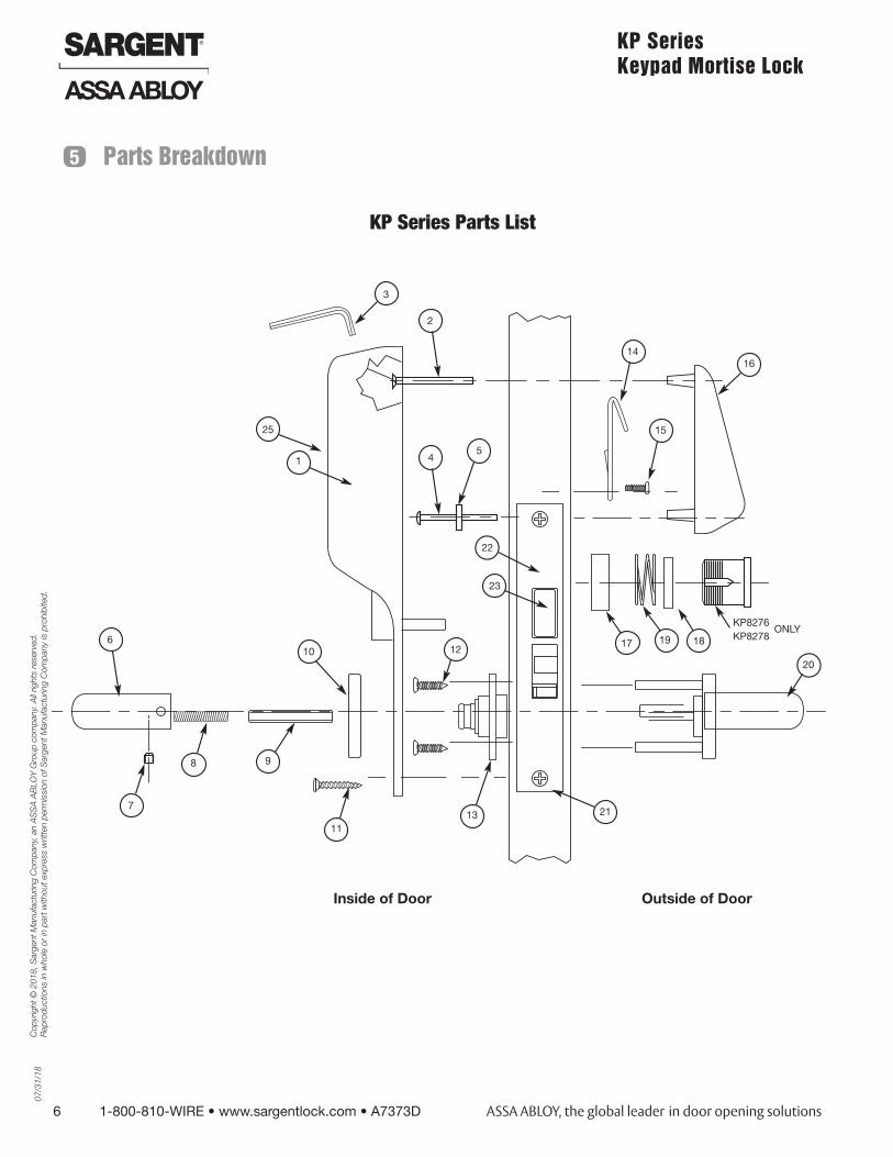
5 Parts Breakdown
6
1
2
3
45
7
8 9
10
11
12
22
23
13 21
17 1819
14
15
16
20
KP8276KP8278
ONLY
KP Series Parts List
Inside of Door Outside of Door
25
07/
31/1
8
1-800-810-WIRE • www.sargentlock.com • A7373D 7
Copy
right
© 2
018,
Sar
gent
Man
ufac
turin
g Co
mpa
ny, a
n AS
SA A
BLOY
Gro
up co
mpa
ny. A
ll rig
hts r
eser
ved.
Re
prod
uctio
ns in
who
le o
r in
part
with
out e
xpre
ss w
ritte
n pe
rmiss
ion
of S
arge
nt M
anuf
actu
ring
Com
pany
is p
rohi
bite
d.
KP Series Keypad Mortise Lock
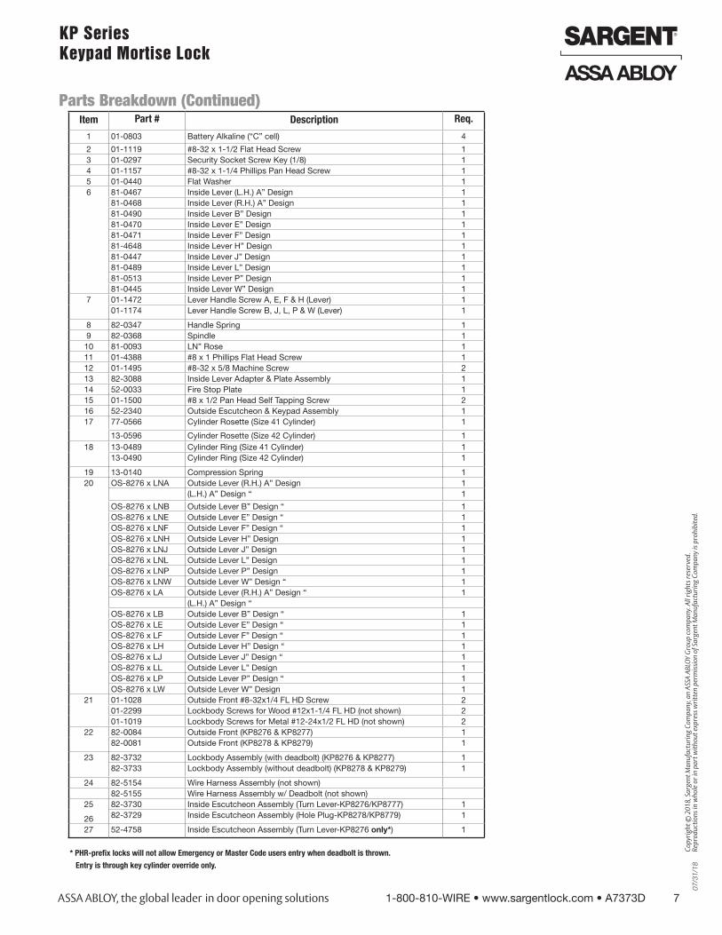
Parts Breakdown (Continued)Item Part # Description Req.
1 01-0803 Battery Alkaline (“C” cell) 4
2 01-1119 #8-32 x 1-1/2 Flat Head Screw 13 01-0297 Security Socket Screw Key (1/8) 14 01-1157 #8-32 x 1-1/4 Phillips Pan Head Screw 15 01-0440 Flat Washer 16 81-0467 Inside Lever (L.H.) A” Design 1
81-0468 Inside Lever (R.H.) A” Design 181-0490 Inside Lever B” Design 181-0470 Inside Lever E” Design 181-0471 Inside Lever F” Design 181-4648 Inside Lever H” Design 181-0447 Inside Lever J” Design 181-0489 Inside Lever L” Design 181-0513 Inside Lever P” Design 181-0445 Inside Lever W” Design 1
7 01-1472 Lever Handle Screw A, E, F & H (Lever) 101-1174 Lever Handle Screw B, J, L, P & W (Lever) 1
8 82-0347 Handle Spring 19 82-0368 Spindle 110 81-0093 LN” Rose 111 01-4388 #8 x 1 Phillips Flat Head Screw 112 01-1495 #8-32 x 5/8 Machine Screw 213 82-3088 Inside Lever Adapter & Plate Assembly 114 52-0033 Fire Stop Plate 115 01-1500 #8 x 1/2 Pan Head Self Tapping Screw 216 52-2340 Outside Escutcheon & Keypad Assembly 117 77-0566 Cylinder Rosette (Size 41 Cylinder) 1
13-0596 Cylinder Rosette (Size 42 Cylinder) 118 13-0489 Cylinder Ring (Size 41 Cylinder) 1
13-0490 Cylinder Ring (Size 42 Cylinder) 1
19 13-0140 Compression Spring 120 OS-8276 x LNA Outside Lever (R.H.) A” Design 1
(L.H.) A” Design “ 1
OS-8276 x LNB Outside Lever B” Design “ 1OS-8276 x LNE Outside Lever E” Design “ 1OS-8276 x LNF Outside Lever F” Design “ 1OS-8276 x LNH Outside Lever H” Design 1OS-8276 x LNJ Outside Lever J” Design 1OS-8276 x LNL Outside Lever L” Design 1OS-8276 x LNP Outside Lever P” Design 1OS-8276 x LNW Outside Lever W” Design “ 1OS-8276 x LA Outside Lever (R.H.) A” Design “ 1
(L.H.) A” Design “OS-8276 x LB Outside Lever B” Design “ 1OS-8276 x LE Outside Lever E” Design “ 1OS-8276 x LF Outside Lever F” Design “ 1OS-8276 x LH Outside Lever H” Design “ 1OS-8276 x LJ Outside Lever J” Design “ 1OS-8276 x LL Outside Lever L” Design 1OS-8276 x LP Outside Lever P” Design “ 1OS-8276 x LW Outside Lever W” Design 1
21 01-1028 Outside Front #8-32x1/4 FL HD Screw 201-2299 Lockbody Screws for Wood #12x1-1/4 FL HD (not shown) 201-1019 Lockbody Screws for Metal #12-24x1/2 FL HD (not shown) 2
22 82-0084 Outside Front (KP8276 & KP8277) 182-0081 Outside Front (KP8278 & KP8279) 1
23 82-3732 Lockbody Assembly (with deadbolt) (KP8276 & KP8277) 182-3733 Lockbody Assembly (without deadbolt) (KP8278 & KP8279) 1
24 82-5154 Wire Harness Assembly (not shown)82-5155 Wire Harness Assembly w/ Deadbolt (not shown)
25
26
82-3730 Inside Escutcheon Assembly (Turn Lever-KP8276/KP8777) 182-3729 Inside Escutcheon Assembly (Hole Plug-KP8278/KP8779) 1
27 52-4758 Inside Escutcheon Assembly (Turn Lever-KP8276 only*) 1
* PHR-prefix locks will not allow Emergency or Master Code users entry when deadbolt is thrown.
Entry is through key cylinder override only.
8 1-800-810-WIRE • www.sargentlock.com • A7373D
Cop
yrig
ht ©
201
8, S
arge
nt M
anuf
actu
ring
Com
pany
, an
AS
SA
AB
LOY
Gro
up c
ompa
ny. A
ll rig
hts
rese
rved
. R
epro
duct
ions
in w
hole
or
in p
art w
ithou
t exp
ress
writ
ten
perm
issi
on o
f Sar
gent
Man
ufac
turin
g C
ompa
ny is
pro
hibi
ted.
07/
31/1
8KP Series Keypad Mortise Lock
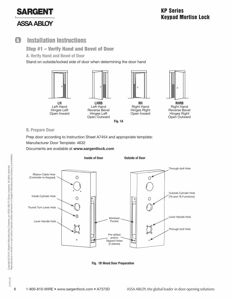
Installation Instructions6
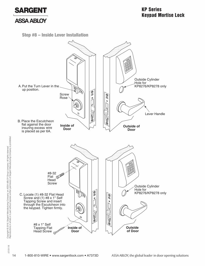
Step #1 – Verify Hand and Bevel of DoorA. Verify Hand and Bevel of DoorStand on outside/locked side of door when determining the door hand
B. Prepare Door
Prep door according to Instruction Sheet A7454 and appropriate template:
Manufacturer Door Template: 4632
Documents are available at www.sargentlock.com
LH Left Hand
Hinges Left Open Inward
LHRB Left Hand
Reverse Bevel Hinges Left
Open Outward
RH Right Hand
Hinges Right Open Inward
RHRB Right Hand
Reverse Bevel Hinges Right
Open Outward Fig. 1A
Through-bolt Hole
Outside Cylinder Hole(76 and 78 Functions)
Lever Handle Hole
Pre-drilled and/or
Tapped Holes (2 places)
Mortised Pocket
Ribbon Cable Hole (Controller to Keypad)
Inside Cylinder Hole
Thumb Turn Lever Hole
Lever Handle Hole
Outside of DoorInside of Door
Through-bolt Hole
Fig. 1B Wood Door Preparation
07/
31/1
8
1-800-810-WIRE • www.sargentlock.com • A7373D 9
Copy
right
© 2
018,
Sar
gent
Man
ufac
turin
g Co
mpa
ny, a
n AS
SA A
BLOY
Gro
up co
mpa
ny. A
ll rig
hts r
eser
ved.
Re
prod
uctio
ns in
who
le o
r in
part
with
out e
xpre
ss w
ritte
n pe
rmiss
ion
of S
arge
nt M
anuf
actu
ring
Com
pany
is p
rohi
bite
d.
KP Series Keypad Mortise Lock
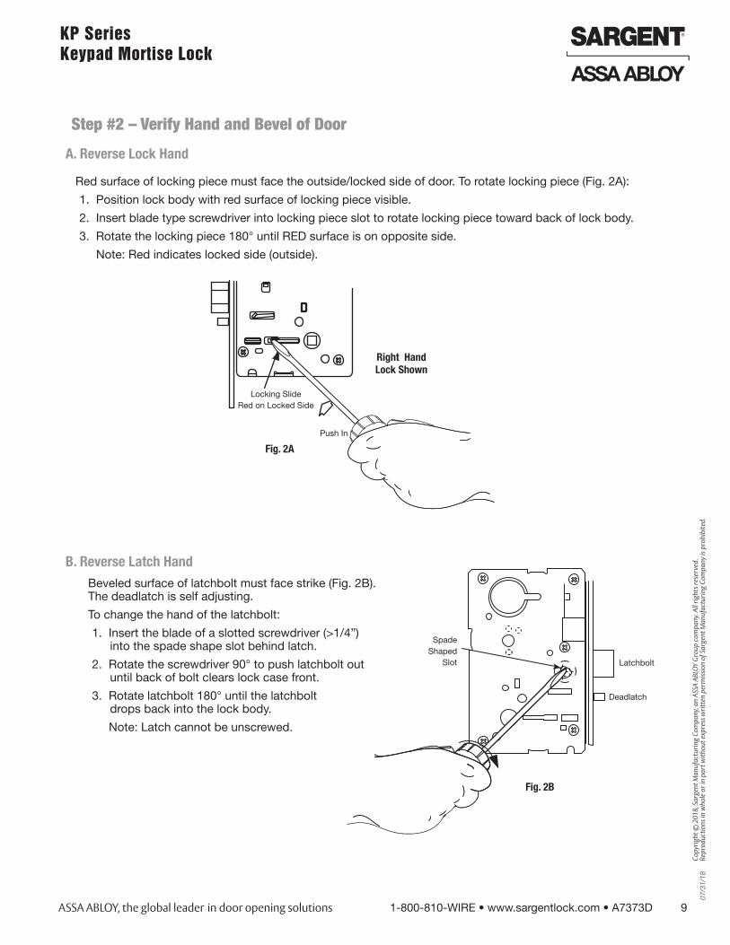
B. Reverse Latch HandBeveled surface of latchbolt must face strike (Fig. 2B). The deadlatch is self adjusting.
To change the hand of the latchbolt:
1. Insert the blade of a slotted screwdriver (>1/4”) into the spade shape slot behind latch.
2. Rotate the screwdriver 90° to push latchbolt out until back of bolt clears lock case front.
3. Rotate latchbolt 180° until the latchbolt drops back into the lock body.
Note: Latch cannot be unscrewed.
Latchbolt
Spade Shaped
Slot
Fig. 2B
Red surface of locking piece must face the outside/locked side of door. To rotate locking piece (Fig. 2A):
1. Position lock body with red surface of locking piece visible.
2. Insert blade type screwdriver into locking piece slot to rotate locking piece toward back of lock body.
3. Rotate the locking piece 180° until RED surface is on opposite side.
Note: Red indicates locked side (outside).
Locking SlideRed on Locked Side
Push In
Right HandLock Shown
Fig. 2A
Deadlatch
A. Reverse Lock Hand
Step #2 – Verify Hand and Bevel of Door
10 1-800-810-WIRE • www.sargentlock.com • A7373D
Cop
yrig
ht ©
201
8, S
arge
nt M
anuf
actu
ring
Com
pany
, an
AS
SA
AB
LOY
Gro
up c
ompa
ny. A
ll rig
hts
rese
rved
. R
epro
duct
ions
in w
hole
or
in p
art w
ithou
t exp
ress
writ
ten
perm
issi
on o
f Sar
gent
Man
ufac
turin
g C
ompa
ny is
pro
hibi
ted.
07/
31/1
8KP Series Keypad Mortise Lock
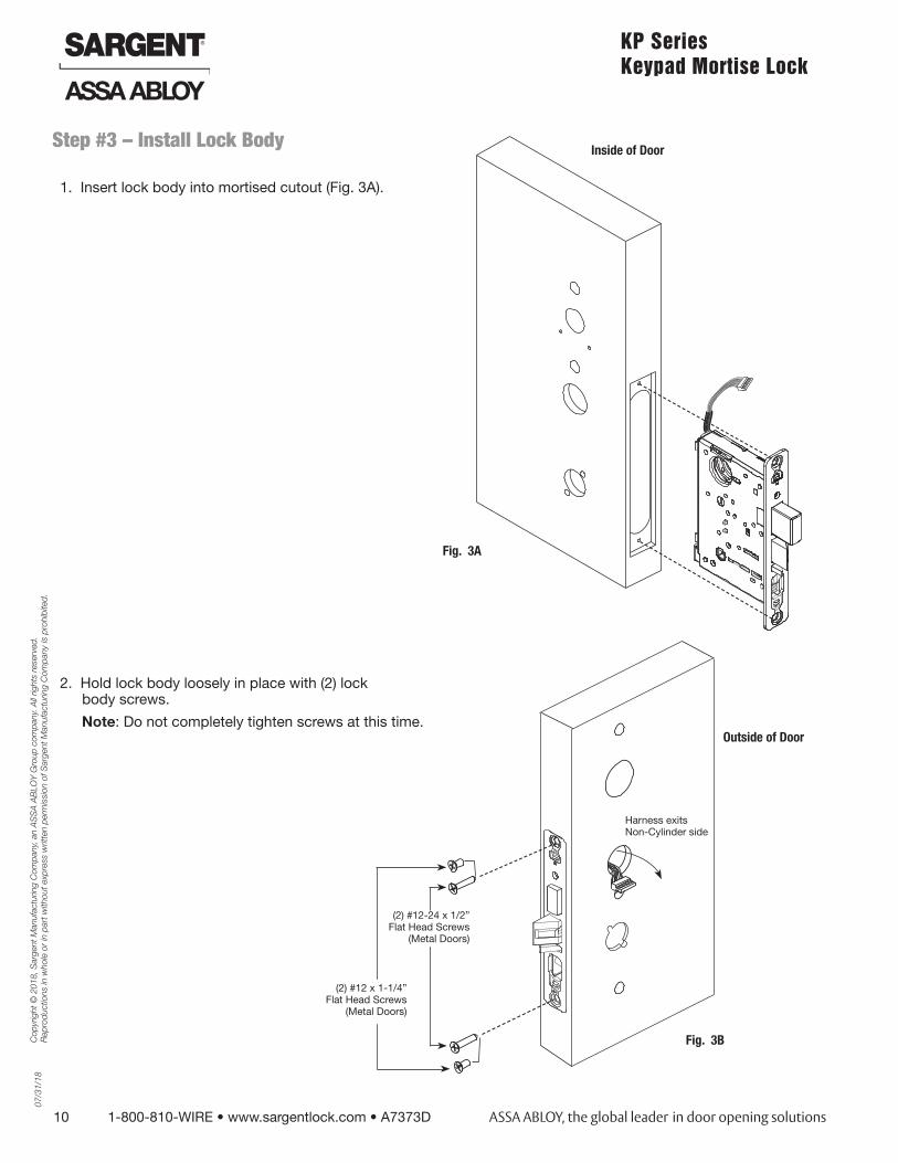
1. Insert lock body into mortised cutout (Fig. 3A).
Step #3 – Install Lock Body
(2) #12-24 x 1/2” Flat Head Screws
(Metal Doors)
(2) #12 x 1-1/4” Flat Head Screws
(Metal Doors)
Fig. 3A
Harness exits Non-Cylinder side
Fig. 3B
Outside of Door
Inside of Door
2. Hold lock body loosely in place with (2) lock body screws.
Note: Do not completely tighten screws at this time.
07/
31/1
8
1-800-810-WIRE • www.sargentlock.com • A7373D 11
Copy
right
© 2
018,
Sar
gent
Man
ufac
turin
g Co
mpa
ny, a
n AS
SA A
BLOY
Gro
up co
mpa
ny. A
ll rig
hts r
eser
ved.
Re
prod
uctio
ns in
who
le o
r in
part
with
out e
xpre
ss w
ritte
n pe
rmiss
ion
of S
arge
nt M
anuf
actu
ring
Com
pany
is p
rohi
bite
d.
KP Series Keypad Mortise Lock
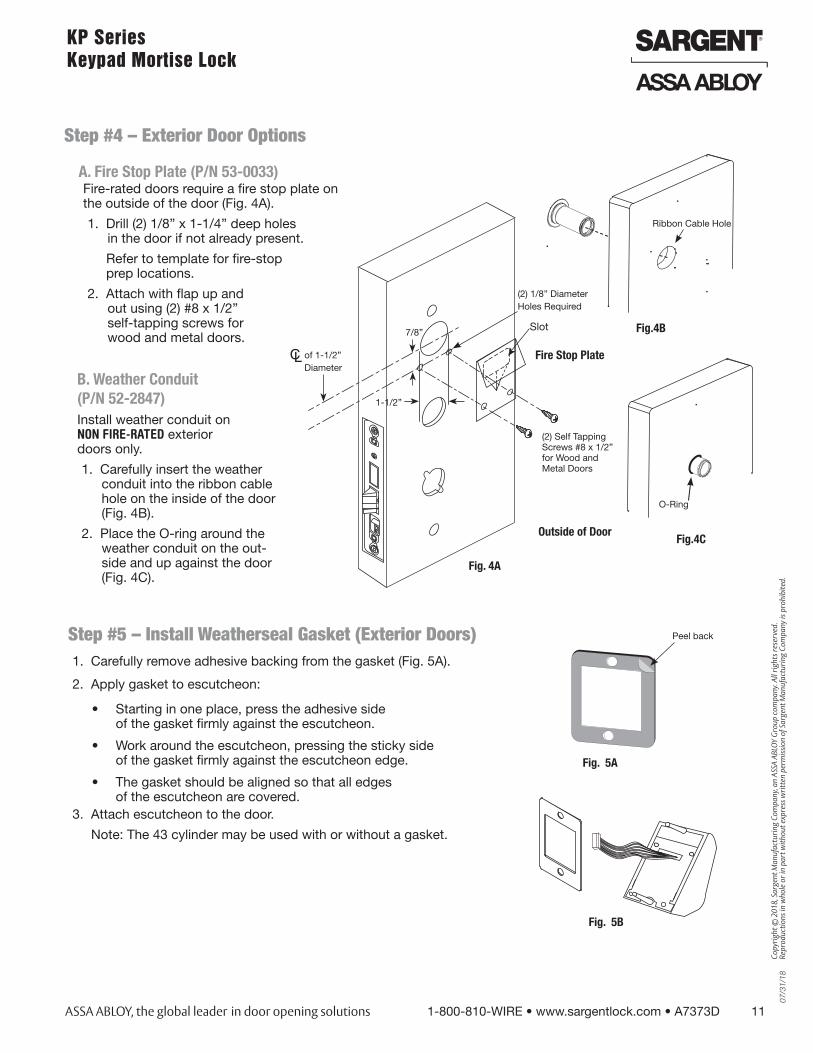
Fire-rated doors require a fire stop plate on the outside of the door (Fig. 4A).
1. Drill (2) 1/8” x 1-1/4” deep holes in the door if not already present.
Refer to template for fire-stop prep locations.
2. Attach with flap up and out using (2) #8 x 1/2” self-tapping screws for wood and metal doors.
B. Weather Conduit (P/N 52-2847)Install weather conduit on NON FIRE-RATED exterior doors only.
1. Carefully insert the weather conduit into the ribbon cable hole on the inside of the door (Fig. 4B).
2. Place the O-ring around the weather conduit on the out-side and up against the door (Fig. 4C).
of 1-1/2”Diameter
(2) 1/8” DiameterHoles Required
Fire Stop Plate
Slot
(2) Self Tapping Screws #8 x 1/2” for Wood and Metal Doors
Fig. 4A
A. Fire Stop Plate (P/N 53-0033)
7/8”
1-1/2”
Outside of Door
Fig.4B
Ribbon Cable Hole
Fig.4C
O-Ring
Step #4 – Exterior Door Options
Step #5 – Install Weatherseal Gasket (Exterior Doors)1. Carefully remove adhesive backing from the gasket (Fig. 5A).
2. Apply gasket to escutcheon:
• Starting in one place, press the adhesive side of the gasket firmly against the escutcheon.
• Work around the escutcheon, pressing the sticky side of the gasket firmly against the escutcheon edge.
• The gasket should be aligned so that all edges of the escutcheon are covered.
3. Attach escutcheon to the door.
Note: The 43 cylinder may be used with or without a gasket.
Fig. 5A
Fig. 5B
Peel back
12 1-800-810-WIRE • www.sargentlock.com • A7373D
Cop
yrig
ht ©
201
8, S
arge
nt M
anuf
actu
ring
Com
pany
, an
AS
SA
AB
LOY
Gro
up c
ompa
ny. A
ll rig
hts
rese
rved
. R
epro
duct
ions
in w
hole
or
in p
art w
ithou
t exp
ress
writ
ten
perm
issi
on o
f Sar
gent
Man
ufac
turin
g C
ompa
ny is
pro
hibi
ted.
07/
31/1
8KP Series Keypad Mortise Lock
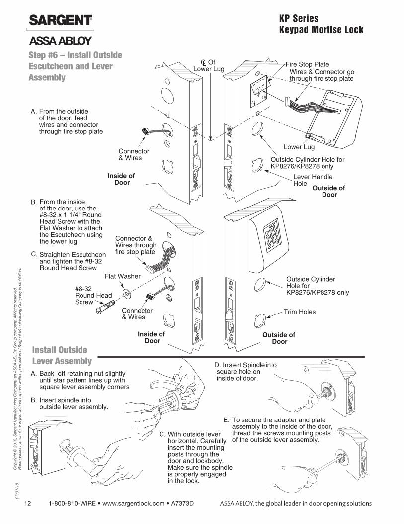
Step #6 – Install Outside Escutcheon and Lever Assembly
Install Outside Lever Assembly
07/
31/1
8
1-800-810-WIRE • www.sargentlock.com • A7373D 13
Copy
right
© 2
018,
Sar
gent
Man
ufac
turin
g Co
mpa
ny, a
n AS
SA A
BLOY
Gro
up co
mpa
ny. A
ll rig
hts r
eser
ved.
Re
prod
uctio
ns in
who
le o
r in
part
with
out e
xpre
ss w
ritte
n pe
rmiss
ion
of S
arge
nt M
anuf
actu
ring
Com
pany
is p
rohi
bite
d.
KP Series Keypad Mortise Lock
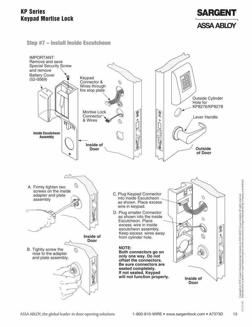
Step #7 – Install Inside Escutcheon
Inside Escutcheon Assembly
14 1-800-810-WIRE • www.sargentlock.com • A7373D
Cop
yrig
ht ©
201
8, S
arge
nt M
anuf
actu
ring
Com
pany
, an
AS
SA
AB
LOY
Gro
up c
ompa
ny. A
ll rig
hts
rese
rved
. R
epro
duct
ions
in w
hole
or
in p
art w
ithou
t exp
ress
writ
ten
perm
issi
on o
f Sar
gent
Man
ufac
turin
g C
ompa
ny is
pro
hibi
ted.
07/
31/1
8KP Series Keypad Mortise Lock
Step #8 – Inside Lever Installation
07/
31/1
8
1-800-810-WIRE • www.sargentlock.com • A7373D 15
Copy
right
© 2
018,
Sar
gent
Man
ufac
turin
g Co
mpa
ny, a
n AS
SA A
BLOY
Gro
up co
mpa
ny. A
ll rig
hts r
eser
ved.
Re
prod
uctio
ns in
who
le o
r in
part
with
out e
xpre
ss w
ritte
n pe
rmiss
ion
of S
arge
nt M
anuf
actu
ring
Com
pany
is p
rohi
bite
d.
KP Series Keypad Mortise Lock
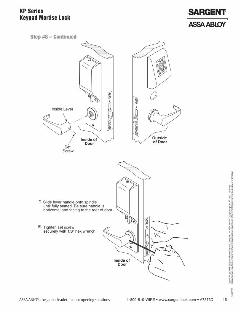
Step #8 – Continued
16 1-800-810-WIRE • www.sargentlock.com • A7373D
Cop
yrig
ht ©
201
8, S
arge
nt M
anuf
actu
ring
Com
pany
, an
AS
SA
AB
LOY
Gro
up c
ompa
ny. A
ll rig
hts
rese
rved
. R
epro
duct
ions
in w
hole
or
in p
art w
ithou
t exp
ress
writ
ten
perm
issi
on o
f Sar
gent
Man
ufac
turin
g C
ompa
ny is
pro
hibi
ted.
07/
31/1
8KP Series Keypad Mortise Lock
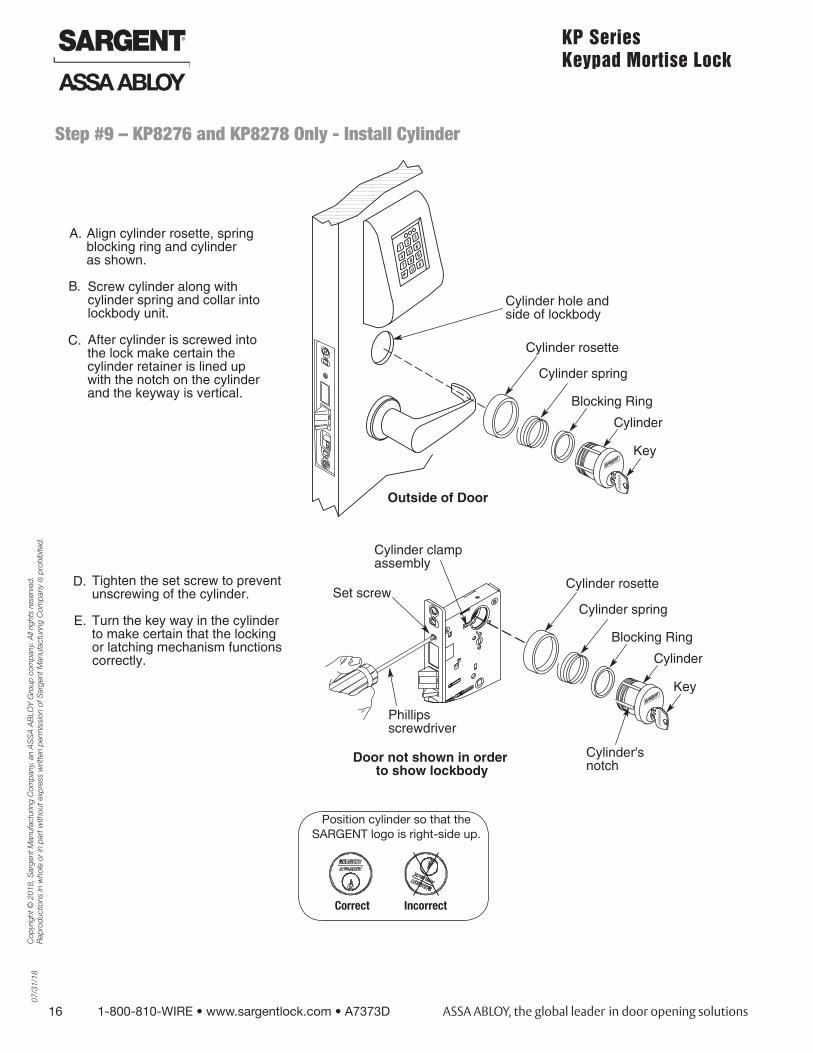
Step #9 – KP8276 and KP8278 Only - Install Cylinder
Position cylinder so that the SARGENT logo is right-side up.
Correct Incorrect

07/
31/1
8
1-800-810-WIRE • www.sargentlock.com • A7373D 17
Copy
right
© 2
018,
Sar
gent
Man
ufac
turin
g Co
mpa
ny, a
n AS
SA A
BLOY
Gro
up co
mpa
ny. A
ll rig
hts r
eser
ved.
Re
prod
uctio
ns in
who
le o
r in
part
with
out e
xpre
ss w
ritte
n pe
rmiss
ion
of S
arge
nt M
anuf
actu
ring
Com
pany
is p
rohi
bite
d.
KP Series Keypad Mortise Lock
Step #10 – Application of Front Plate
Step #11 – Battery Installation
18 1-800-810-WIRE • www.sargentlock.com • A7373D
Cop
yrig
ht ©
201
8, S
arge
nt M
anuf
actu
ring
Com
pany
, an
AS
SA
AB
LOY
Gro
up c
ompa
ny. A
ll rig
hts
rese
rved
. R
epro
duct
ions
in w
hole
or
in p
art w
ithou
t exp
ress
writ
ten
perm
issi
on o
f Sar
gent
Man
ufac
turin
g C
ompa
ny is
pro
hibi
ted.
07/
31/1
8KP Series Keypad Mortise Lock
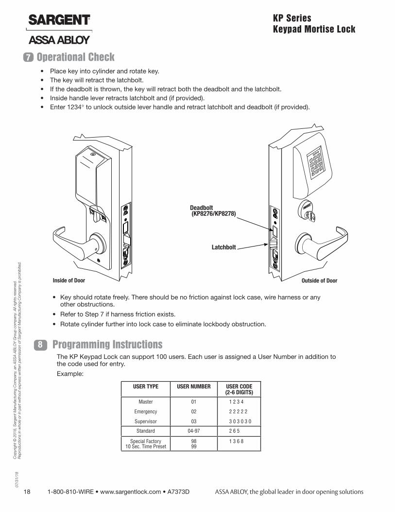
7 Operational Check• Place key into cylinder and rotate key.• The key will retract the latchbolt.• If the deadbolt is thrown, the key will retract both the deadbolt and the latchbolt.• Inside handle lever retracts latchbolt and (if provided).• Enter 1234* to unlock outside lever handle and retract latchbolt and deadbolt (if provided).
PQ
R
ST
U
VW
X
O
I
B
Latchbolt
Deadbolt (KP8276/KP8278)
Outside of DoorInside of Door
• Key should rotate freely. There should be no friction against lock case, wire harness or any other obstructions.
• Refer to Step 7 if harness friction exists.
• Rotate cylinder further into lock case to eliminate lockbody obstruction.
Programming InstructionsThe KP Keypad Lock can support 100 users. Each user is assigned a User Number in addition to the code used for entry.
Example:
USER TYPE USER NUMBER USER CODE (2-6 DIGITS)
Master
Emergency
Supervisor
01
02
03
1 2 3 4
2 2 2 2 2
3 0 3 0 3 0
Standard 04-97 2 6 5
Special Factory 10 Sec. Time Preset
98 99
1 3 6 8
8
07/
31/1
8
1-800-810-WIRE • www.sargentlock.com • A7373D 19
Copy
right
© 2
018,
Sar
gent
Man
ufac
turin
g Co
mpa
ny, a
n AS
SA A
BLOY
Gro
up co
mpa
ny. A
ll rig
hts r
eser
ved.
Re
prod
uctio
ns in
who
le o
r in
part
with
out e
xpre
ss w
ritte
n pe
rmiss
ion
of S
arge
nt M
anuf
actu
ring
Com
pany
is p
rohi
bite
d.
KP Series Keypad Mortise Lock
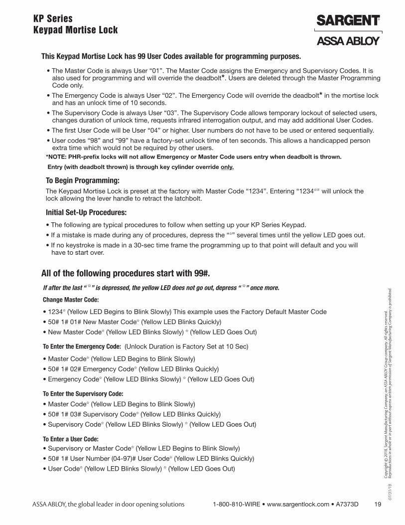
This Keypad Mortise Lock has 99 User Codes available for programming purposes.
• The Master Code is always User “01”. The Master Code assigns the Emergency and Supervisory Codes. It is also used for programming and will override the deadbolt*. Users are deleted through the Master Programming Code only.
• The Emergency Code is always User “02”. The Emergency Code will override the deadbolt* in the mortise lock and has an unlock time of 10 seconds.
• The Supervisory Code is always User “03”. The Supervisory Code allows temporary lockout of selected users, changes duration of unlock time, requests infrared interrogation output, and may add additional User Codes.
• The first User Code will be User “04” or higher. User numbers do not have to be used or entered sequentially.
• User codes “98” and “99” have a factory-set unlock time of ten seconds. This allows a handicapped person extra time which would not be required by other users.
To Begin Programming:The Keypad Mortise Lock is preset at the factory with Master Code “1234”. Entering “1234*” will unlock the lock allowing the lever handle to retract the latchbolt.
Initial Set-Up Procedures:
• The following are typical procedures to follow when setting up your KP Series Keypad.
• If a mistake is made during any of procedures, depress the “*” several times until the yellow LED goes out.
• If no keystroke is made in a 30-sec time frame the programming up to that point will default and you will have to start over.
If after the last “ *” is depressed, the yellow LED does not go out, depress “ *” once more.
Change Master Code:
• 1234* (Yellow LED Begins to Blink Slowly) This example uses the Factory Default Master Code
• 50# 1# 01# New Master Code* (Yellow LED Blinks Quickly)
• New Master Code* (Yellow LED Blinks Slowly) * (Yellow LED Goes Out)
To Enter the Emergency Code: (Unlock Duration is Factory Set at 10 Sec)
• Master Code* (Yellow LED Begins to Blink Slowly)
• 50# 1# 02# Emergency Code* (Yellow LED Blinks Quickly)
• Emergency Code* (Yellow LED Blinks Slowly) * (Yellow LED Goes Out)
To Enter the Supervisory Code:
• Master Code* (Yellow LED Begins to Blink Slowly)
• 50# 1# 03# Supervisory Code* (Yellow LED Blinks Quickly)
• Supervisory Code* (Yellow LED Blinks Slowly) * (Yellow LED Goes Out)
To Enter a User Code:• Supervisory or Master Code* (Yellow LED Begins to Blink Slowly)
• 50# 1# User Number (04-97)# User Code* (Yellow LED Blinks Quickly)
• User Code* (Yellow LED Blinks Slowly) * (Yellow LED Goes Out)
*NOTE: PHR-prefix locks will not allow Emergency or Master Code users entry when deadbolt is thrown.
Entry (with deadbolt thrown) is through key cylinder override only.
All of the following procedures start with 99#.
20 1-800-810-WIRE • www.sargentlock.com • A7373D
Cop
yrig
ht ©
201
8, S
arge
nt M
anuf
actu
ring
Com
pany
, an
AS
SA
AB
LOY
Gro
up c
ompa
ny. A
ll rig
hts
rese
rved
. R
epro
duct
ions
in w
hole
or
in p
art w
ithou
t exp
ress
writ
ten
perm
issi
on o
f Sar
gent
Man
ufac
turin
g C
ompa
ny is
pro
hibi
ted.
07/
31/1
8KP Series Keypad Mortise Lock
To Enter a Passage (Maintained Mode) Code:
All of the following procedures start with 99# (continued). If after the last “*” is depressed, the yellow LED does not go out, depress “*” once more.
When Passage Mode is used, the same User Code must be used to re-lock the lock.• Supervisory or Master Code* (Yellow LED Begins to Blink Slowly)
• 50# 2# User Number (04-97)# User Code* (Yellow LED Blinks Quickly)
• User Code* (Yellow LED Blinks Slowly) * (Yellow LED Goes Out)
To Enter a One Time User Code:
• Supervisory or Master Code* (Yellow LED Begins to Blink Slowly)
• 50# 3# User Number# User Code* (Yellow LED Blinks Quickly)
• User Code* (Yellow LED Blinks Slowly) * (Yellow LED Goes Out)
To Deactivate “Beep” With the Depression of Each Key:
• Supervisory or Master Code* (Yellow LED Begins to Blink Slowly)
• 30# 0# 0# (Yellow LED Continues to Blink Slowly)
• * (Yellow LED Blinks Quickly)
• * (No Beep on Depression and Yellow LED Blinks Slowly)
• * (No Beep on Depression and Yellow LED Goes Out)
To Reactivate “Beep” With the Depression of Each Key:
• Supervisory or Master Code* (Yellow LED Begins to Blink Slowly)
• 30# 0# 1# (Yellow LED Continues to Blink Slowly)
• * (Yellow LED Blinks Quickly)
• * (Beep on Depression and Yellow LED Blinks Slowly)
• * (Beep on Depression and Yellow LED Goes Out)
To Clear the Entire Memory:
• Master Code* (Yellow LED Begins to Blink Slowly)
• 46# 00000# 00000# (Yellow LED Continues to Blink Slowly)
• * (Yellow LED Blinks Quickly)
• * (No Beep on Depression and Yellow LED Goes Out)
• PAUSE, Yellow LED Begins to Blink Again
• * (Yellow LED Goes Out)
NOTE This Deletes ALL Codes, including Master, Emergency and Supervisory. The Master Code is set back to 1234, Door Number to 0001 and Unlock time to 5 Sec. If the Master Code is not known, Factory Assistance will be required to clear the memory. 1-800-810-WIRE.
To Program Door Numbers into Keypad:
• Master Code* (Yellow LED Begins to Blink Slowly)
• 43# 0# Door Number# (must be four digits) (Yellow LED Blinks Slowly)
• * (Yellow LED Begins to Blink Quickly)
• * (Yellow LED Blink Slowly)
• * (Yellow LED Goes Out)
07/
31/1
8
1-800-810-WIRE • www.sargentlock.com • A7373D 21
Copy
right
© 2
018,
Sar
gent
Man
ufac
turin
g Co
mpa
ny, a
n AS
SA A
BLOY
Gro
up co
mpa
ny. A
ll rig
hts r
eser
ved.
Re
prod
uctio
ns in
who
le o
r in
part
with
out e
xpre
ss w
ritte
n pe
rmiss
ion
of S
arge
nt M
anuf
actu
ring
Com
pany
is p
rohi
bite
d.
KP Series Keypad Mortise Lock
All of the following procedures start with 99# (continued). If after the last “*” is depressed, the yellow LED does not go out, depress “*” once more.
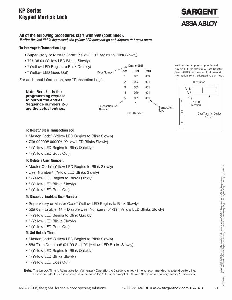
To Interrogate Transaction Log:
• Supervisory or Master Code* (Yellow LED Begins to Blink Slowly)
• 70# 0# 0# (Yellow LED Blinks Slowly)
• * (Yellow LED Begins to Blink Quickly)
• * (Yellow LED Goes Out)
For additional information, see “Transaction Log”.
Hold an infrared printer up to the redinfrared LED (as shown). A Data Transfer Device (DTD) can be used to downloadinformation from the keypad to a printout.
Illustration
To LED location
DataTransfer Device (DTD)
Note: Seq. # 1 is the programming request to output the entries. Sequence numbers 2-6 are the actual entries.
Door # 5666
Seq User Trans
1 001 003
2 003 001
3 003 001
4 020 001
5 003 001
Door Number
Transaction Number
User Number
Transaction Type
To Reset / Clear Transaction Log
• Master Code* (Yellow LED Begins to Blink Slowly)
• 76# 00000# 00000# (Yellow LED Blinks Slowly)
• * (Yellow LED Begins to Blink Quickly)
• * (Yellow LED Goes Out)
To Delete a User Number:
• Master Code* (Yellow LED Begins to Blink Slowly)
• User Number# (Yellow LED Blinks Slowly)
• * (Yellow LED Begins to Blink Quickly)
• * (Yellow LED Blinks Slowly)
• * (Yellow LED Goes Out)
To Disable / Enable a User Number:
• Supervisory or Master Code* (Yellow LED Begins to Blink Slowly)
• 56# 0# = Enable, 1# = Disable User Number# (04-99) (Yellow LED Blinks Slowly)
• * (Yellow LED Begins to Blink Quickly)
• * (Yellow LED Blinks Slowly)
• * (Yellow LED Goes Out)
To Set Unlock Time:
• Master Code* (Yellow LED Begins to Blink Slowly)
• 85# Time Duration# (01-99 Sec) 0# (Yellow LED Blinks Slowly)
• * (Yellow LED Begins to Blink Quickly)
• * (Yellow LED Blinks Slowly)
• * (Yellow LED Goes Out)
Note: The Unlock Time is Adjustable for Momentary Operation. A 5 second unlock time is recommended to extend battery life.Once the unlock time is entered, it is the same for ALL users except 02, 98 and 99 which are factory set for 10 seconds.
22 1-800-810-WIRE • www.sargentlock.com • A7373D
Cop
yrig
ht ©
201
8, S
arge
nt M
anuf
actu
ring
Com
pany
, an
AS
SA
AB
LOY
Gro
up c
ompa
ny. A
ll rig
hts
rese
rved
. R
epro
duct
ions
in w
hole
or
in p
art w
ithou
t exp
ress
writ
ten
perm
issi
on o
f Sar
gent
Man
ufac
turin
g C
ompa
ny is
pro
hibi
ted.
07/
31/1
8KP Series Keypad Mortise Lock
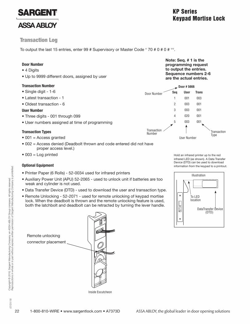
Transaction Log
To output the last 15 entries, enter 99 # Supervisory or Master Code * 70 # 0 # 0 # **.
Door Number• 4 Digits
• Up to 9999 different doors, assigned by user
Transaction Number• Single digit - 1-6
• Latest transaction - 1
• Oldest transaction - 6
User Number• Three digits - 001 through 099
• User numbers assigned at time of programming
Transaction Types• 001 = Access granted
• 002 = Access denied (Deadbolt thrown and code entered did not have proper access level.)
• 003 = Log printed
Optional Equipment
• Printer Paper (6 Rolls) - 52-0034 used for infrared printers
• Auxiliary Power Unit (APU) 52-2065 - used to unlock unit if batteries are too weak and cylinder is not used.
• Data Transfer Device (DTD) - used to download the user and transaction type.
• Remote Unlocking - 52-2071 - used for remote unlocking of keypad mortise lock. When the deadbolt is thrown and the remote unlocking feature is used, both the latchbolt and deadbolt can be retracted by turning the lever handle.
Hold an infrared printer up to the redinfrared LED (as shown). A Data Transfer Device (DTD) can be used to downloadinformation from the keypad to a printout.
Illustration
To LED location
DataTransfer Device (DTD)
Note: Seq. # 1 is the programming request to output the entries. Sequence numbers 2-6 are the actual entries.
Door # 5666
Seq User Trans
1 001 003
2 003 001
3 003 001
4 020 001
5 003 001
Door Number
Transaction Number
User Number
Transaction Type
Remote unlocking
connector placement
Inside Escutcheon

SARGENT Manufacturing Company100 Sargent DriveNew Haven, CT 06511 USA800-810-WIRE (9473) • www.sargentlock.com
Founded in the early 1800s, SARGENT® is a market leader in locksets, cylinders, door closers, exit devices,electro-mechanical products and access control systems for new construction, renovation, and replacement applications.The company’s customer base includes commercial construction, institutional, and industrial markets.
Copyright © 2018, Sargent Manufacturing Company, an ASSA ABLOY Group company. All rights reserved.Reproduction in whole or in part without the express written permission of Sargent Manufacturing Company is prohibited.
ASSA ABLOY is the global leader in door opening solutions, dedicated tosatisfying end-user needs for security, safety and convenience. A7373D- 07/18