kr c1 / kr c2 / kr c3 - kreysler's kukarobot.zaab.org/wp-content/uploads/2014/04/krl... · 1...
TRANSCRIPT

RefGuideR4.1 09.01.00 en
1 of 135
SOFTWARE
KR C1 / KR C2 / KR C3
Reference Guide
Release 4.1

2 of 135
RefGuideR4.1 09.01.00 en
e Copyright KUKA Roboter GmbHThis documentation or excerpts therefrommay not be reproduced or disclosed to third parties without the express permission of the publishers.Other functions not described in this documentation may be operable in the controller. The user has no claim to these functions, however, inthe case of a replacement or service work.We have checked the content of this documentation for conformity with the hardware and software described. Nevertheless, discrepanciescannot be precluded, for which reason we are not able to guarantee total conformity. The information in this documentation is checked on aregular basis, however, and necessary corrections will be incorporated in subsequent editions.Subject to technical alterations without an effect on the function.
PD Interleaf

3 of 135
RefGuideR4.1 09.01.00 en
Contents
1 General 9. . . . . . . . . . . . . . . . . . . . . . . . . . . . . . . . . . . . . . . . . . . . . . . . . . . . . . . . .
1.1 Typographical conventions 9. . . . . . . . . . . . . . . . . . . . . . . . . . . . . . . . . . . . . . . . . . . . . . . . . . . . . .
1.2 Graphic conventions 10. . . . . . . . . . . . . . . . . . . . . . . . . . . . . . . . . . . . . . . . . . . . . . . . . . . . . . . . . . .
2 Reference section 11. . . . . . . . . . . . . . . . . . . . . . . . . . . . . . . . . . . . . . . . . . . . . . . .
2.1 Fundamentals 11. . . . . . . . . . . . . . . . . . . . . . . . . . . . . . . . . . . . . . . . . . . . . . . . . . . . . . . . . . . . . . . . .2.1.1 Programs, data lists and modules 11. . . . . . . . . . . . . . . . . . . . . . . . . . . . . . . . . . . . . . . . . . . . . . . .2.1.2 Names and literals 11. . . . . . . . . . . . . . . . . . . . . . . . . . . . . . . . . . . . . . . . . . . . . . . . . . . . . . . . . . . . .2.1.3 Data types 11. . . . . . . . . . . . . . . . . . . . . . . . . . . . . . . . . . . . . . . . . . . . . . . . . . . . . . . . . . . . . . . . . . . .2.1.3.1 Simple data types 11. . . . . . . . . . . . . . . . . . . . . . . . . . . . . . . . . . . . . . . . . . . . . . . . . . . . . . . . . . . . . .2.1.3.2 Implicit type conversion 12. . . . . . . . . . . . . . . . . . . . . . . . . . . . . . . . . . . . . . . . . . . . . . . . . . . . . . . . .2.1.3.3 Predefined data types 12. . . . . . . . . . . . . . . . . . . . . . . . . . . . . . . . . . . . . . . . . . . . . . . . . . . . . . . . . .2.1.3.4 Implicit data type assignment 12. . . . . . . . . . . . . . . . . . . . . . . . . . . . . . . . . . . . . . . . . . . . . . . . . . . .2.1.4 Constants 12. . . . . . . . . . . . . . . . . . . . . . . . . . . . . . . . . . . . . . . . . . . . . . . . . . . . . . . . . . . . . . . . . . . . .2.1.5 Variables 13. . . . . . . . . . . . . . . . . . . . . . . . . . . . . . . . . . . . . . . . . . . . . . . . . . . . . . . . . . . . . . . . . . . . .2.1.5.1 System variables 13. . . . . . . . . . . . . . . . . . . . . . . . . . . . . . . . . . . . . . . . . . . . . . . . . . . . . . . . . . . . . .2.1.6 Operators 13. . . . . . . . . . . . . . . . . . . . . . . . . . . . . . . . . . . . . . . . . . . . . . . . . . . . . . . . . . . . . . . . . . . . .2.1.6.1 Arithmetic operators 13. . . . . . . . . . . . . . . . . . . . . . . . . . . . . . . . . . . . . . . . . . . . . . . . . . . . . . . . . . . .2.1.6.2 Logic operators 13. . . . . . . . . . . . . . . . . . . . . . . . . . . . . . . . . . . . . . . . . . . . . . . . . . . . . . . . . . . . . . . .2.1.6.3 Relational operators 13. . . . . . . . . . . . . . . . . . . . . . . . . . . . . . . . . . . . . . . . . . . . . . . . . . . . . . . . . . . .2.1.6.4 Bit operators 13. . . . . . . . . . . . . . . . . . . . . . . . . . . . . . . . . . . . . . . . . . . . . . . . . . . . . . . . . . . . . . . . . .2.1.6.5 Geometric operator 13. . . . . . . . . . . . . . . . . . . . . . . . . . . . . . . . . . . . . . . . . . . . . . . . . . . . . . . . . . . .2.1.6.6 Priority of operators 14. . . . . . . . . . . . . . . . . . . . . . . . . . . . . . . . . . . . . . . . . . . . . . . . . . . . . . . . . . . .2.1.7 Declaration 14. . . . . . . . . . . . . . . . . . . . . . . . . . . . . . . . . . . . . . . . . . . . . . . . . . . . . . . . . . . . . . . . . . . .2.1.8 Initialization 14. . . . . . . . . . . . . . . . . . . . . . . . . . . . . . . . . . . . . . . . . . . . . . . . . . . . . . . . . . . . . . . . . . .2.1.9 Expression 14. . . . . . . . . . . . . . . . . . . . . . . . . . . . . . . . . . . . . . . . . . . . . . . . . . . . . . . . . . . . . . . . . . . .2.1.10 Statement 14. . . . . . . . . . . . . . . . . . . . . . . . . . . . . . . . . . . . . . . . . . . . . . . . . . . . . . . . . . . . . . . . . . . .2.1.11 Comment 14. . . . . . . . . . . . . . . . . . . . . . . . . . . . . . . . . . . . . . . . . . . . . . . . . . . . . . . . . . . . . . . . . . . . .2.1.12 Motion programming 15. . . . . . . . . . . . . . . . . . . . . . . . . . . . . . . . . . . . . . . . . . . . . . . . . . . . . . . . . . .2.1.12.1 PTP motions (PTP = Point--To--Point) 15. . . . . . . . . . . . . . . . . . . . . . . . . . . . . . . . . . . . . . . . . . . . .2.1.12.2 CP motions (CP = Continuous Path) 15. . . . . . . . . . . . . . . . . . . . . . . . . . . . . . . . . . . . . . . . . . . . . .2.1.13 Control structures 15. . . . . . . . . . . . . . . . . . . . . . . . . . . . . . . . . . . . . . . . . . . . . . . . . . . . . . . . . . . . . .2.1.14 Subprograms 15. . . . . . . . . . . . . . . . . . . . . . . . . . . . . . . . . . . . . . . . . . . . . . . . . . . . . . . . . . . . . . . . . .2.1.15 Functions 15. . . . . . . . . . . . . . . . . . . . . . . . . . . . . . . . . . . . . . . . . . . . . . . . . . . . . . . . . . . . . . . . . . . . .2.1.16 Block structure 15. . . . . . . . . . . . . . . . . . . . . . . . . . . . . . . . . . . . . . . . . . . . . . . . . . . . . . . . . . . . . . . .2.1.17 Areas of validity 16. . . . . . . . . . . . . . . . . . . . . . . . . . . . . . . . . . . . . . . . . . . . . . . . . . . . . . . . . . . . . . . .2.1.18 Keywords 16. . . . . . . . . . . . . . . . . . . . . . . . . . . . . . . . . . . . . . . . . . . . . . . . . . . . . . . . . . . . . . . . . . . . .
2.2 Command index 20. . . . . . . . . . . . . . . . . . . . . . . . . . . . . . . . . . . . . . . . . . . . . . . . . . . . . . . . . . . . . . .2.2.1 ANIN 20. . . . . . . . . . . . . . . . . . . . . . . . . . . . . . . . . . . . . . . . . . . . . . . . . . . . . . . . . . . . . . . . . . . . . . . . .2.2.1.1 Brief information 20. . . . . . . . . . . . . . . . . . . . . . . . . . . . . . . . . . . . . . . . . . . . . . . . . . . . . . . . . . . . . . .2.2.1.2 Syntax 20. . . . . . . . . . . . . . . . . . . . . . . . . . . . . . . . . . . . . . . . . . . . . . . . . . . . . . . . . . . . . . . . . . . . . . .2.2.1.3 Description 20. . . . . . . . . . . . . . . . . . . . . . . . . . . . . . . . . . . . . . . . . . . . . . . . . . . . . . . . . . . . . . . . . . . .2.2.1.4 Example 21. . . . . . . . . . . . . . . . . . . . . . . . . . . . . . . . . . . . . . . . . . . . . . . . . . . . . . . . . . . . . . . . . . . . . .2.2.2 ANOUT 22. . . . . . . . . . . . . . . . . . . . . . . . . . . . . . . . . . . . . . . . . . . . . . . . . . . . . . . . . . . . . . . . . . . . . . .2.2.2.1 Brief information 22. . . . . . . . . . . . . . . . . . . . . . . . . . . . . . . . . . . . . . . . . . . . . . . . . . . . . . . . . . . . . . .2.2.2.2 Syntax 22. . . . . . . . . . . . . . . . . . . . . . . . . . . . . . . . . . . . . . . . . . . . . . . . . . . . . . . . . . . . . . . . . . . . . . .2.2.2.3 Description 22. . . . . . . . . . . . . . . . . . . . . . . . . . . . . . . . . . . . . . . . . . . . . . . . . . . . . . . . . . . . . . . . . . . .2.2.2.4 Example 23. . . . . . . . . . . . . . . . . . . . . . . . . . . . . . . . . . . . . . . . . . . . . . . . . . . . . . . . . . . . . . . . . . . . . .

Reference Guide
4 of 135
RefGuideR4.1 09.01.00 en
2.2.3 BRAKE 24. . . . . . . . . . . . . . . . . . . . . . . . . . . . . . . . . . . . . . . . . . . . . . . . . . . . . . . . . . . . . . . . . . . . . . .2.2.3.1 Brief information 24. . . . . . . . . . . . . . . . . . . . . . . . . . . . . . . . . . . . . . . . . . . . . . . . . . . . . . . . . . . . . . .2.2.3.2 Syntax 24. . . . . . . . . . . . . . . . . . . . . . . . . . . . . . . . . . . . . . . . . . . . . . . . . . . . . . . . . . . . . . . . . . . . . . .2.2.3.3 Description 24. . . . . . . . . . . . . . . . . . . . . . . . . . . . . . . . . . . . . . . . . . . . . . . . . . . . . . . . . . . . . . . . . . . .2.2.3.4 Example 24. . . . . . . . . . . . . . . . . . . . . . . . . . . . . . . . . . . . . . . . . . . . . . . . . . . . . . . . . . . . . . . . . . . . . .2.2.4 CCLOSE 25. . . . . . . . . . . . . . . . . . . . . . . . . . . . . . . . . . . . . . . . . . . . . . . . . . . . . . . . . . . . . . . . . . . . .2.2.4.1 Brief information 25. . . . . . . . . . . . . . . . . . . . . . . . . . . . . . . . . . . . . . . . . . . . . . . . . . . . . . . . . . . . . . .2.2.4.2 Syntax 25. . . . . . . . . . . . . . . . . . . . . . . . . . . . . . . . . . . . . . . . . . . . . . . . . . . . . . . . . . . . . . . . . . . . . . .2.2.4.3 Description 25. . . . . . . . . . . . . . . . . . . . . . . . . . . . . . . . . . . . . . . . . . . . . . . . . . . . . . . . . . . . . . . . . . . .2.2.4.4 Example 25. . . . . . . . . . . . . . . . . . . . . . . . . . . . . . . . . . . . . . . . . . . . . . . . . . . . . . . . . . . . . . . . . . . . . .2.2.5 CHANNEL 27. . . . . . . . . . . . . . . . . . . . . . . . . . . . . . . . . . . . . . . . . . . . . . . . . . . . . . . . . . . . . . . . . . . .2.2.5.1 Brief information 27. . . . . . . . . . . . . . . . . . . . . . . . . . . . . . . . . . . . . . . . . . . . . . . . . . . . . . . . . . . . . . .2.2.5.2 Syntax 27. . . . . . . . . . . . . . . . . . . . . . . . . . . . . . . . . . . . . . . . . . . . . . . . . . . . . . . . . . . . . . . . . . . . . . .2.2.5.3 Description 27. . . . . . . . . . . . . . . . . . . . . . . . . . . . . . . . . . . . . . . . . . . . . . . . . . . . . . . . . . . . . . . . . . . .2.2.5.4 Example 28. . . . . . . . . . . . . . . . . . . . . . . . . . . . . . . . . . . . . . . . . . . . . . . . . . . . . . . . . . . . . . . . . . . . . .2.2.6 CIRC 29. . . . . . . . . . . . . . . . . . . . . . . . . . . . . . . . . . . . . . . . . . . . . . . . . . . . . . . . . . . . . . . . . . . . . . . . .2.2.6.1 Brief information 29. . . . . . . . . . . . . . . . . . . . . . . . . . . . . . . . . . . . . . . . . . . . . . . . . . . . . . . . . . . . . . .2.2.6.2 Syntax 29. . . . . . . . . . . . . . . . . . . . . . . . . . . . . . . . . . . . . . . . . . . . . . . . . . . . . . . . . . . . . . . . . . . . . . .2.2.6.3 Description 31. . . . . . . . . . . . . . . . . . . . . . . . . . . . . . . . . . . . . . . . . . . . . . . . . . . . . . . . . . . . . . . . . . . .2.2.6.4 Example 33. . . . . . . . . . . . . . . . . . . . . . . . . . . . . . . . . . . . . . . . . . . . . . . . . . . . . . . . . . . . . . . . . . . . . .2.2.7 CIRC_REL 34. . . . . . . . . . . . . . . . . . . . . . . . . . . . . . . . . . . . . . . . . . . . . . . . . . . . . . . . . . . . . . . . . . . .2.2.7.1 Brief information 34. . . . . . . . . . . . . . . . . . . . . . . . . . . . . . . . . . . . . . . . . . . . . . . . . . . . . . . . . . . . . . .2.2.7.2 Syntax 34. . . . . . . . . . . . . . . . . . . . . . . . . . . . . . . . . . . . . . . . . . . . . . . . . . . . . . . . . . . . . . . . . . . . . . .2.2.7.3 Description 36. . . . . . . . . . . . . . . . . . . . . . . . . . . . . . . . . . . . . . . . . . . . . . . . . . . . . . . . . . . . . . . . . . . .2.2.7.4 Example 37. . . . . . . . . . . . . . . . . . . . . . . . . . . . . . . . . . . . . . . . . . . . . . . . . . . . . . . . . . . . . . . . . . . . . .2.2.8 CONFIRM 38. . . . . . . . . . . . . . . . . . . . . . . . . . . . . . . . . . . . . . . . . . . . . . . . . . . . . . . . . . . . . . . . . . . .2.2.8.1 Brief information 38. . . . . . . . . . . . . . . . . . . . . . . . . . . . . . . . . . . . . . . . . . . . . . . . . . . . . . . . . . . . . . .2.2.8.2 Syntax 38. . . . . . . . . . . . . . . . . . . . . . . . . . . . . . . . . . . . . . . . . . . . . . . . . . . . . . . . . . . . . . . . . . . . . . .2.2.8.3 Description 38. . . . . . . . . . . . . . . . . . . . . . . . . . . . . . . . . . . . . . . . . . . . . . . . . . . . . . . . . . . . . . . . . . . .2.2.8.4 Example 39. . . . . . . . . . . . . . . . . . . . . . . . . . . . . . . . . . . . . . . . . . . . . . . . . . . . . . . . . . . . . . . . . . . . . .2.2.9 CONTINUE 40. . . . . . . . . . . . . . . . . . . . . . . . . . . . . . . . . . . . . . . . . . . . . . . . . . . . . . . . . . . . . . . . . . .2.2.9.1 Brief information 40. . . . . . . . . . . . . . . . . . . . . . . . . . . . . . . . . . . . . . . . . . . . . . . . . . . . . . . . . . . . . . .2.2.9.2 Syntax 40. . . . . . . . . . . . . . . . . . . . . . . . . . . . . . . . . . . . . . . . . . . . . . . . . . . . . . . . . . . . . . . . . . . . . . .2.2.9.3 Description 40. . . . . . . . . . . . . . . . . . . . . . . . . . . . . . . . . . . . . . . . . . . . . . . . . . . . . . . . . . . . . . . . . . . .2.2.9.4 Example 40. . . . . . . . . . . . . . . . . . . . . . . . . . . . . . . . . . . . . . . . . . . . . . . . . . . . . . . . . . . . . . . . . . . . . .2.2.10 COPEN 41. . . . . . . . . . . . . . . . . . . . . . . . . . . . . . . . . . . . . . . . . . . . . . . . . . . . . . . . . . . . . . . . . . . . . .2.2.10.1 Brief information 41. . . . . . . . . . . . . . . . . . . . . . . . . . . . . . . . . . . . . . . . . . . . . . . . . . . . . . . . . . . . . . .2.2.10.2 Syntax 41. . . . . . . . . . . . . . . . . . . . . . . . . . . . . . . . . . . . . . . . . . . . . . . . . . . . . . . . . . . . . . . . . . . . . . .2.2.10.3 Description 41. . . . . . . . . . . . . . . . . . . . . . . . . . . . . . . . . . . . . . . . . . . . . . . . . . . . . . . . . . . . . . . . . . . .2.2.10.4 Example 41. . . . . . . . . . . . . . . . . . . . . . . . . . . . . . . . . . . . . . . . . . . . . . . . . . . . . . . . . . . . . . . . . . . . . .2.2.11 CREAD 42. . . . . . . . . . . . . . . . . . . . . . . . . . . . . . . . . . . . . . . . . . . . . . . . . . . . . . . . . . . . . . . . . . . . . . .2.2.11.1 Brief information 42. . . . . . . . . . . . . . . . . . . . . . . . . . . . . . . . . . . . . . . . . . . . . . . . . . . . . . . . . . . . . . .2.2.11.2 Syntax 42. . . . . . . . . . . . . . . . . . . . . . . . . . . . . . . . . . . . . . . . . . . . . . . . . . . . . . . . . . . . . . . . . . . . . . .2.2.11.3 Description 44. . . . . . . . . . . . . . . . . . . . . . . . . . . . . . . . . . . . . . . . . . . . . . . . . . . . . . . . . . . . . . . . . . . .2.2.12 CWRITE 48. . . . . . . . . . . . . . . . . . . . . . . . . . . . . . . . . . . . . . . . . . . . . . . . . . . . . . . . . . . . . . . . . . . . . .2.2.12.1 Brief information 48. . . . . . . . . . . . . . . . . . . . . . . . . . . . . . . . . . . . . . . . . . . . . . . . . . . . . . . . . . . . . . .2.2.12.2 Syntax 48. . . . . . . . . . . . . . . . . . . . . . . . . . . . . . . . . . . . . . . . . . . . . . . . . . . . . . . . . . . . . . . . . . . . . . .2.2.12.3 Description 49. . . . . . . . . . . . . . . . . . . . . . . . . . . . . . . . . . . . . . . . . . . . . . . . . . . . . . . . . . . . . . . . . . . .2.2.12.4 Example 51. . . . . . . . . . . . . . . . . . . . . . . . . . . . . . . . . . . . . . . . . . . . . . . . . . . . . . . . . . . . . . . . . . . . . .2.2.13 DECL 53. . . . . . . . . . . . . . . . . . . . . . . . . . . . . . . . . . . . . . . . . . . . . . . . . . . . . . . . . . . . . . . . . . . . . . . .2.2.13.1 Brief information 53. . . . . . . . . . . . . . . . . . . . . . . . . . . . . . . . . . . . . . . . . . . . . . . . . . . . . . . . . . . . . . .2.2.13.2 Syntax 53. . . . . . . . . . . . . . . . . . . . . . . . . . . . . . . . . . . . . . . . . . . . . . . . . . . . . . . . . . . . . . . . . . . . . . .2.2.13.3 Description 54. . . . . . . . . . . . . . . . . . . . . . . . . . . . . . . . . . . . . . . . . . . . . . . . . . . . . . . . . . . . . . . . . . . .2.2.13.4 Example: 56. . . . . . . . . . . . . . . . . . . . . . . . . . . . . . . . . . . . . . . . . . . . . . . . . . . . . . . . . . . . . . . . . . . . .
5 of 135
RefGuideR4.1 09.01.00 en
2.2.14 DEF ... END 57. . . . . . . . . . . . . . . . . . . . . . . . . . . . . . . . . . . . . . . . . . . . . . . . . . . . . . . . . . . . . . . . . . .2.2.14.1 Brief information 57. . . . . . . . . . . . . . . . . . . . . . . . . . . . . . . . . . . . . . . . . . . . . . . . . . . . . . . . . . . . . . .2.2.14.2 Syntax 57. . . . . . . . . . . . . . . . . . . . . . . . . . . . . . . . . . . . . . . . . . . . . . . . . . . . . . . . . . . . . . . . . . . . . . .2.2.14.3 Description 58. . . . . . . . . . . . . . . . . . . . . . . . . . . . . . . . . . . . . . . . . . . . . . . . . . . . . . . . . . . . . . . . . . . .2.2.14.4 Example: 59. . . . . . . . . . . . . . . . . . . . . . . . . . . . . . . . . . . . . . . . . . . . . . . . . . . . . . . . . . . . . . . . . . . . .2.2.15 DEFDAT ... ENDDAT 60. . . . . . . . . . . . . . . . . . . . . . . . . . . . . . . . . . . . . . . . . . . . . . . . . . . . . . . . . . .2.2.15.1 Brief information 60. . . . . . . . . . . . . . . . . . . . . . . . . . . . . . . . . . . . . . . . . . . . . . . . . . . . . . . . . . . . . . .2.2.15.2 Syntax 60. . . . . . . . . . . . . . . . . . . . . . . . . . . . . . . . . . . . . . . . . . . . . . . . . . . . . . . . . . . . . . . . . . . . . . .2.2.15.3 Description 60. . . . . . . . . . . . . . . . . . . . . . . . . . . . . . . . . . . . . . . . . . . . . . . . . . . . . . . . . . . . . . . . . . . .2.2.15.4 Example: 61. . . . . . . . . . . . . . . . . . . . . . . . . . . . . . . . . . . . . . . . . . . . . . . . . . . . . . . . . . . . . . . . . . . . .2.2.16 DEFFCT ... ENDFCT 63. . . . . . . . . . . . . . . . . . . . . . . . . . . . . . . . . . . . . . . . . . . . . . . . . . . . . . . . . . .2.2.16.1 Brief information 63. . . . . . . . . . . . . . . . . . . . . . . . . . . . . . . . . . . . . . . . . . . . . . . . . . . . . . . . . . . . . . .2.2.16.2 Syntax 63. . . . . . . . . . . . . . . . . . . . . . . . . . . . . . . . . . . . . . . . . . . . . . . . . . . . . . . . . . . . . . . . . . . . . . .2.2.16.3 Description 64. . . . . . . . . . . . . . . . . . . . . . . . . . . . . . . . . . . . . . . . . . . . . . . . . . . . . . . . . . . . . . . . . . . .2.2.16.4 Example 65. . . . . . . . . . . . . . . . . . . . . . . . . . . . . . . . . . . . . . . . . . . . . . . . . . . . . . . . . . . . . . . . . . . . . .2.2.17 DIGIN 66. . . . . . . . . . . . . . . . . . . . . . . . . . . . . . . . . . . . . . . . . . . . . . . . . . . . . . . . . . . . . . . . . . . . . . . .2.2.17.1 Brief information 66. . . . . . . . . . . . . . . . . . . . . . . . . . . . . . . . . . . . . . . . . . . . . . . . . . . . . . . . . . . . . . .2.2.17.2 Syntax 66. . . . . . . . . . . . . . . . . . . . . . . . . . . . . . . . . . . . . . . . . . . . . . . . . . . . . . . . . . . . . . . . . . . . . . .2.2.17.3 Description 66. . . . . . . . . . . . . . . . . . . . . . . . . . . . . . . . . . . . . . . . . . . . . . . . . . . . . . . . . . . . . . . . . . . .2.2.17.4 Examples 67. . . . . . . . . . . . . . . . . . . . . . . . . . . . . . . . . . . . . . . . . . . . . . . . . . . . . . . . . . . . . . . . . . . . .2.2.18 ENUM 68. . . . . . . . . . . . . . . . . . . . . . . . . . . . . . . . . . . . . . . . . . . . . . . . . . . . . . . . . . . . . . . . . . . . . . . .2.2.18.1 Brief information 68. . . . . . . . . . . . . . . . . . . . . . . . . . . . . . . . . . . . . . . . . . . . . . . . . . . . . . . . . . . . . . .2.2.18.2 Syntax 68. . . . . . . . . . . . . . . . . . . . . . . . . . . . . . . . . . . . . . . . . . . . . . . . . . . . . . . . . . . . . . . . . . . . . . .2.2.18.3 Description 68. . . . . . . . . . . . . . . . . . . . . . . . . . . . . . . . . . . . . . . . . . . . . . . . . . . . . . . . . . . . . . . . . . . .2.2.18.4 Example 69. . . . . . . . . . . . . . . . . . . . . . . . . . . . . . . . . . . . . . . . . . . . . . . . . . . . . . . . . . . . . . . . . . . . . .2.2.19 EXIT 70. . . . . . . . . . . . . . . . . . . . . . . . . . . . . . . . . . . . . . . . . . . . . . . . . . . . . . . . . . . . . . . . . . . . . . . . .2.2.19.1 Brief information 70. . . . . . . . . . . . . . . . . . . . . . . . . . . . . . . . . . . . . . . . . . . . . . . . . . . . . . . . . . . . . . .2.2.19.2 Syntax 70. . . . . . . . . . . . . . . . . . . . . . . . . . . . . . . . . . . . . . . . . . . . . . . . . . . . . . . . . . . . . . . . . . . . . . .2.2.19.3 Description 70. . . . . . . . . . . . . . . . . . . . . . . . . . . . . . . . . . . . . . . . . . . . . . . . . . . . . . . . . . . . . . . . . . . .2.2.19.4 Example 70. . . . . . . . . . . . . . . . . . . . . . . . . . . . . . . . . . . . . . . . . . . . . . . . . . . . . . . . . . . . . . . . . . . . . .2.2.20 EXT 71. . . . . . . . . . . . . . . . . . . . . . . . . . . . . . . . . . . . . . . . . . . . . . . . . . . . . . . . . . . . . . . . . . . . . . . . . .2.2.20.1 Brief information 71. . . . . . . . . . . . . . . . . . . . . . . . . . . . . . . . . . . . . . . . . . . . . . . . . . . . . . . . . . . . . . .2.2.20.2 Syntax 71. . . . . . . . . . . . . . . . . . . . . . . . . . . . . . . . . . . . . . . . . . . . . . . . . . . . . . . . . . . . . . . . . . . . . . .2.2.20.3 Description 71. . . . . . . . . . . . . . . . . . . . . . . . . . . . . . . . . . . . . . . . . . . . . . . . . . . . . . . . . . . . . . . . . . . .2.2.20.4 Example 72. . . . . . . . . . . . . . . . . . . . . . . . . . . . . . . . . . . . . . . . . . . . . . . . . . . . . . . . . . . . . . . . . . . . . .2.2.21 EXTFCT 73. . . . . . . . . . . . . . . . . . . . . . . . . . . . . . . . . . . . . . . . . . . . . . . . . . . . . . . . . . . . . . . . . . . . . .2.2.21.1 Brief information 73. . . . . . . . . . . . . . . . . . . . . . . . . . . . . . . . . . . . . . . . . . . . . . . . . . . . . . . . . . . . . . .2.2.21.2 Syntax 73. . . . . . . . . . . . . . . . . . . . . . . . . . . . . . . . . . . . . . . . . . . . . . . . . . . . . . . . . . . . . . . . . . . . . . .2.2.21.3 Description 73. . . . . . . . . . . . . . . . . . . . . . . . . . . . . . . . . . . . . . . . . . . . . . . . . . . . . . . . . . . . . . . . . . . .2.2.21.4 Example 74. . . . . . . . . . . . . . . . . . . . . . . . . . . . . . . . . . . . . . . . . . . . . . . . . . . . . . . . . . . . . . . . . . . . . .2.2.22 FOR ... TO ... ENDFOR 76. . . . . . . . . . . . . . . . . . . . . . . . . . . . . . . . . . . . . . . . . . . . . . . . . . . . . . . .2.2.22.1 Brief information 76. . . . . . . . . . . . . . . . . . . . . . . . . . . . . . . . . . . . . . . . . . . . . . . . . . . . . . . . . . . . . . .2.2.22.2 Syntax 76. . . . . . . . . . . . . . . . . . . . . . . . . . . . . . . . . . . . . . . . . . . . . . . . . . . . . . . . . . . . . . . . . . . . . . .2.2.22.3 Description 76. . . . . . . . . . . . . . . . . . . . . . . . . . . . . . . . . . . . . . . . . . . . . . . . . . . . . . . . . . . . . . . . . . . .2.2.22.4 Example 77. . . . . . . . . . . . . . . . . . . . . . . . . . . . . . . . . . . . . . . . . . . . . . . . . . . . . . . . . . . . . . . . . . . . . .2.2.23 GOTO 78. . . . . . . . . . . . . . . . . . . . . . . . . . . . . . . . . . . . . . . . . . . . . . . . . . . . . . . . . . . . . . . . . . . . . . . .2.2.23.1 Brief information 78. . . . . . . . . . . . . . . . . . . . . . . . . . . . . . . . . . . . . . . . . . . . . . . . . . . . . . . . . . . . . . .2.2.23.2 Syntax 78. . . . . . . . . . . . . . . . . . . . . . . . . . . . . . . . . . . . . . . . . . . . . . . . . . . . . . . . . . . . . . . . . . . . . . .2.2.23.3 Description 78. . . . . . . . . . . . . . . . . . . . . . . . . . . . . . . . . . . . . . . . . . . . . . . . . . . . . . . . . . . . . . . . . . . .2.2.23.4 Example 78. . . . . . . . . . . . . . . . . . . . . . . . . . . . . . . . . . . . . . . . . . . . . . . . . . . . . . . . . . . . . . . . . . . . . .2.2.24 HALT 79. . . . . . . . . . . . . . . . . . . . . . . . . . . . . . . . . . . . . . . . . . . . . . . . . . . . . . . . . . . . . . . . . . . . . . . . .2.2.24.1 Brief information 79. . . . . . . . . . . . . . . . . . . . . . . . . . . . . . . . . . . . . . . . . . . . . . . . . . . . . . . . . . . . . . .2.2.24.2 Syntax 79. . . . . . . . . . . . . . . . . . . . . . . . . . . . . . . . . . . . . . . . . . . . . . . . . . . . . . . . . . . . . . . . . . . . . . .2.2.24.3 Description 79. . . . . . . . . . . . . . . . . . . . . . . . . . . . . . . . . . . . . . . . . . . . . . . . . . . . . . . . . . . . . . . . . . . .

Reference Guide
6 of 135
RefGuideR4.1 09.01.00 en
2.2.25 IF ... THEN ... ENDIF 80. . . . . . . . . . . . . . . . . . . . . . . . . . . . . . . . . . . . . . . . . . . . . . . . . . . . . . . . . . .2.2.25.1 Brief information 80. . . . . . . . . . . . . . . . . . . . . . . . . . . . . . . . . . . . . . . . . . . . . . . . . . . . . . . . . . . . . . .2.2.25.2 Syntax 80. . . . . . . . . . . . . . . . . . . . . . . . . . . . . . . . . . . . . . . . . . . . . . . . . . . . . . . . . . . . . . . . . . . . . . .2.2.25.3 Description 80. . . . . . . . . . . . . . . . . . . . . . . . . . . . . . . . . . . . . . . . . . . . . . . . . . . . . . . . . . . . . . . . . . . .2.2.25.4 Example 80. . . . . . . . . . . . . . . . . . . . . . . . . . . . . . . . . . . . . . . . . . . . . . . . . . . . . . . . . . . . . . . . . . . . . .2.2.26 IMPORT ... IS ... .. ... 81. . . . . . . . . . . . . . . . . . . . . . . . . . . . . . . . . . . . . . . . . . . . . . . . . . . . . . . . . . .2.2.26.1 Brief information 81. . . . . . . . . . . . . . . . . . . . . . . . . . . . . . . . . . . . . . . . . . . . . . . . . . . . . . . . . . . . . . .2.2.26.2 Syntax 81. . . . . . . . . . . . . . . . . . . . . . . . . . . . . . . . . . . . . . . . . . . . . . . . . . . . . . . . . . . . . . . . . . . . . . .2.2.26.3 Description 81. . . . . . . . . . . . . . . . . . . . . . . . . . . . . . . . . . . . . . . . . . . . . . . . . . . . . . . . . . . . . . . . . . . .2.2.26.4 Example 82. . . . . . . . . . . . . . . . . . . . . . . . . . . . . . . . . . . . . . . . . . . . . . . . . . . . . . . . . . . . . . . . . . . . . .2.2.27 INTERRUPT DECL ... WHEN ... DO 83. . . . . . . . . . . . . . . . . . . . . . . . . . . . . . . . . . . . . . . . . . . . .2.2.27.1 Brief information 83. . . . . . . . . . . . . . . . . . . . . . . . . . . . . . . . . . . . . . . . . . . . . . . . . . . . . . . . . . . . . . .2.2.27.2 Syntax 83. . . . . . . . . . . . . . . . . . . . . . . . . . . . . . . . . . . . . . . . . . . . . . . . . . . . . . . . . . . . . . . . . . . . . . .2.2.27.3 Description 84. . . . . . . . . . . . . . . . . . . . . . . . . . . . . . . . . . . . . . . . . . . . . . . . . . . . . . . . . . . . . . . . . . . .2.2.27.4 Example 85. . . . . . . . . . . . . . . . . . . . . . . . . . . . . . . . . . . . . . . . . . . . . . . . . . . . . . . . . . . . . . . . . . . . . .2.2.28 INTERRUPT 86. . . . . . . . . . . . . . . . . . . . . . . . . . . . . . . . . . . . . . . . . . . . . . . . . . . . . . . . . . . . . . . . . .2.2.28.1 Brief information 86. . . . . . . . . . . . . . . . . . . . . . . . . . . . . . . . . . . . . . . . . . . . . . . . . . . . . . . . . . . . . . .2.2.28.2 Syntax 86. . . . . . . . . . . . . . . . . . . . . . . . . . . . . . . . . . . . . . . . . . . . . . . . . . . . . . . . . . . . . . . . . . . . . . .2.2.28.3 Description 86. . . . . . . . . . . . . . . . . . . . . . . . . . . . . . . . . . . . . . . . . . . . . . . . . . . . . . . . . . . . . . . . . . . .2.2.28.4 Example 88. . . . . . . . . . . . . . . . . . . . . . . . . . . . . . . . . . . . . . . . . . . . . . . . . . . . . . . . . . . . . . . . . . . . . .2.2.29 LIN 90. . . . . . . . . . . . . . . . . . . . . . . . . . . . . . . . . . . . . . . . . . . . . . . . . . . . . . . . . . . . . . . . . . . . . . . . . .2.2.29.1 Brief information 90. . . . . . . . . . . . . . . . . . . . . . . . . . . . . . . . . . . . . . . . . . . . . . . . . . . . . . . . . . . . . . .2.2.29.2 Syntax 90. . . . . . . . . . . . . . . . . . . . . . . . . . . . . . . . . . . . . . . . . . . . . . . . . . . . . . . . . . . . . . . . . . . . . . .2.2.29.3 Description 91. . . . . . . . . . . . . . . . . . . . . . . . . . . . . . . . . . . . . . . . . . . . . . . . . . . . . . . . . . . . . . . . . . . .2.2.29.4 Example 93. . . . . . . . . . . . . . . . . . . . . . . . . . . . . . . . . . . . . . . . . . . . . . . . . . . . . . . . . . . . . . . . . . . . . .2.2.30 LIN_REL 94. . . . . . . . . . . . . . . . . . . . . . . . . . . . . . . . . . . . . . . . . . . . . . . . . . . . . . . . . . . . . . . . . . . . . .2.2.30.1 Brief information 94. . . . . . . . . . . . . . . . . . . . . . . . . . . . . . . . . . . . . . . . . . . . . . . . . . . . . . . . . . . . . . .2.2.30.2 Syntax 94. . . . . . . . . . . . . . . . . . . . . . . . . . . . . . . . . . . . . . . . . . . . . . . . . . . . . . . . . . . . . . . . . . . . . . .2.2.30.3 Description 95. . . . . . . . . . . . . . . . . . . . . . . . . . . . . . . . . . . . . . . . . . . . . . . . . . . . . . . . . . . . . . . . . . . .2.2.30.4 Example 95. . . . . . . . . . . . . . . . . . . . . . . . . . . . . . . . . . . . . . . . . . . . . . . . . . . . . . . . . . . . . . . . . . . . . .2.2.31 LOOP ... ENDLOOP 96. . . . . . . . . . . . . . . . . . . . . . . . . . . . . . . . . . . . . . . . . . . . . . . . . . . . . . . . . . .2.2.31.1 Brief information 96. . . . . . . . . . . . . . . . . . . . . . . . . . . . . . . . . . . . . . . . . . . . . . . . . . . . . . . . . . . . . . .2.2.31.2 Syntax 96. . . . . . . . . . . . . . . . . . . . . . . . . . . . . . . . . . . . . . . . . . . . . . . . . . . . . . . . . . . . . . . . . . . . . . .2.2.31.3 Description 96. . . . . . . . . . . . . . . . . . . . . . . . . . . . . . . . . . . . . . . . . . . . . . . . . . . . . . . . . . . . . . . . . . . .2.2.31.4 Example 96. . . . . . . . . . . . . . . . . . . . . . . . . . . . . . . . . . . . . . . . . . . . . . . . . . . . . . . . . . . . . . . . . . . . . .2.2.32 PTP 97. . . . . . . . . . . . . . . . . . . . . . . . . . . . . . . . . . . . . . . . . . . . . . . . . . . . . . . . . . . . . . . . . . . . . . . . . .2.2.32.1 Brief information 97. . . . . . . . . . . . . . . . . . . . . . . . . . . . . . . . . . . . . . . . . . . . . . . . . . . . . . . . . . . . . . .2.2.32.2 Syntax 97. . . . . . . . . . . . . . . . . . . . . . . . . . . . . . . . . . . . . . . . . . . . . . . . . . . . . . . . . . . . . . . . . . . . . . .2.2.32.3 Description 97. . . . . . . . . . . . . . . . . . . . . . . . . . . . . . . . . . . . . . . . . . . . . . . . . . . . . . . . . . . . . . . . . . . .2.2.32.4 Example 100. . . . . . . . . . . . . . . . . . . . . . . . . . . . . . . . . . . . . . . . . . . . . . . . . . . . . . . . . . . . . . . . . . . . . .2.2.33 PTP_REL 101. . . . . . . . . . . . . . . . . . . . . . . . . . . . . . . . . . . . . . . . . . . . . . . . . . . . . . . . . . . . . . . . . . . . .2.2.33.1 Brief information 101. . . . . . . . . . . . . . . . . . . . . . . . . . . . . . . . . . . . . . . . . . . . . . . . . . . . . . . . . . . . . . .2.2.33.2 Syntax 101. . . . . . . . . . . . . . . . . . . . . . . . . . . . . . . . . . . . . . . . . . . . . . . . . . . . . . . . . . . . . . . . . . . . . . .2.2.33.3 Description 101. . . . . . . . . . . . . . . . . . . . . . . . . . . . . . . . . . . . . . . . . . . . . . . . . . . . . . . . . . . . . . . . . . . .2.2.33.4 Example 102. . . . . . . . . . . . . . . . . . . . . . . . . . . . . . . . . . . . . . . . . . . . . . . . . . . . . . . . . . . . . . . . . . . . . .2.2.34 PULSE 103. . . . . . . . . . . . . . . . . . . . . . . . . . . . . . . . . . . . . . . . . . . . . . . . . . . . . . . . . . . . . . . . . . . . . . .2.2.34.1 Brief information 103. . . . . . . . . . . . . . . . . . . . . . . . . . . . . . . . . . . . . . . . . . . . . . . . . . . . . . . . . . . . . . .2.2.34.2 Syntax 103. . . . . . . . . . . . . . . . . . . . . . . . . . . . . . . . . . . . . . . . . . . . . . . . . . . . . . . . . . . . . . . . . . . . . . .2.2.34.3 Description 103. . . . . . . . . . . . . . . . . . . . . . . . . . . . . . . . . . . . . . . . . . . . . . . . . . . . . . . . . . . . . . . . . . . .2.2.34.4 Example 104. . . . . . . . . . . . . . . . . . . . . . . . . . . . . . . . . . . . . . . . . . . . . . . . . . . . . . . . . . . . . . . . . . . . . .2.2.35 REPEAT ... UNTIL 106. . . . . . . . . . . . . . . . . . . . . . . . . . . . . . . . . . . . . . . . . . . . . . . . . . . . . . . . . . . . .2.2.35.1 Brief information 106. . . . . . . . . . . . . . . . . . . . . . . . . . . . . . . . . . . . . . . . . . . . . . . . . . . . . . . . . . . . . . .2.2.35.2 Syntax 106. . . . . . . . . . . . . . . . . . . . . . . . . . . . . . . . . . . . . . . . . . . . . . . . . . . . . . . . . . . . . . . . . . . . . . .2.2.35.3 Description 106. . . . . . . . . . . . . . . . . . . . . . . . . . . . . . . . . . . . . . . . . . . . . . . . . . . . . . . . . . . . . . . . . . . .

7 of 135
RefGuideR4.1 09.01.00 en
2.2.35.4 Example 106. . . . . . . . . . . . . . . . . . . . . . . . . . . . . . . . . . . . . . . . . . . . . . . . . . . . . . . . . . . . . . . . . . . . . .2.2.36 RESUME 108. . . . . . . . . . . . . . . . . . . . . . . . . . . . . . . . . . . . . . . . . . . . . . . . . . . . . . . . . . . . . . . . . . . . .2.2.36.1 Brief information 108. . . . . . . . . . . . . . . . . . . . . . . . . . . . . . . . . . . . . . . . . . . . . . . . . . . . . . . . . . . . . . .2.2.36.2 Syntax 108. . . . . . . . . . . . . . . . . . . . . . . . . . . . . . . . . . . . . . . . . . . . . . . . . . . . . . . . . . . . . . . . . . . . . . .2.2.36.3 Description 108. . . . . . . . . . . . . . . . . . . . . . . . . . . . . . . . . . . . . . . . . . . . . . . . . . . . . . . . . . . . . . . . . . . .2.2.36.4 Example 109. . . . . . . . . . . . . . . . . . . . . . . . . . . . . . . . . . . . . . . . . . . . . . . . . . . . . . . . . . . . . . . . . . . . . .2.2.37 RETURN 110. . . . . . . . . . . . . . . . . . . . . . . . . . . . . . . . . . . . . . . . . . . . . . . . . . . . . . . . . . . . . . . . . . . . .2.2.37.1 Brief information 110. . . . . . . . . . . . . . . . . . . . . . . . . . . . . . . . . . . . . . . . . . . . . . . . . . . . . . . . . . . . . . .2.2.37.2 Syntax 110. . . . . . . . . . . . . . . . . . . . . . . . . . . . . . . . . . . . . . . . . . . . . . . . . . . . . . . . . . . . . . . . . . . . . . .2.2.37.3 Description 110. . . . . . . . . . . . . . . . . . . . . . . . . . . . . . . . . . . . . . . . . . . . . . . . . . . . . . . . . . . . . . . . . . . .2.2.37.4 Example 111. . . . . . . . . . . . . . . . . . . . . . . . . . . . . . . . . . . . . . . . . . . . . . . . . . . . . . . . . . . . . . . . . . . . . .2.2.38 SIGNAL 112. . . . . . . . . . . . . . . . . . . . . . . . . . . . . . . . . . . . . . . . . . . . . . . . . . . . . . . . . . . . . . . . . . . . . .2.2.38.1 Brief information 112. . . . . . . . . . . . . . . . . . . . . . . . . . . . . . . . . . . . . . . . . . . . . . . . . . . . . . . . . . . . . . .2.2.38.2 Syntax 112. . . . . . . . . . . . . . . . . . . . . . . . . . . . . . . . . . . . . . . . . . . . . . . . . . . . . . . . . . . . . . . . . . . . . . .2.2.38.3 Description 112. . . . . . . . . . . . . . . . . . . . . . . . . . . . . . . . . . . . . . . . . . . . . . . . . . . . . . . . . . . . . . . . . . . .2.2.38.4 Example 113. . . . . . . . . . . . . . . . . . . . . . . . . . . . . . . . . . . . . . . . . . . . . . . . . . . . . . . . . . . . . . . . . . . . . .2.2.39 SREAD 114. . . . . . . . . . . . . . . . . . . . . . . . . . . . . . . . . . . . . . . . . . . . . . . . . . . . . . . . . . . . . . . . . . . . . . .2.2.39.1 Brief information 114. . . . . . . . . . . . . . . . . . . . . . . . . . . . . . . . . . . . . . . . . . . . . . . . . . . . . . . . . . . . . . .2.2.39.2 Syntax 114. . . . . . . . . . . . . . . . . . . . . . . . . . . . . . . . . . . . . . . . . . . . . . . . . . . . . . . . . . . . . . . . . . . . . . .2.2.39.3 Description 114. . . . . . . . . . . . . . . . . . . . . . . . . . . . . . . . . . . . . . . . . . . . . . . . . . . . . . . . . . . . . . . . . . . .2.2.39.4 Example 116. . . . . . . . . . . . . . . . . . . . . . . . . . . . . . . . . . . . . . . . . . . . . . . . . . . . . . . . . . . . . . . . . . . . . .2.2.40 STRUC 117. . . . . . . . . . . . . . . . . . . . . . . . . . . . . . . . . . . . . . . . . . . . . . . . . . . . . . . . . . . . . . . . . . . . . . .2.2.40.1 Brief information 117. . . . . . . . . . . . . . . . . . . . . . . . . . . . . . . . . . . . . . . . . . . . . . . . . . . . . . . . . . . . . . .2.2.40.2 Syntax 117. . . . . . . . . . . . . . . . . . . . . . . . . . . . . . . . . . . . . . . . . . . . . . . . . . . . . . . . . . . . . . . . . . . . . . .2.2.40.3 Description 117. . . . . . . . . . . . . . . . . . . . . . . . . . . . . . . . . . . . . . . . . . . . . . . . . . . . . . . . . . . . . . . . . . . .2.2.40.4 Example 118. . . . . . . . . . . . . . . . . . . . . . . . . . . . . . . . . . . . . . . . . . . . . . . . . . . . . . . . . . . . . . . . . . . . . .2.2.41 SWITCH ... case ... ENDSWITCH 119. . . . . . . . . . . . . . . . . . . . . . . . . . . . . . . . . . . . . . . . . . . . . . . .2.2.41.1 Brief information 119. . . . . . . . . . . . . . . . . . . . . . . . . . . . . . . . . . . . . . . . . . . . . . . . . . . . . . . . . . . . . . .2.2.41.2 Syntax 119. . . . . . . . . . . . . . . . . . . . . . . . . . . . . . . . . . . . . . . . . . . . . . . . . . . . . . . . . . . . . . . . . . . . . . .2.2.41.3 Description 119. . . . . . . . . . . . . . . . . . . . . . . . . . . . . . . . . . . . . . . . . . . . . . . . . . . . . . . . . . . . . . . . . . . .2.2.41.4 Example 120. . . . . . . . . . . . . . . . . . . . . . . . . . . . . . . . . . . . . . . . . . . . . . . . . . . . . . . . . . . . . . . . . . . . . .2.2.42 SWRITE 121. . . . . . . . . . . . . . . . . . . . . . . . . . . . . . . . . . . . . . . . . . . . . . . . . . . . . . . . . . . . . . . . . . . . . .2.2.42.1 Brief information 121. . . . . . . . . . . . . . . . . . . . . . . . . . . . . . . . . . . . . . . . . . . . . . . . . . . . . . . . . . . . . . .2.2.42.2 Syntax 121. . . . . . . . . . . . . . . . . . . . . . . . . . . . . . . . . . . . . . . . . . . . . . . . . . . . . . . . . . . . . . . . . . . . . . .2.2.42.3 Description 121. . . . . . . . . . . . . . . . . . . . . . . . . . . . . . . . . . . . . . . . . . . . . . . . . . . . . . . . . . . . . . . . . . . .2.2.42.4 Example 123. . . . . . . . . . . . . . . . . . . . . . . . . . . . . . . . . . . . . . . . . . . . . . . . . . . . . . . . . . . . . . . . . . . . . .2.2.43 TRIGGER when distance ... do 124. . . . . . . . . . . . . . . . . . . . . . . . . . . . . . . . . . . . . . . . . . . . . . . . . .2.2.43.1 Brief information 124. . . . . . . . . . . . . . . . . . . . . . . . . . . . . . . . . . . . . . . . . . . . . . . . . . . . . . . . . . . . . . .2.2.43.2 Syntax 124. . . . . . . . . . . . . . . . . . . . . . . . . . . . . . . . . . . . . . . . . . . . . . . . . . . . . . . . . . . . . . . . . . . . . . .2.2.43.3 Description 124. . . . . . . . . . . . . . . . . . . . . . . . . . . . . . . . . . . . . . . . . . . . . . . . . . . . . . . . . . . . . . . . . . . .2.2.43.4 Example 125. . . . . . . . . . . . . . . . . . . . . . . . . . . . . . . . . . . . . . . . . . . . . . . . . . . . . . . . . . . . . . . . . . . . . .2.2.44 TRIGGER when PATH ... do 127. . . . . . . . . . . . . . . . . . . . . . . . . . . . . . . . . . . . . . . . . . . . . . . . . . . .2.2.44.1 Brief information 127. . . . . . . . . . . . . . . . . . . . . . . . . . . . . . . . . . . . . . . . . . . . . . . . . . . . . . . . . . . . . . .2.2.44.2 Syntax 127. . . . . . . . . . . . . . . . . . . . . . . . . . . . . . . . . . . . . . . . . . . . . . . . . . . . . . . . . . . . . . . . . . . . . . .2.2.44.3 Description 128. . . . . . . . . . . . . . . . . . . . . . . . . . . . . . . . . . . . . . . . . . . . . . . . . . . . . . . . . . . . . . . . . . . .2.2.45 WAIT FOR 130. . . . . . . . . . . . . . . . . . . . . . . . . . . . . . . . . . . . . . . . . . . . . . . . . . . . . . . . . . . . . . . . . . . .2.2.45.1 Brief information 130. . . . . . . . . . . . . . . . . . . . . . . . . . . . . . . . . . . . . . . . . . . . . . . . . . . . . . . . . . . . . . .2.2.45.2 Syntax 130. . . . . . . . . . . . . . . . . . . . . . . . . . . . . . . . . . . . . . . . . . . . . . . . . . . . . . . . . . . . . . . . . . . . . . .2.2.45.3 Description 130. . . . . . . . . . . . . . . . . . . . . . . . . . . . . . . . . . . . . . . . . . . . . . . . . . . . . . . . . . . . . . . . . . . .2.2.45.4 Example 130. . . . . . . . . . . . . . . . . . . . . . . . . . . . . . . . . . . . . . . . . . . . . . . . . . . . . . . . . . . . . . . . . . . . . .2.2.46 WAIT SEC 131. . . . . . . . . . . . . . . . . . . . . . . . . . . . . . . . . . . . . . . . . . . . . . . . . . . . . . . . . . . . . . . . . . . .2.2.46.1 Brief information 131. . . . . . . . . . . . . . . . . . . . . . . . . . . . . . . . . . . . . . . . . . . . . . . . . . . . . . . . . . . . . . .2.2.46.2 Syntax 131. . . . . . . . . . . . . . . . . . . . . . . . . . . . . . . . . . . . . . . . . . . . . . . . . . . . . . . . . . . . . . . . . . . . . . .2.2.46.3 Description 131. . . . . . . . . . . . . . . . . . . . . . . . . . . . . . . . . . . . . . . . . . . . . . . . . . . . . . . . . . . . . . . . . . . .

Reference Guide
8 of 135
RefGuideR4.1 09.01.00 en
2.2.46.4 Example 131. . . . . . . . . . . . . . . . . . . . . . . . . . . . . . . . . . . . . . . . . . . . . . . . . . . . . . . . . . . . . . . . . . . . . .2.2.47 WHILE ... ENDWHILE 132. . . . . . . . . . . . . . . . . . . . . . . . . . . . . . . . . . . . . . . . . . . . . . . . . . . . . . . . . .2.2.47.1 Brief information 132. . . . . . . . . . . . . . . . . . . . . . . . . . . . . . . . . . . . . . . . . . . . . . . . . . . . . . . . . . . . . . .2.2.47.2 Syntax 132. . . . . . . . . . . . . . . . . . . . . . . . . . . . . . . . . . . . . . . . . . . . . . . . . . . . . . . . . . . . . . . . . . . . . . .2.2.47.3 Description 132. . . . . . . . . . . . . . . . . . . . . . . . . . . . . . . . . . . . . . . . . . . . . . . . . . . . . . . . . . . . . . . . . . . .2.2.47.4 Example 132. . . . . . . . . . . . . . . . . . . . . . . . . . . . . . . . . . . . . . . . . . . . . . . . . . . . . . . . . . . . . . . . . . . . . .
2.3 System functions 134. . . . . . . . . . . . . . . . . . . . . . . . . . . . . . . . . . . . . . . . . . . . . . . . . . . . . . . . . . . . . .2.3.1 VARSTATE() 134. . . . . . . . . . . . . . . . . . . . . . . . . . . . . . . . . . . . . . . . . . . . . . . . . . . . . . . . . . . . . . . . . .2.3.1.1 Brief information 134. . . . . . . . . . . . . . . . . . . . . . . . . . . . . . . . . . . . . . . . . . . . . . . . . . . . . . . . . . . . . . .2.3.1.2 Syntax 134. . . . . . . . . . . . . . . . . . . . . . . . . . . . . . . . . . . . . . . . . . . . . . . . . . . . . . . . . . . . . . . . . . . . . . .2.3.1.3 Description 134. . . . . . . . . . . . . . . . . . . . . . . . . . . . . . . . . . . . . . . . . . . . . . . . . . . . . . . . . . . . . . . . . . . .2.3.1.4 Example 135. . . . . . . . . . . . . . . . . . . . . . . . . . . . . . . . . . . . . . . . . . . . . . . . . . . . . . . . . . . . . . . . . . . . . .

1 General
9 of 135
RefGuideR4.1 09.01.00 en
1 General
1.1 Typographical conventions
The following type style is used in this handbook for displaying the syntax:
Example Explanation
IF, THEN, TRIGGER, ... Necessary keywords and characters areprinted as upper--case characters in boldtype.
Signal, Interface_Name,Data Type, ...
The names of the command options areprinted in bold italic characters, in upper andlower--case.
Name, Distance, Time,Priority, ...
Terms printed in upper/lower--casecharacters must be replaced byprogram--specific information.
DELAY = Time , �ELSE , ... Elements in square brackets are optional.
+|- Mutually exclusive options are separated bythe OR sign “|”.

Reference Guide
10 of 135
RefGuideR4.1 09.01.00 en
1.2 Graphic conventions
The following symbols are used throughout this handbook:
The “EXAMPLE” symbol is found by descriptions and illustrations of practical examples.
Cross--reference to other sections or chapters in the handbook containing further informa--tion and explanations.
Information which is of particular significance or is useful for greater understanding.
The “TIP” symbol is used to identify text passages containing recommendations andadvice to make your work easier.
The “NOTE” icon is used to emphasize general or additional information on a particularsubject or highlights special features.
The “CAUTION!” symbol is used where failure to fully and accurately observe operatinginstructions, work instructions, prescribed sequences and the like could result in damageto the robot system.
This symbol is used where failure to fully and accurately observe operating instruc--tions, work instructions, prescribed sequences and the like could result in injury ora fatal accident.

2 Reference section
11 of 135
RefGuideR4.1 09.01.00 en
2 Reference section
2.1 Fundamentals
2.1.1 Programs, data lists and modules
The KRC saves the program code in files with the file extension SRC. Permanent data aresaved in so--called data lists, files with the file extension DAT. A module consists of an SRCfile and a DAT file with the same name.
2.1.2 Names and literals
A literal represents an actual value, e.g. the symbol “1” represents the number “one”, whilea name or designation represents a data object containing a value (e.g. a variable) or a fixedvalue (e.g. a constant).
The following restrictions apply to a variable or constant name:
G It can have a maximum length of 24 characters.
G It can consist of letters (A--Z), numbers (0--9) and the signs “_” and “$”.
G It must not begin with a number.
G It must not be a keyword.
2.1.3 Data types
There are two different groups of data types: data types, such as INT, which are predefinedin the system, and user--defined data types, which in turn are based on the data typesENUMand STRUC.
These two groups differ in practice in two respects:
G Data types predefined in the system are valid globally, while user--defined data typesare only visible locally unless the keywordGLOBAL has been used in their declarationor they have been declared in the $CONFIG.DAT file.
G The keyword DECL can be omitted when declaring data types that are predefined inthe system.
2.1.3.1 Simple data types
Data type Keyword Meaning Range of values
Integer INT Integer --2ΠΝ--1 ... 2ΠΝ--1
Real REAL Floating--point
number
�1.1E--38...�3.4E+38
Boolean BOOL Logic state TRUE, FALSE
Character CHAR Character ASCII character
Reference Guide
12 of 135
RefGuideR4.1 09.01.00 en
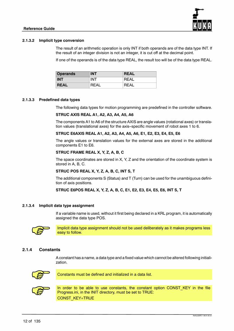
2.1.3.2 Implicit type conversion
The result of an arithmetic operation is only INT if both operands are of the data type INT. Ifthe result of an integer division is not an integer, it is cut off at the decimal point.
If one of the operands is of the data type REAL, the result too will be of the data type REAL.
Operands INT REALINT INT REALREAL REAL REAL
2.1.3.3 Predefined data types
The following data types for motion programming are predefined in the controller software.
STRUC AXIS REAL A1, A2, A3, A4, A5, A6
The components A1 to A6 of the structure AXIS are angle values (rotational axes) or transla--tion values (translational axes) for the axis--specific movement of robot axes 1 to 6.
STRUC E6AXIS REAL A1, A2, A3, A4, A5, A6, E1, E2, E3, E4, E5, E6
The angle values or translation values for the external axes are stored in the additionalcomponents E1 to E6.
STRUC FRAME REAL X, Y, Z, A, B, C
The space coordinates are stored in X, Y, Z and the orientation of the coordinate system isstored in A, B, C.
STRUC POS REAL X, Y, Z, A, B, C, INT S, T
The additional components S (Status) and T (Turn) can be used for the unambiguous defini--tion of axis positions.
STRUC E6POS REAL X, Y, Z, A, B, C, E1, E2, E3, E4, E5, E6, INT S, T
2.1.3.4 Implicit data type assignment
If a variable name is used, without it first being declared in a KRL program, it is automaticallyassigned the data type POS.
Implicit data type assignment should not be used deliberately as it makes programs lesseasy to follow.
2.1.4 Constants
Aconstant has a name, a data type anda fixed valuewhich cannot be altered following initiali--zation.
Constants must be defined and initialized in a data list.
In order to be able to use constants, the constant option CONST_KEY in the fileProgress.ini, in the INIT directory, must be set to TRUE:CONST_KEY=TRUE

2 Reference section (continued)
13 of 135
RefGuideR4.1 09.01.00 en
2.1.5 VariablesA variable has a name, a data type and a memory area in which its changeable value isstored.
2.1.5.1 System variables
The names of the KRL system variables all begin with the character “$”; this character mustnot, therefore, be used at the start of user variable names.
2.1.6 Operators
The following operators are available for the manipulation of data objects:
2.1.6.1 Arithmetic operators
Symbol Function+ Addition-- Subtraction/ Division* Multiplication
2.1.6.2 Logic operators
Symbol FunctionNOT InversionAND Logic ANDOR Logic OREXOR Exclusive OR
2.1.6.3 Relational operators
Symbol Function== Equal to< Less than> Greater than<= Less than or equal to>= Greater than or equal to<> Not equal to
2.1.6.4 Bit operators
Symbol FunctionB_NOT Bit--by--bit inversionB_AND Bit--by--bit AND operationB_OR Bit--by--bit OR operationB_EXOR Bit--by--bit exclusive OR operation
2.1.6.5 Geometric operator
Symbol Function: Performs the vector addition of frames (geometric addition)
between the data types FRAME and POS.

Reference Guide
14 of 135
RefGuideR4.1 09.01.00 en
2.1.6.6 Priority of operators
In complex expressions with more than one operator, the individual expressions areexecuted in the order of priority of the operands.
Priority Operator1 (highest) NOT, B_NOT2 *, /3 +, --4 AND, B_AND5 EXOR, B_EXOR6 OR, B_OR7 (lowest) ==, <, >, <=, >=, <>
The following rules also apply:
G Bracketed expressions are processed first.
G Non--bracketed expressions are executed in the order of priority of their operators.
G Logic operations with operators of the same priority are executed from left to right.
2.1.7 Declaration
A declaration assigns a data type to a name.
2.1.8 Initialization
Initialization assigns a value to a declaration.
2.1.9 Expression
An expression is a construction of data objects and operators with its own data type andvalue.
G An expression is arithmetic if its result has the data type INT or REAL.
G An expression is logical if its result has the data type BOOL.
G An expression is geometric if its result has the data types FRAME, POS, E6POS, AXISor E6AXIS.
2.1.10 Statement
Statements are commands which do not, in themselves, represent a fixed value and datatype. Simple statements consist of a single command line, while compound statements con--tain an entire control structure.
2.1.11 Comment
A comment is text that is ignored by the compiler. It is separated from the program code ina program line by means of the “;” character.

2 Reference section (continued)
15 of 135
RefGuideR4.1 09.01.00 en
2.1.12 Motion programming
Onespecial feature of a robot programming language is the possibility of programmingpointsbetween which the robot TCP (Tool Center Point) moves. There are two basic traversingmodes:
2.1.12.1 PTP motions (PTP = Point--To--Point)
The robot moves to the destination point with the maximum axis--specific acceleration andvelocity of the leading axis. It does not keep to a specific path.
2.1.12.2 CP motions (CP = Continuous Path)
The robot TCPmoves along a linear (LIN) or circular (CIRC) path between the start point andthe destination point. The type of motion is dependent on the programmed path velocity andacceleration, the orientation control, and, if exact positioning is not required, the nature of theapproximate positioning, as well as on the start point and destination point.
2.1.13 Control structures
Control structures are available for influencing program execution. These can be used tomake the order in which program lines are executed dependent on conditions. One exampleof this is the IF ELSE statement.
2.1.14 Subprograms
Subprograms are program code which is reached by means of branches from the mainprogram. Once the subprogram has been executed, program execution is resumed in thecommand line directly below the subprogram call.
In addition to the main program, further subprograms can also be defined in SRC files. Themain program is recognized globally if its name is the same as that of the SRC file in whichits program code is contained. If further subprograms of an SRC file are to be recognizedglobally, the keyword GLOBAL must be used.
2.1.15 Functions
Functions, like subprograms, are program units that can be called; however, they alsopossess a data type.
2.1.16 Block structure
The KRL programming language is structured in blocks. A block consists of statements,declarations, parameters and/or comments. These statements and declarations areexecuted block by block by the system.
KRL blocksmust be created in accordance with certain rules. The prescribed structure of theblocks can be noted from the syntax descriptions of the declarations and statements in theinstruction index.
A block contains either:
G a declaration
G a statement
G a comment
Empty blocks can also be used. They consist only of an end of block character.
A block begins at the start of a line without any special identifier. Blocks may also start withone or more blanks. Each block is ended by pressing the RETURN key. If blocks are too long

Reference Guide
16 of 135
RefGuideR4.1 09.01.00 en
to fit on the display, the system will automatically move onto the next line. The maximum linelength is 474 characters.
2.1.17 Areas of validity
If variables, constants, subprograms, functions or interrupts are to be globally valid, i.e.recognized in all KRL programs that are loaded, the keyword GLOBAL must be used. Thedata objects are otherwise only recognized locally, with one exception: variables declared inthe $CONFIG.DAT file are also recognized globally.
Areas of validity of local data objects:
G A local variable is valid in the program code containing the declaration of the variableand situated between the keywords DEF and ENDDEF.
G A local constant is recognized in themodule to which the data list, in which the constantwas declared, belongs.
G Local subprograms and local functions are recognized in the main program of theshared SRC file.
G A local interrupt is only recognized at, or below, the programming level in which it wasdeclared.
If there are local and global variables with the same name, the compiler uses the localvariable within its area of validity.
Global variables and constants can only be declared in data lists.
In order to be able to use the keyword GLOBAL, the global option in the file “Progress.ini”,in the INIT directory, must be set to TRUE:GLOBAL_KEY=TRUE
2.1.18 Keywords
Keywords are sequences of letters having a fixed function. They appear in bold upper--caseletters in the description of the syntax.
There are reserved and non--reserved keywords:
G Reserved keywordsmay not be used in any other way than with the meaning definedfor them. Most importantly, they must never be used as names for data objects. Someof the keywords listed in the table below are actually recognized by the compiler but arenot yet used in the system. They are thus not implemented, but reserved nevertheless.
G In the case of non--reserved keywords, the meaning is restricted to a particularcontext. This context can be identified from the description of the syntax, in which thekeyword again appears in bold upper--case letters. Outside of this context, anon--reserved keyword is interpreted as a name. To avoid any confusion, however, thenon--reserved keywords should not be used as names.

2 Reference section (continued)
17 of 135
RefGuideR4.1 09.01.00 en
The following table gives a list of all of the keywords used in the declarations, statements anddefinitions of the KRL robot programming language:
Keyword Function Brief informationANIN Statement Cyclic reading of the analog inputs.
ANOUT Statement Operator control of the analog output.
BRAKE Statement Braking of the robot motion in interruptroutines.
CASE Statement Initiates a branch in the SWITCHstatement
CCLOSE Statement Closing of channels.
CHANNEL Declaration Declaration of signal names for input andoutput channels.
CIRC Statement Circular motion.
CIRC_REL Statement Circular motion with relative targetcoordinates.
CONFIRM Statement Acknowledging of acknowledgementmessages.
CONTINUE Statement Prevention of advance run stops.
COPEN Statement Opening an input/output channel.
CREAD Statement Reading of data from channels.
CWRITE Statement Writing of data to channels.
DECL Declaration Declaration of variables and arrays.
DEF Definition Declaration of programs and subprograms.
DEFAULT Statement Initiates the default branch in the SWITCHstatement.
DEFDAT Definition Declaration of data lists.
DEFFCT Definition Declaration of functions.
DELAY Parameter Initiates the specification of the delay in theTRIGGER and ANOUT statements.
DIGIN Statement Cyclic reading in of digital inputs.
DISTANCE Parameter Initiates the specification of the switchingpoint in the TRIGGER statement
DO Statement Initiates both the call of the interruptroutine in the INTERRUPT declaration andthe call of a subprogram or an assignmentof a value in the TRIGGER statement.
ELSE Statement Initiates the second statement branch inthe IF statement.
END Statement End of a subprogram (see DEF).
ENDDAT Statement End of a data list (see DEFDAT).
ENDFCT Statement End of a function (see DEFFCT).
ENDFOR Statement Ends the FOR loop statement.

Reference Guide
18 of 135
RefGuideR4.1 09.01.00 en
ENDIF Statement Ends the IF branching.
ENDLOOP Statement Ends the LOOP.
ENDSWITCH Statement Ends the SWITCH branches.
ENDWHILE Statement Ends the WHILE loop statement.
ENUM Declaration Declaration of enumeration types.
EXIT Statement Unconditional exit from loops.
EXT Declaration Declaration of external subprograms.
EXTFCT Declaration Declaration of external functions.
FOR Statement Counting loop or initiation of the WAITstatement condition.
GLOBAL Declaration Declaration of a global area of validity.
GOTO Statement Unconditional jump statement.
HALT Statement Neatly interrupt program execution andhalt processing.
IF Statement Execution of statements depending on theresult of a logical expression.
IMPORT Declaration Imports variables from data lists.
INTERRUPT Statement Definition of an interrupt function and itsactivation and deactivation.
IS Statement Initiates the source specifications in theIMPORT declaration.
LIN Statement Linear motion.
LIN_REL Statement Linear motion with relative coordinates.
LOOP Statement Endless loop.
MAXIMUM Parameter Keyword for the maximum value of analogoutputs.
MINIMUM Parameter Keyword for the minimum value of analogoutputs.
PRIO Parameter Initiates the specification of the prioritywhen calling a subprogram in theTRIGGER statement.
PTP Statement Point--to--point motion.
PTP_REL Statement Point--to--point motion with relativecoordinates.
PULSE Statement Activation of a pulse output.
REPEAT Statement Program loop that is always executed atleast once (non--rejecting loop). Thetermination condition is checked at the endof the loop.
RESUME Statement Aborting of subprograms and interruptroutines.

2 Reference section (continued)
19 of 135
RefGuideR4.1 09.01.00 en
RETURN Statement Return from functions and subprograms.
SEC Statement Initiates the specification of the wait time inthe WAIT statement.
SIGNAL Declaration Declaration of signal names for input andoutput.
SREAD Statement Breaks a data set down into its constituentparts.
STRUC Declaration Declaration of structure types.
SWITCH Statement Choice between several statementbranches.
SWRITE Statement Combination of data to form a data set.
THEN Statement Initiates the first statement branch in the IFstatement.
TO Statement Separates initial and final values in theFOR statement and initiates thespecification of the digital inputs/outputs inthe SIGNAL declaration.
TRIGGER Statement Path--related triggering of a switchingaction synchronous to the robot motion.
UNTIL Statement Initiates the “end” inquiry in the REPEATloop
WAIT Statement Wait for a continue condition or for aspecified period of time.
WHEN Statement Initiates the logic expression in theINTERRUPT declaration and thespecification of the path--related distancecriterion in the TRIGGER statement.
WHILE Statement Program loop; termination condition ischecked at the beginning of the loop(rejecting loop).

Reference Guide
20 of 135
RefGuideR4.1 09.01.00 en
2.2 Command index
ANIN
2.2.1 ANIN
2.2.1.1 Brief information
Cyclic reading of the analog inputs.
2.2.1.2 Syntax
Reading of an analog input:
ANIN ON Signal_Value = Factor * Signal_Name �� Offset
Termination of the read operation:
ANIN OFF Signal_Name
Argument Type ExplanationSignal_Value REAL The result of the cyclical reading is stored in
Signal_Value.Signal_Value can be a variable, an analog signal or asignal declaration.
Factor REAL Factor can be a constant, variable or signal declaration.
Signal_Name REAL Signal_Name designates a signal declaration with ananalog input.
Offset REAL Offset can be a constant, variable, signal declaration oranalog signal.
All of the variables used in the ANIN statement must be declared in data lists.
A maximum of 3 ANIN ON statements may be active at any given time.
2.2.1.3 Description
The analog module makes analog interfaces available which can be read by means of thepre--defined signal variables $ANIN[1] to $ANIN[8]. The analog inputs can be read over aperiod of time using ANIN or can be assigned to a variable of data type REAL once bymeansof the operator “=”. In the case of cyclic reading with the ANIN statement, the analoginterfaces are read in the low--priority cycle (12 ms). ThreeANIN ONstatements can be usedat the same time. Two ANIN ON statements can write to the same signal value or access thesame analog interface. It is possible to combine analog inputs logically with other operatorsand to assign them to a signal value by using the optional arithmetic of the ANIN statement.
The analog module makes available 8 analog interfaces with a resolution of 12 bits(4.88 mV, not electrically isolated). The input voltage can vary from --10 V to +10 V butmaynot exceed 35 V. The hardware inputs can be assigned to interface numbers by means ofsystem parameters. Accessing an analog input triggers an advance run stop.

2 Reference section (continued)
21 of 135
RefGuideR4.1 09.01.00 en
If the input voltage exceeds 35 V, the analog module or parts of it can be destroyed.
2.2.1.4 Example
The path correction (system variable $TECHIN[1]) is to be corrected in accordance withthe sensor input $ANIN[2]. The sensor input $ANIN[2] is logically combined with thesymbolic variable SIGNAL_1. The result of multiplying the variable FACTOR and thecurrent value of SIGNAL_1 is added to the variable OFFSET and written cyclically to thesystem variable for the path correction $TECHIN[1].
SIGNAL SIGNAL_1 $ANIN[2]ANIN ON $TECHIN[1] = FACTOR * SIGNAL_1 + OFFSET
The cyclic scanning of SIGNAL_1 is ended using the ANIN OFF instruction.ANIN OFF SIGNAL_1
SIGNAL, ANOUT, DIGIN

Reference Guide
22 of 135
RefGuideR4.1 09.01.00 en
ANOUT
2.2.2 ANOUT
2.2.2.1 Brief information
Control of the analog output.
2.2.2.2 Syntax
Starting the analog output:
ANOUT ON Signal_Name = Factor * Control_Element �� Offset�DELAY = �Time�MINIMUM = Minimum_Value �MAXIMUM = Maximum_Value
Ending the analog output:
ANOUT OFF Signal_Name
Argument Type Explanation
Signal_Name REAL The Signal_Name represents a signal declaration definedusing the statement SIGNAL and referring to an analogoutput. The analog output, e.g. $ANOUT[1], must not beentered directly.
Factor REAL Factor can be a variable, signal declaration, analog signalor constant.
Control_Element
REAL Control_Element can be a variable, signal declaration oranalog signal.
Offset REAL Offset can be a variable, signal declaration, analog signalor constant.
Time REAL The Time is specified in seconds as a real number.
Minimum_Value,Maximum_Value
REAL Minimum_Value and Maximum_Value must be between--1.0 and +1.0 and limit the output. The actual value doesnot fall below/exceed the specified minimum/maximumvalues, even if the calculated values fall outside thisrange. The minimum value must, of course, always beless than the maximum value and the keyword sequenceMINIMUM MAXIMUM must be maintained.
All of the variables used in the ANOUT statement must be declared in data lists.
2.2.2.3 Description
Unlike the binary or digital output, the analog output is not controlled simply by means of asimple value assignment but bymeans of the ANOUT statement. The signal name is definedusing the SIGNAL command.

2 Reference section (continued)
23 of 135
RefGuideR4.1 09.01.00 en
The expression that can be specified for calculating the value of the analog output iscalculated cyclically. It must not, however, be too extensive, so that it can be calculatedwithinthe cycle time. The result of the expression must be in the range --1 to +1 or 0 to +1,corresponding to the configuration of the hardware. If the result of the expression exceedsthese limits, the output takes the relevant final value and thehintmessage “Limit signal name”is displayed until the result falls below these limits again. The keywords MINIMUM andMAXIMUM can be used, however, to define lower output limit values.
The optional keywordDELAY can be used to program positive or negative delays. The valueof the delay is specified in seconds as a real number.
The robot controller provides 16 analog outputs ($ANOUT[1] ... $ANOUT[16]) as standard.The analog outputs can be read and set.
2.2.2.4 Example
The analog output $ANOUT[5] is assigned to the symbolic name ANALOG_1. When theanalog value output is activated, the product of the variable FACTOR and the systemvariable $TECHVAL[1], increased by the value of the variable OFFSET_1, is cyclicallycalculated and written to the analog output $ANOUT[5]. The analog output is ended usingANOUT OFF ANALOG_1.Please note: in order for $TECHVAL[i] to provide an unfiltered signal corresponding to thetechnology--specific function, $TECH_ANA_FLT_OFF[i] must be set to TRUE.
SIGNAL ANALOG_1 $ANOUT[5]ANOUT ON ANALOG_1 = FACTOR * $TECHVAL[1] + OFFSET_1...ANOUT OFF ANALOG_1
The analog output $ANOUT[1] is assigned to the symbolic nameADHESIVE for controllingthe dispensing of adhesive in proportion to the velocity. The control value is calculated fromhalf of the path velocity (system variable $VEL_ACT; in order to obtain an uncorruptedsignal proportional to the path velocity, $VEL_FLT_OFF must have the value TRUE) anda constant addition of 0.2. Output of the cyclically calculated output signal is delayed for0.05 seconds using the optional parameter DELAY. The analog output is ended by usingANOUT OFF ADHESIVE.
SIGNAL ADHESIVE $ANOUT[1]ANOUT ON ADHESIVE = 0.5*$VEL_ACT + 0.2 DELAY = 0.05...ANOUT OFF ADHESIVE
ANIN, SIGNAL

Reference Guide
24 of 135
RefGuideR4.1 09.01.00 en
BRAKE
2.2.3 BRAKE
2.2.3.1 Brief information
Braking of the robot motion in interrupt routines.
2.2.3.2 Syntax
BRAKE �F
Argument Type ExplanationF Specifying the parameter F (brake fast) causes the robot
to be braked with increased deceleration, just like in anEmergency Stop. If the path--maintaining stop isconfigured for the selected operating mode using themachine data $EMSTOP_PATH, the robot is braked onthe path in a time--optimal manner. Otherwise, the axesare only braked in a synchronized manner, leaving thepath.
2.2.3.3 Description
The BRAKE statement is used in an interrupt routine to brake the robot motion that it stillactive. BRAKE brakes the motion with the same deceleration as with an operator stop.Braking using the BRAKE statement occurs on the programmed path if the argument F is notspecified.
The interrupt routine is not continued until the robot has come to a stop.
The BRAKE statement must not be used outside interrupt routines. Failure toobserve this will cause execution of the program to be aborted.
2.2.3.4 Example
A non--path--maintaining Emergency Stop is executed via the hardware during applicationof adhesive. You would now like to use the program to stop application of the adhesive andreposition the adhesive gun onto the path after enabling (by input 10).
DEF STOPSP(); Interrupt routineBRAKE FADHESIVE = FALSEWAIT FOR $IN[10]LIN $POS_RET; Move gun to position at which the path was leftADHESIVE = TRUEEND
INTERRUPT DECL, INTERRUPT

2 Reference section (continued)
25 of 135
RefGuideR4.1 09.01.00 en
CCLOSE
2.2.4 CCLOSE
2.2.4.1 Brief information
Input/output channels that have previously been declared with the “CHANNEL” statementcan be closed using the “CCLOSE” statement. “CCLOSE” deletes all of the data that arewaiting to be read. When deselecting and resetting a program, all of the channels that areopen there are closed.
2.2.4.2 Syntax
CCLOSE (Handle, State)
Argument Type Explanation
Handle INT The “handle” variable transferred by “COPEN”.
State STATE_T “CMD_STAT” is an enumeration type which is the firstcomponent of the State variable of the structure type“STATE_T”. Values of the component “CMD_STAT” thatare relevant for “CCLOSE” are:CMD_OK Command successfully executedCMD_ABORT Command not successfully executed
2.2.4.3 Description
Input/output channels that have previously been declared with the “CHANNEL” statementcan be closed using the “CCLOSE” statement.
Possible causes of “CMD_ABORT” are:
The channel
-- is already closed;
-- HANDLE not valid;
-- has been opened by another process.
The “HANDLE” can no longer be used for channel statements once this function has beencalled successfully. The value of the variable is not changed, however.“CCLOSE” deletes all of the data that are waiting to be read. When deselecting andresetting a program, all of the channels that are open there are implicitly closed.
The complete definition of the status and mode information for channel statements canbe found in the chapter “CHANNEL”.
2.2.4.4 Example
Closing of a channel with the handle “HANDLE”. The status variable “SC_T” returns informa--tion about the status.
CCLOSE(HANDLE,SC_T)

Reference Guide
26 of 135
RefGuideR4.1 09.01.00 en
A complete example of a program can be found in the chapter “CHANNEL”.

2 Reference section (continued)
27 of 135
RefGuideR4.1 09.01.00 en
CHANNEL
2.2.5 CHANNEL
2.2.5.1 Brief information
The “CHANNEL” statement is used for declaring signal names for input and output channels.
2.2.5.2 Syntax
CHANNEL :Channel_Name: Interface_Name Structure_Variable
Argument Type Explanation
Channel_Name Any symbolic name
Interface_Name Predefined signal variableSER_1 serial interface 1SER_2 serial interface 2
Structure_Variable System--dependent structure variablespecifying the protocol. Evaluation is notcarried out.
2.2.5.3 Description
The robot controller contains two classes of interface:
G simple process interfaces -- signals -- and
G logic interfaces -- channels.
All of the interfaces are addressed using symbolic names. The specific interface names(symbolic names) are logically combined with the predefined signal variables for channelsby means of the CHANNEL declaration.
The predefined signal variables for channels are
G SER_1 and
G SER_2
for the serial interfaces, and
G $CMD (e.g. “RUN....”)
for the command interpreter.
The procedure for accessing channels is the same. In order to be able to access a channel,it must be declared in the “CHANNEL” declaration.
The variables are predefined in the file “$CUSTOM.DAT” (directory “....\PROGRAMFILES\KRC\MADA\STEU”) “:SER_1” and “:SER_2”.
The channel can then be opened with the “COPEN” statement. The “CREAD” statement canbe used to read the channel, while the “CWRITE” statement is used to write to the channel.The channel is closed with the “CCLOSE” statement.
The state and mode information for channel statements are the same.
The state information is returned in a variable of the predefined structure type “STATE_T”.“STATE_T” has the following definition:

Reference Guide
28 of 135
RefGuideR4.1 09.01.00 en
STRUC STATE_T CMD_STAT RET1, INT HITS, INT LENGTH
“CMD_STAT” is a predefined enumeration type of the following form:
ENUM CMD_STAT CMD_OK, CMD_TIMEOUT, DATA_OK, DATA_BLK, DATA_END,CMD_ABORT, CMD_REJ, CMD_PART, CMD_SYN, FMT_ERR
The modes that can be used with the statements “CREAD” and “CWRITE” are madeavailable as a predefined enumeration type:
ENUM MODUS_T SYNC, ASYNC, ABS, COND, SEQ
The meaning of the state and mode are explained in the sections on the individualcommands. Only the parameters listed there are used.
2.2.5.4 Example
Assignment of a channel name to a physical channel
With the “CHANNEL” statement:Channel name :SER_2
is assigned tophysical channel :SER_2
predefined in the file “$CUSTOM.DAT”(directory ....\PROGRAM FILES\KRC\MADA\STEU)
CHANNEL :SER_2 :SER_2 $PSER_2
SIGNAL, COPEN, CCLOSE, CREAD, CWRITE

2 Reference section (continued)
29 of 135
RefGuideR4.1 09.01.00 en
CIRC
2.2.6 CIRC
2.2.6.1 Brief information
Programming a circular motion.
2.2.6.2 Syntax
CIRC Auxiliary_Point, Target_Position �,CA Circular_Angle�Path_Approximation
Argument Type ExplanationAuxiliary_Point
POS,E6POS,FRAME
Geometric expression producing an auxiliary pointon the circular path. Only Cartesian coordinates canbe used here.
The reference system for the Cartesian auxiliaryposition is defined by the system variable $BASE.
The orientation angles and the angle statusspecifications S and T for an auxiliary point arealways disregarded.
If structure components are missing in the auxiliarypoint, these values are taken unchanged from thecurrent position.
Target_Position
POS,E6POS,FRAME
Geometric expression specifying the target positionof the circular motion. Only Cartesian coordinatescan be used here.
The reference system for the Cartesian targetposition is defined by the system variable $BASE.
The angle status specifications S and T for a targetposition of type POS or E6POS are alwaysdisregarded. If structure components are missing inthe target position, these values are takenunchanged from the current position.
! The auxiliary point and the target point can also betaught. If this is to be done later, a “!” is programmedin the place of the auxiliary point and target position.

Reference Guide
30 of 135
RefGuideR4.1 09.01.00 en
Circular_Angle
REAL Arithmetic expression allowing the arc to belengthened or shortened in conjunction with thekeyword CA (circular angle). The unit ofmeasurement is degrees. There is no limit for thecircular angle. In particular, a circular angle greaterthan 360 can be programmed.
If the circular angle is positive, the robot movesalong the circular path in the direction defined by thestart position, the auxiliary point and the targetposition. If it is negative, the robot moves along thecircular path in the opposite direction.
When specifying a circular angle, the programmedtarget position is not generally the real targetposition. This is defined by the angle specification.
Approximate_Positioning
Keyword This option allows you to use approximatepositioning. The possible entries are:
C_DIS (default value) C_ORI C_VEL
Programming the path velocity and acceleration of the TCP:
Variable Data type Unit FunctionVelocities $VEL.CP REAL m/s Travel speed (path
velocity)$VEL.ORI1 REAL /s Swivel velocity$VEL.ORI2 REAL /s Rotational velocity
Accelerations $ACC.CP REAL m/sΟ Path acceleration$ACC.ORI1 REAL /sΟ Swivel acceleration$ACC.ORI2 REAL /sΟ Rotational acceleration
Orientation control of the tool with CIRC motions:
Variable Effect$ORI_TYPE = #CONSTANT During the path motion the orientation remains
constant; the programmed orientation is ignored forthe destination point and that for the start point used.
$ORI_TYPE = #VAR During the path motion the orientation changescontinuously from the initial orientation to thedestination orientation.
$CIRC_TYPE = #BASE Orientation control relative to the base system($BASE).
$CIRC_TYPE = #PATH Orientation control relative to the tool--basedmovingframe on the circular path.

2 Reference section (continued)
31 of 135
RefGuideR4.1 09.01.00 en
System variables for defining the start of approximate positioning:
Variable Data type Unit Meaning Keyword inthe command
$APO.CDIS REAL mm Translational distancecriterion
C_DIS
$APO.CORI REAL Orientation distance C_ORI$APO.CVEL INT % Velocity criterion C_VEL
2.2.6.3 Description
In the case of CIRC motions, the controller calculates a circular motion from the currentposition via an auxiliary point to an end point, which is thus unambiguously determined bythe target position or the circular angle. The robot is moved to the end point via intermediatepoints, which are calculated and executed at intervals of one interpolation cycle.
Just as for LIN motions, both the velocities and accelerations and the system variables$TOOL and $BASE must also be programmed for circular motions. However, the velocitiesand accelerations no longer refer to themotor speed of each axis but to the TCP. The systemvariables
G $VEL for the path velocity and
G $ACC for the path acceleration
are available for defining them.
Orientation control
G Space--related or path--related orientationYou can basically choose between space--related and path--related orientation control.In the case of space--related orientation control, the orientation is interpolated relativeto the current base system ($BASE); with path--related orientation, on the other hand,it is interpolated relative to the tool coordinate system (tool--based moving frame). Thetype of orientation control is defined with the aid of the system variable $CIRC_TYPE:
-- $CIRC_TYPE=#BASE for space--related orientation control and
-- $CIRC_TYPE=#PATH for path--related orientation control.
G Variable and constant orientationYou can also choose between variable and constant orientation. If you select variableorientation, this means that the change in orientation which occurs between the startposition and the programmed target position is taken into account. It is executed eitherin relation to space or in relation to the path. In the case of constant space--relatedorientation, the orientation at each control point is absolutely identical to the orientationat the start point. With constant path--related orientation, the relative orientation isconstant in relation to the tool--basedmoving frame. If an orientation has been specifiedfor the target position, this is disregardedwith constant orientation. The system variable$ORI_TYPE is used for defining the orientation:
-- $ORI_TYPE=#VAR for variable orientation and
-- $ORI_TYPE=#CONSTANT for constant orientation control.
Angle status
In the case of CIRC motions, the angle status of the end point is always the same as that ofthe start point. For this reason, the specifications Status S and Turn T for a target positionof data type POS or E6POS are always disregarded.

Reference Guide
32 of 135
RefGuideR4.1 09.01.00 en
In order to alwaysensure an identicalmotion sequence, the constellationof the axesmust first be unambiguously defined. The firstmotion instruction of a programmusttherefore always be a PTP instruction specifying S and T.
Approximate positioning
It is unnecessary and time--consuming to position the robot exactly to auxiliary points. Youcan therefore start a transition to the following motion block (PTP, LIN or CIRC) at a defineddistance from the target position (so--called approximate positioning).Approximate positioning is programmed in two steps:
G Definition of the approximate positioning range with the aid of the system variable$APO:
-- $APO.CDIS:translational distance criterion (activated by C_DIS):the approximate positioning contour is started at a specified distance (unit [mm])from the target point.
-- $APO.CORI:orientation distance (activated by C_ORI): the TCP leaves the individual blockcontour when the dominant orientation angle (swiveling or rotation of thelongitudinal axis of the tool) falls below the specified angle distance to the targetpoint.
-- $APO.CVELvelocity criterion (activated by C_VEL): when the $APO.CVEL percentage of thevelocity defined in $VEL.CP is achieved, the approximate positioning contour isinitiated. A maximum of half the programmed distance may be approximated.
G Programming of the motion instruction with a target position and an approximatepositioning mode:
-- CIRC--CIRC or CIRC--LIN approximate positioningIn the case of CIRC--CIRC and CIRC--LIN approximate positioning, a symmetricalapproximate positioning contour cannot be calculated. The approximatepositioning path consists of two parabolic segments, which also have a tangentialtransition between each other and also to the individual blocks. To define whereapproximate positioning is to begin and end, one of the keywords C_DIS, C_ORIor C_VEL has to be programmed.
-- CIRC--PTP approximate positioningA precondition for approximate positioning is that none of the robot axes rotatesmore than 180 in the CIRC block and that the position S does not change. Thestart of approximate positioning is defined by one of the variables $APO.CDIS,$APO.CORI and $APO.CVELand the endby the variable $APO.CPTP.One of thekeywords C_DIS, C_ORI and C_VEL has to be programmed in the CIRCinstruction.

2 Reference section (continued)
33 of 135
RefGuideR4.1 09.01.00 en
For approximate positioning, the computer advance runmust be enabled. If it is not,the message “Approximation not possible” will be displayed. In the case ofCIRC--PTP approximate positioning, the advance run is limited to 1, however!
G Programstatements that stop the advance runmaynot appear betweenapproximatepositioning blocks (remedy with CONTINUE).
G The greater the velocity and acceleration are, the greater the dynamic deviationsfrom the path will be (following error).
G Changing the acceleration has a considerably lesser effect on the path contour thanchanging the velocity.
G Interpolation is always carried out on a space--related basis in the approximatepositioning range.
G The initial orientation for approximate positioning is always the orientation that wouldbe achieved at the approximate positioning point relative to the base.
G If twoCIRCblocks are executedwith path--related orientation, the reorientation in theapproximate positioning range is nevertheless space--related.
2.2.6.4 Example
Circular motion with taught auxiliary and target coordinates.CIRC !
Circular motion with taught auxiliary and target coordinates; the target point of themotion is determined by the circular angle of --35.CIRC ! ,CA -35
Circular motion with programmed auxiliary and target coordinates.CIRC {X 5,Y 0, Z 9.2},{X 12.3,Y 0,Z -5.3,A 9.2,B -5,C 20}
Circular motion with programmed auxiliary and target coordinates; approximatepositioning is activated.CIRC {Z 500,X 123.6},POINT1,CA +260 C_ORI
Constant path--related orientation control.$ORI_TYPE=#CONSTANT$CIRC_TYPE=#PATHCIRC AUX_POINT,{X 34, Y 11, Z 0}
CIRC--PTP approximate positioning from point 2 to point 3. Approximate positioning isstarted 30 mm before point 2.$APO.CDIS=30$APO.CPTP=20PTP POINT1CIRC AUX_POINT,POINT2,CA ANGLE C_DISPTP POINT3
CIRC_REL, PTP, LIN, CONTINUE

Reference Guide
34 of 135
RefGuideR4.1 09.01.00 en
CIRC_REL
2.2.7 CIRC_REL
2.2.7.1 Brief information
Circular motion with relative coordinates.
2.2.7.2 Syntax
CIRC_REL Auxiliary_Point,Target_Position�,CA Circular_Angle�Approximate_Positioning
Argument Type ExplanationTarget_Position
POS,E6POS,FRAME
Geometric expression specifying the target positionof the circular motion. Only Cartesian coordinatescan be used here. These are to be interpretedrelative to the current position before the CIRCmotion.
Translational distances are executed in the directionof the axes of the base coordinate system $BASE.
If the target position contains undefined structurecomponents, these values are set to 0, i.e. theabsolute values remain unchanged.
The predefined variable $ROTSYS defines the effectof the programmed orientation components.
The angle status specifications S and T for a targetposition of type POS or E6POS are alwaysdisregarded.

2 Reference section (continued)
35 of 135
RefGuideR4.1 09.01.00 en
Auxiliary_Point
POS,E6POS,FRAME
Geometric expression producing an auxiliary pointon the circular path. The auxiliary point is to bespecified in relative and Cartesian coordinates!
Translational distances are executed in the directionof the axes of the base coordinate system $BASE.
If the auxiliary point contains undefined structurecomponents, these values are set to 0, i.e. theabsolute values remain unchanged.
The predefined variable $ROTSYS defines the effectof the programmed orientation components.
The orientation angles and the angle statusspecifications S and T for an auxiliary point arealways disregarded.
Circular_Angle
REAL Arithmetic expression allowing the arc to belengthened or shortened in conjunction with thekeyword CA (circular angle). The unit ofmeasurement is degrees.
There is no limit for the circular angle. In particular, acircular angle greater than 360 can beprogrammed.
If the circular angle is positive, the robot movesalong the circular path in the direction defined by thestart position, the auxiliary point and the targetposition. If it is negative, the robot moves along thecircular path in the opposite direction.
When specifying a circular angle, the programmedtarget position is not generally the real targetposition. This is defined by the angle specification.
Approximate_Positioning
Keyword This option allows you to use approximatepositioning. The possible entries are:
C_DIS (default value) C_ORI C_VEL

Reference Guide
36 of 135
RefGuideR4.1 09.01.00 en
Programming the path velocity and acceleration of the TCP:
Variable Data type Unit FunctionVelocities $VEL.CP REAL m/s Travel speed (path
velocity)$VEL.ORI1 REAL /s Swivel velocity$VEL.ORI2 REAL /s Rotational velocity
Accelerations $ACC.CP REAL m/sΟ Path acceleration$ACC.ORI1 REAL /sΟ Swivel acceleration$ACC.ORI2 REAL /sΟ Rotational acceleration
Orientation control of the tool with CIRC motions:
Variable Effect$ORI_TYPE = #CONSTANT During the path motion the orientation remains
constant; the programmed orientation is ignored forthe destination point and that for the start point used.
$ORI_TYPE = #VAR During the path motion the orientation changescontinuously from the initial orientation to thedestination orientation.
$CIRC_TYPE = #BASE Orientation control relative to the base system($BASE).
$CIRC_TYPE = #PATH Orientation control relative to the tool--basedmovingframe on the circular path.
System variables for defining the start of approximate positioning:
Variable Data type Unit Meaning Keyword inthe command
$APO.CDIS REAL mm Translational distancecriterion
C_DIS
$APO.CORI REAL Orientation distance C_ORI$APO.CVEL INT % Velocity criterion C_VEL
2.2.7.3 Description
The relative CIRC instruction basically works in exactly the same way as the absolute CIRCinstruction. The target coordinates are merely defined relative to the current position insteadof with the aid of absolute space or axis coordinates.Apart from this, all the information contained in the description of the absolute CIRCinstruction applies here.

2 Reference section (continued)
37 of 135
RefGuideR4.1 09.01.00 en
2.2.7.4 Example
Circular motion with programmed auxiliary and target coordinates; the target point of themotion is defined by a circle angle of 500; approximate positioning is activated.CIRC_REL {X 100,Y, 3.2,Z -20},{Y 50},CA 500 C_VEL
LIN--CIRC approximate positioning from point 1 to point 2 and CIRC--CIRC approximatepositioning from point 2 to point 3. Approximate positioning to point 1 is started when thevelocity has been reduced to 0.6 m/s (50% of 1.2 m/s). Approximate positioning to point2 begins 20 mm before point 2.$VEL.CP=1.2$APO.CVEL=50$APO.CDIS=20LIN POINT1 C_VELCIRC_REL AUX_POINT,POINT2_REL C_DISCIRC AUX_POINT,POINT3
CIRC, PTP_REL, LIN_REL, CONTINUE

Reference Guide
38 of 135
RefGuideR4.1 09.01.00 en
CONFIRM
2.2.8 CONFIRM
2.2.8.1 Brief information
Acknowledging of acknowledgement messages.
2.2.8.2 Syntax
CONFIRM Management_Number
Argument Type ExplanationManagement_Number
INT Arithmetic expression specifying the managementnumber of the message that is to be acknowledged.
Specifying the management number 0 means that allof the messages that can be acknowledged areacknowledged.
2.2.8.3 Description
Acknowledgement messages can be acknowledged under program control using thestatement CONFIRM. After a message has been successfully acknowledged, it is no longerpresent.

2 Reference section (continued)
39 of 135
RefGuideR4.1 09.01.00 en
2.2.8.4 Example
Acknowledgement of the acknowledgement message with the number 27.CONFIRM 27
Acknowledgement of the acknowledgement message with the number M_NUMBER.CONFIRM M_NUMBER
Acknowledgement of the acknowledgement message with the number M_NUMBER+5.CONFIRM M_NUMBER+5
Acknowledgement of all existing acknowledgement messages.CONFIRM 0
After a stop signal (e.g. Emergency Stop) has been canceled, an acknowledgementmessage is always displayed. This must be acknowledged first before you can work anyfurther. The following subprogram detects and acknowledges this messageautomatically, provided that the correct operating mode (not manual operation) isselected and that the stop state has really been canceled. As a robot program cannotbe started if an acknowledgement message is active, the subprogram must be locatedin a Submit file.DEF AUTO_QUIT()INT MDECL STOPMESS MESSAGE ; Predefined structure type for stop messagesIF $STOPMESS AND $EXT THEN ; Check stop message and operating mode
M=MBX_REC($STOPMB_ID,MLD); Read current state into MESSAGEIF M==0 THEN ; Check that message may be acknowledged
IF ((MESSAGE.GRO==2) AND (MESSAGE.STATE==1)) THENCONFIRM MLD.CONFNO; Acknowledgement of this message
ENDIFENDIF
ENDIFEND

Reference Guide
40 of 135
RefGuideR4.1 09.01.00 en
CONTINUE
2.2.9 CONTINUE
2.2.9.1 Brief information
Prevention of advance run stops.
2.2.9.2 Syntax
CONTINUE
2.2.9.3 Description
You canuse the systemvariable $ADVANCE to define howmanymotion blocks the controllerexecutes in advance. In the case of instructions concerning the periphery (e.g. input/outputinstructions), the computer advance run is always stopped, however. If you do not want thisto happen, the CONTINUE statement must be programmed before the relevant instruction.
TheCONTINUE statement always only applies to the following instruction line, evenif this is a blank line!
2.2.9.4 Example
Prevention of an advance run stop with $OUT:CONTINUE$OUT[1]=TRUECONTINUE$OUT[2]=FALSE
ANOUT, HALT, WAIT, PULSE

2 Reference section (continued)
41 of 135
RefGuideR4.1 09.01.00 en
COPEN
2.2.10 COPEN
2.2.10.1 Brief information
Input/output channels that have previously been declared with the “CHANNEL” statementcan be opened using the “COPEN” statement.
2.2.10.2 Syntax
COPEN (Channel_Name, Handle)
Argument Type Explanation
Channel_Name Channel name declared in the “CHANNEL”statement.
Handle INT User--defined variable
2.2.10.3 Description
Input/output channels that have previously been declared with the CHANNEL statement canbe opened using the “COPEN” statement – which may be included in programs at control orrobot levels.
The “Handle” variable identifies the relevant channel for all of the following accesses. If thesystem refuses to open a channel, a 0 is returned.
The predefined variable “$CMD” is available for command execution, which is generallyopen.
2.2.10.4 Example
Opening of a channel with the declared channel name “:SER_2” and the handle“HANDLE”.
COPEN(:SER_2,HANDLE)
A complete example of a program can be found in the chapter “CHANNEL”.

Reference Guide
42 of 135
RefGuideR4.1 09.01.00 en
CREAD
2.2.11 CREAD
2.2.11.1 Brief information
Reading of data from channels.
Application example: Data exchange (read statement) between KR C1 and apartner device (PC, intelligent sensor ...).
The “CREAD” statement is used for reading data from open channels. Two cases aredistinguished here:
G Active readingThe program requests an input via a channel. The channel drivers set an input requestand return the data that are received to the CREAD statement as a result.
G Passive readingA predefined variable (INT $DATA_SER1 or INT $DATA_SER2), which is incrementedby the channel driver after the arrival of unrequested data, is made available for eachof the channels “:SER_1” and “:SER_2”. The variables are initialized with 0 when awarm restart is carried out or when a channel is opened or closed.There are also differences in the way that the system waits for the feedback signal ofa read request: absolutely or conditionally. Absolutely means that the systemwaits untilthe channel provides the data requested. In the case of conditional waiting, the systemchecks whether data are available.
2.2.11.2 Syntax
CREAD (Handle, State, Mode, Timeout, Offset, Format,Var1,..., VarN)
Argument Type Explanation
Handle INT The handle variable transferred by “COPEN”.Note: the variable “$CMD” will be rejected!
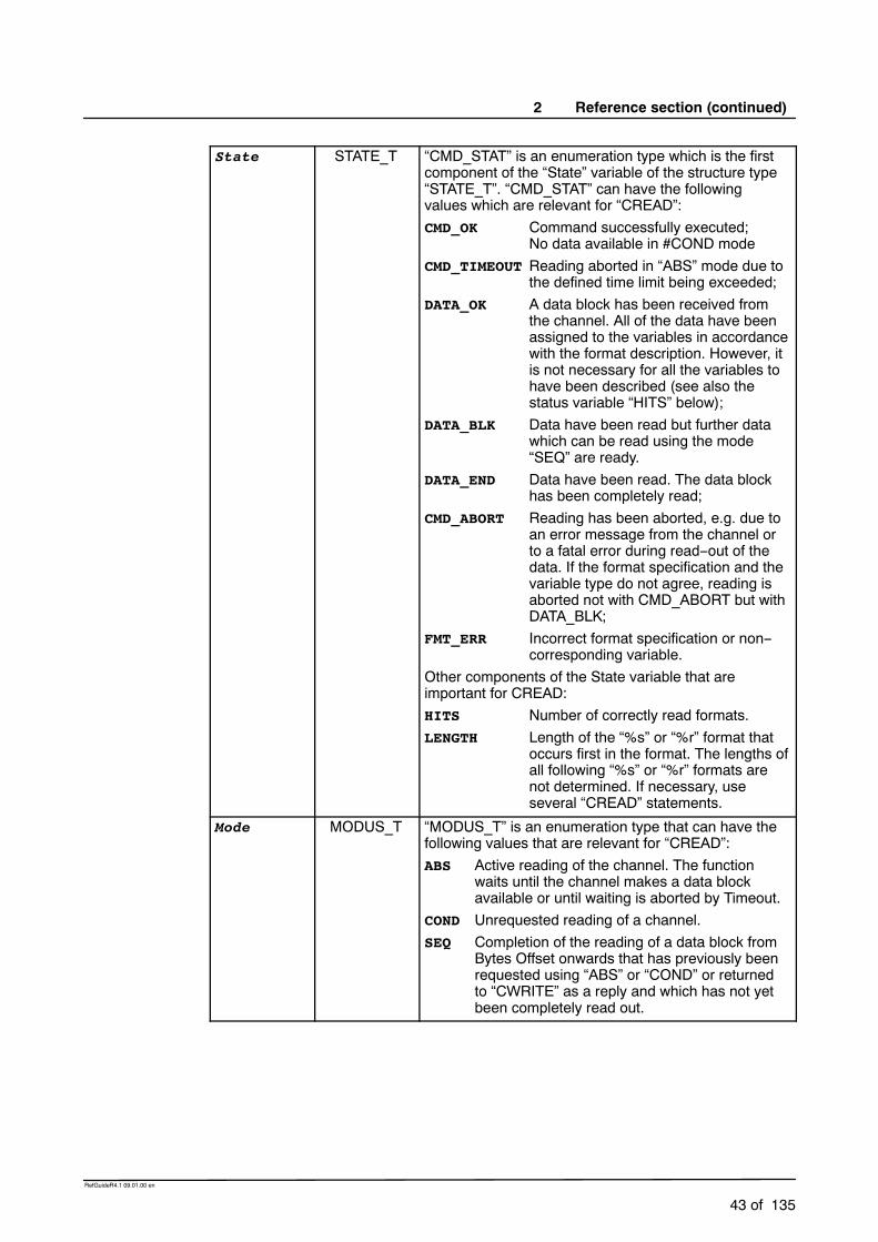
2 Reference section (continued)
43 of 135
RefGuideR4.1 09.01.00 en
State STATE_T “CMD_STAT” is an enumeration type which is the firstcomponent of the “State” variable of the structure type“STATE_T”. “CMD_STAT” can have the followingvalues which are relevant for “CREAD”:CMD_OK Command successfully executed;
No data available in #COND modeCMD_TIMEOUT Reading aborted in “ABS” mode due to
the defined time limit being exceeded;DATA_OK A data block has been received from
the channel. All of the data have beenassigned to the variables in accordancewith the format description. However, itis not necessary for all the variables tohave been described (see also thestatus variable “HITS” below);
DATA_BLK Data have been read but further datawhich can be read using the mode“SEQ” are ready.
DATA_END Data have been read. The data blockhas been completely read;
CMD_ABORT Reading has been aborted, e.g. due toan error message from the channel orto a fatal error during read--out of thedata. If the format specification and thevariable type do not agree, reading isaborted not with CMD_ABORT but withDATA_BLK;
FMT_ERR Incorrect format specification or non--corresponding variable.
Other components of the State variable that areimportant for CREAD:HITS Number of correctly read formats.LENGTH Length of the “%s” or “%r” format that
occurs first in the format. The lengths ofall following “%s” or “%r” formats arenot determined. If necessary, useseveral “CREAD” statements.
Mode MODUS_T “MODUS_T” is an enumeration type that can have thefollowing values that are relevant for “CREAD”:ABS Active reading of the channel. The function
waits until the channel makes a data blockavailable or until waiting is aborted by Timeout.
COND Unrequested reading of a channel.SEQ Completion of the reading of a data block from
Bytes Offset onwards that has previously beenrequested using “ABS” or “COND” or returnedto “CWRITE” as a reply and which has not yetbeen completely read out.

Reference Guide
44 of 135
RefGuideR4.1 09.01.00 en
Timeout REAL The parameter “Timeout” can be used to specify a timein seconds, after which the wait for a data block isaborted. A Timeout with the value 0.0 corresponds toan endless wait.A value over 60 or negative values are rejected. Asystem--related inaccuracy is inherent in the wait time.
Offset INT The variable “Offset” is used to specify the number ofbytes in the data that have been received after whichthe system is to start reading. If reading is to start fromthe beginning, Offset must be set to 0 (zero).After a “CREAD” statement that does not assign all ofthe data received to program variables, Offset specifiesthe number of characters that have been assigned sofar.
Format CHAR[ ] The variable “Format” of the type “CHAR[ ]” (Textstring)contains the format of the text that is to be generated.The structure of the variable largely corresponds to theformat string of the function “FPRINTF” of the “C”programming language.
Var The variables corresponding to “Format”.
2.2.11.3 Description
The “CREAD” statement is used for reading data from open channels. Two cases aredistinguished here:
G Active readingThe program requests an input via a channel. The channel drivers set an input requestand return the data that are received to the CREAD statement as a result.
G Passive readingAnother partner has written data to a channel without being requested to and expectsthe data to be collected. A predefined variable is made available for each of thechannels “SER_1” and “SER_2”.
INT $DATA_SER1 orINT $DATA_SER2,
and these are incremented by the channel driver after the arrival of unrequested data.The variables are initialized with 0 (zero) when the system is started or when a channelis opened or closed.
There are also differences in the way that the system waits for the feedback signal of a readrequest. The “CREAD” statement can wait absolutely or conditionally.
-- Absolutelymeans that the system waits until the channel provides the data of thetype requested.
-- In the case of conditional waiting, the system checks whether data are available.
By using the feedback signal, it can be determined whether the read statement wassuccessful or not. The relevant procedure is defined by the parameter “Mode”.
If a Handle that does not come from a “COPEN” statement of the process is transferred inthe “CREAD” statement or if the channel has already been closed again, theacknowledgment message “INVALID HANDLE” is displayed.

2 Reference section (continued)
45 of 135
RefGuideR4.1 09.01.00 en
The specification of other modes or of non--initialized variables causes an error to bedetected in the variable “Status”. If reading with “ABS” oder “COND” is successful, the dataof the data block that was previously received are overwritten, even if they have not yetbeen completely read out.The text that is returned is segmented in accordance with the format specification. Thevalues that are determined are assigned to the appropriate variables, with the systemchecking whether the value is valid for each variable. A conversion specification for thevariable “Format” supports the formats described in Kernighan/Ritchie (The CProgramming Language, Prentice Hall, 1978), with the exception of o, p, n, u and [list].The length specifications “H” and “L” may not be used.Only 9 format parameters may be specified in a CREAD statement.If several variables are available for formatting, the read--in must be continued in #SEQmode.The system cannot distinguish between upper and lower--case letters. Read--in is abortedafter the occurrence of the first error (unsuitable format or invalid value).The conversion character “R”, which reads in either a byte sequence of the specified length(similar to with writing, e.g. “%2.5r”) or all bytes up to the end of the message, is alsointroduced.Unlike the other formats, the reading of an individual byte must be explicitly stated using“%1r”.There is no point specifying a width with the format “%c”; such a specification is thereforerejected. The byte sequence can be assigned to a sufficiently large variable of type INT,REAL, CHAR, BOOL, ENUM or to one--dimensional arrays of these types.It is assumed that integer data appear in “little endian” format and are signed.Data of type Real must be in 32--bit representation in IEEE 754 standard format
bit 31 sign,bit 30--23 exponent,bit 22-- 0 mantissa.

Reference Guide
46 of 135
RefGuideR4.1 09.01.00 en
The types and values are checked in accordance with the following table at run time:
Format
Variable
%d
%i
%x
%f
%e
%g
%c %s %1r
(3)
%1.
hWDHi
r
%2r
(3)
%2.
hWDHi
r
%4r(3)
%4.
hWDHi
r
(4)
%r
(3)
%.
hWDHi
r
(Signal)INT
X -- X -- X -- X -- X -- X --
INT array -- -- -- -- -- X -- X -- X X X
REAL X X -- -- -- -- -- -- X -- X --
REALarray -- -- -- -- -- -- -- -- -- X X X
(Signal)BOOL (1) X -- X -- X -- X -- X -- X --
BOOLarray -- -- -- -- -- X -- X -- X X X
ENUM (2) X -- X -- X -- X -- X -- X --
ENUMarray -- -- -- -- -- X -- X -- X X X
CHAR X -- X -- X -- -- -- -- -- X --
CHARarray -- -- -- X -- X -- -- -- -- X X
Remarks
G Every value that is not equal to 0 (zero) is converted to TRUE
G The system checks whether the value is a permissible ENUM value. If it is not, readingis aborted. ENUM begins at 1.
G If there are not enough data available to satisfy the requirements of the format (e.g.%2.5r, but only 7 bytes are present), nothing is read for this format and the CREADstatement is aborted. The ignored data are, however, still ready for reading.
G Only as many bytes as can fit into the variable are read. The rest are still ready forreading. If the array is actually big enough but the number of available bytes is not amultiple of the size of an array element, the redundant bytes for the following format orfor the next CREAD statement are left for reading.
A message that is not completely read can be read further by the following “CREAD” calls.The number of bytes of the “%s” or “%r” format specified first in the format string that haveactually been read is returned in the status variable.
All of the other lengths are not determined. It is therefore advisable to use “%s” and “%r”formats only once in a format string and to repeat the “CREAD” call.
If the “%s” or “%r” format is not among the formats that have been successfully read (see“HITS” of the variable State), the value of “LENGTH” is not changed by the statement.

2 Reference section (continued)
47 of 135
RefGuideR4.1 09.01.00 en
Particularly time--intensive input and output operations can have a considerable effect onprogram execution.The following applies to all statements:-- A statement always waits until it is completely finished and then returns to the program.This is particularly important for the absolute CREAD statement for reading to textchannels.
-- Regardless of this, these statements can be interrupted by interrupt programs. Anyattempts to access channels there can only be interrupted by other interruptsubprograms.
The complete definitions of the status and mode information for channel instructions canbe found in the “CHANNEL” declaration. See Section 2.2.5.
A complete example of a program can be found in the chapter “CHANNEL”.

Reference Guide
48 of 135
RefGuideR4.1 09.01.00 en
CWRITE
2.2.12 CWRITE
2.2.12.1 Brief information
The “CWRITE” statement enables texts to be written to an open channel, or commands tobe written to a command channel.
Application example: Data exchange (write statement) between KR C1 and a partnerdevice (PC, intelligent sensor ...).
2.2.12.2 Syntax
CWRITE (Handle, State, Mode, Format, Var1, ..., VarN)
Argument Type Explanation
Handle INT The “Handle” variable transferred by “COPEN” or thepredefined variable “$CMD”.
State STATE_T “CMD_STAT” is an enumeration type which is the firstcomponent of the State variable of the structure type“STATE_T”.“CMD_STAT” can have the following values which arerelevant for CWRITE:CMD_OK Command successfully executed;DATA_OK The command has been successfully
executed. Data are ready to be read asa reply;
CMD_ABORT Command not successfully executedbecause “HANDLE” is not valid;
CMD_REJ Only with Weltronic protocol: BCC errorCMD_SYN Syntax error in the command. The
syntax of the command is wrong andthe command cannot therefore beexecuted. This also applies when aninvalid Mode is specified.
FMT_ERR Incorrect format specification ornon--corresponding variable.
Another component of the status variable that isimportant for “CWRITE”:HITS Number of correctly written formats.
Mode MODUS_T Variable of type “MODUS_T” (structure type) defininghow the channels are written to. It can have thefollowing values:SYNC The statement is not executed until the
data have been sent to the partnerstation.
ASYNC The statement is not executed until thechannel driver has confirmed that thedata have been received.
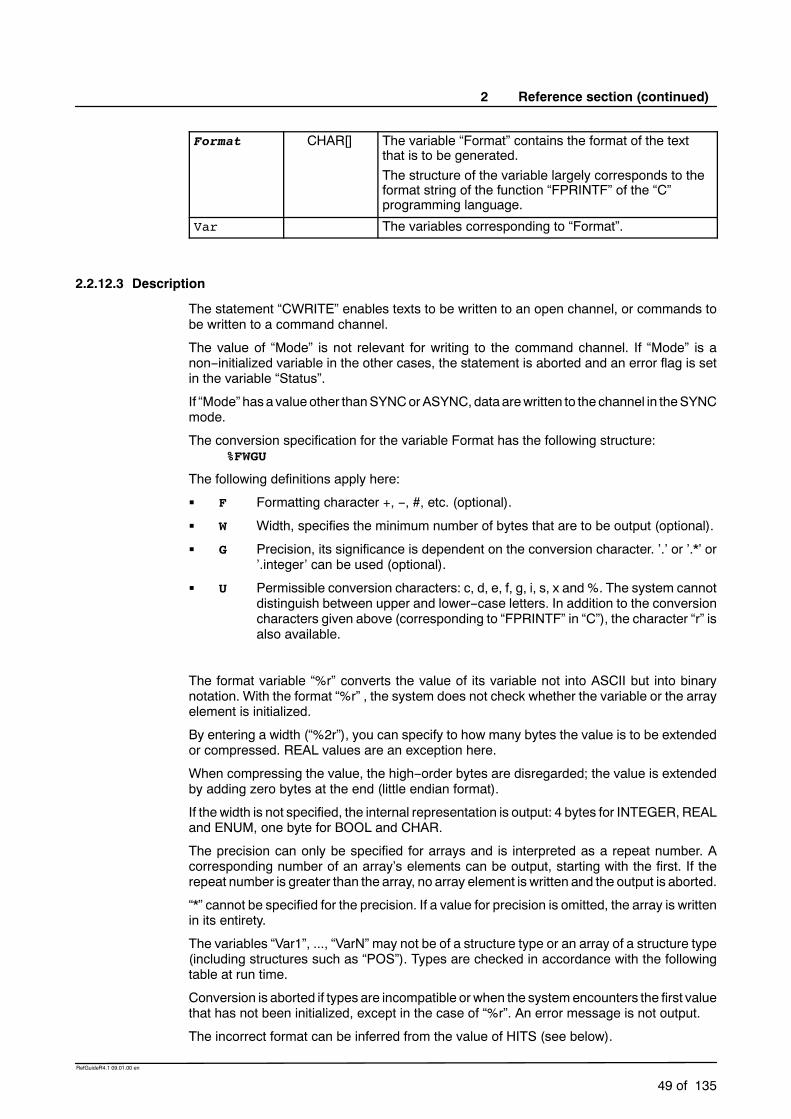
2 Reference section (continued)
49 of 135
RefGuideR4.1 09.01.00 en
Format CHAR[] The variable “Format” contains the format of the textthat is to be generated.The structure of the variable largely corresponds to theformat string of the function “FPRINTF” of the “C”programming language.
Var The variables corresponding to “Format”.
2.2.12.3 Description
The statement “CWRITE” enables texts to be written to an open channel, or commands tobe written to a command channel.
The value of “Mode” is not relevant for writing to the command channel. If “Mode” is anon--initialized variable in the other cases, the statement is aborted and an error flag is setin the variable “Status”.
If “Mode” hasa value other thanSYNCorASYNC, data arewritten to the channel in theSYNCmode.
The conversion specification for the variable Format has the following structure:%FWGU
The following definitions apply here:
G F Formatting character +, --, #, etc. (optional).
G W Width, specifies the minimum number of bytes that are to be output (optional).
G G Precision, its significance is dependent on the conversion character. ’.’ or ’.*’ or’.integer’ can be used (optional).
G U Permissible conversion characters: c, d, e, f, g, i, s, x and %. The system cannotdistinguish between upper and lower--case letters. In addition to the conversioncharacters given above (corresponding to “FPRINTF” in “C”), the character “r” isalso available.
The format variable “%r” converts the value of its variable not into ASCII but into binarynotation. With the format “%r” , the system does not check whether the variable or the arrayelement is initialized.
By entering a width (“%2r”), you can specify to how many bytes the value is to be extendedor compressed. REAL values are an exception here.
When compressing the value, the high--order bytes are disregarded; the value is extendedby adding zero bytes at the end (little endian format).
If the width is not specified, the internal representation is output: 4 bytes for INTEGER, REALand ENUM, one byte for BOOL and CHAR.
The precision can only be specified for arrays and is interpreted as a repeat number. Acorresponding number of an array’s elements can be output, starting with the first. If therepeat number is greater than the array, no array element is written and the output is aborted.
“*” cannot be specified for the precision. If a value for precision is omitted, the array is writtenin its entirety.
The variables “Var1”, ..., “VarN” may not be of a structure type or an array of a structure type(including structures such as “POS”). Types are checked in accordance with the followingtable at run time.
Conversion is aborted if types are incompatible or when the systemencounters the first valuethat has not been initialized, except in the case of “%r”. An error message is not output.
The incorrect format can be inferred from the value of HITS (see below).

Reference Guide
50 of 135
RefGuideR4.1 09.01.00 en
Boolean values are output as 0 or 1, ENUM values as numbers.
Format
Variable
%d
%i
%x
%f
%e
%g
%c %s %1r %1.
hWDHi
r
%2r %2.
hWDHi
r
%4r %4.
hWDHi
r
%r %.
hWDHi
r
(Signal)INT
X X -- -- X -- X -- X -- X --
INT array -- -- -- -- -- X -- X -- X X X
REAL -- X -- -- -- -- -- -- X -- X --
REALarray -- -- -- -- -- -- -- -- -- X X X
(Signal)BOOL X -- -- -- X -- X -- X -- X --
BOOLarray -- -- -- -- -- X -- X -- X X X
ENUM X -- -- -- X -- X -- X -- X --
ENUMarray -- -- -- -- -- X -- X -- X X X
CHAR X -- X -- X -- -- -- -- -- X --
CHARarray -- -- -- X -- X -- -- -- -- X X
The “CWRITE” statement, which can be used in programs at the control or robot levels,triggers an advance run stop.
Particularly time--intensive input and output operations can have a considerable effect onprogram execution.The following applies to all statements: A statement always waits until it is completelyfinished and then returns to the program. This is particularly important for the absoluteCWRITE statements for command channels.Regardless of this, these statements can be interrupted by interrupt routines. Any attemptsto access channels there can themselves be interrupted again only by other interruptsubprograms.Commands which can return segmented or several feedback signals are rejected by thecommand channel.The complete definition of the status and mode information for channel instructions can befound in the “CHANNEL” declaration.

2 Reference section (continued)
51 of 135
RefGuideR4.1 09.01.00 en
2.2.12.4 Example
Several examples of the “CWRITE” statement are given below.
Conversion of the value into decimal and hexadecimal format
Conversion of the value of “I” into decimal and hexadecimal ASCII format:
INT II=123
%D,I ;transmission data 3 bytes: 123
%X,I ;transmission data 2 bytes: 7B
Conversion of the value of “I” into binary notation
INT II=123%R,I ;transmission data 1 byte:{ (Hex. 7B)
I=123456%R,I ;transmission data 3 bytes:@â�(Hex.40E201)
Writing of the first 5 array names of R[ ]
Writing of the values of the first 5 array names of “R[ ]”. Random values are generated forarray elements that have not been initialized.
REAL R[10]
%.5R,R[] ; transmission data 20 bytes in binary notation
Output of values of all array elements
The following statement is used to output the values of all array elements:
REAL R[10]
%R,R[]
Output of certain array elements
Output of the array elements of “S”, ending with the first non--initialized element:
CHAR S[100]
%S,S[]
Writing of the first 50 array elements of S
Writing of the first 50 array elements of “S”, disregarding the initialization information:
CHAR S[100]
%.50R,S[]
Conversion of the internal value of the ENUM variable into ASCII
Conversion of the internal value of the “ENUM” variable into ASCII. The correspondingnumber is output.
DECL ENUM_TYP E
%D,E

Reference Guide
52 of 135
RefGuideR4.1 09.01.00 en
Writing of two real values (defined length) with name
REAL W1,W2
W1=3.97
W2=-27.3
CWRITE(..,..,..,”Value1=%+#07.3F Value2=+#06.2F”,W1.W2);transmission data: Value1=+03.970 Value2=-27.30
A complete example of a program can be found in the chapter “CHANNEL”.

2 Reference section (continued)
53 of 135
RefGuideR4.1 09.01.00 en
DECL
2.2.13 DECL
2.2.13.1 Brief information
Declaration of variables and constants in programs and data lists.
2.2.13.2 Syntax
Declaration of variables in programs:
�DECL Data_Type Variable_Name1 �, ...,Variable_NameN
Declaration of arrays in programs:
�DECL Data_Type Array_Name1 [Size1 �, ...,Size3 ] �, ..., Array_NameN [SizeN1 �,...,SizeN3 ]
Declaration of variables in data lists:
�DECL �GLOBAL Data_Type Variable_Name1 �, ...,Variable_NameN
or with simultaneous value assignment:
�DECL �GLOBAL Data_Type Variable_Name = Value
Declaration of arrays in data lists:
�DECL �GLOBAL Data_Type Array_Name [Size1 �,...,Size3 ] �, ..., Array_NameN [SizeN1 �,...,SizeN3 ]
Declaration and initialization of constants in data lists:
DECL �GLOBAL CONST Data_Type Constant_Name = Value
Declaration and initialization of constant arrays in data lists:
DECL �GLOBAL CONST Data_Type Array_Name [Size1 �,...,Size3 ]
Array_Name[1 �, 1, 1 ] = Value1...Array_Name[Size1 �, Size2, Size3 ] = ValueN
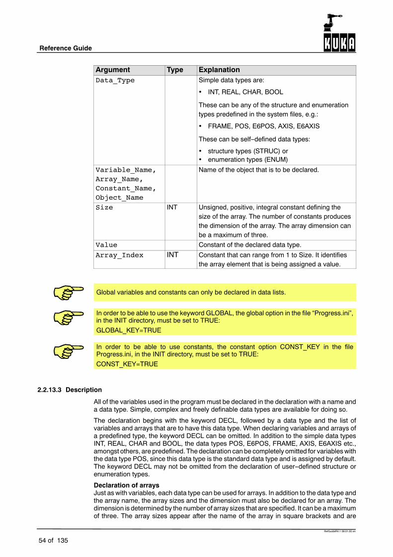
Reference Guide
54 of 135
RefGuideR4.1 09.01.00 en
Argument Type ExplanationData_Type Simple data types are:
INT, REAL, CHAR, BOOL
These can be any of the structure and enumerationtypes predefined in the system files, e.g.:
FRAME, POS, E6POS, AXIS, E6AXIS
These can be self--defined data types:
structure types (STRUC) or enumeration types (ENUM)
Variable_Name,Array_Name,Constant_Name,Object_Name
Name of the object that is to be declared.
Size INT Unsigned, positive, integral constant defining thesize of the array. The number of constants producesthe dimension of the array. The array dimension canbe a maximum of three.
Value Constant of the declared data type.
Array_Index INT Constant that can range from 1 to Size. It identifiesthe array element that is being assigned a value.
Global variables and constants can only be declared in data lists.
In order to be able to use the keyword GLOBAL, the global option in the file “Progress.ini”,in the INIT directory, must be set to TRUE:GLOBAL_KEY=TRUE
In order to be able to use constants, the constant option CONST_KEY in the fileProgress.ini, in the INIT directory, must be set to TRUE:CONST_KEY=TRUE
2.2.13.3 Description
All of the variables used in the programmust be declared in the declaration with a name anda data type. Simple, complex and freely definable data types are available for doing so.
The declaration begins with the keyword DECL, followed by a data type and the list ofvariables and arrays that are to have this data type. When declaring variables and arrays ofa predefined type, the keyword DECL can be omitted. In addition to the simple data typesINT, REAL, CHAR and BOOL, the data types POS, E6POS, FRAME, AXIS, E6AXIS etc.,amongst others, are predefined. The declaration can be completely omitted for variableswiththe data type POS, since this data type is the standard data type and is assigned by default.The keyword DECL may not be omitted from the declaration of user--defined structure orenumeration types.
Declaration of arraysJust as with variables, each data type can be used for arrays. In addition to the data type andthe array name, the array sizes and the dimension must also be declared for an array. Thedimension is determined by the number of array sizes that are specified. It can be amaximumof three. The array sizes appear after the name of the array in square brackets and are

2 Reference section (continued)
55 of 135
RefGuideR4.1 09.01.00 en
separated by commas. Each array size is an unsigned, integral constant. It must be equalto or greater than 1.
If an array is transferred as a formal parameter in a subprogram or function call, it must bedeclared in the definition of this subprogram or function, just like a variable. The array sizesmust be omitted in this declaration but not the square brackets and the commas whichdetermine the array dimension.When calling the subprogram or function, the array sizes aredetermined by the associated current parameters that are transferred.
Declaration of variables with a default settingVariables can be declared in data lists and assigned an initial value as a default at the sametime. A declaration statement containing a default setting cannot be used in the declarationsection of programs and functions.
In the case of variables with simple data types, the initial value is to be specified as a simpleconstant. With structure variables, the initial value is an aggregate.
The declaration statement for assigning a default setting to variables begins, just like with thesimple declaration, with the keyword DECL, a data type and the name of the variable that isto be assigned a default setting.
An “=” sign and the initial value given in the form of a constant follow the variable name.Whendeclaring a default setting, you cannot list several variables in a declaration statement. Aseparate declaration statement is required for each variable that is to be assigned a defaultsetting. The keyword DECL may also be omitted when assigning a default setting.
The data type of the constant to the right of the “=” sign must be compatible with the explicitlyspecified data type on the left--hand side but does not have to be identical to it. If the datatypes are compatible, the system automatically matches them, as in the case of a valueassignment.
Declaration of arrays with a default settingAdeclaration statement containing a default setting cannot be used in the declaration sectionof programs and functions. Nor can a single line in a data list contain both declarations andinitializations.
In the case of an array with a simple data type, the initial values are to be specified as simpleconstants. In the case of arrays with a structure type, the initial value for each array elementis an aggregate.
When declaring default settings for arrays, a separate statement must be written for eacharray element.
The declaration for assigning a default setting to an array consists of at least two blocks.
G The first block contains a normal array declaration with the declaration DECL.
G The second block contains the specification of an array element, followed by an “=” signand the initial value for this element.
G Further blocks of this type inwhich default settings are assigned to other array elementsmay follow.
When assigning a default setting to more than one element of an array, the elements mustbe specified in ascending sequence of the array index. The right--hand array index variesfastest.
The data type of the constant to the right of the “=” sign must be compatible with the explicitlydeclared data type of the array but does not have to be identical to it. If the data types arecompatible, the system automatically matches them, as in the case of a value assignment.
Assigning character strings as defaultsIf you want to assign the same character string to all of the elements of an array of typeCharacter as a default setting, you do not have to assign it to each array element individually.The right--hand array index is omitted (i.e. no index is written for a one--dimensional array)and a character string constant is thus assigned as a default setting to an entire line.

Reference Guide
56 of 135
RefGuideR4.1 09.01.00 en
Declarations of variables of the data type “freely definable structure type” or “freelydefinable enumeration type”
The keyword DECL must be programmed here if the following data type name is not apredefined system data type. The data type definitions STRUC and ENUM must alwaysappear before the DECL declaration for all variables of this type.
2.2.13.4 Example:
Declaration without initialization.DECL POS P1; The keyword DECL can also be omittedINT A1,A2REAL VEL[7],ACC[7],BDECL S_PAR_TYPE S_PAR[3]
Declaration of arrays with initialization (only in data lists).INT A[7] ; Array for 7 integer valuesA[1]=27 ; The first array element is assigned the value 27A[2]=313A[6]=11CHAR TEXT1[80]TEXT1[]=”Message Text”CHAR TEXT2[2,80]TEXT2[1,]=”First Message Text”TEXT2[2,]=”Second Message Text”
Declaration of variables with initialization (only in data lists).FRAME F1={X 123.4, Y -56.7, Z 89.56}
STRUC, ENUM, DEFDAT

2 Reference section (continued)
57 of 135
RefGuideR4.1 09.01.00 en
DEF ... END
2.2.14 DEF ... END
2.2.14.1 Brief information
Declaration of programs and subprograms.
2.2.14.2 Syntax
�GLOBAL DEF Program_Name(�Parameter_List )�DECL Data_Type Parameter_Name1...DECL Data_Type Parameter_NameZ�further declarations�StatementsEND
Parameter_List = Parameter_Name1� , ..., Parameter_NameI : IN | �OUT � , ...,� Parameter_NameN� , ..., Parameter_NameZ : IN | �OUT
Argument Type ExplanationProgram_Name The name of the program that is to be defined is
entered here. It is an object name and may not bemore than 24 characters long in the case of globalfunctions. The length is restricted by the controller’sdirectory system.
Parameter_List
The parameter list contains the followingspecifications:
Parameter names. In the case of output parameters of type Array
(input parameters cannot be arrays), the arraydimension is added to the name of the arrayusing the following notation:
[] One--dimensional array[,] Two--dimensional array[,,] Three--dimensional array
The transfer mode of the respective parameter:
:IN Input parameter (call by value)
:OUT Output parameter (call by reference)(default value)

Reference Guide
58 of 135
RefGuideR4.1 09.01.00 en
Declaration Only declarations may appear in the declarationsection. Program statements cannot be used here.The border between the declaration section and thestatement section is defined by the first statement.
Statements Only statements may appear in the statementsection. Declarations cannot be used here. You canexit a local subprogram using a RETURN statement.Without a RETURN statement, the END statement isthe last statement to be executed.
2.2.14.3 Description
By default, the first program in an SRC file has the same name as the SRC file and isrecognized globally, even without using the keyword GLOBAL.
When a program is called, there are two kinds of parameter transfer: transfer with an inputparameter and transfer with an output parameter.
Input parameter (keyword IN)Only the value of the variable is transferred here. This direct parameter transfer works likethe assignment of a default setting to the variable in the subprogram. The value that iscurrently transferred can be a constant, a variable, a function call or a simple or complexexpression.
A value cannot be returned to the calling module in the case of an IN parameter (call byvalue). It is only used for transferring a value to the subprogram.
If the data types of the current and formal IN parameters are not identical but are compatible,the system automatically converts the type of the value that has been transferred. Arrayscannot be transferred as an input parameter (IN).
Output parameter (keyword OUT)A variable name is transferred here (call by reference). The variable must have a value atthe time of the subprogram call. This value can be used in the subprogram that is called.
A parameter of type OUT can be assigned a (new) value in the subprogram that is called.For this reason, the data types of the current and formal parameters must be identical in thecase of the transfer mode OUT.
Transfer as an output parameter is the default setting, i.e. OUT does not have to be specified.
END statementThe END statement is always the last block of a global or local subprogram. The last blockof a subprogram that can be executed is either the RETURN statement or, if this is missing,the END statement.

2 Reference section (continued)
59 of 135
RefGuideR4.1 09.01.00 en
2.2.14.4 Example:
Declaration of a program without formal parameters.DEF PROG()...END
Declaration of a subprogram with the formal parameters Current and Voltage. Due tothe default setting, they are output parameters.DEF WELD(CURRENT,VOLTAGE)...END
Declaration of a subprogram with the formal parameters Current and Voltage as inputparameters and RESULT as an output parameter.DEF WELD(CURRENT:IN,VOLTAGE:IN,RESULT:OUT)...END
In the subprogram CALCULATE, some variables undergo arithmetic operations. Afterthe subprogram has been called, the variables A and B in the main program have thefollowing values: A=11, B=2.DEF PROG()INT A,BA=1B=2CALCULATE(A,B)...END
DEF CALCULATE(X1:OUT,X2:IN)INT X1,X2X1=X1+10X2=X2+10END
END, DEFFCT, RETURN

Reference Guide
60 of 135
RefGuideR4.1 09.01.00 en
DEFDAT ... ENDDAT
2.2.15 DEFDAT ... ENDDAT
2.2.15.1 Brief information
Declaration of data lists.
2.2.15.2 Syntax
DEFDAT Data_List_Name �PUBLIC�DeclarationsENDDAT
Argument Type ExplanationData_List_Name
The name of the data list that is to be defined isentered here. It is an object name and can have amaximum length of 24 characters. The length isrestricted by the controller’s directory system.
If the name of the data list is identical to that of amodule, the data list is then assigned to this module,as a result of which the declarations of the data listalso apply in the module of the same name. Amodule and the data list assigned to it form amodule package.
PUBLIC By adding this keyword, other modules and data listscan also access this data list, and the variables, etc.,that are defined here can be used in other modulepackages. They must be declared using the keywordGLOBAL.
Declaration External declarations for subprograms andfunction modules that are used in the module.
Import declarations for imported variables. Declarations for variables. Declarations for signal and channel names. Declarations for structure and enumeration types. The variable declarations in the declaration
section of the data list may contain defaultsettings.
2.2.15.3 Description
In addition to the predefined data lists, you can define further data lists yourself. Data listsare used for preparing program--specific and higher--level declarations. Variable values thatcan be saved (=default settings) can be declared in data lists. In particular, the data lists cancontain taught positions. A data list can also exist as an independent object. In this case,there is no module of the same name.
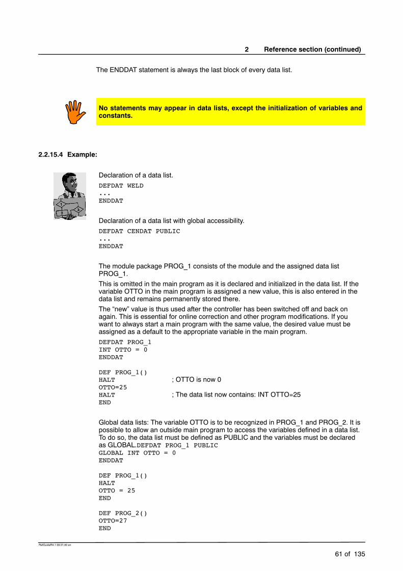
2 Reference section (continued)
61 of 135
RefGuideR4.1 09.01.00 en
The ENDDAT statement is always the last block of every data list.
No statements may appear in data lists, except the initialization of variables andconstants.
2.2.15.4 Example:
Declaration of a data list.DEFDAT WELD...ENDDAT
Declaration of a data list with global accessibility.DEFDAT CENDAT PUBLIC...ENDDAT
The module package PROG_1 consists of the module and the assigned data listPROG_1.This is omitted in the main program as it is declared and initialized in the data list. If thevariable OTTO in the main program is assigned a new value, this is also entered in thedata list and remains permanently stored there.The “new” value is thus used after the controller has been switched off and back onagain. This is essential for online correction and other program modifications. If youwant to always start a main program with the same value, the desired value must beassigned as a default to the appropriate variable in the main program.DEFDAT PROG_1INT OTTO = 0ENDDAT
DEF PROG_1()HALT ; OTTO is now 0OTTO=25HALT ; The data list now contains: INT OTTO=25END
Global data lists: The variable OTTO is to be recognized in PROG_1 and PROG_2. It ispossible to allow an outside main program to access the variables defined in a data list.To do so, the data list must be defined as PUBLIC and the variables must be declaredas GLOBAL.DEFDAT PROG_1 PUBLICGLOBAL INT OTTO = 0ENDDAT
DEF PROG_1()HALTOTTO = 25END
DEF PROG_2()OTTO=27END

Reference Guide
62 of 135
RefGuideR4.1 09.01.00 en
IMPORT

2 Reference section (continued)
63 of 135
RefGuideR4.1 09.01.00 en
DEFFCT ... ENDFCT
2.2.16 DEFFCT ... ENDFCT
2.2.16.1 Brief information
Declaration of functions.
2.2.16.2 Syntax
�GLOBAL DEFFCT Data_Type Function_Name (�Parameter_List )�DECL Data_Type Parameter_Name1...DECL Data_Type Parameter_NameZ
�further declarations�StatementsENDFCT
Parameter_List = Parameter_Name1� , ..., Parameter_NameI : IN | �OUT � , ...,� Parameter_NameN� , ..., Parameter_NameZ : IN | �OUT
Argument Type ExplanationGLOBAL The keyword GLOBAL makes the function available
for all loaded KRL programs.Data_Type Data type of the function.
Function_Name
Name of the function that is to be defined. It is anobject name and may not be more than 24characters long. The length is restricted by thecontroller’s directory system.
Parameter_List
The parameter list contains the followingspecifications:
The parameter names. In the case of output parameters of type Array
(input parameters cannot be arrays), the arraydimension is added to the name of the arrayusing the following notation:
[] One--dimensional array[,] Two--dimensional array[,,] Three--dimensional array
The transfer mode of the respective parameter:
:IN Input parameter (call by value)
:OUT Output parameter (call by reference)(default value)

Reference Guide
64 of 135
RefGuideR4.1 09.01.00 en
Declarations Only declarations may appear in the declarationsection. The border between the declaration sectionand the statement section is defined by the firststatement.
Statements Only statements may appear in the statementsection. The return value of the function istransferred using the RETURN statement.
2.2.16.3 Description
A function sends a return value to the calling module. A function call is an expression andthe function can thus be assigned to a variable or used by other arithmetic statements.Whencalling a function, there are two kinds of parameter transfer: transfer with an input parameterand transfer with an output parameter.
Input parameter
A value is transferred. The direct parameter transfer works like the assignment of a defaultsetting to the variable in the function.
The value that is currently transferred can be a constant, a variable, a function call or a simpleor complex expression. A value cannot be returned to the calling module in the case of anIN parameter (call by value). It is only used for transferring a value to the subprogram orfunction.
If the data types of the current and formal IN parameters are not identical but are compatible,the system automatically converts the type of the value that has been transferred. Arrayscannot be transferred as an input parameter (IN).
Output parameter
A variable name is transferred here (call by reference). The variable can have a value at thetime of the subprogram call. This value can be used in the subprogram that is called.
A parameter of type OUT can be assigned a (new) value in the function that is called. Thisvalue is then returned to the callingmodule, which canmake further use of it. For this reason,the data types of the current and formal parameters must be identical in the case of thetransfer mode OUT.
Transfer as an output parameter is the default setting, i.e. OUT does not have to be specified.
ENDFCT statement
The ENDFCT statement is always the last block of a global or local function. The last blockof a function that can be executed is always the RETURN statement. If the interpreterencounters an ENDFCT statement whilst executing a function, a runtime error occurs.

2 Reference section (continued)
65 of 135
RefGuideR4.1 09.01.00 en
2.2.16.4 Example
Declaration of a function of data type INT with the name FCT1 and the transferredparameters P1 and P2.DEFFCT INT FCT1(P1,P2)...ENDFCT
Declaration of a function of data type BOOL with the name WELD and the inputparameters CURRENT and VOLTAGE.DEFFCT BOOL WELD(CURRENT:IN,VOLTAGE:IN)...ENDFCT
In a function, the difference between two variables is to be calculated and transferred tothe main program.DEF PROG_1()EXTFCT INT DELTA(INT:OUT,INT:OUT)INT A,B,CA=1B=25C=DELTA(A,B)END
DEFFCT INT DELTA(X1:OUT,X2:OUT)INT X1,X2,X3X3=X2-X1RETURN(X3)ENDFCT
DEF, RETURN

Reference Guide
66 of 135
RefGuideR4.1 09.01.00 en
DIGIN
2.2.17 DIGIN
2.2.17.1 Brief information
Cyclic reading in of digital inputs.
2.2.17.2 Syntax
Reading a digital input:
DIGIN ON Signal_Value = Factor * $DIGINX ����� Offset
Termination of the read operation:
DIGIN OFF $DIGINX
Argument Type ExplanationSignal_Value Real The result of the operation is stored in Signal_Value.
It can be a variable or a signal name.Factor Real The factor can be a constant, variable or signal name.
$DIGINX $DIGINX designates a predefined digital signalname: $DIGIN1 to $DIGIN6.
Offset Real Offset can be a constant, variable or signal name.
All of the variables used in the DIGIN statement must be declared in data lists.
Accessing the digital inputs triggers an advance run stop. Array indices are only evaluatedonce in the DIGIN ON statement. The expression that is produced after the array indiceshave been replaced by numeric values is cyclically evaluated. Digital inputs cannot be usedin the INTERRUPT statement.
2.2.17.3 Description
The controller provides six digital interfaces which can be read via the predefined signalvariables $DIGIN1 to $DIGIN6. Each of the digital inputs can have a length of 32 bits and anassociated strobe output. The controller can interpret these inputs with or without a sign. Thedigital inputs are configured in the file “$MACHINE.DAT”.
The digital inputs can be read over a period of time using DIGIN or can be assigned to avariable of data type REAL once by means of the operator “=”. Two DIGIN ON statementscan be used at the same time. Two DIGIN ON statements can read the same digital input.It is possible to logically combine digital inputs with other operators and to assign them to asignal value by using the optional arithmetic of the DIGIN statement. A DIGIN ON statementcan also access analog input signals (see example).
The cyclic read--in of the digital inputs is deactivated using the DIGIN OFF statementfollowed by the signal name.

2 Reference section (continued)
67 of 135
RefGuideR4.1 09.01.00 en
2.2.17.4 Examples
The digital input $DIGIN1 is assigned to the binary input signals $IN[1020] to $IN[1026].The analog input $ANIN[1] is assigned the symbolic name FACTOR. The system variable$TECHIN[1] is assigned the result of the product of the analog input value and the digitalinput, increased by the value of the variable OFFSET. The DIGIN OFF instructiondeactivates the cyclic read--in of the digital inputs.SIGNAL $DIGIN1 $IN[1020] TO $IN[1026]SIGNAL FACTOR $ANIN[1]DIGIN ON $TECHIN[1] = FACTOR * $DIGIN1 + OFFSET...DIGIN OFF $DIGIN1
SIGNAL, ANIN, ANOUT

Reference Guide
68 of 135
RefGuideR4.1 09.01.00 en
ENUM
2.2.18 ENUM
2.2.18.1 Brief information
Declaration of enumeration data types.
2.2.18.2 Syntax
�GLOBAL ENUM Enumeration_Type_Name Enumeration_Constant1�,..., Enumeration_ConstantN
Argument Type ExplanationEnumeration_Type_Name
Name of the new enumeration data type.
Enumeration_Constant
The enumeration constants are the values that avariable of the enumeration data type can take. Thename of each constant must be unambiguous withinthe data type.
The keyword GLOBAL, in the context of declaring Enum data types, may only be used indata lists.
2.2.18.3 Description
The enumeration type is a data type made up of a finite number of integer constants. Theenumeration constants represent the discrete values that an enumeration variable can take.Variables with an enumeration type do not follow a continuous scale of values, but can onlytake the constants that are listed in thedefinition as values. The constants are freely definablenames and can be defined by the user.
The enumeration type definition may appear in the declaration section of modules or in datalists. Global ENUM declarations are only allowed in data lists.
Symbolic designation of enumeration constants
You are able to use short or full symbolic names.
If using short symbolic names, a “#” character is inserted before the nameof the enumerationconstant, e.g. #monday.
If using a full symbolic name, an enumeration constant is identified by the name of theenumeration type followed by a “#” character and the name of the enumeration constant, e.g.WEEK_TYPE#MONDAY. There are two instances where the full symbolic name ofenumeration constants must be given:
1. If the enumeration constant is used as a current parameter in a subprogramor functioncall in an individual command outside the module.
2. If the enumeration constant appears on the left--hand side of a comparison.
The names of enumeration types should end in _TYPE so as to distinguish variable namesfrom enumeration types.

2 Reference section (continued)
69 of 135
RefGuideR4.1 09.01.00 en
2.2.18.4 Example
Declaration of an enumeration data type with the name STATE_TYPE and theconstants S_START, S_STOP and S_WAIT.ENUM STATE_TYPE S_STOP, S_START, S_WAIT
An enumeration data type with the name SWITCH_TYPE and the constants ON andOFF is declared in the following program. These are addressed in the program usingtheir short symbolic names.DEF PROG()ENUM SWITCH_TYPE ON, OFFDECL SWITCH_TYPE ADHESIVEIF A>10 THEN
ADHESIVE=#ONELSE
ADHESIVE=#OFFENDIFEND
DECL, STRUC
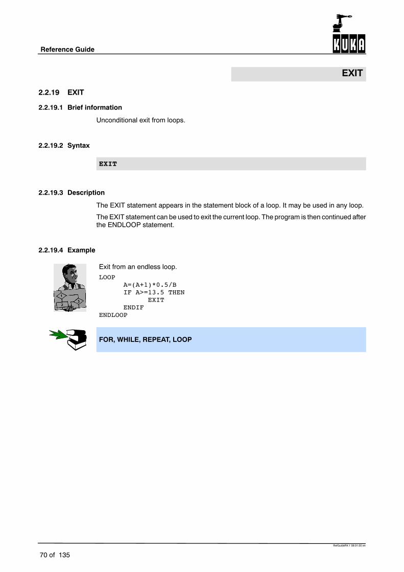
Reference Guide
70 of 135
RefGuideR4.1 09.01.00 en
EXIT
2.2.19 EXIT
2.2.19.1 Brief information
Unconditional exit from loops.
2.2.19.2 Syntax
EXIT
2.2.19.3 Description
The EXIT statement appears in the statement block of a loop. It may be used in any loop.
The EXIT statement can be used to exit the current loop. The program is then continued afterthe ENDLOOP statement.
2.2.19.4 Example
Exit from an endless loop.LOOP
A=(A+1)*0.5/BIF A>=13.5 THEN
EXITENDIF
ENDLOOP
FOR, WHILE, REPEAT, LOOP

2 Reference section (continued)
71 of 135
RefGuideR4.1 09.01.00 en
EXT
2.2.20 EXT
2.2.20.1 Brief information
Declaration of external subprograms.
2.2.20.2 Syntax
EXT Program_Source(�Parameter_List )
Parameter_List = Data_Type1� , ..., Data_TypeI : IN | �OUT � , ...,� Data_TypeN� , ...,Data_TypeZ : IN | �OUT
Argument Type ExplanationProgram_Source
Identifies the path and the name of the subprogramused.
Parameter_List
The parameter list contains the followingspecifications:
The data types of all of the parameters of theexternal subprogram in the defined sequence.
In the case of array parameters, the arraydimension using the following notation:
[] One--dimensional array[,] Two--dimensional array[,,] Three--dimensional array
The transfer mode of the respective parameter:
:IN Input parameter (call by value):OUT Output parameter (call by
reference) (default value)
The sequence of the parameter list must beobserved. The individual parameters are separatedfrom one another by commas.
EXT declarations cannot be used in subprograms.
2.2.20.3 Description
The EXT declaration is used to identify external subprograms to the program in which theyare called. Only the main program can be used (program name is the same as the name ofthe SRC file), not other subprograms in the same file. Other subprograms in an SRC file canbe identified generally using the keyword GLOBAL.
The EXT declaration must be used to make both the name and path of the subprogram thatis to be called and the parameters that are used known to the compiler. By specifying aparameter list, the required storage space is also clearly defined.
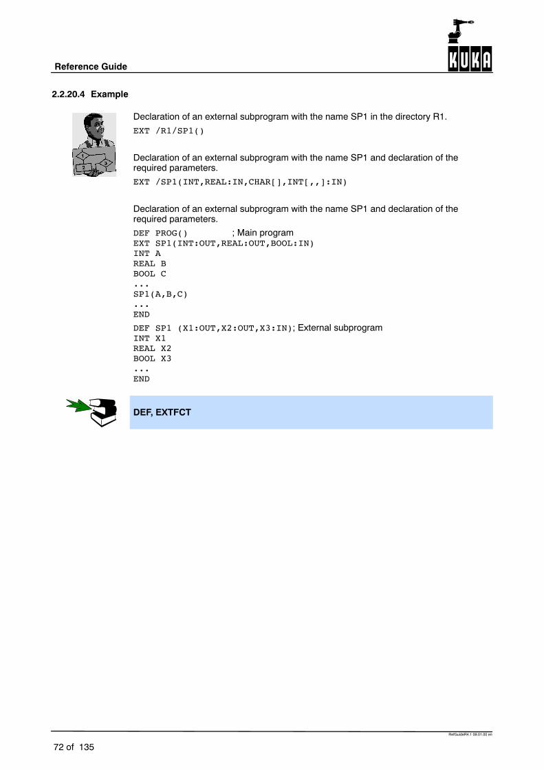
Reference Guide
72 of 135
RefGuideR4.1 09.01.00 en
2.2.20.4 Example
Declaration of an external subprogram with the name SP1 in the directory R1.EXT /R1/SP1()
Declaration of an external subprogram with the name SP1 and declaration of therequired parameters.EXT /SP1(INT,REAL:IN,CHAR[],INT[,,]:IN)
Declaration of an external subprogram with the name SP1 and declaration of therequired parameters.DEF PROG() ; Main programEXT SP1(INT:OUT,REAL:OUT,BOOL:IN)INT AREAL BBOOL C...SP1(A,B,C)...END
DEF SP1 (X1:OUT,X2:OUT,X3:IN); External subprogramINT X1REAL X2BOOL X3...END
DEF, EXTFCT

2 Reference section (continued)
73 of 135
RefGuideR4.1 09.01.00 en
EXTFCT
2.2.21 EXTFCT
2.2.21.1 Brief information
Declaration of external local functions.
2.2.21.2 Syntax
EXTFCT Data_Type Program_Source(�Parameter_List )
Parameter_List = Data_Type1� , ..., Data_TypeI : IN | �OUT � , ...,� Data_TypeN� , ...,Data_TypeZ : IN | �OUT
Argument Type ExplanationData_Type The data type must correspond to the function
declaration.Program_Source
Identifies the path and the name of the function used.
Parameter_List
The parameter list contains the followingspecifications:
The data types of all of the parameters of theexternal function in the defined sequence.
In the case of array parameters, the arraydimension using the following notation:
[] One--dimensional array[,] Two--dimensional array[,,] Three--dimensional array
The transfer mode of the respective parameter:
:IN Input parameter (call by value):OUT Output parameter (call by
reference) (default value)
The sequence of the parameter list must beobserved. The individual parameters are separatedfrom one another by commas.
EXTFCT declarations cannot be used in subprograms.
2.2.21.3 Description
The EXTFCT declaration is used to identify external functions to the program in which theyare called. Only the main program can be used (function name is the same as the name ofthe SRC file), not other functions in the same file. Other functions in an SRC file can beidentified generally using the keyword GLOBAL.

Reference Guide
74 of 135
RefGuideR4.1 09.01.00 en
The EXTFCT declaration must be used to make both the name and path of the externalfunction that is to be called and the parameters used known to the compiler. By specifyinga parameter list, the required storage space is also clearly defined.
2.2.21.4 Example
Declaration of an external function with the name FCT1 in the directory R1.EXTFCT /R1/FCT1()
DEF PROG()
; Main programEXTFCT INT DELTA(INT:OUT,INT:IN)INT A,B,C...A=5B=20C=DELTA(A,B)
; Function call...END
Declaration of an external function with the name FCT1 and the transfer parameters.EXTFCT /FCT1(INT,REAL:IN,CHAR[],INT[,,]:IN)
Declaration of an external function with the name FCT1 and the transfer parameters.EXTFCT FCT1(INT:OUT,REAL:OUT,BOOL:IN)
In a function, the difference between 2 variables is to be calculated and transferred tothe main program. The values of the variables after the function has been called are:A=15, B=20, C=15.
DEF PROG()
; Main programEXTFCT INT DELTA(INT:OUT,INT:IN)INT A,B,C...A=5B=20C=DELTA(A,B)
; Function call...END
DEFFCT INT DELTA(X1:OUT,X2:IN); External functionINT X1,X2,X3X1=X2-X1X3=X1RETURN(X3)ENDFCT

2 Reference section (continued)
75 of 135
RefGuideR4.1 09.01.00 en
DEFFCT, EXT

Reference Guide
76 of 135
RefGuideR4.1 09.01.00 en
FOR ... TO ... ENDFOR
2.2.22 FOR ... TO ... ENDFOR
2.2.22.1 Brief information
Counting loop.
2.2.22.2 Syntax
FOR Counter = Start TO End �STEP Increment�StatementsENDFOR
Argument Type ExplanationCounter INT An integer variable used as a loop counter.
Start INT Arithmetic expression specifying the initial value forthe counter.
End INT Arithmetic expression specifying the final value forthe counter.
Increment INT Arithmetic expression of the amount by which thecounter is incremented with each execution of theloop:
Increment may be negative Increment may not be zero Increment may not be a variable
If no increment is specified, the default value 1 isused.
2.2.22.3 Description
A specified number of runs can be very clearly programmed using the FOR loop. The loopruns are counted with the aid of the counter.
The execution condition for FOR is as follows:
with a positive increment: if the counter is greater than the final value, then the loopis ended.
with a negative increment: if the counter is less than the final value, then the loop isended.
The execution condition is checked before each loop run. In extreme cases, the FOR loopis not executed at all.
An expression of type Integer must be given for both the initial and final values of the counter.The expressions are evaluated once at the start of the loop. The timer is preset to the initialvalue and is incremented or decremented after each loop run.
The increment may not be zero. If no increment is specified, it has the default value 1.Negative values can also be used for the increment.
The value of the counter can be used in the statements inside and outside of the loop.Withinthe loop, it serves, for example, as an up--to--date index for the processing of arrays. Afterexiting the loop, the counter retains its most recent value.
There must be an ENDFOR statement for every FOR statement. After completion of the lastloop execution, the program is resumed with the first instruction after ENDFOR. The loopexecution can be exited prematurely using the EXIT statement.

2 Reference section (continued)
77 of 135
RefGuideR4.1 09.01.00 en
2.2.22.4 Example
FOR loop that increases variable B by 1 in 10 executions.FOR A=1 TO 10
B=B+1ENDFOR
FOR loop that, in steps of two, increments counter A after each run and increasesvariable B by the value of the counter. Should variable B reach the value 10, the loop isprematurely ended.FOR A=1 TO 15 STEP 2
B=B+AIF B==10 THEN
EXITENDIF
ENDFOR
EXIT, SWITCH, REPEAT, WHILE, LOOP

Reference Guide
78 of 135
RefGuideR4.1 09.01.00 en
GOTO
2.2.23 GOTO
2.2.23.1 Brief information
Unconditional jump statement.
2.2.23.2 Syntax
GOTO Marker
Argument Type ExplanationMarker Marker describes the destination of the jump
statement.
2.2.23.3 Description
The unconditional jump statementGOTO is a programexecution instruction. After theGOTOstatement has been processed, the program will resume execution at the point specified bythis statement.
The destination must be in the same subprogram or function as the GOTO statement. It isdefined by the marker followed by a colon.
Jumping to a destination in an IF statement or in a loop from outside, or from one CASEstatement to another CASE statement is not possible.
The program very quickly becomes confusing and unstructured when using GOTO. It isbetter to use the branching statement IF or the selection statement SWITCH instead.
2.2.23.4 Example
Unconditional jump to the program position MARKER_1.GOTO MARKER_1
Unconditional jump from an IF statement to the program position END.IF X>100 THEN
GOTO ENDELSE
X=X+1ENDIFA=A*X...END:END
IF, SWITCH, REPEAT, WHILE, LOOP

2 Reference section (continued)
79 of 135
RefGuideR4.1 09.01.00 en
HALT
2.2.24 HALT
2.2.24.1 Brief information
Interrupts program execution and halts processing.
2.2.24.2 Syntax
HALT
2.2.24.3 Description
The HALT statement stops execution of the program. The last motion instruction to beexecuted will, however, be completed.
Execution of the program can only be resumed using the Start key. The next instruction afterHALT is then executed.
In an interrupt routine, program execution is only stopped after the advance run hasbeen completely executed. In the event of a BRAKE statement, on the other hand,program execution is stopped immediately.
WAIT FOR, WAIT SEC, BRAKE

Reference Guide
80 of 135
RefGuideR4.1 09.01.00 en
IF ... THEN ... ENDIF
2.2.25 IF ... THEN ... ENDIF
2.2.25.1 Brief information
Execution of statements depending on the result of a logical expression.
2.2.25.2 Syntax
IF Condition THENStatements
�ELSEStatements
ENDIF
Argument Type ExplanationCondition BOOL Logical expression which can contain a Boolean
variable, a Boolean function call or a logicaloperation with a Boolean result, e.g. a comparison.
2.2.25.3 Description
The branching statement IF is a program execution instruction. Depending on a condition,either the first statement block (THEN block) or the second statement block (ELSE block) isexecuted. The program is subsequently continued with the statements following ENDIF.
There is no limit on the number of statements contained in the statement blocks. Several IFstatements can be nested in each other.
The keyword ELSE and the second statement block may be omitted. If the condition is notsatisfied, the program is then continued at the position immediately after ENDIF.
There must be an ENDIF for each IF.
2.2.25.4 Example
IF loop without a second statement block.IF A==17 THEN
B=1
ENDIF
IF loop with a second statement block.IF $IN[1] THEN
$OUT[17]=TRUEELSE
$OUT[17]=FALSEENDIF

2 Reference section (continued)
81 of 135
RefGuideR4.1 09.01.00 en
IMPORT ... IS ... .. ...
2.2.26 IMPORT ... IS ... .. ...
2.2.26.1 Brief information
Import of data from data lists.
2.2.26.2 Syntax
IMPORT Data_Type Import_Name IS Data_Source..Data_Name
Argument Type ExplanationData_Type The data must be imported with the data type with
which they are declared in the external data list.Import_Name The imported data can be assigned a name different
to the one that they have in the external data list.Data_Source The data source identifies the path and the name of
the data list from which the data are to be imported.Data_Name The data name corresponds to the variable name
assigned to the data in the external data list.
2.2.26.3 Description
The IMPORT statement allows external data lists bearing the attribute “PUBLIC” to beaccessed. The IMPORT statement allows variables, entire arrays or array elements to beimported into your own programs or data lists from an external data list. Each variable thatis to be imported requires its own IMPORT statement. Variables that have already beenimported cannot be accessed using another IMPORT statement. The variables must beimported from the data lists in which they were originally created.
The data must be imported with the same data type with which they are declared in theexternal data list. The system does not check that the correct data types have been selecteduntil the linking operation is carried out.
The data can be given a different name in your own data list or program to the one that theyhave in the external data list.
The directory and the name of the data list are specified by the path. The data namecorresponds to the name used by the variable in the external data list.
The data source and data nameare connected to one another by two periods. No blanksmayappear between the two periods.

Reference Guide
82 of 135
RefGuideR4.1 09.01.00 en
2.2.26.4 Example
Import of the value of the integer variable VALUE from the data list DATA. The variablename VALUE is retained.IMPORT INT VALUE IS /DATA..VALUE
Abbreviated formIMPORT INT VALUE
Import of the POS array POS_EX from the data list R1/POSITION. The variable nameis to be POS 1 in your program.IMPORT POS POS1[] IS /R1/POSITION..POS_EX
DEFDAT

2 Reference section (continued)
83 of 135
RefGuideR4.1 09.01.00 en
INTERRUPT DECL ... WHEN ... DO
2.2.27 INTERRUPT DECL ... WHEN ... DO
2.2.27.1 Brief information
Declaration of an interrupt.
2.2.27.2 Syntax
GLOBAL INTERRUPT DECL Prio WHEN Event DO Subprogram
Argument Type ExplanationGLOBAL The keyword GLOBAL is used for the identification of
interrupts, including at levels above the subprogram inwhich they are declared. If an interrupt has beendeclared in a subprogram, it is also recognized in themain program in which it is called.
Prio INT Arithmetic expression specifying the priority of theinterrupt. Priority levels 1 to 128 are available, but therange 40--80 is reserved for automatic priorityallocation by the system.An interrupt with priority 1 is processed first.
Event BOOL Logical expression defining the interrupt event. Thefollowing are permissible:
A Boolean constant A Boolean variable A signal name A comparison A simple logical operation: NOT, OR, AND or
EXOR
The following cannot be used:
Structure componentsSubprogram Name and parameters of the subprogram (interrupt
routine) that is to be executed when an interruptoccurs.
If the program has reached a HALT statement, interrupts are still detected andexecuted (including motion instructions!). After the instruction has been executed,the program is once again paused at the HALT statement.
The interrupt declaration is an instruction. It must not, therefore, be located in thedeclaration section!
When first declared, an interrupt is deactivated and disabled.
Runtime variables may not be transferred as interrupt routine parameters, apart fromvariables declared in a data list.
Reference Guide
84 of 135
RefGuideR4.1 09.01.00 en
Up to 32 interrupts may be declared at any one time.
2.2.27.3 Description
The interrupt function allows the user to react to an event that does not occur synchronouslywith program execution, using a program statement. Such events can be an EmergencyStop, error messages, input signals, etc. The possible causes of an interrupt and thesystem’s reaction to each of them are defined using the interrupt declaration. Each interruptis assigned a priority, an event and the interrupt routine that is to be called. 32 interrupts maybe declared at the same time. A declaration may be overwritten by another at any time.
A defined interrupt triggers a reaction if all four of the following conditions are satisfied:
1. The interrupt must be activated (INTERRUPT ON).2. The interrupt must be enabled (INTERRUPT ENABLE).3. The interrupt must have the highest priority.4. The associated eventmust have occurred. This event is detected bymeans of an edge
when it occurs (edge--triggered).
If several interrupts occur at the same time, the interrupt with the highest priority is processedfirst, then those of lower priority. The interrupt is not detected until the level at which it isdeclared. At higher programming levels, despite being activated, the interrupt is notrecognized. In other words, an interrupt declared in a subprogram is not recognized in themain program. In order to be recognized in the main program and at all other levels, it mustbe declared as global.
After the event has been detected, the current actual position of the robot is stored and theinterrupt routine is called. This can be a local subprogramor an external subprogrammodule.As usual, it is ended using the RETURN or END statement. The interrupted program issubsequently resumed at the point where the interrupt occurred (except in the case ofRESUME).
Statements that trigger an advance run stop in the normal program (e.g. $OUT[]) do not doso in the interrupt subprogram. The interrupt routine runs on the command level, i.e. it isexecuted block by block in sequence.
Interrupts to the system variables $EM_STOP and $STOPMESS are also executed in theevent of an error, i.e. the INTERRUPT statements are executed despite the robot beingstopped (but motion instructions are disregarded).
Each declared and activated interrupt can be detected once during an operator stop. Afterrestarting the system, the interrupts that have occurred are executed in order of their priority(if they are enabled). The program is subsequently continued.
When calling the interrupt routine, the parameters are transferred in exactly the same wayas for normal subprogram calls.

2 Reference section (continued)
85 of 135
RefGuideR4.1 09.01.00 en
2.2.27.4 Example
Definition of an interrupt with priority 5 that calls the subprogram STOPSP if the variable$STOPMESS is true.INTERRUPT DECL 5 WHEN $STOPMESS DO STOPSP()
Definition of an interrupt with priority 23 that calls the subprogram SP1 with theparameters 20 and VALUE if $IN[12] is true.INTERRUPT DECL 23 WHEN $IN[12]==TRUE DO SP1(20,VALUE)
2 objects, which can be detected by 2 sensors connected to inputs 6 and 7, are locatedon a pre--programmed path. The robot is to be moved subsequently to these twopositions.DEF PROG()
; Main program...INTERRUPT DECL 10 WHEN $IN[6]==TRUE DO SP1()INTERRUPT DECL 20 WHEN $IN[7]==TRUE DO SP2()...LIN START_POINTINTERRUPT ONINTERRUPT ENABLELIN END_POINTINTERRUPT OFF
; Move to reference pointLIN POINT1LIN POINT2...END
DEF SP1()
; Local interrupt routine 1POINT1=$POS_INTEND
DEF SP2()
; Local interrupt routine 2POINT2=$POS_INTEND
INTERRUPT, BRAKE, RESUME, TRIGGER

Reference Guide
86 of 135
RefGuideR4.1 09.01.00 en
INTERRUPT
2.2.28 INTERRUPT
2.2.28.1 Brief information
Activation and deactivation of interrupts.
2.2.28.2 Syntax
INTERRUPT Action �Priority
Argument Type ExplanationAction Keyword The relevant keyword is entered here:
ON to activate OFF to deactivate ENABLE to enable DISABLE to disable
a declared interrupt.Priority INT Arithmetic expression specifying the priority of the
interrupt that you want to activate or deactivate.
If this parameter is omitted, the statements foractivating and deactivating interrupts refer to alldeclared interrupts and the statements for enablingand disabling interrupts refer to all activatedinterrupts.
2.2.28.3 Description
This statement is used to activate, deactivate, enable and disable the execution of aninterrupt.
If a declared interrupt is activated, it is monitored cyclically. When an event is detected, theoccurrence of the event and the current actual position are stored. A deactivated interruptis not executed.
An activated interrupt can be enabled or disabled. The disabling statement allows parts ofa program to be safeguarded against interruption. A disabled interrupt will be recognized andsaved but not executed. As soon as they are enabled, the interrupts that have occurred areexecuted in order of their priority. There is no further reaction to an event that has been savedif the interrupt is switched off before triggering. If an interrupt occurs several times while it isdisabled, it is only executed once on being enabled.
When an interrupt occurs, this, together with all of the interrupts of lower priority, are disabledfor the entire duration of execution. When returning from the interrupt routine, they areenabled again. This also applies to the current interrupt, which is immediately called againif, for example, the signal is still on after the interrupt routine has been executed. If you wantto stop the interrupt being called again, it must be disabled or deactivated in the interruptroutine. The interrupt routine is always completely executed, irrespective of whether theinterrupt has been disabled or deactivated.
An interrupt can itself be interrupted again after the first statement in the interrupt routine byinterrupts of higher priority. The programmer is thus able to prevent this by disabling ordeactivating one or all of the interrupts in the first instruction. After one of the interrupts of

2 Reference section (continued)
87 of 135
RefGuideR4.1 09.01.00 en
higher priority has been ended, the interrupted interrupt routine resumes at the point at whichit was interrupted.
Up to 16 interrupts may be activated at any one time. Bear this particularly in mindin the case of global activation of interrupts.

Reference Guide
88 of 135
RefGuideR4.1 09.01.00 en
2.2.28.4 Example
The declared interrupt of priority level 2 is activated.INTERRUPT ON 2
The declared interrupt of priority level 5 is deactivated.INTERRUPT OFF 5
All declared interrupts are activated.INTERRUPT ON
All declared interrupts are deactivated.INTERRUPT OFF
The activated interrupt of priority level 3 is enabled.INTERRUPT ENABLE 3
The activated interrupt of priority level 2 is disabled.INTERRUPT DISABLE 2
All activated interrupts are enabled.INTERRUPT ENABLE
All activated interrupts are disabled.INTERRUPT DISABLE
A non--path--maintaining Emergency Stop is executed via the hardware duringapplication of adhesive. You would now like to use the program to stop application ofthe adhesive and reposition the adhesive gun onto the path after enabling (by input 10).DEF PROG()
; Main program...INTERRUPT DECL 1 WHEN $STOPMESS DO STOPSP()...LIN POINT1INTERRUPT ONINTERRUPT ENABLELIN POINT2INTERRUPT OFF...END
DEF STOPSP(); Interrupt routine
BRAKE F; Quick braking of the motion
ADHESIVE=FALSEWAIT FOR $IN[10]LIN $POS_RET
; Position at which the path was leftADHESIVE=TRUEEND

2 Reference section (continued)
89 of 135
RefGuideR4.1 09.01.00 en
INTERRUPT DECL, BRAKE, RESUME, TRIGGER

Reference Guide
90 of 135
RefGuideR4.1 09.01.00 en
LIN
2.2.29 LIN
2.2.29.1 Brief information
Linear motion.
2.2.29.2 Syntax
LIN Target_Position �Approximate_Positioning
Argument Type ExplanationTarget_Position
POS,E6POS,FRAME
Geometric expression specifying the target point ofthe linear motion. Only Cartesian coordinates can beused here.
The reference system for the Cartesian targetposition is defined by the system variable $BASE.
The angle status specifications S and T for a targetposition of type POS or E6POS are alwaysdisregarded.
If the target position contains undefined structurecomponents, these values are taken unchangedfrom the current position.
The target position can also be taught. If this is to bedone later, a “!” is programmed as the targetposition.
Approximate_Positioning
Keyword This option allows you to use approximatepositioning. The possible entries are:
C_DIS (default value) C_ORI C_VEL
Programming the path velocity and acceleration of the TCP:
Variable Data type Unit FunctionVelocities $VEL.CP REAL m/s Travel speed (path
velocity)$VEL.ORI1 REAL /s Swivel velocity$VEL.ORI2 REAL /s Rotational velocity
Accelerations $ACC.CP REAL m/sΟ Path acceleration$ACC.ORI1 REAL /sΟ Swivel acceleration$ACC.ORI2 REAL /sΟ Rotational acceleration

2 Reference section (continued)
91 of 135
RefGuideR4.1 09.01.00 en
Orientation control of the tool with LIN motions:
Variable Effect$ORI_TYPE = #CONSTANT During the path motion the orientation remains
constant; the programmed orientation is ignored forthe destination point and that for the start point used.
$ORI_TYPE = #VAR During the path motion the orientation changescontinuously from the initial orientation to thedestination orientation.
System variables for defining the start of approximate positioning:
Variable Data type Unit Meaning Keyword inthe command
$APO.CDIS REAL mm Translational distancecriterion
C_DIS
$APO.CORI REAL Orientation distance C_ORI$APO.CVEL INT % Velocity criterion C_VEL
2.2.29.3 Description
In the case of LIN motions, the controller calculates a straight line equation from the currentposition to the target position specified in the LIN instruction. The robot is moved to the endpoint via auxiliary points, which are calculated and executed at intervals of one interpolationcycle.
Just as for PTP motions, both the velocities and accelerations and the system variables$TOOLand$BASEmust also be programmed for linearmotions. However, the velocities andaccelerations no longer refer to the motor speed of each axis but to the TCP. The systemvariables
$VEL for the path velocity and
$ACC for the path acceleration
are available for defining them.
Angle status
In the case of LIN motions, the angle status of the end point is always the same as that ofthe start point. For this reason, the specifications S and T for a target position of data typePOS or E6POS are always disregarded.
In order to alwaysensure an identicalmotion sequence, the constellationof the axesmust first be unambiguously defined. The firstmotion instruction of a programmusttherefore always be a PTP instruction specifying S and T.
Orientation
You can choose between constant and variable orientationwith the aid of the systemvariable$ORI_TYPE:
G $ORI_TYPE=#VARDuring the linear motion, the orientation changes uniformly from the start orientation tothe target orientation (default setting).
G $ORI_TYPE=#CONSTANTThe orientation remains constant during the linearmotion. The programmed orientationis disregarded for the end point and that of the start point is used.

Reference Guide
92 of 135
RefGuideR4.1 09.01.00 en
If axis angle 3or 5changessignduringaLINorCIRCmotion, theorientation canonlybe maintained if some of the axes accelerate and move at an infinitely fast rate. Asthis is not possible, the controller will abort the motion with an error message whenthemotor limit values are exceededor continue themotionat a reducedvelocity. Thereaction can be determined by the user.
The systemvariable $CP_VEL_TYPE is used to define the operatingmodes inwhichthe velocity is reduced in the event of the axis limit values being exceeded. Thevariable can take 3 values:#VAR_T1 Velocity reduction in T1 mode only.#VAR_ALL Velocity reduction in all modes.#CONSTANT This function is not activated.
The user can also define the operating mode in which the velocity reduction isindicated by means of a message in the message window:$CpVelRedMeld = 1 The velocity reduction is only indicated in modes T1 and T2.$CpVelRedMeld = 100 The velocity reduction is indicated in all operating modes.
Approximate positioning
It is unnecessary and time--consuming to position the robot exactly to auxiliary points. Youcan therefore start a transition to the following motion block (PTP, LIN or CIRC) at a defineddistance from the target position (so--called approximate positioning). Amaximum of half theprogrammed distance may be approximated.
Approximate positioning is programmed in two steps:
G Definition of the approximate positioning range with the aid of the system variable$APO:
-- $APO.CDItranslational distance criterion (activated by C_DIS): the approximate positioningcontour is started at a specified distance (unit [mm]) from the target point.
-- $APO.CORIorientation distance (activated by C_ORI): the TCP leaves the individual blockcontourwhen thedominant angle is less than the specified distance from the targetpoint.
-- $APO.CVELvelocity criterion (activated by C_VEL): when the $APO.CVEL percentage of thevelocity defined in $VEL.CP is achieved, the approximate positioning contour isinitiated.
G Programming of the motion instruction with a target position and an approximatepositioning mode:
-- LIN--LIN or LIN--CIRC approximate positioningFor LIN--LIN approximate positioning, the controller calculates a parabolic path.In the case of LIN--CIRC approximate positioning, a symmetric approximatepositioning contour cannot be calculated. The approximate positioning pathconsists of two parabolic segments, which also have a tangential transitionbetweeneach other and also to the individual blocks. To definewhere approximatepositioning is to begin, one of the keywords C_DIS, C_ORI or C_VEL has to beprogrammed.
-- LIN--PTP approximate positioningA precondition for approximate positioning is that none of the robot axes rotatesmore than 180 in the LIN block and that the position S does not change. The start

2 Reference section (continued)
93 of 135
RefGuideR4.1 09.01.00 en
of approximate positioning is defined by one of the variables $APO.CDIS,$APO.CORI and $APO.CVELand the endby the variable $APO.CPTP.One of thekeywordsC_DIS, C_ORI andC_VEL has to be programmed in the LIN instruction.
For approximate positioning, the computer advance runmust be enabled. If it is not,themessage “Approximation not possible”will be displayed. In the case of LIN--PTPapproximate positioning, the advance run is limited to 1, however!
Notes: Program statements that stop the advance run may not appear between
approximate positioning blocks (remedy with CONTINUE). The greater the velocity and acceleration are, the greater the dynamic
deviations from the path will be (following error). Changing the acceleration has a considerably lesser effect on the path contour
than changing the velocity.
2.2.29.4 Example
Linear motion with taught target coordinates.LIN !
Linear motion with programmed target coordinates; approximate positioning is activated.LIN POINT1 C_DIS
Specification of the target position in (Cartesian) BASE coordinates.LIN {X 12.3,Y 100.0,Z -505.3,A 9.2,B -50.5,C 20}
Specification of only two values for the target position. The old assignment is retained forthe remaining values.LIN {Z 500,X 123.6}
Specification of the target position with the aid of the geometric operator: it is produced bysubtracting 30.5 millimeters in the X direction and adding 20 millimeters in the Z directionof the TOOL coordinate system to point 1, which is defined in the BASE coordinate system.LIN POINT1:{X -30.5,Z 20}
LIN--PTP approximate positioning from point 2 to point 3. Approximate positioning isstarted 30 mm before point 2.$APO.CDIS=30$APO.CPTP=20PTP POINT1LIN POINT2 C_DISPTP POINT3
LIN_REL, PTP, CIRC, CONTINUE

Reference Guide
94 of 135
RefGuideR4.1 09.01.00 en
LIN_REL
2.2.30 LIN_REL
2.2.30.1 Brief information
Linear motion with relative coordinates.
2.2.30.2 Syntax
LIN_REL Target_Position �Approximate_Positioning
Argument Type ExplanationTarget_
Position
POS,E6POS,FRAME
Geometric expression specifying the target point of thelinear motion. Only Cartesian coordinates can be usedhere. These are to be interpreted relative to the currentposition.
The target position cannot be taught.
Translational distances are executed in the direction of theaxes of the base coordinate system $BASE.
If the target position contains undefined structurecomponents, these values are set to 0, i.e. the absolutevalues remain unchanged.
The predefined variable $ROTSYS defines the effect of theprogrammed orientation components.
The angle status specifications S and T for a targetposition of type POS or E6POS are always disregarded.
Approximate_Positioning
Keyword This option allows you to use approximate positioning. Thepossible entries are:
C_DIS (default value) C_ORI C_VEL
Programming the path velocity and acceleration of the TCP:
Variable Data type Unit FunctionVelocities $VEL.CP REAL m/s Travel speed (path
velocity)$VEL.ORI1 REAL /s Swivel velocity$VEL.ORI2 REAL /s Rotational velocity
Accelerations $ACC.CP REAL m/sΟ Path acceleration$ACC.ORI1 REAL /sΟ Swivel acceleration$ACC.ORI2 REAL /sΟ Rotational acceleration

2 Reference section (continued)
95 of 135
RefGuideR4.1 09.01.00 en
Orientation control of the tool with LIN motions:
Variable Effect$ORI_TYPE = #CONSTANT During the path motion the orientation remains
constant; the programmed orientation is ignored forthe destination point and that for the start point used.
$ORI_TYPE = #VAR During the path motion the orientation changescontinuously from the initial orientation to thedestination orientation.
System variables for defining the start of approximate positioning:
Variable Data type Unit Meaning Keyword inthe command
$APO.CDIS REAL mm Translational distancecriterion
C_DIS
$APO.CORI REAL Orientation distance C_ORI$APO.CVEL INT % Velocity criterion C_VEL
2.2.30.3 Description
The relative LIN instruction basically works in exactly the same way as the absolute LINinstruction. The target coordinates are merely defined relative to the current position insteadof with the aid of absolute space or axis coordinates.
Apart from this, all of the information contained in the description of the absolute LINinstruction applies here.
2.2.30.4 Example
The robot moves 100 mm in the X direction and 200 mm in the negative Z direction fromthe current position. Y,A,B,C,S remain constant and T is determined by the motion.LIN_REL {X 100,Z -200}
LIN--LIN approximate positioning from point 1 to point 2 and LIN--CIRC approximatepositioning from point 2 to point 3. Approximate positioning to point 1 is started when thevelocity has been reduced to 0.3 m/s (30% of 0.9 m/s). The approximate positioningcontour before point 2 begins 20 mm before the point.
$VEL.CP=0.9$APO.CVEL=30$APO.CDIS=20LIN POINT1 C_VELLIN_REL POINT2_REL C_DISCIRC AUX_POINT,POINT3
LIN, PTP_REL, CIRC_REL, CONTINUE

Reference Guide
96 of 135
RefGuideR4.1 09.01.00 en
LOOP ... ENDLOOP
2.2.31 LOOP ... ENDLOOP
2.2.31.1 Brief information
Programming an endless loop.
2.2.31.2 Syntax
LOOPStatementsENDLOOP
2.2.31.3 Description
Cyclic executions can be programmed using LOOP. The statement block in the LOOP iscontinually repeated. If you want to end the repeated execution of the statement block, youmust call the EXIT statement.
2.2.31.4 Example
Endless loop.LOOP
A=A+1IF A==65 THEN
EXITENDIF
ENDLOOP
EXIT, SWITCH, FOR, REPEAT, WHILE

2 Reference section (continued)
97 of 135
RefGuideR4.1 09.01.00 en
PTP
2.2.32 PTP
2.2.32.1 Brief information
Point--to--point motion.
2.2.32.2 Syntax
PTP Target_Position �C_PTP �Approximate_Positioning
Argument Type ExplanationTarget_Position
POS, E6POSAXIS,E6AXIS,FRAME
Geometric expression specifying the target point ofthe motion. Cartesian and axis--specific coordinatescan be used here.
The reference system for a Cartesian target positionis defined by the system variable $BASE.If the target position contains undefined structurecomponents, these values are taken unchangedfrom the current position.
The target position can also be taught. If this is to bedone later, a “!” is programmed as the targetposition.
C_PTP Keyword This option causes the robot to be approximatelypositioned to the specified target point of a PTPmotion. This specification is sufficient for PTP--PTPapproximate positioning. The optionApproximate_Positioning must also be specifiedfor approximate positioning in a subsequent CPblock.
Approximate_Positioning
Keyword This option is used to specify an approximatepositioning criterion for entering a subsequent CPmotion block. It can only be used in conjunction withthe C_PTP option. The possible entries are:
C_DIS Distance criterion (default value) C_ORI Orientation criterion C_VEL Velocity criterion
2.2.32.3 Description
The point--to--point motion offers the quickest way of moving the robot arm from the currentposition to a programmed target position. The axes are moved in a synchronized manner,i.e. all of the axes start and end the motion at the same time. The controller calculates thevelocity of each axis so that at least one axis moves at the predefined limit for velocity andacceleration. The maximum velocity and maximum acceleration must be programmedseparately for each axis. The system variables
� $VEL_AXIS[No] for the axis--specific velocity, and $ACC_AXIS[No] for the axis--specific acceleration

Reference Guide
98 of 135
RefGuideR4.1 09.01.00 en
are available. All of the values are specified as a percentage of a maximum that is definedin the machine data.
If these two system variables have not been programmed before the first motioninstruction, an error message will occur when the program is executed! This alsoapplies to the system variables $TOOL and $BASE if the target position is specifiedin Cartesian coordinates.
Angle status
Because of kinematic singularities, a robot can reach the same position in space with theaxes in different angular positions. The angular position of the axes can be unambiguouslydefined with the aid of the specificationsS (Status) and T (Turn) in the geometric expression.Both require integer inputs, which should preferably be entered in binary notation. The bitshave the following significance:
Status:
-- Bit 1: Position of the wrist root (0 basic area, 1 overhead area)
-- Bit 2: Angular position for axis 3 (0 negative, 1 positive)
-- Bit 3: Angular position for axis 5 (0 positive, 1 negative). The angular position ineach case is regarded in relation to a fixed zero position for each axis.
Turn:
-- Bit x: Angular position for axis x (0 positive, 1 negative)
The angular position in each case is regarded in relation to a fixed zero position for each axis.
If the specification for Turn T is omitted from a PTP motion, the robot will alwaysmove along the shortest path. If the specification for Status S is omitted, the statusfrom the previous point is retained. In order to ensure that the motion sequence isalways identical, the first motion instruction of a programmust therefore always bea PTP instruction specifying S and T.
Approximate positioning
It is unnecessary and time--consuming to position the robot exactly to auxiliary points. Youcan therefore start a transition to the following motion block (PTP, LIN or CIRC) at a defineddistance from the target position (so--called approximate positioning). Amaximum of half theprogrammed distance may be approximated.
Approximate positioning is programmed in two steps:
G Definition of the approximate positioning range with the aid of the system variable$APO:
-- $APO.CPTPaxial approximate positioning criterion (activated by C_PTP):approximate positioning is started when the leading axis is the $APO.CPTPpercentage of a maximum angle defined in $APO_DIS_PTP[No] away from theapproximate positioning point.
-- $APO.CDIS translational distance criterion (activated by C_DIS): theapproximate positioning contour is started at a specified distance (unit [mm]) fromthe approximate positioning point.
-- $APO.CORI orientation distance (activated by C_ORI): the TCP leaves theindividual block contour when the dominant angle is less than the specifieddistance from the approximate positioning point.
-- $APO.CVELvelocity criterion (activated by C_VEL): when the $APO.CVELpercentage of the velocity defined in $VEL.CP is achieved, the approximatepositioning contour is initiated.

2 Reference section (continued)
99 of 135
RefGuideR4.1 09.01.00 en
G Programming of the motion instruction with a target position and an approximatepositioning mode:
-- PTP--PTP approximate positioningProgram the keyword C_PTP in the PTP instruction containing the target positionto which the robot is to be approximately positioned. The approximate positioningrange is defined by assigning a value to the variable $APO.CPTP. Approximatepositioning begins when the last axis falls below a specified angle to the targetposition. The approximate positioning contour describes a parabola in space. Thisis calculated by the controller, the programmer having no influence on its form.Only the start (and thus also the end) of approximate positioning can beprogrammed.
-- PTP--LIN or PTP--CIRC approximate positioningA precondition for approximate positioning is that none of the robot axes rotatesmore than 180 in the LIN or CIRC block and that the position S does not change.The start of approximate positioning is defined by the variable $APO.CPTP. Theend of approximate positioning is defined by one of the variables $APO.CDIS,$APO.CORI and $APO.CVEL. Now program the keyword C_PTP in the PTPstatement and one of the keywords C_DIS (default value), C_ORI or C_VEL todefine the approximate positioning.
For approximate positioning, the computer advance runmust be enabled. If it is not,the message “Approximation not possible” will be displayed.
The smaller $APO.CPTP is, the smaller the approximate positioning range will be. A $TOOL statement may not appear between two approximate positioning points. The greater the velocity and acceleration are, the greater the dynamic deviations
from the path will be (following error). Changing the acceleration has a considerably lesser effect on the path contour
than changing the velocity. If the robot is approximately positioned to points using $APO.CPTP=0, the robot
will actually be positioned to them exactly but the run time will nevertheless bereduced (the following error does not have to be eliminated).

Reference Guide
100 of 135
RefGuideR4.1 09.01.00 en
2.2.32.4 Example
PTP motion with target coordinates still to be taught.PTP !
PTP motion with programmed target coordinates; approximate positioning is activated.PTP POINT1 C_PTP
Specification of the target position in (Cartesian) BASE coordinates.PTP {X 12.3,Y 100.0,Z 50,A 9.2,B 50,C 0,S ’B010’,T ’B1010’}
Specification of the target position in axis--specific coordinates.PTP {A1 10,A2 -80.6,A3 -50,A4 0,A5 14.2, A6 0}
Specification of only two values for the target position. The old assignment is retained forthe remaining values.PTP {Z 500,X 123.6}
Specification of the target position with the aid of the geometric operator: it is produced byadding 100 millimeters in the X direction of the TOOL coordinate system to point 1, whichis described in the BASE coordinate system.PTP POINT1:{X 100}
PTP--LIN approximation from point 2 to point 3. The approximate positioning contour isstarted when the leading axis has to complete a residual angle of less than 20% of itsmaximum defined in $APO_DIS_PTP[No] on its way to point 2.$APO.CORI=10$APO.CPTP=20PTP POINT1PTP POINT2 C_PTP C_ORILIN POINT3
PTP_REL, LIN, CIRC, CONTINUE

2 Reference section (continued)
101 of 135
RefGuideR4.1 09.01.00 en
PTP_REL
2.2.33 PTP_REL
2.2.33.1 Brief information
Point--to--point motion with relative coordinates.
2.2.33.2 Syntax
PTP_REL Target_Position �C_PTP �Approximate_Positioning
Argument Type ExplanationTarget_Position
POS, E6POSAXIS, E6AXIS
Geometric expression specifying the target point ofthe motion. Cartesian and axis--specific coordinatescan be used here. These are to be interpretedrelative to the current position.
The target position cannot be taught.
Translational distances are executed in the directionof the axes of the base coordinate system $BASE.
If the target position contains undefined structurecomponents, these values are set to 0, i.e. theabsolute values remain unchanged.
The predefined variable $ROTSYS defines the effectof the programmed orientation components.
C_PTP Keyword This option causes the robot to be approximatelypositioned to the specified target point of a PTPmotion. This specification is sufficient for PTP--PTPapproximate positioning. The optionApproximate_Positioning must also be specifiedfor approximate positioning in a subsequent CPblock.
Approximate_Positioning
Keyword If the PTP motion is followed by a CP motion, thisoption can be used to specify a criterion for thetransition to the CP motion. It can only be used inconjunction with the C_PTP option. The possibleentries are:
C_DIS Distance criterion (default value) C_ORI Orientation criterion C_VEL Velocity criterion
2.2.33.3 Description
The relative PTP instruction basically works in exactly the same way as the absolute PTPinstruction. The target coordinates are merely defined relative to the current position insteadofwith theaid of absolute spaceor axis coordinates. You can thusmoveeach axis individuallyby a specified number of degrees or move the robot along specified space coordinates.
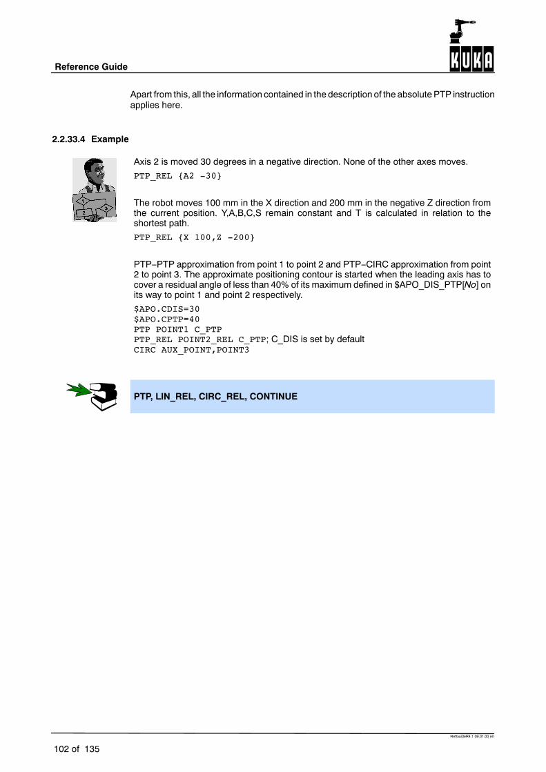
Reference Guide
102 of 135
RefGuideR4.1 09.01.00 en
Apart from this, all the information contained in the description of the absolute PTP instructionapplies here.
2.2.33.4 Example
Axis 2 is moved 30 degrees in a negative direction. None of the other axes moves.PTP_REL {A2 -30}
The robot moves 100 mm in the X direction and 200 mm in the negative Z direction fromthe current position. Y,A,B,C,S remain constant and T is calculated in relation to theshortest path.PTP_REL {X 100,Z -200}
PTP--PTP approximation from point 1 to point 2 and PTP--CIRC approximation from point2 to point 3. The approximate positioning contour is started when the leading axis has tocover a residual angle of less than 40% of its maximum defined in $APO_DIS_PTP[No] onits way to point 1 and point 2 respectively.$APO.CDIS=30$APO.CPTP=40PTP POINT1 C_PTPPTP_REL POINT2_REL C_PTP; C_DIS is set by defaultCIRC AUX_POINT,POINT3
PTP, LIN_REL, CIRC_REL, CONTINUE

2 Reference section (continued)
103 of 135
RefGuideR4.1 09.01.00 en
PULSE
2.2.34 PULSE
2.2.34.1 Brief information
Activation of a pulse output.
2.2.34.2 Syntax
PULSE (Signal, Level, Pulse_Duration)
Argument Type ExplanationSignal BOOL Output to which the pulse is to be fed. The following
are permitted:
OUT[No] Signal variable
Level BOOL Logical expression:
TRUE represents a positive pulse output (high) FALSE represents a negative pulse (low)
Pulse_Duration
REAL Arithmetic expression specifying the pulse duration.Values range from 0.1 to 3.0 seconds. The pulseinterval is 0.1 seconds, i.e. the pulse duration isrounded up or down accordingly.
2.2.34.3 Description
The PULSE statement is used for activating a pulse output. When the program statement isexecuted, the binary output is set to a defined level for a specified period of time. After thepulse duration has elapsed, the output signal is automatically reset by the system. The outputsignal is set and reset irrespective of the previous length of the output.
If an output with an opposite level is activated during a pulse, the pulse is shortened. If a pulseoutput is activated again before the falling edge, the pulse duration restarts. In the case ofpulse outputs with a positive level, the binary output is set to TRUE; in the case of pulseoutputs with a falling level, the binary output is set to FALSE.
Because the PULSE statement is executed internally by the controller at the low--priorityclock rate, a tolerance in the order of the pulse interval is produced (0.1 seconds). The timedeviation is about 1% -- 2% on average. The deviation is about 13% for very short pulses.

Reference Guide
104 of 135
RefGuideR4.1 09.01.00 en
Pulse times outside the permitted interval are only detected when the programis running; they trigger a program stop.
A maximum of 16 pulse outputs may be programmed simultaneously. The programmed pulse time continues to elapse in the event of a process stop. In the case of RESET and CANCEL, on the other hand, the pulse is terminated. The active pulse can be influenced by interrupts. The PULSE statement triggers an advance run stop. Only in the TRIGGER
statement is it executed concurrently with robot motion. If the program reaches the END statement during an active pulse, the pulse is
not terminated. If a pulse output is programmed before the first motion block, the pulse duration
also elapses if the Start key is released again and the robot has not yet reachedthe path (BCO).
The pulse is not terminated in the event of an Emergency Stop, an operator stop oran error stop!
2.2.34.4 Example
If a pulse output is activated again before the falling edge, the pulse duration restarts.
PULSE($OUT[50],TRUE,0.5)PULSE($OUT[50],TRUE,0.5)Output 50
If an output is already set before the pulse, it will be reset by the falling edge of the pulse.
$OUT[50]=TRUEPULSE($OUT[50],TRUE,0.5)Output 50
If the same output is set during the pulse duration, it will be reset by the falling edge of thepulse output.
PULSE($OUT[50],TRUE,0.5)$OUT[50]=TRUEOutput 50
If output 50 is reset during the pulse duration, the pulse duration is reduced accordingly.

2 Reference section (continued)
105 of 135
RefGuideR4.1 09.01.00 en
PULSE($OUT[50],TRUE,0.5)$OUT[50] = FALSEOutput 50
If a negative pulse is applied to the same output during the pulse duration of a positive pulse,the positive level is immediately set to Low and then reset to High after the pulse durationhas elapsed.
PULSE($OUT[50],TRUE,0.5)PULSE($OUT[50],FALSE,0.5)Output 50
If a negative pulse is applied to an output that is set to Low, the output remains Low until theend of the pulse and is then set to High.
$OUT[50] = FALSEPULSE($OUT[50],FALSE,0.5)Output 50
If an output is reset and then set again during a pulse, the output is reset again at the endof the pulse.
PULSE($OUT[50],TRUE,0.8)Output manipulationOutput 50
If a pulse is programmed before the END statement, the duration of program execution isincreased accordingly.
PULSE($OUT[50],TRUE,0.8)END statementProgram activeOutput 50
If program execution is reset or aborted (RESET/CANCEL) while a pulse output is active, thepulse is immediately reset.
PULSE($OUT[50],TRUE,0.8)RESET or CANCELOutput 50

Reference Guide
106 of 135
RefGuideR4.1 09.01.00 en
REPEAT ... UNTIL
2.2.35 REPEAT ... UNTIL
2.2.35.1 Brief information
Program loop that is always executed at least once (non--rejecting loop). The terminationcondition is checked at the end of the loop.
2.2.35.2 Syntax
REPEATStatementsUNTIL Termination_Condition
Argument Type ExplanationTermination_Condition
BOOL Logical expression which can contain a Booleanvariable, a Boolean function call or a logicaloperation with a Boolean result, e.g. a comparison.
2.2.35.3 Description
The REPEAT loop is repeated depending on a condition specified by the user.
This termination condition is checked after each loop execution. The statement block isalways executed at least once.If the logic condition has the value FALSE, the statement block is repeated. If the logiccondition has the value TRUE, the program is resumed at the next statement after thecondition.
2.2.35.4 Example
The loop is executed 100 times. R has the value 101 after the last loop execution.R=1REPEAT
R=R+1UNTIL R>100
The loop is to be executed until $IN[1] is true.REPEAT
StatementsUNTIL $IN[1]==TRUE
The loop is executed once, even though the termination condition is already fulfilledbefore the loop execution. The termination condition is not checked until the end of theloop. After exiting the loop, R has the value 102.R=101REPEAT
R=R+1UNTIL R>100

2 Reference section (continued)
107 of 135
RefGuideR4.1 09.01.00 en
EXIT, SWITCH, FOR, WHILE, LOOP

Reference Guide
108 of 135
RefGuideR4.1 09.01.00 en
RESUME
2.2.36 RESUME
2.2.36.1 Brief information
Aborting of subprograms and interrupt routines.
2.2.36.2 Syntax
RESUME
2.2.36.3 Description
TheRESUMEstatement is only executed during the processing of interrupts. It can thereforeonly be used in a module that is initiated by an interrupt. All active interrupt routines andsubprograms up to the level at which the current interrupt was declared are aborted byRESUME.
At the time that the RESUME statement is reached the variable $ADVANCE must be equal to 0 (no advance run). the advance run pointer must not be at the level at which the interrupt
was declared; it must be at least one level below this (otherwise theprogram is stopped and has to be reset!).
The motion after RESUME should not be a circular motion (CIRC) because thestart point is different each time (different circles).
Changing the variable $BASE in the interrupt routine only has an effect there. An $ADVANCE assignment cannot be used in the interrupt routine.

2 Reference section (continued)
109 of 135
RefGuideR4.1 09.01.00 en
2.2.36.4 Example
The robot is to search for a part on a pre--programmed path. The part can be detectedby a sensor connected to input 15. After locating the part, the robot is not to continue tothe end point of the path, but is to return to the interrupt position, pick up the part andtake it to the setdown point.DEF PROG() ; Main program...INTERRUPT DECL 1 WHEN $IN[15] DO FOUND()...PTP HOMEPOS...SEARCH() ; Search path must be programmed in a subprogram!LIN SETDOWN POINT...END
DEF SEARCH() ; Subprogram for searching for the partLIN START_POINT C_DISLIN TARGET_POINT$ADVANCE=0 ; No advance run permittedEND
DEF FOUND() ; Interrupt routineINTERRUPT OFF ; So that the interrupt routine is not executed twiceBRAKELIN $POS_INT ; Return to point where interrupt occurred... ; Pick up partRESUME ; Abort search pathEND
INTERRUPT DECL, INTERRUPT, BRAKE, RETURN

Reference Guide
110 of 135
RefGuideR4.1 09.01.00 en
RETURN
2.2.37 RETURN
2.2.37.1 Brief information
Return from functions and subprograms.
2.2.37.2 Syntax
For functions:
RETURN Function_Value
For subprograms:
RETURN
Argument Type ExplanationFunction_Value
The data typemust correspondto the functiontype
The function value is the value that istransferred when exiting a function.
2.2.37.3 Description
The RETURN statement is used in functions or subprograms. It ends the execution of thefunction or subprogram and causes the system to return to the calling module.
RETURN statement in functions
The execution of functions must be ended by a RETURN statement containing the functionvalue that has been determined. The function value can be specified as a constant, a variableor an expression. The data type must agree with the defined data type of the function in theDEFFCT declaration.
RETURN statement in subprograms
The RETURN statement may only consist of the keyword RETURN in the statement sectionof subprograms. It may not contain an expression. Function values cannot be transferred.

2 Reference section (continued)
111 of 135
RefGuideR4.1 09.01.00 en
2.2.37.4 Example
Return from functions to the calling module and transfer of the function value 0.RETURN 0
Return from functions to the calling module and transfer of the function value(X*3.1415)/360.RETURN (X*3.1415)/360
Return from functions to the calling module and transfer of the function value X.DEFFCT INT X()
INT XRETXRET=10RETURN XRET
ENDFCT
Return from the subprogram to the calling module.DEF PROG_2()
DeclarationsStatements
RETURNEND
DEFFCT, DEF

Reference Guide
112 of 135
RefGuideR4.1 09.01.00 en
SIGNAL
2.2.38 SIGNAL
2.2.38.1 Brief information
Declaration of signal names for input and output signals.
Interrupting the transfer of system states to the periphery.
2.2.38.2 Syntax
Declaration of signal names for input and output signals:
SIGNAL Signal_Name Interface_Name �TO Interface_Name
Interrupting the transfer of system states to the periphery:
SIGNAL System_Signal_Name FALSE
Argument Type ExplanationSignal_Name Any symbolic name.Interface_Name
Type of the predefined signal variable. The followingtypes can be selected:
$IN[No] binary inputs $OUT[No] binary outputs $DIGIN[No] digital inputs $ANIN[No] analog inputs $ANOUT[No] analog outputs
No refers to the corresponding inputs or outputs of thecontroller.
System_Signal_Name
Name of a predefined binary system output, e.g. $T1.
FALSE System state is not transferred to the periphery. Theoption TRUE is not available.
2.2.38.3 Description
The robot controller has two classes of interface:
1. simple process interfaces (signals)
2. logic interfaces (channels)
All of the interfaces are addressed using symbolic names. Your own Interface_Names(symbolic names) are logically combined with the predefined signal variables by means ofthe SIGNAL instruction. SIGNAL declarations must appear in the declaration section. Anoutput may appear in several SIGNAL statements. The number of signal numberscorresponds to the number of inputs or outputs that the controller has. As can be seen fromthe predefined signal variable names, there is a further distinction between binary and digitalinputs or outputs. In the case of binary inputs or outputs, inputs or outputs are addressedindividually. In the case of digital signals, several inputs or outputs are combined.
Several successive binary inputs or outputs can also be combined to form one digital inputor output using the instruction SIGNAL and the TO option. The signals combined in this waycan be optionally addressed with a decimal name, a hexadecimal name (prefix H) or with a

2 Reference section (continued)
113 of 135
RefGuideR4.1 09.01.00 en
bit pattern name (prefix B). They can also be processedwith Boolean operators. Amaximumof 32 binary signals can be combined to form one digital signal. To combine signals, bothpredefined signal names must be binary inputs or outputs and describe a continuouslyascending sequence with their index. A maximum of 32 inputs or outputs can be combined.
The robot controller can be fitted with an input/output module providing 32 inputs and 32outputs. Outputs 1 to 28 have a load rating of 100 mA and outputs 29 to 32 have a 2 Acapacity. Unused outputs can be used as flags. The signal name is declared internally asbeing of type BOOL in the case of binary inputs or outputs and of type Integer in the caseof digital inputs or outputs.
2.2.38.4 Example
The binary output $OUT[7] is assigned to the symbolic name Switch. The switch($OUT[7]) is set.SIGNAL SWITCH $OUT[7]
Switch = TRUE
The binary inputs $IN[1] to $IN[8] are combined to form one digital input under thesymbolic name INWORD.SIGNAL INWORD $IN[1] TO $IN[8]
The binary outputs $OUT[1] to $OUT[8] are combined to form one digital output underthe symbolic name OUTWORD. The outputs $OUT[3], $OUT[4], $OUT[5] and $OUT[7]are set by the digital output $OUTWORD.SIGNAL OUTWORD $ OUT[1] TO $ OUT[8]
OUTWORD = ‘B01011100’
ANIN, ANOUT, DIGIN, CHANNEL

Reference Guide
114 of 135
RefGuideR4.1 09.01.00 en
SREAD
2.2.39 SREAD
2.2.39.1 Brief information
The “SREAD” statement breaks a data set (text string) down into its constituent parts.
2.2.39.2 Syntax
SREAD (String1, State, Offset, Format, String2, Value, Var)
Argument Type Explanation
String1 CHAR[ ] The manipulated, transferred String2 is read from thischaracter array.
State STATE_T This structure returns information about the state fromthe kernel system, which the user can evaluate.STATE.MSG_NO If an error occurs during
execution of a command, thisvariable contains the errornumber.
CMD_OK Command successfullyexecuted
CMD_ABORT Command not successfullyexecuted
FMT_ERR Incorrect format specificationor non--corresponding variable.
State variable:HITS Number of correctly written
formatsLENGTH Length of the “%s” format that
occurs first in the format.
Offset INT Specifies the position from which String1 is copied intoString2.
Format CHAR[ ] The variable “Format” contains the format of the textthat is to be generated.
String2 CHAR[ ] String1 is copied into the character array.
VALUE INTREALBOOL
Data are pasted into this variable, from String1, with theformat specified.Boolean values are output as 0 or 1, ENUM values asnumbers.
Var The variables corresponding to “Format”.
2.2.39.3 Description
The “SREAD” command is used for processing character strings. Unlike with “CREAD”, datais not read from an open channel but from a variable.
The conversion specification for the variable Format has the following structure:

2 Reference section (continued)
115 of 135
RefGuideR4.1 09.01.00 en
%FWGU
The following definitions apply here:
G F Formatting character +, --, #, etc. (optional).
G W Width, specifies the minimum number of bytes that are to be output (optional).
G G Precision, its significance is dependent on the conversion character.’.’ or ’.*’ or ’.integer’ can be used (optional).
G U Permissible conversion characters: d, e, f, g, i, s, x and %.The system cannot distinguish between upper and lower--case letters.
By entering a width, you can specify to how many bytes the value is to be extended orcompressed. REAL values are an exception here.
When compressing the value, the high--order bytes are disregarded; the value is extendedby adding zero bytes at the end (little endian format).
If the width is not specified, the internal representation is output: 4 bytes for INTEGER, REALand ENUM, one byte for BOOL and CHAR.
The incorrect format can be inferred from the value of HITS (see below).
The types and values are checked in accordance with the following table at run time:
Format
Variable
%d
%i
%x
%f
%e
%g
%s %c
(3)
%1.
hWDHi
r
(3)
%2.
hWDHi
r
(3)
%4.
hWDHi
r
(3)
%.
hWDHi
r
(Signal)INT
X -- -- X -- -- -- --
INT array -- -- -- -- X X X X
REAL X X -- -- -- -- -- --
REALarray -- -- -- -- -- -- X X
(Signal)BOOL (1) X -- -- X -- -- -- --
BOOLarray -- -- -- -- X X X X
ENUM (2) X -- -- X -- -- -- --
ENUMarray -- -- -- -- X X X X
CHAR X -- -- X -- -- -- --
CHARarray -- -- X -- X -- -- X

Reference Guide
116 of 135
RefGuideR4.1 09.01.00 en
Remarks
G Every value that is not equal to 0 (zero) is converted to TRUE
G The system checks whether the value is a permissible ENUM value. If it is not, readingis aborted. ENUM begins at 1.
G If there are not enough data available to satisfy the requirements of the format, nothingis read for this format and the SREAD statement is aborted. The ignored data are,however, still ready for reading.
G Only as many bytes as can fit into the variable are read. The rest are still ready forreading. If the array is actually big enough but the number of available bytes is not amultiple of the size of an array element, the redundant bytes for the following format orfor the next SREAD statement are left for reading.
2.2.39.4 Example
Reading the content of the variable HUGO using formatting charactersINT OFFSET
DECL STATE_T STATEDECL CHAR HUGO[20]
OFFSET=0HUGO[]=”1234567890”SREAD(HUGO[],STATE,OFFSET,%01d%02d,VAR1,VAR2)
;Result: VAR1=1; VAR2=23
When reading with “SREAD”, it is necessary to define a “Format”.
In our example this corresponds to: %01d Number of characters to be read, hereone, therefore in VAR1 the first numberin HUGO, i.e. 1.
%02d Number of characters to be read, heretwo, therefore in VAR2 the second andthird numbers in HUGO, i.e. 2 and 3.

2 Reference section (continued)
117 of 135
RefGuideR4.1 09.01.00 en
STRUC
2.2.40 STRUC
2.2.40.1 Brief information
Declaration of structure data types.
2.2.40.2 Syntax
�GLOBAL STRUC Structure_Type_NameData_Type1 Component_Name1 ��,..., Component_NameM,...,Data_TypeN Component_NameN �,..., Component_NameZ
Argument Type ExplanationGLOBAL The keyword GLOBAL is used to identify the
structure, including in external programs, and mayonly be used in data lists.
Structure_Type_Name
Name of the structure data type.
Data_Type Any datatypes
The components of a structure type may be of anydata type. Structure types can also be used ascomponents; this is called a nested structure type.Arrays can be used as components of a structuretype if they have the type CHAR and areone--dimensional. In this case, the array limit followsthe name of the array in square brackets in thedefinition of the structure type.
Component_Name
The individual elements of a structure type are calledstructure components. A data type and a name aredefined for each component of a structure. Thecomponent name must be unambiguous within thestructure type.
The keyword GLOBAL, in the context of declaring structure data types, may only be usedin data lists.
2.2.40.3 Description
A structure type is a complex data type consisting of several identical or different data types.AXIS, FRAME, POS, E6POS and E6AXIS are important predefined structure types. Nostructure types having these names may be defined by the user.
As a user, you can freely define further structure types using the structure type declarationSTRUC. The STRUC definition for a freely defined structure type must occur before thedeclaration of variables of this type, both in terms of its actual position in the program andin terms of when it will be reached by the system. The following sequencemust be observed:first the STRUC declaration, then the declaration of variables.

Reference Guide
118 of 135
RefGuideR4.1 09.01.00 en
The following applies here:
G The predefined data list $CONFIG is located before the data lists that are local to themodule.
G A data list that is local to a module is located before its module.
Accessing components of structure variables
The components of a structure variable can be processed individually. To identify them, aperiod, followed by the name of the structure components, is added to the variable name. Inorder to be able to access a component of the internal structure in the case of a structure nest,string the variable name, the name of the external structure components and the name ofthe internal structure components together, separating them by means of a period.
Assigning values to structure variables
A value can be assigned individually to each component of structure variables by using avalue assignment. To assign values to several or all of the components of a structure variableat the same time, use an aggregate. When declaring the structure variable in the data list,you can assign an aggregate to it as its default initial value.
The names of structure types should end in _TYPE so as to distinguish them from variablenames.
2.2.40.4 Example
Declaration of a structure type W1_TYPE with the components CURRENT, VOLTAGEand FEED of data type REAL.STRUC W1_TYPE REAL CURRENT, VOLTAGE, FEED
Declaration of a structure type W2_TYPE with the component CURRENT of data typeREAL and of the array component TEXT[80] of data type CHAR.STRUC W2_TYPE REAL CURRENT, CHAR TEXT[80]
The following information is to be transferred in a variable to a subprogram for arcwelding: Wire speed Characteristic With/without arc in simulationDEF PROG()STRUC W_TYPE REAL WIRE,INT CHARAC,BOOL ARCDECL W_TYPE W_PARAMETERW_PARAMETER.WIRE=10.2; Individual initialization of the componentsW_PARAMETER.CHARAC=60W_PARAMETER.ARC=TRUEW_UP(W_PARAMETER); Call of the welding subprogram...
; Initialization with the aid of an aggregateW_PARAMETER={WIRE 7.3, CHARAC 50, ARC TRUE}W_UP(W_PARAMETER); Another call of the welding subprogram...END
ENUM, DECL

2 Reference section (continued)
119 of 135
RefGuideR4.1 09.01.00 en
SWITCH ... CASE ... ENDSWITCH
2.2.41 SWITCH ... CASE ... ENDSWITCH
2.2.41.1 Brief information
Choice between several statement branches.
2.2.41.2 Syntax
SWITCH Selection_CriterionCASE Block_Identifier1 �,Block_Identifier2,...Statements...�CASE Block_IdentifierN �,Block_IdentifierM,...Statements�DEFAULTDefault_StatementsENDSWITCH
Argument Type ExplanationSelection_Criterion
INT, CHAR,enumerationtype
The selection criterion can be a variable, a functioncall or an expression of the specified data type.
Block_Identifier
INT, CHAR,enumerationtype
The identifiers for the relevant CASE blocks mayonly be integer character or enumeration constants.The type of the constants must agree with the typeof the selection criterion. There must be at least oneblock identifier.
You can specify as many block identifiers as youwant to one program branch. If the same blockidentifier is used repeatedly, only the first branchhaving this identifier is executed. The remainingprogram branches are disregarded. Several blockidentifiers are separated from each other by acomma.
2.2.41.3 Description
The SWITCH statement is a selection instruction for various program branches. A selectioncriterion is assigned a certain value ahead of theSWITCHstatement. If this value agreeswitha block identifier, the corresponding branch is executed and the program jumps straight tothe ENDSWITCH statement without taking subsequent block identifiers into consideration.If no block identifier agrees with the selection criterion, the DEFAULT statement block isexecuted, if there is one; otherwise, the program resumes at the statement afterENDSWITCH.
Several block identifiers can be assigned to one program branch. On the other hand, it is notsensible to use one block identifier several times, as only the first branch with thecorresponding identifier will ever be taken into consideration.

Reference Guide
120 of 135
RefGuideR4.1 09.01.00 en
The data types for the selection criterion and the block identifier must correspond.
A SWITCH statement must contain at least one CASE statement; it must be ensured that noblank lines or comments appear between the SWITCH instruction and the first CASEstatement.
The DEFAULT statement can be omitted. The default statement may only occur once in aSWITCH statement.
The SWITCH statement cannot be prematurely exited using the EXIT statement.
2.2.41.4 Example
Selection criterion and block identifier are of type Integer. The DEFAULT statement isused here to output an error message.SWITCH VERSION
CASE 1SP_1(); Call of the subprogram SP_1
CASE 2,3SP_2(); Call of the subprogram SP_2SP_3(); Call of the subprogram SP_3SP_3A(); Call of the subprogram SP_3a
DEFAULTERROR_SP(); Call of the subprogram ERROR_SP
ENDSWITCH
Selection criterion and block identifier are of type Character. The statement SP_5() isnever executed here because the block identifier “JOHN” appears twice.SWITCH NAME
CASE ”ALFRED”SP_1(); Call of the subprogram SP_1
CASE ”BERT”,”JOHN”SP_2(); Call of the subprogram SP_2SP_3(); Call of the subprogram SP_3
CASE ”JOHN”SP_5(); Call of the subprogram SP_5
ENDSWITCH
EXIT, FOR, REPEAT, WHILE, LOOP

2 Reference section (continued)
121 of 135
RefGuideR4.1 09.01.00 en
SWRITE
2.2.42 SWRITE
2.2.42.1 Brief information
The “SWRITE” statement makes it possible to combine several data to form a data set.
2.2.42.2 Syntax
SWRITE (String1, State, OFFSET, Format, String2, VALUE)
Argument Type Explanation
String1 CHAR[ ] The manipulated String2 is written in this characterarray.
State
STATE_T
This structure returns information about the state fromthe kernel system, which the user can evaluate.STATE.MSG_NO If an error occurs during
execution of a command, thisvariable contains the errornumber.
CMD_OK Command successfullyexecuted
CMD_ABORT Command not successfullyexecuted
State variable:HITS Number of correctly written
formats.
OFFSET INT Specifies the position from which String2 is copied intoString1.
Format CHAR[ ] The variable “Format” contains the format of the textthat is to be generated.
String2
CHAR[ ]
This character array is copied into the character arrayString1. String2 may also contain formatting characters,which paste the content of the variable “VALUE” in thisposition with the format specified.
VALUE INTREALBOOL
The content of this variable is pasted into String2 withthe format specified.Boolean values are output as 0 or 1, ENUM values asnumbers.
2.2.42.3 Description
The “SWRITE” command is used for processing character strings. Unlike with “CWRITE”,data is not written to an open channel, but to a variable.
The conversion specification for the variable Format has the following structure:
%FWGU
The following definitions apply here:
G F Formatting character +, --, #, etc. (optional).
G W Width, specifies the minimum number of bytes that are to be output (optional).

Reference Guide
122 of 135
RefGuideR4.1 09.01.00 en
G G Precision, its significance is dependent on the conversion character.’.’ or ’.*’ or ’.integer’ can be used (optional).
G U Permissible conversion characters: c, d, e, f, g, i, s, x and %.The system cannot distinguish between upper and lower--case letters.
By entering a width, you can specify to how many bytes the value is to be extended orcompressed. REAL values are an exception here.
When compressing the value, the high--order bytes are disregarded; the value is extendedby adding zero bytes at the end (little endian format).
If the width is not specified, the internal representation is output: 4 bytes for INTEGER, REALand ENUM, one byte for BOOL and CHAR.
The incorrect format can be inferred from the value of HITS (see below).
Format
Variable
%d
%i
%x
%f
%e
%g
%s %c %1.
hWDHi
r
%2.
hWDHi
r
%4.
hWDHi
r
%.
hWDHi
r
(Signal)INT
X X -- -- -- -- -- --
INT array -- -- -- -- X X X X
REAL -- X -- -- -- -- -- --
REALarray -- -- -- -- -- -- X X
(Signal)BOOL X -- -- -- -- -- -- --
BOOLarray -- -- -- -- X X X X
ENUM X -- -- -- -- -- -- --
ENUMarray -- -- -- -- X X X X
CHAR X -- -- X -- -- -- --
CHARarray -- -- X -- X -- -- X
The “SWRITE” statement, which can be used in programs at the control or robot levels,triggers an advance run stop.

2 Reference section (continued)
123 of 135
RefGuideR4.1 09.01.00 en
2.2.42.4 Example
Copy the content of the variable HUGO into the variable BERTAINT OFFSETDECL STATE_T STATEDECL CHAR HUGO[20]DECL CHAR BERTA[20]
OFFSET=0HUGO[]= “TEST”BERTA[]=” “SWRITE(BERTA[],STATE,OFFSET,HUGO[])
;Result: BERTA[]=“TEST”;as “OFFSET” called by reference,this variable now has the value 4;repeat the same command
SWRITE(BERTA[],STATE,OFFSET,HUGO[]);Result: BERTA[]=“TESTTEST”
OFFSET=OFFSET+1SWRITE(BERTA[],STATE,OFFSET,HUGO[])
;Result: BERTA[]=“TESTTEST TEST”
Use of formatting charactersINT OFFSETINT NODECL STATE_T STATDECL CHAR HUGO[20]DECL CHAR BERTA[20]
NO=1OFFSET=0HUGO[]=”TEST%d”BERTA[]=” “SWRITE(BERTA[],STATE,OFFSET,HUGO[],NO)
;Result: BERTA[]=“TEST1“
OFFSET=OFFSET+1NO=22SWRITE(BERTA[];STATE,OFFSET,HUGO[],NO)
;Result: BERTA[]=“TEST1TEST22”

Reference Guide
124 of 135
RefGuideR4.1 09.01.00 en
TRIGGER WHEN DISTANCE ... DO
2.2.43 TRIGGER WHEN DISTANCE ... DO
2.2.43.1 Brief information
Path--related triggering of a switching action parallel to the robot motion.
2.2.43.2 Syntax
TRIGGER WHEN DISTANCE=Distance DELAY=Time DO Statement�PRIO=Priority
Argument Type ExplanationDistance INT Variable or constant specifying where the switching
operation is to occur:
DISTANCE=0 at the start DISTANCE=1 at the end
of the motion block. Only these two values may beassigned!
Time INT Variable or constant that can be used for delayingand advancing the switching operation. If the valueis
positive, execution of the statement isdelayed
negative, execution of the statement isadvanced by a specified time.
The unit is milliseconds.
Statement The instruction can be
an assignment of a value to a variable or a PULSE statement or a subprogram call
Subprograms are executed like interrupt routines.The desired priority must therefore be specified bymeans of the operation PRIO.
Priority INT Variable or constant specifying the priority of theinterrupt. Every Trigger statement with a subprogramcall must be assigned a priority. Priority levels 1...39and 81...128 are available. Priority levels 40 to 80are reserved for the system and are allocatedautomatically if the value –1 is entered for thepriority. A level 1 interrupt has the highest priority.
2.2.43.3 Description
The TRIGGER statement can be used to execute a subprogram or to assign a value to avariable parallel to the next robot motion depending on a distance criterion.
The path relation is defined by specifying whether the switching operation is to occur at thebeginning of the motion block or at the end by means of the parameter Distance:

2 Reference section (continued)
125 of 135
RefGuideR4.1 09.01.00 en
G For single blocks, DISTANCE=0 indicates the start point and
G DISTANCE=1 the target point
of the followingmotion. In the case of approximate positioning blocks, DISTANCE=1 signifiesthe middle of the following approximate positioning arc. If the previous block is already anapproximate positioning block, DISTANCE=0 signifies the target point of the precedingapproximate positioning arc.
It is possible to delay or advance the statement by a specified period of time using theDELAYoption. The switching point can, however, only be delayed or advanced in so far as it stillremains in the block concerned. An automatic limitation takes place at the block limits. Soin the case of a single block and DISTANCE=1, the switching point cannot be moved pastthe target point and further along the path by specifying a positive DELAY value. Specifyinga negative DELAY value ensures that the switching operation has already occurred beforethe target point is reached. But even here, the switching point can be advanced no furtherthan the start point of the motion.
2.2.43.4 Example
Switching operation 130 milliseconds after the start of the next motion; setting of asignal.TRIGGER WHEN DISTANCE=0 DELAY=130 DO $OUT[8]=TRUE
Switching operation at the end of the next motion; call of a subprogram with priority 5.TRIGGER WHEN DISTANCE=1 DO QUOTIENT(DIVIDEND,DIVISOR)PRIO=5
Switching ranges with different motion sequences and DELAY options.DEF PROG()...PTP POINT0TRIGGER WHEN DISTANCE=0 DELAY=40 DO A=12
; Switching range: 0 -- 1TRIGGER WHEN DISTANCE=1 DELAY=-20 DO SP1() PRIO=10
; Switching range: 0 -- 1LIN POINT1TRIGGER WHEN DISTANCE=0 DELAY=10 DO SP2(A) PRIO=5
; Switching range: 1 -- 2’BTRIGGER WHEN DISTANCE=1 DELAY=15 DO B=1
; Switching range: 2’B -- 2’ELIN POINT2 C_DISTRIGGER WHEN DISTANCE=0 DELAY=10 DO SP2(B) PRIO=12
; Switching range: 2’E -- 3’BTRIGGER WHEN DISTANCE=1 DO SP(A,B,C) PRIO=6
; Switching range: 3’B --3’ELIN POINT3 C_DISTRIGGER WHEN DISTANCE=0 DELAY=50 DO SP2(A) PRIO=4
; Switching range: 3’E -- 4TRIGGER WHEN DISTANCE=1 DELAY=-80 DO A=0
; Switching range: 3’E -- 4LIN POINT4...END

Reference Guide
126 of 135
RefGuideR4.1 09.01.00 en
A=12
1 22’B
2’E
3’B
3’E
0
3 4
2’
3’
SP1()
SP2(A)
B=1
SP2(B)
SP(A,B,C)SP2(A)A=0
INTERRUPT DECL, INTERRUPT, PULSE

2 Reference section (continued)
127 of 135
RefGuideR4.1 09.01.00 en
TRIGGER WHEN PATH ... DO
2.2.44 TRIGGER WHEN PATH ... DO
2.2.44.1 Brief information
Path--related and delayed triggering of a switching action parallel to the robot motion.
2.2.44.2 Syntax
TRIGGER WHEN PATH=Distance DELAY=Time DO Statement�PRIO=Priority
Argument Type ExplanationDistance INT Specifies, in mm, the distance at which the switching
operation is triggered relative to the target point ofthe next motion. If the switching operation is to betriggered before the target point, the value forDistance must be negative. If Distance is positive,the switching operation is triggered after the targetpoint.If the target point is approximated, the start point forDistance is the center point of the approximatepositioning motion.With a positive value for Distance, it is possible toshift the switching point as far as the next exactpositioning point programmed after the trigger.With a negative value for Distance, the switchingpoint can be shifted back as far as the start point.If the start point is approximated, the switching pointcan be shifted as far as the start of the approximatepositioning range.
Time INT The specification “Time” is used to delay or advancethe switching point relative to the Path specificationby a defined amount of time.The switching point can only be shifted within theswitching range specified above.The unit is milliseconds.

Reference Guide
128 of 135
RefGuideR4.1 09.01.00 en
Statement The instruction can be
an assignment of a value to a variable or a PULSE statement or a subprogram call�
Subprograms are executed like interrupt routines.The desired priority must therefore be specified bymeans of the operation PRIO.
Priority INT Variable or constant specifying the priority of theinterrupt. Every Trigger statement with a subprogramcall must be assigned a priority. Priority levels 1...39and 81...128 are available. Priority levels 40 to 80are reserved for the system and are allocatedautomatically if the value –1 is entered for thepriority. A level 1 interrupt has the highest priority.
2.2.44.3 Description
If you are using the path--related TRIGGER statement, you can trigger the switching actionat any position along the path by specifying a distance. As with “Trigger when Distance”, thisagain can additionally be delayed or brought forward.
The conditions governing the position on the path at which the distance criterion is evaluated,dependent on an approximate positioning motion, are shown in the table above. The timecriterion is always calculated from the Path specification. The switching range is againdependent on the approximate positioning and is shown in the table above.
Instruction sequence:
⋮LIN POINT2 C_DISTRIGGER WHEN PATH = Y DELAY= X DO $OUT[2]=TRUELIN POINT3 C_DISLIN POINT4 C_DISLIN POINT5⋮
Since the switching point can be shifted from the motion point before which it wasprogrammed, past all subsequent approximate positioning points, as far as the next exactpositioning point, it is possible to shift the switching point from the approximate positioningstart point POINT2 to POINT5. If POINT2 was not approximated in this sequence ofinstructions, the switching point could only be shifted as far as the exact positioning pointPOINT2.
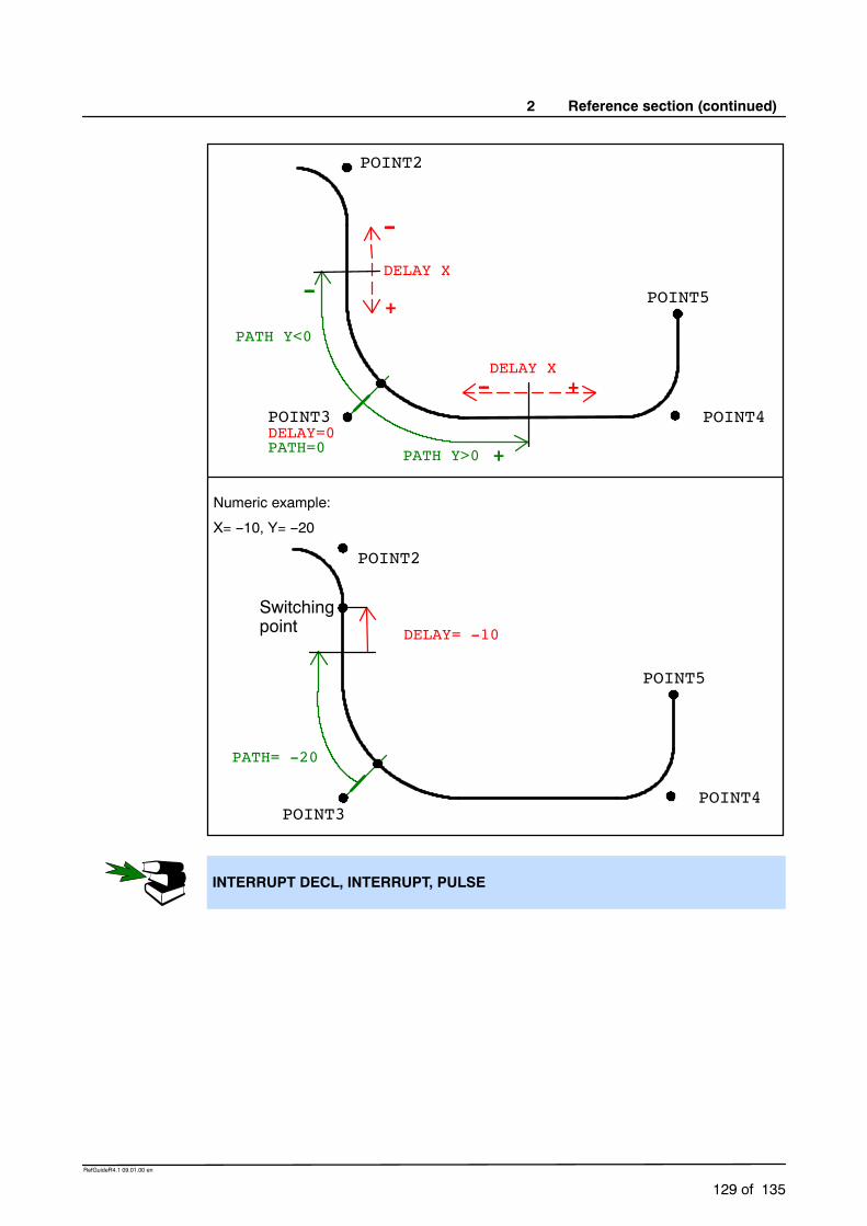
2 Reference section (continued)
129 of 135
RefGuideR4.1 09.01.00 en
+
-- +DELAY X
POINT4POINT3
POINT2
-- POINT5
PATH=0 PATH Y>0
DELAY=0
--
+
DELAY X
PATH Y<0
POINT4POINT3
POINT2
POINT5
PATH= -20
Switchingpoint DELAY= -10
Numeric example:
X= --10, Y= --20
INTERRUPT DECL, INTERRUPT, PULSE

Reference Guide
130 of 135
RefGuideR4.1 09.01.00 en
WAIT FOR
2.2.45 WAIT FOR
2.2.45.1 Brief information
Wait for a continue condition.
2.2.45.2 Syntax
WAIT FOR Continue_Condition
Argument Type ExplanationContinue_Condition
BOOL Logical expression used for specifying the conditionwhen program execution is to be continued:
if the logical expression is already TRUE whenWAIT is called, program execution is not halted.
if the logical expression is FALSE, programexecution is halted until the expression has thevalue TRUE.
2.2.45.3 Description
The WAIT statement halts execution of the program and continues it after a specified waittime. The length of the wait time is determined by the occurrence of the programmed event.
If, due to incorrect formulation, the expression can never take the value TRUE, thecompiler does not recognize this. In this case, execution of the program will bepermanently halted because the program is waiting for a condition that cannot befulfilled.
2.2.45.4 Example
Interruption of program execution until $IN[17] is TRUE.WAIT FOR $IN[17]
Interruption of program execution until BIT1 is FALSE.WAIT FOR BIT1 == FALSE
WAIT SEC

2 Reference section (continued)
131 of 135
RefGuideR4.1 09.01.00 en
WAIT SEC
2.2.46 WAIT SEC
2.2.46.1 Brief information
Wait times.
2.2.46.2 Syntax
WAIT SEC Wait_Time
Argument Type ExplanationWait_Time INT, REAL Arithmetic expression used for specifying the
number of seconds that program execution is to beinterrupted for. If the value is negative, the programdoes not wait. With small wait times, the accuracy isdetermined by a multiple of the interpolation cycle.
2.2.46.3 Description
The WAIT statement halts execution of the program and continues it after a specified waittime. The length of the wait time is specified in seconds.
2.2.46.4 Example
Interruption of program execution for 17.156 seconds.WAIT SEC 17.156
Interruption of program execution in accordance with the variable value of V_WAIT inseconds.WAIT SEC V_WAIT
WAIT FOR

Reference Guide
132 of 135
RefGuideR4.1 09.01.00 en
WHILE ... ENDWHILE
2.2.47 WHILE ... ENDWHILE
2.2.47.1 Brief information
Program loop; termination condition is checked at the beginning of the loop(rejecting loop).
2.2.47.2 Syntax
WHILE Repetition_ConditionStatementsENDWHILE
Argument Type ExplanationRepetition_Condition
BOOL Logical expression which can contain a Booleanvariable, a Boolean function call or a logicaloperation with a Boolean result, e.g. a comparison.
2.2.47.3 Description
The WHILE loop is repeated depending on a condition specified by the user. This repetitioncondition is checked before each loop execution. The statement block is never executed ifthe repetition condition is not already fulfilled beforehand.
The statement block is executed if the logic condition has the value TRUE, i.e. the repetitioncondition is fulfilled. If the logic condition has the value FALSE, the program is resumed withthe next instruction after ENDWHILE. Each WHILE statement must be ended by anENDWHILE statement.
2.2.47.4 Example
The loop is executed 99 times. W has the value 100 after exiting the loop.W=1WHILE W<100
W=W+1ENDWHILE
The loop is executed until $IN[1] is true.WHILE $IN[1]==TRUE
StatementsENDWHILE
The loop is never executed because the repetition condition is not already satisfiedbefore the loop is executed. After exiting, W has the value 100.W=100WHILE W<100
W=W+1ENDWHILE

2 Reference section (continued)
133 of 135
RefGuideR4.1 09.01.00 en
EXIT, SWITCH, FOR, REPEAT, LOOP

Reference Guide
134 of 135
RefGuideR4.1 09.01.00 en
2.3 System functions
VARSTATE()
2.3.1 VARSTATE()
2.3.1.1 Brief information
Polls the state of a variable. VARSTATE() is a function with a return value of type“VAR_STATE”:
ENUM VAR_STATE DECLARED, INITIALIZED, UNKNOWN
The declaration of VARSTATE:
VAR_STATE VARSTATE(CHAR VAR_STR[80]:IN)
2.3.1.2 Syntax
DECL VAR_STATE Variable_Name
Variable_Name = VARSTATE(”Variable”)
Argument Type ExplanationVariable_Name
VAR_STATE Any variable name.
Variable any Name of a variable for which the state is to bedetermined.
2.3.1.3 Description
The function VARSTATE can be used to determine the state of a variable. The return valueof the function can take the Enum constants DECLARED, INITIALIZED or UNKNOWN.

2 Reference section (continued)
135 of 135
RefGuideR4.1 09.01.00 en
2.3.1.4 Example
DEF PROG1()INT A,BCHAR STR[5]A=99STR[]=“A”
IF VARSTATE(“A”)==#DECLARED THEN; This IF condition is incorrect as A has not only been declared, but has also alreadybeen initialized.$OUT[1]=TRUEENDIF
IF VARSTATE(“A”)==#INITIALIZED THEN; This IF condition is correct.$OUT[2]=TRUEENDIF
IF VARSTATE(“A”)==#UNKNOWN THEN; This IF condition is incorrect.$OUT[3]=TRUEENDIF
IF VARSTATE(“B”)==#DECLARED THEN; This IF condition is correct.$OUT[4]=TRUEENDIF
IF VARSTATE(”NOTHING”)==#UNKNOWN THEN; This IF condition is correct, assuming that there is no variable with the name“NOTHING” in $CONFIG.DAT.$OUT[5]=TRUEENDIF
IF VARSTATE(STR[])==#INITIALIZED THEN; This IF condition is correct as A has already been initialized.$OUT[6]=TRUEENDIF
END
1

Index
Index -- i
Symbols
:SER_1, 27:SER_2, 27, 41$CMD, 27, 48$CUSTOM.DAT, 27%FWGU, 49, 115, 121|, 9
A
ABS, 43, 45Active reading, 44ANIN, 20ANOUT, 22Areas of validity, 16Arithmetic operators, 13ASYNC, 48AXIS, 12
B
Bit operators, 13Block structure, 15BOOL, 11BRAKE, 24
C
C Programming Language, 45CCLOSE, 25CHANNEL, 27Channel_Name, 27, 41CHAR, 11CIRC, 29CIRC_REL, 34CMD_ABORT, 25, 43, 48, 121CMD_OK, 25, 43, 48, 121CMD_REJ, 48CMD_STAT, 43, 48CMD_SYN, 48CMD_TIMEOUT, 43Comment, 14COND, 43, 45CONFIRM, 38Constants, 12CONTINUE, 40Continuous--path motions, 15Control structures, 15Conversion character, 45
COPEN, 41CP motions, 15CREAD, 42CWRITE, 48
D
Data lists, 11Data types, 11DATA_BLK, 43DATA_END, 43DATA_OK, 43, 48DECL, 53Declaration, 14DEF...END, 57DEFDAT...ENDDAT, 60DEFFCT...ENDFCT, 63DIGIN, 66
E
E6AXIS, 12E6POS, 12ENUM, 68ENUM value, 46, 116EXIT, 70Expression, 14EXT, 71EXTFCT, 73
F
FMT_ERR, 43, 48FOR ... TO ... ENDFOR, 76Format, 44, 45, 49, 114, 121FPRINTF, 49FRAME, 12Functions, 15
G
Geometric operator, 13GOTO, 78
H
HALT, 79Handle, 25, 41, 42, 48HITS, 43, 48, 121

Index
Index -- ii
I
IEEE 754 standard format, 45IF ... THEN ... ENDIF, 80Implicit data type assignment, 12
Implicit type conversion, 12IMPORT... IS, 81Initialization, 14
INT, 11INT $DATA_SER1, 42, 44INT $DATA_SER2, 42, 44
Interface_Name, 27INTERRUPT, 86INTERRUPT DECL ... when ... do, 83
K
Keywords, 16
L
LENGTH, 43LIN, 90
LIN_REL, 94Literals, 11Little endian format, 45
Logic operators, 13LOOP ... ENDLOOP, 96
PTP, 97PTP_REL, 101
M
Maximum line length, 16Mode, 43, 48Modules, 11
MODUS_T, 43, 48Motion programming, 15
N
Names, 11
O
OFFSET, 121Offset, 44, 114Operators, 13
P
Passive reading, 44Point--to--point motions (PTP), 15POS, 12Predefined data types, 12Priority of operators, 14PULSE, 103
R
REAL, 11Relational operators, 13REPEAT ... UNTIL, 106RESUME, 108RETURN, 110
S
SEQ, 43SER_1, 27, 44SER_2, 27, 44SIGNAL, 112Simple data types, 11SREAD, 114State, 25, 43, 45, 48, 114, 121STATE.MSG_NO, 121STATE_T, 27, 43, 48Statement, 14String1, 114, 121String2, 114, 121STRUC, 117, 121Structure_Variable, 27Subprograms, 15SWITCH... CASE... ENDSWITCH, 119SWRITE, 121SYNC, 48System variables, 13
T
Timeout, 44TRIGGER WHEN DISTANCE ... DO, 124TRIGGER WHEN PATH ... DO, 127
V
VALUE, 114, 121Var, 44, 49Variables, 13VARSTATE(), 134

Index
Index -- iii
WWait, 44WAIT FOR, 130WAIT SEC, 131WHILE ... ENDWHILE, 132