ks permaglide plain bearings - kramp.com · • lifetime lubrication • low wear • very good...
TRANSCRIPT

KS Permaglide®
Plain BearingsCatalogue 2015
OriginalKS PERMAGLIDE®
Plain Bearings
2 | Catalogue KS Permaglide® plain bearings
MotorserviceThe Motorservice Group is the sales organisation for the global aftermarket activities of KSPG (Kolbenschmidt Pierburg). It is one of the leading suppliers of engine components for the independent aftermarket, including the premium brands KOLBENSCHMIDT, PIERBURG and TRW Engine Components, as well as the BF brand.
KS GleitlagerWithin the Kolbenschmidt Pierburg Group, KS Gleitlager is the specialist for high-precision bearings. The introduction of new technologies in production and surface finishing, innovative material developments and a clear customer focus have made KS Gleitlager one of the world’s leading suppliers of engine plain bearings and dry plain bearings (KS Permaglide®).
KSPG (Kolbenschmidt Pierburg)As long-standing partners to the automotive industry, the companies in the KSPG Group develop innovative components and system solutions with acknowledged competence for air supply and emission control, for oil and water pumps, for pistons, engine blocks and engine bearings. The products comply with the high demands and quality standards of the automotive industry. Low emission, reduced fuel consumption, reliability, quality and safety – these are the forces that drive innovation at KSPG.
LiabilityAll information in this brochure has been carefully researched and compiled. Nevertheless, it is possible that errors have occurred, information has been translated incorrectly, information is missing or the details provided have changed in the intervening time. As a result, we are unable to provide any guarantee nor to accept any legal liability for the accuracy, com-pleteness, currency or quality of the information provided. We hereby waive all liability for any damages, whether direct or indirect in nature and whether tangible or intangible, resulting from the use or misuse of information or from incomplete or incorrect information in this brochure, unless proven to be the result of deliberate intent or negligence on our part. The parts outlined in the catalogue are not designed for use in aircraft. Names, descriptions and numbers of products, man-ufacturers, etc. are included for the purpose of comparison only.
Permaglide® is a registered trademark of KS Gleitlager GmbH
4th edition 11.2014Articel No. 50 003 863-02
Editorial department:Motorservice, Product Management
Layout and production:Motorservice, Marketing DIE NECKARPRINZEN GmbH, Heilbronn
This document must not be reprinted, duplicated or translated in full or in part without our prior written consent and without reference to the source of the material.
All content including pictures and diagrams is subject to alteration. No liability accepted.
Published by:© MS Motorservice International GmbH
Catalogue KS Permaglide® plain bearings | 3
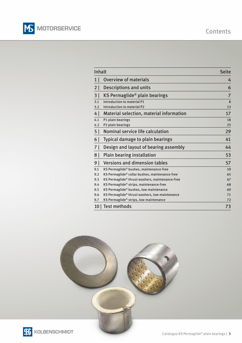
Contents
Inhalt Seite
1 | Overview of materials 4
2 | Descriptions and units 6
3 | KS Permaglide® plain bearings 73.1 Introduction to material P1 83.2 Introduction to material P2 13
4 | Material selection, material information 174.1 P1 plain bearings 184.2 P2 plain bearings 25
5 | Nominal service life calculation 29
6 | Typical damage to plain bearings 41
7 | Design and layout of bearing assembly 44
8 | Plain bearing installation 53
9 | Versions and dimension tables 579.1 KS Permaglide® bushes, maintenance-free 599.2 KS Permaglide® collar bushes, maintenance-free 659.3 KS Permaglide® thrust washers, maintenance-free 679.4 KS Permaglide® strips, maintenance-free 689.5 KS Permaglide® bushes, low-maintenance 699.6 KS Permaglide® thrust washers, low-maintenance 719.7 KS Permaglide® strips, low-maintenance 72
10 | Test methods 73
4 | Catalogue KS Permaglide® plain bearings
1 | Overview of materials
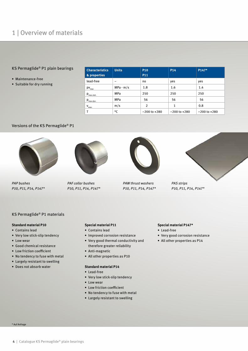
KS Permaglide® P1 plain bearings
• Maintenance-free• Suitable for dry running
Characteristics& properties
Units P10P11
P14 P147*
lead-free – no yes yes
pvmax MPa · m/s 1.8 1.6 1.4
pmax.stat. MPa 250 250 250
pmax.dyn. MPa 56 56 56
vmax. m/s 2 1 0.8
T °C –200 to +280 –200 to +280 –200 to +280
Versions of the KS Permaglide® P1
PAP bushes PAF collar bushes PAW thrust washers PAS stripsP10, P11, P14, P147* P10, P11, P14, P147* P10, P11, P14, P147* P10, P11, P14, P147*
KS Permaglide® P1 materials
* Auf Anfrage
Standard material P10• Contains lead• Very low stick-slip tendency• Low wear• Good chemical resistance• Low friction coefficient• No tendency to fuse with metal• Largely resistant to swelling• Does not absorb water
Special material P11• Contains lead• Improved corrosion resistance• Very good thermal conductivity and
therefore greater reliability• Anti-magnetic• All other properties as P10
Standard material P14• Lead-free• Very low stick-slip tendency• Low wear• Low friction coefficient• No tendency to fuse with metal• Largely resistant to swelling
Special material P147*• Lead-free• Very good corrosion resistance• All other properties as P14
Catalogue KS Permaglide® plain bearings | 5
Overview of materials | 1
Characteristics & properties
Unit P20 P22*, P23*
P200 P202*, P203*
lead-free – no yes
pvmax MPa · m/s 3 3.3
pmax.stat. MPa 250 250
pmax.dyn. MPa 70 70
vmax. m/s 3 3.3
T °C –40 to +110 –40 to +110
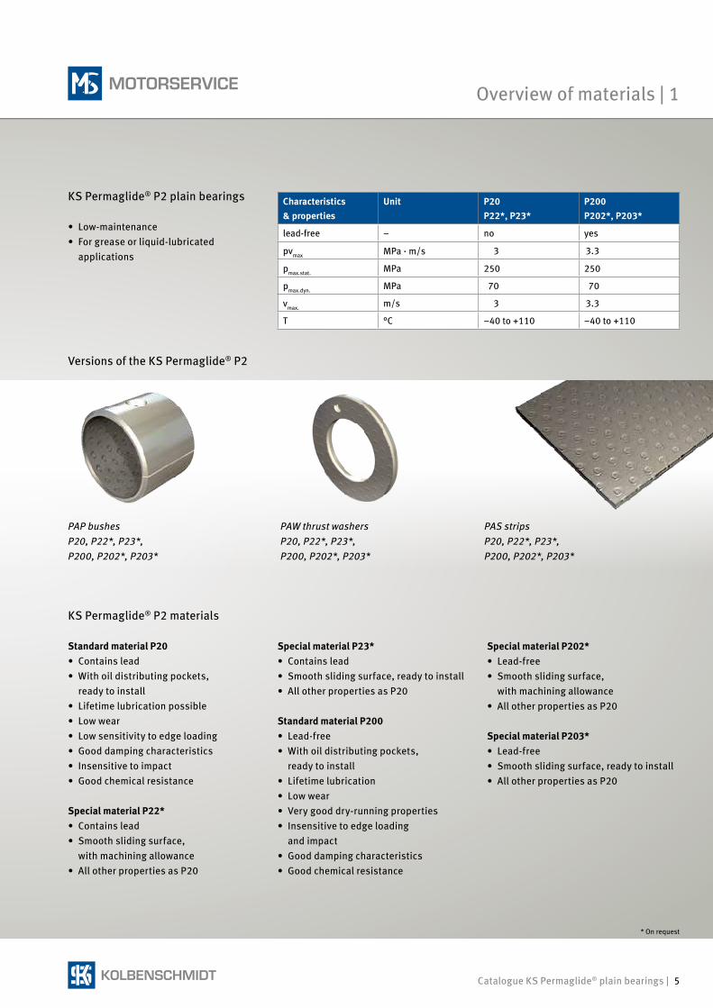
KS Permaglide® P2 plain bearings
• Low-maintenance• For grease or liquid-lubricated applications
KS Permaglide® P2 materials
Versions of the KS Permaglide® P2
PAP bushes PAW thrust washers PAS stripsP20, P22*, P23*, P20, P22*, P23*, P20, P22*, P23*, P200, P202*, P203* P200, P202*, P203* P200, P202*, P203*
* On request
Standard material P20• Contains lead• With oil distributing pockets,
ready to install• Lifetime lubrication possible• Low wear• Low sensitivity to edge loading• Good damping characteristics• Insensitive to impact• Good chemical resistance
Special material P22*• Contains lead• Smooth sliding surface, with machining allowance• All other properties as P20
Special material P23*• Contains lead• Smooth sliding surface, ready to install• All other properties as P20
Standard material P200• Lead-free• With oil distributing pockets,
ready to install• Lifetime lubrication• Low wear• Very good dry-running properties• Insensitive to edge loading and impact• Good damping characteristics• Good chemical resistance
Special material P202*• Lead-free• Smooth sliding surface, with machining allowance• All other properties as P20
Special material P203*• Lead-free• Smooth sliding surface, ready to install• All other properties as P20
6 | Catalogue KS Permaglide® plain bearings
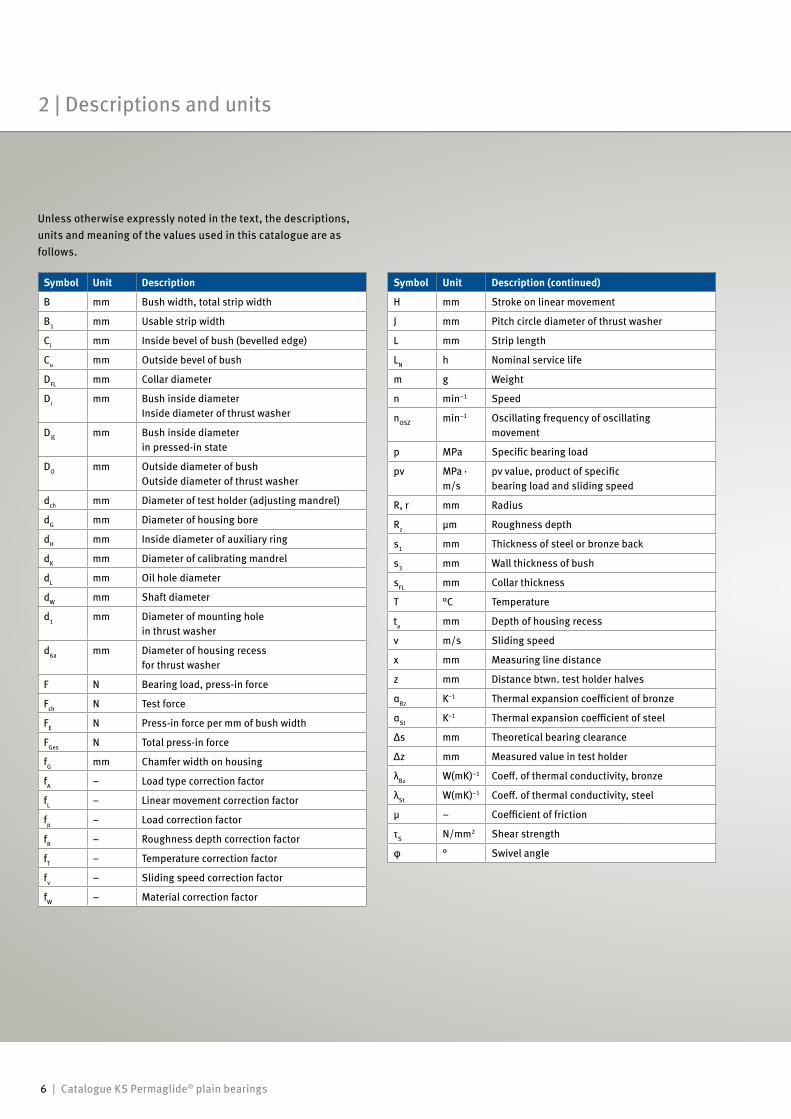
Unless otherwise expressly noted in the text, the descriptions, units and meaning of the values used in this catalogue are as follows.
2 | Descriptions and units
Symbol Unit Description
B mm Bush width, total strip width
B1 mm Usable strip width
Ci mm Inside bevel of bush (bevelled edge)
Co mm Outside bevel of bush
DFL mm Collar diameter
Di mm Bush inside diameterInside diameter of thrust washer
DiE mm Bush inside diameter in pressed-in state
DO mm Outside diameter of bushOutside diameter of thrust washer
dch mm Diameter of test holder (adjusting mandrel)
dG mm Diameter of housing bore
dH mm Inside diameter of auxiliary ring
dK mm Diameter of calibrating mandrel
dL mm Oil hole diameter
dW mm Shaft diameter
d1 mm Diameter of mounting hole in thrust washer
d6a mm Diameter of housing recess for thrust washer
F N Bearing load, press-in force
Fch N Test force
FE N Press-in force per mm of bush width
FGes N Total press-in force
fG mm Chamfer width on housing
fA – Load type correction factor
fL – Linear movement correction factor
fp – Load correction factor
fR – Roughness depth correction factor
fT – Temperature correction factor
fv – Sliding speed correction factor
fW – Material correction factor
Symbol Unit Description (continued)
H mm Stroke on linear movement
J mm Pitch circle diameter of thrust washer
L mm Strip length
LN h Nominal service life
m g Weight
n min–1 Speed
nOSZ min–1 Oscillating frequency of oscillating movement
p MPa Specific bearing load
pv MPa · m/s
pv value, product of specific bearing load and sliding speed
R, r mm Radius
Rz µm Roughness depth
s1 mm Thickness of steel or bronze back
s3 mm Wall thickness of bush
sFL mm Collar thickness
T °C Temperature
ta mm Depth of housing recess
v m/s Sliding speed
x mm Measuring line distance
z mm Distance btwn. test holder halves
αBz K–1 Thermal expansion coefficient of bronze
αSt K–1 Thermal expansion coefficient of steel
Δs mm Theoretical bearing clearance
Δz mm Measured value in test holder
λBz W(mK)–1 Coeff. of thermal conductivity, bronze
λSt W(mK)–1 Coeff. of thermal conductivity, steel
µ – Coefficient of friction
τS N/mm2 Shear strength
φ ° Swivel angle
Catalogue KS Permaglide® plain bearings | 7
1
23
4
5
6
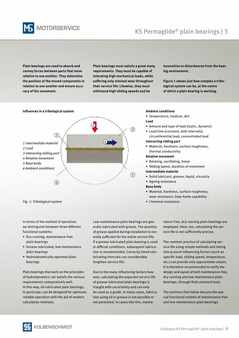
Plain bearings are used to absorb and convey forces between parts that move relative to one another. They determine the position of the moved components in relation to one another and ensure accu-racy of the movement.
Plain bearings must satisfy a great many requirements. They must be capable of tolerating high mechanical loads, while suffering only minimal wear throughout their service life. Likewise, they must withstand high sliding speeds and be
insensitive to disturbances from the bear-ing environment.
Figure 1 shows just how complex a tribo-logical system can be, at the centre of which a plain bearing is working.
Fig. 1: Tribological system
Ambient conditions• Temperature, medium, dirtLoad• Amount and type of load (static, dynamic)• Load time (constant, with intervals), circumferential load, concentrated loadInteracting sliding part• Material, hardness, surface roughness, thermal conductivityRelative movement• Rotating, oscillating, linear• Sliding speed, duration of movementIntermediate material• Solid lubricant, grease, liquid, viscosity• Ageing resistanceBase body• Material, hardness, surface roughness, wear resistance, limp-home capability • Chemical resistance
In terms of the method of operation, we distinguish between three different functional systems:• Dry-running, maintenance-free
plain bearings• Grease-lubricated, low-maintenance plain bearings• Hydrodynamically operated plain
bearings
Plain bearings that work on the principles of hydrodynamics can satisfy the various requirements comparatively well. In this way, oil-lubricated plain bearings, in particular, can be designed for optimum, reliable operation with the aid of modern calculation methods.
nance-free, dry-running plain bearings are employed. Here, too, calculating the ser-vice life is not sufficiently precise.
The common practice of calculating ser-vice life using simple methods and taking into account influencing factors (such as specific load, sliding speed, temperature, etc.) can provide only approximate values. It is therefore recommended to verify the design and layout of both maintenance-free, dry-running and low-maintenance plain bearings, through field-oriented tests.
The sections that follow discuss the spe-cial functional models of maintenance-free and low-maintenance plain bearings.
Low-maintenance plain bearings are gen-erally lubricated with grease. The quantity of grease applied during installation is nor-mally sufficient for the entire service life. If a grease-lubricated plain bearing is used in difficult conditions, subsequent lubrica-tion is recommended. Correctly timed relu-bricating intervals can considerably lengthen service life.
Due to the many influencing factors how-ever, calculating the expected service life of grease-lubricated plain bearings is fraught with uncertainty and can only be used as a guide. In many cases, lubrica-tion using oil or grease is not possible or not permitted. In cases like this, mainte-
KS Permaglide® plain bearings | 3
Influences in a tribological system
1 Intermediate material2 Load3 Interacting sliding part4 Relative movement5 Base body6 Ambient conditions
8 | Catalogue KS Permaglide® plain bearings
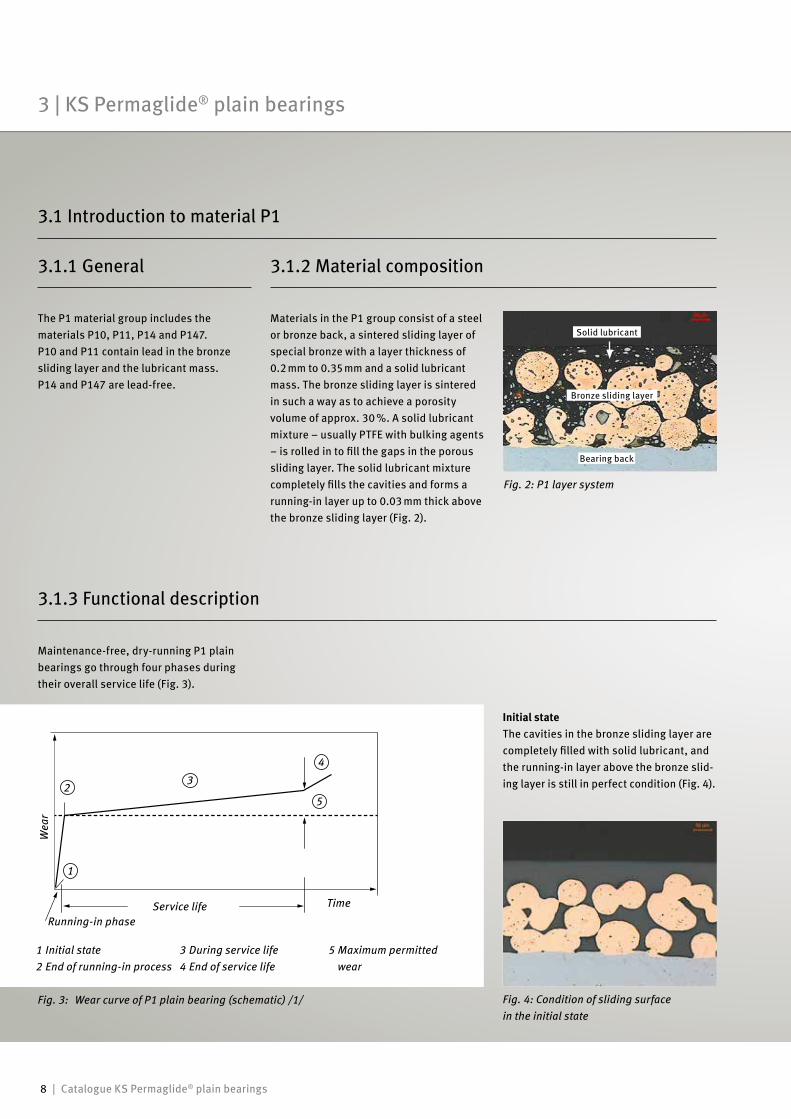
Fig. 2: P1 layer system
3.1.1 General
Materials in the P1 group consist of a steel or bronze back, a sintered sliding layer of special bronze with a layer thickness of 0.2 mm to 0.35 mm and a solid lubricant mass. The bronze sliding layer is sintered in such a way as to achieve a porosity volume of approx. 30 %. A solid lubricant mixture – usually PTFE with bulking agents – is rolled in to fill the gaps in the porous sliding layer. The solid lubricant mixture completely fills the cavities and forms a running-in layer up to 0.03 mm thick above the bronze sliding layer (Fig. 2).
3.1.3 Functional description
3 | KS Permaglide® plain bearings
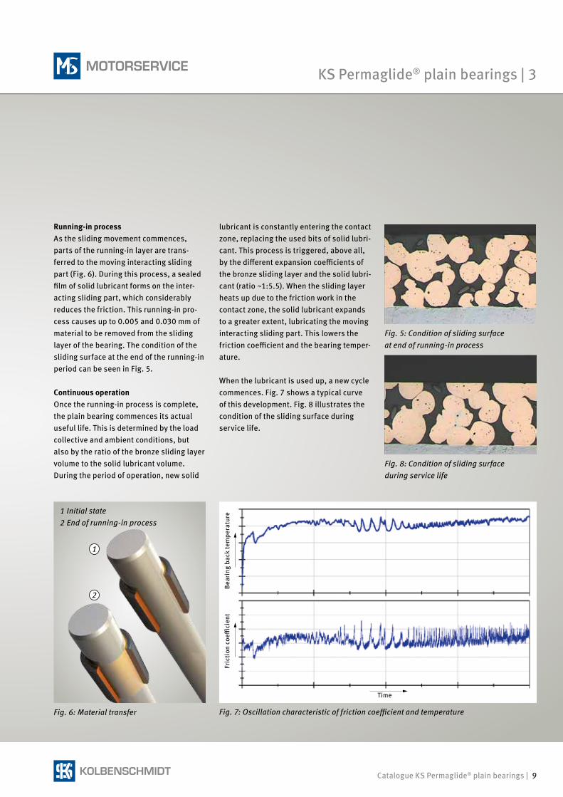
Fig. 3: Wear curve of P1 plain bearing (schematic) /1/ Fig. 4: Condition of sliding surface in the initial state
Solid lubricant
Bronze sliding layer
Bearing back
The P1 material group includes the materials P10, P11, P14 and P147.P10 and P11 contain lead in the bronze sliding layer and the lubricant mass.P14 and P147 are lead-free.
Maintenance-free, dry-running P1 plain bearings go through four phases during their overall service life (Fig. 3).
3.1.2 Material composition
3.1 Introduction to material P1
Initial stateThe cavities in the bronze sliding layer are completely filled with solid lubricant, and the running-in layer above the bronze slid-ing layer is still in perfect condition (Fig. 4).
1
23
4
5
Wea
r
Running-in phase
TimeService life
1 Initial state2 End of running-in process
3 During service life4 End of service life
5 Maximum permitted wear
Catalogue KS Permaglide® plain bearings | 9
1
2
Fig. 5: Condition of sliding surface at end of running-in process
Fig. 7: Oscillation characteristic of friction coefficient and temperature
Bea
ring
bac
k te
mpe
ratu
reFr
icti
on c
oeffi
cien
t
Time
Running-in processAs the sliding movement commences, parts of the running-in layer are trans-ferred to the moving interacting sliding part (Fig. 6). During this process, a sealed film of solid lubricant forms on the inter-acting sliding part, which considerably reduces the friction. This running-in pro-cess causes up to 0.005 and 0.030 mm of material to be removed from the sliding layer of the bearing. The cond ition of the sliding surface at the end of the running-in period can be seen in Fig. 5.
Continuous operationOnce the running-in process is complete, the plain bearing commences its actual useful life. This is determined by the load collective and ambient conditions, but also by the ratio of the bronze sliding layer volume to the solid lubricant volume. During the period of operation, new solid
Fig. 6: Material transfer
lubricant is constantly entering the contact zone, replacing the used bits of solid lubri-cant. This process is triggered, above all, by the different expansion coefficients of the bronze sliding layer and the solid lubri-cant (ratio ~1:5.5). When the sliding layer heats up due to the friction work in the contact zone, the solid lubricant expands to a greater extent, lubricating the moving interacting sliding part. This lowers the friction coefficient and the bearing temper-ature.
When the lubricant is used up, a new cycle commences. Fig. 7 shows a typical curve of this development. Fig. 8 illustrates the condition of the sliding surface during service life.
Fig. 8: Condition of sliding surface during service life
KS Permaglide® plain bearings | 3
1 Initial state2 End of running-in process
10 | Catalogue KS Permaglide® plain bearings
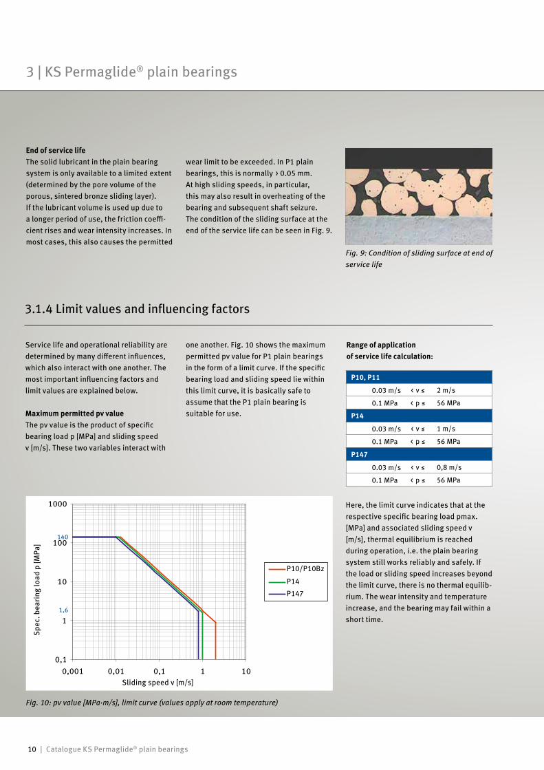
Fig. 10: pv value [MPa·m/s], limit curve (values apply at room temperature)
140
1,6
Service life and operational reliability are determined by many different influences, which also interact with one another. The most important influencing factors and limit values are explained below.
Maximum permitted pv valueThe pv value is the product of specific bearing load p [MPa] and sliding speed v [m/s]. These two variables interact with
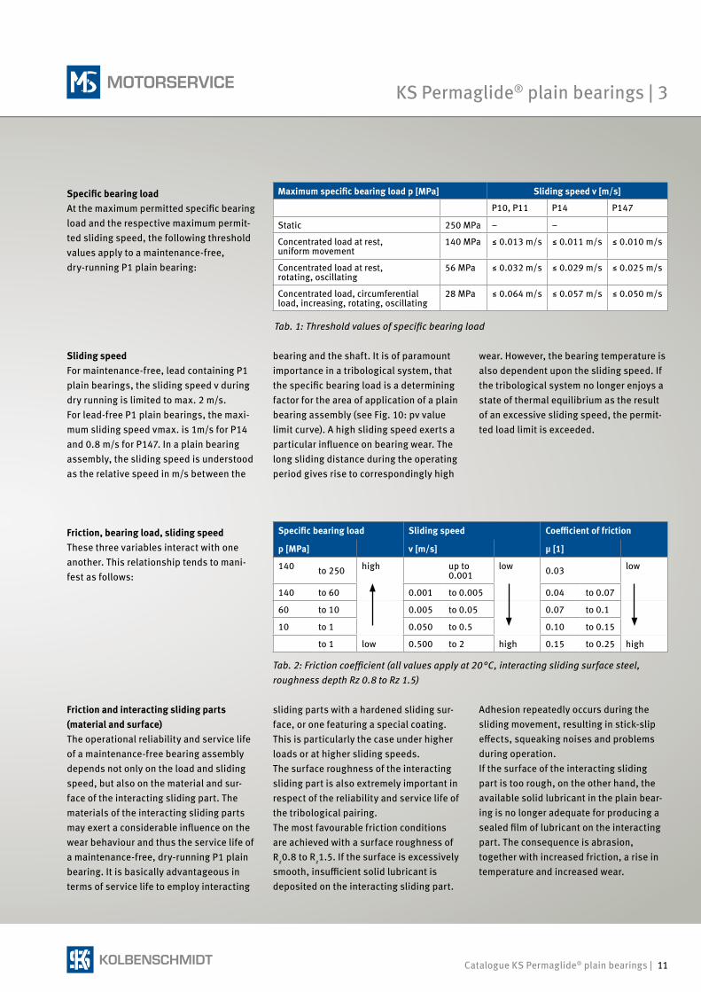
End of service lifeThe solid lubricant in the plain bearing system is only available to a limited extent (determined by the pore volume of the porous, sintered bronze sliding layer). If the lubricant volume is used up due to a longer period of use, the friction coeffi-cient rises and wear intensity increases. In most cases, this also causes the permitted
Here, the limit curve indicates that at the respective specific bearing load pmax. [MPa] and associated sliding speed v [m/s], thermal equilibrium is reached during operation, i.e. the plain bearing system still works reliably and safely. If the load or sliding speed increases beyond the limit curve, there is no thermal equilib-rium. The wear intensity and temperature increase, and the bearing may fail within a short time.
Range of application of service life calculation:
Fig. 9: Condition of sliding surface at end of service life
3.1.4 Limit values and influencing factors
P10, P11
0.03 m/s < v ≤ 2 m/s
0.1 MPa < p ≤ 56 MPa
P14
0.03 m/s < v ≤ 1 m/s
0.1 MPa < p ≤ 56 MPa
P147
0.03 m/s < v ≤ 0,8 m/s
0.1 MPa < p ≤ 56 MPa
Sliding speed v [m/s]
Spec
. bea
ring
load
p [M
Pa]
wear limit to be exceeded. In P1 plain bearings, this is normally > 0.05 mm. At high sliding speeds, in particular, this may also result in overheating of the bearing and subsequent shaft seizure. The condition of the sliding surface at the end of the service life can be seen in Fig. 9.
one another. Fig. 10 shows the maximum permitted pv value for P1 plain bearings in the form of a limit curve. If the specific bearing load and sliding speed lie within this limit curve, it is basically safe to assume that the P1 plain bearing is suitable for use.
3 | KS Permaglide® plain bearings
Catalogue KS Permaglide® plain bearings | 11
Specific bearing loadAt the maximum permitted specific bearing load and the respective maximum permit-ted sliding speed, the following threshold values apply to a maintenance-free, dry-running P1 plain bearing:
Sliding speed For maintenance-free, lead containing P1 plain bearings, the sliding speed v during dry running is limited to max. 2 m/s. For lead-free P1 plain bearings, the maxi-mum sliding speed vmax. is 1m/s for P14 and 0.8 m/s for P147. In a plain bearing assembly, the sliding speed is understood as the relative speed in m/s between the
Friction, bearing load, sliding speedThese three variables interact with one another. This relationship tends to mani-fest as follows:
bearing and the shaft. It is of paramount importance in a tribological system, that the specific bearing load is a determining factor for the area of application of a plain bearing assembly (see Fig. 10: pv value limit curve). A high sliding speed exerts a particular influence on bearing wear. The long sliding distance during the operating period gives rise to correspondingly high
wear. However, the bearing temperature is also dependent upon the sliding speed. If the tribological system no longer enjoys a state of thermal equilibrium as the result of an excessive sliding speed, the permit-ted load limit is exceeded.
Friction and interacting sliding parts (material and surface)The operational reliability and service life of a maintenance-free bearing assembly depends not only on the load and sliding speed, but also on the material and sur-face of the interacting sliding part. The materials of the interacting sliding parts may exert a considerable influence on the wear behaviour and thus the service life of a maintenance-free, dry-running P1 plain bearing. It is basically advantageous in terms of service life to employ interacting
sliding parts with a hardened sliding sur-face, or one featuring a special coating. This is particularly the case under higher loads or at higher sliding speeds.The surface roughness of the interacting sliding part is also extremely important in respect of the reliability and service life of the tribological pairing. The most favourable friction conditions are achieved with a surface roughness of Rz0.8 to Rz1.5. If the surface is excessively smooth, insufficient solid lubricant is deposited on the interacting sliding part.
Adhesion repeatedly occurs during the sliding movement, resulting in stick-slip effects, squeaking noises and problems during operation.If the surface of the interacting sliding part is too rough, on the other hand, the available solid lubricant in the plain bear-ing is no longer adequate for producing a sealed film of lubricant on the interacting part. The consequence is abrasion, together with increased friction, a rise in temperature and increased wear.
Maximum specific bearing load p [MPa] Sliding speed v [m/s]
P10, P11 P14 P147
Static 250 MPa – –
Concentrated load at rest, uniform movement
140 MPa ≤ 0.013 m/s ≤ 0.011 m/s ≤ 0.010 m/s
Concentrated load at rest, rotating, oscillating
56 MPa ≤ 0.032 m/s ≤ 0.029 m/s ≤ 0.025 m/s
Concentrated load, circumferential load, increasing, rotating, oscillating
28 MPa ≤ 0.064 m/s ≤ 0.057 m/s ≤ 0.050 m/s
Tab. 1: Threshold values of specific bearing load
Tab. 2: Friction coefficient (all values apply at 20 °C, interacting sliding surface steel, roughness depth Rz 0.8 to Rz 1.5)
Specific bearing load Sliding speed Coefficient of friction
p [MPa] v [m/s] μ [1]
140 to 250 high up to 0.001
low 0.03 low
140 to 60 0.001 to 0.005 0.04 to 0.07
60 to 10 0.005 to 0.05 0.07 to 0.1
10 to 1 0.050 to 0.5 0.10 to 0.15
to 1 low 0.500 to 2 high 0.15 to 0.25 high
KS Permaglide® plain bearings | 3
12 | Catalogue KS Permaglide® plain bearings
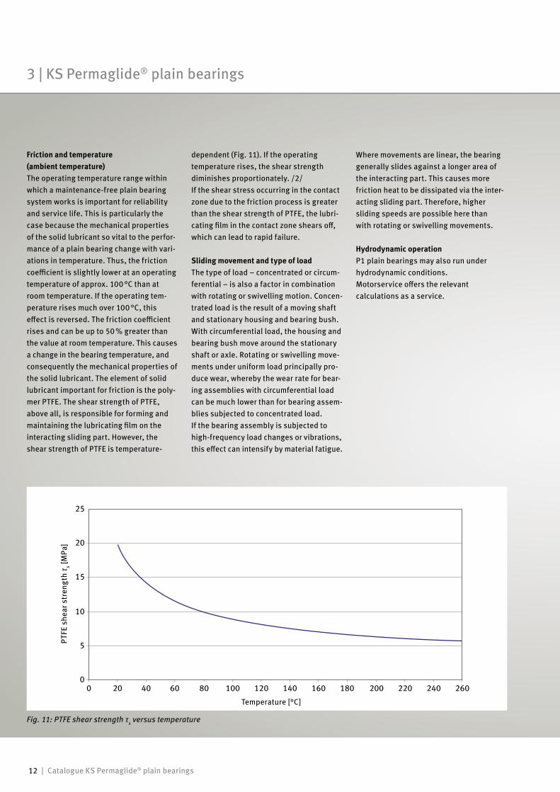
Fig. 11: PTFE shear strength τs versus temperature
Temperature [°C]
PTFE
she
ar s
tren
gth
τ s [MPa
]
Friction and temperature (ambient temperature)The operating temperature range within which a maintenance-free plain bearing system works is important for reliability and service life. This is particularly the case because the mechanical properties of the solid lubricant so vital to the perfor-mance of a plain bearing change with vari-ations in temperature. Thus, the friction coefficient is slightly lower at an operating temperature of approx. 100 °C than at room temperature. If the operating tem-perature rises much over 100 °C, this effect is reversed. The friction coefficient rises and can be up to 50 % greater than the value at room temperature. This causes a change in the bearing temperature, and consequently the mechanical properties of the solid lubricant. The element of solid lubricant important for friction is the poly-mer PTFE. The shear strength of PTFE, above all, is responsible for forming and maintaining the lubricating film on the interacting sliding part. However, the shear strength of PTFE is temperature-
dependent (Fig. 11). If the operating temperature rises, the shear strength diminishes proportionately. /2/If the shear stress occurring in the contact zone due to the friction process is greater than the shear strength of PTFE, the lubri-cating film in the contact zone shears off, which can lead to rapid failure.
Sliding movement and type of loadThe type of load – concentrated or circum-ferential – is also a factor in combination with rotating or swivelling motion. Concen-trated load is the result of a moving shaft and stationary housing and bearing bush. With circumferential load, the housing and bearing bush move around the stationary shaft or axle. Rotating or swivelling move-ments under uniform load principally pro-duce wear, whereby the wear rate for bear-ing assemblies with circumferential load can be much lower than for bearing assem-blies subjected to concentrated load. If the bearing assembly is subjected to high-frequency load changes or vibrations, this effect can intensify by material fatigue.
Where movements are linear, the bearing generally slides against a longer area of the interacting part. This causes more friction heat to be dissipated via the inter-acting sliding part. Therefore, higher sliding speeds are possible here than with rotating or swivelling movements.
Hydrodynamic operationP1 plain bearings may also run under hydrodynamic conditions.Motorservice offers the relevant calculations as a service.
3 | KS Permaglide® plain bearings
Catalogue KS Permaglide® plain bearings | 13
Sliding layer
Compound layer
Bearing back Test time [h]
Wea
r [µm
]
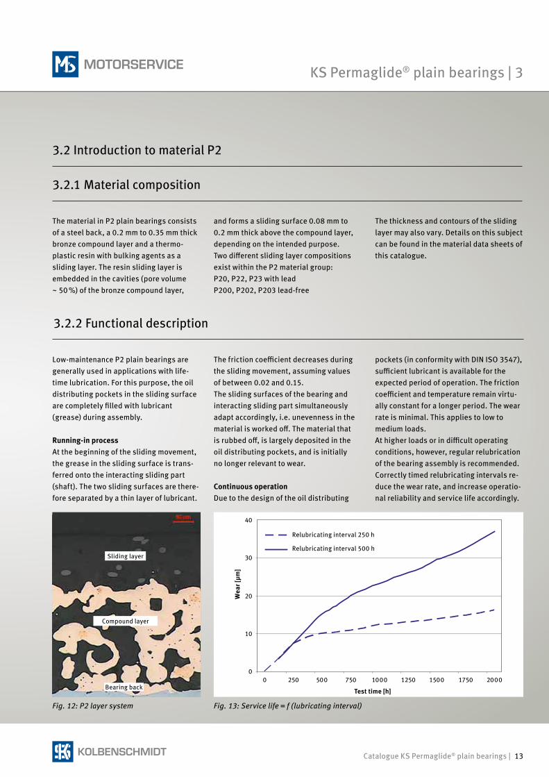
Relubricating interval 250 h
Relubricating interval 500 h
The material in P2 plain bearings consists of a steel back, a 0.2 mm to 0.35 mm thick bronze compound layer and a thermo- plastic resin with bulking agents as a sliding layer. The resin sliding layer is embedded in the cavities (pore volume ~ 50 %) of the bronze compound layer,
Low-maintenance P2 plain bearings are generally used in applications with life-time lubrication. For this purpose, the oil distributing pockets in the sliding surface are completely filled with lubricant (grease) during assembly.
Running-in processAt the beginning of the sliding movement, the grease in the sliding surface is trans-fer red onto the interacting sliding part (shaft). The two sliding surfaces are there-fore separated by a thin layer of lubricant.
Fig. 12: P2 layer system
The friction coefficient dec reases during the sliding movement, assum ing values of between 0.02 and 0.15. The sliding surfaces of the bearing and interacting sliding part simultaneously adapt accordingly, i.e. unevenness in the material is worked off. The material that is rubbed off, is largely deposited in the oil distributing pockets, and is initially no longer relevant to wear.
Continuous operationDue to the design of the oil distributing
Fig. 13: Service life = f (lubricating interval)
3.2.2 Functional description
3.2.1 Material composition
and forms a sliding surface 0.08 mm to 0.2 mm thick above the compound layer, depending on the intended purpose.Two different sliding layer compositions exist within the P2 material group:P20, P22, P23 with leadP200, P202, P203 lead-free
The thickness and contours of the sliding layer may also vary. Details on this subject can be found in the material data sheets of this catalogue.
pockets (in conformity with DIN ISO 3547), sufficient lubricant is available for the expected period of operation. The friction coefficient and temperature remain virtu-ally constant for a longer period. The wear rate is minimal. This applies to low to medium loads.At higher loads or in difficult operating conditions, however, regular relubrication of the bearing assembly is recommended.Correctly timed relubricating intervals re- duce the wear rate, and increase operatio- nal reliability and service life accordingly.
KS Permaglide® plain bearings | 3
3.2 Introduction to material P2
14 | Catalogue KS Permaglide® plain bearings
140
0.10.010.0010.1
Sliding speed v [m/s]
Spec
. bea
ring
load
p [M
Pa]
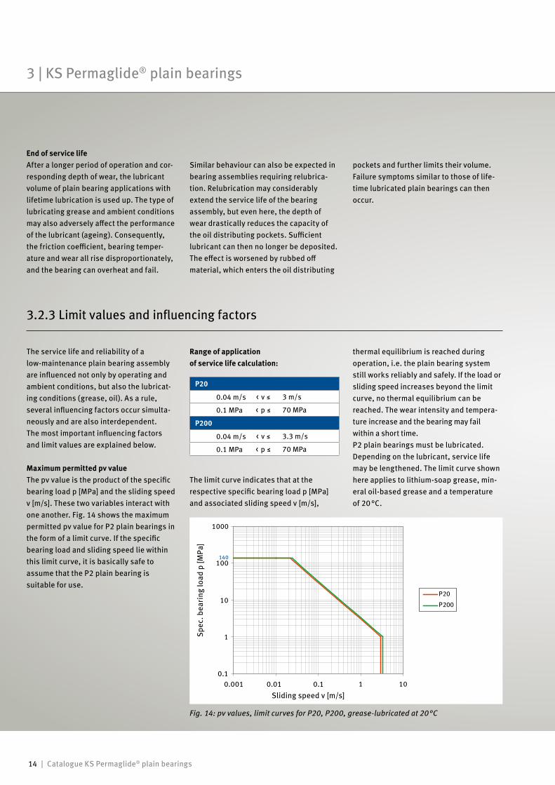
The service life and reliability of a low-maintenance plain bearing assembly are influenced not only by operating and ambient conditions, but also the lubricat-ing conditions (grease, oil). As a rule, several influencing factors occur simulta-neously and are also interdependent. The most important influencing factors and limit values are explained below.
Maximum permitted pv valueThe pv value is the product of the specific bearing load p [MPa] and the sliding speed v [m/s]. These two variables interact with one another. Fig. 14 shows the maximum permitted pv value for P2 plain bearings in the form of a limit curve. If the specific bearing load and sliding speed lie within this limit curve, it is basically safe to assume that the P2 plain bearing is suitable for use.
Fig. 14: pv values, limit curves for P20, P200, grease-lubricated at 20 °C
P20
0.04 m/s < v ≤ 3 m/s
0.1 MPa < p ≤ 70 MPa
P200
0.04 m/s < v ≤ 3.3 m/s
0.1 MPa < p ≤ 70 MPa
The limit curve indicates that at the respective specific bearing load p [MPa] and associated sliding speed v [m/s],
End of service lifeAfter a longer period of operation and cor-responding depth of wear, the lubricant volume of plain bearing applications with lifetime lubrication is used up. The type of lubricating grease and ambient conditions may also adversely affect the performance of the lubricant (ageing). Consequently, the friction coefficient, bearing temper-ature and wear all rise disproportion ately, and the bearing can overheat and fail.
Range of application of service life calculation:
3.2.3 Limit values and influencing factors
Similar behaviour can also be expected in bearing assemblies requiring relubrica-tion. Relubrication may considerably extend the service life of the bearing assembly, but even here, the depth of wear drastically reduces the capacity of the oil distributing pockets. Sufficient lubricant can then no longer be deposited. The effect is worsened by rubbed off material, which enters the oil distributing
pockets and further limits their volume. Failure symptoms similar to those of life-time lubricated plain bearings can then occur.
thermal equilibrium is reached during operation, i.e. the plain bearing system still works reliably and safely. If the load or sliding speed increases beyond the limit curve, no thermal equilibrium can be reached. The wear intensity and tempera-ture increase and the bearing may fail within a short time. P2 plain bearings must be lubricated. Depending on the lubricant, service life may be lengthened. The limit curve shown here applies to lithium-soap grease, min-eral oil-based grease and a temperature of 20 °C.
3 | KS Permaglide® plain bearings
Catalogue KS Permaglide® plain bearings | 15
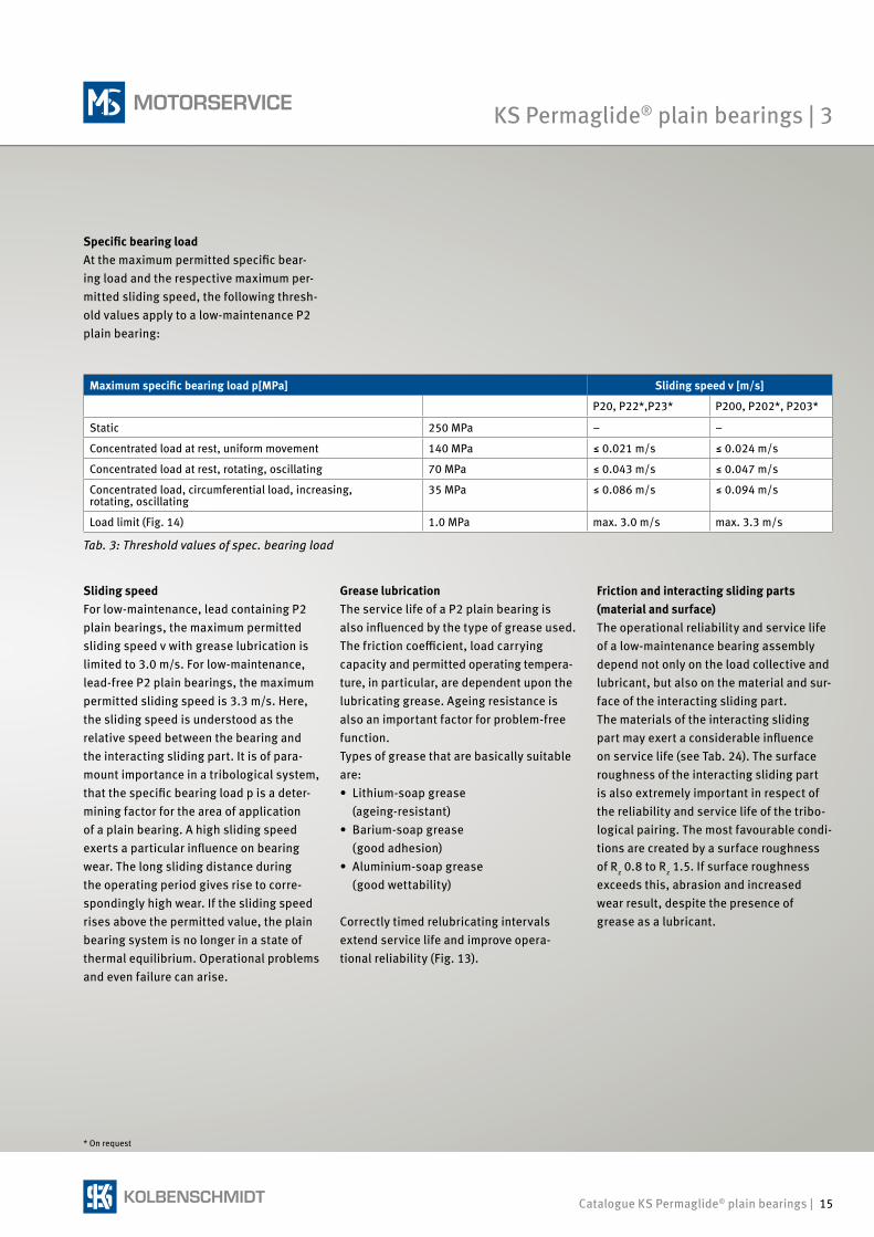
Specific bearing loadAt the maximum permitted specific bear-ing load and the respective maximum per-mitted sliding speed, the following thresh-old values apply to a low-maintenance P2 plain bearing:
Sliding speedFor low-maintenance, lead containing P2 plain bearings, the maximum permitted sliding speed v with grease lubrication is limited to 3.0 m/s. For low-maintenance, lead-free P2 plain bearings, the maximum permitted sliding speed is 3.3 m/s. Here, the sliding speed is understood as the relative speed between the bearing and the interacting sliding part. It is of para-mount importance in a tribological system, that the specific bearing load p is a deter-mining factor for the area of application of a plain bearing. A high sliding speed exerts a particular influence on bearing wear. The long sliding distance during the operating period gives rise to corre-spondingly high wear. If the sliding speed rises above the permitted value, the plain bearing system is no longer in a state of thermal equilibrium. Operational problems and even failure can arise.
Maximum specific bearing load p[MPa] Sliding speed v [m/s]
P20, P22*,P23* P200, P202*, P203*
Static 250 MPa – –
Concentrated load at rest, uniform movement 140 MPa ≤ 0.021 m/s ≤ 0.024 m/s
Concentrated load at rest, rotating, oscillating 70 MPa ≤ 0.043 m/s ≤ 0.047 m/s
Concentrated load, circumferential load, increasing, rotating, oscillating
35 MPa ≤ 0.086 m/s ≤ 0.094 m/s
Load limit (Fig. 14) 1.0 MPa max. 3.0 m/s max. 3.3 m/s
Tab. 3: Threshold values of spec. bearing load
Grease lubricationThe service life of a P2 plain bearing is also influenced by the type of grease used. The friction coefficient, load carrying capacity and permitted operating tempera-ture, in particular, are dependent upon the lubricating grease. Ageing resistance is also an important factor for problem-free function.Types of grease that are basically suitable are:• Lithium-soap grease (ageing-resistant)• Barium-soap grease (good adhesion)• Aluminium-soap grease (good wettability)
Correctly timed relubricating intervals extend service life and improve opera-tional reliability (Fig. 13).
Friction and interacting sliding parts (material and surface)The operational reliability and service life of a low-maintenance bearing assembly depend not only on the load collective and lubricant, but also on the material and sur-face of the interacting sliding part. The materials of the interacting sliding part may exert a considerable influence on service life (see Tab. 24). The surface roughness of the interacting sliding part is also extremely important in respect of the reliability and service life of the tribo-logical pairing. The most favourable condi-tions are created by a surface roughness of Rz 0.8 to Rz 1.5. If surface roughness exceeds this, abrasion and increased wear result, despite the presence of grease as a lubricant.
* On request
KS Permaglide® plain bearings | 3
16 | Catalogue KS Permaglide® plain bearings
TemperatureP2 plain bearings are extremely insensi-tive to operating temperatures up to approx. 70 °C. If temperatures rise con- siderably above this level, however, the bearing’s performance drops abruptly. The practical operating limit is reached at a temperature of 110 °C. An operating temperature of 140 °C is possible for brief periods, but only if bearing load is very low. The thermal resistance of the lubri-cant used (e.g. type of grease) must also be taken into consideration.
Sliding movement and loadThe type of load – concentrated or circum-ferential – is an important factor in combi-nation with rotating or swivelling motion. Concentrated load is the result of a moving shaft and stationary housing and bearing bush. With circumferential load, the hous-ing and bearing bush move around the stationary shaft.Rotating or swivelling movements under uniform load principally produce wear. If the bearing assembly is subjected to high- frequency load changes or vibrations, this effect can intensify material fatigue.Where movements are linear, the bearing generally slides against a longer area of the interacting part. This causes more friction heat to be dissipated via the inter-acting sliding part. Therefore, higher sliding speeds are possible here than with rotating or swivelling movements.
Hydrodynamic operationP2 plain bearings may also run under hydrodynamic conditions. In such applica-tion, a sliding layer without oil distributing pockets is required. Plain bearings without oil distributing pockets can be supplied ready to install or, on request, the inside diameter of bearings can be machined accordingly.As calculation of hydrodynamic plain bearings is a complex task, Motorservice offers this service.
3 | KS Permaglide® plain bearings
Catalogue KS Permaglide® plain bearings | 17
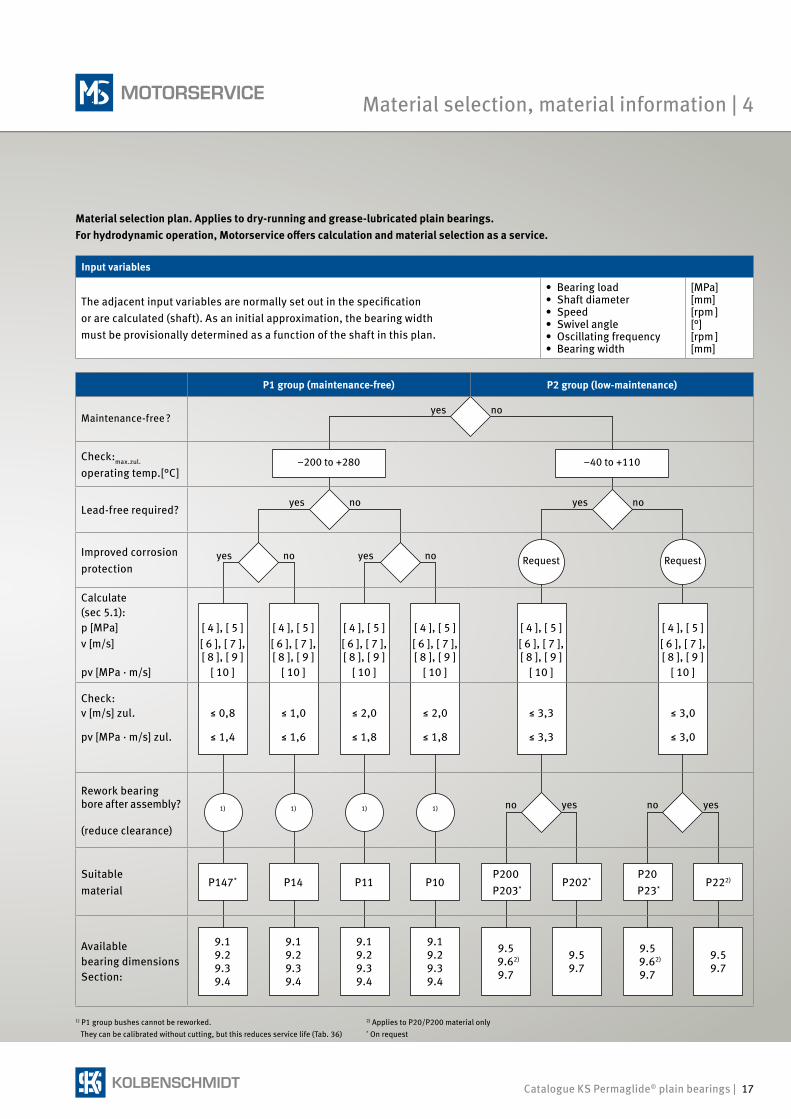
Material selection plan. Applies to dry-running and grease-lubricated plain bearings. For hydrodynamic operation, Motorservice offers calculation and material selection as a service.
Input variables
The adjacent input variables are normally set out in the specification or are calculated (shaft). As an initial approximation, the bearing width must be provisionally determined as a function of the shaft in this plan.
• Bearing load• Shaft diameter• Speed• Swivel angle• Oscillating frequency• Bearing width
[MPa][mm][rpm ][°][rpm ][mm]
1) P1 group bushes cannot be reworked. They can be calibrated without cutting, but this reduces service life (Tab. 36)
2) Applies to P20/P200 material only * On request
P1 group (maintenance-free) P2 group (low-maintenance)
Maintenance-free ?
yes
no
Check:max.zul.
operating temp.[°C]–200 to +280 –40 to +110
Lead-free required?
yes
no
yes
no
Improved corrosion protection
yes
no
yes
no Request Request
Calculate(sec 5.1):p [MPa]v [m/s]
pv [MPa · m/s]
[ 4 ], [ 5 ][ 6 ], [ 7 ],[ 8 ], [ 9 ]
[ 10 ]
[ 4 ], [ 5 ][ 6 ], [ 7 ],[ 8 ], [ 9 ]
[ 10 ]
[ 4 ], [ 5 ][ 6 ], [ 7 ],[ 8 ], [ 9 ]
[ 10 ]
[ 4 ], [ 5 ][ 6 ], [ 7 ],[ 8 ], [ 9 ]
[ 10 ]
[ 4 ], [ 5 ][ 6 ], [ 7 ],[ 8 ], [ 9 ]
[ 10 ]
[ 4 ], [ 5 ][ 6 ], [ 7 ],[ 8 ], [ 9 ]
[ 10 ]
Check:v [m/s] zul.
pv [MPa · m/s] zul.
≤ 0,8
≤ 1,4
≤ 1,0
≤ 1,6
≤ 2,0
≤ 1,8
≤ 2,0
≤ 1,8
≤ 3,3
≤ 3,3
≤ 3,0
≤ 3,0
Rework bearing bore after assembly? (reduce clearance)
1) 1) 1) 1)
no
yes
no
yes
Suitable material
P147* P14 P11 P10P200
P203*P202*
P20 P23*
P222)
Available bearing dimensionsSection:
9.19.29.39.4
9.19.29.39.4
9.19.29.39.4
9.19.29.39.4
9.5 9.62)
9.7
9.59.7
9.5 9.62)
9.7
9.59.7
Material selection, material information | 4
18 | Catalogue KS Permaglide® plain bearings
Brief descriptionP10 and P11 are sturdy, lead containing sliding materials with superior tribological performance. They are designed for main-tenance-free, dry-running applications, but can also be employed in systems with liquid lubric ation. The use of grease as a lubricant with P10, P11 is only possible to a limited extent, and is not recommended.
Material manufactureThe solid lubricant mass is produced in a specially adapted mixing process. In a parallel, continuous sintering operation, bronze powder is sintered onto the steel or bronze back as a sliding layer. This pro-duces a sliding layer with a thickness from 0.2 mm to 0.35 mm and a pore volume of approx. 30 %. Next, the cavities are filled with solid lubricant by means of impregnat-ing rollers. This process step is controlled in such a way that a running-in layer of solid lubricant up to a max. thickness of 0.03 mm is produced above the sliding layer. In further thermal treatments, the characteristic properties of the material system are adjusted, and the required thickness tolerances of the composite material are produced using controlled roller pairs.
Plain bearing productionSliding elements in a great variety of designs are produced from P10 and P11 in cutting, stamping and shaping processes. Standard designs are:• Cylindrical bushes• Collar bushes• Thrust washers• Strips
In a final step, plain bearings manufac-tured from P10 undergo anti-corrosion treatment on the bearing back, end faces and joint surfaces.Standard version: TinLayer thickness: approx. 0.002 mm
Additionally, P10 plain bearings can be supplied with improved corrosion- protection coating “Zinc, transparent passivated”, on request.P11 does not require any additional corrosion protection.
Important note:Tin is used as temporary corrosion
protection and an assembly aid.
Properties of P10• Very low stick-slip tendency• Low wear• Good chemical resistance• Low friction coefficient• No tendency to fuse with metal• Largely resistant to swelling• Does not absorb water
Preferred areas of application• Maintenance-free operation under
dry-running conditions• Rotating or oscillating movements
up to a speed of 2 m/s• Linear movements• Temperature range –200 °C to 280 °C
Properties of P11Material P11 is recommended for more stringent requirements in terms of corro-sion resistance or for use in aggressive media. It has some advantages over P10 in this respect:• Very good thermal conductivity and
therefore increased reliability• Anti-magnetic
Hydrodynamic operationUse in hydrodynamic conditions is possi-ble without problem up to a sliding speed of 3 m/s.In continuous operation above 3 m/s, there is a risk of flow erosion or cavitation.Motorservice offers the calculation of hydrodynamic operating states as a service.
4.1 P1 plain bearings
The materials P10 and P11 contain lead and must therefore not be used in applications involving food processing.
4 | Material selection, material information
4.1.1 P10, P11 … Sturdy and maintenance-free
Catalogue KS Permaglide® plain bearings | 19
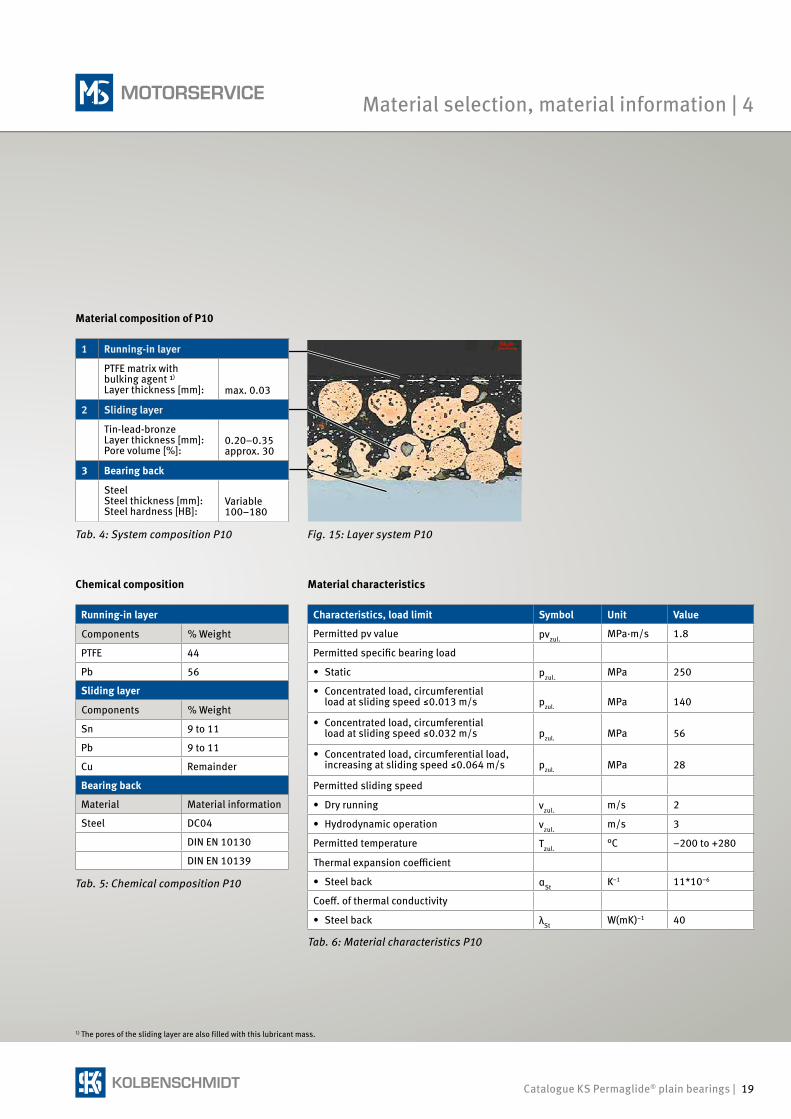
Material composition of P10
1 Running-in layer
PTFE matrix with bulking agent ¹)
Layer thickness [mm]: max. 0.03
2 Sliding layer
Tin-lead-bronzeLayer thickness [mm]:Pore volume [%]:
0.20–0.35approx. 30
3 Bearing back
SteelSteel thickness [mm]:Steel hardness [HB]:
Variable100–180
Tab. 4: System composition P10 Fig. 15: Layer system P10
Tab. 5: Chemical composition P10
Running-in layer
Components % Weight
PTFE 44
Pb 56
Sliding layer
Components % Weight
Sn 9 to 11
Pb 9 to 11
Cu Remainder
Bearing back
Material Material information
Steel DC04
DIN EN 10130
DIN EN 10139
Chemical composition
Characteristics, load limit Symbol Unit Value
Permitted pv value pvzul.MPa·m/s 1.8
Permitted specific bearing load
• Static pzul.MPa 250
• Concentrated load, circumferential load at sliding speed ≤0.013 m/s pzul. MPa 140
• Concentrated load, circumferential load at sliding speed ≤0.032 m/s pzul. MPa 56
• Concentrated load, circumferential load, increasing at sliding speed ≤0.064 m/s pzul. MPa 28
Permitted sliding speed
• Dry running vzul.m/s 2
• Hydrodynamic operation vzul.m/s 3
Permitted temperature Tzul.°C –200 to +280
Thermal expansion coefficient
• Steel back αStK–1 11*10–6
Coeff. of thermal conductivity
• Steel back λStW(mK)–1 40
Material characteristics
Tab. 6: Material characteristics P10
1) The pores of the sliding layer are also filled with this lubricant mass.
Material selection, material information | 4
20 | Catalogue KS Permaglide® plain bearings
Characteristics, load limit Symbol Unit Value
Permitted pv value pvzul. MPa * m/s 1,8
• Static p stat MPa 250
• Dynamic p dyn MPa 140
Speeds
• Dry running v rot [m/s] 2
• Hydrodynamic operation v lin [m/s] 3
Continuous operation temperature
• Min. Tmin °C –200
• Max. Tmax °C 280
Temporary Tshort °C 140
Thermal expansion coefficient a Bronze 10–5 1/K 1,7
Coefficient of thermal conductivity l Bronze W/m/K <=70
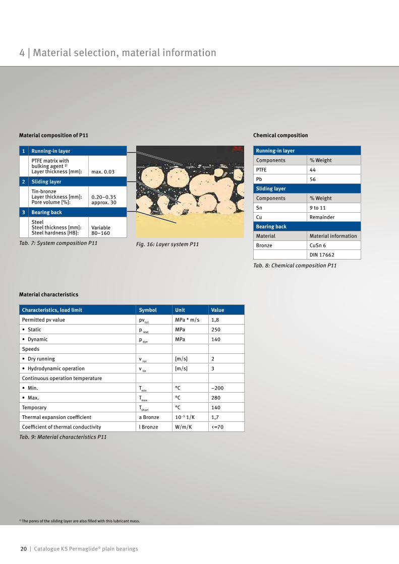
Material composition of P11
1 Running-in layer
PTFE matrix with bulking agent ¹)
Layer thickness [mm]: max. 0.03
2 Sliding layer
Tin-bronzeLayer thickness [mm]:Pore volume [%]:
0.20–0.35approx. 30
3 Bearing back
SteelSteel thickness [mm]:Steel hardness [HB]:
Variable80–160
Tab. 7: System composition P11 Fig. 16: Layer system P11
Tab. 8: Chemical composition P11
Running-in layer
Components % Weight
PTFE 44
Pb 56
Sliding layer
Components % Weight
Sn 9 to 11
Cu Remainder
Bearing back
Material Material information
Bronze CuSn 6
DIN 17662
Chemical composition
Material characteristics
Tab. 9: Material characteristics P11
1) The pores of the sliding layer are also filled with this lubricant mass.
4 | Material selection, material information
Catalogue KS Permaglide® plain bearings | 21
Brief descriptionP14 is a lead-free standard sliding mate-rial with a high tribological performance. It is designed for maintenance-free, dry-running applications. It may also be employed in systems with liquid lubrication, however.The use of grease as a lubricant with P14 is only possible to a limited extent, and is not recommended.
Material manufactureThe solid lubricant mass is produced in a specially adapted mixing process.In a parallel, continuous sintering opera-tion, bronze powder is sintered onto the steel back as a sliding layer. This produces a sliding layer with a thickness from 0.2 mm to 0.35 mm and a pore volume of approx. 30 %. Next, the cavities are filled with solid lubricant by means of impregnating rollers. This process step is controlled in such a way that a running-in layer of solid lubricant up to a max. thick-ness of 0.03 mm is produced above the sliding layer. In further thermal treat-ments, the characteristic properties of the material system are adjusted, and the required thickness tolerances of the com-posite material produced using controlled roller pairs.
Plain bearing productionSliding elements in a great variety of designs are produced from P14 in cutting, stamping and shaping processes. Standard designs are: • Cylindrical bushes• Collar bushes• Thrust washers• Strips
In a final step, plain bearings manufac-tured from P14 undergo anti-corrosion treatment on the bearing back, end faces and joint surfaces.Standard version: TinLayer thickness: approx. 0.002 mm
Properties of P14• Lead-free• Very low stick-slip tendency• Low wear• Low friction coefficient• No tendency to fuse with metal• Very low tendency to swell
Preferred areas of application• Maintenance-free operation in dry-
running conditions where lead-free parts are required
• Rotating or oscillating movements up to a speed of 1 m/s
• Linear movements• Temperature range –200 °C to 280 °C
Hydrodynamic operationUse in hydrodynamic conditions is possi-ble without problem up to a sliding speed of 3 m/s.In continuous operation above 3 m/s, there is a risk of flow erosion or cavitation.Motorservice offers the calculation of hydrodynamic operating states as a service.
Important note:Tin is used as temporary corrosion
protection and an assembly aid.
P14 cannot be used in water(Alternative: P10, P11, P147)
4.1.2 P14 … Maintenance-free and environmentally friendly
Material selection, material information | 4
22 | Catalogue KS Permaglide® plain bearings
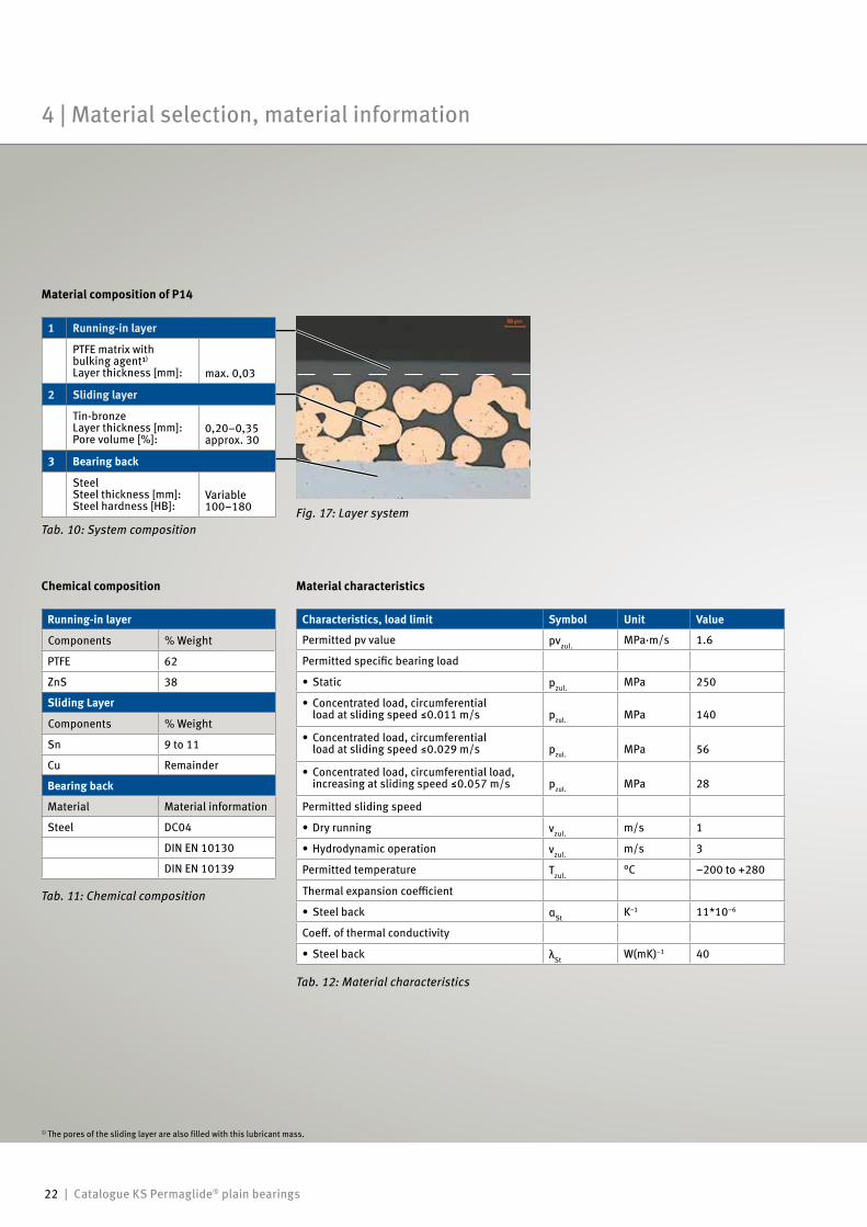
Material composition of P14
Tab. 12: Material characteristics
Characteristics, load limit Symbol Unit Value
Permitted pv value pvzul.MPa·m/s 1.6
Permitted specific bearing load
• Static pzul.MPa 250
• Concentrated load, circumferential load at sliding speed ≤0.011 m/s pzul. MPa 140
• Concentrated load, circumferential load at sliding speed ≤0.029 m/s pzul. MPa 56
• Concentrated load, circumferential load, increasing at sliding speed ≤0.057 m/s pzul. MPa 28
Permitted sliding speed
• Dry running vzul.m/s 1
• Hydrodynamic operation vzul.m/s 3
Permitted temperature Tzul.°C –200 to +280
Thermal expansion coefficient
• Steel back αStK–1 11*10–6
Coeff. of thermal conductivity
• Steel back λStW(mK)–1 40
Material characteristics
Fig. 17: Layer system
Tab. 11: Chemical composition
Running-in layer
Components % Weight
PTFE 62
ZnS 38
Sliding Layer
Components % Weight
Sn 9 to 11
Cu Remainder
Bearing back
Material Material information
Steel DC04
DIN EN 10130
DIN EN 10139
Chemical composition
Tab. 10: System composition
1 Running-in layer
PTFE matrix with bulking agent¹)
Layer thickness [mm]: max. 0,03
2 Sliding layer
Tin-bronzeLayer thickness [mm]:Pore volume [%]:
0,20–0,35approx. 30
3 Bearing back
SteelSteel thickness [mm]:Steel hardness [HB]:
Variable100–180
1) The pores of the sliding layer are also filled with this lubricant mass.
4 | Material selection, material information
Catalogue KS Permaglide® plain bearings | 23
Brief descriptionP147 is a lead-free special sliding material with a high tribological performance. It is designed for maintenance-free, dry-running applications, particularly in areas subject to increased corrosion. It may also be used in systems with liquid lubrication. The use of grease as a lubri-cant with P147 is only possible to a limited extent, and is not recommended.
Material manufactureThe solid lubricant mass is produced in a specially adapted mixing process.In a parallel, continuous sintering opera-tion, bronze powder is sintered onto the steel back as a sliding layer. This produces a sliding layer with a thickness from 0.2 mm to 0.35 mm and a pore volume of approx. 30 %. Next, the cavities are filled with solid lubricant by means of impregnating rollers. This process step is controlled in such a way that a running-in layer of solid lubricant up to a max. thick-ness of 0.03 mm is produced above the sliding layer. In further thermal treat-ments, the characteristic properties of the material system are adjusted, and the required thickness tolerances of the com-posite material produced using controlled roller pairs.
Plain bearing productionSliding elements in a great variety of designs are produced from P147 in cut-ting, stamping and shaping processes. Standard designs are:• Cylindrical bushes• Collar bushes• Thrust washers• Strips In a final step, plain bearings manufac-tured from P147 undergo special anti- corrosion treatment on the bearing back, end faces and joint surfaces.Standard version: tinLayer thickness: approx. 0.002 mm• Higher corrosion protection require-
ments (on request). Version: Zinc, transparent passivated Layer thickness: 0.008 mm to 0.012 mm Greater layer thickness is available on request.
Properties of P147• Lead-free• Very low stick-slip tendency• Low wear• Good chemical resistance• Low friction coefficient• No tendency to fuse with metal• Very low tendency to swell• Does not absorb water• Very good corrosion resistance
Preferred areas of application• In aggressive media¹)
• Outside machines and systems¹)
• Maintenance-free operation in dry- running conditions where lead-free parts are required
• Rotating or oscillating movements up to a speed of 0.8 m/s
• Linear movements• Temperature range –200 °C to 280 °C
Hydrodynamic operationUse in hydrodynamic conditions is possi-ble without problem up to a sliding speed of 3 m/s.In continuous operation above 3 m/s, there is a risk of flow erosion or cavitation.Motorservice offers the calculation of hydrodynamic operating states as a service.
1) P147 satisfies the requirements of the salt spray test to DIN 50021
4.1.2 P147 … Maintenance-free and corrosion-resistant
Important note:Transparent passivated zinc is an
especially effective anti-corrosion agent. An inclined position of the bush must be avoided during installation (force-fitting) of the bearing bushes. As this carries a risk of damaging the zinc coating.
Important note:The material P147 is available on
request.
Material selection, material information | 4
24 | Catalogue KS Permaglide® plain bearings
Characteristics, load limit Symbol Unit Value
Permitted pv value pvzul.MPa·m/s 1,4
Permitted specific bearing load
• Static pzul.MPa 250
• Concentrated load, circumferential load at sliding speed ≤0.010 m/s pzul. MPa 140
• Concentrated load, circumferential load at sliding speed ≤0.025 m/s pzul. MPa 56
• Concentrated load, circumferential load, increasing at sliding speed ≤0.050 m/s pzul. MPa 28
Permitted sliding speed
• Dry running vzul.m/s 0.8
Permitted temperature Tzul.°C –200 to +280
Thermal expansion coefficient
• Steel back αStK–1 11*10–6
Coeff. of thermal conductivity
• Steel back λStW(mK)–1 40
Material characteristics
Tab. 15: Material characteristics
Tab. 14: Chemical composition
Running-in layer
Components % Weight
PTFE 82
BaSO4 18
Sliding layer
Components % Weight
Sn 9 to 11
Cu Remainder
Material Material information
Steel DC04
DIN EN 10130
DIN EN 10139
Chemical composition
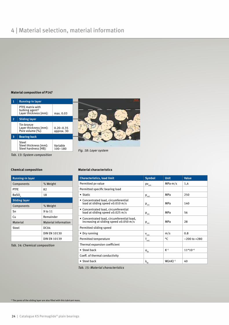
Fig. 18: Layer system
Material composition of P147
Tab. 13: System composition
1 Running-in layer
PTFE matrix with bulking agent¹)
Layer thickness [mm]: max. 0.03
2 Sliding layer
Tin-bronzeLayer thickness [mm]:Pore volume [%]:
0.20–0.35approx. 30
3 Bearing back
SteelSteel thickness [mm]:Steel hardness [HB]:
Variable100–180
1) The pores of the sliding layer are also filled with this lubricant mass.
4 | Material selection, material information
Catalogue KS Permaglide® plain bearings | 25
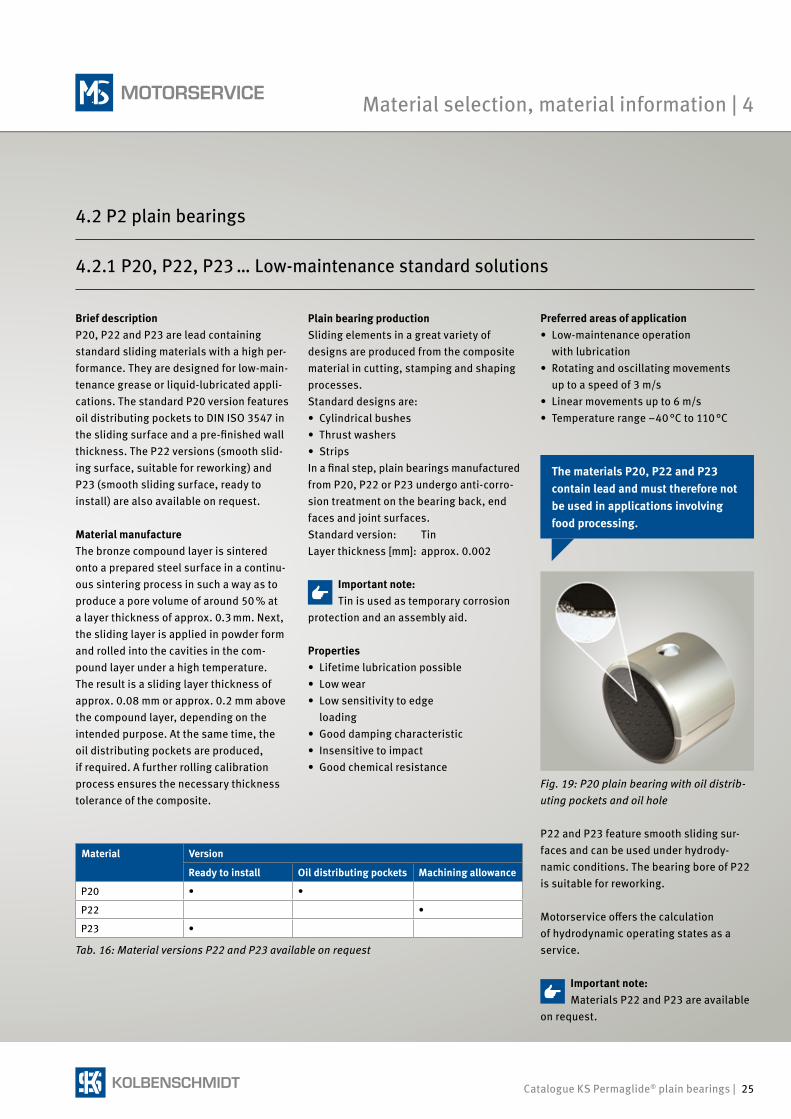
Brief descriptionP20, P22 and P23 are lead containing standard sliding materials with a high per-formance. They are designed for low-main-tenance grease or liquid-lubricated appli-cations. The standard P20 version features oil distributing pockets to DIN ISO 3547 in the sliding surface and a pre-finished wall thickness. The P22 versions (smooth slid-ing surface, suitable for reworking) and P23 (smooth sliding surface, ready to install) are also available on request.
Material manufactureThe bronze compound layer is sintered onto a prepared steel surface in a continu-ous sintering process in such a way as to produce a pore volume of around 50 % at a layer thickness of approx. 0.3 mm. Next, the sliding layer is applied in powder form and rolled into the cavities in the com-pound layer under a high temperature. The result is a sliding layer thickness of approx. 0.08 mm or approx. 0.2 mm above the compound layer, depending on the intended purpose. At the same time, the oil distributing pockets are produced, if required. A further rolling calibration process ensures the necessary thickness tolerance of the composite.
Plain bearing productionSliding elements in a great variety of designs are produced from the composite material in cutting, stamping and shaping processes.Standard designs are:• Cylindrical bushes• Thrust washers• StripsIn a final step, plain bearings manufactured from P20, P22 or P23 undergo anti-corro-sion treatment on the bearing back, end faces and joint surfaces.Standard version: TinLayer thickness [mm]: approx. 0.002
Preferred areas of application • Low-maintenance operation
with lubrication• Rotating and oscillating movements
up to a speed of 3 m/s• Linear movements up to 6 m/s• Temperature range –40 °C to 110 °C
Tab. 16: Material versions P22 and P23 available on request
Material Version
Ready to install Oil distributing pockets Machining allowance
P20 • •
P22 •
P23 •
Properties• Lifetime lubrication possible• Low wear • Low sensitivity to edge
loading• Good damping characteristic• Insensitive to impact• Good chemical resistance
P22 and P23 feature smooth sliding sur-faces and can be used under hydrody-namic conditions. The bearing bore of P22 is suitable for reworking.
Motorservice offers the calculation of hydrodynamic operating states as a service.
Fig. 19: P20 plain bearing with oil distrib-uting pockets and oil hole
4.2.1 P20, P22, P23 … Low-maintenance standard solutions
Important note:Tin is used as temporary corrosion
protection and an assembly aid.
The materials P20, P22 and P23 contain lead and must therefore not be used in applications involving food processing.
Important note:Materials P22 and P23 are available
on request.
Material selection, material information | 4
4.2 P2 plain bearings
26 | Catalogue KS Permaglide® plain bearings
Tab. 19: Material characteristics
Characteristics, load limit Symbol Unit Value
Permitted pv value pvzul.MPa·m/s 3
Permitted specific bearing load
• Static pzul.MPa 250
• Concentrated load, circumferential load at sliding speed ≤0.021 m/s pzul. MPa 140
• Concentrated load, circumferential load at sliding speed ≤0.043 m/s pzul. MPa 70
• Concentrated load, circumferential load, increasing at sliding speed ≤0.086 m/s pzul. MPa 35
Permitted sliding speed
• Grease-lubricated, rotating, oscillating vzul.m/s 3
• Grease-lubricated, linear vzul.m/s 6
• Hydrodynamic operation vzul.m/s 6
Permitted temperature Tzul.°C –40 to +110
Thermal expansion coefficient
• Steel back αStK–1 11*10–6
Coeff. of thermal conductivity
• Steel back λStW(mK)–1 40
Material characteristics
Tab. 18: Chemical composition
Sliding layer
Components % Weight
PVDF 51
PTFE 8
Pb 41
Intermediate layer
Components % Weight
Sn 9 to 11
Cu Remainder
Bearing back
Material Material information
Steel DC04
DIN EN 10130
DIN EN 10139
Chemical composition
1) The cavities of the intermediate sliding layer are also filled with this mass.
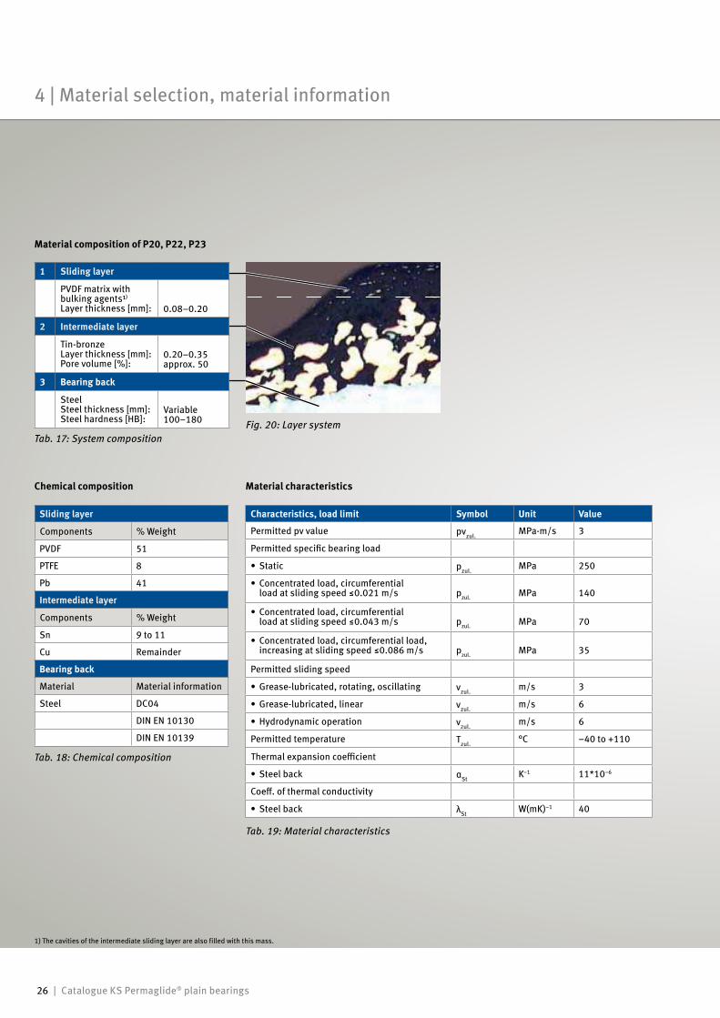
Fig. 20: Layer system
Material composition of P20, P22, P23
Tab. 17: System composition
1 Sliding layer
PVDF matrix with bulking agents¹)
Layer thickness [mm]: 0.08–0.20
2 Intermediate layer
Tin-bronzeLayer thickness [mm]:Pore volume [%]:
0.20–0.35approx. 50
3 Bearing back
SteelSteel thickness [mm]:Steel hardness [HB]:
Variable100–180
4 | Material selection, material information
Catalogue KS Permaglide® plain bearings | 27
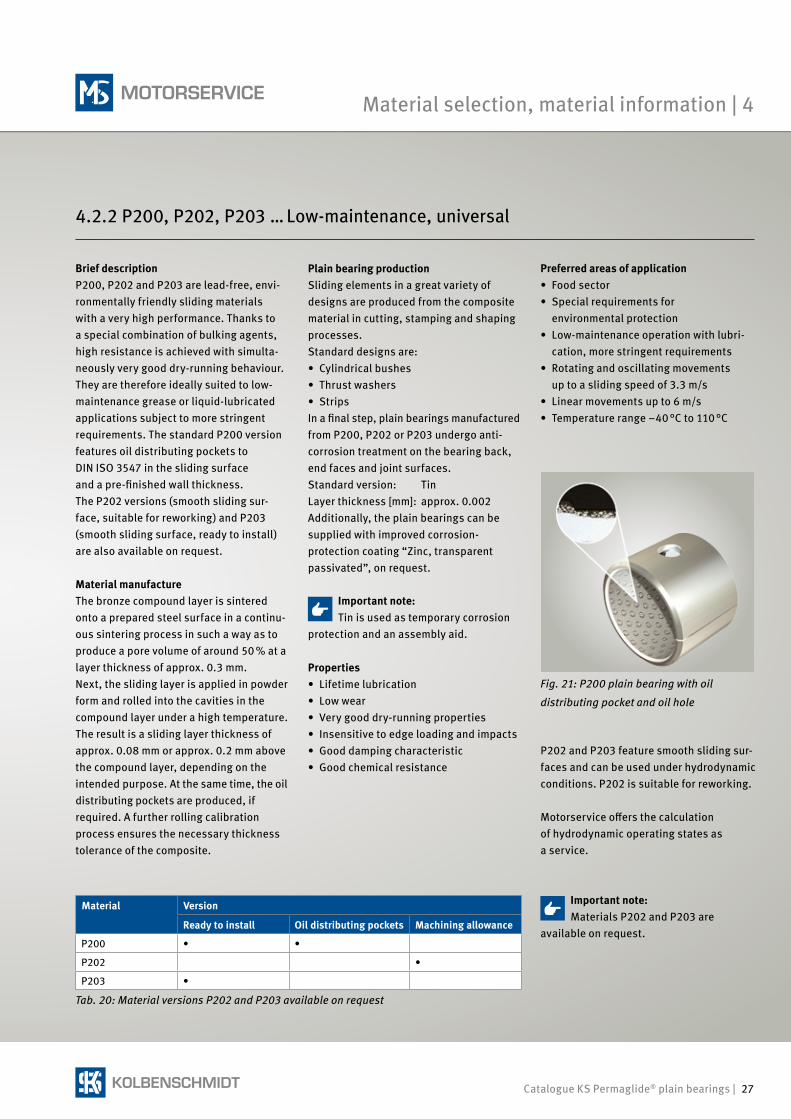
Brief descriptionP200, P202 and P203 are lead-free, envi-ronmentally friendly sliding materials with a very high performance. Thanks to a special combination of bulking agents, high resistance is achieved with simulta-neously very good dry-running behaviour. They are therefore ideally suited to low- maintenance grease or liquid-lubricated applications subject to more stringent requirements. The standard P200 version features oil distributing pockets to DIN ISO 3547 in the sliding surface and a pre-finished wall thickness.The P202 versions (smooth sliding sur-face, suitable for reworking) and P203 (smooth sliding surface, ready to install) are also available on request.
Material manufactureThe bronze compound layer is sintered onto a prepared steel surface in a continu-ous sintering process in such a way as to produce a pore volume of around 50 % at a layer thickness of approx. 0.3 mm. Next, the sliding layer is applied in powder form and rolled into the cavities in the compound layer under a high temperature. The result is a sliding layer thickness of approx. 0.08 mm or approx. 0.2 mm above the compound layer, depending on the intended purpose. At the same time, the oil distributing pockets are produced, if required. A further rolling calibration process ensures the necessary thickness tolerance of the composite.
Plain bearing productionSliding elements in a great variety of designs are produced from the composite material in cutting, stamping and shaping processes.Standard designs are:• Cylindrical bushes• Thrust washers• StripsIn a final step, plain bearings manufactured from P200, P202 or P203 undergo anti- corrosion treatment on the bearing back, end faces and joint surfaces.Standard version: TinLayer thickness [mm]: approx. 0.002Additionally, the plain bearings can be supplied with improved corrosion- protection coating “Zinc, transparent passivated”, on request.
Tab. 20: Material versions P202 and P203 available on request
Properties• Lifetime lubrication• Low wear • Very good dry-running properties• Insensitive to edge loading and impacts• Good damping characteristic• Good chemical resistance
Material Version
Ready to install Oil distributing pockets Machining allowance
P200 • •
P202 •
P203 •
Preferred areas of application• Food sector• Special requirements for
environmental protection• Low-maintenance operation with lubri-
cation, more stringent requirements• Rotating and oscillating movements
up to a sliding speed of 3.3 m/s• Linear movements up to 6 m/s• Temperature range –40 °C to 110 °C
P202 and P203 feature smooth sliding sur-faces and can be used under hydro dynamic conditions. P202 is suitable for reworking.
Motorservice offers the calculation of hydrodynamic operating states as a service.
Fig. 21: P200 plain bearing with oil
distributing pocket and oil hole
4.2.2 P200, P202, P203 … Low-maintenance, universal
Important note:Tin is used as temporary corrosion
protection and an assembly aid.
Important note:Materials P202 and P203 are
available on request.
Material selection, material information | 4
28 | Catalogue KS Permaglide® plain bearings
Tab. 23: Material characteristics
Characteristics, load limit Symbol Unit Value
Permitted pv value pvzul.MPa·m/s 3.3
Permitted specific bearing load
• Static pzul.MPa 250
• Concentrated load, circumferential load at sliding speed ≤0.024 m/s pzul. MPa 140
• Concentrated load, circumferential load at sliding speed ≤0.047 m/s pzul. MPa 70
• Concentrated load, circumferential load, increasing at sliding speed ≤0.094 m/s pzul. MPa 35
Permitted sliding speed
• Grease-lubricated, rotating, oscillating vzul.m/s 3.3
• Grease-lubricated, linear vzul.m/s 6
• Hydrodynamic operation vzul.m/s 6
Permitted temperature Tzul.°C –40 to +110
Permitted temperature
• Steel back αStK–1 11*10–6
• Steel back
• Steel back λStW(mK)–1 40
Material characteristics
Sliding layer
Components % Weight
PTFE 9 to 12
Wear and friction- reducing bulking agents
22 to 26
PVDF Rest
Intermediate layer
Components % Weight
Sn 9 to 11
P max. 0.05
Other max. 0.05
Cu Remainder
Bearing back
Material Material information
Steel DC04
DIN EN 10130
DIN EN 10139
Tab. 22: Chemical composition
Chemical composition
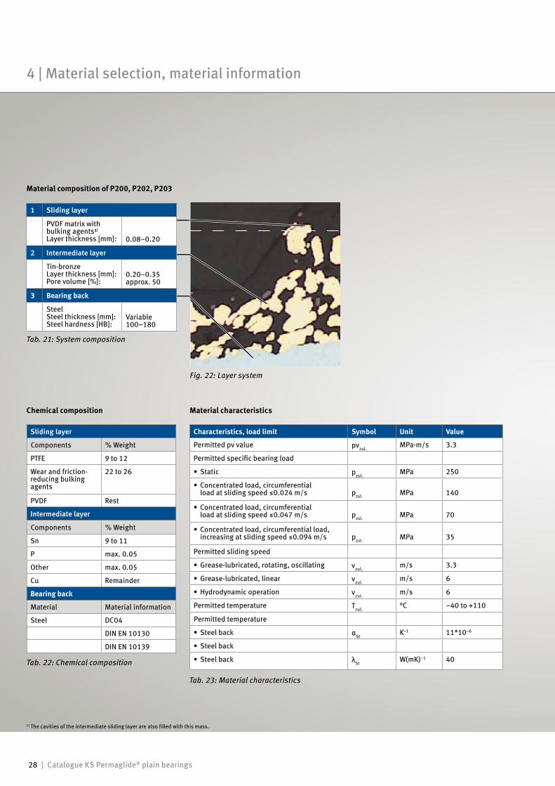
Fig. 22: Layer system
Material composition of P200, P202, P203
Tab. 21: System composition
1 Sliding layer
PVDF matrix with bulking agents¹)
Layer thickness [mm]: 0.08–0.20
2 Intermediate layer
Tin-bronzeLayer thickness [mm]:Pore volume [%]:
0.20–0.35approx. 50
3 Bearing back
SteelSteel thickness [mm]:Steel hardness [HB]:
Variable100–180
1) The cavities of the intermediate sliding layer are also filled with this mass.
4 | Material selection, material information
Catalogue KS Permaglide® plain bearings | 29
Nominal service life calculation | 5
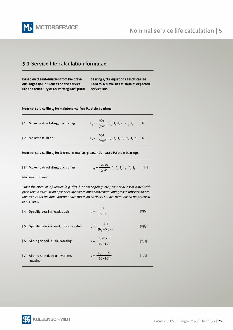
Based on the information from the previ-ous pages the influences on the service life and reliability of KS Permaglide® plain
[ 1 ] Movement: rotating, oscillating LN =400
fA · fp · fv · fT · fw · fR [ h ](pv)1,2
v =Do · Π · n
[m/s]60 · 103
v =Di · Π · n
[m/s]60 · 103
p =4 ·F
[MPa](Do
2–Di2) · π
p =F
[MPa]Di · B
LN =2000
fA · fp · fv · fT · fw · fR [ h ](pv)1,5
Since the effect of influences (e.g. dirt, lubricant ageing, etc.) cannot be ascertained with precision, a calculation of service life where linear movement and grease lubrication are involved is not feasible. Motorservice offers an advisory service here, based on practical experience.
LN =400
fA · fp · fv · fT · fw · fR · fL [ h ](pv)1,2
[ 7 ] Sliding speed, thrust washer, rotating
[ 6 ] Sliding speed, bush, rotating
[ 2 ] Movement: linear
[ 3 ] Movement: rotating, oscillating
[ 5 ] Specific bearing load, thrust washer
[ 4 ] Specific bearing load, bush
Movement: linear
5.1 Service life calculation formulae
Nominal service life LN for maintenance-free P1 plain bearings
Nominal service life LN for low-maintenance, grease-lubricated P2 plain bearings
bearings, the equations below can be used to achieve an estimate of expected service life.
30 | Catalogue KS Permaglide® plain bearings
φ
AB
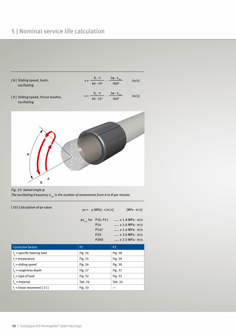
[ 8 ] Sliding speed, bush, oscillating
v =Di · π ·
2φ · nosz [m/s]60 · 103 360°
Fig. 23: Swivel angle φThe oscillating frequency nosz is the number of movements from A to B per minute.
Correction factors P1 P2
fp = specific bearing load Fig. 24 Fig. 28
ft = temperature Fig. 25 Fig. 29
fv = sliding speed Fig. 26 Fig. 30
fR = roughness depth Fig. 27 Fig. 31
fA = type of load Fig. 32 Fig. 32
fw = material Tab. 24 Tab. 24
fL = linear movement [ 11 ] Fig. 33 ---
pv = p [MPa] · v [m/s] [MPa · m/s]
pvzul. for P10, P11 ….. ≤ 1.8 MPa · m/s P14 ….. ≤ 1.6 MPa · m/s P147 ….. ≤ 1.4 MPa · m/s P20 ….. ≤ 3.0 MPa · m/s P200 ….. ≤ 3.3 MPa · m/s
[ 10 ] Calculation of pv value
[ 9 ] Sliding speed, thrust washer, oscillating
v =Do · π
·2φ · nosz [m/s]
60 · 103 360°
5 | Nominal service life calculation
Catalogue KS Permaglide® plain bearings | 31
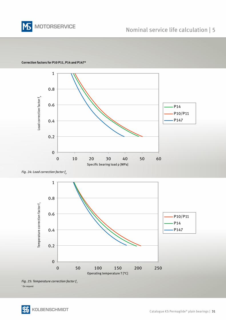
Load
cor
rect
ion
fact
or f p
Specific bearing load p [MPa]
Tem
pera
ture
cor
rect
ion
fact
or f T
Operating temperature T [°C]
Fig. 24: Load correction factor fp
Fig. 25: Temperature correction factor fT* On request
Correction factors for P10 P11, P14 and P147*
Nominal service life calculation | 5
32 | Catalogue KS Permaglide® plain bearings
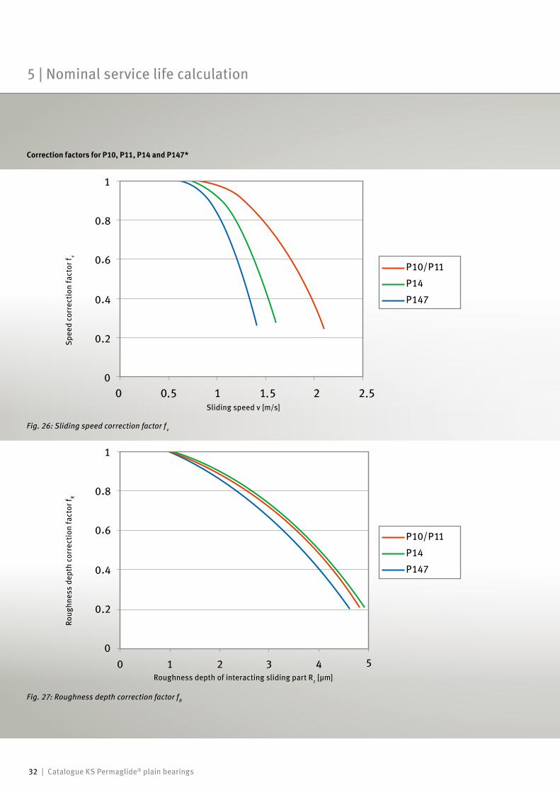
Fig. 27: Roughness depth correction factor fR
Sliding speed v [m/s]
Spee
d co
rrec
tion
fact
or f v
Roughness depth of interacting sliding part Rz [µm]
Roug
hnes
s de
pth
corr
ectio
n fa
ctor
f R
Fig. 26: Sliding speed correction factor fv
Correction factors for P10, P11, P14 and P147*
5 | Nominal service life calculation
Catalogue KS Permaglide® plain bearings | 33
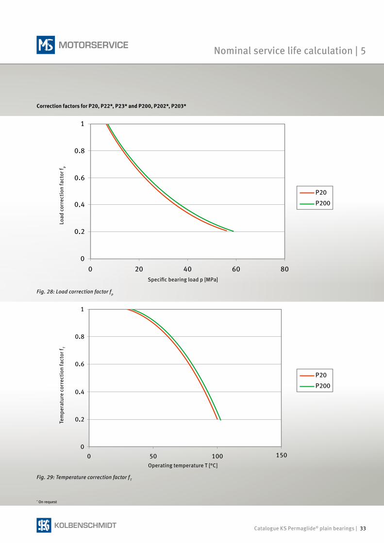
Tem
pera
ture
cor
rect
ion
fact
or f T
Operating temperature T [°C]
Load
cor
rect
ion
fact
or f p
Specific bearing load p [MPa]
Fig. 29: Temperature correction factor fT
Fig. 28: Load correction factor fp
Correction factors for P20, P22*, P23* and P200, P202*, P203*
* On request
Nominal service life calculation | 5
34 | Catalogue KS Permaglide® plain bearings
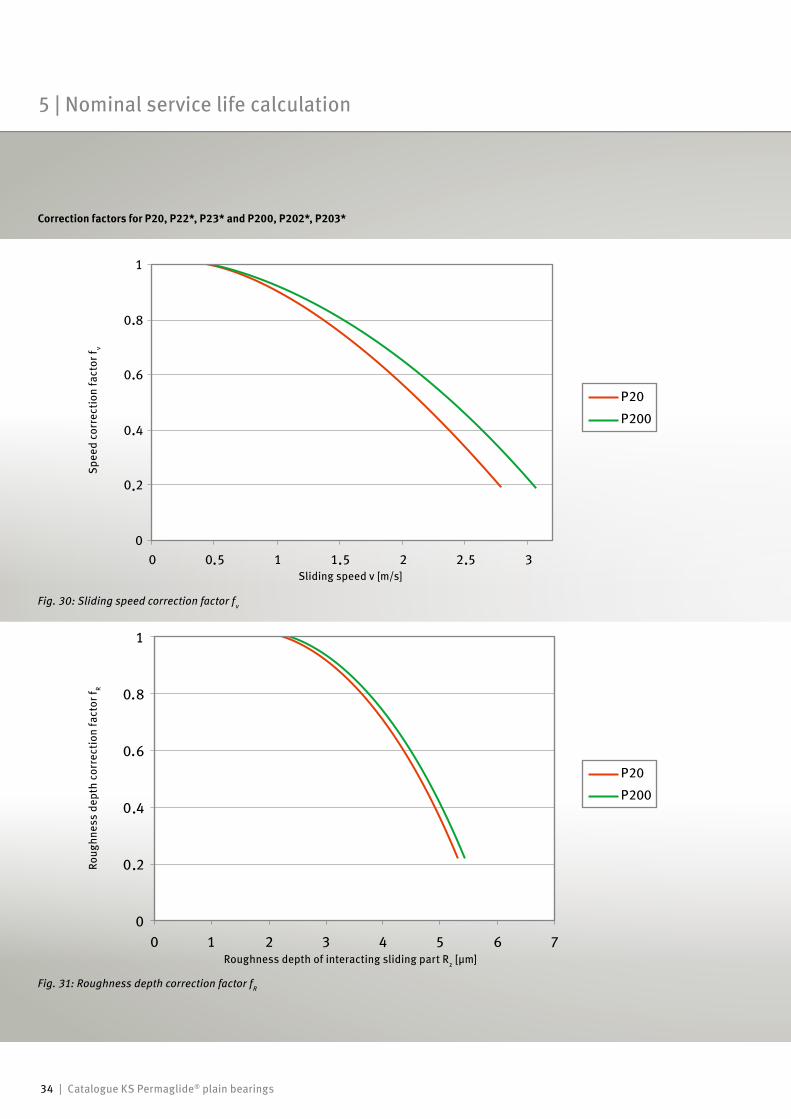
Fig. 30: Sliding speed correction factor fv
Spee
d co
rrec
tion
fact
or f v
Roug
hnes
s de
pth
corr
ectio
n fa
ctor
f R
Roughness depth of interacting sliding part Rz [µm]
Fig. 31: Roughness depth correction factor fR
Sliding speed v [m/s]
Correction factors for P20, P22*, P23* and P200, P202*, P203*
5 | Nominal service life calculation
Catalogue KS Permaglide® plain bearings | 35
Hmax= 2,5 x B
B
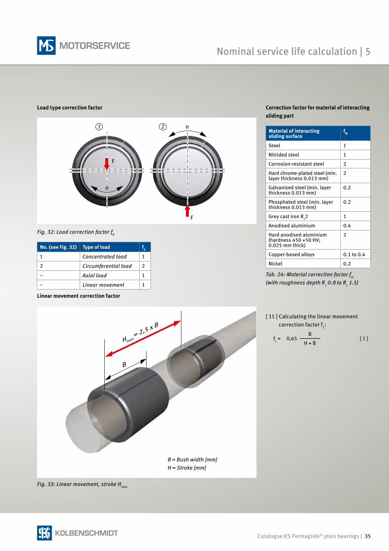
Correction factor for material of interacting sliding part
Load type correction factor
Fig. 33: Linear movement, stroke Hmax.
Linear movement correction factor
No. (see Fig. 32) Type of load fA
1 Concentrated load 1
2 Circumferential load 2
– Axial load 1
– Linear movement 1
Fig. 32: Load correction factor fA
[ 11 ] Calculating the linear movement correction factor fL:
fL = 0,65B
[ 1 ] H + B
Tab. 24: Material correction factor fw (with roughness depth Rz 0.8 to Rz 1.5)
Material of interacting sliding surface
fW
Steel 1
Nitrided steel 1
Corrosion-resistant steel 2
Hard chrome-plated steel (min. layer thickness 0.013 mm)
2
Galvanised steel (min. layer thickness 0.013 mm)
0.2
Phosphated steel (min. layer thickness 0.013 mm)
0.2
Grey cast iron Rz2 1
Anodised aluminium 0.4
Hard anodised aluminium(hardness 450 +50 HV; 0.025 mm thick)
2
Copper-based alloys 0.1 to 0.4
Nickel 0.2
1 2
F
F
n
n
B = Bush width [mm]H = Stroke [mm]
Nominal service life calculation | 5
36 | Catalogue KS Permaglide® plain bearings
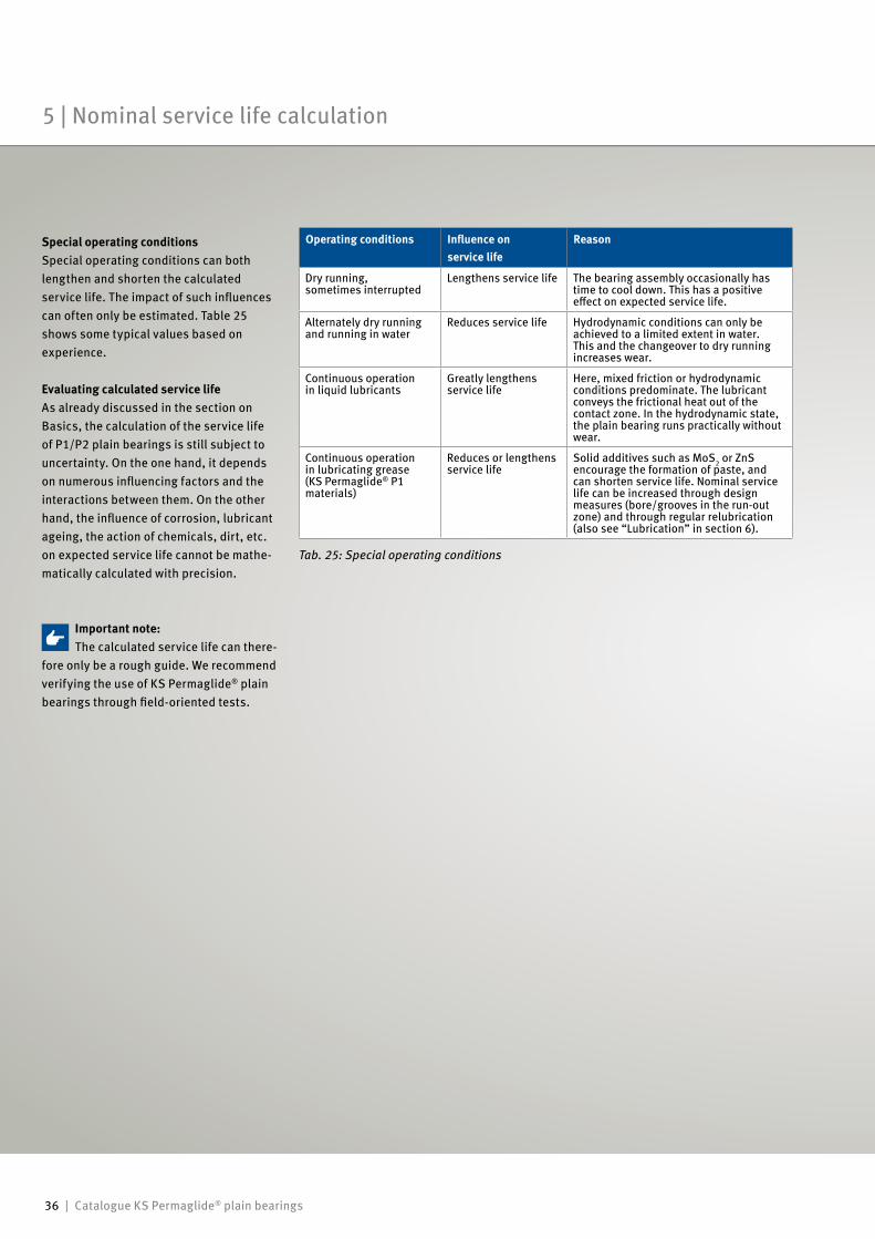
Operating conditions Influence on service life
Reason
Dry running, sometimes interrupted
Lengthens service life The bearing assembly occasionally has time to cool down. This has a positive effect on expected service life.
Alternately dry running and running in water
Reduces service life Hydrodynamic conditions can only be achieved to a limited extent in water. This and the changeover to dry running increases wear.
Continuous operation in liquid lubricants
Greatly lengthens service life
Here, mixed friction or hydrodynamic conditions predominate. The lubricant conveys the frictional heat out of the contact zone. In the hydrodynamic state, the plain bearing runs practically without wear.
Continuous operation in lubricating grease(KS Permaglide® P1 materials)
Reduces or lengthens service life
Solid additives such as MoS2 or ZnS encourage the formation of paste, and can shorten service life. Nominal service life can be increased through design measures (bore/grooves in the run-out zone) and through regular relubrication (also see “Lubrication” in section 6).
Special operating conditionsSpecial operating conditions can both lengthen and shorten the calculated service life. The impact of such influences can often only be estimated. Table 25 shows some typical values based on experience.
Evaluating calculated service lifeAs already discussed in the section on Basics, the calculation of the service life of P1/P2 plain bearings is still subject to uncertainty. On the one hand, it depends on numerous influencing factors and the interactions between them. On the other hand, the influence of corrosion, lubricant ageing, the action of chemicals, dirt, etc. on expected service life cannot be mathe-matically calculated with precision.
Tab. 25: Special operating conditions
Important note:The calculated service life can there-
fore only be a rough guide. We recommend verifying the use of KS Permaglide® plain bearings through field-oriented tests.
5 | Nominal service life calculation
Catalogue KS Permaglide® plain bearings | 37
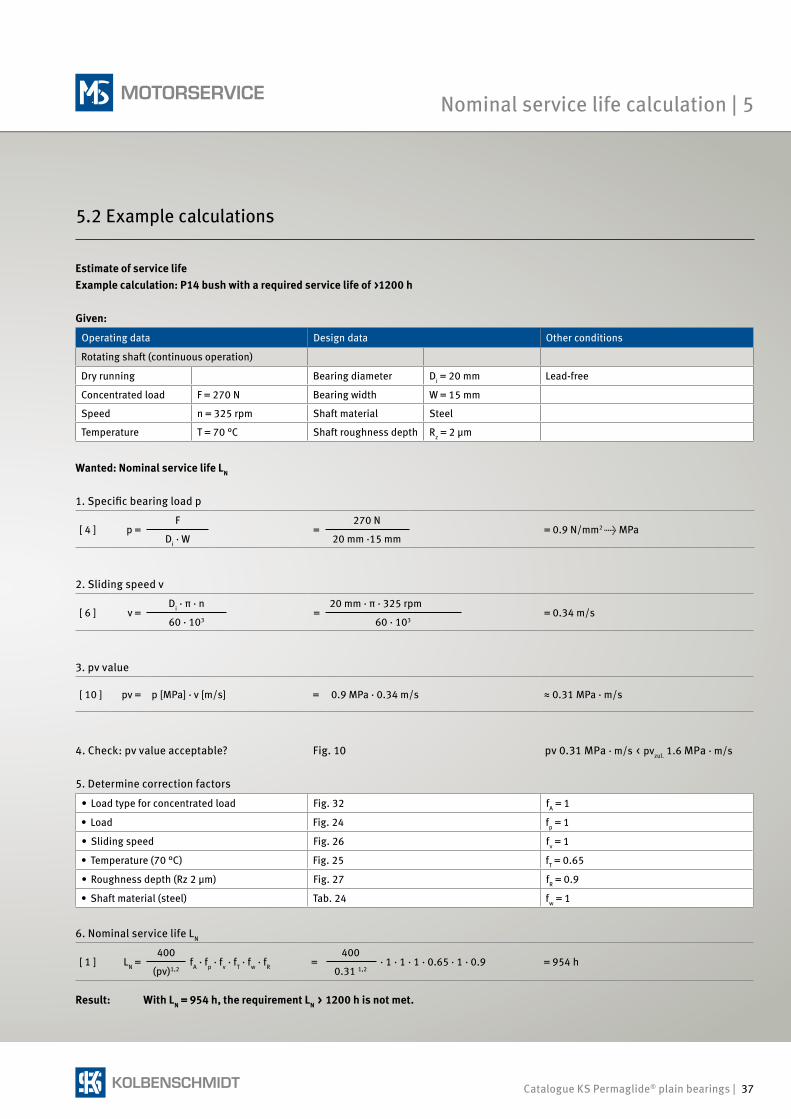
Given:
Operating data Design data Other conditions
Rotating shaft (continuous operation)
Dry running Bearing diameter Di = 20 mm Lead-free
Concentrated load F = 270 N Bearing width W = 15 mm
Speed n = 325 rpm Shaft material Steel
Temperature T = 70 °C Shaft roughness depth Rz = 2 μm
Wanted: Nominal service life LN
1. Specific bearing load p
[ 4 ] p =F
=270 N
= 0.9 N/mm2 → MPaDi · W 20 mm ·15 mm
2. Sliding speed v
[ 6 ] v =Di · π · n
=20 mm · π · 325 rpm
= 0.34 m/s60 · 103 60 · 103
3. pv value
[ 10 ] pv = p [MPa] · v [m/s] = 0.9 MPa · 0.34 m/s ≈ 0.31 MPa · m/s
4. Check: pv value acceptable? Fig. 10 pv 0.31 MPa · m/s < pvzul. 1.6 MPa · m/s
5. Determine correction factors
• Load type for concentrated load Fig. 32 fA = 1
• Load Fig. 24 fp = 1
• Sliding speed Fig. 26 fv = 1
• Temperature (70 °C) Fig. 25 fT = 0.65
• Roughness depth (Rz 2 µm) Fig. 27 fR = 0.9
• Shaft material (steel) Tab. 24 fw = 1
6. Nominal service life LN
[ 1 ] LN =400
fA · fp · fv · fT · fw · fR =400
· 1 · 1 · 1 · 0.65 · 1 · 0.9 = 954 h(pv)1,2 0.31 1,2
Result: With LN = 954 h, the requirement LN > 1200 h is not met.
Estimate of service lifeExample calculation: P14 bush with a required service life of >1200 h
5.2 Example calculations
Nominal service life calculation | 5
38 | Catalogue KS Permaglide® plain bearings
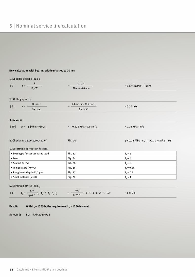
New calculation with bearing width enlarged to 20 mm 1. Specific bearing load p
[ 4 ] p =F
=270 N
= 0.675 N/mm2 → MPaDi · W 20 mm ·20 mm
2. Sliding speed v
[ 6 ] v =Di · π · n
=20mm · π · 325 rpm
= 0.34 m/s60 · 103 60 · 103
3. pv value
[ 10 ] pv = p [MPa] · v [m/s] = 0.675 MPa · 0.34 m/s ≈ 0.23 MPa · m/s
4. Check: pv value acceptable? Fig. 10 pv 0.23 MPa · m/s < pvzul. 1.6 MPa · m/s
5. Determine correction factors
• Load type for concentrated load Fig. 32 fA = 1
• Load Fig. 24 fp = 1
• Sliding speed Fig. 26 fv = 1
• Temperature (70 °C) Fig. 25 fT = 0.65
• Roughness depth (Rz 2 µm) Fig. 27 fR = 0.9
• Shaft material (steel) Fig. 22 fw = 1
6. Nominal service life LN
[ 1 ] LN =400
fA · fp · fv · fT · fw · fR =400
· 1 · 1 · 1 · 0,65 · 1 · 0.9 = 1365 h(pv)1,2 0.23 1,2
Result: With LN = 1365 h, the requirement LN > 1200 h is met.
Selected: Bush PAP 2020 P14
5 | Nominal service life calculation
Catalogue KS Permaglide® plain bearings | 39
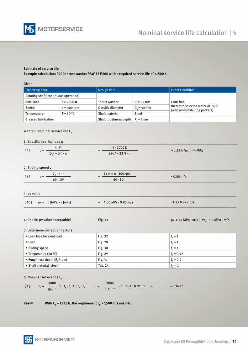
Estimate of service life Example calculation: P200 thrust washer PAW 32 P200 with a required service life of >1500 h
Given:
Operating data Design data Other conditions
Rotating shaft (continuous operation)
Axial load F = 2000 N Thrust washer Di = 32 mm Lead-free,therefore selected material P200(with oil distributing pockets)
Speed n = 300 rpm Outside diameter Do = 54 mm
Temperature T = 50 °C Shaft material Steel
Greased lubrication Shaft roughness depth Rz = 3 μm
Wanted: Nominal service life LN
1. Specific bearing load p
[ 4 ] p =4 · F
=4 · 2000 N
≈ 1.35 N/mm2 → MPa(DO
2 – DI2) · π (54 2 – 32 2) · π
2. Sliding speed v
[ 6 ] v =DO · π · n
=54 mm π · 300 rpm
≈ 0.85 m/s60 · 103 60 · 103
3. pv value
[ 10 ] pv = p [MPa] · v [m/s] = 1.35 MPa · 0.85 m/s ≈1.15 MPa · m/s
4. Check: pv value acceptable? Fig. 14 pv 1.15 MPa · m/s < pvzul. 3.3 MPa · m/s
5. Determine correction factors
• Load type for axial load Fig. 32 fA = 1
• Load Fig. 28 fp = 1
• Sliding speed Fig. 30 fv = 1
• Temperature (50 °C) Fig. 29 fT = 0.92
• Roughness depth (Rz 3 µm) Fig. 31 fR = 0.9
• Shaft material (steel) Tab. 24 fw = 1
6. Nominal service life LN:
[ 1 ] LN =2000
fA · fp · fv · fT · fw · fR =2000
· 1 · 1 · 1 · 0.92 · 1 · 0.9 = 1343 h(pv)1,5 1,15 1,5
Result: With LN = 1343 h, the requirement LN > 1500 h is not met.
Nominal service life calculation | 5
40 | Catalogue KS Permaglide® plain bearings
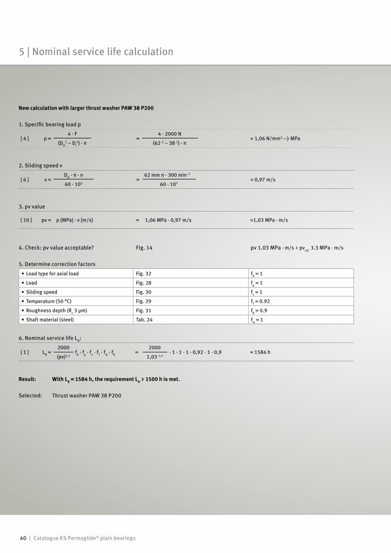
New calculation with larger thrust washer PAW 38 P200
1. Specific bearing load p
[ 4 ] p =4 · F
=4 · 2000 N
≈ 1,06 N/mm2 → MPa(DO
2 – DI2) · π (62 2 – 38 2) · π
2. Sliding speed v
[ 6 ] v =DO · π · n
=62 mm π · 300 min–1
≈ 0,97 m/s60 · 103 60 · 103
3. pv value
[ 10 ] pv = p [MPa] · v [m/s] = 1,06 MPa · 0,97 m/s ≈1,03 MPa · m/s
4. Check: pv value acceptable? Fig. 14 pv 1.03 MPa · m/s < pvzul. 3.3 MPa · m/s
5. Determine correction factors
• Load type for axial load Fig. 32 fA = 1
• Load Fig. 28 fp = 1
• Sliding speed Fig. 30 fv = 1
• Temperature (50 °C) Fig. 29 fT = 0.92
• Roughness depth (Rz 3 µm) Fig. 31 fR = 0.9
• Shaft material (steel) Tab. 24 fw = 1
6. Nominal service life LN:
[ 1 ] LN =2000
fA · fp · fv · fT · fw · fR =2000
· 1 · 1 · 1 · 0,92 · 1 · 0,9 = 1584 h(pv)1,5 1,03 1,5
Result: With LN = 1584 h, the requirement LN > 1500 h is met.
Selected: Thrust washer PAW 38 P200
5 | Nominal service life calculation
Catalogue KS Permaglide® plain bearings | 41
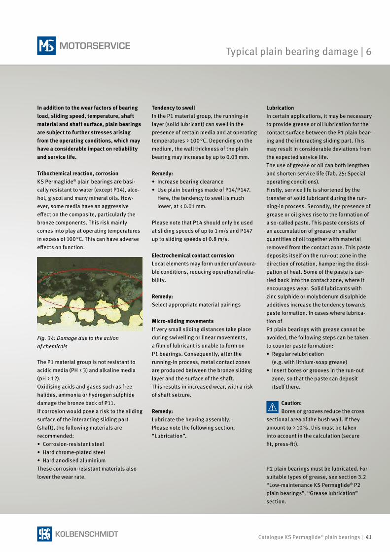
In addition to the wear factors of bearing load, sliding speed, temperature, shaft material and shaft surface, plain bearings are subject to further stresses arising from the operating conditions, which may have a considerable impact on reliability and service life.
Tribochemical reaction, corrosionKS Permaglide® plain bearings are basi-cally resistant to water (except P14), alco-hol, glycol and many mineral oils. How-ever, some media have an aggressive effect on the composite, particularly the bronze components. This risk mainly comes into play at operating temperatures in excess of 100 °C. This can have adverse effects on function.
Tendency to swellIn the P1 material group, the running-in layer (solid lubricant) can swell in the presence of certain media and at operating temperatures > 100 °C. Depending on the medium, the wall thickness of the plain bearing may increase by up to 0.03 mm.
Remedy: • Increase bearing clearance• Use plain bearings made of P14/P147.
Here, the tendency to swell is much lower, at < 0.01 mm.
Please note that P14 should only be used at sliding speeds of up to 1 m/s and P147 up to sliding speeds of 0.8 m/s.
Electrochemical contact corrosionLocal elements may form under unfavoura-ble conditions, reducing operational relia-bility.
Remedy: Select appropriate material pairings
Micro-sliding movementsIf very small sliding distances take place during swivelling or linear movements, a film of lubricant is unable to form on P1 bearings. Consequently, after the running-in process, metal contact zones are produced between the bronze sliding layer and the surface of the shaft.This results in increased wear, with a risk of shaft seizure.
Remedy: Lubricate the bearing assembly.Please note the following section, “Lubrication”.
LubricationIn certain applications, it may be necessary to provide grease or oil lubrication for the contact surface between the P1 plain bear-ing and the interacting sliding part. This may result in considerable deviations from the expected service life. The use of grease or oil can both lengthen and shorten service life (Tab. 25: Special operating conditions). Firstly, service life is shortened by the transfer of solid lubricant during the run-ning-in process. Secondly, the presence of grease or oil gives rise to the formation of a so-called paste. This paste consists of an accumulation of grease or smaller quantities of oil together with material removed from the contact zone. This paste deposits itself on the run-out zone in the direction of rotation, hampering the dissi-pation of heat. Some of the paste is car-ried back into the contact zone, where it encourages wear. Solid lubricants with zinc sulphide or molybdenum disulphide additives increase the tendency towards paste formation. In cases where lubrica-tion of P1 plain bearings with grease cannot be avoided, the following steps can be taken to counter paste formation:• Regular relubrication (e.g. with lithium-soap grease)• Insert bores or grooves in the run-out
zone, so that the paste can deposit itself there.
Caution:Bores or grooves reduce the cross
sectional area of the bush wall. If they amount to > 10 %, this must be taken into account in the calculation (secure fit, press-fit).
The P1 material group is not resistant to acidic media (PH < 3) and alkaline media (pH > 12).Oxidising acids and gases such as free halides, ammonia or hydrogen sulphide damage the bronze back of P11.If corrosion would pose a risk to the sliding surface of the interacting sliding part (shaft), the following materials are recommended:• Corrosion-resistant steel• Hard chrome-plated steel• Hard anodised aluminiumThese corrosion-resistant materials also lower the wear rate.
Fig. 34: Damage due to the action of chemicals
P2 plain bearings must be lubricated. For suitable types of grease, see section 3.2 “Low-maintenance KS Permaglide® P2 plain bearings”, “Grease lubrication” section.
Typical plain bearing damage | 6
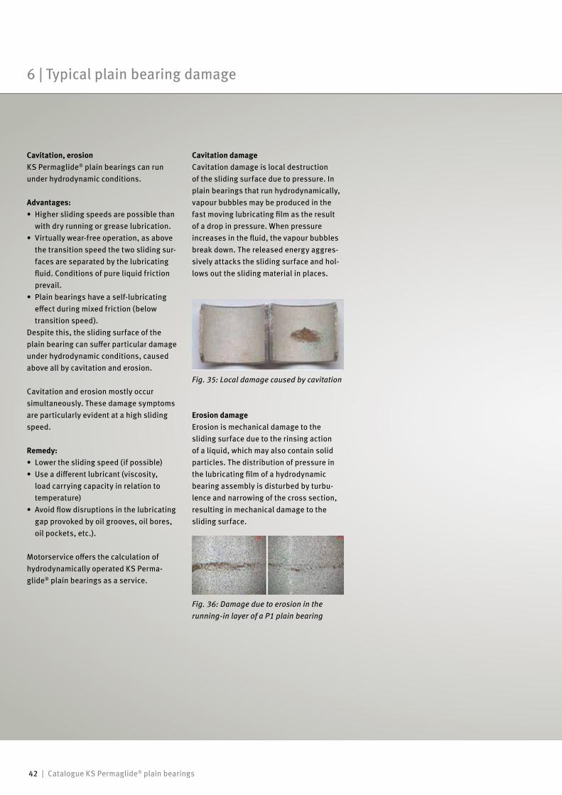
42 | Catalogue KS Permaglide® plain bearings
Cavitation, erosionKS Permaglide® plain bearings can run under hydrodynamic conditions.
Advantages:• Higher sliding speeds are possible than
with dry running or grease lubrication.• Virtually wear-free operation, as above
the transition speed the two sliding sur-faces are separated by the lubricating fluid. Conditions of pure liquid friction prevail.
• Plain bearings have a self-lubricating effect during mixed friction (below transition speed).
Despite this, the sliding surface of the plain bearing can suffer particular damage under hydrodynamic conditions, caused above all by cavitation and erosion.
Cavitation and erosion mostly occur simultaneously. These damage symptoms are particularly evident at a high sliding speed.
Remedy:• Lower the sliding speed (if possible)• Use a different lubricant (viscosity,
load carrying capacity in relation to temperature)
• Avoid flow disruptions in the lubricating gap provoked by oil grooves, oil bores, oil pockets, etc.).
Motorservice offers the calculation of hydrodynamically operated KS Perma-glide® plain bearings as a service.
Cavitation damageCavitation damage is local destruction of the sliding surface due to pressure. In plain bearings that run hydrodynamically, vapour bubbles may be produced in the fast moving lubricating film as the result of a drop in pressure. When pressure increases in the fluid, the vapour bubbles break down. The released energy aggres-sively attacks the sliding surface and hol-lows out the sliding material in places.
Fig. 36: Damage due to erosion in the running-in layer of a P1 plain bearing
Fig. 35: Local damage caused by cavitation
Erosion damageErosion is mechanical damage to the sliding surface due to the rinsing action of a liquid, which may also contain solid particles. The distribution of pressure in the lubricating film of a hydrodynamic bearing assembly is disturbed by turbu-lence and narrowing of the cross section, resulting in mechanical damage to the sliding surface.
6 | Typical plain bearing damage
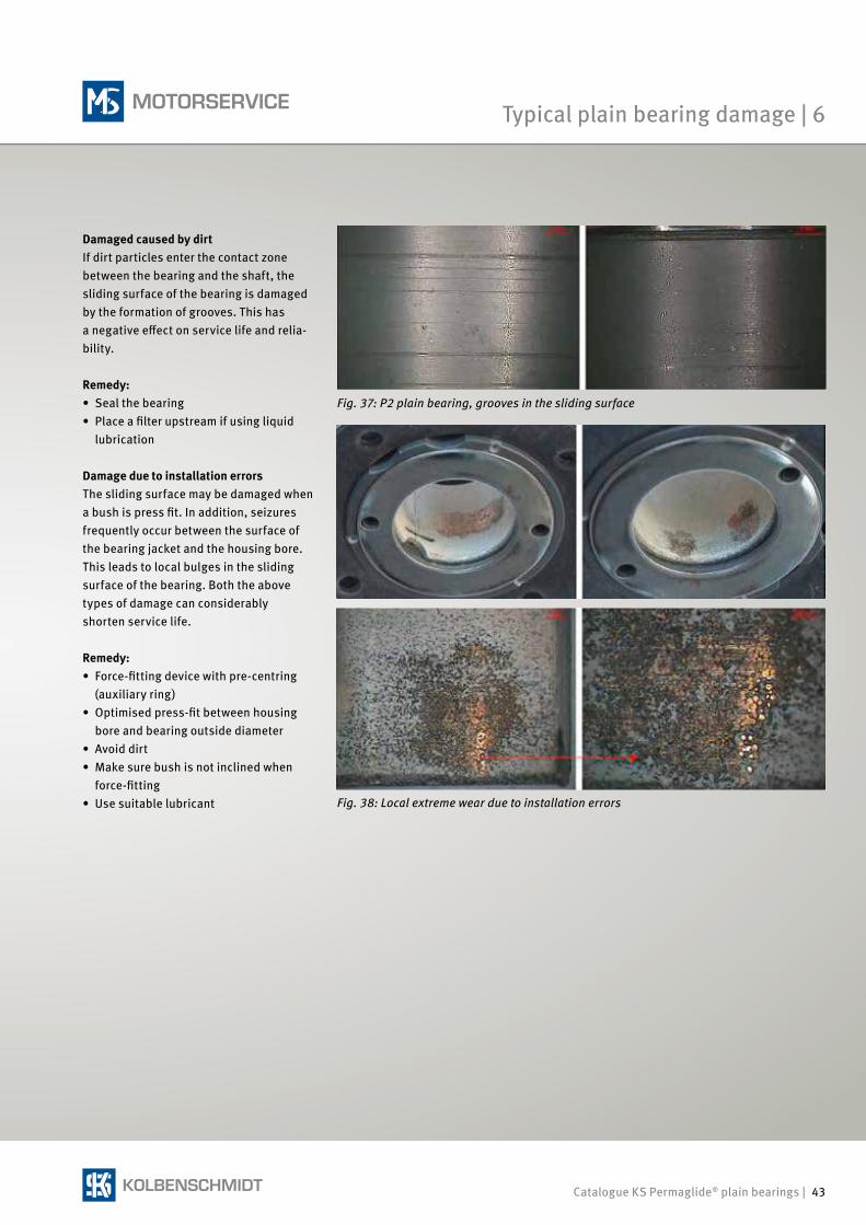
Catalogue KS Permaglide® plain bearings | 43
Damaged caused by dirtIf dirt particles enter the contact zonebetween the bearing and the shaft, thesliding surface of the bearing is damagedby the formation of grooves. This has a negative effect on service life and relia-bility.
Remedy:• Seal the bearing• Place a filter upstream if using liquid
lubrication
Damage due to installation errorsThe sliding surface may be damaged when a bush is press fit. In addition, seizures frequently occur between the surface of the bearing jacket and the housing bore. This leads to local bulges in the sliding surface of the bearing. Both the above types of damage can considerably shorten service life.
Remedy: • Force-fitting device with pre-centring
(auxiliary ring)• Optimised press-fit between housing
bore and bearing outside diameter• Avoid dirt• Make sure bush is not inclined when
force-fitting• Use suitable lubricant Fig. 38: Local extreme wear due to installation errors
Fig. 37: P2 plain bearing, grooves in the sliding surface
Typical plain bearing damage | 6
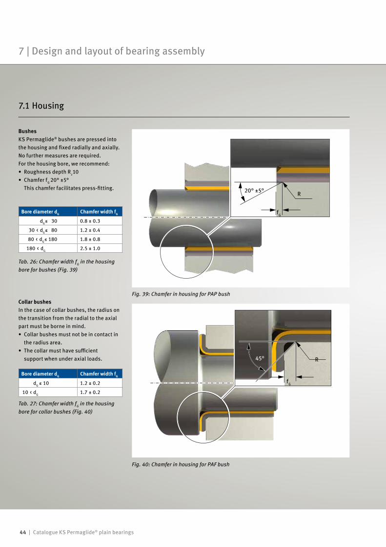
44 | Catalogue KS Permaglide® plain bearings
45°
fG
R
BushesKS Permaglide® bushes are pressed into the housing and fixed radially and axially. No further measures are required.For the housing bore, we recommend:• Roughness depth Rz10• Chamfer fG 20° ±5°
This chamfer facilitates press-fitting.
Tab. 27: Chamfer width fG in the housing bore for collar bushes (Fig. 40)
Bore diameter dG Chamfer width fG
dG ≤ 10 1.2 ± 0.2
10 < dG 1.7 ± 0.2
Collar bushesIn the case of collar bushes, the radius on the transition from the radial to the axial part must be borne in mind. • Collar bushes must not be in contact in
the radius area.• The collar must have sufficient
support when under axial loads.
Tab. 26: Chamfer width fG in the housing bore for bushes (Fig. 39)
Bore diameter dG Chamfer width fG
dG≤ 30 0.8 ± 0.3
30 < dG≤ 80 1.2 ± 0.4
80 < dG≤ 180 1.8 ± 0.8
180 < dG 2.5 ± 1.0
Fig. 40: Chamfer in housing for PAF bush
Fig. 39: Chamfer in housing for PAP bush
20° ±5°
fG
R
7 | Design and layout of bearing assembly
7.1 Housing
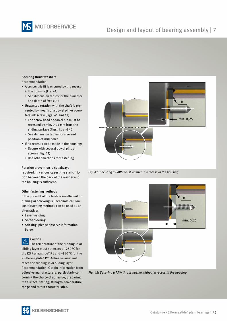
Catalogue KS Permaglide® plain bearings | 45
Securing thrust washersRecommendation:• A concentric fit is ensured by the recess
in the housing (Fig. 41) • See dimension tables for the diameter
and depth of free cuts• Unwanted rotation with the shaft is pre-
vented by means of a dowel pin or coun-tersunk screw (Figs. 41 and 42)• The screw head or dowel pin must be
recessed by min. 0.25 mm from the sliding surface (Figs. 41 and 42)
• See dimension tables for size and position of drill holes.
• If no recess can be made in the housing:• Secure with several dowel pins or screws (Fig. 42)• Use other methods for fastening
Rotation prevention is not always required. In various cases, the static fric-tion between the back of the washer and the housing is sufficient.
Other fastening methodsIf the press fit of the bush is insufficient or pinning or screwing is uneconomical, low-cost fastening methods can be used as an alternative:• Laser welding• Soft-soldering• Sticking, please observe information
below.
Caution:The temperature of the running-in or
sliding layer must not exceed +280 °C for the KS Permaglide® P1 and +140 °C for the KS Permaglide® P2. Adhesive must not reach the running-in or sliding layer. Recommendation: Obtain information from adhesive manufacturers, particularly con-cerning the choice of adhesive, preparing the surface, setting, strength, temperature range and strain characteristics.
Fig. 42: Securing a PAW thrust washer without a recess in the housing
Fig. 41: Securing a PAW thrust washer in a recess in the housing
R
min. 0,25
min. 0,25
R
Design and layout of bearing assembly | 7
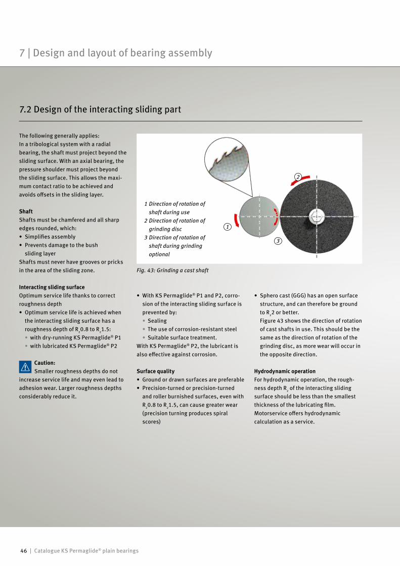
46 | Catalogue KS Permaglide® plain bearings
3
1
2
The following generally applies: In a tribological system with a radialbearing, the shaft must project beyond thesliding surface. With an axial bearing, thepressure shoulder must project beyond the sliding surface. This allows the maxi-mum contact ratio to be achieved and avoids offsets in the sliding layer.
ShaftShafts must be chamfered and all sharp edges rounded, which:• Simplifies assembly• Prevents damage to the bush
sliding layerShafts must never have grooves or pricks in the area of the sliding zone.
Interacting sliding surfaceOptimum service life thanks to correct roughness depth• Optimum service life is achieved when
the interacting sliding surface has a roughness depth of Rz0.8 to Rz1.5: • with dry-running KS Permaglide® P1
• with lubricated KS Permaglide® P2
Caution:Smaller roughness depths do not
increase service life and may even lead to adhesion wear. Larger roughness depths considerably reduce it.
• Sphero cast (GGG) has an open surface structure, and can therefore be ground to Rz2 or better. Figure 43 shows the direction of rotation of cast shafts in use. This should be the same as the direction of rotation of the grinding disc, as more wear will occur in the opposite direction.
Hydrodynamic operationFor hydrodynamic operation, the rough-ness depth Rz of the interacting sliding surface should be less than the smallest thickness of the lubricating film.Motorservice offers hydrodynamic calculation as a service.
Fig. 43: Grinding a cast shaft
• With KS Permaglide® P1 and P2, corro-sion of the interacting sliding surface is prevented by: • Sealing
• The use of corrosion-resistant steel• Suitable surface treatment.
With KS Permaglide® P2, the lubricant is also effective against corrosion.
Surface quality• Ground or drawn surfaces are preferable• Precision-turned or precision-turned
and roller burnished surfaces, even with Rz0.8 to Rz1.5, can cause greater wear (precision turning produces spiral scores)
1 Direction of rotation of shaft during use
2 Direction of rotation of grinding disc
3 Direction of rotation of shaft during grinding optional
7.2 Design of the interacting sliding part
7 | Design and layout of bearing assembly
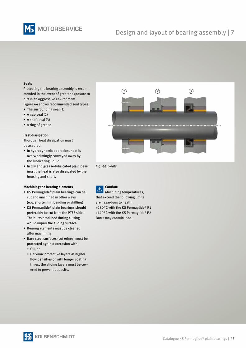
Catalogue KS Permaglide® plain bearings | 47
31 2
SealsProtecting the bearing assembly is recom-mended in the event of greater exposure to dirt in an aggressive environment. Figure 44 shows recommended seal types:• The surrounding seal (1)• A gap seal (2)• A shaft seal (3)• A ring of grease
Heat dissipationThorough heat dissipation must be assured.• In hydrodynamic operation, heat is
overwhelmingly conveyed away by the lubricating liquid.
• In dry and grease-lubricated plain bear-ings, the heat is also dissipated by the housing and shaft.
Machining the bearing elements• KS Permaglide® plain bearings can be
cut and machined in other ways (e.g. shortening, bending or drilling)
• KS Permaglide® plain bearings should preferably be cut from the PTFE side. The burrs produced during cutting would impair the sliding surface
• Bearing elements must be cleaned after machining
• Bare steel surfaces (cut edges) must be protected against corrosion with: • Oil, or
• Galvanic protective layers At higher flow densities or with longer coating times, the sliding layers must be cov-ered to prevent deposits.
Caution:Machining temperatures,
that exceed the following limits are hazardous to health: +280 °C with the KS Permaglide® P1 +140 °C with the KS Permaglide® P2 Burrs may contain lead.
Fig. 44: Seals
Design and layout of bearing assembly | 7
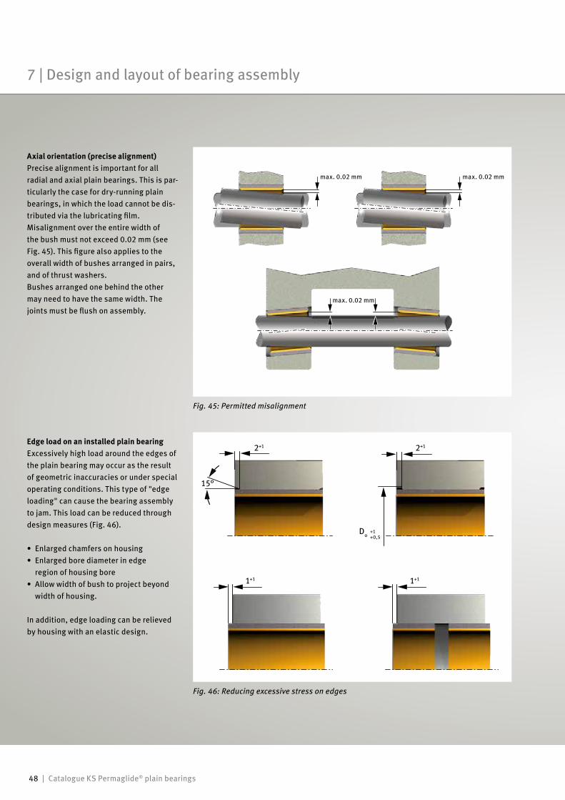
48 | Catalogue KS Permaglide® plain bearings
Axial orientation (precise alignment)Precise alignment is important for all radial and axial plain bearings. This is par-ticularly the case for dry-running plain bearings, in which the load cannot be dis-tributed via the lubricating film.Misalignment over the entire width of the bush must not exceed 0.02 mm (see Fig. 45). This figure also applies to the overall width of bushes arranged in pairs, and of thrust washers.Bushes arranged one behind the other may need to have the same width. The joints must be flush on assembly.
Edge load on an installed plain bearingExcessively high load around the edges of the plain bearing may occur as the result of geometric inaccuracies or under special operating conditions. This type of "edge loading" can cause the bearing assembly to jam. This load can be reduced through design measures (Fig. 46).
• Enlarged chamfers on housing• Enlarged bore diameter in edge region of housing bore• Allow width of bush to project beyond width of housing.
In addition, edge loading can be relieved by housing with an elastic design.
Fig. 45: Permitted misalignment
Fig. 46: Reducing excessive stress on edges
max. 0.02 mm
max. 0.02 mm
2+1
1+1 1+1
15°
2+1
max. 0.02 mm
+1 +0,5
Do
7 | Design and layout of bearing assembly
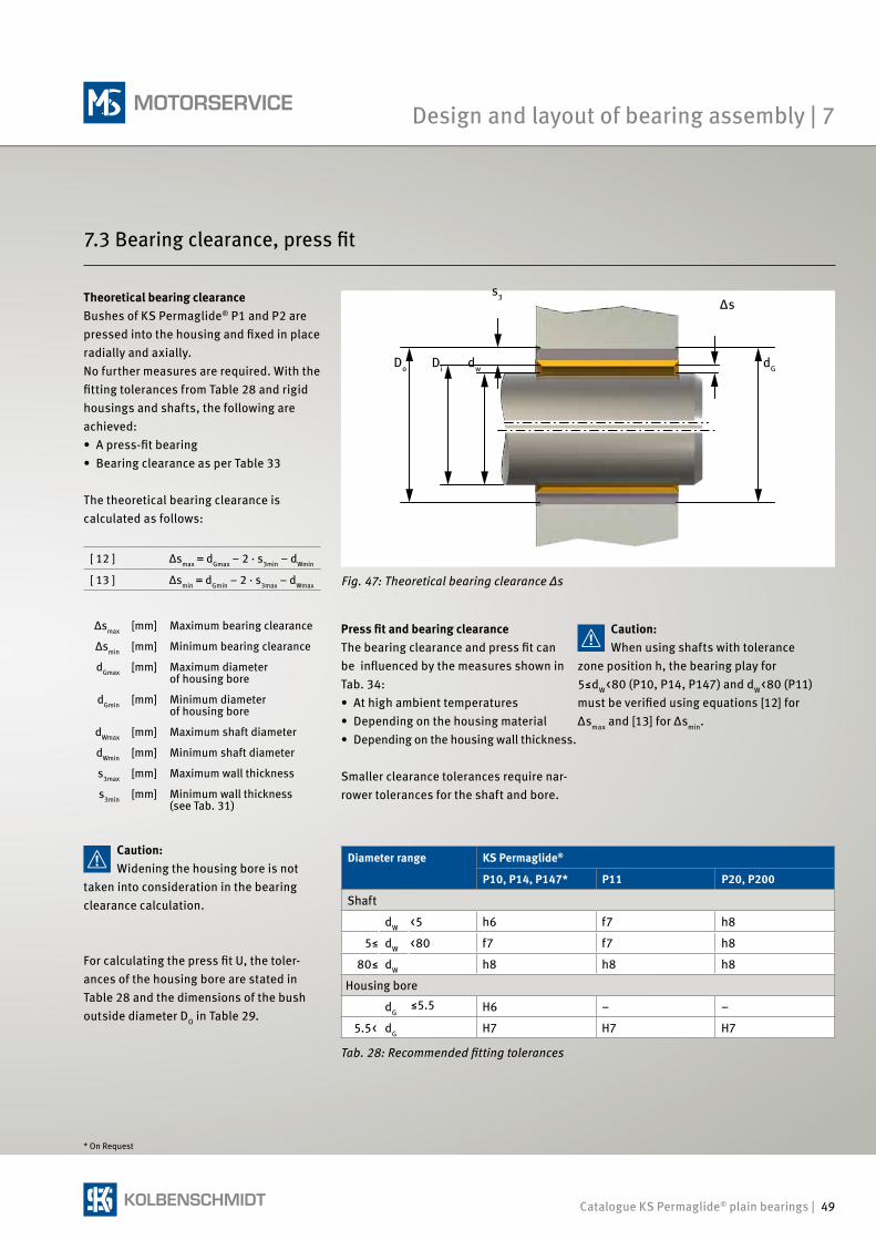
Catalogue KS Permaglide® plain bearings | 49
Theoretical bearing clearanceBushes of KS Permaglide® P1 and P2 are pressed into the housing and fixed in place radially and axially.No further measures are required. With the fitting tolerances from Table 28 and rigid housings and shafts, the following are achieved:• A press-fit bearing• Bearing clearance as per Table 33
The theoretical bearing clearance is calculated as follows:
[ 12 ] Δsmax = dGmax – 2 · s3min – dWmin
[ 13 ] Δsmin = dGmin – 2 · s3max – dWmax
Press fit and bearing clearanceThe bearing clearance and press fit can be influenced by the measures shown in Tab. 34:• At high ambient temperatures• Depending on the housing material• Depending on the housing wall thickness.
Smaller clearance tolerances require nar-rower tolerances for the shaft and bore.
For calculating the press fit U, the toler-ances of the housing bore are stated in Table 28 and the dimensions of the bush outside diameter DO in Table 29.
Δsmax [mm] Maximum bearing clearance
Δsmin [mm] Minimum bearing clearance
dGmax [mm] Maximum diameter of housing bore
dGmin [mm] Minimum diameter of housing bore
dWmax [mm] Maximum shaft diameter
dWmin [mm] Minimum shaft diameter
s3max [mm] Maximum wall thickness
s3min [mm] Minimum wall thickness (see Tab. 31)
Tab. 28: Recommended fitting tolerances
* On Request
Fig. 47: Theoretical bearing clearance Δs
s3
Di dw dG
Δs
Do
Caution:Widening the housing bore is not
taken into consideration in the bearing clearance calculation.
Caution:When using shafts with tolerance
zone position h, the bearing play for 5≤dW<80 (P10, P14, P147) and dW<80 (P11) must be verified using equations [12] for Δsmax and [13] for Δsmin.
Diameter range KS Permaglide®
P10, P14, P147* P11 P20, P200
Shaft
dW <5 h6 f7 h8
5≤ dW <80 f7 f7 h8
80≤ dW h8 h8 h8
Housing bore
dG≤5.5 H6 – –
5.5< dG H7 H7 H7
7.3 Bearing clearance, press fit
Design and layout of bearing assembly | 7
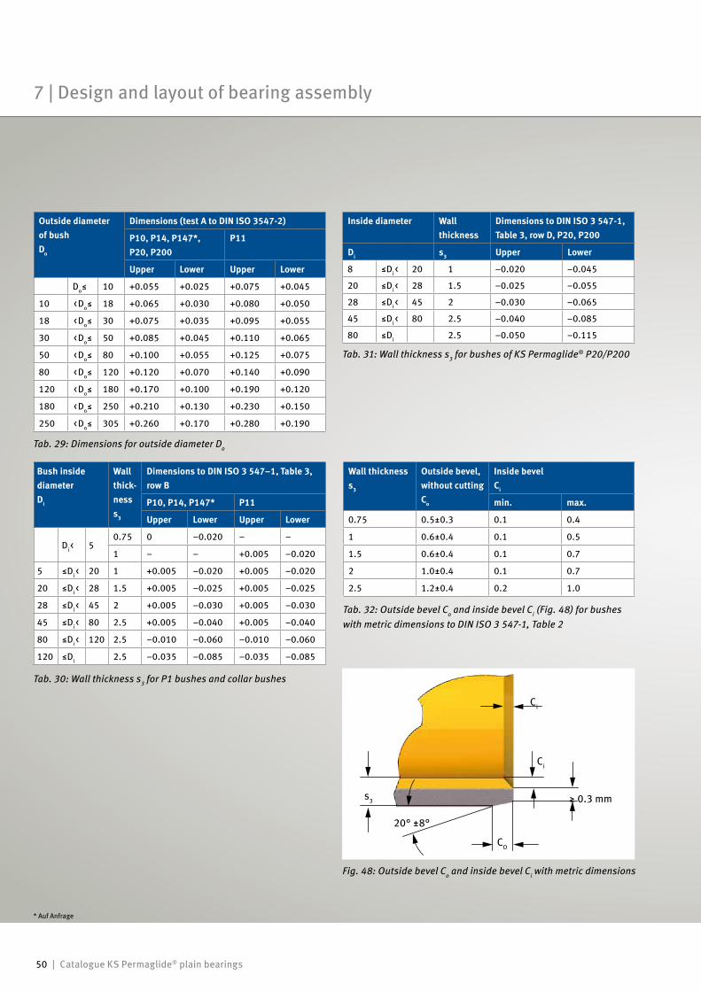
50 | Catalogue KS Permaglide® plain bearings
* Auf Anfrage
Fig. 48: Outside bevel Co and inside bevel Ci with metric dimensions
Tab. 32: Outside bevel Co and inside bevel Ci (Fig. 48) for bushes with metric dimensions to DIN ISO 3 547-1, Table 2
Wall thicknesss3
Outside bevel, without cuttingCo
Inside bevelCi
min. max.
0.75 0.5±0.3 0.1 0.4
1 0.6±0.4 0.1 0.5
1.5 0.6±0.4 0.1 0.7
2 1.0±0.4 0.1 0.7
2.5 1.2±0.4 0.2 1.0
Tab. 31: Wall thickness s3 for bushes of KS Permaglide® P20/P200
Inside diameter Wall thickness
Dimensions to DIN ISO 3 547-1,Table 3, row D, P20, P200
Di s3 Upper Lower
8 ≤Di< 20 1 –0.020 –0.045
20 ≤Di< 28 1.5 –0.025 –0.055
28 ≤Di< 45 2 –0.030 –0.065
45 ≤Di< 80 2.5 –0.040 –0.085
80 ≤Di 2.5 –0.050 –0.115
Tab. 30: Wall thickness s3 for P1 bushes and collar bushes
Bush inside diameter Di
Wall thick-ness s3
Dimensions to DIN ISO 3 547–1, Table 3,row B
P10, P14, P147* P11
Upper Lower Upper Lower
Di< 50.75 0 –0.020 – –
1 – – +0.005 –0.020
5 ≤Di< 20 1 +0.005 –0.020 +0.005 –0.020
20 ≤Di< 28 1.5 +0.005 –0.025 +0.005 –0.025
28 ≤Di< 45 2 +0.005 –0.030 +0.005 –0.030
45 ≤Di< 80 2.5 +0.005 –0.040 +0.005 –0.040
80 ≤Di< 120 2.5 –0.010 –0.060 –0.010 –0.060
120 ≤Di 2.5 –0.035 –0.085 –0.035 –0.085
Tab. 29: Dimensions for outside diameter Do
Outside diameter of bush Do
Dimensions (test A to DIN ISO 3547-2)
P10, P14, P147*, P20, P200
P11
Upper Lower Upper Lower
Do≤ 10 +0.055 +0.025 +0.075 +0.045
10 <Do≤ 18 +0.065 +0.030 +0.080 +0.050
18 <Do≤ 30 +0.075 +0.035 +0.095 +0.055
30 <Do≤ 50 +0.085 +0.045 +0.110 +0.065
50 <Do≤ 80 +0.100 +0.055 +0.125 +0.075
80 <Do≤ 120 +0.120 +0.070 +0.140 +0.090
120 <Do≤ 180 +0.170 +0.100 +0.190 +0.120
180 <Do≤ 250 +0.210 +0.130 +0.230 +0.150
250 <Do≤ 305 +0.260 +0.170 +0.280 +0.190
Ci
CO
s3
20° ±8°
Ci
≥ 0.3 mm
7 | Design and layout of bearing assembly
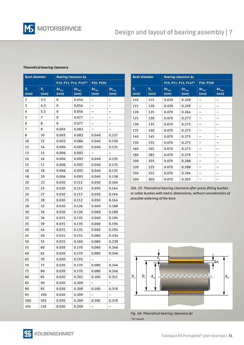
Catalogue KS Permaglide® plain bearings | 51
Theoretical bearing clearance
Bush diameter Bearing clearance Δs
P10. P11. P14. P147* P20. P200
Di (mm)
Do (mm)
Δsmin (mm)
Δsmax (mm)
Δsmin (mm)
Δsmax (mm)
2 3.5 0 0.054 – –
3 4.5 0 0.054 – –
4 5.5 0 0.056 – –
5 7 0 0.077 – –
6 8 0 0.077 – –
7 9 0.003 0.083 – –
8 10 0.003 0.083 0.040 0.127
10 12 0.003 0.086 0.040 0.130
12 14 0.006 0.092 0.040 0.135
13 15 0.006 0.092 – –
14 16 0.006 0.092 0.040 0.135
15 17 0.006 0.092 0.040 0.135
16 18 0.006 0.092 0.040 0.135
18 20 0.006 0.095 0.040 0.138
20 23 0.010 0.112 0.050 0.164
22 25 0.010 0.112 0.050 0.164
24 27 0.010 0.112 0.050 0.164
25 28 0.010 0.112 0.050 0.164
28 32 0.010 0.126 0.060 0.188
30 34 0.010 0.126 0.060 0.188
32 36 0.015 0.135 0.060 0.194
35 39 0.015 0.135 0.060 0.194
40 44 0.015 0.135 0.060 0.194
45 50 0.015 0.155 0.080 0.234
50 55 0.015 0.160 0.080 0.239
55 60 0.020 0.170 0.080 0.246
60 65 0.020 0.170 0.080 0.246
65 70 0.020 0.170 – –
70 75 0.020 0.170 0.080 0.246
75 80 0.020 0.170 0.080 0.246
80 85 0.020 0.201 0.100 0.311
85 90 0.020 0.209 – –
90 95 0.020 0.209 0.100 0.319
95 100 0.020 0.209 – –
100 105 0.020 0.209 0.100 0.319
105 110 0.020 0.209 – –
Fig. 49: Theoretical bearing clearance Δs
Tab. 33: Theoretical bearing clearance after press-fitting bushes or collar bushes with metric dimensions, without consideration of possible widening of the bore
Bush diameter Bearing clearance Δs
P10. P11. P14. P147* P20. P200
Di (mm)
Do (mm)
Δsmin (mm)
Δsmax (mm)
Δsmin (mm)
Δsmax (mm)
110 115 0.020 0.209 – –
115 120 0.020 0.209 – –
120 125 0.070 0.264 – –
125 130 0.070 0.273 – –
130 135 0.070 0.273 – –
135 140 0.070 0.273 – –
140 145 0.070 0.273 – –
150 155 0.070 0.273 – –
160 165 0.070 0.273 – –
180 185 0.070 0.279 – –
200 205 0.070 0.288 – –
220 225 0.070 0.288 – –
250 255 0.070 0.294 – –
300 305 0.070 0.303 – –
* On request
Do Di dw
s3
dG
Δs
Design and layout of bearing assembly | 7
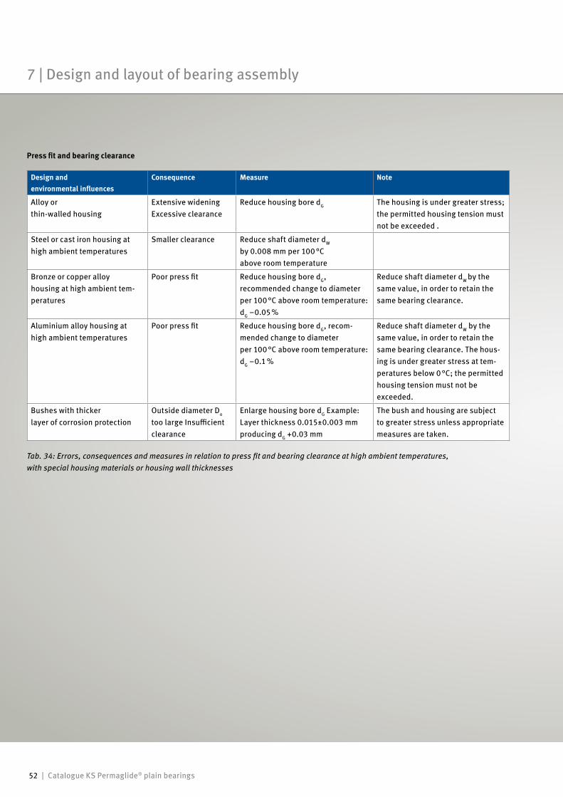
52 | Catalogue KS Permaglide® plain bearings
Press fit and bearing clearance
Tab. 34: Errors, consequences and measures in relation to press fit and bearing clearance at high ambient temperatures, with special housing materials or housing wall thicknesses
Design andenvironmental influences
Consequence Measure Note
Alloy orthin-walled housing
Extensive wideningExcessive clearance
Reduce housing bore dG The housing is under greater stress; the permitted housing tension must not be exceeded .
Steel or cast iron housing at high ambient temperatures
Smaller clearance Reduce shaft diameter dW by 0.008 mm per 100 °C above room temperature
Bronze or copper alloy housing at high ambient tem-peratures
Poor press fit Reduce housing bore dG, recommended change to diameter per 100 °C above room temperature: dG –0.05 %
Reduce shaft diameter dW by the same value, in order to retain the same bearing clearance.
Aluminium alloy housing at high ambient temperatures
Poor press fit Reduce housing bore dG, recom-mended change to diameter per 100 °C above room temperature:dG –0.1 %
Reduce shaft diameter dW by the same value, in order to retain the same bearing clearance. The hous-ing is under greater stress at tem-peratures below 0 °C; the permitted housing tension must not be exceeded.
Bushes with thicker layer of corrosion protection
Outside diameter Do too large Insufficient clearance
Enlarge housing bore dG Example:Layer thickness 0.015±0.003 mmproducing dG +0.03 mm
The bush and housing are subject to greater stress unless appropriate measures are taken.
7 | Design and layout of bearing assembly
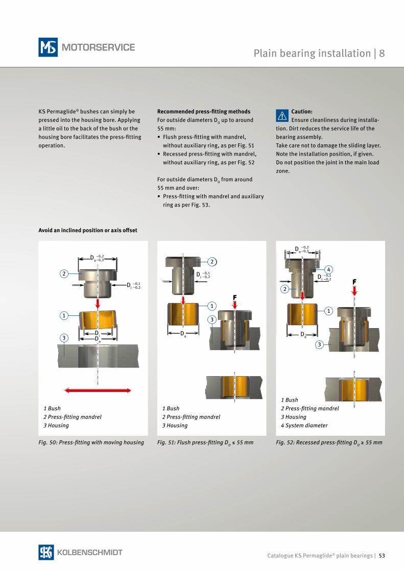
Catalogue KS Permaglide® plain bearings | 53
332
1
3
32
1
3
2
1
4
F
FDi
–0,1–0,2 Di
–0,1–0,2
Do–0,2–0,3
Di–0,1–0,2
Do–0,2–0,3
Do
Di Do Do
3
Recommended press-fitting methodsFor outside diameters DO up to around 55 mm:• Flush press-fitting with mandrel,
without auxiliary ring, as per Fig. 51• Recessed press-fitting with mandrel,
without auxiliary ring, as per Fig. 52
For outside diameters DO from around 55 mm and over:• Press-fitting with mandrel and auxiliary
ring as per Fig. 53.
KS Permaglide® bushes can simply be pressed into the housing bore. Applying a little oil to the back of the bush or the housing bore facilitates the press-fitting operation.
1 Bush 2 Press-fitting mandrel 3 Housing
Fig. 50: Press-fitting with moving housing
Avoid an inclined position or axis offset
1 Bush 2 Press-fitting mandrel 3 Housing
Fig. 51: Flush press-fitting DO ≤ 55 mm
1 Bush 2 Press-fitting mandrel 3 Housing 4 System diameter
Fig. 52: Recessed press-fitting DO ≥ 55 mm
Caution:Ensure cleanliness during installa-
tion. Dirt reduces the service life of the bearing assembly.Take care not to damage the sliding layer. Note the installation position, if given.Do not position the joint in the main load zone.
Plain bearing installation | 8
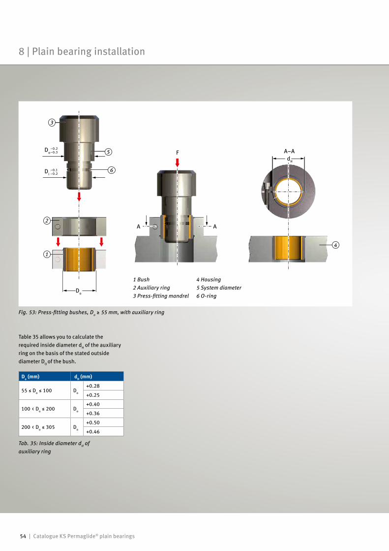
54 | Catalogue KS Permaglide® plain bearings
3
1
2
4
5
6
8 | Plain bearing installation
Table 35 allows you to calculate the required inside diameter dH of the auxiliary ring on the basis of the stated outside diameter DO of the bush.
Tab. 35: Inside diameter dH of auxiliary ring
Do (mm) dH (mm)
55 ≤ Do ≤ 100 Do
+0.28
+0.25
100 < Do ≤ 200 Do
+0.40
+0.36
200 < Do ≤ 305 Do
+0.50
+0.46
1 Bush 4 Housing 2 Auxiliary ring 5 System diameter 3 Press-fitting mandrel 6 O-ring
Fig. 53: Press-fitting bushes, Do ≥ 55 mm, with auxiliary ring
F
AA
A–A
Di–0.1–0.2
Do–0.2–0.3
Do
dH
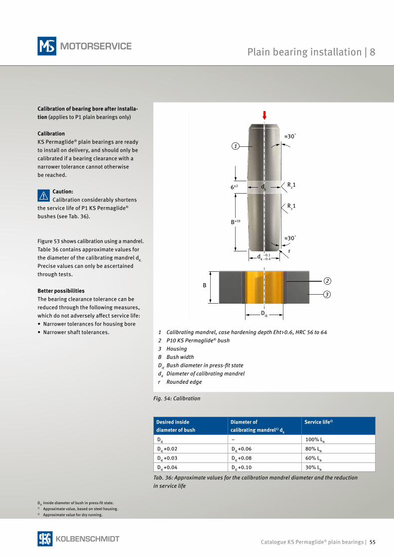
Catalogue KS Permaglide® plain bearings | 55
3
1
2
Plain bearing installation | 8
Calibration of bearing bore after installa-tion (applies to P1 plain bearings only)
CalibrationKS Permaglide® plain bearings are ready to install on delivery, and should only be calibrated if a bearing clearance with a narrower tolerance cannot otherwise be reached.
Figure 53 shows calibration using a mandrel.Table 36 contains approximate values for the diameter of the calibrating mandrel dK.
Precise values can only be ascertained through tests.
Better possibilitiesThe bearing clearance tolerance can be reduced through the following measures, which do not adversely affect service life:• Narrower tolerances for housing bore• Narrower shaft tolerances.
Caution:Calibration considerably shortens
the service life of P1 KS Permaglide® bushes (see Tab. 36).
Tab. 36: Approximate values for the calibration mandrel diameter and the reduction in service life
DiE Inside diameter of bush in press-fit state.1) Approximate value, based on steel housing.2) Approximate value for dry running.
Desired inside diameter of bush
Diameter of calibrating mandrel1) dK
Service life2)
DiE – 100% LN
DiE +0.02 DiE +0.06 80% LN
DiE +0.03 DiE +0.08 60% LN
DiE +0.04 DiE +0.10 30% LN
Fig. 54: Calibration
1 Calibrating mandrel, case hardening depth Eht>0.6, HRC 56 to 642 P10 KS Permaglide® bush3 HousingB Bush widthDiE Bush diameter in press-fit statedK Diameter of calibrating mandrelr Rounded edge
Rz1
Rz1
r
≈30΄
≈30΄
DiE
B
B+10
dk6±2
dk–0.1–0.4
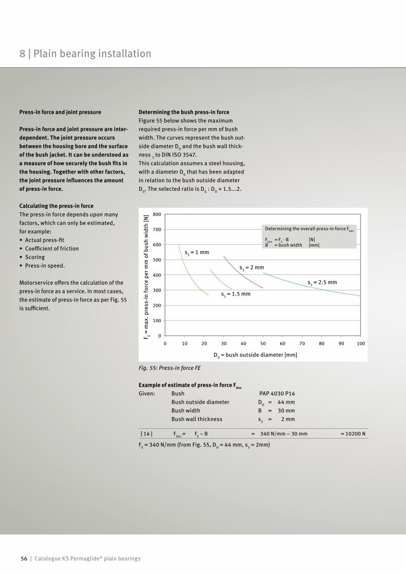
56 | Catalogue KS Permaglide® plain bearings
Determining the bush press-in forceFigure 55 below shows the maximum required press-in force per mm of bush width. The curves represent the bush out-side diameter DO and the bush wall thick-ness 3 to DIN ISO 3547.This calculation assumes a steel housing, with a diameter DG that has been adapted in relation to the bush outside diameter DO. The selected ratio is DG : DO ≈ 1.5...2.
Press-in force and joint pressure
Press-in force and joint pressure are inter-dependent. The joint pressure occurs between the housing bore and the surface of the bush jacket. It can be understood as a measure of how securely the bush fits in the housing. Together with other factors, the joint pressure influences the amount of press-in force.
Calculating the press-in forceThe press-in force depends upon many factors, which can only be estimated, for example:• Actual press-fit• Coefficient of friction• Scoring• Press-in speed.
Motorservice offers the calculation of the press-in force as a service. In most cases, the estimate of press-in force as per Fig. 55 is sufficient.
Example of estimate of press-in force FGes
Given: Bush PAP 4030 P14 Bush outside diameter DO = 44 mm Bush width B = 30 mm Bush wall thickness s3 = 2 mm
F E = m
ax. p
ress
-in fo
rce
per m
m o
f bus
h w
idth
[N]
DO = bush outside diameter [mm]
s3 = 1 mm
s3 = 1.5 mm
s3 = 2 mm
s3 = 2.5 mm
Determining the overall press-in force FGes
FGes = FE · B [N]B = bush width [mm]
FE = 340 N/mm (from Fig. 55, DO = 44 mm, s3 = 2mm)
[ 14 ] FGes = FE – B = 340 N/mm – 30 mm = 10200 N
Fig. 55: Press-in force FE
8 | Plain bearing installation
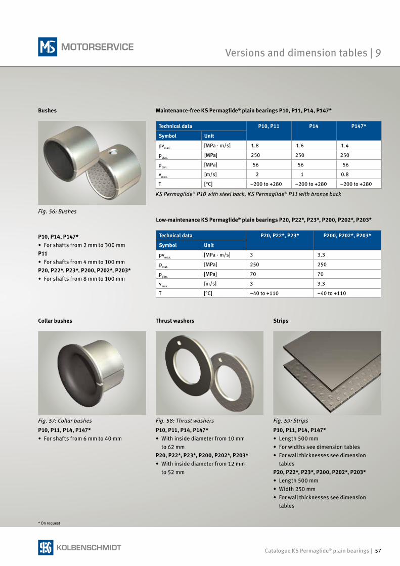
Catalogue KS Permaglide® plain bearings | 57
Thrust washers Strips
Maintenance-free KS Permaglide® plain bearings P10, P11, P14, P147*Bushes
Technical data P20, P22*, P23* P200, P202*, P203*
Symbol Unit
pvmax. [MPa · m/s] 3 3.3
pstat. [MPa] 250 250
pdyn. [MPa] 70 70
vmax. [m/s] 3 3.3
T [°C] –40 to +110 –40 to +110
Low-maintenance KS Permaglide® plain bearings P20, P22*, P23*, P200, P202*, P203*
KS Permaglide® P10 with steel back, KS Permaglide® P11 with bronze back
Technical data P10, P11 P14 P147*
Symbol Unit
pvmax. [MPa · m/s] 1.8 1.6 1.4
pstat. [MPa] 250 250 250
pdyn. [MPa] 56 56 56
vmax. [m/s] 2 1 0.8
T [°C] –200 to +280 –200 to +280 –200 to +280
Fig. 59: Strips
P10, P11, P14, P147*• Length 500 mm• For widths see dimension tables• For wall thicknesses see dimension
tablesP20, P22*, P23*, P200, P202*, P203*• Length 500 mm• Width 250 mm• For wall thicknesses see dimension
tables
Fig. 58: Thrust washers
P10, P11, P14, P147*• With inside diameter from 10 mm to 62 mmP20, P22*, P23*, P200, P202*, P203*• With inside diameter from 12 mm to 52 mm
Fig. 57: Collar bushes
P10, P11, P14, P147*• For shafts from 6 mm to 40 mm
Collar bushes
P10, P14, P147*• For shafts from 2 mm to 300 mmP11• For shafts from 4 mm to 100 mmP20, P22*, P23*, P200, P202*, P203*• For shafts from 8 mm to 100 mm
* On request
Fig. 56: Bushes
Versions and dimension tables | 9
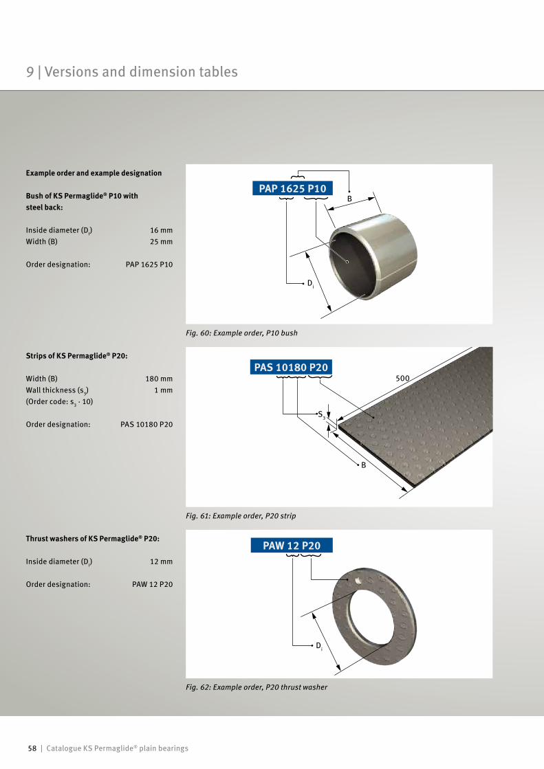
58 | Catalogue KS Permaglide® plain bearings
Example order and example designation
Bush of KS Permaglide® P10 with steel back:
Inside diameter (DI) 16 mmWidth (B) 25 mm
Order designation: PAP 1625 P10
Thrust washers of KS Permaglide® P20:
Inside diameter (Di) 12 mm
Order designation: PAW 12 P20
Strips of KS Permaglide® P20:
Width (B) 180 mmWall thickness (s3) 1 mm (Order code: s3 · 10)
Order designation: PAS 10180 P20
Fig. 60: Example order, P10 bush
PAP 1625 P10
PAS 10180 P20
PAW 12 P20
Fig. 62: Example order, P20 thrust washer
Fig. 61: Example order, P20 strip
B
Di
500
B
S3
Di
9 | Versions and dimension tables
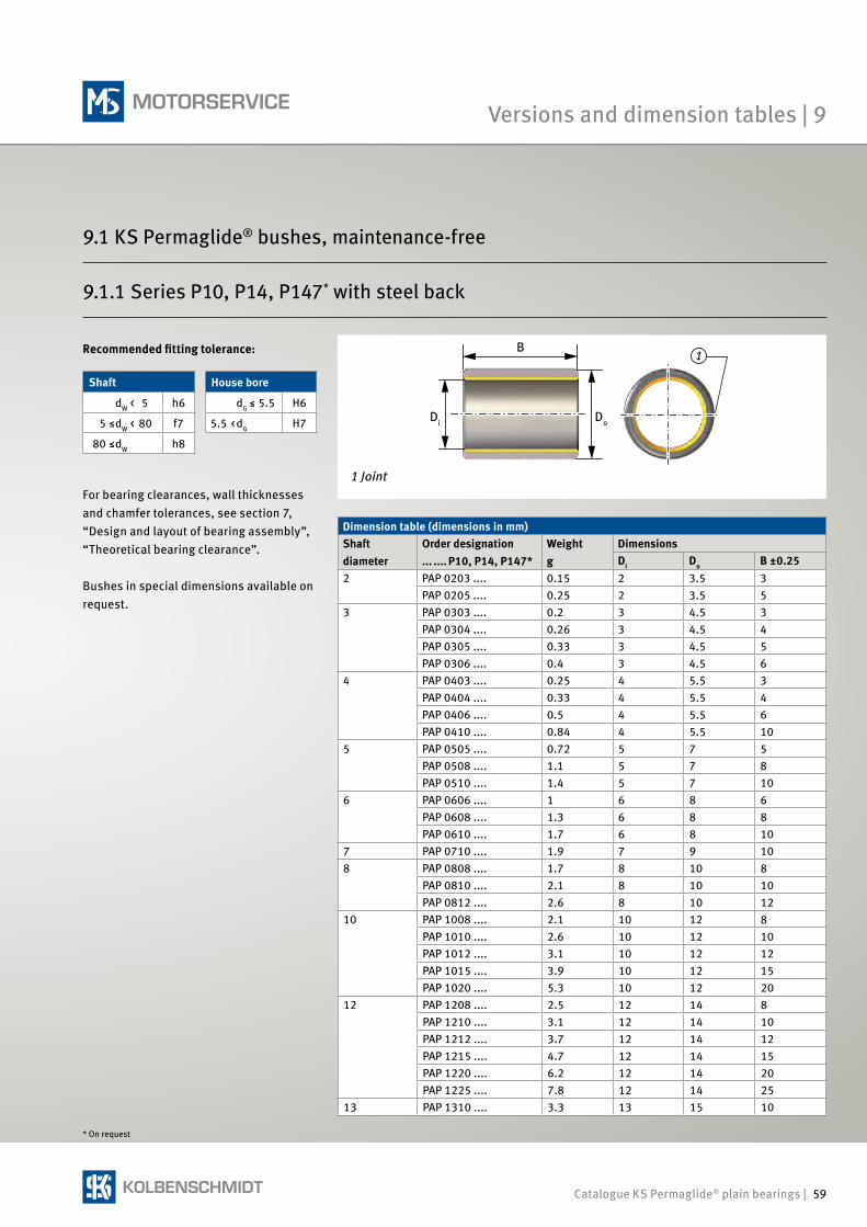
Catalogue KS Permaglide® plain bearings | 59
1Recommended fitting tolerance:
Dimension table (dimensions in mm)Shaft diameter
Order designation... .... P10, P14, P147*
Weightg
DimensionsDi Do B ±0.25
2 PAP 0203 .... 0.15 2 3.5 3PAP 0205 .... 0.25 2 3.5 5
3 PAP 0303 .... 0.2 3 4.5 3PAP 0304 .... 0.26 3 4.5 4PAP 0305 .... 0.33 3 4.5 5PAP 0306 .... 0.4 3 4.5 6
4 PAP 0403 .... 0.25 4 5.5 3PAP 0404 .... 0.33 4 5.5 4PAP 0406 .... 0.5 4 5.5 6PAP 0410 .... 0.84 4 5.5 10
5 PAP 0505 .... 0.72 5 7 5PAP 0508 .... 1.1 5 7 8PAP 0510 .... 1.4 5 7 10
6 PAP 0606 .... 1 6 8 6PAP 0608 .... 1.3 6 8 8PAP 0610 .... 1.7 6 8 10
7 PAP 0710 .... 1.9 7 9 108 PAP 0808 .... 1.7 8 10 8
PAP 0810 .... 2.1 8 10 10PAP 0812 .... 2.6 8 10 12
10 PAP 1008 .... 2.1 10 12 8PAP 1010 .... 2.6 10 12 10PAP 1012 .... 3.1 10 12 12PAP 1015 .... 3.9 10 12 15PAP 1020 .... 5.3 10 12 20
12 PAP 1208 .... 2.5 12 14 8PAP 1210 .... 3.1 12 14 10PAP 1212 .... 3.7 12 14 12PAP 1215 .... 4.7 12 14 15PAP 1220 .... 6.2 12 14 20PAP 1225 .... 7.8 12 14 25
13 PAP 1310 .... 3.3 13 15 10
For bearing clearances, wall thicknesses and chamfer tolerances, see section 7, “Design and layout of bearing assembly”, “Theoretical bearing clearance”.
Bushes in special dimensions available on request.
Shaft House bore
dW < 5 h6 dG ≤ 5.5 H6
5 ≤dW < 80 f7 5.5 <dG H7
80 ≤dW h8
* On request
B
Di Do
1 Joint
9.1.1 Series P10, P14, P147* with steel back
Versions and dimension tables | 9
9.1 KS Permaglide® bushes, maintenance-free
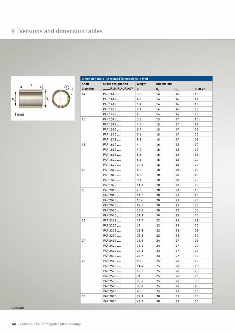
60 | Catalogue KS Permaglide® plain bearings
1
Dimension table · continued (dimensions in mm)Shaft diameter
Order designation ... .... P10, P14, P147*
Weight g
DimensionsDi Do B ±0.25
14 PAP 1410 .... 3.6 14 16 10
PAP 1412 .... 4.3 14 16 12
PAP 1415 .... 5.4 14 16 15
PAP 1420 .... 7.1 14 16 20
PAP 1425 .... 9 14 16 25
15 PAP 1510 .... 3.8 15 17 10
PAP 1512 .... 4.6 15 17 12
PAP 1515 .... 5.7 15 17 15
PAP 1520 .... 7.6 15 17 20
PAP 1525 .... 9.5 15 17 25
16 PAP 1610 .... 4 16 18 10
PAP 1612 .... 4.9 16 18 12
PAP 1615 .... 6.1 16 18 15
PAP 1620 .... 8.1 16 18 20
PAP 1625 .... 10.1 16 18 25
18 PAP 1810 .... 4.5 18 20 10
PAP 1815 .... 6.8 18 20 15
PAP 1820 .... 9.1 18 20 20
PAP 1825 .... 11.3 18 20 25
20 PAP 2010 .... 7.8 20 23 10
PAP 2015 .... 11.7 20 23 15
PAP 2020 .... 15.6 20 23 20
PAP 2025 .... 19.5 20 23 25
PAP 2030 .... 23.4 20 23 30
PAP 2040 .... 31.2 20 23 40
22 PAP 2215 .... 12.7 22 25 15
PAP 2220 .... 17 22 25 20
PAP 2225 .... 21.3 22 25 25
PAP 2230 .... 25.5 22 25 30
24 PAP 2415 .... 13.8 24 27 15
PAP 2420 .... 18.5 24 27 20
PAP 2425 .... 23.1 24 27 25
PAP 2430 .... 27.7 24 27 30
25 PAP 2510 .... 9.6 25 28 10
PAP 2515 .... 14.4 25 28 15
PAP 2520 .... 19.2 25 28 20
PAP 2525 .... 24 25 28 25
PAP 2530 .... 28.8 25 28 30
PAP 2540 .... 38.4 25 28 40
PAP 2550 .... 48 25 28 50
28 PAP 2820 .... 29.1 28 32 20
PAP 2830 .... 43.7 28 32 30
* On request
B
DiDo
1 Joint
9 | Versions and dimension tables
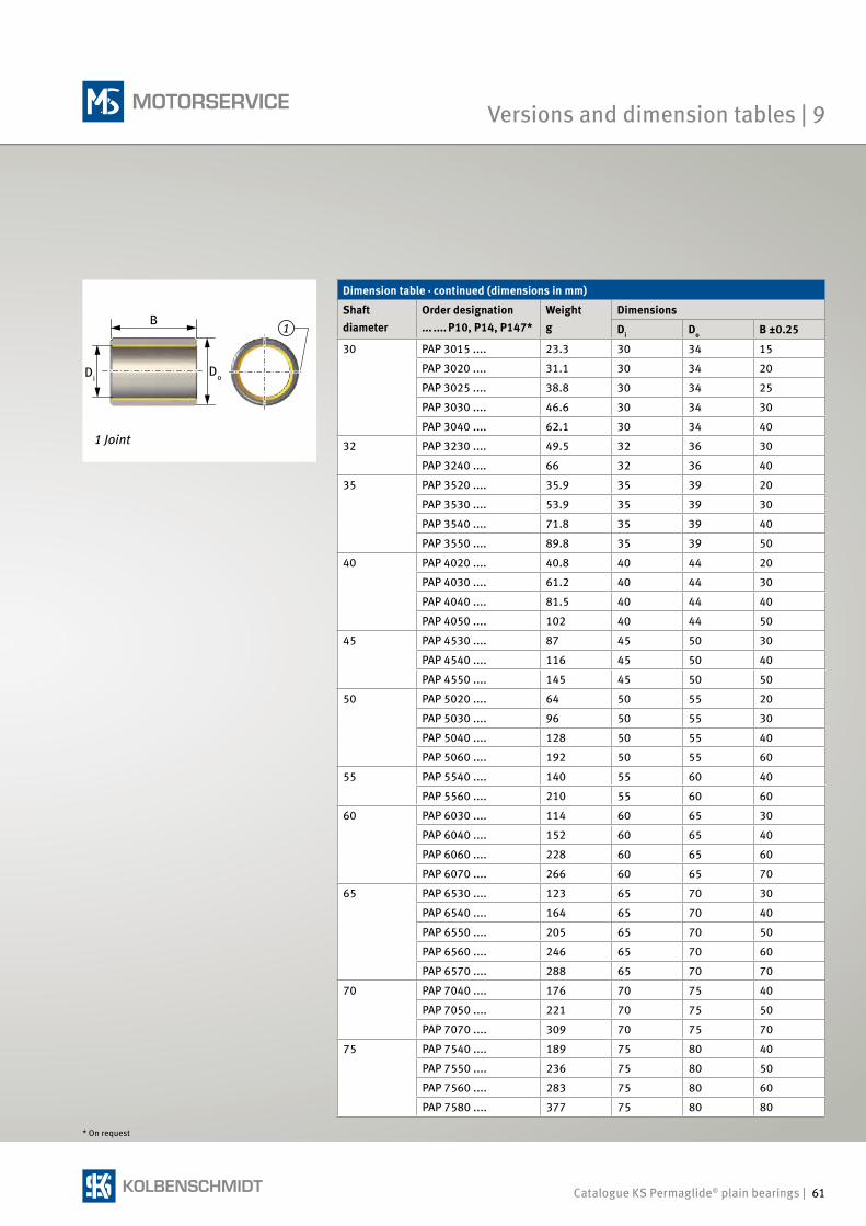
Catalogue KS Permaglide® plain bearings | 61
1
* On request
Dimension table · continued (dimensions in mm)
Shaft diameter
Order designation ... .... P10, P14, P147*
Weight g
Dimensions
Di Do B ±0.25
30 PAP 3015 .... 23.3 30 34 15
PAP 3020 .... 31.1 30 34 20
PAP 3025 .... 38.8 30 34 25
PAP 3030 .... 46.6 30 34 30
PAP 3040 .... 62.1 30 34 40
32 PAP 3230 .... 49.5 32 36 30
PAP 3240 .... 66 32 36 40
35 PAP 3520 .... 35.9 35 39 20
PAP 3530 .... 53.9 35 39 30
PAP 3540 .... 71.8 35 39 40
PAP 3550 .... 89.8 35 39 50
40 PAP 4020 .... 40.8 40 44 20
PAP 4030 .... 61.2 40 44 30
PAP 4040 .... 81.5 40 44 40
PAP 4050 .... 102 40 44 50
45 PAP 4530 .... 87 45 50 30
PAP 4540 .... 116 45 50 40
PAP 4550 .... 145 45 50 50
50 PAP 5020 .... 64 50 55 20
PAP 5030 .... 96 50 55 30
PAP 5040 .... 128 50 55 40
PAP 5060 .... 192 50 55 60
55 PAP 5540 .... 140 55 60 40
PAP 5560 .... 210 55 60 60
60 PAP 6030 .... 114 60 65 30
PAP 6040 .... 152 60 65 40
PAP 6060 .... 228 60 65 60
PAP 6070 .... 266 60 65 70
65 PAP 6530 .... 123 65 70 30
PAP 6540 .... 164 65 70 40
PAP 6550 .... 205 65 70 50
PAP 6560 .... 246 65 70 60
PAP 6570 .... 288 65 70 70
70 PAP 7040 .... 176 70 75 40
PAP 7050 .... 221 70 75 50
PAP 7070 .... 309 70 75 70
75 PAP 7540 .... 189 75 80 40
PAP 7550 .... 236 75 80 50
PAP 7560 .... 283 75 80 60
PAP 7580 .... 377 75 80 80
B
DiDo
1 Joint
Versions and dimension tables | 9
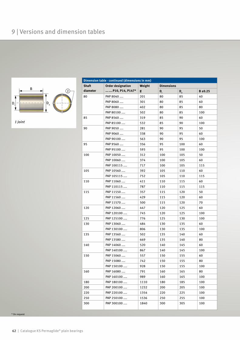
62 | Catalogue KS Permaglide® plain bearings
1
Dimension table · continued (dimensions in mm)
Shaft diameter
Order designation ... .... P10, P14, P147*
Weightg
Dimensions
Di Do B ±0.25
80 PAP 8040 .... 201 80 85 40
PAP 8060 .... 301 80 85 60
PAP 8080 .... 402 80 85 80
PAP 80100 .... 502 80 85 100
85 PAP 8560 .... 319 85 90 60
PAP 85100 .... 532 85 90 100
90 PAP 9050 .... 281 90 95 50
PAP 9060 .... 338 90 95 60
PAP 90100 .... 563 90 95 100
95 PAP 9560 .... 356 95 100 60
PAP 95100 .... 593 95 100 100
100 PAP 10050 .... 312 100 105 50
PAP 10060 .... 374 100 105 60
PAP 100115 .... 717 100 105 115
105 PAP 10560 .... 392 105 110 60
PAP 105115 .... 752 105 110 115
110 PAP 11060 .... 411 110 115 60
PAP 110115 .... 787 110 115 115
115 PAP 11550 .... 357 115 120 50
PAP 11560 .... 429 115 120 60
PAP 11570 .... 500 115 120 70
120 PAP 12060 .... 447 120 125 60
PAP 120100 .... 745 120 125 100
125 PAP 125100 .... 776 125 130 100
130 PAP 13060 .... 484 130 135 60
PAP 130100 .... 806 130 135 100
135 PAP 13560 .... 502 135 140 60
PAP 13580 .... 669 135 140 80
140 PAP 14060 .... 520 140 145 60
PAP 140100 .... 867 140 145 100
150 PAP 15060 .... 557 150 155 60
PAP 15080 .... 742 150 155 80
PAP 150100 .... 928 150 155 100
160 PAP 16080 .... 791 160 165 80
PAP 160100 .... 989 160 165 100
180 PAP 180100 .... 1110 180 185 100
200 PAP 200100 .... 1232 200 205 100
220 PAP 220100 .... 1354 220 225 100
250 PAP 250100 .... 1536 250 255 100
300 PAP 300100 .... 1840 300 305 100
B
DiDo
1 Joint
* On request
9 | Versions and dimension tables
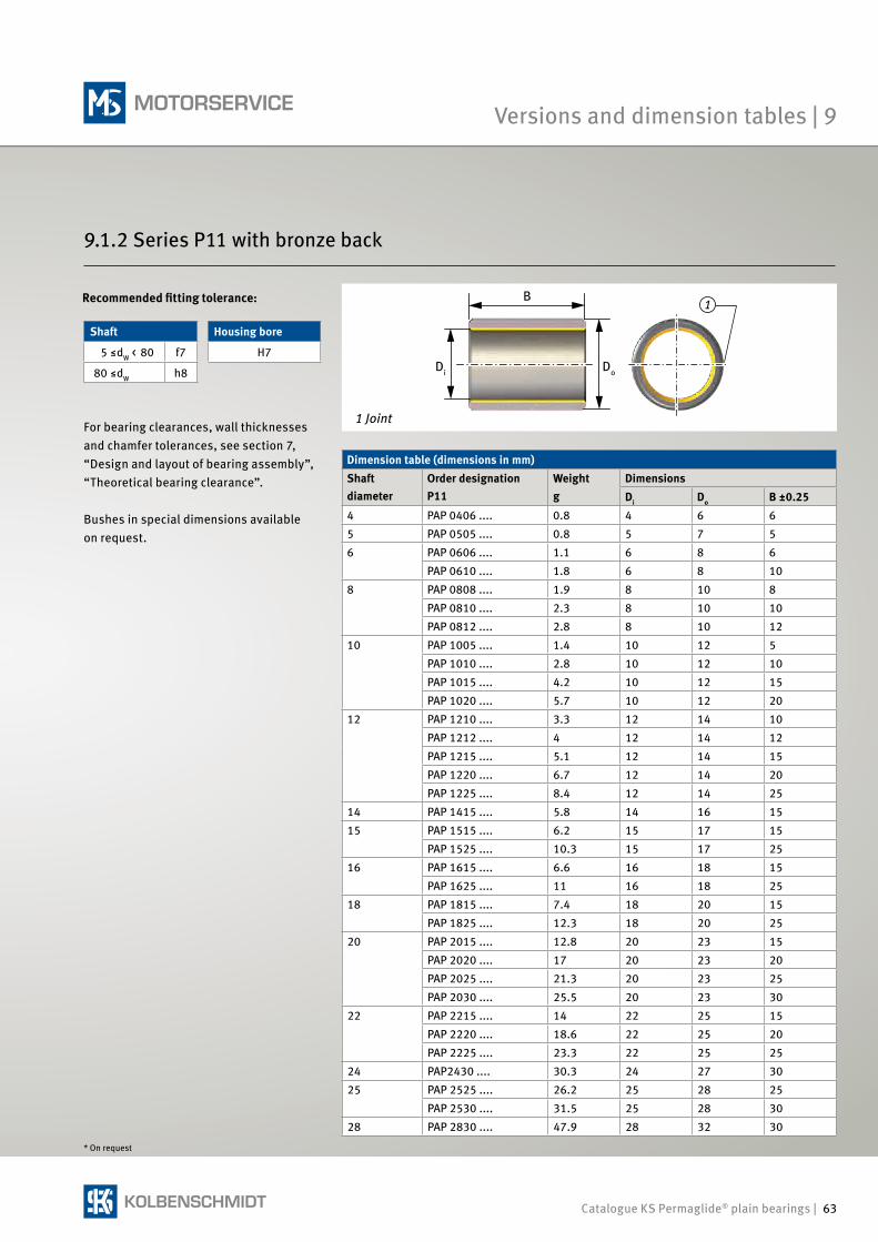
Catalogue KS Permaglide® plain bearings | 63
1
9.1.2 Series P11 with bronze back
Dimension table (dimensions in mm)Shaft diameter
Order designationP11
Weightg
DimensionsDi Do B ±0.25
4 PAP 0406 .... 0.8 4 6 65 PAP 0505 .... 0.8 5 7 56 PAP 0606 .... 1.1 6 8 6
PAP 0610 .... 1.8 6 8 108 PAP 0808 .... 1.9 8 10 8
PAP 0810 .... 2.3 8 10 10PAP 0812 .... 2.8 8 10 12
10 PAP 1005 .... 1.4 10 12 5PAP 1010 .... 2.8 10 12 10PAP 1015 .... 4.2 10 12 15PAP 1020 .... 5.7 10 12 20
12 PAP 1210 .... 3.3 12 14 10PAP 1212 .... 4 12 14 12PAP 1215 .... 5.1 12 14 15PAP 1220 .... 6.7 12 14 20PAP 1225 .... 8.4 12 14 25
14 PAP 1415 .... 5.8 14 16 1515 PAP 1515 .... 6.2 15 17 15
PAP 1525 .... 10.3 15 17 2516 PAP 1615 .... 6.6 16 18 15
PAP 1625 .... 11 16 18 2518 PAP 1815 .... 7.4 18 20 15
PAP 1825 .... 12.3 18 20 2520 PAP 2015 .... 12.8 20 23 15
PAP 2020 .... 17 20 23 20PAP 2025 .... 21.3 20 23 25PAP 2030 .... 25.5 20 23 30
22 PAP 2215 .... 14 22 25 15PAP 2220 .... 18.6 22 25 20PAP 2225 .... 23.3 22 25 25
24 PAP2430 .... 30.3 24 27 3025 PAP 2525 .... 26.2 25 28 25
PAP 2530 .... 31.5 25 28 3028 PAP 2830 .... 47.9 28 32 30
For bearing clearances, wall thicknesses and chamfer tolerances, see section 7, “Design and layout of bearing assembly”, “Theoretical bearing clearance”.
Bushes in special dimensions available on request.
Shaft Housing bore
5 ≤dW < 80 f7 H7
80 ≤dW h8
B
Di Do
1 Joint
Recommended fitting tolerance:
* On request
Versions and dimension tables | 9
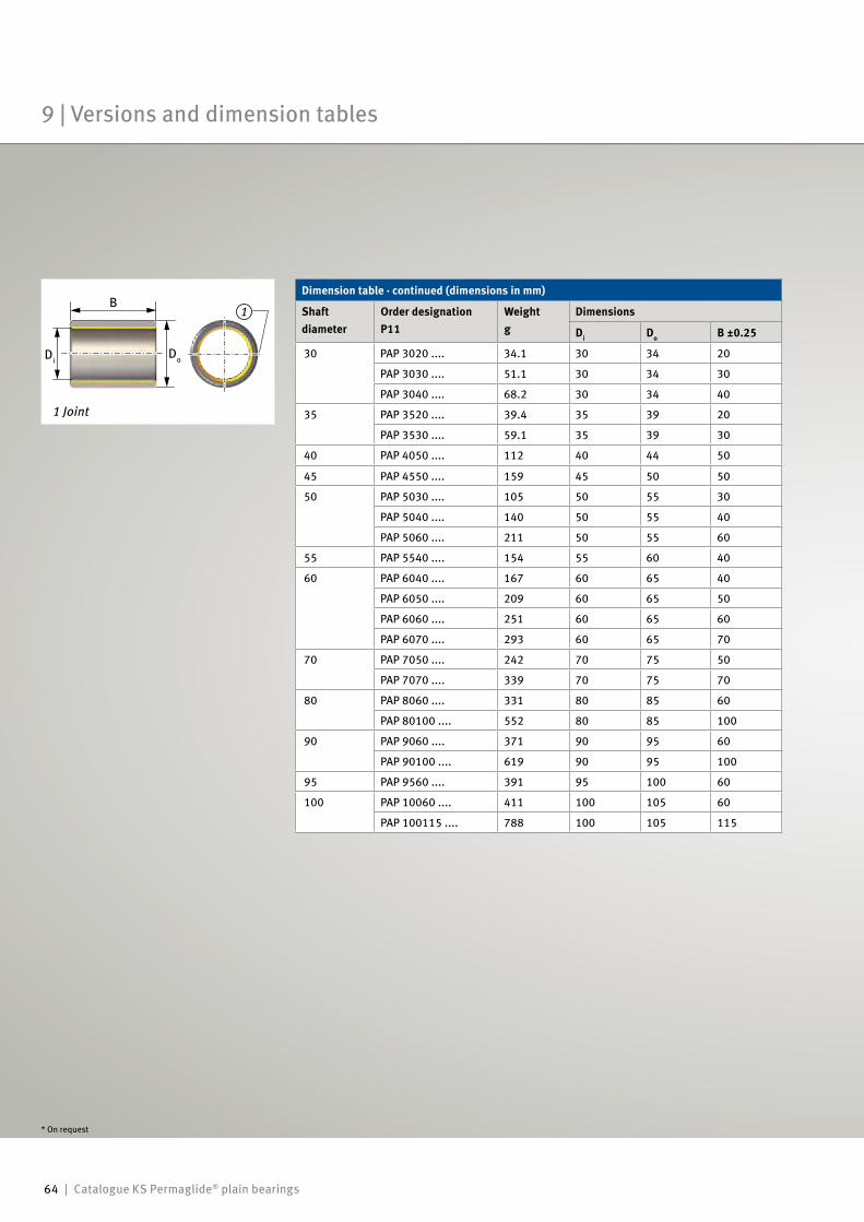
64 | Catalogue KS Permaglide® plain bearings
1
Dimension table · continued (dimensions in mm)
Shaft diameter
Order designationP11
Weightg
Dimensions
Di Do B ±0.25
30 PAP 3020 .... 34.1 30 34 20
PAP 3030 .... 51.1 30 34 30
PAP 3040 .... 68.2 30 34 40
35 PAP 3520 .... 39.4 35 39 20
PAP 3530 .... 59.1 35 39 30
40 PAP 4050 .... 112 40 44 50
45 PAP 4550 .... 159 45 50 50
50 PAP 5030 .... 105 50 55 30
PAP 5040 .... 140 50 55 40
PAP 5060 .... 211 50 55 60
55 PAP 5540 .... 154 55 60 40
60 PAP 6040 .... 167 60 65 40
PAP 6050 .... 209 60 65 50
PAP 6060 .... 251 60 65 60
PAP 6070 .... 293 60 65 70
70 PAP 7050 .... 242 70 75 50
PAP 7070 .... 339 70 75 70
80 PAP 8060 .... 331 80 85 60
PAP 80100 .... 552 80 85 100
90 PAP 9060 .... 371 90 95 60
PAP 90100 .... 619 90 95 100
95 PAP 9560 .... 391 95 100 60
100 PAP 10060 .... 411 100 105 60
PAP 100115 .... 788 100 105 115
B
DiDo
1 Joint
* On request
9 | Versions and dimension tables
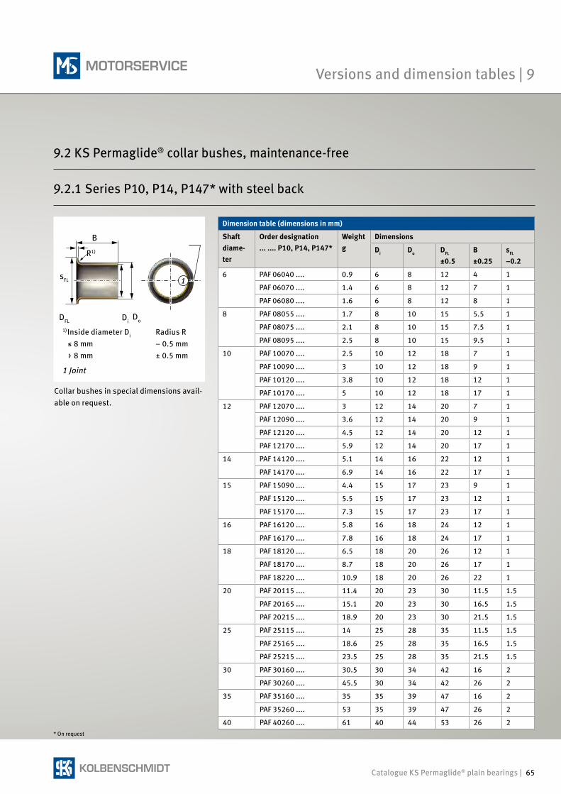
Catalogue KS Permaglide® plain bearings | 65
Collar bushes in special dimensions avail-able on request.
Dimension table (dimensions in mm)
Shaft diame-ter
Order designation ... .... P10, P14, P147*
Weightg
Dimensions
Di Do DFL
±0.5B ±0.25
sFL –0.2
6 PAF 06040 .... 0.9 6 8 12 4 1
PAF 06070 .... 1.4 6 8 12 7 1
PAF 06080 .... 1.6 6 8 12 8 1
8 PAF 08055 .... 1.7 8 10 15 5.5 1
PAF 08075 .... 2.1 8 10 15 7.5 1
PAF 08095 .... 2.5 8 10 15 9.5 1
10 PAF 10070 .... 2.5 10 12 18 7 1
PAF 10090 .... 3 10 12 18 9 1
PAF 10120 .... 3.8 10 12 18 12 1
PAF 10170 .... 5 10 12 18 17 1
12 PAF 12070 .... 3 12 14 20 7 1
PAF 12090 .... 3.6 12 14 20 9 1
PAF 12120 .... 4.5 12 14 20 12 1
PAF 12170 .... 5.9 12 14 20 17 1
14 PAF 14120 .... 5.1 14 16 22 12 1
PAF 14170 .... 6.9 14 16 22 17 1
15 PAF 15090 .... 4.4 15 17 23 9 1
PAF 15120 .... 5.5 15 17 23 12 1
PAF 15170 .... 7.3 15 17 23 17 1
16 PAF 16120 .... 5.8 16 18 24 12 1
PAF 16170 .... 7.8 16 18 24 17 1
18 PAF 18120 .... 6.5 18 20 26 12 1
PAF 18170 .... 8.7 18 20 26 17 1
PAF 18220 .... 10.9 18 20 26 22 1
20 PAF 20115 .... 11.4 20 23 30 11.5 1.5
PAF 20165 .... 15.1 20 23 30 16.5 1.5
PAF 20215 .... 18.9 20 23 30 21.5 1.5
25 PAF 25115 .... 14 25 28 35 11.5 1.5
PAF 25165 .... 18.6 25 28 35 16.5 1.5
PAF 25215 .... 23.5 25 28 35 21.5 1.5
30 PAF 30160 .... 30.5 30 34 42 16 2
PAF 30260 .... 45.5 30 34 42 26 2
35 PAF 35160 .... 35 35 39 47 16 2
PAF 35260 .... 53 35 39 47 26 2
40 PAF 40260 .... 61 40 44 53 26 2
1
B
R1)
sFL
DFL DiDo
1 Joint
Inside diameter Di Radius R≤ 8 mm – 0.5 mm> 8 mm ± 0.5 mm
1)
9.2.1 Series P10, P14, P147* with steel back
* On request
Versions and dimension tables | 9
9.2 KS Permaglide® collar bushes, maintenance-free
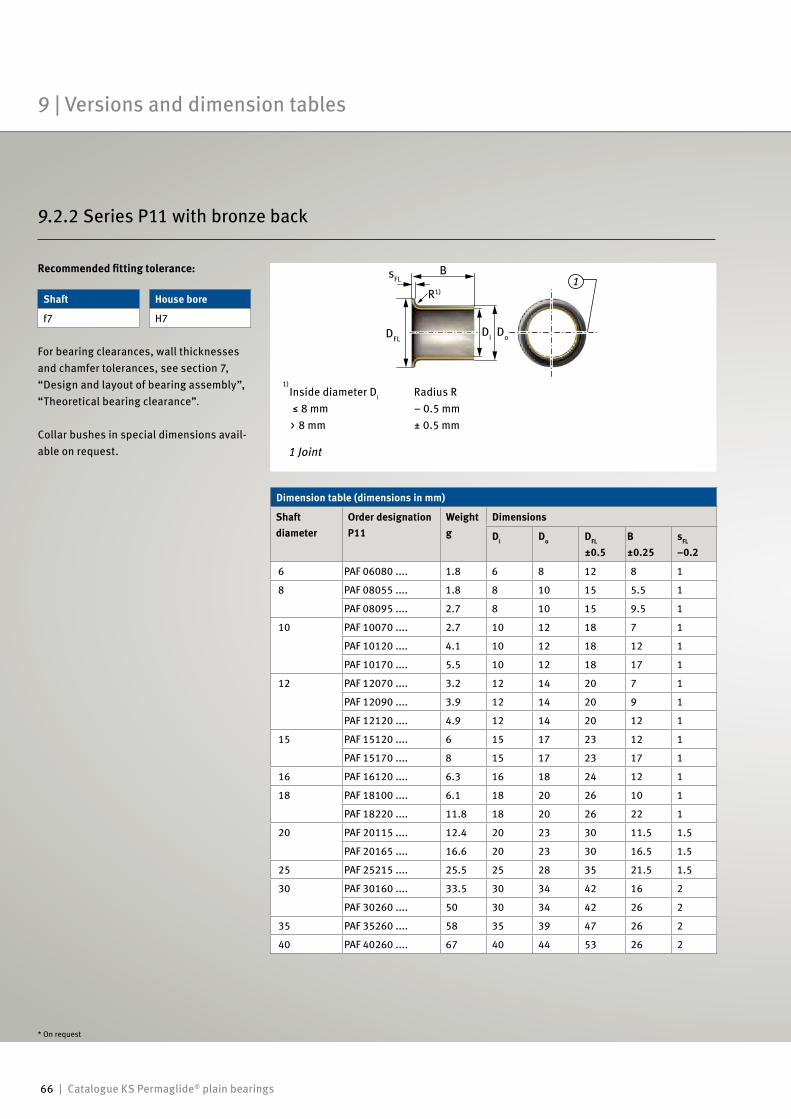
66 | Catalogue KS Permaglide® plain bearings
1
9.2.2 Series P11 with bronze back
For bearing clearances, wall thicknesses and chamfer tolerances, see section 7, “Design and layout of bearing assembly”, “Theoretical bearing clearance”.
Collar bushes in special dimensions avail-able on request.
Shaft House bore
f7 H7
Dimension table (dimensions in mm)
Shaft diameter
Order designationP11
Weightg
Dimensions
Di Do DFL
±0.5B ±0.25
sFL –0.2
6 PAF 06080 .... 1.8 6 8 12 8 1
8 PAF 08055 .... 1.8 8 10 15 5.5 1
PAF 08095 .... 2.7 8 10 15 9.5 1
10 PAF 10070 .... 2.7 10 12 18 7 1
PAF 10120 .... 4.1 10 12 18 12 1
PAF 10170 .... 5.5 10 12 18 17 1
12 PAF 12070 .... 3.2 12 14 20 7 1
PAF 12090 .... 3.9 12 14 20 9 1
PAF 12120 .... 4.9 12 14 20 12 1
15 PAF 15120 .... 6 15 17 23 12 1
PAF 15170 .... 8 15 17 23 17 1
16 PAF 16120 .... 6.3 16 18 24 12 1
18 PAF 18100 .... 6.1 18 20 26 10 1
PAF 18220 .... 11.8 18 20 26 22 1
20 PAF 20115 .... 12.4 20 23 30 11.5 1.5
PAF 20165 .... 16.6 20 23 30 16.5 1.5
25 PAF 25215 .... 25.5 25 28 35 21.5 1.5
30 PAF 30160 .... 33.5 30 34 42 16 2
PAF 30260 .... 50 30 34 42 26 2
35 PAF 35260 .... 58 35 39 47 26 2
40 PAF 40260 .... 67 40 44 53 26 2
B
R1)
sFL
DFLDi Do
Inside diameter Di Radius R ≤ 8 mm – 0.5 mm> 8 mm ± 0.5 mm
1 Joint
1)
Recommended fitting tolerance:
* On request
9 | Versions and dimension tables
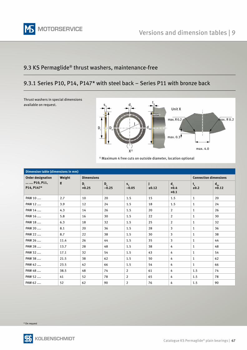
Catalogue KS Permaglide® plain bearings | 67
9.3.1 Series P10, P14, P147* with steel back – Series P11 with bronze back
Dimension table (dimensions in mm)
Order designation... .... P10, P11, P14, P147*
Weightg
Dimensions Connection dimensions
Di+0.25
Do–0.25
s3–0.05
J±0.12
d1+0.4+0.1
ta ±0.2
d6a+0.12
PAW 10 .... 2.7 10 20 1.5 15 1.5 1 20
PAW 12 .... 3.9 12 24 1.5 18 1.5 1 24
PAW 14 .... 4.3 14 26 1.5 20 2 1 26
PAW 16 .... 5.8 16 30 1.5 22 2 1 30
PAW 18 .... 6.3 18 32 1.5 25 2 1 32
PAW 20 .... 8.1 20 36 1.5 28 3 1 36
PAW 22 .... 8.7 22 38 1.5 30 3 1 38
PAW 26 .... 11.4 26 44 1.5 35 3 1 44
PAW 28 .... 13.7 28 48 1.5 38 4 1 48
PAW 32 .... 17.1 32 54 1.5 43 4 1 54
PAW 38 .... 21.5 38 62 1.5 50 4 1 62
PAW 42 .... 23.5 42 66 1.5 54 4 1 66
PAW 48 .... 38.5 48 74 2 61 4 1.5 74
PAW 52 .... 41 52 78 2 65 4 1.5 78
PAW 62 .... 52 62 90 2 76 4 1.5 90
Di Do
s3
Jd6a
tad1Unit X
max. R 0.2
max. 0.3
max. 4.0
max. R 0.2
1) Maximum 4 free cuts on outside diameter, location optional
Thrust washers in special dimensions available on request.
* On request
Versions and dimension tables | 9
X1)
9.3 KS Permaglide® thrust washers, maintenance-free
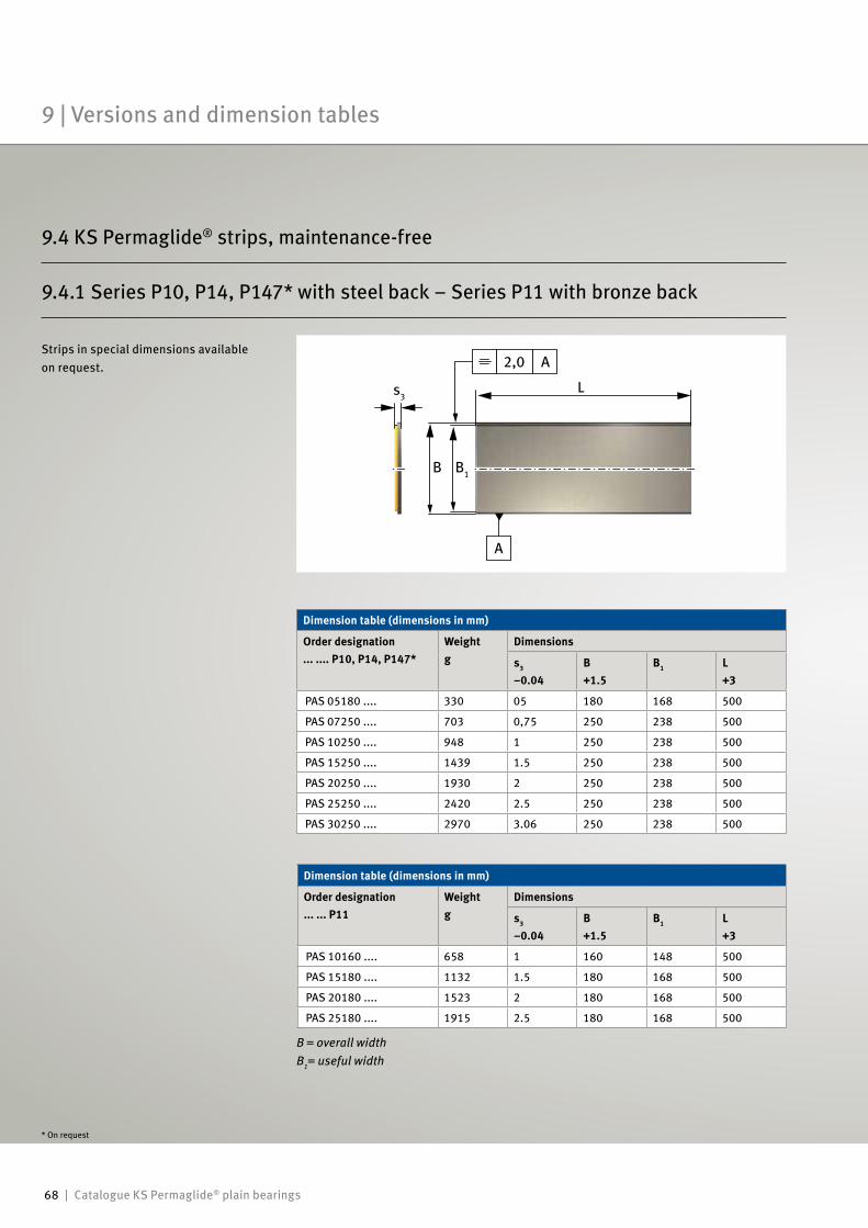
68 | Catalogue KS Permaglide® plain bearings
2,0
s3
A
A
B B1
L
Strips in special dimensions available on request.
B = overall widthB1= useful width
Dimension table (dimensions in mm)
Order designation... ... P11
Weightg
Dimensions
s3
–0.04B+1.5
B1 L+3
PAS 10160 .... 658 1 160 148 500
PAS 15180 .... 1132 1.5 180 168 500
PAS 20180 .... 1523 2 180 168 500
PAS 25180 .... 1915 2.5 180 168 500
Dimension table (dimensions in mm)
Order designation... .... P10, P14, P147*
Weightg
Dimensions
s3
–0.04B+1.5
B1 L+3
PAS 05180 .... 330 05 180 168 500
PAS 07250 .... 703 0,75 250 238 500
PAS 10250 .... 948 1 250 238 500
PAS 15250 .... 1439 1.5 250 238 500
PAS 20250 .... 1930 2 250 238 500
PAS 25250 .... 2420 2.5 250 238 500
PAS 30250 .... 2970 3.06 250 238 500
9.4.1 Series P10, P14, P147* with steel back – Series P11 with bronze back
* On request
9 | Versions and dimension tables
9.4 KS Permaglide® strips, maintenance-free
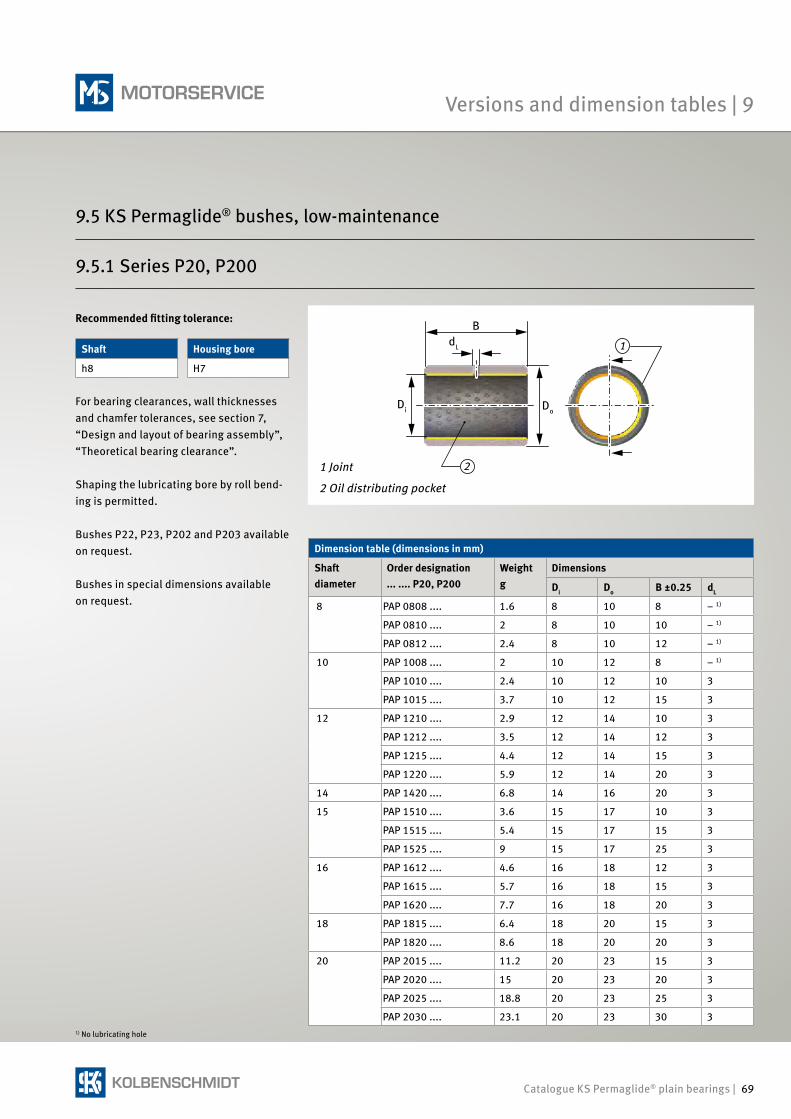
Catalogue KS Permaglide® plain bearings | 69
1
2
9.5.1 Series P20, P200
For bearing clearances, wall thicknesses and chamfer tolerances, see section 7, “Design and layout of bearing assembly”, “Theoretical bearing clearance”.
Shaping the lubricating bore by roll bend-ing is permitted.
Bushes P22, P23, P202 and P203 available on request.
Bushes in special dimensions available on request.
Shaft Housing bore
h8 H7
1) No lubricating hole
B
Di
dL
Do
1 Joint
2 Oil distributing pocket
Dimension table (dimensions in mm)
Shaft diameter
Order designation ... .... P20, P200
Weightg
Dimensions
Di Do B ±0.25 dL
8 PAP 0808 .... 1.6 8 10 8 – 1)
PAP 0810 .... 2 8 10 10 – 1)
PAP 0812 .... 2.4 8 10 12 – 1)
10 PAP 1008 .... 2 10 12 8 – 1)
PAP 1010 .... 2.4 10 12 10 3
PAP 1015 .... 3.7 10 12 15 3
12 PAP 1210 .... 2.9 12 14 10 3
PAP 1212 .... 3.5 12 14 12 3
PAP 1215 .... 4.4 12 14 15 3
PAP 1220 .... 5.9 12 14 20 3
14 PAP 1420 .... 6.8 14 16 20 3
15 PAP 1510 .... 3.6 15 17 10 3
PAP 1515 .... 5.4 15 17 15 3
PAP 1525 .... 9 15 17 25 3
16 PAP 1612 .... 4.6 16 18 12 3
PAP 1615 .... 5.7 16 18 15 3
PAP 1620 .... 7.7 16 18 20 3
18 PAP 1815 .... 6.4 18 20 15 3
PAP 1820 .... 8.6 18 20 20 3
20 PAP 2015 .... 11.2 20 23 15 3
PAP 2020 .... 15 20 23 20 3
PAP 2025 .... 18.8 20 23 25 3
PAP 2030 .... 23.1 20 23 30 3
Recommended fitting tolerance:
Versions and dimension tables | 9
9.5 KS Permaglide® bushes, low-maintenance
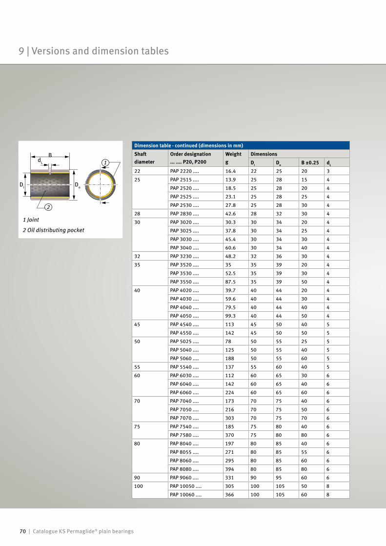
70 | Catalogue KS Permaglide® plain bearings
1
2
Dimension table · continued (dimensions in mm)
Shaft diameter
Order designation ... .... P20, P200
Weightg
Dimensions
Di Do B ±0.25 dL
22 PAP 2220 .... 16.4 22 25 20 3
25 PAP 2515 .... 13.9 25 28 15 4
PAP 2520 .... 18.5 25 28 20 4
PAP 2525 .... 23.1 25 28 25 4
PAP 2530 .... 27.8 25 28 30 4
28 PAP 2830 .... 42.6 28 32 30 4
30 PAP 3020 .... 30.3 30 34 20 4
PAP 3025 .... 37.8 30 34 25 4
PAP 3030 .... 45.4 30 34 30 4
PAP 3040 .... 60.6 30 34 40 4
32 PAP 3230 .... 48.2 32 36 30 4
35 PAP 3520 .... 35 35 39 20 4
PAP 3530 .... 52.5 35 39 30 4
PAP 3550 .... 87.5 35 39 50 4
40 PAP 4020 .... 39.7 40 44 20 4
PAP 4030 .... 59.6 40 44 30 4
PAP 4040 .... 79.5 40 44 40 4
PAP 4050 .... 99.3 40 44 50 4
45 PAP 4540 .... 113 45 50 40 5
PAP 4550 .... 142 45 50 50 5
50 PAP 5025 .... 78 50 55 25 5
PAP 5040 .... 125 50 55 40 5
PAP 5060 .... 188 50 55 60 5
55 PAP 5540 .... 137 55 60 40 5
60 PAP 6030 .... 112 60 65 30 6
PAP 6040 .... 142 60 65 40 6
PAP 6060 .... 224 60 65 60 6
70 PAP 7040 .... 173 70 75 40 6
PAP 7050 .... 216 70 75 50 6
PAP 7070 .... 303 70 75 70 6
75 PAP 7540 .... 185 75 80 40 6
PAP 7580 .... 370 75 80 80 6
80 PAP 8040 .... 197 80 85 40 6
PAP 8055 .... 271 80 85 55 6
PAP 8060 .... 295 80 85 60 6
PAP 8080 .... 394 80 85 80 6
90 PAP 9060 .... 331 90 95 60 6
100 PAP 10050 .... 305 100 105 50 8
PAP 10060 .... 366 100 105 60 8
B
Di
dL
Do
1 Joint
2 Oil distributing pocket
9 | Versions and dimension tables
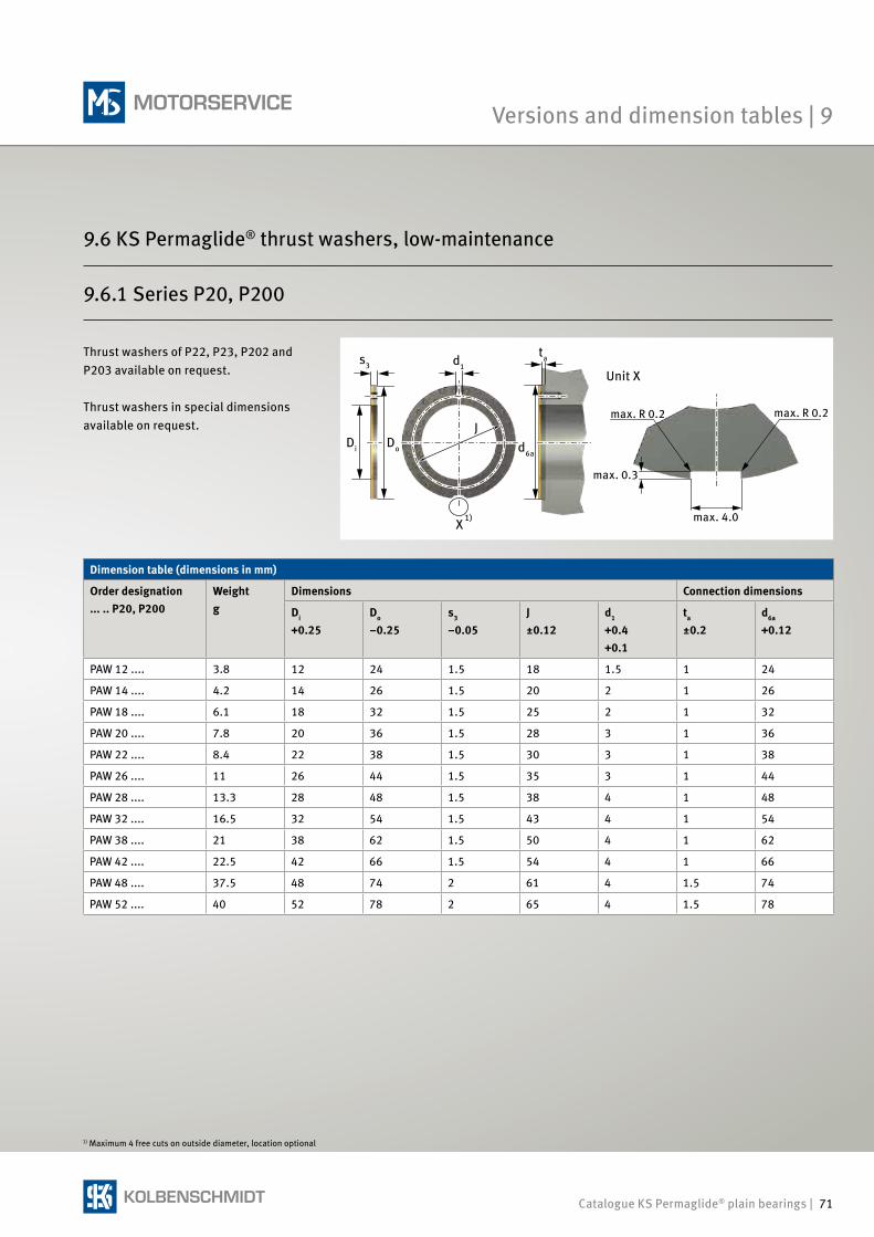
Catalogue KS Permaglide® plain bearings | 71
Dimension table (dimensions in mm)
Order designation... .. P20, P200
Weightg
Dimensions Connection dimensions
Di
+0.25Do
–0.25s3
–0.05J±0.12
d1
+0.4+0.1
ta ±0.2
d6a
+0.12
PAW 12 .... 3.8 12 24 1.5 18 1.5 1 24
PAW 14 .... 4.2 14 26 1.5 20 2 1 26
PAW 18 .... 6.1 18 32 1.5 25 2 1 32
PAW 20 .... 7.8 20 36 1.5 28 3 1 36
PAW 22 .... 8.4 22 38 1.5 30 3 1 38
PAW 26 .... 11 26 44 1.5 35 3 1 44
PAW 28 .... 13.3 28 48 1.5 38 4 1 48
PAW 32 .... 16.5 32 54 1.5 43 4 1 54
PAW 38 .... 21 38 62 1.5 50 4 1 62
PAW 42 .... 22.5 42 66 1.5 54 4 1 66
PAW 48 .... 37.5 48 74 2 61 4 1.5 74
PAW 52 .... 40 52 78 2 65 4 1.5 78
9.6.1 Series P20, P200
1) Maximum 4 free cuts on outside diameter, location optional
Di Do
s3
Jd6a
tad1
X1)
Unit X
max. R 0.2
max. 0.3
max. 4.0
max. R 0.2
Thrust washers of P22, P23, P202 and P203 available on request.
Thrust washers in special dimensions available on request.
Versions and dimension tables | 9
9.6 KS Permaglide® thrust washers, low-maintenance
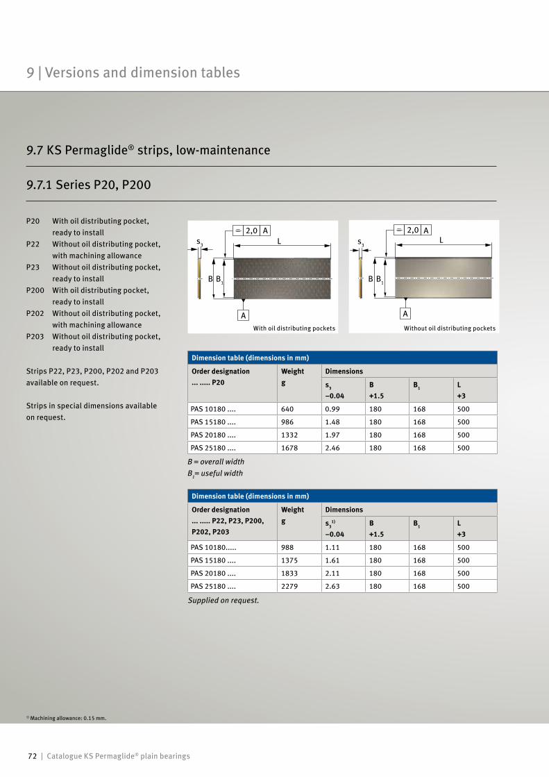
72 | Catalogue KS Permaglide® plain bearings
9.7.1 Series P20, P200
B = overall widthB1= useful width
1) Machining allowance: 0.15 mm.
Dimension table (dimensions in mm)
Order designation... ..... P22, P23, P200, P202, P203
Weightg
Dimensions
s31)
–0.04B+1.5
B1 L+3
PAS 10180..... 988 1.11 180 168 500
PAS 15180 .... 1375 1.61 180 168 500
PAS 20180 .... 1833 2.11 180 168 500
PAS 25180 .... 2279 2.63 180 168 500
Dimension table (dimensions in mm)
Order designation... ..... P20
Weightg
Dimensions
s3
–0.04B+1.5
B1 L+3
PAS 10180 .... 640 0.99 180 168 500
PAS 15180 .... 986 1.48 180 168 500
PAS 20180 .... 1332 1.97 180 168 500
PAS 25180 .... 1678 2.46 180 168 500
Supplied on request.
s3
2,0 2,0 A
A
A
A
B B1
L
Without oil distributing pockets
B
Ls3
B1
With oil distributing pockets
P20 With oil distributing pocket, ready to installP22 Without oil distributing pocket, with machining allowanceP23 Without oil distributing pocket, ready to installP200 With oil distributing pocket, ready to installP202 Without oil distributing pocket, with machining allowanceP203 Without oil distributing pocket, ready to install
Strips P22, P23, P200, P202 and P203 available on request.
Strips in special dimensions available on request.
9 | Versions and dimension tables
9.7 KS Permaglide® strips, low-maintenance
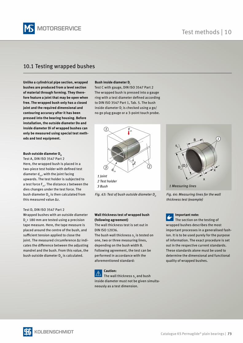
Catalogue KS Permaglide® plain bearings | 73
1
23
Test methods | 10
Fig. 64: Measuring lines for the wall thickness test (example)
Unlike a cylindrical pipe section, wrapped bushes are produced from a level section of material through forming. They there- fore feature a joint that may be open when free. The wrapped bush only has a closed joint and the required dimensional and contouring accuracy after it has been pressed into the bearing housing. Before installation, the outside diameter Do and inside diameter Di of wrapped bushes can only be measured using special test meth-ods and test equipment.
Bush outside diameter DO
Test A, DIN ISO 3547 Part 2Here, the wrapped bush is placed in a two-piece test holder with defined test diameter dch, with the joint facing upwards. The test holder is subjected to a test force Fch. The distance z between the dies changes under the test force. The bush diameter DO is then calculated from this measured value Δz.
Test D, DIN ISO 3547 Part 2Wrapped bushes with an outside diameter Do> 180 mm are tested using a precision tape measure. Here, the tape measure is placed around the centre of the bush, and sufficient tension applied to close the joint. The measured circumference Δz indi-cates the difference between the adjusting mandrel and the bush. From this value, the bush outside diameter DO is calculated.
Bush inside diameter Di
Test C with gauge, DIN ISO 3547 Part 2The wrapped bush is pressed into a gauge ring with a test diameter defined according to DIN ISO 3547 Part 1, Tab. 5. The bush inside diameter Di is checked using a go/no go plug gauge or a 3-point touch probe.
Important note:The section on the testing of
wrapped bushes describes the most important processes in a generalised fash-ion. It is to be used purely for the purpose of information. The exact procedure is set out in the respective current standards. These standards alone must be used to determine the dimensional and functional quality of wrapped bushes.
Wall thickness test of wrapped bush (following agreement)The wall thickness test is set out in DIN ISO 12036.The bush wall thickness s3 is tested on one, two or three measuring lines, depending on the bush width B.Following agreement, the test can be performed in accordance with the aforementioned standard:
Caution:The wall thickness s3 and bush
inside diameter must not be given simulta-neously as a test dimension.
Fig. 63: Test of bush outside diameter DO
1 Joint2 Test holder3 Bush
dch
Fch
Z
1B
(Di)Do
s3
x
x
1 Measuring lines
10.1 Testing wrapped bushes
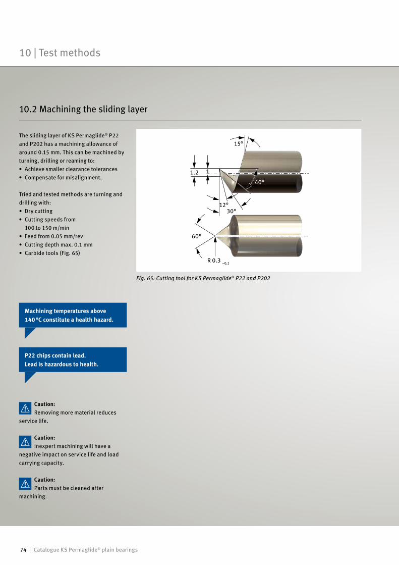
74 | Catalogue KS Permaglide® plain bearings
10 | Test methods
The sliding layer of KS Permaglide® P22 and P202 has a machining allowance of around 0.15 mm. This can be machined by turning, drilling or reaming to:• Achieve smaller clearance tolerances• Compensate for misalignment.
Tried and tested methods are turning and drilling with:• Dry cutting• Cutting speeds from 100 to 150 m/min• Feed from 0.05 mm/rev• Cutting depth max. 0.1 mm• Carbide tools (Fig. 65)
Fig. 65: Cutting tool for KS Permaglide® P22 and P202
15°
12°30°
40°
60°
1.2 1
R 0.3 –0,1
Caution:Parts must be cleaned after
machining.
Caution:Inexpert machining will have a
negative impact on service life and load carrying capacity.
Caution:Removing more material reduces
service life.
Machining temperatures above 140 °C constitute a health hazard.
P22 chips contain lead. Lead is hazardous to health.
10.2 Machining the sliding layer
Catalogue KS Permaglide® plain bearings | 75
Delivery condition • Packed in a bag in a cardboard box, or• Packed in a cardboard box.
StorageKS Permaglide® plain bearings should be stored:• In a dry, clean place• At a constant temperature, as far as
possible• At a relative humidity of max. 65 %.
In your own interests, please observe leg-islation and other regulations concerning
• Protection of the environment• Occupational health & safety and similar
issues.
References/1/ Damm, Höne, Reinicke, Skiadas: Gleitlager im Automobil. Moderne Industrie publishing house,
Volume 322, 2009
/2/ Berger: Untersuchungen an wartungsfreien Verbundgleitlagern. Shaker publishing house, Aachen,
2000
Caution:Keep packaging closed, where pos-
sible. Only remove KS Permaglide® plain bearings from their original packaging immediately before installation.
Further reading:Broichhausen:Schadenskunde, Analyse und Vermeidung von Schäden.Hanser publishing house, Munich, Vienna, 1985
Stork:Lebensdauervorhersage wartungsfreier, dynamisch belasteter Verbundgleitlager mit Hilfe neuronaler NetzeShaker publishing house, Aachen, 2003
Delivery condition, Storage
Environmental issues, health & safety
References

KS Permaglide® Partner:
50 003 863-02 – 11/14 EN© MS Motorservice International GmbH
OriginalKS PERMAGLIDE®
Plain Bearings