ksa fax tel butterfly valves - jytt-intl.comcert no. 0062 kab-qc-30 iso 9001 cert no. qms-0549 ksa...
TRANSCRIPT
Cert No. 0062 KAB-QC-30 ISO 9001Cert No. QMS-0549
KSABUTTERFLY VALVES
CO., LTD.HEAD OFFICE #75-8, MORA-DONG, SASANG-GU, BUSAN, KOREA TEL +82-51-305-3770 FAX +82-51-305-3737
INTERNET ADDRESS http://www.dkvalve.com
E-MAIL ADDRESS [email protected] | [email protected]
DK카다로그최종 2009.4.4 3:22 PM 페이지1
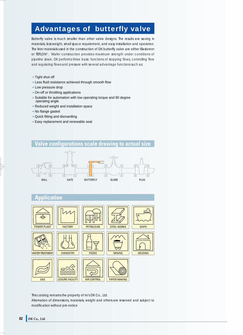
Advantages of butterfly valve IndexButterfly valve is much smaller than other valve designs. The results are saving inmaterials, less weight, small space requirement, and easy installation and operation.The liner materials used in the construction of DK butterfly valve are either Elastomeror TEFLONⓇ. Wafer construction provides maximum strength under conditions ofpipeline strain. DK performs three basic functions of stopping flows, controlling flowand regulating flows and pressure with several advantage functions such as;
ContentsConcentric rubber lined butterfly valve
2 piece split body PTFE lined butterfly valve
Double eccentric High Performance butterfly valve
Triple eccentric High Performance butterfly valve
Dual plate check valve
Engineering data
04
12
14
17
20
22
Valve configurations scale drawing to actual size
Application
This catalog remains the property of m/s DK Co., Ltd.Alternation of dimensions, materials, weight and others are reserved and subject tomodification without pre-notice
•Tight shut off •Less fluid resistance achieved through smooth flow•Low pressure drop•On-off or throttling applications•Suitable for automation with low operating torque and 90 degree
operating angle•Reduced weight and installation space •No flange gasket•Quick fitting and dismantling•Easy replacement and renewable seat
DK Co., Ltd.02
BALL GATE BUTTERFLY GLOBE PLUG
BL301Wafer, Lever OpSize : 40~300mm
(1½″~12″)
BG301Wafer, Gear OpSize : 200~1000mm
(8″~40″)
BL302Full Lug, Lever OpSize : 40~300mm
(1½″~12″)
BG302Full Lug, Gear OpSize : 40~1000mm
(1½″~40″)
BL303Flange, Lever OpSize : 40~300mm
(1½″~12″)
BG303Flange, Gear OpSize : 40~1000mm
(1½″~40″)
BL301EHigh PerformanceWafer, Lever OpSize : 50~150mm
(2″~6″)
BG301EHigh PerformanceEccentric, Gear OpSize : 50~1000mm
(2″~40″)
BL301TWafer Teflon LinedLever OpSize : 40~150mm
(1½″~6″)
BG301TWafer Teflon Lined Gear OpSize : 200~800mm
(8″~32″)
BE301Wafer, Pneumatic OpSize : 40~1000mm
(1½″~40″)
BP301Wafer, Electric OpSize : 40~1000mm
(1½″~40″)
BC301Wafer Center wheel OpSize : 40~300mm
(1½″~12″)
BW301Chain wheel OpGear OpSize : 40~1000mm
(1½″~40″)
DK Co., Ltd. 03
POWER PLANT FACTORY STEEL WORKSPETROLEUM SHIPS
WATER TREATMENT CHEMISTRY MININGFOODS HOUSING
GAS LEISURE FACILITY PAPER MAKINGAIR CONTROL
DK카다로그최종 2009.4.4 3:22 PM 페이지3

StandardAccording to ISO 5752 - BS 5155 - MSS SP 67 - API 609
Product range40mm up to 1000mm(1½″~40″)
Pressure rangeDesigned for maximum working pressure of 16bar (240psi)
Flange connectionsThe shape of valve body has been so designed as toallow flange bolt alignment onto following standards.Wafer type valve has been successfully developed to fitmulti functional application onto either connectionstandard in the same configuration, mainly
ISO PN 6, 10, 16, 20ANSI B 16.1 CL.BS 4504 PN6, PN10, PN16AS 2109 Table D and EMSS SP 44 CL. 150ANSI B 16.5 CL. 150BS 10 Table D and EJIS B 2210 5K, 10K, 16K and 20K
OperatingHand lever with notch plateManual worm gearWith locking deviceElectric/Pneumatic actuatorHydraulic actuatorChainwheel gear box
TestingAPI598MSS SP 61, ANSI B 16.104
Mounting plate in accordance with ISO standard
Heavy duty top bushing adsorbs side thrust load(PTFE optional)
Piping alignment Flange bolt alignment andinstallation suit for multi-national standard such asJIS, DIN, ANSI and BS flange standard
Liner Retained resilient seat to valve enableseasy replacement and isolates the body and stemfrom the flow. Special design of built-in O-ringprovides positive flange sealling with no pipelinegasket required.
Sealing Hub seal is provided by preloadedcontact between flatted seat surface andspherically machined and polished disc positions
Body Face to face dimension is in accordancewith API and ISO standard.
Disc edge Spherically machined and polisheddisc edge provides full concentric sealing, lowerlever torque, longer seat life and positive shut-offclosed at both directions.
0504
DK DK
Leak-tightness at Line stream, shaft passages and the atmosphere Specifications
Body
Disc
Stem
Seat
Packing
Gland
·Cast iron·Ductile iron·Carbon steel·Stainless steel·Bronze
·Ductile iron·Stainless steel·Aluminum bronze·Coated
·Stainless steel·Stainless steel·Stainless steel·Stainless steel·K-Monel
Elastomer·EPDM·NBR·Viton·Silicon·Neoprene
·EPDM·NBR·Viton
·PP
ASTM A 126 Cl. BASTM A 536 Gr 65-45-12ASTM A 216 WCBASTM A 351 Gr CF8-CF8MASTM B 62
ASTM A 536 Gr 65-45-12ASTM A 351 Gr CF8-CF8MASTM B 148 Cl. C95500EPDM, Viton, Buna-N, etc
ASTM A 276 304ASTM A 276 410ASTM A 276 31617-4PH ASTM A 564 TYPE 630ASTM B 164
Working temperature-10℃ ~ +180℃-10℃ ~ +170℃-20℃ ~ +150℃-20℃ ~ +120℃-10℃ ~ +170℃
Materials
A perfect zero leakage seal at bi-direction is obtained by the compression of the inner between the valve body and the edge ofthe disc. A perfect zero leakage seal is provided by means of flatted liner area around both up and down shaft passages and thespherically machined disc. Since the seat stem hole is smaller than the stem diameter, there is a compression fit forming asecondary seal. The seal insures that no fiuid will leak to atmosphere.
DK Co., Ltd.DK Co., Ltd.
DK카다로그최종 2009.4.4 3:22 PM 페이지5
DK DK
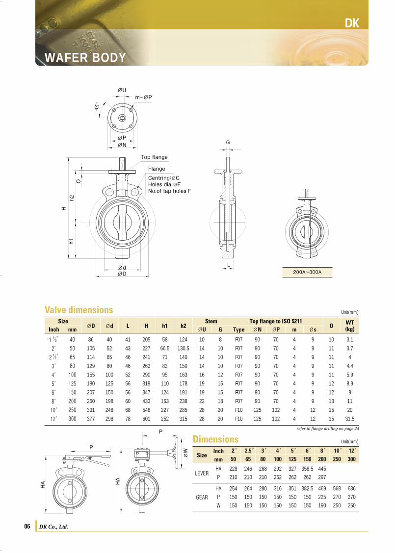
Valve dimensionsSize
ØD Ød L H h1 h2Stem Top flange to ISO 5211
O WT(kg)Inch
1 ½″
2″
2½″
3″
4″
5″
6″
8″
10″
12″
40
50
65
80
100
125
150
200
250
300
86
105
114
129
155
180
207
260
331
377
40
52
65
80
100
125
150
198
248
298
41
43
46
46
52
56
56
60
68
78
205
227
241
263
290
319
347
433
546
601
58
66.5
71
83
95
110
124
163
227
252
124
130.5
140
150
163
178
191
238
285
315
10
14
14
14
16
19
19
22
28
28
8
10
10
10
12
15
15
18
20
20
F07
F07
F07
F07
F07
F07
F07
F07
F10
F10
90
90
90
90
90
90
90
90
125
125
70
70
70
70
70
70
70
70
102
102
4
4
4
4
4
4
4
4
4
4
9
9
9
9
9
9
9
9
12
12
10
11
11
11
11
12
12
13
15
15
3.1
3.7
4
4.4
5.9
8.9
9
11
20
31.5
Unit(mm)
refer to flange drilling on page 24
Unit(mm)
refer to flange drilling on page 24
ØU G Type ØN ØP m Øsmm
0706
WAFER BODYWAFER BODY
DimensionsSize
2″50
2.5″65
3″80
4″100
5″125
6″150
8″200
10″250
12″300
LEVERHAP
228210
246210
268210
292262
327262
358.5262
445297
GEAR
HAPW
254150150
264150150
280150150
316150150
351150150
382.5150150
469225190
568270250
636270250
Inchmm
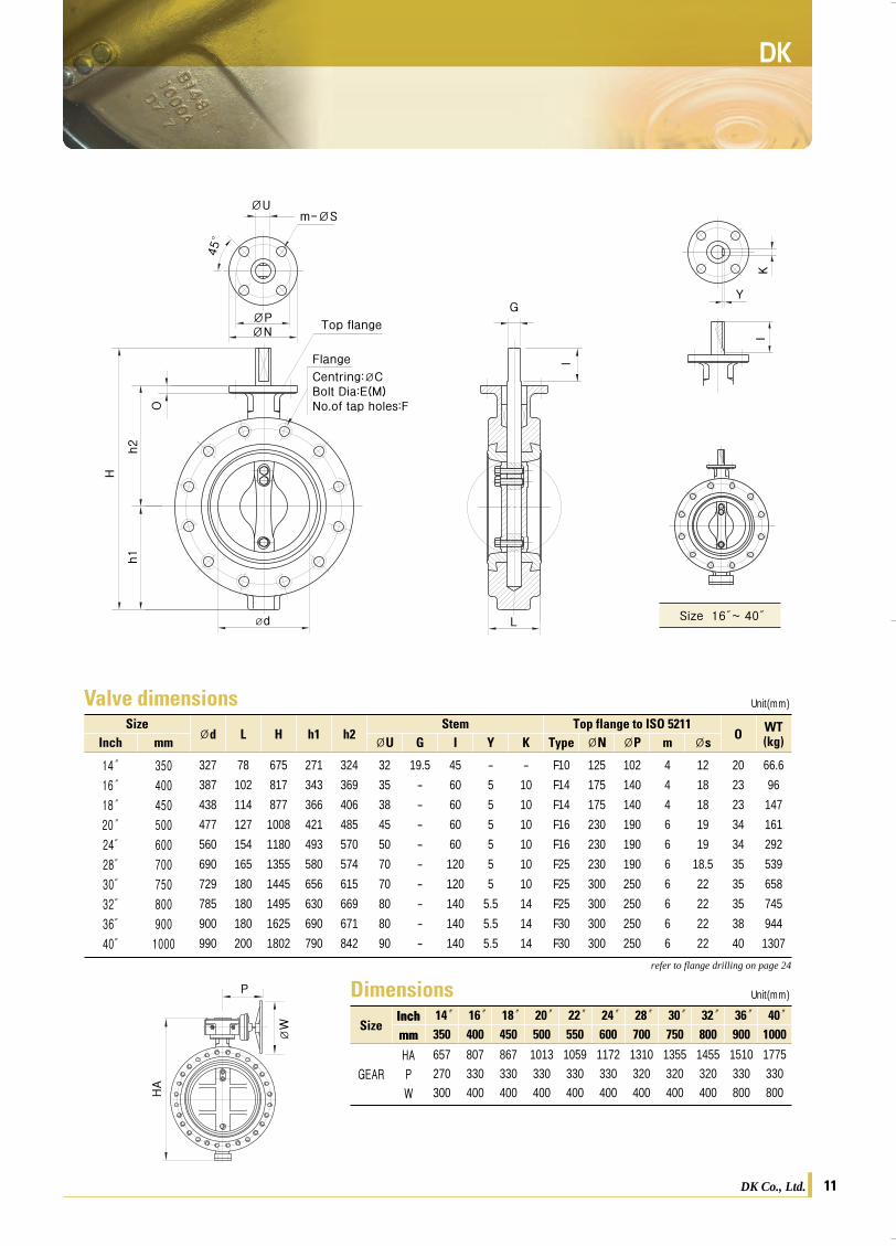
Valve dimensionsSize
ØD Ød L H h1 h2Stem Top flange to ISO 5211
OWT(kg)Inch
14″
16″
18″
20″
24″
28″
30″
32″
36″
40″
350
400
450
500
600
700
750
800
900
1000
416
475
535
590
695
800
857
920
1020
1125
327
387
438
477
560
690
729
785
900
990
78
102
114
127
154
165
180
180
180
200
675
817
877
1008
1180
1355
1445
1495
1625
1802
271
343
366
421
493
580
656
630
690
790
324
369
406
485
570
574
615
669
671
842
32
35
38
45
50
70
70
80
80
90
19.5
-
-
-
-
-
-
-
-
-
45
60
60
60
60
120
120
140
140
140
-
5
5
5
5
5
5
5.5
5.5
5.5
-
10
10
10
10
10
10
14
14
14
F10
F14
F14
F16
F16
F25
F25
F25
F30
F30
125
175
175
230
230
230
300
300
300
300
102
140
140
190
190
190
250
250
250
250
4
4
4
6
6
6
6
6
6
6
12
18
18
19
19
18.5
22
22
22
22
20
23
23
34
34
35
35
35
38
40
43
63.5
99
114.5
214.5
377
460
542
699
977
Unit(mm)
ØU G I Y K Type ØN ØP m Øsmm
DimensionsSize
14″350
16″400
18″450
20″500
22″550
24″600
28″700
30″750
32″800
36″900
40″1000
GEAR
HAPW
657270300
807330400
867330400
1013330400
1059330400
1172330400
1310320700
1355320700
1455320700
1510330800
1775330800
Inchmm
Size 16″~ 40″
ØU
ØPØN
ØdØD
L
G
Y
KI
I
O
Top flange
Flange
Centring:ØCHoles dia:ØENo.of tap holes:F
h2
Hh1
m-ØS
45°
ØU
ØPØN
ØdØD
O
Top flange
Flange
Centring:ØCHoles dia:ØENo.of tap holes:F
h2
Hh1
m-ØP45°
200A~300A
L
G
HA HA
ØW
P
P
HA
ØW
PUnit(mm)
DK Co., Ltd.DK Co., Ltd.
DK카다로그최종 2009.4.4 3:22 PM 페이지7

DK DK
Valve dimensionsSize
ØD Ød L H h1 h2Stem Top flange to ISO 5211
O WT(kg)Inch
1 ½″
2″
2½″
3″
4″
5″
6″
8″
10″
12″
40
50
65
80
100
125
150
200
250
300
86
105
114
129
155
180
207
260
331
377
40
52
65
80
100
125
150
198
248
298
41
43
46
46
52
56
56
60
68
78
205
227
241
263
290
319
347
433
546
601
58
66.5
71
83
95
110
124
163
227
252
124
130.5
140
150
163
178
191
238
285
315
10
14
14
14
16
19
19
22
28
28
8
10
10
10
12
15
15
18
20
20
F07
F07
F07
F07
F07
F07
F07
F07
F10
F10
90
90
90
90
90
90
90
90
125
125
70
70
70
70
70
70
70
70
102
102
4
4
4
4
4
4
4
4
4
4
9
9
9
9
9
9
9
9
12
12
10
11
11
11
11
12
12
13
15
15
3.1
3.7
4
4.4
5.9
8.9
9
11
20
31.5
Unit(mm)
refer to flange drilling on page 24
Unit(mm)
refer to flange drilling on page 24
ØU G Type ØN ØP m Øsmm
0706
WAFER BODYWAFER BODY
DimensionsSize
2″50
2.5″65
3″80
4″100
5″125
6″150
8″200
10″250
12″300
LEVERHAP
228210
246210
268210
292262
327262
358.5262
445297
GEAR
HAPW
254150150
264150150
280150150
316150150
351150150
382.5150150
469225190
568270250
636270250
Inchmm
Valve dimensionsSize
ØD Ød L H h1 h2Stem Top flange to ISO 5211
OWT(kg)Inch
14″
16″
18″
20″
24″
28″
30″
32″
36″
40″
350
400
450
500
600
700
750
800
900
1000
416
475
535
590
695
800
857
920
1020
1125
327
387
438
477
560
690
729
785
900
990
78
102
114
127
154
165
180
180
180
200
675
817
877
1008
1180
1355
1445
1495
1625
1802
271
343
366
421
493
580
656
630
690
790
324
369
406
485
570
574
615
669
671
842
32
35
38
45
50
70
70
80
80
90
19.5
-
-
-
-
-
-
-
-
-
45
60
60
60
60
120
120
140
140
140
-
5
5
5
5
5
5
5.5
5.5
5.5
-
10
10
10
10
10
10
14
14
14
F10
F14
F14
F16
F16
F25
F25
F25
F30
F30
125
175
175
230
230
230
300
300
300
300
102
140
140
190
190
190
250
250
250
250
4
4
4
6
6
6
6
6
6
6
12
18
18
19
19
18.5
22
22
22
22
20
23
23
34
34
35
35
35
38
40
43
63.5
99
114.5
214.5
377
460
542
699
977
Unit(mm)
ØU G I Y K Type ØN ØP m Øsmm
DimensionsSize
14″350
16″400
18″450
20″500
22″550
24″600
28″700
30″750
32″800
36″900
40″1000
GEAR
HAPW
657270300
807330400
867330400
1013330400
1059330400
1172330400
1310320700
1355320700
1455320700
1510330800
1775330800
Inchmm
Size 16″~ 40″
ØU
ØPØN
ØdØD
L
G
Y
KI
I
O
Top flange
Flange
Centring:ØCHoles dia:ØENo.of tap holes:F
h2
Hh1
m-ØS
45°
ØU
ØPØN
ØdØD
O
Top flange
Flange
Centring:ØCHoles dia:ØENo.of tap holes:F
h2
Hh1
m-ØP
45°
200A~300A
L
G
HA HA
ØW
P
P
HA
ØW
PUnit(mm)
DK Co., Ltd.DK Co., Ltd.
DK카다로그최종 2009.4.4 3:22 PM 페이지7

DK DK
Valve dimensionsSize
ØD Ød L H h1 h2Stem Top flange to ISO 5211
O WT(kg)Inch
1 ½″
2″
2½″
3″
4″
5″
6″
8″
10″
12″
40
50
65
80
100
125
150
200
250
300
86
100
112
126
153
182
210
255
328
374
40
52
65
80
100
125
150
198
248
298
41
43
46
46
52
56
56
60
68
78
205
235
237
255
292
317
357
412
519
588
58
72.5
75.5
82
99.5
111
134
163
218
249
124
130.5
129.5
143
160.5
177
191
217
267
295
10
14
14
14
16
19
19
22
28
28
8
10
10
10
12
15
15
18
20
20
F07
F07
F07
F07
F07
F07
F07
F07
F10
F10
90
90
90
90
90
90
90
90
125
125
70
70
70
70
70
70
70
70
102
102
4
4
4
4
4
4
4
4
4
4
9
9
9
9
9
9
9
9
12
12
10
11
11
11
11
12
12
13
15
15
3.5
4.1
5.5
6.8
8.6
10.5
12.5
21.4
29.3
44
Unit(mm)
ØU G Type ØN ØP m Øsmm
0908
FULL LUG BODYFULL LUG BODY
DimensionsSize
LEVERHAP
233227
245227
262227
292285
318285
359285
431285
GEAR
HAPW
257130150
265130150
280130150
314130150
359160190
397160190
452210250
553210250
614270300
Inchmm
Valve dimensionsSize
ØD Ød L H h1 h2Stem Top flange to ISO 5211
O WT(kg)Inch
14″16″18″20″24″28″30″32″36″40″
350
400
450
500
600
700
750
800
900
1000
416
475
535
586
695
800
857
920
1020
1125
327
387
438
477
560
690
729
785
900
990
78
102
114
127
154
165
180
180
180
200
675
817
877
1008
1180
1355
1445
1495
1625
1802
271
343
366
421
493
580
656
630
690
790
324
369
406
485
570
574
615
669
671
842
32
35
38
45
50
70
70
80
80
90
19.5
-
-
-
-
-
-
-
-
-
45
60
60
60
60
120
120
140
140
140
-
5
5
5
5
5
5
5.5
5.5
5.5
-
10
10
10
10
10
10
14
14
14
F10
F14
F14
F16
F16
F25
F25
F25
F30
F30
125
175
175
230
230
230
300
300
300
300
102
140
140
190
190
190
250
250
250
250
4
4
4
6
6
6
6
6
6
6
12
18
18
19
19
18.5
22
22
22
22
20
23
23
34
34
35
35
35
38
40
62.2
112
153
199
283
490
598
677
874
1221
Unit(mm)
ØU G I Y K Type ØN ØP m Øsmm
DimensionsSize
GEARHAPW
657270300
807330400
867330400
1013330400
1059330400
1172330400
1310320700
1355320700
1455320700
1510330800
1775330800
Inchmm
ØU
ØPØN
Ød
ØDL
G
O
Top flange
Flange
Centring:ØCBolt Dia:E(M)No.of tap holes:Fh2
H
h1
m-ØS
45°
Size 10″~ 12″
ØU
ØPØN
Ød
ØD
L
GY
KI
I
O
Top flange
Flange
Centring:ØCBolt Dia:E(M)No.of tap holes:F
h2
H
h1
m-ØS
45°
Size 16″~ 40″
refer to flange drilling on page 24
Unit(mm)
refer to flange drilling on page 24
HA
HA
ØW
PP
HA
ØW
PUnit(mm)
2″50
2.5″65
3″80
4″100
5″125
6″150
8″200
10″250
12″300
14″350
16″400
18″450
20″500
22″550
24″600
28″700
30″750
32″800
36″900
40″1000
Inchmm
DK Co., Ltd.DK Co., Ltd.
DK카다로그최종 2009.4.4 3:22 PM 페이지9

DK DK
Valve dimensionsSize
ØD Ød L H h1 h2Stem Top flange to ISO 5211
O WT(kg)Inch
1 ½″
2″
2½″
3″
4″
5″
6″
8″
10″
12″
40
50
65
80
100
125
150
200
250
300
86
100
112
126
153
182
210
255
328
374
40
52
65
80
100
125
150
198
248
298
41
43
46
46
52
56
56
60
68
78
205
235
237
255
292
317
357
412
519
588
58
72.5
75.5
82
99.5
111
134
163
218
249
124
130.5
129.5
143
160.5
177
191
217
267
295
10
14
14
14
16
19
19
22
28
28
8
10
10
10
12
15
15
18
20
20
F07
F07
F07
F07
F07
F07
F07
F07
F10
F10
90
90
90
90
90
90
90
90
125
125
70
70
70
70
70
70
70
70
102
102
4
4
4
4
4
4
4
4
4
4
9
9
9
9
9
9
9
9
12
12
10
11
11
11
11
12
12
13
15
15
3.5
4.1
5.5
6.8
8.6
10.5
12.5
21.4
29.3
44
Unit(mm)
ØU G Type ØN ØP m Øsmm
0908
FULL LUG BODYFULL LUG BODY
DimensionsSize
LEVERHAP
233227
245227
262227
292285
318285
359285
431285
GEAR
HAPW
257130150
265130150
280130150
314130150
359160190
397160190
452210250
553210250
614270300
Inchmm
Valve dimensionsSize
ØD Ød L H h1 h2Stem Top flange to ISO 5211
O WT(kg)Inch
14″16″18″20″24″28″30″32″36″40″
350
400
450
500
600
700
750
800
900
1000
416
475
535
586
695
800
857
920
1020
1125
327
387
438
477
560
690
729
785
900
990
78
102
114
127
154
165
180
180
180
200
675
817
877
1008
1180
1355
1445
1495
1625
1802
271
343
366
421
493
580
656
630
690
790
324
369
406
485
570
574
615
669
671
842
32
35
38
45
50
70
70
80
80
90
19.5
-
-
-
-
-
-
-
-
-
45
60
60
60
60
120
120
140
140
140
-
5
5
5
5
5
5
5.5
5.5
5.5
-
10
10
10
10
10
10
14
14
14
F10
F14
F14
F16
F16
F25
F25
F25
F30
F30
125
175
175
230
230
230
300
300
300
300
102
140
140
190
190
190
250
250
250
250
4
4
4
6
6
6
6
6
6
6
12
18
18
19
19
18.5
22
22
22
22
20
23
23
34
34
35
35
35
38
40
62.2
112
153
199
283
490
598
677
874
1221
Unit(mm)
ØU G I Y K Type ØN ØP m Øsmm
DimensionsSize
GEARHAPW
657270300
807330400
867330400
1013330400
1059330400
1172330400
1310320700
1355320700
1455320700
1510330800
1775330800
Inchmm
ØU
ØPØN
Ød
ØDL
G
O
Top flange
Flange
Centring:ØCBolt Dia:E(M)No.of tap holes:Fh2
H
h1
m-ØS
45°
Size 10″~ 12″
ØU
ØPØN
Ød
ØD
L
GY
KI
I
O
Top flange
Flange
Centring:ØCBolt Dia:E(M)No.of tap holes:F
h2
H
h1
m-ØS45°
Size 16″~ 40″
refer to flange drilling on page 24
Unit(mm)
refer to flange drilling on page 24
HA
HA
ØW
PP
HA
ØW
PUnit(mm)
2″50
2.5″65
3″80
4″100
5″125
6″150
8″200
10″250
12″300
14″350
16″400
18″450
20″500
22″550
24″600
28″700
30″750
32″800
36″900
40″1000
Inchmm
DK Co., Ltd.DK Co., Ltd.
DK카다로그최종 2009.4.4 3:22 PM 페이지9

DK DK
Valve dimensionsSize
Ød L H h1 h2Stem Top flange to ISO 5211
O WT(kg)Inch
1 ½″
2″
2½″
3″
4″
5″
6″
8″
10″
12″
40
50
65
80
100
125
150
200
250
300
40
52
65
80
100
125
150
198
248
298
41
43
46
46
52
56
56
60
68
78
205
240
247
266
298
331
363
412
506
538
58
77.5
87.5
92.5
105
125
140
163
205
248.5
124
130.5
129.5
143
160.5
177
191
217
267
295
10
14
14
14
16
19
19
22
28
28
8
10
10
10
12
15
15
18
20
20
F07
F07
F07
F07
F07
F07
F07
F07
F10
F10
90
90
90
90
90
90
90
90
125
125
70
70
70
70
70
70
70
70
102
102
4
4
4
4
4
4
4
4
4
4
9
9
9
9
9
9
9
9
12
12
10
11
11
11
11
12
12
13
15
15
6.2
6.8
8.9
10.2
14.5
16.8
19.8
31.2
46.2
58.8
Unit(mm)
ØU G Type ØN ØP m Øsmm
DK Co., Ltd. 11DK Co., Ltd.10
DOUBLE FLANGE BODYDOUBLE FLANGE BODY
DimensionsSize
LEVERHAP
238.5227
257.5227
272.5227
298285
333285
365285
433285
GEARHAPW
262.5130150
277.5130150
290.5130150
320130150
374160190
403160190
454210250
558220250
602.5270300
Inchmm
Valve dimensionsSize
Ød L H h1 h2Stem Top flange to ISO 5211
O WT(kg)Inch
14″
16″
18″
20″
24″
28″
30″
32″
36″
40″
350
400
450
500
600
700
750
800
900
1000
327
387
438
477
560
690
729
785
900
990
78
102
114
127
154
165
180
180
180
200
675
817
877
1008
1180
1355
1445
1495
1625
1802
271
343
366
421
493
580
656
630
690
790
324
369
406
485
570
574
615
669
671
842
32
35
38
45
50
70
70
80
80
90
19.5
-
-
-
-
-
-
-
-
-
45
60
60
60
60
120
120
140
140
140
-
5
5
5
5
5
5
5.5
5.5
5.5
-
10
10
10
10
10
10
14
14
14
F10
F14
F14
F16
F16
F25
F25
F25
F30
F30
125
175
175
230
230
230
300
300
300
300
102
140
140
190
190
190
250
250
250
250
4
4
4
6
6
6
6
6
6
6
12
18
18
19
19
18.5
22
22
22
22
20
23
23
34
34
35
35
35
38
40
66.6
96
147
161
292
539
658
745
944
1307
Unit(mm)
ØU G I Y K Type ØN ØP m Øsmm
DimensionsSize
GEARHAPW
657270300
807330400
867330400
1013330400
1059330400
1172330400
1310320400
1355320400
1455320400
1510330800
1775330800
Inchmm
ØU
ØPØN
Ød L
G
O
Top flange
Flange
Centring:ØCBolt Dia:E(M)No.of tap holes:F
h2
H
h1
m-ØS
45°
ØU
ØPØN
Ød L
GY
KI
I
O
Top flange
Flange
Centring:ØCBolt Dia:E(M)No.of tap holes:F
h2
H
h1
m-ØS
45°
Size 16″~ 40″
refer to flange drilling on page 24
Unit(mm)
refer to flange drilling on page 24
HA
HA
ØW
PP
HA
ØW
PUnit(mm)
2″50
2.5″65
3″80
4″100
5″125
6″150
8″200
10″250
12″300
14″350
16″400
18″450
20″500
22″550
24″600
28″700
30″750
32″800
36″900
40″1000
Inchmm
DK카다로그최종 2009.4.4 3:22 PM 페이지11
DK DK
Valve dimensionsSize
Ød L H h1 h2Stem Top flange to ISO 5211
O WT(kg)Inch
1 ½″
2″
2½″
3″
4″
5″
6″
8″
10″
12″
40
50
65
80
100
125
150
200
250
300
40
52
65
80
100
125
150
198
248
298
41
43
46
46
52
56
56
60
68
78
205
240
247
266
298
331
363
412
506
538
58
77.5
87.5
92.5
105
125
140
163
205
248.5
124
130.5
129.5
143
160.5
177
191
217
267
295
10
14
14
14
16
19
19
22
28
28
8
10
10
10
12
15
15
18
20
20
F07
F07
F07
F07
F07
F07
F07
F07
F10
F10
90
90
90
90
90
90
90
90
125
125
70
70
70
70
70
70
70
70
102
102
4
4
4
4
4
4
4
4
4
4
9
9
9
9
9
9
9
9
12
12
10
11
11
11
11
12
12
13
15
15
6.2
6.8
8.9
10.2
14.5
16.8
19.8
31.2
46.2
58.8
Unit(mm)
ØU G Type ØN ØP m Øsmm
DK Co., Ltd. 11DK Co., Ltd.10
DOUBLE FLANGE BODYDOUBLE FLANGE BODY
DimensionsSize
LEVERHAP
238.5227
257.5227
272.5227
298285
333285
365285
433285
GEARHAPW
262.5130150
277.5130150
290.5130150
320130150
374160190
403160190
454210250
558220250
602.5270300
Inchmm
Valve dimensionsSize
Ød L H h1 h2Stem Top flange to ISO 5211
O WT(kg)Inch
14″
16″
18″
20″
24″
28″
30″
32″
36″
40″
350
400
450
500
600
700
750
800
900
1000
327
387
438
477
560
690
729
785
900
990
78
102
114
127
154
165
180
180
180
200
675
817
877
1008
1180
1355
1445
1495
1625
1802
271
343
366
421
493
580
656
630
690
790
324
369
406
485
570
574
615
669
671
842
32
35
38
45
50
70
70
80
80
90
19.5
-
-
-
-
-
-
-
-
-
45
60
60
60
60
120
120
140
140
140
-
5
5
5
5
5
5
5.5
5.5
5.5
-
10
10
10
10
10
10
14
14
14
F10
F14
F14
F16
F16
F25
F25
F25
F30
F30
125
175
175
230
230
230
300
300
300
300
102
140
140
190
190
190
250
250
250
250
4
4
4
6
6
6
6
6
6
6
12
18
18
19
19
18.5
22
22
22
22
20
23
23
34
34
35
35
35
38
40
66.6
96
147
161
292
539
658
745
944
1307
Unit(mm)
ØU G I Y K Type ØN ØP m Øsmm
DimensionsSize
GEARHAPW
657270300
807330400
867330400
1013330400
1059330400
1172330400
1310320400
1355320400
1455320400
1510330800
1775330800
Inchmm
ØU
ØPØN
Ød L
G
O
Top flange
Flange
Centring:ØCBolt Dia:E(M)No.of tap holes:F
h2
H
h1
m-ØS
45°
ØU
ØPØN
Ød L
GY
KI
I
O
Top flange
Flange
Centring:ØCBolt Dia:E(M)No.of tap holes:F
h2
H
h1
m-ØS45°
Size 16″~ 40″
refer to flange drilling on page 24
Unit(mm)
refer to flange drilling on page 24
HA
HA
ØW
PP
HA
ØW
PUnit(mm)
2″50
2.5″65
3″80
4″100
5″125
6″150
8″200
10″250
12″300
14″350
16″400
18″450
20″500
22″550
24″600
28″700
30″750
32″800
36″900
40″1000
Inchmm
DK카다로그최종 2009.4.4 3:22 PM 페이지11
DK DK
13
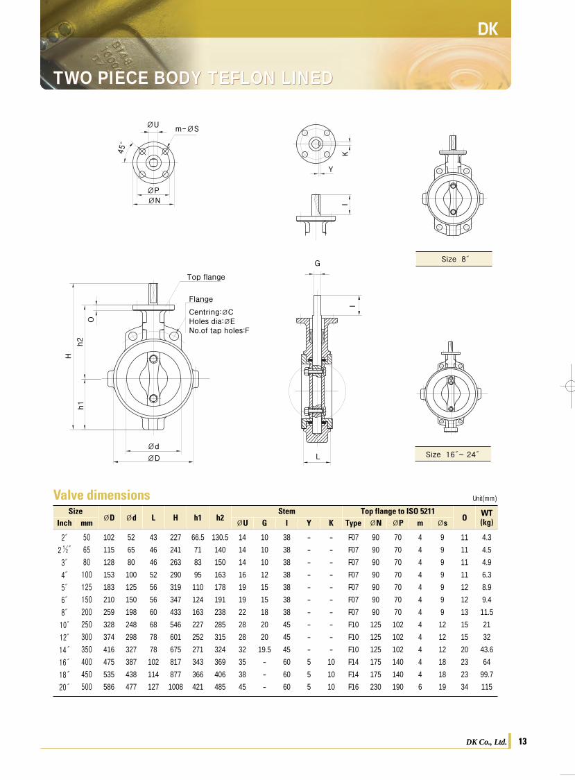
TWO PIECE BODY TEFLON LINED
12
TWO PIECE SPLIT BODY TEFLONⓇ LINED TWO PIECE BODY TEFLON LINEDTWO PIECE SPLIT BODY TEFLONⓇ LINED
SizeØD Ød L H h1 h2
Stem Top flange to ISO 5211O WT
(kg)Inch
2″
2½″
3″
4″
5″
6″
8″
10″
12″
14″
16″
18″
20″
50
65
80
100
125
150
200
250
300
350
400
450
500
102
115
128
153
183
210
259
328
374
416
475
535
586
52
65
80
100
125
150
198
248
298
327
387
438
477
43
46
46
52
56
56
60
68
78
78
102
114
127
227
241
263
290
319
347
433
546
601
675
817
877
1008
66.5
71
83
95
110
124
163
227
252
271
343
366
421
130.5
140
150
163
178
191
238
285
315
324
369
406
485
14
14
14
16
19
19
22
28
28
32
35
38
45
10
10
10
12
15
15
18
20
20
19.5
-
-
-
38
38
38
38
38
38
38
45
45
45
60
60
60
-
-
-
-
-
-
-
-
-
-
5
5
5
-
-
-
-
-
-
-
-
-
-
10
10
10
F07
F07
F07
F07
F07
F07
F07
F10
F10
F10
F14
F14
F16
90
90
90
90
90
90
90
125
125
125
175
175
230
70
70
70
70
70
70
70
102
102
102
140
140
190
4
4
4
4
4
4
4
4
4
4
4
4
6
9
9
9
9
9
9
9
12
12
12
18
18
19
11
11
11
11
12
12
13
15
15
20
23
23
34
4.3
4.5
4.9
6.3
8.9
9.4
11.5
21
32
43.6
64
99.7
115
Unit(mm)
ØU G I Y K Type ØN ØP m Øsmm
Valve dimensionsCoated surface
Extended covering
Stainless steel disc
Stainless steel shaft
ØU
ØPØN
Ød
ØD L
G
O
I
Top flange
Flange
Centring:ØCHoles dia:ØENo.of tap holes:F
h2
H
h1
m-ØS
45°
Size 8″
Size 16″~ 24″
Y
KI
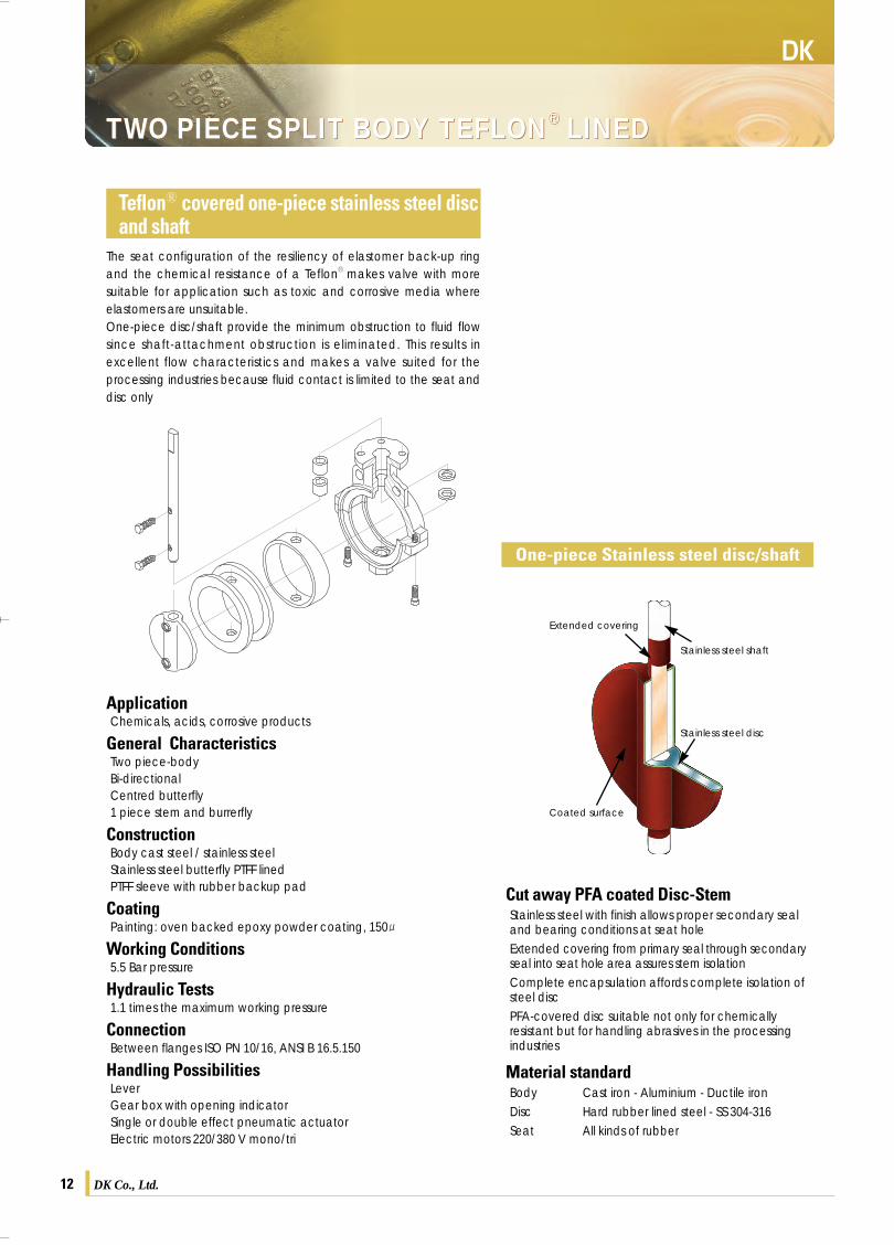
The seat configuration of the resiliency of elastomer back-up ringand the chemical resistance of a TeflonⓇ makes valve with moresuitable for application such as toxic and corrosive media whereelastomers are unsuitable.One-piece disc/shaft provide the minimum obstruction to fluid flowsince shaft-attachment obstruction is eliminated. This results inexcellent flow characteristics and makes a valve suited for theprocessing industries because fluid contact is limited to the seat anddisc only
Cut away PFA coated Disc-StemStainless steel with finish allows proper secondary seal and bearing conditions at seat holeExtended covering from primary seal through secondary seal into seat hole area assures stem isolationComplete encapsulation affords complete isolation of steel discPFA-covered disc suitable not only for chemically resistant but for handling abrasives in the processing industries
Material standardBodyDiscSeat
Cast iron - Aluminium - Ductile ironHard rubber lined steel - SS 304-316All kinds of rubber
ApplicationChemicals, acids, corrosive products
General CharacteristicsTwo piece-bodyBi-directionalCentred butterfly1 piece stem and burrerfly
ConstructionBody cast steel / stainless steelStainless steel butterfly PTFF linedPTFF sleeve with rubber backup pad
CoatingPainting: oven backed epoxy powder coating, 150
Working Conditions5.5 Bar pressure
Hydraulic Tests1.1 times the maximum working pressure
ConnectionBetween flanges ISO PN 10/16, ANSI B 16.5.150
Handling PossibilitiesLeverGear box with opening indicatorSingle or double effect pneumatic actuatorElectric motors 220/380 V mono/tri
TeflonⓇ covered one-piece stainless steel discand shaft
One-piece Stainless steel disc/shaft
DK Co., Ltd.DK Co., Ltd.
DK카다로그최종 2009.4.4 3:22 PM 페이지13
DK DK
13
TWO PIECE BODY TEFLON LINED
12
TWO PIECE SPLIT BODY TEFLONⓇ LINED TWO PIECE BODY TEFLON LINEDTWO PIECE SPLIT BODY TEFLONⓇ LINED
SizeØD Ød L H h1 h2
Stem Top flange to ISO 5211O WT
(kg)Inch
2″
2½″
3″
4″
5″
6″
8″
10″
12″
14″
16″
18″
20″
50
65
80
100
125
150
200
250
300
350
400
450
500
102
115
128
153
183
210
259
328
374
416
475
535
586
52
65
80
100
125
150
198
248
298
327
387
438
477
43
46
46
52
56
56
60
68
78
78
102
114
127
227
241
263
290
319
347
433
546
601
675
817
877
1008
66.5
71
83
95
110
124
163
227
252
271
343
366
421
130.5
140
150
163
178
191
238
285
315
324
369
406
485
14
14
14
16
19
19
22
28
28
32
35
38
45
10
10
10
12
15
15
18
20
20
19.5
-
-
-
38
38
38
38
38
38
38
45
45
45
60
60
60
-
-
-
-
-
-
-
-
-
-
5
5
5
-
-
-
-
-
-
-
-
-
-
10
10
10
F07
F07
F07
F07
F07
F07
F07
F10
F10
F10
F14
F14
F16
90
90
90
90
90
90
90
125
125
125
175
175
230
70
70
70
70
70
70
70
102
102
102
140
140
190
4
4
4
4
4
4
4
4
4
4
4
4
6
9
9
9
9
9
9
9
12
12
12
18
18
19
11
11
11
11
12
12
13
15
15
20
23
23
34
4.3
4.5
4.9
6.3
8.9
9.4
11.5
21
32
43.6
64
99.7
115
Unit(mm)
ØU G I Y K Type ØN ØP m Øsmm
Valve dimensionsCoated surface
Extended covering
Stainless steel disc
Stainless steel shaft
ØU
ØPØN
Ød
ØD L
G
O
I
Top flange
Flange
Centring:ØCHoles dia:ØENo.of tap holes:F
h2
H
h1
m-ØS45°
Size 8″
Size 16″~ 24″
Y
KI
The seat configuration of the resiliency of elastomer back-up ringand the chemical resistance of a TeflonⓇ makes valve with moresuitable for application such as toxic and corrosive media whereelastomers are unsuitable.One-piece disc/shaft provide the minimum obstruction to fluid flowsince shaft-attachment obstruction is eliminated. This results inexcellent flow characteristics and makes a valve suited for theprocessing industries because fluid contact is limited to the seat anddisc only
Cut away PFA coated Disc-StemStainless steel with finish allows proper secondary seal and bearing conditions at seat holeExtended covering from primary seal through secondary seal into seat hole area assures stem isolationComplete encapsulation affords complete isolation of steel discPFA-covered disc suitable not only for chemically resistant but for handling abrasives in the processing industries
Material standardBodyDiscSeat
Cast iron - Aluminium - Ductile ironHard rubber lined steel - SS 304-316All kinds of rubber
ApplicationChemicals, acids, corrosive products
General CharacteristicsTwo piece-bodyBi-directionalCentred butterfly1 piece stem and burrerfly
ConstructionBody cast steel / stainless steelStainless steel butterfly PTFF linedPTFF sleeve with rubber backup pad
CoatingPainting: oven backed epoxy powder coating, 150
Working Conditions5.5 Bar pressure
Hydraulic Tests1.1 times the maximum working pressure
ConnectionBetween flanges ISO PN 10/16, ANSI B 16.5.150
Handling PossibilitiesLeverGear box with opening indicatorSingle or double effect pneumatic actuatorElectric motors 220/380 V mono/tri
TeflonⓇ covered one-piece stainless steel discand shaft
One-piece Stainless steel disc/shaft
DK Co., Ltd.DK Co., Ltd.
DK카다로그최종 2009.4.4 3:22 PM 페이지13
DK
DK Co., Ltd.14
DOUBLE ECCENTRIC HIGH PERFORMANCE
DK Co., Ltd. 15
DK
WAFER BODY (SEMI LUG)
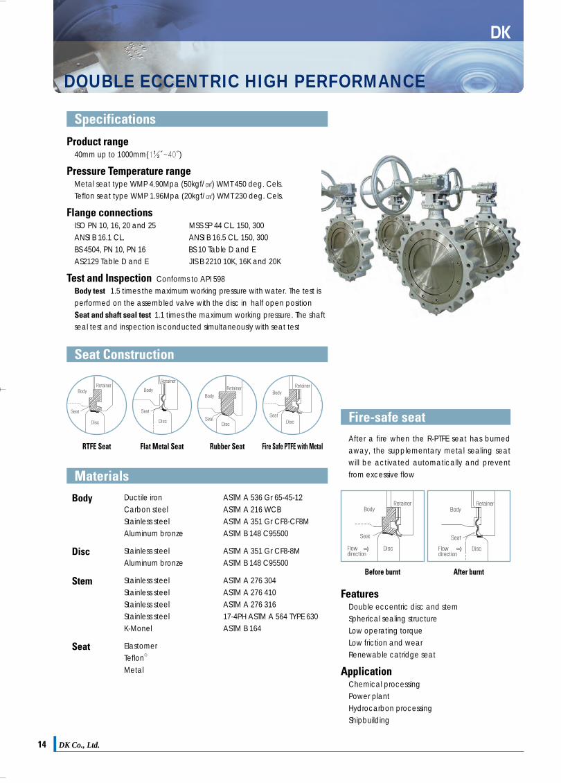
Product range40mm up to 1000mm(1½″~40″)
Pressure Temperature rangeMetal seat type WMP 4.90Mpa (50kgf/㎠) WMT 450 deg. Cels.Teflon seat type WMP 1.96Mpa (20kgf/㎠) WMT 230 deg. Cels.
Flange connectionsISO PN 10, 16, 20 and 25 MSS SP 44 CL. 150, 300ANSI B 16.1 CL. ANSI B 16.5 CL. 150, 300BS 4504, PN 10, PN 16 BS 10 Table D and EAS2129 Table D and E JIS B 2210 10K, 16K and 20K
Test and Inspection Conforms to API 598Body test 1.5 times the maximum working pressure with water. The test isperformed on the assembled valve with the disc in half open positionSeat and shaft seal test 1.1 times the maximum working pressure. The shaftseal test and inspection is conducted simultaneously with seat test
FeaturesDouble eccentric disc and stemSpherical sealing structureLow operating torqueLow friction and wearRenewable catridge seat
ApplicationChemical processing Power plantHydrocarbon processingShipbuilding
After a fire when the R-PTFE seat has burnedaway, the supplementary metal sealing seatwill be activated automatically and preventfrom excessive flow
Specifications
Seat Construction
Fire-safe seat
Body
Disc
Stem
Seat
Ductile ironCarbon steelStainless steelAluminum bronze
Stainless steelAluminum bronze
Stainless steelStainless steelStainless steelStainless steelK-Monel
ElastomerTeflonⓇ
Metal
RTFE Seat
ASTM A 536 Gr 65-45-12ASTM A 216 WCBASTM A 351 Gr CF8-CF8MASTM B 148 C95500
ASTM A 351 Gr CF8-8MASTM B 148 C95500
ASTM A 276 304ASTM A 276 410ASTM A 276 31617-4PH ASTM A 564 TYPE 630ASTM B 164
Materials
Flat Metal Seat Rubber Seat
Before burnt After burnt
Fire Safe PTFE with Metal
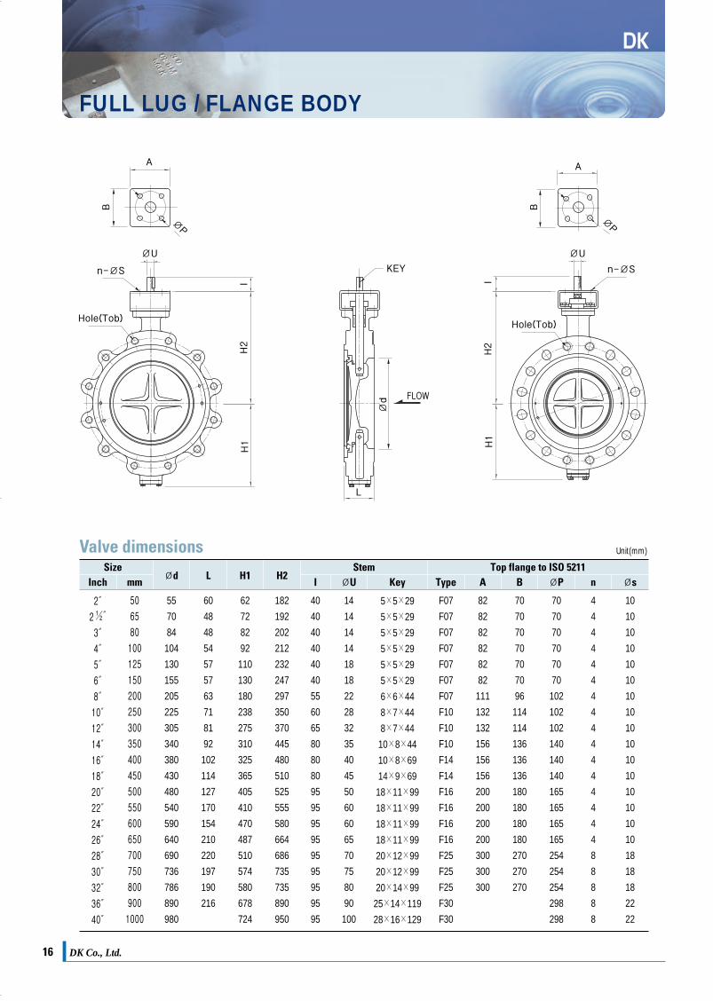
Valve dimensionsSize
Ød L H1 H2Stem Top flange to ISO 5211
Inch
2″
2½″
3″
4″
5″
6″
8″
10″
12″
14″
16″
18″
20″
22″
24″
26″
28″
30″
32″
36″
40″
50
65
80
100
125
150
200
250
300
350
400
450
500
550
600
650
700
750
800
900
1000
55
70
84
104
130
155
205
225
305
340
380
430
480
540
590
640
690
736
786
890
980
60
48
48
54
57
57
63
71
81
92
102
114
127
170
154
210
220
197
190
216
62
72
82
92
110
130
180
238
275
310
325
365
405
410
470
487
510
574
580
678
724
182
192
202
212
232
247
297
350
370
445
480
510
525
555
580
664
686
735
735
890
950
40
40
40
40
40
40
55
60
65
80
80
80
95
95
95
95
95
95
95
95
95
14
14
14
14
18
18
22
28
32
35
40
45
50
60
60
65
70
75
80
90
100
5×5×29
5×5×29
5×5×29
5×5×29
5×5×29
5×5×29
6×6×44
8×7×44
8×7×44
10×8×44
10×8×69
14×9×69
18×11×99
18×11×99
18×11×99
18×11×99
20×12×99
20×12×99
20×14×99
25×14×119
28×16×129
F07
F07
F07
F07
F07
F07
F07
F10
F10
F10
F14
F14
F16
F16
F16
F16
F25
F25
F25
F30
F30
82
82
82
82
82
82
111
132
132
156
156
156
200
200
200
200
300
300
300
70
70
70
70
70
70
96
114
114
136
136
136
180
180
180
180
270
270
270
70
70
70
70
70
70
102
102
102
140
140
140
165
165
165
165
254
254
254
298
298
4
4
4
4
4
4
4
4
4
4
4
4
4
4
4
4
8
8
8
8
8
10
10
10
10
10
10
10
10
10
10
10
10
10
10
10
10
18
18
18
22
22
Unit(mm)
ØU KeyI ØsnØPBATypemm
ØP
ØU
Ød
n-ØSKEY
FLOW
L
Hole(Tap)
A
B
H2
H1
I
Size 2″~ 6″
Size 8″~ 12″
DK카다로그최종 2009.4.4 3:22 PM 페이지15

DK
DK Co., Ltd.14
DOUBLE ECCENTRIC HIGH PERFORMANCE
DK Co., Ltd. 15
DK
WAFER BODY (SEMI LUG)
Product range40mm up to 1000mm(1½″~40″)
Pressure Temperature rangeMetal seat type WMP 4.90Mpa (50kgf/㎠) WMT 450 deg. Cels.Teflon seat type WMP 1.96Mpa (20kgf/㎠) WMT 230 deg. Cels.
Flange connectionsISO PN 10, 16, 20 and 25 MSS SP 44 CL. 150, 300ANSI B 16.1 CL. ANSI B 16.5 CL. 150, 300BS 4504, PN 10, PN 16 BS 10 Table D and EAS2129 Table D and E JIS B 2210 10K, 16K and 20K
Test and Inspection Conforms to API 598Body test 1.5 times the maximum working pressure with water. The test isperformed on the assembled valve with the disc in half open positionSeat and shaft seal test 1.1 times the maximum working pressure. The shaftseal test and inspection is conducted simultaneously with seat test
FeaturesDouble eccentric disc and stemSpherical sealing structureLow operating torqueLow friction and wearRenewable catridge seat
ApplicationChemical processing Power plantHydrocarbon processingShipbuilding
After a fire when the R-PTFE seat has burnedaway, the supplementary metal sealing seatwill be activated automatically and preventfrom excessive flow
Specifications
Seat Construction
Fire-safe seat
Body
Disc
Stem
Seat
Ductile ironCarbon steelStainless steelAluminum bronze
Stainless steelAluminum bronze
Stainless steelStainless steelStainless steelStainless steelK-Monel
ElastomerTeflonⓇ
Metal
RTFE Seat
ASTM A 536 Gr 65-45-12ASTM A 216 WCBASTM A 351 Gr CF8-CF8MASTM B 148 C95500
ASTM A 351 Gr CF8-8MASTM B 148 C95500
ASTM A 276 304ASTM A 276 410ASTM A 276 31617-4PH ASTM A 564 TYPE 630ASTM B 164
Materials
Flat Metal Seat Rubber Seat
Before burnt After burnt
Fire Safe PTFE with Metal
Valve dimensionsSize
Ød L H1 H2Stem Top flange to ISO 5211
Inch
2″
2½″
3″
4″
5″
6″
8″
10″
12″
14″
16″
18″
20″
22″
24″
26″
28″
30″
32″
36″
40″
50
65
80
100
125
150
200
250
300
350
400
450
500
550
600
650
700
750
800
900
1000
55
70
84
104
130
155
205
225
305
340
380
430
480
540
590
640
690
736
786
890
980
60
48
48
54
57
57
63
71
81
92
102
114
127
170
154
210
220
197
190
216
62
72
82
92
110
130
180
238
275
310
325
365
405
410
470
487
510
574
580
678
724
182
192
202
212
232
247
297
350
370
445
480
510
525
555
580
664
686
735
735
890
950
40
40
40
40
40
40
55
60
65
80
80
80
95
95
95
95
95
95
95
95
95
14
14
14
14
18
18
22
28
32
35
40
45
50
60
60
65
70
75
80
90
100
5×5×29
5×5×29
5×5×29
5×5×29
5×5×29
5×5×29
6×6×44
8×7×44
8×7×44
10×8×44
10×8×69
14×9×69
18×11×99
18×11×99
18×11×99
18×11×99
20×12×99
20×12×99
20×14×99
25×14×119
28×16×129
F07
F07
F07
F07
F07
F07
F07
F10
F10
F10
F14
F14
F16
F16
F16
F16
F25
F25
F25
F30
F30
82
82
82
82
82
82
111
132
132
156
156
156
200
200
200
200
300
300
300
70
70
70
70
70
70
96
114
114
136
136
136
180
180
180
180
270
270
270
70
70
70
70
70
70
102
102
102
140
140
140
165
165
165
165
254
254
254
298
298
4
4
4
4
4
4
4
4
4
4
4
4
4
4
4
4
8
8
8
8
8
10
10
10
10
10
10
10
10
10
10
10
10
10
10
10
10
18
18
18
22
22
Unit(mm)
ØU KeyI ØsnØPBATypemm
ØP
ØU
Ød
n-ØSKEY
FLOW
L
Hole(Tap)
A
B
H2
H1
I
Size 2″~ 6″
Size 8″~ 12″
DK카다로그최종 2009.4.4 3:22 PM 페이지15
DK Co., Ltd.16
DK
FULL LUG / FLANGE BODY
DK Co., Ltd. 17
DK
TRIPLE OFFSET METAL SEAT
Product range80mm ~ 1200mm
Design standardANSI B16.34 BS5155, MSS SP68, API609
Flange connectionsAPI 609, BS 5155, DIN 3840
Pressure Temperature rangeASME/ANSI 16.34
Face to Face DimensionANSI B16.10 ISO 5752, API 609 BS 5155
TestingAPI 598, MSS-SP 61, ANSI 16.104
Specifications Triple offset Design Princlples
Zero leakage (bubble tightness)Shut off and throttling of gaseous and liquid mediaLow operating torqueLong sevice lifeHigh temperature compatibility
Features
Body
Disc
Stem
Seat
Carbon Steel, Ductile iron, Stainless Steel
Aluminium Bronze
Stainless steel
Stellite overlay, Laminated Metal Seat, Solid Metal Seat
Material
Characteristics and MeritsExcellent durability of seat part and low operating torque by non-rubbing characteristics with triple offset constructionBi-directional zero leakage service by resilient metal sealing and torque seatingUnrestricted selection of face to face dimensions for API, ASME(ANSI), BS, ISO, etc. and perfect interchangeability of gate, ball, plug, high performance butterfly, and other valvesLow emission by quarter turn construction and good performance at automation by virtue of low operating torque and low cost
The valve stem is offset by seat(1st offset) and the valve seat surface centerline is offset against the center line of pipe (2nd offset) and the conical axisis offset by valve center line (3rd offset: inclined cone) The 3rd offsetcompletely eliminates rubbing.
The seat surfaces of body and seal ring in triple offset valve contact withthe inclined “cone-in cone” and this design provides excellent sealing andseat part durability by slight wedging effect.
Body SeatThe valve seat shall be integrated with the bodyStellite or stainless steel shall be applied on the seating surfaces of valve bodyThe valve seat is designed for inclined cone to ensure non-rubbing, non-jamming, bi-directional shutoff, and zero leakage
Seal Ring (Laminated)The seal ring shall be resilient stainless steel lamalla, alternated by graphite, aramid fiber and cermic fiber layersThe surface contacting between seal ring and body seat is an inclined cone type and the inclined angle generates a slight wedging effectWith a seat retainer ring bolted to the disc, the seal ring is fixed to disc not so tightly that it can be replaced easily
Laminated Metal Seat316ss+ Graphite Laminated
Hard Faced Seat Solid Metal Seat
Valve dimensionsSize
Ød L H1 H2Stem Top flange to ISO 5211
Inch
2″
2½″
3″
4″
5″
6″
8″
10″
12″
14″
16″
18″
20″
22″
24″
26″
28″
30″
32″
36″
40″
50
65
80
100
125
150
200
250
300
350
400
450
500
550
600
650
700
750
800
900
1000
55
70
84
104
130
155
205
225
305
340
380
430
480
540
590
640
690
736
786
890
980
60
48
48
54
57
57
63
71
81
92
102
114
127
170
154
210
220
197
190
216
62
72
82
92
110
130
180
238
275
310
325
365
405
410
470
487
510
574
580
678
724
182
192
202
212
232
247
297
350
370
445
480
510
525
555
580
664
686
735
735
890
950
40
40
40
40
40
40
55
60
65
80
80
80
95
95
95
95
95
95
95
95
95
14
14
14
14
18
18
22
28
32
35
40
45
50
60
60
65
70
75
80
90
100
5×5×29
5×5×29
5×5×29
5×5×29
5×5×29
5×5×29
6×6×44
8×7×44
8×7×44
10×8×44
10×8×69
14×9×69
18×11×99
18×11×99
18×11×99
18×11×99
20×12×99
20×12×99
20×14×99
25×14×119
28×16×129
F07
F07
F07
F07
F07
F07
F07
F10
F10
F10
F14
F14
F16
F16
F16
F16
F25
F25
F25
F30
F30
82
82
82
82
82
82
111
132
132
156
156
156
200
200
200
200
300
300
300
70
70
70
70
70
70
96
114
114
136
136
136
180
180
180
180
270
270
270
70
70
70
70
70
70
102
102
102
140
140
140
165
165
165
165
254
254
254
298
298
4
4
4
4
4
4
4
4
4
4
4
4
4
4
4
4
8
8
8
8
8
10
10
10
10
10
10
10
10
10
10
10
10
10
10
10
10
18
18
18
22
22
Unit(mm)
ØU KeyI ØsnØPBATypemm
ØP
ØU
Ød
n-ØS KEY
FLOW
L
Hole(Tob)
A
B
H2
H1
I
ØP
ØU
n-ØS
Hole(Tob)
A
B
H2
H1
I
DK카다로그최종 2009.4.4 3:22 PM 페이지17
DK Co., Ltd. 19DK Co., Ltd.18
DK
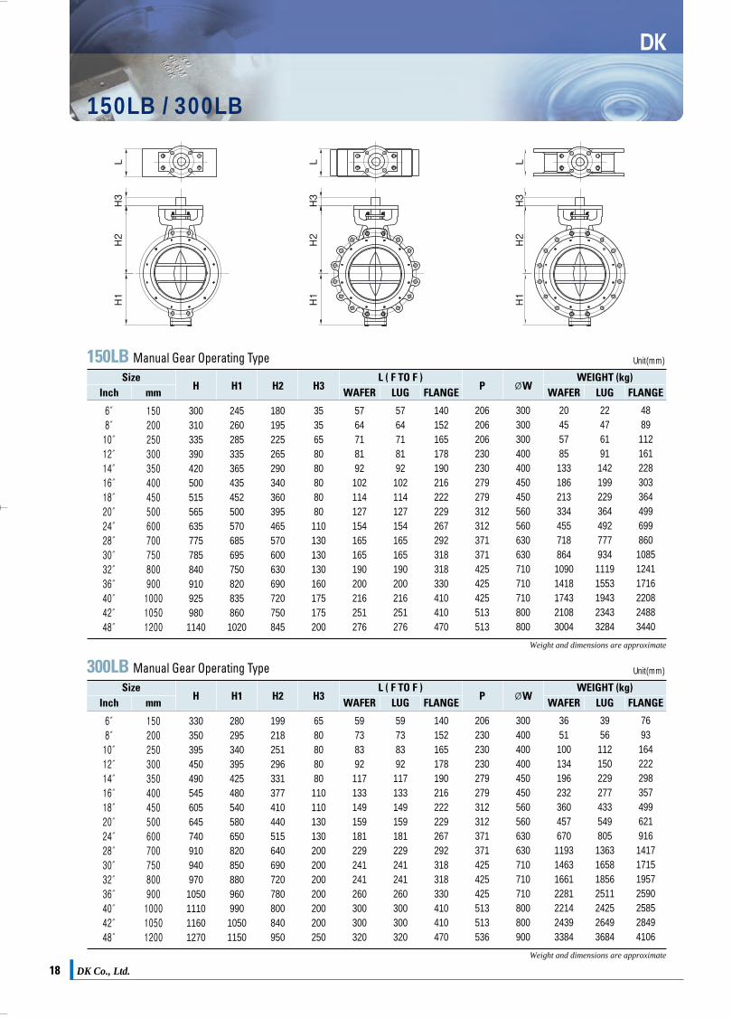
150LB / 300LB
DK
600LB / 900LB
150LB Manual Gear Operating TypeSize
H3H2H1HL ( F TO F ) WEIGHT (kg)
Inch
6″8″10″12″14″16″18″20″24″28″30″32″36″40″42″48″
150200250300350400450500600700750800900100010501200
300310335390420500515565635775785840910925980
1140
2452602853353654354525005706856957508208358601020
180195225265290340360395465570600630690720750845
3535658080808080
110130130130160175175200
5764718192102114127154165165190200216251276
5764718192102114127154165165190200216251276
140152165178190216222229267292318318330410410470
206206206230230279279312312371371425425425513513
300300300400400450450560560630630710710710800800
2045578513318621333445571886410901418174321083004
22476191142199229364492777934
11191553194323433284
4889
112161228303364499699860108512411716220824883440
Unit(mm)
P ØWFLANGELUGWAFER FLANGELUGWAFERmm
600LB Manual Gear Operating TypeSize
Inch
6″8″10″12″14″16″18″20″24″
150200250300350400450500600
365380465520535675715760840
310325400455470585625670750
23824831634937447447650455
808080110110130130130180
78102117140155178200216232
78102117140155178200216232
210230250270290310330350390
230230279312312371371425425
400400450560560630630710710
6592134224285455555694
1093
721021872593295206358041243
135162268369364632739879
1423
Unit(mm)
mm
900LB Manual Gear Operating TypeSize
Inch
6″8″10″12″14″16″18″20″24″
150200250300350400450500600
400445500590635730780830950
335380435500545640690710820
238281358383419455503550656
8080110110130130180180200
104112135170173210228250275
104112135170173210228250275
250310350380400430460490530
279312312371371425425513513
450560560630630710710800800
89134224298376570691905
1317
10015125635244066382410691704
184256425496656834
104412732506
Unit(mm)
mm
300LB Manual Gear Operating TypeSize
Inch
6″8″10″12″14″16″18″20″24″28″30″32″36″40″42″48″
150200250300350400450500600700750800900100010501200
330350395450490545605645740910940970
1050111011601270
28029534039542548054058065082085088096099010501150
199218251296331377410440515640690720780800840950
6580808080
110110130130200200200200200200250
59738392117133149159181229241241260300300320
59738392117133149159181229241241260300300320
140152165178190216222229267292318318330410410470
206230230230279279312312371371425425425513513536
300400400400450450560560630630710710710800800900
36511001341962323604576701193146316612281221424393384
3956112150229277433549805
1363165818562511242526493684
7693
1642222983574996219161417171519572590258528494106
Unit(mm)
mm
H3H2H1HL ( F TO F ) WEIGHT (kg)
P ØWFLANGELUGWAFER FLANGELUGWAFER
H3H2H1HL ( F TO F ) WEIGHT (kg)
P ØWFLANGELUGWAFER FLANGELUGWAFER
H3H2H1HL ( F TO F ) WEIGHT (kg)
P ØWFLANGELUGWAFER FLANGELUGWAFER
Weight and dimensions are approximate
Weight and dimensions are approximate
* Not specified class and size, please contact sales department
Weight and dimensions are approximate
Weight and dimensions are approximate
P
ØW
L
P
H
H1
H2
H3
L
H1
H2
H3
L
H1
H2
H3
L
DK카다로그최종 2009.4.4 3:22 PM 페이지19
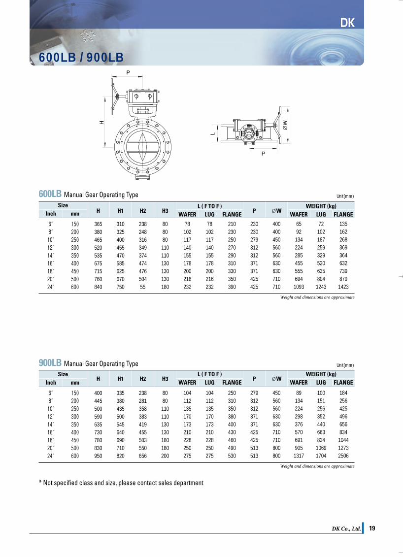
DK Co., Ltd. 19DK Co., Ltd.18
DK
150LB / 300LB
DK
600LB / 900LB
150LB Manual Gear Operating TypeSize
H3H2H1HL ( F TO F ) WEIGHT (kg)
Inch
6″8″10″12″14″16″18″20″24″28″30″32″36″40″42″48″
150200250300350400450500600700750800900100010501200
300310335390420500515565635775785840910925980
1140
2452602853353654354525005706856957508208358601020
180195225265290340360395465570600630690720750845
3535658080808080
110130130130160175175200
5764718192102114127154165165190200216251276
5764718192102114127154165165190200216251276
140152165178190216222229267292318318330410410470
206206206230230279279312312371371425425425513513
300300300400400450450560560630630710710710800800
2045578513318621333445571886410901418174321083004
22476191142199229364492777934
11191553194323433284
4889
112161228303364499699860108512411716220824883440
Unit(mm)
P ØWFLANGELUGWAFER FLANGELUGWAFERmm
600LB Manual Gear Operating TypeSize
Inch
6″8″10″12″14″16″18″20″24″
150200250300350400450500600
365380465520535675715760840
310325400455470585625670750
23824831634937447447650455
808080110110130130130180
78102117140155178200216232
78102117140155178200216232
210230250270290310330350390
230230279312312371371425425
400400450560560630630710710
6592134224285455555694
1093
721021872593295206358041243
135162268369364632739879
1423
Unit(mm)
mm
900LB Manual Gear Operating TypeSize
Inch
6″8″10″12″14″16″18″20″24″
150200250300350400450500600
400445500590635730780830950
335380435500545640690710820
238281358383419455503550656
8080110110130130180180200
104112135170173210228250275
104112135170173210228250275
250310350380400430460490530
279312312371371425425513513
450560560630630710710800800
89134224298376570691905
1317
10015125635244066382410691704
184256425496656834
104412732506
Unit(mm)
mm
300LB Manual Gear Operating TypeSize
Inch
6″8″10″12″14″16″18″20″24″28″30″32″36″40″42″48″
150200250300350400450500600700750800900100010501200
330350395450490545605645740910940970
1050111011601270
28029534039542548054058065082085088096099010501150
199218251296331377410440515640690720780800840950
6580808080
110110130130200200200200200200250
59738392117133149159181229241241260300300320
59738392117133149159181229241241260300300320
140152165178190216222229267292318318330410410470
206230230230279279312312371371425425425513513536
300400400400450450560560630630710710710800800900
36511001341962323604576701193146316612281221424393384
3956112150229277433549805
1363165818562511242526493684
7693
1642222983574996219161417171519572590258528494106
Unit(mm)
mm
H3H2H1HL ( F TO F ) WEIGHT (kg)
P ØWFLANGELUGWAFER FLANGELUGWAFER
H3H2H1HL ( F TO F ) WEIGHT (kg)
P ØWFLANGELUGWAFER FLANGELUGWAFER
H3H2H1HL ( F TO F ) WEIGHT (kg)
P ØWFLANGELUGWAFER FLANGELUGWAFER
Weight and dimensions are approximate
Weight and dimensions are approximate
* Not specified class and size, please contact sales department
Weight and dimensions are approximate
Weight and dimensions are approximate
P
ØW
L
P
H
H1
H2
H3
L
H1
H2
H3
L
H1
H2
H3
L
DK카다로그최종 2009.4.4 3:22 PM 페이지19

DK Co., Ltd. 21DK Co., Ltd.20
DK
DUAL PLATE CHECK VALVEWafer Type Class 125~500
Bolts LengthDimensions
50( 2″)
125250150300
400-600900
1500
FFFF
RF·R-22RF·R-23RF·R-23RF·R-24RF·R-24
105111105111111143143
54546060607070
60606060606060
120.6127.0120.6127.0127.0165.1165.1
4848888
5/85/85/85/85/87/87/8
145170155155175225225
--
155175180225225
3433367
500( 20″)
125250150300400600900
FFFF
RF·R-72RF·R-73RF·R-73RF·R-73RF·R-74
606654606654648683699
213292219292368368451
508508508508508508508
635685.8635
685.8685.8723.9749.3
20242024242420
1 ⅛1 ¼1 ⅛1 ¼1 ½1 ⅝
2
375520380520670670740
--
395510660660745
1803732433734216401055
600( 24″)
125250150300400600900
FFFF
RF·R-72RF·R-73RF·R-73RF·R-73RF·R-78
718775718775768791838
222318222318394438495
610610610610610610610
749.3812.8749.3812.8812.8838.12901.7
20242024242420
1 ¼1 ½1 ¼1 ½1 ¾1 ⅞2 ½
435585435582685785950
--
425575675775965
2585413945987439811700
700( 28″)
125150
FFRF
832832
321321
711711
840840
2424
1 ¼1 ¼
505505
--
634692
750( 30″)
125150300
FFRF
RF RJ95
883883953
305330398
762762762
914.4914.4966.5
282828
1 ¼1 ¼1 ¾
495580675
--
750
450580928
65( 2½″)
125250150300
400-600900
1500
FFFF
RF·R-25RF·R-26RF·R-26RF·R-27RF·R-27
124130124130130165165
60606767678383
73737373737373
139.7149.3139.7149.3149.3190.5190.5
4848888
5/83/45/83/43/411
150180165175195250250
--
165195195250250
4544478
Unit(mm)
Weight(kg)
BoltsDiameter
Number ofBolts
Flange BoltCircle
Size Series Flange FaceFF·RFØCBØA RJ
Bolts LengthDimensions
Unit(mm)
Weight(kg)
BoltsDiameter
Number ofBolts
Flange BoltCircle
Size Series Flange FaceFF·RFØCBØA RJ
VALVE SIZE 1 1/2″, 2″, 3″, ……, 24″
FLANGESTANDARD ANSI B 16.5
26″, 28″, ……, 60″
ASME B 16.47 SERIES A( MSS SP44)
72″, 90″
AWWA C207 CLASS D( 175 ~150PSI)
80( 3″)
125250150300
400-600900
1500
FFFF
RF·R-29RF·R-31RF·R-31RF·R-31RF·R-35
137149137149149168175
67677373738383
89898989898989
152.4168.4152.4168.4168.4190.5203.2
4848888
5/83/45/83/43/47/81 ⅛
160195175190210240270
--
180205210235270
57677
1314
100( 4″)
125250150300400600900
1500
FFFF
RF·R-36RF·R-37RF·R-37RF·R-37RF·R-37RF·R-39
175181175181178194206210
676773737979
102102
114114114114114114114114
190.5200.1190.5200.1200.1215.9234.9241.3
88888888
5/83/45/83/47/87/81 ⅛1 ¼
170205175195220245285310
--
180210220245280305
6888
11121821
150( 6″)
125250150300400600900
1500
FFFF
RF·R-43RF·R-43RF·R-45RF·R-45RF·R-45RF·R-46
222257222251248267289283
95959898
136136159159
168168168168168168168168
241.3269.9241.3269.9269.9292.1317.5317.5
8128
1212121212
3/43/43/43/47/81
1 ⅛1 ⅜
190240210235300315370430
--
210250300320360425
1019161931335359
200( 8″)
125250150300400600900
1500
FFFF
RF·R-48RF·R-49RF·R-49RF·R-49RF·R-49RF·R-50
279308279308305321359352
127127127127165165206206
219219219219219219219219
298.4330.2298.4330.2330.2349.2393.7393.7
8128
1212121212
3/47/83/47/81
1 ⅛1 ⅜1 ⅝
215280245280350375435505
--
250290345370440510
1936323636688997
250(10″)
125250150300400600900
1500
FFFF
RF·R-52RF·R-53RF·R-53RF·R-53RF·R-53RF·R-54
340362340362359400435435
140140146146213213241248
274274274274274274274274
361.9387.5361.9387.5387.5431.8469.9482.6
1216121616161612
7/81
7/81
1 ⅛1 ¼1 ¼1 ⅞
240315280315410435490605
--
280325415440485600
3151475196
104132140
300(12″)
125250150300400600900
1500
FFFF
RF·R-56RF·R-57RF·R-57RF·R-57RF·R-57RF·R-58
410422410422419457498521
181181181181229229292305
324324324324324324324324
431.8450.8431.8450.8450.8488.9533.4571.5
1216121616202016
7/81 ⅛7/81 ⅛1 ¼1 ¼1 ⅜
2
280370310360445465560700
--
315375440460555700
56908488
133144169178
Seat Materials Spring Materials
Buna-NNeopreneViton AViton B (FR 58/90 AntiDecompression)Teflon
410 Stainless steel (Weld)316 Stainless steel (Weld)316L Stainless steel (Weld)Stellite No 6 (Weld)Same as bodyTo be specified on P.O
316 Stainless steelInconel 625Inconel x 750MonelAs specified on Purchase Order
350(14″)
125250150300400600900
1500
FFFF
RF·R-59RF·R-61RF·R-61RF·R-61RF·R-62RF·R-63
451486451486483492521578
184222184222273273356356
356356356356356356356356
476.2514.3476.2514.3514.3527
558.8635
1220122020202016
11 ⅛
11 ⅛1 ¼1 ⅜1 ½2 ¼
315425315425495520645785
--
350415485510650800
7117697
176198198198198
400(16″)
125250150300400600900
1500
FFFF
RF·R-64RF·R-65RF·R-65RF·R-65RF·R-66RF·R-67
514540514540537565575641
191232191232305305384384
406406406406406406406406
539.7517.5539.7571.5571.5603.2615.9704.8
1620162020202016
11 ¼
11 ¼1 ⅜1 ½1 ⅝2 ½
350435350435550585690855
--
340425540575695870
99227159227268288550750
800( 32″)
125150
FFRF
920940
356356
813813
950950
2828
1 ½1 ½
550550
--
533635
900( 36″)
125150300
FFRF
RF 98
104810481117
368387489
914914914
1085.81085.81168.4
323232
1 ½1 ½
2
580605835
---
656685
1609
1000( 40″)
125150
FFRF
11621162
419419
10161016
11601160
2828
1 ½1 ½
645645
--
10651190
1050( 42″)
125150300
FFRFRF
121912191289
432432568
106710671067
1257.31257.31339.8
363636
1 ½1 ½
2
650650890
---
126013862630
1200( 48″)
125150300
FFRFRF
138413841366
524524629
121912191219
1422.41422.41543
444444
1 ½1 ½
2
750750-
---
205521802755
1350 (54″) 150 RF 1549 540 1372 1593.8 44 1 ¾ 815 - 2800
1500 (60″) 150 RF 1715 660 1524 1759 52 1 ¾ - - 3538
1800 (72″) 150 RF 2051 914 1829 2096 60 1 ¾ - - 6350
2250 (90″) 150 RF 2493 1289 2270 2550 68 1 ¼ - - -
450(18″)
125250150300400600900
1500
FFFF
RF·R-68RF·R-69RF·R-69RF·R-69RF·R-70RF·R-71
549597549579594613638705
203264203264362362451468
457457457457457457457457
577.8628.6577.8628.6628.6654
685.8774.7
1624162424202016
1 ⅛1 ¼1 ⅛1 ¼1 ⅜1 ⅝1 ⅞2 ¾
370495370495635635800985
--
390485625625800
1005
118301185301401401770980
125( 5″)
125250150300400600
FFFF
RF·R-41RF·R-41RF·R-41RF·R-41
197216197216213241
83838686
105105
141141141141141141
215.9234.9215.9234.9234.9266.7
888888
3/43/43/43/47/81
185220195215260280
--
195230260280
91410141923
B
ØC
ØA
DK카다로그최종 2009.4.4 3:22 PM 페이지21

DK Co., Ltd. 21DK Co., Ltd.20
DK
DUAL PLATE CHECK VALVEWafer Type Class 125~500
Bolts LengthDimensions
50( 2″)
125250150300
400-600900
1500
FFFF
RF·R-22RF·R-23RF·R-23RF·R-24RF·R-24
105111105111111143143
54546060607070
60606060606060
120.6127.0120.6127.0127.0165.1165.1
4848888
5/85/85/85/85/87/87/8
145170155155175225225
--
155175180225225
3433367
500( 20″)
125250150300400600900
FFFF
RF·R-72RF·R-73RF·R-73RF·R-73RF·R-74
606654606654648683699
213292219292368368451
508508508508508508508
635685.8635
685.8685.8723.9749.3
20242024242420
1 ⅛1 ¼1 ⅛1 ¼1 ½1 ⅝
2
375520380520670670740
--
395510660660745
1803732433734216401055
600( 24″)
125250150300400600900
FFFF
RF·R-72RF·R-73RF·R-73RF·R-73RF·R-78
718775718775768791838
222318222318394438495
610610610610610610610
749.3812.8749.3812.8812.8838.12901.7
20242024242420
1 ¼1 ½1 ¼1 ½1 ¾1 ⅞2 ½
435585435582685785950
--
425575675775965
2585413945987439811700
700( 28″)
125150
FFRF
832832
321321
711711
840840
2424
1 ¼1 ¼
505505
--
634692
750( 30″)
125150300
FFRF
RF RJ95
883883953
305330398
762762762
914.4914.4966.5
282828
1 ¼1 ¼1 ¾
495580675
--
750
450580928
65( 2½″)
125250150300
400-600900
1500
FFFF
RF·R-25RF·R-26RF·R-26RF·R-27RF·R-27
124130124130130165165
60606767678383
73737373737373
139.7149.3139.7149.3149.3190.5190.5
4848888
5/83/45/83/43/411
150180165175195250250
--
165195195250250
4544478
Unit(mm)
Weight(kg)
BoltsDiameter
Number ofBolts
Flange BoltCircle
Size Series Flange FaceFF·RFØCBØA RJ
Bolts LengthDimensions
Unit(mm)
Weight(kg)
BoltsDiameter
Number ofBolts
Flange BoltCircle
Size Series Flange FaceFF·RFØCBØA RJ
VALVE SIZE 1 1/2″, 2″, 3″, ……, 24″
FLANGESTANDARD ANSI B 16.5
26″, 28″, ……, 60″
ASME B 16.47 SERIES A( MSS SP44)
72″, 90″
AWWA C207 CLASS D( 175 ~150PSI)
80( 3″)
125250150300
400-600900
1500
FFFF
RF·R-29RF·R-31RF·R-31RF·R-31RF·R-35
137149137149149168175
67677373738383
89898989898989
152.4168.4152.4168.4168.4190.5203.2
4848888
5/83/45/83/43/47/81 ⅛
160195175190210240270
--
180205210235270
57677
1314
100( 4″)
125250150300400600900
1500
FFFF
RF·R-36RF·R-37RF·R-37RF·R-37RF·R-37RF·R-39
175181175181178194206210
676773737979
102102
114114114114114114114114
190.5200.1190.5200.1200.1215.9234.9241.3
88888888
5/83/45/83/47/87/81 ⅛1 ¼
170205175195220245285310
--
180210220245280305
6888
11121821
150( 6″)
125250150300400600900
1500
FFFF
RF·R-43RF·R-43RF·R-45RF·R-45RF·R-45RF·R-46
222257222251248267289283
95959898
136136159159
168168168168168168168168
241.3269.9241.3269.9269.9292.1317.5317.5
8128
1212121212
3/43/43/43/47/81
1 ⅛1 ⅜
190240210235300315370430
--
210250300320360425
1019161931335359
200( 8″)
125250150300400600900
1500
FFFF
RF·R-48RF·R-49RF·R-49RF·R-49RF·R-49RF·R-50
279308279308305321359352
127127127127165165206206
219219219219219219219219
298.4330.2298.4330.2330.2349.2393.7393.7
8128
1212121212
3/47/83/47/81
1 ⅛1 ⅜1 ⅝
215280245280350375435505
--
250290345370440510
1936323636688997
250(10″)
125250150300400600900
1500
FFFF
RF·R-52RF·R-53RF·R-53RF·R-53RF·R-53RF·R-54
340362340362359400435435
140140146146213213241248
274274274274274274274274
361.9387.5361.9387.5387.5431.8469.9482.6
1216121616161612
7/81
7/81
1 ⅛1 ¼1 ¼1 ⅞
240315280315410435490605
--
280325415440485600
3151475196
104132140
300(12″)
125250150300400600900
1500
FFFF
RF·R-56RF·R-57RF·R-57RF·R-57RF·R-57RF·R-58
410422410422419457498521
181181181181229229292305
324324324324324324324324
431.8450.8431.8450.8450.8488.9533.4571.5
1216121616202016
7/81 ⅛7/81 ⅛1 ¼1 ¼1 ⅜
2
280370310360445465560700
--
315375440460555700
56908488
133144169178
Seat Materials Spring Materials
Buna-NNeopreneViton AViton B (FR 58/90 AntiDecompression)Teflon
410 Stainless steel (Weld)316 Stainless steel (Weld)316L Stainless steel (Weld)Stellite No 6 (Weld)Same as bodyTo be specified on P.O
316 Stainless steelInconel 625Inconel x 750MonelAs specified on Purchase Order
350(14″)
125250150300400600900
1500
FFFF
RF·R-59RF·R-61RF·R-61RF·R-61RF·R-62RF·R-63
451486451486483492521578
184222184222273273356356
356356356356356356356356
476.2514.3476.2514.3514.3527
558.8635
1220122020202016
11 ⅛
11 ⅛1 ¼1 ⅜1 ½2 ¼
315425315425495520645785
--
350415485510650800
7117697
176198198198198
400(16″)
125250150300400600900
1500
FFFF
RF·R-64RF·R-65RF·R-65RF·R-65RF·R-66RF·R-67
514540514540537565575641
191232191232305305384384
406406406406406406406406
539.7517.5539.7571.5571.5603.2615.9704.8
1620162020202016
11 ¼
11 ¼1 ⅜1 ½1 ⅝2 ½
350435350435550585690855
--
340425540575695870
99227159227268288550750
800( 32″)
125150
FFRF
920940
356356
813813
950950
2828
1 ½1 ½
550550
--
533635
900( 36″)
125150300
FFRF
RF 98
104810481117
368387489
914914914
1085.81085.81168.4
323232
1 ½1 ½
2
580605835
---
6566851609
1000( 40″)
125150
FFRF
11621162
419419
10161016
11601160
2828
1 ½1 ½
645645
--
10651190
1050( 42″)
125150300
FFRFRF
121912191289
432432568
106710671067
1257.31257.31339.8
363636
1 ½1 ½
2
650650890
---
126013862630
1200( 48″)
125150300
FFRFRF
138413841366
524524629
121912191219
1422.41422.41543
444444
1 ½1 ½
2
750750-
---
205521802755
1350 (54″) 150 RF 1549 540 1372 1593.8 44 1 ¾ 815 - 2800
1500 (60″) 150 RF 1715 660 1524 1759 52 1 ¾ - - 3538
1800 (72″) 150 RF 2051 914 1829 2096 60 1 ¾ - - 6350
2250 (90″) 150 RF 2493 1289 2270 2550 68 1 ¼ - - -
450(18″)
125250150300400600900
1500
FFFF
RF·R-68RF·R-69RF·R-69RF·R-69RF·R-70RF·R-71
549597549579594613638705
203264203264362362451468
457457457457457457457457
577.8628.6577.8628.6628.6654
685.8774.7
1624162424202016
1 ⅛1 ¼1 ⅛1 ¼1 ⅜1 ⅝1 ⅞2 ¾
370495370495635635800985
--
3904856256258001005
118301185301401401770980
125( 5″)
125250150300400600
FFFF
RF·R-41RF·R-41RF·R-41RF·R-41
197216197216213241
83838686
105105
141141141141141141
215.9234.9215.9234.9234.9266.7
888888
3/43/43/43/47/81
185220195215260280
--
195230260280
91410141923
B
ØC
ØA
DK카다로그최종 2009.4.4 3:22 PM 페이지21
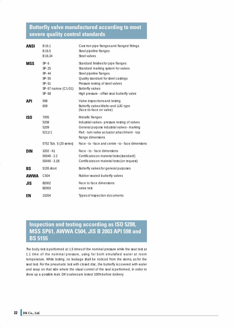
DK Co., Ltd. 23DK Co., Ltd.22
In accordance with ANSI B 16 - 104Leakage Class
Designation
Ⅰ - - -No test required provided user andsupplier so agree
Ⅱ 0.5% of rated capacityAll or water at 50~125℉(10~52℃)
45~60psig or max.operating differentialwhichever is lower
Pressure applied to valve inlet, withoutlet open to atmosphere orconcerned to a low head lossmeasuring device, full normal closingthrust provided by actuator.
Ⅲ 0.1% of rated capacity As above As above As above
Ⅳ 0.01% of rated capacity As above As above As above
Ⅴ
Ⅵ
0.05ml per minute of waterinch of port diameter perpsi differential
Not to exceed amountsshown in following tablebased on port diameter
Water at 50~125℉(10~52℃)
Air or Nitrogen at50~125℉(10~52℃)
Max. service pressuredrop across valve plugnot to exceed ANSIbody rating(100psi pressure dropminimum)
50 psig or max. rateddifferential pressureacross valve plugwhichever is lower
Pressure applied to valve inlet after fillingentire body cavity and connectedpiping with water and storking valve plugclosed.Use net specified max. actuator thrust,but no more, even if available during testAllow time for leakage flow to be stablized.
Actuator should be adjusted tooperating conditions specified with fullnormal closing thrust applied to valveplug seat.Allow time for leakage flow to bestablized and use suitable measuingdevice.
Testing Procedures Required for Establishing Ration
Test PressureTest MediumTest Medium
In accordance with ANSI B 16 - 104, FCI 70-2 (Test Procedure Type B)
Size △P(bar)
Inch mm 10 16 20
2″3″4″5″6″8″
10″
5080
100125150200250
0.150.240.3
0.380.450.6
0.75
0.240.380.480.6
0.720.961.2
0.30.480.6
0.750.91.21.5
ANSI
MSS
API
ISO
DIN
BS
AWWA
JIS
EN
B 16.1B 16.5B 16.34
SP- 6SP- 25SP- 44SP- 55SP- 61SP- 67 narrow (C1-D1)SP- 68
598609
7005520852095211/1
5752 Tab. 5 (20 series)
3202 - K150049 - 2.250049 - 3.1B
5155 short
C504
B2002B2003
10204
Cast iron pipe flanges and flanged fittingsSteel pipeline flangesSteel valves
Standard finishes for pipe flangesStandard marking system for valvesSteel pipeline flangesQuality standard for steel castingsPressure testing of steel valvesButterfly valvesHigh pressure - offset seat butterfly valve
Valve inspections and testingButterfly valves Wafer and LUG type (face-to-face on valve)
Metallic flangesIndustrial valves - pressure testing of valvesGeneral purpose industrial valves - markingPart - turn valve actuator attachment - topflange dimensions
Face - to - face and centre - to - face dimensions
Face - to - face dimensionsCertificates on material tests (standard)Certificates on material tests (on request)
Butterfly valves for general purposes
Rubber seated butterfly valves
Face to face dimensionsvalve test
Types of inspection documents
Butterfly valve manufactured according to mostsevere quality control standards
Seat Leakage Allowance
Calculated Values of Seat Leakage (Class V)
The body test is performed at 1.5 times of the nominal pressure while the seat test at1.1 time of the nominal pressure, using for both emulsified water at roomtemperature. While testing, no leakage shall be noticed from the stems, as for theseat test. For the pneumatic test with closed disc, the butterfly is covered with waterand soap on that side where the visual control of the seal is performed, in order toshow up a possible leak. DK’s valves are tested 100% before deilvery
Inspection and testing according as ISO 5208,MSS SP61, AWWA C504, JIS B 2003 API 598 andBS 5155
Unit(cc/minute)
Size △P(bar)
Inch mm 10 16 20
12″14″16″18″20″22″24″
300350400450500550600
0.91.051.21.351.51.651.8
1.441.681.922.162.42.642.88
1.82.12.42.73.03.33.6
Unit(cc/minute)
Qa(allowable leckage) (cc/minute)= 3×10⁻⁴, nominal size(mm)×△P(bar) or 0.0075nominal size(inch)×△P(bar)
△P = max. differential pressure
DK카다로그최종 2009.4.4 3:22 PM 페이지23
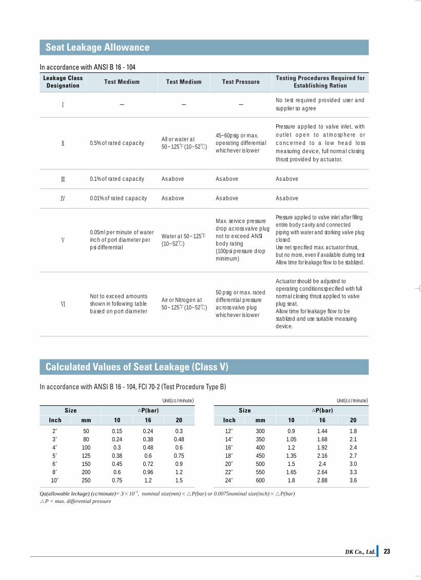
DK Co., Ltd. 23DK Co., Ltd.22
In accordance with ANSI B 16 - 104Leakage Class
Designation
Ⅰ - - -No test required provided user andsupplier so agree
Ⅱ 0.5% of rated capacityAll or water at 50~125℉(10~52℃)
45~60psig or max.operating differentialwhichever is lower
Pressure applied to valve inlet, withoutlet open to atmosphere orconcerned to a low head lossmeasuring device, full normal closingthrust provided by actuator.
Ⅲ 0.1% of rated capacity As above As above As above
Ⅳ 0.01% of rated capacity As above As above As above
Ⅴ
Ⅵ
0.05ml per minute of waterinch of port diameter perpsi differential
Not to exceed amountsshown in following tablebased on port diameter
Water at 50~125℉(10~52℃)
Air or Nitrogen at50~125℉(10~52℃)
Max. service pressuredrop across valve plugnot to exceed ANSIbody rating(100psi pressure dropminimum)
50 psig or max. rateddifferential pressureacross valve plugwhichever is lower
Pressure applied to valve inlet after fillingentire body cavity and connectedpiping with water and storking valve plugclosed.Use net specified max. actuator thrust,but no more, even if available during testAllow time for leakage flow to be stablized.
Actuator should be adjusted tooperating conditions specified with fullnormal closing thrust applied to valveplug seat.Allow time for leakage flow to bestablized and use suitable measuingdevice.
Testing Procedures Required for Establishing Ration
Test PressureTest MediumTest Medium
In accordance with ANSI B 16 - 104, FCI 70-2 (Test Procedure Type B)
Size △P(bar)
Inch mm 10 16 20
2″3″4″5″6″8″
10″
5080
100125150200250
0.150.240.3
0.380.450.6
0.75
0.240.380.480.6
0.720.961.2
0.30.480.6
0.750.91.21.5
ANSI
MSS
API
ISO
DIN
BS
AWWA
JIS
EN
B 16.1B 16.5B 16.34
SP- 6SP- 25SP- 44SP- 55SP- 61SP- 67 narrow (C1-D1)SP- 68
598609
7005520852095211/1
5752 Tab. 5 (20 series)
3202 - K150049 - 2.250049 - 3.1B
5155 short
C504
B2002B2003
10204
Cast iron pipe flanges and flanged fittingsSteel pipeline flangesSteel valves
Standard finishes for pipe flangesStandard marking system for valvesSteel pipeline flangesQuality standard for steel castingsPressure testing of steel valvesButterfly valvesHigh pressure - offset seat butterfly valve
Valve inspections and testingButterfly valves Wafer and LUG type (face-to-face on valve)
Metallic flangesIndustrial valves - pressure testing of valvesGeneral purpose industrial valves - markingPart - turn valve actuator attachment - topflange dimensions
Face - to - face and centre - to - face dimensions
Face - to - face dimensionsCertificates on material tests (standard)Certificates on material tests (on request)
Butterfly valves for general purposes
Rubber seated butterfly valves
Face to face dimensionsvalve test
Types of inspection documents
Butterfly valve manufactured according to mostsevere quality control standards
Seat Leakage Allowance
Calculated Values of Seat Leakage (Class V)
The body test is performed at 1.5 times of the nominal pressure while the seat test at1.1 time of the nominal pressure, using for both emulsified water at roomtemperature. While testing, no leakage shall be noticed from the stems, as for theseat test. For the pneumatic test with closed disc, the butterfly is covered with waterand soap on that side where the visual control of the seal is performed, in order toshow up a possible leak. DK’s valves are tested 100% before deilvery
Inspection and testing according as ISO 5208,MSS SP61, AWWA C504, JIS B 2003 API 598 andBS 5155
Unit(cc/minute)
Size △P(bar)
Inch mm 10 16 20
12″14″16″18″20″22″24″
300350400450500550600
0.91.051.21.351.51.651.8
1.441.681.922.162.4
2.642.88
1.82.12.42.73.03.33.6
Unit(cc/minute)
Qa(allowable leckage) (cc/minute)= 3×10⁻⁴, nominal size(mm)×△P(bar) or 0.0075nominal size(inch)×△P(bar)
△P = max. differential pressure
DK카다로그최종 2009.4.4 3:22 PM 페이지23
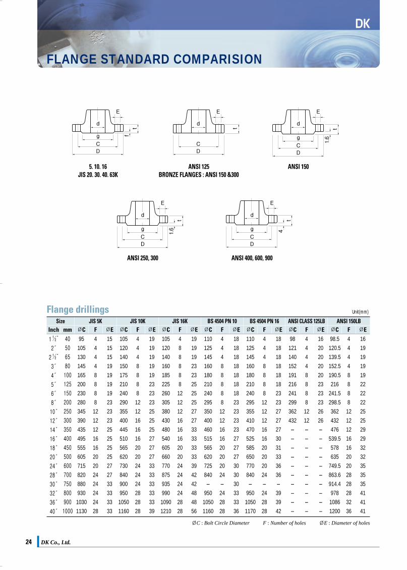
Torques For High Performance(Double Eceentric)
Triple Offset Torque
Torque Conversion Ratio Torque To Be Considered
DK Co., Ltd.24
DK
FLANGE STANDARD COMPARISION
Flange drillingsSize JIS 5K
Inch
1½″
2″
2½″
3″
4″
5″
6″
8″
10″
12″
14″
16″
18″
20″
24″
28″
30″
32″
36″
40″
40
50
65
80
100
125
150
200
250
300
350
400
450
500
600
700
750
800
900
1000
95
105
130
145
165
200
230
280
345
390
435
495
555
605
715
820
880
930
1030
1130
4
4
4
4
8
8
8
8
12
12
12
16
16
20
20
24
24
24
24
28
15
15
15
19
19
19
19
23
23
23
25
25
25
25
27
27
33
33
33
33
105
120
140
150
175
210
240
290
355
400
445
510
565
620
730
840
900
950
1050
1160
4
4
4
8
8
8
8
12
12
16
16
16
20
20
24
24
24
28
28
28
19
19
19
19
19
23
23
23
25
25
25
27
27
27
33
33
33
33
33
39
105
120
140
160
185
225
260
305
380
430
480
540
605
660
770
875
935
990
1090
1210
4
8
8
8
8
8
12
12
12
16
16
16
20
20
24
24
24
24
28
28
19
19
19
23
23
25
25
25
27
27
33
33
33
33
39
42
42
48
48
56
110
125
145
160
180
210
240
295
350
400
460
515
565
620
725
840
-
950
1050
1160
4
4
4
8
8
8
8
8
12
12
16
16
20
20
20
24
-
24
28
28
18
18
18
18
18
18
18
23
23
23
23
27
27
27
30
30
30
33
33
36
110
125
145
160
180
210
240
295
355
410
470
525
585
650
770
840
-
950
1050
1170
4
4
4
8
8
8
8
12
12
12
16
16
20
20
20
24
-
24
28
28
18
18
18
18
18
18
23
23
27
27
27
30
31
33
36
36
-
39
39
42
98
121
140
152
191
216
241
299
362
432
-
-
-
-
-
-
-
-
-
-
4
4
4
4
8
8
8
8
12
12
-
-
-
-
-
-
-
-
-
-
16
20
20
20
20
23
23
23
26
26
-
-
-
-
-
-
-
-
-
-
98.5
120.5
139.5
152.5
190.5
216
241.5
298.5
362
432
476
539.5
578
635
749.5
863.6
914.4
978
1086
1200
4
4
4
4
8
8
8
8
12
12
12
16
16
20
20
28
28
28
32
36
16
19
19
19
19
22
22
22
25
25
29
29
32
32
35
35
35
41
41
41
Unit(mm)
mm ØC F ØEJIS 10K
ØC F ØEJIS 16K
ØC F ØEBS 4504 PN 10
ØC F ØEBS 4504 PN 16
ØC F ØEANSI CLASS 125LB ANSI 150LBØC ØCF FØE ØE
DK Co., Ltd. 25
Torques for resilient seated butterfly valveThe factors affect the torque required to operate the valves·Valve diameter ·Shaft diameter ·Bearing friction coefficient ·Type of seat material
Size Inchmm
1½″40
2″50
2 ½″65
3″80
4″100
5″125
6″150
8″200
10″250
12″300
14″350
16″400
18″450
20″500
24″600
28″700
30″750
32″800
36″900
40″1000
Shut offPressure
in Bar
3.5Bar6Bar10Bar16Bar
10101314
12222525
17232829
25353137
41405259
58667489
8791109126
156170180260
243276320390
342389484560
4885446801520
6677628802030
887102312612493
1146132216303076
2386278132564150
2710330040505650
3000394045906040
3540434049906640
4640536069409490
63007800994013240
Unit(N.m)
Size Inchmm
2″50
2 ½″65
Class 150 DifferentialPressure (Bar)
10 Bar16 Bar
2.33.0
2.53.4
2.73.6
4.25.8
9.011.3
11.214.0
21.324.6
34.041.2
49.260.3
86.4105.0
119.2144.0
146.3183.0
190.1235.2
302.9374.4
350.1432.2
715.1917.7
917.01214.5
10701459.0
Class 300 DifferentialPressure (Bar)
10 Bar16 Bar20 Bar25 Bar
2.33.23.63.8
3.03.84.05.2
3.84.34.96.4
5.47.37.910.8
12.114.617.722.4
14.018.019.427.6
28.026.036.753.7
43.051.658.886.8
65.278.389.0130.1
95.8121.2138.3210.3
136.8176.2228.3339.6
173.0232.3270.4408.1
238.3319.7380.0580.3
372.3491.0574.6879.3
----
----
----
----
Unit(kgf.m)
3″80
4″100
5″125
6″150
8″200
10″250
12″300
14″350
16″400
18″450
20″500
24″600
28″700
32″800
36″900
40″1000
3059118233
The torque is actuator sizing torque at pressure differential. Minimum 20% additional safety factor to be considered and hydrodynamic torque may be considered at given flow condition
Torque plays an important part in the cost, operation and lifespan of butterfly valves. The following explains why.Bearing friction, seal or seating friction, and fluid dynamic effectson the disc are primary factors in determining requirements for abutterfly valve. These are described below.Any unbalanced pressure across the butterfly valve disc placesa direct load on the shaft bearings. The projected area of thedisc decreases with valve opening, this bearing friction variesfrom maxium as the disc rotates from the closed to the fully openposition.Seating friction is maximum during the first few degrees ofopening (or the last few degrees of closing) and is the result ofthe valve disc edge action against the seat.The seating torque acts to oppose the rotation of the disc.The contact of the seat around the full periphery of the disccreates the bubble tight seal.From the dynamic standpoint, a butterfly valve disc is torquebalanced only when totally closed for ful ly open. In allintermediate positions, a fluid dynamic torque is presentbecause the fluid velocity over the disc surface is always higheron the trailing edge of the disc than on the leading edqe. Thistorque acts in a valve “disc - closing” direction, tending to reachits highest point at about 70 degrees open.
DifferentialPressure
(Bar)
10 Bar20 Bar30 Bar52 Bar
Unit(N.m)
3″80
Inchmm
53104206408
4″100
73144286566
5″125
118234463916
6″150
2044037991581
8″200
31963312522480
10″250
549108721524260
12″300
661131025935134
14″350
927183636357198
16″400
154030506039
11958
18″450
19493859764015128
20″500
29215784
1145222675
24″600
Size
110009.8070.1131.356
0.0011
0.00981.13 × 10 - 4
0.0014
0.102101.972
10.011550.138
8.85885186.8
112
0.738737.67.2330.083
1
Operating Characteristics For Sizing
5. 10. 16JIS 20. 30. 40. 63K
ANSI 125BRONZE FLANGES : ANSI 150 &300
g
d
E
t
f
CD
ANSI 150
g
d
E
t
1.6
CD
ANSI 250, 300
g
d
E
t
1.6
CD
ANSI 400, 600, 900
g
d
E
t
4
CD
d
E
t
CD
ØC : Bolt Circle Diameter F : Number of holes ØE : Diameter of holes
FactorsKgf.m Ibf.in Ibf.ftKN.mN.m
DK카다로그최종 2009.4.4 3:22 PM 페이지25

Torques For High Performance(Double Eceentric)
Triple Offset Torque
Torque Conversion Ratio Torque To Be Considered
DK Co., Ltd.24
DK
FLANGE STANDARD COMPARISION
Flange drillingsSize JIS 5K
Inch
1½″
2″
2½″
3″
4″
5″
6″
8″
10″
12″
14″
16″
18″
20″
24″
28″
30″
32″
36″
40″
40
50
65
80
100
125
150
200
250
300
350
400
450
500
600
700
750
800
900
1000
95
105
130
145
165
200
230
280
345
390
435
495
555
605
715
820
880
930
1030
1130
4
4
4
4
8
8
8
8
12
12
12
16
16
20
20
24
24
24
24
28
15
15
15
19
19
19
19
23
23
23
25
25
25
25
27
27
33
33
33
33
105
120
140
150
175
210
240
290
355
400
445
510
565
620
730
840
900
950
1050
1160
4
4
4
8
8
8
8
12
12
16
16
16
20
20
24
24
24
28
28
28
19
19
19
19
19
23
23
23
25
25
25
27
27
27
33
33
33
33
33
39
105
120
140
160
185
225
260
305
380
430
480
540
605
660
770
875
935
990
1090
1210
4
8
8
8
8
8
12
12
12
16
16
16
20
20
24
24
24
24
28
28
19
19
19
23
23
25
25
25
27
27
33
33
33
33
39
42
42
48
48
56
110
125
145
160
180
210
240
295
350
400
460
515
565
620
725
840
-
950
1050
1160
4
4
4
8
8
8
8
8
12
12
16
16
20
20
20
24
-
24
28
28
18
18
18
18
18
18
18
23
23
23
23
27
27
27
30
30
30
33
33
36
110
125
145
160
180
210
240
295
355
410
470
525
585
650
770
840
-
950
1050
1170
4
4
4
8
8
8
8
12
12
12
16
16
20
20
20
24
-
24
28
28
18
18
18
18
18
18
23
23
27
27
27
30
31
33
36
36
-
39
39
42
98
121
140
152
191
216
241
299
362
432
-
-
-
-
-
-
-
-
-
-
4
4
4
4
8
8
8
8
12
12
-
-
-
-
-
-
-
-
-
-
16
20
20
20
20
23
23
23
26
26
-
-
-
-
-
-
-
-
-
-
98.5
120.5
139.5
152.5
190.5
216
241.5
298.5
362
432
476
539.5
578
635
749.5
863.6
914.4
978
1086
1200
4
4
4
4
8
8
8
8
12
12
12
16
16
20
20
28
28
28
32
36
16
19
19
19
19
22
22
22
25
25
29
29
32
32
35
35
35
41
41
41
Unit(mm)
mm ØC F ØEJIS 10K
ØC F ØEJIS 16K
ØC F ØEBS 4504 PN 10
ØC F ØEBS 4504 PN 16
ØC F ØEANSI CLASS 125LB ANSI 150LBØC ØCF FØE ØE
DK Co., Ltd. 25
Torques for resilient seated butterfly valveThe factors affect the torque required to operate the valves·Valve diameter ·Shaft diameter ·Bearing friction coefficient ·Type of seat material
Size Inchmm
1½″40
2″50
2 ½″65
3″80
4″100
5″125
6″150
8″200
10″250
12″300
14″350
16″400
18″450
20″500
24″600
28″700
30″750
32″800
36″900
40″1000
Shut offPressure
in Bar
3.5Bar6Bar10Bar16Bar
10101314
12222525
17232829
25353137
41405259
58667489
8791109126
156170180260
243276320390
342389484560
4885446801520
6677628802030
887102312612493
1146132216303076
2386278132564150
2710330040505650
3000394045906040
3540434049906640
4640536069409490
63007800994013240
Unit(N.m)
Size Inchmm
2″50
2 ½″65
Class 150 DifferentialPressure (Bar)
10 Bar16 Bar
2.33.0
2.53.4
2.73.6
4.25.8
9.011.3
11.214.0
21.324.6
34.041.2
49.260.3
86.4105.0
119.2144.0
146.3183.0
190.1235.2
302.9374.4
350.1432.2
715.1917.7
917.01214.5
10701459.0
Class 300 DifferentialPressure (Bar)
10 Bar16 Bar20 Bar25 Bar
2.33.23.63.8
3.03.84.05.2
3.84.34.96.4
5.47.37.910.8
12.114.617.722.4
14.018.019.427.6
28.026.036.753.7
43.051.658.886.8
65.278.389.0130.1
95.8121.2138.3210.3
136.8176.2228.3339.6
173.0232.3270.4408.1
238.3319.7380.0580.3
372.3491.0574.6879.3
----
----
----
----
Unit(kgf.m)
3″80
4″100
5″125
6″150
8″200
10″250
12″300
14″350
16″400
18″450
20″500
24″600
28″700
32″800
36″900
40″1000
3059118233
The torque is actuator sizing torque at pressure differential. Minimum 20% additional safety factor to be considered and hydrodynamic torque may be considered at given flow condition
Torque plays an important part in the cost, operation and lifespan of butterfly valves. The following explains why.Bearing friction, seal or seating friction, and fluid dynamic effectson the disc are primary factors in determining requirements for abutterfly valve. These are described below.Any unbalanced pressure across the butterfly valve disc placesa direct load on the shaft bearings. The projected area of thedisc decreases with valve opening, this bearing friction variesfrom maxium as the disc rotates from the closed to the fully openposition.Seating friction is maximum during the first few degrees ofopening (or the last few degrees of closing) and is the result ofthe valve disc edge action against the seat.The seating torque acts to oppose the rotation of the disc.The contact of the seat around the full periphery of the disccreates the bubble tight seal.From the dynamic standpoint, a butterfly valve disc is torquebalanced only when totally closed for ful ly open. In allintermediate positions, a fluid dynamic torque is presentbecause the fluid velocity over the disc surface is always higheron the trailing edge of the disc than on the leading edqe. Thistorque acts in a valve “disc - closing” direction, tending to reachits highest point at about 70 degrees open.
DifferentialPressure
(Bar)
10 Bar20 Bar30 Bar52 Bar
Unit(N.m)
3″80
Inchmm
53104206408
4″100
73144286566
5″125
118234463916
6″150
2044037991581
8″200
31963312522480
10″250
549108721524260
12″300
661131025935134
14″350
927183636357198
16″400
15403050603911958
18″450
19493859764015128
20″500
29215784
1145222675
24″600
Size
110009.8070.1131.356
0.0011
0.00981.13 × 10 - 4
0.0014
0.102101.972
10.011550.138
8.85885186.8
112
0.738737.67.2330.083
1
Operating Characteristics For Sizing
5. 10. 16JIS 20. 30. 40. 63K
ANSI 125BRONZE FLANGES : ANSI 150 &300
g
d
E
t
f
CD
ANSI 150
g
d
E
t
1.6
CD
ANSI 250, 300
g
d
E
t
1.6
CD
ANSI 400, 600, 900
g
d
E
t
4
CD
d
E
t
CD
ØC : Bolt Circle Diameter F : Number of holes ØE : Diameter of holes
FactorsKgf.m Ibf.in Ibf.ftKN.mN.m
DK카다로그최종 2009.4.4 3:22 PM 페이지25
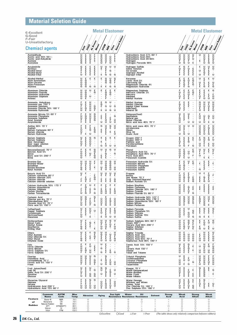
DK Co., Ltd.26 DK Co., Ltd. 27
Chemiacl agents
Unit(N.m)
DINSPEC
ASME(ASTM) KS JIS
GRADE SYMBOL SYMBOL
E-ExcellentG-GoodF-FairU-Unsatisfactory
Iron
316S
SAL
Bro
nze
Mon
el
EPDM
NBR
Vito
nN
atur
al R
ubbe
r
Iron
316S
SAL
Bro
nze
Mon
el
EPDM
NBR
Vito
nN
atur
al R
ubbe
r
Metal Elastomer Metal Elastomer
WeakAlkali
◎◎◎◎◎◎
◎
◎
◎
◎
×××
×◎
△×××△
◎
×××◎
◎◎◎◎
◎
◎
◎◎◎
◎◎
◎◎◎
◎◎◎
70℃70℃65℃80℃130℃150℃
NBRCRNR
EPDM(EPT)SI
FPM
Buna-NNeoprene
Natural RubberEPT
SiliconViton
StrongAlkali
WeakAcid
StrongAcidSolventOil
ResistanceWater
ResistanceSun light
ResistanceAgingAbrasionMaxTemp
ASTMCode
CommomName
Feature
of
Rubber
Material Seletion Guide Material Comparison
A-47
A-48
A-53
A-105
A-106
A-126
A-182
A-193
A-194
A-216
A-217
A-234
A-240
A-278
A-283
A-312
A-320
A-351
A-352
A-356
A-395
A-536
B-16
B-61
B-62
B-124
B-148
B-584
Gr. AGr. BGr. C
Cl. BCl. C
F 11F 22F 304F 304LF 316F 316L
Gr. B7
Gr. 2H
Gt. WCA
Gr. WCB
Gr. WC 1Gr. WC 6Gr. WC 9
Gr. WPA (W)Gr. WPB (W)Gr. WPC (W)
Type 304LType 304LType 316LType 316LType 321LType 410LType 430L
CI. NO. 30CI. NO. 35
Gr. D
Gr. TP 304LGr. TP 304LGr. TP 316LGr. TP 316L
Gr. B 8MGr. B 8M
Gr. CF 3MGr. CF 3MGr. CF 8MGr. CF 8MGr. CN 7M
Gr. LCBGr. LCCGr. LC1Gr. LC2Gr. LC3
Gr. 1
Gr. 2Gr. 6
Gr. 60 - 40 -18Gr. 65 - 45 -12
C36000
905 922
C83600
C37700
C95200C95400C95500C95800
C90500C83600
SPPH 38SPPH 42SPPH 49
GC 20GC 25
SFHV 23BLSFHV 24BLSFSF 304LSFSF 304LSFSF 316LSFSF 316L
SNB 7
SM 45C
SC 42SCPH 1SC 49SCPH 2SCPH 2
SCPH 11SCPH 21SCPH 22
STS 304LSTS 304LSTS 316LSTS 316LSTS 321LSTS 410LSTS 430L
GC 20GC 25
SB 41
STS 304TPLSTS 304LTPSTS 316TPLSTS 316LTP
STS 304BSTS 316B
SSC 19ASSC 16ASSC 13ASSC 14ASSC 23A
SCPL 11SCPL 11SCPL 11SCPL 21SCPL 31
SCPH 21
SCPH 11SCPH 21
DC 40DC 50
GCD 42GCD 50
C3602C3604
BrC 1, 2, 3, 4, 5BrC 1, 2, 3, 4, 4
BrC 1, 2, 3, 4, 5
FBsBE1FBsBE2
AlBrC1AlBrC2AlBrC2AlBrC3
BrC3BrC6
STS 38STS 42STS 49
FC 20FC 25
SFHV 23BLSFHV 24BLSFHV 304LSFHV 304LSFHV 316LSFHV 316L
SNB 7
S 45C
SC 42SCPH 1SC 42SCPH 2SCPH 2
SCPH 11SCPH 21SCPH 22
SUS 304LSUS 304LSUS 316LSUS 316LSUS 321LSUS 410LSUS 430L
FC 20FC 25
SS 41
SUS 304TPLSUS 304LTPSUS 316TPLSUS 316LTP
SUS 304BSUS 316B
SCS 19ASCS 16ASCS 13ASCS 14ASCS 23A
SCPL 11SCPL 11SCPL 11SCPL 21SCPL 31
SCPH 21
SCPH 11SCPH 21
FCD 40FCD 45
FCD 40FCD 50
C3602C3604
BC 1, 2, 3, 4, 5, 6, 7BC 1, 2, 3, 4, 5, 6, 7
BC 1, 2, 3, 4, 5, 6, 7
C3771B
ALBC1ALBC2ALBC2ALBC3
BC3BC6
DIN 1629 St 35.4DIN 1629 St 45.4DIN 1629 St 35.4
DIN 1691 GG - 20DIN 1691 GG - 25
SEW 610 - 13CrMo 44SEW 610 - 10CrMo 9 10DIN 17440 - 5CrNi 18 9DIN 17440 - 2CrNi 18 9DIN 17440 - 2CrNiMo 18 10DIN 17440 - 2CrNiMo 18 10
DIN 17240 - 24 CrMo5
DIN 17100 St 50-2
DIN 1681 GS - 38DIN 1681 GS - 38DIN 1681 GS - 52DIN 1681 GS - 52DIN 17245 GS - C25
DIN 17245 GS - 22Mo4DIN 17245 GS - 17CrMo55
DIN St 35.8 Ws No. 305DIN St 45.8 Ws No. 405
DIN 17440 5CrNi 18 9, 18 10DIN 17440 2CrNi 18 9DIN 17440 5CrNiMo 18 10DIN 17440 2CrNiMo 18 12DIN 17440 10CrNiTi 18 9DIN 17440 10Cr 13DIN 17440 8Cr 17
DIN 1691 GC - 20DIN 1691 GC - 25
DIN 17100 USt 42-1
DIN 2462 5CrNi 18 9
DIN 2462 5CrNi 18 12DIN 2462 2CrNiMo 18 10
SEW 680 5CrNi 18 10 A2DIN 267 A4
DIN 17445G 6CrNi 18 9DIN 17445G 7CrNiMo 18 10
SEW 685GS - CK24SEW 685GS - CK24SEW 685GS - 26CrMo4
SEW 685GS - 10Ni14
DIN 1681 GS - 52DIN 17245 GS - C25DIN 17245 GS - 22Mo4DIN 17245 GS - 17CrMo4
DIN 1693 GGG - 40DIN 1693 GGG - 50
DIN 1693 GGG - 40DIN 1693 GGG - 50
DIN 17660 CuEn36Pb1.5DIN 17660 CuEn36Pb2
DIN 1787 - CuZn40Pb2DIN 17672 - CuZn40Pb2
DIN 1714 - CuAl10FeDIN 1714 - CuAl9NiG - CuAl10NiDIN 1714 - CuAl10Ni
DIN 1705 - CuSn10ZnDIN 1705 - CuZn5ZnPb
NO. 32510NO. 35018
CI. NO. 35A~CCI. NO. 40A~C
Type S. Gr. AType S. Gr. B
BMC 35BMC 37
FCMB 35FCMB 37
DIN 1692 GTS - 10DIN 1692 GTS - 45
GC 20GC 25
FC 20FC 25
DIN 1691 GG - 20DIN 1691 GG - 25
SPPS 38 - SSPPS 42 - S
STPG 38 - SSTPG 42 - S
DIN 1629 St 35, 37DIN 1629 St 42, 45
SF 45CSM 25C
SF 45AS 25C
AcetaidihydeAcetic acid 50% 50℃Acetic acid-AnhydirdeAcetoneAcetylene
AcrylonitrileAir(Duy)Alcohol-AmylAlcohol-ButylAlcohol-Ethyl
Alcohol-MethylAlum-AmmoniumAlum-ChromeAlum-PotassiumAlumina
Aluminum ChlorideAluminum FluorideAluminum HydroxideAluminum SulphateAmines
Ammonia, AnhydrousAmmonia gas 150°FAmmonia solutionsAmmonia Chloride 50% 180°FAmmonia Hydroxide
Ammonia Nitrate 5% 60°FAmmonia PhosphateAmmonia SulphateAmyl AcetateAmylchloride
Anillne 90% 70°FAsphaltBarium Carbonate 60°FBarium chlorideBarium Hydroxide
Barium SulphateBarium SulphateBeer (beverage)Beer sugar solutionBenzaldehyde
Benzene(benzol) 70°FBenzoic Acid 5%BoraxBoric acid 5% 200°FBrine
Bromine-GasBromine-WaterButadieneButane-ButyleaeButyl Acetate
Butyric Acid 5%Calcium carbonate 60°FCalcium chlorate 20%Calcium chlorideCalcium chloride solution
Calcium Hydroxide 50% 175°FCalcium HypochloriteCalcium SulphateCarbon DioxideCarbon Tetrachloride
Carbonic AcidChlorine gas-dry 70°FChlorobenzene 90%Chromin Acid 5% 70°FCitric acid 5% 150°F
Coffee(food)Copper SulphateCyclohexaneDeztrose(food)Diacetone
DichloroethaneDiesel FuelsDiethyl AmineDowthermsDrilling Mud
EthersEthyl AcetateEthyl Dhloride 5%Ethyl GlycolEthylene Oxide
FatsFerric ChlorideFerric NitrateFerric Sulphate 5%Ferric Sulphate
FluorineFluosillicic AcidFormaldehyde 70°FFormic acid 5% 150°FFreon
Fruit Juices(food)Fuel OilGallic Acid 5% 200°FGasolineGlucose
Glycerine/GlycerolHeptaneHexaneHydrobromic Acid 200°FHydrochloric Acid 15% 60°F
U E U FU E U FU E U FG E E EG E E -
G E E EE E E EF E E EF E E EU E E E
U E E EU G - -U G - -U G - -G G G G
U U U EU G - GU G - -U G U -U E - -
F E U -U E U -F E U GU G U GU E U F
F E U GU G U GU G U GF E E GF E E -
F E F -E E E EU - G GU - - GF E U -
U E G GF E U -U E U -U E U -F E E -
F E E GU E - GU E U EU E F GU - - G
U U U FU U U FF E E -G E E EG E E -
U E - -F - - E- E - GF G F GF E F -
F E U E- G - -F E E GF E E -U G F G
U G - GU G F FF E E EU E U -U E F G
U E U -F E U UF E E -U E - -U - E -
U F - -F E G EF E E -G E E -G E - E
U E E GF E - EF E E GG E E EG E - -
E E E -U - U EU E - EU G U EF E U -
U U U GU G E -U E E GU E E GF E E E
U E U -F E E GU E - -F E G GU E G G
F E G GF E E -F E E -U U U UU U U U
G U - FG U U FU U U FG U U EU F U -
U U U UE E - -- F G -- F - -E G G G
E G U G- G G F- G G F- - - -E E G G
E E E E- G G -- G G -- E - -- F - -
E G U -G - - -E G U G- - - -E U G U
- E - -E E - GE E E -- U F UU U U U
G U G U- U E UE E - -E E E E- E - U
E E E E- E - -E - - -- E - -G U U U
U U G U- F - -- G - GE E - -E E - -
U U G UU U G U- G G -U G G UE U U U
U U U UE E E E- - - -E E E GE E E G
E E E E- F - -E E E EG G E GU U E U
- E - -U U E UU U G UU U E UE G E U
E U E EE E E GU E E U- E - -E U U U
U U G UU E E -F U U FU U E UU E - U
U U - UG U U UE E E FE E E GU U U U
U E - -- F - -G F - -- E E -G E G G
- G - -- E - -E G E -- U U UU G G U
G G - -U F E U- G G -U E E U- E E -
- E E -U E E UU G E UU U U UE U E -
Hydrochloric Acid 37% 60°FHydrochloric Acid 20%Hydrochloric Acid 20-60%HydrogenHydrogen Peroxide 90%
Hydrogen Sulfidelodine SolutionIso-octaneIsopropyl AlcoholSopropyl Ether
KeroseneLactic Acid 5%Lubricating OilMagnesium Chloride 4%Magnesium Hydroxide
Magnesium SulphateMercuric Chioride 3%MercuriyMethaneMethyl Acetate
Methyl AcetoneMethyl ChlorideMethyl Etherl KotoneMilk(food)Mineral Oil
Molasses(food)NapthaleneNatural gasNickel ChlorideNitric acid less 40% 70°F
Nitric acid more 40% 70°FnitrobenzeneOleumOlive OilOxalic Acid
Oxygen 200°FOxygen 300°FPalmitic acidPerchloroethlenePetroleum
PhenolPhosphoric Acid 5%Phosphoric Acid 85% 70°FPicric Acid 80%Potassium Cyanide
Potassium Hydroxide 5%Potassium NitratePotassium PhosphatePotassium SulfidePotassium Sulfite
PropaneResinsSea Water 70°FSoap Solution(Slearate)Sodium Acetate 5%
Sodium BisulfateSodium CarbonateSodium Chloride 30% 180°FSodium CyanideSodium Fluoride 5% 60°F
Sodium Hydroxide 50% 122°FSodium Hydroxide 50% 176°FSodium Hypochlorite 50% 60°FSodium NitrateSodium Perborate
Sodium PeroxideSodium Phosphate 5%Sodium SillicateSodium Sulfitde 70%Sodium Sulfite
Sodium Sulphate 80% 60°FSteam 300°FSteraric Acid 90% 200°FSulphur (Molten)Sulphur Dioxide
Sulphur TrioxideSulfuric Acid 10%Sulfuric Acid 50%Sulfuric Acid 93% 70°FSulphurous Acid 80% 100°F
Tannic Acid 10% 150°FTarTartaric Acid 150°FThinnerToluol and Toluene
Tributyl PhosphateTrichloroethyleneTricresyl PhosphateTriethanolamineTurpermtine
Vinegar 70°FWater-DemineralizedWater-distilledWater FreshWater Minera
Water-SewageWhiskey and WinesXylene, XylolZinc Chloride 5% 160°FZinc Sulphate 25% 180°F
U U U UU U U FU U U UF E F -U G U E
F G F -U U U EF E E EF E E EF E E E
E E E EU G U GE E E EF G F GF E G -
F E E EU F U GE E U EU E E -F E E -
F E E -G E E -E E E -U E - -F F - -
U E U -F E E -G E E -U F - -U - U U
U U U UU E - -U F - -- E - -U G U -
E E E EE E E EU E G -F E - -U G F G
U E - EU G U GU G U -U E - FF E U -
F E U EF E F GU G - -U E - -U E - -
F E E -U E E -U G G EU E E GU E E G
U E - -U E G EU E E EU E U -U - F G
U G U GU G U GU G U EU E G GU E - -
U E U -U E - GU E G GU E U -U - U G
U F G GU E G EU E F FU G U UU E F E
U E - -U G U UU U U UU U U UU U U U
U E G -F E E EU E G -U E E EU E E -
U E - -- E E -U U U -U - - GU E G -
U E - -U E E EU E U -F E E EF E E E
U E E EU E G EF E E -U F U GU E E G
U U E U- U E U- U E UE E E E- U G U
E U U U- U F UU E E -- G E -U E E U
U E E U- F - -U E E UE E E EE G E G
E E E GE E - -E E E EU E E UF U U U
G U U UU U E UU U U UE E E EU E E U
E - - -U U G UU E E U- E - -U U E U
U U F UU U G UU U E UG E E UG U G U
E G E FU U G U- E - -U F E UU E E U
U U E UF F E FF F - FU - - -- E E -
- E E -E E E E- E E -- E - -G F - -
U E E -- - G FE G E -E E E -E G U -
- E E -E E E EE E E E- E E -- - E -
E U U GG U U UG U E UE G - G- G E -
E G E GE E E EE E E E- - - -G E E -
E E E GE U U U- G - -E - E -G U E U
- U E UE U E FF U E UU U E UU U E U
- U E FU U G U- E - GU U U UU U G U
U U F FU U E UG U E UE G U UU U E U
G E E -E G E GE G - -E G - EE G - -
E G - -E E - -U U E UE E E E- E - -
◎Excellent Good △Fair ×Poor (The table shows only relatively comparison befween rubbers)
DK카다로그최종 2009.4.4 3:22 PM 페이지27
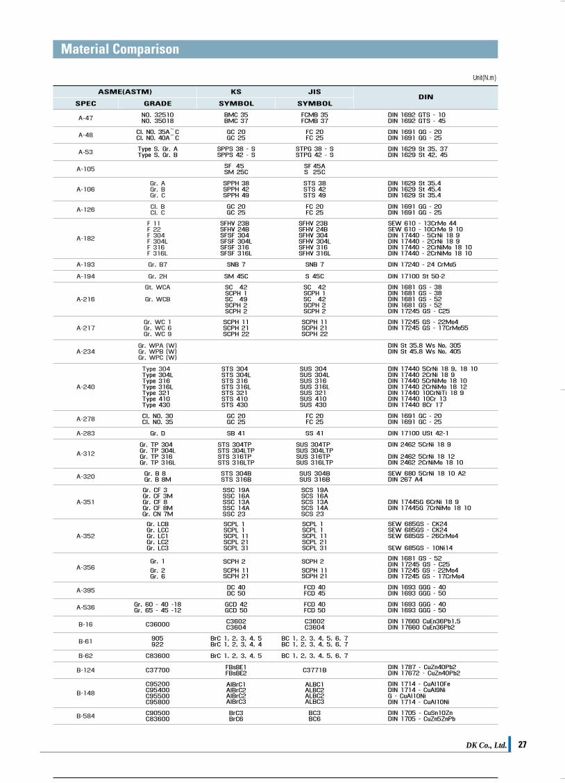
Cert No. 0062 KAB-QC-30 ISO 9001Cert No. QMS-0549
KSABUTTERFLY VALVES
CO., LTD.HEAD OFFICE #75-8, MORA-DONG, SASANG-GU, BUSAN, KOREA TEL +82-51-305-3770 FAX +82-51-305-3737
INTERNET ADDRESS http://www.dkvalve.com
E-MAIL ADDRESS [email protected] | [email protected]
DK카다로그최종 2009.4.4 3:22 PM 페이지1