kto12 bot robotics manual guide a k-12 stem education … documents/kto12bot... · 2019-04-17 ·...
TRANSCRIPT

Kto12 BOTMANUAL GUIDE A K-12 STEM EDUCATION SYSTEM
Included:- USB Cable Type A to mini B
Robotics
*(Optional) Add HC-05 module or UHF Receiver &PS2 Controller for Wireless controlled

1. Table of Contents
I. Features and General Specifications …II. Major Parts ...
(Atmega168P,PL2303 Drivers,Sensors,Motors)III. Arduino IDE Softwares and Library
IV. Board & COM Port Select ... V. Getting Started with Ardublock
a. Intro to Ardublockb. Blocks descriptionc. Add BEGIN block
VI. Ardublock Examples1. Blinking the Headlights
1.a LED Lights Diagram1.b LED Syntax & blocks
2. Controlling the Motors2.a Motor Forward2.b Reverse2.c Motor Direction syntax & Blocks2.d Changing Motor Speed & Blocks2.e Uploading Motor Test (abp format)2.f Motor Movements Illustration2.g Motor Connections Diagram

2. Table of Contents
3. Distance Sensor & Dectecting Objects3.a Add KBOT BEGIN3.b Distance sensorr Blocks3.c Reading Distance Illustration
4. Light & Dark Sensor 4.a Light & Dark Sensor Blocks 4.b Reading Light & Dark sense Illustration
5. Sound Detection Sensor 5.a Sound Sensor Blocks 5.b Reading Sound sense Illustration
6. Vibration Sensor 6.a Vibration sensor blocks 6.b Reading Vibration sensor output illustration
6.c All sensors Syntax & Blocks 6.d Uploading All sensors blocks (abp) 6.e Sensors Diagram (Sensors location)
7. Siren/ Alarm 7.a Siren Blocks 7.b Speaker Connection 7.c Siren/Alarm syntax & Blocks

3. Table of Contents
VII. eGizmo_Kto12BOT Library (Examples) 1. Uploading Headlights.ino2. Uploading Motor_Test.ino3. Uploading Sensors.ino4. Uploading Siren_Sounds.ino
VIII. Light & Dark Sensor Applications a. Uploading LightNDarkSensor.ino (with Headlights Function)
b. LightNDarkSensor Illustration c. Uploadig LightSpeedCtrl.ino (with Motor Function)d,e. LightSpeedCtrl illustration
IX. Built-in Sound Sensora. Uploading Sound_sensor.ino (with Motor Function)b. Sound command sensor illustration
X. Maze Solver or Collision Avoidancea. Uploading Maze Solver.inob. Sample Maze Trackc. Maze Sample codes
XI. Sumo Fighta. Uploading SumoFight,inob. Sumofight or Human Follower illustrationc. SumoFight Sample Codes

4. Table of Contents
XII. Bluetooth Controlled with Smartphone (Optional)a. Uploading BluetoothControlled.inob. Download the app on Play store and Intallc. Setup with HC-05 Module (wiring connections)d. Connect the HC-05 module to Smartphone
XIII. UHF Wireless with PS2 Controller (Optional)a. Uploading PS2Controlled.inob. Setup with UHF Receiverc. PS2 Controlled Functions

I. FEATURES & SPECIFICATIONS
On-Board Sensors● Distance Sensor HC-SR04 (up to 5 meters range)● LDR (Light Dependent Resistor)● Mini Microphone (Digitial and Analog sense)● Vibration Sensor (SW-18015P)● Output device: Speaker 8ohms
Li-ion Charger● TP4056 Li-ion Battery Chargeable
Motor Driver & connections● 2 Channel Motor Drivers● 2 ZebraZS-135 Motors
LED Lights● 2 Yellow LED Headlights● 1 RGB LED
On-Board IC● Atmega168P (16KB Flash Memory)● PL2303 Driver
On-Board Perpherals● On/Off Switch● 3.7V Rechargeable Battery● USB Mini B Connector● Connection for I2C and Serial
● With eGizmo_KBOT Library
● PCB Dimensions: mm x mm

HC-SR04Distance SensorUp to 4.5 Meters
Light/DarkSensor ,LDR
Sound SensorAnalog/Digital
Mini Microphone
Vibration SensorSW-18015P
Speaker 8ohmsBuzzer
2 ChannelMotor Drivers
2 DC Motors
2 HeadlightsYellow LED
RGB LED lights
ATMega168P16KB Flash Memory
Li-ion ChargerTP4056
3.7V Li-ionRechargeable Battery
I2C connectionsSerial Connections
USB ConnectorMiniTypeB Chassis
Sensors
Output Components
Serial & I2C connections
Motor Driver
Charger/Battery
On/Off ChargingSwitch
Power Switch
Microcontroller
Prolific DriverPL2303
Drivers
II. MAJOR PARTS Kto12BOT BOARD

1. Arduino IDE
2. Drivers Install this first!
Library Already added 3. Ardublock Add this on...
www.e-gizmo.net/oc/kits documents/ARDUINO IDE SOFTWARES● Download Arduino 1.8.8 (Windows)● Or choose your Arduino IDE for your OS.
Go to Arduino 1.8.8 folder>Drivers>PL2303 Driver● Install the ● (For Mac OS users) Download md_PL2303_MacOSX
● eGizmo_Kto12BOTExamples>BluetoothControlled> FireAlert> Headlights>LightNDarkSensor> LightSpeedCtrl> Maze Solver> Motor_Test>PS2Controlled> Sensors (Distance,Vibration,Sound,Light&Dark)> Siren_Sounds>Sound_Sensor> SumoFight
III. SOFTWARES AND LIBRARY INSTALLATION
● Ardublock – 031319.jarCopy the tools folder which contains “ardublock jar” file and Place it to My Documents>Arduino folder.
Be sure that you did not open the Arduino IDE yet.ReOpen the IDE after you add this.( Go to Tools> Ardublock must be included)

Connect the Kto12BOT to PC
USB Connector
USB Cable
Open Arduino IDE.

On the Arduino IDE.1. Board select Go to Tools>Boards>gizDuino (mini) w/ Atmega168
3. Port select Go to Tools>Port>COM#● Select the correct port● Go to Device Manager
if you're not sure.
IV. Arduino IDE 1.8.8
4. Click Upload Wait until its Done Uploading
The software
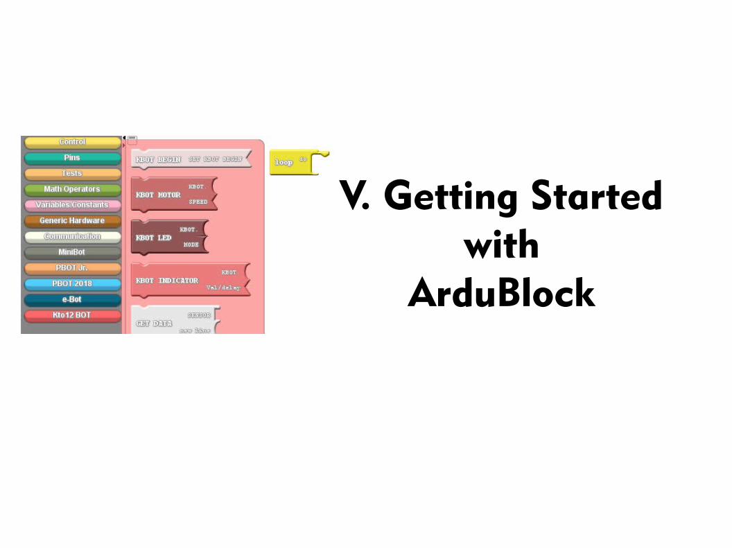
V. Getting Startedwith
ArduBlock

On the Arduino IDE.
1. Open the Ardublock. Go to Tools>Click the ArduBlock.
a. Intro to Ardublock

On the Ardublock.
Click the Kto12 BOT block.
Block descriptions
KBOT BEGIN - setting all the pins.
KBOT MOTOR – to controls themotors
KBOT LED - to use the LEDs
KBOT INDICATOR - to controls theRGB and Headlights delay.
GET DATA – read the sensors
SERIAL PRINT – print the data To the Serial Monitor.
Default 9600 baudrate.
KBOT SENSOR – to use the sensor
KBOT SIREN – for sounds
GLUE – attached the sensors
b.

Always add the KBOT BEGIN to set it.
1. Click and Drag it and attached to Loop block.
Add BEGIN block
2. If you click Upload to Arduino. (Blocks to Text Generated)
c.

VI. ArdublockExamples

Add the KBOT LED to set it.
1.Click and Drag it and attached to Loop block.
BLINKING THE HEADLIGHTS
2.You can clone the block by pressing Right-Click of your mouse then select clone.
3.Add to the 3rd blocks.
4.Then Click Upload to Arduino.
It will add this line on the loop.
See what happens?
1.
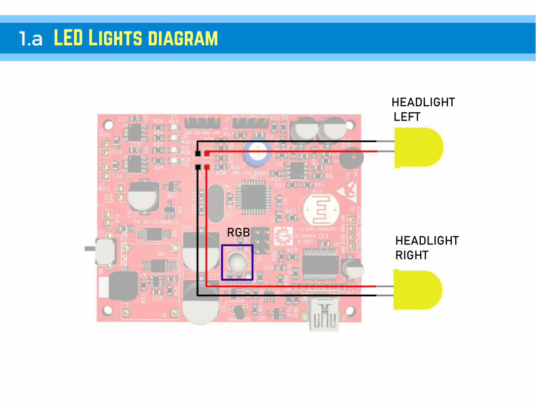
1.a LED Lights diagram
RGB
HEADLIGHT LEFT
HEADLIGHTRIGHT

// SYNTAX● KBOT.RGB(1); ● KBOT.HEADLIGHT_RIGHT(1);● KBOT.HEADLIGHT_KEFT(1);
● KBOT.REDRGB(240);● KBOT.WHITERGB(250);● KBOT.SIGNAL_LIGHT(1000);
1.b LED SYNTAX & BLOCKS
Where:● 1 = ON-state● 0 = OFF-state
Where:
● 240 = rgb set to color red● 250 = rgb set to color white● 1000 = delay time for blinking two headlights
2. Controlling the Motors

First add the “KBOT BEGIN” to set it.
1.Click KBOT MOTOR and Drag it Then attached to Loop block.
move Forward
KBOT.FORWARD(220);
2.Then Click Upload to Arduino.
It will add this line on the loop.
See what happens?
DIRECTION
SPEED
2.a

Select the direction of the motors.
1.Click the drop down arrow (shown below).
REVERSE
KBOT.REVERSE(220);
3.Upload to Arduino.
It will add this line on the loop.
See what happens?
2. Select the REVERSE.
2.b

● KBOT.FORWARD(SPEED);● KBOT.REVERSE(SPEED);● KBOT.STOP(0);● KBOT.A_FWD(SPEED);● KBOT.A_REV(SPEED);● KBOT.B_FWD(SPEED);● KBOT.B_REV(SPEED);● KBOT.TURNLEFT(SPEED);● KBOT.TURNRIGHT(SPEED);● KBOT.EXTREMERIGHT(SPEED);● KBOT.EXTREMELEFT(SPEED);
EXAMPLE: //inside the loop
KBOT.FORWARD(220); // Move Forward
2.c MOTOR DIRECTIONS SYNTAX & Blocks
Select the directions.1.Click the drop down arrow (shown below).

● KBOT.FORWARD(SPEED);● KBOT.REVERSE(SPEED);● KBOT.STOP(0);● KBOT.A_FWD(SPEED);● KBOT.A_REV(SPEED);● KBOT.B_FWD(SPEED);● KBOT.B_REV(SPEED);● KBOT.TURNLEFT(SPEED);● KBOT.TURNRIGHT(SPEED);● KBOT.EXTREMERIGHT(SPEED);● KBOT.EXTREMELEFT(SPEED);
where: SPEED = 0 , Full Stop; 255 = Maximum Speed
180 = Normal Speed
EXAMPLE: //inside the loop
KBOT.REVERSE(100); // Move Backward
2.D Changing Motor Speed & blocks
Set the Speed.
1.Click the number block. Change theValue from 0 to 255.
SPEED

Save your work.
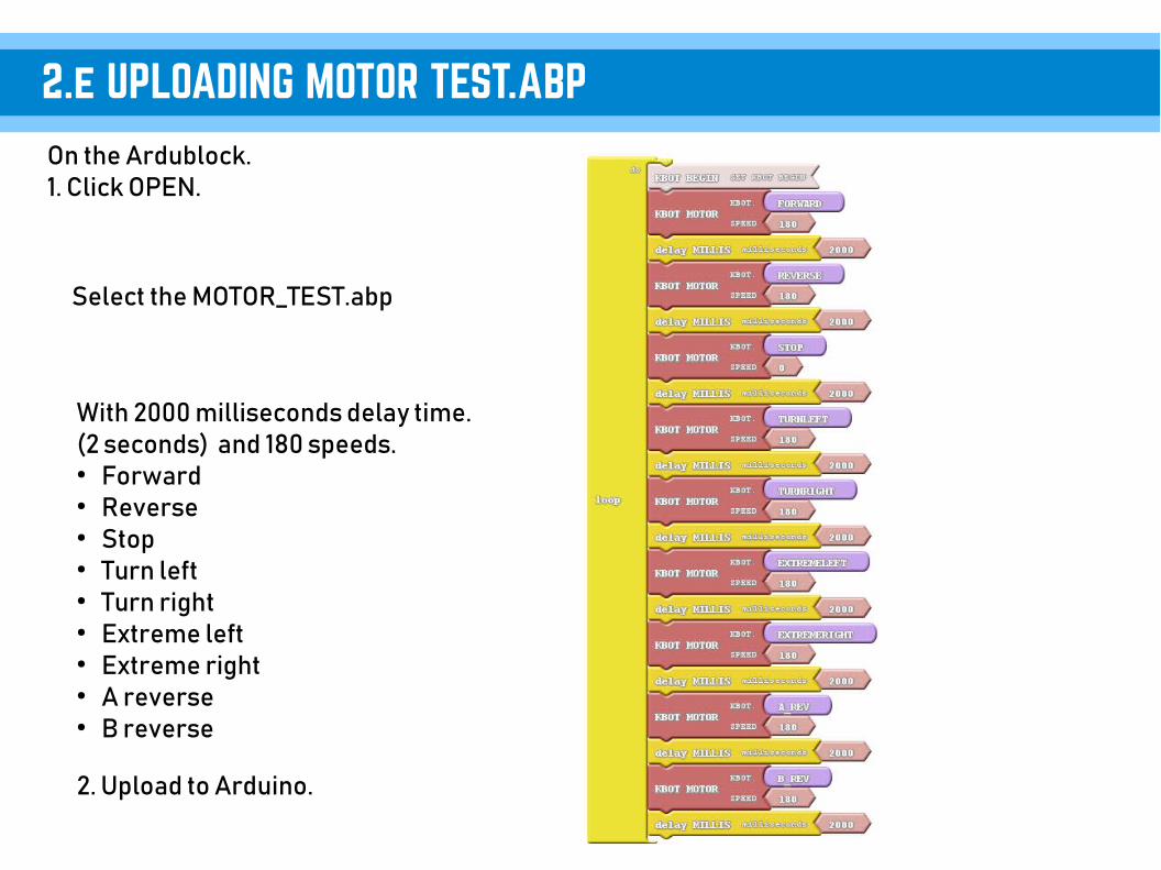
On the Ardublock.1. Click OPEN.
2.e UPLOADING MOTOR TEST.ABP
Select the MOTOR_TEST.abp
With 2000 milliseconds delay time.(2 seconds) and 180 speeds.● Forward● Reverse● Stop● Turn left● Turn right● Extreme left● Extreme right● A reverse● B reverse
2. Upload to Arduino.

2.F MOTOR MOVEMENTS ILLUSTRATION
Forward
Reverse
Stop
Turn Left
Turn Right
Extreme Left
Extreme Right
Reverse A
Forward A Forward B
Reverse B
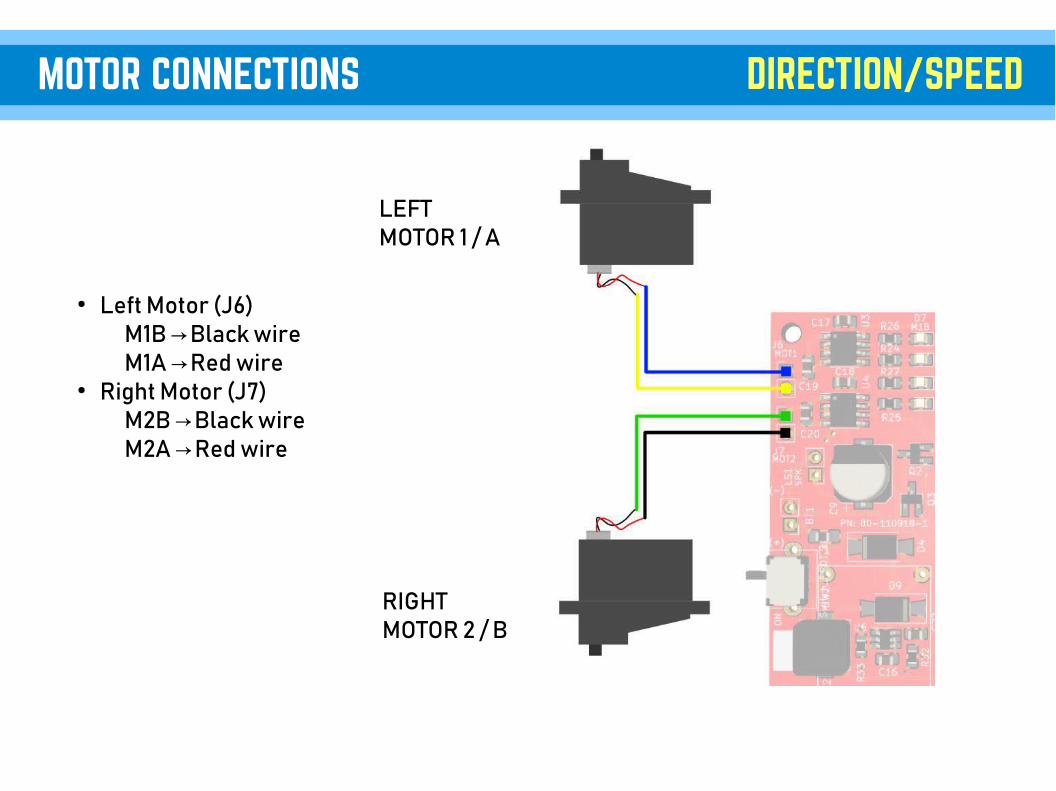
● Left Motor (J6)M1B Black wire→M1A Red wire→
● Right Motor (J7)M2B Black wire→M2A Red wire→
MOTOR CONNECTIONS DIRECTION/SPEED
LEFTMOTOR 1 / A
RIGHTMOTOR 2 / B
3. Distance Sensor&
Detecting Objects

Always add the KBOT BEGIN to set it.
1. Click and Drag it and attached to Loop block.
ADD BEGIN
2. If you click Upload to Arduino. (Blocks to Text Generated)
3.a

First add the “KBOT BEGIN” to set it.
1.Click KBOT SENSOR and Drag it Then attached to Loop block.
Distance Sensor blocks
KBOT.PRINT(“DISTANCE=”);KBOT.GET_DATA(KBOT.RANGE_IN_CM);KBOT.PRINTLN(“”);
2.Then Click Upload to Arduino.
It will add this lines to the loop.
See what happens?
Display Text
DISTANCE IN CM UNIT
3.B

3.C Reading Distance output Illustration
7 Centimeters
Serial Monitor
!Objects/Wall

4. Light & Dark sensor
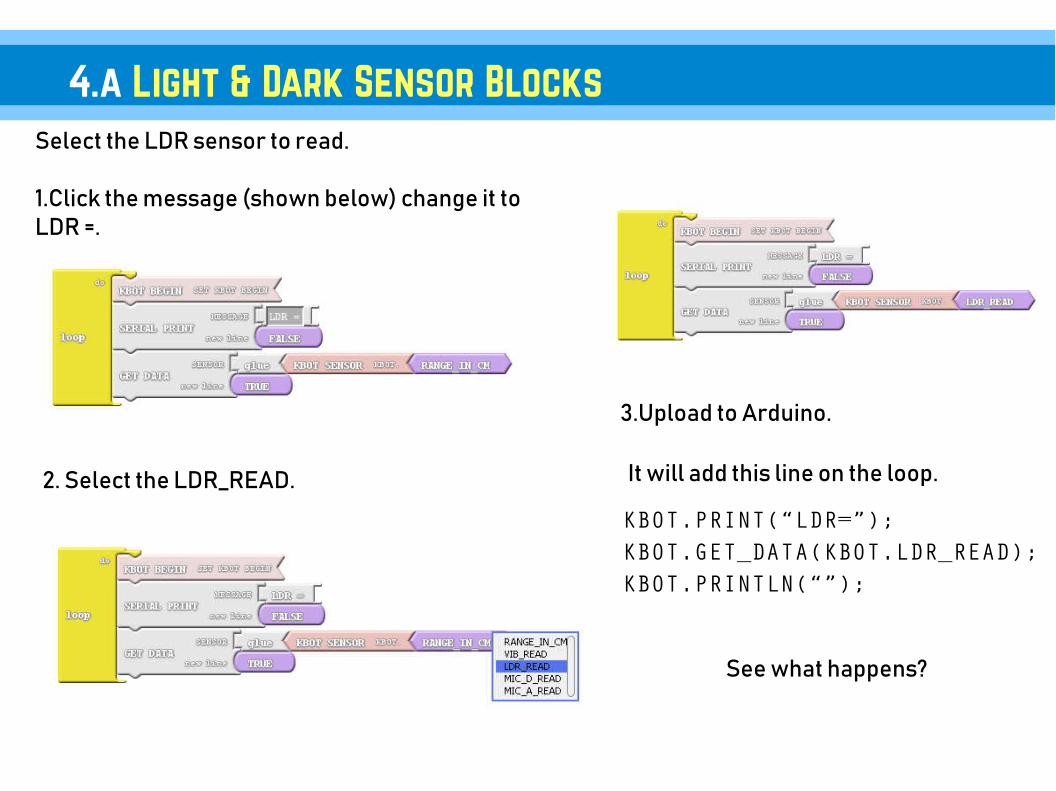
Select the LDR sensor to read.
1.Click the message (shown below) change it toLDR =.
4.a Light & Dark Sensor Blocks
KBOT.PRINT(“LDR=”);KBOT.GET_DATA(KBOT.LDR_READ);KBOT.PRINTLN(“”);
3.Upload to Arduino.
It will add this line on the loop.
See what happens?
2. Select the LDR_READ.

4.b Reading Light & Dark Output ILLUSTRATION
Light Dark
LDR <=184 LDR >=843
*using Cellphone Flashlight *using hand for cover
5. Sound Detection Sensor
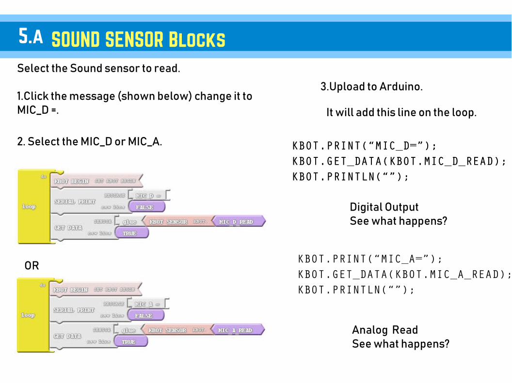
Select the Sound sensor to read.
1.Click the message (shown below) change it toMIC_D =.
SOUND SENSOR Blocks
KBOT.PRINT(“MIC_D=”);KBOT.GET_DATA(KBOT.MIC_D_READ);KBOT.PRINTLN(“”);
3.Upload to Arduino.
It will add this line on the loop.
Digital OutputSee what happens?
2. Select the MIC_D or MIC_A.
KBOT.PRINT(“MIC_A=”);KBOT.GET_DATA(KBOT.MIC_A_READ);KBOT.PRINTLN(“”);
KBOT.PRINT(“MIC_D=”);KBOT.GET_DATA(KBOT.MIC_D_READ);KBOT.PRINTLN(“”);
Analog ReadSee what happens?
OR
5.a
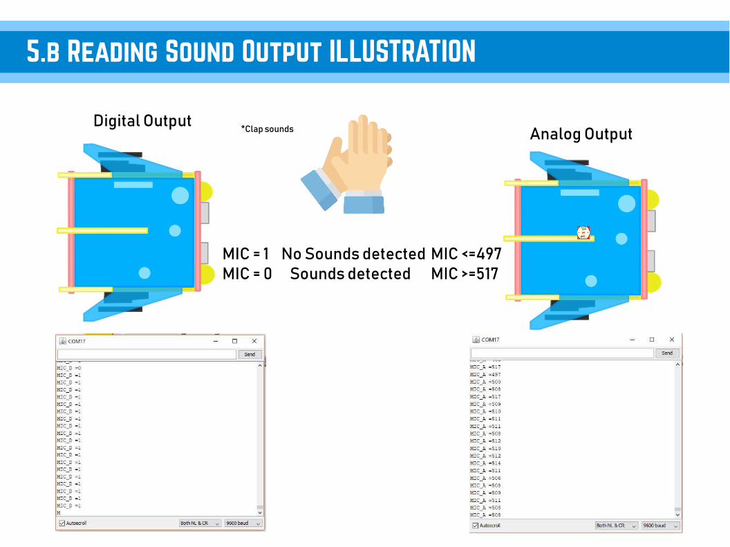
5.b Reading Sound Output ILLUSTRATION
Digital OutputAnalog Output
No Sounds detected Sounds detected
MIC <=497MIC >=517
*Clap sounds
MIC = 1MIC = 0
6. Vibration Sensor

Select the Vibration sensor to read.
1.Click the message (shown below) change it toVIBRATION =.
VIBRATION SENSOR Blocks
KBOT.PRINT(“VIBRATION=”);KBOT.GET_DATA(KBOT.VIB_READ);KBOT.PRINTLN(“”);
3.Upload to Arduino.
It will add this line on the loop.
See what happens?
2. Select the VIB_READ.
6.A

6.B Reading Vibration Output ILLUSTRATION
Digital Output
* You need strong impact / Shake
VIBRATION = 1, SHAKE DETECTEDVIBRATION = 0, NO DETECTED

READING THE LDR,DISTANCE,SOUND,VIBRATION//Setting the LDR sensor for reading
● KBOT.LDR_SENSE(); ● KBOT.MEASURE_IN_CM();● KBOT.MIC_DIGITAL();● KBOT.MIC_ANALOG();● KBOT.VIB_SENSE();●
DISPLAY ALL THE SENSOR'S OUTPUT VALUE//Getting the value and display it on the Serial Monitor
● KBOT.GET_DATA(K12BOT.LDR_READ); ● KBOT.GET_DATA(K12BOT.RANGE_IN_CM);● KBOT.GET_DATA(K12BOT.MIC_D_READ);● KBOT.GET_DATA(K12BOT.MIC_A_READ);● KBOT.GET_DATA(K12BOT.VIB_READ);
EXAMPLE: //inside the loop
KBOT.MEASURE_IN_CM();KBOT.GET_DATA(K12BOT.RANGE_IN_CM); //Display the value
KBOT.PRINTLN(“ ”);
Where:● LDR_READ● RANGE_IN_CM● MIC_D_READ● MIC_A_READ● VIB_READ
6.C All SENSORS SYNTAX & Blocks
Select the directions.1.Click the drop down arrow (shown below).

Save your work.

On the Ardublock.1. Click OPEN.
6.d UPLOADING SENSORS.ABP
Select the SENSORS.abp
Displaying data in Serial Monitor.● LDR read● Range in centimeter● Mic Digital output● Mic Analog output● Vibration read
2. Upload to Arduino.

6.e Sensor Locations SENSORS Diagram
Mini MicrophoneSound sensor
Distance sensor HC-SR04
Vibration Sensor
Light and Dark Sensor

7. Siren/Alarm

Select the Alarm.
SIREN BLOCKS
3.Upload to Arduino.
It will add this line on the loop.
See what happens?
1. Select the SIREN and set the alarm.
KBOT.ALARM():
7.A

SPEAKER
7.B SPEAKER CONNECTION SIREN/ALARM

// SYNTAX● KBOT.MARIO(); ● KBOT.HBD(); ● KBOT.ALARM(); ● KBOT.HORN(); ● KBOT.AMBULANCE();● KBOT.POLICE();● KBOT.FIRE();
7.c SIREN/ALARM SYNTAX & Blocks

VII. eGizmo_Kto12BOTLibrary
“Examples”

On the Arduino IDE.1. Headlights.ino codes Go to File>Examples>eGizmo_Kto12BOT>Headlights
2. Board select Go to Tools>Boards>gizDuino (mini) w/ Atmega168
3. Port select Go to Tools>Port>COM#● Select the correct port● Go to Device Manager
if you're not sure.
UPLOADING HEADLIGHTS
4. Click Upload Wait until its Done Uploading
See what happens?

On the Arduino IDE.1. Motor_Test.ino codes Go to File>Examples>eGizmo_Kto12BOT>Motor_Test
2. Board select Go to Tools>Boards>gizDuino (mini) w/ Atmega168
3. Port select Go to Tools>Port>COM#● Select the correct port● Go to Device Manager
if you're not sure.
UPLOADING MOTOR TEST
4. Click Upload Wait until its Done Uploading
See what happens?

On the Arduino IDE.1. Sensors.ino codes Go to File>Examples>eGizmo_Kto12BOT>Sensors
2. Board select Go to Tools>Boards>gizDuino (mini) w/ Atmega168
3. Port select Go to Tools>Port>COM#● Select the correct port● Go to Device Manager
if you're not sure.
UPLOADING SENSORS
4. Click Upload Wait until its Done Uploading
See what happens?

On the Arduino IDE.1. Siren_Sounds.ino codes Go to File>Examples>eGizmo_Kto12BOT>Siren_Sounds
2. Board select Go to Tools>Boards>gizDuino (mini) w/ Atmega168
3. Port select Go to Tools>Port>COM#● Select the correct port● Go to Device Manager
if you're not sure.
UPLOADING Siren_sounds.ino
4. Click Upload Wait until its Done Uploading
See what happens?

Light and Dark SensorApplications

On the Arduino IDE.1. LightNDarkSensor.ino codes Go to File>Examples>eGizmo_Kto12BOT> LightNDarkSensor
2. Board select Go to Tools>Boards>gizDuino (mini) w/ Atmega168
3. Port select Go to Tools>Port>COM#● Select the correct port● Go to Device Manager
if you're not sure.
A. UPLOADING LightNdarkSensor
4. Click Upload Wait until its Done Uploading
With Headlights Function
See what happens?
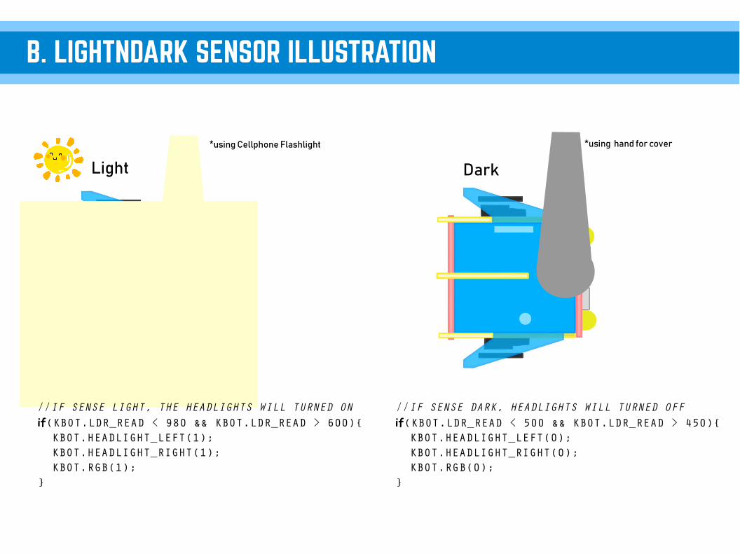
B. LIGHTNDARK SENSOR ILLUSTRATION
Light Dark
*using Cellphone Flashlight *using hand for cover
//IF SENSE LIGHT, THE HEADLIGHTS WILL TURNED ON if(KBOT.LDR_READ < 980 && KBOT.LDR_READ > 600){ KBOT.HEADLIGHT_LEFT(1); KBOT.HEADLIGHT_RIGHT(1); KBOT.RGB(1); }
//IF SENSE DARK, HEADLIGHTS WILL TURNED OFF if(KBOT.LDR_READ < 500 && KBOT.LDR_READ > 450){ KBOT.HEADLIGHT_LEFT(0); KBOT.HEADLIGHT_RIGHT(0); KBOT.RGB(0); }

On the Arduino IDE.1. LightSpeedCtrl.ino codes Go to File>Examples>eGizmo_Kto12BOT> LightSpeedCtrl
2. Board select Go to Tools>Boards>gizDuino (mini) w/ Atmega168
3. Port select Go to Tools>Port>COM#● Select the correct port● Go to Device Manager
if you're not sure.
C. UPLOADING LightSpeedCtrl
4. Click Upload Wait until its Done Uploading
With Motor Function
See what happens?

D. LightSpeed controls Motor illustration
Light
*using Cellphone Flashlight
//IF SENSES THE LIGHT WITHIN THIS RANGE THE HEADLIGHTS WILL TURNED ON AND MOVE FORWARD if(KBOT.LDR_READ < 400 && KBOT.LDR_READ > 60){ /*MOVE FORWARD*/ KBOT.FORWARD(255); KBOT.HEADLIGHT_LEFT(1); KBOT.HEADLIGHT_RIGHT(1); KBOT.RGB(1);
}
Waiting for
The range of analogIs from 0 to 1023.
To move it forward.You need a range between400 to 600
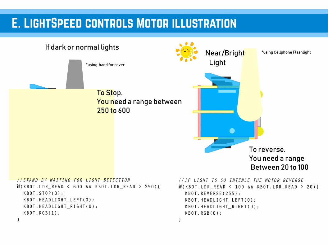
E. LightSpeed controls Motor illustration
Light
If dark or normal lights*using Cellphone Flashlight
*using hand for cover
//STAND BY WAITING FOR LIGHT DETECTION if(KBOT.LDR_READ < 600 && KBOT.LDR_READ > 250){ KBOT.STOP(0); KBOT.HEADLIGHT_LEFT(0); KBOT.HEADLIGHT_RIGHT(0); KBOT.RGB(1); }
//IF LIGHT IS SO INTENSE THE MOTOR REVERSE if(KBOT.LDR_READ < 100 && KBOT.LDR_READ > 20){ KBOT.REVERSE(255); KBOT.HEADLIGHT_LEFT(0); KBOT.HEADLIGHT_RIGHT(0); KBOT.RGB(0); }
Near/Bright
To Stop.You need a range between250 to 600
To reverse.You need a range Between 20 to 100

IX.Sound SensorExample

On the Arduino IDE.1. Sound_Sensor.ino codes Go to File>Examples>eGizmo_Kto12BOT>Sound_Sensor
2. Board select Go to Tools>Boards>gizDuino (mini) w/ Atmega168
3. Port select Go to Tools>Port>COM#● Select the correct port● Go to Device Manager
if you're not sure.
A. UPLOADING Sound Sensor
4. Click Upload Wait until its Done Uploading
With Motor Functions
See what happens?

B. SOUND SENSOR ILLUSTRATION
Digital Output Sound detected No Sounds detected
*Clap sounds
MIC = 1MIC = 0
Sound Sensor If you Clap once, the output must be Equal to 1.
// IF SOUND IS SENSED, THE HEADLIGHT WILL TURN ONS AND ROBOT WILL MOVE FORWARD if(KBOT.MIC_D_READ == 1){ KBOT.FORWARD(255); KBOT.HEADLIGHT_LEFT(1); KBOT.HEADLIGHT_RIGHT(1); delay(2000); } else {// HEADLIGHTS OFF AND MOTOR STOPS KBOT.HEADLIGHT_LEFT(0); KBOT.HEADLIGHT_RIGHT(0); KBOT.STOP(0); }

X. Maze Solveror
Collision Avoidance

On the Arduino IDE.1. MazeSolver.ino codes Go to File>Examples>eGizmo_Kto12BOT>MazeSolver
2. Board select Go to Tools>Boards>gizDuino (mini) w/ Atmega168
3. Port select Go to Tools>Port>COM#● Select the correct port● Go to Device Manager
if you're not sure.
UPLOADING MAZE SOLVER
4. Click Upload Wait until its Done Uploading
See what happens?

B. Sample Maze Track
SAMPLE MAZE TRACK
START
FINISHED

C. MAZE Sample Codes
// IF NO OBSTRUCTION, MOVE FORWARD if(KBOT.RANGE_IN_CM > DETECT_RANGE || KBOT.RANGE_IN_CM == 0){ KBOT.FORWARD(SPEED); KBOT.HEADLIGHT_LEFT(1); KBOT.HEADLIGHT_RIGHT(1); KBOT.RGB(1); } // IF THERE'S A WALL, REVERSE THEN TURN LEFT AND LOOK FOR STRAIGHT PATH if((KBOT.RANGE_IN_CM <= DETECT_RANGE && KBOT.RANGE_IN_CM !=0)){ KBOT.HEADLIGHT_LEFT(1); KBOT.HEADLIGHT_RIGHT(0); KBOT.EXTREMELEFT(SPEED); delay(1000);
}

XI.Sumo Fight

On the Arduino IDE.1. SumoFight.ino codes Go to File>Examples>eGizmo_Kto12BOT>SumoFight
2. Board select Go to Tools>Boards>gizDuino (mini) w/ Atmega168
3. Port select Go to Tools>Port>COM#● Select the correct port● Go to Device Manager
if you're not sure.
A. UPLOADING SUMO FIGHT
4. Click Upload Wait until its Done Uploading
See what happens?

B. SUMOFIGHT OR HUMAN FOLLOWER
If the Robot detects the intruderIt will move forward and bump it.
!
!
Human Follower
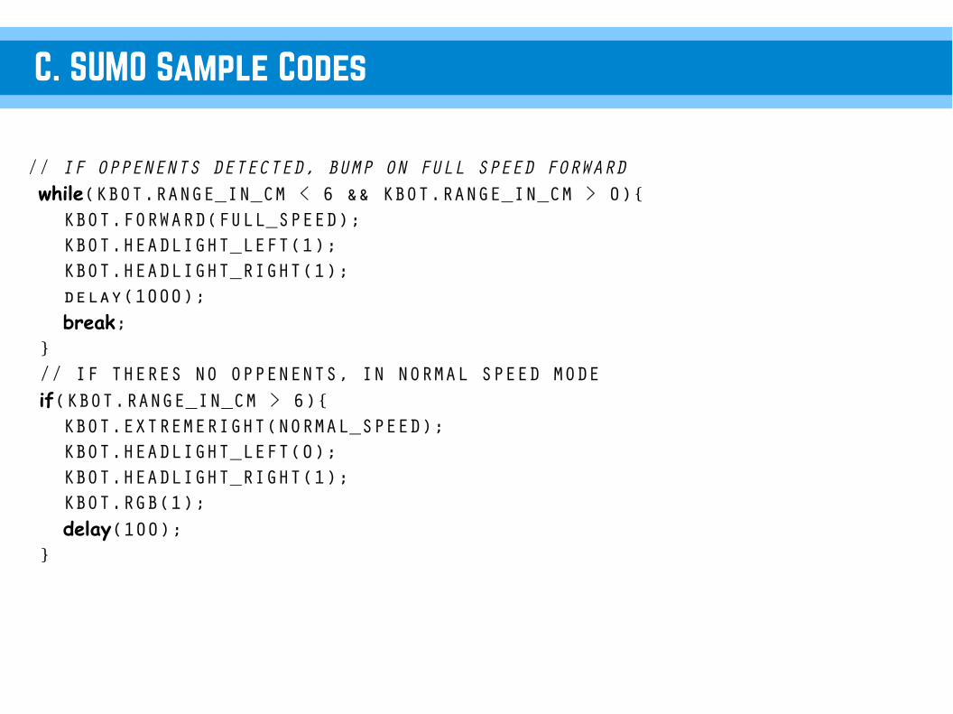
C. SUMO Sample Codes
// IF OPPENENTS DETECTED, BUMP ON FULL SPEED FORWARD while(KBOT.RANGE_IN_CM < 6 && KBOT.RANGE_IN_CM > 0){ KBOT.FORWARD(FULL_SPEED); KBOT.HEADLIGHT_LEFT(1); KBOT.HEADLIGHT_RIGHT(1); delay(1000); break; } // IF THERES NO OPPENENTS, IN NORMAL SPEED MODE if(KBOT.RANGE_IN_CM > 6){ KBOT.EXTREMERIGHT(NORMAL_SPEED); KBOT.HEADLIGHT_LEFT(0); KBOT.HEADLIGHT_RIGHT(1); KBOT.RGB(1); delay(100); }

XII.BluetoothControlled with Smart Phone

On the Arduino IDE.1. BluetoothControlled.ino codes Go to File>Examples>eGizmo_Kto12BOT> BluetoothControlled
2. Board select Go to Tools>Boards>gizDuino (mini) w/ Atmega168
3. Port select Go to Tools>Port>COM#● Select the correct port● Go to Device Manager
if you're not sure.
a.UPLOADING
4. Click Upload Wait until its Done Uploading
Bluetooth Controlled

B.DOWNLOAD THE APP ON PLAYSTORE
Connect to WIFI or DATA.
Go to Play Store;
Search for “eGizmo BT Controlled MiniBOT”And Install.

C.SETUP with HC-05 Module
Connect the HC-05 to the UART on the board.VCC +5V→RXD TX→TXD RX→GND GND→
*Note: Upload first the Code for BT controlled,Before you connect the wires, to avoid error uploading.
1pin F-F wire connector (4pcs)

D.Connect the HC-05 Module to Smartphone
On your Smartphone:1. Go to Setting> Bluetooth2. Search Device “ HC-05”3. Connect to HC-05, password: 1234 or 0000
On the App:4. Open the eGizmo BT Controlled MiniBOT5. Click the Bluetooth ICON.6. Click the HC-05 with MAC Address.7. If the Bluetooth ICON will turn in color BLUE , The connections is successful.
Now you can control the Kto12BOT.

XII. UHFWirelesswith PS2 Controller
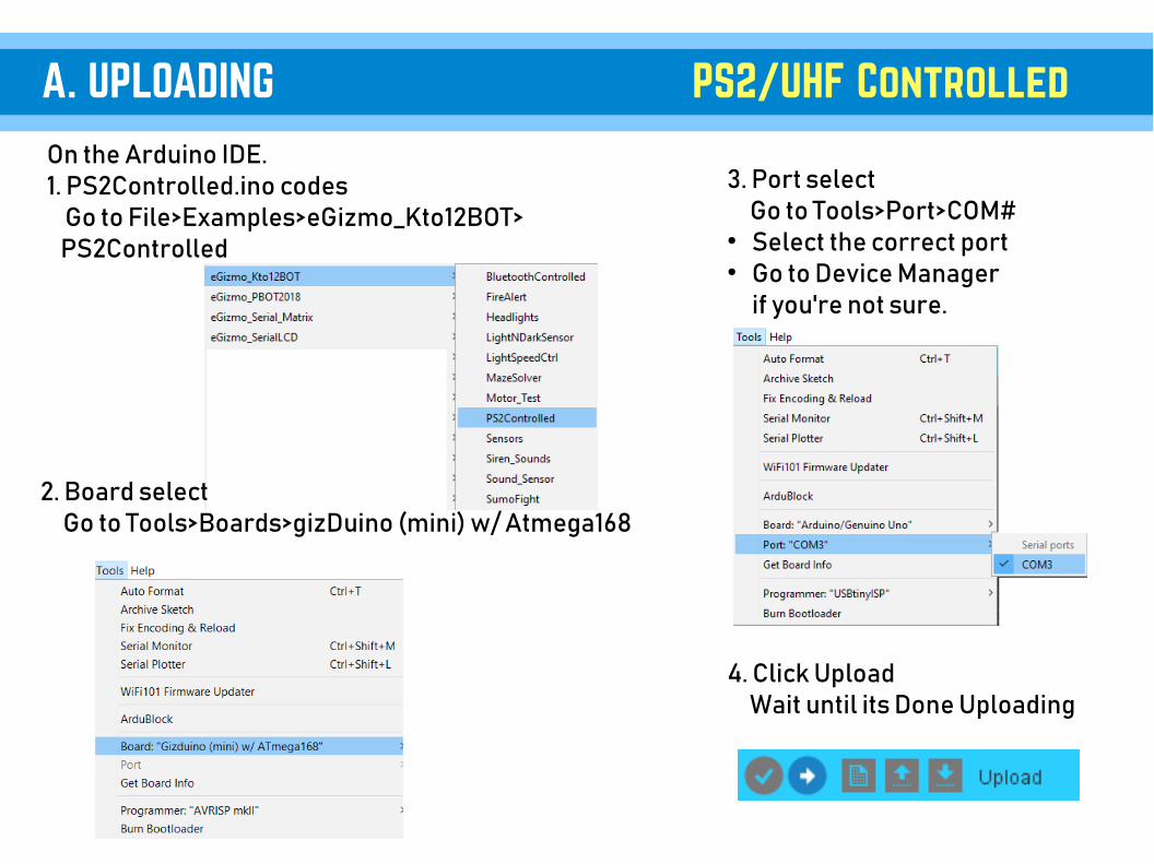
On the Arduino IDE.1. PS2Controlled.ino codes Go to File>Examples>eGizmo_Kto12BOT> PS2Controlled
2. Board select Go to Tools>Boards>gizDuino (mini) w/ Atmega168
3. Port select Go to Tools>Port>COM#● Select the correct port● Go to Device Manager
if you're not sure.
A. UPLOADING
4. Click Upload Wait until its Done Uploading
PS2/UHF Controlled

B. SETUP with UHF Receiver
Connect the UHF Receiver to the UART on the board.VCC +5V→RXD RX→TXD TX→GND GND→
*Note: Upload first the Code for PS2 controlled,Before you connect the wires, to avoid error uploading.
1pin F-F wire connector (4pcs)

C. PS2 Controller Functions
Connect the UHF Receiver to the UART on the board.VCC +5V→RXD RX→TXD TX→GND GND→
*Note: Upload first the Code for PS2 controlled,Before you connect the wires, to avoid error uploading.
Reserved
HORN
ReservedHEADLIGHTS ON/OFF
Reserved
ReservedReserved
Reserved
Must be the same channel

For more info: Website: www.e-gizmo.net Egizmo Tech blog:www.e-gizmo.com/wp Facebook: eGizmoMechatronix Youtube Channel: e-Gizmo Mechatronix Central