kx-p1131... · limitation of liability: ... tort (including negligence), strict product liability...
TRANSCRIPT

Panasonic
Impact Dot Matrix Printer
Operating Instructions
•• •••
._"0 KX-P1131
• ••• ••••• ••••••• ••••••••• .... , .... . . • ••• • • • • •
••• • • • • •• •• ••••• •• • •••••••• ••• ••••••••• • ••••••••• ••••••• Please carefully read this manual and keep this documentatlor1 in II sale place lor future ra!erenee

2
Thank you for purchasing the Panasonic KX-P1131 Impact Dot Matrix Printer.
This printer is a versatile, high quality 24-pin dot matrix printer which is designed to meet the needs of your office. This printer has been factory set to operate with the most popular software packages. Your application software should control the printer functions. In. most cases, there will be no need to change the factory settings.
The serial number of the unit may be found on the label on the rear of the unit. For your convenience, note this number below, and retain this book, along with your proof of purchase, to serve as a permanent record of your purchase in the event of a theft, or for future reference.
MODEL NO. KX-P1131 NAME OF DEALER
SERIAL NO. ______ _ DATE OF PURCHASE
As an ENERGY STAR® Partner, Panasonic has determined that this product meets the ENERGY STAR® guidelines for energy efficiency. ENERGY STAR is a U.S. registered mark.
Printer Driver Program for Windows 3.1": All Rights Reserved. © COPYRIGHT 1990 - 1992 Microsoft Corporation.
Printer Driver Program for Windows 95": All Rights Reserved. © COPYRIGHT 1991 - 1995 Microsoft Corporation.
Printer Driver Program for Windows 98'3: All Rights Reserved. © COPYRIGHT 1990 - 1995 Microsoft Corporation.
Printer Driver Program for Windows NT 3.5x": All Rights Reserved. © COPYRIGHT 1985 - 1995 Microsoft Corporation.
Printer Driver Program for Windows NT 4.0'5: All Rights Reserved. © COPYRIGHT 1981 - 1997 Microsoft Corporation.
" Microsoit® WindowS® operating system Version 3.1 (hereafter Windows 3.1) " Microsoit® WindowS® 95 operating system (hereafter Windows 95) '3 Microsoit® WindowS® 98 operating system (hereafter Windows 98) " Microsoit® Windows NT® Workstation operating system and Microsoit® Windows NT® Server network operating
system Version 3.5x (hereafter Windows NT 3.5x) '5 Microsoit® Windows NT® Workstation operating system and Microsoit® Windows NT® Server network operating
system Version 4.0 (hereafter Windows NT 4.0)
• IBM, IBM-PC and Proprinter are trademarks of International Business Machines Corporation. • Microsoft, Windows and Windows NT are registered trademarks of Microsoft Corporation in the United States
and/or other countries. • Epson is a trademark of Seiko Epson Corporation.
Permission is granted from Microsoft Corporation to use Microsoit® WindowS® Screen Shots.
These instructions are subject to change without notice. © Kyushu Matsushita Electric Co., Ltd. 1998

FOR USERS IN UNITED STATES
This equipment has been tested and found to comply with the limits for a Class B digital device, pursuant to Part 15 of the FCC Rules. These limits are designed to provide reasonable protection against harmful interference in a residential installation.
This equipment generates, uses, and can radiate radio frequency energy and, if not installed and used in accordance with the instructions, may cause harmful interference to radio communications.
However, there in no guarantee that interference will not occur in a particular installation. If this equipment does cause harmful interference to radio or television reception, which can be determined by turning \he equipment off and on, the user is encouraged to try to correctthe interference by one or more of the following measures:
• Reorient or relocate the receiving antenna.
• Increase the separation between the equipment and receiver.
• Connect the equipment into an outlet on a circuit different from that to which the receiver is connected.
• Consult the dealer or an experienced radiofTV technician for help.
The user may find the bookiet"Something About Interference" available from FCC local regional offices helpful.
FCC Warning: To assure continued FCC emission limit compliance, the user must use the recommended shielded interfacing cable when connecting to a host computer. Also, any unauthorized changes or modifications to this equipment would void the user's authority to operate this device.
Technical Support Calls
If you have read this manual and tried the troubleshooting procedures and you are still having difficulty, please contact the reseller from which the unit was purchased. You may also call the end user technical support telephone number which is operational during East Coast business hours (9:00 AM to 7:00 PM). The end user technical support number is 1-800-222-0584. This number is available within the U.S. only.
Helpful Phone Numbers
To locate your nearest sales dealer To order operating instructions/manuals/consumables To locate your nearest authorized service center For technical support Automated 24-hour support via Fax back Electronic bulletin board World Wide Technical & Driver Support
CALL 1-800-742-8086 CALL 1-800-833-9626 CALL 1-800-222-0584 CALL 1-800-222-0584 CALL 1-800-222-0584 CALL 1-201-863-7845 http:\\www.panasonic.com/alive
3
4
End-User License Agreement' THIS IS A LEGAL AGREEMENT BETWEEN YOU AND PANASONIC. CAREFULLY READ ALL THE TERMS AND CONDITIONS OF THIS AGREEMENT PRIOR TO OPENING THE PACKET OF SOFTWARE PROGRAM. OPENING THE PACKET INDICATES YOUR ACCEPTANCE OF THESE TERMS AND CONDITIONS. If you do not agree to these terms and conditions, return the unopened packet and the other components of the Panasonic product to the place of purchase and your money will be refunded. No refunds will be given for the products that have an opened packet or missing components.
1. COPYRIGHT: Panasonic has the right to license or has been granted to license the enclosed Software Program ("SOFTWARE"), developed and copyrighted by Kyushu Matsushita Electric Co., Ltd. or its licensor ("Licensor"). You acknowledge that you are receiving only a LIMITED LICENSE TO USE the SOFTWARE and related documentation, and that you shall obtain no title, ownership nor any other rights in or to the SOFTWARE and related documentation, all of which title and rights shall remain with Licensor and Panasonic.
2. LICENSE: (1) You have the non·exclusive right to use the one copy of the SOFTWARE on a single computer used by single user. Installation of the SOFTWARE on a network server for the purpose of distribution to one or more other computers shall not be granted in this Agreement. (2) You may not copy, reproduce, or permit to be copied or reproduced, the SOFTWARE or related documentation for any purpose, except that you may either (a) make a reasonable quantity of copies of the SOFTWARE solely for backup or archival purposes, or (b) transfer the SOFTWARE to a single hard disk, provided that you keep the original solely for backup or archival purposes. (3) You may not rent or lease the SOFTWARE, but you may transfer your right under this License Agreement on a permanent basis, provided that you transfer this Agreement, all copies of the SOFTWARE, all related documentation and your Panasonic product, and the recipient thereof agrees to the terms of this Agreement. (4) You may not reverse engineer, decompile or disassemble the SOFTWARE, except that in European Union and European Free Trade Association, you may have the limited right to reverse engineer, decompile or disassemble the SOFTWARE solely to the extent specifically permitted by the terms and conditions of Article 6 of the European Community's Directive for the Legal Protection of Computer Programs, OJL 122142 (17 May 1991). (5) You may not use, copy, modify, alter, or transfer the SOFTWARE, or any copy thereof, in whole or in part, except as expressly provided in this' Agreement.
3. TERM: This license is effective until terminated. You may terminate this Agreement at any time by destroying the SOFTWARE and related documentation and all copies thereof. This license will also terminate if you fail to comply with any term or condition of this Agreement. Upon such termination, you agree to destroy all copies of the SOFTWARE and related documentation.
4. LIMITED WARRANTY: Within ninety (90) days of your receipt of the SOFTWARE, Panasonic warrants that the storage media on which the SOFTWARE are furnished is free from defect in materials and workmanship under normal use, and that it will repair or at its option replace any defective media at no charge to you, provided that such defective media is returned to Panasonic within such ninety (90) days period.
5. LIMITATION OF LIABILITY: EXCEPT AS STATED ABOVE, NEITHER PANASONIC NOR PANASONIC'S SUPPLIER MAKES OR PASSES ON TO YOU OR OTHER THIRD PARTY, ANY WARRANTY OR REPRESENTATION INCLUDING, BUT NOT LIMITED TO, THE IMPLIED WARRANTY OF MERCHANTABILITY AND FITNESS FOR A PARTICULAR PURPOSE. WITHOUT LIMITING THE GENERALITY OF THE FOREGOING, NEITHER PANASONIC NOR PANASONIC'S SUPPLIER WARRANTS THAT THE SOFTWARE WILL BE ERROR·FREE OR THAT IT WILL MEET YOUR REQUIREMENTS. NEITHER PANASONIC NOR PANASONIC'S SUPPLIER SHALL BE LIABLE FOR ANY DAMAGE SUFFERED BY YOU INCLUDING, BUT NOT LIMITED TO, CONSEQUENTIAL, INCIDENTAL SPECIAL OR PUNITIVE DAMAGES. THE ABOVE LIMITATIONS SHALL APPLY REGARDLESS OF THE FORM OF ACTION WHETHER IN CONTRACT, TORT (INCLUDING NEGLIGENCE), STRICT PRODUCT LIABILITY OR OTHERWISE, EVEN IF,SUCH PARTY HAS BEEN ADVISED OF THE POSSIBILITY OF SUCH DAMAGES.
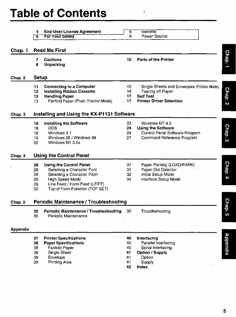
Table of Contents 4 End-User License Agreement S-For Your Safety
i6--General 6 Power Source
Chap_ 1 Read Me First
7 Cautions 10 Parts of the Printer 8 Unpacking
Chap. 2 Setup
11 Connecting to a Computer 15 Single Sheets and Envelopes (Friction Mode) 12 Installing Ribbon Cassette 16 Tearing off Paper 13 Handling Paper 17 Self Test 13 Fanfold Paper (Push Tractor Mode) 17 Printer Driver Selection
Chap. 3 Installing and Using the KX-P1131 Software
18 Installing the Software 22 Windows NT 4.0 18 DOS 24 Using the Software 18 Windows 3.1 24 Control Panel Software Program 19 Windows 95 / Windows 98 27 Command Reference Program 20 Windows NT 3.5x
Chap. 4 Using the Control Panel
28 Using the Control Panel 31 Paper Parking (LOAD/PARK) 28 Selecting a Character Font 31 Paper Out Detector 28 Selecting a Character Pitch 32 Initial Setup Mode 29 High Speed Mode 34 Interface Setup Mode 29 Line Feed / Form Feed (LF/FF) 30 Top of Form Function (TOF SET)
Chap. 5 Periodic Maintenance I Troubleshooting
35 Periodic Maintenance / Troubleshooting 35 Troubleshooting 35 Periodic Maintenance
Appendix
37 Printer Specifications 40 Interfacing 38 Paper Specifications 40 Parallel Interfacing 38 Fanfold Paper 40 Serial Interfacing 38 Single Sheet 41 Option / Supply 38 Envelope 41 Option 39 Printing Area 41 Supply
42 Index
5
6
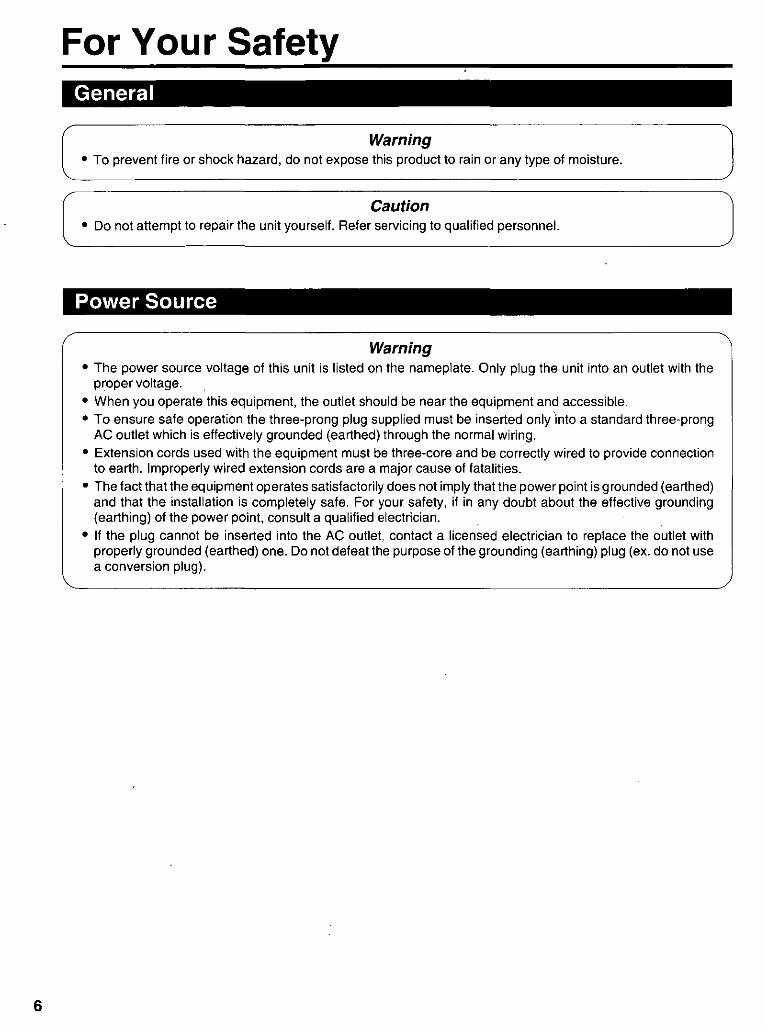
For Your Safety General
Warning • To prevent fire or shock hazard, do not expose this product to rain or any type of moisture.
Caution • Do not attempt to repair the unit yourself. Refer servicing to qualified personnel.
Power Source
Warning • The power source voltage of this unit is listed on the nameplate. Only plug the unit into an outlet with the
proper voltage.
• When you operate this equipment, the outlet should be near the equipment and accessible. • To ensure safe operation the three-prong plug supplied must be inserted only 'into a standard three-prong
AC outlet which is effectively grounded (earthed) through the normal wiring. • Extension cords used with the equipment must be three-core and be correctly wired to provide connection
to earth. Improperly wired extension cords are a major cause of fatalities. • The fact that the equipment operates satisfactorily does not imply that the power point is grounded (earthed)
and that the installation is completely safe. For your safety, if in any doubt about the effective grounding (earthing) of the power pOint, consult a qualified electrician.
• If the plug cannot be inserted into the AC outlet, contact a licensed electrician to replace the outlet with properly grounded (earthed) one. Do not defeat the purpose of the grounding (earthing) plug (ex. do not use a conversion plug).

Cautions To avoid machine malfunction, do not use the equipment under the following conditions:
~_ *0
I~
',. Dlrect exposure to sunlight • Extremely high or low temperature
[temperature range: 1 O'C to 35'C (50'F to 95'F)]
• Extremely high or low humidity (humidity range: 30% to 80% RH)
• Condensation due to rapid change of temperature
• Unstable or unlevel surrace • Liquids near the equipment
• Areas with extreme vibration
-.
• Books, paper or other items on top of the printer
• Obstruction of the printhead movement while the printer is operating
.Static Electricity Damage
• Prolonged use without allowing the printhead time to cool
• Areas of poor ventilation • Areas of high dust or chemical
fume concentration (solvent etc.)
• Without paper and a ribbon cassette installed when the printer is operating
To prevent static electricity damage to parallel/serial interrace and printhead, touch a grounded metal surrace, such as the screw on the plate cover of an electrical outlet prior to touching the interrace or printhead. (However, do not touch the printhead when it is hot.)
7
8
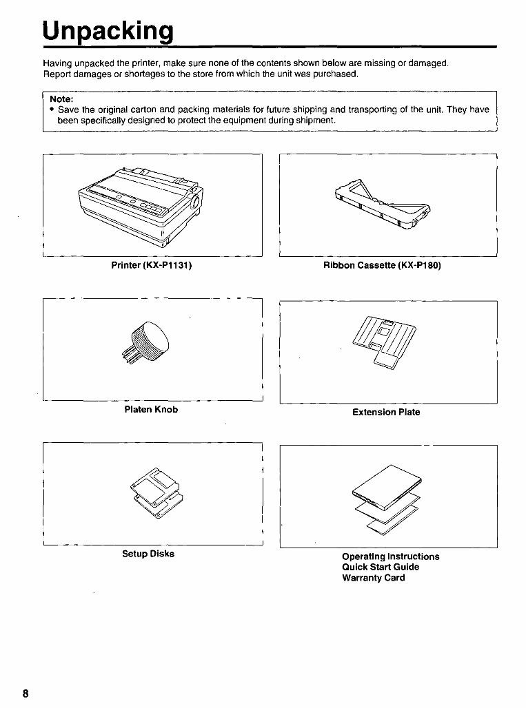
Unpacking Having unpacked the printer, make sure none of the contents shown below are missing or damaged. Report damages or shortages to the store from which the unit was purchased.
Note: • Save the original carton and packing materials for future shipping and transporting of the unit. They have
been specifically designed to protect the equipment during shipment.
Printer (KX-P1131)
Platen Knob
Setup Disks
Ribbon Cassette (KX-P180)
Extension Plate
Operating Instructions Quick Start Guide Warranty Card
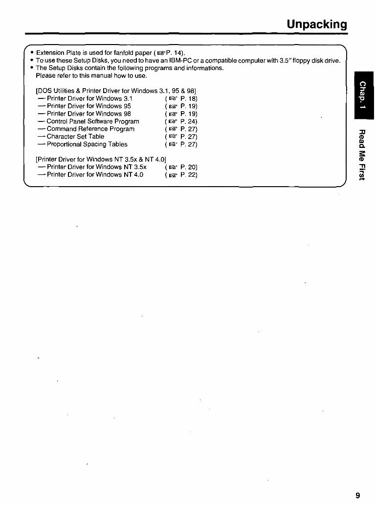
Unpacking
• Extension Plate is used for fanfold paper (I&P. 14). • To use these Setup Disks, you need to have an IBM-PC or a compatible computer with 3.5"floppy disk drive. • The Setup Disks contain the following programs and informations.
Please refer to this manual how to use.
[DOS Utilities & Printer Driver for Windows 3.1, 95 & 98] - Printer Driver for Windows 3.1 (1& P. 18) - Printer Driver for Windows 95 (1& P. 19) - Printer Driver for Windows 98 (1& P. 19) - Control Panet Software Program (1& P. 24) - Command Reference Program (1& P. 27) - Character Set Table (1& P. 27) - Proportional Spacing Tables (1& P. 27)
[Printer Driver for Windows NT 3.5x & NT 4.0] - Printer Driver for Windows NT 3.5x (1& P. 20) - Printer Driver for Windows NT 4.0 (1& P. 22)
JJ CD III Co
:s: CD
!! ia
9
10
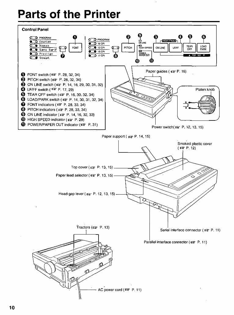
Parts of the Pri nter Control Panel
o FONT switch (1rF P. 28, 32, 34) 6 PITCH switch (1rF P. 28, 32, 34)
0:::=0 PROGRAM
~10CPI
~12CPI
i£Il15CPI
£=0 17CPI
@ ON LINE switch (1rF P.14, 16, 29, 30, 31, 32) o LF/FF switch (1rF P. 17,29) o TEAR OFF switch (1rF P. 16,30,32,34) o LOAD/PARK switch (1rF P. 14,30,31,32,34) o FONT indicators (1rF P. 28, 33, 34) o PITCH indicators (1rF P. 28, 33, 34) (1) ON LINE indicator (1rF P. 14, 16, 32, 33) ® HIGH SPEED indicator (1rF P.29) CD POWER/PAPER OUT indicator (1rF P.31)
~ '2 , rl!lI'I!I'"~i!l"l' 0 0 QNUNE I T
e PITCH r'GHSPEEoB Lm I rg:~ II ~~~~ I o ~~ROUT I 8 •. ,41,-_ I
Paper guides ( IrF P. 16)
Platen knob
Power sWitch(!IF P. 12, 13, 15)
Paper support ( IrF P. 14, 15)
Top cover (1rF P.13, 15) ___ ~:.,-
Paper feed selector (1rF P. 13, 15) --r-:::4!~'t:~(
Head gap lever (!IF P. 12, 13, 15) ---\;">~---'
Tractors (!IF P.13)
Smoked plastic cover (IrFP.12)
II
II II.
Serial intertace connector (1rF P. 11)
Parallel intertace connector (!IF P. 11)
\\\---- AC power cord (!IF P. 11)
Connecting to a Computer
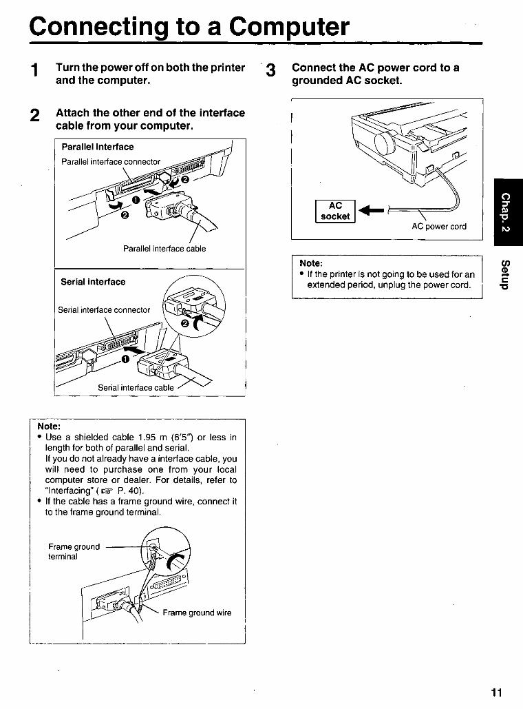
1 Turn the power off on both the printer '3 and the computer.
2 Attach the other end of the interface cable from your computer.
i
Parallel interface
Parallel interface cable
Serial interface
Note: • Use a shielded cable 1,95 m (6'5") or less in
length for both of parallel and seriaL If you do not already have a interface cable, you will need to purchase one from your local computer store or dealeL For details, refer to "Interfacing" (1lW P,40),
• If the cable has a frame ground wire, connect it to the frame ground terminaL
Frame ground terminal
L _________ '~· "m"::J
Connect the AC power cord to a grounded AC socket.
1 so~~et I+-~~~~~ AC power cord
Note: • If the printer is not going to be used for an
extended period, unplug the power cord,
11
12
Installing Ribbon Cassette
1
2
3
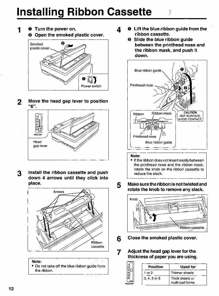
o Turn the power on. $ Open the smoked plastic cover.
Smoked plastic cover
Power switch
Move the head gap lever to position "6" .
HEAD GAP
Head gap lever
Install the ribbon cassette and push down 4 arrows until they click into place.
Note: ::], • Do not take off the blue ribbon guide from
the ribbon.
4
5
o Lift the blue ribbon guide from the ribbon cassette.
$ Slide the blue ribbon guide between the printhead nose and the ribbon mask, and push it down.
Blue ribbon guide
Printhead nose
Ribbon
Blue ribbon guide
Note: • If the ribbon does not insert easily between
the printhead nose and the ribbon mask, rotate the knob on the ribbon cassette to reduce the slack.
Make sure the ribbon is not twisted and rotate the knob to remove any slack.
Ribbon cassette _
6 Close the smoked plastic cover.
7 Adjust the head gap lever for the thickness of paper you are using.
Position Used for
1 or 2 Thinner sheets
3,4,50r6 Thick sheets or multi-part forms

Handling Paper Your Panasonic printer offers two paper feed choices: -Fanfold paper (Push tractor mode) -Single sheets and envelopes (Friction mode) "
Fanfold Paper (Push Tractor Mode)
. 1
2
o Turn the power on .
The PAPER OUT indicator will flash indicat· ing that no paper is installed in the printer.
S Adjust the head gap lever for the thickness of paper you are using.
Position Used for
1 or 2 Thinner sheets
3,4,5 or 6 Thick sheets or multi· part forms
Power switch
Set the paper feed selector to the .. D " position.
o rn D
Paper feed selector
3 Lift off the top cover.
4
~" Top cover
~ .
~
o Unlock the tractors by pulling the tractor clamping levers forward.
S Slide the tractors to accommodate the approximate width of paper being used.
5 Raise the tractor covers.
13
14
Handling Paper
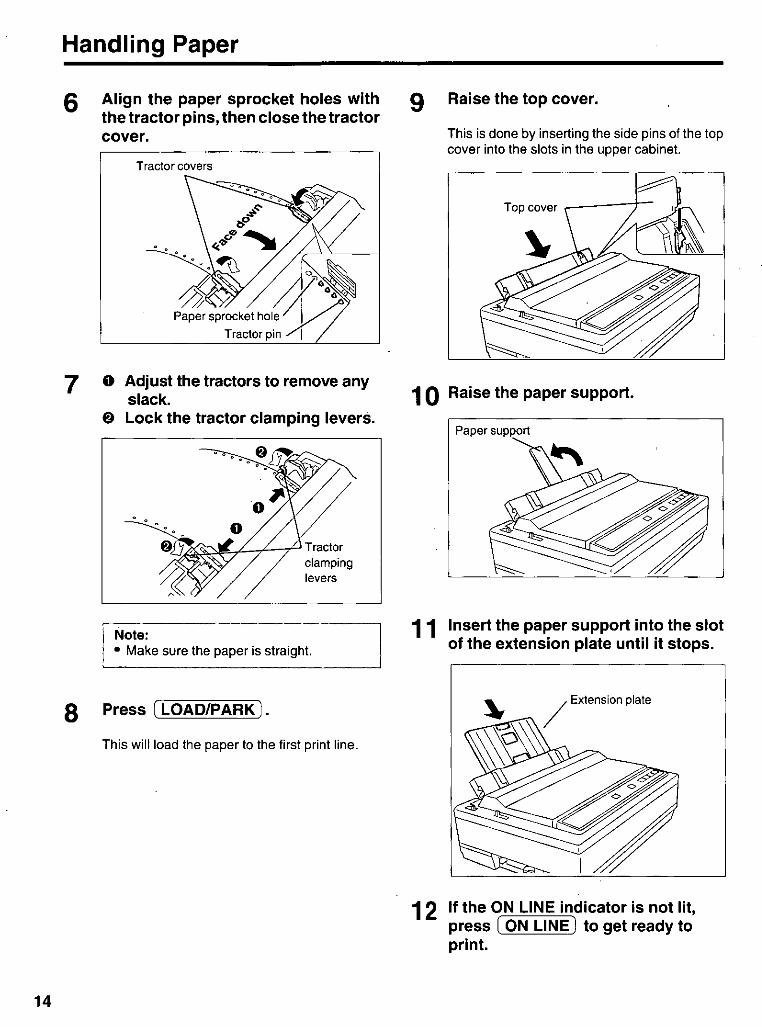
6
7
Align the paper sprocket holes with the tractor pins, then close the tractor cover.
Tractor covers
o Adjust the tractors to remove any slack.
& Lock the tractor clamping levers.
clamping levers
I Note: • Make sure the paper is straight.
8 Press [LOAD/PARK).
This will load the paper to the first print line.
9 Raise the top cover.
This is done by inserting the side pins of the top cover into the slots in the upper cabinet.
Top cover ~---)-
1 0 Raise the paper support.
11
12
Paper support
Insert the paper support into the slot of the extension plate until it stops .
If the ON LINE indicator is not lit, press I ON LINE) to get ready to print.

Handling Paper
Single Sheets and Envelopes (Friction Mode)
1
2
o Turn the power on.
The PAPER OUT indicator will flash indicating that no paper is installed in the printer.
f) Adjust the head gap lever for the thickness of paper you are using.
Position Used for
1 or 2 Thinner sheets
3,4,5 or 6 Thick sheets or envelopes
Power switch
Set the paper feed selector to the " 0 " position.
o W []
Paper feed selector
3 Raise the top cover.
This is done by inserting the side pins of the top cover into the slots in the upper cabinet.
Top cover .------t--
4 Raise the paper support.
Paper support
Note: • If the extension plate is already installed
(!BY P. 14), it does not need to be removed.
15

16
Handling Paper
5 o Separate the paper guides to the approximate width of your paper or envelope.
Note: • To predetermine your left most print
position, move the left paper guide until it clicks into place.
e Insert a sheet of paper through the paper guides.
The paper will be automatically loaded to the first print line.
Tearing off Paper
6
Note: l • To disable Auto Loading, turn it OFF in the I
INSTALL Menu on your Setup Disk (1& P. 24-26) or by using the Control Panel ( 1& P. 32-33).
• If Auto Loading is disabled, you must press I LOAD/PARi{) to load paper.
• If you need to align the paper horizontally or vertically, set the paper feed selector to " 0 ". This releases the paper and allows the paper to be positioned manually as required. Set the selector back to " 0 .. before printing.
If the ON LINE indicator is not lit, press ION LINE I to get ready to print.
With fanfold paper installed, this function allows you to advance your paper to the tear position. After tearing off the page you can return your paperto the first printer line by pressing I TEAR OFF) again. If I TEAR OFF) is not pressed a second time, the printer will automatically reverse to the first print line upon receiving data from the computer.
1 Press I TEAR OFF I to advance the paper to the tear position.
2 Tear off the page.
3 Press I TEAR OFF I to reverse the paper back to the first print line.
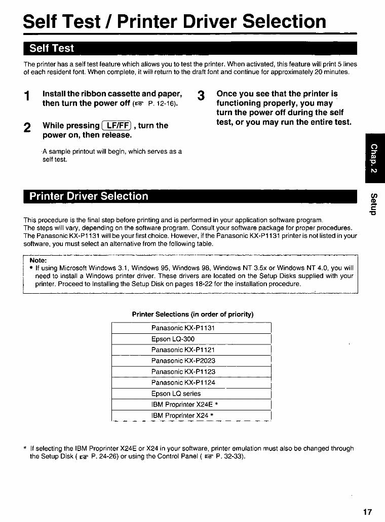
Self Test I Printer Driver Selection Self Test
The printer has a self test feature which allows you to test the printer. When activated, this feature will print 5 lines of each resident font. When complete, it will return to the draft font and continue for approximately 20 minutes.
1 Install the ribbon cassette and paper, then turn the power off (OF P.12-16).
3 Once you see that the printer is functioning properly, you may
2 While pressing ( LF/FF) , turn the power on, then release.
turn the power off during the self test, or you may run the entire test.
·A sample printout will begin, which serves as a self test.
Printer Driver Selection
This procedure is the final step before printing and is performed in your application software program. The steps will vary, depending on the software program. Consult your software package for proper procedures. The Panasonic KX-Pl131 will be your first choice. However, if the Panasonic KX-Pl131 printer is not listed in your software, you must select an alternative from the following table.
Note: • If using Microsoft Windows 3.1, Windows 95, Windows 98, Windows NT 3.5x or Windows NT 4.0, you will
need to install a Windows printer driver. These drivers are located on the Setup Disks supplied with your printer. Proceed to Installing the Setup Disk on pages 18-22 for the installation procedure.
Printer Selections (in order of priority)
Panasonic KX-Pl131
Epson LQ-300
Panasonic KX-Pl121
Panasonic KX-P2023
Panasonic KX-Pl123
Panasonic KX-Pl124
Epson LQ series
IBM Proprinter X24E •
IBM Proprinter X24 •
* If selecting the IBM Proprinter X24E or X24 in your software, printer emulation must also be changed through the Setup Disk ( OF P. 24-26) or using the Control Panel ( OF P. 32-33).
17

18
Installing the Software These Setup Disks (DOS Utilities & Printer Driver for Windows®3.1, 95 & 98 disk, Printer DriverforWindows NT® 3.5x & 4.0) can only be used in an IBM-PC or a compatible computer with a 3.5" floppy disk drive.
Before using the Setup Disk, it is recommended that you make a back-up copy and store the original in a safe place.
The following steps will automatically create a directory called P1131 and copy Control Panel Software (CPS1131.EXE) and Command Reference utility (CMDREF.EXE) from the DOS Utilities & Printer Driver for Windows® 3.1, 95 & 98 disk to your C Drive. (You can change the directory and drive.)
N~: J • Control Panel Software and Command Reference utility cannot be installed on Windows NT.
-
Program Function
Control Panel Software Allows you to view and change the printer settings on the computer screen.
Command Reference utility Allows you to access a detailed explanation of each software command on the computer screen.
Follow the steps below for installation.
1 Insert the DOS Utilities & Printer Driver for Windows® 3.1, 95 & 98 disk into drive A (or B).
2 Type A: (or B:) and press (Enter).
Windows 3_1
Program
3
4
Printer Driver A printer driver is the part
Type SETUP and press centerJ.
Follow the instructions on your computer screen.
Function
of the software that allows the software to communicate with the printer via the interface in use.
Control Panel Software Allows you to view and change the printer settings on the computer screen.
Command Reference Allows you to access a detailed explanation of each software command on the utility computer screen.
Follow the steps below for installation.
1
2
Insert the DOS Utilities & Printer Driver for Windows® 3.1,95 & 98 disk into drive A (or B).
Click I File I from the Program Manager window.
3
4
5
Click I Run ... 1 .
Type A:\ SETUP (or B:\ SETUP) and then press (Enter) (or click 10K 1>.
Follow the instructions on your computer screen.
Installing the Software
Windows 951 Windows 98
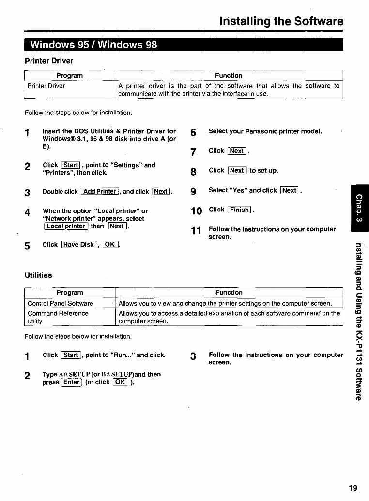
Printer Driver
Program Function
Printer Driver A printer driver is the part of the software that allows the software to communicate with the printer via the interface in use.
Follow the steps below for installation.
1
2
3
4
5
Insert the DOS Utilities & Printer Driver for Windows® 3.1, 95 & 98 disk into drive A (or B).
Click 1 Start 1 , point to "Settings" and "Printers", then click.
Double click 1 Add Printer I, and click 1 Next I.
When the option "Local printer" or "Network printer" appears, select 1 LocalJ)rinter 1 then 1 Next I.
Click 1 Have Disk I, 10K I.
Utilities
Program
6 Select your Panasonic printer model.
7 Click 1 Next I.
8 Click 1 Next 1 to set up.
9 Select "Yes" and click 1 Next I.
10 Click 1 Finish I.
11 Follow the instructions on your computer screen.
Function
Control Panel Software . Allows you to view and change the printer settings on the computer screen.
Command Reference Allows you to access a detailed explanation of each software command on the utility computer screen.
Follow the steps below for installation.
1 Click 1 Start I, point to "Run ... " and click.
2 Type A:\ SETUP (or B:\ SETUP)and then press ( Enter) (or click 10K 1 ).
3 Follow the instructions on your computer screen.
:::I (Q
III :::I Co c: en :::I (Q ... ~ CD
~ "tI ... ... w ...
19

20
Installing the Software
Windows NT 3.5x
Program Function
Printer Driver A printer driver is the part of the software that allows the software to communicate with the printer via the interface in use.
Single Users
If you do not have a network connection or do not plan to share the printer with others on the network, perform the following.
1
2
3
4
Double click the Main icon in the Program Manager to display the "Main" window.
Double click the Print Manager icon to display the "Print Manager" window.
Click "Printer" menu, and "Create Printer ... ".
Enter the printer name (ex. "Panasonic KX-P1131 ") in the "Printer Name" box ..
Crellte Prmter
Prinhn li-: IpanasorMc KX.p1131
1·1
r-I Il.rivel: ~~~~~~~~ D ,Rscliption: ~
P,inllo: "ILP,,-Tl,-, _____ ----""
[ 0 ~h.,. Ohi ... i"'~ ~ Oh. ~'.m'
S~'O Name: :
L.oc,,!ion: I II I
leoK II' Cencel
II Solyp ...
II Detail •...
I[setlin.!ll ...
Help
I I
5
6
7
8
9
Click the "Driver" box, and "Other ... ".
Insert the Printer Driver for Windows NT® 3.Sx & NT® 4.0 disk into disk drive A.
Click I OK I.
Click lOKI.
Click 10K I.
1 0 Click I OK I .
Printer Setup
Forms--------~
IL n9_K _] II Cancel I
Name If-talJ!oneonl
c:1 L:=:elc:le.:.-, _____ ----"II±"'g II Help
II Aboul... I
Installing the Software
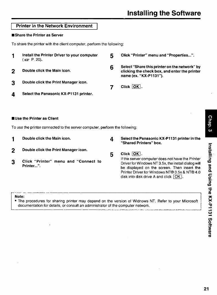
Printer in the Network Environment
.Share the Printer as Server
To share the printer with the client computer, perform the following:
1
2
3
Install the Printer Driver to your computer (1& P.20).
Double click the Main icon.
Double click the Print Manager icon.
4 Select the Panasonic KX-P1131 printer .
• Use the Printer as Client
5
6
7
Click "Printer" menu and "Properties ... ".
Select "Share this printer on the network" by clicking the check box, and enter the printer name (ex. "KX-P1131 ").
Click 10K I.
To use the printer connected to the server computer, perform the following:
1
2
3
Double click the Main icon.
Double click the Print Manager icon.
Click "Printer" menu and "Connect to Printer ... ",
Note:
4
5
Selectthe Panasonic KX-P1131 printer in the "Shared Printers" box.
Click 10K I. If the server computer does not have the Printer Driverfor Windows NT 3.5x, the install dialog will be displayed on the screen. Then insert the Printer Driver for Windows NT® 3.5x & NT® 4.0 disk into disk drive A and click I OK I.
• The procedures for sharing printer may depend on the version of Widnows NT. Refer to your Microsoft documentation for details, or consult an administrator of the computer network.
:::I
~. :::I
CQ
III :::I Q.
c: !!!. :::I
CQ
21
-:T CD
" X , "tI ..... ..... Co) ..... CJ)
~ iil

22
Installing the Software
Windows NT 4.0
Program Function
Printer Driver A printer driver is the part of the software that allows the software to communicate with the printer via the interface in use.
Single Users
If you do not have a network connection or do not plan to share the printer with others on the network, perform the following.
1 Click IStart I, point to "Settings" and click 7 Insert the Printer Driver for Windows NT® "Printers", 3.5x & NT® 4.0 disk into disk drive A.
2 Double click the Add Printer icon. a Click I OK I.
3 Click INext> I. 9 Click I Next> I four times.
4 Select "LPT1:" by clicking on the check box. 10 Click I Finish I.
5 Click I Next> I. The printer test page will be printed out.
6 Click I Have Disk ... I. 11 Click I YES I.

Installing the Software
Printer in the Network Environment
• Share the Printer as Server
To share the printer with the client computer, perform the following:
1 Install the Printer Driver to your computer 5 Click "File" menu and .. Sharing ...... ( 1& P. 22).
6 Click "Shared". 2 Double click the My Computer icon.
7 Enter the printer name (ex. "KX-P1131").
3 Double click the Printers icon.
8 Click 1 OK I. 4 Select the Panasonic KX-P1131 printer.
.Use the Printer as Client
To use the printer connected to the server computer, perform the following:
1
2
3
Double click the Add Printer icon.
Select "Network printer server".
Click 1 Next> I.
Note:
4
5
Select the Panasonic KX-P1131 printer in the "Shared Printers" box.
Click 1 OK 1 and follow the instruction on the screen. If the server computer does not have the Printer Driver for Windows NT 4.0, the install dialog will be displayed on the screen. Then insert the Printer Driver for Windows NT® 3.5x & NT® 4.0 disk into disk drive A and enter the path name "A:INT40", then click 1 OK I.
• The procedures for sharing printer may depend on the version of Widnows NT. Refer to your Microsoft . documentation for details, or consult an administrator of the computer network. ------------ ----.----------- -----.----- -.----
:::I !e-m
:::I IQ m :::I Co c: !!!. :::I
IQ -:::T (1)
" X , "tI ... ... (.,) ... (J) o
~ iil
23
24
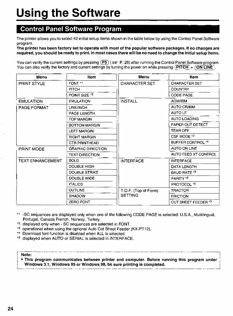
Using the Software Control Panel Software Program
The printer allows you to select 42 initial setup items shown in the table below by using the Control Panel Software program. The printer has been factory set to operate with most of the popular software packages. If no changes are required, you should be ready to print. In most cases there will be no need to change the initial setup items.
You can verify the current settings by pressing I F5) (.,... P. 26) after running the Control Panel Software program. You can also verify the factory and current settings by turning the power on while pressing I PITCH) + ION LINE).
Menu Item Menu Item
PRINT STYLE FONT -1 CHARACTER SET CHARACTER SET
PITCH COUNTRY
POINT SIZE -2 CODEPAGE
EMULATION EMULATION INSTALL AGM/IBM
PAGE FORMAT LINE/INCH AUTOCR/IBM
PAGE LENGTH AUTO LF
TOP MARGIN AUTO LOADING
BOTTOM MARGIN PAPER OUT DETECT
LEFT MARGIN TEAR OFF
RIGHT MARGIN CSF MODE-3
CTR PRINTHEAD BUFFER CONTROL -4
PRINT MODE GRAPHIC DIRECTION AUTO ON LINE
TEXT DIRECTION AUTO FEED XT CONTROL
TEXT ENHANCEMENT BOLD INTERFACE INTERFACE DOUBLE HIGH DATA LENGTH DOUBLE STRIKE BAUD RATE-s
DOUBLE WIDE PARITY -5
ITALICS PROTOCOL -5
OUTLINE T.O.F. (Top of Form) TRACTOR SHADOW SETTING FRICTION
ZERO FONT CUT SHEET FEEDER -3
'1 ·SC sequences are displayed only when one of the following CODE PAGE is selected: U.S.A., Multilingual, Portugal, Canada French, Norway, Turkey. .
'2 displayed only when· SC sequences are selected in FONT. '3 operational when using the optional Auto Cut Sheet Feeder (KX·PT12). '4 Download font function is disabled when ALL is selected. '5 displayed when AUTO or SERIAL is selected in INTERFACE.
r Note: .---------- -----.-.--------.------.--.---.
II • This program communicates between printer and computer. Before running this program under Windows 3.1, Windows 95 or Windows 98, be sure printing is completed. I L-- _____________ __. __ _ ___ ~

To recall the programs, follow the steps below.
<DOS>
1* At your C:lprompt,
2
type CD PI 131 and press [Enter) .
Type CPS1131 and press [EiitefJ .
<Windows 3.1 >
1 Select I Run I from the File menu.
2 Type C:\P113I\CPS1131 and press [Enter) (or click 10K I).
Using the Software
<Windows 95 and Windows 98>
1 Click I Start I , point to "Run ... " and click.
2 Type C:\P113I1CPS1131 and press [Enter 1
. (or click 10K I) . • If you changed the directory when installing utilities for DOS, select your changed directory and press [ Enter I .
. _--------- --- ---~- ------ ---_._-----Note: • If you want to run the Control Panel Software program using the Setup Disk, follow the steps below.
1. Insert your DOS Utilites & Printer Driver for WindowS® 3.1, 95 & 98 disk into drive A (or B).
<DOS> <Windows 3.1> <Windows 95 and Windows 98>
2. 0 Type A: (or B:) and press CEnter) .
2. 0 Select I Run I from the File 2. 0 Click I Start I , point to menu. "Run ... " and click.
o Type CD DOS and press [Enter).
o Type A:IDOSICPSII31 0 Type A:IDOSICPSII31 (or B:IDOSlCPSI131). (or B:IDOSICPSI131).
E) (Type jPS1131 and press L Enter. E) Press (Enter 1 E) Press (Enter 1 I
_____ (~r CliC~ I~~I~ _____________ (~r_cli,,~_1 OK I)· ___ -.-J
3 The first screen is an introduction to the operation of the Control Panel Software program. Please read it through and press any key to continue. (If your display is monochrome, press "M" key.)
« Control Panel Software (xxxxxxxxxx) »
;= <Menu>
[~~~~' ~I * PRINT STYLE *EMULATlQN *PAGE FORMAT *PRINTMODE * TEXT ENHANCEMENT * CHARACTER SET *INSTALl *INTERFACE * T.O.F. SETIING
« COMMENT» Select print style.
«KEY OPERATlON»
1F1~HElPI IF3~SAVE TO DISKI 1F5~PRINT SETTINGS] 1F6~L1ST] [FMACTORY SETTINGS] [F4~LOAD FROM DISK] 1F1O~SEND TO PRINTER) [ESC~EXIT]
4 The <Menu> window will be highlighted.
:::I (Q
III :::I C.
c: !!!. :::I
(Q -~ ID
" X , "tI .... .... Co) .... en
~ .. ID
25

26
Using the Software
~ --~~~~--------~ --~---·~--~·--·~l Note: You can proceed through the Control Panel Software program using a computer mouse or your arrow keys.
Using the keyboard: . • (TAB I / ( SHIFT I + (TAB I to move the cursor I • 00 / (I) to move within the current window. in [SAVE TO DISK] and [LOAD FROM DISK]
• ~ to advance to <Item> and <Selting> windows.
• (Enter I to make selection in <Setting> window. lWindOWS.
Using the mouse:
• Highlight the selection and click the left mouse button. • (B to return to the previous window.
- --~----~--.
F1 HELP displays explanation of the functions F2 -1 FACTORY SETTINGS resets to the factory settings
F3 SAVE TO DISK saves the setting as a file-2 to the Disk
F4 LOAD FROM DISK loads your desired setting saved using (fID from the Disk F5 -3 PRINT SETTINGS prints out the current settings
F6 LIST displays the current setting list
F10 -3 SEND TO PRINTER sends the settings to the printer
ESC EXIT exits the Control Panel Software program
-1 If you want to reset the printer settings to the factory settings when using the Control Panel Software program, press ( F2) to recall the factory settings and then press (F1 0) to send the settings to the printer.
-2 "* .DAT' appears in the File Name position. Delete the * and enter a file name (up to 8 characters). -3 When sending the data through the Serial Interface (or Parallel Interface), change the option items (INTERFACE
and PORT) to the required setting. (ex; INTERFACE) 1. Press ctJ to highlight PARALLEL (or SERIAL) and press (EirteiJ. 2. Press 00 to highlight SERIAL (or PARALLEL) and press (Enter).

Using the Software
Command Reference Program The Command Reference program allows you to access a detailed explanation of each software command on the screen. Each displayed explanation can be printed out if required.
Note: • You can print the Character Set Tables. On the SELECT COMMAND screen, press ©. Then select your
desired table and press lful!riJ. • If 7 bit is selected for Data Length, you cannot print the command lists and character set tables. • There is a list of Proportional Spacing Tables after the software commands lists. If you want to see a
proportional spacing table, select your desired table and press I Enter) . l ___ ~ _________________ . __
To recall the programs, follow the steps below.
<DOS> <Windows 3.1> <Windows 95 and
1" At your C:\prompt, 1 Select I Run I from the File Windows 98> Cpe Cj PI 131 and press menu. 1 Click I Start I , point to
Enter. "Run ... " and click.
2 Type C:IPI 13IICMDREF 2 Type C:1P1I31ICMDREF 2 Type CMDREF and press and press I Enter) . and press I Enter I
CEil@. (or click 10K I). (or click 10K I).
* If you changed the directory when installing utilities for DOS, select your changed directory and press I Enter I. i Note:' - -. -_.. --- --." - .. - - ....... - .-. --.-_.-.... -_. -- -.-------
• If you want to run the Command Referece program using the Setup Disk, follow the steps below.
1. Insert your DOS Uti lites & Printer Driver for Windows® 3.1, 95 & 98 disk into drive A (or 8).
<DOS>
2. 0 (ype I' (or B:) and press Enter.
e (ype Cj DOS and press Enter.
<Windows 3.1 >
2. 0 Select I Run I from the File menu.
e Type A:\DOs\CMDREF (or B:\DOS\CMDREF).
<Windows 95 and Windows 98>
2. 0 Click I Start I , pOint to "Run ... " and click.
e Type A:\DOs\CMDREF (or B:\DOS\CMDREF).
@) Click OK (or pre'':'s'='s''''''E=nt'-:e'''r ).
@) Click I OK I (or press [Enter)). I @) (ype CiDREF and press
I Enter . l... _
3
4
5
The first screen is an introduction to the operation of the Command Reference program. Please read it through and press any key to continue. (If your display is monochrome, press "M" key.)
Select the desired emulation and press I Enter) (or click 10K I). The commands list will be displayed.
Select the desired command and press [ Enter) (or click I OK I). The detailed explanation of the command will be displayed.
6 Press (]J to exit Command Reference.
« Panasonic KX-P1131 command reference utility (xxxxxxxxxx) »
- -SELECT EMULAnON --
EPSON IBM
[TI/[l) [Enter] [E)
: Select emulabon : Set emutaton : Exit Command Reference
:::I !e-III
:::I IC III :::I Co c: 21. :::I
IC -::T (I)
" >< , "'C ... ... Co) ... CJ)
i iil
27

28
Using the Control Panel Selecting a Character Font
This printer contains resident fonts which are accessible through the Control Panel. You can select anyone of the character fonts by pressing the FONT switch on the Control Panel.
FONT indicators 0=:0 PROGRAM cd (~ courier
o=e,Rom.n S '. .) Sans Serif FONT j:::::::J) Prestige
0= ~ 5 CII.i.p.t
'"
=B = PROGRAM Roman
-::0 B = Courier c· EJ = Sans Serif
e=light is lit o=light is out .. =Iight is blinking
• Press and release ( FONT).
The combination of FONT indicators indicates the current character font selected, as shown on the Control Panel.
.:=oEJ = Prestige
r --.---- - -----~- -- - --- -- --- --- - -- ----- - ------ - ----------- -----------:J---Note:
! . You must be in PROGRAM (both FONT indicators are off) to allow your software to control your font selection_
---- -- -- --~- ---- ----,--,- -- --------------
Selecting a Character Pitch This printer contains resident pitches which are accessible through the control panel. You can select anyone of the character pitches by pressing the PITCH switch on the control panel.
PITCH indicators ~PROGRAM ~ ~10CPI
~) 12CPI ;gITCH ~)15CPI
~17CPI
""
a=o I PITCH I = PROGRAM 0=., I PITCH I = 12 CPI
-=0 I PITCH I = 10 CPl .=. 1 PITCH I = 15 CPI
e=light is lit o=light is out .. =Iight is blinking
• Press and release [ PITCH) .
The combination of PITCH indicators indicates the current character pitch selected, as shown on the Control Panel.
_::0 I PITCH I = 17 CPI
iN~t~~------- ------- ------ ------- --- --------- --------l i • You must be in PROGRAM (both PITCH indicators are off) to allow your software to control your pitch I !_, _se~~c~~~______ ____ ____ _ __ _ _ __ ____ _ _ _ __ _ ____________ J

Using the Control Panel
High Speed Mode The High Speed mode is a feature for doubling the print speed only when La Font and one of the 120 dpi, 180 dpi or 360 dpi of 24-pin bit image are selected.
r-------·------·-----Note: lo When enabled, this feature will lower the print density.
Turning on the High Speed mode:
~EAR ~OAD OFF PARK L...>"--'
Turning off the High Speed mode:
~~ ~~
Line Feed I Form Feed (LF/FF)
----~
While pressing ION LINE), press I LFIFF).
The HIGH SPEED indicator is on.
While pressing ION LINE ), press( LF/FF ).
The HIGH SPEED indicator is off.
You can adjust the paper position by using the front panel switches when the printer is in the OFF LINE mode or when the printer is not printing in the ON LINE mode.
B LFIFF ~~ ~~
With paper installed, pressing ( LFIFF) once advances the paper one line.
With paper installed, holding I LFIFF) moves the printhead to the center and advances the paper to the top of the next page.
1------------·--- -.-- ------------------ .------::l . Note: i ° When pressing ( LFIFF) , the amount of paper which is fed is determined by the current setting for lines per
I inch as specified through the Control Panel Software program, control panel (Initial Setup mode) or your I
. application software. J --~ - - ----- - ---~~~--------- ------ --- - ---- --.. - .---~--- -- ---- --- ------- ----
c: In :::l
(C -:::r <D o o :::l -o "tI III :::l !e.
29
30
Using the Control Panel
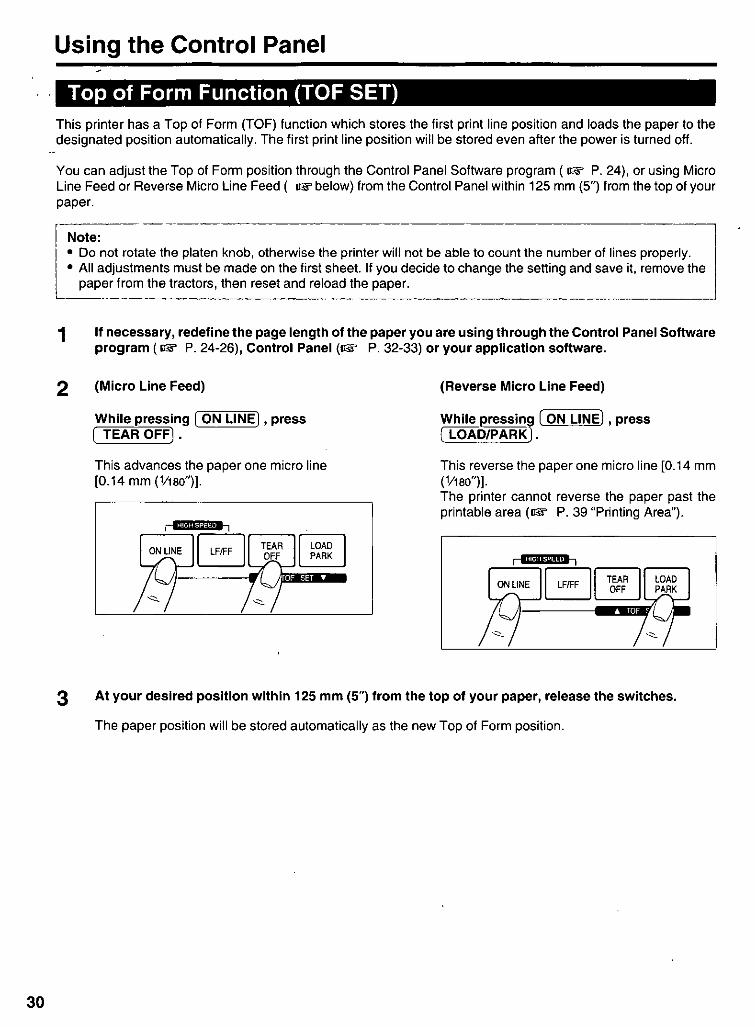
Top of Form Function (TOF SET) This printer has a Top of Form (TOF) function which stores the first print line position and loads the paper to the designated position automatically. The first print line position will be stored even after the power is turned off.
You can adjust the Top of Form position through the Control Panel Software program (IJW P. 24), or using Micro Line Feed or Reverse Micro Line Feed ( IJW below) from the Control Panel within 125 mm (5") from the top of your paper.
r Note:--• Do not rotate the platen knob, otherwise the printer will not be able to count the number of lines properly . • All adjustments must be made on the first sheet. If you decide to change the setting and save it, remove the
paper from the tractors, then reset and reload the paper.
1 If necessary, redefine the page length of the paper you are using through the Control Panel Software program (IJW P. 24-26), Control Panel (IJW P. 32-33) or your application software.
2 (Micro Line Feed)
While pressing ( ON LINE] , press ( TEAR OFF].
This advances the paper one micro line [0.14 mm (V1BO")].
~ ~
(Reverse Micro Line Feed)
While pressing ( ON LINE] , press (IOA"DIPARK) .
This reverse the paper one micro line [0.14 mm (V1BO")]. The printer cannot reverse the paper past the printable area (IJW P. 39 "Printing Area").
BFIFF OOEAR OFF L../'--...J
3 At your desired position within 125 mm (5'1 from the top of your paper, release the switches.
The paper position will be stored automatically as the new Top of Form position.

Using the Control Panel
Paper Parking ~ This function moves the fanfold paper to the park position, enabling you to use single sheets or envelopes without removing or wasting your fanfold paper.
1
2
3
Tear off the printed page(s) of the fanfold paper being used (I@" P. 16).
Press (LOAD/PARK) to reverse the fanfold paper to the park position.
o Move the paper feed selector to " 0 " (Friction Mode).
f) Load single sheets or envelopes.
When you have finished printing, remove the sheet (or envelope) from the printer.
o o W o
Paper Out Detector
4
5
Move the paper feed selector to " 0 " (Tractor Mode).
o rn o
Paper feed selector
Press (LOAD/PARK) to reload the fanfold paper to the first print line.
Your printer has a paper out detector. When an out of paper condition occurs, printing stops, the printer goes to the OFF LINE mode, and the POWER/PAPER OUT indicator starts blinking. To continue printing to the end of the current page, follow the steps below.
1 Press (ON LINE) repeatedly until the page is completed.
3 If the ON LINE indicator is not lit, press (ON LINE ).
2 Insert the new paper ( I@" P. 13-16).
:-N~te;-- ----- ------ .-- ---- ----.- .-. '-- - - -- -- -- ------ - .------- --------]
I
. When PAPER OUT DETECT is set to ON (I@" P. 33), printing stops at 1.26 mm (0.5") from the bottom of 'I
the paper. , • The paper out detector can be disabled through the Control Panel Software program ( I@" P. 24). I
L____ ___ ____ __ _ . __ ._ . ____ .____ . _ _ _ _ .. ___ . __ . __ _ _ _ _ ___ _ .. ___ ----'
c !!!. ::l
CQ -:7 CD o o ::l -(3
"C III ::l !.
31

32
Using the Control Panel
Initial Setup Mode The 19 features (items) can be set in the Initial Setup mode through the Control Panel. For the features and the indicators condition, refer to page 33. These features can also be set through the Control Panel Software program ( OW P. 24).
1
2
3
Load a sheet of paper (OW P. 13-16), and turn the power off.
While pressing (LOAD/PARK) , turn the power on to enter the Initial Setup mode.
Both FONT indicators and the HIGH SPEED indicator will be blinking. The current settings will be printed automatically.
Press and release (FONT) and [ON LINE) to select the item.
Each time you press ( FONT) and [ON LINE ), you will advance to the next item. Select the desired item according to the status of the FONT and ON LINE indicators (on, off, blinking) (ow P.33).
FONT indicators ON LINE indicator
= 'ROO"" (' 1 1-=0 Courier OlH'NE ~: Roman c:::J
• -=0 Prest ige ~R o=J' SCI\4l-t P","EAOUf
~ "'"
4
5
Press and release [PITCH) to set the item's status.
The item's status will change each time you press (PITCH) (ow P.33). To change additional settings, repeat step 3 and 4.
PITCH indicators o=g PROGRAM 0 CLQl10CPI
~12CPI !f'TCH (~15CPI
rL9 17CPI
"-
Press ( LOAD/PARK) to exit the Initial Setup mode.
FONT indicator will go off and the current conditions will print.
i Note: • To return all current settings to the factory
settings, follow the steps below. 1. While pressing [TOAD/PARK). turn the
i power on, then release . I 2. Press [ TEAR OFF). I 3. Press [ LOADJPARK) to exit the Initial Setup I mode. L ___________ ~ _____ ._
Using the Control Panel
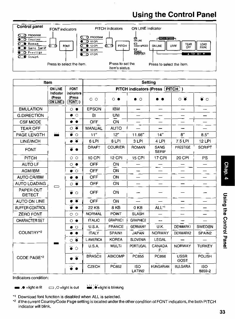
Control panel FONT indicators PITCH indicators ON LINE indicator
g PROGRAM Q 0=:::0 PROGRAM Q l' rl;Ua;I@#!:!u.,
Courier ~ -=::0 10CPI ~ ONUNE ~B@]~ 0::=- Roman FONT 0=::::::. 12 CPI PITCH ~GH SPEED ON LINE LFIFF TO~: LpOAARKD <LIl Sans Serif ~ 15CPI C
-==0 Prestige ~ 17CPI ~ARbUT I Wi.i4iii_ ~ScM.pct ~
Press to select the item. Press to set the Press to select the item. item's status.
Item Setting
ON LINE FONT PITCH indicators (Press (PITCH I ) indicator indic.ators (Press (Press o 0 O. • 0 • • O. .0
(ON LINE) (FONT) )
EMULATION o • EPSON IBM - - - -G.DIRECTION
• 0 BI UNI - - - -
CSFMODE • • OFF ON - - - -.',
TEAR OFF o • MANUAL AUTO - - - -
PAGE LENGTH '" • 0 11" 12" 11.66" 14" 8" 8.5" -LINE/INCH .',
6 LPI 8 LPI 3 LPI 4 LPI 7.5 LPI 12 LPI • • FONT ." DRAFT COURIER ROMAN SANS PRESTIGE SCRIPT • • SERIF
PITCH 0 0 10 CPI 12 CPI 15 CPI 17 CPI 20CPI PS
AUTO LF o • OFF ON - - - -
AGM/IBM • 0 OFF ON - - - -
AUTOCR/IBM • • OFF ON - - - -AUTO LOADING
.', OFF ON o • - - - -
= PAPER OUT ." OFF ON DETECT • 0
- - - -
AUTO ON LINE •• OFF ON - - - -
BUFFER CONTROL ." • • 22 KB 8 KB OKB ALL-' - -
ZERO FONT 0 0 NORMAL POINT SLASH - - -CHARACTER SET o • ITALIC GRAPHIC1 GRAPHIC2 - - -
• 0 U.S.A. FRANCE GERMANY U.K. DENMARK1 SWEDEN
COUNTRy-2 • • ITALY SPAIN1 JAPAN NORWAY DENMARK2 SPAIN2 .', L.AMERICA KOREA SLOVENIA LEGAL 0 • - -- ." U.S.A. MULTI PORTUGAL CANADA NORWAY TURKEY • 0 F.
CODE PAGE-2 .', BRASCII ABICOMP PC855 PC866 USSR POLISH • • GOST .', CZECH PC852 ISO HUNGARIAN BULGARIA ISO • • LATIN2 8859-2
Indicators condition:
_ ,. ;Iight is lit = ,0 ;light is out , I I , I F
_ , • ;Iight is blinking
-, Download font function is disabled when ALL is selected. -2 If the current Country/Code Page setting is located under the other condition of FONT indicators, the both PITCH
indicator will blink.
-:::T CD o o :::l -a "tJ III :::l ~
33
34
Using the Control Panel
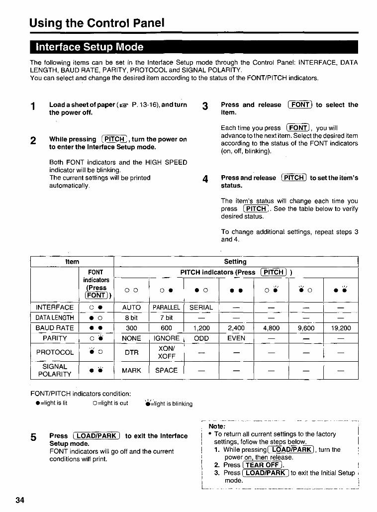
Interface Setup Mode The following items can be set in the Interface Setup mode through the Control Panel: INTERFACE, DATA LENGTH, BAUD RATE, PARITY, PROTOCOL and SIGNAL POLARITY. You can select and change the desired item according to the status of the FONT/PITCH indicators.
1
2
Load a sheet of paper (1& P. 13-16), and turn the power off.
While pressing (PITCH), turn the power on to enter the Interface Setup mode.
Both FONT indicators and the HIGH SPEED indicator will be blinking. The current settings will be printed automatically.
Item
3
4
Press and release (FONT) to select the item.
Each time you press (FONT), you will advance to the next item. Selectthe desired item according to the status of the FONT indicators (on, off, blinking).
Press and release I PITCH) to set the item's status.
The item's status will change each time you press (PITCH ). See the table below to verify desired status.
To change additional settings, repeat steps 3 and 4.
Setting
FONT PITCH indicators (Press (PITCH) ) indicators (Press '" .. , '" (FONT))
00 o • • 0 • • o • • 0 • • INTERFACE o • AUTO PARALLEL SERIAL - - - -DATA LENGTH .0 8 bit 7 bit - - - - -BAUD RATE • • 300 600 1,200 2,400 4,800 9,600 19,200
PARITY O. NONE IGNORE ODD EVEN - - -
", XON/ PROTOCOL
• 0 DTR - - - - -
XOFF
SIGNAL .'. MARK SPACE POLARITY • • - - - - -
FONT/PITCH indicators condition: • =Iight is lit o =light is out 'e'~light is blinking
5 Press I LOAD/PARK) to exit the Interface Setup mode. FONT indicators will go off and the current conditions will print.
~ ~~~-~e:rn all curr~~:et~ngs ~~ ~h~ f~:ory--' --I settings, follow the steps below. I 1. While pressing I LOAD/PARK), turn the I
power on, then release. I
2. Press ( TEAR OFF). I 3. Press ( LOAD/PARK I to exit the Initial Setup I
I mode. I L ___ . _____ , ___ ~ _______________ . __________ :

Periodic Maintenance I Troubleshooting Periodic Maintenance
The printer does not require routine maintenance. However, reasonable care of the printer will extend its life. The following periodic measures are recommended:
• Cleaning the unit is the most important action you can perform. The frequency of cleaning is dependent upon the environment. - Turn the power off and unplug the AC power cord.
- Clean the case and covers with a soft cloth. Use any mild commercial cleaner on the cloth, do not spray directly on to the printer.
- Raise the top cover and pull up the roller cover. Vacuum or dust the inside area of the unit. Be very careful not to damage the printhead ribbon cable or the carriage drive belt.
! Caution: ·-----1 i • The printhead may be hot, use caution J ' when the cover is open. L. _. _________ ........... _ ... _
Troubleshooting
- The platen should be cleaned with denatured alcohol only.
- The carriage guide bar can be lubricated with a very light oil. Contact your Authorized Panasonic Service Center for advice when lubrication will be needed.
Ribbon Cassette
i-N~t;:- -.-.. -.-~ ! • If the ribbon begins to catch, snag, or tear from I the printhead, your printer requires servicing. L..__ .__.
Most problems associated with the printer can be traced to improper setup, installation, or cabling. The following table will assist you in identifying and correcting some of the more common problems. If you need additional help, contact the reseller from which the unit was purchased or the Panasonic technical support number fou'nd in P. 2 of this manual.
Symptom Possible Cause Probable Solution
Ink smears Head gap lever is not in the Move the lever toward the position "6".until ink proper position doesn't smear (1& P. 12)
Printout is faint Head gap lever is not in proper Adjust the lever to the proper pOSition position (1& P. 12, 13, 15)
Printhead moves but there is Ribbon is not installed Re·insert ribbon (1& P. 12) no printing correctly
Paper out detector inoperative PAPER OUT DETECT is OFF Sel PAPER OUT DETECT to ON (1& P. 24, 31)
Printer does not power up No AC power Check AC power cord ( 1& P. 11)
Paper slips around platen Paper feed selector is set to Set selector to " 0" "0 n ..
Power is on but printer does Printer is not ON LINE Press ( ON LINE) not print Interface cable is not properly Secure connection (1& P. 11)
connected
Out of paper Install new paper (1& P. 13-16)
Printhead has become Allow the printhead some time to cool down. overheated The printer will automatically resume prjnting
Interface setting is incorrectly Set interface setting to match the computer's set interface ( 1& P. 24, 34)
Carriage stops moving, all Path of printhead is blocked Turn the power off, clear the path. Turn the indicators start blinking power back on to resume printing
(continued)
-I" (3 ~ c _. 0"0 _0. CD _.
en " :::T:5: o II) o _. -:::s S· CD
(Q:::s II) :::s
35
" CD -

Periodic Maintenance I Troubleshooting
Symptom Possible Cause Probable Solution
Paper wrinkles when using No reverse tension on paper Set paper supply lower than printer tractor feed
Printer cannot load single CSF MODE is ON Set CSF MODE to OFF when not using the cut sheet through the top sheet feeder ( 1& P. 24, 33)
Paper feed selector is set to Set paper feed selector to " 0 " "D"
Cut Sheet Feeder (KX-PTI2) CSF MODE is OFF Set CSF MODE to ON ( 1& P. 24, 33) is installed but does not work
Unexpected characters EMULATION is set incorrectly Check printer driver of your software package appear in printing and set EMULATION accordingly
(1& P. 24, 33)
Fanfold paper is jamming Paper is not installed correctly Set paper feed selector to "D" and rotate in tractor platen knob to remove jammed paper
Reinstall paper correctly into tractor ( 1& P. 13)
Printout is double-spaced AUTO LF is ON Set AUTO LF to OFF (1& P. 24, 33)
Keeps printing on the same Computer is not sending a LF Set AUTO LF to ON ( 1& P. 24, 33) line command
Wrong CHARACTER SET Wrong CHARACTER SET is Set the CHARACTER SET as required prints selected (1& P.24)
Cannot print ASCII characters DATA LENGTH is set Set DATA LENGTH as required with code above 127 incorrectly ( 1& P. 24, 34)
When using serial interface, Parallel interface is selected Set INTERFACE to AUTO or SERIAL printer does not print or data on your printer ( 1& P. 24, 34) loss occurs BAUD RATE, PARITY, Set BAUD RATE, PARITY, PROTOCOL and
PROTOCOL or DATA DATA LENGTH to match the computer LENGTH does not match ( 1& P. 24, 34) with the computer
When printing is completed, TEAR OFF, PAGE LENGTH, Set Tear off to AUTO and set Page length, paper is not advanced TOP MARGIN and BOTTOM Top margin and Bottom margin to meet your automatically MARGIN are set incorrectly software package ( 1& P. 24)
A communication error Printer Driver of KX-P1131 is 1. Select "Printers" from "Settings" in occured when running the spooling the data sent from Windows 95 or Windows 98 CPS (Control Panel Software) DOS 2. Select "Properties" of the KX-P1131 in Windows 95 or Windows 98 3. Select "Port Settings" from "Details" and
disable "Spool MS-DOS print jobs" by clicking off its check box
36

Printer Specifications Power requirements: Refer to the nameplate located on the rear of the printer.
Frequency:
Current:
Interface: Centronics parallel RS-232C/Serial interface
Print fonts: 3 Draft (Pica, Elite, Micron) 7 Letter Quality (Courier, Bold PS, Prestige, Script, Sans Serif, Roman, OCR-B) 6 Scalable Fonts ., (Courier, Bold PS, Roman, Sans Serif, Prestige, Script)
Software emulation: Epson LQ-300 without color IBM Proprinter X24E
Buffer: Selectable (0 KB IS KB 122 KB (default) I All (54 KB max.»)
Character sets: EPSON mode ONE Italic and 1S characters set tables 15 International characters and LEGAL Set IBM mode 1S character set tables
Dot configuration: 0.2 mm ('1127") dot diameter Draft LQ
Matrix (Hor. x Ver.) 9 x24 30x24 Dot pitch (Hor.) 0.21 mm ('1'20'1 0.07 mm (1J.J60'1
(Ver.) 0.14 mm (,!'80'1 0.14 mm (,!'80'1
Maximum number of Font Print line size: 203 mm (8'1 characters per line (cpl): Pica (10 cpi (character per inch)) SOcpl
Elite (12 cpi) 96cpl Micron (15 cpi) 120 cpl Compressed (17 cpi) 137 cpl Elite compressed (20 cpi) 160 cpl
Printing speed [characters per Micron Elite Pica second (cps)): Draft 300 cps 240 cps 200 cps
Letter Quality 100 cps SO cps 66 cps
Printing direction: Uni-directionall Bi-directional (user selectable)
Line feed time: Approx. 65 msec (with 4.2 mm (Wlline feeding)
Paper feed: Push tractor feed (with fanfold paper) Friction feed (with single sheets or envelopes)
Operating environment: Temperature: 10'C to 35'C (50"F to 95'F) Humidity: 30% to SO% RH (Please allow the printer to stabilize at room temperature within the operating temperature range before operation)
Power consumption: Max-1S0W Stand by - 10 W Self Test - 55 W
Storage enviroment: Temperature: -20'C to 60'C (-4"F to 140"F) Humidity: 10% to 90% RH
Head service life: Approx. 200 million strokes in DRAFT mode
Ribbon: Endless fabric ribbon Black ribbon cassette KX-P1S0:
Life expectancy (in DRAFT modelrolling ASCII) Approx. 6 million characters
Detectors: Paper out detector Printhead Overheat detector Overload detector
Dimensions: 434 (W) x 326 (D) x 140 (H) mm (17.1" (W) x 12.S" (D) x 5.5" (H»)
Mass (Weight): Approx. 5.2 kg (11.5Ibs.J
CPU: TOSHIBA CORPORATION TMP90CS45AF 16 MHz
., Scalable Fonts are available only when one of the following Code Page is selected: U.S.A., Multilingual, Portugal, Canada French, Norway, Turkey.
37

38
Paper Specifications Paper which may be used with this unit must be within the specifications provided below.
Fanfold Paper Width: 102-254 mm (4-10") Quality and number of sheets:
Type of paper
Fine-quality paper
Non-carbon
Multi-layered with carbon
("only for the last sheet)
Sheets Weight
Ibs.
1 16-24
2-5 11-14 (17")
2 11-14(17")
g/m2
60-90
41-53(64")
41-53(64")
'Note: - -- ------·----------l • To insure optimum print quality, 60-82.5 g/m2 {16-22Ibs.} is recommended for graphic printing. • In multi-layered paper with carbon, the carbon is equivalent to a sheet of paper. • "Weight in pounds" represents the weight of 500 [432 x 559 mm (17 x 22")] sheets.
I • The printer will handle multipart forms up to 0.36 mm (0.014") thick. Up to 5 copies of 141bs. chemical release
L paper can be used.
-- -- - --~- -- ---- ---"--- -- ---- --- ----- --- ---- -~- -- --- - -- ~----- -----------'
Single Sheet Width: 102-297 mm (4-11.7") Height: 127-363 mm (5-14.3") Weight in pounds (g/m2): 53-90 g/m2 {14-24 Ibs.} --.-- --- ---- . ----.. ------- --------------------- ._---_.--------------J
Note: • Paper should be within operating temperature and humidity ranges at least 24 hours prior to use. • Due to letter head varying in paper weight and construction, we cannot guarantee print quality and paper
l. handling for all types. __ . __ ._ ____ __ _ j
Envelope #6 and #10 size envelopes are recommended. Since envelopes vary in size, paper weight and construction, we cannot guarantee print quality and paper handling for all types of envelopes.
Note: • To optimize print quality, printing should not occur in areas where the edges overlap.

Printing Area
Fanfold Paper
> B
0 0 1""", 0
\ 1 st cha .• acter 0 0 0 0 0 0 Printing area 0 0 0 -0_ .,-------o ~ Paper perforations 0 0 0 0 0 0 Printing area 0 0 0 0
Single Sheet and Envelope
B :-"..J
~ 1st character
Printing area
; c
• '0 ,
,0 0
'0 ,0
,0 0
'0 ,0
'0
f-O c.-A
A ,0 '0
'0 ,0
,0 0
'0 ,0
0 0
,0 ,I o
+ c I
jo
Paper Specifications
A 25.4 mm (1")
B 17.8 mm (0.7")
C 2 mm (0.08")
0 15 mm (0.6")
A: The area near the paper perforations where the print quality may not be optimum.
B: The minimum distance between the sprockets and first printable character. (When the left tractor is set on the left end and the margin is set to 0.)
c: The area from the top edge of the paper to the top of the first printed character.
0: The area from the bottom edge of the paper where the print quality may not be optimum.
B 3 mm (0.12")
C 2 mm (0.08")
0 15 mm (0.6")
B: The minimum distance between the edge of the paper and first printable character. (When the left paper guide is set to the 0 position and the margin is set to 0.)
C: The area from the top edge of the paper to the top of the first printed character.
0: The position where paper out is detected and printing may not be optimum. (When printing on envelopes, do not print on area where edges overlap. Print quality may not be optimum.)
39
40
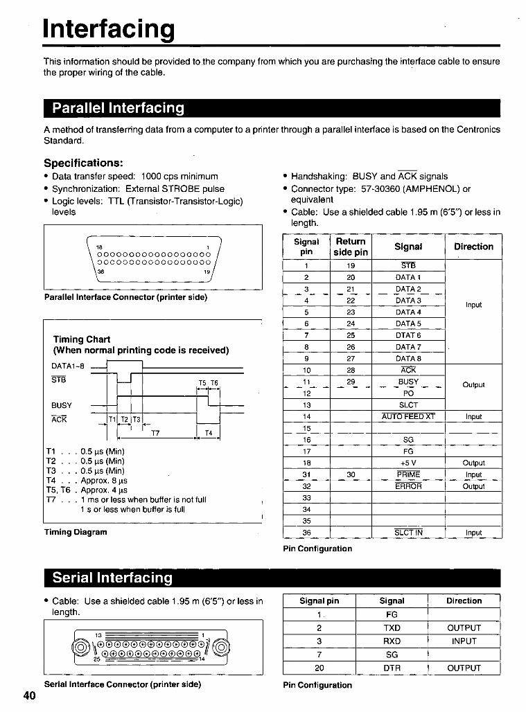
Interfacing This information should be provided to the company from which you are purchasing the interface cable to ensure the proper wiring of the cable. .
Parallel Interfacing A method of transferring data from a computer to a printer through a parallel interface is based on the Centronics Standard.
Specifications: • Data transfer speed: 1000 cps minimum
• Synchronization: External STROBE pulse
• Logic levels: TTL (Transistor-Transistor-Logic) levels
~8 '!/ 000000000000000000 000000000000000000 ~ 19
Parallel Interface Connector (printer side)
Timing Chart (When normal printing code is received)
DATAl-8
STB
BUSY
ACK
-
-l
'--
T1 T2 -,
T1 . 0.5 ~s (Min) T2 . 0.5 ~s (Min) T3 . 0.5 ~s (Min) T 4 . Approx. 8 ~s T5, T6 . Approx. 4 ~s
T5 T6 ~-t-
I
T3 -r-T7 T4
T7 . . . 1 ms or less when buffer is not full 1 s or less when buffer is full
Timing Diagram
Serial Interfacing
r--
• Cable: Use a shielded cable 1.95 m (6'5") or less in length.
Serial Interface Connector (printer side)
• Handshaking: BUSY and ACK signals
• Connector type: 57-30360 (AMPHENOL) or equivalent
• Cable: Use a shielded cable 1.95 m (6'5") or less in length.
Signal Return Signal Direction pin side pin
1 19 STB 2 20 DATA 1 3 21 DATA 2 4 22 DATA 3 Input 5 23 DATA 4 6 24 DATA 5 7 25 OTAT6 8 26 DATA 7 9 27 DATA 8 10 28 ACK 11 29 BUSY Output 12 PO 13 SLCT 14 AUTO FEEDXT Input
15 16 SG 17 FG 18 +5V Output 31 30 PRIME Input
32 ERROR Output
33 34 35 36 SLCTIN Input
Pin Configuration
Signal pin Signal Direction
1 FG 2 TXD OUTPUT
3 RXO INPUT
7 SG 20 OTR OUTPUT
Pin Configuration
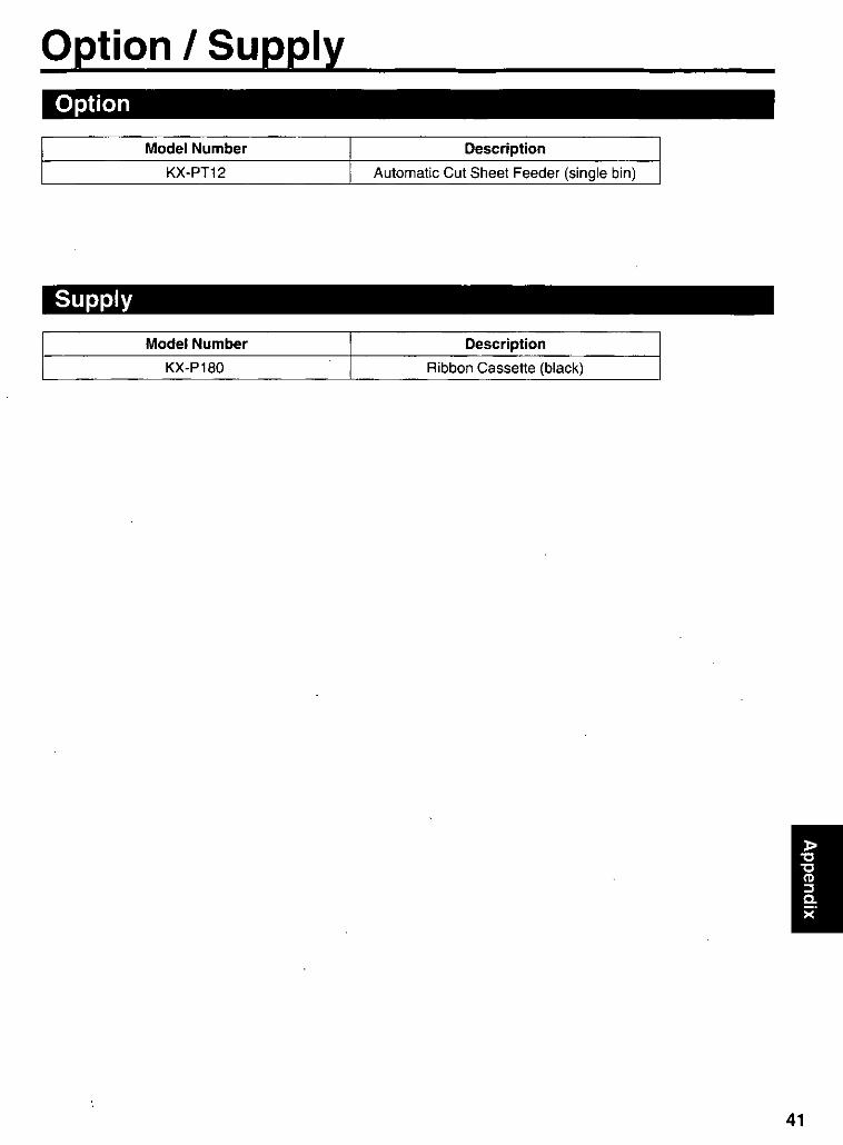
Option I Supply Option
Model Number Description
KX-PT12 Automatic Cut Sheet Feeder (single bin)
Supply
Model Number Description
KX-P180 Ribbon Cassette (black)
41

42
Index
Automatic Carriage Return (AUTO CR) . Automatic Line Feed (AUTO LF) ....
· .. 24 . 24,33
Buffer . . . . . . . . . . . . . . . . . . . 24, 33, 37
Cable ............ . Caution ........... . Centering (CTR PRINTHEAD) Character set . . . . . . . . . Code page .......... . Command Reference program Connecting ......... . Control Panel Software program Control Panel switches . Cut Sheet Feeder (CSF) ....
Data length .. . Detectors ... . Dot configuration
Emulation .......... . End-User License Agreement .
Factory setting. Fanfold paper . Font ..... . Form feed (FF)
Head service life . High Speed mode
. 11 6, 7 . 24
.24,27,33 · .. 24,33 · 18,19,27 · . . . . 11 · .... 24 · 10,28,33 .24,33,41
.24,34
.31,37 · .. 37
. 24,33 · .. 4
. 26,32,34 · 13,38,39 · 24,28,33 · .... 29
. 37
.29
Initial Setup mode .. · .......... 32 Interface ...... . Interface Setup mode Italics ....... .
· 10, 11, 24, 34, 37, 40 . 34
· .......... 24
Line feed (LF) . . . . . . . . . . . . . . ..... 29
Maintenance. . Margin ..... Micro line feed.
.35
.24
.30
Operating environment Option ........ .
Page format . . . . . Page length . . . . . Paper installation . . Paper specifications . Paper thickness .. Parallel interface . Parts of the printer Pitch ..... Power switch Printer driver Printing area Printing direction
Graphic direction Text direction ..
Printing speed . . . Proportional Spacing (PS)
Reverse micro line feed . Ribbon cassette . . . . .
Serial interface Setup Disk . Specifications Supply ....
Tear Off ....... . Top of Form (TOF) set Troubleshooting ....
. 37
. 41
· .. 24 · 24,33 · 13, 15 · .. 38 · .. 38
10,11,34,40 · ... 10
· . 24,28,33 · ... 10, 12 18,19,20,22
. . 39 · .. 37 · 24,33 · .. 24 · .. 37 · 27,33
· ... 30 8,12,41
. ..... 10, 11, 34, 40 8,17,18,19,20,22,27
37,38 . . . . . . . . . . . . 41
16,24,33 · 24,30
· ... 35
Unpacking . . . . . . . . . . . . . . . . . . . .. 8
Warning ....... . · ..... 6 Windows printer driver 18,19,20,22
Zero font. . . . . . . . . . . . . . . . . . . . 24, 33

43

Printed in Japan
Panasonic Computer Peripheral Company Division of Panasonic Communications & Systems Company A Unit of Matsushita Electric Corporation of America Two Panasonic Way, Secaucus, New Jersey 07094
Panasonic Sales Company Division of Matsushita Electric of Puerto Rico, Inc. San Gabriel Industrial Park, 65th Infantry Avenue KM. 9.5 Carolina, Puerto Rico 00985
Matsushita Electric Industrial CO.,Ltd. Central P.O. Box 288, Osaka 530-91, Japan
PJQMA0408ZA 5119850 []ill