kyle form 5/triple-single installation and operation
TRANSCRIPT
Printed in USA
Safety Information . . . . . . . . . . . . . . . . . . . . . . . . . 2Product Information . . . . . . . . . . . . . . . . . . . . . . . . 3
Introduction . . . . . . . . . . . . . . . . . . . . . . . . . . . . . . . 3ANSI Standards . . . . . . . . . . . . . . . . . . . . . . . . . . . 3Quality Standards . . . . . . . . . . . . . . . . . . . . . . . . . . 3Acceptance and Initial Inspection . . . . . . . . . . . . . . 3Handling and Storage . . . . . . . . . . . . . . . . . . . . . . . 3Battery Replacement . . . . . . . . . . . . . . . . . . . . . . . 3Battery Disposal . . . . . . . . . . . . . . . . . . . . . . . . . . . 3Control Power . . . . . . . . . . . . . . . . . . . . . . . . . . . . . 3Initializing the Control . . . . . . . . . . . . . . . . . . . . . . . 4
Form 5/Triple-Single Control Description . . . . . . 5Phase Operation . . . . . . . . . . . . . . . . . . . . . . . . . . . 5Ground Operation . . . . . . . . . . . . . . . . . . . . . . . . . . 5Sensitive Ground/Earth Fault Operation . . . . . . . . . 6Recloser Interface (RIF) Module . . . . . . . . . . . . . . 6Central Processing Unit (CPU) Module . . . . . . . . . 6Discrete Interface (DIF) Module . . . . . . . . . . . . . . . 6Power Supply Module . . . . . . . . . . . . . . . . . . . . . . . 6Triple-Single Control Operator Panel . . . . . . . . . . . 7Manual Control Operation . . . . . . . . . . . . . . . . . . . 15Control Features . . . . . . . . . . . . . . . . . . . . . . . . . . . 15Communications . . . . . . . . . . . . . . . . . . . . . . . . . . . 20
Auxiliary Power for Accessories . . . . . . . . . . . . . . 21Recloser Interface (RIF) Module Configuration . . 21
Form 5/Triple-Single Universal Device Protection(UDP) Control . . . . . . . . . . . . . . . . . . . . . . . . . . . . . 22Discrete Interface (DIF) Accessory . . . . . . . . . . . . 23
Customer Connection Information . . . . . . . . . . . . . 23Standard and UDP DIF Module 1 Inputs . . . . . . . . 26Standard and UDP DIF Module 1 Outputs . . . . . . . 27Standard and UDP Module 2 Inputs . . . . . . . . . . . . 28Standard and UDP Module 2 Outputs . . . . . . . . . . 29
Input Accuracy . . . . . . . . . . . . . . . . . . . . . . . . . . . . 30Installation Procedure . . . . . . . . . . . . . . . . . . . . . . 31
Initial Programming Prior to Installation . . . . . . . . . 31Control Cable . . . . . . . . . . . . . . . . . . . . . . . . . . . . . 31Triple-Single Control Junction Box . . . . . . . . . . . . . 31Mounting the Control . . . . . . . . . . . . . . . . . . . . . . . 32Grounding the Control . . . . . . . . . . . . . . . . . . . . . . 33Customer Connections for AC Power . . . . . . . . . . . 37Customer Connections for Metering . . . . . . . . . . . . 37Before Placing Control and Recloser Into Service . 41
Testing . . . . . . . . . . . . . . . . . . . . . . . . . . . . . . . . . . . 41Testing an Installed Control . . . . . . . . . . . . . . . . . . 41Electrical Testing of NOVA-TS Reclosers . . . . . . . 42Remove the Control from Service . . . . . . . . . . . . . 42Battery Test Procedure . . . . . . . . . . . . . . . . . . . . . . 43Return the Control to Service . . . . . . . . . . . . . . . . . 44
Additional Information . . . . . . . . . . . . . . . . . . . . . . 44
1
Service Information
ReclosersKyle® Form 5/Triple-SingleMicroprocessor-Based Recloser ControlInstallation and Operation Instructions S280-42-3
March 2003 • Supersedes 7/01
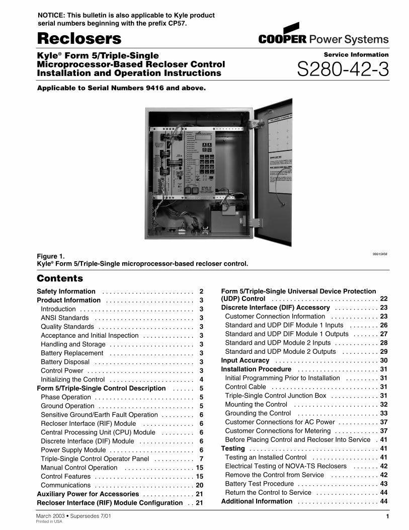
Figure 1.Kyle® Form 5/Triple-Single microprocessor-based recloser control.
99015KM
Contents
Applicable to Serial Numbers 9416 and above.
NOTICE: This bulletin is also applicable to Kyle productserial numbers beginning with the prefix CP57.
Kyle Form 5/Triple-Single Microprocessor-Based Recloser Control Installation and Operation Instructions
2
The instructions in this manual are not intended as a sub-stitute for proper training or adequate experience in thesafe operation of the equipment described. Only compe-tent technicians who are familiar with this equipmentshould install, operate, and service it.
A competent technician has these qualifications:
• Is thoroughly familiar with these instructions.
• Is trained in industry-accepted high- and low-voltagesafe operating practices and procedures.
• Is trained and authorized to energize, de-energize,clear, and ground power distribution equipment.
• Is trained in the care and use of protective equipmentsuch as flash clothing, safety glasses, face shield,hard hat, rubber gloves, hotstick, etc.
Following is important safety information. For safe instal-lation and operation of this equipment, be sure to readand understand all cautions and warnings.
Safety InstructionsFollowing are general caution and warning statementsthat apply to this equipment. Additional statements,related to specific tasks and procedures, are locatedthroughout the manual.
SAFETY INFORMATION
WARNING: This equipment is not intended toprotect human life. Follow all locally approved
procedures and safety practices when installing oroperating this equipment. Failure to comply can resultin death, severe personal injury, and equipment dam-age. G102.1
!
DANGER: Hazardous voltage. Contact withhazardous voltage will cause death or severe per-
sonal injury. Follow all locally approved safety proce-dures when working around high- and low-voltage linesand equipment. G103.3
!
WARNING: Before installing, operating, main-taining, or testing this equipment, carefully read
and understand the contents of this manual. Improperoperation, handling or maintenance can result in death,severe personal injury, and equipment damage. G101.0
!
WARNING: Power distribution equipment mustbe properly selected for the intended application.
It must be installed and serviced by competent person-nel who have been trained and understand propersafety procedures. These instructions are written forsuch personnel and are not a substitute for adequatetraining and experience in safety procedures. Failure toproperly select, install, or maintain power distributionequipment can result in death, severe personal injury,and equipment damage. G122.2
!
SAFETY FOR LIFECooper Power Systems products meet or exceed all applicable industry standards relating to product safety. We activelypromote safe practices in the use and maintenance of our products through our service literature, instructional trainingprograms, and the continuous efforts of all Cooper Power Systems employees involved in product design, manufacture,marketing, and service.
We strongly urge that you always follow all locally approved safety procedures and safety instructions when workingaround high voltage lines and equipment and support our “Safety For Life” mission.
!SAFETYFOR LIFE
!SAFETYFOR LIFE
This manual may contain four types of hazardstatements:
DANGER: Indicates an imminently haz-ardous situation which, if not avoided, will
result in death or serious injury.
WARNING: Indicates a potentially hazardoussituation which, if not avoided, could result in
death or serious injury.
CAUTION: Indicates a potentially hazardoussituation which, if not avoided, may result in
minor or moderate injury.
CAUTION: Indicates a potentially hazardous situ-ation which, if not avoided, may result in equip-ment damage only.
!
!
Hazard Statement Definitions
!
IntroductionService Information S280-42-3 provides installation andoperation instructions for the Kyle® Form 5/Triple-Singlemicroprocessor-based electronic recloser controls. Thiscontrol is used exclusively with Kyle® Type NOVA-TSreclosers. Refer to Service Information S280-42-2 TypeNOVA-TS Electronically-Controlled Recloser Installationand Operation Instructions for additional information.
Read This Manual FirstRead and understand the contents of this manual and fol-low all locally approved procedures and safety practicesbefore installing or operating this equipment.
Additional InformationThese instructions cannot cover all details or variations inthe equipment, procedures, or process described, norprovide directions for meeting every possible contingencyduring installation, operation, or maintenance. When addi-tional information is desired to satisfy a problem not cov-ered sufficiently for the user's purpose, contact yourCooper Power Systems sales representative.
ANSI StandardsKyle reclosers are designed and tested in accordancewith the following ANSI standards: C37.60 and C37.85and ANSI Guide C37.61.
Quality StandardsISO 9001:2000 Certified Quality Management System
Acceptance andInitial InspectionEach Form 5/Triple-Single control is completely assem-bled, tested, and inspected at the factory. It is carefullycalibrated, adjusted, and in good condition whenaccepted by the carrier for shipment.
Upon receipt, inspect the carton for signs of damage.Unpack the control and inspect it thoroughly for damageincurred during shipment. If damage is discovered, file aclaim with the carrier immediately.
Handling and StorageBe careful during handling and storage of the control tominimize the possibility of damage. If the control is to bestored for any length of time prior to installation, providea clean, dry storage area. If storage is in a humid atmo-sphere, make provisions to keep the control circuitryenergized.
Note: To energize the control, apply AC power to the AC sup-ply input connector block TB1 located left of theRecloser Interface (RIF) module within the control.Refer to the Customer Connection for AC power sec-tion in this manual.
Control Battery Storage and ChargingTwo 12 Vdc, 13- Amp-hour control batteries in the Form5/Triple-Single control are fully charged prior to shipmentand is ready for use.
Note: When shipped from the factory, the battery source is dis-connected and its output plugs are taped to the cabinet.Connect the battery plugs into the mating connectors tocomplete the battery circuit.
Temperature has an effect on battery life. Sealed leadacid batteries should be stored, fully-charged, at roomtemperature. Never store lead acid batteries at tempera-ture exceeding 47°C (117°F), as damage can result inapproximately one month.
To keep the batteries charged, energize the control’sbuilt-in charger with AC power applied to the user AC sup-ply input connector block TB1, located left of the RIF mod-ule within the control cabinet.
Battery ReplacementIn a typical application, the life expectancy of a lead acidbattery is three to five years. To determine the state of thebattery, perform a bench battery test. Battery replacementis recommended after four years for lead acid batteries orif the battery fails the bench battery test procedure. TheForm 5/Triple-Single control batteries have different dimen-sions; therefore, if the replacement battery ordered is a dif-ferent brand than the original battery, a kit with mountinghardware may be required.
Battery DisposalDispose expired batteries in an environmentally responsi-ble manner. Consult local regulations for proper batterydisposal.
S280-42-3
3
!SAFETYFOR LIFE
PRODUCT INFORMATION
IMPORTANT: Connect the control battery when ACpower is connected to the control’s AC supply InputTerminal Block. The battery must be disconnectedprior to shipping or storing the control.
IMPORTANT: To maintain sufficient charge to oper-ate the control and prevent battery cell damage, thesealed lead-acid batteries should be charged after nomore than three months of storage.
Control PowerThe primary source of power is factory configured for 120Vac or 240 Vac. Primary power is rectified to charge thepower capacitor and to power the dc/dc converter thatprovides power to the control. A minimum of 500 mA of accurrent is required for heater operation, battery chargingcurrent, and to keep all modules energized. The Kyle®
Form 5/Triple-Single recloser control is equipped with twodc-to-dc converters, an interface circuit, and a fullyshielded 26-pin cable.
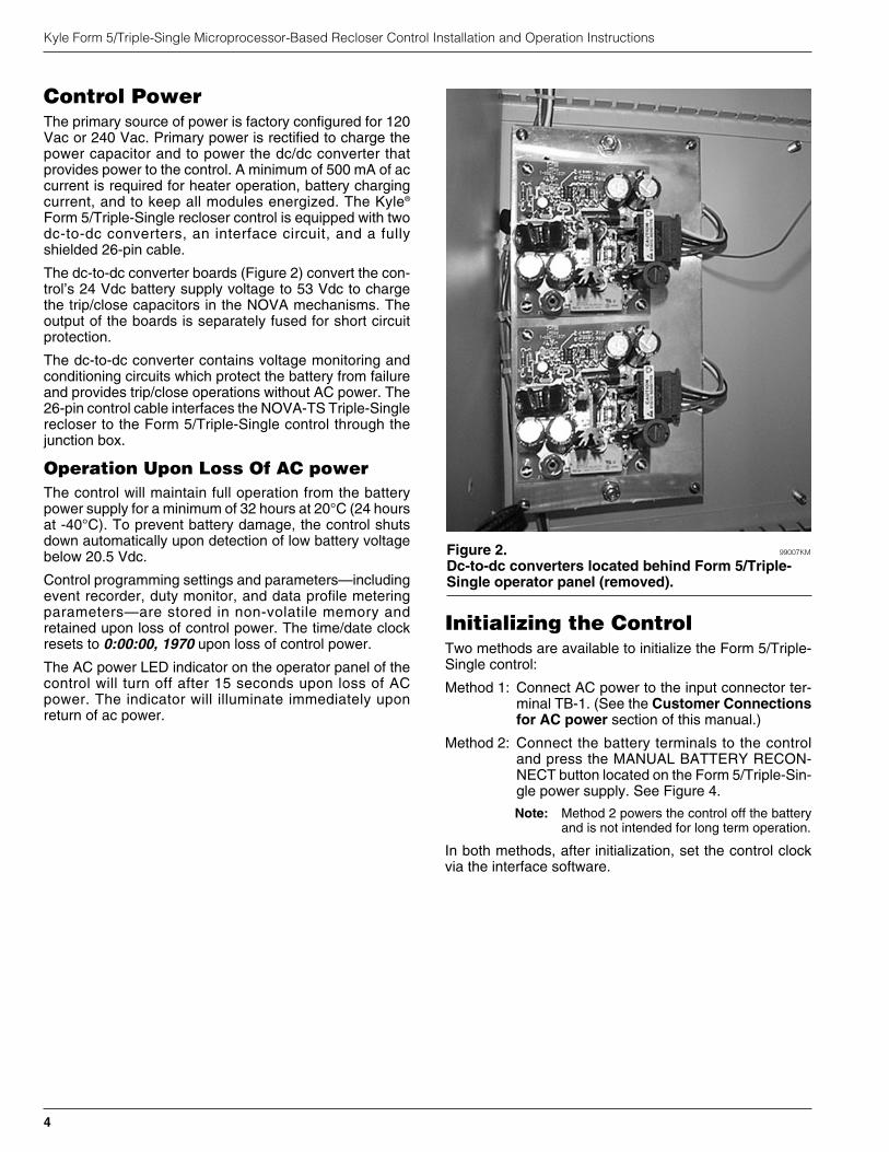
The dc-to-dc converter boards (Figure 2) convert the con-trol’s 24 Vdc battery supply voltage to 53 Vdc to chargethe trip/close capacitors in the NOVA mechanisms. Theoutput of the boards is separately fused for short circuitprotection.
The dc-to-dc converter contains voltage monitoring andconditioning circuits which protect the battery from failureand provides trip/close operations without AC power. The26-pin control cable interfaces the NOVA-TS Triple-Singlerecloser to the Form 5/Triple-Single control through thejunction box.
Operation Upon Loss Of AC powerThe control will maintain full operation from the batterypower supply for a minimum of 32 hours at 20°C (24 hoursat -40°C). To prevent battery damage, the control shutsdown automatically upon detection of low battery voltagebelow 20.5 Vdc.
Control programming settings and parameters—includingevent recorder, duty monitor, and data profile meteringparameters—are stored in non-volatile memory andretained upon loss of control power. The time/date clockresets to 0:00:00, 1970 upon loss of control power.
The AC power LED indicator on the operator panel of thecontrol will turn off after 15 seconds upon loss of ACpower. The indicator will illuminate immediately uponreturn of ac power.
Initializing the ControlTwo methods are available to initialize the Form 5/Triple-Single control:
Method 1: Connect AC power to the input connector ter-minal TB-1. (See the Customer Connectionsfor AC power section of this manual.)
Method 2: Connect the battery terminals to the controland press the MANUAL BATTERY RECON-NECT button located on the Form 5/Triple-Sin-gle power supply. See Figure 4.
Note: Method 2 powers the control off the batteryand is not intended for long term operation.
In both methods, after initialization, set the control clockvia the interface software.
Kyle Form 5/Triple-Single Microprocessor-Based Recloser Control Installation and Operation Instructions
4
Figure 2. 99007KM
Dc-to-dc converters located behind Form 5/Triple-Single operator panel (removed).
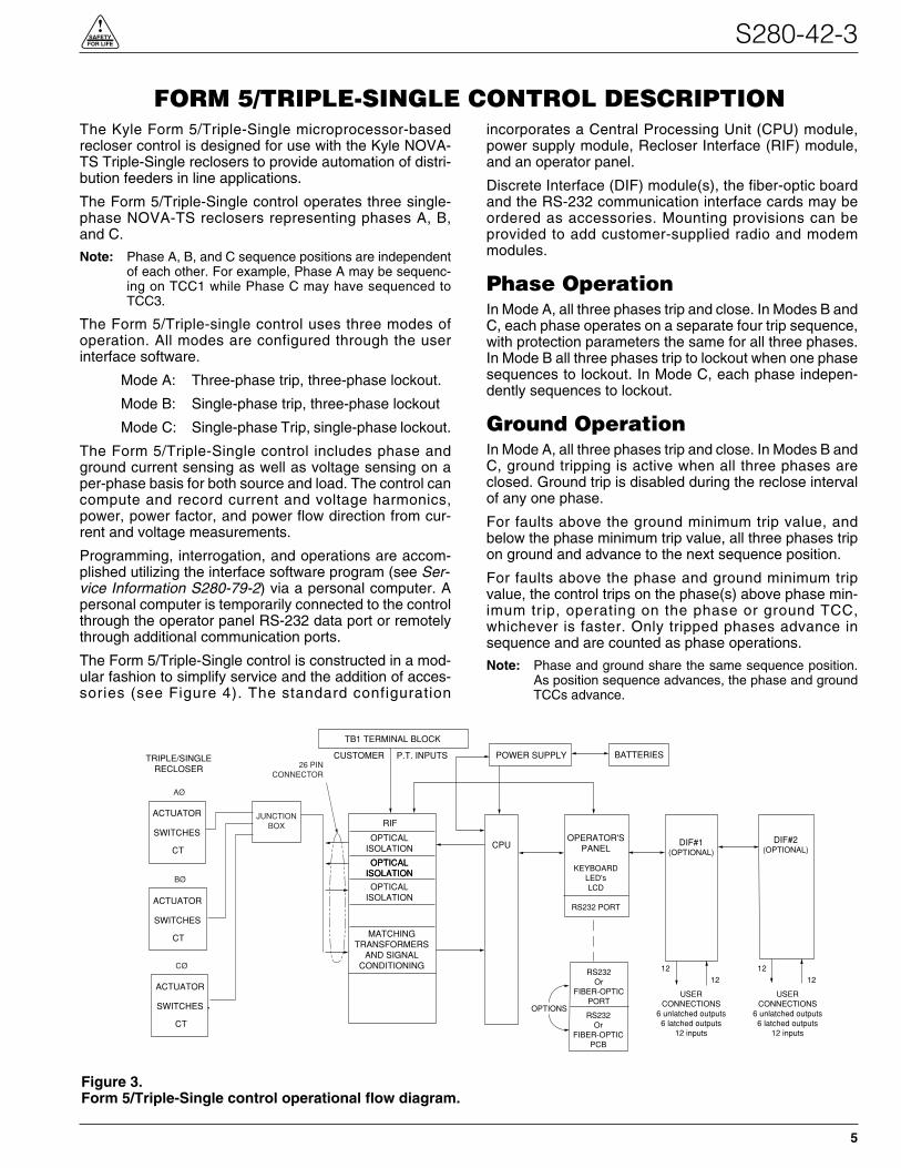
The Kyle Form 5/Triple-Single microprocessor-basedrecloser control is designed for use with the Kyle NOVA-TS Triple-Single reclosers to provide automation of distri-bution feeders in line applications.
The Form 5/Triple-Single control operates three single-phase NOVA-TS reclosers representing phases A, B,and C.
Note: Phase A, B, and C sequence positions are independentof each other. For example, Phase A may be sequenc-ing on TCC1 while Phase C may have sequenced toTCC3.
The Form 5/Triple-single control uses three modes ofoperation. All modes are configured through the userinterface software.
Mode A: Three-phase trip, three-phase lockout.
Mode B: Single-phase trip, three-phase lockout
Mode C: Single-phase Trip, single-phase lockout.
The Form 5/Triple-Single control includes phase andground current sensing as well as voltage sensing on aper-phase basis for both source and load. The control cancompute and record current and voltage harmonics,power, power factor, and power flow direction from cur-rent and voltage measurements.
Programming, interrogation, and operations are accom-plished utilizing the interface software program (see Ser-vice Information S280-79-2) via a personal computer. Apersonal computer is temporarily connected to the controlthrough the operator panel RS-232 data port or remotelythrough additional communication ports.
The Form 5/Triple-Single control is constructed in a mod-ular fashion to simplify service and the addition of acces-sories (see Figure 4). The standard configuration
incorporates a Central Processing Unit (CPU) module,power supply module, Recloser Interface (RIF) module,and an operator panel.
Discrete Interface (DIF) module(s), the fiber-optic boardand the RS-232 communication interface cards may beordered as accessories. Mounting provisions can beprovided to add customer-supplied radio and modemmodules.
Phase OperationIn Mode A, all three phases trip and close. In Modes B andC, each phase operates on a separate four trip sequence,with protection parameters the same for all three phases.In Mode B all three phases trip to lockout when one phasesequences to lockout. In Mode C, each phase indepen-dently sequences to lockout.
Ground OperationIn Mode A, all three phases trip and close. In Modes B andC, ground tripping is active when all three phases areclosed. Ground trip is disabled during the reclose intervalof any one phase.
For faults above the ground minimum trip value, andbelow the phase minimum trip value, all three phases tripon ground and advance to the next sequence position.
For faults above the phase and ground minimum tripvalue, the control trips on the phase(s) above phase min-imum trip, operating on the phase or ground TCC,whichever is faster. Only tripped phases advance insequence and are counted as phase operations.
Note: Phase and ground share the same sequence position.As position sequence advances, the phase and groundTCCs advance.
S280-42-3
5
!SAFETYFOR LIFE
Figure 3.Form 5/Triple-Single control operational flow diagram.
FORM 5/TRIPLE-SINGLE CONTROL DESCRIPTION
BATTERIES
ACTUATOR
CT
SWITCHES
TRIPLE/SINGLERECLOSER
RIF
OPTICALISOLATION
OPTICALISOLATIONOPTICAL
ISOLATION
OPTICALISOLATION
MATCHINGTRANSFORMERS
AND SIGNALCONDITIONING
TB1 TERMINAL BLOCK
CUSTOMER P.T. INPUTS POWER SUPPLY
CPU
RS232Or
FIBER-OPTICPORT
RS232Or
FIBER-OPTICPCB
OPTIONS
OPERATOR'SPANEL
KEYBOARDLED'sLCD
RS232 PORT
DIF#1(OPTIONAL)
DIF#2(OPTIONAL)
USERCONNECTIONS
6 unlatched outputs6 latched outputs
12 inputs
1212
USERCONNECTIONS
6 unlatched outputs6 latched outputs
12 inputs
1212
AØ
BØ
CØ
JUNCTIONBOX
26 PINCONNECTOR
ACTUATOR
CT
SWITCHES
ACTUATOR
CT
SWITCHES

Sensitive Ground/Earth FaultOperationSensitive Ground/Earth Fault (SGF/SEF) is active whenall three phases are closed. For SGF faults, all threephases trip at one time.
Recloser Interface (RIF) ModuleThe Recloser Interface (RIF) Module provides the inter-face between the recloser and the CPU module, as wellas the interface between the voltage sensors and theCPU module. The RIF module provides three currenttransformer inputs, three open and close circuits andthree sets of OPEN, CLOSE, and yellow operating handleLOCKOUT status inputs (one for each phase). These sig-nals always indicate the true state of each Form 5/Triple-Single recloser, regardless of the position of the yellowoperating handle.
One connector on the bottom of the control cabinet pro-vides the connection for all three phases of the Kyle TypeNOVA-TS recloser.
The RIF board accepts either 12, 120, or 240 Vac voltageinputs for metering. The factory configuration is outlinedon the module label and can be customized to user spec-ification. See RECLOSER INTERFACE (RIF) MODULECONFIGURATION section of this manual.
Central Processing Unit (CPU)ModuleThe CPU module is the center of the Form 5/Triple-Singlecontrol. The CPU contains a 32-bit micro-controller, a Dig-ital Signal Processor, RAM and EEPROM memory, and a
16-bit analog-to-digital converter. The CPU moduleaccepts 16 analog inputs which it routes through the digi-tal signal processor, which samples 32 times per cycle, tocompute harmonic analysis to the 15th harmonic.
Discrete Interface (DIF) ModuleThe Discrete Interface (DIF) module allows users withexisting RTUs the ability to interface with the Form5/Triple-Single control. The DIF module contains 12inputs and 12 outputs for remote or supervisory functions.Each Form 5/Triple-Single control can accommodate twoDIF modules. See DISCRETE INTERFACE (DIF)ACCESSORY section of this manual.
Power Supply ModuleThe Power Supply module is designed to accept 100 to134 Vac or 200 to 268 Vac user-supplied input power ateither 50 or 60 Hz.
The Power supply module (connection P9) providespower to the auxiliary communication equipment such astransceivers and modems. Auxiliary output provides 24Vdc (12 Vdc is available) for user loads. The auxiliarypower supply has the capability to provide a load of up to40 W peak (1 second) and 3 W average. The auxiliarypower is fused and current-limited to prevent user loadsfrom disabling the control.
If ac power is lost, the control batteries power the controluntil the battery voltage drops below 20.5 V at which pointthe power supply disconnects the battery from the load.
Kyle Form 5/Triple-Single Microprocessor-Based Recloser Control Installation and Operation Instructions
6
Figure 4.Form 5/Triple-Single UDP control operating panel with interface modules and radio mounting provisions.
99015KM
Control Cable Receptacleand Control Grounding Lug
(located beneath cabinet) Control Batteries
Computer Processor(CPU) Module
Recloser Interface(RIF) Module
TB1 ConnectorBlock
PowerSupplyModule
DC-to-DC Converters
(located behind operatorpanel)
Grounding Strap
Manual BatteryReconnect Button
Auxiliary PowerConnection (P9)
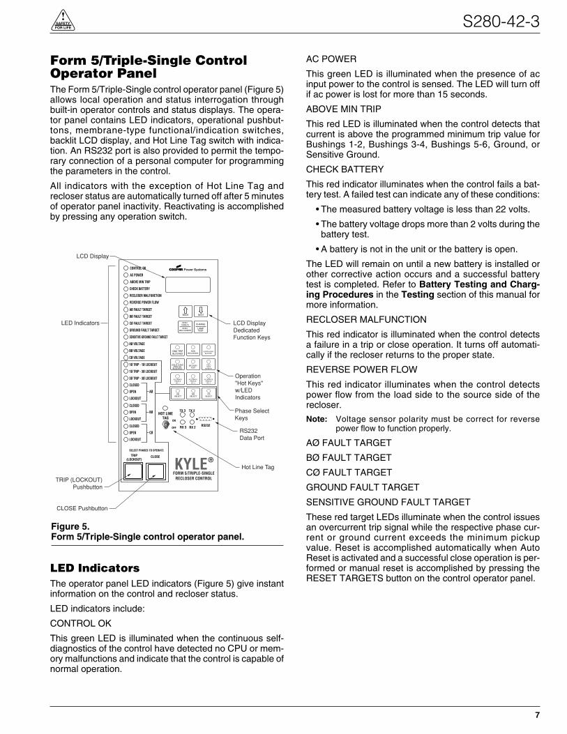
Form 5/Triple-Single ControlOperator PanelThe Form 5/Triple-Single control operator panel (Figure 5)allows local operation and status interrogation throughbuilt-in operator controls and status displays. The opera-tor panel contains LED indicators, operational pushbut-tons, membrane-type functional/indication switches,backlit LCD display, and Hot Line Tag switch with indica-tion. An RS232 port is also provided to permit the tempo-rary connection of a personal computer for programmingthe parameters in the control.
All indicators with the exception of Hot Line Tag andrecloser status are automatically turned off after 5 minutesof operator panel inactivity. Reactivating is accomplishedby pressing any operation switch.
LED IndicatorsThe operator panel LED indicators (Figure 5) give instantinformation on the control and recloser status.
LED indicators include:
CONTROL OK
This green LED is illuminated when the continuous self-diagnostics of the control have detected no CPU or mem-ory malfunctions and indicate that the control is capable ofnormal operation.
AC POWER
This green LED is illuminated when the presence of acinput power to the control is sensed. The LED will turn offif ac power is lost for more than 15 seconds.
ABOVE MIN TRIP
This red LED is illuminated when the control detects thatcurrent is above the programmed minimum trip value forBushings 1-2, Bushings 3-4, Bushings 5-6, Ground, orSensitive Ground.
CHECK BATTERY
This red indicator illuminates when the control fails a bat-tery test. A failed test can indicate any of these conditions:
• The measured battery voltage is less than 22 volts.
• The battery voltage drops more than 2 volts during thebattery test.
• A battery is not in the unit or the battery is open.
The LED will remain on until a new battery is installed orother corrective action occurs and a successful batterytest is completed. Refer to Battery Testing and Charg-ing Procedures in the Testing section of this manual formore information.
RECLOSER MALFUNCTION
This red indicator is illuminated when the control detectsa failure in a trip or close operation. It turns off automati-cally if the recloser returns to the proper state.
REVERSE POWER FLOW
This red indicator illuminates when the control detectspower flow from the load side to the source side of therecloser.
Note: Voltage sensor polarity must be correct for reversepower flow to function properly.
AØ FAULT TARGET
BØ FAULT TARGET
CØ FAULT TARGET
GROUND FAULT TARGET
SENSITIVE GROUND FAULT TARGET
These red target LEDs illuminate when the control issuesan overcurrent trip signal while the respective phase cur-rent or ground current exceeds the minimum pickupvalue. Reset is accomplished automatically when AutoReset is activated and a successful close operation is per-formed or manual reset is accomplished by pressing theRESET TARGETS button on the control operator panel.
S280-42-3
7
!SAFETYFOR LIFE
Figure 5.Form 5/Triple-Single control operator panel.
CONTROL OK
AC POWER
ABOVE MIN TRIP
REVERSE POWER FLOW
RECLOSER MALFUNCTION
CHECK BATTERY
AØ FAULT TARGET
BØ FAULT TARGET
CØ FAULT TARGET
GROUND FAULT TARGET
SENSITIVE-GROUND FAULT TARGET
AØ VOLTAGE
BØ VOLTAGE
CØ VOLTAGE
1Ø TRIP - 1Ø LOCKOUT
1Ø TRIP - 3Ø LOCKOUT
3Ø TRIP - 3Ø LOCKOUT
CLOSETRIP(LOCKOUT) KYLE®
FORM 5/TRIPLE-SINGLERECLOSER CONTROL
TX 2
RX 2
TX 3
RX 3
BACK NEXT
LAMPTEST
CHANGERESET
TARGETS
RESETMAX CURRENT
GND TRIPBLOCKED
NONRECLOSING
SUPERVISORYBLOCKED
COLD LOADPICK UP
BLOCKED
BATTERYTEST
FASTTRIPS
DISABLED
ALTERNATEPROFILE
NO. 1
ALTERNATEPROFILE
NO. 2
ALTERNATEPROFILE
NO. 3
AØSELECT
BØSELECT
CØSELECT
CLOSED
OPEN
LOCKOUT
AØ
CLOSED
OPEN
LOCKOUT
BØ
CLOSED
OPEN
LOCKOUT
CØ
SELECT PHASES TO OPERATE
RS232
HOT LINETAG
ON
OFF
LED Indicators
LCD Display
TRIP (LOCKOUT)Pushbutton
CLOSE Pushbutton
LCD DisplayDedicatedFunction Keys
Operation"Hot Keys"w/LEDIndicators
RS232Data Port
Hot Line Tag
Phase SelectKeys
AØ VOLTAGE
BØ VOLTAGE
CØ VOLTAGE
These red voltage LEDs illuminate when the controldetects the presence of voltage on the respective bush-ings as connected to TB1. Refer to the Customer Con-nections for AC Power section in these instructions todetermine the appropriate power connections.
1Ø TRIP - 1Ø LOCKOUT
1Ø TRIP - 3Ø LOCKOUT
3Ø TRIP - 3Ø LOCKOUT
Indicates the Triple -Single mode of operation (Modes C,B, A).
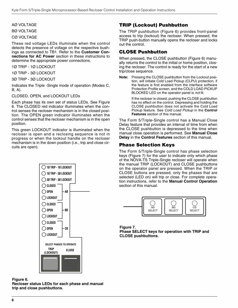
CLOSED, OPEN, and LOCKOUT LEDs
Each phase has its own set of status LEDs. See Figure6. The CLOSED red indicator illuminates when the con-trol senses the recloser mechanism is in the closed posi-tion. The OPEN green indicator illuminates when thecontrol senses that the recloser mechanism is in the openposition.
This green LOCKOUT indicator is illuminated when therecloser is open and a reclosing sequence is not inprogress or when the lockout handle on the reclosermechanism is in the down position (i.e., trip and close cir-cuits are open).
TRIP (Lockout) PushbuttonThe TRIP pushbutton (Figure 6) provides front-panelaccess to trip (lockout) the recloser. When pressed, theTRIP push-button manually opens the recloser and locksout the control.
CLOSE PushbuttonWhen pressed, the CLOSE pushbutton (Figure 6) manu-ally returns the control to the initial or home position, clos-ing the recloser. The control is ready for the start of a newtrip/close sequence.
Note: Pressing the CLOSE pushbutton from the Lockout posi-tion, will initiate Cold Load Pickup (CLPU) protection, ifthe feature is first enabled from the interface softwareProtection Profile screen, and the COLD LOAD PICKUPBLOCKED LED on the operator panel is not lit.
If the recloser is closed, pushing the CLOSE pushbuttonhas no effect on the control. Depressing and holding theCLOSE pushbutton does not activate the Cold LoadPickup feature. See Cold Load Pickup in the ControlFeatures section of this manual.
The Form 5/Triple-Single control has a Manual CloseDelay feature that provides an interval of time from whenthe CLOSE pushbutton is depressed to the time whenmanual close operation is performed. See Manual CloseDelay in the Control Features section of this manual.
Phase Selection KeysThe Form 5/Triple-Single control has phase selectionkeys (Figure 7) for the user to indicate only which phaseof the NOVA-TS Triple-Single recloser will operate whenthe manual TRIP (LOCKOUT) and CLOSE pushbuttonson the operator panel are pressed. When the TRIP orCLOSE buttons are pressed, only the phases that areselected (LED on) will trip or close. For complete opera-tion instructions, refer to the Manual Control Operationsection of this manual.
Kyle Form 5/Triple-Single Microprocessor-Based Recloser Control Installation and Operation Instructions
8
1Ø TRIP - 1Ø LOCKOUT
1Ø TRIP - 3Ø LOCKOUT
3Ø TRIP - 3Ø LOCKOUT
CLOSETRIP(LOCKOUT)
CLOSED
OPEN
LOCKOUT
AØ
CLOSED
OPEN
LOCKOUT
BØ
CLOSED
OPEN
LOCKOUT
CØ
SELECT PHASES TO OPERATE
Figure 6.Recloser status LEDs for each phase and manualtrip and close pushbuttons.
AØSELECT
BØSELECT
CØSELECT
Figure 7.Phase SELECT keys for operation with TRIP andCLOSE pushbuttons.
RS232 Communication PortThe standard Form 5/Triple-Single control is equippedwith an operator panel RS232 port for interface with a per-sonal computer running the Form 5/Triple-Single interfacesoftware program. This nine-pin female data communica-tion equipment (DCE) Port 1 permits the uploading of allprogramming information stored in the control, includingprotection profiles, event recorder, data profiles, alarms,counters, and metering information. Port 1 provides a sim-ple means to download operating parameters from a per-sonal computer to the control.The protocol, baud rate andaddress for Port 1 are identified from the LCD display.
If a fiber-optic or RS232 accessory board is connected toPort 2 (located on the back of the operator panel) anyexternal electrical connection from the operator panel willdisable the accessory board.
Note: The operator panel RS232 port is intended only for tem-porary connection of a personal computer. Permanentserial communications must be made via the RS232 orfiber-optic accessory board.
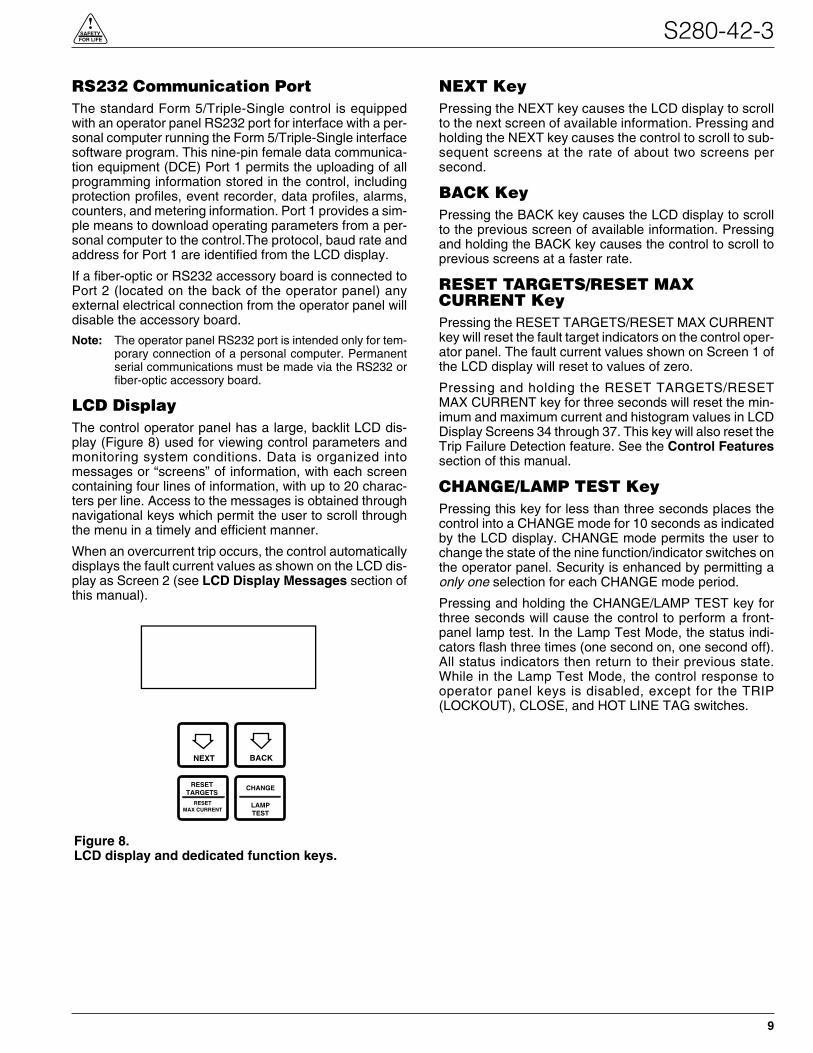
LCD DisplayThe control operator panel has a large, backlit LCD dis-play (Figure 8) used for viewing control parameters andmonitoring system conditions. Data is organized intomessages or “screens” of information, with each screencontaining four lines of information, with up to 20 charac-ters per line. Access to the messages is obtained throughnavigational keys which permit the user to scroll throughthe menu in a timely and efficient manner.
When an overcurrent trip occurs, the control automaticallydisplays the fault current values as shown on the LCD dis-play as Screen 2 (see LCD Display Messages section ofthis manual).
NEXT KeyPressing the NEXT key causes the LCD display to scrollto the next screen of available information. Pressing andholding the NEXT key causes the control to scroll to sub-sequent screens at the rate of about two screens persecond.
BACK KeyPressing the BACK key causes the LCD display to scrollto the previous screen of available information. Pressingand holding the BACK key causes the control to scroll toprevious screens at a faster rate.
RESET TARGETS/RESET MAXCURRENT KeyPressing the RESET TARGETS/RESET MAX CURRENTkey will reset the fault target indicators on the control oper-ator panel. The fault current values shown on Screen 1 ofthe LCD display will reset to values of zero.
Pressing and holding the RESET TARGETS/RESETMAX CURRENT key for three seconds will reset the min-imum and maximum current and histogram values in LCDDisplay Screens 34 through 37. This key will also reset theTrip Failure Detection feature. See the Control Featuressection of this manual.
CHANGE/LAMP TEST KeyPressing this key for less than three seconds places thecontrol into a CHANGE mode for 10 seconds as indicatedby the LCD display. CHANGE mode permits the user tochange the state of the nine function/indicator switches onthe operator panel. Security is enhanced by permitting aonly one selection for each CHANGE mode period.
Pressing and holding the CHANGE/LAMP TEST key forthree seconds will cause the control to perform a front-panel lamp test. In the Lamp Test Mode, the status indi-cators flash three times (one second on, one second off).All status indicators then return to their previous state.While in the Lamp Test Mode, the control response tooperator panel keys is disabled, except for the TRIP(LOCKOUT), CLOSE, and HOT LINE TAG switches.
S280-42-3
9
!SAFETYFOR LIFE
Figure 8.LCD display and dedicated function keys.
NEXT BACK
RESETTARGETS
CHANGE
LAMPTEST
RESETMAX CURRENT
Kyle Form 5/Triple-Single Microprocessor-Based Recloser Control Installation and Operation Instructions
10
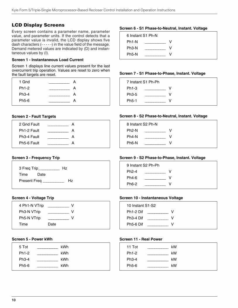
LCD Display ScreensEvery screen contains a parameter name, parametervalue, and parameter units. If the control detects that aparameter value is invalid, the LCD display shows fivedash characters (- - - - -) in the value field of the message.Demand metered values are indicated by (D) and instan-taneous values by (I).
1 Gnd ____________ A
Ph1-2 ____________ A
Ph3-4 ____________ A
Ph5-6 ____________ A
2 Gnd Fault ____________ A
Ph1-2 Fault ____________ A
Ph3-4 Fault ____________ A
Ph5-6 Fault ____________ A
3 Freq Trip____________ Hz
Time Date
Present Freq ____________ Hz
4 Ph1-N VTrip ____________ V
Ph3-N VTrip ____________ V
Ph5-N VTrip ____________ V
Time Date
5 Tot ____________ kWh
Ph1-2 ____________ kWh
Ph3-4 ____________ kWh
Ph5-6 ____________ kWh
6 Instant S1 Ph-N
Ph1-N ____________ V
Ph3-N ____________ V
Ph5-N ____________ V
7 Instant S1 Ph-Ph
Ph1-3 ____________ V
Ph3-5 ____________ V
Ph5-1 ____________ V
8 Instant S2 Ph-N
Ph2-N ____________ V
Ph4-N ____________ V
Ph6-N ____________ V
9 Instant S2 Ph-Ph
Ph2-4 ____________ V
Ph4-6 ____________ V
Ph6-2 ____________ V
Screen 1 - Instantaneous Load Current
Screen 1 displays line current values present for the lastovercurrent trip operation. Values are reset to zero whenthe fault targets are reset.
Screen 2 - Fault Targets
Screen 3 - Frequency Trip
Screen 4 - Voltage Trip
Screen 8 - S2 Phase-to-Neutral, Instant. Voltage
Screen 5 - Power kWh
Screen 6 - S1 Phase-to-Neutral, Instant. Voltage
Screen 9 - S2 Phase-to-Phase, Instant. Voltage
Screen 7 - S1 Phase-to-Phase, Instant. Voltage
11 Tot ____________ kW
Ph1-2 ____________ kW
Ph3-4 ____________ kW
Ph5-6 ____________ kW
Screen 11 - Real Power
10 Instant S1-S2
Ph1-2 Dif ____________ V
Ph3-4 Dif ____________ V
Ph5-6 Dif ____________ V
Screen 10 - Instantaneous Voltage
S280-42-3
11
!SAFETYFOR LIFE
14 Tot ____________ PF
Ph1-2 ____________ PF
Ph3-4 ____________ PF
Ph5-6 ____________ PF
15 Gnd ____________ %THDI
Ph1-2 ____________ %THDI
Ph3-4 ____________ %THDI
Ph5-6 ____________ %THDI
16 Instant S1 Ph-N
Ph1-N ____________ %THDV
Ph3-N ____________ %THDV
Ph5-N ____________ %THDV
17 Demand S1 Ph-N
Ph1-N(d) ____________ V
Ph3-N(d) ____________ V
Ph5-N(d) ____________ V
19 Demand S2 Ph-N
Ph2-N(d) ____________ V
Ph4-N(d) ____________ V
Ph6-N(d) ____________ V
20 Demand S2 Ph-Ph
Ph2-4(d) ____________ V
Ph4-6(d) ____________ V
Ph6-2(d) ____________ V
13 Tot ____________ kVAr
Ph1-2 ____________ kVAr
Ph3-4 ____________ kVAr
Ph5-6 ____________ kVAr
12 Tot ____________ kVA
Ph1-2 ____________ kVA
Ph3-4 ____________ kVA
Ph5-6 ____________ kVA
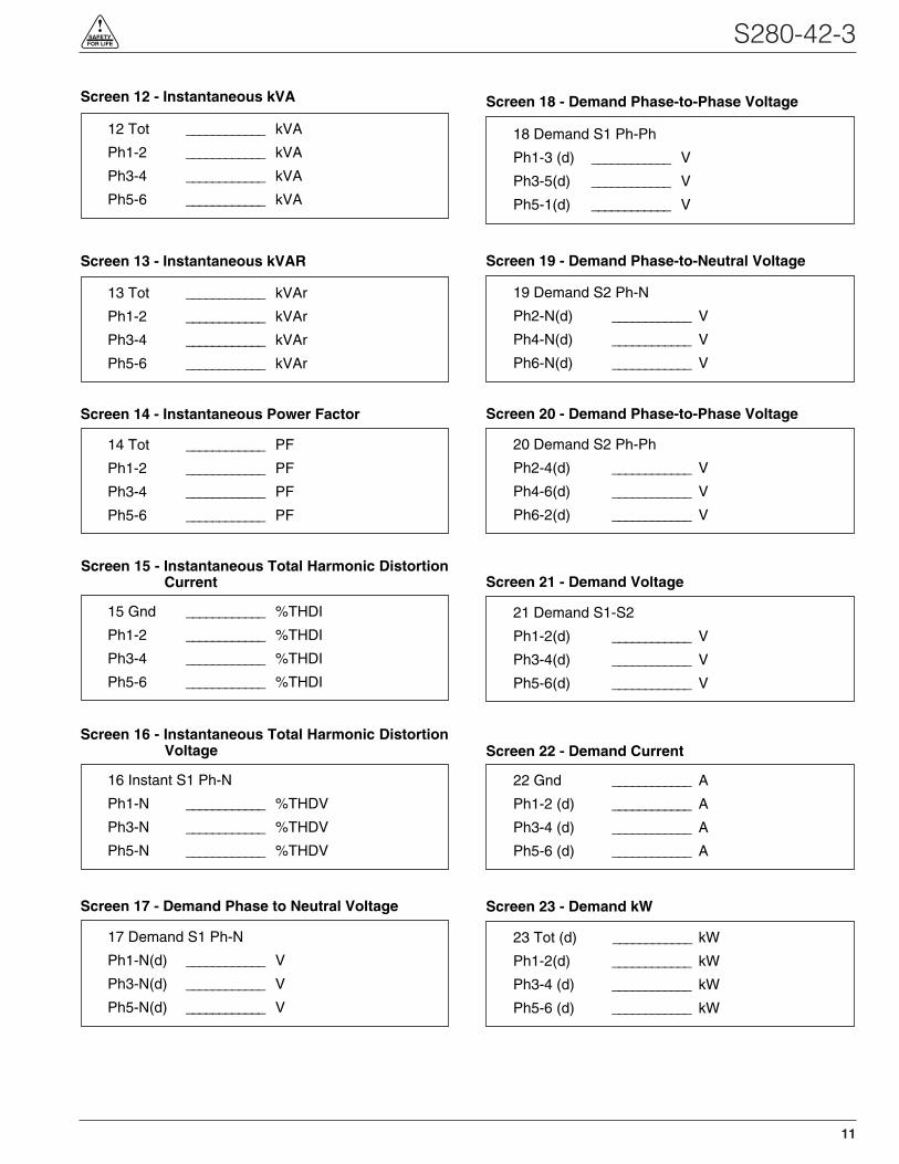
Screen 17 - Demand Phase to Neutral Voltage
Screen 18 - Demand Phase-to-Phase VoltageScreen 12 - Instantaneous kVA
Screen 19 - Demand Phase-to-Neutral VoltageScreen 13 - Instantaneous kVAR
Screen 20 - Demand Phase-to-Phase VoltageScreen 14 - Instantaneous Power Factor
Screen 15 - Instantaneous Total Harmonic DistortionCurrent
Screen 16 - Instantaneous Total Harmonic DistortionVoltage
21 Demand S1-S2
Ph1-2(d) ____________ V
Ph3-4(d) ____________ V
Ph5-6(d) ____________ V
Screen 21 - Demand Voltage
18 Demand S1 Ph-Ph
Ph1-3 (d) ____________ V
Ph3-5(d) ____________ V
Ph5-1(d) ____________ V
22 Gnd ____________ A
Ph1-2 (d) ____________ A
Ph3-4 (d) ____________ A
Ph5-6 (d) ____________ A
23 Tot (d) ____________ kW
Ph1-2(d) ____________ kW
Ph3-4 (d) ____________ kW
Ph5-6 (d) ____________ kW
Screen 22 - Demand Current
Screen 23 - Demand kW
Kyle Form 5/Triple-Single Microprocessor-Based Recloser Control Installation and Operation Instructions
12
24 Tot ____________ kVA
Ph1-2(d) ____________ kVA
Ph3-4(d) ____________ kVA
Ph5-6(d) ____________ kVA
25 Tot ____________ kVAr
Ph1-2(d) ____________ kVAr
Ph3-4(d) ____________ kVAr
Ph5-6(d) ____________ kVAr
26 Tot ____________ PF
Ph1-2(d) ____________ PF
Ph3-4(d) ____________ PF
Ph5-6(d) ____________ PF
27 Gnd ____________ %THDI
Ph1-2(d) ____________ %THDI
Ph3-4(d) ____________ %THDI
Ph5-6(d) ____________ %THDI
28 Demand S1 Ph-N
Ph1-N(d) ____________ %THDV
Ph3-N(d) ____________ %THDV
Ph5-N(d) ____________ %THDV
29 Gnd OC Trip ____________
Ph1-2 OC Trip ____________
Ph3-4 OCTrip ____________
Ph5-6 OC Trip ____________
30 SGF OC Trip ______
Ph1-2 Ops ______
Ph3-4 Ops ______
Ph5-6 Ops ______
31 Battery Monitor
Normal _______ V
Normal _____ mA
Test _______ V
32 – Phase MT ______ A
ALT1 MT ______ A
ALT2 MT ______ A
ALT3 MT ______ A
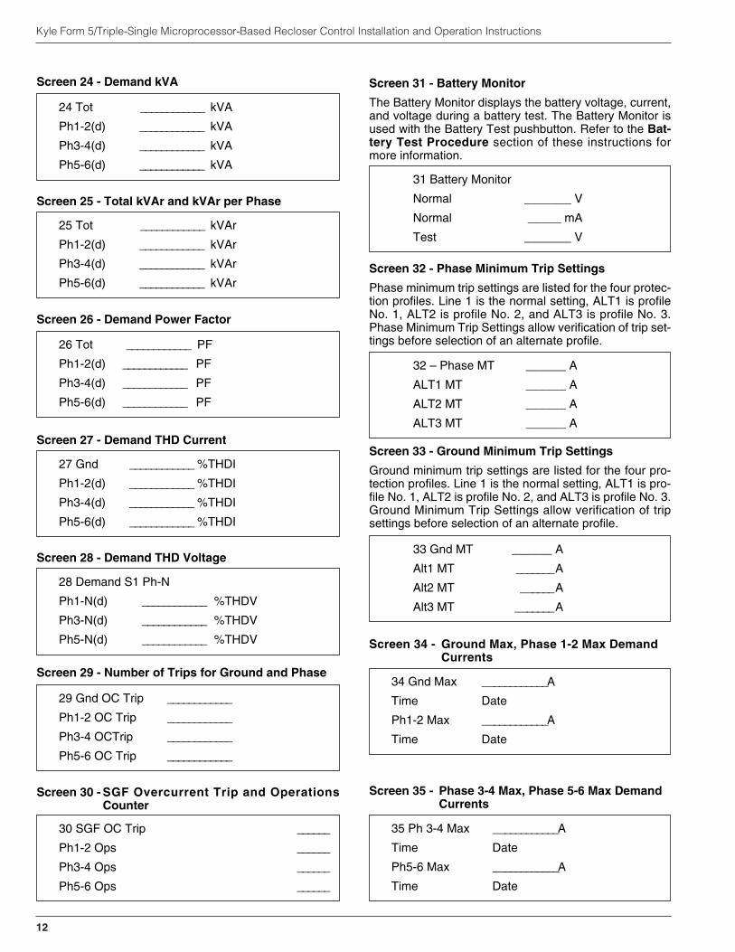
Screen 24 - Demand kVA
Screen 25 - Total kVAr and kVAr per Phase
Screen 26 - Demand Power Factor
Screen 27 - Demand THD Current
Screen 28 - Demand THD Voltage
Screen 29 - Number of Trips for Ground and Phase
Screen 30 - SGF Overcurrent Trip and OperationsCounter
Screen 31 - Battery Monitor
The Battery Monitor displays the battery voltage, current,and voltage during a battery test. The Battery Monitor isused with the Battery Test pushbutton. Refer to the Bat-tery Test Procedure section of these instructions formore information.
Screen 32 - Phase Minimum Trip Settings
Phase minimum trip settings are listed for the four protec-tion profiles. Line 1 is the normal setting, ALT1 is profileNo. 1, ALT2 is profile No. 2, and ALT3 is profile No. 3.Phase Minimum Trip Settings allow verification of trip set-tings before selection of an alternate profile.
35 Ph 3-4 Max ____________A
Time Date
Ph5-6 Max ____________A
Time Date
Screen 35 - Phase 3-4 Max, Phase 5-6 Max DemandCurrents
33 Gnd MT ______ A
Alt1 MT _______ A
Alt2 MT ______ A
Alt3 MT _______ A
34 Gnd Max ____________A
Time Date
Ph1-2 Max ____________A
Time Date
Screen 33 - Ground Minimum Trip Settings
Ground minimum trip settings are listed for the four pro-tection profiles. Line 1 is the normal setting, ALT1 is pro-file No. 1, ALT2 is profile No. 2, and ALT3 is profile No. 3.Ground Minimum Trip Settings allow verification of tripsettings before selection of an alternate profile.
Screen 34 - Ground Max, Phase 1-2 Max DemandCurrents
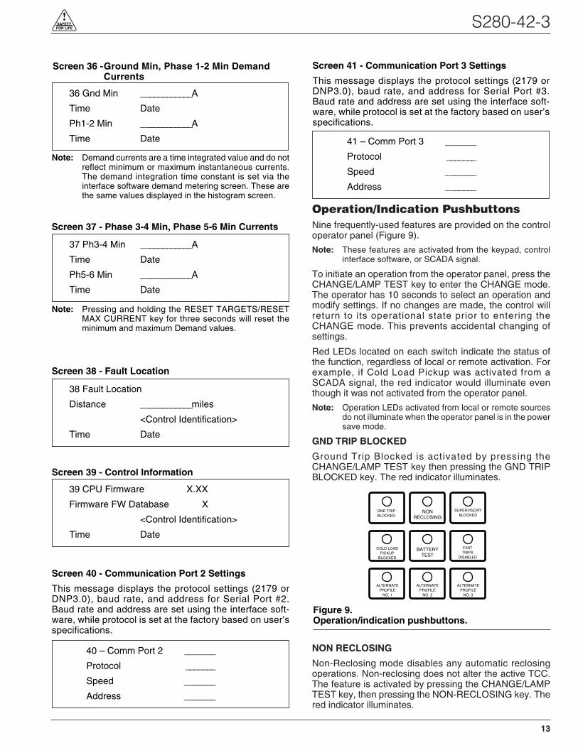
Operation/Indication PushbuttonsNine frequently-used features are provided on the controloperator panel (Figure 9).
Note: These features are activated from the keypad, controlinterface software, or SCADA signal.
To initiate an operation from the operator panel, press theCHANGE/LAMP TEST key to enter the CHANGE mode.The operator has 10 seconds to select an operation andmodify settings. If no changes are made, the control willreturn to its operational state prior to entering theCHANGE mode. This prevents accidental changing ofsettings.
Red LEDs located on each switch indicate the status ofthe function, regardless of local or remote activation. Forexample, if Cold Load Pickup was activated from aSCADA signal, the red indicator would illuminate eventhough it was not activated from the operator panel.
Note: Operation LEDs activated from local or remote sourcesdo not illuminate when the operator panel is in the powersave mode.
GND TRIP BLOCKED
Ground Trip Blocked is activated by pressing theCHANGE/LAMP TEST key then pressing the GND TRIPBLOCKED key. The red indicator illuminates.
NON RECLOSING
Non-Reclosing mode disables any automatic reclosingoperations. Non-reclosing does not alter the active TCC.The feature is activated by pressing the CHANGE/LAMPTEST key, then pressing the NON-RECLOSING key. Thered indicator illuminates.
S280-42-3
13
!SAFETYFOR LIFE
GND TRIPBLOCKED
NONRECLOSING
SUPERVISORYBLOCKED
COLD LOADPICKUP
BLOCKED
BATTERYTEST
FASTTRIPS
DISABLED
ALTERNATEPROFILE
NO. 1
ALTERNATEPROFILE
NO. 2
ALTERNATEPROFILE
NO. 3
Figure 9.Operation/indication pushbuttons.
37 Ph3-4 Min ____________A
Time Date
Ph5-6 Min ____________A
Time Date
40 – Comm Port 2 ______
Protocol _______
Speed _______
Address _______
41 – Comm Port 3 ______
Protocol _______
Speed _______
Address _______
36 Gnd Min ____________A
Time Date
Ph1-2 Min ____________A
Time Date
38 Fault Location
Distance ____________miles
<Control Identification>
Time Date
39 CPU Firmware X.XX
Firmware FW Database X
<Control Identification>
Time Date
Screen 38 - Fault Location
Screen 36 -Ground Min, Phase 1-2 Min DemandCurrents
Screen 39 - Control Information
Screen 40 - Communication Port 2 Settings
This message displays the protocol settings (2179 orDNP3.0), baud rate, and address for Serial Port #2.Baud rate and address are set using the interface soft-ware, while protocol is set at the factory based on user’sspecifications.
Screen 37 - Phase 3-4 Min, Phase 5-6 Min Currents
Screen 41 - Communication Port 3 Settings
This message displays the protocol settings (2179 orDNP3.0), baud rate, and address for Serial Port #3.Baud rate and address are set using the interface soft-ware, while protocol is set at the factory based on user’sspecifications.
Note: Demand currents are a time integrated value and do notreflect minimum or maximum instantaneous currents.The demand integration time constant is set via theinterface software demand metering screen. These arethe same values displayed in the histogram screen.
Note: Pressing and holding the RESET TARGETS/RESETMAX CURRENT key for three seconds will reset theminimum and maximum Demand values.
SUPERVISORY BLOCKED
SUPERVISORY BLOCKED disables supervisory SCADAand interface software; remote SCADA remains active.Operational data and metering information are availablewhile the control is in the SUPERVISORY BLOCKEDposition. The TRIP and CLOSE pushbuttons are activeindependently of the SUPERVISORY BLOCKED key.
Activation of the feature is restricted to the operator panelkeypad by pressing the CHANGE/LAMP TEST key, thenpressing the SUPERVISORY BLOCKED key.
COLD LOAD PICKUP BLOCKED
The Cold Load Pickup (CLPU) feature is blocked while theCLOD LOAD PICKUP BLOCKED IS active. When CLPU isnot blocked, the control utilizes the Cold Load Pickup TCC,reclose interval, operations to lockout and minimum trip set-tings in lieu of the normal first operation protection settings.
Note: The Cold Load Pickup Blocked key is replaced by theSENSITIVE GROUND FAULT (SGF) key on interna-tional controls.
BATTERY TEST
Depressing the BATTERY TEST key performs a controlbattery test. The red indicator illuminates and turns offautomatically when the control has finished performing thetest. Refer to Battery Testing and Charging Proceduresin the Testing section of this manual for more information.
The control performs a self-test every 12 hours or wheninitiated by an external command. When a battery test isinitiated, the spurious charge is first drained to allow thebattery voltage to equalize. A 10-ohm, 55-watt resistor isthen placed across the battery terminals and a voltagedrop is calculated. If the drop from the equalized voltageto the test voltage exceeds 2 volts, then the CHECK BAT-TERY LED is illuminated.
FAST TRIPS DISABLED
Fast Trips Disabled commands the control to use the pro-grammed Fast Trips Disabled time-current curve for alltripping operations.
ALTERNATE PROFILE Indicator/Key
The control has four separate protection profiles; a normalprofile, and Alternate Profiles 1, 2, and 3. Each profilechanges all protection parameters for the control. Except forthe normal profile, each has an indication and selection key.During control operation, if the three alternate profile indica-tor lights are not illuminated, the normal profile is active.
To select an alternate profile, press the CHANGE/LAMPTEST key, then press the desired alternate profile. Toreturn to the normal profile, simply turn off the active alter-nate profile. These functions can also be operatedremotely via communications interfaces.
Note: The minimum trip values for each protection profile areshown on Screens 32 and 33 of the LCD display. Checkthese minimum trip values prior to changing an alternateprofile to avoid misoperation of the control under loadconditions.
Note: On Form 5/Triple-Single UDP controls, Alternate Profile3 is replaced with SWITCH MODE. See FORM 5 LSUNIVERSAL DEVICE PROTECTION (UDP) section ofthis manual.
HOT LINE TAG ON/OFF Toggle Switchand LED Indicator
Hot Line Tag is provided for live-line work applications. Allclosing operations are disabled when the Hot Line Tagfeature is activated. While active, the control utilizes anindependent, user-selectable time-current curve for tripoperations.
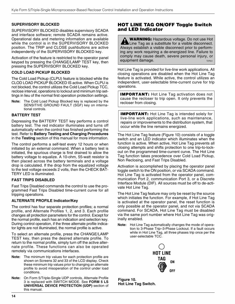
The Hot Line Tag feature (Figure 10) consists of a toggleswitch and an LED indicator which illuminates when thefunction is active. When active, Hot Line Tag prevents allclosing attempts and shifts protection to one trip-to-lock-out on the programmed time-current curve. The Hot LineTag function takes precedence over Cold Load Pickup,Non Reclosing, and Fast Trips Disabled.
Activation is accomplished by placing the operator paneltoggle switch to the ON position, or via SCADA command.Hot Line Tag is activated from the operator panel, com-munication Port 2, communication Port 3, or a DiscreteInterface Module (DIF). All sources must be off to de-acti-vate Hot Line Tag.
The Hot Line Tag feature may only be reset by the sourcewhich initiates the function. For example, if Hot Line Tagis activated at the operator panel, the reset function isonly possible at the operator panel, and not via SCADAcommand. For SCADA, Hot Line Tag must be disabledvia the same port number where Hot Line Tag was orig-inally enabled.
Note: Hot Line Tag automatically changes the mode of opera-tion to 3-Phase Trip–3-Phase Lockout. If a fault occurswhile in Hot Line Tag, all three phases trip once per theuser-selectable TCC.
Kyle Form 5/Triple-Single Microprocessor-Based Recloser Control Installation and Operation Instructions
14
HOT LINETAG
ON
OFF
Figure 10.Hot Line Tag Switch.
WARNING: Hazardous voltage. Do not use HotLine Tag as a substitute for a visible disconnect.
Always establish a visible disconnect prior to perform-ing any work requiring a de-energized line. Failure tocomply may cause death, severe personal injury, orequipment damage. T276.0
!
IMPORTANT: Hot Line Tag is intended solely forlive-line work applications, such as maintenance,repairs or improvements to the distribution system, thatoccur while the line remains energized.
IMPORTANT: Hot Line Tag activation does notcause the recloser to trip open. It only prevents therecloser from closing.
Manual Control OperationEach single-phase unit in the NOVA-TS Triple-Singlerecloser represents either A, B, or C phase. Phase selectionkeys (Figure 7) are used to select a phase that will operatewhen a manual TRIP or CLOSE operation is activated.
Note: Before selecting a phase for operation, press theCHANGE/LAMP TEST key.
Manual operation of the yellow handles on the NOVA-TStriple-single recloser is used to open and lockout thephases, and disable the electrical and supervisory clos-ing. The recloser mode of operation determines whichphases open and close. The Form 5/Triple-Single controlinitiates the close signal.
3Ø Trip – 3Ø Lockout (Mode A) or1Ø Trip – 3Ø Lockout (Mode B)If the control is in Three-Phase Trip – Three-Phase Lock-out (Mode A) or Single-Phase Trip – Three-Phase Lock-out (Mode B), all three phases are permanently selectedand all three PHASE SELECT LEDs are illuminated.
When one phase is opened with the yellow operating han-dle, all three phases open and lockout The OPEN andLOCKOUT LEDs illuminate on the control panel.
With the yellow operating handle of the appropriate phasein the CLOSE position, press the CLOSE pushbutton onthe control operator panel. All three phases close and theCLOSED LEDs for all three phases illuminate.
1Ø Trip – 1Ø Lockout (Mode C)When in Single-Phase Trip – Single-Phase Lockout(Mode C) any combination of phases can be selected andthe respective PHASE SELECT LED illuminates. Eachselected phase must be closed individually.
When the selected phase is opened with the yellow operat-ing handle, only that phase opens and locks out. The OPENand LOCKOUT LEDs illuminate on the control panel.
With the yellow operating handle of the selected phase inthe CLOSE position, press the CLOSE pushbutton on thecontrol panel. The phase closes and the CLOSED LED forthat phase illuminates.
Control FeaturesThe Form 5/Triple-Single recloser control offers numer-ous standard features and accessories that allow the userthe utmost flexibility in designing a control suitable fortheir application requirements.
Under/Over Frequency LoadsheddingThe Form 5/Triple-Single control includes provisions forfrequency loadshedding that trips the recloser for condi-tions of under or over system frequency. Access to thisfeature is through frequency threshold, trip time, andallowable voltage threshold.
With the auto-restoration feature, the Form 5/Triple-Singlecontrol can be set to close the recloser after the systemfrequency and voltage have recovered. Parameters avail-able for setting include frequency and voltage thresholdsand time delay.
A frequency alarm is available and can be configured fornotification.
S280-42-3
15
!SAFETYFOR LIFE
WARNING: Hazardous Voltage. Do not rely onthe open position of the yellow operating handle;
it does not ensure that the line has been de-energized.Always establish a visible disconnect. Failure to followproper safety practices can result in contact with highvoltage, which will cause death or severe personalinjury. G116.0
!
IMPORTANT: Pushing the yellow operating handleto the CLOSE position will not close the recloser. Allclose operations are initiated by the Form 5/Triple-Sin-gle control.
IMPORTANT: Pushing the yellow operating handle tothe CLOSE position will not close the recloser. All closeoperations are initiated by the Form 5/Triple-Single control.
IMPORTANT: If more than 5 minutes elapses since thelast panel operation, all the LEDs, except CONTROL OK,will turn off and all three phases will be selected. Deselectthe phases you do not want activated, and then press theTRIP or CLOSE button.

Voltage Protection (120 Vac-based)Voltage protection functionality is included as standard onForm 5/Triple-Single controls. A recloser trip is issued forunder and over voltage conditions when the monitoredvoltage falls outside user specified limits for a selectabletime. Response mode includes:
• any single-phase
• all three phases
• single-phase with three-phase inhibit.
Response mode facilitates protection against a singlephase condition common when a high-side fuse operateson a distribution transformer. Parameters are also avail-able to provide auto restoration after a trip. A voltagealarm is available and can be configured for notification.
Protection ProfilesFour separate protection profiles are included to allow theuser to adapt overcurrent settings for varying system con-ditions such as load, live line work or weather. The activeprofile is selected from the operator panel, the interfacesoftware or SCADA (see Figure 11). Each profile has 14TCC specifications plus reclose intervals, sequence coor-dination and reset times to maintain independent protec-tion parameters.
Power MeteringPower metering includes single- and three-phase Watts,VARS, KVARS, KWH measurements, and the per phaseand total system Power Factor (PF).
Power Factor Sign MeteringThis feature allows a user to configure the sign that isapplied to the power factor. The user selects between thedefinition of power factor (cosine of angle between currentand voltage) or the power factor sign following power flow.
Trip Failure DetectionThe Trip Failure Detection feature is an internal diagnos-tic alarm for verifying the proper operation of circuit trip-ping and fault clearing of the recloser. Trip Failuredetection indicates the recloser has failed to trip allphases following a trip signal from the control. Failure totrip is assumed if a current of at least 10 Amps is detectedapproximately 2 seconds after the trip signal is initiated.
Upon activation of the feature the following four LEDsflash 1 second on, 1 second off (see Figure 12):
RECLOSER MALFUNCTION
RECLOSER CLOSED
RECLOSER OPEN
CONTROL LOCKOUT
Kyle Form 5/Triple-Single Microprocessor-Based Recloser Control Installation and Operation Instructions
16
REVERSE POWER FLOW
RECLOSER MALFUNCTION
AØ FAULT TARGET
BØ FAULT TARGET
CØ FAULT TARGET
GROUND FAULT TARGET
SENSITIVE-GROUND FAULT TARGET
AØ VOLTAGE
BØ VOLTAGE
CØ VOLTAGE
1Ø TRIP - 1Ø LOCKOUT
1Ø TRIP - 3Ø LOCKOUT
3Ø TRIP - 3Ø LOCKOUT
CLOSETRIP(LOCKOUT)
CLOSED
OPEN
LOCKOUT
AØ
CLOSED
OPEN
LOCKOUT
BØ
CLOSED
OPEN
LOCKOUT
CØ
SELECT PHASES TO OPERATE
Figure 12.RECLOSER MALFUNCTION, OPEN, CLOSED, andLOCKOUT LEDs will blink for the affected phase asindication of Trip Failure.
Figure 11.Interface software sample protection profile.
DANGER: Explosion. Stay clear of a recloserthat is in a trip failure mode. A recloser in trip fail-
ure mode may explode resulting in death or severe per-sonal injury. T271.0
!
IMPORTANT: The recloser must be isolated and de-energized immediately upon detection of trip failure.Follow proper procedures and safety practices to iso-late and de-energize the recloser.
WARNING: Hazardous voltage. This device isnot a substitute for a visible disconnect. Follow all
locally approved safety practices. Failure to followproper safety practices can result in contact with highvoltage, which will cause death or severe personalinjury. G112.1
!
The Trip Failure Detection alarm may be triggered frommany potential sources including mechanical, electrical,control, or interrupter failure. Interrupter failure mayinclude loss of vacuum in a vacuum interrupter.
To clear Trip Failure Alarm, depress and hold the RESETTARGETS/RESET MAX CURRENTS keypad for 3 sec-onds. This also resets targets and demand currents.
Note: There is no remote reset available with the trip failuredetection feature. It cannot be remotely turned off.
When the trip failure alarm is activated, an event isrecorded and a status alarm activated (if enabled) andpreserved during system resets.
Manual Close DelayManual Close Delay provides a delay from the time thatthe manual CLOSE button is pushed to the time the man-ual close operation is performed. The CLOSED LED forthe affected phase blinks indicating the feature is active.See Figure 13.
The delay is programmable from 0 to 60 seconds in onesecond increments. A programmed delay value can beoverridden for immediate closing by pressing the CLOSEbutton a second time.
An active Manual Close Delay can be canceled by press-ing the TRIP/LOCKOUT button.
The default setting has the feature disabled (0 seconds).
Voltage MeteringSix voltages (3-source and 3-load) are metered as stan-dard on the Form 5/Triple-Single control. The user selectseither line-to-neutral or line-to-line values from the controloperator panel, interface software, or serial communica-tions. The type of value is changed by selecting “VoltageConfiguration” in the “Hardware” setup portion of the inter-face software.
Fast Trips DisabledFast Trips Disabled provides the user a quick and efficientmethod for reducing momentary interruptions or “blinks”.When activated from the front keypad (Figure 9), pro-grammed trips to lockout will time according to theselected time-current curve for Fast Trips Disabled. Thiscurve is programmable for both phase and ground oneach protection profile. A separate trips-to-lockout settingis also provided.
HistogramsDemand metered voltages and currents can be reportedusing the histogram tool. It displays the number of occur-rences of a variable versus its value within user-definedminimum and maximum limits. Date and time arerecorded for the maximum and minimum demand values.
Reverse Power FlowFeeder load monitoring is enhanced with the inclusion ofthe power flow monitoring feature. When power flow fromthe load to the source side of the recloser is detected, thecontrol and illuminates a front-panel indicator. Responsetime to a reverse power condition is one second. An alarmis also available for remote interrogation.
Note: Voltage sensor polarity must be correct for reversepower flow to function properly.
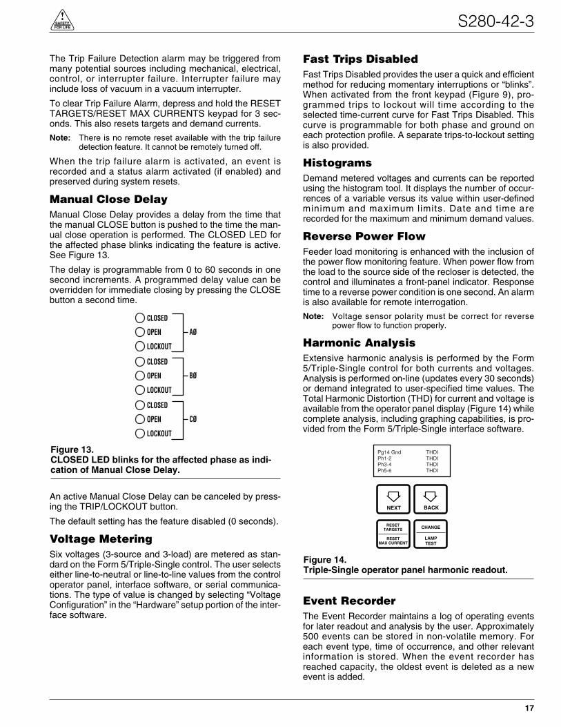
Harmonic AnalysisExtensive harmonic analysis is performed by the Form5/Triple-Single control for both currents and voltages.Analysis is performed on-line (updates every 30 seconds)or demand integrated to user-specified time values. TheTotal Harmonic Distortion (THD) for current and voltage isavailable from the operator panel display (Figure 14) whilecomplete analysis, including graphing capabilities, is pro-vided from the Form 5/Triple-Single interface software.
Event RecorderThe Event Recorder maintains a log of operating eventsfor later readout and analysis by the user. Approximately500 events can be stored in non-volatile memory. Foreach event type, time of occurrence, and other relevantinformation is stored. When the event recorder hasreached capacity, the oldest event is deleted as a newevent is added.
S280-42-3
17
!SAFETYFOR LIFE
Figure 14.Triple-Single operator panel harmonic readout.
NEXT BACK
RESETTARGETS CHANGE
Pg14 Gnd THDIPh1-2 THDIPh3-4 THDIPh5-6 THDI
RESETMAX CURRENT
LAMPTEST
CLOSED
OPEN
LOCKOUT
AØ
CLOSED
OPEN
LOCKOUT
BØ
CLOSED
OPEN
LOCKOUT
CØ
Figure 13.CLOSED LED blinks for the affected phase as indi-cation of Manual Close Delay.
Data ProfilerA fully-configurable data profiler is available which allowsthe user to collect information by sampling demand dataat selectable intervals. These time-stamped values canthen be plotted to determine weekly load profiles, dailyharmonic disturbances or hourly voltage fluctuations. Thedata profiler can provide more than 200 days of informa-tion, depending upon configuration parameters.
Cold Load PickupCold Load Pickup (CLPU) must be enabled through theinterface software (Figure 15) before it can be activatedremotely or from the CLOSE pushbutton on the operatorpanel. The CLPU feature provides the user with the abil-ity to alter protection for abnormal system conditions. It isactive for a programmable time interval which begins witheach manual close. Once this time elapses, protectionreverts back to the programmed sequence. Use the Form5/Triple-Single control interface software to program theactivation time and time-current characteristics applicablefor Cold-Load Pickup.
Note: When CLPU is active, the control utilizes the Cold LoadPickup TCC, reclose interval, operations to lockout andminimum trip settings in lieu of the normal protectionsettings.
AlarmsStatus and data alarms are available for many controlparameters such as voltage and current thresholds. Dataalarm function compares metered data to user-pro-grammed alarm high and low limits and issues an alarm ofuser-specified priority if limits are exceeded. The statusalarm function monitors status and issues an alarm ofuser-defined priority when the user-programmed alarmconditions are met. The alarms are reported via commu-nication ports and can be configured to trigger a data pro-file and event record. Alarms do not affect the protectionfunctions of the control.
Status alarms are included for Modes A, B, and C as wellas the following status alarms for each phase of the KyleType NOVA-TS Triple Single recloser:
• Open • Retry Fail
• Closed • Open Fail
• Lockout • Neither Open or Closed
• Close Retry Active • Yellow Handle Active
• Close Fail
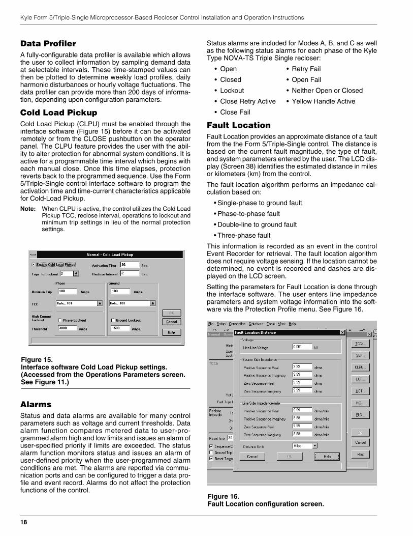
Fault LocationFault Location provides an approximate distance of a faultfrom the the Form 5/Triple-Single control. The distance isbased on the current fault magnitude, the type of fault,and system parameters entered by the user. The LCD dis-play (Screen 38) identifies the estimated distance in milesor kilometers (km) from the control.
The fault location algorithm performs an impedance cal-culation based on:
• Single-phase to ground fault
• Phase-to-phase fault
• Double-line to ground fault
• Three-phase fault
This information is recorded as an event in the controlEvent Recorder for retrieval. The fault location algorithmdoes not require voltage sensing. If the location cannot bedetermined, no event is recorded and dashes are dis-played on the LCD screen.
Setting the parameters for Fault Location is done throughthe interface software. The user enters line impedanceparameters and system voltage information into the soft-ware via the Protection Profile menu. See Figure 16.
Kyle Form 5/Triple-Single Microprocessor-Based Recloser Control Installation and Operation Instructions
18
Figure 15.Interface software Cold Load Pickup settings.(Accessed from the Operations Parameters screen.See Figure 11.)
Figure 16.Fault Location configuration screen.

The following system parameters must be entered via theProtection Profile menu for each profile:
• Nominal system line-to-line voltage
Note: If the Fault Location feature is not desired, the nom-inal system voltage parameter should be set at 1.
• Source-side zero sequence and positive sequenceimpedance. This includes impedance up to the loca-tion of the Form 5/Triple-Single control.
• Line-side zero sequence and positive sequenceimpedance per mile or km.
• The distance units of the line impedance in miles orkm.
Refer to Service Information S280-79-2 Form 5 Micropro-cessor-Based Recloser Control Programming Guide foradditional information.
Directional Sensitive Ground/Earth(SGF/SEF) FaultThe Directional SGF/SEF Fault feature adds directionalcapabilities to the SGF/SEF protection features. It pro-vides a sensitive ground/earth trip if the fault is downlineof the recloser on a radial distribution system. DirectionalSGF/SEF is used on ungrounded Delta systems for sup-pression of ground trips for faults occurring on other circuitbranches.
The user sets the parameters for Direction SGF/SEFthrough the interface software via the Protection Profilemenu. See Figure 17. In addition to the normal (non-direc-tional) SGF/SEF settings, the user enters the followingdirectional SGF/SEF parameters:
• Direction Enable
Note: If Direction Enable is not selected, SGF/SEF trippingoccurs through normal (non-directional) settings.
• Maximum Torque Angle (-180° to 180°, in 1° increments)
• Torque Angle Width (10° to 90°, in 1° increments)
• Zero Sequence Voltage (V0) Threshold (4 to 130 V)
The Maximum Torque Angle parameter determines theangle of maximum tripping sensitivity between the phaseangle of the zero sequence voltage and current at the timeof fault. The setting of this value depends on knowledgeof the power system. Typically a resistive fault has a valueof 0°, and a capacitive fault has a value of 90°.
Torque Angle Width parameter restricts the tripping to anangle of plus or minus the specified width about theTorque angle setting. For example, if the MaximumTorque Angle is 45°, and the Torque Angle Width is set for10°, then the control will trip at angles between 35° and55°.
The Zero Sequence Voltage Threshold is used to set thethreshold voltage below the disabled directional SGF/SEFtripping voltage.
Note: In most cases, a default value of 4 is adequate.
Directional SGF/SEF Fault is recorded as an event in thecontrol Event Recorder for retrieval. Refer to ServiceInformation S280-79-2 Form 5 Microprocessor-BasedRecloser Control Programming Guide for additionalinformation.
S280-42-3
19
!SAFETYFOR LIFE
IMPORTANT: Fault Location is not a protection func-tion. Its purpose is to define a fault and provide itsapproximate location relative to the Form 5/Triple-Sin-gle control detecting the fault.
Figure 17.Directional SGF/SEF configuration screen.
CommunicationsCommunication PortsThe Form 5/Triple-Single control has three communica-tion ports from the CPU module. Two of the three portsare user-accessible. Communication Port 1 is the opera-tor panel LCD display where data is exchanged betweenthe CPU and the operator panel. Though not-user-config-urable, Port 1 allows for flexible modifications to the frontpanel for custom applications.
The operator panel RS-232 communication Port 2 pro-vides temporary local personal computer (PC) accesswhen connected with a standard 9-pin cable. Port 2 pro-vides a dual communication interface for the user. Theport includes a software switch for two external connec-tions; the operator panel RS-232 DB-9 connector, or thefiber-optic/RS-232 communication accessories. Localconnection to the operator panel RS-232 connectiontakes precedence over the communication accessory.Disconnecting the operator panel RS-232 communicationautomatically reconnects the communication accessoryto Port 2.
Accessory Ports 2 and 3 are resident on the back of theoperator panel and can be configured to either 2179 orDNP3.0 protocols. Port 3 provides uninterrupted commu-nication to the RS-232 or Fiber-Optic accessory, and isnot affected by any other port or physical connection.
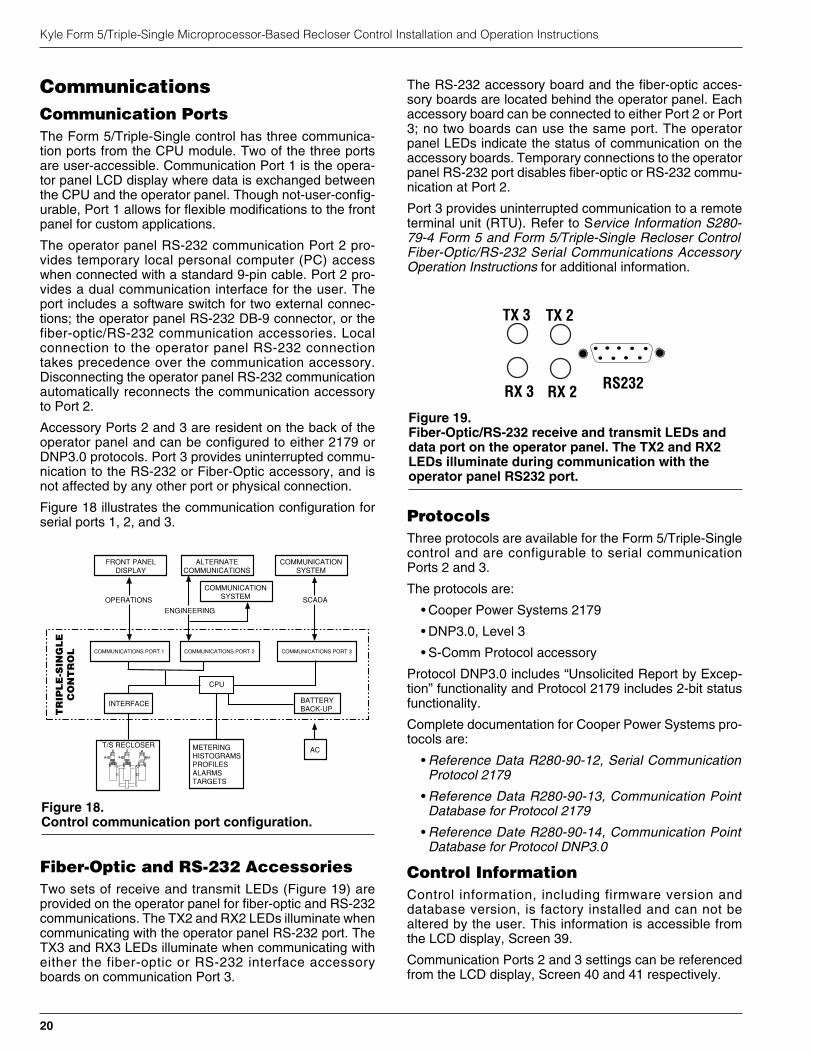
Figure 18 illustrates the communication configuration forserial ports 1, 2, and 3.
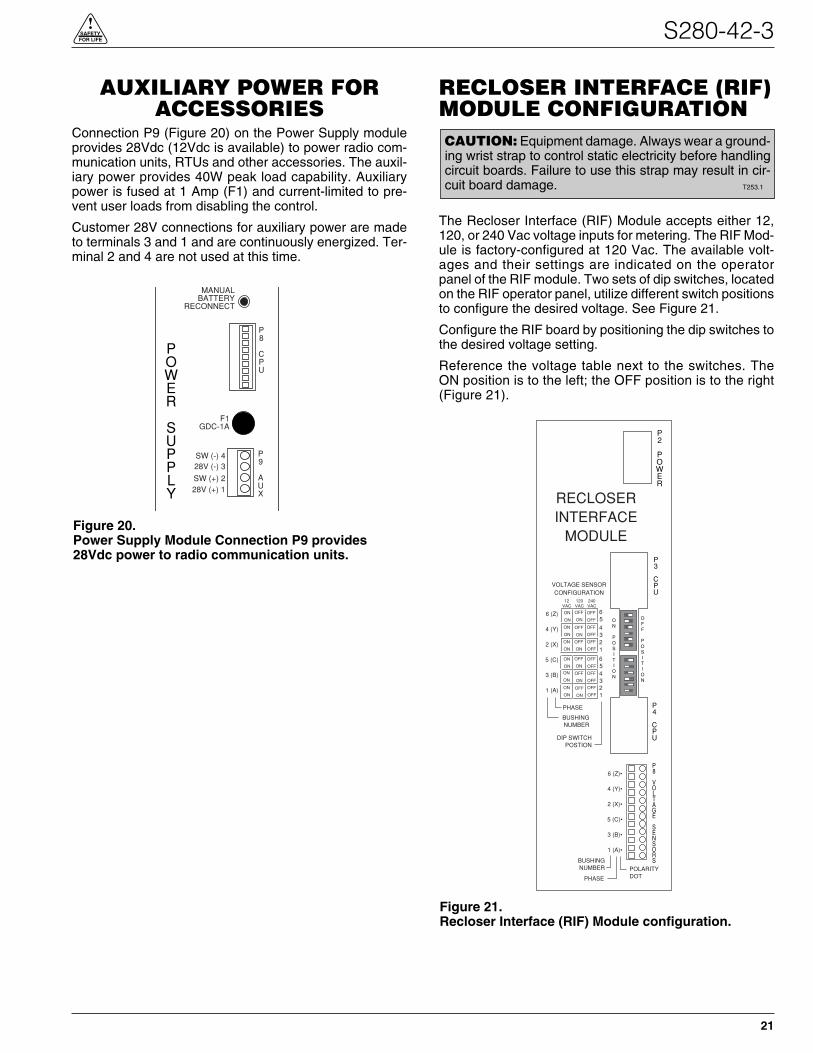
Fiber-Optic and RS-232 AccessoriesTwo sets of receive and transmit LEDs (Figure 19) areprovided on the operator panel for fiber-optic and RS-232communications. The TX2 and RX2 LEDs illuminate whencommunicating with the operator panel RS-232 port. TheTX3 and RX3 LEDs illuminate when communicating witheither the fiber-optic or RS-232 interface accessoryboards on communication Port 3.
The RS-232 accessory board and the fiber-optic acces-sory boards are located behind the operator panel. Eachaccessory board can be connected to either Port 2 or Port3; no two boards can use the same port. The operatorpanel LEDs indicate the status of communication on theaccessory boards. Temporary connections to the operatorpanel RS-232 port disables fiber-optic or RS-232 commu-nication at Port 2.
Port 3 provides uninterrupted communication to a remoteterminal unit (RTU). Refer to Service Information S280-79-4 Form 5 and Form 5/Triple-Single Recloser ControlFiber-Optic/RS-232 Serial Communications AccessoryOperation Instructions for additional information.
ProtocolsThree protocols are available for the Form 5/Triple-Singlecontrol and are configurable to serial communicationPorts 2 and 3.
The protocols are:
• Cooper Power Systems 2179
• DNP3.0, Level 3
• S-Comm Protocol accessory
Protocol DNP3.0 includes “Unsolicited Report by Excep-tion” functionality and Protocol 2179 includes 2-bit statusfunctionality.
Complete documentation for Cooper Power Systems pro-tocols are:
• Reference Data R280-90-12, Serial CommunicationProtocol 2179
• Reference Data R280-90-13, Communication PointDatabase for Protocol 2179
• Reference Date R280-90-14, Communication PointDatabase for Protocol DNP3.0
Control InformationControl information, including firmware version anddatabase version, is factory installed and can not bealtered by the user. This information is accessible fromthe LCD display, Screen 39.
Communication Ports 2 and 3 settings can be referencedfrom the LCD display, Screen 40 and 41 respectively.
Kyle Form 5/Triple-Single Microprocessor-Based Recloser Control Installation and Operation Instructions
20
TR
IPL
E-S
ING
LE
CO
NT
RO
L
AC
COMMUNICATIONS PORT 1 COMMUNICATIONS PORT 2 COMMUNICATIONS PORT 3
METERINGHISTOGRAMSPROFILESALARMSTARGETS
T/S RECLOSER
BATTERYBACK-UP
INTERFACE
CPU
ALTERNATECOMMUNICATIONS
ENGINEERING
FRONT PANELDISPLAY
OPERATIONS
COMMUNICATIONSYSTEM
SCADA
CLOSEDCLOSED
COMMUNICATIONSYSTEM
Figure 18.Control communication port configuration.
TX 2
RX 2
TX 3
RX 3 RS232
Figure 19.Fiber-Optic/RS-232 receive and transmit LEDs anddata port on the operator panel. The TX2 and RX2LEDs illuminate during communication with theoperator panel RS232 port.
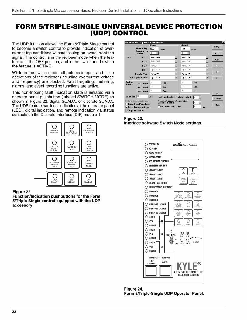
AUXILIARY POWER FORACCESSORIES
Connection P9 (Figure 20) on the Power Supply moduleprovides 28Vdc (12Vdc is available) to power radio com-munication units, RTUs and other accessories. The auxil-iary power provides 40W peak load capability. Auxiliarypower is fused at 1 Amp (F1) and current-limited to pre-vent user loads from disabling the control.
Customer 28V connections for auxiliary power are madeto terminals 3 and 1 and are continuously energized. Ter-minal 2 and 4 are not used at this time.
RECLOSER INTERFACE (RIF)MODULE CONFIGURATION
The Recloser Interface (RIF) Module accepts either 12,120, or 240 Vac voltage inputs for metering. The RIF Mod-ule is factory-configured at 120 Vac. The available volt-ages and their settings are indicated on the operatorpanel of the RIF module. Two sets of dip switches, locatedon the RIF operator panel, utilize different switch positionsto configure the desired voltage. See Figure 21.
Configure the RIF board by positioning the dip switches tothe desired voltage setting.
Reference the voltage table next to the switches. TheON position is to the left; the OFF position is to the right(Figure 21).
S280-42-3
21
!SAFETYFOR LIFE
CAUTION: Equipment damage. Always wear a ground-ing wrist strap to control static electricity before handlingcircuit boards. Failure to use this strap may result in cir-cuit board damage. T253.1
OFF
POSITION
P2
POWER
P3
CPU
P4
CPU
ON
POSITION
6 (Z)
4 (Y)
2 (X)
5 (C)
3 (B)
1 (A)
BUSHINGNUMBER
PHASE
VOLTAGE SENSORCONFIGURATION
12VAC
120VAC
240VAC
654321
654321
ON
ON
ON
ON
ON
ON
ON
ON
ON
ON
ON
ON
OFF
ON
OFF
ON
OFF
ON
OFF
ON
OFF
ON
OFF
ON
OFF
OFF
OFF
OFF
OFF
OFF
OFF
OFF
OFF
OFF
OFF
OFF
DIP SWITCHPOSTION
6 (Z)•
4 (Y)•
2 (X)•
5 (C)•
3 (B)•
1 (A)•
BUSHINGNUMBER
RECLOSERINTERFACE
MODULE
POLARITYDOTPHASE
S7
P8
VOLTAGE
SENSORS
Figure 21.Recloser Interface (RIF) Module configuration.
POWER
SUPPLY
P9
AUX
F1GDC-1A
P8
CPU
MANUALBATTERY
RECONNECT
SW (-) 428V (-) 3
SW (+) 228V (+) 1
Figure 20.Power Supply Module Connection P9 provides28Vdc power to radio communication units.
The UDP function allows the Form 5/Triple-Single controlto become a switch control to provide indication of over-current trip conditions without issuing an overcurrent tripsignal. The control is in the recloser mode when the fea-ture is in the OFF position, and in the switch mode whenthe feature is ACTIVE.
While in the switch mode, all automatic open and closeoperations of the recloser (including overcurrent voltageand frequency) are blocked. Fault targeting, metering,alarms, and event recording functions are active.
This non-tripping fault indication state is initiated via aoperator panel pushbutton (labeled SWITCH MODE) asshown in Figure 22, digital SCADA, or discrete SCADA.The UDP feature has local indication at the operator panel(LED), digital indication, and remote indication via statuscontacts on the Discrete Interface (DIF) module 1.
Kyle Form 5/Triple-Single Microprocessor-Based Recloser Control Installation and Operation Instructions
22
Figure 23.Interface software Switch Mode settings.
GND TRIPBLOCKED
NONRECLOSING
SUPERVISORYBLOCKED
COLD LOADPICKUP
BLOCKED
BATTERYTEST
FASTTRIPS
DISABLED
ALTERNATEPROFILE
NO. 1
ALTERNATEPROFILE
NO. 2
SWITCHMODE
AØSELECT
BØSELECT
CØSELECT
Figure 22.Function/Indication pushbuttons for the Form5/Triple-Single control equipped with the UDPaccessory.
FORM 5/TRIPLE-SINGLE UNIVERSAL DEVICE PROTECTION(UDP) CONTROL
CONTROL OK
AC POWER
ABOVE MIN TRIP
REVERSE POWER FLOW
RECLOSER MALFUNCTION
CHECK BATTERY
AØ FAULT TARGET
BØ FAULT TARGET
CØ FAULT TARGET
GROUND FAULT TARGET
SENSITIVE-GROUND FAULT TARGET
AØ VOLTAGE
BØ VOLTAGE
CØ VOLTAGE
1Ø TRIP - 1Ø LOCKOUT
1Ø TRIP - 3Ø LOCKOUT
3Ø TRIP - 3Ø LOCKOUT
CLOSETRIP(LOCKOUT) KYLE®
FORM 5/TRIPLE-SINGLE UDPRECLOSER CONTROL
TX 2
RX 2
TX 3
RX 3
BACK NEXT
LAMPTEST
CHANGERESET
TARGETS
RESETMAX CURRENT
GND TRIPBLOCKED
NONRECLOSING
SUPERVISORYBLOCKED
COLD LOADPICK UP
BLOCKED
BATTERYTEST
FASTTRIPS
DISABLED
ALTERNATEPROFILE
NO. 1
ALTERNATEPROFILE
NO. 2
SWITCHMODE
AØSELECT
BØSELECT
CØSELECT
CLOSED
OPEN
LOCKOUT
AØ
CLOSED
OPEN
LOCKOUT
BØ
CLOSED
OPEN
LOCKOUT
CØ
SELECT PHASES TO OPERATE
RS232
HOT LINETAG
ON
OFF
Figure 24.Form 5/Triple-Single UDP Operator Panel.
S280-42-3
23
!SAFETYFOR LIFE
DISCRETE INTERFACE (DIF)ACCESSORY
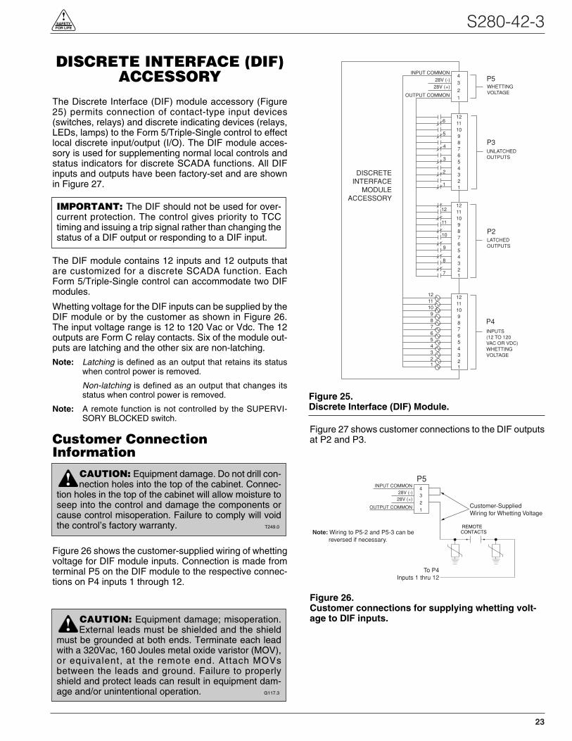
The Discrete Interface (DIF) module accessory (Figure25) permits connection of contact-type input devices(switches, relays) and discrete indicating devices (relays,LEDs, lamps) to the Form 5/Triple-Single control to effectlocal discrete input/output (I/O). The DIF module acces-sory is used for supplementing normal local controls andstatus indicators for discrete SCADA functions. All DIFinputs and outputs have been factory-set and are shownin Figure 27.
The DIF module contains 12 inputs and 12 outputs thatare customized for a discrete SCADA function. EachForm 5/Triple-Single control can accommodate two DIFmodules.
Whetting voltage for the DIF inputs can be supplied by theDIF module or by the customer as shown in Figure 26.The input voltage range is 12 to 120 Vac or Vdc. The 12outputs are Form C relay contacts. Six of the module out-puts are latching and the other six are non-latching.
Note: Latching is defined as an output that retains its statuswhen control power is removed.
Non-latching is defined as an output that changes itsstatus when control power is removed.
Note: A remote function is not controlled by the SUPERVI-SORY BLOCKED switch.
Customer ConnectionInformation
Figure 26 shows the customer-supplied wiring of whettingvoltage for DIF module inputs. Connection is made fromterminal P5 on the DIF module to the respective connec-tions on P4 inputs 1 through 12.
Figure 27 shows customer connections to the DIF outputsat P2 and P3.
4
3
2
1
4321
8765
1211109
6
5
4
3
2
1
4321
8765
1211109
12
11
10
9
8
7
4321
8765
1211109
INPUT COMMON
28V (-)28V (+)
OUTPUT COMMON
P5
P3
P2
P4
DISCRETEINTERFACE
MODULEACCESSORY
WHETTINGVOLTAGE
UNLATCHEDOUTPUTS
LATCHEDOUTPUTS
INPUTS(12 TO 120VAC OR VDC)WHETTINGVOLTAGE
4321
8765
1211109
Figure 25.Discrete Interface (DIF) Module.
4
3
2
1
INPUT COMMON
28V (-)28V (+)
OUTPUT COMMON
To P4Inputs 1 thru 12
P5
Customer-SuppliedWiring for Whetting Voltage
REMOTECONTACTSNote: Wiring to P5-2 and P5-3 can be
reversed if necessary.
Figure 26.Customer connections for supplying whetting volt-age to DIF inputs.CAUTION: Equipment damage; misoperation.
External leads must be shielded and the shieldmust be grounded at both ends. Terminate each leadwith a 320Vac, 160 Joules metal oxide varistor (MOV),or equivalent, at the remote end. Attach MOVsbetween the leads and ground. Failure to properlyshield and protect leads can result in equipment dam-age and/or unintentional operation. G117.3
!
CAUTION: Equipment damage. Do not drill con-nection holes into the top of the cabinet. Connec-
tion holes in the top of the cabinet will allow moisture toseep into the control and damage the components orcause control misoperation. Failure to comply will voidthe control’s factory warranty. T249.0
!
IMPORTANT: The DIF should not be used for over-current protection. The control gives priority to TCCtiming and issuing a trip signal rather than changing thestatus of a DIF output or responding to a DIF input.
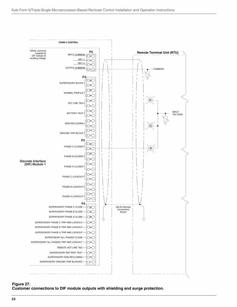
Kyle Form 5/Triple-Single Microprocessor-Based Recloser Control Installation and Operation Instructions
24
R
R
FORM 5 CONTROL
Remote Terminal Unit (RTU)
GROUND TRIP BLOCK
NON-RECLOSING
BATTERY TEST
INPUT COMMON
SUPERVISORY NON-RECLOSING
SUPERVISORY GROUND TRIP BLOCKED
Not All RemoteConnections
Shown
INPUTVOLTAGE
COMMON*
67
85
12
43
910
1112
Discrete Interface(DIF) Module 1
SUPERVISORY BATTERY TEST
REMOTE HOT LINE TAG
SUPERVISORY ALL PHASES TRIP AND LOCKOUT
SUPERVISORY ALL PHASED CLOSE
SUPERVISORY PHASE A TRIP AND LOCKOUT
SUPERVISORY PHASE B TRIP AND LOCKOUT
SUPERVISORY PHASE C TRIP AND LOCKOUT
SUPERVISORY PHASE A CLOSE
SUPERVISORY PHASE B CLOSE
SUPERVISORY PHASE C CLOSE
HOT LINE TAG
NORMAL PROFILE
SUPERVISORY BLOCK
PHASE A LOCKOUT
PHASE B LOCKOUT
PHASE C LOCKOUT
PHASE A CLOSED
PHASE B CLOSED
PHASE C CLOSED
P5
P3
P4
P2
G
28V (-)
28V (+)
OUTPUT COMMON
67
85
12
43
910
1112
67
85
12
43
910
1112
12
34
*28Vdc (nominal)supplied by
DIF module forwhetting voltage.
Figure 27.Customer connections to DIF module outputs with shielding and surge protection.
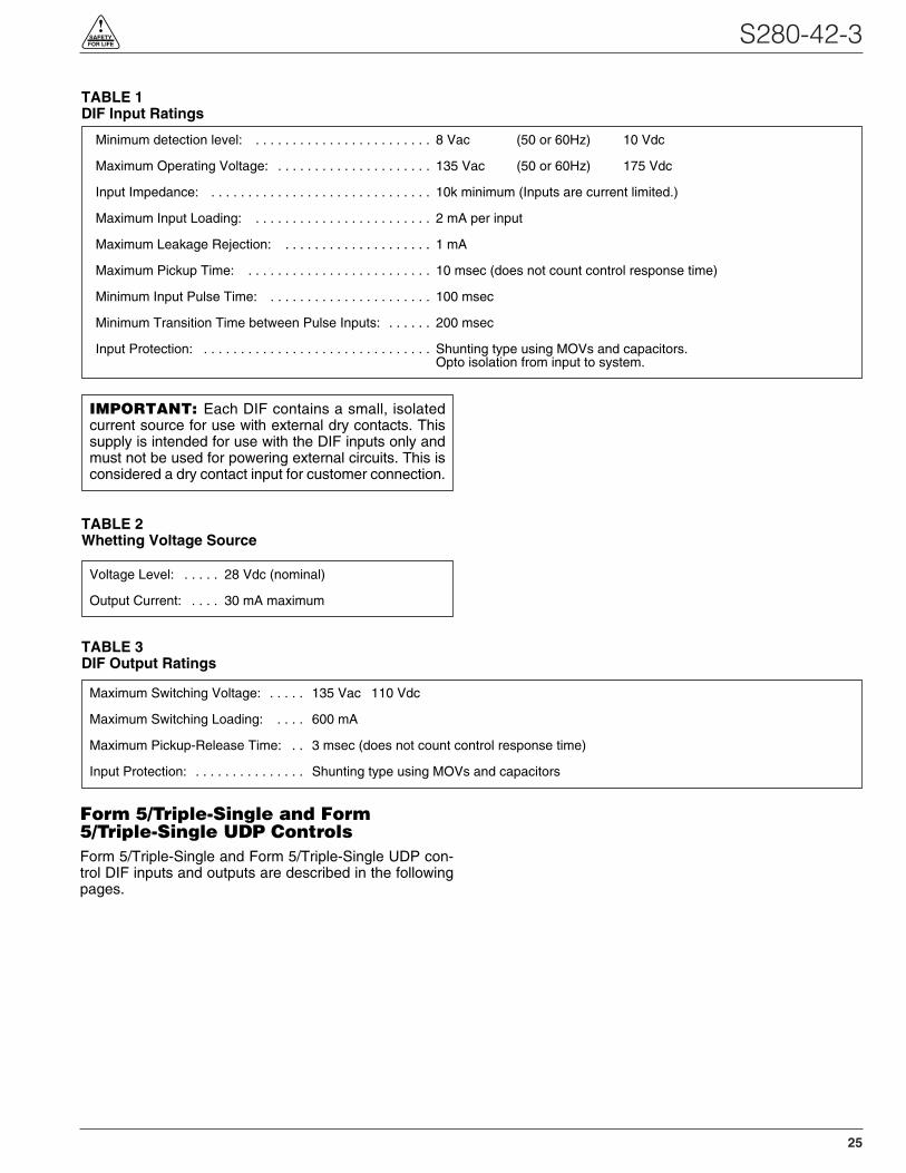
S280-42-3
25
!SAFETYFOR LIFE
Form 5/Triple-Single and Form5/Triple-Single UDP ControlsForm 5/Triple-Single and Form 5/Triple-Single UDP con-trol DIF inputs and outputs are described in the followingpages.
Maximum Switching Voltage: . . . . . 135 Vac 110 Vdc
Maximum Switching Loading: . . . . 600 mA
Maximum Pickup-Release Time: . . 3 msec (does not count control response time)
Input Protection: . . . . . . . . . . . . . . . Shunting type using MOVs and capacitors
Minimum detection level: . . . . . . . . . . . . . . . . . . . . . . . . 8 Vac (50 or 60Hz) 10 Vdc
Maximum Operating Voltage: . . . . . . . . . . . . . . . . . . . . . 135 Vac (50 or 60Hz) 175 Vdc
Input Impedance: . . . . . . . . . . . . . . . . . . . . . . . . . . . . . . 10k minimum (Inputs are current limited.)
Maximum Input Loading: . . . . . . . . . . . . . . . . . . . . . . . . 2 mA per input
Maximum Leakage Rejection: . . . . . . . . . . . . . . . . . . . . 1 mA
Maximum Pickup Time: . . . . . . . . . . . . . . . . . . . . . . . . . 10 msec (does not count control response time)
Minimum Input Pulse Time: . . . . . . . . . . . . . . . . . . . . . . 100 msec
Minimum Transition Time between Pulse Inputs: . . . . . . 200 msec
Input Protection: . . . . . . . . . . . . . . . . . . . . . . . . . . . . . . . Shunting type using MOVs and capacitors.Opto isolation from input to system.
Voltage Level: . . . . . 28 Vdc (nominal)
Output Current: . . . . 30 mA maximum
TABLE 1DIF Input Ratings
TABLE 2Whetting Voltage Source
TABLE 3DIF Output Ratings
IMPORTANT: Each DIF contains a small, isolatedcurrent source for use with external dry contacts. Thissupply is intended for use with the DIF inputs only andmust not be used for powering external circuits. This isconsidered a dry contact input for customer connection.
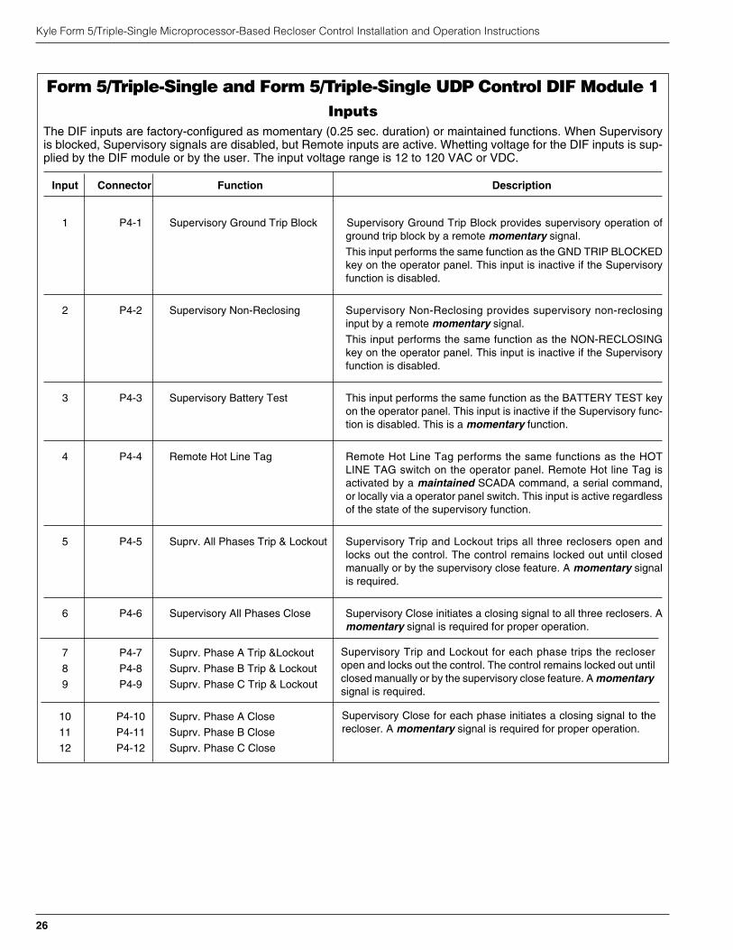
Kyle Form 5/Triple-Single Microprocessor-Based Recloser Control Installation and Operation Instructions
26
Form 5/Triple-Single and Form 5/Triple-Single UDP Control DIF Module 1Inputs
The DIF inputs are factory-configured as momentary (0.25 sec. duration) or maintained functions. When Supervisoryis blocked, Supervisory signals are disabled, but Remote inputs are active. Whetting voltage for the DIF inputs is sup-plied by the DIF module or by the user. The input voltage range is 12 to 120 VAC or VDC.
Input Connector Function Description
1 P4-1 Supervisory Ground Trip Block Supervisory Ground Trip Block provides supervisory operation ofground trip block by a remote momentary signal.
This input performs the same function as the GND TRIP BLOCKEDkey on the operator panel. This input is inactive if the Supervisoryfunction is disabled.
2 P4-2 Supervisory Non-Reclosing Supervisory Non-Reclosing provides supervisory non-reclosinginput by a remote momentary signal.
This input performs the same function as the NON-RECLOSINGkey on the operator panel. This input is inactive if the Supervisoryfunction is disabled.
3 P4-3 Supervisory Battery Test This input performs the same function as the BATTERY TEST keyon the operator panel. This input is inactive if the Supervisory func-tion is disabled. This is a momentary function.
4 P4-4 Remote Hot Line Tag Remote Hot Line Tag performs the same functions as the HOTLINE TAG switch on the operator panel. Remote Hot line Tag isactivated by a maintained SCADA command, a serial command,or locally via a operator panel switch. This input is active regardlessof the state of the supervisory function.
5 P4-5 Suprv. All Phases Trip & Lockout Supervisory Trip and Lockout trips all three reclosers open andlocks out the control. The control remains locked out until closedmanually or by the supervisory close feature. A momentary signalis required.
6 P4-6 Supervisory All Phases Close Supervisory Close initiates a closing signal to all three reclosers. Amomentary signal is required for proper operation.
7 P4-7 Suprv. Phase A Trip &Lockout
8 P4-8 Suprv. Phase B Trip & Lockout
9 P4-9 Suprv. Phase C Trip & Lockout
10 P4-10 Suprv. Phase A Close
11 P4-11 Suprv. Phase B Close
12 P4-12 Suprv. Phase C Close
Supervisory Trip and Lockout for each phase trips the recloseropen and locks out the control. The control remains locked out untilclosed manually or by the supervisory close feature. A momentarysignal is required.
Supervisory Close for each phase initiates a closing signal to therecloser. A momentary signal is required for proper operation.
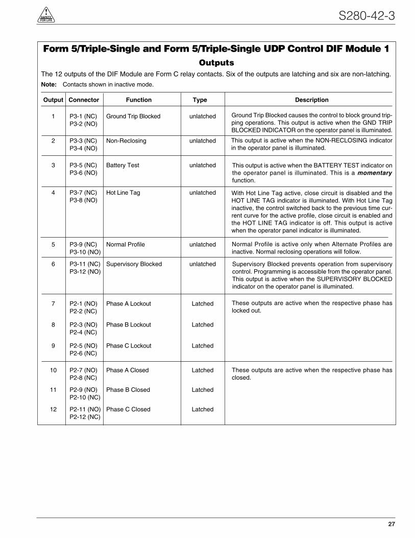
S280-42-3
27
!SAFETYFOR LIFE
Form 5/Triple-Single and Form 5/Triple-Single UDP Control DIF Module 1Outputs
The 12 outputs of the DIF Module are Form C relay contacts. Six of the outputs are latching and six are non-latching.
Note: Contacts shown in inactive mode.
Output Connector Function Type Description
1 P3-1 (NC) Ground Trip Blocked unlatchedP3-2 (NO)
2 P3-3 (NC) Non-Reclosing unlatchedP3-4 (NO)
3 P3-5 (NC) Battery Test unlatchedP3-6 (NO)
4 P3-7 (NC) Hot Line Tag unlatchedP3-8 (NO)
5 P3-9 (NC) Normal Profile unlatchedP3-10 (NO)
6 P3-11 (NC) Supervisory Blocked unlatchedP3-12 (NO)
7 P2-1 (NO) Phase A Lockout LatchedP2-2 (NC)
8 P2-3 (NO) Phase B Lockout LatchedP2-4 (NC)
9 P2-5 (NO) Phase C Lockout LatchedP2-6 (NC)
10 P2-7 (NO) Phase A Closed LatchedP2-8 (NC)
11 P2-9 (NO) Phase B Closed LatchedP2-10 (NC)
12 P2-11 (NO) Phase C Closed LatchedP2-12 (NC)
Normal Profile is active only when Alternate Profiles areinactive. Normal reclosing operations will follow.
This output is active when the NON-RECLOSING indicatorin the operator panel is illuminated.
Supervisory Blocked prevents operation from supervisorycontrol. Programming is accessible from the operator panel.This output is active when the SUPERVISORY BLOCKEDindicator on the operator panel is illuminated.
With Hot Line Tag active, close circuit is disabled and theHOT LINE TAG indicator is illuminated. With Hot Line Taginactive, the control switched back to the previous time cur-rent curve for the active profile, close circuit is enabled andthe HOT LINE TAG indicator is off. This output is activewhen the operator panel indicator is illuminated.
Ground Trip Blocked causes the control to block ground trip-ping operations. This output is active when the GND TRIPBLOCKED INDICATOR on the operator panel is illuminated.
This output is active when the BATTERY TEST indicator onthe operator panel is illuminated. This is a momentaryfunction.
These outputs are active when the respective phase haslocked out.
These outputs are active when the respective phase hasclosed.
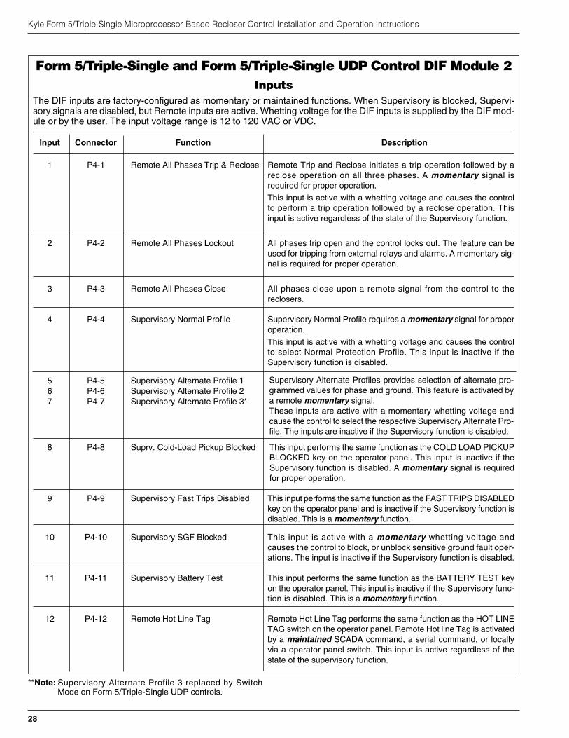
**Note: Supervisory Alternate Profile 3 replaced by SwitchMode on Form 5/Triple-Single UDP controls.
Kyle Form 5/Triple-Single Microprocessor-Based Recloser Control Installation and Operation Instructions
28
Form 5/Triple-Single and Form 5/Triple-Single UDP Control DIF Module 2Inputs
The DIF inputs are factory-configured as momentary or maintained functions. When Supervisory is blocked, Supervi-sory signals are disabled, but Remote inputs are active. Whetting voltage for the DIF inputs is supplied by the DIF mod-ule or by the user. The input voltage range is 12 to 120 VAC or VDC.
Input Connector Function Description
1 P4-1 Remote All Phases Trip & Reclose Remote Trip and Reclose initiates a trip operation followed by areclose operation on all three phases. A momentary signal isrequired for proper operation.
This input is active with a whetting voltage and causes the controlto perform a trip operation followed by a reclose operation. Thisinput is active regardless of the state of the Supervisory function.
2 P4-2 Remote All Phases Lockout All phases trip open and the control locks out. The feature can beused for tripping from external relays and alarms. A momentary sig-nal is required for proper operation.
3 P4-3 Remote All Phases Close All phases close upon a remote signal from the control to thereclosers.
4 P4-4 Supervisory Normal Profile Supervisory Normal Profile requires a momentary signal for properoperation.
This input is active with a whetting voltage and causes the controlto select Normal Protection Profile. This input is inactive if theSupervisory function is disabled.
5 P4-5 Supervisory Alternate Profile 16 P4-6 Supervisory Alternate Profile 27 P4-7 Supervisory Alternate Profile 3*
8 P4-8 Suprv. Cold-Load Pickup Blocked This input performs the same function as the COLD LOAD PICKUPBLOCKED key on the operator panel. This input is inactive if theSupervisory function is disabled. A momentary signal is requiredfor proper operation.
9 P4-9 Supervisory Fast Trips Disabled This input performs the same function as the FAST TRIPS DISABLEDkey on the operator panel and is inactive if the Supervisory function isdisabled. This is a momentary function.
10 P4-10 Supervisory SGF Blocked This input is active with a momentary whetting voltage andcauses the control to block, or unblock sensitive ground fault oper-ations. The input is inactive if the Supervisory function is disabled.
11 P4-11 Supervisory Battery Test This input performs the same function as the BATTERY TEST keyon the operator panel. This input is inactive if the Supervisory func-tion is disabled. This is a momentary function.
12 P4-12 Remote Hot Line Tag Remote Hot Line Tag performs the same function as the HOT LINETAG switch on the operator panel. Remote Hot line Tag is activatedby a maintained SCADA command, a serial command, or locallyvia a operator panel switch. This input is active regardless of thestate of the supervisory function.
Supervisory Alternate Profiles provides selection of alternate pro-grammed values for phase and ground. This feature is activated bya remote momentary signal.These inputs are active with a momentary whetting voltage andcause the control to select the respective Supervisory Alternate Pro-file. The inputs are inactive if the Supervisory function is disabled.
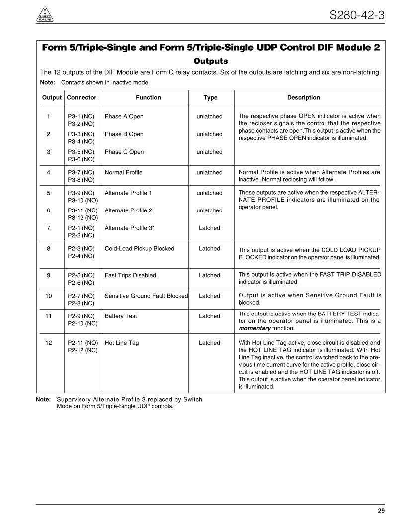
Note: Supervisory Alternate Profile 3 replaced by SwitchMode on Form 5/Triple-Single UDP controls.
S280-42-3
29
!SAFETYFOR LIFE
Form 5/Triple-Single and Form 5/Triple-Single UDP Control DIF Module 2Outputs
The 12 outputs of the DIF Module are Form C relay contacts. Six of the outputs are latching and six are non-latching.
Note: Contacts shown in inactive mode.
Output Connector Function Type Description
1 P3-1 (NC) Phase A Open unlatchedP3-2 (NO)
2 P3-3 (NC) Phase B Open unlatchedP3-4 (NO)
3 P3-5 (NC) Phase C Open unlatchedP3-6 (NO)
4 P3-7 (NC) Normal Profile unlatchedP3-8 (NO)
5 P3-9 (NC) Alternate Profile 1 unlatchedP3-10 (NO)
6 P3-11 (NC) Alternate Profile 2 unlatchedP3-12 (NO)
7 P2-1 (NO) Alternate Profile 3* LatchedP2-2 (NC)
8 P2-3 (NO) Cold-Load Pickup Blocked LatchedP2-4 (NC)
9 P2-5 (NO) Fast Trips Disabled LatchedP2-6 (NC)
10 P2-7 (NO) Sensitive Ground Fault Blocked LatchedP2-8 (NC)
11 P2-9 (NO) Battery Test LatchedP2-10 (NC)
12 P2-11 (NO) Hot Line Tag LatchedP2-12 (NC)
The respective phase OPEN indicator is active whenthe recloser signals the control that the respectivephase contacts are open.This output is active when therespective PHASE OPEN indicator is illuminated.
Normal Profile is active when Alternate Profiles areinactive. Normal reclosing will follow.
These outputs are active when the respective ALTER-NATE PROFILE indicators are illuminated on theoperator panel.
This output is active when the COLD LOAD PICKUPBLOCKED indicator on the operator panel is illuminated.
This output is active when the FAST TRIP DISABLEDindicator is illuminated.
Output is active when Sensitive Ground Fault isblocked.
This output is active when the BATTERY TEST indica-tor on the operator panel is illuminated. This is amomentary function.
With Hot Line Tag active, close circuit is disabled andthe HOT LINE TAG indicator is illuminated. With HotLine Tag inactive, the control switched back to the pre-vious time current curve for the active profile, close cir-cuit is enabled and the HOT LINE TAG indicator is off.This output is active when the operator panel indicatoris illuminated.

Sensed CurrentsPhase Current — Individual Phase Currents:
Range: 1 A to 10,000 A for 500:1 CTs
2 A to 20,000 A for 1000:1 CTs
4 A to 40,000 A for 2000:1 CTs
Accuracy:± 1 mA from 10 mA to 125 mA
0.8% from 125 mA to 1600 mA
(Control only – does not include sensortolerance.)
Ground Current — Vector Sum of Three-PhaseCurrents:
Range: 1 A to 5,000 A for 500:1 CTs
2 A to 10,000 A for 1000:1 CTs
4 A to 20,000 A for 2000:1 CTs
Accuracy: ± 3 mA from 10 mA to 125 mA
2.4% from 125 mA to 1600 mA
(Control only – does not include sensor tol-erance, but does include the phase currentsumming process.)
Sensed Source VoltagesThree-phase voltages used in voltage, power and power-factor related calculations:
Voltage measurement accuracy:
± 0.4V from 5 V to 80V
0.5% from 80 V to 135V
Kyle Form 5/Triple-Single Microprocessor-Based Recloser Control Installation and Operation Instructions
30
INPUT ACCURACY
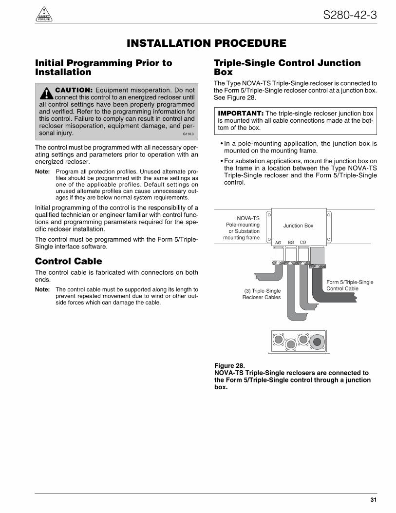
Initial Programming Prior toInstallation
The control must be programmed with all necessary oper-ating settings and parameters prior to operation with anenergized recloser.
Note: Program all protection profiles. Unused alternate pro-files should be programmed with the same settings asone of the applicable profiles. Default settings onunused alternate profiles can cause unnecessary out-ages if they are below normal system requirements.
Initial programming of the control is the responsibility of aqualified technician or engineer familiar with control func-tions and programming parameters required for the spe-cific recloser installation.
The control must be programmed with the Form 5/Triple-Single interface software.
Control CableThe control cable is fabricated with connectors on bothends.
Note: The control cable must be supported along its length toprevent repeated movement due to wind or other out-side forces which can damage the cable.
Triple-Single Control JunctionBoxThe Type NOVA-TS Triple-Single recloser is connected tothe Form 5/Triple-Single recloser control at a junction box.See Figure 28.
• In a pole-mounting application, the junction box ismounted on the mounting frame.
• For substation applications, mount the junction box onthe frame in a location between the Type NOVA-TSTriple-Single recloser and the Form 5/Triple-Singlecontrol.
S280-42-3
31
!SAFETYFOR LIFE
INSTALLATION PROCEDURE
CAUTION: Equipment misoperation. Do notconnect this control to an energized recloser until
all control settings have been properly programmedand verified. Refer to the programming information forthis control. Failure to comply can result in control andrecloser misoperation, equipment damage, and per-sonal injury. G110.3
!IMPORTANT: The triple-single recloser junction boxis mounted with all cable connections made at the bot-tom of the box.
Form 5/Triple-SingleControl Cable(3) Triple-Single
Recloser Cables
Junction BoxNOVA-TS
Pole-mountingor Substation
mounting frameAØ BØ CØ
Figure 28.NOVA-TS Triple-Single reclosers are connected tothe Form 5/Triple-Single control through a junctionbox.
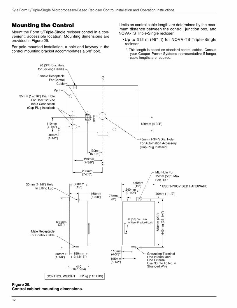
Mounting the ControlMount the Form 5/Triple-Single recloser control in a con-venient, accessible location. Mounting dimensions areprovided in Figure 29.
For pole-mounted installation, a hole and keyway in thecontrol mounting bracket accommodates a 5/8” bolt.
Limits on control cable length are determined by the max-imum distance between the control, junction box, andNOVA-TS Triple-Single recloser:
• Up to 312 m (95* ft) for NOVA-TS Triple-Singlerecloser.
* This length is based on standard control cables. Consultyour Cooper Power Systems representative if longercable lengths are required.
Kyle Form 5/Triple-Single Microprocessor-Based Recloser Control Installation and Operation Instructions
32
CONTROL WEIGHT 52 kg (115 LBS)
350mm(13-13/16")
30mm(1-1/8")
Male ReceptacleFor Control Cable
685mm(27")
Grounding TerminalOne Internal andOne ExternalUse No. 14 To No. 4Stranded Wire
110mm(4-3/8")165mm(6-1/2")
580m
m (
23")
640m
m (
25-1
/4")
40mm (1-1/2")
380mm(15")
30mm (1-1/8") HoleIn Lifting Lug 240mm
(9-1/2")76mm (3")
480mm(19")
Mtg Hole For15mm (5/8") MaxBolt Dia.*
130mm(5-1/8")
190mm(7-3/8")
120mm (4-3/4")
45mm (1-3/4") Dia. HoleFor Automation Accessory (Cap-Plug Installed)
Vent
Female ReceptacleFor Control
Cable
* USER-PROVIDED HARDWARE
CL
CL
110mm(4-1/4")
40mm(1-1/2")
200mm(7-7/8")
35mm (1-7/16") Dia. HoleFor User 120VacInput Connection
(Cap-Plug Installed)
160mm(6-3/8")
16 (5/8) Dia. Holefor User-Provided Lock
410(16-15/64)
20 (3/4) Dia. Holefor Locking Handle
Figure 29.Control cabinet mounting dimensions.
Grounding the Control
The control cabinet must be grounded. A grounding con-nector on the underside of the cabinet will accommodateNo. 14 solid through No. 4 stranded conductors.
Suggested methods for grounding the control andrecloser are shown in Figures 30, 31, and 32.
Figure 30 illustrates grounding methods for 3-wireungrounded and 4-wire multi-grounded systems with localsupply voltage transformer.
Figure 31 illustrates grounding methods for 3-wireungrounded and 4-wire multi-grounded systems withremote supply voltage transformer.
Figure 32 illustrates grounding on a 3-wire uni-groundedsystem.
For effective surge protection all control and power con-ductors for the Form 5/Triple-Single control must berouted parallel to a corresponding ground path. For exam-ple, the AC power supply for the control should be paral-lel to and equal in length to the transformer ground path.The control cable should be parallel to and routed close tothe recloser ground path.
S280-42-3
33
!SAFETYFOR LIFE
WARNING: Hazardous voltage. Recloser andcontrol must be solidly grounded. Follow all
locally approved procedures and safety practices whengrounding this equipment. Improper grounding canresult in contact with high voltage, which will causedeath or severe personal injury. G115.1
!
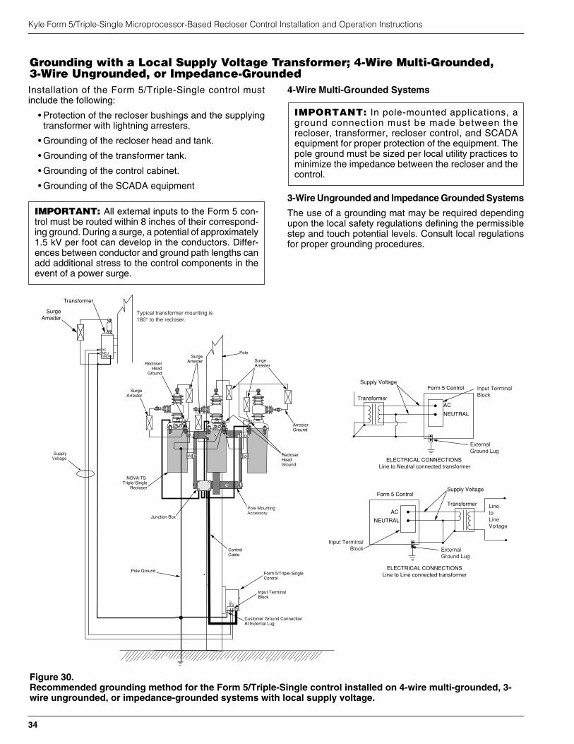
Installation of the Form 5/Triple-Single control mustinclude the following:
• Protection of the recloser bushings and the supplyingtransformer with lightning arresters.
• Grounding of the recloser head and tank.
• Grounding of the transformer tank.
• Grounding of the control cabinet.
• Grounding of the SCADA equipment
4-Wire Multi-Grounded Systems
3-Wire Ungrounded and Impedance Grounded Systems
The use of a grounding mat may be required dependingupon the local safety regulations defining the permissiblestep and touch potential levels. Consult local regulationsfor proper grounding procedures.
Kyle Form 5/Triple-Single Microprocessor-Based Recloser Control Installation and Operation Instructions
34
IMPORTANT: In pole-mounted applications, aground connection must be made between therecloser, transformer, recloser control, and SCADAequipment for proper protection of the equipment. Thepole ground must be sized per local utility practices tominimize the impedance between the recloser and thecontrol.
IMPORTANT: All external inputs to the Form 5 con-trol must be routed within 8 inches of their correspond-ing ground. During a surge, a potential of approximately1.5 kV per foot can develop in the conductors. Differ-ences between conductor and ground path lengths canadd additional stress to the control components in theevent of a power surge.
Grounding with a Local Supply Voltage Transformer; 4-Wire Multi-Grounded,3-Wire Ungrounded, or Impedance-Grounded
Pole
ControlCable
Customer Ground ConnectionAt External Lug
Pole Ground
SurgeArrester
NOVA-TS Triple-Single
Recloser
Recloser Head
Ground
CLOSED
SurgeArrester
SurgeArrester
Pole Mounting Accessory
ArresterGround
Junction Box
RecloserHeadGround
Transformer
SurgeArrester
GNDNEUAC
Typical transformer mounting is180° to the recloser.
NE
UA
C
SupplyVoltage
Input TerminalBlock
Form 5/Triple-SingleControl
AC
NEUTRAL
Form 5 ControlSupply Voltage
Transformer
ELECTRICAL CONNECTIONS Line to Neutral connected transformer
Form 5 Control
AC
NEUTRAL
Input TerminalBlock
Supply Voltage
Transformer
ELECTRICAL CONNECTIONSLine to Line connected transformer
LinetoLineVoltage
External Ground Lug
Input TerminalBlock External
Ground Lug
CLOSED
Figure 30.Recommended grounding method for the Form 5/Triple-Single control installed on 4-wire multi-grounded, 3-wire ungrounded, or impedance-grounded systems with local supply voltage.
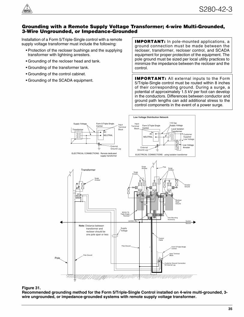
Installation of a Form 5/Triple-Single control with a remotesupply voltage transformer must include the following:
• Protection of the recloser bushings and the supplyingtransformer with lightning arresters.
• Grounding of the recloser head and tank.
• Grounding of the transformer tank.
• Grounding of the control cabinet.
• Grounding of the SCADA equipment.
S280-42-3
35
!SAFETYFOR LIFE
Pole
ControlCable
Customer Ground ConnectionAt External Lug
Pole Ground
SurgeArrester
NOVA-TS Triple-Single
Recloser
CLOSED
SurgeArrester
SurgeArrester
Pole Mounting Accessory
ArresterGround
Junction Box
RecloserHeadGround
NE
UA
C
Input TerminalBlock
Form 5/Triple-SingleControl
Pole
Transformer
ACNEUGND
AC
NEUTRAL
Form 5/Triple-SingleControl
Supply Voltage
Transformer
ELECTRICAL CONNECTIONS - Remote dedicated supply transformer
Form 5/Triple-SingleControl
AC
NEUTRAL
InputTerminalBlock
115 VacSupply Voltage
Local IsolationTransformer
ELECTRICAL CONNECTIONS - using isolation transformer
CustomerSuppliedLow Voltage
ExternalGround Lug
Low VoltageArrester
Note: Distance between transformer and recloser should be one pole span or less
ExternalGround Lug
InputTerminal
Block
Low Voltage Distribution Network
SupplyVoltage
SurgeArrester
Pole Ground
System
Neutral
CLOSED
Figure 31.Recommended grounding method for the Form 5/Triple-Single Control installed on 4-wire multi-grounded, 3-wire ungrounded, or impedance-grounded systems with remote supply voltage transformer.
IMPORTANT: All external inputs to the Form5/Triple-Single control must be routed within 8 inchesof their corresponding ground. During a surge, apotential of approximately 1.5 kV per foot can developin the conductors. Differences between conductor andground path lengths can add additional stress to thecontrol components in the event of a power surge.
IMPORTANT: In pole-mounted applications, aground connection must be made between therecloser, transformer, recloser control, and SCADAequipment for proper protection of the equipment. Thepole ground must be sized per local utility practices tominimize the impedance between the recloser and thecontrol.
Grounding with a Remote Supply Voltage Transformer; 4-wire Multi-Grounded,3-Wire Ungrounded, or Impedance-Grounded
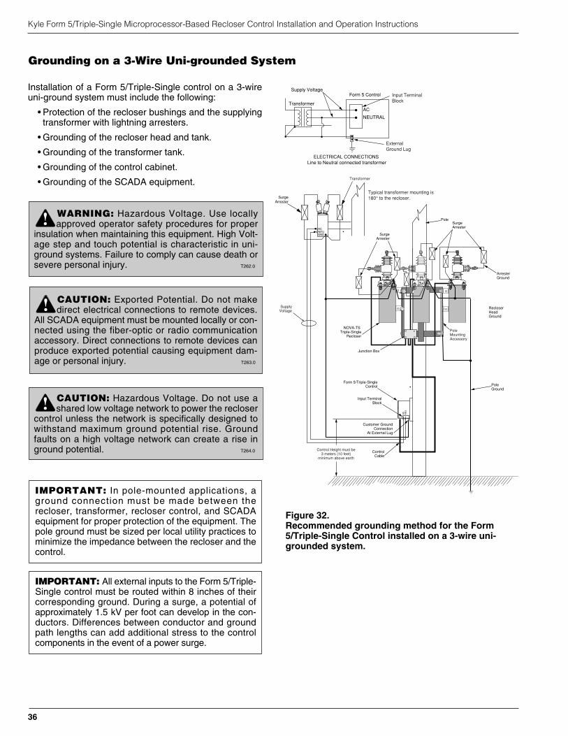
Installation of a Form 5/Triple-Single control on a 3-wireuni-ground system must include the following:
• Protection of the recloser bushings and the supplyingtransformer with lightning arresters.
• Grounding of the recloser head and tank.
• Grounding of the transformer tank.
• Grounding of the control cabinet.
• Grounding of the SCADA equipment.
Kyle Form 5/Triple-Single Microprocessor-Based Recloser Control Installation and Operation Instructions
36
Pole
ControlCable
Customer GroundConnection
At External Lug
PoleGround
NOVA-TS Triple-Single
Recloser
CLOSED
SurgeArrester
SurgeArrester
PoleMounting Accessory
ArresterGround
Junction Box
RecloserHeadGround
Typical transformer mounting is180° to the recloser.
NE
UA
C
SupplyVoltage
Input TerminalBlock
Form 5/Triple-SingleControl
AC
NEUTRAL
Form 5 ControlSupply Voltage
Transformer
ELECTRICAL CONNECTIONS Line to Neutral connected transformer
Input TerminalBlock
External Ground Lug
SurgeArrester
GNDNEUAC
Transformer
Control Height must be3 meters (10 feet)
minimum above earth
CLOSED
Figure 32.Recommended grounding method for the Form5/Triple-Single Control installed on a 3-wire uni-grounded system.
IMPORTANT: All external inputs to the Form 5/Triple-Single control must be routed within 8 inches of theircorresponding ground. During a surge, a potential ofapproximately 1.5 kV per foot can develop in the con-ductors. Differences between conductor and groundpath lengths can add additional stress to the controlcomponents in the event of a power surge.
IMPORTANT: In pole-mounted applications, aground connection must be made between therecloser, transformer, recloser control, and SCADAequipment for proper protection of the equipment. Thepole ground must be sized per local utility practices tominimize the impedance between the recloser and thecontrol.
WARNING: Hazardous Voltage. Use locallyapproved operator safety procedures for proper
insulation when maintaining this equipment. High Volt-age step and touch potential is characteristic in uni-ground systems. Failure to comply can cause death orsevere personal injury. T262.0
!
CAUTION: Exported Potential. Do not makedirect electrical connections to remote devices.
All SCADA equipment must be mounted locally or con-nected using the fiber-optic or radio communicationaccessory. Direct connections to remote devices canproduce exported potential causing equipment dam-age or personal injury. T263.0
!
CAUTION: Hazardous Voltage. Do not use ashared low voltage network to power the recloser
control unless the network is specifically designed towithstand maximum ground potential rise. Groundfaults on a high voltage network can create a rise inground potential. T264.0
!
Grounding on a 3-Wire Uni-grounded System
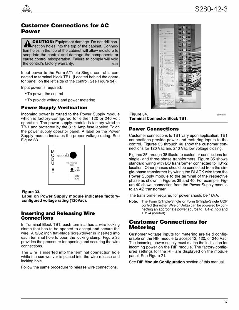
Customer Connections for ACPower
Input power to the Form 5/Triple-Single control is con-nected to terminal block TB1. (Located behind the opera-tor panel, on the left side of the control. See Figure 34).
Input power is required:
• To power the control
• To provide voltage and power metering
Power Supply VerificationIncoming power is routed to the Power Supply modulewhich is factory-configured for either 120 or 240 voltoperation. The power supply module is factory-wired toTB-1 and protected by the 3.15 Amp fuse labeled F2 onthe power supply operator panel. A label on the PowerSupply module indicates the proper voltage rating. SeeFigure 33.
Inserting and Releasing WireConnectionsIn Terminal Block TB1, each terminal has a wire lockingclamp that has to be opened to accept and secure thewire. A 3/32 inch flat-blade screwdriver is inserted intoeach terminal hole to open the locking clamp. Figure 35provides the procedure for opening and securing the wireconnections.
The wire is inserted into the terminal connection holewhile the screwdriver is placed into the wire release andlocking hole.
Follow the same procedure to release wire connections.
Power ConnectionsCustomer connections to TB1 vary upon application. TB1connections provide power and metering inputs to thecontrol. Figures 35 through 40 show the customer con-nections for 120 Vac and 240 Vac low voltage closing.
Figures 35 through 38 illustrate customer connections forsingle- and three-phase transformers. Figure 35 showsstandard wiring with BØ transformer connected to TB1-2location. Other phases should be connected from the sin-gle-phase transformer by wiring the BLACK wire from thePower Supply module to the terminal of the respectivephase as shown in Figures 39 and 40. For example, Fig-ure 40 shows connection from the Power Supply moduleto an AØ transformer.
The transformer required for power should be 1kVA.
Note: The Form 5/Triple-Single or Form 5/Triple-Single UDPcontrol (for either Wye or Delta) can be powered by con-necting an appropriate power source to TB1-2 (hot) andTB1-4 (neutral).
Customer Connections forMeteringCustomer voltage inputs for metering are field config-urable on the RIF module to accept 12, 120, or 240 Vac.The incoming power supply must match the indication forincoming power on the RIF module. The factory-config-ured settings for the RIF are displayed on the modulepanel. See Figure 21.
See RIF Module Configuration section of this manual.
S280-42-3
37
!SAFETYFOR LIFE
CAUTION: Equipment damage. Do not drill con-nection holes into the top of the cabinet. Connec-
tion holes in the top of the cabinet will allow moisture toseep into the control and damage the components orcause control misoperation. Failure to comply will voidthe control’s factory warranty. T249.0
!
Figure 34. 99003KM
Terminal Connector Block TB1.
Y
MODULE
CONFIGUREDFOR
120VAC
240VAC
F2GDC-3.15A
Figure 33.Label on Power Supply module indicates factory-configured voltage rating (120Vac).
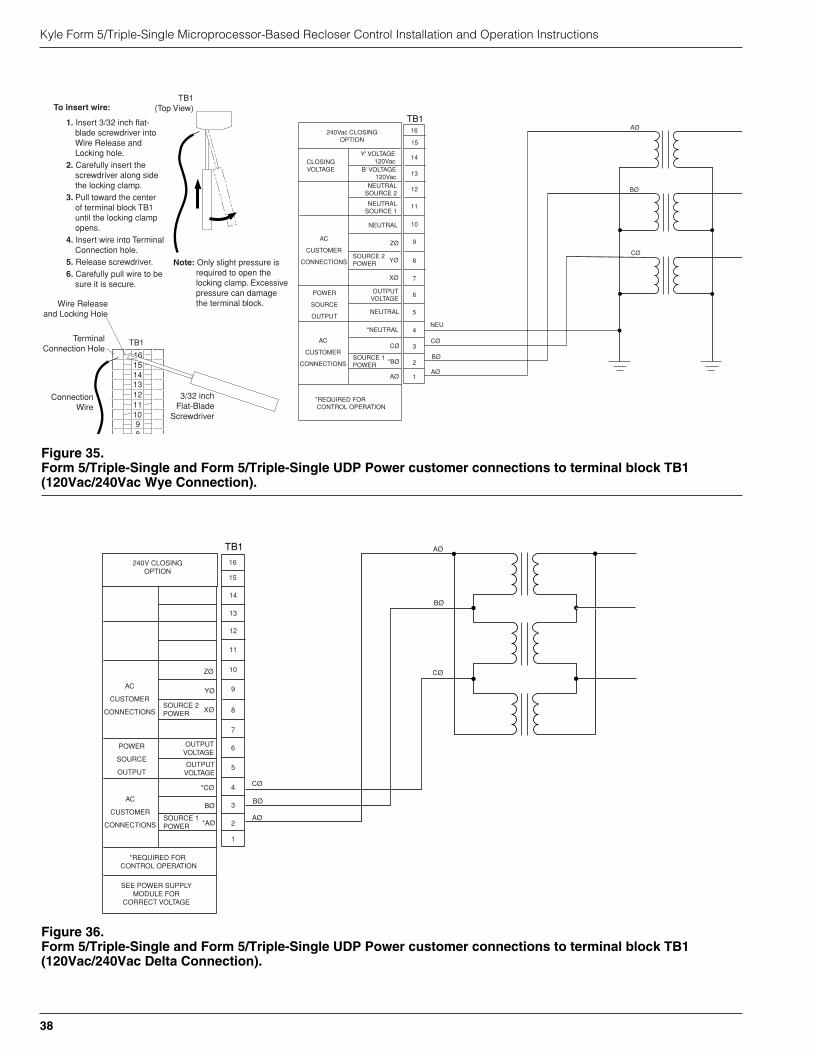
Kyle Form 5/Triple-Single Microprocessor-Based Recloser Control Installation and Operation Instructions
38
TB1
Y' VOLTAGE120Vac
B' VOLTAGE120Vac
CLOSINGVOLTAGE
NEUTRALSOURCE 2
NEUTRALSOURCE 1
AC
CUSTOMER
CONNECTIONS
NEUTRAL
ZØ
YØSOURCE 2POWER
XØ
OUTPUTVOLTAGE
NEUTRAL
*NEUTRAL
POWER
SOURCE
OUTPUT
CØ
*BØ
AØ
AC
CUSTOMER
CONNECTIONSSOURCE 1POWER
*REQUIRED FOR CONTROL OPERATION
1
2
3
4
5
6
7
8
9
10
11
12
13
14
240Vac CLOSINGOPTION
NEU
CØ
BØ
AØ
15
16 AØ
BØ
CØ
Figure 35.Form 5/Triple-Single and Form 5/Triple-Single UDP Power customer connections to terminal block TB1(120Vac/240Vac Wye Connection).
AC
CUSTOMER
CONNECTIONS
ZØ
YØ
XØSOURCE 2POWER
OUTPUTVOLTAGE
OUTPUTVOLTAGE
*CØ
POWER
SOURCE
OUTPUT
BØ
*AØ
AC
CUSTOMER
CONNECTIONSSOURCE 1POWER
*REQUIRED FOR CONTROL OPERATION
SEE POWER SUPPLYMODULE FOR
CORRECT VOLTAGE
TB1
1
2
3
4
5
6
7
8
9
10
11
12
13
14
CØ
BØ
AØ
240V CLOSINGOPTION
15
16
AØ
BØ
CØ
Figure 36.Form 5/Triple-Single and Form 5/Triple-Single UDP Power customer connections to terminal block TB1(120Vac/240Vac Delta Connection).
TB1
1615141312111098
1. Insert 3/32 inch flat-blade screwdriver into Wire Release and Locking hole.
2. Carefully insert the screwdriver along side the locking clamp.
3. Pull toward the center of terminal block TB1 until the locking clamp opens.
4. Insert wire into Terminal Connection hole.
5. Release screwdriver.6. Carefully pull wire to be
sure it is secure.
To insert wire:
TerminalConnection Hole
3/32 inchFlat-Blade
Screwdriver
TB1(Top View)
ConnectionWire
Wire Releaseand Locking Hole
Note: Only slight pressure is required to open the locking clamp. Excessive pressure can damage the terminal block.
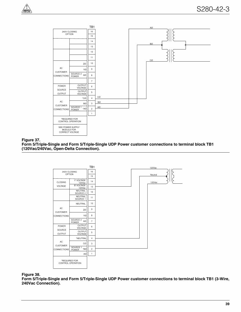
S280-42-3
39
!SAFETYFOR LIFE
AC
CUSTOMER
CONNECTIONS
ZØ
YØ
XØSOURCE 2POWER
OUTPUTVOLTAGE
OUTPUTVOLTAGE
*CØ
POWER
SOURCE
OUTPUT
BØ
*AØ
AC
CUSTOMER
CONNECTIONSSOURCE 1POWER
*REQUIRED FOR CONTROL OPERATION
SEE POWER SUPPLYMODULE FOR
CORRECT VOLTAGE
TB1
1
2
3
4
5
6
7
8
9
10
11
12
13
14
CØ
BØ
AØ
240V CLOSINGOPTION
15
16
AØ
BØ
CØ
Figure 37.Form 5/Triple-Single and Form 5/Triple-Single UDP Power customer connections to terminal block TB1(120Vac/240Vac, Open-Delta Connection).
AC
CUSTOMER
CONNECTIONS
ZØ
YØ
XØSOURCE 2POWER
OUTPUTVOLTAGE
OUTPUTVOLTAGE
CØ
POWER
SOURCE
OUTPUT
*BØ
AØ
AC
CUSTOMER
CONNECTIONSSOURCE 1POWER
*REQUIRED FOR CONTROL OPERATION
TB1
1
2
3
4
5
6
7
8
9
10
11
12
13
14
240V CLOSINGOPTION
15
16
120Vac
Neutral
120VacY' VOLTAGE
120VacB' VOLTAGE
120VacNEUTRAL
SOURCE 2
NEUTRALSOURCE 1
NEUTRAL
*NEUTRAL
CLOSING
VOLTAGE
Figure 38.Form 5/Triple-Single and Form 5/Triple-Single UDP Power customer connections to terminal block TB1 (3-Wire,240Vac Connection).

Kyle Form 5/Triple-Single Microprocessor-Based Recloser Control Installation and Operation Instructions
40
TB1
YØ VOLTAGE120Vac
BØ VOLTAGE120Vac
CLOSINGVOLTAGE
NEUTRALSOURCE 2
NEUTRALSOURCE 1
AC
CUSTOMER
CONNECTIONS
NEUTRAL
ZØ
YØSOURCE 2POWER
XØ
OUTPUTVOLTAGE
NEUTRAL
*NEUTRAL
POWER
SOURCE
OUTPUT
CØ
*BØ
AØ
AC
CUSTOMER
CONNECTIONSSOURCE 1POWER
*REQUIRED FOR CONTROL OPERATION
1
2
3
4
5
6
7
8
9
10
11
12
13
14
240Vac CLOSINGOPTION
NEU
BØ
15
16
BØ
POWER
SUPPLY
MODULE
CONFIGUREDFOR
120VAC
240VAC
P9
AUX
F2GDC-3.15A
BLK
WHT
Figure 39.Form 5/Triple-Single and Form 5/Triple-Single UDP Power and Low Voltage Closing customer connections toterminal block TB1 (Single-Phase Connection, Standard BØ Input).
TB1
Y' VOLTAGE120Vac
B' VOLTAGE120Vac
CLOSINGVOLTAGE
NEUTRALSOURCE 2
NEUTRALSOURCE 1
AC
CUSTOMER
CONNECTIONS
NEUTRAL
ZØ
YØSOURCE 2POWER
XØ
OUTPUTVOLTAGE
NEUTRAL
*NEUTRAL
POWER
SOURCE
OUTPUT
CØ
*BØ
AØ
AC
CUSTOMER
CONNECTIONSSOURCE 1POWER
*REQUIRED FOR CONTROL OPERATION
1
2
3
4
5
6
7
8
9
10
11
12
13
14
240Vac CLOSINGOPTION
NEU
15
16
AØ
POWER
SUPPLY
MODULE
CONFIGUREDFOR
120VAC
240VAC
P9
AUX
F2GDC-3.15A
BLK
WHT
AØ
Figure 40.Form 5/Triple-Single and Form 5/Triple-Single UDP Power and Low Voltage Closing customer connections toterminal block TB1 (Single-Phase Connection, AØ Input).
Before Placing the Control andthe Recloser into Service
Prior to placing the control and recloser into service, thefollowing installation procedures must be properly com-pleted and verified:
1. Control properly mounted for the installation.
2. Recloser installed according to all locally approvedstandards and practices.
3. Control and recloser properly grounded in accordancewith guidelines in this manual.
4. Control cable properly connected and supported.
5. Control battery connected and tested for properoperation.
6. AC power connected to the control. (AC power LEDindicator is ON.)
7. All control programming entered and verified byappropriate personnel.
8. Control clock set to the correct time.
9. Customer connections for remote and supervisoryoperation checked and completed in accordance withproper shielding and surge protection.
TESTING
Testing an Installed ControlThe following tests to determine initial operation of theForm 5/Triple-Single control can be performed while con-nected to an operating recloser. This is the only test per-formed on an installed, operating control. The ElectricalTesting of NOVA-TS Triple-Single Reclosers testdescribed in this section requires the Form 5/Triple-Singlecontrol to be removed from service, connected to abypassed recloser or tested at a location where the propertesting equipment is available.
1. Turn on the operator panel display by pressing theCHANGE/LAMP TEST button on the control operatorpanel.
2. Scroll through the LCD display messages asdescribed in the LCD Display Messages section ofthese instructions. See Form 5/Triple-Single ControlOperator Panel section of this manual.
Check the operational values for currents, voltages,and other metering information.
3. Check that the LED for AC power is illuminated on thecontrol operator panel. This indicates the presence ofAC power.
4. Test battery operation, using the proceduresdescribed in the Battery Test Procedure section ofthese instructions.
S280-42-3
41
!SAFETYFOR LIFE
CAUTION: Equipment misoperation. Do notconnect this control to an energized recloser
until all control settings have been properly pro-grammed and verified. Refer to the programminginformation for this control. Failure to comply canresult in control and recloser misoperation, equip-ment damage, and personal injury. G110.3
!
WARNING: Hazardous voltage. Recloser andcontrol must be solidly grounded. Follow all
locally approved procedures and safety practices whengrounding this equipment. Improper grounding canresult in contact with high voltage, which will causedeath or severe personal injury. G115.1
!
IMPORTANT: The Form 5/Triple-Single recloser con-trol can be taken out of service for testing and placedback into service without de-energizing its recloser andinterrupting the system. However, during the time thecontrol is out of service, the recloser is inoperative.
CAUTION: Equipment misoperation. Do notconnect this control to an energized recloser
until all control settings have been properly pro-grammed and verified. Refer to the programminginformation for this control. Failure to comply canresult in control and recloser misoperation, equip-ment damage, and personal injury. G110.3
!
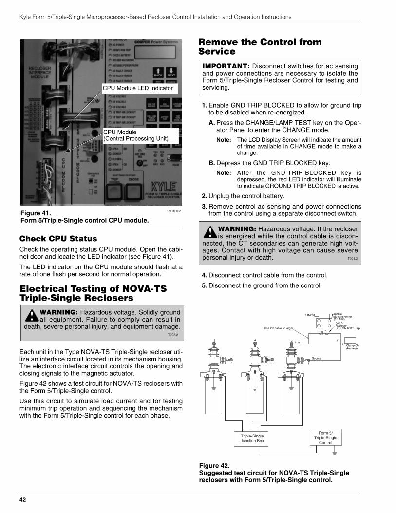
Check CPU StatusCheck the operating status CPU module. Open the cabi-net door and locate the LED indicator (see Figure 41).
The LED indicator on the CPU module should flash at arate of one flash per second for normal operation.
Electrical Testing of NOVA-TSTriple-Single Reclosers
Each unit in the Type NOVA-TS Triple-Single recloser uti-lize an interface circuit located in its mechanism housing.The electronic interface circuit controls the opening andclosing signals to the magnetic actuator.
Figure 42 shows a test circuit for NOVA-TS reclosers withthe Form 5/Triple-Single control.
Use this circuit to simulate load current and for testingminimum trip operation and sequencing the mechanismwith the Form 5/Triple-Single control for each phase.
Remove the Control fromService
1. Enable GND TRIP BLOCKED to allow for ground tripto be disabled when re-energized.
A. Press the CHANGE/LAMP TEST key on the Oper-ator Panel to enter the CHANGE mode.
Note: The LCD Display Screen will indicate the amountof time available in CHANGE mode to make achange.
B. Depress the GND TRIP BLOCKED key.
Note: After the GND TRIP BLOCKED key isdepressed, the red LED indicator will illuminateto indicate GROUND TRIP BLOCKED is active.
2. Unplug the control battery.
3. Remove control ac sensing and power connectionsfrom the control using a separate disconnect switch.
4. Disconnect control cable from the control.
5. Disconnect the ground from the control.
Kyle Form 5/Triple-Single Microprocessor-Based Recloser Control Installation and Operation Instructions
42
WARNING: Hazardous voltage. Solidly groundall equipment. Failure to comply can result in
death, severe personal injury, and equipment damage.T223.2
!
Figure 42.Suggested test circuit for NOVA-TS Triple-Singlereclosers with Form 5/Triple-Single control.
600:5RecloserBCT ON 600:5 Tap
2
115Vac VariableAutotransformer (10 Amp)
Clamp-OnAmmeter
Triple-SingleJunction Box
Use 2/0 cable or larger
1
2
3
4
5
6
Form 5/Triple-Single
Control
Source
Load
Figure 41.Form 5/Triple-Single control CPU module.
99016KM
CPU Module(Central Processing Unit)
CPU Module LED Indicator
IMPORTANT: Disconnect switches for ac sensingand power connections are necessary to isolate theForm 5/Triple-Single Recloser Control for testing andservicing.
WARNING: Hazardous voltage. If the recloseris energized while the control cable is discon-
nected, the CT secondaries can generate high volt-ages. Contact with high voltage can cause severepersonal injury or death. T204.2
!

Battery Test ProcedureThe condition of the control battery is tested by depress-ing the BATTERY TEST key on the operator panel. Noexternal current/voltage meter is necessary for testing.
The control performs a self-test every 12 hours or when initi-ated by an external command. When a battery test is initiated,the spurious charge is first drained to allow the battery voltageto equalize. A 10-ohm, 55-watt resistor is then placed acrossthe battery terminals and a voltage drop is calculated. If thedrop from the equalized voltage to the test voltage exceeds 2volts, then the CHECK BATTERY LED is illuminated.
To perform a battery test:
1. Using the NEXT and BACK keys, scroll through theLCD display to Screen 31, the Battery Monitor screen.
2. Record the NORMAL VOLTS and NORMAL CUR-RENT readings from the screen.
Note: Voltage should be between 25 to 31 volts withhigher readings at colder temperatures. Under nor-mal conditions with ac connected and the batterytrickle charging, the current should read less than20 mA. With ac connected and in bulk chargingmode, current will range from 12 to 600 mA. With acdisconnected and the battery supplying the load,current will read -180 mA to -600 mA depending onaccessories connected.
3. Momentarily, press the CHANGE/LAMP TEST key,then BATTERY TEST key.
Note: AC power can be either connected or disconnected.
4. Record the TEST VOLTS reading from the LCD andthe status of the CHECK BATTERY LED. Service thebattery if the CHECK BATTERY LED is illuminated.
Testing Procedure for UninstalledBattery
The entire process should be conducted in a clean envi-ronment, such as a repair shop.
Refer to Table 4 and follow this procedure to perform abench test on a control battery in a service shop:
1. Remove the control from service. Refer to Removethe Control from Service procedure within the Test-ing section of this manual.
2. Remove the battery from the control and carefullytransport it to a suitable service facility.
3. Measure battery voltage.
4. Apply test load and measure battery voltage after 5 sec-onds of load to determine voltage drop. Refer to Table4 for Bench Test Load Condition.
5. Remove test load.
If the battery fails the test or is at least four years old, itshould be replaced. Refer to Table 4 for battery catalog partnumbers.
Battery ChargingIf it is not possible to charge the battery with the control’sbuilt-in charger, a KA43ME7001 (120 Vac) portable benchtype battery charger is available. Refer to Service Infor-mation S280-79-14 KA43ME7001 Portable Lead AcidBattery Charger Instructions for additional information.
Use adapter KME5-325-1 to connect the two 12 volt bat-teries to the KA43ME7001 charger. Charge the batterywith a KA43ME7001 (120 Vac) portable charger.
Note: A red LED indicator on the body of the charger illumi-nates when charging.
The charger senses when the battery voltage reaches2.27 volts per cell, then the charge rate reduces to main-tain a trickle charge.
The red LED flickers to indicate the battery has reached afull charge. This process can take up to 24 hours.
S280-42-3
43
!SAFETYFOR LIFE
TABLE 4Battery Bench Testing and Replacement Information
The Form 5/Triple-Single control batteries have different dimensions; therefore, if the replacement battery ordered is a different brandthan the original battery, a kit with mounting hardware may be required to accommodate the replacement battery size.
Bench AcceptableBattery Test Load Voltage Drop Battery
Control Catalog Amp/ Condition at end of Battery ReplacementType Battery Part # Voltage Type Hour for 5 sec. Test Load Tester Kit
Form 5/ Hawker KME5-134-1 24v Lead 13 5Ω, 2v BATTERY KME5-709-17Triple- Genesis or (two Acid 55 watt or less TEST orSingle Sonnenschein KME5-134-2 12v 18 hot key on KME5-709-12high or batteries) control panel orcapacity Yuasa KME5-134-3 12 KME5-709-13
CAUTION: Recloser misoperation. The controlmust be removed from service before disconnecting
the control battery. Disconnecting the control battery from anin-service control may cause recloser misoperation (uninten-tional operation). Failure to comply can result in equipmentdamage or personal injury. T213.4
!
IMPORTANT: Never connect a single 12 volt battery tothe KA43ME7001 charger. Use adapter KME5-325-1with the battery assembly when connecting the chargerto the two 12 volt batteries.
IMPORTANT: Do not attempt to charge a lead acidbattery below 19 Vdc with the KA43ME7001 charger.Attempting to do so will damage the charger.
Return the Control to Service
Follow this procedure to return the control to service:
1. Connect cable to de-energized control and recloser.
2. Plug in the control battery.
3. Apply ac power to the control.
4. Verify that all control settings are correct.
5. Disable GND TRIP BLOCKED.
A. Press the CHANGE/LAMP TEST key on the Oper-ator Panel to enter the CHANGE mode.
Note: The LCD Display Screen will indicate the amountof time available in CHANGE mode to make achange.
B. Depress the GND TRIP BLOCKED key.
Note: After the GND TRIP BLOCKED key isdepressed, the red LED indicator will not be illu-minated indicating GROUND TRIP BLOCKED isnot active.
6. Reset the control clock after AC power has been re-applied. (Refer Setting The Control Clock in ServiceInformation S280-79-2, Form 5 Microprocessor-Based Recloser Control Programming Guide.)
Replacement KitsReplacement kits for the Kyle® Form 5/Triple-Single Con-trol are available through the factory Service Department.To order these kits, refer to the Replacement Parts pricelist for catalog numbers and pricing. Contact your CooperPower Systems representative for additional informationand ordering procedures.
Factory-Authorized ServiceCentersFactory-authorized service centers are located through-out the continental United States to provide maintenance,repair and testing services for Kyle controls and reclosers.For further information, contact your Cooper Power Sys-tems representative.
Factory Maintenance ClassesThe factory service department offers a basic testing andtroubleshooting course for the Form 5/Triple-Single Micro-processor-Based Electronic Recloser Control and NOVA-TS Recloser. This course, taught by experienced servicetechnicians, is held at the factory’s in-house training facil-ity. For additional information, contact your Cooper PowerSystems representative.
Kyle Form 5/Triple-Single Microprocessor-Based Recloser Control Installation and Operation Instructions
44 KDL6/05
1045 Hickory StreetPewaukee, WI 53072 USAwww.cooperpower.com
©2004 Cooper Power Systems or its affiliates.Kyle® is a registered trademark of Cooper Power Systems or its affiliates.
KA2048-477 Rev: 02
!SAFETYFOR LIFE
ADDITIONAL INFORMATION
CAUTION: This equipment requires routineinspection and maintenance to ensure proper
operation. If it is not maintained, it can fail to operateproperly. Improper operation can cause equipmentdamage and possible personal injury. G105.1
!CAUTION: Equipment misoperation. Do notconnect this control to an energized recloser
until all control settings have been properly pro-grammed and verified. Refer to the programminginformation for this control. Failure to comply canresult in control and recloser misoperation, equip-ment damage, and personal injury. G110.3
!