kyowa measuring instruments
TRANSCRIPT

KYOWA MEASURING INSTRUMENTS
●Strain Gages
●Load Cells
●Pressure Transducers
●Acceleration Transducers
●Torque Transducers
●Displacement Transducers
●Dynamic Strain Amplifiers
●Data Loggers
●Data Analyzers
●Instrumentation Amplifiers
& Related Instruments
●Automotive Test Equipment
●Traffic System
●Civil Engineering/
Construction Instruments
www.kyowa-ei.co.com
01
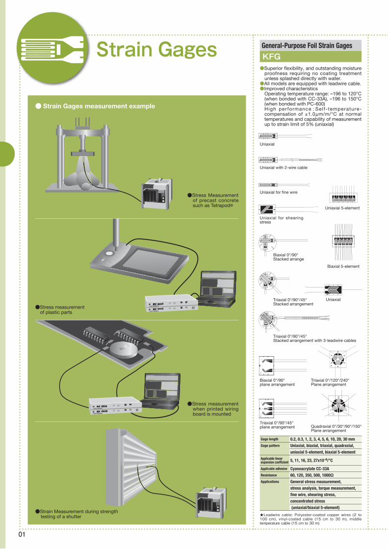
● Strain Gages measurement example
Strain Gages
★Leadwire cable: Polyester-coated copper wires (2 to 100 cm), vinyl-coated cable (15 cm to 30 m), middle temperature cable (15 cm to 30 m)
General-Purpose Foil Strain Gages
KFG●Superior flexibility, and outstanding moisture
proofness requiring no coating treatment unless splashed directly with water.
●All models are equipped with leadwire cable.●Improved characteristics
Operating temperature range: –196 to 120°C (when bonded with CC-33A), –196 to 150°C (when bonded with PC-600)High performance : Self-temperature-compensation of ±1.0μm/m/°C at normal temperatures and capability of measurement up to strain limit of 5% (uniaxial)
Gage length 0.2, 0.3, 1, 2, 3, 4, 5, 6, 10, 20, 30 mmGage pattern Uniaxial, biaxial, triaxial, quadraxial, uniaxial 5-element, biaxial 5-elementApplicable linear expansion coefficient 5, 11, 16, 23, 27x10–6/°C
Applicable adhesive Cyanoacrylate CC-33AResistance 60, 120, 350, 500, 1000ΩApplications General stress measurement, stress analysis, torque measurement, fine wire, shearing stress, concentrated stress (uniaxial/biaxial 5-element)
2
1 3
12
13
2
90
30
150
●Stress Measurement of precast concrete such as Tetrapod®
●Stress measurement of plastic parts
●Strain Measurement during strength testing of a shutter
●Stress measurement when printed wiring board is mounted
Uniaxial
Uniaxial with 2-wire cable
Uniaxial for fine wire
Uniaxial for shearing stress
Biaxial 0°/90°Stacked arrange
Triaxial 0°/90°/45°Stacked arrangement
Triaxial 0°/90°/45°Stacked arrangement with 3-leadwire cables
Biaxial 0°/90° plane arrangement
Triaxial 0°/90°/45° plane arrangement Quadraxial 0°/30°/90°/150°
Plane arrangement
Triaxial 0°/120°/240° Plane arrangement
Uniaxial
Biaxial 5-element
Uniaxial 5-element

02
★Material: Inconel 600 except for KHC-G9 made of SUS 321
★Semiconductor gages with no gage base are also available.
★Self-temperature-compensation range: –30 to120°C, applicable to thermal cycling tests
★KFP gages for plastics such as acryl are also available.
★Concrete-embedded gages (KM, KMC) are also available.
★Leadwires 1 m long
Gage length 1, 2, 3, 4, 6, 7, 9 mmGage pattern Uniaxial, biaxial 0°/90°, uniaxial 2-elementApplicable linear expansion coefficient 11, 16 × 10–6/°C(KSN)
Gage length 0.2, 1 mmGage pattern Uniaxial, biaxial 0°/90°, triaxial 0°/90°/45°
Gage length 2, 5 mmGage pattern Uniaxial, triaxial 0°/90°/45°Plane arrangementApplicable linearexpansion coefficient 1, 3, 6, 9 × 10⁻⁶/°C
Resistance 120, 350ΩOperating temperature range –55 to 200°C (adhesive: EP-34B)
Gage Length 10, 20, 30 mmGage pattern Uniaxial, biaxial 0°/90°, triaxial 0°/90°/45° (Biaxial and triaxial are available only with a gage length of 10 mm.)
Gage length 60, 70, 80, 120 mmGage pattern Uniaxial
Gage length 0.15, 0.2, 0.5, 1, 2, 5 mmGage pattern Uniaxial, triaxial 0°/90°/45°, uniaxial 5-elementApplicable linear expansion coefficient 11, 16, 23 × 10–6/°C
Resistance 120, 350Ω
Gage length 2, 5 mmGage pattern Uniaxial onlyApplicable linear expansion coefficient 11, 16, 23, 27 × 10–6/°C
Resistance 120ΩOperating temperature range –10 to 120°C
Gage length 5 mm (KHC, KHCV), 10 mm (KHCS, KHCM, KHC), 20 mm (KHC)Gage pattern 2-element temperature-compensation type except for 1-element KHCV 11 × 10–6/°C (KHCS, KHCM, KHC) 13 × 10–6/°C (KHCS, KHCM) 16 × 10–6/°C (KHCS, KHCM, KHC) KHCV: 800°C (dynamic strain) KHCS: 750°C KHCM: 650°C KHC: 550°C
Applicable linear expansion coefficient
Maximum operating temperature
Encapsulated High-Temperature Strain Gages
Encapsulated High-Temperature Strain Gages
Encapsulated High-Temperature Strain Gages
Strain Gages for Concrete
Foil Strain Gages for Composite Materials
Foil Strain Gages for Printed Boards
Foil Strain Gages with Temperature Sensor
Foil Strain Gages
Weldable Waterproof Foil Strain Gages
KHCV/KHCS/KHCM/KHC
KHCX
KHCR
KC/KFG
KFRP
KFRS
KFGT
KFR
KCW
●Designed to be spot-welded to measuring objects
●Encapsu la ted des ign enab les easy installation by spot-welding.
●Immediate measurement upon installation is possible; no curing or coating required.
●Gage length is 10 mm.●Gage resistance is 120 Ω.●Gage factor of approximately 1.5 is ensured
even at 950°C. ●Half-bridge structure ensures temperature
compensation.●Bridge adapter enables easy and error-free
connection to an amplifier.
●Encapsu la ted des ign enab les easy installation by spot-welding.
●Immediate measurement upon installation is possible; no curing or coating required.
●Gage length is 5 mm.●Gage resistance is 120 Ω.●Gage factor of approximately 1.2 or higher is
ensured even at 750°C. ●Half-bridge structure ensures temperature
compensation.●Bridge adapter enables easy and error-free
connection to an amplifier. ●Compression fitting option enables easy
wiring into a vessel, etc.
Wire Gages (KC)
Foil Gages (KFG)
●Suitable for strain measurement of composite materials such as CFRP and GFRP
●Ultra-small gage base enables bonding to mounted components and narrow space on printed boards (uniaxial: 1.2 × 1.1 mm, biaxial and triaxial: 2.5 × 2.5 mm)
●Applicable linear expansion coefficient: 13 × 10–6/°C (meeting that of printed boards)
Semiconductor Strain Gages
KSP/KSPH/KSPL/KSN●Semiconductor used for the resist ive
element ensures several 10 times higher sensitivity than foil strain gages.
●Foil strain gage and T-type thermocouple are integrated.
●Su i tab le fo r s t ra in measurement i n environment with varying or gradient temperature.
●Thermal ly- induced apparent strain is compensated with high precision.
●Polyimde base makes KFR gages usable at –196 to 150°C (adhesive: PC-600).
Waterproof Foil Strain Gages
KFW/KFWS●Usable either outdoors or underwater (100hours or more under 10MPa in water)
●Available in 2 types: Uniaxial 1-element G10●Welding type requires no coating treatment.
NEW
NEW
Applicable linearexpansion coefficient 11 × 10–6/°C
Operating temperature rang –20 to 100°CFlange size 5 × 21 mm, t = 0.1 mm
Gage length 2, 5 mmGage pattern Uniaxial, biaxial 0°/90°Stacked arrangement, triaxial 0°/90°/45°Stacked arrangement (triaxial is available only for KFW)
Applicable linear expansion coefficient 11, 16, 23 × 10–6/°C
Resistance 120, 350 Ω (KFWS: 120 Ω only)
2-E4
8-times enlarged view

03
★Boring diameter: 2 mm
★With vinyl-coated shield cable 10 m long
Gage length 1.5, 3 mmApplicable linearexpansion coefficient 11 × 10–6/°C
Operating temperature range Room temp. to 50°C
Model with terminal: Uniaxial, biaxial, triaxial; 1, 2 mm
Model for boring method: Triaxial 0°/135°/90° Plane arrangement; 1.5, 3 mm
11, 16, 23, 27 × 10–6/°C (27 is available only for boring method.)
Gage pattern and gage length
Applicable linear expansion coefficient
Gage length 2, 5 mmGage pattern Uniaxial, biaxial 0°/90°, triaxial 0°/90°/45°, bridge for bending or shearing stress measurementResistance 350Ω
Gage length 2, 5 mmGage pattern UniaxialResistance 120ΩOperating temperature range –10 to 80°C (adhesive: CC-36)
Gage length 2, 5 mmGage pattern Uniaxial, biaxial 0°/90°Plane arrangement, triaxial 0°/90°/45°Resistance 120ΩOperating temperature range –10 to 80°C(adhesive: CC-36)
Gage length 0.2, 0.5, 1, 2, 5, 30 mmGage pattern Uniaxial, triaxial 0°/90°/45°
Applicable linear 5, 11, 16, 23 × 10–6/°C expansion coefficient (5 is available only for a gage length of 30 mm)
Resistance 120, 350Ω
Gage length 5 mmOperating temperature range –50 to 350°C Applicable linear expansion coefficient 11, 16 × 10–6/°C
Gage length 2, 5 mmGage pattern Uniaxial, biaxial 0°/90°, triaxial 0°/90°/45°Applicable linear expansion coefficient 11, 16, 23 × 10–6/°C
Resistance 120, 350ΩOperating temperature range –196 to 350°C (adhesive: PI-32)
Gage length 0.2, 0.5, 1, 2, 5 mm Gage pattern Uniaxial, triaxial 0°/90°/45°Applicable linear expansion coefficient 11, 16, 23 × 10–6/°C Resistance 120ΩOperating temperature range –196 to 250°C(adhesives: PC-6, PI-32)
–55 to 200°C(adhesives: EP-34B)
Gages for Residual Stress Measurement
Gages for Bolt Axial Tension Measurement
Coating Agents
Adhesives
Gage Terminals
High-Elongation Foil Strain Gages
Ultrahigh-Elongation Foil Strain Gages
Foil Strain Gages with Protector
High-Temperature Foil Strain Gages
High-Temperature Foil Strain Gages
High-Temperature Foil Strain Gages
Low-Temperature Foil Strain Gages
KFG
KFG
KFEL
KFEM
KCH
KFU
KFH
KH
KFL
●Available in 2 types: Model equipped with a terminal for easy connection/disconnection of leadwires and model for boring method
●When it is difficult to bond a gage to the surface of a bolt for tightening stress measurement, etc., these KFG gages are embedded into the hole bored from the top head of the bolt.
●Coating agents are applied to strain gages and gage terminals to prevent them from adsorbing moisture. These agents are available in a variety of types including wax, rubber and putty.
●To ensure better measuring results, various kinds of adhesives are available for selection based on measuring objects, gage base materials and measuring conditions.
●To protect gage leads, gage terminals are applied to the connection between strain gages and leadwires. They are available in various materials and shapes.
●Enabling strain measurement in elastic to plastic region
●Enabling strain measurement for maximum elongation of approximately 10 to 15%
●Suitable for tensile tests of materials
●Enabling strain measurement in elastic to plastic region
●Enabling strain measurement for maximum elongation of 20 to 30% (room temperature)
●Suitable for tensile tests of material
●Suitable for weighing tanks and hoppers and for measuring tare weight of tracks
●Mounted to measuring objects with the adhesive and stud bolts
●Moisture and waterproofed
●Metal base enables easy bonding of the 350 Ω KH gage with the small-sized spot welder.
●Usable at a temperature as low as –269°C if bonded with PC-600 adhesive or –196°C if bonded with CC-33A or UC-26B adhesive
21
C1
1
2
D341
2
3
D35
KCH-5A-1

04
● Load Cells measurement example
Rated capacity 50 N to 2 kNNonlinearity Within ±0.5% ROHysteresis Within ±0.5% RORated output 1.4 mV/V or moreSafe overload rating 150%Dimensions & weight 50 to 200N : 10 mmφ × 4 mm high, approx. 1.5 g (excluding cable)
500N to 2KN : 16 mmφ × 7 mm high, approx. 6 g
Rated capacity 5 N to 1 kNNonlinearity Within ±1% ROHysteresis Within ±1% RORated output 0.75 to 2 mV/V (0.6 to 2 mV/V with 5N)
Safe overload rating 150%Dimensions & weight 5 to 50N : 12 mmφ × 4 mm high, approx. 1.5 g (excluding cable)
100N to 1KN : 20 mmφ × 9.5 mm high, approx. 11 g
Rated capacity 50 N to 2 kNNonlinearity Within ±0.3% ROHysteresis Within ±0.3% RORated output 1.4 mV/V or moreSafe overload rating 150%Dimensions & weight 5 to 200N : 10 mmφ × 4 mm high, approx. 1.5 g (excluding cable)
500N to 2KN : 16 mmφ × 7 mm high, approx. 6.5 g
Rated capacity 2 to 20 kNNonlinearity Within ±1% RO (within ±2% RO with 20KNSA2)
Hysteresis Within ±1% RO (within ±2% RO with 20KNSA2)
Rated output 1 mV/V or moreSafe overload rating 120%Dimensions 21 mmφ × 10 mm highweight approx. 25 g
Small-Sized Compression Load Cells
Small-Sized Compression Load Cells
Small-Sized Compression Load Cells
Small-Sized Compression Load Cells
LMR-S-SA2
LMB-A
LMA-A
LMBT-A
●Small, lightweight and low cost
●Ultra-small, lightweight and low cost
●Ultra-small, lightweight and low cost
●Ultra-small,for high temperature (100°C)
Load CellsLMA-A-5 to 50N
LMBT-A-50 to 200N
LMA-A-100N to 1KN
LMBT-A-500N to 2KN
LMB-A-50N to 200N
LMB-A-500N to 2KN
LMR-S-20KNSA2
●Load measurement of plate bearing test
●Weight control of Hopper Tank
●Load control of Press machine
●6 component force measurement of an artificial leg or robot with built-in load cells
05
Rated capacity 500 N to 50 kNNonlinearity Within ±0.03% RO (within ±0.05% RO with 500KA or larger)
Hysteresis Within ±0.03% RO (within ±0.05% RO with 500KA or larger)
Rated output 3 mV/V ±0.2%Safe overload rating 150%weight approx. 300 g ~ approx. 4.4 kg
Rated capacity 500 N to 200 kNNonlinearity Within ±0.5% ROHysteresis Within ±0.5% RORated output 1.5 mV/V ±0.2%Safe overload rating 200%Critical overload 500%weight approx. 2.3 kg ~ approx. 45 kg
Rated capacity 500 N to 200 kNNonlinearity Within ±0.5% RO
Hysteresis Within ±0.5% RO Rated output 1.5 mV/V ±0.2%Safe overload rating 200%weight approx. 1.5 kg ~ approx. 8.5 kg
Rated capacity 100, 200 kNNonlinearity Within ±0.02% RO Hysteresis Within ±0.02% RO Rated outpu 2 mV/V ±0.1%Safe overload rating 200%Dimensions 156 mmφ × 90 mm high to 176 mmφ × 110 mm highweight approx. 12 kg ~ approx. 17 kg
Rated capacity 5 to 200 kNNonlinearity Within ±0.2% RO (within ±0.5% RO with 200KN)
Hysteresis Within ±0.2% RO (within ±0.5% RO with 200KN)
Rated output 2 mV/V ±0.5%Safe overload rating 150%Dimensions 78 mmφ × 25 mm high to 118 mmφ × 50 mm highweight approx. 900 g ~ approx. 4.1 kg
Rated capacity 2, 5 MNNonlinearity Within ±0.5% ROHysteresis Within ±0.2% RORated output 2 mV/V ±1%Safe overload rating 150%Dimensions 210 mmφ × 267 mm high ~ 340 mmφ × 267 mm highweight approx. 49 kg ~ approx. 65 kg
High-Temp. Compression Load Cells
High/Low-Temp. Tension Load Cells
High-Accuracy Tension Load Cells
General-Purpose Compression Load Cells
Thin Compression Load Cells
High-Accuracy Compression Load Cells
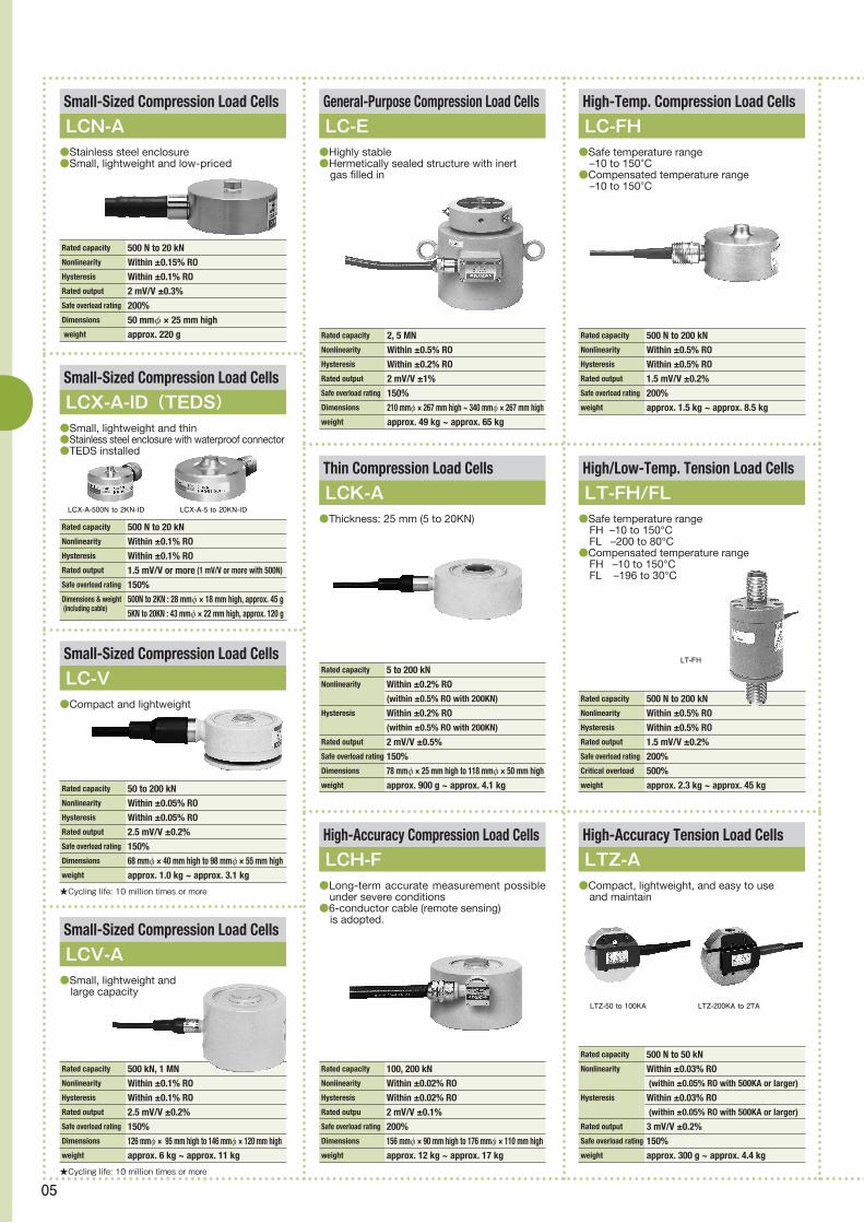
LC-FH
LT-FH/FL
LTZ-A
LCK-A
LCH-F
LC-E●Safe temperature range –10 to 150°C●Compensated temperature range –10 to 150°C
●Safe temperature range FH –10 to 150°C FL –200 to 80°C●Compensated temperature range FH –10 to 150°C FL –196 to 30°C
●Compact, lightweight, and easy to use and maintain
●Highly stable●Hermetically sealed structure with inert gas filled in
●Thickness: 25 mm (5 to 20KN)
●Long-term accurate measurement possible under severe conditions
●6-conductor cable (remote sensing) is adopted.
LTZ-50 to 100KA LTZ-200KA to 2TA
LT-FH
★Cycling life: 10 million times or more
Rated capacity 50 to 200 kNNonlinearity Within ±0.05% ROHysteresis Within ±0.05% RORated output 2.5 mV/V ±0.2%Safe overload rating 150%Dimensions 68 mmφ × 40 mm high to 98 mmφ × 55 mm highweight approx. 1.0 kg ~ approx. 3.1 kg
Rated capacity 500 N to 20 kNNonlinearity Within ±0.1% ROHysteresis Within ±0.1% RORated output 1.5 mV/V or more (1 mV/V or more with 500N)
Safe overload rating 150%Dimensions & weight 500N to 2KN : 28 mmφ × 18 mm high, approx. 45 g (including cable)
5KN to 20KN : 43 mmφ × 22 mm high, approx. 120 g
Rated capacity 500 N to 20 kNNonlinearity Within ±0.15% ROHysteresis Within ±0.1% RORated output 2 mV/V ±0.3%Safe overload rating 200%Dimensions 50 mmφ × 25 mm high weight approx. 220 g
Small-Sized Compression Load Cells
Small-Sized Compression Load Cells
Small-Sized Compression Load Cells
LCX-A-ID(TEDS)
LC-V
LCN-A●Stainless steel enclosure●Small, lightweight and low-priced
●Small, lightweight and thin●Stainless steel enclosure with waterproof connector●TEDS installed
●Compact and lightweight
LCX-A-500N to 2KN-ID LCX-A-5 to 20KN-ID
★Cycling life: 10 million times or more
Rated capacity 500 kN, 1 MNNonlinearity Within ±0.1% ROHysteresis Within ±0.1% RORated output 2.5 mV/V ±0.2%Safe overload rating 150%Dimensions 126 mmφ × 95 mm high to 146 mmφ × 120 mm highweight approx. 6 kg ~ approx. 11 kg
Small-Sized Compression Load Cells
LCV-A●Small, lightweight and large capacity

06
★Order production goods
Rated capacity ±500 N to ±200 kN Nonlinearity Within ±0.2% RO
Hysteresis Within ±0.1% RO
Rated output ±2 mV/V ±0.2%Safe overload rating 150%weight approx. 3.9 kg ~ approx. 22.5 kg
Tension/Compression Load Cells
LU-E
Rated capacity ±50 to ±200 N
Nonlinearity Within ±0.3% RO Hysteresis Within ±0.2% RO Rated output ±1.5 mV/V ±0.5%Safe overload rating 120%Weight approx. 2.3 kg
Rated capacity ±500 N to ±200 kN Nonlinearity Within ±0.02% ROHysteresis Within ±0.02% RORated output ±2 mV/V ±0.1%Safe overload rating 150%Weight approx. 2.1 kg ~ approx. 38 kg
Small-Capacity Tension/Compression Load Cells
High-Accuracy Tension/Compression Load Cells
LU-A
LUH-F
●Small capacity●High accuracy
●Excellent zero-float characteristic (50 to 500KF)●6-conductor cable (remote sensing) is adopted.
★Interference: ±3% RO
Rated capacity 10 N to ±500 N with all force
components Fx, Fy and FzNonlinearity Within ±0.5% RO Hysteresis Within ±0.5% RO
Rated output Approx. ±0.5 mV/V Safe overload rating 150%Weight approx. 600 g ~ approx. 1.6 kg
Rated capacity LVS : 50 mN to 20 N
LTS : 500 mN to 20 NNonlinearity Within ±0.5% RO
Hysteresis Within ±0.5% RO
Rated output 1.5 mV/V or more (1.2 mV/V with 5 and 10GA)
Safe overload rating 120%Weight approx. 50 g
Rated capacity 50 N to 20 kN
Nonlinearity Within ±0.03% RO (within ±0.05% RO with 100KB or larger)
Hysteresis Within ±0.03% RO (within ±0.05% RO with 100KB or larger)
Rated output 2 mV/V ±0.3%Safe overload rating 150%Weight approx. 530 g ~ approx. 3.2 kg
Rated capacity ±5 kN to ±2 MN Nonlinearity Within ±0.1% RO (within ±0.2% RO with 500KN or larger)
Hysteresis: Within ±0.1% RO (within ±0.2% RO with 500KN or larger)
Rated output ±2 mV/V ±1 % (±10% with 5KN ~ 20KN)
Safe overload rating 150%Weight approx. 900 g ~ approx. 245 kg
3-Component Force TransducerTension/Compression Load Cells
Beam-Shape Load Cells
Load Cells for Minute Load Measurement
LSM-B-SA1LUK-A
LUB-B
LVS-A/LTS-A
●Compact, lightweight, and easy to handle
●Thin designe
●Compact, lightweight and low cost●Metal bellows adopted
●Enable highly accurate measurement of minute load.
●2 types are available : LVS senses load in vertical direction tothe
mounting surface and LTS senses load in horizontal direction to the mounting suface.
LVS-A
★For TEDS, see "About TEDS" on page 07.
Rated capacity ±50 N to ±200 N Nonlinearity Within ±0.15% ROHysteresis Within ±0.15% RORated output ±0.9 mV/V or moreSafe overload rating 150%weight approx. 50 g
Small-Sized Tension/Compression Load Cells
LUX-B-ID(TEDS)●Minimal thermal effects on output.●Suitable for measuring and controlling loads
applied to small-scale presses and press-fitting devices.
NEW
Rated capacity ±50 N to ±2 kN
Nonlinearity Within ±0.5% RO
Hysteresis Within ±0.5% RO
Rated output ±0.5 mV/V or more (Approx. ±0.4 mV/V with 50NSA1)
Safe overload rating 150%Weight approx. 80 g
Small-Sized Tension/Compression Load Cells
LUR-A-SA1●Compact, lightweight, 28 mm in diameter

07
Rated capacity 5 to 100 kN
Nonlinearity Within ±0.05% RO
Hysteresis Within ±0.05% RO Rated output 2 mV/V ±0.1% Safe overload rating 150%
Rated capacity 500 N to 3 kN Nonlinearity Within ±0.05% RO
Hysteresis Within ±0.05% RO Rated output 2 mV/V ±0.2% Safe overload rating 150%
Rated capacity 1 to 5 MNNonlinearity Within ±1% ROHysteresis Within ±1% RORated output 1 mV/V or moreSafe overload rating 150%
Rated capacity 10 to 300 kNNonlinearity Within ±1% ROHysteresis Within ±1% RORated output approx. 1 mV/VSafe overload rating 150%
Washer-Type Load Cells
Washer-Type Load Cells
Stainless Steel Load Cells
Thin Load Cells “Multiforce Sensor”
LCW-C-SA3
LCW-D-S/E-S
LCTS-B
LCTA-A
●Models of the same capacities are available with different diameters.
●Thin design makes them suitable for industrial applications.
●Hermetically-sealed structure with inert gas filled in
●Heat-and oil-ewsistant cable●High reliability
●For weighing of tanks and hoppers●Thin, top and bottom plates integrated, and
steady brace provided
●Endure lateral load and highly accurate.●Rubber attachment enables use with the top
and bottom fixed.
LCW-D-S
LCW-E-S
Rated capacity 100 to 300 kN
Nonlinearity Within ±0.03% RO
Hysteresis Within ±0.03% RO
Rated output 2 mV/V ±0.2%
Safe overload rating 150%
Rated capacity 10 to 100 kN
Nonlinearity Within ±0.05% RO (±0.1% RO with 100KN)
Hysteresis Within ±0.05% RO (±0.1% RO with 100KN) Rated output 2 mV/V ±0.2%
Safe overload rating 150%
Rated capacity 5 to 50 kN Nonlinearity Within ±0.03% RO
Hysteresis Within ±0.03% RO
Rated output 1.5 mV/V ±0.2% Safe overload rating 150%
Thin Load Cells “Multiforce Sensor”
Thin Load Cells “Multiforce Sensor”
Thin Load Cells “Multiforce Sensor”
LCTB-A
LCTE-A
LCTD-A
Rated capacity Refer to the table belowNonlinearity Within ±0.5% ROHysteresis Within ±0.5% RORated output Approx. ±1500 mV with no-load output at the centerSafe overload rating 150%Dimensions 66 mmφ × 40 mm highWeight Refer to the table below
Rated capacity Refer to the table belowNonlinearity Within ±0.5% ROHysteresis Within ±0.5% RORated output Refer to the table belowSafe overload rating 150%Dimensions 66 mmφ × 40 mm highWeight Refer to the table below
Model
Model
LFM-A-1KN
LFM-A-3KN
LFX-A-1KN
LFX-A-3KN
FX : ±1000N
FY : ±1000N
FZ : ±1000N
MX : ±50N・m
MY : ±50N・m
MZ : ±25N・m
FX : ±3000N
FY : ±3000N
FZ : ±3000N
MX : ±100N・m
MY : ±100N・m
MZ : ±50N・m
FX : ±1000N
FY : ±1000N
FZ : ±1000N
MX : ±40N・m
MY : ±40N・m
MZ : ±25N・m
FX : ±3000N
FY : ±3000N
FZ : ±3000N
MX : ±100N・m
MY : ±100N・m
MZ : ±50N・m
FX : ±1.5mV/V or more
FY : ±1.5mV/V or more
FZ : ±1.8mV/V or more
MX : ±4.0mV/V or more
MY : ±4.0mV/V or more
MZ : ±2.4mV/V or more
FX : ±1.6mV/V or more
FY : ±1.6mV/V or more
FZ : ±1.6mV/V or more
MX : ±2.4mV/V or more
MY : ±2.4mV/V or more
MZ : ±1.6mV/V or more
160g
360g
210g
420g
Approx. ±1500 mV with no-load output at the center
Rated capacity
Rated capacity Rated output
Rated output Weight, approx.
Weight, approx.
Compact 6-Component Force Transducers
Compact 6-Component Force Transducers with Built-in Amplifier
LFM-A
LFX-A
About TEDS (Transducer Electronic Data Sheet)To enable amplifier to correctly measure signals of transducers, amplifiers should be adjusted based on transducer's calibration data. Conventionally, such adjustment has been made manually by engineer. TEDS-installed transducers let TEDS-compatiable amplifiers read the data to ensure automatic adjustment upon connect ion, thereby shortening adjustment and prevent ing erroneous setting.

08
●Pressure Transducers measurement example
Pressure Transducers
★Materials: SUS metal finish (mainframe), SUS 630 (liquid-contacting part)
★Materials: Aluminum, alumite treated (mainframe), SUS 630 (liquid-contacting part)
★Material: Metal finish
Rated capacity 500 kPa to 50 MPaNonlinearity Within ±0.3% RO (within ±0.5% RO with 5 to 20KH)
Hysteresis Within ±0.2% RO Rated output 2 mV/V or more
(1.5 mV/V or more with 5KH)
Safe overload rating 150%Mounting screw G3/8, maleWeight approx. 120 g
Rated capacity 1 to 50 MPaNonlinearity Within ±0.2% RO (within ±0.3% RO with 20KA,
within ±0.4% RO with 10KA)
Hysteresis Within ±0.2% RO Rated output 2 mV/V ±0.5% Safe overload rating 150%Mounting screw G3/8, maleWeight approx. 120 g
Rated capacity 1 to 50 MPaNonlinearity Within ±0.3% RO
(within ±0.5% RO with 2MPa or smaller)
Hysteresis Within ±0.2% RO
(within ±0.5% RO with 2MPa or smaller)
Rated output 2 mV/V ±20%
(within ±30% with 2MPa or smaller)
Safe overload rating 150%Mounting screw G1/8, maleWeight approx. 20 g
Small-Sized Pressure Transducers
Small-Sized Pressure Transducers
Small-Sized Pressure Transducers
PGL-A
PGS-A
PGM-H
●Semiflush type for measurement of highly viscous medium
●Compact, lightweight, and highly durable; vibration acceleration 490.3 m/s2, impact acceleration 4903 m/s2
●Semiflush type for measurement of highly viscous medium
PGL-A-A
●oil pressure control of construction machinery
●Pressure measurement in tight space such as inside a pipe
●Refr igerant pressure monitor ing of on air condit ioner
●Used for touch-sensors by mourt ing pressure transducers to a robot

09
★Material: SUS 630 (liquid-contacting part)
★Materials: SUS metal finish (mainframe), SUS 630 (liquid-contacting part)
★Materials: SUS metal finish (mainframe), SUS 630 (liquid-contacting part)
★Materials: SUS metal finish (mainframe), SUS 304 (liquid-contacting part)
★Materials: SUS metal finish (mainframe), SUS 630 (liquid-contacting part)
★Materials: Aluminum, alumite treated(mainframe), ZDC, chrome-plated (mainframe) with 10KU or larger, SUS 630 (liquid-contacting part)
★Material: Metal finish, connector type
★Materials: C1720 (liquid-contacting part), SUS 303 (screw)
Rated capacity 200 kPaabs ~ 2 MPaabsNonlinearity Within ±0.1% RO Hysteresis Within ±0.1% RO Rated output 2 mV/V or moreSafe overload rating 150%Mounting screw 7/16-20UNFWeight approx. 130 g
Rated capacity 1 ~ 20 MPaNonlinearity Within ±0.1% ROHysteresis Within ±0.1% RORated output 1.5 mV/V ±5%Safe overload rating 300%Mounting screw G3/8, maleWeight approx. 400 g
Rated capacity 5 ~ 50 MPaNonlinearity Within ±0.5% ROHysteresis Within ±0.5% RORated output 1.5 mV/V ±20%Safe overload rating 150%Mounting screw G1/8, maleWeight approx. 150 g (the cable is contained)
Rated capacity 20 ~ 100 kPaNonlinearity Within ±0.5% ROHysteresis Within ±0.3% RORated output PGM-02KG: 0.75 mV/V or more PGM-05KG: 1.25 mV/V or more PGM-1KG: 1.4 mV/V or moreSafe overload rating 150%Mounting screw M14 × 1, maleWeight approx. 40 g (the cable is contained)
Rated capacity 100, 200 MPaNonlinearity Within ±0.2% RO Hysteresis Within ±0.2% RO Rated output 1.5 mV/V ±0.5% Safe overload rating 150%Mounting screw G1/2, maleWeight approx. 220 g
Rated capacity 200 kPa ~ 50 MPaNonlinearity Within ±0.2% RO (within ±0.3% RO with 2 to 10KU)
Hysteresis Within ±0.2% RO (within ±0.3% RO with 2 to 10KU)
Rated output 2 mV/V ±0.5% (±1% with 2 to 10KU) Safe overload rating 150%Mounting screw G3/8, maleWeight approx. 300 g (approx. 500 g with 2.5KN)
Rated capacity 1 ~ 50 MPaNonlinearity Within ±0.3% RO (within ±0.5% RO with 2MPa or smaller)
Hysteresis Within ±0.2% RO (within ±0.5% RO with 2MPa or smaller)
Rated output 2 mV/V ±20% (within 30% with 2MPa or smaller)
Safe overload rating 150%Mounting screw G1/8, maleWeight approx. 20 g
Rated capacity 200 kPa ~ 1 MPaNonlinearity Within ±1.5% ROHysteresis Within ±1.5% RORated output PGM-200kPa: 0.6 mV/V or more PGM-500kPa, 1MPa:1mV/V or more ±20%Safe overload rating 150%Mounting screw G1/8, maleWeight approx. 140 g (the cable is contained)
Small-Capacity Pressure Transducers
Small-Sized Stainless Steel Pressure Transducers
High-Pressure-Resistant Pressure Transducers
Absolute Pressure Transducers
Small-Sized Pressure Transducers
Small-Sized High/Low Temp. Pressure Transducers
Pressure Transducers
High Pressure Transducers
PGM-G
PGM-D
PGR-A
PAB-A
PGMC-A
PHL-A
PG-U
PG-H
●Communicating tube incorporated in the cable for back Pressure compensation
●Small pressure sensing surface, flush diaphragm type
●Usable at high temperatures up to100°C●Withstanding high pressures●Highly accurate
●Measurement from absolute pressure Zero absolute pressure (vacuum) possible
●Flush diaphragm type for measurement of highly viscous medium
●Safe temperature range: –196 to 210°C
●Pressure sensing part diameter as small as 5.5 mm●Flush diaphragm type
★Materials: SUS metal finish (mainframe), SUS 630 (liquid-contacting part) (SUS 630 and SUS 304 with 10 and 20KE)
Rated capacity 1 ~ 50 MPa
Nonlinearity Within ±1% RO Hysteresis Within ±1% RO Rated output 1 mV/V or more
(1.4 mV/V or more with 500KE)
Safe overload rating 150%Mounting screw G3/8, maleWeight approx. 200 g (the cable is contained)
Small-Sized Pressure Transducers
PGM-E●Flush diaphragm type
PHL-A-B

10
★Type C: Flat, type D: Conical; Type D is available only for PSM series.
★Materials: SUS metal finish (mainframe), SUS 630 (liquid-contacting part)
★Materials: SUS metal finish (mainframe), SUS 630 (liquid-contacting part)
Rated capacity 50 kPa to 7 MPaNonlinearity Within ±1% ROHysteresis Within ±1% RORated output 0.25 to 1 mV/VSafe overload rating 150%Weight approx. 0.15 to 0.5 g
Rated capacity 2 to 20 MPaNonlinearity Within ±0.3% RO (within ±0.4% RO with 2MPSA2)
Hysteresis Within ±0.2% RORated output 2 mV/VSafe overload rating 150%Mounting screw R1/8 maleWeight approx. 50 g
Rated capacity 1 to 50 MPaNonlinearity Within ±0.4% ROHysteresis Within ±0.4% RORated output 2.2 mV/V ±15%Safe overload rating 120%Mounting screw G3/8, maleWeight approx. 530 g (the cable is contained)
Rated capacity 200 kPaabs to 20 MPaabsNonlinearity Within ±0.2% ROHysteresis Within ±0.2% RORated output 1.5 mV/V or moreSafe overload rating 150%Mounting screw G3/8, maleWeight approx. 150 g
Highly Reliable Sputter Gage Pressure Transducers
High/Low-Temperature Pressure Transducers
Small-Sized High-Temp. Pressure Transducers
Miniature Pressure Transducers
PHS-A
PHB-A
PHF-S-SA2
PSS/PS/PSM●Safe temperature range: -196 to 230°C●Long-term stable measurement at 200°C●Absolute pressure measurement possible●Excellent high-temperature characteristics
●Safe temperature range: –196 to 210°C
●Safe temperature range: –40 to 170°C●Compact and lightweight
●Thin, small in diameter, lightweight, intended for distributed pressure measurement
●Bondable with adhesive
★Materials: SUS metal finish (mainframe), SUS 630 (liquid-contacting part)
★Materials: SUS metal finish (mainframe), SUS 630 (liquid-contacting part)
★Materials: SUS metal finish (mainframe), SUS 630 (liquid-contacting part)
★Materials: SUS metal finish (mainframe), SUS 630 (liquid-contacting part)
Rated capacity 500 kPa to 50 MPaNonlinearity Within ±0.3% RO
(within 0.5% RO with 5K ~ 20K)
Hysteresis Within ±0.3% RO
(within 0.5% RO with 5K ~ 20K)
Rated output PVL-A,C : 1 to 5V PVL-B,D : 0 to 5V PAL : 4 to 20mASafe overload rating 150%Mounting screw G3/8, maleWeight approx. 110 g
Rated capacity 500 kPa to 50 MPaNonlinearity Within ±0.2% ROHysteresis Within ±0.2% RORated output PAV-R,U : 0 to 5V PAA-R,U : 4 to 20mASafe overload rating 200%Mounting screw G3/8, maleWeight approx. 200 to 260 g
Rated capacity 200 kPa to 1 MPaNonlinearity Within ±0.1% RO (within ±0.05% RO(Typica) to 30 to 70% of each rated capacity,
The transducer is usually used in that range)
Hysteresis Within ±0.2% RORated output 4 to 20 mV/VSafe overload rating 150%Mounting screw G3/8, maleWeight approx. 270 g
Rated capacity 2 to 20 MPaNonlinearity Within ±0.5% ROHysteresis Within ±0.5% RORated output 0.6 mV/V or moreSafe overload rating 150%Mounting screw G1/8, maleWeight approx. 115 g (the cable is contained)
Rated capacity 1 to 7 kPaNonlinearity Within ±0.5% RO
(within 0.7% RO with 25GA)
Hysteresis Within ±0.3% RORated output PDS-10GA : ±7 to 23 mV PDS-25 to 70GA : ±13 to 23 mV PDV-A: ±5 VSafe overload rating PDS/PDV-10GA: 600% PDS/PDV-25 to 70GA : 300%Weight PDS : approx. 40 g PDV : approx. 100 g
Output Pressure Transmitters
Micro Differential Pressure Transducers
Flush Diaphragm Type High-Temperature Pressure Transducers
Highly Stable Current-Output Pressure Transducers
Output Pressure Transmitters
PVL/PAL
PDS-A/PDV-A
PHC-B
PAG-A
PAV-R/U,PAA-R/U●Compact, lightweight, quick response, high accuracy and high sensitivity
●Safe temperature range: –30 to 240°C
●Highly reliable●Highly stable●High resolution●Noise resistant
●Highly Resistant against Noise during Transmission
PDS-A PDV-A
PVL-A,B
R type U type

11
Rated capacity ±9.807 to 196.1 m/s2
Nonlinearity Within ±1% RO
Hysteresis Within ±1% RO
Rated output 0.5 mV/V or moreSafe overload rating 300%Frequency response range DC to (40 to 250) HzWeight approx. 15 g (GA), 25 g (GB)
Small-Capacity Acceleration Transducers
AS-GA,GB●Compact and lightweight design gives minimal effect to vibration mode.
●Acceleration Transducers measurement example
AccelerationTransducers
AS-GA
AS-GB
●Drop impact tests of fuel cell container and Lithium-ion battery
●Vibration tests on goods daring truck transportation
●Vibration tests on railway vehicle and truck
●Vibration tests on various structures such as piers

12
★Hydraulic resistance : 490.3 kPa
Rated capacity ±9.807 to 196.1 m/s2
Nonlinearity Within ±1% ROHysteresis Within ±1% RORated output 0.5 mV/V or moreSafe overload rating 300%Frequency response range DC to (40 to 250) HzWeight approx. 40 g
Rated capacity ±98.07 to 9807 m/s2
Nonlinearity Within ±1% ROHysteresis Within ±1% RORated output 0.5 mV/V or more (TA) 0.5 mV/V ±20% (TB) (±25% with 10TB) Safe overload rating 300% (each axis)Frequency response range DC to (1.2 to 5) kHz (TA) DC to (350 Hz to 1 kHz) (TB)Weight approx. 45 g (TA), 95 g (TB)
Rated capacity ±9.807 to 196.1 m/s2
Nonlinearity Within ±1% ROHysteresis Within ±1% RORated output 0.5 mV/V or moreSafe overload rating 1000% (with stopper)Frequency response range DC to (40 to 250) HzWeight approx. 110 g
Rated capacity ±980.7 to 9807 m/s2 (HA) ±98.07 to 490.3 m/s2 (HB)Nonlinearity Within ±1% RO Hysteresis Within ±1% RO Rated output 0.5 mV/V ±20% (±25% with 10HB)Safe overload rating 300%Frequency response range DC to (2 to 7) kHz (HA), DC to (500 Hz to 1.5 kHz) (HB)Weight approx. 6.5 g (HA), 13 g (HB)
Rated capacity ±980.7 to 9807 m/s2 (A) ±98.07 to 490.3 m/s2 (B)Nonlinearity Within ±1% RO
Hysteresis Within ±1% RO
Rated output 0.5 mV/V or more (A) 0.5 mV/V ±20 % (±25% with 10B) (B)Safe overload rating 300%Frequency response range DC to (1.2 to 5) kHz (A) DC to (300 Hz to 1 kHz) (B)Weight approx. 6.5 g (A), 13 g (B)
Quick Response Acceleration Transducers
Small-Sized Triaxial Acceleration Transducers
Triaxial Acceleration Transducers
Waterproof Acceleration TransducersSmall-Sized Acceleration Transducers
AS-HA,HB
AS-TG
AS-TA,TB
ASW-AAS-A,B●Simultaneous measurement of acceleration in X, Y and Z directions.
●Usable under water and soil●Compact and lightweight●Cycling life: 10 million times
AS-B
AS-A
AS-HA
AS-HB
AS-TA
AS-TB

13
★Mating amplifier : DPM dynamic strain amplifier (carrier: 5 kHz)★TPN-AB with no installation feet and TPN-CB with installation feet
Rated capacity 100 to 500 N・mNonlinearity Within ±0.2% ROHysteresis Within ±0.2% RORated output 1.2 mV/V or moreSafe overload rating 150%MAX. speed 5000 to 12000 rpm
Rated capacity TPS-A-10NM: ±10 N・m TPS-A-50NM: ±50 N・mNonlinearity Within ±0.3% ROHysteresis Within ±0.3% RORated output ±5 ± 0.2 V(load resistance 5 kΩ or more)
Safe overload rating TPS-A-10NM:150%, TPS-A-50NM:120%MAX. speed 5000 rpm
Rated capacity 0.2 to 5 N・mNonlinearity Within ±0.2% ROHysteresis Within ±0.2% RORated output 0.75 to 1.5 mV/VSafe overload rating 150% (stopper operates at 150%.)
Operating speed 3000 to 15000 rpm
★TP-D with no installation feet and TP-E with installation feet
Rated capacity 0.2 to 2 N・mNonlinearity Within ±1% ROHysteresis Within ±1% RORated output 0.75 to 1.5 mV/VSafe overload rating 120%MAX. speed 4000 rpm
Torque Transducers
TPS-A
Small-Sized Torque Transducers
TP-D/E●For small torque measurement
High-Speed Torque Transducers
TP-M●For small torque measurement●Equipped with overload prevention stopper
●Non-contact design facilitates maintenance.
Rotary Transformer Torque Transducers
TPN-AB/CB●Non-contact design facilitates maintenance.
● Torque Transducers measurement example
TorqueTransducers
★TP-AB with no installation feet and TP-CB with installation feet
Rated capacity 100 N・m to 5 kN・mNonlinearity Within ±0.2% ROHysteresis Within ±0.2% RORated output 1.5 mV/V ±0.2% (±0.5% with 5 kN・m)Safe overload rating 120%MAX. speed 2500 to 9000 rpm
Torque Transducers
TP-AB/CB●Bending or thrust of the shaft causes minimal adverse effect, thereby enabling highly accurate measurement. TP-CB
TPN-CB
TP-E
NEW
●Torque measurement and control of a stir machine when food is stirred
●Torque measurement of wind power generator and dynamo
●Torque evaluation of motors

14
●Displacement Transducers measurement example
DisplacementTransducers
Rated capacity 5 to 100 mmNonlinearity Within ±0.1% ROHysteresis Within ±0.1% RORated output 5 mV/V ±0.1%Measuring force: approx. 1.5 to 4 N
Displacement Transducers
DTH-A●Compact, lightweight, highly accurate and high output level
Rated capacity 200 mmNonlinearity Within ±0.3% ROHysteresis Within ±0.3% RORated output 5 mV/V ±0.3%Measuring force approx. 5.9 N
Displacement Transducer
DTJ-A-200●Direct-reading scale provided
Rated capacity 50, 100 mmNonlinearity Within ±0.5% ROHysteresis Within ±0.5% RORated output 1.5 mV/V ±20%Measuring force approx. 4.4 N
Displacement Transducers
DT-A●Direct-reading scale provided
Rated capacity 10 to 50 mmNonlinearity Within ±0.5% ROHysteresis Within ±0.5% RORated output 1.5 mV/V or moreMeasuring force approx. 1.47 to 1.77 NSafe overload rating 100%
Dial Gage Displacement Transducers
DT-D●Direct-reading dial gage provided●Easy installation and maintenance
★Flexible steady point type is available.
★Mating amplifier: DPM dynamic strain amplifier (carrier: 5 kHz)
Rated capacity 500 to 5000 mmNonlinearity Within ±0.3% ROHysteresis Within ±0.3% RORated output 5 mV/V ±0.3%Measuring force 0.98 to 1.67 NSafe overload rating 120%
Potentiometer Displacement Transducers
DTP-D-S●For large displacement measurement ●Compact, lightweight and high output level
DTP-D-2KS DTP-D-500S DTP-D-5KS
Rated capacity ±5 to 500 mmNonlinearity Within ±0.5% ROHysteresis Within ±0.5% RORated output approx. ±2 mV/V
Inductance Displacement Transducers
DLT-AS/BS●Less abrasion and small measuring force
●Displacement measurement of antiseismic rubber used for seismical ly isolated structure in vibration test
●Deflection measurement in auto body strength test
●Deflection or displacement measurement on strength test of scaffolding frames
●Displacement measurement of plate bearing test

15
● Dynamic Strain Amplifiers measurement example
Dynamic Strain Amplifiers
Number of measuring 1channels
(multi-channel configuration possible
by combining multiple units)
Models and frequency DPM-911A: DC to 2.5 kHzresponse ranges
DPM-912A: DC to 5 kHzOutput OUTPUT A: ±10 V (load resistance 5 kΩ or more) OUTPUT B: ±10 V (load resistance 5 kΩ or more)Low-pass filter Second order Butterworth Cutoff frequency: 6 steps of 10, 30, 100, 300, 1k [Hz] and FLAT Cutoff accuracy: –3 ± 1 dB Attenuation: –12 ± 1 dB/oct. (except when the low-pass filter of DPM-911A is set to 1 kHz) Power supply AC LINE (approx. 10 VA/100 VAC), 10.5 to 15 VDC (approx. 0.6 A/12 VDC) Dimensions 49(W) × 128.5(H) × 262.5(D) mm (excluding protrusions) Panel cut dimensions: 50(W) × 113(H) mmWeight approx. 1.2 kg
Strain Amplifiers
DPM-911A/912A●Working hours can be greatly shortened by
easy setting.●Sensitivity (measuring range) is set in
combination of strain level and output voltage settings.
●High voltage output of ±10 V and high SN ratio are ensured.
●Vertical bar meter is easy to see.●Sensitivity of TEDS-installed transducer is
automatically registered. ●Overinput is alarmed by flickering 4½-digit
output voltage indicator.●Unbalanced capacitive components are
automatically canceled by the CST method.
NEW
●Motors or assist- motor fatigue test
●Vibration measurement house of solar panels or with solar panels attached
●Gait analysis of disabled people
16
●Unit Bases MCD-8A/16A
●Speifications Common to All Conditioner Cards
●Dynamic Strain Amplifier Cards DPM-71A/72A
●Signal Conditioner Card CDV-71A
●Thermocouple Card CTA-71A
●F-V Converter Card CFV-71A
●Charge Amplifier Card CCA-71A
●Monitor Card DPE-71A
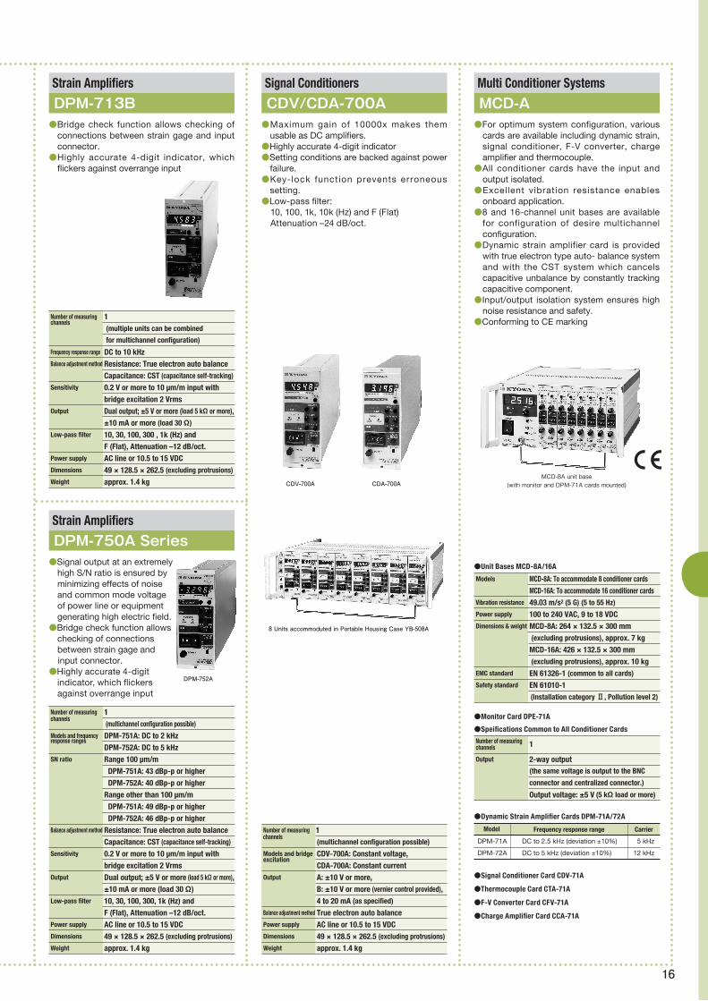
Models MCD-8A: To accommodate 8 conditioner cards MCD-16A: To accommodate 16 conditioner cardsVibration resistance 49.03 m/s2 (5 G) (5 to 55 Hz)
Power supply 100 to 240 VAC, 9 to 18 VDCDimensions & weight MCD-8A: 264 × 132.5 × 300 mm (excluding protrusions), approx. 7 kg MCD-16A: 426 × 132.5 × 300 mm
(excluding protrusions), approx. 10 kgEMC standard EN 61326-1 (common to all cards)
Safety standard EN 61010-1 (Installation category Ⅱ, Pollution level 2)
Number of measuring channels 1
Output 2-way output (the same voltage is output to the BNC
connector and centralized connector.)
Output voltage: ±5 V (5 kΩ load or more)
Number of measuring 1 channels
(multichannel configuration possible)
Models and bridge CDV-700A: Constant voltage, excitation
CDA-700A: Constant currentOutput A: ±10 V or more, B: ±10 V or more (vernier control provided), 4 to 20 mA (as specified)
Balance adjustment method True electron auto balancePower supply AC line or 10.5 to 15 VDC Dimensions 49 × 128.5 × 262.5 (excluding protrusions)
Weight approx. 1.4 kg
Number of measuring 1channels
(multichannel configuration possible)
Models and frequency DPM-751A: DC to 2 kHzresponse ranges
DPM-752A: DC to 5 kHzSN ratio Range 100 μm/m DPM-751A: 43 dBp-p or higher DPM-752A: 40 dBp-p or higher Range other than 100 μm/m DPM-751A: 49 dBp-p or higher DPM-752A: 46 dBp-p or higher Balance adjustment method Resistance: True electron auto balance Capacitance: CST (capacitance self-tracking)
Sensitivity 0.2 V or more to 10 μm/m input with bridge excitation 2 VrmsOutput Dual output; ±5 V or more (load 5 kΩ or more), ±10 mA or more (load 30 Ω)Low-pass filter 10, 30, 100, 300, 1k (Hz) and F (Flat), Attenuation –12 dB/oct. Power supply AC line or 10.5 to 15 VDCDimensions 49 × 128.5 × 262.5 (excluding protrusions)
Weight approx. 1.4 kg
Number of measuring 1channels
(multiple units can be combined
for multichannel configuration)
Frequency response range DC to 10 kHzBalance adjustment method Resistance: True electron auto balance Capacitance: CST (capacitance self-tracking)
Sensitivity 0.2 V or more to 10 μm/m input with bridge excitation 2 VrmsOutput Dual output; ±5 V or more (load 5 kΩ or more), ±10 mA or more (load 30 Ω)
Low-pass filter 10, 30, 100, 300 , 1k (Hz) and F (Flat), Attenuation –12 dB/oct. Power supply AC line or 10.5 to 15 VDC Dimensions 49 × 128.5 × 262.5 (excluding protrusions)
Weight approx. 1.4 kg
Multi Conditioner SystemsSignal ConditionersStrain Amplifiers
Strain Amplifiers
MCD-ACDV/CDA-700ADPM-713B
DPM-750A Series
●For optimum system configuration, various cards are available including dynamic strain, signal conditioner, F-V converter, charge amplifier and thermocouple.
●All conditioner cards have the input and output isolated.
●Excellent vibration resistance enables onboard application.
●8 and 16-channel unit bases are available for configuration of desire multichannel configuration.
●Dynamic strain amplifier card is provided with true electron type auto- balance system and with the CST system which cancels capacitive unbalance by constantly tracking capacitive component.
●Input/output isolation system ensures high noise resistance and safety.
●Conforming to CE marking
●Maximum gain of 10000x makes them usable as DC amplifiers.
●Highly accurate 4-digit indicator●Setting conditions are backed against power
failure.●Key-lock function prevents erroneous
setting.●Low-pass filter: 10, 100, 1k, 10k (Hz) and F (Flat) Attenuation –24 dB/oct.
●Bridge check function allows checking of connections between strain gage and input connector.
●Highly accurate 4-digit indicator, which flickers against overrange input
●Signal output at an extremely high S/N ratio is ensured by minimizing effects of noise and common mode voltage of power line or equipment generating high electric field.
●Bridge check function allows checking of connections between strain gage and
input connector.●Highly accurate 4-digit
indicator, which flickers against overrange input
MCD-8A unit base(with monitor and DPM-71A cards mounted)
DPM-752A
Model
DPM-71A
DPM-72A
5 kHz
12 kHz
DC to 2.5 kHz (deviation ±10%)
DC to 5 kHz (deviation ±10%)
Frequency response range Carrier
CDV-700A CDA-700A
8 Units accommoduted in Portable Housing Case YB-508A

17
● Data Loggers measurement example
Data Loggers
●Static measurement of solar panel
●Point load test of concrete pillar
●load test of glider wing
NTB-101A-350
NTB-100A-120
Network Terminal Boxes
NTB-100A (For TEDS)●Decentralized arrangement to wide places is
possible via a single wire.●These compact and lightweight bridge boxes
provide digital output.●One AC adapter enables coupl ing of
maximum 8 units.●Easy software enables quick measurement.
NEW
Number of Measuring Channels
4
Scanning Speed Approx. 0.5 seconds per channel for 0 to ±30000 μm/m Approx. 1 second per channel for 0 to ±300000 μm/mBridge Excitation Approx. 2 VDC for constant-voltage bridge excitation Approx. 5.6 mA for constant-current bridge excitation
(with bridge resistance 350 Ω)
Measuring Range 0 to ±300000 μm/m with constant-voltage bridge excitation 0 to ±30000 μm/m with constant-current bridge excitation –30.0 to 70.0°C with civil engineering transducers having temperature measuring functionResolution 1 μm/m for 0 to ±30000 μm/m, 10 μm/m for 0 to ±300000 μm/m, 0.1°CAccuracy ±(0.05% rdg. + 2 μm/m) for 0 to ±30000 μm/m ±(0.10% rdg. + 20 μm/m) for 0 to ±300000 μm/m ±0.5°COperating Temperature Range –10 to 50°C
Operating HumidityRange 20 to 85% RH (noncondensing)
Power Supply 11 to 16 VDCDimensions & Weight One-touch lock type 150(W) × 28(H) × 55(D) mm (excluding protrusions), approx. 310 g Screw soldering type 150(W) × 28(H) × 110(D) mm (excluding protrusions), approx. 650 g

18
Number of Measuring Channels 1
Sampling Frequency Approx. 2 Hz with strain input in a range of 0 to ±30000 μm/m Approx. 1 Hz with strain input exceeding ±30000 μm/m Approx. 1 Hz with civil engineering transducer with temperature measuring functionMeasuring Mode Relative mode (each value is obtained by deducting the initial unbalance)
Calculation Function Enables multiplication of each measurement by coefficient.Bridge Excitation Constant voltage: 2 VDC, Constant current: 5.6 mA (bridge resistance 350 Ω)
Measuring Range Strain : 0 to ±300000 μm/m with constant-voltage bridge excitation 0 to ±20000 μm/m with constant-current bridge excitation Temp.: –30° to 70°C with civil engineering transducer with temperature measuring functionCheck Function Insulation resistance measurement: 2 MΩ to 100 MΩ Resistance measurement: 0 to 20 kΩInterval Measurement Selectable interval: 1 minute to 99 hours 59 minutes in 1-minute steps Starting date/time: Year/month/day, hour:minuteDisplay Monochrome LCD, 128 × 64 dotsOperating Temperature –10° to 50°CHumidity Range 20 to 85% RH (noncondensing)
Power Supply AA size alkaline dry cell (2 pieces)Dimensions & Weight 108.4 × 188 × 41 mm, approx. 450 g
Handy Data Logger
SME-30A/31A/100A/101A (For TEDS)●Measurement data is saved in SD card.●Bridge circuit is built in, enabling direct connection of strain gage. ●Measuring range is ±300000 μm/m.●Network Terminal Box enables multi-channel measurement with the
SME-100A.
Data Loggers
UCAM-60B/65B (For TEDS)The UCAM-60B data logger is an all-in-one instrument developed in full pursuit of easy handling in the field. The instrument is provided with all functions required for measurement in the field, including easy-to-use keys, bright readable display and printer for immediately confirming measured results. The UCAM-65B is an online version wholly controlled by the PC.Both models can measure up to 30 channels of data with the mainframe only, while external scanners enable measurement in up to 1000 channels. Measured results are stored in internal memory and are saved in a flash ATA card if inserted in the PC card slot for offline data transfer to the PC. In addition, the UCAM-60B and UCAM-65B are provided with Ethernet and RS-232C ports which enable the PC to not only control these data loggers through the control software UCS-60B but also process data for rosette analysis, etc. in the field by directly receiving data.
UCAM-60B●Fluorescent display tube ensures easy observation in the field.●Built-in thermal printer enables immediate confirmation of measured
results.●Control software UCS-60B (optional for UCAM-60B) can place the
UCAM-60B under the control of the PC connected through Ethernet or RS-232C port.
UCAM-65B●With the UCAM-65B, measuring conditions, etc. are set from the PC
and measured results are transferred to the PC.●Can be used for interval measurement as a stand-alone unit with no PC
connected.
Common to UCAM-60B and UCAM-65B●Can connect TEDS-compatible sensors (dedicated scanning unit USS-
61B/62B/63B)●Can measure up to 20000 μm/m with a resolution of 0.1 μm/m.●Scanning at 50 ms/channel●High-speed scanning at 20 ms/channel is possible.●DC-operated version is available for operation where no AC outlet is
available.●Configuration
Mainframe : UCAM-60B,UCAM-65BDedicated scanners mounted to mainframe: USS-61B (TEDS-compatible) USS-62B (with NDIS connectors,TEDS-compatible) USS-62B M6 (with clamp-style terminal board and NDIS connectors) USS-63B (TEDS-compatible, with lightning arrester) Note : A dedicated scanner is provided with 10 channels and up to 3 units can be mounted to the mainframe.External scanners USB-70 series (USI-67A scanner interface required) USB-51A/51AT (USI-65A scanner interface required) USB-20A/50A (USI-65A scanner interface required) USB-50D (USI-65A scanner interface required)Scanner interfaces USI-67A for USB-70 series USI-65A for USB-20/50/51 seriesExternal input/output unit UIO-60AControl software UCS-60B
SME-100A SME-30A
NEW
★For TEDS, see "About TEDS" on page 07.

19
CPU Pentium 4 2 GHz or higher or the equivalentOS MS-Windows 98/98SE/Me/2000/XP/VistaMemory 2 GB or moreHard disk 10 MB or more (excluding data)
Control Software
UCS-60BThe software enhances the performance of the data logger by letting the PC present measured results in graphic and numeric formats as well as perform data analysis.●Controls UCAM-60A/B, 65A/B, 20PC, and 500A/B.●Enables presentation of numeric list on the PC.●Enables presentation of maximum 50 graphs at a time on the PC with
20-CH data/window.●Arithmetic operation, statistic operation and rosette analysis●Reading and storing of measuring and calculating condition files
Number of measuring Max. 30 with dedicated scannerschannels
Max. 1000 with external scanners Max. 1000 with internal scanners plus external scanners Scanning speed 50 ms/channel (standard mode) (USS-61B/62B/63B only) 280 ms/channel (high-resolution mode) (Can be set for every channel.)
20 ms/channel (high-speed mode) (Available for USS-61, 62, and 63B only)
PC card slot Conforms to PCMCIA Ver. 4.2. Accepts commercially available flash ATA card.Interface RS-232C, LAN (10BASE-T/100BASE-TX)
Operating temperature 0 to 50°Chumidity range 20 to 85% RH (noncondensing)
Power supply 85 to 264 VAC, 50/60 Hz (AC version)
10 to 16 VDC (DC version)
Dimensions UCAM-60B: 360 × 88 × 400 mm (excluding protrusions)
UCAM-65B: 327 × 88 × 365 mm (excluding protrusions)
Weight approx. 8 kg (60B), 5 kg (65B)
Notes : 1. With USS-63B mounted 2. Use either of the scanner interfaces for connection to external scanners. 3. 120 to 1000 Ω with high-resolution mode
Data Loggers UCAM-60B/65B●Sensors and connectable scanners
Sensor
Scanner External scanner
General purpose
USB-70B-10/20 USB-70B-30
Civil engineeringInternal scanner
Not required*1
-67A -67A
Strain gages & strain gage transducers 1-gage method 120 Ω 240 Ω 350 Ω 1-gage true dummy method 120 Ω 240 Ω 2-gage method, 60 to 1000 Ω Active-dummy method Active-active method Common dummy method 4-gage method, 60 to 1000 Ω*3
Opposite side active method Full-bridge methodCivil engineering transducers 4-gage method, 120 Ω Constant-current excitation 4-gage method, 350 Ω Constant-current excitation With temp. measuring functionVoltage output sensors (DC)Temperature Thermocouple K(CA) T (CC) E (CRC) J (IC) R Platinum resistance thermometer sensor Pt100 (new JIS) JPt100 (old JIS)Potentiometer sensorsBuilt-in lightning arresterScanner interface (USI-)*2
● Measured Data Monitor Windows
● Data Reproduce Window
● Condition Setting Windows
Bar Graph Window
Numeric Window
X-Y Graph
Measuring Conditions
TEDS Information
System Management
Data Filing Conditions

20
●2 models are available: PCD-300B for strain measurement and PCD-320A for voltage measurement.
●Connected to the PC via USB interface●One unit provides 4 channels and 4 units
enable 16-channel measurement.●Optional synchronous cable enables
simultaneous sampling with 4 units.●Synchronous connection enables simultaneous
measurement of strain and voltage.●The dynamic data acquisition software DCS-
100A which operates on Windows 2000/XP/Vista is provided standard for PCD-300B, while the control software PCD-30A which operates on Windows 98/98SE/Me/ 2000/XP, for PCD-320A.
●The DCS-100A supports both PCD-300B and PCD-320A.
●Low cost●Compact and lightweight●Optional analysis software DAS-100A or NI
DIAdem enables data analysis on the PC.
Specifications common to PCD-300B and PCD-320A
●Number of measuring channels: 4 (up to 4 units can be connected in cascade for 16-channel measurement.)
●Interface: USB 1.1●Operating temperature/humidity range: 0 to
40∞C, 20 to 85% RH (noncondensing)●Power supply: 100 to 240 VAC (AC adapter
provided standard)
Sensor Interfaces
PCD-300 SeriesThe PCD-300 ser ies sensor inter faces make the existing PC a versatile measuring instrument. The PCD-300B enables the PC to perform stress measurement through the use of strain gages and force, pressure, accel-eration and displacement measurement through the use of strain gage transducers. The PCD-320A enables the PC to measure voltage signals. The sensor interfaces are connected to the PC via USB interface.Connect st ra in gages and stra in gage transducers or voltage output type sensors to the rear input terminals of the sensor interface and start the accessory dynamic data acquisition software DCS-100A. Then, the PC operates as a measuring instrument. Once sensors are connected, interactive operation on the PC enables the operator to obtain measured data in proper engineering units. One sensor interface provides 4 channels and up to 4 units can be connected in cascade to extend to a 16-channel system suitable for small-scale measurement. Needless to say, the PCD-300B can be combined with the PCD-320A for simultaneous measurement of strain and voltage signals. Thus, the PCD-300 series can effectively be utilized as measuring tools in every scene including simple experiments and sophisticated measurement.
●Solar panel impact and damage measurements
●Oil pressure measurement of automatic transmission
●Drop impact test of lithium-ion battery
● Data Analyzers measurement example
DataAnalyzers

21
PCD-300BPC is not provided.
Applicable sensors Strain gages, strain gage transducersApplicable gage resistance 1 or 2-gage method: 120Ω 4-gage method: 120 Ω to 1 kΩInput adapters UI-10A (with NDIS connectors for strain gage transducers, TEDS-compatible)
UI-11A (clamp-style terminal board for strain gages, TEDS-compatible)
UI-15A (lever-equipped terminal board for strain gages)
UI-16A (quick-fitting lock-style terminal board for strain gages)
Bridge excitation 2 VAC rms, carrier: 1 kHz sine waveBalance adjustment range Resistance: ±2% (±10000 μm/m) or more Capacitance: 5000 pF or moreBalance adjustment method Resistance: True electron auto-balance system Capacitance: CST system (automatic tracking)
Nonlinearity Within ±0.1% FSGage factor 2.00 fixedRange 8 steps of 200, 500, 1000, 2000, 5000, 10000. 20000 μm/m and OFF Accuracy Within ±0.5% FSFrequency band DC to 200 Hz, deviation ±10%Low-pass filter Second order Butterworth (PCD-300B-F only) Cutoff frequency: 10, 30, 100 Hz and Flat Amplitude ratio at cutoff point: –(3 ± 1) dB Attenuation: –(12 ± 1) dB/oct.A-D converter Resolution max. 24 bitsSampling frequency 1 Hz to 10 kHz (simultaneous sampling)
Current consumption 0.7A or less (12 VDC)
Dimensions 265.2 × 26.7 × 215 mm (excluding protrusions)
Weight approx. 1.1 kg with UI-10A mounted (excluding accessory AC adapter)
★For TEDS, see "About TEDS" on page 07.
PCD-300B
PCD-330B-F
Applicable Sensors Type of output of voltage of voltage output type converter conditionerInput form Unbalanced inputRange 7 steps of 1, 2, 5, 10, 20, 50v and offAccuracy Within 0.2%Frequency Response Range DC ~ 1 kHz deviation -3 + 1dBHigh-pass Filter 2 steps of 0.2Hz and offLow-pass Filter Second order ButterworthCutoff frequency 5 steps of 10,30,100,300Hz and Flat Amplitude ratio at cutoff point −(3±1)dBAttenuation −(12±1)dB/oct.Zero Stability Within ±0.03% FS/8h,within±0.003% FS/°CSensitivity Stability Within ±0.1%/8h,within±0.02%/°C
Strain gauges Strain gauge transducers The voltage output type converter is connected, The warp and pressure, the acceleration, and displacement, etc. are requested in each engineering only by setting it at least.
●Standard equipment Low-pass filter
Warp measurement mode specificationEach specification is the same as the following (PCD-300B, PCD-300B-F)
PCD-330B-F
Voltage measurement mode specification
Applicable sensors Voltage output sensorsInput mode UnbalancedInput resistance 1 MΩ or moreCoupling DC/AC switchableRange 7 steps of 1, 2, 5, 10, 20, 50 V and OFFFrequency response range DC coupling: DC to 1 kHz AC coupling: 0.2 Hz to 1 kHz Deviation: within +1/–3 dBLow-pass filter Transmission characteristics: 2nd order Butterworth Cutoff frequency: 5 steps of 10, 30, 100, 300 Hz and FLAT Amplitude ratio at cutoff point: –(3 ± 1) dB/oct. Attenuation: –(12 ± 1) dB/oct.A-D converter Resolution12-bit, successive approximation, simultaneous samplingSampling frequency 1 Hz to 5 kHzExternal trigger signal No-voltage conact, open collector, 5 V CMOS level, number of points: 1Measuring input terminals BNC connectors Input/output not isolated Max. allowable input voltage: 30 VAC or 60 VDC Max. rated grounding voltage: 30 VAC or 60 VDCDimensions 265.2 × 24.7 × 215 mm (excluding protrusions)
Weight approx. 750 g (excluding accessory AC adapter)
Safety standard EN61010-1, installation category Ⅱ , pollution degree 2EMC standard EN61326-1, class A instrument
PCD-320A
For strain gauges transducers having the cable terminated with NDIS connector Plug UI-10A For strain gauges and strain gauge transducer having the cable bared at the tip UI-11A (clamp-style terminal block) UI-15A (clamp-style terminal block with operating levers) UI-16A (one-touch lock type clamp-style terminal block) Voltage measurement exclusive use UI-30A (BNC connector Plug)
Input Adapter Options
★A-Dconverter:ach specification is the same as the following.(PCD-300B,PCD-300B-F) Sampling frequency TEDS function, Interface, Externals size, Weight
Control Software
PCD-30AThe control software PCD-30A enables the PC to control the sensor interfaces of PCD-320A. Using the software, the PC sets measuring conditions and performs data acquisition, graph display and file conversion to CSV format on MS-Windows 2000/XP/Vista. The software is supplied in CD-R and for use, it is installed in the hard disk of the PC.
Input Adapter UI-10A(TEDS-compatible)with NDIS connectors
Input Adapter UI-15AClamp-style terminal blockwith operating levers
Input Adapter UI-16AClamp-style terminal blockwih quick-fitting locks
Input Adapter UI-11A(TEDS-compatible)Clamp-style terminal block
Strain gage
Strain gagetransducer
Voltageinput
PC
USB cable
Dynamic Data Acquisition Software DCS-100A
(compatible with Windows 2000/XP/Vista)
PCD-300B
PCD-320A
Synchronous Cable N-90

22
CPU Pentium Ⅲ 700 MHz or higher OS Windows 2000/XPMemory 256 MB or more Hard disk Blank space 10 MB or more (except for data)
Control Software
EDS-40AEnables the PC to set, save and read channel, measuring and recording conditions as well as monitor measuring data and perform data collection, data coupling, graph dispay, file conversion and environmental setting.
Typical recording time with 128-MB CF card (standard accessory)
Samplingequency
100kHz
50kHz
20kHz
10kHz
5kHz
2kHz
1kHz
500kHz
200kHz
100kHz
50kHz
20kHz
10kHz
5kHz
2kHz
1kHz
8.0 minutes
16 minutes
40 minutes
80 minutes
160 minutes
6.6 hours
13 hours
26 hours
2.7 days
5.5 days
11 days
27 days
55 days
111 days
277 days
555 days
8.0 minutes
20 minutes
40 minutes
80 minutes
3.5 hours
6.6 hours
13 hours
33 hours
2.7 days
5.5 days
13 days
27 days
55 days
138 days
277 days
13 minutes
26 minutes
53 minutes
133 minutes
4.4 hours
8.8 hours
22 hours
44 hours
3.7 days
9.2 days
18 days
37 days
92 days
185 days
10 minutes
20 minutes
40 minutes
100 minutes
3.3 hours
6.6 hours
16 hours
33 hours
2.7 days
6.9 days
13 days
27 days
69 days
138 days
Number of measuring channels
1 2 3 4
Compact Recorder
EDS-400AThe EDS-400A is a compact 4-channel recorder equipped with signal conditioners and high-speed 16-bit resolution A-D converters, enabling high-speed digital recording of dynamic strain and voltage phenomena.Desired measuring and recording conditions are set to the recorder by communicating with the PC through LAN or by inserting a compact flash memory card in which the conditions are written beforehand.Measured data is directly written in the compact flash memory card, while it is possible to monitor the waveform on the PC during data acquisition in progress.Acquired data is transferred to the PC either on line via LAN or off line via the compact flash memory card.The accessory software enables the PC to display the waveform of the collected data, while the optional DAS-100A or NI DIAdem data analysis software enables data analysis in various modes. ●Compact and lightweight design requires less space.●4-channel measurement possible with a single unit●Up to 8 units can be connected for 32-channel measurement.●Maximum sampling frequency of 100 kHz (1-channel measurement) ensures high-speed recording.●Simultaneous sampling of 4 channels is possible at 20 kHz.●Suitable as an onboard data logger●LAN interface provided●Analog filters are built in.
Number of measuringchannels 4
Applicable sensors Strain gages (4-gage method),Strain gage transducers,Voltage output sensorsApplicable bridge resistance 120 to 1000 Ω (4-gage method)Gage factor 2.00 fixedBridge excitation 2 VDCVoltage measuring range ±20 VFrequency response range DC to 20 kHzResolution of A-D conversion 16 bitsSampling method Simultaneous sampling of all channelsSamping frequency 1 Hz to 100 kHz (16 steps)LAN interface 10BASE-T/100BASE-TXMonitoring Waveform, bar graph and numeric data can be monitored on the PC connected via LAN.Data storage Compact flash memory card (128 MB to 1 GB)Synchronized operation Possible by connecting up to 8 units in cascade with dedicated synchronous cables.Operating temperature 0 to 50 °Chumidity range 20 to 90%RH (noncondensing)Vibration resistance 49.03 m/s2 (5 G) (5 to 55 Hz) (when operating)Power supply 10 to 16 VDCDimensions & Weight 100 × 50 × 110 mm (excluding protrusions), approx. 500 g
Universal Recorders
EDX-100A (For TEDS)
EDX-100A-1H EDX-100A-2H EDX-100A-4H
Available with 1, 2 or 4 slots, the EDX-100A is a universal recorder that enables flexible configuration and free arrangement while ensuring multiple functions. The wide application range extends from small-scale measurement of 8 channels to large-scale measurement of up to 128 channels by connecting 4 units of the EDX-100A.For PC connection, LAN and USB ports are provided. The LAN port enables the PC to control up to 4 units of EDX-100A, while the USB port ensures easy connection between the EDX-100A and the PC.In addition, the EDX-100A can be operated as a stand-alone unit with no PC connected. A compact flash memory card enables condition setting and data collection. To respond to the need for a wide variety of measurements, 6 different types of conditioner cards are available.●Compact and lightweight●Available with 1, 2 or 4 slots●LAN port for establishing multichannel network (max. 128 channels)●USB port for easy connection to the PC●Operatable as a stand-alone unit●High-speed sampling at 100 kHz (10 kHz for 16-channel measurement)●CAN data recording possible with CAN-40A, CAN-41A conditioner card mounted●Various conditioner cards available●TEDS-compatible (for TEDS, refer to "About TEDS" on page 4.)●Voice memo can be recorded by using an optional dedicated remote
control unit.●Dynamic data recording software DCS-100A is included in standard
accessories.●Measured data is saved in KYOWA standard KS2 format and can be
analyzed with optional data analysis software DAS-100A.●Models
Model
EDX-100A-1
EDX-100A-2
EDX-100A-4
EDX-100A-1H
EDX-100A-2H
EDX-100A-4H
1
2
4
8
16
32
w/o handle grip with handle grip
Number of conditioner card slots
Max. number of analog input channels
Note: Number of slots: The number of slots for conditioner cards
★For TEDS, see "About TEDS" on page 07.
Analog input Provided by optional conditioner cards (in common with EDX-2000A)CAN data input Provided by the CAN-40A, CAN-41A card Voice memo input Possible through the optional dedicated remote control unit. Reproduction of voice memo requires the optional data analysis software DAS-100A.Sampling method Simultaneous sampling of all channelsSampling frequency range systems 1-2-5 system for 1 Hz to 100 kHz
2n system for 1 Hz to 65.536 kHzSampling frequency range 1 Hz to 100 kHz for 1-channel measurement 1 Hz to 50 kHz for 3-channel measurement 1 Hz to 20 kHz for 8-channel measurement 1 Hz to 10 kHz for 16-channel measurement 1 Hz to 5 kHz for 32-channel measurement 1 Hz to 1 kHz for CAN data measurementData storage CF card (128 MB to 8GB; 45x speed or higher). The CF card enables offline data transfer to the PC after completion of data recording.Operating keys REC/PAUSE, STOP, BAL., READ, ID, LAN/USBCommunications interfaces USB 2.0, LAN (10BASE-T/100BASE-TX)Power supply 10 to 18 VDCOperating temperature 0 to 50°Chumidity range 20 to 90% RH (noncondensing)Vibration resistance ±29.42 m/s2 (3 G), 5 to 55 Hz (when operating) ±49.03 m/s2 (5 G), 5 to 55 Hz (when not operating)Shock resistance 196.1 m/s2 (20 G)/11 msecDimensions EDX-100A-1: 70.0(W) × 132.5(H) × 255(D) mm (excluding protrusions) EDX-100A-2: 92.5(W) × 132.5(H) × 255(D) mm EDX-100A-4: 137.5(W) × 132.5 (H) × 255(D) mmWeight, approx. EDX-100A-1: 1.6 kg (1.7 kg with 1 CDV-40B card mounted) EDX-100A-2: 1.8 kg (2.0 kg with 2 CDV-40B cards mounted) EDX-100A-4: 2.0 kg (2.6 kg with 4 CDV-40B cards mounted)

23
Optional Built-in Conditioner Cards Common toEDX-100A,EDX-2000A and EDX-3000A
●Dynamic strain amplifier card DPM-42A(-F) (compatible with TEDS)For strain gages and strain gage transducers. The card uses carrier for bridge excitation and thus, it is suitable for measurement of low level strain. This card has the input and output isolated and measuring channels isolated from each otherr.Applicable sensors: Strain gages, strain gage transducersNumber of measuring channels: 4Frequency response range: DC to 5 kHz
●Thermocouple card CTA-40AFor temperature measurement with 2 types of thermocouples, K (CA) and T (CC). This card has the input and output isolated and measuring channels isolated from each otherr.Applicable sensors: Thermocouples K (CA) and T (CC)Number of input channels: 8
●F/V converter card CFV-40AFor measurement of input pulse frequency. This card has a power supply for sensors and the input and output isolated.Applicable sensors: AC signal output sensorsNumber of input channels: 4
●CAN card CAN-40A,CAN-41A(EDX-2000A can use only CAN-40A)For measurement of data frame on the controller Area Network (CAN)This card CAN-40A are CAN-up to 16 different data frame, dual input CAN-41A can acquire different communication thread-Tong 2 threads of data frames (up 32 type) regular analog data at the same time.CAN-40: 1,CAN-41: 2Number of CAN portsConnector: D-sub 9-pin for high-speed and low-speed CANsCompatible CAN version: Bosch 2.0B (conforms to ISO 11898); switchable between high-speed CAN and low-speed CAN
●Charge amplifier card CCA-40A(-F) (compatible with TEDS)For piezoelectric accelerometers.Applicable sensors: Piezoelectric accelerometersNumber of measuring channels: 8
●DA Card DAC-40AFor an alog reproduction of the data recorded with EDX-2000A.Number of Output channels: 8Output Voltage: ±5VFS(coad resistance: 5kΩ or more)
Note: Models with suffix F are equipped with an antialiasing filter.(e.g. CDV-40B-F, DPM-42A-F and CCA-40A-F).
●Strain/voltage measuring card CDV-40B(-F) (compatible with TEDS)
Item
Number of input channels
Input mode
Input resistance
Coupling
Applicable gage factor
Bridge excitation
Balance adjustment range
Measuring range
Range accuracy
Nonlinearity
Frequency response range
Low-pass f ilter
High-pass filter (DC cut)
Resolution of A-D converter
8 (centralized connector)
Balanced input
Approx. (10 MΩ + 10 MΩ)
DC/AC (DC cut)
2.00
2.00 VDC ±2 % (120 Ω to 1kΩ)
Bridge resistance ±2.4 %(±12000 μm/m)
500, 1k, 2k, 5k, 20k, 50k μm/m, OFF
±0.2% FS for each range
±0.1% FS
DC coupling: DC to 50 kHz, dev. +1 dB/–3 dB
AC coupling: 0.2, 1 Hz to 50 kHz
Filter type: 2nd order Butterworth
Cutoff frequency: 8 steps of 10, 30, 100, 300, 1k, 3k, 10 kHz and F (flat)
Amplitude ratio at cutoff point: –3 dB ±1 dB
Attenuation: –12 dB/oct. ±1 dB/oct.
Cutoff frequency: 0.2 Hz, 1 Hz
Attenuation: –6 dB/oct.
16 bits
Unbalanced input
Approx. 1 MΩ
—
—
—
0.1, 0.2, 0.5, 1, 2, 5, 10 V, OFF
Strain measurementVoltage
measurement
CDV-40B DPM-42A CTA-40A
CT-2A
CFV-40A CCA-40A CAN-40A CAN-41A DAC-40A

24
Data Storage SSD:30 GB or more HDD:100 GB or moreSynchronous Operation Synchronous cable enables cascade connection of up to 10 units of EDX-3000A. Indicators Removable 15-inch color LCD (option) Channel status LED indicators, REC/PAUSE LED Small-sized LCD for various status indicationsOperation Keys REC, STOP and BAL, OPT on front panel External Control I/O: Keyboard and mouse are optional. CONT IN/OUT for remote control or synchronous operation Ext. Trigger IN/OUT (BNC) Ext. Clock IN/OUT (BNC) READY (BNC)Interface Ports Mini DIN 6-pin for connection to keyboard conforming to 106 15-pin VGA connector to external display USB 2.0 ports, 2 on the front and 6 on the rear LAN port, 10/100/1000Base-T, for online controlStand-alone Operation Optional display, keyboard and mouse enable the user to set measuring conditions, monitor signals under measurement and perform data acquisition, reproduction and analyzing with no PC connected.Data Acquisition REC/PAUSE, STOP and BAL keys on the mainframe enable with Mainframe
data acquisition with no display, keyboard and mouse connected.Power Supply 100 to 240 VAC, 50/60 Hz Battery is built in against instantaneous power failure. Operating Temperature 0 to 40°CHumidity Range 20 to 80% RH (noncondensing)
Storage Temperature Range –20 to 60°CDimensions 440(W) × 186(H) × 341(D) mm, excluding LCD and protrusions
Number of Input Channels Max. 64 (with 8 CDV-40B cards mounted)
Analog Input Can connect conditioner cards for EDX-2000A/100A.Digital Input 32 bits, TTL level, contact inputCAN Data Inpu Can connect one CAN-40A or 41A card.Voice Input 1 channel TEDS Compatibility Conditioner cards CDV-40B/A(-F), DPM-42A(-F) and CCA-40A(-F) are TEDS compatible.Analog Output Analog output connector of conditioner cards except for CDV-40B/A(-F) and CAN-40A or 41A enables voltage monitoring in ±5 V FS.Sampling System Simultaneous sampling of all channelsSampling Frequency 1/2/5 System 1 Hz to 200 kHz for up to 32-channel data acquisition 1 Hz to 100 kHz for up to 64-channel data acquisition 1 Hz to 10 kHz for real-time simultaneous data processing 2n System 2 Hz to 131072 Hz for up to 32-channel data acquisition 2 Hz to 65536 Hz for up to 64-channel data acquisition 2 Hz to 8192 Hz for real-time simultaneous data processing
Memory Recorder/Analyzers
Memory Recorder/Analyzer
EDX-2000A
EDX-3000A●Signals in 32 channels can simultaneously
be sampled at a maximum 200 kHz. ●Various conditioner cards are selectable as
required for each specific application.●The conditioner cards are common to EDX-100A/2000A.
EDX-2000A-32
The EDX-2000A is a general-purpose extensible all-in-one instrument that can measure, display, record and analyze signals sent from various connected sensors.The maximum number of mountable channels is 32 or 64. Data acquisition in 16 channels is possible at 200 kHz (32 channels at 100 kHz). If sensor signals of 32 channels are sampled at 10 kHz, the large-capacity disk can store approximately 13 hours of data. Acquired and processed data can easily be transferred to the PC on or off line. In addition, the EDX-2000A can record voice memos and if an optional DA card is used, it can perform analog reproduction of acquired digital data.
●Perform FFT analysis/histogram analysis while recording, thereby enabling monitoring of input signals and confirmation of analyzed results on the display.
●Optional conditioner cards can freely be mounted to configure an optimum all-in-one instrument for each individual application.
●Each CDV-40A strain/voltage measuring card provides 8 channels.●FFT analysis, histogram analysis and arithmetic operation possible●Maximum sampling frequency: 200 kHz (simultaneous sampling of 16
channels)●Easy and speedy interactive operation●Easy-to-handle ATA card or hard disk card for data transfer to the PC●Online data transfer to PC through LAN interface●Built-in battery against instantaneous power failure (in DC operation)●KYOWA standard KS2 format and the optional data analysis software (DAS-100A) are applicable to acquired data.●Models
Model
EDX-2000A-32
EDX-2000A-64
32
64
4
8
Max. analog input channels Number of slots
Note: Number of slots: The number of slots for conditioner cards
Software Specifications ●Setting measuring conditions : Measuring channel conditions,
measuring modes, sampling frequency, number of recording data, test information and measuring conditions are set, saved and read through the software.
●Types of monitoring dat a: Numerics, time-axis graph, bar graph●Relative (X-Y) graph : 1 graph/display, 2 graphs/dispay Each graph can be traced as 4-channel relative graph.●Real-time analysis : FFT analysis, histogram analysis Either of them is selectable during monitoring or data acquisition.
Data Reproduction ●Types of graph Time-axis (X-T) graph : 1 graph/display, 2 graphs/display, 4 graphs/display Relative (X-Y) graph : 1 graph/display; 8-channel relative graph All channel graph : Max. 16 channels/display●Data file editing : Data editing, header editing, file saving, cutting,
conversion to ASCⅡ●Statistic processing : Display and storage of maximum value, minimum
value, average value and standard deviation●Analysis : Arithmetic operations, FFT analysis, histogram analysis
NEW
Number of input channels EDX-2000A-32: Max. 32 EDX-2000A-64: Max. 64Digital input 16-bit, TTL level, contact inputVoice input 1 channel (voice memos input during measurement are recorded together with measured data.)
Sampling method Simultaneous sampling of all channelsSampling frequency 1 Hz to 200 kHz for data acquisition up to 16 channels 1 Hz to 100 kHz for data acquisition up to 32 channels 1 Hz to 50 kHz for data acquisition up to 64 channels 1 Hz to 10 kHz when real-time analysis is performed.Data storage capacity 30 GB or moreBuilt-in display Equivalent to 10.4-inch color LCDOperating keys Key panel on mainframe and external keyboardInterface Keyboard, external display, USB, LANPower supply 100 to 120/190 to 240 VAC, 10 to 30 VDCOperating temperature 0 to 40°Chumidity range 20 to 80%RH (noncondensing)Vibration resistance 29.42 m/s2 (3 G), 5 to 55 Hz (when operating) 49.03 m/s2 (5 G), 5 to 55 Hz (when not operating)Shock resistance 196.1 m/s2 (20 G)/11 msDimensions & weight EDX-2000A-32: 350 × 132 × 300 mm (excluding protrusions), approx. 12 kg (with 2 CDV-40A cards mounted) EDX-2000A-64 : 430 × 156 × 300 mm (excluding protrusions), approx. 13 kg (with 2 CDV-40A cards mounted)
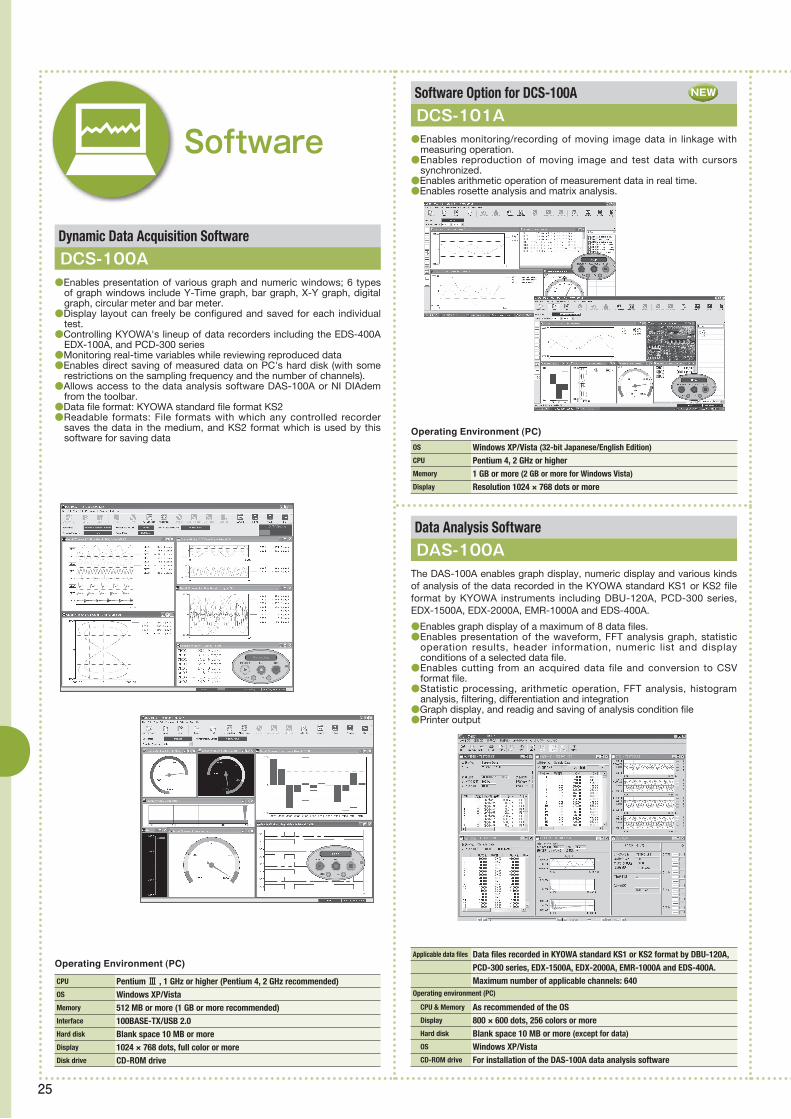
25
Applicable data files Data files recorded in KYOWA standard KS1 or KS2 format by DBU-120A, PCD-300 series, EDX-1500A, EDX-2000A, EMR-1000A and EDS-400A. Maximum number of applicable channels: 640Operating environment (PC)
CPU & Memory As recommended of the OS Display 800 × 600 dots, 256 colors or more Hard disk Blank space 10 MB or more (except for data)
OS Windows XP/Vista CD-ROM drive For installation of the DAS-100A data analysis software
OS Windows XP/Vista (32-bit Japanese/English Edition)
CPU Pentium 4, 2 GHz or higherMemory 1 GB or more (2 GB or more for Windows Vista)
Display Resolution 1024 × 768 dots or more
Software Option for DCS-100A
Dynamic Data Acquisition Software
Data Analysis Software
DCS-101A
DCS-100A
DAS-100A
●Enables monitoring/recording of moving image data in linkage with measuring operation.
●Enables reproduction of moving image and test data with cursors synchronized.
●Enables arithmetic operation of measurement data in real time.●Enables rosette analysis and matrix analysis.
●Enables presentation of various graph and numeric windows; 6 types of graph windows include Y-Time graph, bar graph, X-Y graph, digital graph, circular meter and bar meter.
●Display layout can freely be configured and saved for each individual test.
●Controlling KYOWA's lineup of data recorders including the EDS-400A EDX-100A, and PCD-300 series
●Monitoring real-time variables while reviewing reproduced data●Enables direct saving of measured data on PC's hard disk (with some
restrictions on the sampling frequency and the number of channels).●Allows access to the data analysis software DAS-100A or NI DIAdem
from the toolbar.●Data file format: KYOWA standard file format KS2●Readable formats: File formats with which any controlled recorder
saves the data in the medium, and KS2 format which is used by this software for saving data
Software
Operating Environment (PC)
The DAS-100A enables graph display, numeric display and various kinds of analysis of the data recorded in the KYOWA standard KS1 or KS2 file format by KYOWA instruments including DBU-120A, PCD-300 series, EDX-1500A, EDX-2000A, EMR-1000A and EDS-400A.
●Enables graph display of a maximum of 8 data files.●Enables presentation of the waveform, FFT analysis graph, statistic
operation results, header information, numeric list and display conditions of a selected data file.
●Enables cutting from an acquired data file and conversion to CSV format file.
●Statistic processing, arithmetic operation, FFT analysis, histogram analysis, filtering, differentiation and integration
●Graph display, and readig and saving of analysis condition file●Printer output
CPU PentiumⅢ , 1 GHz or higher (Pentium 4, 2 GHz recommended)OS Windows XP/VistaMemory 512 MB or more (1 GB or more recommended)Interface 100BASE-TX/USB 2.0Hard disk Blank space 10 MB or more Display 1024 × 768 dots, full color or moreDisk drive CD-ROM drive
Operating Environment (PC)
NEW

26
Instrumentation Amplifiers& Related Instruments
● Instrumentation Amplifiers & Related Instruments measurement example
Number of Measuring Channels 1Applicable Transducers Strain-gage transducers Applicable Bridge Resistance 87.5 Ω to 1 kΩ (Up to four 350 Ω
transducers can be connected in parallel.)
Bridge Excitation 10 or 2 VDCInput Range ±3.2 mV/V(including zero adjustment range)
Nonlinearity Within ± (0.02% FS + 1 digit)
A-D Converter 4000 times per second, resolution 24 bitsAnalog Monitor ±(5 V ± 200 mV) (load resistance 5 kΩ or more)
Display 3.5-inch STN color LCD Display area: 73.0 × 55.2 mm 320 × 240 dots, touch panelIndication ±99999Sensor Output Value Transducer output (±3.2 mV/V) is measured at 0.5-second intervals.Measurement Condition Files 32 files (16 for control input) can be saved.Comparator Setting 5; extra high (HH), high (HI), OK, low (LO), extra low (LL); Comparison value, hysteresis width, comparator output logic and using comparactor can be set.Measurement Modes Normal, peak hold, block-specified peak hold, time-specified peak hold, bottom hold, block- specified bottom hold, time-specified bottom hold, arbitrary point hold Detection times, delay time, comparison mode and display mode can be set.Waveform Display X axis setting Y axis setting Waveform start mode, transit level, level transit direction, waveform hold timeSystem Setting Key lock, setting value initialize, backlight illumination time, contrast, clockSelf-check Memory, channelOperation Check Display, touch panel, control input/ output, communication, BCD output, D/A output, SD cardControl Input Zero command, hold command, reset command, waveform command, TEDS command and measurement condition select 0 to 3 Contact or open collector Control Output HH, HI, OK, LO, LL, healthy, abnormal channel, abnormal memory, communication error, SD Open collector Communication RS-232C full duplex systemSD Card Saves and loads setting values, saves and edits the waveform data.Power Supply 85 to 264 VAC, 50/60 Hz; 20 VA or less Dimensions 100(W) × 96(H) × 135(D) mmWeight approx. 1.0 kg (excluding options)
Instrumentation Amplifier
WGA-900A●The measurement waveform can be displayed.●Touch-sensitive 3.5-inch STN color LCD ensures easy operation and monitoring. ●The measurement waveform can be
recorded (optional SD card is necessary).●Characters are large and easy to see.
NEW
●Measurement check of hopper tank
●Body weight measurements of Pet and domestic animal's
●Weight control of hopper tank

27
Number of measuring channels 1Measuring range 0 to 2.5 mV/VBridge excitation 10 VDC/2 VDC, switchableDisplay & Sampling rate –1999 to 19999, 4 times/secNonlinearity Within ±(0.03% FS + 1 digit)Zero & Sensitivity Within ±0.5 μVRTI/°C, Within ±0.0025%/°CPower supply AC line, 50/60 Hz, 20 VA or lessDimensions & Weigh 96 × 96 × 139 mm (excluding protrusions), approx. 1.3 kg
Instrumentation Amplifier
WGA-650B●For strain gage transducers●Up to 4transducers with 350Ω bridge resistance can be connected in
parallel.●High/low limit comparator (relay contact output)●Wide no-load zero adjustment range (±2 mV/V)●Indicated value can be output in a voltage range of 0 to 10 v or in a
current range of 4 to 20 mA.●DIN size (96 × 96 mm) ensures easy installation.
Number of measuring channels 1Measuring range ±0.25 mV/V to ±2 mV/V or moreBridge excitation Applied peak voltage 10 vac, line frequency-synchronized systemOutput 0 to ±5 V (unbalanced load 5 kΩ or more)Power supply AC line, 50/60 Hz, 50 VA or lessDimensions & Weigh 66 × 136 × 220 mm (excluding protrusions),approx. 1.5 kg
★For TEDS, see "About TEDS" on page 07.
Applicable Transducers Strain-gage transducers (full-bridge)Applicable Bridge Resistance WDS-180A: 60 to 1000 Ω, WDS-185AS1: 350 ΩBridge Excitation WDS-180A: 1 V (constant voltage) WDS-185AS1: 2 mA (constant current) Power Supply AA size dry cell × 2Dimensions 66.5(W) × 92.0(H) × 28.0(D) mm (excluding protrusions) Weight approx. 180 g (with manganese dry cells built in)
Instrumentation Amplifier
Compact Digital Indicators
WGI-400A
WDS-180A, 185AS1
●For strain gage transducers (TEDS-compatible)●3 sensitivity registration modes (actual load calibration, sensitivity-registered calibration, numerical value-registered calibration)●4 selectable high/low limit patterns in memory●Level test with desired value input●Optional functions: RS-232C, RS-485, BCD output
●Two models are available for constant voltage or constant current type.●Suitable for simple measurement of load, pressure or displacement in
combination with a transducer. ●Indicates measured values in mm/m or mV/V.●Measure mode enables direct reading of physical quantities in proper engineering unit.●Actual load calibration or sensitivity registration calibration is possible.●WDS-180A provides TEDS reading circuit for easy and error-free setup.●Compact and lightweight (66.5 mm × 92.0 mm × 28.0 mm, approx. 180 g)●Operates on 2 pieces of AA size dry cell which is available anywhere.
Sensor Checker
WDS-500A(For TEDS)
Instrumentation Conditioners
WDC-200C●For strain gage transducers●Up to 4transducers with 350Ω bridge resistance can be connected in parallel.●Noise resistant and suitable for use on production lines●Suitable as long-distance transmission preamplifier or transmitter
●Enables easy checking of strain-gage transducers.●Strain output enables checking of strain amplifiers.●Strain, input/output resistance or insulation resistance can be measured individually by pressing the key.●All these variables can be measured simultaneously in automatic mode.●Enables reviewing of information of TEDS-installed transducers.●Compact and lightweight (66.5 × 112 × 28 mm, approx. 200 g)●Operates on 2 pieces of AA size dry cell which is available anywhere.
WDS-180A
★For TEDS, see "About TEDS" on page 07.
Printing system Thermal line dotPrinting speed & Units Approx. 22.5 mm/s, 6 lines/s, Approx. 250 unitsPower supply 90 to 250 VAC, 50/60 Hz, 24 VDC ±10% Dimensions & Weigh 96(W) × 96(H) × 165.5(D)mm(excluding protrusions),approx. 700 g
Instrumentation Amplifier Printer
442B-K01●For WGA-650B,670B,710C,800C,WGI-400A●Interval operation●Calendew clock provided
★For TEDS, see "About TEDS" on page 07.
Number of measuring channels 1Measuring range ±3.2 mV/VDisplay ±9999Selectable functions BCD data output, Analog conditioner. D-A converter, RS-232C Isolated analog conditioner 8-step comparator Power supply 100/115/200/220 VAC (Select one.)Dimensions & Weigh 72 × 144 × 188 mm (excluding protrusions), Approx. 1.7 kg
Instrumentation Amplifier
WGA-710C (For TEDS)●For strain gage transducers●Up to 4transducers with 350Ω bridge resistance can be
connected in parallel.●Excellent noise resistance makes it suitable for
incorporation into industrial equipment.●Varieties of built-in functions extend the application field.●Comparator function based on preset high/low limits (1 relay contact outplut transfer circuit) and peak hold function●Setting parameters are stored in nonvolatile memory
against power failure.
Number of measuring channels 1Input range ±3.2 mV/V Wide operating voltage range 90 to 240 VAC (10 to 30 VDC optionally available) Indicator 4 digits (±9999)Dimensions & Weigh 96 × 48 × 144 mm (excluding protrusions), approx. 300 g
Number of measuring channels 1Measuring range ±3.2 mV/VBridge excitation 10, 2 VDCDisplay & Sampling rate ±19999, 2000 times/secFrequency response DC to 100 HzNonlinearity Within ±(0.03% FS + 1 digit)Zero & Sensitivity Within ±0.25 μVRTI/°C, Within ±0.01%/°CEMC standard EN61326-1 (class A)Safety standard EN61010-1 (installation category Ⅱ , pollution degree 2) Power supply 100 to 240 VAC ±10%; 20 VA or lessDimensions & Weigh 96 × 96 × 139 mm (excluding protrusions), approx. 1.1 kg
Instrumentation Amplifier
WGA-670B●For strain gage transducers●Connectable in parallel up to 4 transducers of 350 W bridge resistance●Peak hold function and D-A output function provided standard●Model with BCD data output or RS-232C is also available.●Comparator function based on preset high/low limits.●Continuous peak hold function
Number of measuring channels 1Rated output ±10 V, 4 to 20 mAPower supply 100/200 VAC, 10 to 30 VDC(Select one.)EMC standard & Safety standard EN50081-2, 50082-2 / EN61010-1Dimensions & Weigh 44 x 90 x 101 mm (excluding protrusions), approx. 400 g
Instrumentation Amplifier
WGA-100B●For strain gage transducers●Connectable in parallel up to 4 transducers of 350 Ω bridge resistance●Compact, lightweight, low cost, and high-performance capability●Suitable for incorporation into industrial equipment●2 types are available, manual balance system and auto-balance system.●Simultaneous output of voltage and current

28
Automotive Test Equipment
★Interference: ±5% RO (between Fx and Fy )
● Automotive Test Equipment measurement example
Rated capacity 1 kN, 2 kNNonlinearity Within ±1% ROHysteresis Within ±1% RORated output Approx. 0.5 mV/V
Safe overload rating 150%Weight approx. 200g
Rated capacity 200, 300 NNonlinearity Within ±0.5% ROHysteresis Within ±0.5% RORated output Approx. 0.5 mV/V (for both Fx and Fy)
Safe overload rating 120% (for both Fx and Fy)
Weight approx. 100 g
Rated capacity 500 N, 1 kN Nonlinearity Within ±1% ROHysteresis Within ±1% RORated outpu 1 to 2 mV/V Safe overload rating 120%Weight approx. 800 g
Pedal Force Transducers
Change Lever Operating Force Transducer
Hand Brake Force Transducer
LPR-C
LSA-A-S1
LB-B
●Easy to install and use on a variety of pedals●Light weight design reduces effect of
transducer on moment of inertia●Rated capacity : 1kN, 2kN●Cable outlet in optimal location to reduce
cable damage
●Measures the 2-component force initiated by operating the floor shift change lever.
●Measures hand brake tension.
NEW
●Stress evaluation of auto parts and strength test on car body
●Various bench tests of engine and transmission
●Full-scale crash thread, and pedestrian protection tests
●Control stability of real car running and evaluation of riding comfort

29
Rated capacity As specifiedNonlinearity Within ±0.5% ROHysteresis Within ±0.5% RORated output approx. 1 mV/VRotation speed Max. 2000 rpm
Rated capacity As specifiedNonlinearity Within ±1.0% ROHysteresis Within ±1.0% RORated output approx. 1.5 mV/V
Rated capacity Steering force ±20 to 100 N・m Nonlinearity Within ±0.3% ROHysteresis Within ±0.3% RORated output ±2 V Steering angle Rotary encoder output 18000 pulses/360°
Wheel 6-Component Force Measuring System●The sensing part uses no slip ring, and thus
enables running rough road at high speed and ensures easy installation with virtually no protrusion outside the wheel.
●The sensor part is thin and lightweight and is designed like a practical wheel.
●The sensor part transmits detected signals to the onboard memory recorder/analyzer in PCM multiplex telemetry system.
●The onboard memory recorder/analyzer corrects interfrence and angle and then records the data, while monitoring the real-time data in graph or numeric format.
●Large-capacity memory enables long-term data acquisition.●Enables recording of various data by suddenly starting, abruptly braking, stopping and driving backward and forward.
Steering Force/Angle Transducer
SFA-E-SA●Thin and lightweight●Rotary encoder is used to detect steering
angle,thereby ensuring high resolution.●Steering force is output via built-in amplifier, and thus can be obtained with minimal effect of external noise.
Rated capacity ±980.7 to ±9807 m/s2
Nonlinearity Within ±1% ROHysteresis Within ±1% RORated output Approx. 0.5~2 mV/V Safe overload rating 200, 400, 500%Frequency response range DC to 1 kHzWeight approx. 3 g
Rated capacity ±9807 m/s2,±19613 m/s2
Nonlinearity Within ±0.5% ROHysteresis Within ±0.5% RORated output 1.2 mV/V or moreSafe overload rating 200%Frequency response range DC to 4 kHzWeigh approx. 1.4 g
Miniature Crash Test Acceleration Transducers
ASE-A●For crash test●Damping type minimizes the resonance
effect of impact acceleration.
Miniature Crash Test Acceleration Transducers
ASDH-A●For crash test dummies and car bodies
Rated capacity ±9807 m/s2,±19613 m/s2
Nonlinearity Within ±0.5% ROHysteresis Within ±0.5% RORated output 1.2 mV/V or moreSafe overload rating 200%Frequency response range DC to 4 kHzWeigh approx. 1 g
Miniature Crash Test Acceleration Transducer
ASD-A/ASD-B●For crash test dummies and car bodies
Grip-design Steering Force Transducer
●Set transducer on the original steering wheel to measure steering rotational operating force
●Light weight design reduces effect of transducer on moment of inertia
●Rated capacity : 30N, 200N●Does not obstruct activation of airbag
LSG-A,BNEW
Wheel Torque Transducer●Measures the wheel torque of running
vehicle.●Can measure the drive and control torque
while running the vehicle.●Since the transducer is manufactured to the
regular wheel design, it can easily be mounted and used in an optimum condition.
Rated capacity ±1961m/s2
Nonlinearity Within ±1% ROHysteresis Within ±1% RORated output Approx. 1.3 mV/V Safe overload rating 500%Frequency response range DC to 3.5 kHzWeight approx. 1.2 g
Miniature Semiconductor Acceleration Transducers
ASM-200BA●For crash test
Steering Force/Angle Transducer
SFA-F-SA●Thin and Lightweight●Uses high resolution encoder to detect
steering angle (18000pulse / 360deg.)●Easy to install and release●Dedicated monitor and conditioner (optional)
NEW
ASD-A-1K
ASD-B

30
★For TEDS, see "About TEDS" on page 07.
Rated capacity 20 kNNonlinearity Within ±2% ROHysteresis Within ±2% RORated output approx. 2.5 mV/VSafe overload rating 100%
Rated capacity ±9807 m/s2
Nonlinearity Within ±1% ROHysteresis Within ±1% RORated output Approx. 1.5 mV/V Safe overload rating 120%Frequency response range DC to 3.5 kHzWeight approx. 4.3 g ± 0.5 g
Rated capacit ±9807 m/s2
Nonlinearity Within ±1% ROHysteresis Within ±1% RORated output 1.75 mV/V or moreSafe overload rating 150%Frequency response range DC to 2.8 kHzWeigh 4.0 g ±0.5 g
Seat Belt Tension Transducer On-Vehicle Data Logging System for Car Crash TestingMiniature Semiconductor Acceleration Transducers
Airbag Timer
Miniature Semiconductor Acceleration Transducers
LBT-A-20KNSA1 DIS-5000A (For TEDS)ASM-1KCBV/CBH
DIA-512A
ASM-1KBCV/BCH M3
●Measures tension applied to the seat belt by the crushed dummy.
●32 channels / 1 unit●Space-saving installation
(available 128 channel measurement in A4 size installation area)
●S i d e - by - s i d e d i r e c t c o n n e c t i o n to expansion unitsDistributed installation of several units by cascade cable is also available.Maximum number of connected units is 16.
●Maximum sampling speed 100kHz●Visible operational status by display
Battery remaining capacity and charge state can be checked on the panel face indicator.
●Provide TEDS (IEEE1451-4) functionConfo rm ing to TEDS senso r (C las s 2 interface) of International Standard IEEE-145.1to 145.1.4TEDS = Transducer Electronic Data Sheet
●High speed data transfer by 100BASE-TX networkControlled by the DIS-50A Control Software on the PC via LAN interface
●Enhanced self-check functionCheck Function: Sensor check, wire break check, gain check, excitation voltage check,voltage check, memory check, and battery check.
●Applicable to crash test car bodies
●Smaller and lighter than KYOWA forerunner. ●Dimensions are the same as the DIS-5000A
on-vehicle data logging system.●Level of firing current and current output
duration can be set channel by channel.●Firing current status can be saved in internal
memory.●Digital signal is output in synchronization
with current output timing at each channel.●Digita l LED indicator is provided for
enhanced status indication. ●Setting conditions, operation particulars and
errors are logged in nonvolatile memory.
●Applicable to crash test car bodies
Rated capacity 200 NNonlinearity ±3% RORated output approx. 0.75 mV/VSafe overload rating 100%
Rated capacity 15k NNonlinearity Within ±1% RORated output approx. 1.5 mV/VSafe overload rating 120%
Child Seat Belt Tension TransducerSeat Belt Tension Transducer
LBT-B-200NSA1-PLBT-C-15KNSA2●Measures tension of the belt fixing the child
seat.●Compact, lightweight and designed with
easy application in mind
●While designed to be smaller in size and lighter in weight than the forerunner, the LBT-C-15KNSA2 provides a built-in output correction circuit for improved linearity.
Rated capacity 100 kNNonlinearity ±1.5% RORated output 1.0 mV/V or moreSafe overload rating 120%
Child Seat Belt Tension Transducer
LBT-D-100NSA1-HNEW

31
Portable Truck Weighing System
HS Series●Enables easy and accurate measurement of wheel load, axle load, total
weight and left-right weight balance.
Traffic System
Detector
Indicator
Force Sensor Matrix(128 Cells)
Crash Test Analysis Software
Barrier Matrix Test Data Analysis Software
Dummy Qualification Software
Child Seat Dynamic Test Analysis Software
Mounted to a fixed barrier wall, the force sensor matrix detects the impact load applied by the test vehicle when it collides against the barrier wall. The matrix consists of 128 force sensors arranged in 8 columns by 16 rows to enable measurement of the load distributed on the collided surface. The load detecting direction is vertical to the barrier wall. Each force sensor has a rated capacity of 300 or 500 kN.
This software enables the PC to analyze crash test data in accordance with the test standards in Japan, US and Europe. Crash tests are performed with sensors applied to the head, chest, abdomen and other parts of a dummy to measure crash-initiated acceleration, displacement and load. Signals of these sensors are recorded by KYOWA DIS series onboard data acquisition systems and transferred to the PC. The PC filters and processes the data to calculate injury values. Major test methods are frontal impact test and side impact test. Dummies mounted in test vehicles include Hybrid III, side impact dummy and child dummy. This software can analyze data obtained through all these test methods and dummies.
This software enables the PC to analyze the data obtained by colliding a test vehicle against the force sensor matrix. DIS series data acquisition systems are connected to the force sensor matrix to analyze the data. The software also enables the PC to graphically display the data together with video images photographed during testing.
With dummies used for automotive crash and safety tests, laws and regulations require qualification for each of the head, neck, chest, leg, etc. of every type and structure.For the qualification of a dummy, prescribed shock and load are applied to the test site through the tester and the corresponding response is recorded as the data of the dummy mounted sensor and the qualification tester mounted sensor. The acquired data is processed by the proper digital filter defined for the type of qualification. Then, the waveform is operated to calculate the analyzed value, which is checked against the reference value for qualification. This software enables indication of the reference value for qualification on the acquired data waveform and the calculated data waveform.The software is applicable to the qualification of various dummies for frontal collision, side collision and child. Criterion for determining the reference value for qualification is compatible with laws and regulations in Japan, US and Europe.
This software enables the PC to analyze the results of dynamic test (impact-applied safety evaluation test) of child seat in accordance with the test standard. For test data acquisition, DIS series onboard data acquisition system can be used. The dynamic test is performed using the thread impact tester. The child seat with a child dummy is mounted on the test seat placed on a dolly. The dolly is driven at a speed of 50 km/h and is accelerated and decelerated in a prescribed range to record resultant signals. This software enables the PC to calculate injury values of the child dummy by analyzing the acquired data. The analyzed results are displayed and printed in graphs together with injury values.

32
Civil Engineering/Construction Instruments
● Civil Engineering/Construction Instruments measurement example
Rated capacity ±500 μm/m ±1000 μm/mTemperature measuring range −30 to 70°CNonlinearity Within ±1.5%~2%RORated output ±1mv/v(±2000 μm/m) or more ±0.5mv/v(±1000 μm/m) or more
Strain Transducer
BS-AT/BT●The l i nea r expans ion coe f f i c i e n t i s
approximated to that of concrete and temperature effects are minimized, thereby enabling measurement of not only the strain caused by external force but also the strain corresponding to temperature stress.
Rated capacity 2Mpa~10MPaTemperature measuring range −30 to 70°CNonlinearity Within ±10%RORated output ±1mv/v(±2000 μm/m) or more
Stress Transducers
BR-BT●Theoretically backed performance of direct
concrete stress measurement with no conversion from a detected strain quantity
●Landslide monitoring test
●Bridge monitoring tests
●Earth retaing wall displace ment monitoring
Rated capacity ±2000 μm/mNonlinearity Within ±2% ROHysteresis Within ±2% RORated output ±0.625 to±1.25 mv/v
Surface-Mounting Type Strain Transducer
BS-15CT●Surface –Mounting Type

33
Rated capacity ±5°, ±10°Nonlinearity Within ±0.5% ROHysteresis Within ±0.5% RORated output 1.4 mV/V or more
Rated capacity BL-B: 5 to 500 kN BL-E: 1, 2 MNNonlinearity Within ±2% ROHysteresis Within ±1% RORated output 1 mV/V or more
Rated capacity 500 kN to 2 MNNonlinearity Within ±0.8% ROHysteresis Within ±0.5% RORated output 1.25 mV/V or more
Rated capacity ±1000 μm/mTemperature measuring range –30 to 70°CNonlinearity Within ±2% ROHysteresis Within ±3% RORated output ±1 mV/V or more
Rated capacity 200 kPa to 2 MPaNonlinearity Within ±1% RO (within ± 2% RO with 200KP)
Hysteresis Within ±1% RORated output 1 mV/V or more (0.75 mV/V or more with 200KP)
Mounting screw R3/4
Rated capacity 200, 500 kPaNonlinearity Within ±1% RO Hysteresis Within ±1% RORated output 0.85 mV/V ±30% (200 kPa)
1 mV/V ±20% (500 kPa)
Rated capacity Water level 0 to (10, 20, 30) mTemperature measuring range –20 to 60 °CNonlinearity Within ±0.15% ROHysteresis Within ±0.1% RORated output 2 mV/V or more
Rated capacity 300 MPaTemperature measuring range –30 to 70°CApplicable reinforcing bar SD345Deformed reinforcing bar D10 to D32Nonlinearity Within ±1% ROHysteresis Within ±1.5% RORated output 1.85 mV/V or more
Rated capacity 200 kPa to 2 MPaTemperature measuring range –30 to 70°C (BPB-A-T)
Nonlinearity Within ±1% RO (within ±2% RO with 200KP)
Hysteresis Within ±1% RORated output 1 mV/V or more (0.75 mV/V or more with 200KP)
Mounting screw R3/4
Pore Pressure TransducersSmall-Sized Strain Transducer
Small-Sized Pore Pressure TransducerReinforcing-Bar Stress Transducer
Embedment Type Inclination Transducers
Water Level TransducerPore Pressures TransducerHollowed Load Cells
Hollowed Load Cells
BPC-ABS-8FT
BPA-F-SBF-CT
BKJ-A
BWL-ETBPB-A/BPB-A-TBL-B/E
BLW-A
●The double enclosure structure eliminates any effect of lateral pressure.
●Flat filter attached●Enclosure is made of stainless steel.
●Suitable for strain measurement on soldier pi le strut, steel sheet pi le and tunnel support
●Small-sized (outer diameter : 10 mm) and suitable for indoor model experiments
●Shor t-te rm embedded appl icat ion is possible.
●Stress on reinforcing bar is measured by welding both ends of this transducer to the bar.
●The inclination transducer can be installed at up to 20 stages in the guide pipe.
●Available for measurement in single and dual directions
●For measurement of fluctuation of underground water level
●Lightning arrester element built in. Atmospheric pressure
●compensated
●The smal l outer d iameter o f 30 mm enables installation of these pore pressure transducers in a small boring.
●Flat filter attached●Enclosure is made of stainless steel.
●For measurement of load applied to an earth anchor or the support of tunnel arch
●This load cell is a waterproof construction and is thin and l ight the best for the outdoors measurement.
*Stainless steel structure of 32 mmφ by 122 mm long
NEW

34
Rated capacity –30 to 70 °CResolution 0.01 °CMeasuring error ±0.3 °COutput 50 μV/V/°CWeight approx. 120 g
Rated capacity 200 k to 1 MPaTemperature measuring range –10 to 60 °CNonlinearity Within ±2% ROHysteresis Within ±1% ROWeight approx. 120 g
Tension 2.0% strain or less (0 to 1.40 mm)
Compression 0.5% strain or less (0 to 0.35 mm)
Nonlinearity Within ±3% ROHysteresis Within ±3% RORated output approx. 2.5 mV/V
Rated capacit –30 to 70 °CMeasuring error ±0.5 °CWeight approx.10 g
Rated capacity ±5 mmNonlinearity Within ±2% ROHysteresis Within ±2% RORated output ±1 mV/V ±5%Measuring force approx. 9.8 N/5 mm
Rated capacity 0 to (5 to 50) mmTemperature measuring range –30 to 70 °CNonlinearity Within ±1.5% ROHysteresis Within ±1.5% RORated output 1 mV/V or more
Concrete Surface Displacement TransducerTemperature Transducer Large-Sized Soil Pressure Transducers
Crack Displacement TransducerSmall-Sized Temperature Transducer
Joint Transducer
BCD-E-70SBT-100B BEG-A-S
BCD-5BBTS-100AT
BJ-AT
●Easy insta l lat ion us ing a f ix ture and adhesive
●Reusable●Rated capacity
●For embedded appl icat ion (hydraul ic pressure resistance: 200 kPa)
●T h e B E G - A - S s e r i e s s o i l p r e s s u r e transducers are designed for soil pressure measurement of a banking containing large aggregates. This series is used mainly for soil pressure measurement of rock-fill dams containing large aggregates.
●For measurement of crack occurring on rock bed, etc.
●Small measuring force enables installation to soft rock bed.
●The diameter is as small as 5 mm.●Embedded application possible for model
experiments and short-term measurement●Connected to an amplifier constant-current
bridge excitation type for measurement
Small-Sized Soil Pressure Transducers
BEC-A/BED-A●The BEC-A and BED-A series are small-sized
soil pressure transducers having an outer diameter of 30 mm and a pressure-sensing surface diameter of 27 mm. They are used for measurement of soil pressure distribution in short-term or model experiments.
Wall-Surface Soil Pressure Transducers
BER-A-110S●Load cell type design receives no bending
effect of structure.●Cable is attached at right angle or in parallel
to the sensing diaphragm.●Diameter of the sensing diaphragm and
rated capacity
●For measurement of an opening degree of joint, such as between concrete blocks
●Crack of rock-bed can be measured.
*Diameter of sensing diaphragm in mm
Model
BER-110S 100 k to 2 MPa95
Diam.* Rated capacity
Soil Pressure Transducers
BEE-A/BEF-A/BEM-A/BFN-A●Dual diaphragm design within the pressure
medium sealed between the pressure-sensing surface and strain gage-bonded diaphragm enables transmission of minute displacement through enlargement.
●Stainless steel construction
*Diameter of sensing diaphragm in mm
Model
BEE-A
BEF-A
BEM-A
BFN-A
200 k to 2 MPa
200 k to 2 MPa
50 k to 1 MPa
500 k, 1 MPa
160
160
80
70
Diam.* Rated capacity
Rated capacity 200 k to 2 MPaTemperature measuring range –20 to 80 °CNonlinearity Within ±1.0% ROHysteresis Within ±1.0% RORated output 1 mV/V or more
BEF-ABEE-A
BEM-A BFN-A
BEC-A
BED-A

Safetyprecautions
Be sure to observe the safety precautions given in the instruction manual, in order to ensure correct and safe operation.
Manufacturer,s Representative
Specifications are subject to change without notice for improvement.
Cat.No.507-U62
KYOWA ELECTRONIC INSTRUMENTS CO., LTD.Overseas Department:2-4-3, Hitotsubashi, Chiyoda-ku, Tokyo 101-0003, JapanPhome:+81-3-5226-3553 Facsimile:+81-3-5226-3566http://www.kyowa-ei.come-mail:[email protected]
Reliability through integration
Printed in Japan 07/10
www.kyowa-ei.com