kyt 2014 / mico material integrity of welded copper
TRANSCRIPT

RESEARCH REPORT VTT-R-00773-15
KYT 2014 / MICO Material integrity of welded copper overpack – Annual report 2014 Authors: Juhani Rantala, Pertti Auerkari, Anssi Laukkanen, Tom
Andersson (VTT),
Tapio Saukkonen (Aalto)
Confidentiality: Public

RESEARCH REPORT VTT-R-00773-15
1 (17)
Report's title
Material integrity of welded copper overpack- Annual report 2014 Customer, contact person, address Order reference
KYT 2014 Dnro 22/2013KYT
Project name Project number/Short name
MIC02014 81813 Author(s) Pages
Juhani Rantala, Pertti Auerkari, Anssi Laukkanen, Tom 17 Andersson (VTT), Tapio Saukkonen (Aalto) Keywords Report identification code
creep, corrosion, copper, reposito_ry, life VTT -R-00773-15 Summary
The research programme on the creep issues of the nuclear waste disposal canister copper material has continued with long-running uniaxial and multiaxial experiments as well as relaxation testing to support the material modelling activities, which produce appropriate material models to be used in the FE analysis, which will be used to assess the stresses and strains in the critical locations of the canister. The relaxation testing is ongoing and it has proven necessary to use a servo-mechanical testing machine in order to generate good quality test data. The initial FE prediction of strain rates calculated by the LCSP creep model and a relaxation model suggests a clear difference, but this needs to be verified after a better relaxation model is defined based on much more data. The most important result of this year has been the observation of cracking in the oxide particle zone at the friction stir weld root in the longest running CT test, which was terminated after 50 000 hours for sectioning and metallographic investigations. The oxide particles have nucleated creep cavities which have eventually lead to cracking of the oxide particle zone in spite of the low stress state 8 mm ahead of the notch tip. This observation is in line with the earlier results from uniaxial creep tests with a radial sample from the weld root. The weakness only manifests itself in long-term testing because the cavity nucleation and growth process is a slow process. Because of the low strength of the oxide particle zone welding in air should be avoided and vacuum or inert gas should be used instead.
Confidentiality I Public
Espoo 27.2.2015 Written by Reviewed by ~ Accepted by
_J,tfJK~ ~/){ r • ·
G> ~~Jvt~ Juhani Rantala, Senior Maija ~o, Research P~*PohJa ne Scientist Scienti Deputy Head of Researc
Area VTT's contact address
POB 1000, Fl-02044 VTT, Finland; email [email protected]
Distribution (customer and VTT)
KYT 1 copy VTT 1 copy
The use of the name of the VTT Technical Research Centre of Finland (VTT) in advertising or publication in part of this report is only permissible with written authorisation from the VTT Technical Research Centre of Finland.

RESEARCH REPORT VTT-R-00773-15
2 (17)
Preface
This report is the annual report of the project “Material integrity of welded copper overpack”
(MICO2014), including and summarising the experimental, modelling and life assessment
activities as well as the results and status of the project up to the end of 2014. This project is
part of the Finnish national research program [1] on nuclear waste management, 2011-2014
(KYT2014). The research has been carried out by J. Rantala (project manager and
experimental work), P. Auerkari (Principal scientist), A. Laukkanen and T. Andersson (FEA)
/ VTT and T. Saukkonen / Aalto University (scanning electron microscopy, SEM).
For reasons of clarity the structure of this report follows the new task structure of tasks
proposed for the KYT2018 research project PRECO as far as applicable.
The financial support and other guidance by this program, STUK (Finland) and SSM
(Sweden) are gratefully acknowledged.
Espoo, February 27, 2015
Authors

RESEARCH REPORT VTT-R-00773-15
3 (17)
Contents
Preface ................................................................................................................................... 2
1. Introduction ....................................................................................................................... 4
1.1 Background .............................................................................................................. 4
2. Materials and methods ...................................................................................................... 5
3. Relaxation behaviour ........................................................................................................ 6
4. Effect of multiaxiality ......................................................................................................... 8
5. Canister FE analysis ....................................................................................................... 15
6. Training and development of resources .......................................................................... 16
7. Reporting and dissemination ........................................................................................... 16
8. Conclusions .................................................................................................................... 16
References ........................................................................................................................... 17

RESEARCH REPORT VTT-R-00773-15
4 (17)
1. Introduction
1.1 Background
In the repository for spent fuel, the temperature of the canister surface is
expected to peak at about 75-90°C before the first hundred years [2], with
gradual cooling to the level of the bedrock environment (Fig 1). The top
temperature will depend on the rate of wetting in individual disposal holes,
which might vary a lot, depending on the flow of water in the bedrock. The
development of the bentonite swelling pressure will also depend on the rate of
wetting.
For the protective copper (Cu-OFP) overpack of the canister, creep and
corrosion are included as potential damage mechanisms under the repository
conditions [2]. Although relatively mild in usual engineering terms, the
repository conditions imply a technical challenge to life estimation for ensuring
the integrity of the overpack. This is because of the discrepancy between the
longest achievable laboratory test (less than decades) compared to the design life
that is of the order of glaciation cycles (about 105 years) to reduce the
radioactivity of the contents close to the background level. The time difference
by a factor of about 104 also exceeds the usual range of extrapolation from
laboratory experiments to real service conditions in most (or any) comparable
engineering applications.
Fig 1. Predicted temperature evolution at the canister surface for EPR fuel [2];
the red curve assumes dry environment with a 10 mm gap around the canister.
This work will deal with both damage mechanisms to provide a realistic model
for life prediction and long term behaviour of the copper overpack, including in
particular:
0
10
20
30
40
50
60
70
80
90
100
1 10 100 1000 10000 100000
TE
MP
ER
AT
UR
E (
°C)
TIME (years)
Buffer in initialcondition
Saturated buffer
Buffer/rockinterface

RESEARCH REPORT VTT-R-00773-15
5 (17)
assessment of damage mechanisms and their possible interaction: primary
creep, damage interaction in groundwater, impact of oxidation and thermal
degradation
material and life modelling of creep, damage and corrosion, and their
combined action; and
evaluation of long term materials properties of the welded copper overpack,
and the expected impact on the overpack life in the repository.
The project is a part of the Finnish national research program on nuclear waste
management 2011-2014 (KYT2014). The project also includes specific issues
defined by SSM (Sweden).
1.2 Objectives
The principal objectives of the project are
to determine experimentally and model the long term mechanical (creep)
behaviour of the copper overpack, including effects of low stresses,
multiaxiality, defects and reduced ductility; and
to determine experimentally and model the combined creep/corrosion impact
of the expected oxygen potential transition on the predicted life of the
overpack.
The particular technical objectives for the year 2014 have been:
to produce an independent FE verification of the stresses and strains in the
canister
to continue the longest creep tests to beyond 100 000 h to support modelling
and the longest CT-specimen to 50 000 h.
study of creep deformation and electron microscopy (Aalto University)
2. Materials and methods
The OFP copper material for the experiments including friction stir welded
(FSW) material from a full scale section provided by SSM/SKI (Sweden) and
the Swedish program for canister studies. The CT-specimen CS3 was removed
from a cylindrical part (material code T31) and a cover lid (lock TX 82) welded
together. Chemical analysis, short term mechanical properties and initial
microstructures of the materials have been reported elsewhere [2].
For relaxation experiments a 50 mm thick block of OFP copper plate with a
reference code X579 was supplied by Posiva Oy.
Metallography using optical, scanning electron and FESEM/EBSD (Aalto
University) microscopy has been applied for as-new materials and test
specimens after each given testing period. Interrupted testing has been applied
for multiaxial testing to inspect for damage evolution. For load setting and
interpretation of the results, life modelling with extended parametric and other

RESEARCH REPORT VTT-R-00773-15
6 (17)
techniques has been applied, including finite element (FE) analysis for the CT
specimens.
For creep modelling, the combined Wilshire and LCSP models have been
applied and further developed [3, 4] to support robust FE analyses under non-
homogenous stress and strain fields.
3. Relaxation behaviour
In the previous annual report of 2013 [5] it was reported that the FE creep
analysis of the copper canister showed rapid relaxation of stresses in the highly
stressed areas. In this analysis the LCSP creep model was used. However, it is
known that for many other metals a uniaxial creep model does not normally
predict relaxation very well at all, and therefore it was decided that dedicated
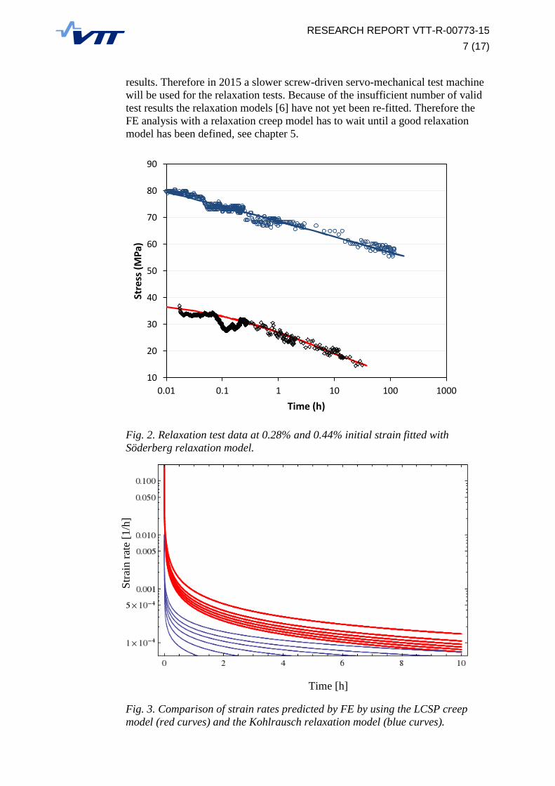
relaxation testing and modelling was necessary. Therefore some initial tests on
OFP copper were carried out in the bellows testing rig at 80°C with initial strains
of 0.28% and 0.44%, and three classical relaxation models were applied. An
example of the data fitting is shown in Fig. 2.The initial results were reported in
a separate report [6]. The Kohlrausch relaxation model was applied in FE in
order to compare the prediction of relaxation by the LCSP creep model and the
initial relaxation model. Fig. 3 shows that the predicted strain rates are very
different by the two models. This example only considers the first few hours
after load application. When more relaxation data becomes available the models
will be refitted and then the behaviour of the whole canister will be predicted by
the LCSP creep model and the relaxation model.
The specimen size in the pneumatic bellows testing rig is rather small: diameter
4 mm and 10 mm gauge length. The relaxation testing standards (EN 10319-1
and 2, ASTM E1012 – 12e1) require a specimen which is typically twice as long
as a standard uniaxial test specimen. This was not feasible in the bellows testing
rig. Therefore it was decided to machine long uniaxial test specimens. However,
for relaxation testing it is important to avoid cold deformation during the
specimen manufacturing and this is very difficult for copper. Therefore it was
decided to machine long specimens with square cross-section using wire erosion.
The cross-section was 8.9*8.9 mm which gives an equal area as in a standard 10
mm specimen. By wire erosion it was possible to machine long specimens with a
80 mm long parallel section without cold deformation. However, the residual
stresses in the plate material caused some slight bending of the specimen, but did
not result in an error greater than 0.01 mm in the final thickness of the relaxation
specimens.
The long relaxation specimens were tested at 80°C in a servo-hydraulic MTS
materials testing machine. Eight tests were carried out with a planned duration of
one week. Axiality of the loading arrangement was checked by strain gauges on
the specimen. The specimen was first heated to the test temperature in a
resistance furnace and temperature was let to stabilize. The initial strains varied
between 0.44% and 20%. The loading rate was fixed such that in all cases the
initial strain was reached in 10 minutes. After this the (constant) strain reading
and the load drop were recorded. Unfortunately only one test produced a reliable
result while in all the other tests either pulses in the hydraulic fluid circuit or
some electrical disturbances caused some load peaks, which invalidated the test
RESEARCH REPORT VTT-R-00773-15
7 (17)
results. Therefore in 2015 a slower screw-driven servo-mechanical test machine
will be used for the relaxation tests. Because of the insufficient number of valid
test results the relaxation models [6] have not yet been re-fitted. Therefore the
FE analysis with a relaxation creep model has to wait until a good relaxation
model has been defined, see chapter 5.
Fig. 2. Relaxation test data at 0.28% and 0.44% initial strain fitted with
Söderberg relaxation model.
Time [h]
Fig. 3. Comparison of strain rates predicted by FE by using the LCSP creep
model (red curves) and the Kohlrausch relaxation model (blue curves).
10
20
30
40
50
60
70
80
90
0.01 0.1 1 10 100 1000
Stre
ss (
MP
a)
Time (h)
Str
ain r
ate
[1/h
]

RESEARCH REPORT VTT-R-00773-15
8 (17)
4. Effect of multiaxiality
This activity consists of two different types of experiments:
Notched bar tests in uniaxial loading
CT-specimens for OFP copper and pure OFHC copper
The notched bar test series was initiated already in 2013 in a M.Sc thesis [7].
The test series has been continued and two tests are currently running. Each test
specimens has two identical notches. Two specimen geometries had been used: a
round specimen with a net diameter of 7.1 mm in a 10 mm cylindrical specimen
and a square specimen with an identical cross-sectional area and notch depth.
The notch root radius is 0.17 mm, machined with wire erosion. Two tests are
currently running. The test results plotted with effective stress are shown in Fig.
4 with the reference data. The data shows that the round and square specimens
produce comparable results and that the notched bar data fall on a line with a
strength reduction factor (SRF) of 0.78.
Fig. 4. Notched bar rupture data with round and square specimens compared
against reference data.

RESEARCH REPORT VTT-R-00773-15
9 (17)
The long-running CT-specimen specimen (CS3) with a friction stir weld, tested
at 175°C at 35 MPa had reached a total testing time of 50 000 hours after which
it was decided that the test is stopped and the specimens will be sectioned to see
whether the crack has started to grow in the middle of the specimen and how the
grain boundary cavity density has developed and how the oxide particle zone has
behaved.
It is seen that practically no crack growth had happened at the notch tip. The
length of the vertical crack in Fig. 5 is only about 30 m. The cavity density in
the middle of the specimen near the notch tip in Fig. 6 is about 600 1/mm2,
which is of the same order of magnitude of what was reported earlier from the
side face of the same specimen during the test interruptions. It was expected that
the cavity density would be bigger in the middle of the specimen. However, the
specimen preparation makes a big difference in how many cavities are seen in
the micrographs, so this result has to be regarded as temporary. The optical and
SEM investigation of the specimen is ongoing.
The most important result of the CT-specimen CS3 is that the oxide particle
region about 8 mm ahead of the notch tip has practically fractured. The location
of the oxide particle region is seen in Fig. 7 with a close-up picture in Fig. 8. In
Fig. 7 it is seen that the oxide particle zone starts about 8 mm ahead of the notch
and bend towards the outer surface of the canister following the process zone of
the friction stir weld. The vertical part of the oxide particle zone has fractured as
is shown in Fig. 8. No cracking was observed in the upper parts of the particle
line in Fig 7, but the specimens will still be studied in more detail with SEM. In
the FE analysis of a copper CT-specimen it was calculated that the vertical stress
8 mm ahead of the crack tip is only about 13% of the maximum vertical stress
ahead of the notch tip. This means that the strength of the oxide particle zone is
strongly reduced, because the oxide particle zone has cracked (Fig. 7 and 8),
while the material in front of the notch tip (Fig. 5) has not even cavitated
remarkably although the vertical stress in front of the crack tip is about seven
times higher than in the oxide particle zone.
The friction stir weld block, from which the CT-specimen was machined, was
welded in air while the current practise is to do the welding in protective (inert
gas) atmosphere. Therefore it is likely that in the new welds there will be much
less oxide particles. Some oxide can appear because there is an oxide scale on
the initial surfaces to be joined, but the amount will be much smaller than in the
pictures shown below. At the root of the weld the proportion of original
(oxidised) surface and weld material is much bigger than near the outer surface
of the canister, so it is likely that the problem will mainly concentrate on the root
area only. However, the behaviour of the same location in the new welds has to
be verified experimentally.
As long as it is not proven that welding in inert gas or vacuum will help avoid
the oxide particles it must be assumed in the FE analysis that the joint line
hooking and the oxide particle region will have a strongly reduced strength. In
the FE analysis of a copper CT-specimen it was calculated that the vertical stress
8 mm ahead of the crack tip is only about 13% of the maximum vertical stress
ahead of the notch tip. The fact that in spite of the low stress state the oxide
particle region had practically cracked is an indication that the oxide particles
will act as nucleation locations for grain boundary cavities. This is in line with

RESEARCH REPORT VTT-R-00773-15
10 (17)
the earlier results [8] of the radial cross-weld creep tests, see Fig. 10. The radial
specimen orientation is shown in the lower left-hand corner in Fig. 9. The
rupture times of the radial specimens in Fig. 10 are close to the reference data at
high stresses, which indicates that the strength loss of the oxide particle zone
does not show at high stresses, but becomes more pronounced at low stresses.
The weakness only manifests itself in long-term testing because the cavity
nucleation and growth process is a slow process. It is therefore recommended
that a suitable damage mechanics model should be applied in the future FE
analysis where the oxide particle zone is modelled.
FSW cross-weld uniaxial creep tests have been performed by SKB in the axial
direction of the cylinder [9], see Fig. 11. These tests have not shown strength
reduction as a result of possible oxide particles at or near the process zone, but
unfortunately no FSW cross-weld testing has been carried out at stresses below
130 MPa, see Fig. 10. This is an obvious shortcoming which SKB and Posiva
have to rectify. This would be recommendable because any weakness produced
by small particles will not show in rupture data at high stresses but rather at low
stresses and long testing times, as shown in Fig. 10. At the conditions where
FSW cross-welds have been tested the rupture strains are better than 30% while
most of the EB cross-weld data fall below this value as shown in Fig. 12.
The long-running uniaxial creep test at 120 MPa and 152°C has been running for
104 000 hours (11.9 years). It has been decided that this test will not be
interrupted anymore for inspections before rupture, because other creep tests
have shown that every interruption adds a new primary creep component to the
creep curve which consumes the deformation capacity of the material and will
shorten the creep life.

RESEARCH REPORT VTT-R-00773-15
11 (17)
Fig. 5. Tip of the natural notch and the joint line hooking in the middle of the
CT-specimen CS3 after 50 000 h of testing. There is hardly any crack growth
and not much cavitation.
Fig. 6. Grain boundary cavitation near the notch tip of the CT-specimen CS3
after 50 000 h of testing.

RESEARCH REPORT VTT-R-00773-15
12 (17)
Fig. 7. The metallographic section from the middle of the CT-specimen CS3
after 50 000 h of testing with the notch and the joint line hooking on the right
and the oxide particle zone 8 mm to the right from the notch tip.
Fig. 8. The cracking in the oxide particle zone in the CT-specimen CS3 after
50 000 h of testing.

RESEARCH REPORT VTT-R-00773-15
13 (17)
Fig. 9. Uniaxial cross weld specimens removed from the FSW in axial and radial
directions.
Fig. 10. Radial cross-weld creep rupture data compared with reference data [8].

RESEARCH REPORT VTT-R-00773-15
14 (17)
Fig. 11. FSW and EB cross-weld rupture data compared against parent metal
(PM) rupture data [9]. PLM = Larson-Miller parameter.
Fig. 12. Parameter Q for localisation of damage as a function of failure strain
for FSW and EB cross-welds compared against parent metal (PM) data [9].

RESEARCH REPORT VTT-R-00773-15
15 (17)
5. Canister FE analysis
The effect of the mesh element size was tested, but this had a minor influence in the
distribution of the elastic-plastic von Mises stress. A more precise definition of the plastic
behaviour has been done on the basis of new tensile test data for OFP copper. As shown in
Fig. 3 the LCSP creep model predicted higher strain rates than the initial version of the
Kohlrausch relaxation model. When the stress distribution of the canister was calculated, it
was seen that the stresses calculated with the LCSP creep model were considerably lower than
the stresses calculated with the relaxation model, see Fig. 13.
As mentioned in chapter 3 much of the relaxation test data has been unsatisfactory and need
to be repeated. When good quality data has been generated the relaxation models will be re-
fitted and the FE analysis will be repeated in 2015.
Fig. 13. The maximum principal stress distribution in the canister after 20 hours calculated
with the LCSP creep model (top) and the Kohlrausch relaxation model (bottom).

RESEARCH REPORT VTT-R-00773-15
16 (17)
6. Training and development of resources
As a new test method relaxation testing was started in 2014 in order to facilitate the definition
of an appropriate relaxation model for the FE analysis. The preparation of the sufficiently
long specimens without cold deformation has been a challenge as described already in chapter
3, but wire erosion seems to guarantee good quality specimens. The relaxation testing with
constant strain loading in a servo-mechanical machine has been another challenge, and it has
proven necessary to use a slower screw-driven servo-mechanical testing machine in the
future.
Another new test method which is being prepared is Small Punch testing. A rig for testing at
room temperature is being built. Small Punch method is a miniature method which allows
small local zones of material to be tested using a coin-shaped specimen with dimensions of
diameter 8 mm and thickness of 0.5 mm. It would be interesting to extract a test sample for
example from the oxide particle zone.
The PhD thesis of J. Rantala is in progress, but some challenging questions have not yet been
answered.
7. Reporting and dissemination
In addition to the normal reporting according to the KYT guidelines a presentation about the
creep research of the nuclear waste disposal canister was held at the ECCC2014 Conference
in Rome 5-7.5.2014 [10].
8. Conclusions
It is essential to perform the FE analysis of the copper canister by using a material model
which consists of models for plasticity, creep and relaxation. Two first elements of these are
well covered, but the development of the relaxation model requires better quality data to
facilitate the development of a relaxation model. This means in practice that a screw-driven
servo-mechanical machine has to be used for the tests instead of a servo-hydraulic machine.
The notched bar test programme is ongoing and has shown comparable results between
specimens with square and round cross-section. When plotted by an effective stress the results
suggest a strength reduction factor of 0.78.
The long-running CT specimen test has shown cracking at the weld root in the oxide particle
zone in spite of the low stress levels far away from the notch tip. This supports the decision to
seal the canister in an inert gas atmosphere or vacuum instead of air in order to avoid the
formation of oxide particles. Before the quality of the new welds has been demonstrated, as a
conservative assumption, a zero strength zone at the joint line hooking and oxide particle zone
will be assumed in the FE analysis.

RESEARCH REPORT VTT-R-00773-15
17 (17)
References
1. Finnish research program on nuclear waste management KYT 2014.
Framework programme for the research period 2010-2014, 16.3.2010. MEE
Publications, Energy and climate 68/2010.
2. Raiko H. 2012, Canister Design 2012. Report POSIVA 2012-13, Posiva Oy.
3. Wilshire B, Bache M B. Cost effective prediction of creep design data for
power plant steels. 2nd Intl. ECCC Conference on Creep & Fracture in High
Temperature Components – Design & Life Assessment. April 21-23, 2009,
Dübendorf, Switzerland.
4. Holmström S. Engineering tools for robust creep modeling. Dissertation/VTT
Publication 728 (2010). VTT, Espoo, 94 + 53 p.
5. J. Rantala, J. Salonen, P. Auerkari, A. Laukkanen, T. Andersson, M. Raunio,
S. Holmström, T. Saukkonen, Material integrity of welded copper overpack –
Annual report 2013, VTT Research Report VTT-R-01173-14, Espoo, 21p.
6. P. Auerkari, R. Pohja, A. Nurmela, Relaxation of OFP copper, VTT Research
Report, VTT-R-00366-14
7. Maija Raunio, M.Sc. thesis, Application and validation of a new approach for
notched bar creep testing of nuclear waste disposal canister copper, Tampere
Univ. of Technology, 2013
8. P. Auerkari, J. Rantala, J. Salonen, A. Laukkanen, S. Holmström, T.
Kinnunen, Effect of defects on low temperature creep of OFP copper, 2nd
Intl. ECCC Conference, Creep & Fracture in High Temperature Components
– Design & Life Assessment, April 21-23, 2009, Dübendorf, Switzerland
9. H. Andersson-Östling and R. Sandström, Survey of creep properties of
copper intended for nuclear waste disposal, SKB Technical Report TR-09-32,
2009.
10. J. Rantala, P. Auerkari, J. Salonen, A. Laukkanen, T. Andersson, S.
Holmström, T. Saukkonen, Creep performance of OFP copper for the final
repository canister, 3rd Intl. ECCC Creep&Fracture conference 2014, Rome
5-7.5.2014