l copy - defense technical information centerl copy usafsam-tr-90-16 feasibility of rectangular...
TRANSCRIPT

'L COPy
USAFSAM-TR-90-16
FEASIBILITY OF RECTANGULAR CONCRETEPRESSURE VESSELS FOR HUMAN OCCUPANCY
AD-A225 958
Jack R. Maison, Ph.D., P.E.
Adaptive Computer Technology, Inc.1856 Lockhill Selma Rd., Suite 105San Antonio, TX 78213
July 1990
Final Report for Period June 1987 - March 1990
I Approved for public release; distribution is unlimited.
Prepared forUSAF SCHOOL OF AEROSPACE MEDICINEHuman Systems Division (AFSC)Brooks Air Force Base, TX 78235-5301

NOTICES
This final report was submitted by Adaptive Computer Technology, Inc.,
1856 Lockhill Selma Rd, Suite 105, San Antonio, Texas, under contract FY33615-
87-C-0605, job order SUPTXXHM, with the USAF School of Aerospace Medicine, Human
Systems Division, AFSC, Brooks Air Force Base, Texas. Lt Col Wilbur T. Workman
(USAFSAM/HM) was the Laboratory Project Scientist-in-Charge.
This effort was funded wholly through the Laboratory Director's Independent
Research (LDIR) Program.
When Government drawings, specifications, or other data are used for any
purpose other than in connection with a definitely Government-related procure-
ment, the United States Government incurs no responsibility nor any obligation
whatsoever. The fact that the Government may have formulated or in any way
supplied the said drawings, specifications, or other data, is not to be regarded
by implication, or otherwise in any manner construed, as licensing the holder
or any other person or corporation; or as conveying any rights or permission
to manufacture, use, or sell any patented invention that may in any way be
related thereto.
The Office of Public Affairs has reviewed this report, and it is releasable
to the National Technical Information Service, where it will be available to
the general public, including foreign nationals.
WILBUR T. WORKMAN, Lieutenant Colonel, USAF, BSC
Chief, Hyperbarics Medicine Division
EOR CEElSCoe, AF, MC, CFS
Commander

UNCLASSIFIED
SECURITY CCASSIFICATION OF THIS PAGEForm Approved
REPORT DOCUMENTATION PAGE OMS No. 0704-0188
la. REPORT SECURITY CLASSIFICATION 10 RESTRICTIVE MARKINGS
Unclassified2a. SECURITY CLASSIFICATION AUTHORITY 3 DISTRIBUTION/AVAILABILITY OF REPORT
Arrroved for - it ruieaste: cstricutio.2b. DECLASSIFICATION / DOWNGRADING SCHEDULE =s unlimited.
4. PERFORMING ORGANIZATION REPORT NUMBER(S) 5 MONITORING ORGANIZATION REPORT NUMBER(S;
6a. NAME OF PERFORMING ORGANIZATION 6. OFFICE SYMBOL 7a. NAMF OF MON.'ORiNG ORGANIZATIONAdaptive Computerf (If applicable)Technology, Inc. j Scnool cf :ercs:a> :ec172. (1'-
6C. ADDRESS (City, State, and ZlPCode) 7o ADDRESS(City State, and ZIPCode)1856 Lockhill Selma Rd Huma,-. Systems iv i: ic-. 5Suite 105 Brooks AYE 7.San Antonio TX 78212
8a. NAME OF FUNDING/SPONSORING r8o OFFICE S'MBOL 9 iROCUREMENT .NSTRUME- IDENTiFtCAT.O% NUMERORGANIZATIONI (If applicable)
8c. ADDRESS(City, State, and ZIP Code) 10 SOURCE OF FUNhDIG NUMBERS
PRO GRAM P ROJ'EC7 7TA S WORK UNITELEMEN NO NO NO ACCESSION NO
031171IT I ' I :.H-
11. TITLE (Include Security Classification)
Feasibility of Rectangular Ccncrete Pressure Vessels for Human
12 PERSONAL AUTHOR(S)Maison, Jack R.
13a. TYPE OF REPORT 13b TIME COVERED 14. DATE OF REPORT (Year. ,ig,, D.,) SP AGE COUNTFinal FROM1990, July 71
16. SUPPLEMENTARY NOTATION
17. COSATI CODES 18 SUBJECT TERMS (Continue on reverse if necessary and iaentify by olock numoer)FIELD GROUP SUB-GROUP Structural Concrete, "restresso,: _ctcrete,
11 02 Chambers, Pressure :essels for Human ccui:an.: (PV,i),07 Hyperbaric :Medicine, !.vrerLarlc _xvcen e ,ner:a.-, Amcr.an
9. ABSTRACT (Continue on reverse if necessary and identify by block number)The technical and cost feasibility of oost-tens!oncd concrete censtructio:. ftr larce,multiplace, elevated pressure medical treatment facilities ista /iishoe.. ,reliminarydesign of a rectangular shaped concrete pressure vessel is descrined. I te c:.amber isdesigned for treatment of 18 patients at pressures u-. to 0 ATA. Itner features of thproposed design include a large rectangular door and a unicue slot ,.;indow .Preliminarydesign is based upon American Concrete Institute (ACI) standards tnat are ",,fef' used bythe construction industry. Detailed structural analysis in. pcrfcrmec on t:.e main compo-nents to demonstrate technical acceptability. The rreliminar' aeszirn is e-timates to cost1/4 that of a conventional facility constructed of steel. .0isk factors trat may increasecost are defined. Conventional strength concrete was found to offer the mo-t economicaldesign. The design and construction of a rectangulIar concrete 11E room ca.-ce done iraccordance with Puality Assurance provisions estal.ished tnrou:. ttcomeinec effortsof the ACI and the ASME Boiler and Pressure Vessel Code. 11n, provisions of ASME SectionIII, Division 2. can and should be incorporated: into the s 1.71 ! -1 rule-.
20 DISTRIBUTION/AVAILABILIT'- ,"r ABSTRACT 2' ABSTRACT SECURITY CLASSIFICATION7 JUNCLASSIFIED/UNLIMITED 0 SAME AS RPT 0 OTIC USERS 0:-.classified
22a NAME OF RESPONSIBLE INDIVID.)UAL 2.b TELEPHONE (Include Area Code) 22c 01; Cc SYMBO,
Wilbur T. Workman,. Lt Col, USAF, DSC 1 (512) 53/-3281 IASAA"/HY
OD Form 1473, JUN 86 Provious onn are obsolete SECURITY CLASSIFICAT ON OF THIS PAGEI iNCAS S . :-,I

UNCLASSIFIEDSECURITY CLASSIFICATION OF THIS PAGE
18. SUBJECT TERMS (continued)
Society of Mechanical Engineers (ASME), Prestressed Concrete Pressure Vessels,High Strength Concrete, American Concrete Institute (ACI), Finite Element Analysis.
UNCLASSIFIEDSECURITY CLASSIFICATION OF THIS PAGE

TABLE OF CONTENTS
ABSTRACT Page 1
BACKGROUND Page 2
PRESTRESSED CONCRETE PRESSURE VESSELS Page 4
HIGH STRENGTH CONCRETE Page 7
NEED FOR PRESTRESSED CONCRETE PVHO Page 9
SCOPE OF STUDY Page 11
APPROACH Page 11
CHAMBER SIZE AND GEOMETRY Page 12
FUNCTIONAL DESIGN Page 18
STRUCTURAL DESIGN Page 19
QUALITY ASSURANCE Page 22
PROPOSED DESIGN Page 24
PRELIMINARY DESIGN Page 28
DETAILED DESIGN Page 28
FINITE ELEMENT ANALYSES Page 29
MAIN TREATMENT CHAMBER Page 29
SLOT WINDOW Page 46
RECTANGULAR DOOR Page 49
COST Page 52
CODE COMPLIANCE Page 55
CONCLUSIONS Page 57
REFERENCES Page 58
APPENDIX A - DETAILED COST BREAKOUT Page 61
iii
ABSTRACT
The technical and cost feasibility of post-tensioned concrete construction for largemultiplace elevated pressure medical treatment facilities is established. A preliminary designof a rectangular shaped concrete pressure vessel is described. The chamber is designed fortreatment of 18 patients at pressures up to 6 ATA. Other features of the proposed designinclude a large rectangular door and a unique slot window. Preliminary design is based uponACI (American Concrete Institute) standards that are widely used by the constructionindustry. Detailed structural analysis is performed on the main components to demonstratetechnical acceptability.
The preliminary design is estimated to cost 1/4 that of a conventional facility constructed ofsteel. Risk factors that may increase cost are defined. Conventional strength concrete wasfound to offer the most economical design.
The design and construction of a rectangular concrete HBO room can be done in accordancewith Quality Assurance provisions established through the combined efforts of the ACI andthe ASME Boiler and Pressure Vessel Code. The provisions of ASME Section III, Division 2can and should be incorporated into the ASME PVHO-1 rules.
o-C , odeS.. .. . . , .i r
3-
PAGE -1-
BACKGROUND
The earliest application of hyperbaric medicine was during World War II for the treatmentof decompression sickness in US Navy "frogmen". In the last 10 years hyperbaric oxygen(HBO) therapy has expanded beyond use by the military to public hospitals and clinics.
The origins of HBO therapy for uses other than decompression sickness can be traced to thepioneering work of the US Air Force. Early in the 1960's the USAF installed small US Navyaluminum chambers to treat aviators that experienced decompression sickness. In 1964 alarge steel chamber was installed at the USAF School of Aerospace Medicine (SAM). Theaddition of this chamber facilitated the growth of the USAF SAM into the major USAFtreatment center for hyperbaric therapy and the center for research on aviatordecompression sickness. In recognition of the importance of the research and treatmentperformed by SAM, the USAF Hyperbaric Center at the USAF School of AerospaceMedicine was established in April, 1974.
The USAF SAM steel chamber is a horizontal cylinder. It is rated at 90 psi$ (7 ATA) andwas fitted with 6 foot diameter circular doors. The original chamber was divided into twoseparate compartments that could be individually pressurized, a so-called "double lock". Theouter lock had doors both to the inner lock and to the outside. The inner lock connected tothe outer lock only. The need for additional usable space eventually led to the conversion ofthe chamber into a single lock unit. The 6 foot intermediate door proved a major annoyanceand was removed.
The pressure vessels that have been used for medical HBO treatment are adaptations fromUS Navy and commercial diving deck decompression chambers (DDC). Commonly, DDCsare steel cylinders with the longitudinal axis laying horizontal. They are 6 foot to 8 foot indiameter and are portable, skid mounted and fitted with lifting brackets for ship boardhandling. They have small circular doors ranging from 22" to 30" diameter and small (4" to 6")round acrylic windows. Operational depths range from 300 to 1500 feet (20 - 100 ATA).
Safety certification of these DDCs and the associated personnel transfer capsules (PTC)provided the stimulus for the development of an industry specific set of rules for the designof pressure vessels for human occupancy (PVHO). Problems of concern to the divingindustry included shipboard handling loads, selection of tough, fracture resistant steels andthe design of transparent windows. Also of concern, was the design of the PTC which wasexposed to external pressure.
The primary rules for the design of the DDC and PTC came from the ASME Boiler andPressure Vessel Code, Section VIII (ref. 1). The ASME rules were widely accepted asconservatively safe but restrictive and in some cases incomplete. The diving communitypetitioned the ASME to form a special Standards group that would address the specialF roblems of DDC and PTC vessels. The PVHO Committee was formed in 1974 and workedor 10 years to produce the ANSI Safety Standard for Pressure Vessels for Human
Occupancy (ref. 2). The primary emphasis of the PVHO activity was the diving communityboth military and commercial; however, other organizations such as the Underseas MedicalSociety envisioned a wider application of PVHO rules.
The pressure vessel needs of the medical HBO are unique but not unlike those of the divingindustry. Both groups needed rules for design and certification of acrylic windows, a topicthat the ASME Boiler and Pressure Vessel Code steadfastly refused to consider. Both alsoshared concern for occupant safety and the need to prevent a sudden loss in pressure due tosafety valve discharge. One topic that brought the HBO medical community into fullinvolvement with the PVHO Committee was the use of monoplace chambers for medical
PAGE -2-

treatment. The monoplace HBO chamber is an acrylic plastic tube just large enough for oneperson. These small portable units expose the occupant to 100% oxygen and in so doing posea potential for fiie. The monoplace chambers are economical, but they have significantlimitations, particularly, when the occupant needs assistance (ref. 3). The PVHO Committeebecame involved when its design rules for submersible windows were applied to the acrylicplastic tube of monoplace chambers.
The special needs of commercial and military medical HBO treatment facilities dwarfedthose of monoplace chambers and soon became a major extension of the scope of interest ofthe PVHO Committee. These medical HBO facilities which treat many patientssimultaneously are installed in or adjacent to hospitals and clinics. Multiplace PVHOs aregenerally steel cylinders, usually horizontal, 84-96" diameter and pressure rated at 75-100psig (6-7 ATA). All are double lock to allow patient or attendant exchange withoutdepressurizing the main treatment chamber. Most are fitted with a rectangular door forpatient egress. The door is about 3 feet wide by 6 feet tall. Commercial medical HBOchambers are fabricated by pressure vessel shops to the rules of PVHO-1 (ref. 2) and aretruck transported to the HBO Treatment Center.
The US Air Force is the major sponsor of HBO hospital facilities. Since 1985, two majormulti chamber HBO treatment f' :ilities have been installed. The facility at Wright PattersonAFB, the WPCHF (Wright Patterson Clinical Hyperbaric Facility) has been in operation forabout one year. The David Grant (DGCHF) complex at Travis AFB, CA. is due tocommence operation soon. A third facility is planned for Portsmouth Naval Hospital.
All of the USAF facilities consist of three steel pressure vessels. The primary treatment isdone in a 20 to 23 foot diameter sphere or upright cylinder. Emergency treatment andoverflow is assigned to an adjacent upright (longitudinal axis vertical) cylinder varying in sizefrom 11 foot diameter on the first installation at WPCHF to a 14 foot diameter for the mostrecent facility. A third upright cylinder acts as the lock to the other chambers. The locks varyin size from 11 to 12 foot diameter. The three chambers are interconnected with rectangularpassageways. The doors to the outside and at either end of the passageways arerectangular with a clear opening of 3 feet by 6 feet. All windows are circular with themaximum size being 15" diameter.
The primary or main treatment chamber of the USAF facilities is constructed at thehospital site. The other smaller chambers are built in pressure vessel shops and transportedby rail or truck. Final assembly consists of field welding the rectangular passageways to thechambers.
Virtually all of the multiplace medical PVHOs have been built from steel using conventionalpressure vessel fabrication technology. The exceptions are few, two place acrylic and steeland all stainless steel PVHOs and some converted aluminum diving recompressionchambers. Other materials have been suggested; fiberglass composites for collapsible andportable applications and prestressed concrete for the large hospital installations.
PAGE -3-

PRESTRESSED CONCRETE PRESSURE VESSELS
Prestressed concrete has a history of being used for pressure vessels. Concrete is a preferredconstruction material because of its low cost, but concrete has a major limitation whenapplied to pressure vessels. Concrete is strong in compression but exceedingly weak whenpulled in tension. An inherent requirement of a structure to contain pressure is its ability toresist the tensile loads of an expansive pressure.
The combination of concrete and steel wire in prestressed concrete is an excellent matchingof the complementary strengths of two materials to overcome the other material'slimitations. The steel wires have the opposite characteristic to concrete. Steel wires are goodin tension but buckle when compressed. Prestressed concrete combines concrete and steel insuch a way as to precompress the concrete and pretension the steel. Tensile cracking of theconcrete is inhibited and the steel wires are pre-elongated. The initial prestressing must besufficient to produce a resultant compressive preloadin the concrete after time dependenteffects of creep in the concrete and relaxation in the wires occur.
Prestressed concrete is suitable for large field fabricated structures. Perhaps its earliestapplication in pressure vessels was in agricultural silos. In the 1930's, concrete silos werecircumferentially prestressed to resist the internal pressure of grain and silage. Bridge andskyscraper applications of prestressed concrete followed thereafter. Today prestressedconcrete is widely used in civil engineering structures throughout the world.
A major development of prestressed concrete for pressure vessels initiated in Europe in the1960's. Europe's need for energy led to the development of PCRV's (Prestressed Concretenuclear Reactor Vessels). Prestressed concrete was used for the construction of more than 20gas cooled nuclear reactors that operated at pressures from 350 to 700 psig. These weremassive pressure vessels ranging in size from 50 foot diameter up to more than 100 feet. Allused circular prestressing to resist the tensile hoop stresses and a combination of linear andcurved tendons carried the end loads. Gas cooled reactors were never very popular in the US.Domestic utilities preferred boiling water reactors that operated at pressures in excess of2500 psig. In the 1960's, concrete strength was insufficient to contain these higher pressures.
One gas cooled prestressed concrete reactor was built in the US at Fort Saint Vrain,Colorado. It was an upright cylinder 75 feet high with an internal cylindrical cavity diameterof 31 feet. Six vertical buttresses, which provided tendon anchorage sites, increased the wallthickness from a nominal 9 feet to 15 feet. The top and bottom slabs were 15-1/2 feet thick.The PCRV was prestressed using 600 ton tendons. The circumferential or hoop prestress wasgenerated by linear tendons deformed into a half loop and anchored at the buttresses. Theend load was transferred from arched tendons in the end to vertical tendons in the cylinderthrough the concrete. The Fort St. Vrain PCRV weighed 15,000 tons and contained 6600cu.yd. of 6,000 psi concrete. This reactor, the only PCRV built in the US, has been closed.
In anticipation of other gas cooled reactors being built in the US and to satisfy the NuclearRegulatory Commission's Quality Assurance Standards for the concrete nuclear containmentstructures, the nuclear subcommittee of the ASME Boiler and Pressure Vessel Codeinitiated development of a special Division dealing with concrete. In 1971, the ASME begana joint effort with the American Concrete Institute (ACI). The rules governing concrete fornuclear reactor pressure vessels were first published in 1976 as Section III, Division 2 (ref. 4).
Also in the early 1970's, the US Navy was developing a deep ocean capability. The DSRV(Deep Submergence Rescue Vehicle) and the DSSV (Search Vehicle) were seen asvanguards of a new class of deep submergence hardware. Testing of this hardware was anecessity. Failures at sea were costly and the remnants often unrecoverable. Deep ocean
PAGE -4-

simulators were available at many Navy Labs, but even the newly commissioned 12 footdiameter, 20,000 psi test vessel built at the Annapolis Naval Ship Research and DevelopmentLaboratory was thought to be too small. A major study was initiated in 1971 to investigatealternative design concepts for large high pressure vessels.
The study (ref. 5), examined construction methods for chambers of two extreme sizes andpressure ratings. The smaller chamber was a 20 foot diameter by 60 foot long, 30,000 psichamber for component testing. The second was to be a 75 foot diameter, 600 foot long, 4000psi pressurized facility for proof testing of full scale combat submarines. Concrete was foundto be the most feasible construction method for the large tank. The study established theprimary technological risk as development of high strength concrete. The 4000 psig designpressure was achievable only at concrete compressive strengths of 14,000 psi. At the time ofthe study, commercial concrete strengths of 5000 to 6000 psi was considered good practice.
In the late 1970's, interest in large concrete chambers as alternatives to steel PVHOs revived.NAVFAC (Naval Facilities Engineering Command) sponsored a cost comparison study (ref.6) of two chambers; one a 15 foot diameter, 1000 psi PVHO and the second a 10 footdiameter, 20,000 psi research and hardware test vessel. The pruposed concepts usedconventional circular prestressing of concrete. The cost comparison showed a 70% costsavings for the manned 1000 psi tank over conventional steel.
The issue of concrete for pressure vessels was also of interest to the Department of Energy inthe mid 1970's. One solution proposed for the oil shortage was coal gasification. An ACICommittee was formed to develop standards for large pressurized concrete cylinders for coalgasification plants. Large high pressure, high temperature retorts were needed to convertcoal into gasolene. Pressures of 3000 psi on diameters comparable to PCRV's required wallsof high strength concrete 10 to 30 feet thick. Concrete was found to be an economicalalternative to steel. Savings were estimated to be 70% (ref. 7).
During the 1980s, the oil crisis became a glut and interest in coal gasification disappeared.The ACI group sought other applications where concrete was cheaper than steel. Potentialuses were offshore storage tanks and hydrocracking vessels and vacuum stills in oil refineries.In 1988 the group became dormant for want of a specific application that needed a concretesolution.
The USAF also was conducting cost studies of HBO chambers in the late 1970's. A costtradeoff investigation compared horizontal and vertical cylinders and rectangular concreterooms (ref. 8). The operational scenario usdu two interconnected 6 ATA chambers. Thelarger chamber accommodated 10 patients and 2 medical attendants and would be used forscheduled HBO therapy. A second smaller chamber, for emergency treatment, was sized for2 patients with 2 attendants.
Options for the main treatment chamber were:
1.) a 12' diameter by 25' long horizontal steel cylinder,
2.) a 19' diameter vertical cylinder, or
3.) a 10' wide, 25' long by 8'high rectangular concrete room.
The emergency treatment chamber alternatives were:
1.) a 12' diameter by 10' long horizontal steel cylinder,
PAGE -5-
2. , 1. !2' diameter vertical cylinder, or
3.) a 10' square by 8' high rectangular concrete room.
Preliminary cost estimates showed the cost of the steel chambers to be in the $125,000 to$169,000 range. The concrete chambers showed a 30% to 40% cost savings.
In 1984, the option of vertical versus horizontal cylinders was examined in more detail (ref.9). This study provided the basis for size and configuration of Wright Patterson ClinicalHyperbaric Facility (WPCHF). A vertical cylinder was selected over horizontal for tworeasons: (1) it gave the maximum floor space for chamber volume and (2) it reducedinterference in patient movement.
This investigation also showed that the number of patients that can be treated is directlyproportional to floor area. The study developed a rational for assuming that 36 ambulatory or20 litter patients would be treated per day. Further, experience had shown that 2pressurizations (dives) could be made in one work shift. Accordingly to minimize the numberof operational shifts, the ideal capacity of the main chamber was 18 ambulatory patients. Thistranslated into a 22 foot diameter upright cylinder.
It was also shown that a smaller 14 foot chamber had a lesser first cost but the additionaloperational expenses of running a second shift canceled the first cost differential in 9 years.
he main treatment chamber in the WPCHF is a 22 foot upright cylinder.
PAGE -6-

HIGH STRENGTH CONCRETE
Many studies have shown that high strength concrete is either desirable or mandatory forconcrete pressure vessels. In the last few years higher strength concrete has gained wideattention. It is used increasingly in high rise buildings where its greater elastic modulus(stiffness) reduces building sway. As building height increases, motion at the upper floorsbecomes the design constraint. The high strength which is specified for stiffness in thebuilding columns also reduces column size and thereby increases the leaseable floor area.This combination of increased stiffness and more floor area has led to pioneering advancesin commercial concrete strength.
The evolution in concrete strength reads as follows:
1968 - 7,500 psi in Chicago (Lake Point Tower);
1975 - 9,000 psi in Chicago (Water Tower Place);
1984 - 10,000 psi in Seattle (Century Square Bldg.);
1987 - 10,000 psi in Toronto (Scotia Plaza), 10,000 psi was specified but testsshowed 13,000 psi was achieved;
1988 - 12,000 psi in Chicago (Prudential Plaza);
1988 - 12,000 psi in Atlanta (Portman Properties), 12,000 psi offered $5/sq.ft.savings over steel on a 1.4 million sq.ft. building;
1988 - 12,000 psi in Chicago (South Wacker Tower), 12,000 psi was used forreasons of economy although 14,000 psi was considered. At946 feet South Wacker Tower is world's tallest concretebuilding;
1988 - 19,000 psi in Seattle (Two Union Square), 19,000 psi is the currentrecord for high strength concrete.
The 19,000 psi concrete used in Seattle was initially specified as 14,000 psi with an extremelyhigh elastic modulus of 7,200,000 psi. For comparison, conventional 6,000 psi concreteexhibits an elastic modulus of 4,700,000 psi. The high elastic modulus dictated the 19,000 psiconcrete strength. Many of the concrete test specimens failed at > 21,000 psi.
This very high compressive strength concrete was achieved in a commercial batch plantthrough an extraordinary quality assurance (OA) program. The mix design specified anextremely low water to cement ratio of 0.22 (conventional concrete is 0.45). In addition, avery high cement content and strong, small (3/8") glacial aggregate was used. Silica fume, avery strong and fine aggregate filler was also a key ingredient. To work this stiff mix asuperplasticizer was added.
Predictions are now being made of 25,000 to 40,000 psi concrete in the 1990s (ref. 10).
High strength concrete poses some new problems. Testing limits are being approached andconventional design rules are being questioned. Most test labs are equipped to evaluate< 6,000 psi concrete. Typically, they have a 300,000 lb. test machine which is adequate fordestructively testing a standard 6" diameter by 12" long test cylinder. Testing of 20,000 to30,000 psi concrete will require as much as a million pound test machine. Adding further to
PAGE -7-

the cost of testing is the substitution of lapped ends on the test cylinder for the end cappingcompound that fails at 14,000 psi.Of greater concern than testing costs is the potential discrepancy introduced by high strengthconcrete on the ACI Building Code (ref. 10). The ACI (American Concrete Institute) Code
is used for buildings and other civil engineering structures. It is adopted throughout the USby local building codes as the regulatory guide for concrete construction. The ACI Code, likethe ASME Boiler and Pressure Vessel Code, develops minimum requirements for safety.The basis of the ACI rules is experimental data on low to medium strength concrete. TheACI committee members have expressed concern that use of high strength concrete isspreading faster than knowledge of its engineering properties. The actual use of highstrength concrete in other than high rise buildings hasbeen quite small, but is growing.
To address these doubts the Portland Cement Association fund zd research on beams madefrom 17,000 psi concrete. The initial research findings supported only a minor change tocurrent ACI rules for design with high strength concrete. Additional requirements for shearreinforcement have been proposed for local regions at stirrups and ties. More confirmatorystudies are underway, but at this time the current rules appear to be adequate for concretestrengths up to 10,000 psi
PAGE -8-

NEED FOR PRESTRESSED CONCRETE PVHO
Why is there interest in concrete for PVHO's?
A defined need exists for additional multiplace treatment facilities. The USAF hasrequirements for additional medical PVHOs. It has been proposed that each militaryhospital district offer HBO treatment. At present in the ten hospital districts two have HBOfacilities and a third has one in the design stage.
The cost of these facilities is appreciable. The steel vessel cost is on the order of $1-1/2million. Cost reductions are desired. Prestressed concrete is seen as a source of cost savings.Previous studies, mentioned above, report cost savings ranging from a low of 30% for lowpressure vessels to as much as 70% at higher pressures.
Another significant factor affecting new construction of multiplace PVHOs is the reality thatfar fewer domestic pressure vessel manufacturers are in business today than five years ago.Many of the PVHO vessel fabricators simply abandoned the business. Many were steelfabricators that served the diving industry. As the demand for oil fell commercial divingalmost disappeared and so did these builders. They found it difficult to support hightechnology staffs when relatively few systems were being built. Also, major projects werefrequently awarded to the lowest bidder rather than the most technically capable.
A siificant feature of concrete PVHOs is the potential for design of rectangular rooms.Steel pressure vessels are cylindrical or spherical; a rectangular vessel is an anomaly. TheASME Boiler and Pressure Vessel Code, Section VIII, (ref. 1), devotes major sections to thedesign of curved pressure vessels. While rules for rectangular vessels are provided in anAppendix, the rectangular vessel is considered a special shape. Experience with therectangular passageways used in the WPCHF and DGCHF clearly established that even forsmall rectanular vessels, (3 foot wide by 6 foot high) the ASME requirements produceextremely thick and expensive sections. The prospect of a steel rectangular vessel of a sizecomparable to the 23 foot main treatment chamber of DGCHF is low, because of hightechnical risk and high cost.
The advantages of rectangular rooms are many.
1. Rectangular treatment rooms give better space utilization. A conventional flat wallyields more usable floor space for litters and wall space for equipment and windows.Less gas volume is needed since the wasted volume in the curved heads of aconventional steel tank are eliminated. With a rectangular room the HBO facilityrequires less hospital space. It can be located on one floor whereas current facilitiesrequire a separate hu:,pital addition.
2. Rectangular rooms are believed to be more acceptable to patients and hospital staffthan the "Space Ship" appearance of steel chambers. A rectangular treatmentchamber willappear similar to other hospital facilities.
3. Rectangular chambers facilitate the use of larger doors. The curved walls of steelPVHOs restrict the location of the massive doors and encroach on usable chamberfloor area. Current practice is to design the door to swing on hinges, a sliding door isfeasible in a rectangular chamber.
4. Larger and rectangular shaped windows are feasible in rectanu lar PVHOs. Circularwindows are commonly used today. This geometry is in part a historical consequenceof their use in cylindrical pressure vessels. Circular windows can be traced to round
PAGE -9-
piping penetrations in steel pressure vessels. Rectangular vessels with flat wallsacilitate the specification of a rectangular or slot shaped windows. A slot shaped
window offers improved visibility into a large chamber.
5. Laminar gas flow across the HBO chamber is difficult to achieve in a sphere orvertical cylinder but can be readily produced in a rectangular room. Laminar flowrequires less recharge gas flow to eliminate carbon dioxide and odors. It also offersmore uniform and predictable temperature control.
6. A rectangular concrete room adapts to conventional building architecture and canbe constructed by the hospital building contractor. The advantages in dealing withone contractor are many. First, the interface to a specialty steel PVHO fabricatorand its attendant scheduling problems are eliminated. A single contractor will be in abetter position to control and thereby reduce costs and schedule.
Concrete for PVHOs is not without shortcomings. As a new material for HBOs acceptancemay be slow. No rectangular concrete PVHOs have been built and accordingly somedifficulties may lie hidden. It is not certain that the available codes are applicable. ShouldACI or ASME be used? Will cities and states accept concrete PVHOs?
Technical issues need to be examined. Does outgassing and contamination frommicrofissures in the concrete pose a potential health hazard? Is a liner required? Is theconcrete inspectable? Will high strength state-of-the-art concrete be required? Thestructural details may be formidable in a rectangular vessel. Cylinders are used for pressurevessels because pressure is best resisted by a curved geometry. Rectangular vessels havesharp comers, a feature that raises stresses and is avoided in conventional pressure vesseldesign. Local reinforcement at doors, windows and penetrations also needs to be examined.
In summary, concrete pressure vessels have a mixed history. A number of studies have showncost advantages but few have been built to validate the studies. Recent technical advances inconcrete strength suggest that this mundane material may be suitable for the high qualityrequirements of Pressure Vessels for Human Occupancy.
PAGE-10-

SCOPE OF STUDY
The objective of this study was to determine the technical feasibility of a rectangularconcrete pressure vessel for medical PVHOs.
The scope of the study began with a review of the literature to establish current practice inconcrete pressure vessels. Using state of the art knowledge, a preliminary design of arectangular concrete pressure vessel was to be developed. Considerations of chamber sizeand shape and the special needs of medical PVHOs were to be addressed.
A preliminary structural analysis was to be performed to prove technical feasibility. Thestructural analysis was to include the main treatment chamber, the rectangular or slot windowconcept and a large rectangular door with a large circular window.
An order of magnitude cost for the rectangular concrete vessel was to be calculated and acost comparison made to an equivalent steel vessel.
An evaluation of available Codes for applicability to concrete PVHOs was also included inthe scope of the study.
APPROACH
The approach taken to determine the suitability of a rectangular concrete PVHO firstestablished chamber size requirements to meet anticipated patient loads. Candidate designswere conceived to satisfy these size requirements. The technical acceptability of thecandidate design was evaluated using conventional concrete design methods. Designconfirmation of the candidate design followed. Detailed stress analysis was used to confirmstructural adequacy.
The cost of the candidate design was estimated and compared to historical cost data for steelPVHOs. If cost savings were not found, the candidate design was revised and the designprocess repeated. Candidate designs were iterated until an acceptable technical and costdesign was found.
Finally, an evaluation was made of the available Codes for applicability to rectangularconcrete PVHOs.
PAG E-1-

CHAMBER SIZE AND GEOMETRY
The determination of the size and shape of a medical HBO treatment chamber is derivedfrom operational requirements. The number of patients and area requirements per patientare coupled with the operational costs of staff to determine the floor area needed.
The initial USAF study (ref. 8) presumed a load of 10 patients and 2 attendants. The laterinvestigation (ref. 9) showed that staff operational costs have a significant impact and thatwithin a decade of operation, larger chambers operated less frequently, are the cost effectivechoice.
Statistics on chamber size and average area per patient for the USAF Clinical HyperbaricFacilities (CHF) are compiled in Table 1.
TABLE 1 - PVHO SIZE and PATIENT LOAD
WPCHF (built in 1985, operational in 1987)MAIN - 22' cylinder - 18 patients (21 sq.ftJpatient)
EMERGENCY - 11' cylinder - 6 patients (16 sq.ft./patient)LOCK - 11' cylinder
DGCHF (built in 1988)MAIN - 23' sphere - 18 patients (23 sq.ft./patient)EMERGENCY -12' cylinder - 6 patients (19 sq.ft./patient)LOCK - 12' cylinder
PNHCHF (planned for 1992)MAIN - 20' sphere - 16 patients (20 sq.ft./patient)EMERGENCY - 14' cylinder - 10 patients (15 sq.ft./patient)LOCK - 12' cylinder
Table 1 suggests that the main treatment chambers of the future should accommodate 16 to18 patients per dive. The experience at WPCHF has been 30 + patients per day and two divesper 8 hour shift. This level of usage supports the size of the main chambers listed in Table 1.
The required floor area of the main chamber is derived by multiplying the number ofpatients per dive by the area that the patients' chair or litter covers to arrive at anapproximate total area. Additional area is set aside for clearance around the chair and litterand for aisles. Aisles are assumed to be 4 feet wide.
The area required for the litter and wheel chairs used in USAF CHF are:
litter dimensions = 30"W x 78"L (nominal 3'x 7')
chair dimensions = 22"W (nominal 3'x 3')
large wheel chair = 28"W x 45"L (considered as a litter)
The projected mix of chairs and litters is 50%. In the analysis of area requirements, the
PAGE -12-
assumption of 100% litters or 100% chairs is made however.
Other floor layout considerations are:
1.) all patients must have access to at least one aisle,
2.) all aisles must lead to a door,
3.) the door is at least 5' wide and
4.) only one door is needed for patient entry.
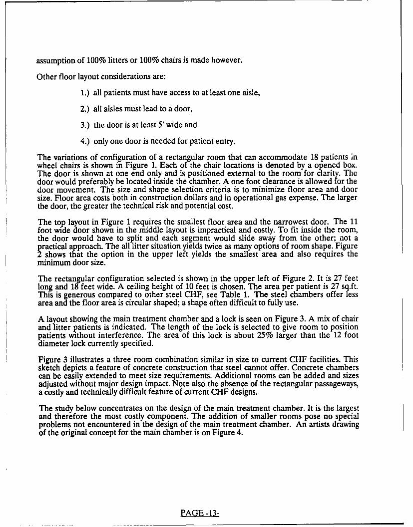
The variations of configuration of a rectangular room that can accommodate 18 patients inwheel chairs is shown in Figure 1. Each of the chair locations is denoted by a opened box.The door is shown at one end only and is positioned external to the room for clarity. Thedoor would preferably be located inside the chamber. A one foot clearance is allowed for thedoor movement. The size and shape selection criteria is to minimize floor area and doorsize. Floor area costs both in construction dollars and in operational gas expense. The largerthe door, the greater the technical risk and potential cost.
The top layout in Figure 1 requires the smallest floor area and the narrowest door. The 11foot wide door shown in the middle layout is impractical and costly. To fit inside the room,the door would have to split and each segment would slide away from the other; not aractical approach. The all litter situation yields twice as many options of room shape. Figureshows that the option in the upper left yields the smallest area and also requires the
minimum door size.
The rectangular configuration selected is shown in the upper left of Figure 2. It is 27 feetlong and 18 feet wide. A ceiling height of 10 feet is chosen. The area per patient is 27 sq.ft.This is generous compared to other steel CHF, see Table 1. The steel chambers offer lessarea and the floor area is circular shaped; a shape often difficult to fully use.
A layout showing the main treatment chamber and a lock is seen on Figure 3. A mix of chairand litter patients is indicated. The length of the lock is selected to give room to positionpatients without interference. The area of this lock is about 25% larger than the 12 footdiameter lock currently specified.
Figure 3 illustrates a three room combination similar in size to current CHF facilities. Thissketch depicts a feature of concrete construction that steel cannot offer. Concrete chamberscan be easily extended to meet size requirements. Additional rooms can be added and sizesadjusted without major design impact. Note also the absence of the rectangular passageways,a costly and technically difficult feature of current CHF designs.
The study below concentrates on the design of the main treatment chamber. It is the largestand therefore the most costly component. The addition of smaller rooms pose no specialproblems not encountered in the design of the main treatment chamber. An artists drawingof the original concept for the main chamber is on Figure 4.
PAGE -13-
9 X 2280 sqft 5' DOOR
6 X 3
H2 qt1'DO
323 sqft 5' DOOR
FIGURE 1 -CHAIR ARRANGEMENT OPTIONS14

-HH 7FT - H- -HFi-
2 551 sqft 15' DOOR
9 X2 1504 sqft 5' DOOR I I H
731 sqft 11' DOOR
616 sqft 14' DOOR
I II I I I'l I--- I -
-H F- -I- -H H-
-- - - I I
5X4576 sqft 5' DOOR I
SCALE = 12'5X4
720 sqft 5' DOOR
FiGURE 2 - LITTER ARRANGEMENT OPTIONS15

5'-PATIENWT18' DOORS TREATMENT LOCK
27' 8' -
3'-SIDE DOOR
TREATMENT
18' TREATMENT #1 LOCK #2
27' ofLa2
FIGURE 3 - TREATMENT CHAMBER LOCK COMBINATIONS16

% Ol
T.~* 7
kl1
~-.J*4-4
. ~ 0
U
El
17--

FUNCTIONAL DESIGN
The functional aspects affecting the main chamber design include the patient load, alreadydiscussed, patient handling and movement, patient comfort and patient monitoring orviewing.
The main chamber should accommodate 18 patients. To ease the movement of patients intoand within the room a large door and wide aisles should be provided. The desired dooropenin& is 48-60" wide and 76-84" high. The door should be clear opening and should beflush with the floor to permit one attendant to move one patient. The lifting of chairs orlitters across the door frame is to be avoided.
Patient viewing is improved with large windows. Current practice of 15" circular openingslimits the observers field of view. Long slot windows provide a better viewing angle. Theviewer experiences less fatigue as sight along the room becomes possible. Also the chamber
interior lighting requirements may be reduced by use of slot windows as skylights. Slotwindows should be specified for rectangular chambers.
The rectangular shape of the room will be less disconcerting to the patient than the curvedwalls of a steel CHF. It is more "hospital" like and less claustrophobic. The slot windowsshould further reduce patient anxiety.
The chamber is the key component in the PVHO system. Other components are the gashandling subsystem with pressurization, temperature and humidity controls, thecommunications subsystem, and the patient entertainment and operator-console interface.While each of these subsystems has some impact on the main chamber design only the pipinginfluences the structural design. This impact is in the size of wall penetrations. Localreinforcements are a common feature in concrete construction. Penetration design requiresattention to detail but it is not a new technology. Piping sizes to 8" can be readilyaccommodated.
A lining will probably be required to reduce sanitation problems. Microfissures will developin concrete and may be a site for organic contamination. A stainless steel liner could beadded after the walls had been poured or could be used as an integral form. A polymerconcrete coating of the inner surface is an alternative to the stainless liner, however,flammability studies of the polymer concrete would be required.
PAGE -18-

STRUCTURAL DESIGN
The structural design of a rectangular prestressed concrete PVHO includes consideration ofmaterials and design procedures. In the following, a brief discussion of factors that influenceconcrete strength are given. First the advantages of higher strength concrete are presented(ref. 12) followed by a discussion of concrete mix design. A brief discussion of the twoconventional design approaches precedes comment on concrete fatigue.
The obvious advantage to higher strength concrete is its enhanced failure resistance tocompressive stress. Other improvements include an increased tensile splitting stress, a higherelastic modulus and a much lower creep rate.
In the design of circular prestressed high pressure vessels the higher compressive stress canbe utilized directly. The concrete is loaded in biaxial compression by the circumferentialprestressing wires and a higher allowable concrete compressive stress translates into a higheroperating pressure. The situation in a rectangular room is substantially different. The walls,ceiling and floor act very much like beams in bending. Prestressed beam design is moredependent on tensile than compressive strength.
As concrete compressive strength increases so does tensile strength. The tensile strengthshows a proportional increase but seldom exceeds 6% to 10% of the concrete compressivestrength. Unfortunately much of the added tensile strength from high strength concrete isunavailable as the ACI Code gives credit on the square root of compressive strength.Allowable tensile stress for 6,000 psi concrete is 465 psi whereas 18,000 psi concrete has atensile allowable of only 805 psi (465 * sqrt[18000/6000]), instead of a proportional 1395 psi.The lack of proportionality in tensile strength significantly reduces the usefulness of highstrength concrete for rectangular PVHOs.
High strength concrete offers a higher elastic modulus, an attribute used by high rise buildingdesigners, and reduced shrinkage and creep. Creep and shrinkage are difficult to separateexperimentally since both are time dependent. Creep is the time dependent deflection due tostress. Shrinkage is contraction due to drying and chemical change (hydration) of theconcrete. Since creep and shrinkage reduce the size of the concrete, stress in the tendon isreduced and some of the prestress advantage is lost. Low creep and shrinkage in the concreteis therefore desirable.
The design of the concrete mix determines concrete strength. Important factors are the waterto cement ratio, the amount of cement, aggregate strength and the grading of agregate sizes.The strength of concrete is inversely related to the water/cement ratio (w/c). The idealstoichiometric mixture of water to cement for complete hydration is 0.18. As more water isadded the w/c increases and strength drops. Conventional concrete has a w/c = 0.45. A lowerw/c ratio produces a stiffer mix, one that is difficult to place and consolidate.
Concrete strength increases with time. Conventional practice is to design using the 28 daystrength (f'c). In 7 days concrete develops 60% of the 28 day strength, but strength willincrease to an asynptotic value over a period ranging from 50 to 200 years. A water or steambath during the initial cure produces higher strengths.
The other main component in prestressed concrete is the tendon. Tendon steel is available inthree forms - wires, strands or bars. Seven strand wires is most commonly used. Nominalstrength is either 250 ksi or 270 ksi. Seven strand wire is readily available and itscharacteristics are well understood.
There are two considerations common to design of concrete structures: strength and
PAGE -19-

serviceability. The strength of the structure is of similar interest to the designer of steelPVHOs; however serviceability is a new topic.
Concrete design can use either ultimate or elastic strength principles, (ref. 13, 14). Theprestressing concept provides the basis for both ultimate and elastic design. Prestressingtransforms a brittle material into an elastic one through precompression.
The "balanced condition" concept is used to size tendon steel. It balances the concrete incompression and the steel in tension such that the crushing strain in the concrete and thetendon yield strength develops simultaneously, at the same load. Ductile behavior occurs ifthe yield strength of the tendon steel is reached before concrete crushes. Anunder-reinforced section is where the steel fails before concrete. The section isover-reinforced when concrete strength is exceeded before tendon yield strength is reached.
The ultimate strength method is the preferred design practice available in the ACI BuildingCode, (ref. 15). Load factors are used to account for the uncertainty of load conditions andcapacity reduction factors are applied to allow for understrength effects in the materials. Thisapproach introduces safety factors on both the loads and strength.
The load factors specified are 1.4 times the dead or constant load and 1.7 times the variableload on the structure. The dead load includes self weight. A controlled internal pressuretypical of a PVHO could also be thought of as a dead load although since it changes, it wouldlikely be treated as a live load. The 1.4 factor accounts for variation in density of concreteand the variability in cast section size.
Live loads are variable loadings. Live loads include wind, snow, cars on a bridge and otherloadings that change suddenly. The uncertainty in magnitude of these loads and the statisticalvariation increases the load factor to 1.7 times the predicted load. The pressure load onPVHOs was treated as a live load in the design exercise described below. Earthquake loadsare a special case of live loading and because of the large uncertainty in load magnitude theload factor is increased further to 1.9.
Capacity reduction factors reflect the variability in material strength when the concrete issubjected to different loadings. Axial and flexural load behavior is well known andaccordingly the strength is reduced to 90% of the nominal strength. On loadings that havebeen found to lead to premature failure the strength is reduced more. The reduction factorsare 0.85 for shear and 0.70 for bearing stress.
The primary advantage of the ultimate strength design method over the elastic method is itproduces a more efficient structure requiring less material. It also accounts for uncertaintiesin live loads. The ACI rules are based upon extensive experimental evidence and haveproduced safe structures. The ultimate strength method is generally preferred by civilstructural engineers.
Disadvantages to the method are attributable to its experimental foundations. As statedabove, concern has been expressed that a high strength concrete may behave differently thanconventional concrete and therefore criteria that were expcrimentally derived from lowerstrength concrete may lead to unsuitable structures. A second disadvantage with ultimatestrength design is the difficulty in developing mathematical models of structural details.Ultimate strength implies a design based upon prediction of failure, and failure is generallypreceded by a nonlinear response to increasing load. To mathematically model the behaviorof a structure to failure is at best difficult. The nonlinearities of concrete cracking andcrushing, along with steel rebar and tendons yielding are a test of analytical tools. Anotherfactor that detracts from the ultimate strength method is an overly conservative load factor
PAGE -20-

applied to a well behaved and predictable load such as the internal pressure in a PVHO.
The ultimate load factor method was used in the preliminary design of the rectangularconcrete PVHO.
The elastic strength is the older method of design. It is allowed in the ACI Code, but isrelegated to an Appendix. Elastic design uses only the straight line portion of concrete stressstrain curve. Actual service loads (load factors = 1.0) are used and reduced allowable stressesare specified. The nominal allowable concrete compressive stress is 0.45*fc. This method ofdesign lends well to math modeling using finite elements. The design of steel PVHOs andthe ASME Boiler and Pressure Vessel Code are founded on the elastic strength method.
The preliminary design for the rectangular concrete PVHO was evaluated using the moreconservative elastic strength method.
As stated above both strength and serviceability are of concern to concrete designers.Serviceability is related to deflection and surface cracking. Deflection is limited by the ACICode depending on the significance of the deflection. Typical limits range from (spanlength)/180 for noncritical applications to (span length)/480 for members that influence thestructural performance of adjacent structure.
Surface cracking is controlled by restricting the tension in the concrete. No discerniblecracking will develop if the concrete tensile stress less than 5*sgrt(f'c). Concrete crackswhen its tensile stress reaches its modulus of rupture. Crack spacing and width depend ontendon stress level, how tendons are placed, concrete cover over tendons and the grade ofsteel used in the tendon. The ACI Code limits surface crack opening to 0.013" (< < 1/64")for exterior surfaces and to 0.016" for interior. Tighter tolerances are given in "criticalappearance" locations where limits on crack width are reduced to 0.005". Surface crackingmay not be a significant issue if the room is lined with a thin stainless steel vapor and gasbarrier.
Fatigue is a major consideration in the design of steel vessels subject to fluctuating pressureloads. Many PVHOs are designed with additional wall thickness for the sole purpose ofreducing alternating stresses below the endurance limit. Fatigue in prestressed concrete is ofmuch less concern.Tests have shown that an unlimited number of cycles within the operatingrange will not produce fatigue cracks. Concrete fatigae does not occur in prestressedsections. Failure occurs in tendons after overload has caused massive concrete cracking.Concrete is a notch insensitive material. Hence, geometric discontinuities in the concrete dueto holes or changes in section are not considered to affect its fatigue strength.
Tendon stress varies only slightly under pressure load. The nominal stress variation is 10 ksion a prestress of 150 ksi. There is little possibility of fatigue failure of steel as long asconcrete doesn't crack. If concrete cracks, local stress concentrations in wires may lead tofatigue failure.
"If the precompression in a prestressed concrete member is sufficient to ensure an uncrackedsection throughout the service life of the member, the fatigue characteristics of theprestressing steel and anchorages are not likely to be critical design factors. Further in aproperly designed unbonded member, it is almost impossible to achieve a condition forwhich fatigue characteristics are important. Consequently, fatigue considerations have notbeen a major factor in either the specification of steelfor prestressed concrete or thedevelopment of anchorage systems. No structural problems attributable to fatigue failures ofthe prestressing steel or anchorages have been reported in North America." (ref. 16)
PAGE -21-

QUAUTY ASSURANCE
A major stumbling block in the acceptance of prestressed concrete for PVHOs is the extentand adequacy of quality assurance (QA). Concrete QA is notably different than that used insteel pressure vessel construction. Unlike steel, that is ordered from a mill to a standardspecification, concrete is mixed to the designer's specification often in plants distant from theconstruction site. The quality of concrete is influenced by many factors that are irrelevant insteel construction. In concrete construction, inspections are required starting at the batchplant and extending through the final cure.
Exacting QA has been developed for high strength concrete. The consequences of anunderstrength batch of concrete in high performance building columns are financiallydevastating. Quality is of highest priority in high strength applications. The lessons learnedfor high strength concrete can be applied to concrete of all strengths (ref. 17).
The QA process begins with the mix design. Concrete mix design is conventionally basedupon the weight of mix ingredients. Good mix design is compromised by unpredictablevariations in the materials. In an attempt to control variability, some batch plants are usingconcrete design software. The computer software combines empirical formulas for theweights of material to be used with statistics developed of the material on hand at the mixplant. The plant foreman answers queries about desired end properties, such as strength andcharacteristics of the cement, fly ash, sand, stone, and admixtures. The software selectsaggregate proportions and amounts of ingredients to produce the correct mix.
The second step in assuring quality concrete is to develop trial mixes. The most importantfactor for high strength is water/cement ratio. Three diffeient w/c ratios should be tested toconfirm the mix will have adequate strength. Aggregate size and aggregate strength variationwill also affect strength. High strength concrete requires strong aggregate in the 3/8" to 1/2"size. Quality concrete aggregate may have to be imported if local sources are low grade.
In-process QA is mandatory for consistent quality of concrete. At the batch plant, aggregateshould be washed to reduce silt, clay and fines. Sampling of the water content of all mixingredients including aggregate, is required. A record of the amount of ingredients, the timethe batch is rr'-fed and temperature of ingredients should be maintained. Tolerances shouldbe established in connection with the trial batch program. Mixing times should be taken frommixer tests, not from experience.
Job site QA should include monitoring of concrete, steel, forms, placement and curing. Eachconcrete delivery should be documented. A record of truck transit and hold time, slump andtemperature of mix and air temperature at the site should be maintained by the site QAinspector. It is recommended that test samples be taken from each truck. The usualprocedure is one sample per 100 cu.yd. but since a concrete PVHO requires about thisamount of concrete in total, more sampling is needed. The inspector should control orprohibit the addition of water to concrete on the trucks.
The QA requirements for reinforcing steel and tendons begin with delivery. Tendons aredelivered in rolls thousands of feet long. Care must be taken to prevent kinking andpermanent twisting. The tendons should be greased to prevent corrosion and to insurecorrect post-tensioning. Bar and wire reinforcement should not be tack welded and anywelding should require preheat.
Accurate placement of the reinforcing bars, tendon ducts and concrete is needed to insuregood quality. Pumps or conveyors should be used for concrete placement. Vibration shouldbe required and vibration times recorded. If vibration is not practicable, superplasticizers
PAGE -22-

(water reducing agents) should be used.
Adequate strength depends on good curing conditions. It is essential that temperature andmoisture content be maintained to insure hydration of cement. Because of high cementcontent, higher strength concrete can develop large thermal gradients during cure. Theseradients can lead to internal cracking. Temperatures in the center of thick sections haveeen measured at 200 degree F. Temperature gradients of 30 degree F per foot are not
unusual. The concrete should be insulated to prevent thermal stresses from developing.
Equally important to a good quality concrete is moisture content control during cure. Highstrength concrete requires water or steam curing. Total immersion is recommended for lowstrengths also. Fog curing is an acceptable alternative, but intermittent drying of the concretecannot be permitted. Records of cure times and temperatures should be maintained.
Visual inspection is about the only reliable NDE method available. The inspector visuallychecks placement of forms, tendon ducts and rebar. The reinforcing should have sufficientstrength to resist flow of wet concrete without movement. The inspector monitors transittime of trucks, temperature of mix and placement of mix, time of vibration and insures thewater or fog curing equipment is promptly installed and maintained.
Attempts to use ultrasonics (UT) to detect flaws in concrete have been tried for 30 yearswithout success. Success has been limited because the air pockets in concrete scatter andabsorb sound waves (ref. 18). Recent research at the National Bureau of Standards offershope for a concrete UT inspection tool. It was discovered that small steel balls dropped onconcrete produce signals correlatable to flaws. A field unit that uses a spring loadedimpa,.ar is under development.
Testing of the final structure is a major assurance of quality. In prestressed concrete thepost-tensioning operation produces the highest stresses on both the concrete and thetendons. During prestressing steel is tensioned to 85% of its ultimate strength and concreteto 60% of the compressive strength. Normal operating stress in the tendons is only 60% ofultimate while concrete can be loaded to only 45% of f'c during operation. The highpost-tension stresses gradually are reduced to operating levels as concrete creeps and shrinksand the tendons relax. However during post-tensioning the structure has undergone a prooftest of 1.4 times the tendon and 1.3 the concrete allowable strengths.
A hydrostatic or pneumatic proof test to 1.15 times the design pressure is also proposed. Thisis consistent with ASME Section III, Division 2 requirements and operational constraints thatmake pressure excursions highly improbable. Testing to 1.5 may lead to irreversible crushingof concrete.
PAGE -23-
PROPOSED DESIGN
Two alternatives were considered. The first was a design that used prefabricated prestressedOSt-tensioned concrete panels. The concept was to use standard components that were shopabricated in controlled conditions and assembled in the field. Shop fabrication insured
precise concrete mixes, accurate tendon placement, thorough vibration, steam curing, andcorrect post-tensioning. Cranes would be used for field assembly of the prefabricated panels.
The panels required high strength concrete and relied on strength enhancement from abiaxial stress field induced by tendons lying in both directions. Thick sections were requiredto develop bending resistance.
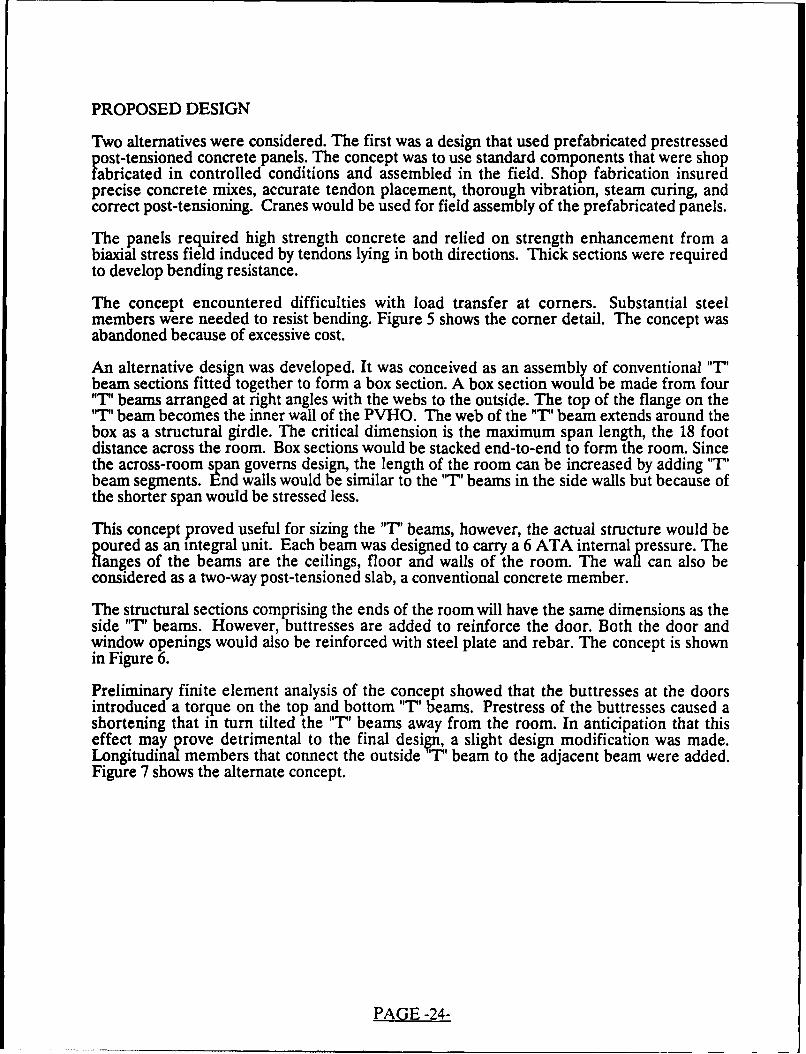
The concept encountered difficulties with load transfer at corners. Substantial steelmembers were needed to resist bending. Figure 5 shows the corner detail. The concept wasabandoned because of excessive cost.
An alternative design was developed. It was conceived as an assembly of conventional "T'beam sections fitted together to form a box section. A box section would be made from four"T" beams arranged at right angles with the webs to the outside. The top of the flange on the"T" beam becomes the inner wall of the PVHO. The web of the "T' beam extends around thebox as a structural girdle. The critical dimension is the maximum span length, the 18 footdistance across the room. Box sections would be stacked end-to-end to form the room. Sincethe across-room span governs design, the length of the room can be increased by adding "T'beam segments. End walls would be similar to the "T' beams in the side walls but because ofthe shorter span would be stressed less.
This concept proved useful for sizing the "T" beams, however, the actual structure would bepoured as an integral unit. Each beam was designed to carry a 6 ATA internal pressure. Theflanges of the beams are the ceilings, floor and walls of the room. The wafl can also beconsidered as a two-way post-tensioned slab, a conventional concrete member.
The structural sections comprising the ends of the room will have the same dimensions as theside "T' beams. However, buttresses are added to reinforce the door. Both the door andwindow openings would also be reinforced with steel plate and rebar. The concept is shownin Figure 6.
Preliminary finite element analysis of the concept showed that the buttresses at the doorsintroduced a torque on the top and bottom "T' beams. Prestress of the buttresses caused ashortening that in turn tilted the "T' beams away from the room. In anticipation that thiseffect may prove detrimental to the final design, a slight design modification was made.Longitudinal members that connect the outside '1" beam to the adjacent beam were added.Figure 7 shows the alternate concept.
PAGE -24-
SEE DETAIL A
FiUE5-P1TESOE1LTSABCNETSOINONRDTI
253

cor.l)
rN
x
Co-
Cl)
I--
r0
0
LUItzC')
LUI
ck:
CD
N
x
26

x
C')
LLJIN-
za I-
e~m
I--
0V)z
0
0LL.
C14x0
27,
PRELIMINARY DESIGN
The preliminary design of the large treatment chamber was made to satisfy ACI ultimatestrength criteria. The 'T' beam was 18 foot long and 6-1/2 foot wide. The live loading wasthe design pressure of 6 ATA or 10,584 psf (pounds per square foot). The assumed concretestrength was 6,000 psi.
The design was checked with a special purpose post-tension computer program (ref. 19). Thedesign was verified both as a post-tensioned 'T' beam and as a post-tensioned flat slab.Reinforcing to produce a balanced design was determined by the computer program.
DETAILED DESIGN
Typically, a preliminary design is made with a number of simplifying assumptions. Thepurpose of the preliminary effort is to size major components. Once sizes are approximated,details are examined more closely. The simplifying assumptions made in the preliminarydesign were:
1. the "T' beam is fixed at the ends. While this assumption is reasonable forpreliminary sizing, the corners are not infinitely rigid and some deflection willoccur. The detailed design examines the biaxial post-tensioning effects onlocal stresses in the corners.
2. the beam has no side restraint. This also is a necessary assumption inherent inmodeling the room as beams. The complementary flat slab preliminarydesign calculations account for the effect of biaxial prestressing of the wallsand acts to confirm the "7' beam design. The preliminary dimensions for themembers are taken as the maximum required to satisfy ACI requirements foreither the "T' beam or the slab.
3. the short span "T' beam represents a worst case for the walls and the ends willbe adequate if the same dimensions are used. This assumption is difficult tojustify since the ends have a large opening for the door and smaller openingsfor the slot windows.
Given these assumptions, confirmatory analysis is needed. The detailed analysis is howeverpreliminary. It also makes simplifying assumptions. The assumptions made are appropriate ina feasibility study, but would require rigorous evaluation in a final design study.
The preliminary design used ultimate strength design principles. Confirmation in thedetailed phase implies a major analytical effort to derive the ultimate burst resistance of theroom. Such is beyond the scope of this feasibility study. The alternative elastic strengthdesign method is more amenable to finite element analysis. It is used in the following. Notehowever that some differences may develop as the two design methodologies are notnecessarily consistent.
The detailed design is directed at a number of issues. Confirmation of gross dimensions isdesired. Insight into how the room deflects under no load and design pressure is valuable.The stresses at the intersection of the "T' beams needs definition. Deflection, load transferand stresses at the end to ceiling location is of particular interest as it may force the alternatedesign, Figure 7, to be used. Finally nominal stresses in the inside corners and aroundopenings is useful in confirming the adequacy of the proposed design.
PAGE -28-
FINITE ELEMENT ANALYSIS OF THE MAIN TREATMENT CHAMBER
There is considerable interest in the techniques used for modeling of concrete structures(ref. 20). Research is directed at sophisticated material models and solution algorithms thatcan account for the creep, cracking and crushing in concrete and the relaxation and yieldingof tendon strands. However, in this study, the finite element method (FEM) is confined to alinear static analysis. This simplification is consistent with the elastic strength method of theACI Code. The ANSYS finite element program is used (ref. 21).
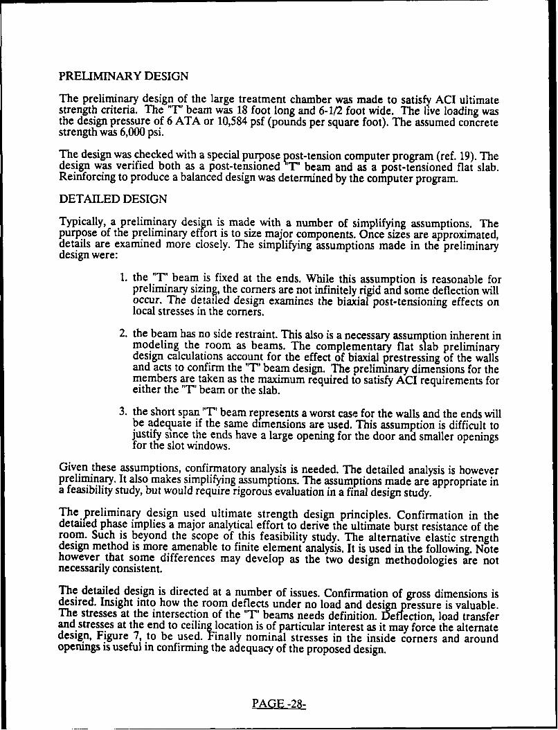
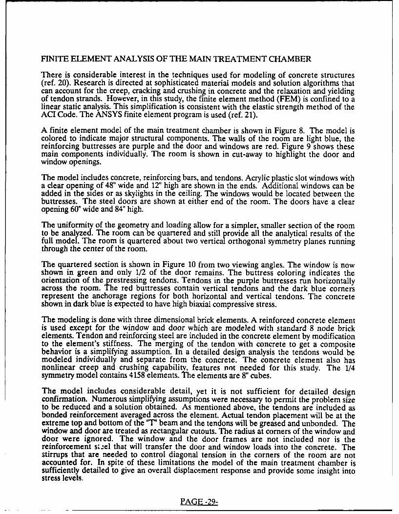
A finite element model of the main treatment chamber is shown in Figure 8. The model iscolored to indicate major structural components. The walls of the room are light blue, thereinforcing buttresses are purple and the door and windows are red. Figure 9 shows thesemain components individually. The room is shown in cut-away to highlight the door andwindow openings.
The model includes concrete, reinforcing bars, and tendons. Acrylic plastic slot windows witha clear opening of 48" wide and 12" high are shown in the ends. Additional windows can beadded in the sides or as skylights in the ceiling. The windows would be located between thebuttresses. The steel doors are shown at either end of the room. The doors have a clearopening 60" wide and 84" high.
The uniformity of the geometry and loading allow for a simpler, smaller section of the roomto be analyzed. The room can be quartered and still provide all the analytical results of thefull model. The room is quartered about two vertical orthogonal symmetry planes runningthrough the center of the room.
The quartered section is shown in Figure 10 from two viewing angles. The window is nowshown in green and only 1/2 of the door remains. The buttress coloring indicates theorientation of the prestressing tendons. Tendons in the purple buttresses run horizontallyacross the room. The red buttresses contain vertical tendons and the dark blue comersrepresent the anchorage regions for both horizontal and vertical tendons. The concreteshown in dark blue is expected to have high biaxial compressive stress.
The modeling is done with three dimensional brick elements. A reinforced concrete elementis used except for the window and door which are modeled with standard 8 node brickelements. Tendon and reinforcing steel are included in the concrete element by modificationto the element's stiffness. The merging of the tendon with concrete to get a compositebehavior is a simplifying assumption. In a detailed design analysis the tendons would bemodeled individually and separate from the concrete. The concrete element also hasnonlinear creep and crushing capability, features not needed for this study. The 1/4symmetry model contains 4158 elements. The elements are 8" cubes.
The model includes considerable detail, yet it is not sufficient for detailed designconfirmation. Numerous simplifying assumptions were necessary to permit the problem sizeto be reduced and a solution obtained. As mentioned above, the tendons are included asbonded reinforcement averaged across the element. Actual tendon placement will be at theextreme top and bottom of the "T" beam and the tendons will be greased and unbonded. Thewindow and door are treated as rectangular cutouts. The radius at comers of the window anddoor were ignored. The window and the door frames are not included nor is thereinforcement steel that will transfer the door and window loads into the concrete. Thestirrups that are needed to control diagonal tension in the corners of the room are notaccounted for. In spite of these limitations the model of the main treatment chamber issufficiently detailed to give an overall displacement response and provide some insight intostress levels.
PAGE -29-
E
4-1c
E0
4-d
m
1.4m
€0
E
01
m
+A
°c
30
ML 0
0
cc1
.4d
.4
31-

41'
0
4
32a
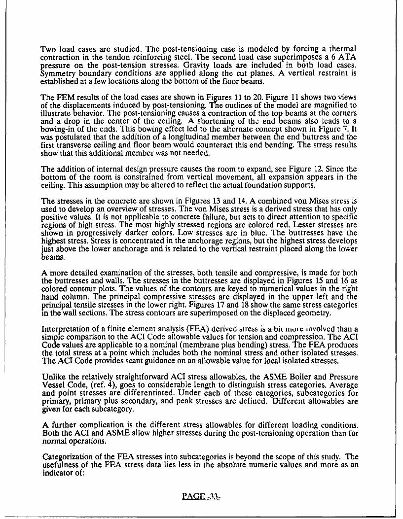
Two load cases are studied. The post-tensioning case is modeled by forcing a thermalcontraction in the tendon reinforcing steel. The second load case superimposes a 6 ATApressure on the post-tension stresses. Gravity loads are included in both load cases.Symmetry boundary conditions are applied along the cut planes. A vertical restraint isestablished at a few locations along the bottom of the floor beams.
The FEM results of the load cases are shown in Figures 11 to 20. Figure 11 shows two viewsof the displacements induced by post-tensioning. The outlines of the model are magnified toillustrate behavior. The post-ten-sioning causes a contraction of the top beams at the cornersand a drop in the center of the ceiling. A shortening of th2 end beams also leads to abowing-in of the ends. This bowing effect led to the alternate concept shown in Figure 7. Itwas postulated that the addition of a longitudinal member between the end buttress and thefirst transverse ceiling and floor beam would counteract this end bending. The stress resultsshow that this additional member was not needed.
The addition of internal design pressure causes the room to expand, see Figure 12. Since thebottom of the room is constrained from vertical movement, all expansion appears in theceiling. This assumption may be altered to reflect the actual foundation supports.
The stresses in the concrete are shown in Figures 13 and 14. A combined von Mises stress isused to develop an overview of stresses. The von Mises stress is a derived stress that has onlypositive values. It is not applicable to concrete failure, but acts to direct attention to specificregions of high stress. The most highly stressed regions are colored red. Lesser stresses areshown in progressively darker colors. Low stresses are in blue. The buttresses have thehighest stress. Stress is concentrated in the anchorage regions, but the highest stress developsjust above the lower anchorage and is related to the vertical restraint placed along the lowerbeams.
A more detailed examination of the stresses, both tensile and compressive, is made for boththe buttresses and walls. The stresses in the buttresses are displayed in Figures 15 and 16 ascolored contour plots. The values of the contours are keyed to numerical values in the righthand column. The principal compressive stresses are displayed in the upper left and theprincipal tensile stresses in the lower right. Figures 17 and 18 show the same stress categoriesin the wall sections. The stress contours are superimposed on the displaced geometry.
Interpretation of a finite element analysis (FEA) derived btrebs is it biL Ihore involved than asimple comparison to the ACI Code allowable values for tension and compression. The ACICode values are applicable to a nominal (membrane plus bending) stress. The FEA producesthe total stress at a point which includes both the nominal stress and other isolated stresses.The ACI Code provides scant guidance on an allowable value for local isolated stresses.
Unlike the relatively straightforward ACI stress allowables, the ASME Boiler and PressureVessel Code, (ref. 4), goes to considerable length to distinguish stress categories. Averageand point stresses are differentiated. Under each of these categories, sub categories forprimary, primary plus secondary, and peak stresses are defined. Different allowables aregiven for each subcategory.
A further complication is the different stress allowables for different loading conditions.Both the ACI and ASME allow higher stresses during the post-tensioning operation than fornormal operations.
Categorization of the FEA stresses into subcategories is beyond the scope of this study. Theusefulness of the FEA stress data lies less in the absolute numeric values and more as anindicator of:
PAGE -33-

WLAm
L)
Vdoc
0
W L06th
cdo
mP-4
34

mL)
Alkcc1-4cc
ca
m
4dA A A.I. f m11 ali Pt I JL-
CL0
V-v
A-ACL
AAI 1
t uzm V Nwe
cn.P.4
35

a,
.)
410
0
.
E'U
Cn
36

C')
4.'
P-4
5-1
CL
t"
4d
0
IP4
37

1. the general stress condition in the chamber,
2. regions of local stress concentration,
3. the distribution of load in and between the buttresses and walls, and
4. when compared to allowable values from the ACI or ASME Code, as ameasure of design adequacy.
The ACI Code concrete strength allowables are given in Table 2 for three concrete strengthsand two loading conditions. The operating condition membrane plus bending stressallowables for concrete are [0.45 * f c] for compression and [6 * sqrt(f'c)] in tension. In localregions the tensile stress may be increased by a factor of 2. During post-tensioning, the ACICode permits concrete compressive stress to be as high as [0.6 * fc].
TABLE 2 - ALLOWABLE CONCRETE STRESSES
Concrete Strength 6,000 psi 12,000 psi 18,000 psi
Operating Compressive 2700 psi 5400 psi 8100 psi
Post-Tension Compressive 3600 psi 7200 psi 10800 psi
Average Tensile 465 psi 657 psi 805 psi
Local Tensile 930 psi 1314 psi 1610 psi
ACI Elastic Modulus 4,696 ksi 6,641 ksi 8,134 ksi
------------------------------------------ ---------------
The contours displayed on Figure 15 through 18 represent the allowable concrete stresses in6000 psi concrete. The green shades are for regions where the compressive stress does notexceed the operating compressive allowable of 2700 psi. The higher compressive limitpermitted during post-tensioning is shown as light blue. Yellow regions have tensile stressthat is less than the 465 psi tensile limit. Local tensile limits are indicated with red. Darkershades of blue show regions of compressive stress beyond the ACI Code limits.
Figure 15 shows that the compressive prestress is concentrated in the corners and in theceiling beams. High compression is expected at the comers where vertical and horizontaltendons meet. The higher prestress in the ceiling beams was applied to counteract the largebending effect of internal pressure. The tensile stresses are shown to the lower right. Theprestress in the ceiling beams causes a tensile stress to develop on the outside of the verticalside wall buttresses.
The application of internal pressure, Figure 16, increases the region of tensile stress on thesebuttresses. The internal pressure also produces tensile stress in the extreme fibers of thetransverse ceiling and floor beams. The selection of preload in these members will requirecare to insure an acceptable stress level. It is noted again that the FEM model averaged the
PAGE -&-

tendons across the concrete section and a more exact treatment that places tendons near theextreme fibres may produce lower tensile stress in the concrete.
The wall stresses, shown in Figures 17 and 18, are within ACI Code allowables. The onlyregions that show tension are around the door and at the inside corners. Localsteel rebar reinforcement would be provided in these regions.
Tendon strains and stresses are illustrated in Figures 19 and 20. The ACI Code allowable fortendons during prestress is 85% of the tendon tensile strength. It is expected that tendonstress will diminish by about 20% as a result of creep and shrinkage in the concrete andrelaxation in the tendons. For a 270 ksi tendon, the allowable stress during post-tensioning is230 ksi. The tendon stresses do not exceed the Code allowables, however, an interpretationthat tendon stresses are acceptable must be deferred to the final detailed design.
The FEA analysis confirms the feasibility of the proposed design for the main treatmentchamber. A cost estimate can be prepared using the preliminary design sizes and materialvolumes. Additional analysis is needed to develop a detailed design.
PAGE -39-

III I IlmvcrIi. 511
w'0'
0
rowi
40d

EERIE WII I II I ovoA
C,
Go0
to
do4A
LAa
4d
4
.P4
41
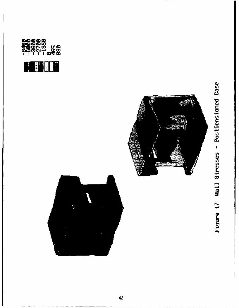
wwmcww J1
Go
+A*0*0-
N
(U
42

lowN~ Is lm
I I I I I Wqc
1MM10I WIW
0
CcCc
P-4
54-
P.4
43J

NNNNNNNNCO C NNWwwU1NOwWCww
101010w404040... * * .... *
DOI 'JAION
I.E I~WI I WIUU H
*64
4Fi

. . . . . . .a),-cmomawmvqo
CDNNNNOO0000 NO~0NCO~cc
I-
C
Cdo
I.4
45

FINITE ELEMENT ANALYSIS OF SLOT WINDOW
An unconventional slot-shaped PVHO window is proposed. Windows in medical PVHOchambers are circular and made from acrylic plastic. The PVHO Code has rules for thedesign of flat circular or disk windows; however flat rectangular windows are not covered.
The circular window is not the ideal shape for a rectangular concrete room. The desirableshape is a long window located at eye height. A long window permits the observer to view thechamber by rotating rather than moving the head. Multiple circular windows must be placedside to side to achieve a panoramic view of the patients. Multiple windows in close proximitymay pose structural design problems.
The proposed window for a rectangular concrete PVHO is rectangular with rounded ends.The window is 15" wide by 48" long with a clear viewing area of 12" wide by 45" long. Theends are semi circular. This slot window is not a PVHO Code approved design.
The PVHO rules require an extensive test program for new window designs. Five short termfailure tests, 5 long term creep tests, and 2 fatigue tests must be performed. Currently thereare no rules for windows to be designed by finite element analysis. The PVHO rules arebased upon empirical test data. The conventional practice for design of acrylic windowsaccounts for the viscoelastic and creep effects in acrylic through a "Conversion Factor". ThePVHO conversion factor varies with window shape, design pressure and operatingtemperature. Factors range from a low of 4 to a high of 25. The conversion factor isessentially a safety factor on tensile stress. Attempts to correlate the experimental data toanalytical predictions have not been successful; however, there is a recognized need for adesign anlysis option to the expensive experimental program. One approach that develops a"pseudo-allowable" design stress is described.
Assuming that the conversion factor is a safety factor, then a design allowable stress can befound and this stress used for comparison to stresses found from a FEM analysis. G;"en thePVHO minimum tensile stress of 9000 psi and the conversion factor of 8 for a flat window at< 100 degrees F, a pseudo-allowable stress for acrylic windows is 1,125 psi.
The thickness of the slot window will be confirmed with a FEM analysis, but a preliminarythickness must be specified. In addition to the structural consideration, window thicknessshould not exceed 4' thick. Acrylic sheet is available to 4" thickness and while thicker sectionscan be cast, quality control is more difficult and costs escalate. The initial window thickness istherefore 4".
The FEM model for the 4" thick slot window is shown in Figure 21. It consists of 936 threedimensional solid elements. A line support is assumed 1.5" from the edge running completelyaround the window. The resulting 12" wide by 45" length opening is loaded with a 6 ATApressure. The bottom view on Figure 21 illustrates these conditions. Pressure is red anddisplacement constraints are blue.
The FEM results are shown in Figure 22. Von Mises effective stresses are displayed andreferenced in the color key to the right. The maximum stress develops at the center of thewindow. The maximum stress of 694 psi is less than the pseudo-allowable of 1125 psi. Whilethe FEM analysis predicts an acceptable slot window design, experimental confirmation inaccordance with the PVHO rules is required.
PAGE -46-

0
r I
,--L L- L
Lt
LLLLLLJ
cn
711
47
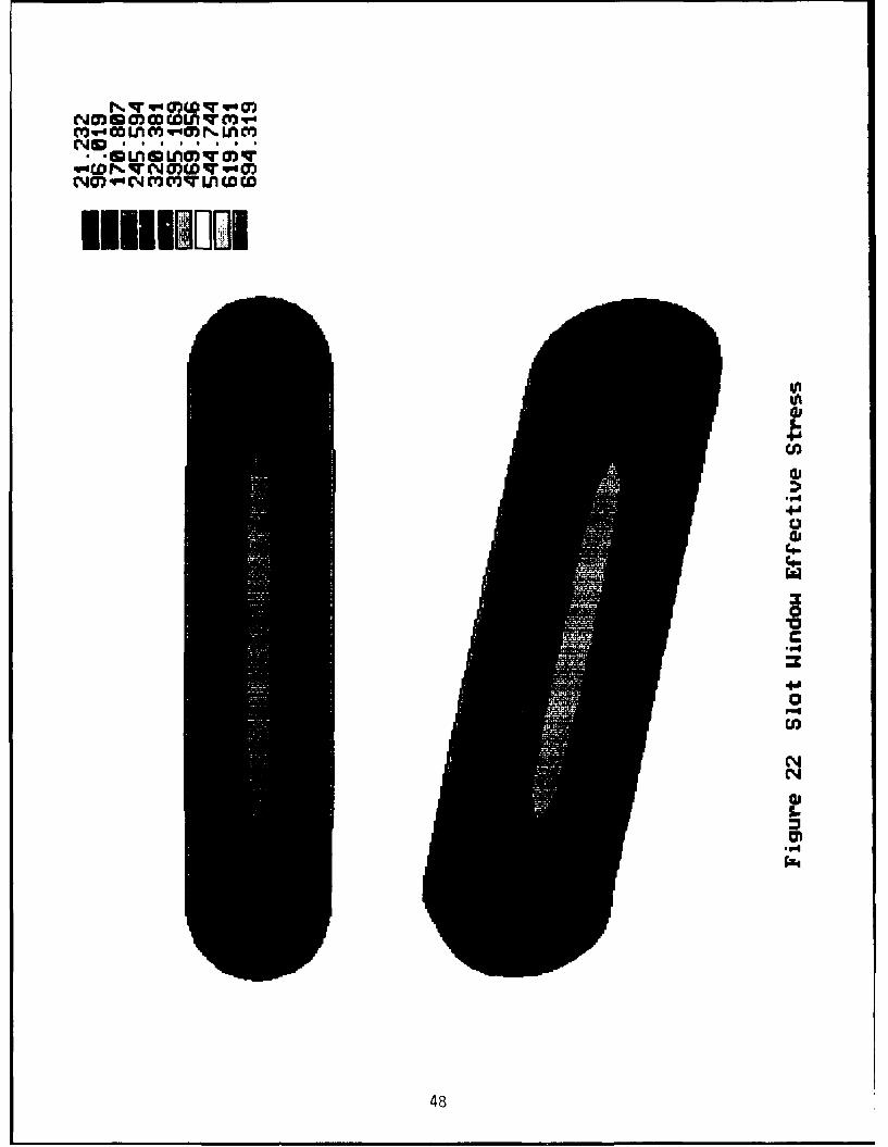
q~do(V~q-t
(%J ~. . . .S SD
4a
04
.40.
484

FINITE ELEMENT ANALYSIS OF RECTANGULAR DOOR
Rectangular doors are specified for most medical multiplace PVHOs. The door is sized toseal a rectangular opening of about 32" wide by 72" high. The doors also have a circularwindow located at eye level. A common practice is to specify :he dnor thickness at twice theASME Code design thickness so that the window opening requires no added reinforcing.This approach which is dictated by costs, yields very heavy doors.
Numerous FEM studies have shown that corner stresses in the mating door frame can becontrolled by adding a comer radius of 3"-4". These studies have also revealed that the doormakes contact along the edges except at the corners where it moves away from the frame.
The door desired for the concrete PVHO was larger than any specified for a PVHO. A 60"wide by 84" high opening would improve patient movement and was considered a necessity.The window in the door was specified at 24" clear opening.
The door was designed using the ASME rules for flat rectangular openings. The minimumthickness was calculated to be 2-3/4". If the door thickness were doubled to make the windowopening self reinforcing, the door would weigh 5 tons. The door thickness is maintained atASME Code limits and the window is reinforced locally.
The FEM model of the door is shown in Figure 23. The window, shown in purple is 4" thick.The 6" thick window reinforcing is shown red. A plate model consisting of 820 elements isloaded with 6 ATA pressure. The edges are restrained in the plane of the model except atthe 6" radius comers.
Stresses are shown in Figure 24. The contours to the right are top for the door steel andbottom for the acrylic window. ASME Code allowable stress is 17,500 psi. The door meetsthis requirement. The maximum stress in the acrylic window is 519 psi, also well below thepseudo-allowable stress of 1125 psi.
PAGE -49-

0
N
.C-
I
.0
CY-C14
5-
500

0)0
CW)W~N NO)WCDO
C~mW~-'C\CO~ N 0)0))0)0
U NIF
4- 4-v
In.;In
51-

COST
A prime objective of this study was to compare the cost of a concrete rectangular room tocost of a conventional steel PVHO. To compare concrete to steel, a base line concretedesign was needed. A post-tensioned concrete room 27 foot long, 18 foot wide and 10 foothigh was the base line chosen. This room configuration, shown in Figure 6, has beendesigned to the ACI Code and the design confirmed by finite element analysis.
The unit cost for conventional 6,000 psi post-tensioned concrete is $300 to $400/cu.yd.installed. Higher strength concrete is more costly. Relative concrete costs were reported in1986 for a Chicago high rise. The costs are for concrete only.
Cost for: 6 ksi was $ 58.81 cu.yd. or $9.8 / cu.yd. / ksi, and
14 ksi was $145.33 cu.yd. or $10.4 / cu.yd. / ksi.
This data suggests that concrete cost is proportional to strength. In Seattle, high strengthconcrete cost 3 times conventional strength, but the high strength, 19,000 psi was about 3times as strong as conventional concrete. Based upon these data, the cost of concrete isapproximately proportional to strength.
High strength concrete cos..s more per cubic yard but the reduction in the size of membersmay be offsetting. In an attempt to uncover the cost sensitivity of higher strength concrete, apreliminary design of three different room geometries using three concrete strengths wasdone. The basic variable in room geometry was the spacing between buttresses. The basedesign used a 6-1/2 foot spacing. If one buttress was removed, the spacing would be increasedto 8-1/2 foot. An intermediate spacing of 7-1/2 foot was also calculated as representative oflonger rooms. Concrete strengths investigated were 6,000 psi, 12,000 psi and 18,000 psi.Concrete costs were assumed proportional to strength.
The summary of costs is given in Table 3. The details of the cost analysis are in Appendix A.
TABLE 3 CONCRETE RECTANGULAR PVHO COSTS
Span (ft) 6 ksi 12 ksi 18 ksi
($300/yd) ($600/yd) ($1200/yd)
6.5 $46,135 $80,683 $151,532
7.5 $45,402 $78,832 $147,588
8.5 $44,891 $77,615 $144,715
The cost data clearly indicate that the design is not sensitive to span length, but is stronglydependent on concrete strength. The higher the strength the greater the cost. Closerexamination of the individual designs showed that the controlling factor was the allowabletensile strength of the concrete. Unfortunately the value of increased compressive strength isnot fully appreciated in a tensile strength increase. The ACI Code gives credit for increasesin tensile strength as the square root of compressive strength, not in proportion tocompressive strength.
PAGE -52-

The least expensive alternative is the longer span in low strength concrete. However, theconclusion that the 8-1/2 foot span is best, needs further study. The cost sensitivity study wasan exercise that assumed reinforcing requirements of the ACI Code could be accommodatedin the beam sections used. The only design that received careful review was the 6-1/2 footspan of the proposed design. Since the cost differential between the different span widths issmall and the details of the shorter span has been carefully checked, the 6-1/2 foot span isselected as the preferred design.
The selection of conventional strength concrete accrues side benefits. At lower strengths alarge tolerance on mix design can be accommodated. The availability of competent localproducers is increased. Also, the hospital contractor will have familiarity with placementproblems.
The total estimated cost for rectangular concrete 6 ATA PVHO is $200,000. The mainchamber will cost $50,000, eight windows at $6,000 each will add another $50,000, the doors(2) are estimated to cost $50,000 and $50,000 is included for other structural details. Notethat the concrete room accounts for only 25% of the estimated cost.
The total structural cost for a three chamber complex is developed from the assumption thatcosts are proportional to length and that the chambers can be constructed in tandem, seeFigure 3. A 45 foot total length is assumed for the three chamber complex. The structuralcost for a PVHO rectangular room complex comparable in size and functionality to a steelCHF is $350,000.
The cost of large medical PVHO steel vessels is known. The vessel costs alone in the firstUSAF HBO at Wright Patterson, the WPCHF, was more than $1,350,000. The secondPVHO at Travis AFB and the DGCHF vessels cost $1,600,000. The projected cost for thePortsmouth Naval Hospital PVHO chambers is also $1,600,000. For comparison, the currentprice for a commercial multiplace PVHO is about $10 per pound of steel.
The concrete CHF at an estimated cost of $350,000 compares favorably to steel at$1,600,000. Concrete is 22% the cost of steel. This is in the range of 70% cost savings foundin other studies of concrete versus steel.
A number of potential cost risers exist, however. The concrete room will be first of a kindand start up problems need to be allowed for. The installation of the stainless steel lining andits use as a concrete form could pose difficulties, particularly with the floor.
A major expense will be the detailed design of the first rectangular concrete PVHO. TheACI ultimate strength method used in the feasibility study will probably require experimentalor analytical confirmation. Experimental confirmation makes some sense considering therelatively low cost of a concrete PVHO. A more credible scenario would have theexperimental program follow a detailed design study using finite element analysis and theelastic strength rules of ASME, Section III, Division 2. The ASME rules have been inexistence for more than 15 years, but have been applied in relatively few instances. The costof familiarization of civil structural designers to the ASME rules may increase the detaileddesign cost a significant amount. The detailed design of the first rectangular concrete PVHOcould be as much as $150,000.
A counteracting factor is the potential to reuse this detailed design on successive PVHOs.The feasibility study showed that the room can be expanded to meet specific sizerequirements. If the width of the room is held constant, length can be varied without majordesign impact. Accordingly, a generic design for concrete PVHOs can be developed,
PAGE -53-
thoroughly analyzed, possibly built and tested as a prototype and then applied to subsequenthospital installations. Amortization of design, development and testing costs across two orthree facilities would make the cost comparison even more attractive. The experimentalprogram leading to certification of the slot window will be costly. A prototype window isestimated to cost $25,000. Subsequent windows will cost less, but the experimental effortcould be as much as $100,000.
The large door may prove more costly than estimated. It too is a new door design. Thestructural design is straight forward and is based on considerable experience and success.FEM is well suited for design optimization and a cost tradeoff of conventional uniformthickness versus local reinforcement should be made. The mechanical design of the door isless obvious and may increase costs. A sliding door appears a logical choice with supportprovided from the floor or hung from the ceiling. A sliding door gives excellent spaceutilization but will require a mechanical assist. Sealing of the door may prove difficult.
The QA awareness of hospital contractor may lead to increased cost. If the contractor seesQA as a risk, due to lack of familiarity, price will rise. An associated QA cost is the effortrequired for first of the kind Code approval. The first RPC/PVHO (RectangularPost-tensioned Concrete Pressure Vessel for Human Occupancy) will require ASME PVHO,ACI, the local jurisdiction building inspectors, and possibly the ASME Boiler and PressureVessel Code Nuclear Certification groups concurrence.
PAGE -54-

CODE COMPLIANCE
The primary group responsible for codification of rules for design certification of medicalHBO systems is the ASME Committee for Pressure Vessels for Human Occupancy (PVHO).The PVHO rules, (ref. 2), were developed as an industry consensus standard. The rules havebeen adopted by the US Coast Guard, the US Navy and the US Air Force as minimumrequirements for the design, fabrication and testing of PVHO chambers. PVHO-1 is alsorecognized by the National Board of Boiler and Pressure Vessel Inspectors and local, stateand international regulatory groups. Users of all recent commercial PVHO vessels invokePVHO-1 in their purchase specifications.
Industry acceptance of prestressed concrete for PVHO rectangular chambers will follow onlyafter the rules of PVHO-1 are revised to include concrete as an approved material ofconstruction. Rule changes are made to PVHO-1 through either of two techniques. If anexisting safety standard covers all or part of the special requirements of PVHO, the standardcan be adopted by reference. This is the method used to include rules of the ASME Boilerand Pressure Vessel Code, Section VIII, and ANSI B31.1 for piping. If the special needs ofPVHO have not been developed by other standards, then a development effort is begunwithin the PVHO Committee. This latter approach led to the acrylic window rules nowwidely referenced throughout the world, and the special provisions for design of spheresexposed to external pressure.
Two industry standards organizations are involved with safety standards for prestressedconcrete construction; the American Concrete Institute (ACI), and the ASME Section III,Division 2 subcommittee. The ACI develops rules that are adopted as the Uniform BuildingCode and are applied to buildings, bridges and other prestressed concrete civil engineeringstructures. The ACI Code is widely known and is familiar to hospital building contractors.Unfortunately it is not specifically developed for pressure vessels and as a commercial code itdoes not have a rigorous QA plan to guarantee quality.
The ASME Code is much better suited for pressure vessels constructed of prestressedconcrete than the ACI building code. The ASME and the ACI formed a joint working groupto develop rules for concrete nuclear pressure vessels in the early 1970's. That groupcontinues today, albeit at a low level of activity. The ASME Section III, Division 2 (ref. 4)offers rules that are directed specifically to post-tensioned concrete pressure vessels. Therules were written for nuclear reactor vessels and accordingly insure a high degree of safety.While increased safety is desirable, it results in increased design analysis, paperwork andcost. In spite of these potential difficulties, the application of the ASME rules is the mostdirect means for adoption of prestressed concrete into the PVHO-1.
The ASME rules for concrete nuclear reactor vessels distinguish two categories; for reactorvessels, (Section CB) and for containment, (Section CC). The reactor vessels are exposed tohigh internal operating pressures, high temperatures and intense radiation. The containmentvessels surround the reactor vessels and provide backup low pressure resistance in the eventthe reactor fails. The containment vessels are buildings and are designed using variants to theACI Code requirements. The containment vessel is designed using the ACI concepts of loadfactors and ultimate strength.
The reactor vessels are designed using the elastic response method. The reactor vessel isrequired to operate in the elastic portion of the stress-strain curve. Furthermore, the vesselmust demonstrate a "gradual, observable and predictable response to overload". Theultimate capacity of the concrete pressure vessel must be at least twice the maximumpressure. The finite element method is used to validate the reactor vessel design.
PAGE -55-

The reactor design method is consistent with current practice for PVHOs. The designmethods are well established and familiar to the PVHO Committee and the ASMEstandards organization. Acceptance of this technology is therefore expected. Accordingly,the ASME Section III, Division 2, Subsection CB rules are recommended for adoption byPVHO-I and will in turn become the basis for acceptance of rectangular post-tensionedconcrete pressure vessels for medical HBO therapy.
PAGE-56-

CONCLUSIONS
1. Post-tensioned concrete for large multiplace PVHO's is economical and costs about 1/4that of an equivalent steel chamber. Moderate strength concrete of 6,000 psi compressivestrength is the optimum and higher strength concrete up to 18,000 psi offers little reductionin member size. Rectangular concrete vessel design is controlled by the allowable tensilestrength of concrete. Concrete cost is proportional to strength.
2. A rectangular room configuration is practical for concrete PVHOs. Rectangular rooms canbe readily expanded to larger sizes. The proposed design is not sensitive to length.Intermediate walls permit segmenting a large rectangular pressure vessel into multiplerooms.
3. Slot windows can be designed with stresses that are low enough to gain PVHO acceptance.Experimental studies will be needed to confirm the slot window design.
4. Large rectangular doors are feasible and adapt well to rectangular rooms. A door five footwide and seven foot high poses no special structural problems. Mechanical problems withactuation and sealing need careful attention during final detailed design.
5. Incorporation of the ASME Boiler and Pressure Vessel Code, Section III,Division 2, Subsection CB rules into PVHO-1 will provide a sound technical basis forpost-tensioned concrete as a construction material for rectangular HBO therapy chambers.
PAGE -57-

REFERENCES
1. Section VIII Rules for Construction of Pressure Vessels. Division 1, ASME, 1989 Editionwith Addenda.
2. Safety Standard for Pressure Vessels for Human Occupancy, ASME/ANSI PVHO-1-1987,American Society of Mechanical Engineers, New York, 1987.
3. Herbaric Oxygen Therapy Ed. by J.C. Davis and T.K. Hunt, Undersea Medical Society,1977, Chapter 4.
4. Section III Rules for Construction of Nuclear Power Plant Components. Division 2 Codefor Concrete Reactor Vessels and Containment, (ACI Standard 359-89), ASME, 1989Edition with Addenda.
5. J.R. Maison, "Large High Pressure Vessels for Simulating the Deep Ocean", NCEL TR794, July, 1979.
6. T.Y. Lin Inc., "Feasibility Study for Prestressed Concrete Pressure Vessles", NAVFACContract Report N0025-79-6-0012, May 1980.
7. "Composite Concrete and Steel High Pressure Vessels for General Industrial Use", ACI36-R-86, American Concrete Institute, Apr 86.
8. Sheffield, P.J. et al, "Fabrication and Design Considerations for a Multiplace ClinicalHyperbaric Facility", USAFSAM-TR-77-7, Mar 1977.
9. Workman, W.T., et aA, "Medical Planning Criteria for Implementation of ClinicalHyperbaric Facilities", USAFSAM-TR-84-36, Dec 1984.10. New Horizons in Construction Materials, Ed. by D.Y. Lee and S.P. Shah, AmericanSociety of Civil Engineers, Oct. 88.
11. ACI 1983 Building Code, American Concrete Institute, ACI 381-83, 1983.
12. High Strength Concrete, Ed. by H.G. Russel, ACI-87, 1985.
13. Design of Prestressed Concrete Structures, Third Edition, T.Y. Lin and N.H. Bums,Wiley, 1981.
14. PCI Design Handbook. Precast and Prestressed Concrete, 3rd Edition, 1985, PrestressedConcrete Institute, 201 North Wells St, Chicago.
15. Structural Guide to the ACI Building Code. Third Edition, P.F. Rice, et.al., VanNostrand, 1985.
16. "Considerations for Design of Concrerte Structures Subjected to Fa*igue Loading", ACICommittee Report ACI215R-86, 1986.
17. Concrete Problems Causes and Cures, J.C. Ropke, McGraw Hill, 1982.
18. In Situ Nondestructive Testing of Concrete, Ed by V.M. Malhotra, ACI SP-82, 1984.
19. Computer Program "P/T DATA", developed by Structural Data Inc., Fountain Valley,
PAGE -58-

CA.
20. Finite Element Analysis of Reinforced Concrete Structures, Ed. by C. Meyer and H.Okamura, ASCE Seminar Proceedings, May 1985.
21. ANSYS Engineering Analysis System User's Manual - Revision 4.4, G.J. DeSalvo andR.W. Gorman, Swanson Analysis Systems, Houston, PA, 1989.
PAGE -

APPENDIX A. DETAILED COST BREAKOUT
RECTANGULAR CONCRETE PVHO COST ANALYSIS for 6,000 PSI CONCRETE
6.5 ft Span - 6000 psi
Total Cost $46,135
lbs/ft feet Total Cost/# Total $ $ %weight
Floor Beam 34519 $3,249Concrete 1491 22 32802 $0.0741 $2,430 75%Tendons 312 $1.5000 $468 14%Rebars 1405 $0.2500 $351 11%
Roof Beam 31721 $3,019Concrete 1366 22 30052 $0.0741 $2,226 74%Tendons 300 $1.5000 $450 15%Rebars 1369 $0.2500 $342 11%
Side Beam 13454 $1,175Concrete 1291 10 12910 $0.0741 $956 81%Tendons 66 $1.5000 $99 8%Rebars 478 $0.2500 $119 10%
7.5 ft Span - 6000 psi
Total Cost $45,402
lbs/ft feet Total Cost/# Total $ $ %weight
Floor Beam 38931 $3,712Concrete 1675 22 36850 $0.0741 $2,730 74%Tendons 370 $1.5000 $554 15%Rebars 1712 $0.2500 $428 12%
Roof Beam 35673 $3,452Concrete 1528 22 33616 $0.0741 $2,490 72%Tendons 358 $1.5000 $537 16%Rebars 1699 $0.2500 $425 12%
Side Beam 15407 $1,358Concrete 1475 10 14750 $0.0741 $1,093 80%Tendons 81 $1.5000 $121 9%Rebars 576 $0.2500 $144 11%
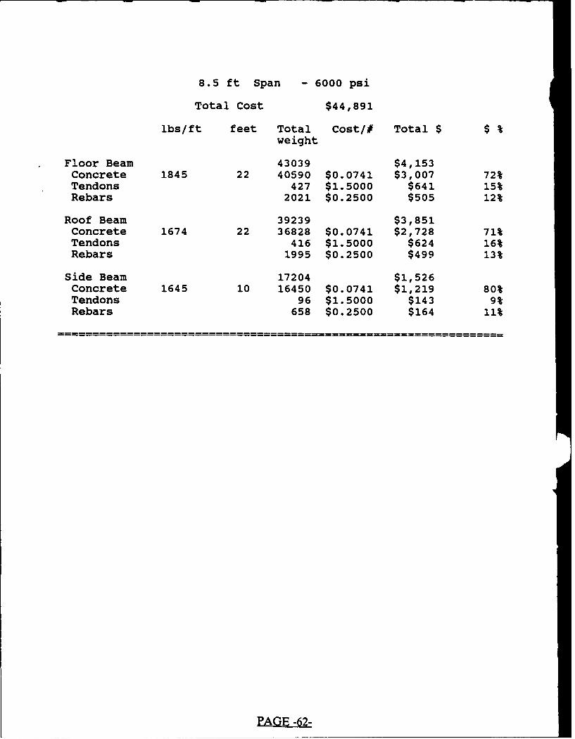
8.5 ft Span - 6000 psi
Total Cost $44,891
lbs/ft feet Total Cost/# Total $ $ %weight
Floor Beam 43039 $4,153Concrete 1845 22 40590 $0.0741 $3,007 72%Tendons 427 $1.5000 $641 15%Rebars 2021 $0.2500 $505 12%
Roof Beam 39239 $3,851Concrete 1674 22 36828 $0.0741 $2,728 71%Tendons 416 $1.5000 $624 16%Rebars 1995 $0.2500 $499 13%
Side Beam 17204 $1,526Concrete 1645 10 16450 $0.0741 $1,219 80%Tendons 96 $1.5000 $143 9%Rebars 658 $0.2500 $164 11%
EA~14
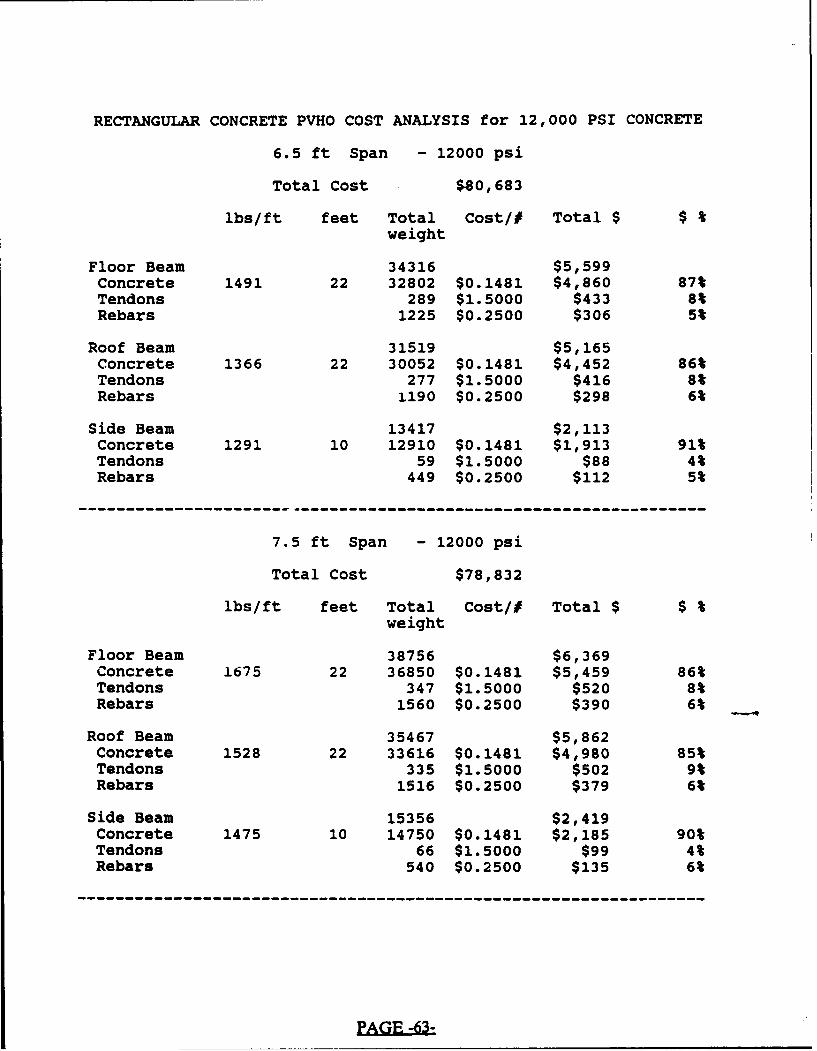
RECTANGULAR CONCRETE PVHO COST ANALYSIS for 12,000 PSI CONCRETE
6.5 ft Span - 12000 psi
Total Cost $80,683
lbs/ft feet Total Cost/# Total $ $ %weight
Floor Beam 34316 $5,599Concrete 1491 22 32802 $0.1481 $4,860 87%Tendons 289 $1.5000 $433 8%Rebars 1225 $0.2500 $306 5%
Roof Beam 31519 $5,165Concrete 1366 22 30052 $0.1481 $4,452 86%Tendons 277 $1.5000 $416 8%Rebars 1190 $0.2500 $298 6%
Side Beam 13417 $2,113Concrete 1291 10 12910 $0.1481 $1,913 91%Tendons 59 $1.5000 $88 4%Rebars 449 $0.2500 $112 5%
7.5 ft Span - 12000 psi
Total Cost $78,832
lbs/ft feet Total Cost/# Total $ $ %weight
Floor Beam 38756 $6,369Concrete 1675 22 36850 $0.1481 $5,459 86%Tendons 347 $1.5000 $520 8%Rebars 1560 $0.2500 $390 6%
Roof Beam 35467 $5,862Concrete 1528 22 33616 $0.1481 $4,980 85%Tendons 335 $1.5000 $502 9%Rebars 1516 $0.2500 $379 6%
Side Beam 15356 $2,419Concrete 1475 10 14750 $0.1481 $2,185 90%Tendons 66 $1.5000 $99 4%Rebars 540 $0.2500 $135 6%
------ -- - -- - -- - -- - -- - -- - -- - -- - -- - -- - -- -


8.5 ft Span - 12000 psi
Total Cost $77,615
lbs/ft feet Total Cost/# Total $ $ %weight -
Floor Beam 42834 $7,079Concrete 1845 22 40590 $0.1481 $6,013 85%Tendons 404 $1.5000 $606 9%Rebars 1839 $0.2500 $460 6%
Roof Beam 39C.6 $6,501Concrete 1674 22 36828 $0.1481 $5,456 84%Tendons 393 $1.5000 $589 9%Rebars 1826 $0.2500 $456 7%
Side Beam 17157 $2,715Concrete 1645 10 16450 $0.1481 $2,437 90%Tendons 81 $1.5000 $121 4%Rebars 626 $0.2500 $157 6%
PAE -64-

RECTANGULAR CONCRETE PVHO COST ANALYSIS for 18,000 PSI CONCRETE
6.5 ft Span - 18,000 psi
Total Cost $151,532
lbs/ft feet Total Cost/# Total $ $ %weight
Floor Beam 34444 $10,476Concrete 1491 22 32802 $0.2963 $9,719 93%Tendons 277 $1.5000 $416 4%Rebars 1364 $0.2500 $341 3%
Roof Beam 31658 $9,633Concrete 1366 22 30052 $0.2963 $8,904 92%Tendons 266 $1.5000 $398 4%Rebars 1340 $0.2500 $335 3%
Side Beam 13383 $3,999Concrete 1291 10 12910 $0.2963 $3,825 96%Tendons 44 $1.5000 $66 2%Rebars 429 $0.2500 $107 3%
7.5 ft Span - 18000 psi
Total Cost $147,588
lbs/ft feet Total Cost/# Total $ $ %weight
Floor Beam 38862 $11,840Concrete 1675 22 36850 $0.2963 $10,919 92%Tendons 335 $1.5000 $502 4%Rebars 1677 $0.2500 $419 4%
Roof Beam 35600 $10,860Concrete 1528 22 33616 $0.2963 $9,960 92%Tendons 323 $1.5000 $485 4%Rebars 1660 $0.2500 $415 4%
Side Beam 15326 $4,588Concrete 1475 10 14750 $0.2963 $4,370 95%Tendons 59 $1.5000 $88 2%Rebars 518 $0.2500 $129 3%
--------------------------------------------------------------

8.5 ft Span - 18000 psi
Total Cost $144,715
lbs/ft feet Total Cost/# Total $ $ %weight
Floor Beam 42975 $13,114Concrete 1845 22 40590 $0.2963 $12,027 92%Tendons 393 $1.5000 $589 4%Rebars 1992 $0.2500 $498 4%
Roof Beam 39165 $11,958Concrete 1674 22 36828 $0.2963 $10,912 91%Tendons 370 $1.5000 $554 5%Rebars 1967 $0.2500 $492 4%
Side Beam 17131 $5,136Concrete 1645 10 16450 $0.2963 $4,874 95%Tendons 74 $1.5000 $110 2%Rebars 607 $0.2500 $152 3%
SU. S. GOVERNMENT PRINTING OFFICE: 1990--761-051/20111