l3 baron services design for the wsr-88d nexrad tac ... filedual polarization calibration l3 –...
TRANSCRIPT
Dual Polarization Calibration L3 – Baron Services Design for the WSR-88D
NEXRAD TAC Meeting
November 2009
Rich Ice
Overview
• Review Calibration System Approach
– Based on PDR, CDR, and Contractor Documents
– Baron Services Calibration and Uncertainty Analysis
revised 9/11/2009
• Changes Since CDR
– remove vertex feed
– added low noise amplifiers to RF Pallet
• Calibration Functions
– Z calibration, ZDR calibration, System Initial Phase
• Today‟s Approach
– Present Functional Diagrams
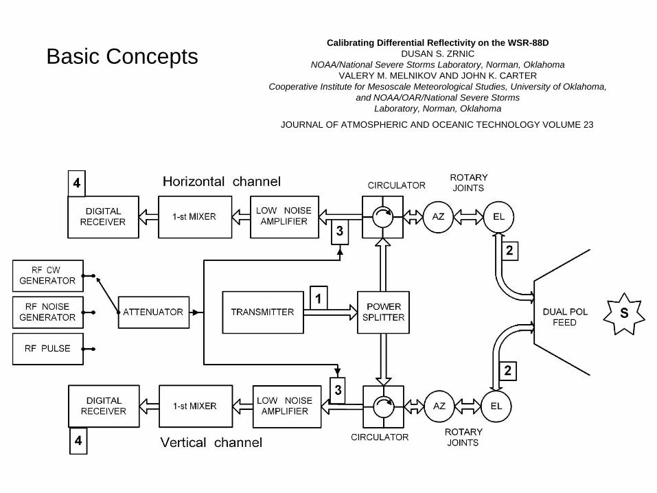
Calibrating Differential Reflectivity on the WSR-88D
DUSAN S. ZRNIC
NOAA/National Severe Storms Laboratory, Norman, Oklahoma
VALERY M. MELNIKOV AND JOHN K. CARTER
Cooperative Institute for Mesoscale Meteorological Studies, University of Oklahoma,
and NOAA/OAR/National Severe Storms
Laboratory, Norman, Oklahoma
JOURNAL OF ATMOSPHERIC AND OCEANIC TECHNOLOGY VOLUME 23
Basic Concepts
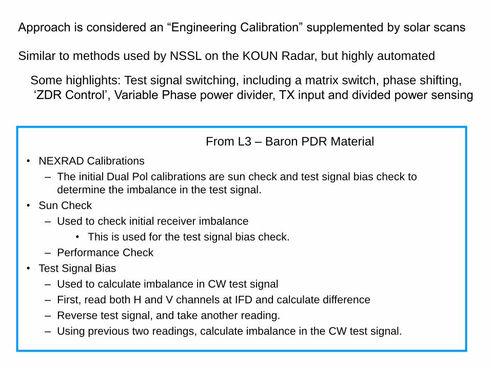
• NEXRAD Calibrations
– The initial Dual Pol calibrations are sun check and test signal bias check to
determine the imbalance in the test signal.
• Sun Check
– Used to check initial receiver imbalance
• This is used for the test signal bias check.
– Performance Check
• Test Signal Bias
– Used to calculate imbalance in CW test signal
– First, read both H and V channels at IFD and calculate difference
– Reverse test signal, and take another reading.
– Using previous two readings, calculate imbalance in the CW test signal.
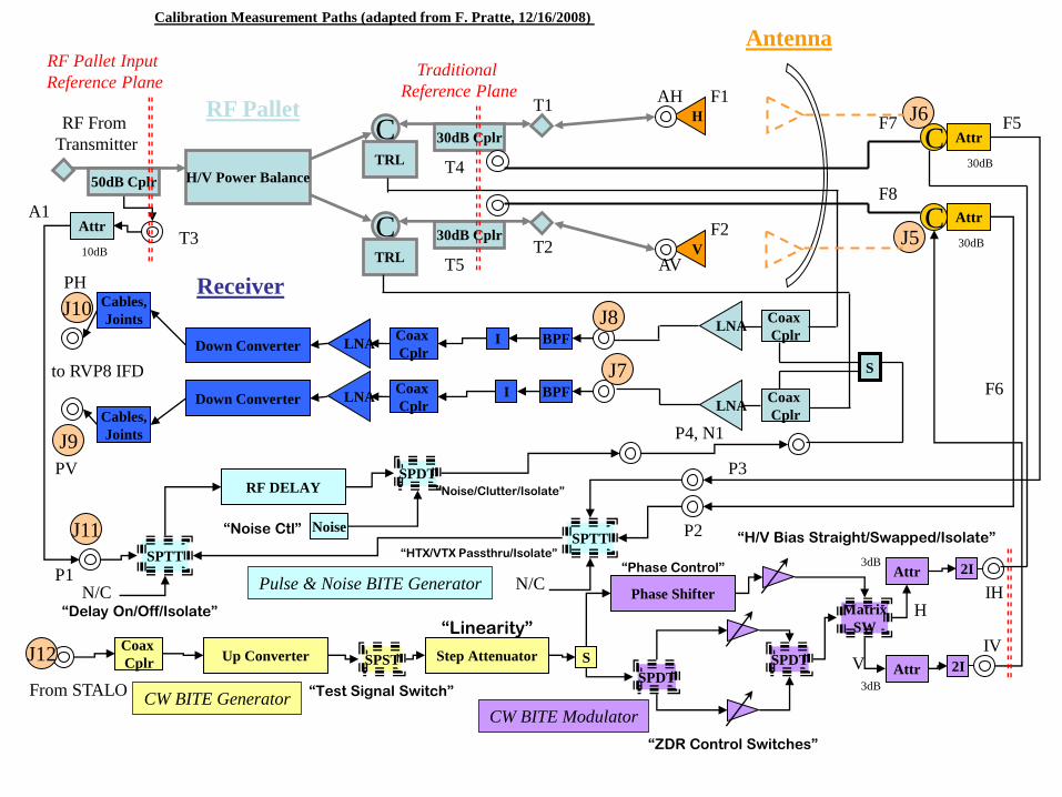
From L3 – Baron PDR Material
Approach is considered an “Engineering Calibration” supplemented by solar scans
Similar to methods used by NSSL on the KOUN Radar, but highly automated
Some highlights: Test signal switching, including a matrix switch, phase shifting,
„ZDR Control‟, Variable Phase power divider, TX input and divided power sensing

RF Pallet Antenna
Receiver
Pulse and Noise BITE Generator
CW BITE Generator
CW BITE
Modulator
TX Signal
RVP8
AME
TX Power Sense H & V
Power Sense
STALO
H & V Bias
CW Tests
KD, Noise
TX Sense
H V
H
V
•Power divider
•Isolator
•TR limiter
•Couplers
•LNA‟s
•Couplers
•filters
•LNA‟s
•Down converter
•RF Delay
•Noise Source
•Up converter
•Step attenuator
•Two channels
•Phase shifter
•Matrix switch
H
V
IF Signals
Design
Functional
Relationships
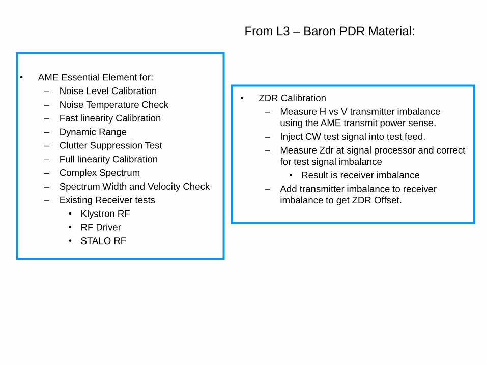
• AME Essential Element for:
– Noise Level Calibration
– Noise Temperature Check
– Fast linearity Calibration
– Dynamic Range
– Clutter Suppression Test
– Full linearity Calibration
– Complex Spectrum
– Spectrum Width and Velocity Check
– Existing Receiver tests
• Klystron RF
• RF Driver
• STALO RF
From L3 – Baron PDR Material:
• ZDR Calibration
– Measure H vs V transmitter imbalance
using the AME transmit power sense.
– Inject CW test signal into test feed.
– Measure Zdr at signal processor and correct
for test signal imbalance
• Result is receiver imbalance
– Add transmitter imbalance to receiver
imbalance to get ZDR Offset.
H/V Power Balance
C
C
TRL
TRL
LNA
LNA
Down Converter
Down Converter
50dB Cplr
30dB Cplr
V
I
I
BPF
BPF
Coax
Cplr
30dB Cplr
Coax
Cplr
Up Converter Coax
Cplr SPST
SPTT
RF DELAY
Step Attenuator
SPDT
S
Matrix
SW
S
Phase Shifter
SPDT
SPDT
2I
2I
Attr
Noise
Attr
C Attr
C Attr
SPTT
Attr
N/C N/C
RF Pallet
Receiver
Pulse & Noise BITE Generator
CW BITE Generator CW BITE Modulator
to RVP8 IFD
RF From
Transmitter
T1
T2
“Test Signal Switch”
“ZDR Control Switches”
“H/V Bias Straight/Swapped/Isolate”
F1
F2 T3
T4
T5
F5
F6
IH
IV
P2
P1
P4, N1
“Phase Control”
“Linearity” “Delay On/Off/Isolate”
“Noise/Clutter/Isolate”
H
V
From STALO
“Noise Ctl”
P3
“HTX/VTX Passthru/Isolate”
Antenna
Traditional
Reference Plane
A1
Calibration Measurement Paths (adapted from F. Pratte, 12/16/2008)
AH
AV
RF Pallet Input
Reference Plane
10dB 30dB
30dB
3dB
3dB
PH
PV
F7
F8
Cables,
Joints
Cables,
Joints
J6
J5
J8
J7
J9
J10
J11
J12
LNA
LNA
Coax
Cplr
Coax
Cplr

RF Pallet Antenna
Receiver
Pulse and Noise BITE Generator
CW BITE Generator
CW BITE
Modulator
TX Signal
RVP8
AME
TX Power Sense H & V
Power Sense
STALO
H & V Bias
CW Tests
KD, Noise
TX Sense
H V
H
V
•Power divider
•Isolator
•TR limiter
•Couplers
•LNA‟s
•Couplers
•filters
•LNA‟s
•Down converter
•RF Delay
•Noise Source
•Up converter
•Step attenuator
•Two channels
•Phase shifter
•Matrix switch
H
V
IF Signals
Example
TX Power
Sense

RF Pallet Antenna
Receiver
Pulse and Noise BITE Generator
CW BITE Generator
CW BITE
Modulator
TX Signal
RVP8
AME
TX Power Sense H & V
Power Sense
STALO
H & V Bias
CW Tests
KD, Noise
TX Sense
H V
H
V
•Power divider
•Isolator
•TR limiter
•Couplers
•LNA‟s
•Couplers
•filters
•LNA‟s
•Down converter
•RF Delay
•Noise Source
•Up converter
•Step attenuator
•Two channels
•Phase shifter
•Matrix switch
H
V
IF Signals
Example
H Power
Sense
RF Pallet Antenna
Receiver
Pulse and Noise BITE Generator
CW BITE Generator
CW BITE
Modulator
TX Signal
RVP8
AME
TX Power Sense H & V
Power Sense
STALO
H & V Bias
CW Tests
KD, Noise
TX Sense
H V
H
V
•Power divider
•Isolator
•TR limiter
•Couplers
•LNA‟s
•Couplers
•filters
•LNA‟s
•Down converter
•RF Delay
•Noise Source
•Up converter
•Step attenuator
•Two channels
•Phase shifter
•Matrix switch
H
V
IF Signals
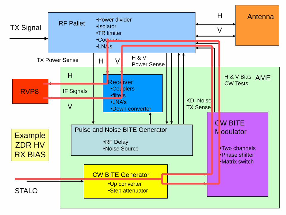
Example
ZDR HV
RX BIAS
RF Pallet Antenna
Receiver
Pulse and Noise BITE Generator
CW BITE Generator
CW BITE
Modulator
TX Signal
RVP8
AME
TX Power Sense H & V
Power Sense
STALO
H & V Bias
CW Tests
KD, Noise
TX Sense
H V
H
V
•Power divider
•Isolator
•TR limiter
•Couplers
•LNA‟s
•Couplers
•filters
•LNA‟s
•Down converter
•RF Delay
•Noise Source
•Up converter
•Step attenuator
•Two channels
•Phase shifter
•Matrix switch
H
V
IF Signals
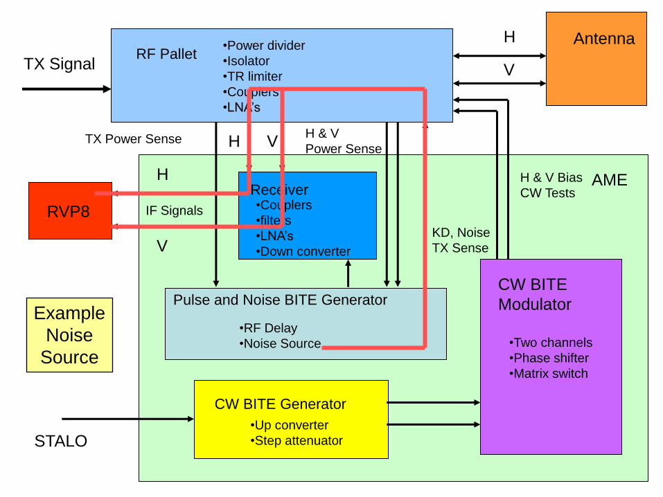
Example
Noise
Source
Summary of L3 - Baron Approach
• Some elements “Factory Calibrated”, meaning paths measured with
calibrated power meters
• Some paths calibrated using a noise source (tracable to NIST)
• Z calibration essentially same as WSR-88D, determine dBZo and
ensure the receiver is linear
• ZDR calibration accomplished via combination of solar scans, power
sense path difference measurements, test path calibrations, and
through use of a matrix switch to cross connect CW test signals
• All basic WSR-88D calibration and fault monitoring functions are
integrated into the design
• System Initial Phase Determination based on ground clutter targets