lab 4 experiments 8 and 9. same circuit: experiment 8 and 9
TRANSCRIPT

Lab 4
Experiments 8 and 9

Same Circuit: Experiment 8 and 9

Labeling Nodes
Left click on the wire attached to the node that you want to label.
Go to Edit/Label and enter the name of the node in the Set Attribute Value pop-up window and click OK.
Alternatively, just double click on the wire and the Set Attribute Value window will open.

Setting Resistor Tolerance - Schematics
• Double click on the resistor• In the pop-up window entitled Part Name,
click on the part attribute called Tolerance.– In the window below VALUE, enter 5% and then
click Save Attr and then click OK.• 5% will appear next to the resistor symbol.


Setting Resistor Tolerance - Capture
• Double click on a resistor, which launched a pop-up window entitled Property Editor.– Change the entry after Filtered by: to <Current
Properties> if not already set to this.– Scroll across the properties until you find
TOLERANCE. • Type 5% into the window below TOLERANCE and then
clode the pop-up window.


For all Pspice Programs
• If you make the change to the TOLERANCE on the first resistor that you place in the circuit and then copy the resistor to place the other resistors into the circuit, you only need to modify the TOLERANCE of the resistors once.
• If you place all of the resistors into the circuit before changing the properties, you will need to click on each resistor and enter ‘5%’ into TOLERANCE.
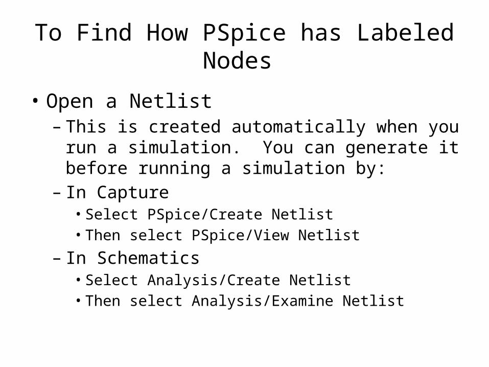
To Find How PSpice has Labeled Nodes
• Open a Netlist– This is created automatically when you run a
simulation. You can generate it before running a simulation by:
– In Capture• Select PSpice/Create Netlist• Then select PSpice/View Netlist
– In Schematics• Select Analysis/Create Netlist• Then select Analysis/Examine Netlist
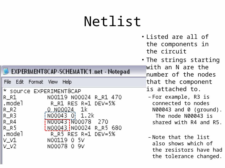
Netlist• Listed are all of the
components in the circuit• The strings starting with
an N are the number of the nodes that the component is attached to. – For example, R3 is
connected to nodes N00043 and 0 (ground). The node N00043 is shared with R4 and R5.
– Note that the list also shows which of the resistors have had the tolerance changed.

Labeling Nodes - Schematics
1. Left click on wire next to the node that you would like to label so that it is highlighted in red.
2. Click on Edit/Label3. Type the label into
the Set Attribute Value pop-up window and click OK.

Setting up a Monte Carlo Simulation
• Monte Carlo simulations in Pspice can be run as either:– a worst case analysis where the maximum
deviation from the nominal values of each component are used in the calculations
– a statically-driven variation from the nominal values of the components using a bell shaped curve for the distribution of deviations.

Monte Carlo
• Set up a Simulation Run– You must select one of the other types of analysis first
• Click on DC Sweep– Pick either of the voltage sources to sweep
» Make both the start and end values equal to the value of the voltage source, pick any value for the increment, and click OK.
– Then, select Monte Carlo/Worst Case• Enter V(node name) or V(component:node)
– Note that you will also have to put a voltage marker on to the circuit schematic no matter what you put as the output variable
• Enter the number of runs (500 is recommended)• In Capture, pick a random number between 1 and 32767 and select
uniform for the distribution.
– Do not unselect the Bias Point Detail

Output Plot

Finding the Thevenin Equivalent Resistance
• There are several methods that can be used to determine the Thevenin equivalent resistance, RTH, of a circuit.
1. Find the open circuit voltage and short circuit current: RTH = VOC/ISC
Also used in calculating the Load Line of a circuit, which will be used frequently in ECE 2204 and 3204.
2. Source transformationNorton/Thevenin Conversions - emphasized in the lecture portion of the course.

Determine VOC
Replace R5 with an open circuit and determine the voltage across the nodes where R5 had been attached (Nodes X and Y).

The polarity of VOC is not important when calculating RTH. However, the way you orient the +/_ signs for VOC will determine the direction of the short circuit current, which will be calculated next.
The value of VOC is the final Thevenin equivalent voltage source for the circuit.
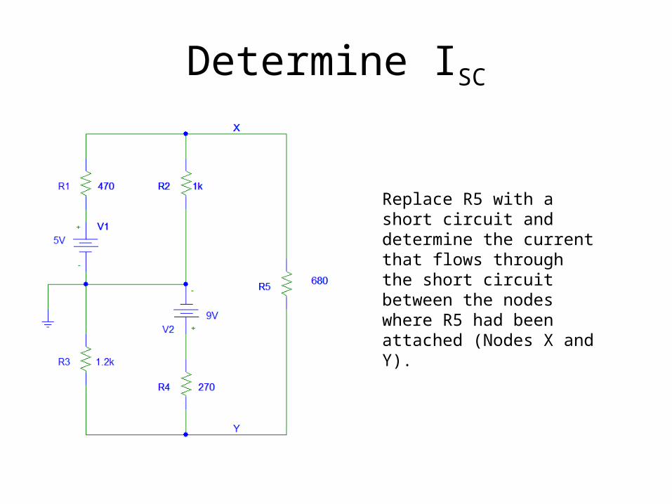
Determine ISC
Replace R5 with a short circuit and determine the current that flows through the short circuit between the nodes where R5 had been attached (Nodes X and Y).

The short circuit current should flow out of the – side of the open circuit voltage.
RTH = VOC /ISC
The value of ISC is the final Norton equivalent current source for circuit.