lab apparatuses: airfoil performance lab, otto cycle, and
TRANSCRIPT

3
Lab Apparatuses: Airfoil Performance Lab, Otto Cycle, and Dimensional Analysis
A Baccalaureate thesis submitted to the Department of Mechanical and Materials Engineering College of
Engineering and Applied Science University of Cincinnati
in partial fulfillment of the
requirements for the degree of
Bachelor of Science
in Mechanical Engineering Technology
by
Thomas F. Lawlor Tyler Dreyer
April 2019
Thesis Advisor:
Professor Muthar Al-Ubaidi, Ph.D.

4
ACKNOWLEDGEMENTS We would like to thank all the individuals that were instrumental in the successful
completion of this senior design project. First and foremost, we would like to extend our
gratitude to Professor Muthar Al-Ubaidi, Ph.D. who, as our advisor offered invaluable input into
these projects and extended the opportunity to us in the first place to focus on lab apparatuses as a senior design project. With prior experience in the aerospace industry, it was a real treat to
design, manufacture and test a subsonic, open-return wind tunnel. This project could not have been successfully completed without the immense help and resources from the Lawlor, Stump, and Dreyer families of Cincinnati, Ohio. Most of the tools required for manufacture and assembly came from these families, and with an already small operating budget,
would have been overextended without their help if the purchasing of tools was needed alongside the materials. We would like to thank Sam Taylor, who without his machining and design skills,
we would still be searching for a means to connect the lift and drag sensors underneath the test section. Sam provided us with a solution that met our product objectives. We would like to thank our fellow classmate, Brandon Potter, who extended us the use of his 3D printer to print the airfoils for the Airfoil Performance Lab. And lastly, the Tech Expo judges that awarded us with
the Brinkerhoff 2nd Best Overall of Show and the accompanying scholarship.

5
TABLE OF CONTENTS
ACKNOWLEDGEMENTS.................................................................................................... IV
TABLE OF CONTENTS......................................................................................................... V
LIST OF FIGURES ................................................................................................................ VI
LIST OF TABLES.................................................................................................................VII
ABSTRACT......................................................................................................................... VIII
PROBLEM DEFINITION AND RESEARCH ........................................................................ 1
PROBLEM STATEMENT .................................................................................................................. ......................1
BACKGROUND............................................................................................................................. ........................1
RESEARCH.............................................................................................................................. 2
SCOPE OF THE PROBLEM............................................................................................................................. .........2
CURRENT STATE OF THE ART ............................................................................................................................. .3 END USER........................................................................................................................ ....................................4
CONCLUSIONS AND SUMMARY OF RESEARCH.....................................................................................................4
CUSTOMER FEATURES ....................................................................................................... 5
PRODUCT OBJECTIVES ....................................................................................................... 5
QUALITY FUNCTION DEPLOYMENT ............................................................................... 6
DESIGN.................................................................................................................................... 8
DESIGN ALTERNATIVES......................................................................................................................................8
Design Concept 1.................................................................................................................... ......................8
Design Concept 2............................................................................................................................ ............10 Design Concept 3........................................................................................................................................11
SELECTED DESIGN CONCEPT 3 DRAWINGS.......................................................................................................13
COMPONENT SELECTION – AIRFOIL PERFORMANCE LAB APPARATUS .............................................................15
Wind Tunnel Fan.......................................................................................................................... ...............15
Wind Tunnel Force Gauges ........................................................................................................................16
Wind Tunnel Quick Releases.............................................................................................. .........................16 Airfoil Solid-Model Coordinate Curve Fit..................................................................................................17
Airfoil Solid-Model .....................................................................................................................................19
COMPONENT SELECTION – DIMENSIONAL ANALYSIS LAB APPARATUS ...........................................................20
Digital Flow Meter: ....................................................................................................................................20
Dual Differential Digital Manometer: ........................................................................................................20
BILL OF MATERIALS .................................................................................................................................... .....21 Airfoil Performance Lab Apparatus............................................................................................................21
Dimensional Analysis Lab Apparatus...................................................................................................... ...21
Otto Cycle Lab Apparatus.................................................................................................................... .......22
PROJECT MANAGEMENT.................................................................................................. 23
BUDGET, PROPOSED/ACTUAL............................................................................................................................23
Airfoil Performance Lab Apparatus: ..........................................................................................................23 Otto Cycle Lab Apparatus: .........................................................................................................................23
Dimensional Analysis Lab Apparatus:........................................................................................................24
SCHEDULE, PROPOSED (LEFT) /ACTUAL (RIGHT) ..............................................................................................24
Airfoil Performance Lab Apparatus: ..........................................................................................................24
Otto Cycle Lab Apparatus: ............................................................................................. ............................25

6
Dimensional Analysis Lab Apparatus:........................................................................................................25
CONCLUSIONS ..................................................................................................................................................26
PROJECT SUMMARY.......................................................................................................... 27
WORKS CITED ..................................................................................................................... 28
APPENDIX A......................................................................................................................... 29
SURVEY RESULTS FROM PREVIOUS STUDENTS – SURVEY MONKEY .................................................................29
APPENDIX B ......................................................................................................................... 32
AIRFOIL PERFORMANCE LAB CONSTRUCTION PHOTOS AND EQUATIONS .........................................................32
APPENDIX C ......................................................................................................................... 39
AIRFOIL PERFORMANCE LAB AIRFOIL DESIGN DOCUMENTS ............................................................................39
LIST OF FIGURES Figure 1: House of Quality Engineering & Customer Requirements
Figure 2: House of Quality Interaction Matrix Figure 3: Concept 1a: Mid-mounted access door and aft mounted gauge. Figure 4: Concept 1b: Forward-mounted access door and gauge. Figure 5: Concept 1c: Aft-mounted access door and gauge.
Figure 6: Flow analysis of existing Fan Performance Lab Apparatus
Figure 7: Design concept 2 for the Airfoil Performance Lab Apparatus
Figure 8: Design concept 3 for the Airfoil Performance Lab
Figure 9: Flow analysis of design concept 3, point matrix
Figure 10: Flow analysis of design concept 3, linear matrix
Figure 11: Overall tunnel construction document and characteristics
Figure 12: Contractor cone, test section, diffusion nozzle, and airfoil characteristics and
dimension construction document. Figure 13: Airfoil Performance Lab Apparatus governing construction equations, excel capable. Figure 14: Airfoil Performance Lab Apparatus full assembly drawing. Figure 15: Selected gable-mounted fan. Figure 16: Selected Vernier force gauges for lift and drag measurements. Figure 17: Selected wind tunnel quick release clasps. Figure 18: Student designed sub-sonic, laminar flow, semi-symmetrical airfoil for apparatus testing (x3). Figure 19: Selected flow meter for Dimensional Analysis Lab Apparatus
Figure 20: Selected digital manometer for Dimensional Analysis Lab Apparatus

VII
LIST OF TABLES Table 1: Fan specifications
Table 2: Curve-fit coordinates for laminar flow, sub-sonic, semi-symmetrical airfoil. Table 3: BOM for Airfoil Performance Lab
Table 4: BOM for Dimensional Analysis Lab
Table 5: BOM for Otto Cycle Lab.
Tables 6 & 7: Project vs. actual budgets of the Airfoil Performance Lab.
Tables 8 & 9: Project vs. actual budgets of the Otto Cycle Lab. Tables 10 & 11: Project vs. actual budgets of the Dimensional Analysis Lab. Table 12: Predicted vs. actual schedule for Airfoil Performance Lab. Table 13: Predicted vs. actual schedule for Otto Cycle Lab.
Table 14: Predicted vs. actual schedule for Dimensional Analysis Lab.

VIII
ABSTRACT The objective of this senior design project was to reintroduce the Otto Cycle Lab Apparatus
that had fallen out due to unsteady-state operation, and to introduce a new Dimensional
Analysis Lab Apparatus that was never previously introduced, as it was not producing
repeatable or precision results, rendering it useless for educational purposes. Team
deliverables for these two apparatuses were to achieve steady-state operation and repeatable
results. The last objective was to design and introduce a new lab apparatus which was
capable of measuring drag forces in order to calculate drag coefficients on 3-dimensional
objects. The team ultimately took this deliverable one step further, providing a means to
measure lift force and thusly, calculate lift coefficients on any 3-dimensional object that that
does not exceed 10% of the cross-sectional area of the test section on the designed wind
tunnel. This apparatus became the Airfoil Performance Lab. The purpose of this senior
design project is to provide the MET department with more lab apparatuses to promote full
participation by students during these classes, as there is currently a shortage of them.

Senior Design Report 2019 Thomas F. Lawlor & Tyler Dreyer
1
PROBLEM DEFINITION AND RESEARCH
PROBLEM STATEMENT
A problem the MET department at the University of Cincinnati is facing is there are not
enough lab apparatuses for the number of students in the lab classes. While lab is in session,
only a couple students are actively involved in the apparatuses, while most of the students in
the classes stand and watch the professor and other students perform the lab experiment. This
is a disservice to students’ learning. The senior design team of Thomas Lawlor and Tyler
Dryer propose introducing a new lab apparatus and reintroducing two other lab experiments
that are currently not functioning correctly and that have fallen out of rotation.
The experiments that need to be troubleshooted, tested, and improved/redesigned based on
Muthar Al-ubaidi’s request are the internal combustion lab and the dimensional analysis lab.
Currently, the internal combustion lab’s engine is not running, and when it does run, the
engine RPM is not steady, which is necessary for the calculations the students must solve.
The dimensional analysis lab apparatus does not have accurate gauges for the manometer or
the flow rate, making multiple runs of the same system set-up result in different values.
Lastly, the apparatus that needs a new component is the fan performance lab. Thomas and
Tyler will either take the existing lab and design in provisions for either measuring the drag
force or calculating the drag force on 3 given objects of certain geometry to determine the
coefficient of drag on each that can be compared to theoretical values, or an entirely new
apparatus will have to be designed and manufactured to measure the forces. Further research
is required. A lab document for both the instructor and the students will be created for each
of the experiments and published. Any additional information required to run the apparatuses
that is not relevant to the published lab documents will also be included in the final product.
Funding will come from the University of Cincinnati, the manufacturers of any equipment
that may be required, and the students if making up the balance is required. The University of
Cincinnati will own all these lab apparatuses and intellectual property.
BACKGROUND
There are three lab apparatuses in the MET department for student labs that require attention
and need to be introduced or reintroduced as there is already a shortage of lab experiments
for students.
The internal combustion lab has fallen out of the rotation of lab experiments for MET
students as it is currently not functioning. There is an issue with the horizontal shaft engine;
it is the main component of the apparatus. The engine needs to either be overhauled or
replaced. When the lab was functioning properly, there was an electric start option that no
longer exists and the pull cord on the engine is not in an ergonomically friendly position on
the apparatus’ frame, necessitating the need for reintroduction of an electric start or designing
a provision for easier manual start. Also, when the engine was running, it was not running
properly. Maintaining a set RPM is imperative for the lab calculations and the fluctuations

Senior Design Report 2019 Thomas F. Lawlor & Tyler Dreyer
2
caused by a rough-running engine were making this difficult. The internal combustion lab
needs to be more reliable.
The dimensional analysis apparatus was never implemented into the rotation of lab
experiments for MET students. A student lab document and an instructor lab document need
to be created for this experiment that will compare 3 measured values vs. 3 calculated values
and their percent errors. The lab was a previous senior design project that needs to be
redesigned as it lacks appropriate increments on the measurement tools and does not read
consistently on the manometers and the flow rate gauge.
The fan performance lab either needs to be redesigned with provisions to measure or
calculate the drag coefficients on three different geometries, or an entirely new lab (wind
tunnel) needs to be designed and manufactured to meet positive flow characteristics. There is
currently no provision that allows the user to measure the drag force on the objects, which is
required for calculating the drag coefficients. The student lab document and instructor lab
documents will have to be updated to include this new set-up and test. Determining these
values are core competencies in wind tunnel testing that need to be designed into the MET
department’s lab rotation.
RESEARCH
SCOPE OF THE PROBLEM
Addressing the problems in the lab apparatuses is important as there is already a lack of lab
experiments for the increasing number of engineering students the University of Cincinnati is
seeing each year. The MET department’s goal is to have all students in a standard size class
working on multiple apparatuses in small groups, allowing everyone the opportunity to
participate in the labs and have touch time, rather than standing around in one large group
watching only a couple students interact with one lab per class. This is a disservice to the
students.
Not only is there a lack of lab apparatuses and by introducing/reintroducing the selected
apparatuses will it get the MET department closer to its goal, keeping the work on these
apparatuses in house keeps the cost down. These experiments are built with specific,
intended purposes. For example, the internal combustion lab measures the efficiency of an
internal combustion engine. If such an apparatus was made outside of UC for the MET
department, it would cost tens of thousands of dollars as it would have to be an entirely
custom-built product. It is not a standard product that is mass produced or readily available
for sale and the funding for new, state-of-the-art equipment an accredited engineering college
should have is often not enough or available.

Senior Design Report 2019 Thomas F. Lawlor & Tyler Dreyer
3
CURRENT STATE OF THE ART
For the internal combustion lab apparatus, there is currently no product on the market readily available that is purpose built for the public to calculate the efficiency of a small displacement, horizontal shaft internal combustion engine. It is a unique apparatus, making it an imperative to fix. Car manufactures, such as Ford and General Motors, use large-scale multi-million-dollar engine dynos to test the efficiency of their internal combustion engines so the idea itself is not new. The engine in use on the lab apparatus is a 2001 Briggs and Stratton unit with a horsepower range between 3.5-6.5hp and displacement of 206cc. [4] Current, comparable engines made by Briggs and Stratton and other manufactures have been updated with OHV technology and technology that removes the need for oil changes. These engines, commonly referred to as clone engines, are also overwhelming used in go kart motorsports. Electric start has become a standard integration on these small engines and even on push mowers such as the Toro Personal Pace push-mower.
The dimensional analysis apparatus’ key components are the pump, the flow meter, and the
manometer. The gauges or the system itself are contributing to the inconsistencies of
measurements. The gauges do not have the appropriate increments needed for scrutinized
analysis. The state-of-the-art alternatives for the flow meter and the manometer are digital
readout gauges from companies like OMEGA. There are also more precise, analog gauges
available that are more budget friendly than their digital counterparts.
Wind tunnels are used across many industries including the automotive, aerospace, and
entertainment industries. Automakers such as Ford Motor Company and General Motors and
aerospace companies such as Boeing use wind tunnels to test the aerodynamics of new
designs of cars, planes etc. More aerodynamic bodies usually equate to higher efficiency.
NASA currently employs the use of wind tunnels with attached strain gauge mechanisms to
measure the drag forces on certain objects. The strain gauge feeds measurements to a
computer that transforms the measurements into drag data. [1] The drag force is directly
proportional to the drag coefficient and drag force measurements are used to determine the
drag coefficients of objects. [2] Other methods for measuring the drag forces on objects in
wind tunnels include using elements floating on water, elements on water with a mechanical
device, oil baths, and other standard load cells. [3] These are direct methods for
measurements of drag force. There also exists indirect methods for measurements. For
example, a variety of optical approaches which will not be used. [3] State of the art wind
tunnels, such as ARC’s moving ground wind tunnel, typically have the power to generate 50
m/s wind speeds (roughly 115 mph). [2]

Senior Design Report 2019 Thomas F. Lawlor & Tyler Dreyer
4
END USER
The end users for each of the three lab apparatuses are MET students and the department’s
lab instructors.
For the Internal Combustion Lab, the users should find that the engine runs again. On top of
diagnosing and repairing the lab, the users will find that the engine runs more smoothly than
before the tune and has easier start-up. The lab document will be updated with sustainable
practices for maintenance of the engine and test stand to avoid future failure.
For the Dimensional Analysis Lab, the users should find that the updated gauges are easier to
read, and results will be consistent as they previously were not, which is why the lab was
never introduced. An easy to follow lab document, for both students and instructors will be
created for the lab. Any modification to the overall system will be conceived for the
convenience of the operators.
For the Fan Performance or new Airfoil Performance Lab, the users will find that they will
be able to measure three different drag forces of three different geometries and be able to
calculate their drag coefficients. This is not currently possible with the current fan
performance wind tunnel. Students and instructors will find switching between geometries
very easily.
CONCLUSIONS AND SUMMARY OF RESEARCH
From the research, the team has learned that the lab apparatuses are unique in that they are not readily purchasable on the market as non-custom units. Repairing the inoperable lab apparatuses and adding an important, fundamental feature of fluid mechanics to the wind tunnel that it currently does not have is vitally important. It will not only save tens-of- thousands of dollars for the University of Cincinnati, but it will provide more labs for the MET students to utilize and foster a better, hands-on learning experience.
The research has pointed the team in the direction of digitalization where possible as this is the state of the art. This includes the flow meter and manometers for the dimensional analysis
lab and for any gauges for the wind tunnel redesign. Digitalization will provide the students
and instructors with the most accurate measurements for their calculations in their lab
documents, bringing the labs into the 21st century. The wind tunnel should be tested for a
wind speed of 10 m/s as this is also state of the art for small scale wind tunnels. [2] There are
multiple methods of measuring drag force in a wind tunnel. From the methods researched, we
will choose later the most feasible, least cost, and user-friendly method during the design
phase of the project.

Senior Design Report 2019 Thomas F. Lawlor & Tyler Dreyer
5
CUSTOMER FEATURES
Students were poled on a scale of 1-5, 5 being very important to them and 1 being least
important. The average results are as follows. Data was collected online via survey monkey
and in person orally from previous lab students.
1. Easily navigable lab documents – 3.5
2. Length of procedure – 4
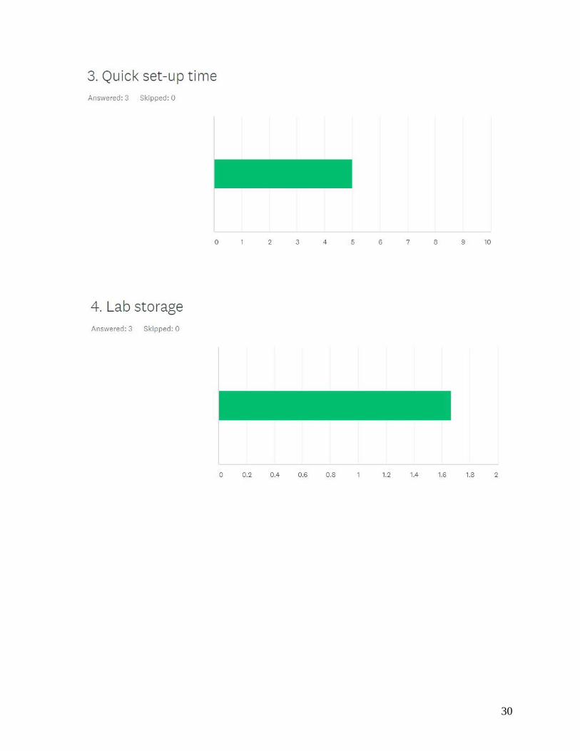
3. Quick set-up time – 3.25
4. Lab storage - 1
5. Easy to record experimental data values – 4.5
6. Easy interchange between trials – 5
PRODUCT OBJECTIVES
The following product objectives are ranked in order of team priority.
1. Easy setup procedure
a. To meet this objective, the use of tools for setup and/or assembly will be
minimal or zero.
2. Easy shutdown procedure
a. To meet this objective, the use of tools for shutdown will again be minimal or
zero.
3. Quick connections and disconnections between trials
a. This objective will be met by not using any special tools for connections or
disconnections, particularly within the proposed drag measurement apparatus.
4. Digital readouts
a. The retention of digital readouts that are accurate will be retained in the Otto
Cycle apparatus.
b. Digital readouts will be available on the Dimensional Analysis lab that will be
in the form of a manometer and a flow rate gauge for more accurate results.
c. Digital readouts will be available for the forces being measured in the new
wind tunnel apparatus.
5. Quick “winterization” for continued reliability purposes
a. Instructions for winterization of the labs will be included in the lab
documents.
6. Minimal pages in lab document
a. Clear and concise instructions for running the labs.
7. Clearly labeled apparatuses (buttons/switches)
a. Will aide in assembly and disassembly as well as running the apparatuses, in
the lab document instructions.
8. Tables and charts in lab documents
Senior Design Report 2019 Thomas F. Lawlor & Tyler Dreyer
6
a. Examples to help students comprehend the labs.
9. Portability
a. The Otto Cycle will retain its wheels, as well as the Dimensional Analysis lab.
The new wind tunnel apparatus will be designed in three sections.
10. Minimal amount of fasteners
a. Clasps that require no tools will hold the wind tunnel sections in place.
QUALITY FUNCTION DEPLOYMENT
Engineering Characteristics
1. Navigation time (sec)
2. Pages in Lab Document (#)
3. Setup time (min)
4. Storage Space (sqft)
House of Quality
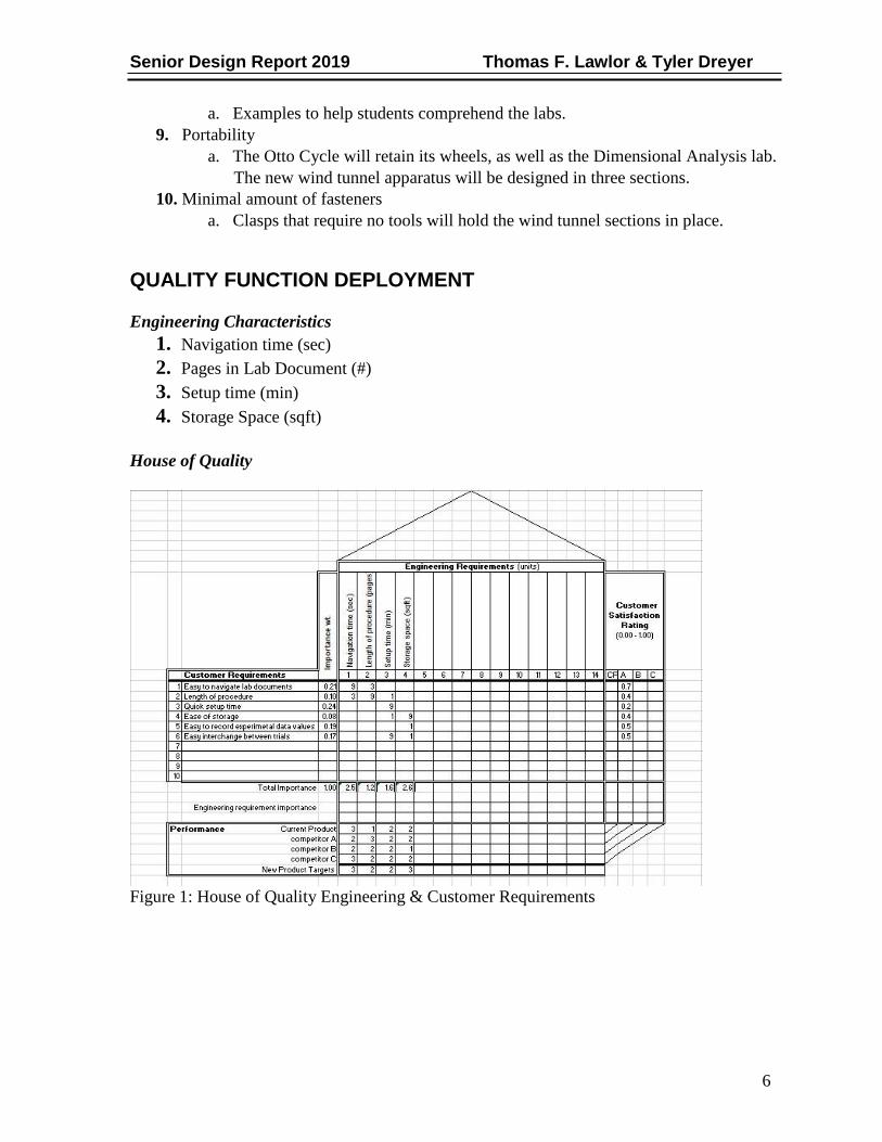
Figure 1: House of Quality Engineering & Customer Requirements

Senior Design Report 2019 Thomas F. Lawlor & Tyler Dreyer
7
Figure 2: House of Quality Interaction Matrix

Senior Design Report 2019 Thomas F. Lawlor & Tyler Dreyer
8
DESIGN
DESIGN ALTERNATIVES
Design Concept 1
This concept involved retrofitting the existing Fan Performance Lab in the MET cage and
designing in the drag force measurement into the top of the tube with a trap door provision.
The main benefit to this concept is keeping the footprint of the apparatus small, as there is
already not much space available. As this lab already exists, there is no net gain in used area
within the MET cage.
The downfall to this design is that the fan performance lab and the flow characteristics within
the tube are not optimal for aerodynamic testing. The Reynolds number was calculated to be
a very turbulent 281,632. Ultimately, this design was not chosen as the measured forces
would not be repeatable.
Figure 3: Concept 1a: Mid-mounted access door and aft mounted gauge.

Senior Design Report 2019 Thomas F. Lawlor & Tyler Dreyer
9
Figure 4: Concept 1b: Forward-mounted access door and gauge.
Figure 5: Concept 1c: Aft-mounted access door and gauge.

Senior Design Report 2019 Thomas F. Lawlor & Tyler Dreyer
10
Figure 6: Flow analysis of existing Fan Performance Lab Apparatus
Design Concept 2
This concept involved adding a detachable section onto the end of the existing Fan
Performance Lab flow tube that was analyzed in the first design concept. The prevailing
issue with this design was the overall length of the apparatus. At an estimated 25 feet long,
this concept does not meet the team’s objectives and it would result in shifting 3 exiting lab
apparatuses around in the MET cage.
The force induction of the air through the Fan Performance flow tube into the rest of the
wind tunnel, an expansion cone had to be added that mates to the contractor cone. With the
added complexity and extraneous length, a flow analysis was not conducted as this concept
was thrown out early.
Figure 7: Design concept 2 for the Airfoil Performance Lab Apparatus
Senior Design Report 2019 Thomas F. Lawlor & Tyler Dreyer
11
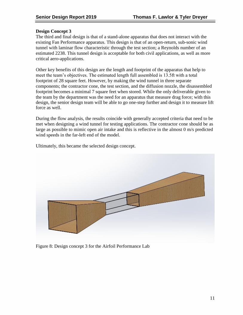
Design Concept 3
The third and final design is that of a stand-alone apparatus that does not interact with the
existing Fan Performance apparatus. This design is that of an open-return, sub-sonic wind
tunnel with laminar flow characteristic through the test section; a Reynolds number of an
estimated 2238. This tunnel design is acceptable for both civil applications, as well as more
critical aero-applications.
Other key benefits of this design are the length and footprint of the apparatus that help to
meet the team’s objectives. The estimated length full assembled is 13.5ft with a total
footprint of 28 square feet. However, by making the wind tunnel in three separate
components; the contractor cone, the test section, and the diffusion nozzle, the disassembled
footprint becomes a minimal 7 square feet when stored. While the only deliverable given to
the team by the department was the need for an apparatus that measure drag force; with this design, the senior design team will be able to go one-step further and design it to measure lift force as well.
During the flow analysis, the results coincide with generally accepted criteria that need to be
met when designing a wind tunnel for testing applications. The contractor cone should be as
large as possible to mimic open air intake and this is reflective in the almost 0 m/s predicted
wind speeds in the far-left end of the model.
Ultimately, this became the selected design concept.
Figure 8: Design concept 3 for the Airfoil Performance Lab

Senior Design Report 2019 Thomas F. Lawlor & Tyler Dreyer
12
Figure 9: Flow analysis of design concept 3, point matrix
Figure 10: Flow analysis of design concept 3, linear matrix

Senior Design Report 2019 Thomas F. Lawlor & Tyler Dreyer
13
SELECTED DESIGN CONCEPT 3 DRAWINGS
Figure 11: Overall tunnel construction document and characteristics
Figure 12: Contractor cone, test section, diffusion nozzle, and airfoil characteristics and
dimension construction document.

Senior Design Report 2019 Thomas F. Lawlor & Tyler Dreyer
14
Figure 13: Airfoil Performance Lab Apparatus governing construction equations, excel
capable.
Figure 14: Airfoil Performance Lab Apparatus full assembly drawing.

Senior Design Report 2019 Thomas F. Lawlor & Tyler Dreyer
15
COMPONENT SELECTION – AIRFOIL PERFORMANCE LAB APPARATUS
Wind Tunnel Fan
The Air-Vent 18-in gable mounted power fan was chosen based on its diameter and its CFM
rating of 1620. At this flow rate, the calculated wind speed through the test section is 11 m/s.
Figure 15: Selected gable-mounted fan.
Table 1: Fan specifications
Senior Design Report 2019 Thomas F. Lawlor & Tyler Dreyer
16
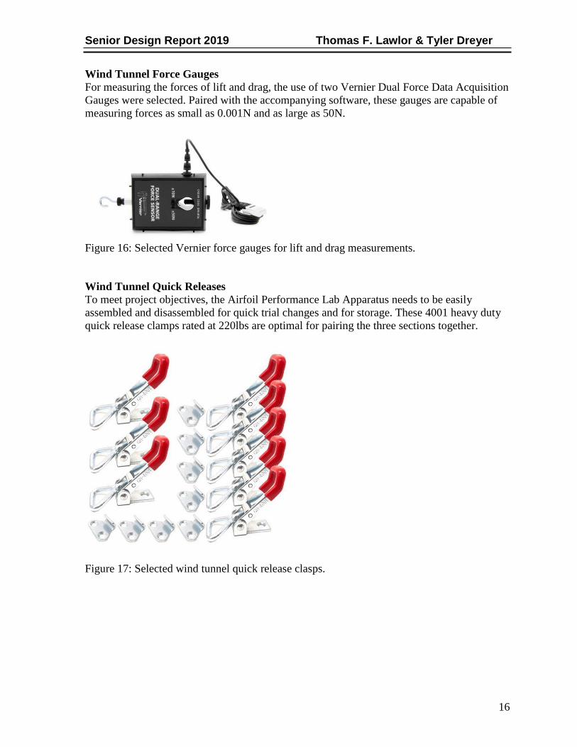
Wind Tunnel Force Gauges
For measuring the forces of lift and drag, the use of two Vernier Dual Force Data Acquisition
Gauges were selected. Paired with the accompanying software, these gauges are capable of
measuring forces as small as 0.001N and as large as 50N.
Figure 16: Selected Vernier force gauges for lift and drag measurements.
Wind Tunnel Quick Releases
To meet project objectives, the Airfoil Performance Lab Apparatus needs to be easily
assembled and disassembled for quick trial changes and for storage. These 4001 heavy duty
quick release clamps rated at 220lbs are optimal for pairing the three sections together.
Figure 17: Selected wind tunnel quick release clasps.

Senior Design Report 2019 Thomas F. Lawlor & Tyler Dreyer
17
Airfoil Solid-Model Coordinate Curve Fit
The airfoils to be measured in the wind tunnel were designed in SolidWorks with the
following curve-fit coordinates.
Airfoil Coordinates
x y z Units
50.8 0 0 mm
50.72 0.02 0 mm
50.49 0.07 0 mm
50.1 0.15 0 mm
49.57 0.26 0 mm
48.88 0.4 0 mm
48.06 0.56 0 mm
47.09 0.75 0 mm
45.99 0.96 0 mm
44.76 1.18 0 mm
43.41 1.42 0 mm
41.95 1.67 0 mm
40.39 1.92 0 mm
38.73 2.17 0 mm
36.99 2.42 0 mm
35.18 2.66 0 mm
33.31 2.9 0 mm
31.38 3.12 0 mm
29.42 3.33 0 mm
27.43 3.51 0 mm
25.43 3.67 0 mm
23.43 3.81 0 mm
21.43 3.92 0 mm
19.46 3.99 0 mm
17.51 4.02 0 mm
15.61 4.01 0 mm
13.77 3.95 0 mm
12.01 3.85 0 mm
10.33 3.71 0 mm
8.75 3.52 0 mm
7.27 3.3 0 mm
5.91 3.04 0 mm
4.67 2.76 0 mm
3.57 2.45 0 mm
2.61 2.12 0 mm
1.79 1.78 0 mm

Senior Design Report 2019 Thomas F. Lawlor & Tyler Dreyer
18
1.12 1.43 0 mm
0.6 1.07 0 mm
0.25 0.71 0 mm
0.04 0.36 0 mm
0 0 0 mm
0.11 -0.34 0 mm
0.38 -0.65 0 mm
0.8 -0.93 0 mm
1.37 -1.19 0 mm
2.08 -1.41 0 mm
2.93 -1.61 0 mm
3.92 -1.77 0 mm
5.03 -1.91 0 mm
6.26 -2.01 0 mm
7.61 -2.08 0 mm
9.06 -2.13 0 mm
10.61 -2.15 0 mm
12.25 -2.15 0 mm
13.97 -2.12 0 mm
15.75 -2.08 0 mm
17.59 -2.03 0 mm
19.48 -1.96 0 mm
21.42 -1.89 0 mm
23.39 -1.8 0 mm
25.37 -1.7 0 mm
27.35 -1.59 0 mm
29.33 -1.47 0 mm
31.28 -1.35 0 mm
33.19 -1.23 0 mm
35.06 -1.11 0 mm
36.87 -0.99 0 mm
38.61 -0.88 0 mm
40.27 -0.76 0 mm
41.84 -0.65 0 mm
43.31 -0.55 0 mm
44.67 -0.45 0 mm
45.91 -0.37 0 mm
47.03 -0.28 0 mm
48.01 -0.21 0 mm
48.85 -0.15 0 mm
49.55 -0.1 0 mm
50.09 -0.05 0 mm
50.48 -0.02 0 mm

Senior Design Report 2019 Thomas F. Lawlor & Tyler Dreyer
19
50.72 -0.01 0 mm
50.8 0 0 mm
Table 2: Curve-fit coordinates for laminar flow, sub-sonic, semi-symmetrical airfoil.
Airfoil Solid-Model
The airfoils dimensions were chosen to be 3” W x 2” L. It is imperative that the maximum
frontal area of the airfoil or any test specimen does not exceed 10% of the cross-sectional
area of the test section of the wind tunnel. Test section dimensions are 12” L x 9” H.
Figure 18: Student designed sub-sonic, laminar flow, semi-symmetrical airfoil for apparatus
testing (x3).

Senior Design Report 2019 Thomas F. Lawlor & Tyler Dreyer
20
COMPONENT SELECTION – DIMENSIONAL ANALYSIS LAB APPARATUS
Digital Flow Meter:
The Sotera flow metering unit was chosen due to its capability to measure up to 35 GPM,
which far exceeds the apparatuses pump flow rate capabilities.
Figure 19: Selected flow meter for Dimensional Analysis Lab Apparatus
Dual Differential Digital Manometer:
The Pyle digital manometer unit was chosen due to its precison measurement capabilities of
head height with a resolution of +/- 0.00 inHG and a maximum measurement capability of
+/- 55.00 inHG.
Figure 20: Selected digital manometer for Dimensional Analysis Lab Apparatus

Senior Design Report 2019 Thomas F. Lawlor & Tyler Dreyer
21
BILL OF MATERIALS
Airfoil Performance Lab Apparatus
Product Count Total
3/4in plywood 4x8 sheet 1
$ Acrylic Cuttting Tool 1
$ Plexiglass 3x4 sheet 1
$
45.98
5.21
42.98
3/4in plywood 4x8 sheet 2
$ 111.96
Eye Bolt Nuts 3/8in x 5.5 1 $
Gorilla Wood Glue 1 $
Wood screws #8 x 1-5/8in 2 $
Silicone Max White 10.1 oz 1 $
Spackling 1QT 1 $
8 AWG copper mech lugs 1 $
1/4in zinc washers 1 $
1 in hole plug 1 $
1/4in wing nuts 1 $
1620 CFM gable mount fan 1 $
3/4in plywood 2x4 1 $
Silicone weatherstrip 1 $
15A single pole toggle switch 1 $
#8 x 5/8 screws 1 $
Handy Box toggle switch cover 1 $
Handy Box 1-1/2 in 1 $
Flex Box Clamp Connectors 3/8 1 $
#8 - 1-1/4 wood screws 1 $
Hoppes Cleaner Kit (rods) 1 $
Heavy Duty Capacity Latches 2 $
Dual Force Vernier Force Gauges 2 $
3.48
3.97
12.48
8.98
7.78
1.86
1.18
2.82
1.18
99.76
25.63
9.98
0.76
2.17
0.72
1.78
2.99
6.24
21.99
27.98
49.98
Misc. Assembly HW N/a
Total
Table 3: BOM for Airfoil Performance Lab
Dimensional Analysis Lab Apparatus
$ 187.34
$ 687.18
Product Count Total

Senior Design Report 2019 Thomas F. Lawlor & Tyler Dreyer
22
Digital Manometer 1
$ Flow Meter 1
$
Misc. Fittings N/a $
55.16
84.99
12.55
Total $ 177.70
Table 4: BOM for Dimensional Analysis Lab

Senior Design Report 2019 Thomas F. Lawlor & Tyler Dreyer
23
Otto Cycle Lab Apparatus
Product Count Total
3/16in rivets 1 $
Pull Chord Handle 1 $
Hex nuts 3/4 in 1 $
Digital Tach 1 $
Misc. HW N/a $
Electrical N/a $
Angle Iron 3 FEET $
Total $
5.47
4.99
0.55
15.99
3.98
31.17
8.71
70.86
Table 5: BOM for Otto Cycle Lab.

Senior Design Report 2019 Thomas F. Lawlor & Tyler Dreyer
24
PROJECT MANAGEMENT
BUDGET, PROPOSED/ACTUAL
Airfoil Performance Lab Apparatus:
The actual budget for the Airfoil Performance Lab exceeded the projected budget due to
unforeseen miscellaneous assembly hardware.
Tables 6 & 7: Project vs. actual budgets of the Airfoil Performance Lab.
Otto Cycle Lab Apparatus:
The actual budget for the Otto Cycle Lab came in well under the projected budget due to the
sponsorship of the project by the senior design team as we donated our own personal
materials, and because the engine was able to be rebuilt and salvaged for continued use.
Tables 8 & 9: Project vs. actual budgets of the Otto Cycle Lab.

Senior Design Report 2019 Thomas F. Lawlor & Tyler Dreyer
25
Dimensional Analysis Lab Apparatus:
The actual budget for the Dimensional Analysis Lab came in well under the projected budget
as the main components, the manometer and flow meter were sourced well under expected
and initially researched prices.
Tables 10 & 11: Project vs. actual budgets of the Dimensional Analysis Lab.
SCHEDULE, PROPOSED (LEFT) /ACTUAL (RIGHT)
Airfoil Performance Lab Apparatus:
The schedule for the Airfoil Performance Apparatus was pushed only 12 days. This was a
result of minor rework for the test section assembly due to error in dimensions.
Table 12: Predicted vs. actual schedule for Airfoil Performance Lab.

Senior Design Report 2019 Thomas F. Lawlor & Tyler Dreyer
26
Otto Cycle Lab Apparatus:
The Otto Cycle Apparatus’ schedule was pushed 15 days out for completion due to
fluctuations of the RPM at set throttle and the inability to achieve steady-state operation of
the apparatus and engine. This was eventually achieved.
Table 13: Predicted vs. actual schedule for Otto Cycle Lab.
Dimensional Analysis Lab Apparatus:
The schedule for the Dimensional Analysis Lab was pushed out 26 days to completion. This
was mainly a result of the fact that the senior design team was working on two other
apparatuses at the same time as each other.
Table 14: Predicted vs. actual schedule for Dimensional Analysis Lab.
Senior Design Report 2019 Thomas F. Lawlor & Tyler Dreyer
27
CONCLUSIONS
Despite going over budget on the Airfoil Performance Lab and pushing all our target completion dates out for the Dimensional Analysis, Otto Cycle, and Airfoil Labs, the overall project was a success. Although, the budget was increased on one apparatus, mainly since the team could not source a gable-mounted fan for free from business sponsorship and to meet desired build quality, unforeseen miscellaneous manufacturing and assembly hardware had to be purchased, the other two apparatuses came in well under budget. This resulted in the final budget across all three to come in $535.00 under the original projected cost estimation.
The Airfoil Performance Lab was pushed out a week due to required rework on the test
section component. The first iteration of the test section had bonding issues with the
plexiglass to the wood framing, and the width and height dimensions at inlet and exit were
too extreme to mate successfully with the contractor cone exit and the diffusion nozzle inlet.
This apparatus also had a late start on assembly as the team had restrictions with assembly
locations and tooling. Most of the tools that were required to build this tunnel were loaned to
us from the Lawlor and Stump families of Cincinnati, Ohio. Not having the facilities to work
on such a large project indoors, the team also had to wait for spring and the weather to warm
to work on this project outside successfully. The adherence to the original design and
craftsmanship throughout manufacture resulted in a final apparatuses of exceptional build
quality and repeatability seen in the results, all while satisfying our product objectives
.
The Dimensional Analysis apparatuses was pushed out due to the nature of the problem.
When the team was first introduced to this apparatus, we knew right away that the U-bend-
style manometer was too small for the maximum flow rate of the system. Upon reverse
engineering the system, it was apparent that the head height capability of the system greatly
exceeded the apparatuses means. The original manometer had a capability of +/- 18 inHG.
With the new, digital manometer having a capability of +/- 55 inHG, the system still exceeds
this head height with the valve fully open. While the lab is now repeatable and performable
as it sits, provided the flow rate is regulated to not exceed the digital manometers capability,
the team recommends either a more capable manometer, a less powerful pump, or an AC
motor speed controller.
The Otto Cycle Apparatus used to be in the lab rotation until it fell out, due to engine issues
resulting in unsteady function, which hindered the measurement of repeatable and accurate
results. The team disassembled and overhauled the existing engine, saving approximately
$400.00 to replace it with a new engine. The apparatus runs steadily and is ready to be re-
introduced back into the rotation of the labs.
All three apparatuses are successes as they are ready to be used for the education of future
MET students.

Senior Design Report 2019 Thomas F. Lawlor & Tyler Dreyer
28
PROJECT SUMMARY This senior design was born from necessity; the need for more lab apparatuses in the MET
curriculum has been a long-time coming and a need that should surely continue. As primary
sources, having gone through the lab classes as students, the majority of lab classes proceed
as follows; the lab instructor sets up the apparatuses and assigns 1-3 students on average to
run the experiment or as required by the apparatuses, and one person to record the data. This
results in an average class section of roughly 20-25 students sitting idly by, waiting for the
measured values to be relayed, not actively being involved in the class or on the apparatuses
themselves. This is a huge detriment to many students whom could benefit from hands-on
experience and mirror that experience on co-op in the workplace. Adding more lab
apparatuses will allow the curriculum to combat this current-state where lab classes have
become more about teaching the students how to write a lab report, rather than teaching them
how to set up experiments and conduct them; where lab sections can be divided, and more
than one apparatus can be run each week. This would maximize touch-time for all students.
By introducing and reintroducing a groundbreaking, grand-total of three apparatuses from a
senior design proposal and project, we the team hope that this gets the MET department
closer to their ideal future-state goal. We hope that these apparatuses, such as the previously
unavailable to the department, Airfoil Performance Lab where students can measure lift and
drag force on different 3D printed geometries, not limited to the provided airfoils, are
maintained and utilized for the years to come.

Senior Design Report 2019 Thomas F. Lawlor & Tyler Dreyer
29
WORKS CITED
[1] Hall, N. (2018). Drag Measurement. [online] Grc.nasa.gov. Available at:
https://www.grc.nasa.gov/www/k-12/airplane/dragdat.html [Accessed 9 Oct. 2018].
[2] ARC. The ARC Moving Ground Wind Tunnel. Auto Research Center [online].
[Accessed 9 October 2018]. Available from: http://www.arcindy.com/wind-tunnel.html
[3] FAN, Zhaolin. Measurement of Aerodynamic Forces and Moments in Wind
Tunnels. Encyclopedia of Aerospace Engineering. 2010.
DOI 10.1002/9780470686652.eae078.
[4] UCCEAS. Thermodynamics Laboratory: Performance of a 4 Stroke Engine Laboratory
Manual. rep. [Accessed 27 Sept. 2018].

29
APPENDIX A
SURVEY RESULTS FROM PREVIOUS STUDENTS – SURVEY MONKEY
Previous students of the labs were poled on the following attributes.
30

31

APPENDIX B
AIRFOIL PERFORMANCE LAB CONSTRUCTION PHOTOS AND EQUATIONS
32

33

34

35

36

37

38

39
APPENDIX C
AIRFOIL PERFORMANCE LAB AIRFOIL DESIGN DOCUMENTS
Airfoil Coordinates
x y z Units
50.8 0 0 mm
50.72 0.02 0 mm
50.49 0.07 0 mm
50.1 0.15 0 mm
49.57 0.26 0 mm
48.88 0.4 0 mm
48.06 0.56 0 mm
47.09 0.75 0 mm
45.99 0.96 0 mm
44.76 1.18 0 mm
43.41 1.42 0 mm
41.95 1.67 0 mm
40.39 1.92 0 mm
38.73 2.17 0 mm
36.99 2.42 0 mm
35.18 2.66 0 mm
33.31 2.9 0 mm

40
31.38 3.12 0 mm
29.42 3.33 0 mm
27.43 3.51 0 mm
25.43 3.67 0 mm
23.43 3.81 0 mm
21.43 3.92 0 mm
19.46 3.99 0 mm
17.51 4.02 0 mm
15.61 4.01 0 mm
13.77 3.95 0 mm
12.01 3.85 0 mm
10.33 3.71 0 mm
8.75 3.52 0 mm
7.27 3.3 0 mm
5.91 3.04 0 mm
4.67 2.76 0 mm
3.57 2.45 0 mm
2.61 2.12 0 mm
1.79 1.78 0 mm
1.12 1.43 0 mm
0.6 1.07 0 mm
0.25 0.71 0 mm
0.04 0.36 0 mm
0 0 0 mm
0.11 -
0 0.34 mm
0.38 -
0 0.65 mm
0.8 -
0 0.93 mm
1.37 -
0 1.19 mm
2.08 -
0 1.41 mm
2.93 -
0 1.61 mm
3.92 -
0 1.77 mm
5.03 -
0 1.91 mm
6.26 -
0 2.01 mm

41
7.61 -
0 2.08 mm
9.06 -
0 2.13 mm
10.61 -
0 2.15 mm
12.25 -
0 2.15 mm
13.97 -
0 2.12 mm
15.75 -
0 2.08 mm
17.59 -
0 2.03 mm
19.48 -
0 1.96 mm
21.42 -
0 1.89 mm
23.39 -1.8 0 mm
25.37 -1.7 0 mm
27.35 -
0 1.59 mm
29.33 -
0 1.47 mm
31.28 -
0 1.35 mm
33.19 -
0 1.23 mm
35.06 -
0 1.11 mm
36.87 -
0 0.99 mm
38.61 -
0 0.88 mm
40.27 -
0 0.76 mm
41.84 -
0 0.65 mm
43.31 -
0 0.55 mm
44.67 -
0 0.45 mm
45.91 -
0 0.37 mm

42
47.03 -
0 0.28 mm
48.01 -
0 0.21 mm
48.85 -
0 0.15 mm
49.55 -0.1 0 mm
50.09 -
0 0.05 mm
50.48 -
0 0.02 mm
50.72 -
0
0.01 mm 50.8 0 0