lab designing and implementing a vlsm addressing scheme · pdf file... designing and...
TRANSCRIPT

© 2013 Cisco and/or its affiliates. All rights reserved. This document is Cisco Public. Page 1 of 6
Lab – Designing and Implementing a VLSM Addressing Scheme
Topology
Objectives Part 1: Examine Network Requirements
Part 2: Design the VLSM Address Scheme
Part 3: Cable and Configure the IPv4 Network
Background / Scenario Variable Length Subnet Mask (VLSM) was designed to avoid wasting IP addresses. With VLSM, a network is subnetted and then re-subnetted. This process can be repeated multiple times to create subnets of various sizes based on the number of hosts required in each subnet. Effective use of VLSM requires address planning.
In this lab, use the 172.16.128.0/17 network address to develop an address scheme for the network displayed in the topology diagram. VLSM is used to meet the IPv4 addressing requirements. After you have designed the VLSM address scheme, you will configure the interfaces on the routers with the appropriate IP address information.
Note: The routers used with CCNA hands-on labs are Cisco 1941 Integrated Services Routers (ISRs) with Cisco IOS Release 15.2(4)M3 (universalk9 image). Other routers and Cisco IOS versions can be used. Depending on the model and Cisco IOS version, the commands available and output produced might vary from what is shown in the labs. Refer to the Router Interface Summary Table at the end of this lab for the correct interface identifiers.
Note: Make sure that the routers have been erased and have no startup configurations. If you are unsure, contact your instructor.
Required Resources 3 routers (Cisco 1941 with Cisco IOS software, Release 15.2(4)M3 universal image or comparable)
1 PC (with terminal emulation program, such as Tera Term, to configure routers)
Console cable to configure the Cisco IOS devices via the console ports
Ethernet (optional) and serial cables, as shown in the topology
Lab – Designing and Implementing a VLSM Addressing Scheme
© 2013 Cisco and/or its affiliates. All rights reserved. This document is Cisco Public. Page 2 of 6
Windows Calculator (optional)
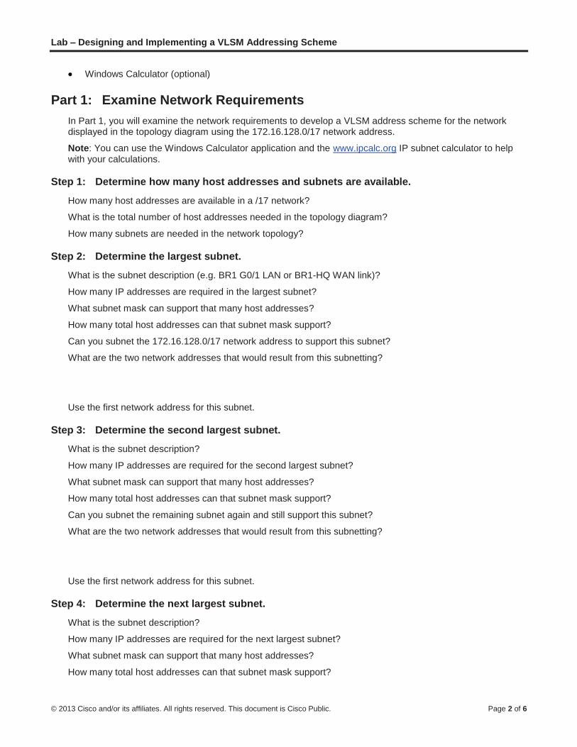
Part 1: Examine Network Requirements In Part 1, you will examine the network requirements to develop a VLSM address scheme for the network displayed in the topology diagram using the 172.16.128.0/17 network address.
Note: You can use the Windows Calculator application and the www.ipcalc.org IP subnet calculator to help with your calculations.
Step 1: Determine how many host addresses and subnets are available.
How many host addresses are available in a /17 network?
What is the total number of host addresses needed in the topology diagram?
How many subnets are needed in the network topology?
Step 2: Determine the largest subnet.
What is the subnet description (e.g. BR1 G0/1 LAN or BR1-HQ WAN link)?
How many IP addresses are required in the largest subnet?
What subnet mask can support that many host addresses?
How many total host addresses can that subnet mask support?
Can you subnet the 172.16.128.0/17 network address to support this subnet?
What are the two network addresses that would result from this subnetting?
Use the first network address for this subnet.
Step 3: Determine the second largest subnet.
What is the subnet description?
How many IP addresses are required for the second largest subnet?
What subnet mask can support that many host addresses?
How many total host addresses can that subnet mask support?
Can you subnet the remaining subnet again and still support this subnet?
What are the two network addresses that would result from this subnetting?
Use the first network address for this subnet.
Step 4: Determine the next largest subnet.
What is the subnet description?
How many IP addresses are required for the next largest subnet?
What subnet mask can support that many host addresses?
How many total host addresses can that subnet mask support?

Lab – Designing and Implementing a VLSM Addressing Scheme
© 2013 Cisco and/or its affiliates. All rights reserved. This document is Cisco Public. Page 3 of 6
Can you subnet the remaining subnet again and still support this subnet?
What are the two network addresses that would result from this subnetting?
Use the first network address for this subnet.
Step 5: Determine the next largest subnet.
What is the subnet description?
How many IP addresses are required for the next largest subnet?
What subnet mask can support that many host addresses?
How many total host addresses can that subnet mask support?
Can you subnet the remaining subnet again and still support this subnet?
What are the two network addresses that would result from this subnetting?
Use the first network address for this subnet.
Step 6: Determine the next largest subnet.
What is the subnet description?
How many IP addresses are required for the next largest subnet?
What subnet mask can support that many host addresses?
How many total host addresses can that subnet mask support?
Can you subnet the remaining subnet again and still support this subnet?
What are the two network addresses that would result from this subnetting?
Use the first network address for this subnet.
Step 7: Determine the next largest subnet.
What is the subnet description?
How many IP addresses are required for the next largest subnet?
What subnet mask can support that many host addresses?
How many total host addresses can that subnet mask support?
Can you subnet the remaining subnet again and still support this subnet?
What are the two network addresses that would result from this subnetting?
Use the first network address for this subnet.
Lab – Designing and Implementing a VLSM Addressing Scheme
© 2013 Cisco and/or its affiliates. All rights reserved. This document is Cisco Public. Page 4 of 6
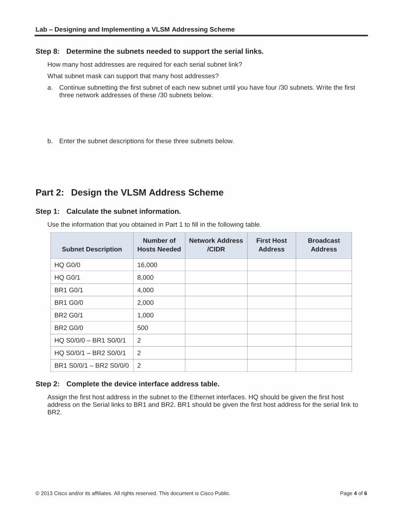
Step 8: Determine the subnets needed to support the serial links.
How many host addresses are required for each serial subnet link?
What subnet mask can support that many host addresses?
a. Continue subnetting the first subnet of each new subnet until you have four /30 subnets. Write the first three network addresses of these /30 subnets below.
b. Enter the subnet descriptions for these three subnets below.
Part 2: Design the VLSM Address Scheme
Step 1: Calculate the subnet information.
Use the information that you obtained in Part 1 to fill in the following table.
Subnet Description Number of
Hosts Needed Network Address
/CIDR First Host Address
Broadcast Address
HQ G0/0 16,000
HQ G0/1 8,000
BR1 G0/1 4,000
BR1 G0/0 2,000
BR2 G0/1 1,000
BR2 G0/0 500
HQ S0/0/0 – BR1 S0/0/1 2
HQ S0/0/1 – BR2 S0/0/1 2
BR1 S0/0/1 – BR2 S0/0/0 2
Step 2: Complete the device interface address table.
Assign the first host address in the subnet to the Ethernet interfaces. HQ should be given the first host address on the Serial links to BR1 and BR2. BR1 should be given the first host address for the serial link to BR2.

Lab – Designing and Implementing a VLSM Addressing Scheme
© 2013 Cisco and/or its affiliates. All rights reserved. This document is Cisco Public. Page 5 of 6
Device Interface IP Address Subnet Mask Device Interface
HQ
G0/0 16,000 Host LAN
G0/1 8,000 Host LAN
S0/0/0 BR1 S0/0/0
S0/0/1 BR2 S0/0/1
BR1
G0/0 2,000 Host LAN
G0/1 4,000 Host LAN
S0/0/0 HQ S0/0/0
S0/0/1 BR2 S0/0/0
BR2
G0/0 500 Host LAN
G0/1 1,000 Host LAN
S0/0/0 BR1 S0/0/1
S0/0/1 HQ S0/0/1
Part 3: Cable and Configure the IPv4 Network In Part 3, you will cable the network topology and configure the three routers using the VLSM address scheme that you developed in Part 2.
Step 1: Cable the network as shown in the topology.
Step 2: Configure basic settings on each router.
a. Assign the device name to the router.
b. Disable DNS lookup to prevent the router from attempting to translate incorrectly entered commands as though they were hostnames.
c. Assign class as the privileged EXEC encrypted password.
d. Assign cisco as the console password and enable login.
e. Assign cisco as the VTY password and enable login.
f. Encrypt the clear text passwords.
g. Create a banner that will warn anyone accessing the device that unauthorized access is prohibited.
Step 3: Configure the interfaces on each router.
a. Assign an IP address and subnet mask to each interface using the table that you completed in Part 2.
b. Configure an interface description for each interface.
c. Set the clocking rate on all DCE serial interfaces to 128000. HQ(config-if)# clock rate 128000
d. Activate the interfaces.

Lab – Designing and Implementing a VLSM Addressing Scheme
© 2013 Cisco and/or its affiliates. All rights reserved. This document is Cisco Public. Page 6 of 6
Step 4: Save the configuration on all devices.
Step 5: Test Connectivity.
a. From HQ, ping BR1’s S0/0/0 interface address.
b. From HQ, ping BR2’s S0/0/1 interface address.
c. From BR1, ping BR2’s S0/0/0 interface address.
d. Troubleshoot connectivity issues if pings were not successful.
Note: Pings to the GigabitEthernet interfaces on other routers will not be successful. The LANs defined for the GigabitEthernet interfaces are simulated. Because no devices are attached to these LANs they will be in down/down state. A routing protocol needs to be in place for other devices to be aware of those subnets. The GigabitEthernet interfaces also need to be in an up/up state before a routing protocol can add the subnets to the routing table. These interfaces will remain in a down/down state until a device is connected to the other end of the Ethernet interface cable. The focus of this lab is on VLSM and configuring the interfaces.
Reflection Can you think of a shortcut for calculating the network addresses of consecutive /30 subnets?
Router Interface Summary Table
Router Interface Summary
Router Model Ethernet Interface #1 Ethernet Interface #2 Serial Interface #1 Serial Interface #2
1800 Fast Ethernet 0/0 (F0/0)
Fast Ethernet 0/1 (F0/1)
Serial 0/0/0 (S0/0/0) Serial 0/0/1 (S0/0/1)
1900 Gigabit Ethernet 0/0 (G0/0)
Gigabit Ethernet 0/1 (G0/1)
Serial 0/0/0 (S0/0/0) Serial 0/0/1 (S0/0/1)
2801 Fast Ethernet 0/0 (F0/0)
Fast Ethernet 0/1 (F0/1)
Serial 0/1/0 (S0/1/0) Serial 0/1/1 (S0/1/1)
2811 Fast Ethernet 0/0 (F0/0)
Fast Ethernet 0/1 (F0/1)
Serial 0/0/0 (S0/0/0) Serial 0/0/1 (S0/0/1)
2900 Gigabit Ethernet 0/0 (G0/0)
Gigabit Ethernet 0/1 (G0/1)
Serial 0/0/0 (S0/0/0) Serial 0/0/1 (S0/0/1)
Note: To find out how the router is configured, look at the interfaces to identify the type of router and how many interfaces the router has. There is no way to effectively list all the combinations of configurations for each router class. This table includes identifiers for the possible combinations of Ethernet and Serial interfaces in the device. The table does not include any other type of interface, even though a specific router may contain one. An example of this might be an ISDN BRI interface. The string in parenthesis is the legal abbreviation that can be used in Cisco IOS commands to represent the interface.

© 2014 Cisco and/or its affiliates. All rights reserved. This document is Cisco Public. Page 1 of 7
Lab – Identifying IPv6 Addresses
Topology
Objectives
Part 1: Identify the Different Types of IPv6 Addresses
Review the different types of IPv6 addresses.
Match the IPv6 address with the correct type.
Part 2: Examine a Host IPv6 Network Interface and Address
Check PC IPv6 network address settings.
Part 3: Practice IPv6 Address Abbreviation
Study and review the rules for IPv6 address abbreviation.
Practice compressing and decompressing IPv6 addresses.
Background / Scenario
With the depletion of the Internet Protocol version 4 (IPv4) network address space and the adoption and transition to IPv6, networking professionals must understand how both IPv4 and IPv6 networks function. Many devices and applications already support IPv6. This includes extensive Cisco device Internetwork Operating System (IOS) support and workstation/server operating system support, such as that found in Windows and Linux.
This lab focuses on IPv6 addresses and the components of the address. In Part 1, you will identify the IPv6 address types, and in Part 2, you will view the IPv6 settings on a PC. In Part 3, you will practice IPv6 address abbreviation.
Required Resources
1 PC (Windows 7 or Vista with Internet access)
Note: The IPv6 protocol is enabled in Windows 7 and Vista by default. The Windows XP operating system
does not enable IPv6 by default and is not recommended for use with this lab. This lab uses Windows 7 PC
hosts.
Part 1: Identify the Different Types of IPv6 Addresses
In Part 1, you will review the characteristics of IPv6 addresses to identify the different types of IPv6 addresses.

Lab – Identifying IPv6 Addresses
© 2014 Cisco and/or its affiliates. All rights reserved. This document is Cisco Public. Page 2 of 7
Step 1: Review the different types of IPv6 addresses.
An IPv6 address is 128 bits long. It is most often presented as 32 hexadecimal characters. Each hexadecimal character is the equivalent of 4 bits (4 x 32 = 128). A non-abbreviated IPv6 host address is shown here:
2001:0DB8:0001:0000:0000:0000:0000:0001
A hextet is the hexadecimal, IPv6 version of an IPv4 octet. An IPv4 address is 4 octets long, separated by dots. An IPv6 address is 8 hextets long, separated by colons.
An IPv4 address is 4 octets and is commonly written or displayed in decimal notation.
255.255.255.255
An IPv6 address is 8 hextets and is commonly written or displayed in hexadecimal notation.
FFFF:FFFF:FFFF:FFFF:FFFF:FFFF:FFFF:FFFF
In an IPv4 address, each individual octet is 8 binary digits (bits). Four octets equals one 32-bit IPv4 address.
11111111 = 255
11111111.11111111.11111111.11111111 = 255.255.255.255
In an IPv6 address, each individual hextet is 16 bits long. Eight hextets equals one 128-bit IPv6 address.
1111111111111111 = FFFF
1111111111111111.1111111111111111.1111111111111111.1111111111111111.
1111111111111111.1111111111111111.1111111111111111.1111111111111111 =
FFFF:FFFF:FFFF:FFFF:FFFF:FFFF:FFFF:FFFF
If we read an IPv6 address starting from the left, the first (or far left) hextet identifies the IPv6 address type. For example, if the IPv6 address has all zeros in the far left hextet, then the address is possibly a loopback address.
0000:0000:0000:0000:0000:0000:0000:0001 = loopback address
::1 = loopback address abbreviated
As another example, if the IPv6 address has FE80 in the first hextet, then the address is a link-local
address.
FE80:0000:0000:0000:C5B7:CB51:3C00:D6CE = link-local address
FE80::C5B7:CB51:3C00:D6CE = link-local address abbreviated
Study the chart below to help you identify the different types of IPv6 address based on the numbers in the
first hextet.

Lab – Identifying IPv6 Addresses
© 2014 Cisco and/or its affiliates. All rights reserved. This document is Cisco Public. Page 3 of 7
First Hextet (Far Left) Type of IPv6 Address
0000 to 00FF Loopback address, any address, unspecified address, or IPv4-compatible
2000 to 3FFF
Global unicast address (a routable address in a range of addresses that is currently being handed out by the Internet Assigned Numbers Authority [IANA])
FE80 to FEBF Link-local (a unicast address which identifies the host computer on the local network)
FC00 to FCFF
Unique-local (a unicast address which can be assigned to a host to identify it as being part of a specific subnet on the local network)
FF00 to FFFF Multicast address
There are other IPv6 address types that are either not yet widely implemented, or have already become deprecated, and are no longer supported. For instance, an anycast address is new to IPv6 and can be used by routers to facilitate load sharing and provide alternate path flexibility if a router becomes unavailable. Only routers should respond to an anycast address. Alternatively, site-local addresses have been deprecated and replaced by unique-local addresses. Site-local addresses were identified by the numbers FEC0 in the initial hextet.
In IPv6 networks, there are no network (wire) addresses or broadcast addresses as there are in IPv4 networks.
Step 2: Match the IPv6 address to its type.
Match the IPv6 addresses to their corresponding address type. Notice that the addresses have been compressed to their abbreviated notation and that the slash network prefix number is not shown. Some answer choices must be used more than once.
IPv6 Address Answer Answer Choices
2001:0DB8:1:ACAD::FE55:6789:B210 1. a. Loopback address
::1 2. b. Global unicast address
FC00:22:A:2::CD4:23E4:76FA 3. c. Link-local address
2033:DB8:1:1:22:A33D:259A:21FE 4. d. Unique-local address
FE80::3201:CC01:65B1 5. e. Multicast address
FF00:: 6.
FF00::DB7:4322:A231:67C 7.
FF02::2 8.
Part 2: Examine a Host IPv6 Network Interface and Address
In Part 2, you will check the IPv6 network settings of your PC to identify your network interface IPv6 address.
Step 1: Check your PC IPv6 network address settings.
a. Verify that the IPv6 protocol is installed and active on your PC-A (check your Local Area Connectionsettings).

Lab – Identifying IPv6 Addresses
© 2014 Cisco and/or its affiliates. All rights reserved. This document is Cisco Public. Page 4 of 7
b. Click the Windows Start button and then Control Panel and change View by: Category to View by: Small icons.
c. Click the Network and Sharing Center icon.
d. On the left side of the window, click Change adapter settings. You should now see icons representing your installed network adapters. Right-click your active network interface (it may be a Local Area Connection or a Wireless Network Connection), and then click Properties.
e. You should now see your Network Connection Properties window. Scroll through the list of items to determine whether IPv6 is present, which indicates that it is installed, and if it is also check marked, which indicates that it is active.
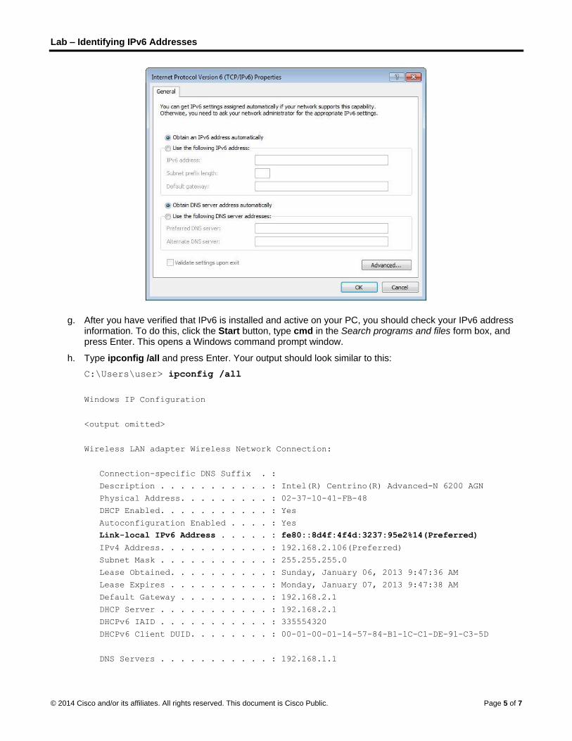
f. Select the item Internet Protocol Version 6 (TCP/IPv6) and click Properties. You should see the IPv6 settings for your network interface. Your IPv6 properties window is likely set to Obtain an IPv6 address automatically. This does not mean that IPv6 relies on the Dynamic Host Configuration Protocol (DHCP). Instead of using DHCP, IPv6 looks to the local router for IPv6 network information and then auto-configures its own IPv6 addresses. To manually configure IPv6, you must provide the IPv6 address, the subnet prefix length, and the default gateway.
Note: The local router can refer host requests for IPv6 information, especially Domain Name System (DNS) information, to a DHCPv6 server on the network.
Lab – Identifying IPv6 Addresses
© 2014 Cisco and/or its affiliates. All rights reserved. This document is Cisco Public. Page 5 of 7
g. After you have verified that IPv6 is installed and active on your PC, you should check your IPv6 address information. To do this, click the Start button, type cmd in the Search programs and files form box, and press Enter. This opens a Windows command prompt window.
h. Type ipconfig /all and press Enter. Your output should look similar to this:
C:\Users\user> ipconfig /all
Windows IP Configuration
<output omitted>
Wireless LAN adapter Wireless Network Connection:
Connection-specific DNS Suffix . :
Description . . . . . . . . . . . : Intel(R) Centrino(R) Advanced-N 6200 AGN
Physical Address. . . . . . . . . : 02-37-10-41-FB-48
DHCP Enabled. . . . . . . . . . . : Yes
Autoconfiguration Enabled . . . . : Yes
Link-local IPv6 Address . . . . . : fe80::8d4f:4f4d:3237:95e2%14(Preferred)
IPv4 Address. . . . . . . . . . . : 192.168.2.106(Preferred)
Subnet Mask . . . . . . . . . . . : 255.255.255.0
Lease Obtained. . . . . . . . . . : Sunday, January 06, 2013 9:47:36 AM
Lease Expires . . . . . . . . . . : Monday, January 07, 2013 9:47:38 AM
Default Gateway . . . . . . . . . : 192.168.2.1
DHCP Server . . . . . . . . . . . : 192.168.2.1
DHCPv6 IAID . . . . . . . . . . . : 335554320
DHCPv6 Client DUID. . . . . . . . : 00-01-00-01-14-57-84-B1-1C-C1-DE-91-C3-5D
DNS Servers . . . . . . . . . . . : 192.168.1.1

Lab – Identifying IPv6 Addresses
© 2014 Cisco and/or its affiliates. All rights reserved. This document is Cisco Public. Page 6 of 7
8.8.4.4
<output omitted>
i. You can see from the output that the client PC has an IPv6 link-local address with a randomly generated interface ID. What does it indicate about the network regarding IPv6 global unicast address, IPv6 unique-local address, or IPv6 gateway address?
j. What kind of IPv6 addresses did you find when using ipconfig /all?
Part 3: Practice IPv6 Address Abbreviation
In Part 3, you will study and review rules for IPv6 address abbreviation to correctly compress and decompress IPv6 addresses.
Step 1: Study and review the rules for IPv6 address abbreviation.
Rule 1: In an IPv6 address, a string of four zeros (0s) in a hextet can be abbreviated as a single zero.
2001:0404:0001:1000:0000:0000:0EF0:BC00
2001:0404:0001:1000:0:0:0EF0:BC00 (abbreviated with single zeros)
Rule 2: In an IPv6 address, the leading zeros in each hextet can be omitted, trailing zeros cannot be omitted.
2001:0404:0001:1000:0000:0000:0EF0:BC00
2001:404:1:1000:0:0:EF0:BC00 (abbreviated with leading zeros omitted)
Rule 3: In an IPv6 address, a single continuous string of four or more zeros can be abbreviated as a double colon (::). The double colon abbreviation can only be used one time in an IP address.
2001:0404:0001:1000:0000:0000:0EF0:BC00
2001:404:1:1000::EF0:BC00 (abbreviated with leading zeroes omitted and continuous zeros
replaced with a double colon)
The image below illustrates these rules of IPv6 address abbreviation:

Lab – Identifying IPv6 Addresses
© 2014 Cisco and/or its affiliates. All rights reserved. This document is Cisco Public. Page 7 of 7
Step 2: Practice compressing and decompressing IPv6 addresses.
Using the rules of IPv6 address abbreviation, either compress or decompress the following addresses:
1) 2002:0EC0:0200:0001:0000:04EB:44CE:08A2
2) FE80:0000:0000:0001:0000:60BB:008E:7402
3) FE80::7042:B3D7:3DEC:84B8
4) FF00::
5) 2001:0030:0001:ACAD:0000:330E:10C2:32BF
Reflection
1. How do you think you must support IPv6 in the future?
2. Do you think IPv4 networks continue on, or will everyone eventually switch over to IPv6? How long do you think it will take?

©
L
T
© 2013 Cisco and
Lab – Te
Topology
d/or its affiliates.
esting N
All rights reserve
Network
ed. This docume
Connec
ent is Cisco Publi
ctivity wi
ic.
ith Ping and Tra
P
aceroute
Page 1 of 15
e

Lab – Testing Network Connectivity with Ping and Traceroute
© 2013 Cisco and/or its affiliates. All rights reserved. This document is Cisco Public. Page 2 of 15
Addressing Table
Device Interface IP Address Subnet Mask Default Gateway
LOCAL G0/1 192.168.1.1 255.255.255.0 N/A
S0/0/0 (DCE) 10.1.1.1 255.255.255.252 N/A
ISP S0/0/0 10.1.1.2 255.255.255.252 N/A
S0/0/1 (DCE) 10.2.2.2 255.255.255.252 N/A
REMOTE G0/1 192.168.3.1 255.255.255.0 N/A
S0/0/1 10.2.2.1 255.255.255.252 N/A
S1 VLAN 1 192.168.1.11 255.255.255.0 192.168.1.1
S3 VLAN 1 192.168.3.11 255.255.255.0 192.168.3.1
PC-A NIC 192.168.1.3 255.255.255.0 192.168.1.1
PC-C NIC 192.168.3.3 255.255.255.0 192.168.3.1
Objectives Part 1: Build and Configure the Network
Cable the network.
Configure the PCs.
Configure the routers.
Configure the switches.
Part 2: Use Ping Command for Basic Network Testing
Use ping from a PC.
Use ping from Cisco devices.
Part 3: Use Tracert and Traceroute Commands for Basic Network Testing
Use tracert from a PC.
Use traceroute from Cisco devices.
Part 4: Troubleshoot the Topology
Background / Scenario Ping and traceroute are two tools that are indispensable when testing TCP/IP network connectivity. Ping is a network administration utility used to test the reachability of a device on an IP network. This utility also measures the round-trip time for messages sent from the originating host to a destination computer. The ping utility is available on Windows, Unix-like operating systems (OS), and the Cisco Internetwork Operating System (IOS).
The traceroute utility is a network diagnostic tool for displaying the route and measuring the transit delays of packets travelling an IP network. The tracert utility is available on Windows, and a similar utility, traceroute, is available on Unix-like OS and Cisco IOS.
In this lab, the ping and traceroute commands are examined and command options are explored to modify the command behavior. Cisco devices and PCs are used in this lab for command exploration. Cisco routers

Lab – Testing Network Connectivity with Ping and Traceroute
© 2013 Cisco and/or its affiliates. All rights reserved. This document is Cisco Public. Page 3 of 15
will use Enhanced Interior Gateway Routing Protocol (EIGRP) to route packets between networks. The necessary Cisco device configurations are provided in this lab.
Note: The routers used with CCNA hands-on labs are Cisco 1941 Integrated Services Routers (ISRs) with Cisco IOS Release 15.2(4)M3 (universalk9 image). The switches used are Cisco Catalyst 2960s with Cisco IOS Release 15.0(2) (lanbasek9 image). Other routers, switches and Cisco IOS versions can be used. Depending on the model and Cisco IOS version, the commands available and output produced might vary from what is shown in the labs. Refer to the Router Interface Summary Table at the end of this lab for the correct interface identifiers. Note: Make sure that the routers and switches have been erased and have no startup configurations. If you are unsure, contact your instructor.
Required Resources 3 Routers (Cisco 1941 with Cisco IOS Release 15.2(4)M3 universal image or comparable)
2 Switches (Cisco 2960 with Cisco IOS Release 15.0(2) lanbasek9 image or comparable)
2 PCs (Windows 7, Vista, or XP with terminal emulation program, such as Tera Term)
Console cables to configure the Cisco IOS devices via the console ports
Ethernet and serial cables as shown in the topology
Part 1: Build and Configure the Network In Part 1, you will set up the network in the topology and configure the PCs and Cisco devices. The initial configurations for the routers and switches are provided for your reference. In this topology, EIGRP is used to route packets between networks.
Step 1: Cable the network as shown in the topology.
Step 2: Erase the configurations on the routers and switches, and reload the devices.
Step 3: Configure PC IP addresses and default gateways according to the Addressing Table.
Step 4: Configure the LOCAL, ISP, and REMOTE routers using the initial configurations provided below.
At the switch or router global config mode prompt, copy and paste the configuration for each device. Save the configuration to startup-config.
Initial configurations for the LOCAL router: hostname LOCAL
no ip domain-lookup
interface s0/0/0
ip address 10.1.1.1 255.255.255.252
clock rate 56000
no shutdown
interface g0/1
ip add 192.168.1.1 255.255.255.0
no shutdown
router eigrp 1
network 10.1.1.0 0.0.0.3

Lab – Testing Network Connectivity with Ping and Traceroute
© 2013 Cisco and/or its affiliates. All rights reserved. This document is Cisco Public. Page 4 of 15
network 192.168.1.0 0.0.0.255
no auto-summary
Initial configurations for ISP: hostname ISP
no ip domain-lookup
interface s0/0/0
ip address 10.1.1.2 255.255.255.252
no shutdown
interface s0/0/1
ip add 10.2.2.2 255.255.255.252
clock rate 56000
no shutdown
router eigrp 1
network 10.1.1.0 0.0.0.3
network 10.2.2.0 0.0.0.3
no auto-summary
end
Initial configurations for REMOTE: hostname REMOTE
no ip domain-lookup
interface s0/0/1
ip address 10.2.2.1 255.255.255.252
no shutdown
interface g0/1
ip add 192.168.3.1 255.255.255.0
no shutdown
router eigrp 1
network 10.2.2.0 0.0.0.3
network 192.168.3.0 0.0.0.255
no auto-summary
end
Step 5: Configure the S1 and S3 switches with the initial configurations.
Initial configurations for S1: hostname S1
no ip domain-lookup
interface vlan 1
ip add 192.168.1.11 255.255.255.0
no shutdown
exit
ip default-gateway 192.168.1.1
end
Initial configurations for S3:

Lab – Testing Network Connectivity with Ping and Traceroute
© 2013 Cisco and/or its affiliates. All rights reserved. This document is Cisco Public. Page 5 of 15
hostname S3
no ip domain-lookup
interface vlan 1
ip add 192.168.3.11 255.255.255.0
no shutdown
exit
ip default-gateway 192.168.3.1
end
Step 6: Configure an IP host table on the LOCAL router.
The IP host table allows you to use a hostname to connect to a remote device rather than an IP address. The host table provides name resolution for the device with the following configurations. Copy and paste the following configurations for the LOCAL router. The configurations will allow you to use the hostnames for ping and traceroute commands on the LOCAL router.
ip host REMOTE 10.2.2.1 192.168.3.1
ip host ISP 10.1.1.2 10.2.2.2
ip host LOCAL 192.168.1.1 10.1.1.1
ip host PC-C 192.168.3.3
ip host PC-A 192.168.1.3
ip host S1 192.168.1.11
ip host S3 192.168.3.11
end
Part 2: Use Ping Command for Basic Network Testing In Part 2 of this lab, use the ping command to verify end-to-end connectivity. Ping operates by sending Internet Control Message Protocol (ICMP) echo request packets to the target host and then waiting for an ICMP response. It can record the round trip time and any packet loss.
You will examine the results with the ping command and the additional ping options that are available on Windows-based PCs and Cisco devices.
Step 1: Test network connectivity from the LOCAL network using PC-A.
All the pings from PC-A to other devices in the topology should be successful. If they are not, check the topology and the cabling, as well as the configuration of the Cisco devices and the PCs.
a. Ping from PC-A to its default gateway (LOCAL’s GigabitEthernet 0/1 interface).
C:\Users\User1> ping 192.168.1.1 Pinging 192.168.1.1 with 32 bytes of data:
Reply from 192.168.1.1: bytes=32 time<1ms TTL=255
Reply from 192.168.1.1: bytes=32 time<1ms TTL=255
Reply from 192.168.1.1: bytes=32 time<1ms TTL=255
Reply from 192.168.1.1: bytes=32 time<1ms TTL=255
Ping statistics for 192.168.1.1:
Packets: Sent = 4, Received = 4, Lost = 0 (0% loss),
Approximate round trip times in milli-seconds:
Minimum = 0ms, Maximum = 0ms, Average = 0ms
Lab – Testing Network Connectivity with Ping and Traceroute
© 2013 Cisco and/or its affiliates. All rights reserved. This document is Cisco Public. Page 6 of 15
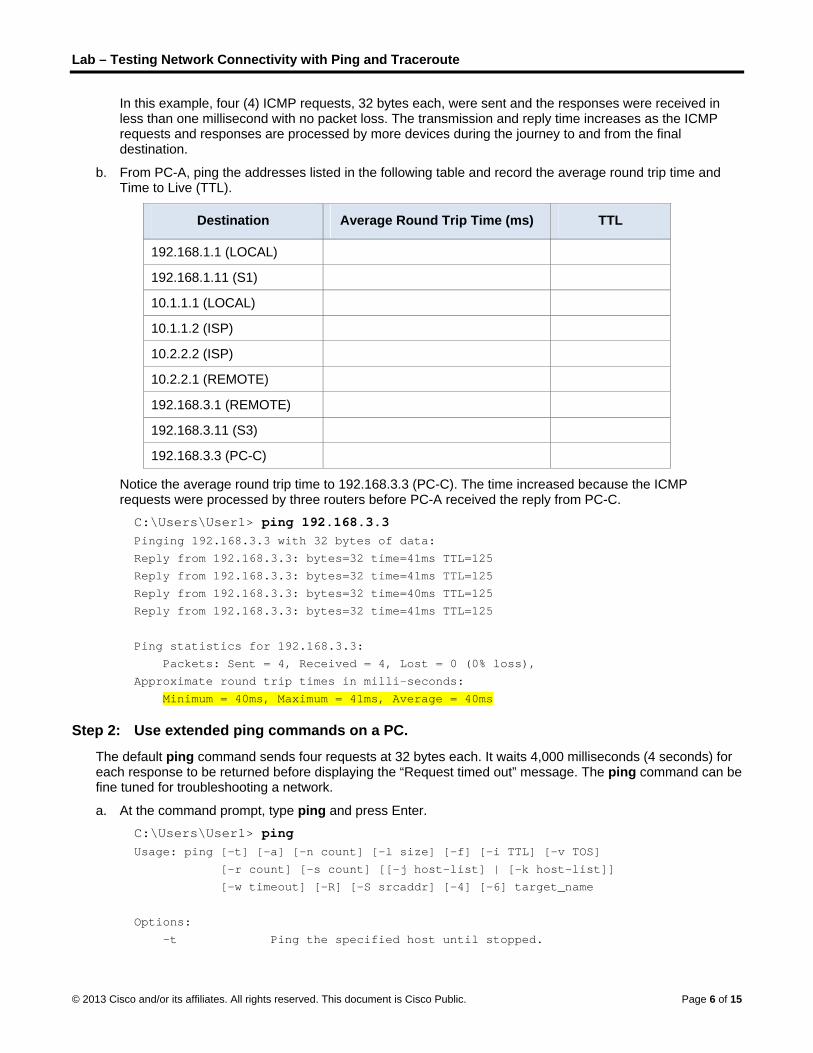
In this example, four (4) ICMP requests, 32 bytes each, were sent and the responses were received in less than one millisecond with no packet loss. The transmission and reply time increases as the ICMP requests and responses are processed by more devices during the journey to and from the final destination.
b. From PC-A, ping the addresses listed in the following table and record the average round trip time and Time to Live (TTL).
Destination Average Round Trip Time (ms) TTL
192.168.1.1 (LOCAL)
192.168.1.11 (S1)
10.1.1.1 (LOCAL)
10.1.1.2 (ISP)
10.2.2.2 (ISP)
10.2.2.1 (REMOTE)
192.168.3.1 (REMOTE)
192.168.3.11 (S3)
192.168.3.3 (PC-C)
Notice the average round trip time to 192.168.3.3 (PC-C). The time increased because the ICMP requests were processed by three routers before PC-A received the reply from PC-C.
C:\Users\User1> ping 192.168.3.3 Pinging 192.168.3.3 with 32 bytes of data:
Reply from 192.168.3.3: bytes=32 time=41ms TTL=125
Reply from 192.168.3.3: bytes=32 time=41ms TTL=125
Reply from 192.168.3.3: bytes=32 time=40ms TTL=125
Reply from 192.168.3.3: bytes=32 time=41ms TTL=125
Ping statistics for 192.168.3.3:
Packets: Sent = 4, Received = 4, Lost = 0 (0% loss),
Approximate round trip times in milli-seconds:
Minimum = 40ms, Maximum = 41ms, Average = 40ms
Step 2: Use extended ping commands on a PC.
The default ping command sends four requests at 32 bytes each. It waits 4,000 milliseconds (4 seconds) for each response to be returned before displaying the “Request timed out” message. The ping command can be fine tuned for troubleshooting a network.
a. At the command prompt, type ping and press Enter.
C:\Users\User1> ping Usage: ping [-t] [-a] [-n count] [-l size] [-f] [-i TTL] [-v TOS]
[-r count] [-s count] [[-j host-list] | [-k host-list]]
[-w timeout] [-R] [-S srcaddr] [-4] [-6] target_name
Options:
-t Ping the specified host until stopped.

Lab – Testing Network Connectivity with Ping and Traceroute
© 2013 Cisco and/or its affiliates. All rights reserved. This document is Cisco Public. Page 7 of 15
To see statistics and continue - type Control-Break;
To stop - type Control-C.
-a Resolve addresses to hostnames.
-n count Number of echo requests to send.
-l size Send buffer size.
-f Set Don't Fragment flag in packet (IPv4-only).
-i TTL Time To Live.
-v TOS Type Of Service (IPv4-only. This setting has been deprecated
and has no effect on the type of service field in the IP Header).
-r count Record route for count hops (IPv4-only).
-s count Timestamp for count hops (IPv4-only).
-j host-list Loose source route along host-list (IPv4-only).
-k host-list Strict source route along host-list (IPv4-only).
-w timeout Timeout in milliseconds to wait for each reply.
-R Use routing header to test reverse route also (IPv6-only).
-S srcaddr Source address to use.
-4 Force using IPv4.
-6 Force using IPv6.
b. Using the –t option, ping PC-C to verify that PC-C is reachable.
C:\Users\User1> ping –t 192.168.3.3 Reply from 192.168.3.3: bytes=32 time=41ms TTL=125
Reply from 192.168.3.3: bytes=32 time=40ms TTL=125
To illustrate the results when a host is unreachable, disconnect the cable between the REMOTE router and the S3 switch, or shut down the GigabitEthernet 0/1 interface on the REMOTE router.
Reply from 192.168.3.3: bytes=32 time=41ms TTL=125
Reply from 192.168.1.3: Destination host unreachable.
Reply from 192.168.1.3: Destination host unreachable.
While the network is functioning correctly, the ping command can determine whether the destination responded and how long it took to receive a reply from the destination. If a network connectivity problem exists, the ping command displays an error message.
c. Reconnect the Ethernet cable or enable the GigabitEthernet interface on the REMOTE router (using the no shutdown command) before moving onto the next step. After about 30 seconds, the ping should be successful again.
Request timed out.
Request timed out.
Request timed out.
Request timed out.
Reply from 192.168.3.3: bytes=32 time=41ms TTL=125
Reply from 192.168.3.3: bytes=32 time=40ms TTL=125
d. Press Ctrl+C to stop the ping command.
Step 3: Test network connectivity from the LOCAL network using Cisco devices.
The ping command is also available on Cisco devices. In this step, the ping command is examined using the LOCAL router and the S1 switch.
a. Ping PC-C on the REMOTE network using the IP address of 192.168.3.3 from the LOCAL router.
LOCAL# ping 192.168.3.3

Lab – Testing Network Connectivity with Ping and Traceroute
© 2013 Cisco and/or its affiliates. All rights reserved. This document is Cisco Public. Page 8 of 15
Type escape sequence to abort.
Sending 5, 100-byte ICMP Echos to 192.168.3.3, timeout is 2 seconds:
!!!!!
Success rate is 100 percent (5/5), round-trip min/avg/max = 60/64/68 ms
The exclamation point (!) indicates that the ping was successful from the LOCAL router to PC-C. The round trip takes an average of 64 ms with no packet loss, as indicated by a 100% success rate.
b. Because a local host table was configured on the LOCAL router, you can ping PC-C on the REMOTE network using the hostname configured from the LOCAL router.
LOCAL# ping PC-C Type escape sequence to abort.
Sending 5, 100-byte ICMP Echos to 192.168.3.3, timeout is 2 seconds:
!!!!!
Success rate is 100 percent (5/5), round-trip min/avg/max = 60/63/64 ms
c. There are more options available for the ping command. At the CLI, type ping and press Enter. Input 192.168.3.3 or PC-C for the Target IP address. Press Enter to accept the default value for other options.
LOCAL# ping Protocol [ip]:
Target IP address: PC-C
Repeat count [5]:
Datagram size [100]:
Timeout in seconds [2]:
Extended commands [n]:
Sweep range of sizes [n]:
Type escape sequence to abort.
Sending 5, 100-byte ICMP Echos to 192.168.3.3, timeout is 2 seconds:
!!!!!
Success rate is 100 percent (5/5), round-trip min/avg/max = 60/63/64 ms
d. You can use an extended ping to observe when there is a network issue. Start the ping command to 192.168.3.3 with a repeat a count of 500. Then, disconnect the cable between the REMOTE router and the S3 switch or shut down the GigabitEthernet 0/1 interface on the REMOTE router.
Reconnect the Ethernet cable or enable the GigabitEthernet interface on the REMOTE router after the exclamation points (!) have replaced by the letter U and periods (.). After about 30 seconds, the ping should be successful again. Press Ctrl+Shift+6 to stop the ping command if desired.
LOCAL# ping Protocol [ip]:
Target IP address: 192.168.3.3
Repeat count [5]: 500
Datagram size [100]:
Timeout in seconds [2]:
Extended commands [n]:
Sweep range of sizes [n]:
Type escape sequence to abort.
Sending 500, 100-byte ICMP Echos to 192.168.3.3, timeout is 2 seconds:
!!!!!!!!!!!!!!!!!!!!!!!!!!!!!!!!!!!!!!!!!!!!!!!!!!!!!!!!!!!!!!!!!!!!!!
!!!!!!!!!!!!!!!!!!!!!!!!!!!!!!!!!!!!!!!!!!!!!!!!!!!!!!!!!!!!!!!!!!!!!!
!!!!!!!!!!!!!!!!!!!!!!!!!!!!!!!!!!!!!!!!!!!!!!!!!!!!!U................
....!!!!!!!!!!!!!!!!!!!!!!!!!!!!!!!!!!!!!!!!!!!!!!!!!!!!!!!!!!!!!!!!!!

Lab – Testing Network Connectivity with Ping and Traceroute
© 2013 Cisco and/or its affiliates. All rights reserved. This document is Cisco Public. Page 9 of 15
!!!!!!!!!!!!!!!!!!!!!!!!!!!!!!!!!!!!!!!!!!!!!!!!!!!!!!!!!!!!!!!!!!!!!!
!!!!!!!!!!!!!!!!!!!!!!!!!!!!!!!!!!!!!!!!!!!!!!!!!!!!!!!!!!!!!!!!!!!!!!
!!!!!!!!!!!!!!!!!!!!!!!!!!!!!!!!!!!!!!!!!!!!!!!!!!!!!!!!!!!!!!!!!!!!!!
!!!!!!!!!!
Success rate is 95 percent (479/500), round-trip min/avg/max = 60/63/72 ms
The letter U in the results indicates that a destination is unreachable. An error protocol data unit (PDU) was received by the LOCAL router. Each period (.) in the output indicates that the ping timed out while waiting for a reply from PC-C. In this example, 5% of the packets were lost during the simulated network outage.
Note: You can also use the following command for the same results:
LOCAL# ping 192.168.3.3 repeat 500
or LOCAL# ping PC-C repeat 500
e. You can also test network connectivity with a switch. In this example, the S1 switch pings the S3 switch on the REMOTE network.
S1# ping 192.168.3.11 Type escape sequence to abort.
Sending 5, 100-byte ICMP Echos to 192.168.3.11, timeout is 2 seconds:
!!!!!
Success rate is 100 percent (5/5), round-trip min/avg/max = 67/67/68 ms
The ping command is extremely useful when troubleshooting network connectivity. However, ping cannot indicate the location of problem when a ping is not successful. The tracert (or traceroute) command can display network latency and path information.
Part 3: Use Tracert and Traceroute Commands for Basic Network Testing The commands for tracing routes can be found on PCs and network devices. For a Windows-based PC, the tracert command uses ICMP messages to trace the path to the final destination. The traceroute command utilizes the User Datagram Protocol (UDP) datagrams for tracing routes to the final destination for Cisco devices and other Unix-like PCs.
In Part 3, you will examine the traceroute commands and determine the path that a packet travels to its final destination. You will use the tracert command from the Windows PCs and the traceroute command from the Cisco devices. You will also examine the options that are available for fine tuning the traceroute results.
Step 1: Use the tracert command from PC-A to PC-C.
a. At the command prompt, type tracert 192.168.3.3.
C:\Users\User1> tracert 192.168.3.3 Tracing route to PC-C [192.168.3.3]
Over a maximum of 30 hops:
1 <1 ms <1 ms <1 ms 192.168.1.1
2 24 ms 24 ms 24 ms 10.1.1.2
3 48 ms 48 ms 48 ms 10.2.2.1
4 59 ms 59 ms 59 ms PC-C [192.168.3.3]
Trace complete.

Lab – Testing Network Connectivity with Ping and Traceroute
© 2013 Cisco and/or its affiliates. All rights reserved. This document is Cisco Public. Page 10 of 15
The tracert results indicates the path from PC-A to PC-C is from PC-A to LOCAL to ISP to REMOTE to PC-C. The path to PC-C traveled through three router hops to the final destination of PC-C.
Step 2: Explore additional options for the tracert command.
a. At the command prompt, type tracert and press Enter.
C:\Users\User1> tracert
Usage: tracert [-d] [-h maximum_hops] [-j host-list] [-w timeout]
[-R] [-S srcaddr] [-4] [-6] target_name
Options:
-d Do not resolve addresses to hostnames.
-h maximum_hops Maximum number of hops to search for target.
-j host-list Loose source route along host-list (IPv4-only).
-w timeout Wait timeout milliseconds for each reply.
-R Trace round-trip path (IPv6-only).
-S srcaddr Source address to use (IPv6-only).
-4 Force using IPv4.
-6 Force using IPv6.
b. Use the -d option. Notice that the IP address of 192.168.3.3 is not resolved as PC-C.
C:\Users\User1> tracert –d 192.168.3.3 Tracing route to 192.168.3.3 over a maximum of 30 hops:
1 <1 ms <1 ms <1 ms 192.168.1.1
2 24 ms 24 ms 24 ms 10.1.1.2
3 48 ms 48 ms 48 ms 10.2.2.1
4 59 ms 59 ms 59 ms 192.168.3.3
Trace complete.
Step 3: Use the traceroute command from the LOCAL router to PC-C.
a. At the command prompt, type traceroute 192.168.3.3 or traceroute PC-C on the LOCAL router. The hostnames are resolved because a local IP host table was configured on the LOCAL router.
LOCAL# traceroute 192.168.3.3 Type escape sequence to abort.
Tracing the route to PC-C (192.168.3.3)
VRF info: (vrf in name/id, vrf out name/id)
1 ISP (10.1.1.2) 16 msec 16 msec 16 msec
2 REMOTE (10.2.2.1) 28 msec 32 msec 28 msec
3 PC-C (192.168.3.3) 32 msec 28 msec 32 msec
LOCAL# traceroute PC-C Type escape sequence to abort.
Tracing the route to PC-C (192.168.3.3)
VRF info: (vrf in name/id, vrf out name/id)
1 ISP (10.1.1.2) 16 msec 16 msec 16 msec
2 REMOTE (10.2.2.1) 28 msec 32 msec 28 msec

Lab – Testing Network Connectivity with Ping and Traceroute
© 2013 Cisco and/or its affiliates. All rights reserved. This document is Cisco Public. Page 11 of 15
3 PC-C (192.168.3.3) 32 msec 32 msec 28 msec
Step 4: Use the traceroute command from the S1 switch to PC-C.
a. On the S1 switch, type traceroute 192.168.3.3. The hostnames are not displayed in the traceroute results because a local IP host table was not configured on this switch.
S1# traceroute 192.168.3.3 Type escape sequence to abort.
Tracing the route to 192.168.3.3
VRF info: (vrf in name/id, vrf out name/id)
1 192.168.1.1 1007 msec 0 msec 0 msec
2 10.1.1.2 17 msec 17 msec 16 msec
3 10.2.2.1 34 msec 33 msec 26 msec
4 192.168.3.3 33 msec 34 msec 33 msec
The traceroute command has additional options. You can use the ? or just press Enter after typing traceroute at the prompt to explore these options.
The following link provides more information regarding the ping and traceroute commands for a Cisco device:
http://www.cisco.com/en/US/products/sw/iosswrel/ps1831/products_tech_note09186a00800a6057.shtml
Part 4: Troubleshoot the Topology
Step 1: Erase the configurations on the REMOTE router.
Step 2: Reload the REMOTE router.
Step 3: Copy and paste the following configuration into the REMOTE router. hostname REMOTE
no ip domain-lookup
interface s0/0/1
ip address 10.2.2.1 255.255.255.252
no shutdown
interface g0/1
ip add 192.168.8.1 255.255.255.0
no shutdown
router eigrp 1
network 10.2.2.0 0.0.0.3
network 192.168.3.0 0.0.0.255
no auto-summary
end
Step 4: From the LOCAL network, use ping and tracert or traceroute commands to troubleshoot and correct the problem on the REMOTE network.
a. Use the ping and tracert commands from PC-A.

Lab – Testing Network Connectivity with Ping and Traceroute
© 2013 Cisco and/or its affiliates. All rights reserved. This document is Cisco Public. Page 12 of 15
You can use the tracert command to determine end-to-end network connectivity. This tracert result indicates that PC-A can reach its default gateway of 192.168.1.1, but PC-A does not have network connectivity with PC-C.
C:\Users\User1> tracert 192.168.3.3
Tracing route to 192.168.3.3 over a maximum of 30 hops
1 <1 ms <1 ms <1 ms 192.168.1.1
2 192.168.1.1 reports: Destination host unreachable.
Trace complete.
One way to locate the network issue is to ping each hop in the network to PC-C. First determine if PC-A can reach the ISP router Serial 0/0/1 interface with an IP address of 10.2.2.2.
C:\Users\Utraser1> ping 10.2.2.2
Pinging 10.2.2.2 with 32 bytes of data:
Reply from 10.2.2.2: bytes=32 time=41ms TTL=254
Reply from 10.2.2.2: bytes=32 time=41ms TTL=254
Reply from 10.2.2.2: bytes=32 time=41ms TTL=254
Reply from 10.2.2.2: bytes=32 time=41ms TTL=254
Ping statistics for 10.2.2.2:
Packets: Sent = 4, Received = 4, Lost = 0 (0% loss),
Approximate round trip times in milli-seconds:
Minimum = 20ms, Maximum = 21ms, Average = 20ms
The ping was successful to the ISP router. The next hop in the network is the REMOTE router. Ping the REMOTE router Serial 0/0/1 interface with an IP address of 10.2.2.1.
C:\Users\User1> ping 10.2.2.1
Pinging 10.2.2.1 with 32 bytes of data:
Reply from 10.2.2.1: bytes=32 time=41ms TTL=253
Reply from 10.2.2.1: bytes=32 time=41ms TTL=253
Reply from 10.2.2.1: bytes=32 time=41ms TTL=253
Reply from 10.2.2.1: bytes=32 time=41ms TTL=253
Ping statistics for 10.2.2.1:
Packets: Sent = 4, Received = 4, Lost = 0 (0% loss),
Approximate round trip times in milli-seconds:
Minimum = 40ms, Maximum = 41ms, Average = 40ms
PC-A can reach the REMOTE router. Based on the successful ping results from PC-A to the REMOTE router, the network connectivity issue is with 192.168.3.0/24 network. Ping the default gateway to PC-C, which is the GigabitEthernet 0/1 interface of the REMOTE router.
C:\Users\User1> ping 192.168.3.1
Pinging 192.168.3.1 with 32 bytes of data:
Reply from 192.168.1.1: Destination host unreachable.
Reply from 192.168.1.1: Destination host unreachable.
Reply from 192.168.1.1: Destination host unreachable.

Lab – Testing Network Connectivity with Ping and Traceroute
© 2013 Cisco and/or its affiliates. All rights reserved. This document is Cisco Public. Page 13 of 15
Reply from 192.168.1.1: Destination host unreachable.
Ping statistics for 192.168.3.1:
Packets: Sent = 4, Received = 4, Lost = 0 (0% loss),
PC-A cannot reach the GigabitEthernet 0/1 interface of the REMOTE router, as displayed by the results from the ping command.
The S3 switch can also be pinged from PC-A to verify the location of the networking connectivity issue by typing ping 192.168.3.11 at the command prompt. Because PC-A cannot reach GigabitEthernet 0/1 of the REMOTE router, PC-A probably cannot ping the S3 switch successfully, as indicated by the results below.
C:\Users\User1> ping 192.168.3.11
Pinging 192.168.3.11 with 32 bytes of data:
Reply from 192.168.1.1: Destination host unreachable.
Reply from 192.168.1.1: Destination host unreachable.
Reply from 192.168.1.1: Destination host unreachable.
Reply from 192.168.1.1: Destination host unreachable.
Ping statistics for 192.168.3.11:
Packets: Sent = 4, Received = 4, Lost = 0 (0% loss),
The tracert and ping results conclude that PC-A can reach the LOCAL, ISP, and REMOTE routers, but not PC-C or the S3 switch, nor the default gateway for PC-C.
b. Use the show commands to examine the running configurations for the the REMOTE router.
REMOTE# show ip interface brief Interface IP-Address OK? Method Status Protocol
Embedded-Service-Engine0/0 unassigned YES unset administratively down down
GigabitEthernet0/0 unassigned YES unset administratively down down
GigabitEthernet0/1 192.168.8.1 YES manual up up
Serial0/0/0 unassigned YES unset administratively down down
Serial0/0/1 10.2.2.1 YES manual up up
REMOTE# show run <output omitted>
interface GigabitEthernet0/0
no ip address
shutdown
duplex auto
speed auto
!
interface GigabitEthernet0/1
ip address 192.168.8.1 255.255.255.0
duplex auto
speed auto
!
interface Serial0/0/0
no ip address
shutdown

Lab – Testing Network Connectivity with Ping and Traceroute
© 2013 Cisco and/or its affiliates. All rights reserved. This document is Cisco Public. Page 14 of 15
clock rate 2000000
!
interface Serial0/0/1
ip address 10.2.2.1 255.255.255.252
<output omitted>
The outputs of the show run and show ip interface brief commands indicate that the GigabitEthernet 0/1 interface is up/up, but was configured with an incorrect IP address.
c. Correct the IP address for GigabitEthernet 0/1.
REMOTE# configure terminal Enter configuration commands, one per line. End with CNTL/Z.
REMOTE(config)# interface GigabitEthernet 0/1
REMOTE(config-if)# ip address 192.168.3.1 255.255.255.0
d. Verify that PC-A can ping and tracert to PC-C.
C:\Users\User1> ping 192.168.3.3 Pinging 192.168.3.3 with 32 bytes of data:
Reply from 192.168.3.3: bytes=32 time=44ms TTL=125
Reply from 192.168.3.3: bytes=32 time=41ms TTL=125
Reply from 192.168.3.3: bytes=32 time=40ms TTL=125
Reply from 192.168.3.3: bytes=32 time=41ms TTL=125
Ping statistics for 192.168.3.3:
Packets: Sent = 4, Received = 4, Lost = 0 (0% loss),
Approximate round trip times in milli-seconds:
Minimum = 40ms, Maximum = 44ms, Average = 41ms
C:\Users\User1> tracert 192.168.3.3
Tracing route to PC-C [192.168.3.3]
Over a maximum of 30 hops:
1 <1 ms <1 ms <1 ms 192.168.1.1
2 24 ms 24 ms 24 ms 10.1.1.2
3 48 ms 48 ms 48 ms 10.2.2.1
4 59 ms 59 ms 59 ms PC-C [192.168.3.3]
Trace complete.
Note: This can also be accomplished using ping and traceroute commands from the CLI on the the LOCAL router and the S1 switch after verifying that there are no network connectivity issues on the 192.168.1.0/24 network.
Reflection 1. What could prevent ping or traceroute responses from reaching the originating device beside network
connectivity issues?

Lab – Testing Network Connectivity with Ping and Traceroute
© 2013 Cisco and/or its affiliates. All rights reserved. This document is Cisco Public. Page 15 of 15
2. If you ping a non-existent address on the remote network, such as 192.168.3.4, what is the message displayed by the ping command? What does this mean? If you ping a valid host address and receive this response, what should you check?
3. If you ping an address that does not exist in any network in your topology, such as 192.168.5.3, from a Windows-based PC, what is the message displayed by the ping command? What does this message indicate?
Router Interface Summary Table
Router Interface Summary
Router Model Ethernet Interface #1 Ethernet Interface #2 Serial Interface #1 Serial Interface #2
1800 Fast Ethernet 0/0 (F0/0)
Fast Ethernet 0/1 (F0/1)
Serial 0/0/0 (S0/0/0) Serial 0/0/1 (S0/0/1)
1900 Gigabit Ethernet 0/0 (G0/0)
Gigabit Ethernet 0/1 (G0/1)
Serial 0/0/0 (S0/0/0) Serial 0/0/1 (S0/0/1)
2801 Fast Ethernet 0/0 (F0/0)
Fast Ethernet 0/1 (F0/1)
Serial 0/1/0 (S0/1/0) Serial 0/1/1 (S0/1/1)
2811 Fast Ethernet 0/0 (F0/0)
Fast Ethernet 0/1 (F0/1)
Serial 0/0/0 (S0/0/0) Serial 0/0/1 (S0/0/1)
2900 Gigabit Ethernet 0/0 (G0/0)
Gigabit Ethernet 0/1 (G0/1)
Serial 0/0/0 (S0/0/0) Serial 0/0/1 (S0/0/1)
Note: To find out how the router is configured, look at the interfaces to identify the type of router and how many interfaces the router has. There is no way to effectively list all the combinations of configurations for each router class. This table includes identifiers for the possible combinations of Ethernet and Serial interfaces in the device. The table does not include any other type of interface, even though a specific router may contain one. An example of this might be an ISDN BRI interface. The string in parenthesis is the legal abbreviation that can be used in Cisco IOS commands to represent the interface.

©
L
T
O
B
© 2013 Cisco and
Lab - Us
Topology
ObjectivesPart 1: (O
Part 2: Ca
Start
Locat
Part 3: Ca
Start
Locat
Expla
BackgrounWiresharkanalysis, snetwork, taccording
Wiresharkcourses foWiresharkpacket IP
d/or its affiliates.
sing Wir
Optional) Dow
apture and A
and stop data
te the IP and
apture and A
and stop data
te the IP and
ain why MAC
nd / Scenark is a softwaresoftware and the sniffer "cag to the appro
k is a useful toor data analysk, although it addresses a
All rights reserve
eshark t
wnload and I
Analyze Loca
a capture of p
MAC address
Analyze Rem
a capture of p
MAC address
addresses fo
rio e protocol anaprotocol deve
aptures" eachpriate RFC o
ool for anyonesis and troublmay already nd Ethernet fr
ed. This docume
to View
Install Wires
al ICMP Data
ping traffic to l
s information
ote ICMP Da
ping traffic to r
s information
r remote host
alyzer, or "paelopment, an protocol datar other specif
e working witleshooting. Thbe installed. Irame MAC ad
ent is Cisco Publi
Network
hark
in Wireshar
ocal hosts.
in captured P
ata in Wiresh
remote hosts
in captured P
ts are differen
acket sniffer" ad education. Aa unit (PDU) afications.
h networks ahis lab providIn this lab, yoddresses.
ic.
k Traffic
rk
PDUs.
hark
.
PDUs.
nt than the MA
application, uAs data streaand can deco
nd can be usdes instructionou will use Wir
c
AC addresses
sed for netwoams travel baode and analy
ed with most ns for downloareshark to ca
P
s of local hos
ork troubleshock and forth oyze its conten
labs in the Cading and inspture ICMP d
Page 1 of 20
sts.
ooting, over the nt
CNA stalling data

L
©
R
P
S
Lab - Using W
© 2013 Cisco and
Required R 1 PC
Additi
Part 1: (Wiresharksource so1 of this la
Note: If Wis not inst
Step 1: Do
a. Wires
b. Click
c. Chooinstan
Wireshark to
d/or its affiliates.
Resources (Windows 7,
onal PC(s) on
(Optionalk has becomeoftware is avaab, you will do
Wireshark is aalled on your
ownload Wir
shark can be d
Download W
se the softwance, if you hav
View Netwo
All rights reserve
Vista, or XP w
n a local-area
l) Downloe the industryilable for manownload and
lready installePC, check w
reshark.
downloaded f
Wireshark.
are version yove a 64-bit PC
ork Traffic
ed. This docume
with Internet a
a network (LA
oad and Istandard pac
ny different opinstall the Wi
ed on your PCwith your instru
from www.wir
ou need basedC running Win
ent is Cisco Publi
access)
AN) will be use
nstall Wicket-sniffer prperating systereshark softw
C, you can skuctor about yo
reshark.org.
d on your PCndows, choos
ic.
ed to reply to
resharkrogram used ems, includingware program
kip Part 1 andour academy
C’s architecturse Windows
ping request
by network eg Windows, M on your PC.
d go directly to’s software do
re and operatiInstaller (64-
P
ts.
ngineers. ThiMac, and Linu
o Part 2. If Wiownload polic
ing system. F-bit).
Page 2 of 20
is open ux. In Part
ireshark cy.
For

L
©
S
Lab - Using W
© 2013 Cisco and
After browsfolder
Step 2: Ins
a. The dDoub
b. RespoWiresIt is reYes to
c. If this navig
Wireshark to
d/or its affiliates.
making a seleser and operar.
stall Wiresh
downloaded file-click the file
ond to any seshark on your ecommendedo uninstall the
is the first timate to the Wir
View Netwo
All rights reserve
ection, the doating system t
ark.
le is named We to start the
ecurity messaPC, you will that you rem
e previous ve
me to install Wreshark Setup
ork Traffic
ed. This docume
ownload shouthat you use.
Wireshark-wiinstallation pr
ages that maybe prompted
move the old vrsion of Wires
Wireshark, or ap wizard. Clic
ent is Cisco Publi
ld start. The lFor Windows
in64-x.x.x.exrocess.
y display on yoto uninstall th
version of Wirshark.
after you havk Next.
ic.
location of thes users, the d
xe, where x re
our screen. Ifhe old versionreshark prior t
ve completed
e downloadedefault location
epresents the
f you already n before instato installing a
the uninstall
P
d file dependsn is the Down
e version num
have a copy alling the new nother versio
process, you
Page 3 of 20
s on the nloads
mber.
of version.
on. Click
will

L
©
Lab - Using W
© 2013 Cisco and
d. Contindispla
e. Keep
Wireshark to
d/or its affiliates.
nue advancinays.
the default se
View Netwo
All rights reserve
ng through the
ettings on the
ork Traffic
ed. This docume
e installation p
e Choose Com
ent is Cisco Publi
process. Click
mponents win
ic.
k I Agree whe
ndow and clic
en the Licens
ck Next.
P
se Agreement
Page 4 of 20
t window

L
©
Lab - Using W
© 2013 Cisco and
f. Choo
g. You crecom
Wireshark to
d/or its affiliates.
se your desir
can change thmmended that
View Netwo
All rights reserve
ed shortcut o
he installationt you keep the
ork Traffic
ed. This docume
ptions and cli
location of We default loca
ent is Cisco Publi
ick Next.
Wireshark, butation.
ic.
t unless you hhave limited d
P
disk space, it
Page 5 of 20
is

L
©
Lab - Using W
© 2013 Cisco and
h. To cayour Pversioclickin
i. Finish
j. WiresNext
Wireshark to
d/or its affiliates.
apture live netPC, the Instalon that comesng the Install
h the WinPcap
shark starts inwhen the inst
View Netwo
All rights reserve
twork data, Wl check box w
s with WireshaWinPcap x.x
p Setup Wiza
nstalling its filetallation is co
ork Traffic
ed. This docume
WinPcap mustwill be unchecark, it is recomx.x (version n
ard if installing
es and a sepamplete.
ent is Cisco Publi
be installed ocked. If your inmmend that y
number) chec
g WinPcap.
arate window
ic.
on your PC. Installed versiyou allow the ck box.
displays with
f WinPcap is ion of WinPcanewer versio
h the status of
P
already instaap is older thaon to be instal
f the installati
Page 6 of 20
alled on an the lled by
ion. Click

L
©
P
S
Lab - Using W
© 2013 Cisco and
k. Click
Part 2: CIn Part 2 oWiresharkclarify how
Step 1: Re
For this laaddress, a
Wireshark to
d/or its affiliates.
Finish to com
Capture aof this lab, yok. You will alsw packet head
etrieve your
ab, you will nealso called th
View Netwo
All rights reserve
mplete the Wi
and Analyu will ping an
so look inside ders are used
PC’s interf
eed to retrievee MAC addre
ork Traffic
ed. This docume
reshark insta
yze Localother PC on tthe frames c
d to transport
face addres
e your PC’s IPess.
ent is Cisco Publi
all process.
ICMP Dathe LAN and aptured for spdata to their
ses.
P address and
ic.
ata in Wircapture ICMPpecific informdestination.
d its network
reshark P requests an
mation. This an
interface card
P
nd replies in nalysis should
d (NIC) physi
Page 7 of 20
d help to
ical

L
©
S
Lab - Using W
© 2013 Cisco and
a. Open
b. Note y
c. Ask athem
Step 2: Sta
a. On yomenu
b. After W
Note:
Wireshark to
d/or its affiliates.
a command
your PC inter
a team membewith your MA
art Wiresha
our PC, click t. Double-click
Wireshark sta
Clicking the
View Netwo
All rights reserve
window, type
rface’s IP add
er for their PCAC address at
rk and begi
the Windows k Wireshark.
arts, click Inte
first interface
ork Traffic
ed. This docume
e ipconfig /al
dress and MA
C’s IP addresst this time.
in capturing
Start button
erface List.
e icon in the ro
ent is Cisco Publi
l, and then pr
AC (physical) a
s and provide
g data.
to see Wiresh
ow of icons al
ic.
ress Enter.
address.
e your PC’s IP
hark listed as
lso opens the
P address to t
s one of the pr
e Interface Lis
P
them. Do not
rograms on th
st.
Page 8 of 20
provide
he pop-up
L
©
Lab - Using W
© 2013 Cisco and
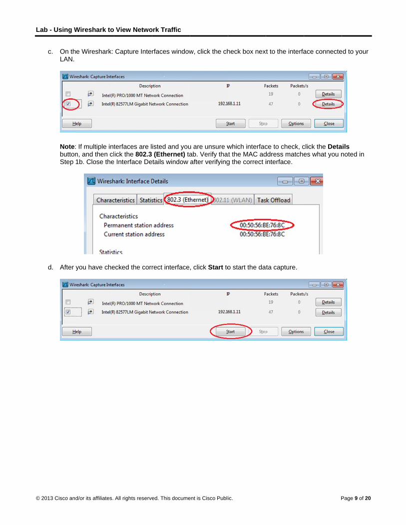
c. On thLAN.
Note:buttonStep
d. After y
Wireshark to
d/or its affiliates.
e Wireshark:
If multiple intn, and then cl1b. Close the
you have che
View Netwo
All rights reserve
Capture Inte
terfaces are lick the 802.3
e Interface De
ecked the corr
ork Traffic
ed. This docume
rfaces window
isted and you (Ethernet) ta
etails window
rect interface
ent is Cisco Publi
w, click the ch
u are unsure wab. Verify thaafter verifying
, click Start to
ic.
heck box nex
which interfacat the MAC adg the correct i
o start the da
xt to the interfa
ce to check, cddress matcheinterface.
ta capture.
P
ace connecte
click the Detaes what you n
Page 9 of 20
ed to your
ails noted in

L
©
Lab - Using W
© 2013 Cisco and
Informcolors
e. This iyour Pcaptuthe Fi(ping)
Wireshark to
d/or its affiliates.
mation will stas based on pr
nformation caPC and the LAred by Wireshlter box at the) PDUs.
View Netwo
All rights reserve
art scrolling dorotocol.
an scroll by veAN. We can ahark. For thise top of Wires
ork Traffic
ed. This docume
own the top s
ery quickly deapply a filter t lab, we are oshark and pre
ent is Cisco Publi
ection in Wire
epending on wto make it easonly interestedess Enter or c
ic.
eshark. The d
what communsier to view and in displayin
click on the Ap
data lines will
nication is taknd work with
ng ICMP (pingpply button to
Pa
appear in diff
king place betthe data that
g) PDUs. Typeo view only IC
age 10 of 20
fferent
tween is being e icmp in CMP

L
©
Lab - Using W
© 2013 Cisco and
f. This finterfareceivWires
Note:blockion ho
g. Stop c
Wireshark to
d/or its affiliates.
filter causes aace. Bring up ved from yourshark again.
If your team ing these req
ow to allow IC
capturing dat
View Netwo
All rights reserve
all data in the the comman
r team membe
member’s PCuests. PleaseMP traffic thro
a by clicking t
ork Traffic
ed. This docume
top window tod prompt winer. Notice tha
C does not ree see Appendough the firew
the Stop Cap
ent is Cisco Publi
o disappear, dow that you
at you start se
eply to your pidix A: Allowingwall using Win
pture icon.
ic.
but you are sopened earli
eeing data ap
ngs, this mayg ICMP Traffindows 7.
still capturing ier and ping thpear in the to
y be because c Through a F
Pa
the traffic on he IP address
op window of
their PC firewFirewall for in
age 11 of 20
the s that you
wall is nformation
L
©
S
Lab - Using W
© 2013 Cisco and
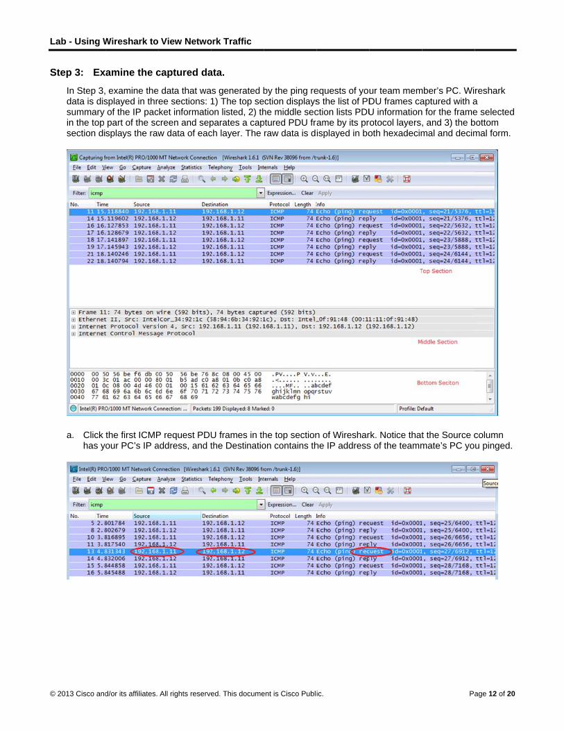
Step 3: Ex
In Step 3,data is dissummary in the top section di
a. Click has y
Wireshark to
d/or its affiliates.
amine the c
examine thesplayed in throf the IP pacpart of the scsplays the raw
the first ICMPour PC’s IP a
View Netwo
All rights reserve
captured da
e data that waee sections: 1
cket informatiocreen and sepw data of eac
P request PDUaddress, and t
ork Traffic
ed. This docume
ata.
as generated b1) The top seon listed, 2) thparates a capch layer. The
U frames in ththe Destinatio
ent is Cisco Publi
by the ping reection displayshe middle secptured PDU fraraw data is d
he top sectionon contains th
ic.
equests of yous the list of PDction lists PDUame by its prisplayed in bo
n of Wiresharhe IP address
ur team memDU frames caU informationrotocol layers,oth hexadecim
rk. Notice thats of the teamm
Pa
mber’s PC. Wiaptured with an for the frame, and 3) the bmal and decim
t the Source cmate’s PC yo
age 12 of 20
reshark a e selected bottom mal form.
column u pinged.

L
©
P
S
Lab - Using W
© 2013 Cisco and
b. With tthe le
Does
Does
How i
Note:packefor tra
Part 3: CIn Part 3, pings. Yo
Step 1: Sta
a. Click
Wireshark to
d/or its affiliates.
this PDU framft of the Ethe
the Source M
the Destinati
s the MAC ad
In the precedet PDU (IPv4 ansmission on
Capture ayou will ping u will then de
art capturin
the Interface
View Netwo
All rights reserve
me still selecternet II row to
MAC address
on MAC addr
ddress of the
ding exampleheader) whic
n the LAN.
and Analyremote hoststermine what
g data on in
e List icon to
ork Traffic
ed. This docume
ed in the top sview the Des
match your P
ress in Wiresh
pinged PC o
e of a capturedch is then enc
yze Remos (hosts not ot is different a
nterface.
bring up the l
ent is Cisco Publi
section, navigstination and S
PC’s interface
hark match th
btained by yo
d ICMP requecapsulated in a
ote ICMP n the LAN) an
about this data
ist PC interfa
ic.
gate to the miSource MAC
e?
he MAC addre
our PC?
est, ICMP datan Ethernet I
Data in Wnd examine tha from the da
aces again.
iddle section. addresses.
ess that of yo
ta is encapsuI frame PDU
Wiresharkhe generatedta examined
Pa
Click the plu
our team mem
ulated inside a(Ethernet II h
k d data from thin Part 2.
age 13 of 20
s sign to
mber’s?
an IPv4 header)
ose

L
©
Lab - Using W
© 2013 Cisco and
b. Make
c. A winneces
Wireshark to
d/or its affiliates.
sure the che
dow promptsssary to save
View Netwo
All rights reserve
eck box next to
to save the pthis data. Clic
ork Traffic
ed. This docume
o the LAN int
previously capck Continue
ent is Cisco Publi
terface is chec
ptured data bwithout Sav
ic.
cked, and the
before startingving.
en click Start
g another cap
Pa
.
pture. It is not
age 14 of 20

L
©
S
Lab - Using W
© 2013 Cisco and
d. With t
1) w
2) w
3) w
Note:an IP
e. You c
Step 2: Ex
a. Revieyou p
1st Lo
2nd
Lo
3rd
Lo
Wireshark to
d/or its affiliates.
the capture a
www.yahoo.co
www.cisco.com
www.google.co
When you paddress. Not
can stop captu
amining an
ew the captureinged. List th
cation: IP
ocation: IP
ocation: IP
View Netwo
All rights reserve
ctive, ping the
om
m
om
ing the URLste the IP addr
uring data by
d analyzing
ed data in Wie destination
:
:
:
ork Traffic
ed. This docume
e following th
listed, noticeress received
clicking the S
g the data fr
reshark, examIP and MAC
ent is Cisco Publi
ree website U
e that the Dom for each URL
Stop Capture
rom the rem
mine the IP anaddresses fo
MAC:
MAC:
MAC:
ic.
URLs:
main Name SeL.
e icon.
mote hosts.
nd MAC addror all three loc
erver (DNS) t
resses of the cations in the
Pa
translates the
three locationspace provid
age 15 of 20
e URL to
ns that ded.

L
©
R
A
S
Lab - Using W
© 2013 Cisco and
b. What
c. How d
Reflection Why doesremote ho
Appendix AIf the memappendix the new IC
Step 1: Cre
a. From
b. From
Wireshark to
d/or its affiliates.
is significant
does this info
s Wireshark sosts?
A: Allowingmbers of yourdescribes hoCMP rule afte
eate a new
the Control P
the System a
View Netwo
All rights reserve
about this inf
rmation differ
how the actu
g ICMP Trar team are unaow to create aer you have co
inbound ru
Panel, click th
and Security w
ork Traffic
ed. This docume
formation?
r from the loca
al MAC addre
affic Throuable to ping y rule in the firompleted the
le allowing
e System an
window, click
ent is Cisco Publi
al ping inform
ess of the loc
ugh a Firewyour PC, the frewall to allowlab.
ICMP traffi
nd Security o
Windows Fi
ic.
mation you rec
cal hosts, but
wall firewall may bw ping reques
c through t
option.
irewall.
ceived in Part
not the actua
be blocking thsts. It also des
the firewall.
Pa
t 2?
al MAC addres
hose requestsscribes how t
age 16 of 20
ss for the
s. This o disable

L
©
Lab - Using W
© 2013 Cisco and
c. In the
d. On thNew R
Wireshark to
d/or its affiliates.
e left pane of t
e Advanced SRule… on the
View Netwo
All rights reserve
the Windows
Security winde right sideba
ork Traffic
ed. This docume
Firewall wind
ow, choose tar.
ent is Cisco Publi
dow, click Adv
he Inbound R
ic.
vanced setti
Rules option
ngs.
on the left sid
Pa
debar and the
age 17 of 20
en click
L
©
Lab - Using W
© 2013 Cisco and
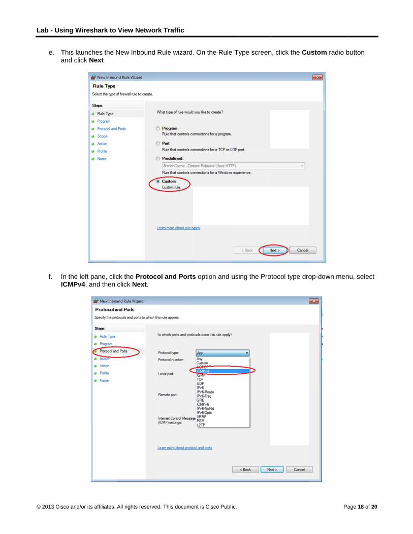
e. This land c
f. In theICMP
Wireshark to
d/or its affiliates.
aunches the click Next
e left pane, cliPv4, and then
View Netwo
All rights reserve
New Inbound
ck the Protocclick Next.
ork Traffic
ed. This docume
d Rule wizard
col and Ports
ent is Cisco Publi
. On the Rule
s option and u
ic.
e Type screen
using the Pro
n, click the Cu
otocol type dro
Pa
ustom radio b
op-down men
age 18 of 20
button
nu, select
L
©
S
Lab - Using W
© 2013 Cisco and
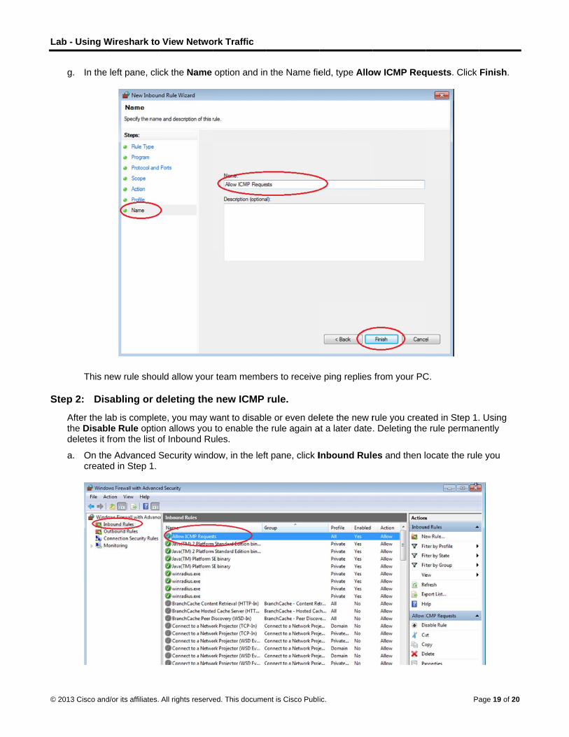
g. In the
This n
Step 2: Dis
After the lthe Disabdeletes it
a. On thcreate
Wireshark to
d/or its affiliates.
e left pane, cli
new rule shou
sabling or d
ab is completble Rule optiofrom the list o
e Advanced Sed in Step 1.
View Netwo
All rights reserve
ck the Name
uld allow your
deleting the
te, you may won allows you of Inbound Ru
Security wind
ork Traffic
ed. This docume
option and in
r team membe
new ICMP
want to disablto enable the
ules.
ow, in the left
ent is Cisco Publi
n the Name fie
ers to receive
rule.
e or even dele rule again a
t pane, click I
ic.
eld, type Allo
e ping replies
lete the new rat a later date
Inbound Rule
ow ICMP Req
from your PC
rule you creat. Deleting the
es and then l
Pa
quests. Click
C.
ted in Step 1.e rule perman
ocate the rule
age 19 of 20
Finish.
. Using ently
e you

L
©
Lab - Using W
© 2013 Cisco and
b. To dischangstatus
c. To peagain
Wireshark to
d/or its affiliates.
sable the rulege to Enable s of the rule a
ermanently de to allow ICM
View Netwo
All rights reserve
e, click the DisRule. You ca
also shows in
elete the ICMPP replies.
ork Traffic
ed. This docume
sable Rule opan toggle backthe Enabled
P rule, click D
ent is Cisco Publi
ption. When yk and forth becolumn of the
Delete. If you
ic.
you choose thetween Disabe Inbound Ru
choose this o
his option, yoble Rule and Eles list.
option, you m
Pa
u will see thisEnable Rule;
ust re-create
age 20 of 20
s option the
the rule