lab on a chip - | boston...
TRANSCRIPT

Cite this: Lab Chip, 2013, 13, 3246
Microfluidics embedded within extracellular matrix todefine vascular architectures and pattern diffusivegradients
Received 18th April 2013,Accepted 7th June 2013
DOI: 10.1039/c3lc50493j
www.rsc.org/loc
Brendon M. Baker, Britta Trappmann, Sarah C. Stapleton, Esteban Toroand Christopher S. Chen*
Gradients of diffusive molecules within 3D extracellular matrix (ECM) are essential in guiding many
processes such as development, angiogenesis, and cancer. The spatial distribution of factors that guide
these processes is complex, dictated by the distribution and architecture of vasculature and presence of
surrounding cells, which can serve as sources or sinks of factors. To generate temporally and spatially
defined soluble gradients within a 3D cell culture environment, we developed an approach to patterning
microfluidically ported microchannels that pass through a 3D ECM. Micromolded networks of sacrificial
conduits ensconced within an ECM gel precursor solution are dissolved following ECM gelation to yield
functional microfluidic channels. The dimensions and spatial layout of channels are readily dictated using
photolithographic methods, and channels are connected to external flow via a gasket that also serves to
house the 3D ECM. We demonstrated sustained spatial patterning of diffusive gradients dependent on the
architecture of the microfluidic network, as well as the ability to independently populate cells in either the
channels or surrounding ECM, enabling the study of 3D morphogenetic processes. To highlight the utility
of this approach, we generated model vascular networks by lining the channels with endothelial cells and
examined how channel architecture, through its effects on diffusion patterns, can guide the location and
morphology of endothelial sprouting from the channels. We show that locations of strongest gradients
define positions of angiogenic sprouting, suggesting a mechanism by which angiogenesis is regulated in
vivo and a potential means to spatially defining vasculature in tissue engineering applications. This flexible
3D microfluidic approach should have utility in modeling simple tissues and will aid in the screening and
identification of soluble factor conditions that drive morphogenetic events such as angiogenesis.
Introduction
In addition to serving as a physical support for cells, theextracellular matrix (ECM) plays an integral role in regulatingthe distribution of nutrients, gases such as oxygen and nitricoxide, and soluble effectors including morphogens, growthfactors, hormones, and cytokines. Gradients of such moleculesare essential in regulating numerous fundamental biologicalprocesses: progenitor cell differentiation and tissue patterningduring development,1,2 angiogenesis that accompanies tissuerepair in the adult,3,4 and tumor cell invasion and homingresponsible for metastatic disease.5 In all of these processes,the spatial presentation of diffusible factors in tissues iscomplex, largely dictated by the distribution and morphologyof vascular structures, as well as the structure and porosity of
the surrounding ECM and the density and metabolic activity ofsurrounding cells.6
Studying these intricate processes and their dependencieson diffusible gradients in vitro is significantly aided bymicrofluidic approaches, which enable a high degree ofcontrol over the timing and spatial presentation of biologicalfactors.7–9 Numerous devices exist to elegantly and preciselycontrol the soluble factors overlying cells plated on 2Dsurfaces,10,11 however fewer systems exist for defining solublefactor presentation to single cells or multicellular structuresfully embedded within a 3D matrix. It is now well establishedthat native cell–cell and cell–ECM interactions can be betterrecapitulated in 3D culture settings.12 Indeed, the higher ordermorphogenetic events described above are impossible tocapture on 2D surfaces, as these processes require cells toinvade, remodel, or otherwise reconfigure the 3D scaffold. Assuch, microfluidic devices have been developed for applying agradient to cells embedded within ECM.13–15 As gradients ofsoluble factors are heavily implicated in angiogenesis, recentefforts have focused on exposing endothelial structures to
Tissue Microfabrication Lab, Department of Bioengineering, University of
Pennsylvania, Philadelphia, PA 19104, USA. E-mail: [email protected];
http://www.seas.upenn.edu/~chenlab/index.html; Fax: +1 215 746-1752; Tel: +1 215
746-1754
Lab on a Chip
PAPER
3246 | Lab Chip, 2013, 13, 3246–3252 This journal is � The Royal Society of Chemistry 2013
Publ
ishe
d on
13
June
201
3. D
ownl
oade
d by
Uni
vers
ity o
f Pe
nnsy
lvan
ia L
ibra
ries
on
27/0
9/20
13 2
1:32
:10.
View Article OnlineView Journal | View Issue
gradients of angiogenic factors.16–19 However, many of theseprevious approaches place microfluidic channels at the outeredge of the ECM, thereby limiting gradients to relativelysimple fields and constraining the shape and path ofendothelialized vessels and subsequent direction of invasion.Others that have placed fluidic channels within the ECM itselfhave limited their studies to rectilinear channel patterns.13,20
Thus, the ability to generate more complex network architec-tures and study their effects on endothelial cells has not yetbeen explored. Here we generate complex diffusion patterns ofsoluble factors during long-term morphogenetic processes byshaping the vasculature that pervades the surrounding 3DECM.
To generate temporally and spatially defined solublegradients with more complex geometries, we developed anapproach to patterning ported microchannels within a 3DECM. Lithographically-defined sacrificial channel structureswere micromolded in gelatin on top of a glass slide, ensconcedwithin a collagen gel precursor solution, and subsequentlydissolved following collagen gelation to yield a microfluidicnetwork embedded within 3D ECM. These microfluidicchannels were connected to controlled external flow or mediareservoirs via a gasket which also served to house the 3D ECM.Individual cell populations were encapsulated within the gelprecursor or seeded inside the resulting channels to definestromal and endothelial cell populations, respectively. Bydefining channel geometries, diffusive gradients were spatiallypatterned, enabling the study of biological processes thatoccur in a 3D setting under the guidance of complex gradientsof soluble factors, such as endothelial sprouting duringangiogenesis. We used this approach to examine how thegeometry of endothelial vasculature alters the spatial pattern-ing of diffusive gradients and in turn influences the resultinginvasion of endothelial cells during angiogenic sprouting.
Experimental
Device fabrication
Gelatin channel templates and gaskets were fabricated bycasting poly(dimethylsiloxane) (PDMS; Sylgard 184; Dow-Corning) off silicon wafer masters possessing SU-8 photoresiststructures (Microchem) generated by standard photolithogra-phy. Masks were designed in Adobe Illustrator and areprovided in the supplementary information. Following curing,PDMS gaskets were removed from the master and ports orreservoirs were cut with biopsy punches of varying diameters.Gaskets and glass slides were exposed to oxygen plasma torender surfaces hydrophilic and immediately treated withsequential 2 h incubations in 0.1 mg ml21 poly-L-lysine(Sigma) and 5% v/v glutaraldehyde (Sigma) to crosslink theeventual collagen gel to the gasket walls. Following surfacetreatment, PDMS templates defining the gelatin channel wereapplied to the glass slide and a warmed 10% w/v gelatinsolution (from porcine skin, Sigma) was drawn through thechannel template and allowed to solidify prior to removal ofthe stamp. Separation of the PDMS stamp from the glass slide
frequently occurred when introducing gelatin via positivepressure, but manually applied suction could achieve the sameresult without separation occurring. The surface-treated gasketwas then registered upon the gelatin channel structure and asolution of rat tail collagen I (BD Biosciences, prepared as in21)was pipetted into the central chamber and allowed to gel at RTfor 30 min. The assembled device was then incubated at 37 uCto melt the gelatin structure, thereby leaving open channels inthe persisting collagen gel.
Device validation
To confirm that channels were open and free of leaks, 3 mmfluorescein polystyrene microspheres (Polysciences) wereintroduced into the reservoirs and the flow of microspheresdue to hydrostatic pressure was examined by epifluorescence.In order to characterize the formation and stability of diffusivegradients, 200 mm thick devices were fabricated with a 6 mgml21 collagen gel containing a single branched channelinitiating from two open media reservoirs and a single outletport (Fig. 1D). Reservoirs were filled with 250 mg ml21
solutions of 110 kDa fluorescein-conjugated dextran (Sigma)and PBS. A syringe pump was connected to the outlet and fluidwas withdrawn at 20 ml h21. The resulting diffusion offluorescent dextran within the central portion of the devicewas imaged once every 10 min for 12 h on a Nikon Ti Eclipseepifluorescent microscope. Fluorescence intensity across thedevice was quantified with FIJI.
Cell culture
For endothelial sprouting studies, devices were generated with500 mm-thick 3 mg ml21 collagen gels containing twoindependent channels terminating in open media reservoirs(Fig. 1C). HUVECs were purchased from a commercial source(Lonza) and expanded to passage 6–8 in EGM-2 (Lonza) priorto use. One of the two channels was endothelialized withHUVECs by pipetting a concentrated cell suspension (5 6 106
cells ml21) into reservoirs and carefully inverting the deviceonto parafilm, in order to seed the top and sides of thechannel. Following an hour long static incubation at 37 uC toallow for HUVEC adhesion to the channel walls, all reservoirswere filled with EGM-2 and the devices were placed on aplatform rocker (BenchRocker, BR2000) at 0.1 Hz overnight.The following day, the reservoirs of the endothelializedchannel were replenished with EGM-2 and the reservoirs ofthe acellular channel were replenished with EGM-2 supple-mented with 50 ng ml21 vascular endothelial growth factor(VEGF, R&D), 50 ng ml21 basic fibroblast growth factor (bFGF,R&D) and 50 ng ml21 phorbol myristate acetate (PMA, Sigma)to facilitate HUVEC sprouting as described in ref. 17. Inadditional studies, NIH 3T3s were expanded to passage 10,trypsinized, and resuspended in the collagen gel precursorsolution prior to injection into the device.
Sprout imaging
To image sprout structures, devices following six days ofculture were fixed in 4% v/v paraformaldehyde and stainedwith phalloidin-Alexa488 (Life Technologies) and DAPI (Sigma)for filamentous actin and nuclei, respectively. In additionalstudies, separate populations of HUVECs were fluorescently
This journal is � The Royal Society of Chemistry 2013 Lab Chip, 2013, 13, 3246–3252 | 3247
Lab on a Chip Paper
Publ
ishe
d on
13
June
201
3. D
ownl
oade
d by
Uni
vers
ity o
f Pe
nnsy
lvan
ia L
ibra
ries
on
27/0
9/20
13 2
1:32
:10.
View Article Online
labeled with cell trackers CMPTX and CMFDA following themanufacturer’s instructions (Life Technologies) prior toseeding into devices. Confocal images were acquired with aZeiss LSM 710 system and lower magnification images wereacquired on a Nikon TE200 epifluorescence microscope.Maximum projections were generated using Zen software(Zeiss). For sprouting quantification, 46 images of multipleDAPI-stained devices (n = 4) were thresholded, co-registered,and averaged to generate heat maps using custom Matlabscripts.
Modeling
The COMSOL Multiphysics suite (version 4.2) was used tomodel steady state diffusion patterns as a function of channelgeometry. Initially, 3D models were generated to examinedepth dependencies and to confirm that 2D simplificationscould faithfully capture the 3D phenomenon. Subsequently,
2D models were generated by importing device geometriesdirectly from lithographic masks created in Adobe Illustrator.Model parameters including the permeability (5.5 6 10214 m2)and porosity (99.6%) of the surrounding collagenous matrix,diffusivity (1 6 1029 m2 s21) of the solute, and flow rateswithin the channels (10 nl s21) were defined.22,23 Predictedsteady state diffusive patterns are presented.
Results and discussion
Device design and rationale
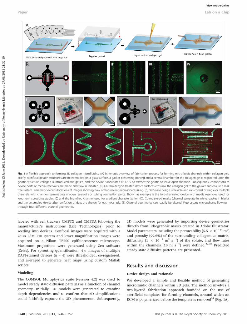
We developed a simple and flexible method of generatingmicrofluidic channels within 3D gels. The method involves atwo-layered fabrication approach founded on the use ofsacrificial templates for forming channels, around which anECM is polymerized before the template is removed24 (Fig. 1A).
Fig. 1 A flexible approach to forming 3D collagen microfluidics. (A) Schematic overview of fabrication process for forming microfluidic channels within collagen gels.Briefly, sacrificial gelatin structures are micromolded on a glass surface, a gasket possessing porting and a central chamber for the collagen gel is registered upon thegelatin structure, collagen is introduced and gelled, and the device is incubated at 37 uC to extract the gelatin to leave open channels. Subsequently, connections todevice ports or media reservoirs are made and flow is initiated. (B) Glutaraldehyde treated device surfaces crosslink the collagen gel to the gasket and ensure a leakfree system. Schematic depicts locations of images showing flow of fluorescent microspheres (i–iv). (C, D) Device design is flexible and can consist of single or multiplechannels, with channels terminating in open reservoirs or tubing connection ports. Shown as example is the two-channeled device with media reservoirs used forlong-term sprouting studies (C) and the branched channel used for gradient characterization (D). Co-registered masks (channel template in white, gasket in black),and the assembled device after perfusion of dyes are shown for each example. (E) Channel geometries can readily be altered. Fluorescent microspheres flowingthrough four different channel geometries.
3248 | Lab Chip, 2013, 13, 3246–3252 This journal is � The Royal Society of Chemistry 2013
Paper Lab on a Chip
Publ
ishe
d on
13
June
201
3. D
ownl
oade
d by
Uni
vers
ity o
f Pe
nnsy
lvan
ia L
ibra
ries
on
27/0
9/20
13 2
1:32
:10.
View Article Online

We illustrate this approach using gelatin as the sacrificialmaterial and purified type I collagen gels as the ECM. Collagenmatrices are commonly used for studying numerous 3Dcellular processes,25 and gelatin was selected due to itsgelation dynamics which inversely complement the ther-mally-induced precipitation of collagen gels. Gelatin is firstdrawn into PDMS microfluidic channels placed upon a glasssurface, gelled, and the PDMS channels are removed. A gasketpossessing a central chamber to house the eventual ECM isthen registered upon the gelatin structures and collagen isinjected into the chamber and gelled. The micromoldedgelatin structures are then melted, thereby leaving functionalchannels behind. Subsequently, connections are made to thedevice ports on the gasket, mediating mechanically stableconnections between external fluid sources and the delicategel. The internal walls of the devices are surface-treated withglutaraldehyde to covalently bind the collagen gel to thegasket, ensuring a leak free system as demonstrated by thecontrolled flow of fluorescent microspheres through the device(Fig. 1B). To illustrate the broad utility and flexibility of thisapproach, devices were fabricated with multiple independentchannels terminating in open reservoirs suitable for long-termculture studies (Fig. 1C) or a single branched channel withported outlets for connection to external pumps (Fig. 1D) witha variety of different channel geometries and sizes (Fig. 1E).Given the simplicity of the process, this approach is well suitedfor creating devices with application-specific channel archi-tectures and porting. Furthermore, although purified collagenwas used in developing this system, any ECM could be usedwith this approach.
Production and prediction of controlled and sustainedgradients in 3D gels
We used the device possessing a branched channel and singleoutlet (Fig. 1D) to demonstrate the ability to generate spatiallycontrolled, sustained gradients within 3D ECMs. Previouswork established this design as a means by which lowresolution syringe pumps can be used to generate balancedfluid flow in two channels, resulting in a diffusive gradientwithin the gel spanning the two channels.14 However, incontrast to numerous previous devices in which the channelswere defined by PDMS, our fluidic channels exist within thematrix itself. To visualize gradients, one reservoir was filledwith PBS containing fluorescent dextran and the other wasfilled with PBS, fluid was withdrawn from the device at aconstant flow rate, and time-lapse imaging was performed asthe diffusive gradient established over the course of 12 h(Fig. 2A). The point of convergence between the two channelsrevealed balanced, laminar flow (Fig. 2B). Shifting of thisinterface up or down would provide an indirect but convenientmeans of detecting mismatched channel flow rates that woulddrive convective flow across the ECM between the twochannels and therefore disrupt a diffusive gradient.Fluorescence intensity quantified across the central portionof the device demonstrated the gradient’s profile and time toequilibration (Fig. 2C).
As with native tissues, solute diffusion kinetics andresulting diffusion patterns within these fluidic devicesdepend on the channel architecture, characteristics of the
solute, and porosity of the ECM. To guide the design ofchannel architectures that would yield specific diffusionpatterns, we used a modeling approach to predict steadystate diffusion patterns. Device geometries were importedinto the COMSOL Multiphysics platform and parametersincluding the porosity and pore size of the surrounding gel,the size of the solute, and the flow rates within each channelwere defined to mimic our experimental setup. We foundgood agreement between experimental and theoretical gra-dients resulting from parallel and converging channels(Fig. 3A and B), suggesting that the computational approachwas indeed predictive and valid. Modeling the fully 3Ddistribution of diffusive factors in parallel channel devicesranging in height between 400 and 1200 mm thicknessrevealed that gradients persisted throughout the depth ofthe gel, even at a ratio of 1 : 6 between the channel heightand ECM thickness (Fig. 3C). Modeling of more intricatechannel geometries at different flow rates revealed thepotential for generating complex diffusion patterns(Fig. 3D). To prevent convective flow, symmetry was main-
Fig. 2 Formation of controlled and sustained gradients in 3D. (A) Schematicdepicting experimental setup and regions of images in panels B–C. (B) Point ofconvergence of branched channel demonstrating balanced, laminar flow of PBSwith (top channel) and without (bottom channel) fluorescent dextran. (C) Time-lapse imaging of the central portion of the device was performed. Shown areimages from six time points taken from the series. Note that the exposureduration was dramatically reduced relative to B to avoid intensity saturation. (D)Intensity plots (taken along the red line in C) demonstrating the profile and timeto equilibration of the diffusive gradient.
This journal is � The Royal Society of Chemistry 2013 Lab Chip, 2013, 13, 3246–3252 | 3249
Lab on a Chip Paper
Publ
ishe
d on
13
June
201
3. D
ownl
oade
d by
Uni
vers
ity o
f Pe
nnsy
lvan
ia L
ibra
ries
on
27/0
9/20
13 2
1:32
:10.
View Article Online

tained across the various source and sink channel architec-tures employed in this work. However, mismatching pathlengths can be designed to engineer points of controlledinterstitial pressure drops and resulting convective flow.
Engineering tissues for studying 3D morphogenetic processes
A major application for this fluidic platform is as a means formodeling simple tissues possessing endothelialized vesselssurrounded by a stromal space (Fig. 4A). To illustrate thepotential to incorporate various cellular components, deviceswere formed with 3T3 fibroblasts suspended in the collagensolution (modeling interstitial cells and space) and subse-quently seeded with HUVECs in the channels (modeling thevascular endothelium) (Fig. 4B). With culture, the endothelialcells proliferated and formed a confluent monolayer withinthe channels (Fig. 4C), consistent with previous reports.26
Given that angiogenesis is known to be driven by gradients of avariety of soluble effectors,4 we sought to examine howchannel geometry and resulting diffusion patterns of growthfactors (GF) influence endothelial invasion and sprouting.Endothelialized channels with different geometries werefabricated and gradients of soluble angiogenic GFs wereformed in long-term culture. After six days, 3D cellularinvasion into the surrounding ECM was evident as determinedby DAPI stained devices (Fig. 5A). Invasion occurred uniformlyalong the channel in devices with parallel channels, incontrast to devices with non-parallel channels where locationsof focused invasion coincided with points where the GFgradient was steepest. The ability to pattern soluble gradientsand thereby define locations of angiogenic sprouting couldhave significant utility in tissue engineering applications, forexample in cases where vasculature is required only in preciselocations within a tissue construct. Furthermore, the specifica-tion of sprouting location through the architecture of thevasculature demonstrates a potential mechanism by whichangiogenesis is spatially regulated in vivo.
Although parallel channels provide a uniform gradientacross an ECM that can offer a means to study how cellfunction is regulated by a specific gradient, other channelgeometries offered by the flexibility of our approach allows oneto explore a well-defined range of gradients. Using such anapproach, we examined how the steepness of a GF gradientimpacts invasion depth and sprouting morphology. HUVEC-seeded devices were fabricated with converging channels
Fig. 3 Theoretical modeling can aid the design of temporally and spatiallycomplex diffusive patterns. (A) Comparison of experimental and theoreticalgradients resulting from two parallel channels shows good agreement. Phasecontrast (left) and heat map-converted fluorescent (center) images following 12h of flow of fluorescent dextran in comparison to steady state model predictions(right). (B) Comparison of experimental and theoretical gradients generatedfrom two converging channels. (C) Diffusive gradients persist through the depthof the device, largely independent of device thickness. Model predictions ofsteady state diffusion patterns in parallel channel devices of 400 and 1200 mmthickness. (D) Model predictions of steady-state diffusive patterns resulting fromdifferent channel geometries (top) and varying flow rates within the samechannel geometry (bottom).
Fig. 4 Straightforward incorporation of cellular components provides a meansfor fabricating simple microfluidic models of tissues. (A) Schematic of a modeltissue containing multiple endothelialized tubules (pink and green) traversing astromal compartment containing mesenchymal cells (blue). Dashed lineindicates the presence of a glass surface. (B) Confocal image of DAPI labeled3T3s (blue) and two populations of HUVECs labeled with Cell Tracker dyes (pinkand green) incorporated directly into the gel and seeded along the channels,respectively. (C) Following seeding, HUVECs spread and proliferate, resulting inconfluent monolayers within the open microfluidic channels.
3250 | Lab Chip, 2013, 13, 3246–3252 This journal is � The Royal Society of Chemistry 2013
Paper Lab on a Chip
Publ
ishe
d on
13
June
201
3. D
ownl
oade
d by
Uni
vers
ity o
f Pe
nnsy
lvan
ia L
ibra
ries
on
27/0
9/20
13 2
1:32
:10.
View Article Online

which subject cells to a 4-fold range of concentrationgradients, analogous to existing 2D devices.27 Fluorescentimages of multiple devices were co-registered to generate aheat map (Fig. 5B). Invasion depth quantified across theconverging channel device revealed a non-linear relationshipbetween invasion depth and the strength of the GF gradient(Fig. 5C). Furthermore, confocal imaging performed atdifferent positions along the length of the channel revealedthat the morphology of the invasive structures variedconsiderably (Fig. 5D). Invading endothelial cells undersharper GF gradients formed multicellular structures withhigh cell density that lacked organization. At lower gradients,single cells or clusters of several cells were observed to migrateinto the collagen gel, but stalk-like multicellular structureswere not observed. Finally, at intermediate GF gradients,multicellular, stalk-like structures were observed to sprout inthe direction of the gradient (Fig. 5Dii). Taken together, theseresults suggest the existence of optimal GF gradients thatpromote cohesive multicellular sprouting, and establish arapid means towards identifying such conditions.
Summary
In summary, a multilayered, sacrificial channel templateapproach was developed to form microfluidic channels withina collagen gel for studying 3D cellular processes mediated bydiffusive gradients. Following device validation, we showedthrough experimental and theoretical approaches how altering
channel geometries influences diffusion patterns which can inturn guide 3D morphogenetic processes such as endothelialsprouting. This generalizable 3D microfluidic approachadaptable to other sacrificial materials28 should have utilityin modeling simple tissues containing stromal and epithelialcompartments and can aid in the screening and identificationof soluble factor conditions that drive morphogenetic eventssuch as endothelial sprouting.
Acknowledgements
This work was supported in part from grants from the NationalInstitutes of Health (grant numbers EB00262, EB08396,HL73305, GM74048) and Center for Engineering Cells andRegeneration of the University of Pennsylvania. B.M.B.acknowledges financial support from a Ruth L. KirschsteinNational Research Service Award. S.C.S. is supported by R25CA101871-07 from the National Cancer Institute. E.T. is anHHMI fellow of the Life Sciences Research Foundation.
References
1 J. B. Gurdon and P. Y. Bourillot, Nature, 2001, 413, 797–803.2 H. L. Ashe and J. Briscoe, Development, 2006, 133, 385–394.3 R. H. Adams and K. Alitalo, Nat. Rev. Mol. Cell Biol., 2007, 8,
464–478.4 P. Carmeliet and R. K. Jain, Nature, 2011, 473, 298–307.
Fig. 5 Channel geometries and resulting diffusion patterns dictate the location and morphology of 3D endothelial sprouting. (A) 3D invasion of DAPI stained HUVECsfollowing 6 days of culture in the presence of a chemokine and GF gradient. In all devices, the chemokine and GF cocktail was supplemented to the acellular channel(bottom, outlined in dashed lines) while endothelialized channels (top) were maintained in basal media. Invasion depth and sprouting morphology was examinedwithin the converging channel device (rightmost in panel (A)), which generates a diffusion pattern subjecting cells to a range of GF gradients. (B) Images of multipleDAPI stained devices (n = 4) were co-registered to generate a heat map, overlaid upon the steady state diffusion pattern (green). (C) Invasion depth quantified acrossthe converging channel device over a range of GF gradients (n = 4 devices, error bars denote standard deviations). (D) Maximum projections from confocal z-stacks ofphalloidin (red) and DAPI (blue) stained HUVEC invasion at positions denoted in (A).
This journal is � The Royal Society of Chemistry 2013 Lab Chip, 2013, 13, 3246–3252 | 3251
Lab on a Chip Paper
Publ
ishe
d on
13
June
201
3. D
ownl
oade
d by
Uni
vers
ity o
f Pe
nnsy
lvan
ia L
ibra
ries
on
27/0
9/20
13 2
1:32
:10.
View Article Online
5 R. R. Kay, P. Langridge, D. Traynor and O. Hoeller, Nat. Rev.Mol. Cell Biol., 2008, 9, 455–463.
6 L. G. Griffith and M. A. Swartz, Nat. Rev. Mol. Cell Biol.,2006, 7, 211–224.
7 S. Kim, H. J. Kim and N. L. Jeon, Integr. Biol., 2010, 2,584–603.
8 S. Chung, R. Sudo, V. Vickerman, I. K. Zervantonakis andR. D. Kamm, Ann. Biomed. Eng., 2010, 38, 1164–1177.
9 B. J. Kim and M. Wu, Ann. Biomed. Eng., 2012, 40,1316–1327.
10 G. A. Cooksey, C. G. Sip and A. Folch, Lab Chip, 2009, 9,417–426.
11 R. Gomez-Sjoberg, A. A. Leyrat, D. M. Pirone, C. S. Chenand S. R. Quake, Anal. Chem., 2007, 79, 8557–8563.
12 B. M. Baker and C. S. Chen, J. Cell Sci., 2012, 125,3015–3024.
13 N. W. Choi, M. Cabodi, B. Held, J. P. Gleghorn, L.J. Bonassar and A. D. Stroock, Nat. Mater., 2007, 6, 908–915.
14 W. Saadi, S. W. Rhee, F. Lin, B. Vahidi, B. G. Chung and N.L. Jeon, Biomed. Microdevices, 2007, 9, 627–635.
15 U. Haessler, Y. Kalinin, M. A. Swartz and M. Wu, Biomed.Microdevices, 2009, 11, 827–835.
16 Y. Zheng, J. Chen, M. Craven, N. W. Choi, S. Totorica,A. Diaz-Santana, P. Kermani, B. Hempstead, C. Fischbach-Teschl, J. A. Lopez and A. D. Stroock, Proc. Natl. Acad. Sci.U. S. A., 2012, 109, 9342–9347.
17 V. Vickerman, J. Blundo, S. Chung and R. Kamm, Lab Chip,2008, 8, 1468–1477.
18 I. K. Zervantonakis, S. K. Hughes-Alford, J. L. Charest, J.S. Condeelis, F. B. Gertler and R. D. Kamm, Proc. Natl.Acad. Sci. U. S. A., 2012, 109, 13515–13520.
19 S. Kim, H. Lee, M. Chung and N. L. Jeon, Lab Chip, 2013,13, 1489–1500.
20 D.-H. T. Nguyen, S. C. Stapleton, M. T. Yang, S. S. Cha, C.K. Choi, P. A. Galie and C. S. Chen, Proc. Natl. Acad. Sci. U.S. A., 2013, 110, 6712–6717.
21 R. M. Kuntz and W. M. Saltzman, Biophys. J., 1997, 72,1472–1480.
22 P. A. Galie and J. P. Stegemann, Tissue Eng., Part C, 2011,17, 527–536.
23 S. Ramanujan, A. Pluen, T. D. McKee, E. B. Brown,Y. Boucher and R. K. Jain, Biophys. J., 2002, 83, 1650–1660.
24 A. P. Golden and J. Tien, Lab Chip, 2007, 7, 720.25 V. L. Cross, Y. Zheng, N. Won Choi, S. S. Verbridge, B.
A. Sutermaster, L. J. Bonassar, C. Fischbach and A.D. Stroock, Biomaterials, 2010, 31, 8596–8607.
26 K. M. Chrobak, D. R. Potter and J. Tien, Microvasc. Res.,2006, 71, 185–196.
27 J. Pihl, J. Sinclair, E. Sahlin, M. Karlsson, F. Petterson,J. Olofsson and O. Orwar, Anal. Chem., 2005, 77, 3897–3903.
28 J. S. Miller, K. R. Stevens, M. T. Yang, B. M. Baker, D.-H.T. Nguyen, D. M. Cohen, E. Toro, A. A. Chen, P. A. Galie,X. Yu, R. Chaturvedi, S. N. Bhatia and C. S. Chen, Nat.Mater., 2012, 11, 768–774.
3252 | Lab Chip, 2013, 13, 3246–3252 This journal is � The Royal Society of Chemistry 2013
Paper Lab on a Chip
Publ
ishe
d on
13
June
201
3. D
ownl
oade
d by
Uni
vers
ity o
f Pe
nnsy
lvan
ia L
ibra
ries
on
27/0
9/20
13 2
1:32
:10.
View Article Online