lab on a chip - national university of singapore · pdf filelab on a chip paper cite this: lab...
TRANSCRIPT
Lab on a Chip
PAPER
Lab ChipThis journal is © The Royal Society of Chemistry 2015
aDepartment of Electrical and Computer Engineering and Singapore Institute for
Neurotechnology (SINAPSE), National University of Singapore, Singapore 117576.
E-mail: [email protected] of Biomedical Engineering and Singapore Institute for
Neurotechnology (SINAPSE), National University of Singapore, 117575, Singapore
† Electronic supplementary information (ESI) available: 1) The fabricationprocess; 2) gradient profiles of both the accumulation method and dilutionmethod with a flow rate of 500 nl min−1 for inlet 1; 3) detailed process for cellculture and immobilization in the U-shaped main channel; 4) viability test ofPC-9 cancer cells in a gradient from 0% to 90% generated by the accumulationmethod. See DOI: 10.1039/c4lc01451k
Cite this: Lab Chip, 2015, 15, 1445
Received 11th December 2014,Accepted 5th January 2015
DOI: 10.1039/c4lc01451k
www.rsc.org/loc
A convection-driven long-range linear gradientgenerator with dynamic control†
Hao Wang,a Chia-Hung Chen,*b Zhuolin Xiang,a Ming Wangb and Chengkuo Lee*a
We developed a novel gradient generator to achieve long range and linear chemical gradients with a
dynamic control function. The length of the gradient can be on the centimetre scale. The gradient profile
can be tuned by changing the flow rates. The device can work in both high flow rate regimes with large
shear stress and low flow rate regimes with minimum shear stress. The drug screening function was
demonstrated by the viability test of PC-9 cancer cells.
Introduction
Nowadays, engineering various gradients has attracted exten-sive attention for biomedical applications because gradientsplay essential roles in many biological activities and regulatea number of cellular functions in vivo. Chemical gradientshave been shown to affect various cell behaviours, such asmigration, proliferation, and differentiation during develop-ment.1,2 Microfluidic devices offer the possibility of generat-ing complex and well defined gradient profiles.
One of the most popular methods for generating chemicalgradients is to leverage the Christmas tree design.3–20 Twoor more fluids are mixed in different ratios by a channelnetwork, forming a gradient in the main channel by laminarflow. Because of the laminar regime that is inherent to fluidflow in microchannels, the geometry of the microdevice andthe flow rates can be tuned to subject the cultured cells towell-defined, diffusion-independent concentration profiles.However, existing microfluidic gradient generators encounterhydrodynamic shear stresses that arise from the smallcharacteristic dimensions of microfluidic channels. For mostcultured cells, the maintenance of low levels of hydrodynamicshear is vital for the preservation of their integrity. Toensure a good laminar flow and gradient profile in the main
channel, the fluid that flows out from each small channelshould have a symmetric flow rate pattern and differentmixing ratios of two kinds of fluids.4–17 A symmetric flow ratepattern could be realized by a symmetric channel network.But this symmetric channel network will induce a non-lineargradient profile. It is very challenging to optimize the chan-nel network which could realize both laminar flow and lineargradient profiles. Moreover, since the gradient generated bythe laminar flow is not affected by the flow rate, Christmastree designs also lack the function of dynamic control ofthe gradient profile. The initial fluid concentration from theinlet has to be changed if a different gradient profile needsto be studied. Since the laminar flow can only be maintainedat low Reynolds numbers, the length of the gradient is alsolimited.
Another major approach is to leverage the diffusion togenerate chemical gradients.21–34 The gradient generated bydiffusion is vulnerable to convection flow. Thus the mainissue with chemical gradient generators based on diffusion isthe isolation of convection flow during the gradient genera-tion procedure. For membrane-based diffusion chips,30–32,34
convection flows are physically isolated by thin membranesand only chemical molecules are allowed to diffuse throughthe membrane. For channel-based diffusion chips,28,33
convection flows are minimized by microchannels whosedimensions are much smaller than those of the main chan-nels to maintain chemical gradients. Due to the isolation ofconvection flow, the gradients are mainly maintained at alow or even static flow rate with a minimal level of shearstress which is ideal for cell culture. On the other hand, theduration required to stabilize the gradient is relatively longbecause of the low flow rate. Once the gradient is formed,it is not easy to have a dynamic control of the gradient pro-file. Moreover, the gradient profile is mainly determined bythe nature of diffusion; thus, linearity is not guaranteed. To
, 2015, 15, 1445–1450 | 1445
Lab on a ChipPaper
shorten the duration of stabilization of the gradient andenable an easier process for optimization and characteriza-tion, the length or area of the gradient is normally limited tothe hundreds of micrometer scale.
Method
Here we present a novel gradient generation method basedon convection-driven flow. This approach has many advan-tages over the methodologies developed so far since it cansimultaneously satisfy the following: (1) the length of thegradient can be on the centimetre scale and the time to stabi-lize the gradient is short. (2) A linear gradient profile can beobtained which cannot be realized by Christmas tree designsand diffusion based designs. Thus the concentration gradientprofiles can be relatively easily predicted. (3) The lineargradient profile can be tuned just by changing the flow ratewhich is not feasible in Christmas tree and diffusion baseddesigns. (4) The device can work in both high flow rateregimes with large shear stress and low flow rate regimeswith minimum shear stress.
Analysis and characterization
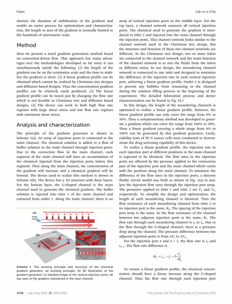
The principle of the gradient generator is shown inScheme 1(a). An array of injection ports is connected to themain channel. The chemical solution is added to a flow ofbuffer solution in the main channel through injection ports.Due to the convection flow in the main channel, eachsegment of the main channel will have an accumulation ofthe chemical injected from the injection ports before thissegment. Thus along the main channel, the concentration ofthe gradient will increase and a chemical gradient will beformed. The device used to realize this method is shown inScheme 1(b). The device has a 3D structure with three layers.For the bottom layer, the U-shaped channel is the mainchannel used to generate the chemical gradient. The buffersolution is injected into inlet 1 of the main channel andextracted from outlet 1. Along the main channel, there is an
1446 | Lab Chip, 2015, 15, 1445–1450
Scheme 1 The working principle and structure of the chemicalgradient generator; (a) working principle; (b) 3D illustration of thegradient generator; (c) detailed image of the vertical injection ports; (d)top view of the gradient maintained in the main channel.
array of vertical injection ports in the middle layer. For thetop layer, a channel network connects all vertical injectionports. The chemical used to generate the gradient is intro-duced to inlet 2 and injected into the main channel throughthe injection ports. This channel network looks similar to thechannel network used in the Christmas tree design. Butthe structure and function of these two channel networks aredifferent. In the Christmas tree design, two or more inletsare connected to the channel network and the main functionof the channel network is to mix the fluids from the inletsin different ratios. In our design, the meandering channelnetwork is connected to one inlet and designed to minimizethe difference of the injection rate in each vertical injectionport, achieving a linear gradient profile. Outlet 2 is designedto prevent any bubbles from remaining in the channelduring the solution filling process at the beginning of theexperiment. The detailed fabrication process and devicecharacterization can be found in Fig. S1.†
In this design, the length of the meandering channels isoptimized to realize a linear gradient profile. However, thelinear gradient profile can only cover the range from 0% to50%. Thus a complementary method was developed to gener-ate a gradient which can cover the range from 100% to 50%.Then a linear gradient covering a whole range from 0% to100% can be generated by this gradient generator. Lastly,viability tests of PC-9 cancer cells were conducted to demon-strate the drug screening capability of this device.
To realize a linear gradient profile, the injection rate ineach injection port at different positions in the main channelis expected to be identical. The flow rates in the injectionports are affected by the pressure applied to the connectionpart of the injection port and the main channel which varieswith the position along the main channel. To minimize thedifference of the flow rates in the injection ports, a discretefluidic circuit model was built as shown in Fig. 1(a) to ana-lyze the injection flow rates through the injection port array.The pressures applied to inlet 1 and inlet 2 are V1 and V2,respectively. To simplify the design and optimization, thelength of each meandering channel is identical. Thus theflow resistance of each meandering channel from inlet 2 toits injection port is the same, R0. The spacing of the injectionport array is the same. So the flow resistance of the channelbetween two adjacent injection ports is the same, R1. Theflow rate through each meandering channel is i1 to in. Due tothe flow through the U-shaped channel, there is a pressuredrop along the channel. The pressure difference between twoadjacent injection ports is from ΔV1 to ΔVn.
For the injection port n and n + 1, the flow rate is in andin+1. The flow rate difference is
i i i ViRn n nn 10
To ensure a linear gradient profile, the chemical concen-tration should have a linear increase along the U-shapedchannel. Thus the flow rate through each injection port
This journal is © The Royal Society of Chemistry 2015
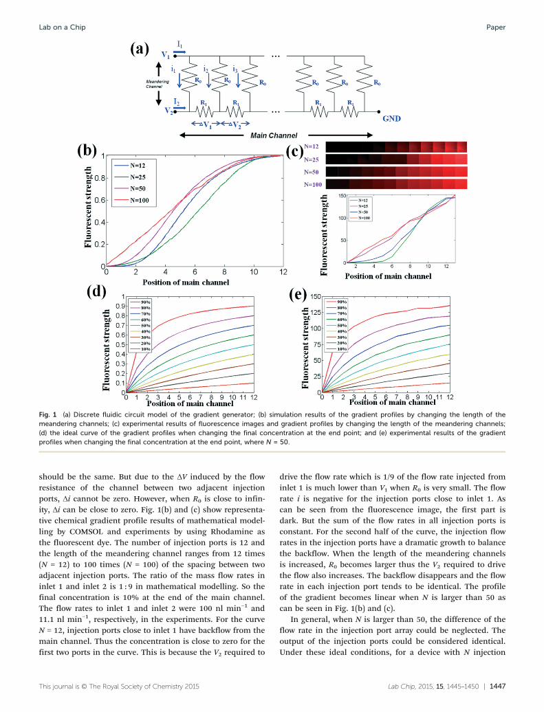
Fig. 1 (a) Discrete fluidic circuit model of the gradient generator; (b) simulation results of the gradient profiles by changing the length of themeandering channels; (c) experimental results of fluorescence images and gradient profiles by changing the length of the meandering channels;(d) the ideal curve of the gradient profiles when changing the final concentration at the end point; and (e) experimental results of the gradientprofiles when changing the final concentration at the end point, where N = 50.
Lab on a Chip Paper
should be the same. But due to the ΔV induced by the flowresistance of the channel between two adjacent injectionports, Δi cannot be zero. However, when R0 is close to infin-ity, Δi can be close to zero. Fig. 1(b) and (c) show representa-tive chemical gradient profile results of mathematical model-ling by COMSOL and experiments by using Rhodamine asthe fluorescent dye. The number of injection ports is 12 andthe length of the meandering channel ranges from 12 times(N = 12) to 100 times (N = 100) of the spacing between twoadjacent injection ports. The ratio of the mass flow rates ininlet 1 and inlet 2 is 1 : 9 in mathematical modelling. So thefinal concentration is 10% at the end of the main channel.The flow rates to inlet 1 and inlet 2 were 100 nl min−1 and11.1 nl min−1, respectively, in the experiments. For the curveN = 12, injection ports close to inlet 1 have backflow from themain channel. Thus the concentration is close to zero for thefirst two ports in the curve. This is because the V2 required to
This journal is © The Royal Society of Chemistry 2015
drive the flow rate which is 1/9 of the flow rate injected frominlet 1 is much lower than V1 when R0 is very small. The flowrate i is negative for the injection ports close to inlet 1. Ascan be seen from the fluorescence image, the first part isdark. But the sum of the flow rates in all injection ports isconstant. For the second half of the curve, the injection flowrates in the injection ports have a dramatic growth to balancethe backflow. When the length of the meandering channelsis increased, R0 becomes larger thus the V2 required to drivethe flow also increases. The backflow disappears and the flowrate in each injection port tends to be identical. The profileof the gradient becomes linear when N is larger than 50 ascan be seen in Fig. 1(b) and (c).
In general, when N is larger than 50, the difference of theflow rate in the injection port array could be neglected. Theoutput of the injection ports could be considered identical.Under these ideal conditions, for a device with N injection
Lab Chip, 2015, 15, 1445–1450 | 1447
Lab on a ChipPaper
ports, the chemical concentration of segment n of the mainchannel is
C
nNI
I nNI
n
2
1 2
(1)
When I is much smaller than I , then I portion in the
2 1 N 2denominator can be neglected, which is the situation in
Fig. 1(b) and (c) ( I I2 119
). The profile of the gradient should be
completely linear. But the linearity will deteriorate when I2increases. Fig. 1(d) shows the ideal curve of eqn (1) when thefinal concentration at the end of the channel ranges from10% to 90% by increasing I2. As can be seen in Fig. 1(d),when the final concentration is not higher than 50%, thelinearity is acceptable. The linearity increases with decreasingfinal concentration. Once the concentration is larger than
50%, meaning I2 is higher than I1, thenNI2 portion in the
denominator has a greater effect than I1. Thus the curve is notlinear anymore. Fig. 1(e) shows the corresponding experimen-tal results with the flow rate in inlet 1 equal to 100 nl min−1
and N = 50. For the results whose final concentration is nothigher than 50%, the curve is linear. Once the concentrationis higher than 50%, an obvious upper bending of the curve isobserved, making the curve not linear. Therefore, by using thismethod to achieve a linear concentration profile, the final con-centration cannot exceed 50%. But within the range from 0%to 50%, the linear gradient profile can have dynamic changesjust by changing the flow rate ratio of inlet 1 and inlet 2.
1448 | Lab Chip, 2015, 15, 1445–1450
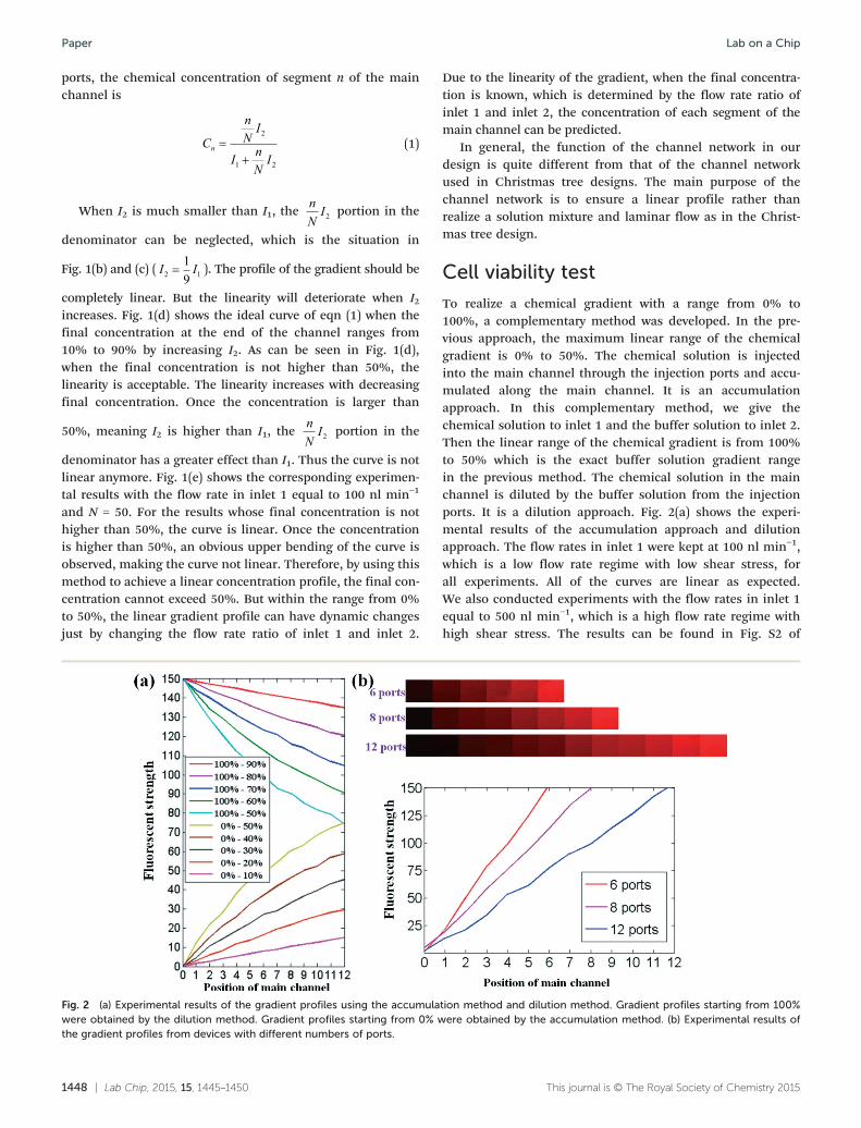
Fig. 2 (a) Experimental results of the gradient profiles using the accumulawere obtained by the dilution method. Gradient profiles starting from 0% wthe gradient profiles from devices with different numbers of ports.
Due to the linearity of the gradient, when the final concentra-tion is known, which is determined by the flow rate ratio ofinlet 1 and inlet 2, the concentration of each segment of themain channel can be predicted.
In general, the function of the channel network in ourdesign is quite different from that of the channel networkused in Christmas tree designs. The main purpose of thechannel network is to ensure a linear profile rather thanrealize a solution mixture and laminar flow as in the Christ-mas tree design.
Cell viability test
To realize a chemical gradient with a range from 0% to100%, a complementary method was developed. In the pre-vious approach, the maximum linear range of the chemicalgradient is 0% to 50%. The chemical solution is injectedinto the main channel through the injection ports and accu-mulated along the main channel. It is an accumulationapproach. In this complementary method, we give thechemical solution to inlet 1 and the buffer solution to inlet 2.Then the linear range of the chemical gradient is from 100%to 50% which is the exact buffer solution gradient rangein the previous method. The chemical solution in the mainchannel is diluted by the buffer solution from the injectionports. It is a dilution approach. Fig. 2(a) shows the experi-mental results of the accumulation approach and dilutionapproach. The flow rates in inlet 1 were kept at 100 nl min−1,which is a low flow rate regime with low shear stress, forall experiments. All of the curves are linear as expected.We also conducted experiments with the flow rates in inlet 1equal to 500 nl min−1, which is a high flow rate regime withhigh shear stress. The results can be found in Fig. S2 of
This journal is © The Royal Society of Chemistry 2015
tion method and dilution method. Gradient profiles starting from 100%ere obtained by the accumulation method. (b) Experimental results of
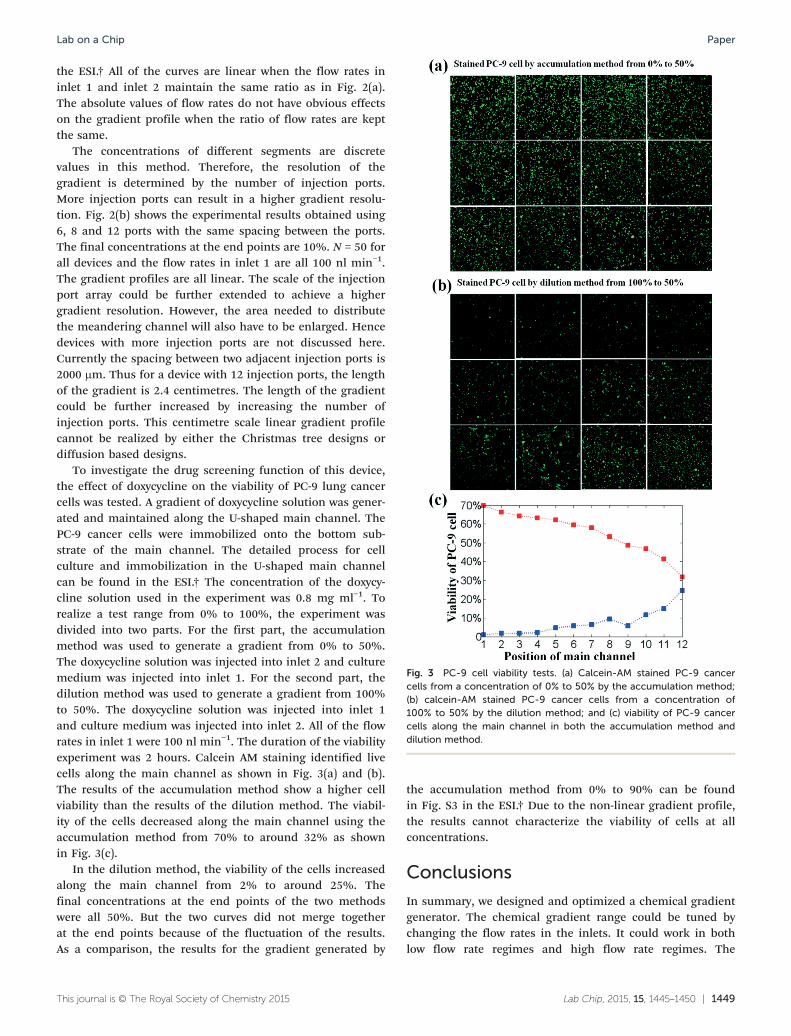
Fig. 3 PC-9 cell viability tests. (a) Calcein-AM stained PC-9 cancercells from a concentration of 0% to 50% by the accumulation method;(b) calcein-AM stained PC-9 cancer cells from a concentration of100% to 50% by the dilution method; and (c) viability of PC-9 cancercells along the main channel in both the accumulation method anddilution method.
Lab on a Chip Paper
the ESI.† All of the curves are linear when the flow rates ininlet 1 and inlet 2 maintain the same ratio as in Fig. 2(a).The absolute values of flow rates do not have obvious effectson the gradient profile when the ratio of flow rates are keptthe same.
The concentrations of different segments are discretevalues in this method. Therefore, the resolution of thegradient is determined by the number of injection ports.More injection ports can result in a higher gradient resolu-tion. Fig. 2(b) shows the experimental results obtained using6, 8 and 12 ports with the same spacing between the ports.The final concentrations at the end points are 10%. N = 50 forall devices and the flow rates in inlet 1 are all 100 nl min−1.The gradient profiles are all linear. The scale of the injectionport array could be further extended to achieve a highergradient resolution. However, the area needed to distributethe meandering channel will also have to be enlarged. Hencedevices with more injection ports are not discussed here.Currently the spacing between two adjacent injection ports is2000 μm. Thus for a device with 12 injection ports, the lengthof the gradient is 2.4 centimetres. The length of the gradientcould be further increased by increasing the number ofinjection ports. This centimetre scale linear gradient profilecannot be realized by either the Christmas tree designs ordiffusion based designs.
To investigate the drug screening function of this device,the effect of doxycycline on the viability of PC-9 lung cancercells was tested. A gradient of doxycycline solution was gener-ated and maintained along the U-shaped main channel. ThePC-9 cancer cells were immobilized onto the bottom sub-strate of the main channel. The detailed process for cellculture and immobilization in the U-shaped main channelcan be found in the ESI.† The concentration of the doxycy-cline solution used in the experiment was 0.8 mg ml−1. Torealize a test range from 0% to 100%, the experiment wasdivided into two parts. For the first part, the accumulationmethod was used to generate a gradient from 0% to 50%.The doxycycline solution was injected into inlet 2 and culturemedium was injected into inlet 1. For the second part, thedilution method was used to generate a gradient from 100%to 50%. The doxycycline solution was injected into inlet 1and culture medium was injected into inlet 2. All of the flowrates in inlet 1 were 100 nl min−1. The duration of the viabilityexperiment was 2 hours. Calcein AM staining identified livecells along the main channel as shown in Fig. 3(a) and (b).The results of the accumulation method show a higher cellviability than the results of the dilution method. The viabil-ity of the cells decreased along the main channel using theaccumulation method from 70% to around 32% as shownin Fig. 3(c).
In the dilution method, the viability of the cells increasedalong the main channel from 2% to around 25%. Thefinal concentrations at the end points of the two methodswere all 50%. But the two curves did not merge togetherat the end points because of the fluctuation of the results.As a comparison, the results for the gradient generated by
This journal is © The Royal Society of Chemistry 2015
the accumulation method from 0% to 90% can be foundin Fig. S3 in the ESI.† Due to the non-linear gradient profile,the results cannot characterize the viability of cells at allconcentrations.
Conclusions
In summary, we designed and optimized a chemical gradientgenerator. The chemical gradient range could be tuned bychanging the flow rates in the inlets. It could work in bothlow flow rate regimes and high flow rate regimes. The
Lab Chip, 2015, 15, 1445–1450 | 1449
Lab on a ChipPaper
resolution of the gradient can be improved by adding moreinjection ports. To achieve a linear gradient profile coveringthe range from 0% to 100%, two methods were developed.For the accumulation method, the maximum range was from0% to 50%. For the dilution method, the maximum rangewas from 100% to 50%. Because of the high linearity, theconcentrations of different segments can be predicteddirectly by knowing the position of the segment in the wholechannel. This high linearity of the gradient profile cannot beachieved by other gradient generators. Since the convectionflow is leveraged to generate the chemical gradient, thelength of the gradient could be extended to the centimetrescale. The ability for drug screening was demonstrated bythe cell viability experiments. In addition, the linear profile,the tunable gradient range and the ability to work with bothlow and high shear stresses make this device rather attractivefor a variety of cell-based studies.
Notes and references
1 J. E. Phillips, K. L. Burns, J. M. Le Doux, R. E. Guldberg and
A. J. García, Proc. Natl. Acad. Sci. U. S. A., 2008, 105,12170–12175.2 F. Wang, Cold Spring Harbor Perspect. Biol., 2009, 1,
a002980.3 C. W. Chang, Y. J. Cheng, M. Tu, Y. H. Chen, C. C. Peng,
W. H. Liao and Y. C. Tung, Lab Chip, 2014, 14, 3762.4 C. Kim, K. Kreppenhofer, J. Kashef, D. Gradl, D. Herrmann,
M. Schneider, R. Ahrens, A. Guber and D. Wedlich, LabChip, 2012, 12, 5186–5194.5 B. Y. Xu, S. W. Hu, G. S. Qian, J. J. Xu and H. Y. Chen, Lab
Chip, 2013, 13, 3714.6 J. T. S. Fernandes, S. Tenreiro, A. Gameiro, V. Chu,
T. F. Outeiro and J. P. Conde, Lab Chip, 2014, 14, 3949–3957.7 S. Ostrovidov, N. Annabi, A. Seidi, M. Ramalingam,
F. Dehghani, H. Kaji and A. Khademhosseini, Anal. Chem.,2012, 84, 1302–1309.8 D. Kim and C. L. Haynes, Anal. Chem., 2012, 84, 6070–6078.
9 Y. H. Jang, M. J. Hancock, S. B. Kim, S. Selimovic, W. Y. Sim,H. Bae and A. Khademhosseini, Lab Chip, 2011, 11, 3277.10 W. Siyan, Y. Feng, Z. Lichuan, W. Jiarui, W. Yingyan, J. Li,
L. Bingcheng and W. Qi, J. Pharm. Biomed. Anal., 2009, 49,806–810.
11 C. J. Wang, X. Li, B. Lin, S. Shim, G. Ming and A. Levchenko,
Lab Chip, 2008, 8, 227–237.1450 | Lab Chip, 2015, 15, 1445–1450
12 D. L. Englert, M. D. Manson and A. Jayaraman, Appl.
Environ. Microbiol., 2009, 75, 4557.13 D. L. Englert, M. D. Manson and A. Jayaraman, Nat. Protoc.,
2010, 5, 864.14 B. G. Ricart, B. John, D. Lee, C. A. Hunter and
D. A. Hammet, J. Immunol., 2011, 186, 53–61.15 B. G. Chung, L. A. Flanagan, S. W. Rhee, P. H. Schwartz,
A. P. Lee, E. S. Monuki and N. L. Jeon, Lab Chip, 2005, 5, 401–406.16 G. Zheng, Y. Wang and J. Qin, Anal. Bioanal. Chem.,
2012, 404, 3061–3069.17 J. Ruan, L. Wang, M. Xu, D. Cui, X. Zhuo and D. Liu, Mater.
Sci. Eng., C, 2009, 29, 674–679.18 A. Russom, D. Irimia and M. Toner, Electrophoresis, 2009,
30, 2536–2543.19 J. J. Vandersarl, A. M. Xu and N. A. Melosh, Lab Chip,
2011, 11, 3057.20 P. J. Hung, P. J. Lee, P. Sabounchi, R. Lin and L. P. Lee,
Biotechnol. Bioeng., 2005, 89.21 M. E. Brett, R. DeFlorio, D. E. Stone and D. T. Eddington,
Lab Chip, 2012, 12, 3127–3134.22 T. Frank and S. Tay, Lab Chip, 2013, 13, 1273.
23 H. Wu, B. Huang and R. N. Zare, J. Am. Chem. Soc.,2006, 128, 4194–4195.24 F. Piraino, G. C. Unal, M. J. Hancock, M. Rasponi and
A. Khademhosseini, Lab Chip, 2012, 12, 659.25 J. He, Y. Du, J. L. Villa-Uribe, C. Hwang, D. Li and
A. Khademhosseini, Adv. Funct. Mater., 2010, 20, 131–137.26 Y. Du, J. Shim, M. Vidula, M. J. Hancock, E. Lo, B. G. Chung,
J. T. Borenstein, M. Khabiry, D. M. Cropek andA. Khademhosseini, Lab Chip, 2009, 9, 761–767.
27 M. Kim and T. Kim, Anal. Chem., 2010, 82, 9401–9409.
28 J. Atencia, G. A. Cooksey and L. E. Locascio, Lab Chip,2012, 12, 309.29 J. Atencia, J. Morrow and L. E. Locascio, Lab Chip, 2009, 9,
2707–2714.30 U. Haessler, M. Pisano, M. Wu and M. A. Swartz, Proc. Natl.
Acad. Sci. U. S. A., 2011, 108, 5614–5619.31 U. Haessler, Y. Kalinin, M. A. Swartz and M. Wu, Biomed.
Microdevices, 2009, 11, 827–835.32 S. Y. Cheng, S. Heilman, M. Wasserman, S. Archer,
M. L. Shuler and M. Wu, Lab Chip, 2007, 7, 763–769.33 E. Cimetta, C. Cannizzaro, R. James, T. Biechele, R. T. Moon,
N. Elvassore and G. Vunjak-Novakovic, Lab Chip, 2010, 10,3277–3283.
34 T. Ahmed, T. S. Shimizu and R. Stocker, Nano Lett., 2010, 10,
3379–3385.This journal is © The Royal Society of Chemistry 2015