laboratory air exchange rate – based on current best
TRANSCRIPT
R J
M C
________________
EHS ASSESSMENT for
INSTALLATION and OPERATION of a METALORGANIC CHEMICAL VAPOR
DEPOSITION (MOCVD) SYSTEM in
LABORATORY EP240 at the SOUTH DAKOTA SCHOOL of MINES and TECHNOLOGY
________________
September 4, 2009
________________
Prepared By: Randall J. McConnell, CSP
Principal Consultant
RJM Concepts, LLC Safety, Environmental, Security and Emergency Management Systems

TABLE OF CONTENTS ________________________________________
Section Page
A. Project Overview and Scope 1
B. Executive Summary 1
C. Applicable Codes, Standards and Best Practices 2
D. Laboratory Location 6
E. Hazardous Materials 8
Materials, Location and Hazard Data
Analysis of Maximum Allowable Quantities
Highly Toxic Gas Risk Assessment
Toxic Gas Monitoring F. Fire and Life Safety 16
G. Ventilation 18
Laboratory Air Exchange Rate
Chemical Fume Hood
Gas Cylinder Storage Cabinet
MOCVD Equipment Enclosure
Ambient Air Exhaust
Laboratory Make-up Air and Building Balance
Exhaust Discharge
International Mechanical Code H. Other Hazards 23
Vacuum Systems
Radiofrequency (RF) Radiation
I. Operating Procedures 23
J. Summary of Recommendations 24
Appendices 1. Project Tasks

Page 1 of 24
A. PROJECT OVERVIEW AND SCOPE
A custom-built metalorganic chemical vapor deposition (MOCVD) system was originally operated in room EP130, the Physics Thin Film Deposition Laboratory in the Electrical Engineering/Physics (EP) Building on the South Dakota School of Mines and Technology (SDSM&T) campus in Rapid City, South Dakota. The system was used to grow epitaxial layers of semiconducting compounds used in photovoltaic research and development. MOCVD systems and technology are relatively common in photovoltaic and other industrial operations. The primary hazard presented by MOCVD systems are due to the extremely hazardous materials (i.e., highly toxic, pyrpophoric) used in the deposition process, with secondary hazards presented by RF (radiofrequency) generators and vacuum systems. The MOCVD system at SDSM&T has not been operated in several years. SDSM&T staff in the Nanoscience and Nanoengineering Program plan to begin operating the system again in a new location. Codes, standards and best practices applicable to MOCVD systems have changed since the system at SDSM&T was last operated. This ESH Assessment was initiated to identify changes and modifications necessary to install and operate the MOCVD system within current codes and standards, and to identify best practices that would assist in maintaining an acceptable level of risk. The scope of the project includes the following tasks completed by RJM Concepts, LLC with support from the Nanoscience and Nanoengineering Program staff and the SDSM&T EH&S Department.:
Conduct an on-site hazard analysis of the MOCVD system, support equipment, and laboratory where the system will be located. The on-site activities were completed on July 14 and 15, 2009.
Identify applicable codes, standards and best practices and interpret their application to the MOCVD system and facility.
Recommend changes to the MOCVD system, support equipment and facilities to maintain compliance with the applicable requirements and to achieve an acceptable level of residual risk.
Support development of a coordinated set of hazard control documents. The full task list for this project is included as Attachment 1.
B. EXECUTIVE SUMMARY The MOCVD system in Laboratory EP240 can be operated at an acceptable level of risk provided necessary controls are in place. An acceptable level of risk is considered to be a Low risk ranking established via the semi-quantitative risk assessment process described in Section E. The necessary controls are a combination of code requirements, industry best practices, or actions otherwise recommended in this report. A summary of recommended actions is found in Section J. Many of the necessary controls will be in the form of engineering measures that are built into the MOCVD system or the EP Building. Maintaining an acceptable level of risk will also be dependent on administrative measures that require human actions. The Nanoscience and Nanoengineering Program staff that will be responsible for the administrative measures are well versed in the hazards presented by MOCVD systems and the controls required. They also demonstrate the necessary commitment and attitude for maintaining a safe, healthful and environmentally sound working environment.
Page 2 of 24
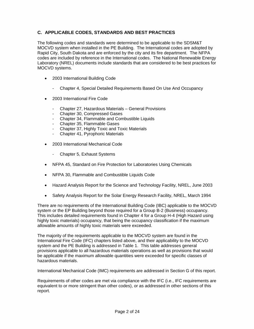
C. APPLICABLE CODES, STANDARDS AND BEST PRACTICES The following codes and standards were determined to be applicable to the SDSM&T MOCVD system when installed in the PE Building. The International codes are adopted by Rapid City, South Dakota and are enforced by the city and its fire department. The NFPA codes are included by reference in the International codes. The National Renewable Energy Laboratory (NREL) documents include standards that are considered to be best practices for MOCVD systems.
2003 International Building Code
- Chapter 4, Special Detailed Requirements Based On Use And Occupancy
2003 International Fire Code
- Chapter 27, Hazardous Materials – General Provisions - Chapter 30, Compressed Gases - Chapter 34, Flammable and Combustible Liquids - Chapter 35, Flammable Gases - Chapter 37, Highly Toxic and Toxic Materials - Chapter 41, Pyrophoric Materials
2003 International Mechanical Code
- Chapter 5, Exhaust Systems
NFPA 45, Standard on Fire Protection for Laboratories Using Chemicals
NFPA 30, Flammable and Combustible Liquids Code
Hazard Analysis Report for the Science and Technology Facility, NREL, June 2003
Safety Analysis Report for the Solar Energy Research Facility, NREL, March 1994 There are no requirements of the International Building Code (IBC) applicable to the MOCVD system or the EP Building beyond those required for a Group B-2 (Business) occupancy. This includes detailed requirements found in Chapter 4 for a Group H-4 (High Hazard using highly toxic materials) occupancy, that being the occupancy classification if the maximum allowable amounts of highly toxic materials were exceeded. The majority of the requirements applicable to the MOCVD system are found in the International Fire Code (IFC) chapters listed above, and their applicability to the MOCVD system and the PE Building is addressed in Table 1. This table addresses general provisions applicable to all hazardous materials operations as well as provisions that would be applicable if the maximum allowable quantities were exceeded for specific classes of hazardous materials. International Mechanical Code (IMC) requirements are addressed in Section G of this report. Requirements of other codes are met via compliance with the IFC (i.e., IFC requirements are equivalent to or more stringent than other codes), or as addressed in other sections of this report.

Table 1 – International Fire Code Application to Laboratory EP240
Page 3 of 24
IFC Reference
Requirement Applicability to EP240
Chapter 27 – Hazardous Materials – General Provisions
2701.3 Performance-based design alternative available Alternative approach not required
2703.1.3 Quantities not exceeding the maximum allowable quantity per control area shall be in accordance with Sections 2701 and 2703.
Quantities do not exceed maximum allowable.
2703.2.2
Piping, tubing, valves and fittings: (1) Compatible materials of adequate strength. (2) Labeled to identify material conveyed per ASME A13.1. (3) Manual valves or remotely activated emergency shutoff valve on supply
piping at (3.1) point of use, (3.2) cylinder source. (4) Valves in (3) accessible and identified by sign. (5) Backflow prevention or check valves where necessary for hazard or
prevention of discharge. (6) For health hazard 3 or 4 and flammability 4 gases or liquids above 15 psig,
leak detection and emergency shutoff or excess flow control provided – Excess flow control as close to bulk source as practical.
All conditions met. Both leak detection with automatic shutoff and excess flow
control used for item (6).
2703.2.2.2
For health hazard 3 or 4 gases or liquids: (1) Welded, threaded or flanged connections, except for gas plumbing within a
ventilated enclosure. (2) No piping or tubing in exit corridors.
All connections in ventilated enclosure and meet requirements of item (1).
2703.5 Hazard identification signs per NFPA 704 at entrance to storage and use locations.
Recommendation made for 704 signage.
2703.8.3.1 Fire barrier separations per IBC construction requirements. Recommendation made for EP240 door
upgrade.
2703.8.3.2 Percentage reduction of maximum allowable quantity based on floor level. EP240 is equivalent of first floor due to
grade-level entrance.
2703.8.3.4 Fire-resistance rating of fire barriers per Table 2703.8.3.2. One-hour rated separation is provided.
2703.8.6 Gas cabinet requirements if used to increase the maximum allowable quantity. Not Applicable - Gas cabinets and storage cabinets not used to increase
quantities. 2703.8.7
Storage cabinet requirements if used to increase the maximum allowable quantity.
2703.9 General safety precautions – Training, procedures, fire department liaison, etc. All requirements to be addressed in MOCVD Safe Operating Procedure
(SOP).
2703.10 Handling and transportation – Valve protection, outlet caps, carts and trucks, etc. All requirements to be addressed in
MOCVD SOP.
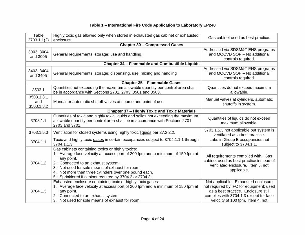
Table 1 – International Fire Code Application to Laboratory EP240
Page 4 of 24
Table 2703.1.1(2)
Highly toxic gas allowed only when stored in exhausted gas cabinet or exhausted enclosure.
Gas cabinet used as best practice.
Chapter 30 – Compressed Gases
3003, 3004 and 3005
General requirements; storage; use and handling. Addressed via SDSM&T EHS programs
and MOCVD SOP – No additional controls required.
Chapter 34 – Flammable and Combustible Liquids
3403, 3404 and 3405
General requirements; storage; dispensing, use, mixing and handling Addressed via SDSM&T EHS programs
and MOCVD SOP – No additional controls required.
Chapter 35 – Flammable Gases
3503.1 Quantities not exceeding the maximum allowable quantity per control area shall be in accordance with Sections 2701, 2703, 3501 and 3503.
Quantities do not exceed maximum allowable.
3503.1.3.1 and
3503.1.3.2 Manual or automatic shutoff valves at source and point of use.
Manual valves at cylinders, automatic shutoffs in system.
Chapter 37 – Highly Toxic and Toxic Materials
3703.1.1 Quantities of toxic and highly toxic liquids and solids not exceeding the maximum allowable quantity per control area shall be in accordance with Sections 2701, 2703 and 3701.
Quantities of liquids do not exceed maximum allowable.
3703.1.5.3 Ventilation for closed systems using highly toxic liquids per 27.2.2.2. 3703.1.5.3 not applicable but system is
ventilated as a best practice.
3704.1.1 Toxic and highly toxic gases in certain occupancies subject to 3704.1.1.1 through 3704.1.1.3.
Labs in Group B occupancies not subject to 3704.1.1.
3704.1.2
Gas cabinets containing toxics or highly toxics: 1. Average face velocity at access port of 200 fpm and a minimum of 150 fpm at
any point. 2. Connected to an exhaust system. 3. Not used for sole means of exhaust for room. 4. Not more than three cylinders over one pound each. 5. Sprinklered if cabinet required by 3704.2 or 3704.3.
All requirements complied with. Gas cabinet used as best practice instead of
ventilated enclosure. Item 5. not applicable.
3704.1.3
Exhausted enclosure containing toxic or highly toxic gases: 1. Average face velocity at access port of 200 fpm and a minimum of 150 fpm at
any point. 2. Connected to an exhaust system. 3. Not used for sole means of exhaust for room.
Not applicable. Exhausted enclosure not required by IFC for equipment; used
as a best practice. Enclosure still complies with 3704.1.3 except for face
velocity of 100 fpm. Item 4. not

Table 1 – International Fire Code Application to Laboratory EP240
Page 5 of 24
4. Sprinklered if cabinet required by 3704.2 or 3704.3. applicable.
3704.2.1.1 Quantities of toxic and highly toxic gas not exceeding the maximum allowable quantity per control area shall be in accordance with Sections 2701, 2703, 3701 and 3704.1.
Quantities of highly toxic gases may exceed the maximum allowable quantity
to reduce the required frequency of cylinder change-out. Regardless of the quantity of gas present the installation
meets or exceeds most requirements of 3704.2 as listed below.
3704.2.1.2 Quantities of toxic and highly toxic gas exceeding the maximum allowable quantity per control area shall be in accordance with Sections 3701, 3704.1, 3704.2 and Chapter 27.
Chapter 37 - Section 3704.2 – Toxic and Highly Toxic Gases Exceeding Maximum Allowable Quantities
3704.2.2.1 through
3704.2.2.3
General indoor requirements - When exceeding the maximum allowable quantities: 1. Cylinders located in cabinets, ventilated enclosures or gas rooms, 2. Rooms must have exhaust ventilation, 3. Provisions for leaking cylinders unless already in a gas cabinet.
Installation complies with these requirements.
3704.2.2.7
Treatment Systems - When exceeding the maximum allowable quantities, exhaust ventilation must be treated to maintain concentrations at one-half immediately dangerous to life and health (IDLH) at point of discharge to atmosphere in the event of accidental discharge. Multiple methods of treatment are allowed and criteria for discharge calculations are provided.
Reduced flow valves used, but they do not maintain discharge below one-half IDLH via dilution with exhaust air for all highly toxic gases. Additional controls
needed per Section G. below if the maximum allowable quantity is
exceeded.
3704.2.2.8 Emergency power or standby power - When exceeding the maximum allowable quantities, required for specific systems unless fail-safe engineered systems are installed.
Not known if emergency power is provided – Need to verify.
3704.2.2.9 Automatic Fire Detection and Local Alarm – Required when exceeding the maximum allowable quantities.
Building equipped with fire detection and alarm system.
3704.2.2.10 Gas Detection Systems - When exceeding the maximum allowable quantities, gas detection, alarm, and gas supply shut-down required.
MDA gas detection, alarm, and supply shut-down provided.
Chapter 41 – Pyrophoric Materials
4103.1 Quantities not exceeding the maximum allowable quantity per control area shall be in accordance with Sections 2701, 2703, 4101 and 4103.
Quantities do not exceed maximum allowable.
4103.1.1.1 and
4103.1.1.2 Manual or automatic shutoff valves at source and point of use.
Manual valves at cylinders, automatic shutoffs in system.

Page 6 of 24
D. LABORATORY LOCATION Two potential locations were identified for the MOCVD system; Laboratory EP240 in the EP Building and a presently unenclosed area in the Foundry Building. The latter facility is also located on the SDSM&T campus about a quarter mile from the EP Building. Both locations were visited and evaluated during the on-site activities. The Foundry Building potentially offers more flexible floor space (about 286 sq. ft.) for the MOCVD system and its support equipment. Existing equipment and operations could be rearranged within the building to accommodate the MOCVD system. A fire-rated enclosure would have to be constructed to separate the MOCVD system from other equipment and operations per code requirements, and a laboratory ventilation system would have to be installed. (See Sections F, Fire and Life Safety and G, Ventilation.) Offsetting the greater space available would be the presence of multiple ignition sources from current equipment and operations (e.g., multiple welding and cutting activities), a lower level of control of activities in the facility (but still acceptable), and the facility being located next to an athletic field at a low point on the campus. Laboratory EP240 provides similar floor space (287 sq. ft. total area), but existing equipment limits the possible arrangement of the MOCVD system. It has been demonstrated, however, that the MOCVD system can be placed in the room while maintaining adequate clearances around it as well as access to it and other equipment in that lab. The building is of more substantial construction, having CMU (concrete masonry unit) interior walls and reinforced concrete floor structures. Necessary fire separations can be maintained from adjoining labs and hallways with minor changes to the entry door. Portions of the required ventilation system are already installed in Lab EP240 and upper levels of the facility, and the point of discharge to the exterior is at approximately 30 feet above the adjoining grade level. A location for the toxic gas monitoring system is available that is remote from Laboratory EP240. Staff responsible for the MOCVD system is domiciled in the EP Building, which offers better oversight of laboratory conditions and adjoining operations. Neither facility is equipped with automatic fire sprinklers and both would be subject to the same limitations on quantities of hazardous materials in non-sprinklered facilities. Both facilities were well maintained and operations appeared well managed. Proposed layouts for the two areas are provided in Figures 1 and 2 below. Note that the locations of the toxic gas monitor and gas cylinders have been revised since Figure 1. was prepared. With appropriate facility modifications the MOCVD system could be installed and operated at an acceptable level of risk in either the Foundry Building or Laboratory EP240. However, EP240 appears to provide the better combination of features and should require less modification of the facility. The remainder of this assessment addresses the installation and operation of the MOCVD system in EP240.

Page 7 of 24
Figure 1 – EP240 Proposed Layout
(Note: Toxic Gas Monitor and Gas Cylinder locations have been revised.)
Figure 2 – Foundry Proposed Layout

Page 8 of 24
E. HAZARDOUS MATERIALS Materials, Location and Hazard Data The MOCVD system, as designed and constructed, has the ability to accommodate multiple gaseous and liquid sources for the growth of epitaxial layers, with these sources presenting varying types and degrees of hazards. Cylinders of hydrogen (H2), argon (Ar) and nitrogen (N2) will provide carrier gases and purge gases, respectively, For the planned operations of the system. H2 is a flammable and inert/asphyxiant gas and Ar and N2 are inert/asphyxiant gases. H2 and N2 are passed through a Nanochem purifier and a Matheson Model 8373V H2 purifier, respectively, both of which are incorporated into the MOCVD system. Growth gas sources will be provided by cylinders of arsine (AsH3) and phosphine (PH3), with the system currently structured for cylinders containing 10% concentrations of those gases in H2. AsH3 is highly toxic and flammable, and PH3 is highly toxic and pyrophoric. The original system design has all gas cylinders and the purifiers located within the MOCVD ventilated equipment enclosure. All pressure regulators and high and low pressure plumbing is within the equipment enclosure. Gas releases can occur at numerous points in the system plumbing; however the greatest risk occurs either during change-out of the AsH3 and PH3
cylinders or during manipulation of the high pressure side of the system due to the higher volume of concentrated gas that can be released. In accordance with current best practices the AsH3, PH3, and N2 cylinders are being relocated to a fire-rated gas cylinder cabinet purchased from a commercial manufacture. Excess flow valves and pressure regulators are also being relocated to a panel within the gas cylinder cabinet, thereby leaving only low pressure components of the system within the MOCVD equipment enclosure. This reduces the hazard present within the equipment enclosure, an area that is more likely to be accessed during system operations. It also provides better capture and exhaust of highly toxic gas in the event of a release during cylinder change out or a leak in a high pressure portion of the system. Air flow rates across access panels for the gas cylinder cabinet and the equipment enclosure, as well as total air flow through both enclosures is discussed in Section G, Ventilation. It is also planned to use cylinders of 100% AsH3 and PH3 rather than the 10% concentrations in H2 previously used. The diluted concentrations of the gases carry the same hazard ratings as the pure gases under the International codes, and the diluted and pure concentrations therefore have the same quantity limitations imposed by the codes. Using pure gases will allow combinations of smaller cylinders and extended time between cylinder change-out, both of which lower the risk present. Automatic and manual shut-off valves will be installed on the AsH3 and PH3 cylinders and at various points in the MOCVD system. These shut-off provisions meet the IFC requirements and included a highly visible, readily accessible, and clearly marked emergency shut-off button on the front of the system enclosure. Two N2 cylinders are being installed in the gas cabinet for purging of the AsH3 and PH3 plumbing. This is consistent with the best practice of avoiding cross contamination by having separate N2 cylinders for each of the highly toxic gas purge systems, as well as locating the purge gas cylinders as close as possible to the highly toxic gas source. It is noted that IFC Chapter 37 establishes a maximum of three toxic or highly toxic gas cylinders per ventilated gas cabinet. The cabinet in EP240 will contain two active highly toxic gas cylinders and may be used for temporary storage of a third highly toxic gas cylinder. The two N2 cylinders do not count towards the maximum established by IFC Chapter 37.

Page 9 of 24
To limit the maximum possible discharge the cylinders of AsH3 and PH3 will have flow limiting orifices installed in the valve cylinder outlets by the gas vendors, which qualify as „reduced flow valves‟ under IFC requirements. As a further control the excess flow shut-off valves built into the original system are being relocated to a position immediately after the cylinder valve, thereby limiting the number of plumbing connections potentially exposed to an uncontrolled flow of gas. It is noted that IFC requires highly toxic gases to be kept in ventilated gas cylinder cabinets, ventilated enclosures, or in chemical fume hoods. Of these three options the gas cylinder cabinets provide the highest level of protection due to increased air flow face velocity at access ports, the use of the cabinets for gas cylinders and high pressure system components only, and the increased frequency of staff access the equipment enclosure and fume hoods. As a best practice a ventilated gas cylinder cabinet will be used in Laboratory EP240. Further, flow restricting orifices are required by the IFC for highly toxic gases only if the maximum allowable quantity is exceeded. Provision of a cylinder cabinet and flow limiting orifices in EP240 exceeds the code requirements and represent best practices that reduce the risk present. The two H2 cylinders will be located outside the equipment enclosure in an appropriate mounting rack. This location is consistent with codes, standards and best practices. Up to 400 cubic feet (at STP) of flammable gas can be installed without local exhaust ventilation. This limit applies to multiple cylinders connected to a common manifold that could empty all cylinders in the event of a release. Each of the two H2 cylinder in EP240 will have a volume of about 200 cubic feet at STP and they will be connected to a common manifold. The Matheson hydrogen purifier will also be relocated to the exterior of the equipment enclosure. Research of Matheson product information has identified multiple safety controls built into the purifier unit, and a risk assessment included in the NREL Safety Analysis Report for the Solar Energy Research Facility determined that these units require no additional controls to maintain an acceptable level of risk. Liquid sources consist of bubblers containing trimethylgallium (TMGa), trimethylaluminum (TMAl), and ethyldimethylindium (EDMIn), each with a quantity of 100g. All three liquids are irritants, pyrophoric, mildly unstable, and mildly water reactive. Low pressure carrier gas is flowed through the bubblers in a closed system that carries dopants to the deposition chamber of the MOCVD system. Liquid will discharge from open ports on the bubblers only when there is a pressure differential across the inlet and outlet ports or when a gravity flow is created. The liquids burn on the surface that comes in contact with air, with the burning being more vigorous as the surface area increases. Incidents typically occur when bubblers are being changed out or otherwise are physically manipulated. The existing system has the liquid source bubblers located in a bottom level of the equipment enclosure. This location is consistent with current best practices in that spills cannot run to a lower level and the response to a spill is generally more effective at this level. It is recommended that noncombustible spill containment pans be provided for the liquid source bubblers, if they are not already present. Hazard data for each chemical is listed in Table 2. The primary source of data is the Hazardous Materials Expert (HMEx), a commercially available database recognized by the International Code Council. The hazard data provided by HMEx is consistent with definitions and criteria established by the International Code Council, NFPA and various safety and health organizations. Where the data in Table 1 conflicts with that found in MSDSs published by vendors it has been verified that the HMEx data is the most accurate.

Page 10 of 24
Table 2 - Chemical Hazard Data
Chemical CAS #
NFPA 704 Ratings
Hazard Categories Health Fire
Reac-tivity
Other
Arsine 7784-42-1 4 a
4 0 Highly Toxic, Flammable Gas
Phosphine 7803-51-12 4 a 4 0 Highly Toxic, Pyrophoric Gas
Hydrogen 1333-74-0 0 4 0 SA Flammable Gas, Simple
Asphyxiant Gas
TMA 75-24-1 2 4 2 W Irritant, Pyrophoric Liquid,
Unstable Reactive 2, Water Reactive 3
TMG 1445-79-0 2 4 2 W Irritant, Pyrophoric Liquid,
Unstable Reactive 2, Water Reactive 3
EDMIn Not Avail. b
2 4 2 W Irritant, Pyrophoric Liquid,
Unstable Reactive 2, Water Reactive 3
Nitrogen 7727-37-9 0 0 0 SA Simple Asphyxiant Gas
Argon 7440-37-1 0 0 0 SA Simple Asphyxiant Gas
Notes: b. Highly toxic gas must be used in approved exhausted gas cabinets, exhausted enclosures,
or under fume hoods per IFC. c. No hazard data has been located for ethyldimethylindium. Hazard ratings are estimated.
Analysis of Maximum Allowable Quantities The 2003 International Fire Code (IFC) establishes the maximum allowable quantity of materials per hazard category and Control Area. Laboratory EP 240 can qualify as its own Control Area within the IFC criteria (see Section F, Fire and Life Safety), and may maintain the maximum allowable quantity. The IFC further adjusts the maximum allowable quantity based on the floor level in the building and the level of fire suppression provided, and two issues concerning those topics were identified and resolved as follows:
The maximum allowable quantity of all categories of hazardous materials are reduced for floor levels above the first floor. This is due in part to the increased difficulty in responding to a fire above grade level. Laboratory EP240 is technically on the second floor of the EP Building and would be subject to a 25% reduction of maximum allowable quantities. A survey of the building determined that it is built into a slope that provides ground level access to the second floor on all of the south side and part of the east and west sides. Conversely, the first floor has ground level access on all of the north side and part of the east and west sides. (See Figures 3. and 4.) Table 2703.8.3.2 of the IFC specifies that the floor levels are “Above Grade Plane” rather than being the numbering applied within the building. This south side ground level access is considered to be a floor level at grade plane, and when combined with the additional controls that exceed code requirements (e.g., gas cylinder cabinet, flow restricting orifices) the floor level maintains an acceptable level of risk with Laboratory EP240 having 100% of the maximum allowable amounts.

Page 11 of 24
Figure 3. – EP Building – South Façade Figure 4. – EP Building – North Façade with second floor entry at grade plane. with second floor entry above grade plane.
The quantity of pyrophoric materials allowed is adjusted downward by the IFC if a building is not equipped with automatic fire sprinklers. The SDSM&T EH&S department has provided interpretation documents from the local fire department and the state engineer‟s office (Note: There is overlapping jurisdiction due to SDSM&T being a state-owned and operated school) indicating that they will allow the maximum allowable quantity of pyrophoric materials in non-sprinklered buildings.
At the 100% levels the quantities allowed per Control Area by the IFC for the hazard categories expected in EP240 are listed in Table 3.
Table 3 - Maximum Allowable Quantities Per Control Area – 2003 IFC
Hazard Category Storage a Use – Closed
System a
Materials Included In This Hazard Category
Highly Toxic Gas b
20 c.f. 20 c.f Arsine, Phosphine
Toxic Gas 810 c.f. 810 c.f.
Pyrophoric Gas 50 c.f. 10 c.f. Phosphine
Flammable Gas 1,000 c.f. 1,000 c.f. Arsine, Hydrogen
Highly Toxic Liquid 10 lbs. 10 lbs.
Toxic Liquid 500 lbs. 500 lbs.
Pyrophoric Liquid 4 lbs. 1 lbs. TMA, TMG, EDMIn
Flammable Liquid IA 30 gal. 30 gal.
Flammable Liquid IB & IC 120 gal. 120 gal.
Inert Gas No Limit No Limit Nitrogen, Argon
Notes: a. The aggregate quantity in storage and use shall not exceed the quantity listed for storage. b. Must be stored in approved exhausted gas cabinets or approved exhausted enclosures.
The limiting hazard category for the MOCVD system appears to be Highly Toxic Gas, for which an aggregate of 20 cubic feet is allowed for the AsH3 and PH3. An increase in the aggregate quantity of AsH3 and PH3 to 40 cubic feet may be warranted based on the additional controls and best practices being implemented. These controls address the majority of the IFC Chapter 37 requirements for quantities of highly toxic gases exceeding the maximum allowable and will be in place whether or not the maximum allowable quantity is exceeded. The code-required controls and additional best practice controls consist of:
Page 12 of 24
Cylinders located in ventilated gas cabinets (Rather than ventilated enclosure or chemical fume hood – Best practice)
Exhaust ventilation provided for Laboratory EP240 beyond gas cabinet and equipment enclosure exhaust.
All high pressure system components located in the gas cabinet (Best practice)
Welded tubing connections used where practicable in lieu of mechanical connections and all system connections located in gas cabinets or ventilated enclosures (Best practice)
Flow restricting orifices in cylinder valves and excess flow shut-off valves.
Automatic fire detection and alarm system throughout building.
Multi-point toxic gas monitor provided with automatic shutdown interlocks for alarm conditions
Relatively low hazardous material loading in the remainder of the building.
Building construction type that may exceed the building type requirement (i.e., all masonry interior partitions, reinforced concrete floor and framework, no unprotected floor or wall openings)
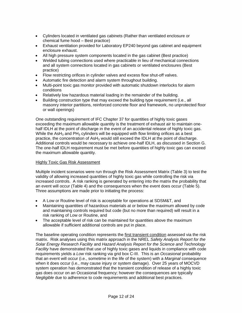
One outstanding requirement of IFC Chapter 37 for quantities of highly toxic gases exceeding the maximum allowable quantity is the treatment of exhaust air to maintain one-half IDLH at the point of discharge in the event of an accidental release of highly toxic gas. While the AsH3 and PH3 cylinders will be equipped with flow limiting orifices as a best practice, the concentration of AsH3 would still exceed the IDLH at the point of discharge. Additional controls would be necessary to achieve one-half IDLH, as discussed in Section G. The one-half IDLH requirement must be met before quantities of highly toxic gas can exceed the maximum allowable quantity. Highly Toxic Gas Risk Assessment Multiple incident scenarios were run through the Risk Assessment Matrix (Table 3) to test the validity of allowing increased quantities of highly toxic gas while controlling the risk via increased controls. A risk ranking is generated by entering into the matrix the probability that an event will occur (Table 4) and the consequences when the event does occur (Table 5). Three assumptions are made prior to initiating the process:
A Low or Routine level of risk is acceptable for operations at SDSM&T, and
Maintaining quantities of hazardous materials at or below the maximum allowed by code and maintaining controls required but code (but no more than required) will result in a risk ranking of Low or Routine, and
The acceptable level of risk can be maintained for quantities above the maximum allowable if sufficient additional controls are put in place.
The baseline operating condition represents the first transient condition assessed via the risk matrix. Risk analyses using this matrix approach in the NREL Safety Analysis Report for the Solar Energy Research Facility and Hazard Analysis Report for the Science and Technology Facility have demonstrated that use of highly toxic gases and liquids in compliance with code requirements yields a Low risk ranking via grid box C-III. This is an Occasional probability that an event will occur (i.e., sometime in the life of the system) with a Marginal consequence when it does occur (i.e., may cause injury or system damage). Over 25 years of MOCVD system operation has demonstrated that the transient condition of release of a highly toxic gas does occur on an Occasional frequency; however the consequences are typically Negligible due to adherence to code requirements and additional best practices.

Page 13 of 24
Table 3 – Risk Assessment Matrix
RISK ASSESSMENT
MATRIX
PROBABILITY
A Frequent
B Probable
C Occasional
D Remote
E Improbable
F Impossible
SE
VE
RIT
Y
I Catastrophic
High High High Moderate Low Routine
II Critical
High High Moderate Low Low Routine
III Marginal
Moderate Moderate Low Low Routine Routine
IV Negligible
Low Low Routine Routine Routine Routine
Table 4 - Probability That Potential Event Occurs
Level Annual Probability Potential Frequency
A Frequent > 1.0 Likely to occur many times during the life cycle
of the system (test/activity/operation).
B Probable = 0.1 to 1.0 Likely to occur several times during the life cycle
of the system.
C Occasional = 0.01 to 0.1 Likely to occur sometime during the life cycle
of the system.
D Remote = 0.0004 to 0.01 Not likely to occur in the life cycle of the system,
but possible.
E Improbable = 0.000001 to 0.0001 Probability of occurrence cannot be distinguished
from zero.
F Impossible < 0.000001 Physically impossible to occur.
Table 5 - Consequence When Potential Event Occurs
Category Description (Est. $ Amount) Potential Outcome
I Catastrophic = Loss > $1,000,000 May cause death or system loss.
II Critical = $100,000 to $1,000,000 May cause severe injury or occupational illness, or
moderate system damage.
III Marginal = $10,000 t0 $100,000 May cause injury or occupational illness, or
system damage.
IV Negligible < $10,000 Will not result in injury, occupational illness, or
significant damage.

Page 14 of 24
The second transient condition to be assessed consists of increasing the volume of highly toxic gases above the maximum allowable quantity without additional controls. Increasing the quantities (i.e., the same number of cylinders but larger volume) does not increase the probability that an event will occur, but does increase the potential consequence to Critical (i.e., severe injury or system damage). There are no changes to the number of cylinders, connections in the plumbing, or system operating pressures, so the probability does not change. The quantity of highly toxic gas potentially released is increased at least two-fold, which may overpower controls that meet basic code requirements and result in a more severe consequence. This results in a Moderate risk ranking via grid box C-II, which is an unacceptable level of risk per the assumptions established above. The third transient condition represents quantities of highly toxic gases above the maximum allowable, as in the second transient, but with the previously described additional controls in place to protect the system operators. The additional controls effectively reduce the opportunities for system operators to be exposed to the proposed larger volumes of highly toxic gas. This is achieved by limiting the flow of the gases via orifices and automatic shut-off valves, locating the cylinders and high pressure system components in a gas cabinet with a higher exhaust airflow rate (i.e., better capture and dilution capability), and providing continuous gas monitoring with automatic shut-down capability. These additional controls will continue to maintain an Occasional probability of a highly toxic gas release while restoring the consequences to a Marginal level. This brings the risk ranking back to Low, box C-III on the risk grid, which is an acceptable level. A fourth transient condition represents the same conditions as the third transient, but with consideration of the risk presented to persons exposed to concentrations of highly toxic gas at several times the IDLH after it has been discharged from the building. The probability remains at Occasional while the severity increases to Critical due to potential exposure to highly toxic gas concentrations exceeding one-half IDLH. This results in a Moderate risk ranking via box C-II on the risk grid, an unacceptable level of risk. This transient also represents a condition that is not in compliance with the IFC requirements for quantities of highly toxic gases exceeding the maximum allowable. IFC 3704.2.2.7 requires treatment of exhaust to one-half the IDLH at the point of discharge if the maximum allowable quantity is exceeded. Applying additional controls to the exhaust system to achieve one-half IDLH would lower the severity of this transient to Marginal, resulting in a Low risk ranking. Alternatively the quantities of highly toxic gas could be reduced to levels below the maximum allowed, thereby returning conditions to the first transient condition. A fifth transient condition must also be evaluated that is different than the first four transients; that being a leaking cylinder valve assembly during change-out of a highly toxic gas cylinder. Operating experience at NREL demonstrates that the likelihood of this transient occurring approaches Probable (i.e., likely to occur several times during the life of a system) with the consequences approaching Critical to Catastrophic (i.e., severe injury or death) due to the cylinder connections being manipulated with the gas cabinet door open. (In multiple instances during cylinder change-out an uncontained gas flow was experienced when the protective cap was removed from the cylinder valve outlet, and the cylinder valve was not able to stop the gas flow.) This transient condition was predicted during Safety Analysis Reviews conducted in 1991 and an acceptable level of risk was achieved through controls that reduced the consequences (e.g., use of SCBA during cylinder change-out) as well as controls that reduced the probability. In the latter case larger volume gas cylinders were used to reduce the frequency of cylinder change-out, thereby reducing the probability of this transient occurring. A similar approach is recommended for the MOCVD system in EP240; i.e., reduce the frequency of cylinder change-out by increasing the size of the highly toxic

Page 15 of 24
gas cylinders to the maximum consistent with the controls in place, and apply best practices during cylinder change-out. It is noted that increasing the quantities of highly toxic gas to twice the maximum allowable (i.e., from 20 cubic feet to 40 cubic feet) will still maintain the pyrophoric gas volume (i.e., PH3) below the maximum allowable quantity of 50 cubic feet. Increasing the quantity of PH3 above 50 cubic feet was not part of the risk assessment due to the implications for the use of pyrophorics in non-sprinklered buildings. Based on this risk assessment, an acceptable level of risk (i.e., Low risk ranking) can be readily maintained while operating the MOCVD syatem at or below the maximum allowable quantities of hazardous materials. Increasing the volume of highly toxic gas to double the maximum allowable amount (i.e., 40 cubic feet) will create an unacceptable level of risk that can be resolved by reducing the concentration of the gas at the point of discharge. A recommendation is made that the actual quantity of highly toxic gas maintained in EP240 be evaluated against the resultant frequency of cylinder change-out, and that the most practicable combination of cylinder size, change-out frequency, and ventilation controls be implemented. Toxic Gas Monitoring Monitoring for releases of highly toxic gases is provided via an MDA System 16 gas detection unit having four point monitoring capability. The unit is configured to detect gaseous hydrides including AsH3 and PH3 and has high and low-level detection and alarm capabilities. It is planned that the four monitoring points will draw air samples from the gas cylinder cabinet, the equipment enclosure, the laboratory air exhaust, and the laboratory ambient air. Alarm and response protocols are being developed consistent with practices established for similar MOCVD operations. A recommendation is made that the MDA monitoring unit be located in a different room than the MOCVD system to allow responders to access the MDA readouts during an alarm situation without being potentially exposed to a hazardous atmosphere.

Page 16 of 24
F. FIRE AND LIFE SAFETY IFC Table 2703.8.3.2 requires fire barriers separating Control Areas from other areas of the building to have a one-hour fire-resistance rating for floors one through three above the grade plane. Laboratory EP240 will be considered its own Control Area. Existing floor and wall assemblies appear to maintain a one-hour fire rating due to the reinforced concrete and concrete masonry unit construction, respectively. See Figure 5 for typical floor and wall construction. All visible floor and wall penetrations were properly protected, however some areas of the overhead floor construction and upper portions of the walls (i.e., above the drop ceiling) could not be observed at the time of the survey. A recommendation is made that a thorough inspection be conducted of the overhead floor construction and upper portions of the walls for unprotected penetrations.
Figure 5. – Typical floor and wall construction in Figure 6. – EP240 Door room without drop ceiling. The entry door to EP240 is not labeled and therefore does not qualify as a 45-minute fire-rated door, as required for protection of an opening in a one-hour rated wall assembly. The door appears to be of solid wood core construction and the window in the door and the transom above the door are wired glass. The window in the door is secured by wooden trim. The door frame is metal. The door is not equipped with a self-closing mechanism. See Figure 6. A recommendation is made that the authority having jurisdiction be contacted to determine what minimum upgrades should be made to the door assembly. This approach recognizes that the current door assembly may be grandfathered under the code in effect when the EP Building was constructed. Possible actions include:
Replace the door, transom and frame assembly with a 45-minute labeled unit equipped with a self-closing mechanism.
Replace the door with a 45-minute labeled unit in the existing frame, install a self-closing mechanism, and replace the transom window with materials maintaining the necessary fire rating.
Install a self-closing mechanism on the existing door and replace the transom window with materials maintaining the necessary fire rating.
Install a self-closing mechanism on the existing door. From a risk acceptance standpoint, the second or third listed options are preferred.

Page 17 of 24
The EP Building is equipped with a fire detection and alarm system with 135 degree fixed-temperature and rate-of-rise detectors (ROR), manual pull stations, and local alarms. See Figure 7. The alarm panel is connected to a central monitoring station. This system meets the IFC 37.2.2.9 requirement that an automatic fie detection system and local alarms be provided when the maximum allowable quantity of highly toxic gases is exceeded. The MDA toxic gas monitoring system for EP240 is tied into the fire alarm panel and activates the building fire alarm for specific toxic gas alarm conditions. This interconnection of the gas and fire alarm systems meets the IFC 37.2.2.10.1 requirement that toxic gas alarms be monitored at a central location if the maximum allowable quantities are exceeded.
Figure 7. – Fixed temperature and ROR detector. An appropriate number and type of portable fire extinguishers were observed throughout the building. A recommendation is made that a dry chemical extinguisher and a supply of vitrified clay be provided in EP240. The vitrified clay is used to cover spills of pyrophoric liquids.
Page 18 of 24
G. VENTILATION Laboratory Air Exchange Rate Based on current best practices a basic air exchange rate of 1.0 standard cubic foot per minute (scfm) per square foot of floor area is recommended for Lab EP240. This is the ventilation rate required by the International Building Code and International Mechanical Code for an H-5 occupancy (i.e., semiconductor fabrication facilities and comparable research and development areas using hazardous production materials in excess of the exempt allowable quantities). Although the exempt allowable quantities will not be exceeded in Lab EP240 this is still considered an appropriate design basis. For a room with dimensions of 11.5 feet by 25 feet (287.5 sq ft floor area) this would equate to a lab air exhaust rate of about 300 scfm. The actual air exchange rate for EP240 will be higher due to local exhaust ventilation (LEV) systems within the lab, as described in following sections; 300 scfm is considered the basic minimum. Using traditional measures of air changes per hour (ACH), for a 3,600 cu ft lab volume this would represent five (5) ACH. An ACH between four (4) and twelve (12) is recommended for laboratories by various codes and standards (e.g., ASHRAE, OSHA, NFPA 45) with the actual ACH being dependent on the hazard present. Current practice is to design LEV systems for specific hazards within a lab rather than relying solely on a certain ACH to maintain a safe atmosphere. Chemical Fume Hood Current best practice for chemical fume hoods is to maintain an average air exhaust velocity of 80 to 100 foot per minute (fpm) across the open face of the hood with the sash adjusted to the approved working height. A sash height of 18 inches is generally prescribed as the best height for protection of the workers while still allowing access to the hood. The actual exhaust velocity should be appropriate to the level of hazard presented by operations in the hood. SDSM&T has established a standard face velocity of 100 fpm for chemical fume hoods. At a sash height of 18 inches a four (4) foot wide hood will have a face area of six (6) square feet. (Note: The width of the hood face should be verified.) A face velocity of 100 fpm will require an exhaust flow rate of 600 cfm. Note that this exceeds the basic laboratory air exchange rate described in the previous section. Gas Cylinder Storage Cabinet Due to the presence of highly toxic gases a ventilated gas cylinder storage cabinet is recommended as a LEV system that will reduce the risk presented to workers. IFC Chapters 27 and 37 require that cylinders of highly toxic gases be kept in a ventilated gas cabinet, a ventilated enclosure, or a ventilated fume hood. A gas cabinet is recommended due to the higher level of protection it provides during cylinder change-out and normal operations. The Safety Equipment Model 7200 two-cylinder gas storage cabinet is being considered for Lab EP240. Exhaust flow and static pressure requirement are not identified for this hood by Safety Equipment. The access panel on the Model 7200 measures 17 inches by 13 inches for an area of 1.53 square feet. To maintain an average flow of 200 fpm across the area of the open access port, as required by the IFC, an exhaust flow rate of 307 cfm is required. To maintain flow through the inlet port at the bottom of the cabinet while the access port is open it is

Page 19 of 24
recommended that a total exhaust rate of 350 cfm be provided for the gas cabinet; i.e., about 50 cfm more than is required for access port flow. This flow is added to the exhaust described above for the chemical fume hood, for a total exhaust of 950 cfm. MOCVD Equipment Enclosure The metal-organic chemical vapor deposition (MOCVD) system is enclosed in a ventilated, heavy gauge steel cabinet that creates an LEV system. The main cabinet contains gas and liquid distribution systems, liquid sources and control equipment and has a footprint of about 15 feet by 2.5 feet. An extension to the cabinet containing the deposition chamber and vacuum pump has a footprint of about 4 feet by 2.5 feet. Total area of the cabinet is just under 50 square feet and at 6.5 feet tall it has an internal volume of about 325 cubic feet. An exhaust port is centrally located on the top of the cabinet and small air inlet ports are provided at the bottom of each cabinet compartment. This arrangement should provide an effective airflow sweep of the interior of the cabinet. The cabinet is equipped with removable Plexiglas viewing panels around the deposition chamber and removable steel access panels for other compartments of the cabinet. The present size of the removable panels (about 3 ft by 4 ft and larger) makes the maintenance of a 100 fpm average face velocity with a panel removed impracticable without excessively high exhaust flow rates. Maintaining an evenly distributed exhaust velocity over such a large area is also difficult. It is recommended that smaller access panels with hinged doors be installed at necessary points, such as at the substrate loading chamber and at regulator adjusting and valve manipulation points. Access panels with a nominal size of nine (9) inches by nine (9) inches (0.5626 sq ft) should provide adequate single-handed access while maintaining an effective face velocity, provided only one access panel is open at a time. It should be ensured that there are adequate openings in the walls separating internal compartments of the cabinet to provide for adequate face velocity at access panels located at a distance from the exhaust port, particularly for the compartment containing the growth chamber. An exhaust flow rate of 100 cfm is recommended for the equipment enclosure cabinet. This provides about 2.0 cfm per square foot of footprint and about 20 ACH for the cabinet interior. Opening an access panel will require about 60 cfm of exhaust flow, leaving 40 cfm for ventilation of the cabinet interior during these transient periods. There is a possibility that ventilation dead spots may occur inside the cabinet during these transient periods, and they should therefore be restricted to the shortest time period possible. Combined with the previously described exhaust flows for the chemical fume hood and gas cylinder cabinet, the total exhaust flow requirement for Lab EP240 is now 1,050 cfm. Ambient Air Exhaust To promote mixing of air throughout Lab EP240 and to prevent ventilation dead spots within the room it is recommended that 100 cfm of exhaust air be provided via one or more ceiling mounted exhaust vents. This also assures compliance with IFC 3704.1.2 and 3704.2.2.2 requirements that exhaust capacity be provided for the ambient room air. This will bring the total exhaust flow requirement for Lab EP240 to 1,150 cfm. Laboratory Make-up Air and Building Balance The air flow rates are not known for the existing exhaust and make-up air systems in Lab EP240. It is recommended that all exhaust air from EP240 be vented to the exterior of the
Page 20 of 24
building; recirculation of some or all of the exhaust air should be avoided due to the possibility of contaminants. The make-up air to EP240 should be adjusted to maintain a slight negative air pressure relative to the adjoining exit corridor. That is, slightly less make up air should be provided than is exhausted so that the remaining air flows from the lower hazard area, the hallway, to the higher hazard area, the lab. A standard pressure balance for similar research laboratories is to maintain a static pressure differential of 0.03 to 0.05 inches of water between the laboratory and hallway.
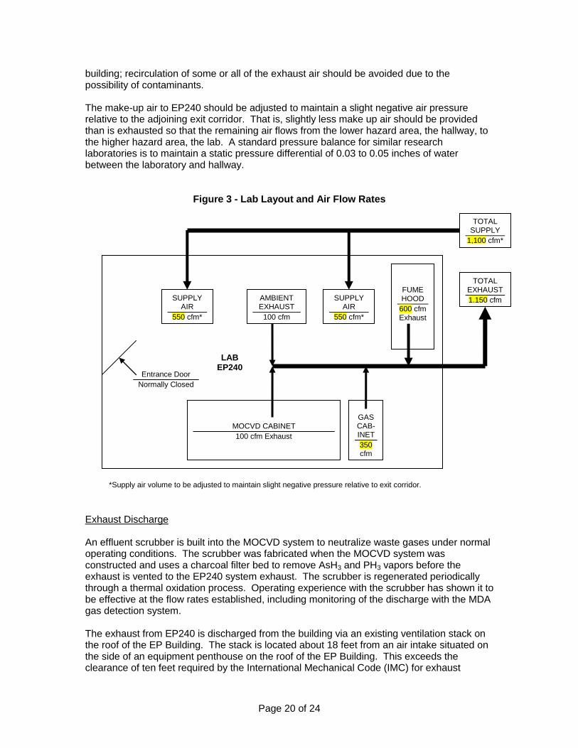
Figure 3 - Lab Layout and Air Flow Rates
Exhaust Discharge An effluent scrubber is built into the MOCVD system to neutralize waste gases under normal operating conditions. The scrubber was fabricated when the MOCVD system was constructed and uses a charcoal filter bed to remove AsH3 and PH3 vapors before the exhaust is vented to the EP240 system exhaust. The scrubber is regenerated periodically through a thermal oxidation process. Operating experience with the scrubber has shown it to be effective at the flow rates established, including monitoring of the discharge with the MDA gas detection system. The exhaust from EP240 is discharged from the building via an existing ventilation stack on the roof of the EP Building. The stack is located about 18 feet from an air intake situated on the side of an equipment penthouse on the roof of the EP Building. This exceeds the clearance of ten feet required by the International Mechanical Code (IMC) for exhaust
FUME HOOD
600 cfm Exhaust
MOCVD CABINET
100 cfm Exhaust
GAS CAB-INET
350 cfm
AMBIENT EXHAUST
100 cfm
TOTAL EXHAUST
1,150 cfm SUPPLY AIR
550 cfm*
SUPPLY AIR
550 cfm*
TOTAL SUPPLY
1,100 cfm*
LAB EP240
Entrance Door
Normally Closed
*Supply air volume to be adjusted to maintain slight negative pressure relative to exit corridor.
Page 21 of 24
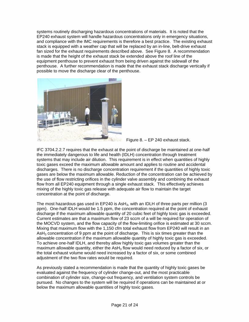
systems routinely discharging hazardous concentrations of materials. It is noted that the EP240 exhaust system will handle hazardous concentrations only in emergency situations, and compliance with the IMC requirements is therefore a best practice. The existing exhaust stack is equipped with a weather cap that will be replaced by an in-line, belt-drive exhaust fan sized for the exhaust requirements described above. See Figure 8. A recommendation is made that the height of the exhaust stack be extended above the roof line of the equipment penthouse to prevent exhaust from being driven against the sidewall of the penthouse. A further recommendation is made that the exhaust stack discharge vertically if possible to move the discharge clear of the penthouse.
Figure 8. – EP 240 exhaust stack. IFC 3704.2.2.7 requires that the exhaust at the point of discharge be maintained at one-half the immediately dangerous to life and health (IDLH) concentration through treatment systems that may include air dilution. This requirement is in effect when quantities of highly toxic gases exceed the maximum allowable amount and applies to routine and accidental discharges. There is no discharge concentration requirement if the quantities of highly toxic gases are below the maximum allowable. Reduction of the concentration can be achieved by the use of flow restricting orifices in the cylinder valve assembly and combining the exhaust flow from all EP240 equipment through a single exhaust stack. This effectively achieves mixing of the highly toxic gas release with adequate air flow to maintain the target concentration at the point of discharge. The most hazardous gas used in EP240 is AsH3, with an IDLH of three parts per million (3 ppm). One-half IDLH would be 1.5 ppm, the concentration required at the point of exhaust discharge if the maximum allowable quantity of 20 cubic feet of highly toxic gas is exceeded. Current estimates are that a maximum flow of 23 sccm of a will be required for operation of the MOCVD system, and the flow capacity of the flow-limiting orifice is estimated at 30 sccm. Mixing that maximum flow with the 1,150 cfm total exhaust flow from EP240 will result in an AsH3 concentration of 9 ppm at the point of discharge. This is six times greater than the allowable concentration if the maximum allowable quantity of highly toxic gas is exceeded. To achieve one-half IDLH, and thereby allow highly toxic gas volumes greater than the maximum allowable quantity, either the AsH3 flow would need reduced by a factor of six, or the total exhaust volume would need increased by a factor of six, or some combined adjustment of the two flow rates would be required. As previously stated a recommendation is made that the quantity of highly toxic gases be evaluated against the frequency of cylinder change-out, and the most practicable combination of cylinder size, change-out frequency, and ventilation system controls be pursued. No changes to the system will be required if operations can be maintained at or below the maximum allowable quantities of highly toxic gases.

Page 22 of 24
Consideration was also given to the risk presented to other buildings by exhaust discharge from EP 240. Due to the height of the EP Building and the terrain, the roofs of adjoining SDSM&T facilities are at or below the level of the EP240 exhaust stack. See Figures 9. and 10. taken from the roof of the EP Building. Note that the roof of the Science Building is equipped with about ten similar laboratory exhaust stacks. When the EP240 exhaust stack is extended above the equipment penthouse roof line it will also be higher than the rooflines of any buildings within about a quarter mile. When combined with the one-half IDLH discharge requirement the height and location of the EP240 exhaust stack makes it extremely unlikely that hazardous materials exposures could occur at other buildings or ground level around the EP Building.
Figure 9. – Science Building Roof Figure 10. – Field House in background International Mechanical Code Requirements Chapter 5 of the International Mechanical Code (IMC) lists requirements for exhaust systems, with Section 502.8 addressing general hazardous materials requirements. Section 501 specifies clearances between exhaust discharge points and operable openings (e.g., windows, air intakes), roofs, grade level, etc. As previously noted, these clearances are met or exceeded. Section 502.9.7 is specific to toxic and highly toxic gases and is identical to gas cabinet and ventilated enclosure requirements already addressed under the IFC. Section 502.9.8 is specific to toxic and highly toxic gases that exceed the maximum allowable quantities and also is identical to requirements already addressed under the IFC. Section 510 provides requirements for hazardous exhaust systems, those being systems that will exhaust known concentrations of hazardous materials presenting a physical or health hazard, as defined in the IMC, on a regular basis. The EP240 exhaust system would convey these concentrations of hazardous materials only in emergency situations, particularly highly toxic gases, and controls are in place to limit the discharge to below one-half IDLH as previously described. Other requirements of the IMC should be addressed during the design phase for the exhaust fan, ductwork, etc.

Page 23 of 24
H. OTHER HAZARDS Vacuum Systems The MOCVD system reaction chamber operates under vacuum within a pressure range of 0.01 to 0.1 atmosphere. Standard practices have been applied to the arrangement and operation of the vacuum pump and system components, all of which are commercially available. The reaction chamber is relatively small and is located behind Plexiglas vision panels, thereby limiting the exposure in the event of a chamber implosion. Radiofrequency Radiation The reaction chamber is heated by inductive coupling from a radiofrequency (RF) magnetic field created by an RF loop around the chamber. An RF generator is located within the MOCVD system enclosure. The generator was fabricated during the original construction of the MOCVD system and operates at a fixed frequency and power setting. A recommendation is made that monitoring of the MOCVD system be conducted to determine that the RF field is properly contained and there is no unacceptable exposure presented to the system operators. I. OPERATING PROCEDURES A Safe Operating Procedure (SOP) is being developed for the MOCVD system using a format that identifies the hazards presented by the operations and the procedures required to control those hazards. An operating manual was developed when the MOCVD system was originally constructed and operated. pertinent information from that manual is being incorporated into the SOP with necessary additions to address revisions made to the system. When the draft SOP is completed it will be reviewed and comments submitted as part of the scope of this project.

Page 24 of 24
J. SUMMARY OF RECOMMENDATIONS 1. Cylinders of highly toxic gases and their accompanying cylinders of inert purge gases
should be located in a ventilated gas cylinder cabinet to provide the maximum possible level of control in the event of an accidental gas release. It is further recommended that the high pressure components of the gas distribution system also be located within the gas cylinder cabinet as far as practicable.
2. The actual quantity of highly toxic gas maintained in EP240 should be evaluated against
the resultant frequency of cylinder change-out, and the most practicable combination of cylinder size, change-out frequency, and ventilation controls should be implemented consistent with an acceptable level of risk. Additional controls will be required to maintain the concentration of arsine below one-half IDLH at the point of discharge from the building if this combination results in the maximum allowable quantity of highly toxic gas being exceeded, as established by the IFC.
3. The MDA toxic gas monitor should be located outside of EP240 to prevent possible
exposure to hazardous atmospheres for persons accessing the MDA read-outs. 4. The floor and wall structure above the drop ceiling in EP240 should be inspected to
determine if any unprotected penetrations exist, and any penetrations identified should be protected to maintain the one-hour fire separation around EP240.
5. The door to EP240 should be upgraded to maintain the one-hour fire separation around
EP240. Dependent on all or part of the existing door assembly being „grandfathered‟ by the authority having jurisdiction possible upgrades include:
Replace the door, transom and frame assembly with a 45-minute labeled unit equipped with a self-closing mechanism.
Replace the door with a 45-minute labeled unit in the existing frame, install a self-closing mechanism, and replace the transom window with materials maintaining the necessary fire rating.
Install a self-closing mechanism on the existing door and replace the transom window with materials maintaining the necessary fire rating.
Install a self-closing mechanism on the existing door. 6. A portable fire extinguisher with a minimum rating of 2A:20B:C should be installed on a
wall mount inside EP240 to provide first-response extinguishing capabilities. This capability should be augmented by a placing a supply of vitrified clay (e.g., Kitty Litter) in EP240 for use in the event of a pyrophoric liquid release.
7. The exhaust stack for EP240 located on the roof of the EP Building should be extended
above the height of the adjoining equipment penthouse to minimize the potential of exhaust discharge being re-entrained against the side of the penthouse. It is further recommended that the EP240 exhaust stack discharge vertically, if possible, to maximize the movement of the exhaust away from the EP Building.
8. Monitoring for stray radiofrequency (RF) fields should be conducted with appropriate
equipment when the RF unit is operational to verify that the MOCVD system operators are not exposed to hazardous RF emissions.
9. An NFPA 704 placard should be installed at the entrance to EP240 to provide hazard
information to responding emergency personnel.
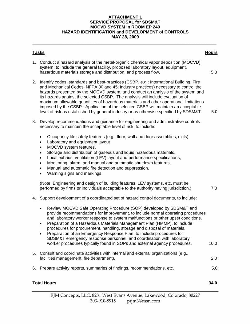
ATTACHMENT 1 SERVICE PROPOSAL for SDSM&T MOCVD SYSTEM in ROOM EP 240
HAZARD IDENTIFICATION and DEVELOPMENT of CONTROLS MAY 28, 2009
___________________________________________________________________________
____________________________________________________________________________ RJM Concepts, LLC, 8281 West Evans Avenue, Lakewood, Colorado, 80227
303-910-8915 [email protected]
Tasks Hours 1. Conduct a hazard analysis of the metal-organic chemical vapor deposition (MOCVD)
system, to include the general facility, proposed laboratory layout, equipment, hazardous materials storage and distribution, and process flow. 5.0
2. Identify codes, standards and best-practices (CSBP, e.g.: International Building, Fire
and Mechanical Codes; NFPA 30 and 45; industry practices) necessary to control the hazards presented by the MOCVD system, and conduct an analysis of the system and its hazards against the selected CSBP. The analysis will include evaluation of maximum allowable quantities of hazardous materials and other operational limitations imposed by the CSBP. Application of the selected CSBP will maintain an acceptable level of risk as established by general industry or as otherwise specified by SDSM&T. 5.0
3. Develop recommendations and guidance for engineering and administrative controls
necessary to maintain the acceptable level of risk, to include:
Occupancy life safety features (e.g.: floor, wall and door assemblies; exits)
Laboratory and equipment layout
MOCVD system features,
Storage and distribution of gaseous and liquid hazardous materials,
Local exhaust ventilation (LEV) layout and performance specifications,
Monitoring, alarm, and manual and automatic shutdown features,
Manual and automatic fire detection and suppression.
Warning signs and markings.
(Note: Engineering and design of building features, LEV systems, etc. must be performed by firms or individuals acceptable to the authority having jurisdiction.) 7.0
4. Support development of a coordinated set of hazard control documents, to include:
Review MOCVD Safe Operating Procedure (SOP) developed by SDSM&T and provide recommendations for improvement, to include normal operating procedures and laboratory worker response to system malfunctions or other upset conditions.
Preparation of a Hazardous Materials Management Plan (HMMP), to include procedures for procurement, handling, storage and disposal of materials.
Preparation of an Emergency Response Plan, to include procedures for SDSM&T emergency response personnel, and coordination with laboratory worker procedures typically found in SOPs and external agency procedures. 10.0
5. Consult and coordinate activities with internal and external organizations (e.g.,
facilities management, fire department). 2.0 6. Prepare activity reports, summaries of findings, recommendations, etc. 5.0 Total Hours 34.0