laboratory - cole-parmer€¦ · laboratory muffle furnaces preheating furnaces ashing furnaces...
TRANSCRIPT
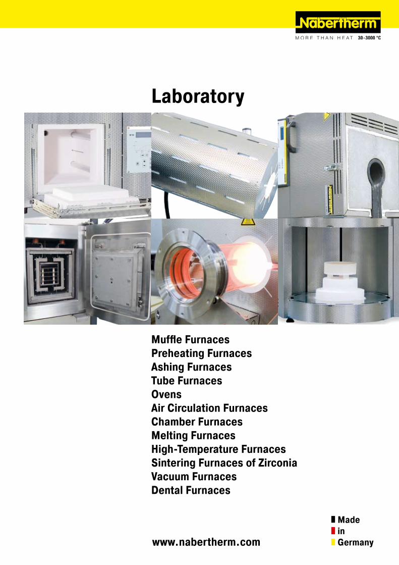
Laboratory
Muffle FurnacesPreheating FurnacesAshing FurnacesTube FurnacesOvensAir Circulation FurnacesChamber FurnacesMelting FurnacesHigh-Temperature FurnacesSintering Furnaces of ZirconiaVacuum FurnacesDental Furnaces
www.nabertherm.com
MadeinGermany
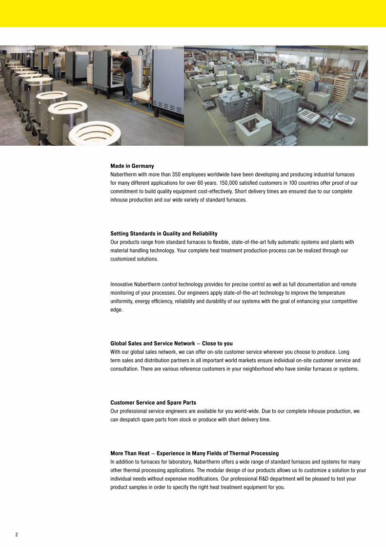
Made in GermanyNabertherm with more than 350 employees worldwide have been developing and producing industrial furnaces for many different applications for over 60 years. 150,000 satisfied customers in 100 countries offer proof of our commitment to build quality equipment cost-effectively. Short delivery times are ensured due to our complete inhouse production and our wide variety of standard furnaces.
Setting Standards in Quality and ReliabilityOur products range from standard furnaces to flexible, state-of-the-art fully automatic systems and plants with material handling technology. Your complete heat treatment production process can be realized through our customized solutions.
Innovative Nabertherm control technology provides for precise control as well as full documentation and remote monitoring of your processes. Our engineers apply state-of-the-art technology to improve the temperature uniformity, energy efficiency, reliability and durability of our systems with the goal of enhancing your competitive edge.
Global Sales and Service Network – Close to youWith our global sales network, we can offer on-site customer service wherever you choose to produce. Long term sales and distribution partners in all important world markets ensure individual on-site customer service and consultation. There are various reference customers in your neighborhood who have similar furnaces or systems.
Customer Service and Spare PartsOur professional service engineers are available for you world-wide. Due to our complete inhouse production, we can despatch spare parts from stock or produce with short delivery time.
More Than Heat – Experience in Many Fields of Thermal ProcessingIn addition to furnaces for laboratory, Nabertherm offers a wide range of standard furnaces and systems for many other thermal processing applications. The modular design of our products allows us to customize a solution to your individual needs without expensive modifications. Our professional R&D department will be pleased to test your product samples in order to specify the right heat treatment equipment for you.
�
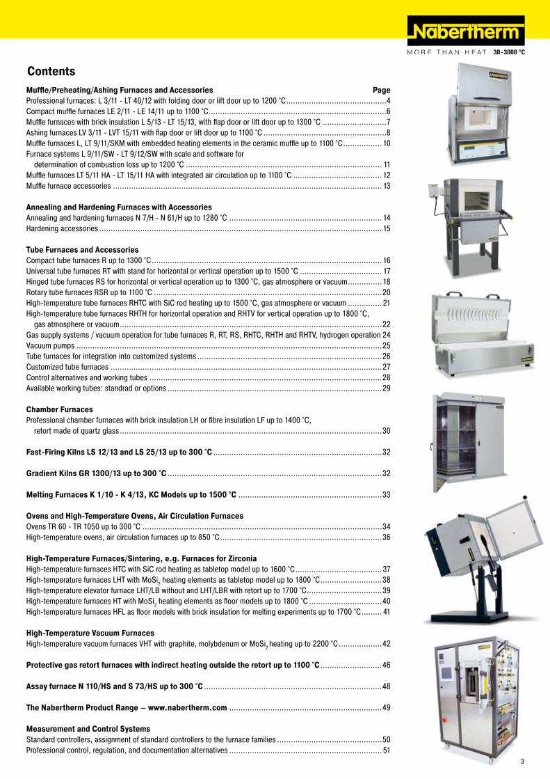
ContentsMuffle/Preheating/Ashing Furnaces and Accessories PageProfessional furnaces: L 3/11 - LT 40/1� with folding door or lift door up to 1�00 °C ............................................4Compact muffle furnaces LE �/11 - LE 14/11 up to 1100 °C ..............................................................................6Muffle furnaces with brick insulation L 5/13 - LT 15/13, with flap door or lift door up to 1300 °C ............................7Ashing furnaces LV 3/11 - LVT 15/11 with flap door or lift door up to 1100 °C ......................................................8Muffle furnaces L, LT 9/11/SKM with embedded heating elements in the ceramic muffle up to 1100 °C .................10Furnace systems L 9/11/SW - LT 9/1�/SW with scale and software for determination of combustion loss up to 1�00 °C ...................................................................................... 11Muffle furnaces LT 5/11 HA - LT 15/11 HA with integrated air circulation up to 1100 °C .......................................1�Muffle furnace accessories ...................................................................................................................... 13
Annealing and Hardening Furnaces with AccessoriesAnnealing and hardening furnaces N 7/H - N 61/H up to 1�80 °C ................................................................... 14Hardening accessories ............................................................................................................................15
Tube Furnaces and AccessoriesCompact tube furnaces R up to 1300 °C .....................................................................................................16Universal tube furnaces RT with stand for horizontal or vertical operation up to 1500 °C .................................... 17Hinged tube furnaces RS for horizontal or vertical operation up to 1300 °C, gas atmosphere or vacuum ...............18Rotary tube furnaces RSR up to 1100 °C ....................................................................................................�0High-temperature tube furnaces RHTC with SiC rod heating up to 1500 °C, gas atmosphere or vacuum ...............�1High-temperature tube furnaces RHTH for horizontal operation and RHTV for vertical operation up to 1800 °C, gas atmosphere or vacuum ...................................................................................................................��Gas supply systems / vacuum operation for tube furnaces R, RT, RS, RHTC, RHTH and RHTV, hydrogen operation �4Vacuum pumps ......................................................................................................................................�5Tube furnaces for integration into customized systems .................................................................................�6Customized tube furnaces .......................................................................................................................�7Control alternatives and working tubes ......................................................................................................�8Available working tubes: standrad or options ..............................................................................................�9
Chamber FurnacesProfessional chamber furnaces with brick insulation LH or fibre insulation LF up to 1400 °C, retort made of quartz glass ...................................................................................................................30
Fast-Firing Kilns LS 12/13 and LS 25/13 up to 300 °C ..........................................................................3�
Gradient Kilns GR 1300/13 up to 300 °C ..............................................................................................3�
Melting Furnaces K 1/10 - K 4/13, KC Models up to 1500 °C ...............................................................33
Ovens and High-Temperature Ovens, Air Circulation FurnacesOvens TR 60 - TR 1050 up to 300 °C .........................................................................................................34High-temperature ovens, air circulation furnaces up to 850 °C .......................................................................36
High-Temperature Furnaces/Sintering, e.g. Furnaces for ZirconiaHigh-temperature furnaces HTC with SiC rod heating as tabletop model up to 1600 °C ......................................37High-temperature furnaces LHT with MoSi� heating elements as tabletop model up to 1800 °C ...........................38High-temperature elevator furnace LHT/LB without and LHT/LBR with retort up to 1700 °C .................................39High-temperature furnaces HT with MoSi� heating elements as floor models up to 1800 °C ................................40High-temperature furnaces HFL as floor models with brick insulation for melting experiments up to 1700 °C ......... 41
High-Temperature Vacuum FurnacesHigh-temperature vacuum furnaces VHT with graphite, molybdenum or MoSi� heating up to ��00 °C ...................4�
Protective gas retort furnaces with indirect heating outside the retort up to 1100 °C ...........................46
Assay furnace N 110/HS and S 73/HS up to 300 °C ..............................................................................48
The Nabertherm Product Range – www.nabertherm.com ...................................................................49
Measurement and Control SystemsStandard controllers, assignment of standard controllers to the furnace families ..............................................50Professional control, regulation, and documentation alternatives ................................................................... 51
3
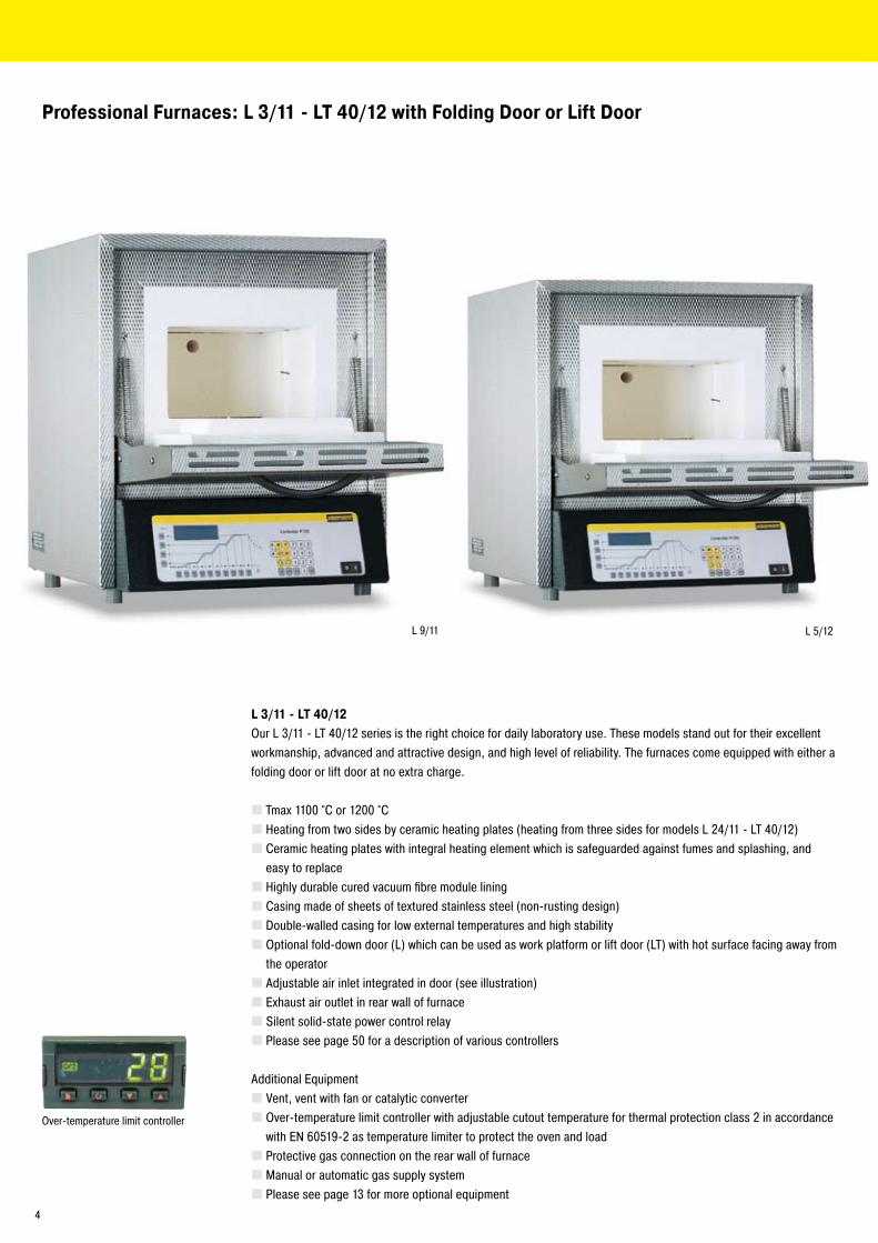
L 9/11 L 5/1�
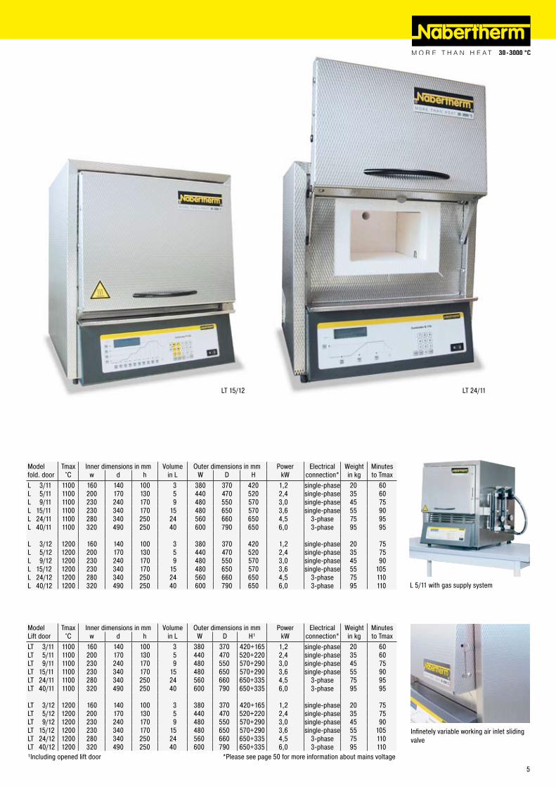
Professional Furnaces: L 3/11 - LT 40/12 with Folding Door or Lift Door
L 3/11 - LT 40/12Our L 3/11 - LT 40/1� series is the right choice for daily laboratory use. These models stand out for their excellent workmanship, advanced and attractive design, and high level of reliability. The furnaces come equipped with either a folding door or lift door at no extra charge.
Tmax 1100 °C or 1�00 °CHeating from two sides by ceramic heating plates (heating from three sides for models L �4/11 - LT 40/1�)Ceramic heating plates with integral heating element which is safeguarded against fumes and splashing, and easy to replaceHighly durable cured vacuum fibre module liningCasing made of sheets of textured stainless steel (non-rusting design)Double-walled casing for low external temperatures and high stabilityOptional fold-down door (L) which can be used as work platform or lift door (LT) with hot surface facing away from the operatorAdjustable air inlet integrated in door (see illustration)Exhaust air outlet in rear wall of furnaceSilent solid-state power control relayPlease see page 50 for a description of various controllers
Additional EquipmentVent, vent with fan or catalytic converterOver-temperature limit controller with adjustable cutout temperature for thermal protection class � in accordance with EN 60519-� as temperature limiter to protect the oven and loadProtective gas connection on the rear wall of furnaceManual or automatic gas supply systemPlease see page 13 for more optional equipment
Over-temperature limit controller
4
LT �4/11LT 15/1�
Infinetely variable working air inlet sliding valve
Model Tmax Inner dimensions in mm Volume Outer dimensions in mm Power Electrical Weight Minutesfold. door °C w d h in L W D H kW connection* in kg to TmaxL 3/11 1100 160 140 100 3 380 370 4�0 1,� single-phase �0 60L 5/11 1100 �00 170 130 5 440 470 5�0 �,4 single-phase 35 60L 9/11 1100 �30 �40 170 9 480 550 570 3,0 single-phase 45 75L 15/11 1100 �30 340 170 15 480 650 570 3,6 single-phase 55 90L �4/11 1100 �80 340 �50 �4 560 660 650 4,5 3-phase 75 95L 40/11 1100 3�0 490 �50 40 600 790 650 6,0 3-phase 95 95
L 3/1� 1�00 160 140 100 3 380 370 4�0 1,� single-phase �0 75L 5/1� 1�00 �00 170 130 5 440 470 5�0 �,4 single-phase 35 75L 9/1� 1�00 �30 �40 170 9 480 550 570 3,0 single-phase 45 90L 15/1� 1�00 �30 340 170 15 480 650 570 3,6 single-phase 55 105L �4/1� 1�00 �80 340 �50 �4 560 660 650 4,5 3-phase 75 110L 40/1� 1�00 3�0 490 �50 40 600 790 650 6,0 3-phase 95 110
Model Tmax Inner dimensions in mm Volume Outer dimensions in mm Power Electrical Weight MinutesLift door °C w d h in L W D H¹ kW connection* in kg to TmaxLT 3/11 1100 160 140 100 3 380 370 4�0+165 1,� single-phase �0 60LT 5/11 1100 �00 170 130 5 440 470 5�0+��0 �,4 single-phase 35 60LT 9/11 1100 �30 �40 170 9 480 550 570+�90 3,0 single-phase 45 75LT 15/11 1100 �30 340 170 15 480 650 570+�90 3,6 single-phase 55 90LT �4/11 1100 �80 340 �50 �4 560 660 650+335 4,5 3-phase 75 95LT 40/11 1100 3�0 490 �50 40 600 790 650+335 6,0 3-phase 95 95
LT 3/1� 1�00 160 140 100 3 380 370 4�0+165 1,� single-phase �0 75LT 5/1� 1�00 �00 170 130 5 440 470 5�0+��0 �,4 single-phase 35 75LT 9/1� 1�00 �30 �40 170 9 480 550 570+�90 3,0 single-phase 45 90LT 15/1� 1�00 �30 340 170 15 480 650 570+�90 3,6 single-phase 55 105LT �4/1� 1�00 �80 340 �50 �4 560 660 650+335 4,5 3-phase 75 110LT 40/1� 1�00 3�0 490 �50 40 600 790 650+335 6,0 3-phase 95 110¹Including opened lift door *Please see page 50 for more information about mains voltage
L 5/11 with gas supply system
5
LE 6/11LE 4/11
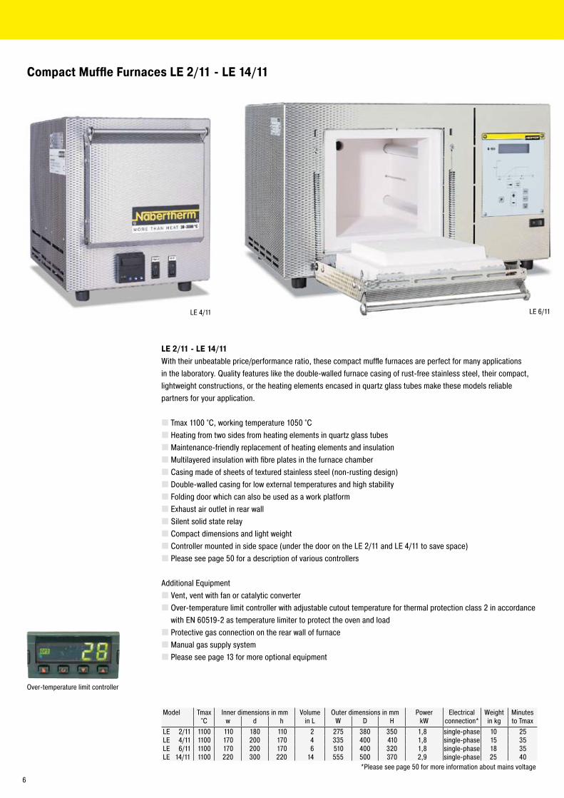
Compact Muffle Furnaces LE 2/11 - LE 14/11
LE 2/11 - LE 14/11With their unbeatable price/performance ratio, these compact muffle furnaces are perfect for many applications in the laboratory. Quality features like the double-walled furnace casing of rust-free stainless steel, their compact, lightweight constructions, or the heating elements encased in quartz glass tubes make these models reliable partners for your application.
Tmax 1100 °C, working temperature 1050 °CHeating from two sides from heating elements in quartz glass tubesMaintenance-friendly replacement of heating elements and insulationMultilayered insulation with fibre plates in the furnace chamberCasing made of sheets of textured stainless steel (non-rusting design)Double-walled casing for low external temperatures and high stabilityFolding door which can also be used as a work platformExhaust air outlet in rear wallSilent solid state relayCompact dimensions and light weightController mounted in side space (under the door on the LE �/11 and LE 4/11 to save space)Please see page 50 for a description of various controllers
Additional EquipmentVent, vent with fan or catalytic converterOver-temperature limit controller with adjustable cutout temperature for thermal protection class � in accordance with EN 60519-� as temperature limiter to protect the oven and loadProtective gas connection on the rear wall of furnaceManual gas supply systemPlease see page 13 for more optional equipment
Model Tmax Inner dimensions in mm Volume Outer dimensions in mm Power Electrical Weight Minutes °C w d h in L W D H kW connection* in kg to Tmax
LE �/11 1100 110 180 110 � �75 380 350 1,8 single-phase 10 �5LE 4/11 1100 170 �00 170 4 335 400 410 1,8 single-phase 15 35LE 6/11 1100 170 �00 170 6 510 400 3�0 1,8 single-phase 18 35LE 14/11 1100 ��0 300 ��0 14 555 500 370 �,9 single-phase �5 40
*Please see page 50 for more information about mains voltage
Over-temperature limit controller
6
LE 6/11
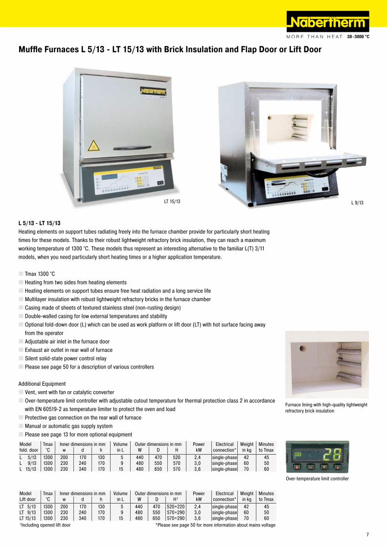
LT 15/13 L 9/13
Muffle Furnaces L 5/13 - LT 15/13 with Brick Insulation and Flap Door or Lift Door
L 5/13 - LT 15/13Heating elements on support tubes radiating freely into the furnace chamber provide for particularly short heating times for these models. Thanks to their robust lightweight refractory brick insulation, they can reach a maximum working temperature of 1300 °C. These models thus represent an interesting alternative to the familiar L(T) 3/11 models, when you need particularly short heating times or a higher application temperature.
Tmax 1300 °CHeating from two sides from heating elementsHeating elements on support tubes ensure free heat radiation and a long service lifeMultilayer insulation with robust lightweight refractory bricks in the furnace chamberCasing made of sheets of textured stainless steel (non-rusting design)Double-walled casing for low external temperatures and stabilityOptional fold-down door (L) which can be used as work platform or lift door (LT) with hot surface facing away from the operatorAdjustable air inlet in the furnace doorExhaust air outlet in rear wall of furnaceSilent solid-state power control relayPlease see page 50 for a description of various controllers
Additional EquipmentVent, vent with fan or catalytic converterOver-temperature limit controller with adjustable cutout temperature for thermal protection class � in accordance with EN 60519-� as temperature limiter to protect the oven and loadProtective gas connection on the rear wall of furnaceManual or automatic gas supply systemPlease see page 13 for more optional equipment
Furnace lining with high-quality lightweight refractory brick insulation
Over-temperature limit controller
Model Tmax Inner dimensions in mm Volume Outer dimensions in mm Power Electrical Weight Minutes fold. door °C w d h in L W D H kW connection* in kg to TmaxL 5/13 1300 �00 170 130 5 440 470 5�0 �,4 single-phase 4� 45L 9/13 1300 �30 �40 170 9 480 550 570 3,0 single-phase 60 50L 15/13 1300 �30 340 170 15 480 650 570 3,6 single-phase 70 60
Model Tmax Inner dimensions in mm Volume Outer dimensions in mm Power Electrical Weight Minutes Lift door °C w d h in L W D H¹ kW connection* in kg to TmaxLT 5/13 1300 �00 170 130 5 440 470 5�0+��0 �,4 single-phase 4� 45LT 9/13 1300 �30 �40 170 9 480 550 570+�90 3,0 single-phase 60 50LT 15/13 1300 �30 340 170 15 480 650 570+�90 3,6 single-phase 70 60¹Including opened lift door *Please see page 50 for more information about mains voltage
7
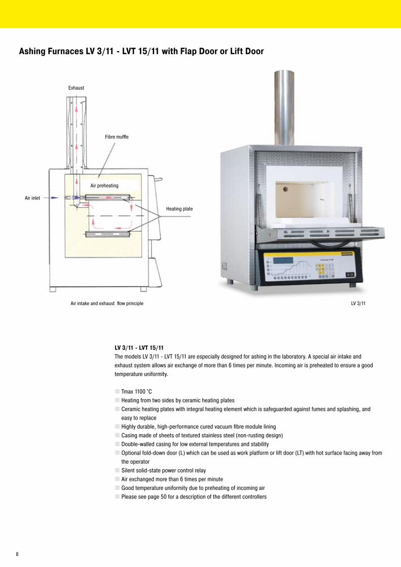
LV 3/11
Ashing Furnaces LV 3/11 - LVT 15/11 with Flap Door or Lift Door
LV 3/11 - LVT 15/11The models LV 3/11 - LVT 15/11 are especially designed for ashing in the laboratory. A special air intake and exhaust system allows air exchange of more than 6 times per minute. Incoming air is preheated to ensure a good temperature uniformity.
Tmax 1100 °CHeating from two sides by ceramic heating platesCeramic heating plates with integral heating element which is safeguarded against fumes and splashing, and easy to replaceHighly durable, high-performance cured vacuum fibre module liningCasing made of sheets of textured stainless steel (non-rusting design)Double-walled casing for low external temperatures and stabilityOptional fold-down door (L) which can be used as work platform or lift door (LT) with hot surface facing away from the operatorSilent solid-state power control relayAir exchanged more than 6 times per minuteGood temperature uniformity due to preheating of incoming airPlease see page 50 for a description of the different controllers
Air inlet
Fibre muffle
Heating plate
Exhaust
Air intake and exhaust flow principle
Air preheating
8
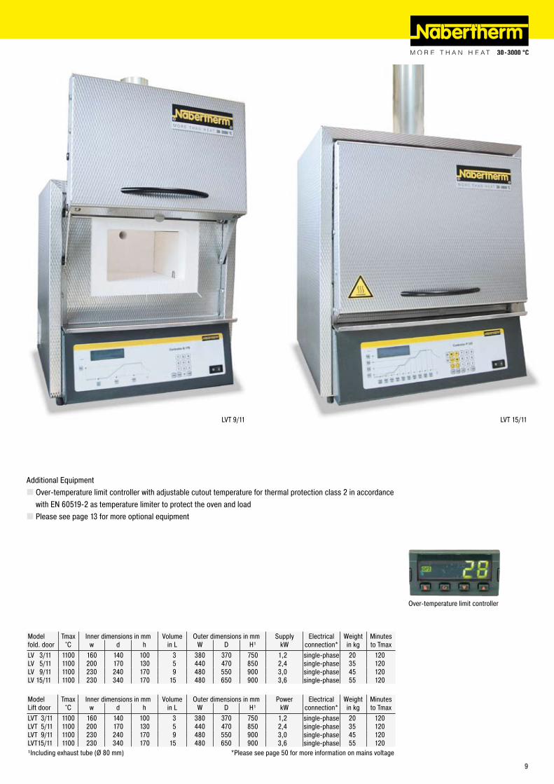
LVT 9/11 LVT 15/11
Additional EquipmentOver-temperature limit controller with adjustable cutout temperature for thermal protection class � in accordance with EN 60519-� as temperature limiter to protect the oven and loadPlease see page 13 for more optional equipment
Model Tmax Inner dimensions in mm Volume Outer dimensions in mm Supply Electrical Weight Minutes fold. door °C w d h in L W D H¹ kW connection* in kg to TmaxLV 3/11 1100 160 140 100 3 380 370 750 1,� single-phase �0 1�0LV 5/11 1100 �00 170 130 5 440 470 850 �,4 single-phase 35 1�0LV 9/11 1100 �30 �40 170 9 480 550 900 3,0 single-phase 45 1�0LV 15/11 1100 �30 340 170 15 480 650 900 3,6 single-phase 55 1�0
Model Tmax Inner dimensions in mm Volume Outer dimensions in mm Power Electrical Weight Minutes Lift door °C w d h in L W D H¹ kW connection* in kg to TmaxLVT 3/11 1100 160 140 100 3 380 370 750 1,� single-phase �0 1�0LVT 5/11 1100 �00 170 130 5 440 470 850 �,4 single-phase 35 1�0LVT 9/11 1100 �30 �40 170 9 480 550 900 3,0 single-phase 45 1�0LVT15/11 1100 �30 340 170 15 480 650 900 3,6 single-phase 55 1�0¹Including exhaust tube (Ø 80 mm) *Please see page 50 for more information on mains voltage
Over-temperature limit controller
9
L 9/11/SKM
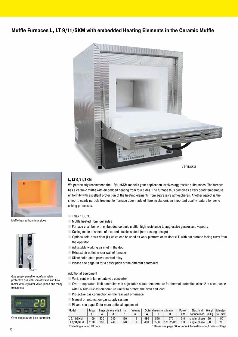
Muffle Furnaces L, LT 9/11/SKM with embedded Heating Elements in the Ceramic Muffle
L, LT 9/11/SKMWe particularly recommend the L 9/11/SKM model if your application involves aggressive substances. The furnace has a ceramic muffle with embedded heating from four sides. The furnace thus combines a very good temperature uniformity with excellent protection of the heating elements from aggressive atmospheres. Another aspect is the smooth, nearly particle free muffle (furnace door made of fibre insulation), an important quality feature for some ashing processes.
Tmax 1100 °CMuffle heated from four sidesFurnace chamber with embedded ceramic muffle, high resistance to aggressive gasses and vapoursCasing made of sheets of textured stainless steel (non-rusting design)Optional fold-down door (L) which can be used as work platform or lift door (LT) with hot surface facing away from the operatorAdjustable working air inlet in the doorExhaust air outlet in rear wall of furnaceSilent solid-state power control relayPlease see page 50 for a description of the different controllers
Additional EquipmentVent, vent with fan or catalytic converterOver-temperature limit controller with adjustable cutout temperature for thermal protection class � in accordance with EN 60519-� as temperature limiter to protect the oven and loadProtective gas connection on the rear wall of furnaceManual or automation gas supply systemPlease see page 13 for more optional equipment
Over-temperature limit controller
Muffle heated from four sides
Model Tmax Inner dimensions in mm Volume Outer dimensions in mm Power Electrical Weight Minutes°C w d h in L W D H kW connection* in kg to Tmax
L 9/11/SKM 1100 �30 �40 170 9 480 550 570 3,0 single-phase 50 90LT 9/11/SKM 1100 �30 �40 170 9 480 550 570+�90¹ 3,0 single-phase 50 90¹Including opened lift door *Please see page 50 for more information about mains voltage
Gas supply panel for nonflammable protective gas with shutoff valve and flow meter with regulator valve, piped and ready to connect
10
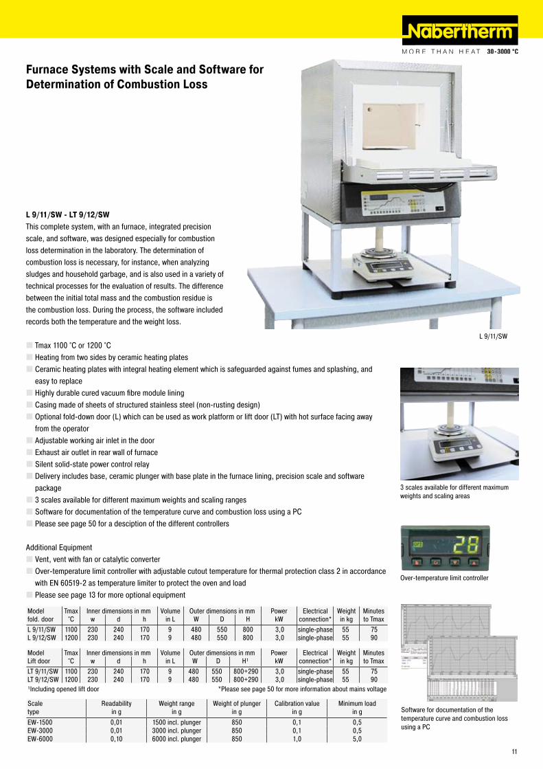
L 9/11/SW
Furnace Systems with Scale and Software forDetermination of Combustion Loss
Software for documentation of the temperature curve and combustion loss using a PC
L 9/11/SW - LT 9/12/SWThis complete system, with an furnace, integrated precision scale, and software, was designed especially for combustion loss determination in the laboratory. The determination of combustion loss is necessary, for instance, when analyzing sludges and household garbage, and is also used in a variety of technical processes for the evaluation of results. The difference between the initial total mass and the combustion residue is the combustion loss. During the process, the software included records both the temperature and the weight loss.
Tmax 1100 °C or 1�00 °CHeating from two sides by ceramic heating platesCeramic heating plates with integral heating element which is safeguarded against fumes and splashing, and easy to replaceHighly durable cured vacuum fibre module liningCasing made of sheets of structured stainless steel (non-rusting design)Optional fold-down door (L) which can be used as work platform or lift door (LT) with hot surface facing away from the operatorAdjustable working air inlet in the doorExhaust air outlet in rear wall of furnaceSilent solid-state power control relayDelivery includes base, ceramic plunger with base plate in the furnace lining, precision scale and software package3 scales available for different maximum weights and scaling rangesSoftware for documentation of the temperature curve and combustion loss using a PCPlease see page 50 for a desciption of the different controllers
Additional EquipmentVent, vent with fan or catalytic converterOver-temperature limit controller with adjustable cutout temperature for thermal protection class � in accordance with EN 60519-� as temperature limiter to protect the oven and loadPlease see page 13 for more optional equipment
Model Tmax Inner dimensions in mm Volume Outer dimensions in mm Power Electrical Weight Minutesfold. door °C w d h in L W D H kW connection* in kg to TmaxL 9/11/SW 1100 �30 �40 170 9 480 550 800 3,0 single-phase 55 75L 9/1�/SW 1�00 �30 �40 170 9 480 550 800 3,0 single-phase 55 90
Scale Readability Weight range Weight of plunger Calibration value Minimum loadtype in g in g in g in g in gEW-1500 0,01 1500 incl. plunger 850 0,1 0,5EW-3000 0,01 3000 incl. plunger 850 0,1 0,5EW-6000 0,10 6000 incl. plunger 850 1,0 5,0
Model Tmax Inner dimensions in mm Volume Outer dimensions in mm Power Electrical Weight Minutes Lift door °C w d h in L W D H¹ kW connection* in kg to TmaxLT 9/11/SW 1100 �30 �40 170 9 480 550 800+�90 3,0 single-phase 55 75LT 9/1�/SW 1�00 �30 �40 170 9 480 550 800+�90 3,0 single-phase 55 90¹Including opened lift door *Please see page 50 for more information about mains voltage
Over-temperature limit controller
3 scales available for different maximum weights and scaling areas
11
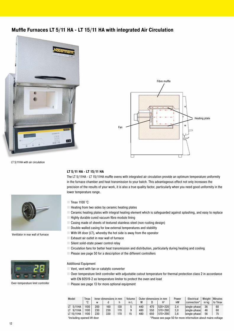
Muffle Furnaces LT 5/11 HA - LT 15/11 HA with integrated Air Circulation
LT 5/11 HA - LT 15/11 HAThe LT 5/11HA - LT 15/11HA muffle ovens with integrated air circulation provide an optimum temperature uniformity in the furnace chamber and heat transmission to your batch. This advantageous effect not only increases the precision of the results of your work, it is also a true quality factor, particularly when you need good uniformity in the lower temperature range.
Tmax 1100 °CHeating from two sides by ceramic heating platesCeramic heating plates with integral heating element which is safeguarded against splashing, and easy to replaceHighly durable cured vacuum fibre module liningCasing made of sheets of textured stainless steel (non-rusting design)Double-walled casing for low external temperatures and stabilityWith lift door (LT), whereby the hot side is away from the operatorExhaust air outlet in rear wall of furnaceSilent solid-state power control relayCirculation fans for better heat transmission and distribution, particularly during heating and coolingPlease see page 50 for a description of the different controllers
Additional EquipmentVent, vent with fan or catalytic converterOver-temperature limit controller with adjustable cutout temperature for thermal protection class � in accordance with EN 60519-� as temperature limiter to protect the oven and loadPlease see page 13 for more optional equipment
Ventilator in rear wall of furnace
Fan
Fibre muffle
Heating plate
LT 5/11HA with air circulation
Over-temperature limit controller
Model Tmax Inner dimensions in mm Volume Outer dimensions in mm Power Electrical Weight Minutes°C w d h in L W D H¹ kW connection* in kg to Tmax
LT 5/11HA 1100 �00 160 130 5 440 470 5�0+��0 �,4 single-phase 36 60LT 9/11HA 1100 �30 �30 170 9 480 550 570+�90 3,0 single-phase 46 60LT 15/11HA 1100 �30 330 170 15 480 650 570+�90 3,6 single-phase 56 75¹Including opened lift door *Please see page 50 for more information about mains voltage
1�
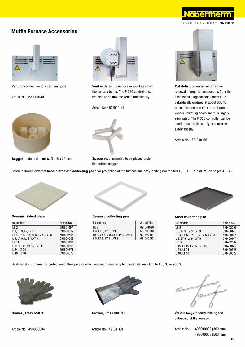
Muffle Furnace Accessories
Vent for connection to an exhaust pipe.
Article No.: 631000140
Vent with fan, to remove exhaust gas from the furnace better. The P 330 controller can be used to control the vent automatically.
Article No.: 631000141
Catalytic converter with fan for removal of organic components from the exhaust air. Organic components are catalytically oxidized at about 600 °C, broken into carbon dioxide and water vapour. Irritating odors are thus largely eliminated. The P 330 controller can be used to switch the catalytic converter automatically.
Article No.: 631000166
Ceramic ribbed plate Ceramic collecting pan Steel collecting pan
Select between different base plates and collecting pans for protection of the furnace and easy loading (for models L, LT, LE, LV and LVT on pages 4 - 1�).
Heat-resistant gloves for protection of the operator when loading or removing hot materials, resistant to 600 °C or 900 °C.
Gloves, Tmax 650 °C.
Article No.: 493000004
Gloves, Tmax 900 °C.
Article No.: 491041101
Various tongs for easy loading and unloading of the furnace.
Article No.: 49300000� (300 mm) 493000003 (500 mm)
for models Articel No.LE � 691601097L 3, LT 3, LV, LVT 3 691600507LE 4, LE 6, L 5, LT 5, LV 5, LVT 5 691600508L 9, LT 9, LV 9, LVT 9 691600509LE 14 691601098L 15, LT 15, LV 15, LVT 15 691600506L �4, LT �4 691600874L 40, LT 40 691600875
for models Articel No.LE � 691601099L 3, LT 3, LV 3, LVT 3 691600510LE 4, LE 6, L 5, LT 5, LV 5, LVT 5 691600511L 9, LT 9, LV 9, LVT 9 69160051�
for models Articel No.LE � 69140�096L 3, LT 3, LV 3, LVT 3 691400145LE 4, LE 6, L 5, LT 5, LV 5, LVT 5 691400146L 9, LT 9, LV 9, LVT 9 691400147LE 14 69140�097L 15, LT 15, LV 15, LVT 15 691400149L �4, LT �4 6914006�6L 40, LT 40 6914006�7
Saggar made of ceramics, Ø 115 x 35 mm Spacer recommended to be placed under the bottom saggar
13
N 41/H
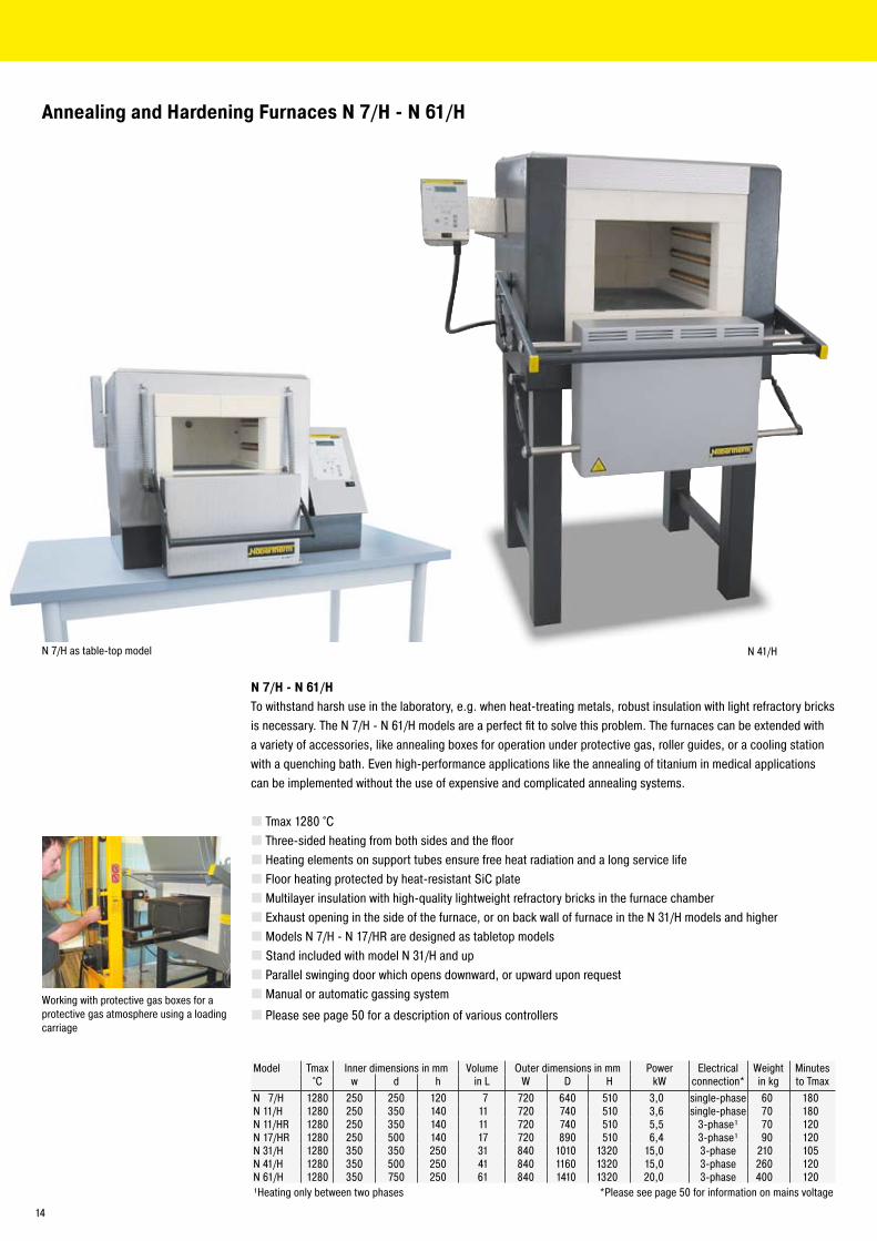
Annealing and Hardening Furnaces N 7/H - N 61/H
N 7/H as table-top model
N 7/H - N 61/HTo withstand harsh use in the laboratory, e.g. when heat-treating metals, robust insulation with light refractory bricks is necessary. The N 7/H - N 61/H models are a perfect fit to solve this problem. The furnaces can be extended with a variety of accessories, like annealing boxes for operation under protective gas, roller guides, or a cooling station with a quenching bath. Even high-performance applications like the annealing of titanium in medical applications can be implemented without the use of expensive and complicated annealing systems.
Tmax 1�80 °CThree-sided heating from both sides and the floorHeating elements on support tubes ensure free heat radiation and a long service lifeFloor heating protected by heat-resistant SiC plateMultilayer insulation with high-quality lightweight refractory bricks in the furnace chamberExhaust opening in the side of the furnace, or on back wall of furnace in the N 31/H models and higherModels N 7/H - N 17/HR are designed as tabletop modelsStand included with model N 31/H and upParallel swinging door which opens downward, or upward upon requestManual or automatic gassing system
Please see page 50 for a description of various controllers
Model Tmax Inner dimensions in mm Volume Outer dimensions in mm Power Electrical Weight Minutes°C w d h in L W D H kW connection* in kg to Tmax
N 7/H 1�80 �50 �50 1�0 7 7�0 640 510 3,0 single-phase 60 180N 11/H 1�80 �50 350 140 11 7�0 740 510 3,6 single-phase 70 180N 11/HR 1�80 �50 350 140 11 7�0 740 510 5,5 3-phase¹ 70 1�0N 17/HR 1�80 �50 500 140 17 7�0 890 510 6,4 3-phase¹ 90 1�0N 31/H 1�80 350 350 �50 31 840 1010 13�0 15,0 3-phase �10 105N 41/H 1�80 350 500 �50 41 840 1160 13�0 15,0 3-phase �60 1�0N 61/H 1�80 350 750 �50 61 840 1410 13�0 �0,0 3-phase 400 1�0¹Heating only between two phases *Please see page 50 for information on mains voltage
Working with protective gas boxes for a protective gas atmosphere using a loading carriage
14
www.nabertherm.com
Madein Germany
Heat Treatment Metals, Plastics and Surface Finishing
Furnaces and Systems for Tempering AnnealingHardeningQuenchingSolution AnnealingAgeingForgingPreheatingDryingCuring
www.nabertherm.com
MadeinGermany
FurnacesProtective Gas BoxesHardening SystemsQuenching BathsCharging PlatesTongsGlovesCharging BasketsOther Accessories
Heat TreatmentAnnealing, Hardening, Brazing, Forging, Nitriding
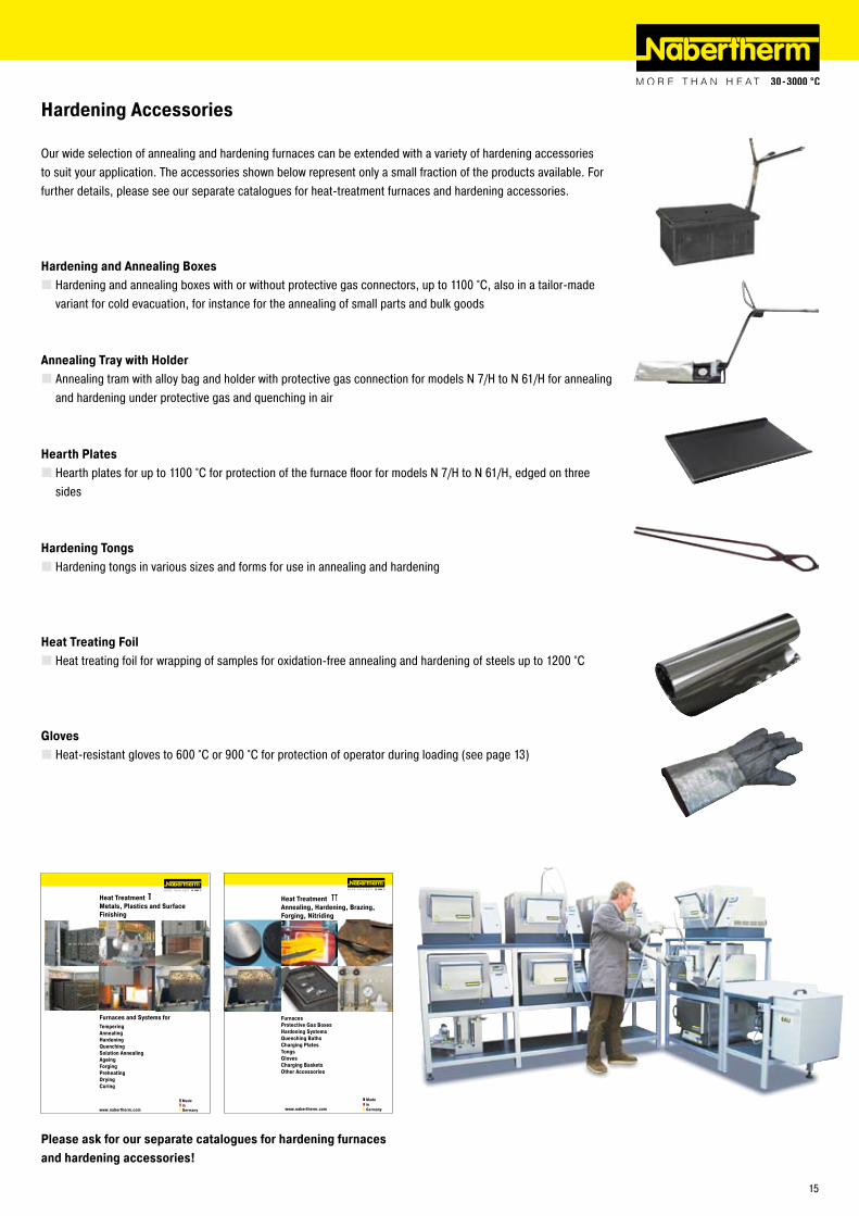
Hardening Accessories
Our wide selection of annealing and hardening furnaces can be extended with a variety of hardening accessories to suit your application. The accessories shown below represent only a small fraction of the products available. For further details, please see our separate catalogues for heat-treatment furnaces and hardening accessories.
Hardening and Annealing BoxesHardening and annealing boxes with or without protective gas connectors, up to 1100 °C, also in a tailor-made variant for cold evacuation, for instance for the annealing of small parts and bulk goods
Annealing Tray with HolderAnnealing tram with alloy bag and holder with protective gas connection for models N 7/H to N 61/H for annealing and hardening under protective gas and quenching in air
Hearth PlatesHearth plates for up to 1100 °C for protection of the furnace floor for models N 7/H to N 61/H, edged on three sides
Hardening TongsHardening tongs in various sizes and forms for use in annealing and hardening
Heat Treating FoilHeat treating foil for wrapping of samples for oxidation-free annealing and hardening of steels up to 1�00 °C
GlovesHeat-resistant gloves to 600 °C or 900 °C for protection of operator during loading (see page 13)
Please ask for our separate catalogues for hardening furnaces and hardening accessories!
15
°C
1300
1200+ 2K+ 2K
+ 2K
+ 3K
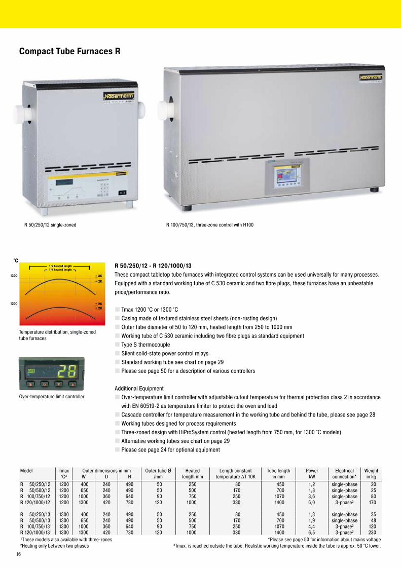
Compact Tube Furnaces R
R 50/250/12 - R 120/1000/13These compact tabletop tube furnaces with integrated control systems can be used universally for many processes. Equipped with a standard working tube of C 530 ceramic and two fibre plugs, these furnaces have an unbeatable price/performance ratio.
Tmax 1�00 °C or 1300 °CCasing made of textured stainless steel sheets (non-rusting design)Outer tube diameter of 50 to 1�0 mm, heated length from �50 to 1000 mmWorking tube of C 530 ceramic including two fibre plugs as standard equipmentType S thermocoupleSilent solid-state power control relaysStandard working tube see chart on page �9Please see page 50 for a description of various controllers
Additional EquipmentOver-temperature limit controller with adjustable cutout temperature for thermal protection class � in accordance with EN 60519-� as temperature limiter to protect the oven and loadCascade controller for temperature measurement in the working tube and behind the tube, please see page �8Working tubes designed for process requirementsThree-zoned design with HiProSystem control (heated length from 750 mm, for 1300 °C models)Alternative working tubes see chart on page �9Please see page �4 for optional equipment
Temperature distribution, single-zoned tube furnaces
1/2 heated length1/4 heated length
R 100/750/13, three-zone control with H100R 50/�50/1� single-zoned
Model Tmax Outer dimensions in mm Outer tube Ø Heated Length constant Tube length Power Electrical Weight°C³ W D H /mm length mm temperature ΔT 10K in mm kW connection* in kg
R 50/�50/1� 1�00 400 �40 490 50 �50 80 450 1,� single-phase �0R 50/500/1� 1�00 650 �40 490 50 500 170 700 1,8 single-phase �5R 100/750/1� 1�00 1000 360 640 90 750 �50 1070 3,6 single-phase 80R 1�0/1000/1� 1�00 1300 4�0 730 1�0 1000 330 1400 6,0 3-phase² 170
R 50/�50/13 1300 400 �40 490 50 �50 80 450 1,3 single-phase 35R 50/500/13 1300 650 �40 490 50 500 170 700 1,9 single-phase 48R 100/750/13¹ 1300 1000 360 640 90 750 �50 1070 4,4 3-phase² 1�0R 1�0/1000/13¹ 1300 1300 4�0 730 1�0 1000 330 1400 6,5 3-phase² �30¹These models also available with three-zones *Please see page 50 for information about mains voltage²Heating only between two phases ³Tmax. is reached outside the tube. Realistic working temperature inside the tube is approx. 50 °C lower.
Over-temperature limit controller
16
RT 50-250/11
RT 50-250/13
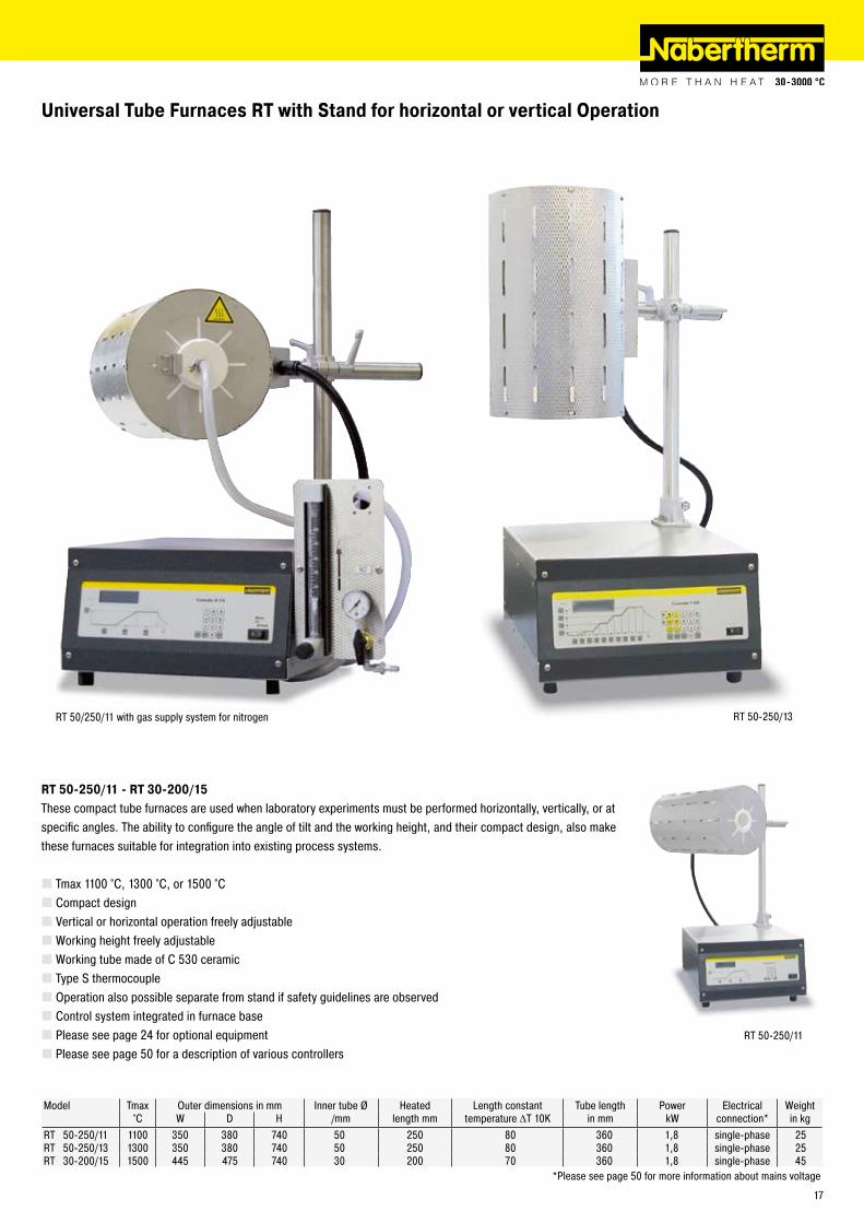
Universal Tube Furnaces RT with Stand for horizontal or vertical Operation
RT 50-250/11 - RT 30-200/15These compact tube furnaces are used when laboratory experiments must be performed horizontally, vertically, or at specific angles. The ability to configure the angle of tilt and the working height, and their compact design, also make these furnaces suitable for integration into existing process systems.
Tmax 1100 °C, 1300 °C, or 1500 °CCompact designVertical or horizontal operation freely adjustableWorking height freely adjustableWorking tube made of C 530 ceramicType S thermocoupleOperation also possible separate from stand if safety guidelines are observedControl system integrated in furnace basePlease see page �4 for optional equipmentPlease see page 50 for a description of various controllers
Model Tmax Outer dimensions in mm Inner tube Ø Heated Length constant Tube length Power Electrical Weight°C W D H /mm length mm temperature ΔT 10K in mm kW connection* in kg
RT 50-�50/11 1100 350 380 740 50 �50 80 360 1,8 single-phase �5RT 50-�50/13 1300 350 380 740 50 �50 80 360 1,8 single-phase �5RT 30-�00/15 1500 445 475 740 30 �00 70 360 1,8 single-phase 45
*Please see page 50 for more information about mains voltage
RT 50/�50/11 with gas supply system for nitrogen
17
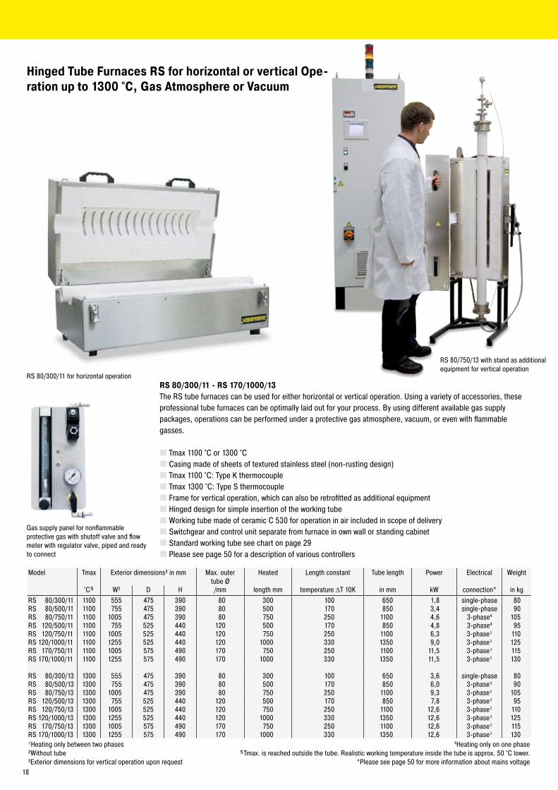
Hinged Tube Furnaces RS for horizontal or vertical Ope-ration up to 1300 °C, Gas Atmosphere or Vacuum
RS 80/300/11 for horizontal operation
RS 80/750/13 with stand as additional equipment for vertical operation
RS 80/300/11 - RS 170/1000/13The RS tube furnaces can be used for either horizontal or vertical operation. Using a variety of accessories, these professional tube furnaces can be optimally laid out for your process. By using different available gas supply packages, operations can be performed under a protective gas atmosphere, vacuum, or even with flammable gasses.
Tmax 1100 °C or 1300 °CCasing made of sheets of textured stainless steel (non-rusting design)Tmax 1100 °C: Type K thermocoupleTmax 1300 °C: Type S thermocoupleFrame for vertical operation, which can also be retrofitted as additional equipmentHinged design for simple insertion of the working tubeWorking tube made of ceramic C 530 for operation in air included in scope of deliverySwitchgear and control unit separate from furnace in own wall or standing cabinetStandard working tube see chart on page �9Please see page 50 for a description of various controllers
Model Tmax Exterior dimensions³ in mm Max. outer tube Ø
Heated Length constant Tube length Power Electrical Weight
°C� W² D H /mm length mm temperature ΔT 10K in mm kW connection* in kgRS 80/300/11 1100 555 475 390 80 300 100 650 1,8 single-phase 80RS 80/500/11 1100 755 475 390 80 500 170 850 3,4 single-phase 90RS 80/750/11 1100 1005 475 390 80 750 �50 1100 4,6 3-phase4 105RS 1�0/500/11 1100 755 5�5 440 1�0 500 170 850 4,8 3-phase4 95RS 1�0/750/11 1100 1005 5�5 440 1�0 750 �50 1100 6,3 3-phase¹ 110RS 1�0/1000/11 1100 1�55 5�5 440 1�0 1000 330 1350 9,0 3-phase¹ 1�5RS 170/750/11 1100 1005 575 490 170 750 �50 1100 11,5 3-phase¹ 115RS 170/1000/11 1100 1�55 575 490 170 1000 330 1350 11,5 3-phase¹ 130
RS 80/300/13 1300 555 475 390 80 300 100 650 3,6 single-phase 80RS 80/500/13 1300 755 475 390 80 500 170 850 6,0 3-phase¹ 90RS 80/750/13 1300 1005 475 390 80 750 �50 1100 9,3 3-phase¹ 105RS 1�0/500/13 1300 755 5�5 440 1�0 500 170 850 7,8 3-phase¹ 95RS 1�0/750/13 1300 1005 5�5 440 1�0 750 �50 1100 1�,6 3-phase¹ 110RS 1�0/1000/13 1300 1�55 5�5 440 1�0 1000 330 1350 1�,6 3-phase¹ 1�5RS 170/750/13 1300 1005 575 490 170 750 �50 1100 1�,6 3-phase¹ 115RS 170/1000/13 1300 1�55 575 490 170 1000 330 1350 1�,6 3-phase¹ 130¹Heating only between two phases 4Heating only on one phase²Without tube �Tmax. is reached outside the tube. Realistic working temperature inside the tube is approx. 50 °C lower.³Exterior dimensions for vertical operation upon request *Please see page 50 for more information about mains voltage
Gas supply panel for nonflammable protective gas with shutoff valve and flow meter with regulator valve, piped and ready to connect
18
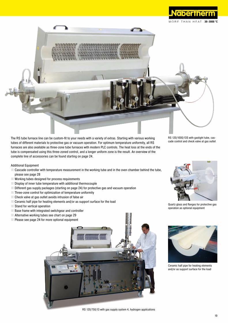
RS 1�0/1000/13S with gastight tube, cas-cade control and check valve at gas outlet
Quartz glass and flanges for protective gas operation as optional equipment
The RS tube furnace line can be custom-fit to your needs with a variety of extras. Starting with various working tubes of different materials to protective gas or vacuum operation. For optimum temperature uniformity, all RS furnaces are also available as three-zone tube furnaces with modern PLC controls. The heat loss at the ends of the tube is compensated using this three-zoned control, and a longer uniform zone is the result. An overview of the complete line of accessories can be found starting on page �4.
Additional EquipmentCascade controller with temperature measurement in the working tube and in the oven chamber behind the tube, please see page �8Working tubes designed for process requirementsDisplay of inner tube temperature with additional thermocoupleDifferent gas supply packages (starting on page �4) for protective gas and vacuum operationThree-zone control for optimization of temperature uniformityCheck valve at gas outlet avoids intrusion of false airCeramic half pipe for heating elements and/or as support surface for the loadStand for vertical operationBase frame with integrated switchgear and controllerAlternative working tubes see chart on page �9Please see page �4 for more optional equipment
Ceramic half pipe for heating elements and/or as support surface for the load
RS 1�0/750/13 with gas supply system 4, hydrogen applications
19
L
D
Ll
dD
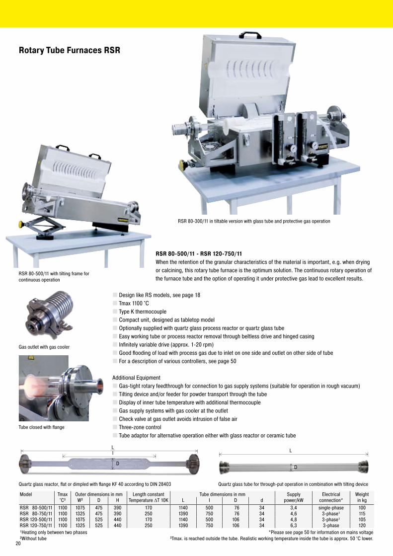
Rotary Tube Furnaces RSR
RSR 80-500/11 - RSR 120-750/11When the retention of the granular characteristics of the material is important, e.g. when drying or calcining, this rotary tube furnace is the optimum solution. The continuous rotary operation of
the furnace tube and the option of operating it under protective gas lead to excellent results.
Design like RS models, see page 18Tmax 1100 °CType K thermocoupleCompact unit, designed as tabletop modelOptionally supplied with quartz glass process reactor or quartz glass tubeEasy working tube or process reactor removal through beltless drive and hinged casingInfinitely variable drive (approx. 1-�0 rpm)Good flooding of load with process gas due to inlet on one side and outlet on other side of tubeFor a description of various controllers, see page 50
Additional EquipmentGas-tight rotary feedthrough for connection to gas supply systems (suitable for operation in rough vacuum)Tilting device and/or feeder for powder transport through the tubeDisplay of inner tube temperature with additional thermocoupleGas supply systems with gas cooler at the outletCheck valve at gas outlet avoids intrusion of false airThree-zone controlTube adaptor for alternative operation either with glass reactor or ceramic tube
Gas outlet with gas cooler
Quartz glass tube for through-put operation in combination with tilting deviceQuartz glass reactor, flat or dimpled with flange KF 40 according to DIN �8403
Model Tmax Outer dimensions in mm Length constant Tube dimensions in mm Supply Electrical Weight°C³ W² D H Temperature ΔT 10K L I D d power/kW connection* in kg
RSR 80-500/11 1100 1075 475 390 170 1140 500 76 34 3,4 single-phase 100RSR 80-750/11 1100 13�5 475 390 �50 1390 750 76 34 4,6 3-phase¹ 115RSR 1�0-500/11 1100 1075 5�5 440 170 1140 500 106 34 4,8 3-phase¹ 105RSR 1�0-750/11 1100 13�5 5�5 440 �50 1390 750 106 34 6,3 3-phase 1�0¹Heating only between two phases *Please see page 50 for information on mains voltage²Without tube ³Tmax. is reached outside the tube. Realistic working temperature inside the tube is approx. 50 °C lower.
RSR 80-300/11 in tiltable version with glass tube and protective gas operation
RSR 80-500/11 with tilting frame for continuous operation
Tube closed with flange
�0
RHTC 80-�30
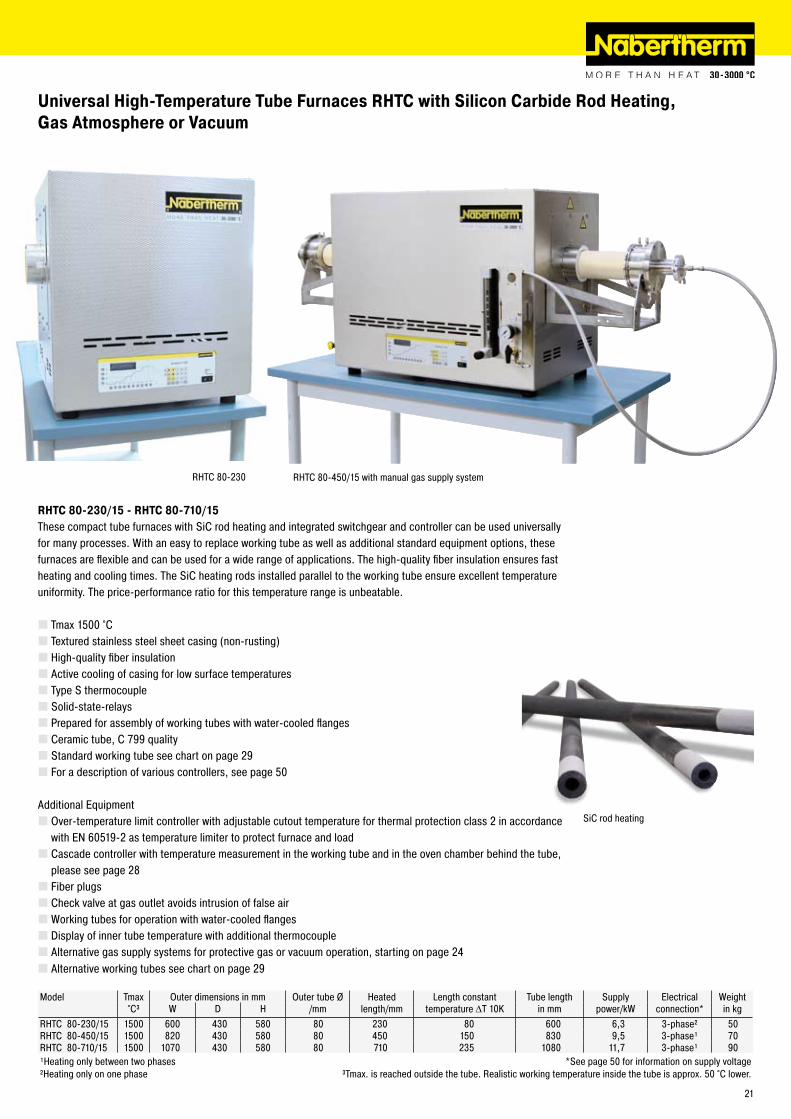
Universal High-Temperature Tube Furnaces RHTC with Silicon Carbide Rod Heating,Gas Atmosphere or Vacuum
RHTC 80-230/15 - RHTC 80-710/15These compact tube furnaces with SiC rod heating and integrated switchgear and controller can be used universally for many processes. With an easy to replace working tube as well as additional standard equipment options, these furnaces are flexible and can be used for a wide range of applications. The high-quality fiber insulation ensures fast heating and cooling times. The SiC heating rods installed parallel to the working tube ensure excellent temperature uniformity. The price-performance ratio for this temperature range is unbeatable.
Tmax 1500 °CTextured stainless steel sheet casing (non-rusting)High-quality fiber insulationActive cooling of casing for low surface temperaturesType S thermocoupleSolid-state-relaysPrepared for assembly of working tubes with water-cooled flangesCeramic tube, C 799 qualityStandard working tube see chart on page �9For a description of various controllers, see page 50
Additional EquipmentOver-temperature limit controller with adjustable cutout temperature for thermal protection class � in accordance with EN 60519-� as temperature limiter to protect furnace and loadCascade controller with temperature measurement in the working tube and in the oven chamber behind the tube, please see page �8Fiber plugsCheck valve at gas outlet avoids intrusion of false airWorking tubes for operation with water-cooled flangesDisplay of inner tube temperature with additional thermocoupleAlternative gas supply systems for protective gas or vacuum operation, starting on page �4Alternative working tubes see chart on page �9
SiC rod heating
Model Tmax Outer dimensions in mm Outer tube Ø Heated Length constant Tube length Supply Electrical Weight°C³ W D H /mm length/mm temperature ΔT 10K in mm power/kW connection* in kg
RHTC 80-�30/15 1500 600 430 580 80 �30 80 600 6,3 3-phase² 50RHTC 80-450/15 1500 8�0 430 580 80 450 150 830 9,5 3-phase¹ 70RHTC 80-710/15 1500 1070 430 580 80 710 �35 1080 11,7 3-phase¹ 90¹Heating only between two phases *See page 50 for information on supply voltage²Heating only on one phase ³Tmax. is reached outside the tube. Realistic working temperature inside the tube is approx. 50 °C lower.
RHTC 80-450/15 with manual gas supply system
�1
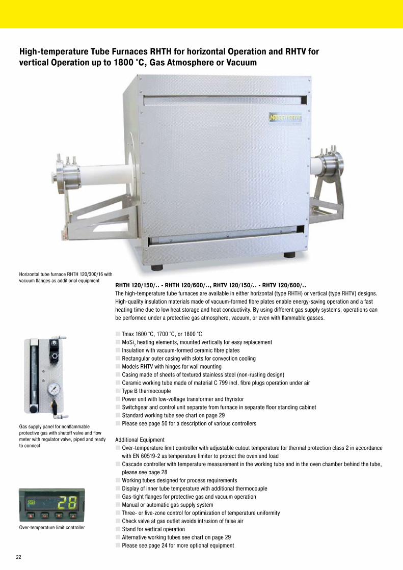
High-temperature Tube Furnaces RHTH for horizontal Operation and RHTV forvertical Operation up to 1800 °C, Gas Atmosphere or Vacuum
RHTH 120/150/.. - RHTH 120/600/.., RHTV 120/150/.. - RHTV 120/600/..The high-temperature tube furnaces are available in either horizontal (type RHTH) or vertical (type RHTV) designs. High-quality insulation materials made of vacuum-formed fibre plates enable energy-saving operation and a fast heating time due to low heat storage and heat conductivity. By using different gas supply systems, operations can be performed under a protective gas atmosphere, vacuum, or even with flammable gasses.
Tmax 1600 °C, 1700 °C, or 1800 °CMoSi� heating elements, mounted vertically for easy replacementInsulation with vacuum-formed ceramic fibre platesRectangular outer casing with slots for convection coolingModels RHTV with hinges for wall mountingCasing made of sheets of textured stainless steel (non-rusting design)Ceramic working tube made of material C 799 incl. fibre plugs operation under airType B thermocouplePower unit with low-voltage transformer and thyristorSwitchgear and control unit separate from furnace in separate floor standing cabinetStandard working tube see chart on page �9Please see page 50 for a description of various controllers
Additional EquipmentOver-temperature limit controller with adjustable cutout temperature for thermal protection class � in accordance with EN 60519-� as temperature limiter to protect the oven and loadCascade controller with temperature measurement in the working tube and in the oven chamber behind the tube, please see page �8Working tubes designed for process requirementsDisplay of inner tube temperature with additional thermocoupleGas-tight flanges for protective gas and vacuum operationManual or automatic gas supply systemThree- or five-zone control for optimization of temperature uniformityCheck valve at gas outlet avoids intrusion of false airStand for vertical operationAlternative working tubes see chart on page �9Please see page �4 for more optional equipment
Horizontal tube furnace RHTH 1�0/300/16 with vacuum flanges as additional equipment
Over-temperature limit controller
Gas supply panel for nonflammable protective gas with shutoff valve and flow meter with regulator valve, piped and ready to connect
��
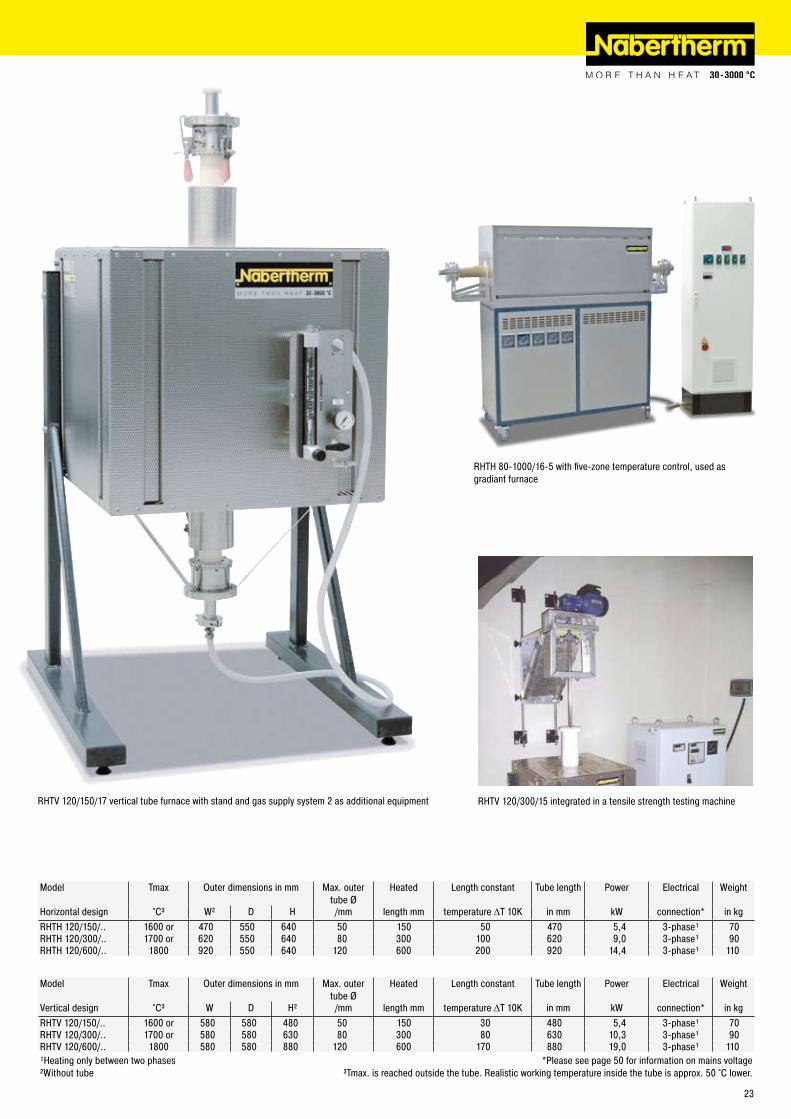
RHTV 1�0/150/17 vertical tube furnace with stand and gas supply system � as additional equipment
Model Tmax Outer dimensions in mm Max. outer tube Ø
Heated Length constant Tube length Power Electrical Weight
Horizontal design °C³ W² D H /mm length mm temperature ΔT 10K in mm kW connection* in kgRHTH 1�0/150/.. 1600 or 470 550 640 50 150 50 470 5,4 3-phase¹ 70RHTH 1�0/300/.. 1700 or 6�0 550 640 80 300 100 6�0 9,0 3-phase¹ 90RHTH 1�0/600/.. 1800 9�0 550 640 1�0 600 �00 9�0 14,4 3-phase¹ 110
Model Tmax Outer dimensions in mm Max. outer tube Ø
Heated Length constant Tube length Power Electrical Weight
Vertical design °C³ W D H² /mm length mm temperature ΔT 10K in mm kW connection* in kgRHTV 1�0/150/.. 1600 or 580 580 480 50 150 30 480 5,4 3-phase¹ 70RHTV 1�0/300/.. 1700 or 580 580 630 80 300 80 630 10,3 3-phase¹ 90RHTV 1�0/600/.. 1800 580 580 880 1�0 600 170 880 19,0 3-phase¹ 110¹Heating only between two phases *Please see page 50 for information on mains voltage²Without tube ³Tmax. is reached outside the tube. Realistic working temperature inside the tube is approx. 50 °C lower.
RHTH 80-1000/16-5 with five-zone temperature control, used as gradiant furnace
RHTV 1�0/300/15 integrated in a tensile strength testing machine
�3
Gas Supply Systems / Vacuum Operation for Tube Furnaces R, RT, RS, RHTC, RHTH and RHTV
When equipped with various equipment packages, the tube furnace series RS, RHTC, RHTH, and RHTV can be adapted for operation with nonflammable or flammable gasses or for vacuum operation. The different equipment packages can be delivered together with the furnace, or later as needed.
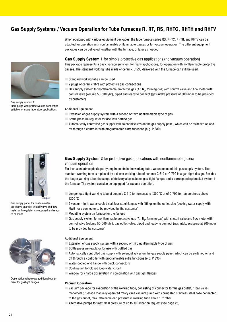
Gas Supply System 1 for simple protective gas applications (no vacuum operation)This package represents a basic version sufficient for many applications, for operation with nonflammable protective gasses. The standard working tube made of ceramic C 530 delivered with the furnace can still be used.
Standard working tube can be used� plugs of ceramic fibre with protective gas connectionsGas supply system for nonflammable protective gas (Ar, N�, forming gas) with shutoff valve and flow meter with control valve (volume 50-500 l/hr), piped and ready to connect (gas intake pressure at 300 mbar to be provided by customer)
Additional EquipmentExtension of gas supply system with a second or third nonflammable type of gasBottle pressure regulator for use with bottled gasAutomatically controlled gas supply with solenoid valves on the gas supply panel, which can be switched on and off through a controller with programmable extra functions (e.g. P 330)
Gas Supply System 2 for protective gas applications with nonflammable gases/vacuum operationFor increased atmospheric purity requirements in the working tube, we recommend this gas supply system. The standard working tube is replaced by a dense working tube of ceramic C 610 or C 799 in a gas-tight design. Besides the longer working tube, the scope of delivery also includes gas-tight flanges and a corresponding bracket system in the furnace. The system can also be equipped for vacuum operation.
Longer, gas-tight working tube of ceramic C 610 for furnaces to 1300 °C or of C 799 for temperatures above 1300 °C� vacuum-tight, water-cooled stainless steel flanges with fittings on the outlet side (cooling water supply with NW9 hose connector to be provided by the customer)Mounting system on furnace for the flangesGas supply system for nonflammable protective gas (Ar, N�, forming gas) with shutoff valve and flow meter with control valve (volume 50-500 l/hr), gas outlet valve, piped and ready to connect (gas intake pressure at 300 mbar to be provided by customer)
Additional EquipmentExtension of gas supply system with a second or third nonflammable type of gasBottle pressure regulator for use with bottled gasAutomatically controlled gas supply with solenoid valves on the gas supply panel, which can be switched on and off through a controller with programmable extra functions (e.g. P 330)Water-cooled end flange with quick connectorsCooling unit for closed loop water circuitWindow for charge observation in combination with gastight flanges
Vacuum OperationVacuum package for evacuation of the working tube, consisting of connector for the gas outlet, 1 ball valve, manometer, 1-stage manually operated rotary vane vacuum pump with corrugated stainless steel hose connected to the gas outlet, max. attainable end pressure in working tube about 10-� mbarAlternative pumps for max. final pressure of up to 10-5 mbar on request (see page �5)
Gas supply panel for nonflammable protective gas with shutoff valve and flow meter with regulator valve, piped and ready to connect
Gas supply system 1: Fibre plugs with protective gas connection, suitable for many laboratory applications
Observation window as additional equip-ment for gastight flanges
�4
Gas-tight design with water-cooled flanges
Vacuum pump stand for operation up to 10-5 mbar
RHTH 1�0-600/18 with gas supply system 4 for hydrogen operation
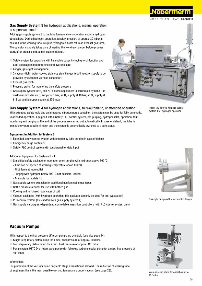
Vacuum Pumps
With respect to the final pressure different pumps are available (see also page 44):Single-step rotary piston pump for a max. final pressure of approx. �0 mbar.Two-step rotary piston pump for a max. final pressure of approx. 10-� mbar.Pump system PT70 Dry (rotary vane pump with following turbomolecular pump for a max. final pressure of 10-5 mbar.
Information:For protection of the vacuum pump only cold stage evacuation is allowed. The reduction of working tube strengthness limits the max. possible working temperature under vacuum (see page �8).
Gas Supply System 3 for hydrogen applications, manual operation in supervised modeAdding gas supply system 3 to the tube furnace allows operation under a hydrogen atmosphere. During hydrogen operation, a safety pressure of approx. 30 mbar is ensured in the working tube. Surplus hydrogen is burnt off in an exhaust gas torch. The operator manually takes care of inerting the working chamber before process start, after process end, and in case of default.
Safety system for operation with flammable gases including torch function and tube breakage monitoring (checking overpressure)Longer, gas-tight working tube� vacuum-tight, water-cooled stainless steel flanges (cooling water supply to be provided by customer via hose connector)Exhaust gas torchPressure switch for monitoring the safety pressureGas supply system for H� and N�. Volume adjustment is carried out by hand (the customer provides an H� supply at 1 bar, an N� supply at 10 bar, an O� supply at 6-8 bar and a propan supply at 300 mbar)
Gas Supply System 4 for hydrogen applications, fully-automatic, unattended operationWith extended safety logic and an integrated nitrogen purge container, the system can be used for fully-automatic, unattended operation. Equipped with a Safety-PLC control system, pre-purging, hydrogen inlet, operation, fault monitoring and purging at the end of the process are carried out automatically. In case of default, the tube is immediately purged with nitrogen and the system is automatically switched to a safe status.
Equipment in Addition to System 3Extended safety control system with emergency tube purging in case of defaultEmergency purge containerSafety-PLC control system with touchpanel for data input
Additional Equipment for Systems 3 - 4Simplified safety package for operation when purging with hydrogen above 800 °C
Tube can be opened at working temperature above 800 °CPilot flame at tube outletPurging with hydrogen below 800 °C not possible, lockedAvailable for models RS
Gas supply system extension for additional nonflammable gas typesBottle pressure reducer for use with bottled gasCooling unit for closed loop water circuitVacuum packages (with hydrogen operation, this package can only be used for pre-evacuation)PLC control system (as standard with gas supply system 4)Gas supply via program-dependent, controllable mass flow controllers (with PLC control system only)
----
�5
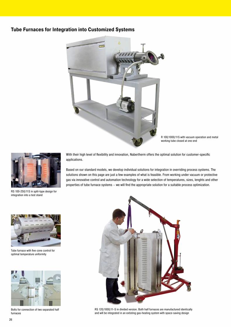
Tube Furnaces for Integration into Customized Systems
R 100/1000/11S with vacuum operation and metal working tube closed at one end
With their high level of flexibility and innovation, Nabertherm offers the optimal solution for customer-specific applications.
Based on our standard models, we develop individual solutions for integration in overriding process systems. The solutions shown on this page are just a few examples of what is feasible. From working under vacuum or protective gas via innovative control and automation technology for a wide selection of temperatures, sizes, lenghts and other properties of tube furnace systems – we will find the appropriate solution for a suitable process optimization.
RS 100-�50/11S in split-type design for integration into a test stand
Tube furnace with five-zone control for optimal temperature uniformity
Bolts for connection of two separated half furnaces
RS 1�0/1000/11-S in divided version. Both half furnaces are manufactured identically and will be integrated in an extisting gas-heating system with space-saving design
�6
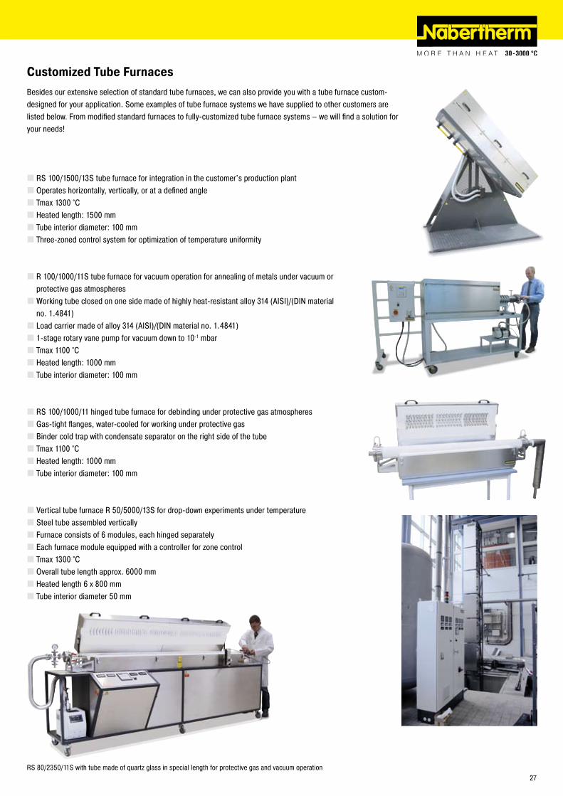
Customized Tube FurnacesBesides our extensive selection of standard tube furnaces, we can also provide you with a tube furnace custom-designed for your application. Some examples of tube furnace systems we have supplied to other customers are listed below. From modified standard furnaces to fully-customized tube furnace systems – we will find a solution for your needs!
RS 100/1500/13S tube furnace for integration in the customer's production plantOperates horizontally, vertically, or at a defined angleTmax 1300 °CHeated length: 1500 mmTube interior diameter: 100 mmThree-zoned control system for optimization of temperature uniformity
R 100/1000/11S tube furnace for vacuum operation for annealing of metals under vacuum or protective gas atmospheresWorking tube closed on one side made of highly heat-resistant alloy 314 (AISI)/(DIN material no. 1.4841)Load carrier made of alloy 314 (AISI)/(DIN material no. 1.4841)1-stage rotary vane pump for vacuum down to 10-1 mbar Tmax 1100 °CHeated length: 1000 mmTube interior diameter: 100 mm
RS 100/1000/11 hinged tube furnace for debinding under protective gas atmospheresGas-tight flanges, water-cooled for working under protective gasBinder cold trap with condensate separator on the right side of the tubeTmax 1100 °CHeated length: 1000 mmTube interior diameter: 100 mm
Vertical tube furnace R 50/5000/13S for drop-down experiments under temperatureSteel tube assembled verticallyFurnace consists of 6 modules, each hinged separatelyEach furnace module equipped with a controller for zone controlTmax 1300 °COverall tube length approx. 6000 mmHeated length 6 x 800 mmTube interior diameter 50 mm
RS 80/�350/11S with tube made of quartz glass in special length for protective gas and vacuum operation�7
Various working tubes as option
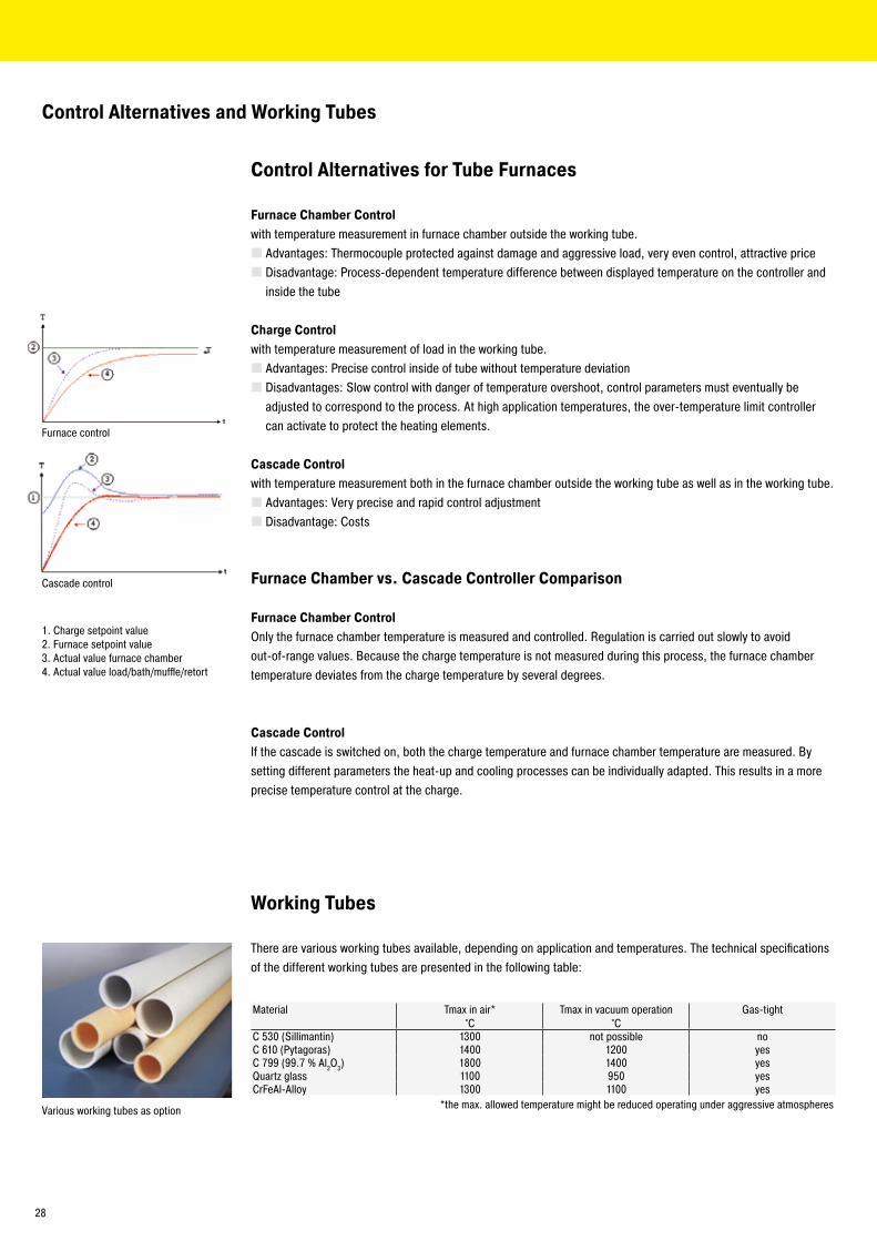
Control Alternatives and Working Tubes
Working Tubes
There are various working tubes available, depending on application and temperatures. The technical specifications of the different working tubes are presented in the following table:
Material Tmax in air*°C
Tmax in vacuum operation°C
Gas-tight
C 530 (Sillimantin) 1300 not possible noC 610 (Pytagoras) 1400 1�00 yesC 799 (99.7 % Al�O3) 1800 1400 yesQuartz glass 1100 950 yesCrFeAl-Alloy 1300 1100 yes
*the max. allowed temperature might be reduced operating under aggressive atmospheres
Control Alternatives for Tube Furnaces
Furnace Chamber Control with temperature measurement in furnace chamber outside the working tube.
Advantages: Thermocouple protected against damage and aggressive load, very even control, attractive priceDisadvantage: Process-dependent temperature difference between displayed temperature on the controller and inside the tube
Charge Control with temperature measurement of load in the working tube.
Advantages: Precise control inside of tube without temperature deviationDisadvantages: Slow control with danger of temperature overshoot, control parameters must eventually be adjusted to correspond to the process. At high application temperatures, the over-temperature limit controller can activate to protect the heating elements.
Cascade Control with temperature measurement both in the furnace chamber outside the working tube as well as in the working tube.
Advantages: Very precise and rapid control adjustmentDisadvantage: Costs
Furnace Chamber vs. Cascade Controller Comparison
Furnace Chamber ControlOnly the furnace chamber temperature is measured and controlled. Regulation is carried out slowly to avoid out-of-range values. Because the charge temperature is not measured during this process, the furnace chamber temperature deviates from the charge temperature by several degrees.
Cascade ControlIf the cascade is switched on, both the charge temperature and furnace chamber temperature are measured. By setting different parameters the heat-up and cooling processes can be individually adapted. This results in a more precise temperature control at the charge.
1. Charge setpoint value�. Furnace setpoint value3. Actual value furnace chamber4. Actual value load/bath/muffle/retort
Furnace control
Cascade control
�8
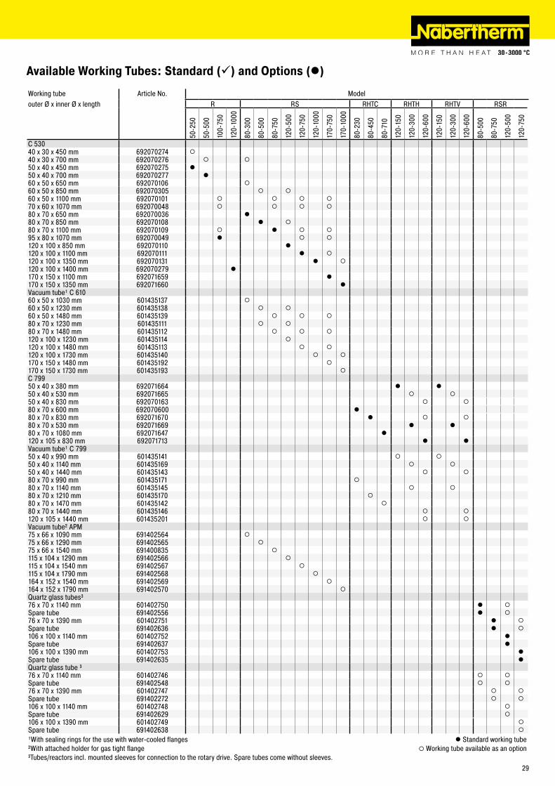
Available Working Tubes: Standard () and Options (l)
Working tube Article No. Modelouter Ø x inner Ø x length R RS RHTC RHTH RHTV RSR
50-�
50
50-5
00
100-
750
1�0-
1000
80-3
00
80-5
00
80-7
50
1�0-
500
1�0-
750
1�0-
1000
170-
750
170-
1000
80-�
30
80-4
50
80-7
10
1�0-
150
1�0-
300
1�0-
600
1�0-
150
1�0-
300
1�0-
600
80-5
00
80-7
50
1�0-
500
1�0-
750
C 53040 x 30 x 450 mm 69�070�74 ¡40 x 30 x 700 mm 69�070�76 ¡ ¡50 x 40 x 450 mm 69�070�75 l50 x 40 x 700 mm 69�070�77 l60 x 50 x 650 mm 69�070106 ¡60 x 50 x 850 mm 69�070305 ¡ ¡60 x 50 x 1100 mm 69�070101 ¡ ¡ ¡ ¡70 x 60 x 1070 mm 69�070048 ¡ ¡ ¡ ¡80 x 70 x 650 mm 69�070036 l80 x 70 x 850 mm 69�070108 l ¡80 x 70 x 1100 mm 69�070109 ¡ l ¡ ¡95 x 80 x 1070 mm 69�070049 l ¡ ¡1�0 x 100 x 850 mm 69�070110 l1�0 x 100 x 1100 mm 69�070111 l ¡1�0 x 100 x 1350 mm 69�070131 l ¡1�0 x 100 x 1400 mm 69�070�79 l170 x 150 x 1100 mm 69�071659 l170 x 150 x 1350 mm 69�071660 lVacuum tube¹ C 61060 x 50 x 1030 mm 601435137 ¡60 x 50 x 1�30 mm 601435138 ¡ ¡60 x 50 x 1480 mm 601435139 ¡ ¡ ¡80 x 70 x 1�30 mm 601435111 ¡ ¡80 x 70 x 1480 mm 60143511� ¡ ¡ ¡1�0 x 100 x 1�30 mm 601435114 ¡1�0 x 100 x 1480 mm 601435113 ¡ ¡1�0 x 100 x 1730 mm 601435140 ¡ ¡170 x 150 x 1480 mm 60143519� ¡170 x 150 x 1730 mm 601435193 ¡C 79950 x 40 x 380 mm 69�071664 l l50 x 40 x 530 mm 69�071665 ¡ ¡50 x 40 x 830 mm 69�070163 ¡ ¡80 x 70 x 600 mm 69�070600 l80 x 70 x 830 mm 69�071670 l ¡ ¡80 x 70 x 530 mm 69�071669 l l80 x 70 x 1080 mm 69�071647 l1�0 x 105 x 830 mm 69�071713 l lVacuum tube¹ C 79950 x 40 x 990 mm 601435141 ¡ ¡50 x 40 x 1140 mm 601435169 ¡ ¡50 x 40 x 1440 mm 601435143 ¡ ¡80 x 70 x 990 mm 601435171 ¡80 x 70 x 1140 mm 601435145 ¡ ¡80 x 70 x 1�10 mm 601435170 ¡80 x 70 x 1470 mm 60143514� ¡80 x 70 x 1440 mm 601435146 ¡ ¡1�0 x 105 x 1440 mm 601435�01 ¡ ¡Vacuum tube² APM75 x 66 x 1090 mm 69140�564 ¡75 x 66 x 1�90 mm 69140�565 ¡75 x 66 x 1540 mm 691400835 ¡115 x 104 x 1�90 mm 69140�566 ¡115 x 104 x 1540 mm 69140�567 ¡115 x 104 x 1790 mm 69140�568 ¡164 x 15� x 1540 mm 69140�569 ¡164 x 15� x 1790 mm 69140�570 ¡Quartz glass tubes³76 x 70 x 1140 mm 60140�750 l ¡Spare tube 69140�556 l ¡76 x 70 x 1390 mm 60140�751 l ¡Spare tube 69140�636 l ¡106 x 100 x 1140 mm 60140�75� lSpare tube 69140�637 l106 x 100 x 1390 mm 60140�753 lSpare tube 69140�635 lQuartz glass tube ³76 x 70 x 1140 mm 60140�746 ¡ ¡Spare tube 69140�548 ¡ ¡76 x 70 x 1390 mm 60140�747 ¡ ¡Spare tube 69140��7� ¡ ¡106 x 100 x 1140 mm 60140�748 ¡Spare tube 69140�6�9 ¡106 x 100 x 1390 mm 60140�749 ¡Spare tube 69140�638 ¡
¹With sealing rings for the use with water-cooled flanges l Standard working tube²With attached holder for gas tight flange ¡ Working tube available as an option³Tubes/reactors incl. mounted sleeves for connection to the rotary drive. Spare tubes come without sleeves.
�9
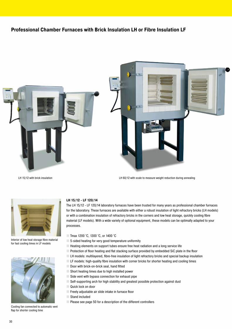
Professional Chamber Furnaces with Brick Insulation LH or Fibre Insulation LF
LH 15/12 - LF 120/14The LH 15/1� - LF 1�0/14 laboratory furnaces have been trusted for many years as professional chamber furnaces for the laboratory. These furnaces are available with either a robust insulation of light refractory bricks (LH models) or with a combination insulation of refractory bricks in the corners and low heat storage, quickly cooling fibre material (LF models). With a wide variety of optional equipment, these models can be optimally adapted to your processes.
Tmax 1�00 °C, 1300 °C, or 1400 °C5-sided heating for very good temperature uniformityHeating elements on support tubes ensure free heat radiation and a long service lifeProtection of floor heating and flat stacking surface provided by embedded SiC plate in the floorLH models: multilayered, fibre-free insulation of light refractory bricks and special backup insulationLF models: high-quality fibre insulation with corner bricks for shorter heating and cooling timesDoor with brick-on-brick seal, hand fittedShort heating times due to high installed powerSide vent with bypass connection for exhaust pipeSelf-supporting arch for high stability and greatest possible protection against dustQuick lock on doorFreely adjustable air slide intake in furnace floorStand includedPlease see page 50 for a description of the different controllers
Interior of low heat storage fibre material for fast cooling times in LF models
Cooling fan connected to automatic vent flap for shorter cooling time
LH 15/1� with brick insulation LH 60/1� with scale to measure weight reduction during annealing
30
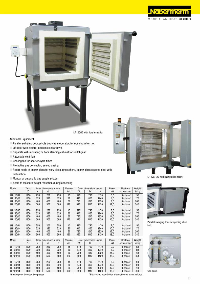
Parallel swinging door for opening whenhot
LF 1�0/1� with fibre insulation
Additional EquipmentParallel swinging door, pivots away from operator, for opening when hotLift door with electro-mechanic linear driveSeparate wall-mounting or floor standing cabinet for switchgearAutomatic vent flapCooling fan for shorter cycle timesProtective gas connector, sealed casingRetort made of quartz glass for very clean atmosphere, quartz glass covered door with lid functionManual or automatic gas supply systemScale to measure weight reduction during annealing
Model Tmax Inner dimensions in mm Volume Outer dimensions in mm Power Electrical Weight°C w d h in L W D H kW connection* in kg
LH 15/1� 1�00 �50 �50 �50 15 570 790 1170 5,0 3-phase¹ 150LH 30/1� 1�00 3�0 3�0 3�0 30 640 860 1�40 7,0 3-phase¹ 170LH 60/1� 1�00 400 400 400 60 7�0 1010 13�0 8,0 3-phase �60LH 1�0/1� 1�00 500 500 500 1�0 8�0 1110 14�0 1�,0 3-phase 340
LH 15/13 1300 �50 �50 �50 15 570 790 1170 7,0 3-phase¹ 150LH 30/13 1300 3�0 3�0 3�0 30 640 860 1�40 8,0 3-phase¹ 170LH 60/13 1300 400 400 400 60 7�0 1010 13�0 11,0 3-phase �60LH 1�0/13 1300 500 500 500 1�0 8�0 1110 14�0 15,0 3-phase 340
LH 15/14 1400 �50 �50 �50 15 570 790 1170 8,0 3-phase¹ 150LH 30/14 1400 3�0 3�0 3�0 30 640 860 1�40 10,0 3-phase¹ 170LH 60/14 1400 400 400 400 60 7�0 1010 13�0 1�,0 3-phase �60LH 1�0/14 1400 500 500 500 1�0 8�0 1110 14�0 18,0 3-phase 340
Model Tmax Inner dimensions in mm Volume Outer dimensions in mm Power Electrical Weight°C w d h in L W D H kW connection* in kg
LF 15/13 1300 �50 �50 �50 15 570 790 1170 7,0 3-phase¹ 130LF 30/13 1300 3�0 3�0 3�0 30 640 860 1�40 8,0 3-phase¹ 150LF 60/13 1300 400 400 400 60 7�0 1010 13�0 11,0 3-phase �30LF 1�0/13 1300 500 500 500 1�0 8�0 1110 14�0 15,0 3-phase 300
LF 15/14 1400 �50 �50 �50 15 570 790 1170 8,0 3-phase¹ 130LF 30/14 1400 3�0 3�0 3�0 30 640 860 1�40 10,0 3-phase¹ 150LF 60/14 1400 400 400 400 60 7�0 1010 13�0 1�,0 3-phase �30LF 1�0/14 1400 500 500 500 1�0 8�0 1110 14�0 18,0 3-phase 300¹Heating only between two phases *Please see page 50 for information on mains voltage
Gas panel
LH 1�0/1�S with quartz glass retort
31
GR 1300/13
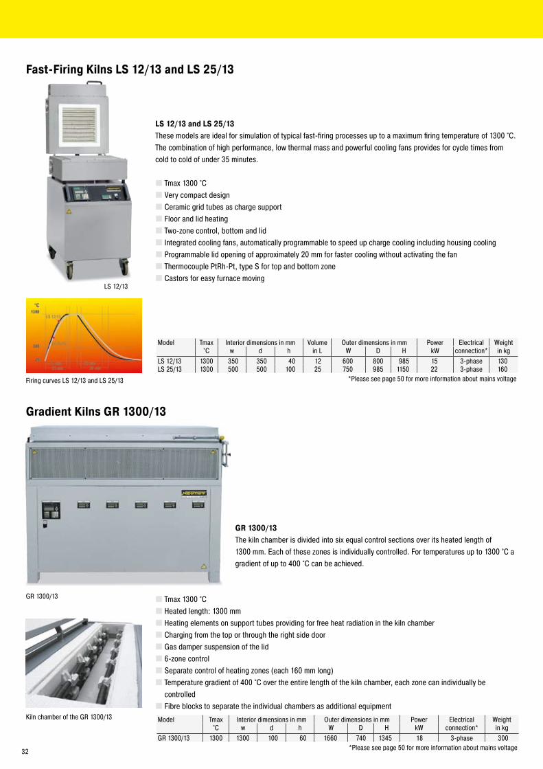
LS 1�/13
Fast-Firing Kilns LS 12/13 and LS 25/13
LS 12/13 and LS 25/13These models are ideal for simulation of typical fast-firing processes up to a maximum firing temperature of 1300 °C.The combination of high performance, low thermal mass and powerful cooling fans provides for cycle times fromcold to cold of under 35 minutes.
Tmax 1300 °CVery compact designCeramic grid tubes as charge supportFloor and lid heatingTwo-zone control, bottom and lidIntegrated cooling fans, automatically programmable to speed up charge cooling including housing coolingProgrammable lid opening of approximately �0 mm for faster cooling without activating the fanThermocouple PtRh-Pt, type S for top and bottom zoneCastors for easy furnace moving
Model Tmax Interior dimensions in mm Volume Outer dimensions in mm Power Electrical Weight°C w d h in L W D H kW connection* in kg
LS 1�/13 1300 350 350 40 1� 600 800 985 15 3-phase 130LS �5/13 1300 500 500 100 �5 750 985 1150 �� 3-phase 160
*Please see page 50 for more information about mains voltageFiring curves LS 1�/13 and LS �5/13
Gradient Kilns GR 1300/13
Kiln chamber of the GR 1300/13
GR 1300/13The kiln chamber is divided into six equal control sections over its heated length of 1300 mm. Each of these zones is individually controlled. For temperatures up to 1300 °C a gradient of up to 400 °C can be achieved.
Tmax 1300 °CHeated length: 1300 mmHeating elements on support tubes providing for free heat radiation in the kiln chamberCharging from the top or through the right side doorGas damper suspension of the lid6-zone controlSeparate control of heating zones (each 160 mm long)Temperature gradient of 400 °C over the entire length of the kiln chamber, each zone can individually be controlledFibre blocks to separate the individual chambers as additional equipment
Model Tmax Interior dimensions in mm Outer dimensions in mm Power Electrical Weight°C w d h W D H kW connection* in kg
GR 1300/13 1300 1300 100 60 1660 740 1345 18 3-phase 300*Please see page 50 for more information about mains voltage3�
K 1/10
KC �/15
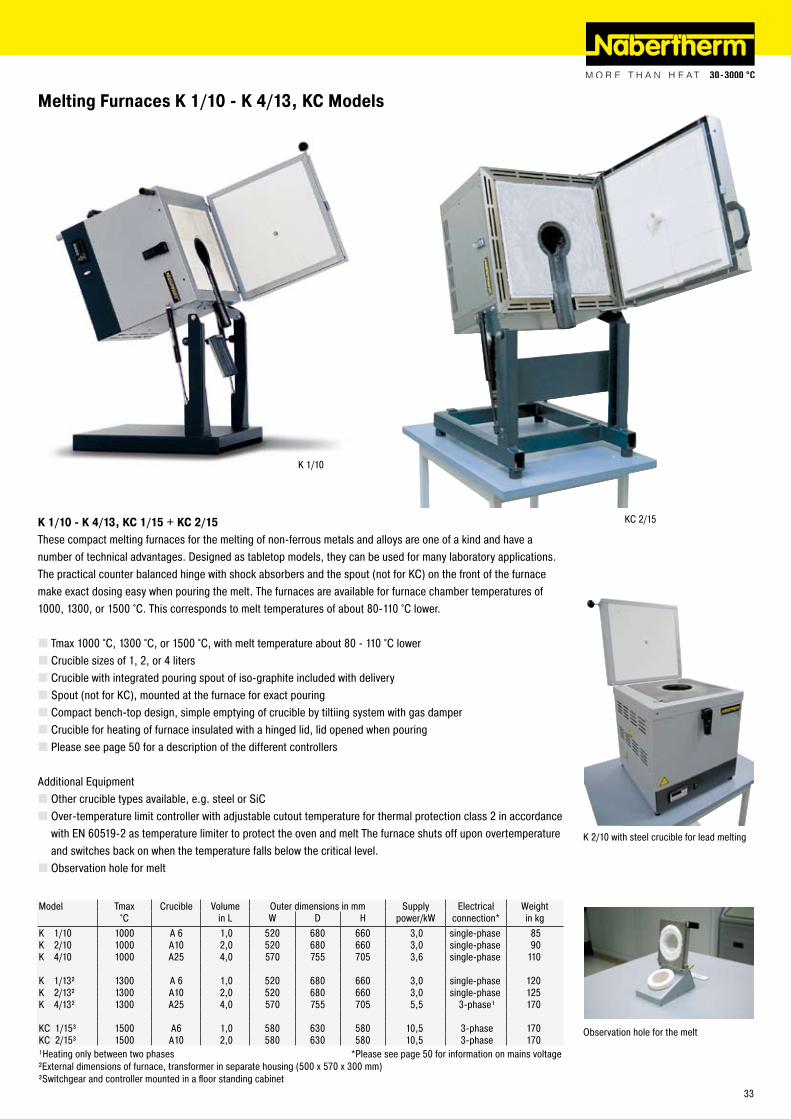
Model Tmax Crucible Volume Outer dimensions in mm Supply Electrical Weight°C in L W D H power/kW connection* in kg
K 1/10 1000 A 6 1,0 5�0 680 660 3,0 single-phase 85K �/10 1000 A10 �,0 5�0 680 660 3,0 single-phase 90K 4/10 1000 A�5 4,0 570 755 705 3,6 single-phase 110
K 1/13² 1300 A 6 1,0 5�0 680 660 3,0 single-phase 1�0K �/13² 1300 A10 �,0 5�0 680 660 3,0 single-phase 1�5K 4/13² 1300 A�5 4,0 570 755 705 5,5 3-phase¹ 170
KC 1/15³ 1500 A6 1,0 580 630 580 10,5 3-phase 170KC �/15³ 1500 A10 �,0 580 630 580 10,5 3-phase 170¹Heating only between two phases *Please see page 50 for information on mains voltage²External dimensions of furnace, transformer in separate housing (500 x 570 x 300 mm)³Switchgear and controller mounted in a floor standing cabinet
Melting Furnaces K 1/10 - K 4/13, KC Models
K 1/10 - K 4/13, KC 1/15 + KC 2/15These compact melting furnaces for the melting of non-ferrous metals and alloys are one of a kind and have a number of technical advantages. Designed as tabletop models, they can be used for many laboratory applications. The practical counter balanced hinge with shock absorbers and the spout (not for KC) on the front of the furnace make exact dosing easy when pouring the melt. The furnaces are available for furnace chamber temperatures of 1000, 1300, or 1500 °C. This corresponds to melt temperatures of about 80-110 °C lower.
Tmax 1000 °C, 1300 °C, or 1500 °C, with melt temperature about 80 - 110 °C lowerCrucible sizes of 1, �, or 4 litersCrucible with integrated pouring spout of iso-graphite included with deliverySpout (not for KC), mounted at the furnace for exact pouringCompact bench-top design, simple emptying of crucible by tiltiing system with gas damperCrucible for heating of furnace insulated with a hinged lid, lid opened when pouringPlease see page 50 for a description of the different controllers
Additional EquipmentOther crucible types available, e.g. steel or SiCOver-temperature limit controller with adjustable cutout temperature for thermal protection class � in accordance with EN 60519-� as temperature limiter to protect the oven and melt The furnace shuts off upon overtemperature and switches back on when the temperature falls below the critical level.Observation hole for melt
Observation hole for the melt
K �/10 with steel crucible for lead melting
33
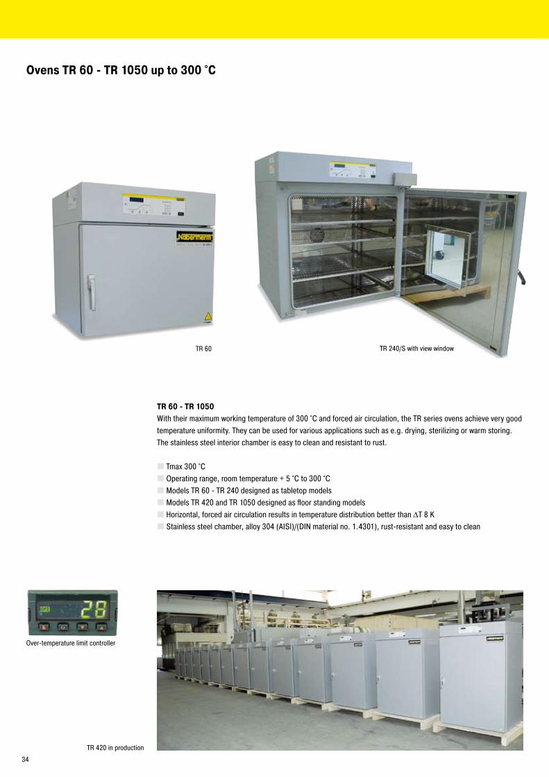
TR 60
Ovens TR 60 - TR 1050 up to 300 °C
TR �40/S with view window
Over-temperature limit controller
TR 60 - TR 1050With their maximum working temperature of 300 °C and forced air circulation, the TR series ovens achieve very good temperature uniformity. They can be used for various applications such as e.g. drying, sterilizing or warm storing. The stainless steel interior chamber is easy to clean and resistant to rust.
Tmax 300 °COperating range, room temperature + 5 °C to 300 °CModels TR 60 - TR �40 designed as tabletop modelsModels TR 4�0 and TR 1050 designed as floor standing modelsHorizontal, forced air circulation results in temperature distribution better than ΔT 8 KStainless steel chamber, alloy 304 (AISI)/(DIN material no. 1.4301), rust-resistant and easy to clean
TR 4�0 in production
34
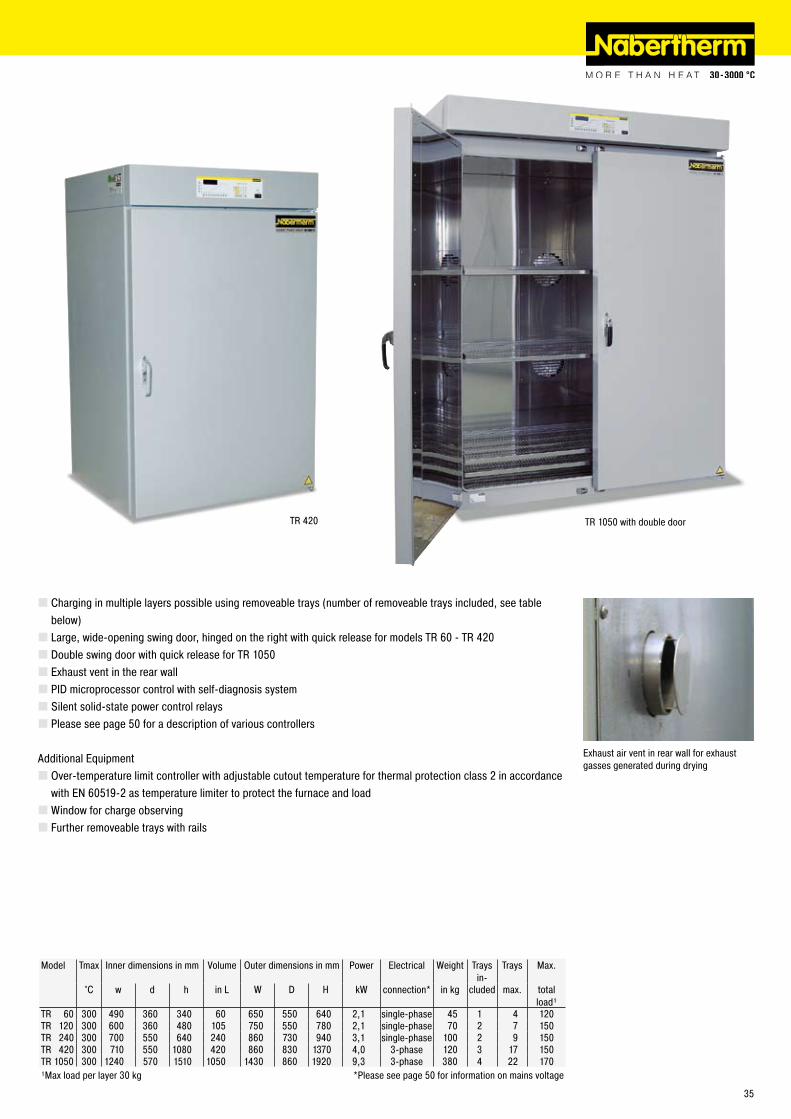
TR 4�0
Model Tmax Inner dimensions in mm Volume Outer dimensions in mm Power Electrical Weight Trays in-
Trays Max.
°C w d h in L W D H kW connection* in kg cluded max. total load¹
TR 60 300 490 360 340 60 650 550 640 �,1 single-phase 45 1 4 1�0TR 1�0 300 600 360 480 105 750 550 780 �,1 single-phase 70 � 7 150TR �40 300 700 550 640 �40 860 730 940 3,1 single-phase 100 � 9 150TR 4�0 300 710 550 1080 4�0 860 830 1370 4,0 3-phase 1�0 3 17 150TR 1050 300 1�40 570 1510 1050 1430 860 19�0 9,3 3-phase 380 4 �� 170¹Max load per layer 30 kg *Please see page 50 for information on mains voltage
Exhaust air vent in rear wall for exhaust gasses generated during drying
TR 1050 with double door
Charging in multiple layers possible using removeable trays (number of removeable trays included, see table below)Large, wide-opening swing door, hinged on the right with quick release for models TR 60 - TR 4�0Double swing door with quick release for TR 1050Exhaust vent in the rear wallPID microprocessor control with self-diagnosis systemSilent solid-state power control relaysPlease see page 50 for a description of various controllers
Additional EquipmentOver-temperature limit controller with adjustable cutout temperature for thermal protection class � in accordance with EN 60519-� as temperature limiter to protect the furnace and loadWindow for charge observingFurther removeable trays with rails
35
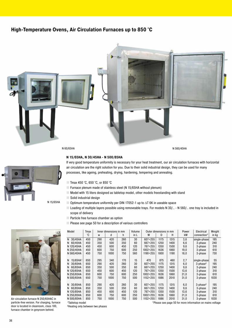
N 15/65HA
N 560/45HAN 60/65HA
High-Temperature Ovens, Air Circulation Furnaces up to 850 °C
N 15/65HA, N 30/45HA - N 500/85HAIf very good temperature uniformity is necessary for your heat treatment, our air circulation furnaces with horizontal air circulation are the right solution for you. Due to their solid industrial design, they can be used for many processes, like ageing, preheating, drying, hardening, tempering and annealing.
Tmax 450 °C, 650 °C, or 850 °CFurnace plenum made of stainless steel (N 15/65HA without plenum)Model with 15 liters designed as tabletop model, other models freestanding with standSolid industrial designOptimum temperature uniformity per DIN 1705�-1 up to ΔT 6K in useable spaceLoading of multiple layers possible using removeable trays. For models N 30/.. - N 560/.. one tray is included in scope of deliveryParticle free furnace chamber as optionPlease see page 50 for a description of various controllers
Model Tmax Inner dimensions in mm Volume Outer dimensions in mm Power Electrical Weight°C w d h in L W D H kW connection* in kg
N 30/45HA 450 �90 4�0 �60 30 607+�55 1175 1315 3,6 single-phase 195N 60/45HA 450 350 500 350 60 667+�55 1�50 1400 6,6 3-phase �40N 1�0/45HA 450 450 600 450 1�0 767+�55 1350 1500 9,6 3-phase 310N �50/45HA 450 600 750 600 �50 100�+�55 1636 1860 19,0 3-phase 610N 560/45HA 450 750 1000 750 560 1190+�55 1800 1190 18,0 3-phase 730
N 15/65HA¹ 650 �95 340 170 15 470 875 460 �,7 single-phase 55N 30/65HA 650 �90 4�0 �60 30 607+�55 1175 1315 6,0 3-phase² 195N 60/65HA 650 350 500 350 60 667+�55 1�50 1400 9,6 3-phase �40N 1�0/65HA 650 450 600 450 1�0 767+�55 1350 1500 13,6 3-phase 310N �50/65HA 650 600 750 600 �50 100�+�55 1636 1860 �1,0 3-phase 610N 500/65HA 650 750 1000 750 500 115�+�55 1886 �010 31,0 3-phase 1030
N 30/85HA 850 �90 4�0 �60 30 607+�55 1175 1315 6,0 3-phase² 195N 60/85HA 850 350 500 350 60 667+�55 1�50 1400 9,6 3-phase �40N 1�0/85HA 850 450 600 450 1�0 767+�55 1350 1500 13,6 3-phase 310N �50/85HA 850 600 750 600 �50 100�+�55 1636 1860 �1,0 3-phase 610N 500/85HA 850 750 1000 750 500 115�+�55 1886 �010 31,0 3-phase 1030¹Tabletop model *Please see page 50 for more information on mains voltage²Heating only between two phases
Air-circulation furnace N �50/65HAC in particle-free version. For charging, furnace door is located in cleanroom, class 100, furnace chamber in greyroom behind.
36
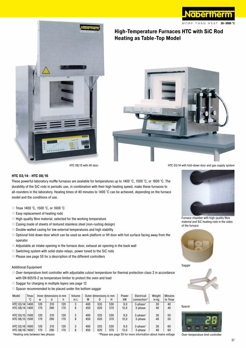
High-Temperature Furnaces HTC with SiC Rod Heating as Table-Top Model
HTC 03/14 - HTC 08/16These powerful laboratory muffle furnaces are available for temperatures up to 1400 °C, 1500 °C, or 1600 °C. The durability of the SiC rods in periodic use, in combination with their high heating speed, make these furnaces to all-rounders in the laboratory. Heating times of 40 minutes to 1400 °C can be achieved, depending on the furnace model and the conditions of use.
Tmax 1400 °C, 1500 °C, or 1600 °CEasy replacement of heating rodsHigh-quality fibre material, selected for the working temperatureCasing made of sheets of textured stainless steel (non-rusting design)Double-walled casing for low external temperatures and high stabilityOptional fold-down door which can be used as work platform or lift door with hot surface facing away from the operatorAdjustable air intake opening in the furnace door, exhaust air opening in the back wallSwitching system with solid-state-relays, power tuned to the SiC rodsPlease see page 50 for a description of the different controllers
Additional EquipmentOver-temperature limit controller with adjustable cutout temperature for thermal protection class � in accordance with EN 60519-� as temperature limiter to protect the oven and loadSaggar for charging in multiple layers see page 13Spacer recommended to be placed under the bottom saggar
Furnace chamber with high-quality fibre material and SiC heating rods in the sides of the furnace
Model Tmax Inner dimensions in mm Volume Outer dimensions in mm Power Electrical Weight Minutes°C w d h in L W D H kW connection* in kg to Tmax
HTC 03/14 1400 1�0 �10 1�0 3 400 535 530 9,0 3-phase¹ 30 40HTC 08/14 1400 170 �90 170 8 450 6�0 570 13,0 3-phase 40 40
HTC 03/15 1500 1�0 �10 1�0 3 400 535 530 9,0 3-phase¹ 30 50HTC 08/15 1500 170 �90 170 8 450 6�0 570 13,0 3-phase 40 50
HTC 03/16 1600 1�0 �10 1�0 3 400 535 530 9,0 3-phase¹ 30 60HTC 08/16 1600 170 �90 170 8 450 6�0 570 13,0 3-phase 40 60¹Heating only between two phases *Please see page 50 for more information about mains voltage Over-temperature limit controller
HTC 03/14 with fold-down door and gas supply system
Saggar
HTC 08/15 with lift door
Spacer
37
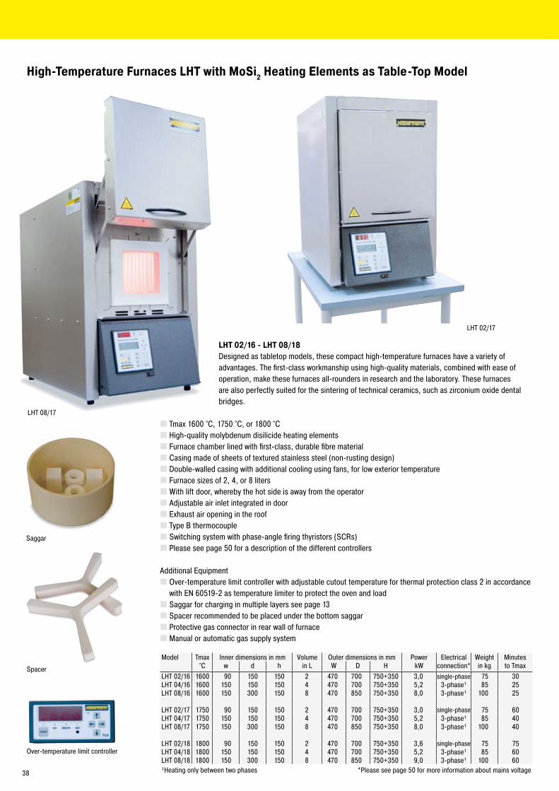
LHT 0�/17
LHT 08/17
High-Temperature Furnaces LHT with MoSi2 Heating Elements as Table-Top Model
LHT 02/16 - LHT 08/18Designed as tabletop models, these compact high-temperature furnaces have a variety of advantages. The first-class workmanship using high-quality materials, combined with ease of operation, make these furnaces all-rounders in research and the laboratory. These furnaces are also perfectly suited for the sintering of technical ceramics, such as zirconium oxide dental bridges.
Tmax 1600 °C, 1750 °C, or 1800 °CHigh-quality molybdenum disilicide heating elementsFurnace chamber lined with first-class, durable fibre materialCasing made of sheets of textured stainless steel (non-rusting design)Double-walled casing with additional cooling using fans, for low exterior temperatureFurnace sizes of �, 4, or 8 litersWith lift door, whereby the hot side is away from the operatorAdjustable air inlet integrated in doorExhaust air opening in the roofType B thermocoupleSwitching system with phase-angle firing thyristors (SCRs)Please see page 50 for a description of the different controllers
Additional EquipmentOver-temperature limit controller with adjustable cutout temperature for thermal protection class � in accordance with EN 60519-� as temperature limiter to protect the oven and loadSaggar for charging in multiple layers see page 13Spacer recommended to be placed under the bottom saggarProtective gas connector in rear wall of furnaceManual or automatic gas supply system
Model Tmax Inner dimensions in mm Volume Outer dimensions in mm Power Electrical Weight Minutes°C w d h in L W D H kW connection* in kg to Tmax
LHT 0�/16 1600 90 150 150 � 470 700 750+350 3,0 single-phase 75 30LHT 04/16 1600 150 150 150 4 470 700 750+350 5,� 3-phase¹ 85 �5LHT 08/16 1600 150 300 150 8 470 850 750+350 8,0 3-phase¹ 100 �5
LHT 0�/17 1750 90 150 150 � 470 700 750+350 3,0 single-phase 75 60LHT 04/17 1750 150 150 150 4 470 700 750+350 5,� 3-phase¹ 85 40LHT 08/17 1750 150 300 150 8 470 850 750+350 8,0 3-phase¹ 100 40
LHT 0�/18 1800 90 150 150 � 470 700 750+350 3,6 single-phase 75 75LHT 04/18 1800 150 150 150 4 470 700 750+350 5,� 3-phase¹ 85 60LHT 08/18 1800 150 300 150 8 470 850 750+350 9,0 3-phase¹ 100 60¹Heating only between two phases *Please see page 50 for more information about mains voltage
Over-temperature limit controller
Saggar
Spacer
38
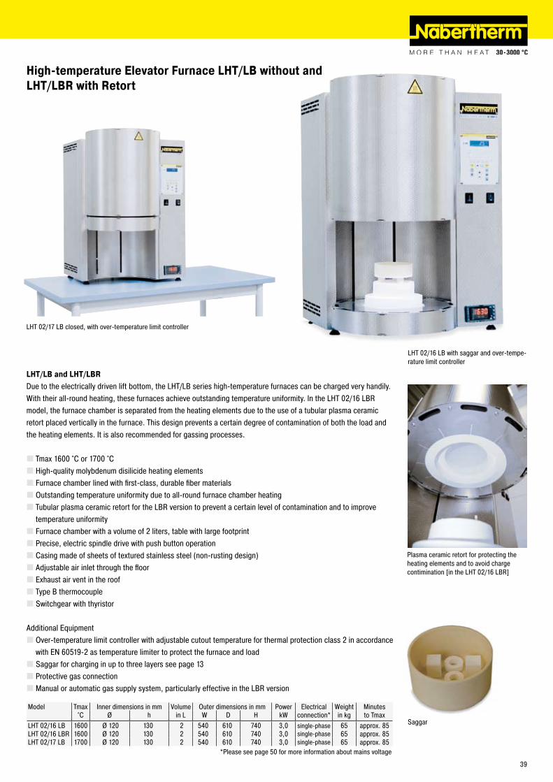
Model Tmax Inner dimensions in mm Volume Outer dimensions in mm Power Electrical Weight Minutes°C Ø h in L W D H kW connection* in kg to Tmax
LHT 0�/16 LB 1600 Ø 1�0 130 � 540 610 740 3,0 single-phase 65 approx. 85LHT 0�/16 LBR 1600 Ø 1�0 130 � 540 610 740 3,0 single-phase 65 approx. 85LHT 0�/17 LB 1700 Ø 1�0 130 � 540 610 740 3,0 single-phase 65 approx. 85
*Please see page 50 for more information about mains voltage
LHT 0�/16 LB with saggar and over-tempe-rature limit controller
LHT 0�/17 LB closed, with over-temperature limit controller
Saggar
High-temperature Elevator Furnace LHT/LB without andLHT/LBR with Retort
Plasma ceramic retort for protecting the heating elements and to avoid charge contimination [in the LHT 0�/16 LBR]
LHT/LB and LHT/LBRDue to the electrically driven lift bottom, the LHT/LB series high-temperature furnaces can be charged very handily. With their all-round heating, these furnaces achieve outstanding temperature uniformity. In the LHT 0�/16 LBR model, the furnace chamber is separated from the heating elements due to the use of a tubular plasma ceramic retort placed vertically in the furnace. This design prevents a certain degree of contamination of both the load and the heating elements. It is also recommended for gassing processes.
Tmax 1600 °C or 1700 °CHigh-quality molybdenum disilicide heating elementsFurnace chamber lined with first-class, durable fiber materialsOutstanding temperature uniformity due to all-round furnace chamber heatingTubular plasma ceramic retort for the LBR version to prevent a certain level of contamination and to improve temperature uniformityFurnace chamber with a volume of � liters, table with large footprintPrecise, electric spindle drive with push button operationCasing made of sheets of textured stainless steel (non-rusting design)Adjustable air inlet through the floorExhaust air vent in the roofType B thermocoupleSwitchgear with thyristor
Additional EquipmentOver-temperature limit controller with adjustable cutout temperature for thermal protection class � in accordance with EN 60519-� as temperature limiter to protect the furnace and loadSaggar for charging in up to three layers see page 13Protective gas connectionManual or automatic gas supply system, particularly effective in the LBR version
39
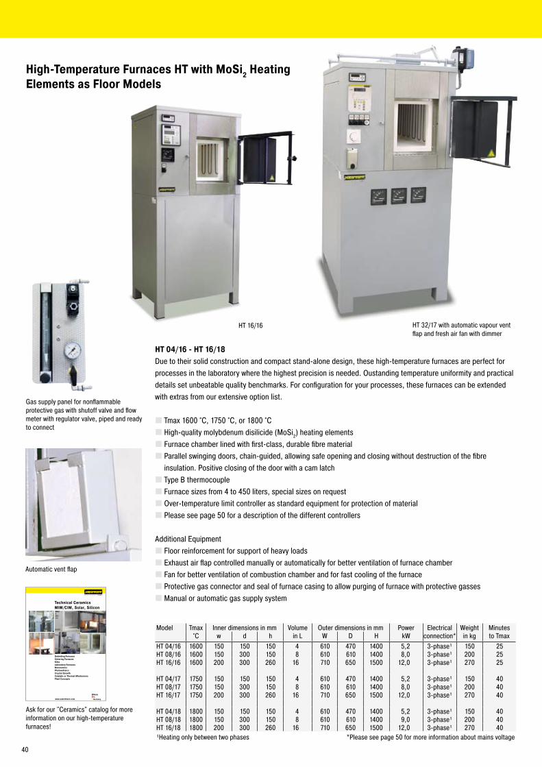
www.nabertherm.com
MadeinGermany
Technical CeramicsMIM/CIM, Solar, Silicon
Debinding FurnacesSintering FurnacesKilnsLaboratory Furnaces BioceramicsPhotovoltaicsCrystal GrowthCatalytic or Thermal AfterburnersPlant Concepts
HT 16/16
High-Temperature Furnaces HT with MoSi2 HeatingElements as Floor Models
HT 04/16 - HT 16/18Due to their solid construction and compact stand-alone design, these high-temperature furnaces are perfect for processes in the laboratory where the highest precision is needed. Oustanding temperature uniformity and practical details set unbeatable quality benchmarks. For configuration for your processes, these furnaces can be extended with extras from our extensive option list.
Tmax 1600 °C, 1750 °C, or 1800 °CHigh-quality molybdenum disilicide (MoSi�) heating elementsFurnace chamber lined with first-class, durable fibre materialParallel swinging doors, chain-guided, allowing safe opening and closing without destruction of the fibre insulation. Positive closing of the door with a cam latchType B thermocoupleFurnace sizes from 4 to 450 liters, special sizes on requestOver-temperature limit controller as standard equipment for protection of materialPlease see page 50 for a description of the different controllers
Additional EquipmentFloor reinforcement for support of heavy loadsExhaust air flap controlled manually or automatically for better ventilation of furnace chamberFan for better ventilation of combustion chamber and for fast cooling of the furnaceProtective gas connector and seal of furnace casing to allow purging of furnace with protective gassesManual or automatic gas supply system
Automatic vent flap
Model Tmax Inner dimensions in mm Volume Outer dimensions in mm Power Electrical Weight Minutes°C w d h in L W D H kW connection* in kg to Tmax
HT 04/16 1600 150 150 150 4 610 470 1400 5,� 3-phase¹ 150 �5HT 08/16 1600 150 300 150 8 610 610 1400 8,0 3-phase¹ �00 �5HT 16/16 1600 �00 300 �60 16 710 650 1500 1�,0 3-phase¹ �70 �5
HT 04/17 1750 150 150 150 4 610 470 1400 5,� 3-phase¹ 150 40HT 08/17 1750 150 300 150 8 610 610 1400 8,0 3-phase¹ �00 40HT 16/17 1750 �00 300 �60 16 710 650 1500 1�,0 3-phase¹ �70 40
HT 04/18 1800 150 150 150 4 610 470 1400 5,� 3-phase¹ 150 40HT 08/18 1800 150 300 150 8 610 610 1400 9,0 3-phase¹ �00 40HT 16/18 1800 �00 300 �60 16 710 650 1500 1�,0 3-phase¹ �70 40¹Heating only between two phases *Please see page 50 for more information about mains voltage
Ask for our "Ceramics" catalog for more information on our high-temperature furnaces!
HT 3�/17 with automatic vapour vent flap and fresh air fan with dimmer
Gas supply panel for nonflammable protective gas with shutoff valve and flow meter with regulator valve, piped and ready to connect
40
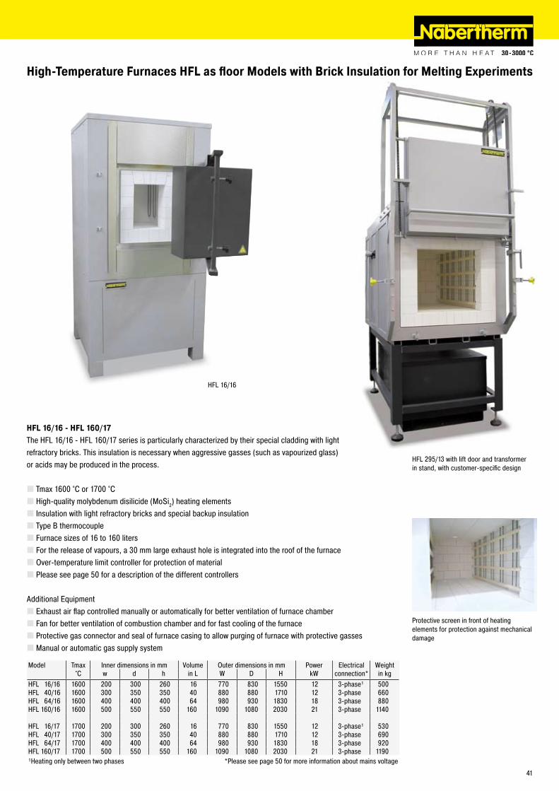
HFL 16/16
High-Temperature Furnaces HFL as floor Models with Brick Insulation for Melting Experiments
HFL 16/16 - HFL 160/17The HFL 16/16 - HFL 160/17 series is particularly characterized by their special cladding with light refractory bricks. This insulation is necessary when aggressive gasses (such as vapourized glass) or acids may be produced in the process.
Tmax 1600 °C or 1700 °CHigh-quality molybdenum disilicide (MoSi�) heating elementsInsulation with light refractory bricks and special backup insulationType B thermocoupleFurnace sizes of 16 to 160 litersFor the release of vapours, a 30 mm large exhaust hole is integrated into the roof of the furnaceOver-temperature limit controller for protection of materialPlease see page 50 for a description of the different controllers
Additional EquipmentExhaust air flap controlled manually or automatically for better ventilation of furnace chamberFan for better ventilation of combustion chamber and for fast cooling of the furnaceProtective gas connector and seal of furnace casing to allow purging of furnace with protective gassesManual or automatic gas supply system
HFL �95/13 with lift door and transformer in stand, with customer-specific design
Model Tmax Inner dimensions in mm Volume Outer dimensions in mm Power Electrical Weight°C w d h in L W D H kW connection* in kg
HFL 16/16 1600 �00 300 �60 16 770 830 1550 1� 3-phase¹ 500HFL 40/16 1600 300 350 350 40 880 880 1710 1� 3-phase 660HFL 64/16 1600 400 400 400 64 980 930 1830 18 3-phase 880HFL 160/16 1600 500 550 550 160 1090 1080 �030 �1 3-phase 1140
HFL 16/17 1700 �00 300 �60 16 770 830 1550 1� 3-phase¹ 530HFL 40/17 1700 300 350 350 40 880 880 1710 1� 3-phase 690HFL 64/17 1700 400 400 400 64 980 930 1830 18 3-phase 9�0HFL 160/17 1700 500 550 550 160 1090 1080 �030 �1 3-phase 1190¹Heating only between two phases *Please see page 50 for more information about mains voltage
Protective screen in front of heating elements for protection against mechanical damage
41
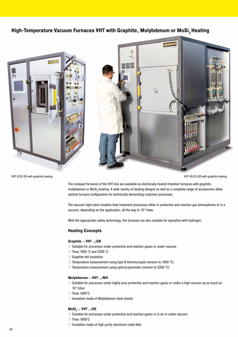
High-Temperature Vacuum Furnaces VHT with Graphite, Molybdenum or MoSi2 Heating
The compact furnaces of the VHT line are available as electrically heated chamber furnaces with graphite, molybdenum or MoSi� heating. A wide variety of heating designs as well as a complete range of accessories allow optimal furnace configuration for technically demanding customer processes.
The vacuum-tight retort enables heat treatment processes either in protective and reaction gas atmospheres or in a vacuum, depending on the application, all the way to 10-5 mbar.
With the appropriate safety technology, the furnaces are also suitable for operation with hydrogen.
Heating Concepts
Graphite – VHT ../GRSuitable for processes under protective and reaction gases or under vacuumTmax 1800 °C and ��00 °CGraphite felt insulationTemperature measurement using type B thermocouple (version to 1800 °C)Temperature measurement using optical pyrometer (version to ��00 °C)
Molybdenum – VHT ../MOSuitable for processes under highly pure protective and reaction gases or under a high vacuum up as much as 10-5 mbarTmax 1600°CInsulation made of Molybdenum steel sheets
MoSi2 – VHT ../KESuitable for processes under protective and reaction gases or in air or under vacuumTmax 1800°CInsulation made of high purity aluminum oxide fiber
VHT 40/��-GR with graphite heatingVHT 8/��-GR with graphite heating
4�
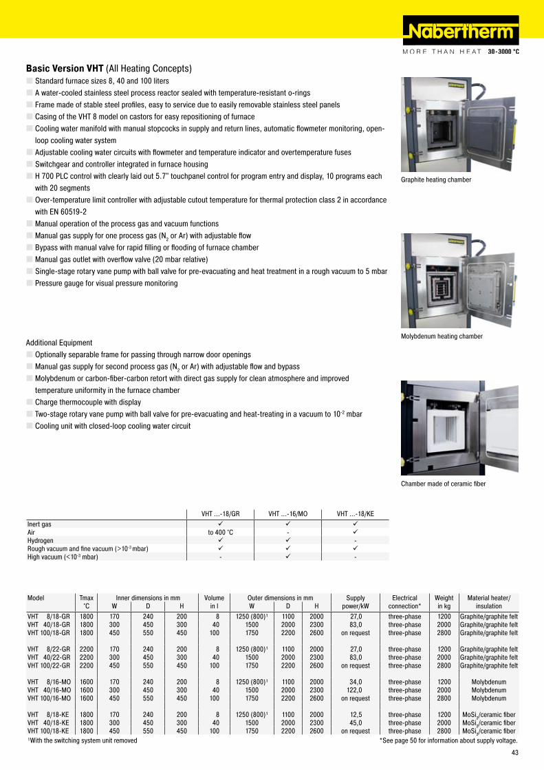
Basic Version VHT (All Heating Concepts)Standard furnace sizes 8, 40 and 100 litersA water-cooled stainless steel process reactor sealed with temperature-resistant o-ringsFrame made of stable steel profiles, easy to service due to easily removable stainless steel panelsCasing of the VHT 8 model on castors for easy repositioning of furnaceCooling water manifold with manual stopcocks in supply and return lines, automatic flowmeter monitoring, open-loop cooling water systemAdjustable cooling water circuits with flowmeter and temperature indicator and overtemperature fusesSwitchgear and controller integrated in furnace housingH 700 PLC control with clearly laid out 5.7" touchpanel control for program entry and display, 10 programs each with �0 segmentsOver-temperature limit controller with adjustable cutout temperature for thermal protection class � in accordance with EN 60519-�Manual operation of the process gas and vacuum functionsManual gas supply for one process gas (N� or Ar) with adjustable flowBypass with manual valve for rapid filling or flooding of furnace chamberManual gas outlet with overflow valve (�0 mbar relative)Single-stage rotary vane pump with ball valve for pre-evacuating and heat treatment in a rough vacuum to 5 mbarPressure gauge for visual pressure monitoring
Additional EquipmentOptionally separable frame for passing through narrow door openingsManual gas supply for second process gas (N� or Ar) with adjustable flow and bypassMolybdenum or carbon-fiber-carbon retort with direct gas supply for clean atmosphere and improved temperature uniformity in the furnace chamberCharge thermocouple with displayTwo-stage rotary vane pump with ball valve for pre-evacuating and heat-treating in a vacuum to 10-� mbarCooling unit with closed-loop cooling water circuit
Graphite heating chamber
VHT ...-18/GR VHT ...-16/MO VHT ...-18/KEInert gas Air to 400 °C - Hydrogen -Rough vacuum and fine vacuum (>10-3 mbar) High vacuum (<10-3 mbar) - -
Chamber made of ceramic fiber
Model Tmax Inner dimensions in mm Volume Outer dimensions in mm Supply Electrical Weight Material heater/°C W D H in l W D H power/kW connection* in kg insulation
VHT 8/18-GR 1800 170 �40 �00 8 1�50 (800)¹ 1100 �000 �7,0 three-phase 1�00 Graphite/graphite feltVHT 40/18-GR 1800 300 450 300 40 1500 �000 �300 83,0 three-phase �000 Graphite/graphite feltVHT 100/18-GR 1800 450 550 450 100 1750 ��00 �600 on request three-phase �800 Graphite/graphite felt
VHT 8/��-GR ��00 170 �40 �00 8 1�50 (800)¹ 1100 �000 �7,0 three-phase 1�00 Graphite/graphite feltVHT 40/��-GR ��00 300 450 300 40 1500 �000 �300 83,0 three-phase �000 Graphite/graphite feltVHT 100/��-GR ��00 450 550 450 100 1750 ��00 �600 on request three-phase �800 Graphite/graphite felt
VHT 8/16-MO 1600 170 �40 �00 8 1�50 (800)¹ 1100 �000 34,0 three-phase 1�00 MolybdenumVHT 40/16-MO 1600 300 450 300 40 1500 �000 �300 1��,0 three-phase �000 MolybdenumVHT 100/16-MO 1600 450 550 450 100 1750 ��00 �600 on request three-phase �800 Molybdenum
VHT 8/18-KE 1800 170 �40 �00 8 1�50 (800)¹ 1100 �000 1�,5 three-phase 1�00 MoSi�/ceramic fiberVHT 40/18-KE 1800 300 450 300 40 1500 �000 �300 45,0 three-phase �000 MoSi�/ceramic fiberVHT 100/18-KE 1800 450 550 450 100 1750 ��00 �600 on request three-phase �800 MoSi�/ceramic fiber¹With the switching system unit removed *See page 50 for information about supply voltage.
Molybdenum heating chamber
43
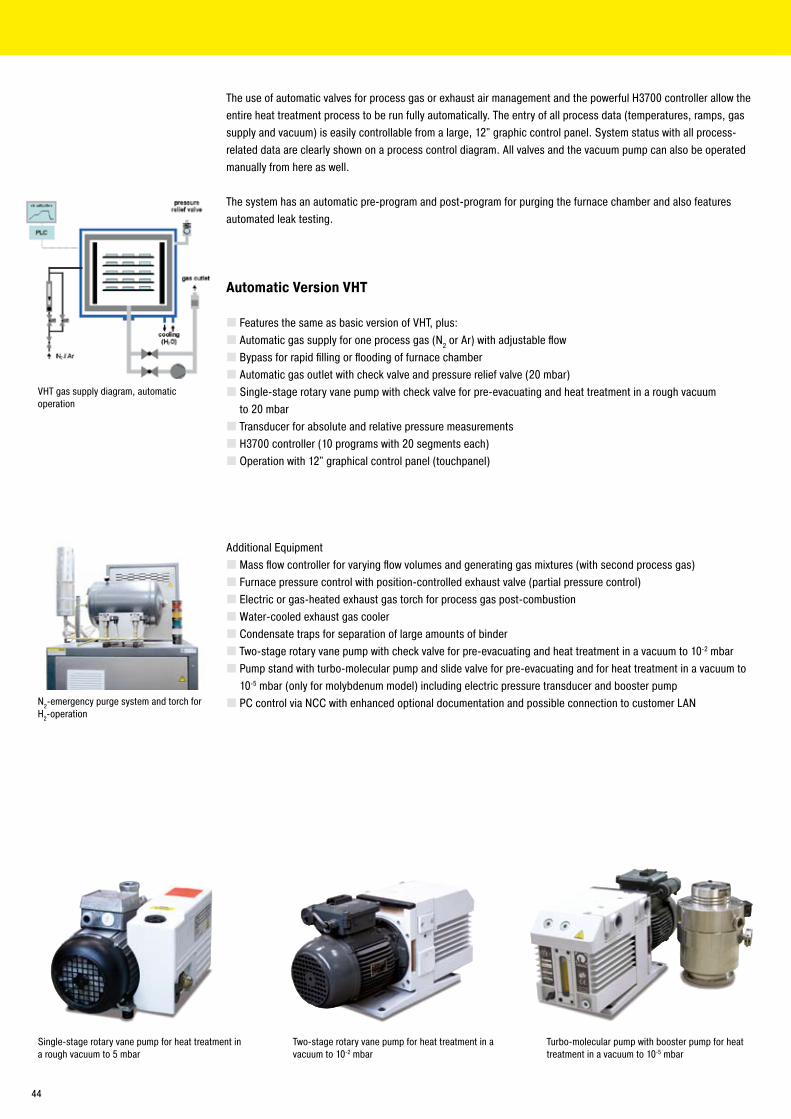
The use of automatic valves for process gas or exhaust air management and the powerful H3700 controller allow the entire heat treatment process to be run fully automatically. The entry of all process data (temperatures, ramps, gas supply and vacuum) is easily controllable from a large, 1�" graphic control panel. System status with all process-related data are clearly shown on a process control diagram. All valves and the vacuum pump can also be operated manually from here as well.
The system has an automatic pre-program and post-program for purging the furnace chamber and also features automated leak testing.
Automatic Version VHT
Features the same as basic version of VHT, plus:Automatic gas supply for one process gas (N� or Ar) with adjustable flowBypass for rapid filling or flooding of furnace chamberAutomatic gas outlet with check valve and pressure relief valve (�0 mbar)Single-stage rotary vane pump with check valve for pre-evacuating and heat treatment in a rough vacuum
to �0 mbarTransducer for absolute and relative pressure measurementsH3700 controller (10 programs with �0 segments each)Operation with 1�" graphical control panel (touchpanel)
Additional EquipmentMass flow controller for varying flow volumes and generating gas mixtures (with second process gas)Furnace pressure control with position-controlled exhaust valve (partial pressure control)Electric or gas-heated exhaust gas torch for process gas post-combustionWater-cooled exhaust gas coolerCondensate traps for separation of large amounts of binderTwo-stage rotary vane pump with check valve for pre-evacuating and heat treatment in a vacuum to 10-� mbarPump stand with turbo-molecular pump and slide valve for pre-evacuating and for heat treatment in a vacuum to 10-5 mbar (only for molybdenum model) including electric pressure transducer and booster pumpPC control via NCC with enhanced optional documentation and possible connection to customer LAN
Single-stage rotary vane pump for heat treatment in a rough vacuum to 5 mbar
VHT gas supply diagram, automatic operation
Two-stage rotary vane pump for heat treatment in a vacuum to 10-� mbar
Turbo-molecular pump with booster pump for heat treatment in a vacuum to 10-5 mbar
N�-emergency purge system and torch for H�-operation
44
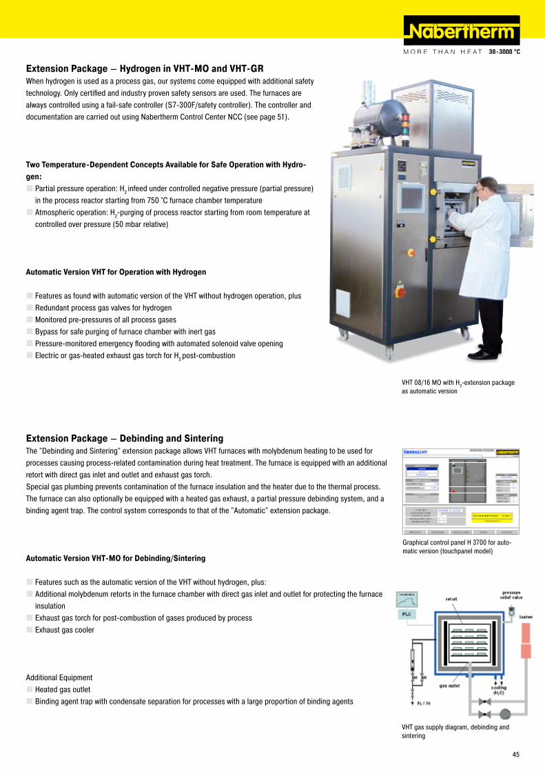
Extension Package – Hydrogen in VHT-MO and VHT-GRWhen hydrogen is used as a process gas, our systems come equipped with additional safety technology. Only certified and industry proven safety sensors are used. The furnaces are always controlled using a fail-safe controller (S7-300F/safety controller). The controller and documentation are carried out using Nabertherm Control Center NCC (see page 51).
Two Temperature-Dependent Concepts Available for Safe Operation with Hydro-gen:
Partial pressure operation: H� infeed under controlled negative pressure (partial pressure) in the process reactor starting from 750 °C furnace chamber temperatureAtmospheric operation: H�-purging of process reactor starting from room temperature at controlled over pressure (50 mbar relative)
Automatic Version VHT for Operation with Hydrogen
Features as found with automatic version of the VHT without hydrogen operation, plusRedundant process gas valves for hydrogenMonitored pre-pressures of all process gasesBypass for safe purging of furnace chamber with inert gasPressure-monitored emergency flooding with automated solenoid valve openingElectric or gas-heated exhaust gas torch for H� post-combustion
Extension Package – Debinding and SinteringThe "Debinding and Sintering" extension package allows VHT furnaces with molybdenum heating to be used for processes causing process-related contamination during heat treatment. The furnace is equipped with an additional retort with direct gas inlet and outlet and exhaust gas torch.Special gas plumbing prevents contamination of the furnace insulation and the heater due to the thermal process. The furnace can also optionally be equipped with a heated gas exhaust, a partial pressure debinding system, and a binding agent trap. The control system corresponds to that of the "Automatic" extension package.
Automatic Version VHT-MO for Debinding/Sintering
Features such as the automatic version of the VHT without hydrogen, plus:Additional molybdenum retorts in the furnace chamber with direct gas inlet and outlet for protecting the furnace insulationExhaust gas torch for post-combustion of gases produced by processExhaust gas cooler
Additional EquipmentHeated gas outletBinding agent trap with condensate separation for processes with a large proportion of binding agents
VHT gas supply diagram, debinding and sintering
Graphical control panel H 3700 for auto-matic version (touchpanel model)
VHT 08/16 MO with H�-extension package as automatic version
45
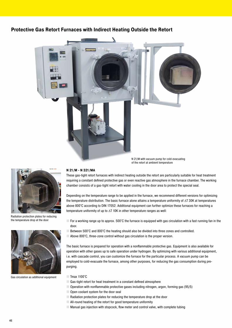
Protective Gas Retort Furnaces with Indirect Heating Outside the Retort
N 21/M - N 321/MAThese gas-tight retort furnaces with indirect heating outside the retort are particularly suitable for heat treatment requiring a constant defined protective gas or even reactive gas atmosphere in the furnace chamber. The working chamber consists of a gas-tight retort with water cooling in the door area to protect the special seal.
Depending on the temperature range to be applied in the furnace, we recommend different versions for optimizing the temperature distribution. The basic furnace alone attains a temperature uniformity of ΔT 30K at temperatures above 800°C according to DIN 1705�. Additional equipment can further optimize these furnaces for reaching a temperature uniformity of up to ΔT 10K in other temperature ranges as well:
For a working range up to approx. 500°C the furnace is equipped with gas circulation with a fast running fan in the door.Between 500°C and 800°C the heating should also be divided into three zones and controlled.Above 800°C, three-zone control without gas circulation is the proper version.
The basic furnace is prepared for operation with a nonflammable protective gas. Equipment is also available for operation with other gases up to safe operation under hydrogen. By optimizing with various additional equipment, i.e. with cascade control, you can customize the furnace for the particular process. A vacuum pump can be employed to cold-evacuate the furnace, among other purposes, for reducing the gas consumption during pre-purging.
Tmax 1100°CGas-tight retort for heat treatment in a constant defined atmosphereOperation with nonflammable protective gases including nitrogen, argon, forming gas (95/5)Open coolant system for the door sealRadiation protection plates for reducing the temperature drop at the doorAll-round heating of the retort for good temperature uniformityManual gas injection with stopcock, flow meter and control valve, with complete tubing
N �1/M with vacuum pump for cold-evacuating of the retort at ambient temperature
Radiation protection plates for reducing the temperature drop at the door
Gas circulation as additional equipment
46
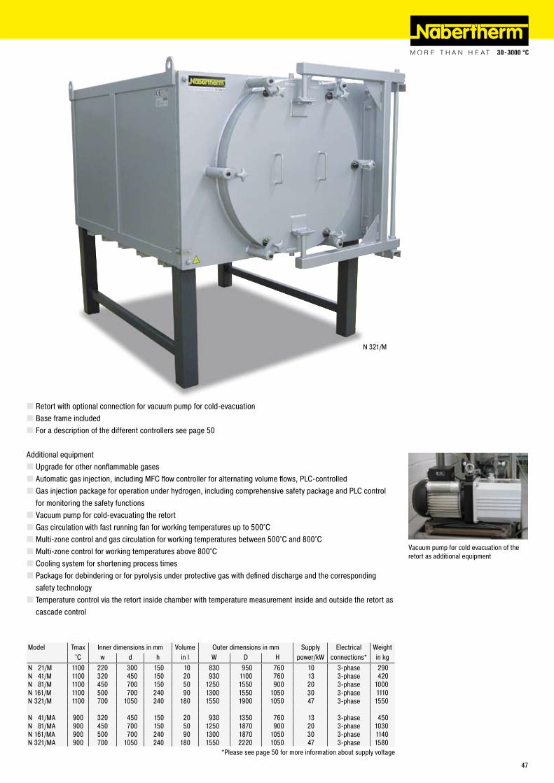
N 3�1/M
Retort with optional connection for vacuum pump for cold-evacuationBase frame includedFor a description of the different controllers see page 50
Additional equipmentUpgrade for other nonflammable gasesAutomatic gas injection, including MFC flow controller for alternating volume flows, PLC-controlledGas injection package for operation under hydrogen, including comprehensive safety package and PLC control for monitoring the safety functionsVacuum pump for cold-evacuating the retortGas circulation with fast running fan for working temperatures up to 500°CMulti-zone control and gas circulation for working temperatures between 500°C and 800°CMulti-zone control for working temperatures above 800°CCooling system for shortening process timesPackage for debindering or for pyrolysis under protective gas with defined discharge and the corresponding safety technologyTemperature control via the retort inside chamber with temperature measurement inside and outside the retort as cascade control
Vacuum pump for cold evacuation of the retort as additional equipment
Model Tmax Inner dimensions in mm Volume Outer dimensions in mm Supply Electrical Weight°C w d h in l W D H power/kW connections* in kg
N �1/M 1100 ��0 300 150 10 830 950 760 10 3-phase �90N 41/M 1100 3�0 450 150 �0 930 1100 760 13 3-phase 4�0N 81/M 1100 450 700 150 50 1�50 1550 900 �0 3-phase 1000N 161/M 1100 500 700 �40 90 1300 1550 1050 30 3-phase 1110N 3�1/M 1100 700 1050 �40 180 1550 1900 1050 47 3-phase 1550
N 41/MA 900 3�0 450 150 �0 930 1350 760 13 3-phase 450N 81/MA 900 450 700 150 50 1�50 1870 900 �0 3-phase 1030N 161/MA 900 500 700 �40 90 1300 1870 1050 30 3-phase 1140N 3�1/MA 900 700 1050 �40 180 1550 ���0 1050 47 3-phase 1580
*Please see page 50 for more information about supply voltage
47
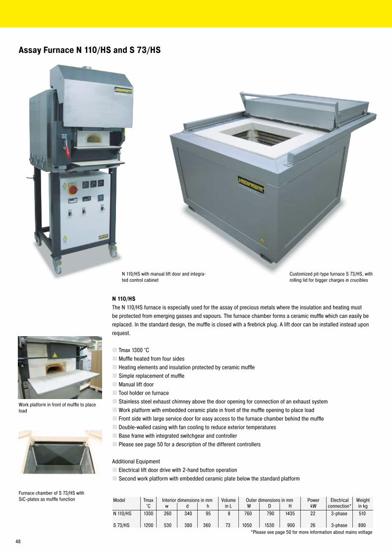
N 110/HSThe N 110/HS furnace is especially used for the assay of precious metals where the insulation and heating must be protected from emerging gasses and vapours. The furnace chamber forms a ceramic muffle which can easily be replaced. In the standard design, the muffle is closed with a firebrick plug. A lift door can be installed instead upon request.
Tmax 1300 °CMuffle heated from four sidesHeating elements and insulation protected by ceramic muffleSimple replacement of muffleManual lift doorTool holder on furnaceStainless steel exhaust chimney above the door opening for connection of an exhaust systemWork platform with embedded ceramic plate in front of the muffle opening to place loadFront side with large service door for easy access to the furnace chamber behind the muffleDouble-walled casing with fan cooling to reduce exterior temperaturesBase frame with integrated switchgear and controllerPlease see page 50 for a description of the different controllers
Additional EquipmentElectrical lift door drive with �-hand button operationSecond work platform with embedded ceramic plate below the standard platform
N 110/HS with manual lift door and integra-ted control cabinet
Assay Furnace N 110/HS and S 73/HS
Model Tmax Interior dimensions in mm Volume Outer dimensions in mm Power Electrical Weight°C w d h in L W D H kW connection* in kg
N 110/HS 1300 �60 340 95 8 760 790 1435 �� 3-phase 510
S 73/HS 1�00 530 380 360 73 1050 1530 900 �6 3-phase 890*Please see page 50 for more information about mains voltage
Work platform in front of muffle to place load
Customized pit-type furnace S 73/HS, with rolling lid for bigger charges in crucibles
Furnace chamber of S 73/HS with SiC-plates as muffle function
48
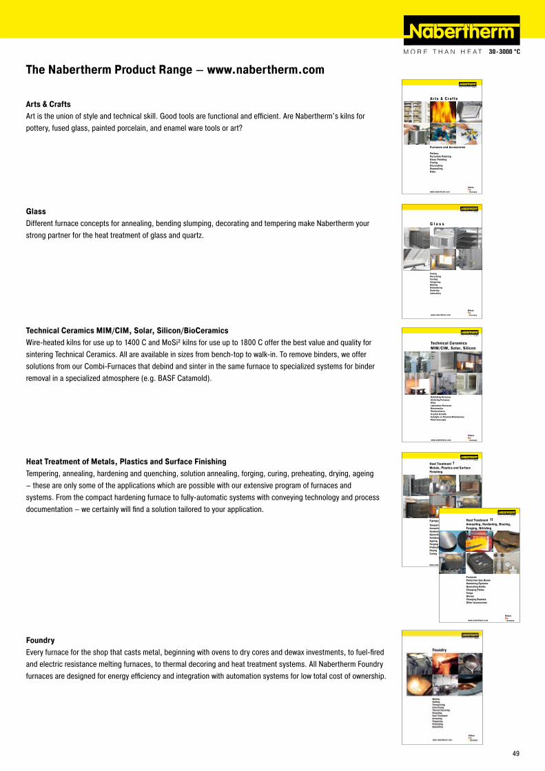
www.nabertherm.com
MadeinGermany
Technical CeramicsMIM/CIM, Solar, Silicon
Debinding FurnacesSintering FurnacesKilnsLaboratory Furnaces BioceramicsPhotovoltaicsCrystal GrowthCatalytic or Thermal AfterburnersPlant Concepts
www.nabertherm.com
Madein Germany
Ar ts & Craf ts
Furnaces and Accessories
PotteryPorcelain PaintingGlass PaintingFusingDecoratingEnamellingRaku
www.nabertherm.com
Madein Germany
Heat Treatment Metals, Plastics and Surface Finishing
Furnaces and Systems for Tempering AnnealingHardeningQuenchingSolution AnnealingAgeingForgingPreheatingDryingCuring
www.nabertherm.com
MadeinGermany
FurnacesProtective Gas BoxesHardening SystemsQuenching BathsCharging PlatesTongsGlovesCharging BasketsOther Accessories
Heat TreatmentAnnealing, Hardening, Brazing, Forging, Nitriding
The Nabertherm Product Range – www.nabertherm.com
Arts & CraftsArt is the union of style and technical skill. Good tools are functional and efficient. Are Nabertherm's kilns for pottery, fused glass, painted porcelain, and enamel ware tools or art?
GlassDifferent furnace concepts for annealing, bending slumping, decorating and tempering make Nabertherm your strong partner for the heat treatment of glass and quartz.
Technical Ceramics MIM/CIM, Solar, Silicon/BioCeramicsWire-heated kilns for use up to 1400 C and MoSi² kilns for use up to 1800 C offer the best value and quality for sintering Technical Ceramics. All are available in sizes from bench-top to walk-in. To remove binders, we offer solutions from our Combi-Furnaces that debind and sinter in the same furnace to specialized systems for binder removal in a specialized atmosphere (e.g. BASF Catamold).
Heat Treatment of Metals, Plastics and Surface FinishingTempering, annealing, hardening and quenching, solution annealing, forging, curing, preheating, drying, ageing – these are only some of the applications which are possible with our extensive program of furnaces and systems. From the compact hardening furnace to fully-automatic systems with conveying technology and process documentation – we certainly will find a solution tailored to your application.
FoundryEvery furnace for the shop that casts metal, beginning with ovens to dry cores and dewax investments, to fuel-fired and electric resistance melting furnaces, to thermal decoring and heat treatment systems. All Nabertherm Foundry furnaces are designed for energy efficiency and integration with automation systems for low total cost of ownership.
49
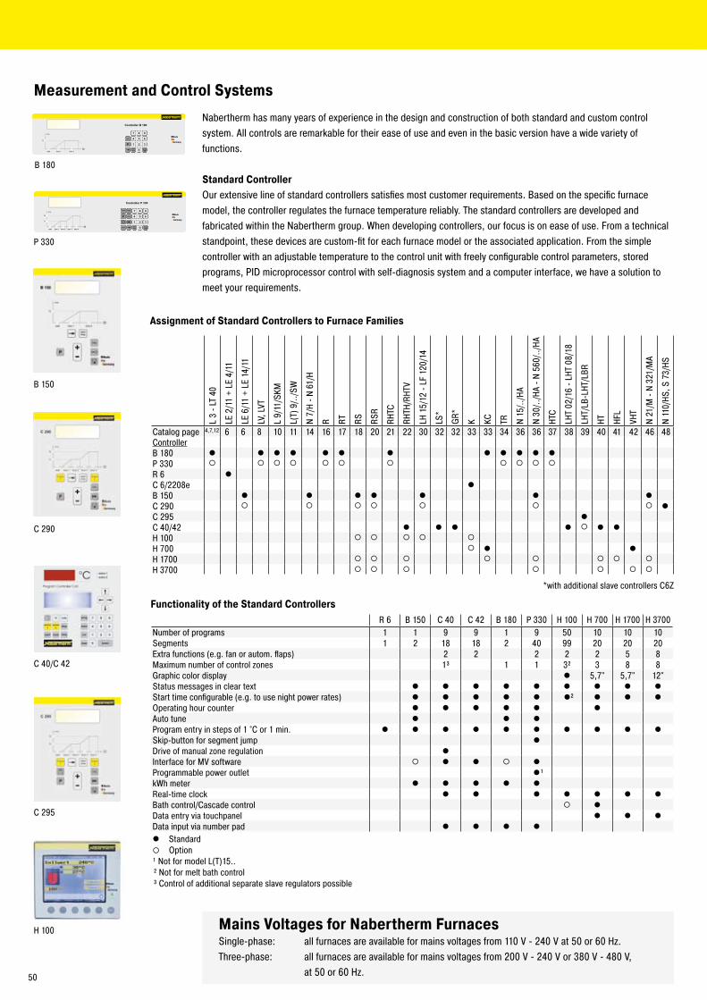
B 180
P 330
C �90
H 100
B 150
C �95
C 40/C 4�
Measurement and Control Systems
Nabertherm has many years of experience in the design and construction of both standard and custom control system. All controls are remarkable for their ease of use and even in the basic version have a wide variety of functions.
Standard ControllerOur extensive line of standard controllers satisfies most customer requirements. Based on the specific furnace model, the controller regulates the furnace temperature reliably. The standard controllers are developed and fabricated within the Nabertherm group. When developing controllers, our focus is on ease of use. From a technical standpoint, these devices are custom-fit for each furnace model or the associated application. From the simple controller with an adjustable temperature to the control unit with freely configurable control parameters, stored programs, PID microprocessor control with self-diagnosis system and a computer interface, we have a solution to meet your requirements.
Assignment of Standard Controllers to Furnace Families
Mains Voltages for Nabertherm FurnacesSingle-phase: all furnaces are available for mains voltages from 110 V - �40 V at 50 or 60 Hz.Three-phase: all furnaces are available for mains voltages from �00 V - �40 V or 380 V - 480 V, at 50 or 60 Hz.
*with additional slave controllers C6Z
L 3
- LT
40
LE �
/11
+ LE
4/1
1
LE 6
/11
+ LE
14/
11
LV, L
VT
L 9/
11/S
KM
L(T)
9/..
/SW
N 7/
H - N
61/
H
R RT RS RSR
RHTC
RHTH
/RHT
V
LH 1
5/1�
- LF
1�0
/14
LS*
GR*
K KC TR N 15
/../H
A
N 30
/../H
A - N
560
/../H
A
HTC
LHT
0�/1
6 - L
HT 0
8/18
LHT/
LB-L
HT/L
BR
HT HFL
VHT
N �1
/M -
N 3�
1/M
A
N 11
0/HS
, S 7
3/HS
Catalog page 4,7,1� 6 6 8 10 11 14 16 17 18 �0 �1 �� 30 3� 3� 33 33 34 36 36 37 38 39 40 41 4� 46 48ControllerB 180 l l l l l l l l l l l lP 330 ¡ ¡ ¡ ¡ ¡ ¡ ¡ ¡ ¡ ¡ ¡
R 6 lC 6/��08e lB 150 l l l l l l lC �90 ¡ ¡ ¡ ¡ ¡ ¡ ¡ lC �95 lC 40/4� l l l l ¡ l lH 100 ¡ ¡ ¡ ¡ ¡
H 700 ¡ l lH 1700 ¡ ¡ ¡ ¡ ¡ ¡ ¡ ¡
H 3700 ¡ ¡ ¡ ¡ ¡ ¡ ¡
Functionality of the Standard ControllersR 6 B 150 C 40 C 4� B 180 P 330 H 100 H 700 H 1700 H 3700
Number of programs 1 1 9 9 1 9 50 10 10 10Segments 1 � 18 18 � 40 99 �0 �0 �0Extra functions (e.g. fan or autom. flaps) � � � � � 5 8Maximum number of control zones 1³ 1 1 3² 3 8 8Graphic color display l 5,7" 5,7" 1�"Status messages in clear text l l l l l l l l lStart time configurable (e.g. to use night power rates) l l l l l l² l l lOperating hour counter l l l l l lAuto tune l l lProgram entry in steps of 1 °C or 1 min. l l l l l l l l l lSkip-button for segment jump lDrive of manual zone regulation lInterface for MV software ¡ l l ¡ lProgrammable power outlet l¹kWh meter l l l l lReal-time clock l l l l l l lBath control/Cascade control ¡ lData entry via touchpanel l l lData input via number pad l l l ll Standard¡ Option¹ Not for model L(T)15..² Not for melt bath control³ Control of additional separate slave regulators possible
50
Professional Control and Documentation Alternatives
H 3700 with colored graphic presentation of data
Control Center NCC user interface display-ed on a PC
H 1700 with colored, tabular depiction of the data
Graphic printer
HiProSystems Control and DocumentationThis professional control system for single and multi-zone furnaces is based on Siemens hardware and can be adapted and upgraded extensively. HiProSystems control is used when more than two process-dependent functions, such as exhaust dampers, cooling fans, automatic movements, etc., have to be handled during a cycle; when furnaces with more than one zone have to be controlled; when special documentation of each batch is required and when remote telediagnostic service is required. The system is also perfectly suited for controlling multiple furnaces or furnace groups. It is flexible and is easily tailored to your process or documentation needs.
Alternative User InterfacesTouch panel H 700This basic panel accommodates most basic needs and is very easy to use.Touch panel H 1700Firing cycle data and the extra functions activated are clearly displayed in a table. Messages appear as text.Touch panel H 3700All functions and process data are stored and displayed in easy to read charts. The data can be exported through various interfaces (RS �3�, RS 4�� /485, USB, Ethernet TCI/IP, MPI, Profibus) to a local PC or your company network for further processing. A CF card also gives the opportunity for data storage and transfer to a PC with a card reader.Extension Package, PC-based for Control, Visualisation and Documentation Nabertherm Control Center NCCUpgrading the HiProSystems-Control individually into an NCC provides for additional interfaces, operating documentation, and service benefits in particular for controlling furnace groups including charge beyond the furnace itself (quenching tank, cooling station etc.):
Recommended for heat treatment processes with extensive requirements in respect to documentation e.g. for metals, technical ceramics or in the medicine fieldSoftware can be used also in accordance with the AMS 2750 D (NADCAP)Documentation according to the requirements of Food and Drug Administration (FDA), Part 11, EGV 164�/03 possibleCharge data can be read in via barcodesInterface for connection to existing Enterprise Database systems (e.g. SAP, Oracle)Connection to mobile phone network for alarm message transmission via SMSControl from various locations over the networkCalibration of each measuring point for a specific temperature possibleExtendable for calibration of a polygonal line with up to 18 temperatures per measuring point for use at different temperatures e.g for AMS �750 D applications
Controltherm MV Software for Monitoring, Documentation and Control with Standard Con-trollersDocumentation and reproducibility gain increased attention with steadily rising quality standards.The powerful Nabertherm software Controltherm MV provides for an optimum solution for the control anddocumentation of one or more furnaces (furnace data only).
FeaturesSimple installation without specific knowledgeAll Nabertherm controllers with interface connectableTemperature cycles of up to 16 furnaces (also multi-zone controlled) can be archived in manipulation-safe filesRedundant storage on a network server possibleProgramming, archiving and printing of programs and graphicsFree input of descriptive charge data text with comfortable search functionData exportable into Excel format for further evaluationStart/stop of the controller from the local PC400 additional programs storable (only with Nabertherm controllers)Connection of other furnaces/controllers by means of an additional temperature transducer possible and retrofittableExtension of additional measuring points for archiving possible and retrofittable
*not possible in combination with temperature transducer
Temperature RecorderReliable documentation method with a dot printer or continuous pen and up to six measuring points, also availablewith digitally storing graphic printer (e.g. CF card, USB-stick).
51
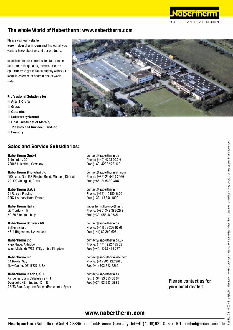
Headquarters: Nabertherm GmbH . �8865 Lilienthal/Bremen, Germany . Tel +49 (4�98) 9��-0 . Fax -101 . [email protected]
www.nabertherm.com
Please visit our website www.nabertherm.com and find out all you want to know about us and our products.
In addition to our current calendar of trade fairs and training dates, there is also the opportunity to get in touch directly with your local sales office or nearest dealer world-wide.
Professional Solutions for:Arts & CraftsGlassCeramicsLaboratory/DentalHeat Treatment of Metals,
Plastics and Surface FinishingFoundry
The whole World of Nabertherm: www.nabertherm.com
Reg
No. C
5.1
0/09
.08
(eng
lisch
), in
form
atio
n he
rein
is s
ubje
ct to
cha
nge
with
out n
otic
e. N
aber
ther
m a
ssum
es n
o lia
bilit
y fo
r any
erro
rs th
at m
ay a
ppea
r in
this
doc
umen
t.
[email protected]: (+49) 4�98 9��-0Fax: (+49) 4�98 9��-1�9
[email protected]: (+86) �1 6490 �960Fax: (+86) �1 6490 3107
[email protected]: (+33) 1 5356 1800Fax: (+33) 1 5356 1809
[email protected]: (+39) 348 38�0�78Fax: (+39) 055 480835
[email protected]: (+41) 6� �09 6070Fax: (+41) 6� �09 6071
[email protected]: (+44) 19�� 455 5�1Fax: (+44) 19�� 455 �77
[email protected]: (+1) 30� 3�� 3665Fax: (+1) 30� 3�� 3�15
[email protected].: (+34) 93 553 08 87Fax: (+34) 93 583 95 85
Sales and Service Subsidiaries:
Nabertherm GmbHBahnhofstr. �0�8865 Lilienthal, Germany
Nabertherm Shanghai Ltd.150 Lane, No. 158 Pingbei Road, Minhang District�01109 Shanghai, China
Nabertherm S.A.S51 Rue de Presles93531 Aubervilliers, France
Nabertherm Italiavia Trento N° 1750139 Florence, Italy
Nabertherm Schweiz AG Batterieweg 64614 Hägendorf, Switzerland
Nabertherm Ltd.Vigo Place, AldridgeWest Midlands WS9 8YB, United Kingdom
Nabertherm Inc.54 Reads WayNew Castle, DE 197�0, USA
Nabertherm Ibérica, S.L.Av. de les Corts Catalanes 9 - 11Despacho 4E - Entidad 1� - 1308173 Sant Cugat del Vallés (Barcelona), Spain
Please contact us for your local dealer!