laboratory determination of hydraulic anisotropy of dense ... · el concreto asfáltico de...
TRANSCRIPT
67
IngenIería e InvestIgacIón vol. 38 n.° 1, aprIl - 2017 (67-73)
Laboratory determination of hydraulic anisotropy of dense graded asphalt concrete
Determinación en laboratorio de la anisotropía hidráulica del concreto asfáltico de granulometría continua
Alberto Gaxiola-Hernández1, Alexandra Ossa-López2, Jorge Luis Almaral-Sánchez3, and Omar Llanes-Cárdenas4
ABSTRACT
Dense graded asphalt concrete is widely used in roads as support structure for vehicle loads. However, it is also used for hydraulic purposes in canal linings as well as faces and cores of dams. In the design stage of these constructions, it is necessary to have the permeability data of the materials that will be used and, although in some cases it is sufficient to know this parameter in only one direction, in others it is necessary to have it in two directions. The parameter that indicates the ratio of the permeability coefficients between the axial and transverse direction is known as hydraulic anisotropy (A). There are studies that estimate A in asphalt concrete, however, there is no standard procedure to determine these results in the laboratory. This research presents test results of axial permeability in constant head permeameter and the design of a radial permeability test device in asphalt concrete made for hydraulic purposes. As a result, it was determined that the compaction process of asphalt concrete, applied in one direction, causes the material to have anisotropic behavior from the hydraulic point of view, resulting in anisotropy ratios from 7.1 to 10.4, for the studied asphalt mixture. This research is of paramount importance for engineers who design hydraulic structures of asphalt concrete since it provides them with a simple laboratory procedure to determine the hydraulic anisotropy of this material.
Keywords: Asphalt concrete, radial permeability, anisotropy.
RESUMEN
El concreto asfáltico de granulometría continua es utilizado ampliamente en carreteras como estructura de soporte de cargas vehiculares, sin embargo, también es utilizado con propósitos hidráulicos en revestimientos de canales así como en caras y núcleos de presas. En la etapa del diseño de estas obras es necesario contar con los datos de permeabilidad de los materiales con los que serán construidas y aunque en algunos casos es suficiente conocer este parámetro en una sola dirección, en otros es necesario determinarlo en dos direcciones. Al parámetro que indica la relación de los coeficientes de permeabilidad entre las direcciones axial y transversal se le conoce como anisotropía hidráulica (A). Existen estudios que estiman A en el concreto asfáltico, sin embargo, no se dispone de un procedimiento estándar que determine estos resultados en el laboratorio. Esta investigación muestra los resultados de pruebas de permeabilidad axial en permeámetro de carga constante y el desarrollo de un dispositivo de prueba de permeabilidad radial en concreto asfáltico elaborado con propósitos hidráulicos. Como resultado de esta investigación se determinó que el proceso de compactación del concreto asfáltico, dado en una dirección, provoca que el material tenga un comportamiento anisótropo desde el punto de vista hidráulico, obteniendo una relación de anisotropía de entre 7.1 y 10.4, para la mezcla asfáltica estudiada. Esta investigación es de gran utilidad para los ingenieros que diseñan estructuras hidráulicas de concreto asfáltico ya que se pone a su disposición un procedimiento de laboratorio sencillo para determinar la anisotropía hidráulica de este material.
Palabras clave: Concreto asfáltico, permeabilidad radial, anisotropía.
Received: August 20th 2017Accepted: January 10th 2018
DOI: http://dx.doi.org/10.15446/ing.investig.v38n1.67166
How to cite: Gaxiola-Hernández, A., Ossa-López, A., Almaral-Sánchez, J. L., and Llanes-Cárdenas, O. (2018). Laboratory determination of hydraulic anisotropy of dense graded asphalt concrete. Ingeniería e Investigación, 38(1), 67-73. DOI: 10.15446/ing.investig.v38n1.67166
Attribution 4.0 International (CC BY 4.0) Share - Adapt
Introduction
Asphalt concrete has been widely used as building material, mainly in road construction and, to a lesser extent, in impermeable barriers. Although different types of asphalt concrete have been used for the construction of hydraulic barriers, including within these structures the dam cores, dam faces and canal linings (USSD, 2011), (USBR, 1976), the most widely used is the dense graded asphalt concrete. This is according to the International
1 Ph.D. (c) in Civil Engineering, Instituto de Ingeniería, Universidad Nacional Autónoma de México, México. M. Ing. in road ways. Universidad Autónoma de Sinaloa, México. E-mail: [email protected]
2 Ph.D. and M. Ing. in Civil Engineering, Instituto de Ingeniería, Universidad Nacional Autónoma de México, México. E-mail: [email protected]
3 Ph.D., CINVESTAV, Instituto Politécnico Nacional., M. Ing. Civil. Universidad Autónoma de Sinaloa, México. E-mail: [email protected]. *Corresponding Author
4 Ph.D., M.Sc., Instituto Politécnico Nacional, México. E-mail: [email protected]
Laboratory determination of hydrauLic anisotropy of dense graded asphaLt concrete
IngenIería e InvestIgacIón vol. 38 n.° 1, aprIl - 2018 (67-73)68
Commission on Large Dams, which presents in its bulletin 84 (ICOLD, 1992) a detailed report on this type of dams built up to its publication date. In these structures, it is of supreme importance to know the hydraulic conductivity of the materials from which it will be formed, and, for this purpose, tests are carried out to determine its permeability coefficient (k).
Permeability studies usually present the values of k obtained in a single direction. In many applications and with certain materials, this may be sufficient and correct (Li, Kayhanian, & Harvey, 2013; Mallick, Cooley, Teto, Bradbury, & Peabody, 2003). However, when the hydraulic behavior of a material is very different in one direction than in another. Presenting the permeability coefficient in a single direction can lead to estimating behaviors in the structure that are far from reality (Aniskin & Memarianfard, 2012; Jing, Zhang, Thimm, & Zepp, 2008). In the case of asphalt concrete, this is an artificial material prepared in the field and in the laboratory applying the compaction process in one direction; this can lead to a distribution of the components in which the air voids are not disposed in the same way in all directions (Aboufoul & García, 2017).
The parameter used to determine these flow differences is known as the degree of hydraulic anisotropy (A) and is defined as the ratio of the hydraulic conductivity considering the flow in two directions. The anisotropy in the section of a single layer is defined by the ratio of the permeability coefficient parallel to the direction of laying (kx) and normal to the layer (kz), given by Equation (1) (Assouline & Or, 2006). Petersen (Petersen, Trautner, & Hansen, 2008) found A values up to 38 in soils, while Masad et al. (2007) carried out a simulation of the three-dimensional flow in which they determined these values in asphalt concrete that led to find degrees of anisotropy up to 11,00.
A= kxkz
(1)
When the water passes through a porous medium where the flow is laminar, the well-known Darcy’s law given by Equation (2) is fulfilled, where U is the discharge velocity, k is the permeability coefficient and i is the hydraulic gradient.
U = ki (2)
However, when the pores within the medium are sufficiently wide the flow is not laminar and moves away from this condition as the pore size increases. To modelize the cases where the flow into the porous medium is not laminar, there are different equations, Border & Zimmer (2000) (Bordier & Zimmer, 2000) summarize these equations and show, among them, Equation (3), where N and λ are coefficients that depend on the flow.
U N =λN i (3)
If both members of Equation (2) are raised to the power of 1/N, Equation (4) is obtained, whereas equation (5) is obtained by replacing the parameter 1/N by n and the parameter λ by k. This latter equation expresses that, when the flow within a porous medium is laminar, discharge velocity is proportional to hydraulic gradient, whereas, when this flow condition is not present, the discharge velocity will be proportional to in.
U =λi1/N (4)
U = kin (5)
Tan et al. (2000) indicate that n from Equation (5) could have values ranging from 0,5 to 1,0 when the flow is turbulent or laminar, respectively. It should be noted that Equation (5) converges to Darcy’s law as exponent n approaches 1,0.
In tests made on asphalt concrete by Waters (1990), it can be noted that when the discharge velocity is greater, the coefficient n, in fact, tends to 0,5. This value approaches notably 1,0 when the discharge velocity decreases. This is consistent with the statements made by Umiliaco and Benedetto (2013), who mentioned that Darcy’s law is fulfilled only when water moves at very low velocities.
To record the permeability coefficient in a single direction, axial flow permeameter is generally used, with fairly well-known methods. However, there is no standard test method available to obtain this parameter in another direction. In this sense, this study uses the results of radial flow permeability tests, in a device designed for this specific purpose.
Materials and methodology
To determine the permeability coefficient of asphalt concrete, specimens 15 cm in diameter and 20 cm in height were prepared, to which a core was later drilled, resulting finally in cylinders with 10 cm in diameter. Next, the characterization of asphalt binder and mineral aggregate used to conduct the axial permeability tests in a constant head permeameter and radial permeability with convergent flow in a device specially designed for this test is presented.
Materials
Asphalt concrete specimens were prepared using basaltic mineral aggregate, whose characteristics are described in Tables 1 and 2, in which the results of origin and consensus tests performed on the material are shown. Regarding asphalt binder, according to AASHTO M 320, its designation is PG 64-22, of which a content (Pb ) of 6,0 % with respect to the total mass of the mixture was used. Table 3 presents the results of characterization tests performed on asphalt.
IngenIería e InvestIgacIón vol. 38 n.° 1, aprIl - 2018 (67-73) 69
GAXIOLA-HERNÁNDEZ, OSSA-LÓPEZ, ALMARAL-SÁNCHEZ, AND LLANES-CÁRDENAS
Table 1. Mineral aggregate characterization
ASTM Method Result
Water absorption (%) C 127 and C 128 1.61
Resistance to degradation, Los Angeles machine (%)
C 131 16
Soundness by sodium sulfate (%)
C 88 1
Fractured particles (%) D 5821 100
Uncompacted void content of fine aggregate (%)
C 1252 42
Sand equivalent value (%) D 2419 64
Source: Authors
Table 2. Density and absorption of coarse aggregate
Grain sizeGsb Gsss Gsa
Water absorption
(%)
ASTM Method
in mm
1/2” 12,5 2,608 2,649 2,270 1,586 C 127
3/8” 9,5 2,613 2,654 2,726 1,586 C 127
1/4” 6,3 2,608 2,653 2,729 1,691 C 127
# 4 4,75 2,602 2,647 2,723 1,697 C 128
Gsb= Bulk specific gravityGsss= Saturated surface dry specific gravityGsa= Apparent specific gravitySource: Authors
Table 3. Asphalt binder characterization
ASTM Method Result
Rotational viscosity at 135 °C (cP) D4402 488
Flash point (°C) D92 318
Dynamic shear modulus of the original asphalt (kPa)
D7175 1,44
Mass loss by heating (%) D2872 0,536
Dynamic shear modulus after RTFO (kPa)
D7175 5,91
Dynamic shear modulus after PAV (kPa) D7175 3307
Slope of the stiffness curve m D6648 0,3
Creep Stiffness S (MPa) D6648 135
Source: Authors
For the preparation of asphalt concrete, special attention must be paid to determining the grain size distribution, since this influences the hydraulic conductivity (Abdullah, Obaidat, & Abu-Sa’da, 1998; Umiliaco & Benedetto, 2013). According to the recommendations of Höeg (1993) and ICOLD (1982) in which it is suggested to use Fuller’s curve to elaborate impervious asphalt concrete, in this study, a cylinder using this grain size distribution to batch the mixture, which was later tested with a permeameter using axial flow was initially prepared. From this experiment, it turned out that, even with a hydraulic head of up to 7,0 kg/cm2, no water flow was recorded while maintaining the pressure applied for a period of up to 24 hours. To obtain water flow records, three mixtures with different gradations and with increasing air-
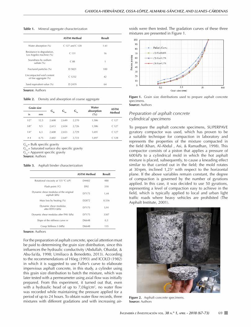
voids were then tested. The gradation curves of these three mixtures are presented in Figure 1.
Figure 1. Grain size distributions used to prepare asphalt concrete specimens.Source: Authors
Preparation of asphalt concrete cylindrical specimens
To prepare the asphalt concrete specimens, SUPERPAVE gyratory compactor was used, which has proven to be a suitable technique for compaction in laboratory and represents the properties of the mixture compacted in the field (Khan, Al-Abdul , Asi, & Ramadhan, 1998). This compactor consists of a piston that applies a pressure of 600 kPa to a cylindrical mold in which the hot asphalt mixture is placed, subsequently, to cause a kneading effect similar to that carried out in the field; the mold rotates at 30 rpm, inclined 1,25o with respect to the horizontal plane. If the above variables remain constant, the degree of compaction is governed by the number of gyrations applied. In this case, it was decided to use 50 gyrations, representing a level of compaction easy to achieve in the field, which is typically applied to local and urban light traffic roads where heavy vehicles are prohibited (The Asphalt Institute, 2001).
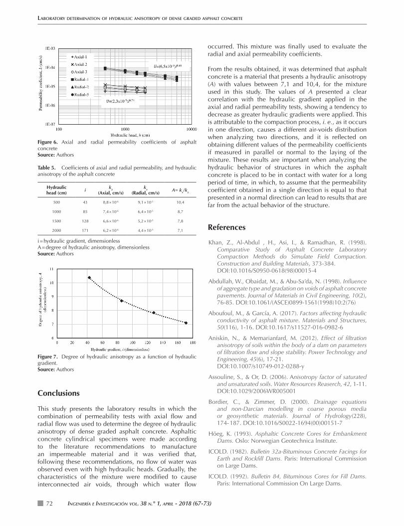
Figure 2. Asphalt concrete specimens.Source: Authors

Laboratory determination of hydrauLic anisotropy of dense graded asphaLt concrete
IngenIería e InvestIgacIón vol. 38 n.° 1, aprIl - 2018 (67-73)70
Initially, the cylindrical specimen prepared using Fuller’s curve as a gradation and tested in the axial permeameter did not show water flows, even with a low compaction degree and high hydraulic head. After this, the decision was made on modifying the characteristics of the mixture until it was possible to obtain flow records. The variable chosen for this was the grain size distribution, since the degree of compaction and asphalt content were already low. Thus, different curves were considered in order to increase the air-void content, keeping the rest of the variables constant. With Fuller’s curve, it was possible to elaborate asphalt concrete with an air void content of 0,5 %; with curves 1 and 2, air-voids of 0,8 and 1.2 % were achieved, respectively. The mixture that allowed water flow was prepared with curve 3 (see Figure 1), i. e., with this mixture the air-voids showed end-to-end connections. Finally, with this last grain size distribution, six cylinders with the same characteristics of compaction and asphalt content were elaborated, three of them to conduct axial permeability tests and the rest to be used in the radial permeability tests. Volumetric characteristics are presented in Table 4.
Table 4. Volumetric characteristics of the asphalt concrete used in the permeability tests
ASTM Method Result
Maximum specific gravity, Gmm D2041 2,427
Voids in the mineral aggregate, VMA (%)
D1188 14,7
Voids filled with asphalt, VFA (%) D1188 88,1
Volume of air voids, Va (%) D2872 1,7
Source: Authors
Figure 2 shows a specimen 15 cm in diameter and 20 cm in height; the 10 cm core drilled and the 2,5 cm height central-part-of-the-cylinder with which the tests of axial flow permeability were carried out.
Axial permeability tests
To obtain the axial hydraulic conductivity, a constant-head with flexible-wall permeameter was used. A photograph of it is presented in Figure 3. Hydraulic heads ranging from 0,1 to 7,0 kg/cm2 were applied, at the same time, the flow through the test tubes were recorded to define their permeability coefficient. This permeameter has a data acquisition system that is made up of an interface between the measuring devices and a computer in which data is recorded and processed by means of a software.
The permeameter has a clear acrylic chamber, with a head and a base connected to pipes to cause the water to flow inside the asphalt concrete specimens and to control the imposed pressures. These specimens are placed in the middle of these two pieces with a latex membrane that allows to control the cell pressure applied while, at the same time, the hydraulic head that is applied both in the top and in bottom of the specimen is controlled.
Figure 3. Asphalt concrete specimen in a permeameter with axial flow.Source: Authors
Design and performance of radial permeability tests
To obtain the permeability coefficient of asphalt concrete in a direction other than the axial direction, radial flow permeability tests were performed to specimens with characteristics similar to those used in axial flow tests, using a binder content of 6,0 % and the curve 3 as gradation (Figure 1). With this goal, a device was designed to measure radial permeability to cylinders of asphalt concrete in which a cell pressure was applied. The water that entered radially to the specimen and then flowed out through the connected tube at the top of it was measured.
To each of the asphalt concrete specimens 20 cm high and 10 cm in diameter, a hole was drilled in the center of the cylinder, with 2,7 cm in diameter and 14 cm in depth, in which a rubber stopper was placed and a tube inserted in order to collect and measure the water flow. The portions of the specimen where the flow entering the perforation could be in some way different from radial, were waterproofed using epoxy resin. Figure 4 shows a schematic with the dimensions of the specimens prepared for the radial permeability test.
Based on Darcy’s law, an expression was obtained to estimate the radial permeability coefficient (k) of an asphalt concrete cylinder, depending on the flow velocity (v) and the hydraulic gradient (i), as indicated in Equations (6) to (10).
v= k i (6)
The hydraulic gradient of Equation (6), expressed in differential form as a function of hydraulic head (h) and radius (r) is:
i= dhdr
(7)
Considering that the velocity of water is the ratio between outflow rate (Q) and the area through which flows, the

IngenIería e InvestIgacIón vol. 38 n.° 1, aprIl - 2018 (67-73) 71
GAXIOLA-HERNÁNDEZ, OSSA-LÓPEZ, ALMARAL-SÁNCHEZ, AND LLANES-CÁRDENAS
Equation (7) was substituted in Equation (6) and the following expression was obtained:
Q= k 2πrh( ) dhdr
(8)
Integrating Equation (8) results in Equation (9):
Q
2kπhri
re
∫drr=
hi
he
∫ dh (9)
Finally, radial permeability coefficient is calculated with Equation (10), where k is the permeability coefficient, in cm/s; Q is the flow rate at the output of the device, in cm3/s; re is the radius of the asphalt concrete specimen, in cm; ri is the radius of the hole drilled to the center of the specimen, in cm; he is the hydraulic head (cell pressure), in cm; hi is the hydraulic head into the drilled hole, in cm and, finally, L is the height of the portion of the cylinder remaining free from epoxy resin, by which the water enters the inside of the drilled hole, in cm.
k =
Qln reri
⎛
⎝⎜⎜⎜⎜
⎞
⎠⎟⎟⎟⎟
2kL he−hi( ) (10)
Cell pressures heads (he) of 500, 1 000, 1 500, 2 000, 4 000 and 6 000 cm were applied. The cell pressure head of 6 000 cm is the maximum pressure that the acrylic chamber can safely support. A dam with a height of about 60 m undergoes this hydraulic pressure. For each of the heads, the outflow volume and the elapsed time were measured. These data allowed to calculate the outflow rate (Q) and, finally, obtain the permeability coefficient using Equation (10). This procedure was performed for three asphalt concrete specimens with similar volumetric characteristics.
Figure 4. Asphalt concrete specimen prepared for radial permeability tests.Source: Authors
After preparing the specimens, they were placed in a water-filled acrylic chamber similar to those used in triaxial compression tests, as shown in Figure 5. In this figure, the tube connecting the cylinder with the outside of the pressure chamber can be observed. This tube is connected to a valve in which the outflow that determines the permeability coefficient is measured.
Figure 5. Device used to measure radial permeability.Source: Authors
Results
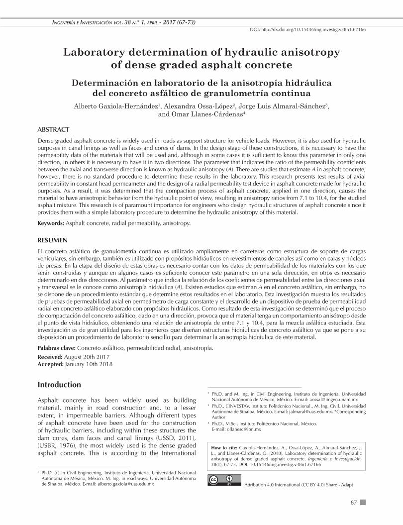
After conducting the tests of axial permeability in flexible wall permeameter and radial permeability in the specially designed device, the results are illustrated in Figure 6. In this figure, it is clear that the values of the permeability coefficient obtained radially are clearly higher than those obtained axially, which indicates a hydraulic anisotropy.
Based on the data above, the average permeability coefficient corresponding to each of the hydraulic head was obtained, for both types of test used. Special attention should be paid to the equation of correlation U = (2,3×10⁻⁵)i 0.74 for axial flow permeability tests and U=(6,5×10⁻⁴)i 0.48 for radial flow permeability tests (see Figure 6). If the power of these equations were near to 1,0, laminar flow condition could be assumed. However, the values of n = 0,74 and n = 0,48 indicate that, for this particular experiment, the most appropriate model is Equation (5). These data are presented in Table 5, where A values from 7,1 to 10,4 are observed, for the mixture and the values of the hydraulic gradient used in this study, with a tendency to decrease as the hydraulic gradient increases (see Figure 7).
Laboratory determination of hydrauLic anisotropy of dense graded asphaLt concrete
IngenIería e InvestIgacIón vol. 38 n.° 1, aprIl - 2018 (67-73)72
Figure 6. Axial and radial permeability coefficients of asphalt concrete Source: Authors
Table 5. Coefficients of axial and radial permeability, and hydraulic anisotropy of the asphalt concrete
Hydraulic head (cm)
ikz
(Axial, cm/s)kx
(Radial, cm/s)A= kx/kz
500 43 8,8 × 10⁻⁶ 9,1 × 10⁻⁵ 10,4
1000 85 7,4 × 10⁻⁶ 6,4 × 10⁻⁵ 8,7
1500 128 6,6 × 10⁻⁶ 5,2 × 10⁻⁵ 7,8
2000 171 6,2 × 10⁻⁶ 4,4 × 10⁻⁵ 7,1
i = hydraulic gradient, dimensionless A = degree of hydraulic anisotropy, dimensionlessSource: Authors
occurred. This mixture was finally used to evaluate the radial and axial permeability coefficients.
From the results obtained, it was determined that asphalt concrete is a material that presents a hydraulic anisotropy (A) with values between 7,1 and 10,4, for the mixture used in this study. The values of A presented a clear correlation with the hydraulic gradient applied in the axial and radial permeability tests, showing a tendency to decrease as greater hydraulic gradients were applied. This is attributable to the compaction process, i. e., as it occurs in one direction, causes a different air-voids distribution when analyzing two directions, and it is reflected on obtaining different values of the permeability coefficients if measured in parallel or normal to the laying of the mixture. These results are important when analyzing the hydraulic behavior of structures in which the asphalt concrete is placed to be in contact with water for a long period of time, in which, to assume that the permeability coefficient obtained in a single direction is equal to that presented in a normal direction can lead to results that are far from the actual behavior of the structure.
References
Khan, Z., Al-Abdul , H., Asi, I., & Ramadhan, R. (1998). Comparative Study of Asphalt Concrete Laboratory Compaction Methods do Simulate Field Compaction. Construction and Building Materials, 373-384.
DOI:10.1016/S0950-0618(98)00015-4
Abdullah, W., Obaidat, M., & Abu-Sa’da, N. (1998). Influence of aggregate type and gradation on voids of asphalt concrete pavements. Journal of Materials in Civil Engineering, 10(2), 76-85. DOI:10.1061/(ASCE)0899-1561(1998)10:2(76)
Aboufoul, M., & García, A. (2017). Factors affecting hydraulic conductivity of asphalt mixture. Materials and Structures, 50(116), 1-16. DOI:10.1617/s11527-016-0982-6
Aniskin, N., & Memarianfard, M. (2012). Effect of filtration anisotropy of soils within the body of a dam on parameters of filtration flow and slope stability. Power Technology and Engineering, 45(6), 17-21.
DOI:10.1007/s10749-012-0288-y
Assouline, S., & Or, D. (2006). Anisotropy factor of saturated and unsaturated soils. Water Resources Reaserch, 42, 1-11. DOI:10.1029/2006WR005001
Bordier, C., & Zimmer, D. (2000). Drainage equations and non-Darcian modelling in coarse porous media or geosynthetic materials. Journal of Hydrology(228), 174- 187. DOI:10.1016/S0022-1694(00)00151-7
Höeg, K. (1993). Asphaltic Concrete Cores for Embankment Dams. Oslo: Norwegian Geotechnica lnstitute.
ICOLD. (1982). Bulletin 32a-Bituminous Concrete Facings for Earth and Rockfill Dams. Paris: International Commission on Large Dams.
ICOLD. (1992). Bulletin 84, Bituminous Cores for Fill Dams. Paris: International Commission On Large Dams.
Figure 7. Degree of hydraulic anisotropy as a function of hydraulic gradient.Source: Authors
Conclusions
This study presents the laboratory results in which the combination of permeability tests with axial flow and radial flow was used to determine the degree of hydraulic anisotropy of dense graded asphalt concrete. Asphaltic concrete cylindrical specimens were made according to the literature recommendations to manufacture an impermeable material and it was verified that, following these recommendations, no flow of water was observed even with high hydraulic heads. Gradually, the characteristics of the mixture were modified to cause interconnected air voids, through which water flow

IngenIería e InvestIgacIón vol. 38 n.° 1, aprIl - 2018 (67-73) 73
GAXIOLA-HERNÁNDEZ, OSSA-LÓPEZ, ALMARAL-SÁNCHEZ, AND LLANES-CÁRDENAS
Jing , Y.-S., Zhang, B., Thimm, A., & Zepp, H. (2008). Anisotropy of Soil Hydraulic Properties Along Arable Slopes. Pedosphere, 18(3), 353-362.
DOI:10.1016/S1002-0160(08)60025-9
Li, H., Kayhanian, M., & Harvey, J. (2013). Comparative field permeability measurement of permeable pavements using ASTM C1701 and NCAT permeameter methods. Journal of Environmental Management, 118, 144-152.
DOI:10.1016/j.jenvman.2013.01.016
Mallick, R., Cooley, A., Teto, M., Bradbury, R., & Peabody, D. (2003). NCAT Report 003-02 An evaluation of factors affecting permeability of SUPERPAVE designed pavements. Auburn, Al.: National Center for Asphalt Technology.
Masad, E., Al Omari, A., & Chen, H.-C. (2007). Computations of permeability tensor coefficients and anisotropy of asphalt concrete based on microstructure simulation of fluid flow. Computational Materials Science, 40, 449-459. DOI:10.1016/j.commatsci.2007.01.015
Petersen, C., Trautner, A., & Hansen, S. (2008). Spatio-temporal variation of anisotropy of saturated hydraulic conductivity in a tilled sandy loam soil. Soil & Tillage Research, 100, 108-113. DOI:10.1016/j.still.2008.05.004
Tan, S., Fwa, T., & Guwe, Y. (2000). New Apparatus for Measuring the Drainage Properties of Unbond Aggregates. Proceedings of the Fifth International Symposium on Unbond Aggregates in Roads. Pp. 63-67. Nottingham. UK.
The Asphalt Institute. (2001). Superpave Mix Design, Third Edition.
Umiliaco, A., & Benedetto, A. (2013). Aggregate size distribution and hydraulic permeability of HMA: a full simulation study. Airfield and Highway Pavement 2013: Sustainable and Efficient Pavements, 1134-1144. DOI:10.1061/9780784413005.095
USBR. (1976). Lininga for irrigation canals (First Edition ed.). Washington: USA Bureau of Reclamation.
USSD. (2011). Materials for Embankment Dams. U. S. Society on Dams.
Waters, T. (1990). A Study of Infiltration Properties of Road Surface Materials. M. App. Thesis. Queensland University of Technology, Australia.