laboratory exercise 1: open channel ow...
TRANSCRIPT

Chapter 1
Laboratory exercise 1: Open channel
flow measurement
Laboratory exercise Open channel flow measurement is placed on the Faculty of Civil and Geode-
tic Engineering, on Department of Environmental Civil Engineering (Hydraulic Department) at
Hajdrihova street 28, 1000 Ljubljana.
Figure 1.1: Directions from Faculty of Mechanical Eng. (Askerceva 6) to Department of Envi-
ronmental Civil Eng. (Hajdrihova 28).
1.1 Introduction
Flow measurement is the quantification of bulk fluid movement and can be measured in a variety
of ways. When dealing with liquids, flows can be divided between open-channel flows and pipe
flows. Free surface flow can be always found in open-channel flows and also in some cases in
1

CHAPTER 1. LABORATORY EXERCISE 1: OPEN CHANNEL FLOW MEASUREMENT2
pipe flows.
Figure 1.2: A: pipe flow, B: pipe flow (free surface), C: open channel flow.
1.1.1 Flow measurement
Most common flowmeters for pipe flow are differential pressure flowmeters (orifice plates, flow
nozzles, Venturi tubes and rotameters), turbine flowmeters, electromagnetic flowmeters...
By open channel flows all the upper mentioned flowmeters are not appropriate, that is why
other methods must be used. A common method of measuring flow through an open channel
is to measure the height of the liquid as it passes over an obstruction as a flume or weir in the
channel.
Most common types of weirs are broad-crested (rectangular) and sharp-crested (rectangular,
triangular and trapezoidal). Sharp-crested weirs are usually used to measure the discharge of
smaller rivers and channel, while broad-crested weirs are usually used to measure the discharge
of larger rivers and canals.
Figure 1.3: Common sharp-crested weir shapes.
CHAPTER 1. LABORATORY EXERCISE 1: OPEN CHANNEL FLOW MEASUREMENT3
1.1.2 Thomson V-notch
The Thomson V-notch provides a simple and reliable way of measuring water flow. The method
is particularly suitable for measuring flows in contaminated water, for example in sedimentation
basins. The V-notch, sharp-crested weir is especially good for measuring low flow rates.
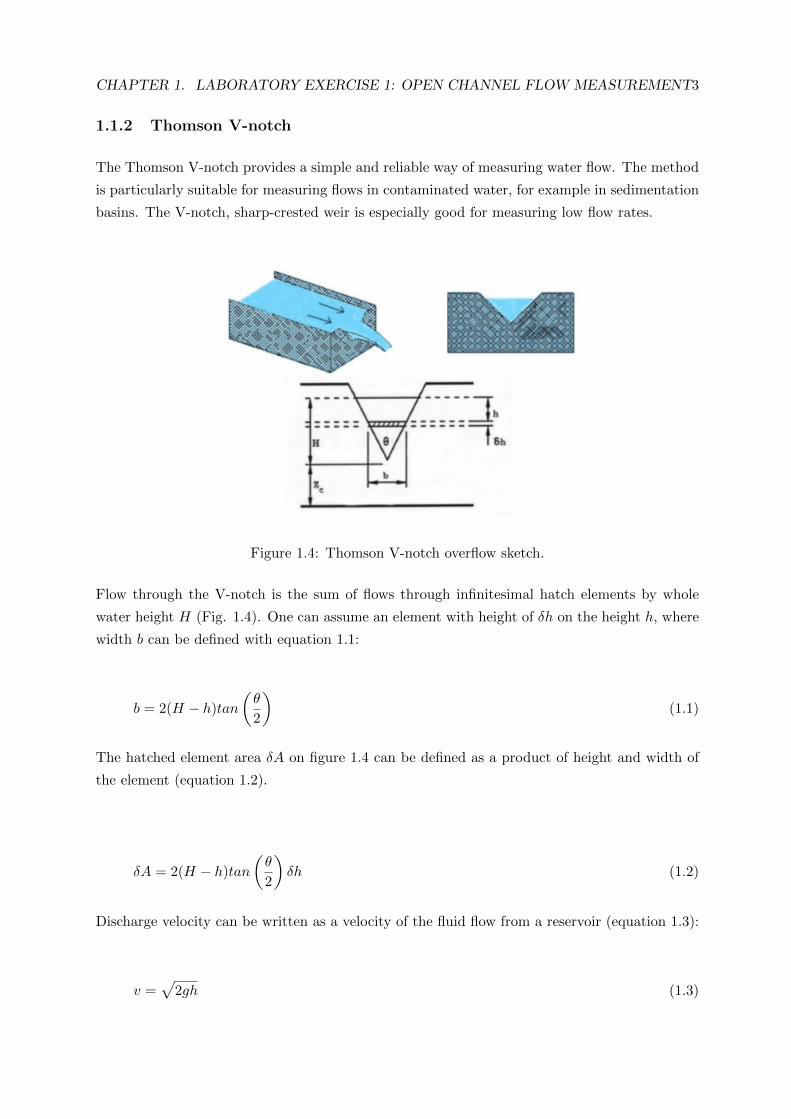
Figure 1.4: Thomson V-notch overflow sketch.
Flow through the V-notch is the sum of flows through infinitesimal hatch elements by whole
water height H (Fig. 1.4). One can assume an element with height of δh on the height h, where
width b can be defined with equation 1.1:
b = 2(H − h)tan
(θ
2
)(1.1)
The hatched element area δA on figure 1.4 can be defined as a product of height and width of
the element (equation 1.2).
δA = 2(H − h)tan
(θ
2
)δh (1.2)
Discharge velocity can be written as a velocity of the fluid flow from a reservoir (equation 1.3):
v =√
2gh (1.3)

CHAPTER 1. LABORATORY EXERCISE 1: OPEN CHANNEL FLOW MEASUREMENT4
Flow through the infinitesimal element of the overflow can be written as a product of it’s surface
and velocity (equation 1.4):
δQ = 2(H − h)tan
(θ
2
)√2gh · δh (1.4)
If one integrate the equation 1.4 between h = 0 and h = H, the following expression comes to
place (equation 1.5):
Q = 2tan
(θ
2
)√2g
∫ H
0
[Hh1/2 − h3/2
]dh =
2tan
(θ
2
)√2g
[2
3H5/2 − 2
5H5/2
]=
8
15tan
(θ
2
)√2gH5/2
(1.5)
Theoretically calculated flow is not the same as the actual flow, thus a correction coefficient Cd
is used and the final expression is written as (equation 1.6):
Q = Cd8
15tan
(θ
2
)√2gH5/2 (1.6)
For the V-notch used in the laboratory, the coefficient can be read from a poster placed on the
wall in the laboratory (Fig. 1.5).
Figure 1.5: Thomson V-notch correction coefficient.

CHAPTER 1. LABORATORY EXERCISE 1: OPEN CHANNEL FLOW MEASUREMENT5
1.2 Experimental set-up
Experimental set-up (Fig. 1.6) is placed in the Laboratory for Fluid Mechanics. Figure 1.6 shows
Thomson V-notch, placed in the stainless steel open reservoir. Reservoirs in the laboratory are
used for several different experimental set-ups, that is why one must considered which valves
must be closed and which open to achive flow through the Thomson reservoir. The complete
experimental set-up (Fig. 1.7) contains a main large resevoir (60 m3) in the basement, from
which water is pumped into the upper overflow resevoir, from the upper overflow reservoir it
flows into the lower overflow reservoir, which height position can be manualy set. These two
overflow reservoirs also serve as flow settlers. From the lower overflow reservoir the water flows
through the surge reservoir into the last reservoir, where the Thomson V-notch weir is placed.
After the water passes through the weir, it flows back to the main reservoir into the basement.
The pump which is used to maintain the flow through the station is placed in the basement and
can be controlled by the frequency controller placed in the laboratory.
For succesull measurements one must ensure constant flow through the Thomson V-notch weir,
that means that water level in the lower overflow reservoir must be high enough to ensure, that
part of the flow goes directly back to the main reservoir.
For the reference value of the flow rate an electromagnetic flowmeter is installed before the surge
reservoir. To measure the flowrate by the V-notch weir the height of the water level is needed,
which can be measured by different measurement methods. For the laboratory exercise one can
use ultrasonic level measurement device, a pressure transducer or a regular hand ruler.
Figure 1.6: Experimental set-up image.

CHAPTER 1. LABORATORY EXERCISE 1: OPEN CHANNEL FLOW MEASUREMENT6
Figure 1.7: Experimental scheme.
1.3 Student task list
1. Connect all the necessary data acquisition equipment,
2. Chose ten working points,
3. Measure the height of the water surface, with at least two measuring methods,
4. Compare experimental data H(Q) with theoretical H(Q) curve (Fig. 1.5),
5. Draw a scheme of the experimental set-up,
6. Write a report about the laboratory exercise. Comments about the measurements and the
results must be included.
1.3.1 Additional work
For grade 10, student can perform the following tasks:
• Describe at least two additional measuring methods for flow measurements in open chan-
nels.
• Compare the described methods with the Thomson V-notch weir method.
Additional work can contain maximum 3 A4 pages of material.