laboratory of general and inorganic chemistry department...
TRANSCRIPT

WORKSHOP
X-ray crystallographyDubravka Matković-Čalogović
Laboratory of General and Inorganic ChemistryDepartment of ChemistryFaculty of ScienceUniversity of Zagreb, Croatia

Crystal
A crystal or crystalline solid is a solid material, whose constituent atoms, molecules, or ions are arranged in an orderly repeating pattern extending in all three spatial dimensions.
Symmetry is one of the mainproperties of crystals.
Angles between the faces areconstant.
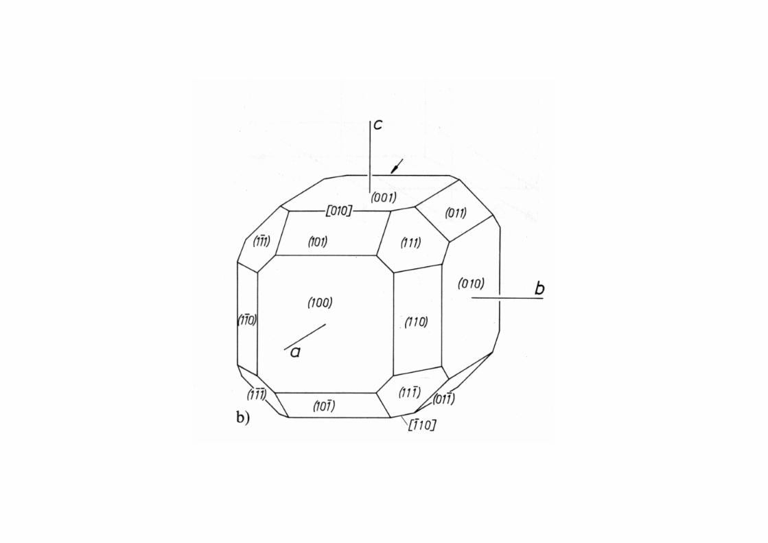
Miller indices are used to describe crystal faces.
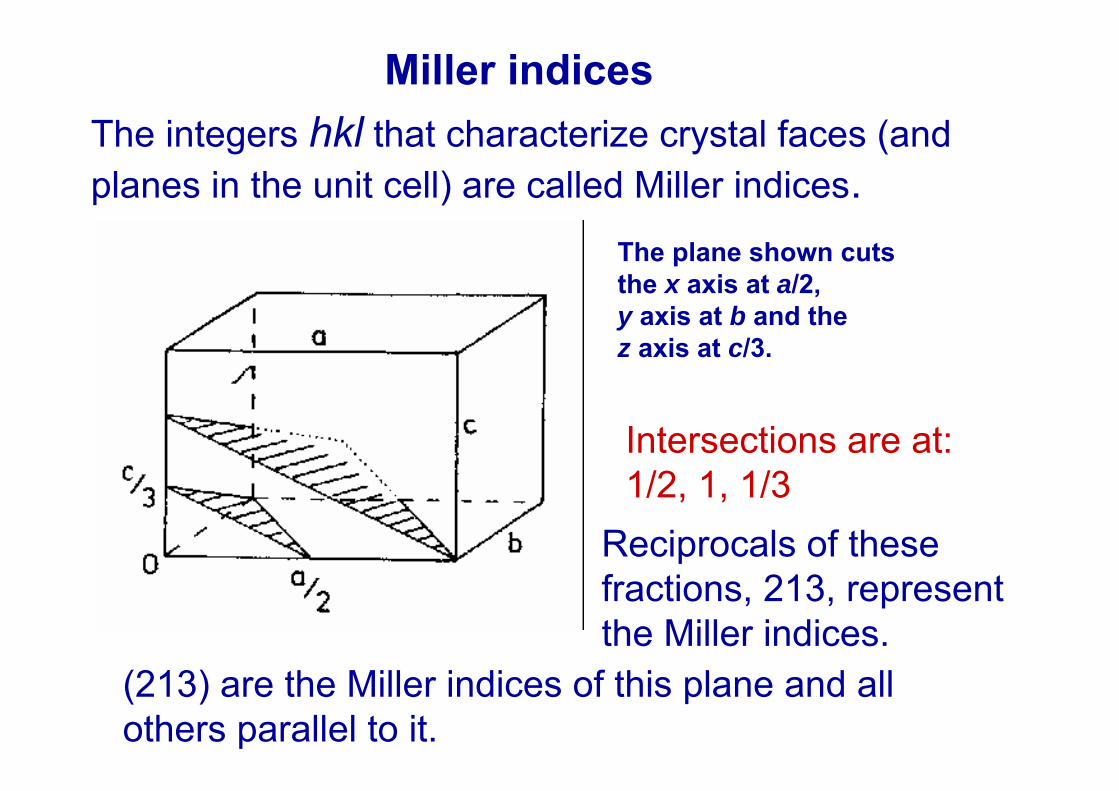
Miller indicesThe integers hkl that characterize crystal faces (andplanes in the unit cell) are called Miller indices.
The plane shown cutsthe x axis at a/2,y axis at b and thez axis at c/3.
Intersections are at:1/2, 1, 1/3
Reciprocals of these fractions, 213, representthe Miller indices.
(213) are the Miller indices of this plane and all others parallel to it.

a) (101) b) (010)
c) (200) d) (h00)
e) hexagonal unit cell
f) (hkil), (-12-10)
i = -(h + k)

a
b
c
Triclinic a b c
90o
Monoclinic a b c
= = 90o 90o
Orthorhombic a b c
= = = 90o
Tetragonal a = b c
= = = 90o
Trigonal a = b = c
= = 90o
Hexagonal a = b c
= = 90o = 120o
Cubic a = b = c
= = = 90o
7 crystal systems

Lattice centering (includes translation)
P (primitive) x, y, z
C (centered on the (001) faces) x, y, z x+1/2, y+1/2, z
I (body centered) x, y, z x+1/2, y+1/2, z+1/2
F (face centered) x, y, z x+1/2, y+1/2, zx+1/2, y, z+1/2 x, y+1/2, z+1/2
R (rhombohedral) x, y, z x+1/3, y+2/3, z+2/3x+2/3, y+1/3, z+1/3

Triclinic Monoclinic Orthorhombic
Hexagonal P & Trigonal P, RTetragonal
Cubic
14 Bravais lattices

• Rotation axes• Inversion axes
32 Point groups
Symmetry in crystals

2 ( m) converts an_
Mirror plane symmetryobject (a molecule) into its mirror image.
z
x, y, z x, -y, z

When translation is added new symmetryoperations are obtained:
screw axes (rotation axes combined with translation)21 31 32 41 42 43 61 62 63 64 65
glide planes (reflection bymirror planes combined with translation)a b c n d
x, y, z x+1/2, -y, -zPicture shows 21 parallel to a; themolecule is translated by a/2

230 space groups
are obtained by combining:
32 point groups14 Bravais latticesscrew axesglide planes

Escher’s drawing


Unit cell is the smallest repeating unit which shows the full symmetry of the crystal structure

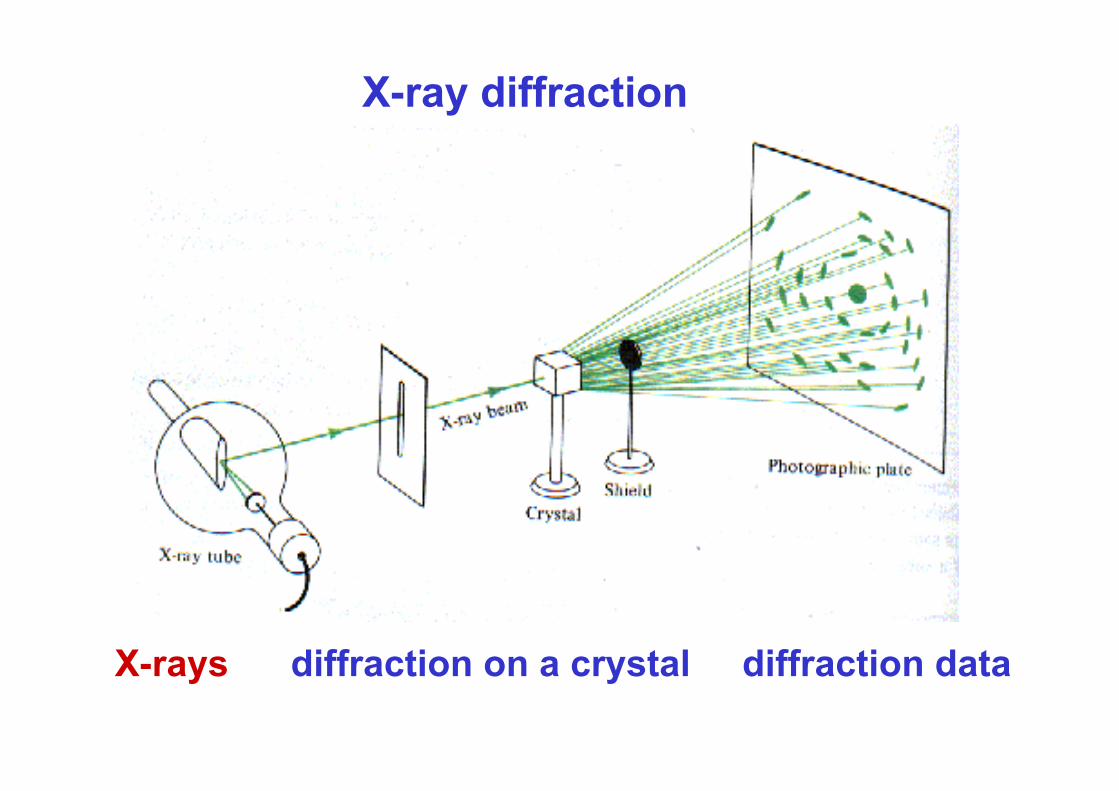
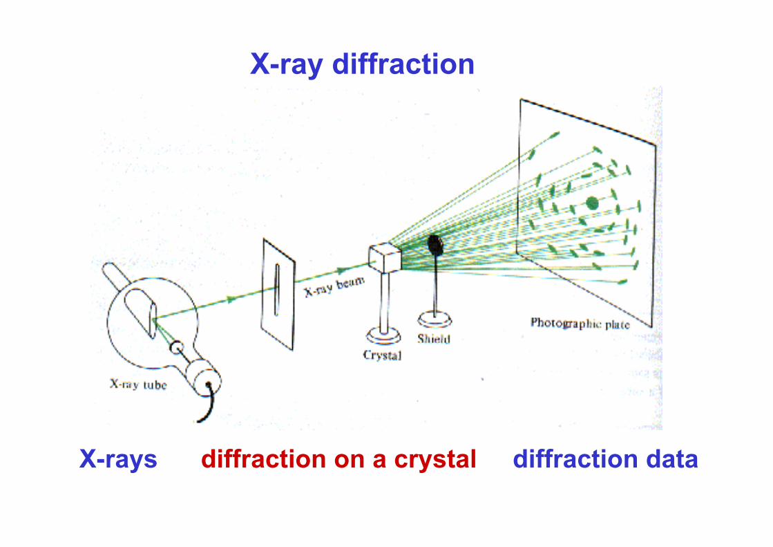
X-ray diffraction
X-rays diffraction on a crystal diffraction data

Wilhelm Conrad Röntgen’slaboratory
Würzburg, 1895.

• 22. 12. 1895.

New York 1897, See the bones of your hand for a nickel!!

Walter Friedrich, Paul Knipping & Max von Laue – first diffractogram 1912.

Electromagnetic radiation:
= 100 − 0,01 nm (1000−0,1 Å)
= 3·1015 − 3·1019 Hz
E = 12 eV − 120 keV
X-rays
Usefull wavelengths for X-ray diffraction: = 0,5 – 2,0 Å


X-ray tube
Coolidge side-window tube (scheme) K: filament (-) (thermionic effect)A: anode (+) Win and Wout: water inlet and outlet of the cooling device (C)

continuous (white)
characteristic
Continuous – deceleration of elecrons causes emission of X-rays– “Bremsstrahlung”.
At the edge X-ray photons acquire all E from the electrons hitting the anode.
Ephoton = hν = h(c/λ)
Eelectron = e × V
e – electron charge
V – voltage

anode – usually Mo orCu
fast electrons
fast elektronX-rays
(Cu K) = 1.5418 Å
(Mo K) = 0.7107 Å

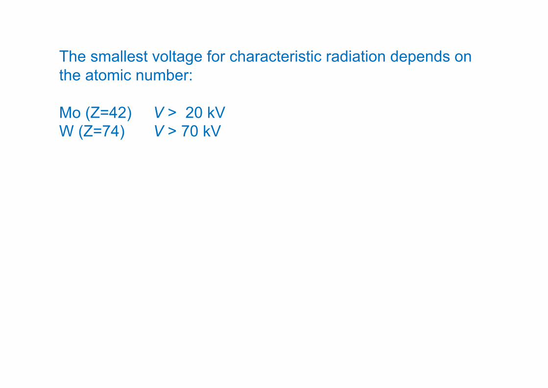
The smallest voltage for characteristic radiation depends on the atomic number:
Mo (Z=42) V > 20 kV W (Z=74) V > 70 kV

Bremsstrahlung
Deceleration of the electron near the nucleus.
Discovered by Nikola Tesla while doing research of high frequencies.
One electron can emit more photons of smaller E.

continuous characteristic
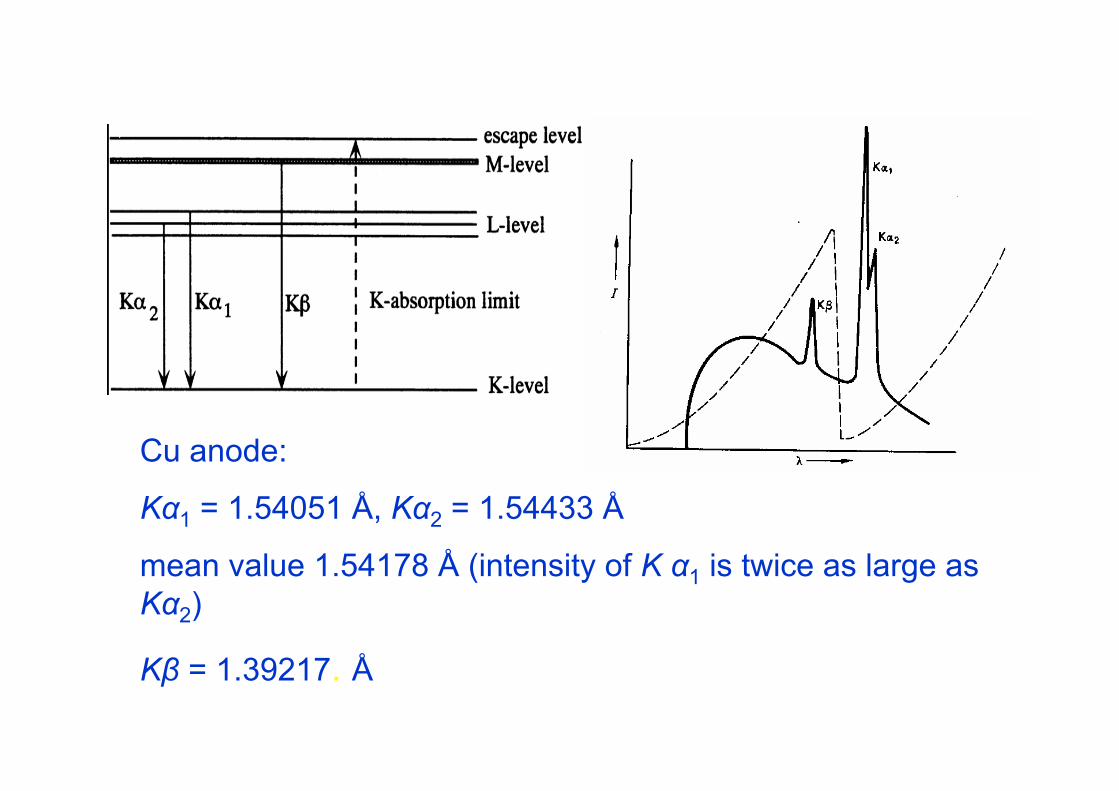
Cu anode:
Kα1 = 1.54051 Å, Kα2 = 1.54433 Å
mean value 1.54178 Å (intensity of K α1 is twice as large as Kα2)
Kβ = 1.39217. Å

Filters
Monochromatic X-rays
absorption edge of the filter
MonochromaticBragg’s law:
on a single crystal (graphite, diamond, silicon, germanium)
sin2 hkld
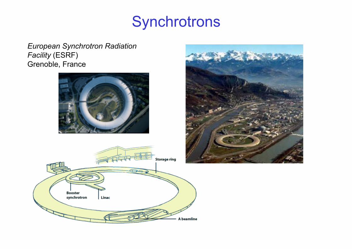
SynchrotronsEuropean Synchrotron Radiation Facility (ESRF)Grenoble, France

(FOCUSING MAGNETS)
(BENDING MAGNETS)
UNDULATOR
STORAGE RING
storage ring
BEAMLINE

ESRF


X-ray diffraction
X-rays diffraction on a crystal diffraction data
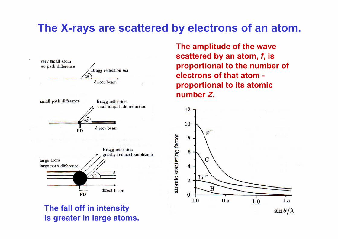
The fall off in intensityis greater in large atoms.
The X-rays are scattered by electrons of an atom.The amplitude of the wavescattered by an atom, f, isproportional to the number of electrons of that atom -proportional to its atomicnumber Z.


Diffraction on a crystal- interference of waves
In phase -constructive interference
Out of phase -destructive interference
Partially out of phase

Beam 2 has to travel the extra distance BD in comparisonto beam 1. If this path difference is equal to n (n = 1, 2, 3…)constructive interference occurs.
BC/d = sinCD/d = sin
BC = CDBD = BC+CDBD = 2BCBD = n
n = 2dsin
Bragg’s law: n = 2dsin
1
2
d

d - spacing is the perpendicular distancebetween pairs of adjacent planes
Several types of reflecting planes

Reciprocal lattice
direct reciprocal
In the reciprocal lattice the point hklis drawn at a distance1/dhkl from the origin000 in direction of thenormal between a set
of planes(hkl).

X-rays
detector


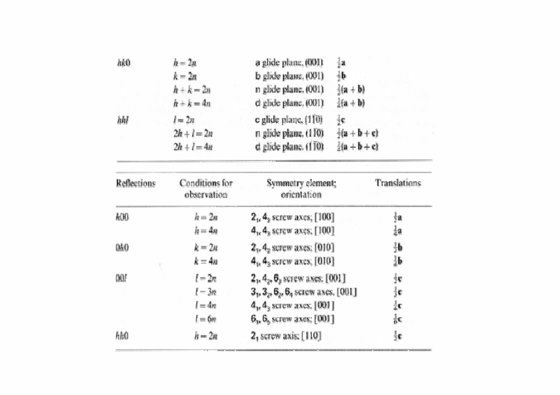
Systematically absent reflectionsSystematically absent reflections due to lattice type
Lattice type Rule for reflection hkl to be observed
P noneC h + k = 2nI h + k + l = 2nF h + k = 2n, h + l = 2n, k + l = 2nR -h + k + l = 3n
Example: reflection 100 will be present only in primitive space groups (and R); 110 in P, C, I;111 in P, C, F, R

screw axes21 || a h00 h = 2n21 || b 0k0 k = 2n21 || c, 42 || c, 63 || c 00l l = 2n31 || c, 32 || c, 62 || c 00l l = 3n41 || c, 43 || c 00l l = 4n61 || c, 65 || c 00l l = 6n
glide planes || (010)a (translac. a/2) h0l h = 2nc (translac. c/2) h0l l = 2n n (a/2+c/2) h0l h+l = 2n d (a/4+c/4) h0l h+l= 4n+1,2,3

Space group determinationfrom systematic absences
P212121reflection conditions:h00: h = 2n0k0: k = 2n00l: l = 2n
Pnmareflection conditions:0kl: k+l = 2nhk0: h = 2nh00: h = 2n0k0: k = 2n00l: l = 2n

Example: NaCl
lattice is F
reflections100, 110are absent;200, 111 are present

Crystal structure analysis
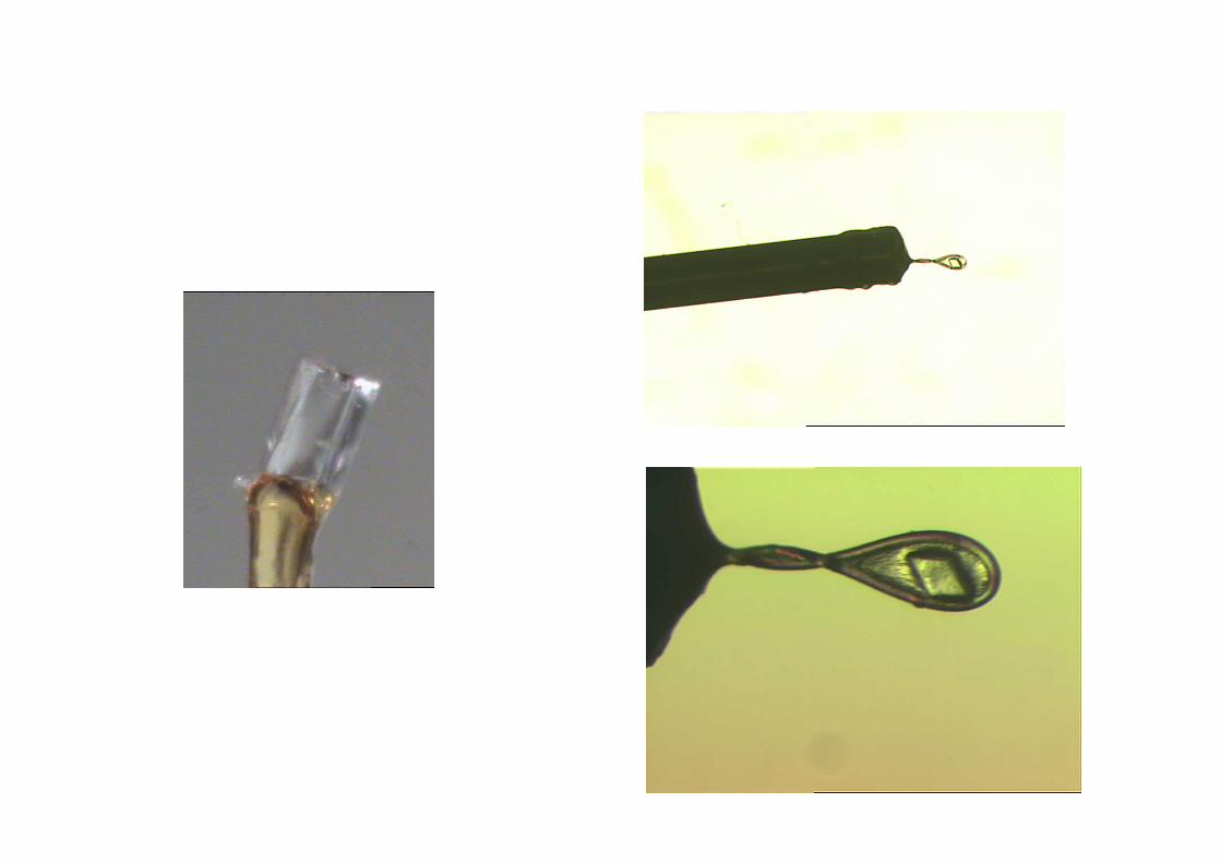
A single crystalis placed on agoniometerhead on a 4-circlediffractometer.
Detector is a photographicplate, counter, imagingplate or CCD.
A crystallographercomputes a 3-D electrondensity map byFourier synthesis
A singlecrystal experiment

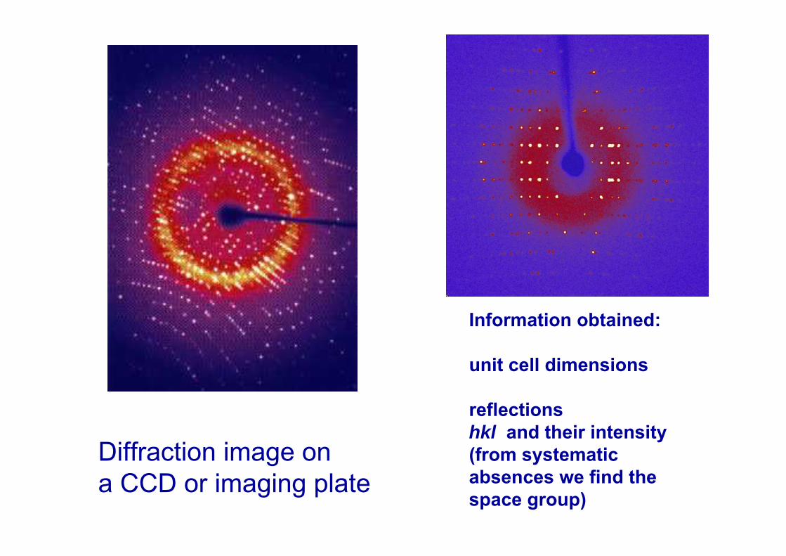
Diffraction image ona CCD or imaging plate
Information obtained:
unit cell dimensions
reflectionshkl and their intensity(from systematicabsences we find thespace group)

Pattersonand directmethods,Fouriersynthesis
From the electron density map we get fractional coordinates of atoms in the unit cell.

Structure factor
Re
Im
A
α
Complex plane (Argand (Fresnel) diagram)
]iexp[)sini(cos AA A
Wave function:
amplitude
phase

)(iexp)()( hklhklFhkl F
strukture factor
structure factor amplitude(structure amplitude)
relative phase of the structure
factor


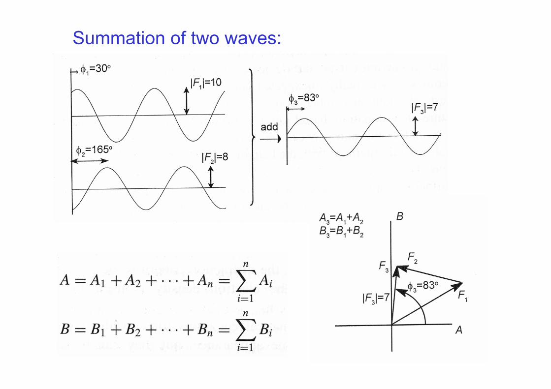
Summation of two waves:

The two components can be shown as a complex number (multiplication by i is equivalent to rotation of the vector by 90° counterclockwise).
)(iexp)()( hklhklFhkl F
V
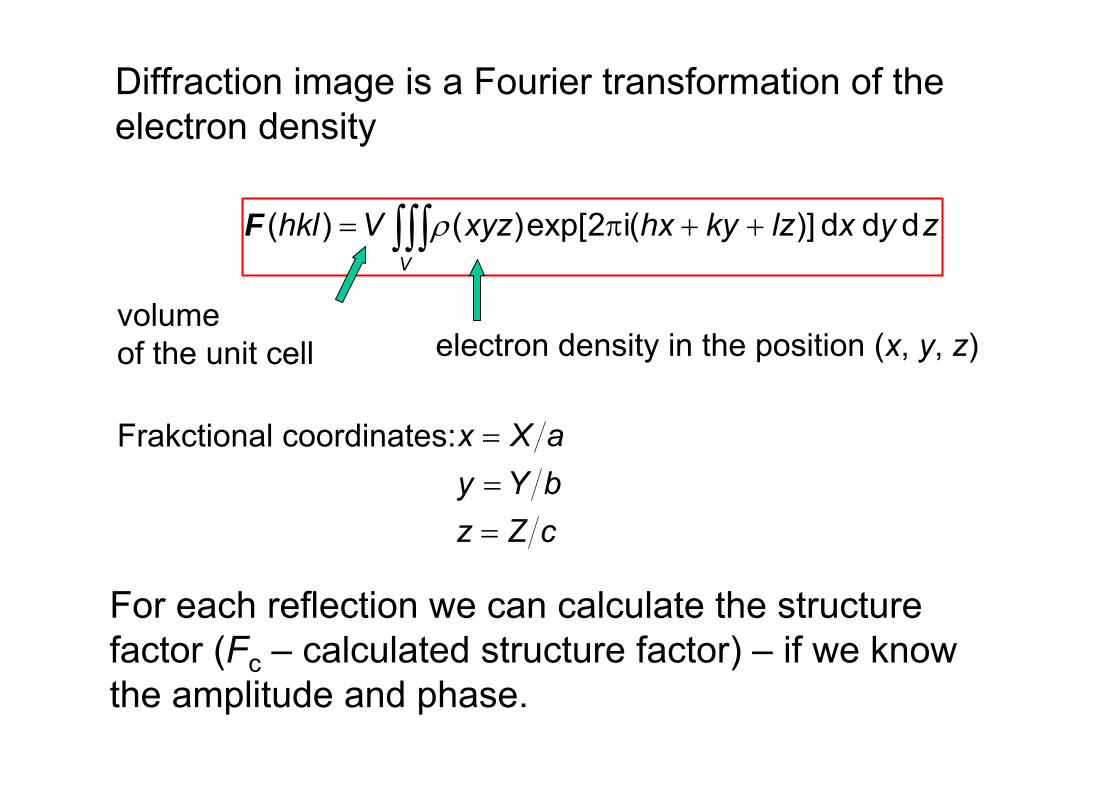
zyxlzkyhxxyzVhkl dd d )](i2exp[)()( F
electron density in the position (x, y, z)
Frakctional coordinates:
cZzbYyaXx
volume of the unit cell
Diffraction image is a Fourier transformation of theelectron density
For each reflection we can calculate the structure factor (Fc – calculated structure factor) – if we know the amplitude and phase.

The diffraction image i a Fourier transformation of one unit cell (they are all same in the crystal).
The formula shows a continuous function ρ(xyz). However addition of finite numbers is easier so the electron density is expressed by atomic scattering factors.
f3f1
f2
F(hkl)
φ(hkl)

N
jjjjj lzkyhxhklfhkl
1)](i2exp[)()(F
no. of atoms in the unit cell
atomic scattering factor of atom j
cZzbYyaXx
jj
jj
jj
Fractional coordinates of the atom:
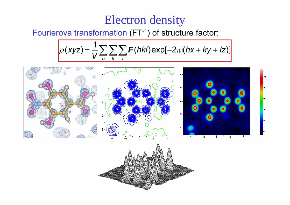
Electron density
h k l
lzkyhxhklV
xyz )](i2exp[)(1)( F
Fourierova transformation (FT-1) of structure factor:

h k l
hkllzkyhxhklFV
xyz )](i)(i2exp[)(1)(
h k l
lzkyhxhklV
xyz )](i2exp[)(1)( F
2)(hklFI PROBLEM of
PHASES
N
jjjjj lzkyhxhklfhkl
1)](i2exp[)()(F
FT-1FT
)(iexp)()( hklhklFhkl F
reciprocal space
real space

Ramachandran i Srinivasan, Nature 190 (1961) 159.
Calculated a electron density map using phases of one structure ( ) and amplitudes of another (x).
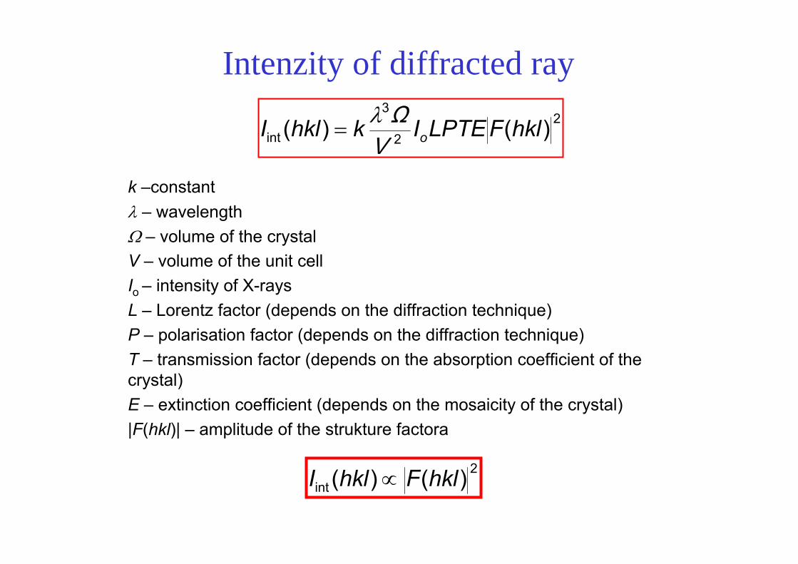
Intenzity of diffracted ray2
2
3
int )()( hklFLPTEIkhklI oVΩ
k –constant – wavelength – volume of the crystalV – volume of the unit cellIo – intensity of X-raysL – Lorentz factor (depends on the diffraction technique)P – polarisation factor (depends on the diffraction technique)T – transmission factor (depends on the absorption coefficient of the crystal)E – extinction coefficient (depends on the mosaicity of the crystal)|F(hkl)| – amplitude of the strukture factora
2int )()( hklFhklI

Data reduction• integration of diffraction maxima
22
3
int )()( hklFLPTEIkhklI oVΩ
• Lorentz, polarisation and absorption corrections
...
...
h k l I(hkl) [I(hkl)]

determination of the space groupspace group extinctions
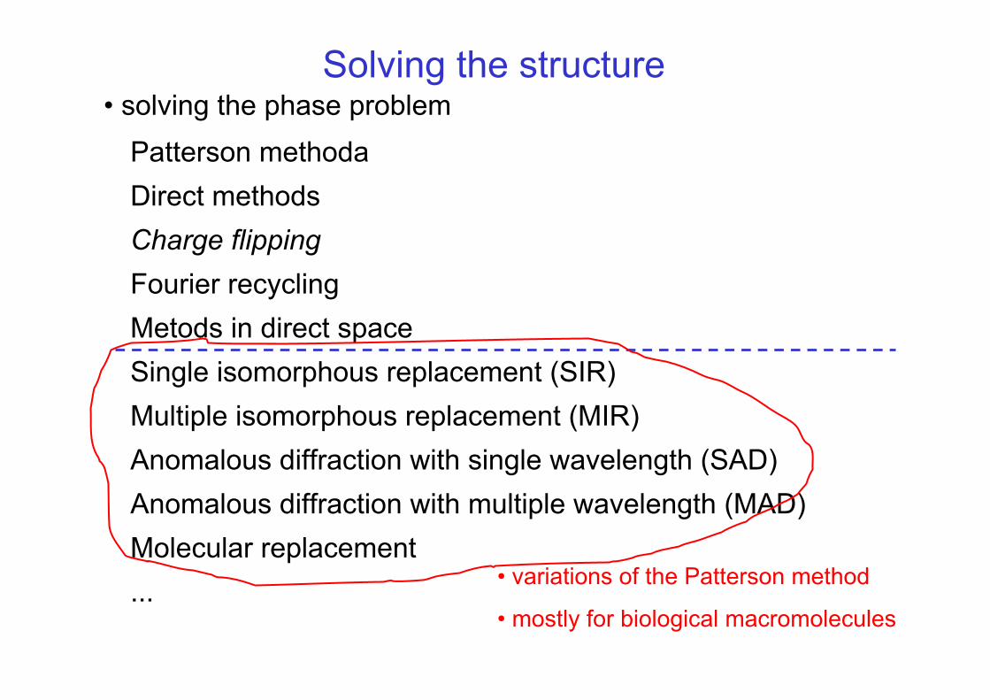
Solving the structure• solving the phase problem
Patterson methodaDirect methodsCharge flippingFourier recyclingMetods in direct spaceSingle isomorphous replacement (SIR)Multiple isomorphous replacement (MIR)Anomalous diffraction with single wavelength (SAD)Anomalous diffraction with multiple wavelength (MAD)Molecular replacement... • variations of the Patterson method
• mostly for biological macromolecules

Patterson method
h k l
lwkvhuhklFV
uvwP )(πi2exp)(1)( 2
Patterson function

Direct methodsCharacteristics of electron density define possible initial phases: diskrete atoms ρ(r) ≥ 0
Structure invariantskhkhhk
khkhhk EEENA )2( 2/1
)cosexp()(2)( 10 hkhkhkhk AAIP
k khkkhk
k khkkhkh )cos(
)sin()(tg
EEEE
Tangens formula
Shake-and-Bake – phase refinement in reciprocal space alternates with special procedures in direct space that include constraints – improves the phase

Fourier recycling (iteration)difference Fourier map of electron density
h k llz ky(hx hklhklFhklF
V
xyzxyzxyz
)2)(iexp)()(1)()()(
cco
co
0)( xyz
0)( xyz
in the position (x, y, z) in the model there is not enough electron density
in the position (x, y, z) in the model there is too much electron density
modeling of the missing parts

missing atom
Difference (Fo− Fc) map

Fo- map (calculated from observed structure amplitudes and calculated phases)
missing atom

Refinement of the structure
2co )( YYwMinimization of the function:
Y is usually |F|2w weight parametar (different fof diferent hkl)
• least-squares method
• refinement of coordinates (3 per atom), thermal displacement parameters (1 per atom for isotropic; 6 per atom for anisotropic), global scale factor of observed and calculated intensities

2/1
2o
2co )(
wYYYw
wR
o
co
FFF
R
2/12co )(
PN
YYwS
Evalution of the structure
• does it make chemical sense?
Weighted R-factor:
no. of data no. of refined parameters
S ≈ 1

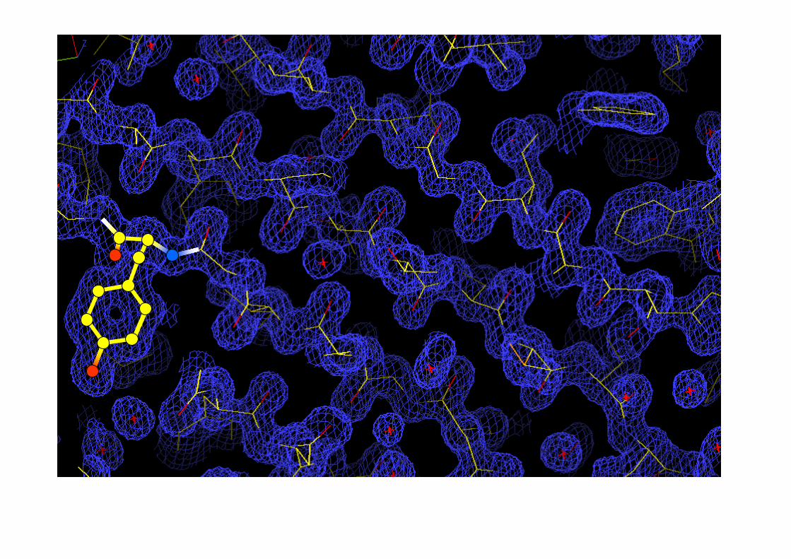
Interpretation of the structure

From the electron density map we get fractional coordinates of atoms in the unit cell.

figures courtesy of Z. Dauter
Model building at low and high resolutionModel Model buildingbuilding atat lowlow andand high high resolutionresolution