lake simcoe region conservation authority documents/reports/engineered... · report to lake simcoe...
TRANSCRIPT
REPORT
to
LAKE SIMCOE REGION CONSERVATION AUTHORITY
for
ENGINEERED WETLAND-PHOSPHEX INTEGRATION PROJECT
ADVANCED ENGINEERED WETLANDS PROCESS TO
REMOVE NUTRIENTS AND OTHER CONTAMINANTS FROM WASTEWATERS AND STORMWATERS IN THE LAKE
SIMCOE AREA
VOLUME 1 PHASE 1 TREATABILITY TESTING
PROJECT 1221 10066/7
Prepared By
Stantec Consulting 7070 Mississauga Road
Mississauga, ON L5N 7G2 Tel: (905) 817-2079 Fax: (905) 858-4426
September, 2010

The EW-Phosphex Project, Phase 1 Treatability Testing, 1221 10066/7 i © Stantec, 2010
EXECUTIVE SUMMARY
Stantec Consulting has developed and proven a highly advanced type of constructed wetland (CW) technology called engineered wetlands (EWs) which allows for much more efficient removals, winter and summer, of contaminants from wastewaters and runoffs in much smaller, more economic facilities (EW Systems) in which EW basins (cells) provide advanced secondary treatment. One type of advanced aerobic EW cell is one where the wastewater being treated flows sub-surface (SSF) beneath the surface of a bed of aggregate substrate such as gravel, and where the bed is aerated, allowing very much higher removals (often >99%) of those wastewater contaminants amenable to aerobic treatment (e.g., BOD, ammonia nitrogen). However, SSF CWs and EWs per se do not consistently remove phosphorus from wastewater, although EW Systems can incorporate phosphorus treatment as either a primary treatment step (e.g., alum precipitation in an upstream, open water basin) or a tertiary treatment step (e.g., using a downstream sand filter). However, such systems may be cumbersome for small flow situations such as those involved with de-centralized wastewater treatment. The Earth Sciences Department of the University of Waterloo (UofW) has developed and patented an advanced kind of relatively simple phosphorus removal technology using a steel slag adsorbent known as Phosphex™ which can remove phosphorus from wastewaters to very low levels, and which has the potential to supplement other kinds of treatment as a treatment step in an EW System. The Lake Simcoe Region Conservation Authority (LSRCA) believes that EW Systems incorporating the Phosphex™ technology would have wide applicability in the watersheds around Lake Simcoe, allowing significant reductions in the concentrations of contaminants, especially phosphorus, in the effluents from new and upgraded existing wastewater and stormwater management facilities. The Centre for Alternative Wastewater Treatment (CAWT) at the Frost Campus in Lindsay, ON of Fleming College (the College) has existing bench, pilot- and demonstration-scale wetland treatment facilities, and works with Stantec to develop new applications for wetland treatment. In order to integrate the EW and Phosphex™ technologies, a multi-phase project, the Engineered Wetland-Phosphex Integration Project (the EW-Phosphex Project or the Project) was initiated. The first phase of the Project was Phase 1A, indoor proof-of-concept pilot testing and the second, Phase 1B, outdoor, demonstration-scale testing at about 100 times the influent flow rate of the Phase 1A unit [~ 4 - 5 m3/d vs the 50 – 100 L/d of the pilot unit]). Both units are located at CAWT‟s facilities at Fleming College and use sewage from the College as a feedstock. This report presents the results of the Phase 1 using the Pilot Unit and the Demonstration Unit, the purpose of both of which was to demonstrate the feasibility of incorporating a Phosphex cell into an EW System; to assess the ability of such an EW System to address and overcome the perceived problems of the Phosphex™ technology (high pH effluent, metal leaching, bed plugging); and to define morphology and operating conditions of larger scale facilities. The results of Phase 1A indicate that the concept of incorporating a Phosphex cell into an EW System as a tertiary treatment step is indeed feasible and such a system involving an aerated SSF EW cell upstream of it can clean up sanitary sewage with a high degree of efficiency, can reduce influent phosphorus levels to over 99.9% and at

The EW-Phosphex Project, Phase 1 Treatability Testing, 1221 10066/7 ii © Stantec, 2010
the same time disinfecting effluent. To do so some sort of pH reduction step proved to be is needed after the Phosphex treatment step. During the Phase 1A testing, carbon dioxide gas was used to do so. While other kinds of acids (e.g., ferric chloride) might also be considered, carbon dioxide gas is probably the best choice as it is easy to handle; widely available at relatively low prices; CO2 injection equipment is readily available, off-the-shelf; and this option will be more compatible with the treatment of smaller sewage flows such as those from de-centralized situations. In addition to removing phosphorus, the Pilot Unit‟s Phosphex Cell also removed those remaining amounts of cBOD that were not removed in the upstream Aerated Cell, indicating that Phosphex cells can be expected to act in polishing roles for labile residual organics allowing EW-Phosphex systems to achieve very low effluent cBOD levels. Better than 99% removals of phosphorus can be achieved in an EW-Phosphex system. Except for vanadium, metal leaching from the Phosphex Cell‟s steel slag substrate was not a problem.
Both Aerated EW cells and Phosphex cells disinfect a wastewater passing through them, eliminating the need for separate downstream disinfection unit processes. The Phase 1B Demonstration Unit also was quite successful and achieved its objectives. Most of the findings of the Phase 1A Pilot Unit Testing were confirmed in the Phase 1B Demonstration Unit.
Adding zero valent iron near the outlet distributor of the Phosphex Cell resolved problems associated with the leaching of vanadium from the cell‟s steel slag substrate.
A morphology for Phase 2 field testing was defined. This would involve some sort of inlet feedwater holding tank, an aerated VSSF EW cell, a sacrificial slag vessel, a Phosphex cell and some sort of downstream holding tank or basin into which carbon dioxide can be injected automatically to control effluent pH. A further downstream aerobic polishing cell might also have to be included to deal with ammonia and nitrites in Phosphex cell effluent.
There was turbidity in the wastewater entering the Phosphex Cell of the Demonstration Unit but it was not determined if this was due to tufa, apatite, or degraded organics. The possibility of wastewater contamination with a foreign organic substance could not be eliminated, although neither could the more likely explanation, ammonia bounceback due to partial reduction of nitrate in the Phosphex Cell.
A “sacrificial” slag cell in front of a Phosphex Cell seemed to be successful in limiting or preventing any tufa build up in it but operations could not be carried out long enough to confirm this.
The following are some general recommendations from the Phase 1 EW-Phosphex Project Treatability Test.
1) The Phase 1B EW-Phosphex Demonstration Unit should continue to be
operated through the winter of 2010-2011 if funding to do so can be secured.
The EW-Phosphex Project, Phase 1 Treatability Testing, 1221 10066/7 iii © Stantec, 2010
This will be needed to resolve the Phosphex cell nitrogen issue and to demonstrate operations in cold weather.
2) Steel slag as delivered from a steel mill always contains some fine lime between its particles (2 – 8%) and as much of this material as possible needs to be removed before the slag is used as the substrates in Phosphex cells. Outdoor storage for at least six months before use would be desirable. Slags used should be screened and washed before use and particle sizes of ¾” and greater are recommended. Fine slag material (richer in lime) should never be used as substrate in a Phosphex unit.
3) Zero valent iron should be added near the outlet of Phosphex cells constructed
in future.
Phase 1 of the EW-Phosphex Project showed that all of the three major drawbacks that some had earlier identified as being of concern with the use of the Phosphex™ technology (plugging, substrate metal leaching, and high pH effluents) can be mitigated by incorporating the technology into an EW System. The EW-Phosphex Project is now ready to proceed with a Phase 2, full-scale demonstration of the EW-Phosphex technology at a community in the Lake Simcoe watershed.

The EW-Phosphex Project, Phase 1 Treatability Testing, 1221 10066/7 i © Stantec, 2010
TABLE OF CONTENTS Volume 1
1. INTRODUCTION ................................................................................................. 1
1.1 Background .................................................................................................. 1 1.2 Engineered Wetlands ................................................................................... 1 1.3 The Phosphex™ Technology ....................................................................... 3 1.4 The EW-Phosphex Project ........................................................................... 4 1.5 Phase 1A Pilot Testing ................................................................................. 5 1.6 Phase 1B Demonstration Testing ................................................................. 5 1.7 Phase 2 Field Testing .................................................................................. 6 1.8 This Report .................................................................................................. 6
2. SCOPE OF PHASE 1 .......................................................................................... 7
2.1 The Phase 1A Pilot Unit ............................................................................... 7 2.2 The Phase 1B Demonstration Unit ............................................................... 7 2.3 Objectives of Phase 1A Pilot Testing ........................................................... 7 2.4 Objectives of Phase 1B Demonstration Testing ........................................... 8 2.5 Feedstock for Phase 1 ................................................................................. 8 2.6 Substrate for Phase 1 .................................................................................. 8
3. DESIGN AND CONSTRUCTION OF THE PHASE 1A PILOT UNIT.................... 9
3.1 Phase 1A Pilot Unit Layout........................................................................... 9 3.2 Phase 1A Pilot Unit Mixing Tank ................................................................ 15 3.3 Phase 1A Pilot Unit Aerated Cell ................................................................ 15 3.4 Phase 1A Pilot Unit Phosphex Cell ............................................................ 16 3.5 Phase 1A Pilot Unit Open Tank Cell ........................................................... 17 3.6 Phase 1A Pilot Unit Polishing Cell .............................................................. 17
4. DESIGN AND MODIFICATION OF THE PHASE 1B DEMONSTRATION UNIT19
4.1 The Fleming Wetland Test Facility ............................................................. 19 4.2 The Phase 1B Demonstration Unit ............................................................. 20 4.3 The Phase 1B HSSF CW Cell .................................................................... 21 4.4 The Phase 1B Aerated VSSF EW Cell ....................................................... 21 4.5 The Phase 1B Demonstration Unit‟s Sacrificial Slag Drum ......................... 26 4.6 The Phase 1B Demonstration Unit‟s Phosphex Cell ................................... 27 4.7 Phase 1B CO2 Bubbler Tanks ................................................................... 34
5. OPERATION OF THE PHASE 1A PILOT UNIT ................................................ 36
5.1 Phase 1A Pilot Unit Process Flow .............................................................. 36 5.2 Schedule for Phase 1A Pilot Unit Operations ............................................. 36 5.3 Phase 1A Pilot Unit Operations .................................................................. 37
The EW-Phosphex Project, Phase 1 Treatability Testing, 1221 10066/7 ii © Stantec, 2010
6. OPERATION OF THE PHASE 1B DEMONSTRATION UNIT ........................... 42
6.1 Phase 1B Demonstration Unit Process Flow .............................................. 42 6.2 Schedule for Phase 1B Demonstration Unit Operations ............................. 43 6.3 Phase 1B Demonstration Unit Operations .................................................. 44
7. ANALYTICAL TESTING & METHODOLOGY ................................................... 47
7.1 Phase 1 Monitoring .................................................................................... 47 7.2 Sampling Carried Out ................................................................................. 48 7.3 Analytical Test Procedures Carried Out by CAWT ..................................... 49 7.4 Analytical Test Procedures Carried Out by UofW ....................................... 52
8. DISCUSSION OF RESULTS FOR PHASE 1A PILOT TESTING ...................... 54
8.1 General ...................................................................................................... 54 8.2 Total Phosphorus Removal during Phase 1A ............................................. 54 8.3 Ortho-Phosphate Removal during Phase 1A Pilot Unit Testing .................. 55 8.4 pH and Alkalinity during Phase 1A ............................................................. 56 8.5 Dissolved Oxygen during Phase 1A Pilot Unit Testing ............................... 58 8.6 Conductivity during Phase 1A Pilot Unit Testing ......................................... 58 8.7 cBOD and COD during Phase 1A Pilot Unit Testing ................................... 59 8.8 Ammonia Nitrogen & Nitrate Nitrogen during Phase 1A Pilot Unit Testing .. 59 8.9 Pathogen Indicators during Phase 1A Pilot Unit Testing ............................ 60 8.10 Metals during Phase 1A Pilot Unit Testing ................................................. 61 8.11 Temperature during Phase 1A Pilot Unit Testing ........................................ 62 8.12 Opening of the Phase 1A Pilot Unit Phosphex Cell .................................... 63 8.13 Summary of Results for Phase 1A Pilot Unit Testing .................................. 66
9. DISCUSSION OF RESULTS FOR DEMONSTRATION UNIT TESTING ........... 67
9.1 General ...................................................................................................... 67 9.2 Total Phosphorus Removal during Phase 1B ............................................. 67 9.3 Ortho-Phosphate Removal during Phase 1B Demonstration Unit Testing .. 67 9.4 pH and Alkalinity during Phase 1B ............................................................. 68 9.5 Dissolved Oxygen during Phase 1B Demonstration Unit Testing ............... 68 9.6 Conductivity during Phase 1B Demonstration Unit Testing ........................ 69 9.7 cBOD and COD during Phase 1B Demonstration Unit Testing ................... 69 9.8 Ammonia Nitrogen & Nitrate Nitrogen during Demonstration Unit Testing .. 69 9.9 Pathogen Indicators during Phase 1B Demonstration Unit Testing ............ 71 9.10 Metals Removals during Phase 1B Demonstration Unit Testing ................. 71 9.11 Temperatures during Phase 1B Demonstration Unit Testing ...................... 72 9.12 Summary of Results for Phase 1B Demonstration Unit Testing .................. 72
10. CONCLUSIONS AND RECOMMENDATIONS .................................................. 74
11. CLOSURE ......................................................................................................... 77

The EW-Phosphex Project, Phase 1 Treatability Testing, 1221 10066/7 iii © Stantec, 2010
LIST OF TABLES Table 5.1: Pilot Unit Wastewater Flows ......................................................................... 39 Table 5.2: Events during Phase 1A Pilot Testing ........................................................... 40 Table 6.1: Phase 1B Demonstration Unit Construction Events ...................................... 43 Table 6.2: Phase 1B Demonstration Unit Wastewater Flows ......................................... 45 Table 7.1: Sampling Frequency for the Pilot Unit ........................................................... 50 Table 7.2: Sampling Frequency for the Demonstration Unit ........................................... 50 Table 8.1: Pilot Unit Nitrogen Balance (mg/L) ................................................................ 60 Table 9.1: Demonstration Unit Nitrogen Balance (mg/L) ................................................ 70 LIST OF FIGURES Figure 3.1: Design of Phase 1A Pilot EW Cell Inlet Distribution Matrix .......................... 11 Figure 3.2: Design of Phase 1A Pilot EW Cell Outlet Distribution Matrix........................ 12 Figure 4.1: Test Cell Sizes for the Fleming Wetland Test Facility .................................. 19 Figure 4.2: The Fleming Wetland Test Facility............................................................... 19 Figure 4.3: Aerated Cell Aeration System Design………………………………….. 22 Figure 4.4: Sketch of Demonstration Unit Aerated Cell ................................................ 26 Figure 4.5: Sketch of Demonstration Unit Phosphex Cell .............................................. 33 Figure 5.1: Process Flow for the Phase 1A Pilot Unit .................................................... 36 Figure 6.1: Process Flow for the Phase 1B Demonstration Unit .................................... 42 Figure 8.1: Total Phosphorus Concentrations during Phase 1A .................................... 55 Figure 8.2: Ortho-Phosphate Concentrations during Phase 1A Pilot Testing ................. 56 Figure 8.3: pHs during Phase 1A Pilot Testing .............................................................. 57 Figure 8.4: Alkalinity during Phase 1A Pilot Unit Testing ............................................... 58 Figure 8.5: Locations where Substrate Samples Were Taken from the Phosphex Cell .. 64 LIST OF PICTURES Picture 3.1: A View of the EW-Phosphex Pilot Unit ......................................................... 9 Picture 3.2: Delivery Matrix as Constructed Between Pilot Unit Cells ............................ 10 Picture 3.3: Outlet Distribution Matrix in Phase 1A EW Cell Bottom .............................. 10 Picture 3.4: Removing the Top From a Chemical Tote .................................................. 13 Picture 3.5: A Tote with Its Top Removed to Allow Its Use as a Test Cell ...................... 13 Picture 3.6: Piping Connections between Phase 1A Pilot EW Cells ............................... 14 Picture 3.7: All Phase 1A Pilot EW Cells in Place at Fleming College ........................... 15 Picture 3.8: Vegetated Phase 1A Aerated EW Cell with Inlet Distribution Matrix ........... 16 Picture 3.9: Preparation of the Phase 1A Pilot Phosphex Cell ....................................... 17
The EW-Phosphex Project, Phase 1 Treatability Testing, 1221 10066/7 iv © Stantec, 2010
Picture 3.10: Side View of Assembled Phase 1A EW-Phosphex Pilot Unit .................... 18 Picture 4.1: Pump Chamber at Fleming Wetland Test Facility ....................................... 20 Picture 4.2: Empty Phase 1B Demonstration Unit Aerated Cell ..................................... 21 Picture 4.3: Aeration Tubing Being Placed in the Bottom of the Aerated Cell ................ 22 Picture 4.4: Gravel Substrate Being Added to Demonstration Unit Aerated Cell ............ 23 Picture 4.5: Gravel Substrate Being Added to the Demonstration Unit Aerated Cell ...... 23 Picture 4.6: Inlet Distribution Matrix on Top of Phase 1B Aerated Cell .......................... 24 Picture 4.7: Aerated Cell Inlet Distributor Operation ...................................................... 24 Picture 4.8: Inlet Distributors Were Heat-Traced ........................................................... 25 Picture 4.9: Demonstration Unit Air Blowers .................................................................. 25 Picture 4.10: Sacrifical Slag Drum ................................................................................. 27 Picture 4.11: Phase 1B Phosphex Cell Outlet Collection Piping on Cell Floor ............... 27 Picture 4.12: Demonstration Unit Phosphex Cell Outlet Piping ...................................... 28 Picture 4.13: Iron Filings for Bottom of Phosphex Cell ................................................... 28 Picture 4.14: Iron Filings Being Placed at Bottom of Phosphex Cell .............................. 29 Picture 4.15: Iron Filings among Gravel Particles .......................................................... 29 Picture 4.16: Demonstration Unit Phosphex Cell Inlet Distribution Grid ......................... 30 Picture 4.17: Connection of Phosphex Cell Inlet Distribution Grid.................................. 30 Picture 4.18: Covering Phosphex Cell Inlet Distribution Grid with Gravel ....................... 31 Picture 4.19: Tarp over Demonstration Unit Phosphex Cell ........................................... 31 Picture 4.20: Sand Placed over Phosphex Cell Tarp ..................................................... 32 Picture 4.21: Completed Demonstration Unit Phosphex Cell ......................................... 32 Picture 4.22: The Phase 1B Demonstration Unit ........................................................... 33 Picture 4.23: CO2 Bubbler Tanks ................................................................................... 34 Picture 4.24: CO2 Addition Timer ................................................................................... 34 Picture 4.25: CO2 Flow Meter ........................................................................................ 35 Picture 5.1: Phase 1A Pilot Unit Aerated Cell in Operation ............................................ 38 Picture 5.2: Pilot Unit Polishing Cell Early During Phase 1A .......................................... 38 Picture 5.3: The Phase 1A EW-Phosphex Pilot Unit during Early Operations ................ 39 Picture 8.1: The Phosphex Cell‟s Inlet Distributor at the End of Phase 1A ..................... 63 Picture 8.2: Cemented Substrate in the Opened Phase 1A Phosphex Cell ................... 64 Picture 8.3: Samples Collected from the Phase 1A Pilot Unit Phosphex Cell for Detailed Mineralogical Study ....................................................................................................... 65

The EW-Phosphex Project, Phase 1 Treatability Testing, 1221 10066/7 v © Stantec, 2010
TABLE OF CONTENTS FOR VOLUME 2, APPENDICES THESE APPENDICES ARE BOUND SEPARATELY
APPENDIX A EXPERIMENTAL DATA FROM PHASE 1A PILOT OPERATIONS APPENDIX B EXPERIMENTAL DATA FROM PHASE 1B DEMONSTRATION UNIT OPERATIONS APPENDIX C CONSTRUCTED WETLANDS C.1 Wetlands C.2 Natural Wetlands C.3 Treatment Wetlands C.4 Constructed Wetlands C.5 Stormwater Wetlands C.6 Constructed Treatment Wetlands C.7 Types of Constructed Wetlands C.8 Free Water Surface Wetlands C.9 Sub-Surfaced Flow Wetlands C.10 Horizontal Sub-Surface Flow Wetlands C.11 Vertical Sub-Surface Flow (VSSF) Wetlands C.12 CW Vegetation C.13 Pollutant Removal in CWs C.14 Aerobic Wetlands C.15 Anaerobic Wetlands C.16 Advantage and Disadvantages of Constructed Wetlands APPENDIX D ENGINEERED WETLANDS D.1 Engineered Wetlands D.2 EW Systems D.3 Engineered Stormwater Wetlands (ESWs) D.4 Aerated SSF Wetlands D.5 Fill & Drain Wetlands D.6 Anaerobic SSF Wetlands D.7 Anaerobic Biochemical Reactors D.8 Wastewaters Treatable in EW Systems D.9 Design of EW Systems D.10 Treatability Testing D.11 The Effect of Temperature on EW Systems D.12 Sludge Formation in EW Systems

The EW-Phosphex Project, Phase 1 Treatability Testing, 1221 10066/7 vi © Stantec, 2010
APPENDIX E PHOSPHORUS REMOVAL E.1 Lake Simcoe Protection Plan E.2 Phosphorus Basics E.3 Phosphorus Removal Processes E.3.1 Process of Phosphorus Removal from Wastewaters E.3.2 Phosphorus Removal by Settling E.3.3 Phosphorus Removal by Precipitation E.3.3.1 Phosphorus Removal by Metal Salts E.3.3.2 Phosphorus Removal Using Alum E.3.3.3 Phosphorus Removal Using Ferric Chloride E.3.3.4 Phosphorus Removal Using Lime E.3.3.5 Phosphorus Removal Using Ferrous and Ferric Sulphates E.3.4 Biological Nutrient Removal E.3.5 Combination Processes E.3.6 Sorption Processes E.4 Steel Slags E.5 The PhosphexTM Processes E.5.1 The PhosphexTM Patent E.5.2 Development of the PhosphexTM Technology E.5.3 Other PhosphexTM Demonstration Projects E.6 Phosphorus Removal in Wetlands APPENDIX F REFERENCES
Proprietary Restriction Notice THIS DOCUMENT CONTAINS INFORMATION PROPRIETARY TO STANTEC AND SHALL NOT BE REPRODUCED OR TRANSFERRED TO OTHER DOCUMENTS, OR DISCLOSED TO OTHERS, OR USED FOR ANY PURPOSE OTHER THAN THAT FOR WHICH IT IS FURNISHED WITHOUT THE PRIOR WRITTEN PERMISSION OF STANTEC. NO PORTION OF IT SHALL BE USED IN THE FORMULATION OF A REQUEST FOR PROPOSAL FOR OPEN BID, NOW OR IN THE FUTURE, BY THE AGENCIES AND/OR PERSONS WHO MAY SEE IT IN THE PROCESS OF ITS REVIEW, WITHOUT THE PRIOR WRITTEN PERMISSION OF STANTEC.
EW-Phosphex Project, Phase 1 Treatability Testing, 1221 10066/7 © Stantec, 2010
1
THE EW-PHOSPHEX PROJECT, PHASE 1 TREATABILITY TESTING
1. INTRODUCTION
1.1 Background
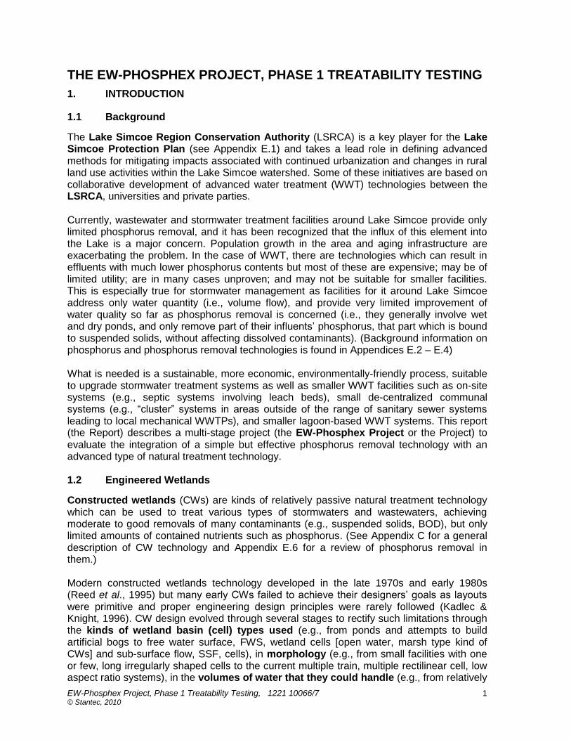
The Lake Simcoe Region Conservation Authority (LSRCA) is a key player for the Lake Simcoe Protection Plan (see Appendix E.1) and takes a lead role in defining advanced methods for mitigating impacts associated with continued urbanization and changes in rural land use activities within the Lake Simcoe watershed. Some of these initiatives are based on collaborative development of advanced water treatment (WWT) technologies between the LSRCA, universities and private parties. Currently, wastewater and stormwater treatment facilities around Lake Simcoe provide only limited phosphorus removal, and it has been recognized that the influx of this element into the Lake is a major concern. Population growth in the area and aging infrastructure are exacerbating the problem. In the case of WWT, there are technologies which can result in effluents with much lower phosphorus contents but most of these are expensive; may be of limited utility; are in many cases unproven; and may not be suitable for smaller facilities. This is especially true for stormwater management as facilities for it around Lake Simcoe address only water quantity (i.e., volume flow), and provide very limited improvement of water quality so far as phosphorus removal is concerned (i.e., they generally involve wet and dry ponds, and only remove part of their influents‟ phosphorus, that part which is bound to suspended solids, without affecting dissolved contaminants). (Background information on phosphorus and phosphorus removal technologies is found in Appendices E.2 – E.4) What is needed is a sustainable, more economic, environmentally-friendly process, suitable to upgrade stormwater treatment systems as well as smaller WWT facilities such as on-site systems (e.g., septic systems involving leach beds), small de-centralized communal systems (e.g., “cluster” systems in areas outside of the range of sanitary sewer systems leading to local mechanical WWTPs), and smaller lagoon-based WWT systems. This report (the Report) describes a multi-stage project (the EW-Phosphex Project or the Project) to evaluate the integration of a simple but effective phosphorus removal technology with an advanced type of natural treatment technology. 1.2 Engineered Wetlands
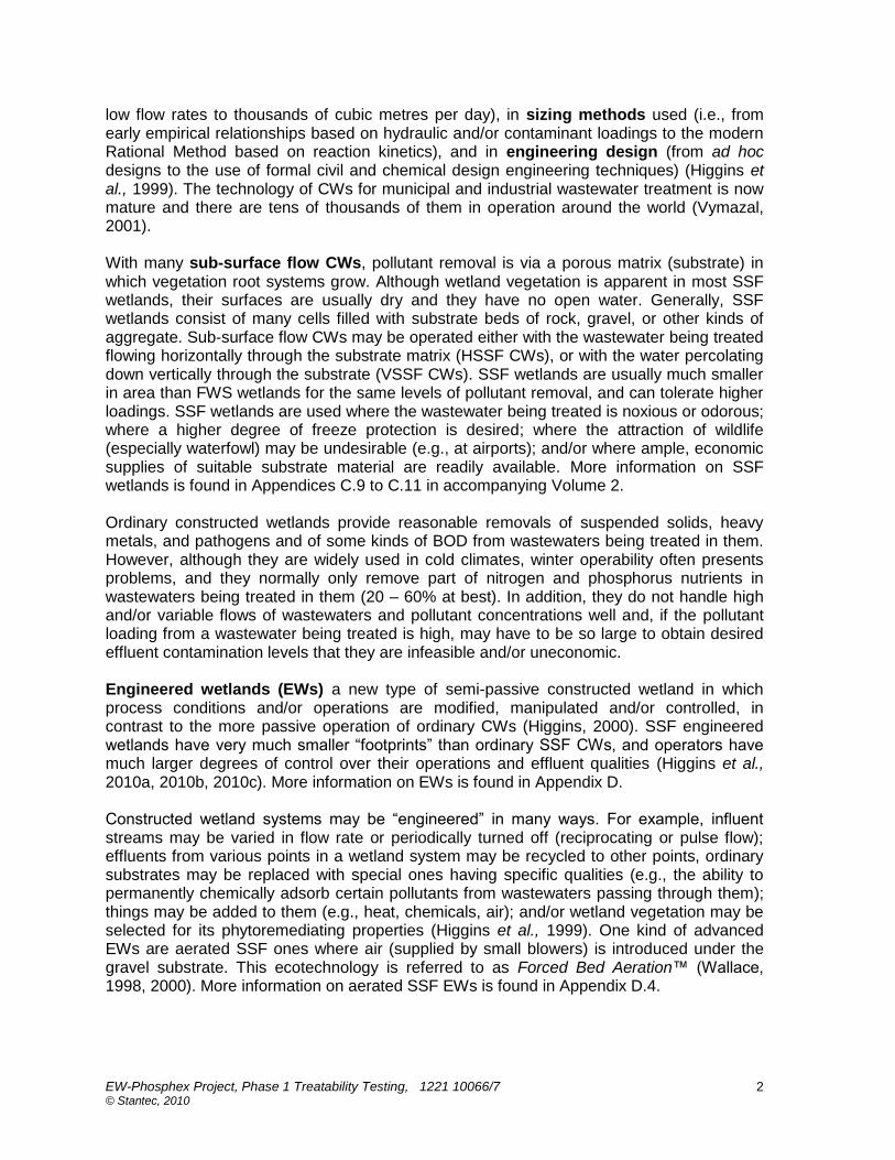
Constructed wetlands (CWs) are kinds of relatively passive natural treatment technology which can be used to treat various types of stormwaters and wastewaters, achieving moderate to good removals of many contaminants (e.g., suspended solids, BOD), but only limited amounts of contained nutrients such as phosphorus. (See Appendix C for a general description of CW technology and Appendix E.6 for a review of phosphorus removal in them.) Modern constructed wetlands technology developed in the late 1970s and early 1980s (Reed et al., 1995) but many early CWs failed to achieve their designers‟ goals as layouts were primitive and proper engineering design principles were rarely followed (Kadlec & Knight, 1996). CW design evolved through several stages to rectify such limitations through the kinds of wetland basin (cell) types used (e.g., from ponds and attempts to build artificial bogs to free water surface, FWS, wetland cells [open water, marsh type kind of CWs] and sub-surface flow, SSF, cells), in morphology (e.g., from small facilities with one or few, long irregularly shaped cells to the current multiple train, multiple rectilinear cell, low aspect ratio systems), in the volumes of water that they could handle (e.g., from relatively
EW-Phosphex Project, Phase 1 Treatability Testing, 1221 10066/7 © Stantec, 2010
2
low flow rates to thousands of cubic metres per day), in sizing methods used (i.e., from early empirical relationships based on hydraulic and/or contaminant loadings to the modern Rational Method based on reaction kinetics), and in engineering design (from ad hoc designs to the use of formal civil and chemical design engineering techniques) (Higgins et al., 1999). The technology of CWs for municipal and industrial wastewater treatment is now mature and there are tens of thousands of them in operation around the world (Vymazal, 2001). With many sub-surface flow CWs, pollutant removal is via a porous matrix (substrate) in which vegetation root systems grow. Although wetland vegetation is apparent in most SSF wetlands, their surfaces are usually dry and they have no open water. Generally, SSF wetlands consist of many cells filled with substrate beds of rock, gravel, or other kinds of aggregate. Sub-surface flow CWs may be operated either with the wastewater being treated flowing horizontally through the substrate matrix (HSSF CWs), or with the water percolating down vertically through the substrate (VSSF CWs). SSF wetlands are usually much smaller in area than FWS wetlands for the same levels of pollutant removal, and can tolerate higher loadings. SSF wetlands are used where the wastewater being treated is noxious or odorous; where a higher degree of freeze protection is desired; where the attraction of wildlife (especially waterfowl) may be undesirable (e.g., at airports); and/or where ample, economic supplies of suitable substrate material are readily available. More information on SSF wetlands is found in Appendices C.9 to C.11 in accompanying Volume 2. Ordinary constructed wetlands provide reasonable removals of suspended solids, heavy metals, and pathogens and of some kinds of BOD from wastewaters being treated in them. However, although they are widely used in cold climates, winter operability often presents problems, and they normally only remove part of nitrogen and phosphorus nutrients in wastewaters being treated in them (20 – 60% at best). In addition, they do not handle high and/or variable flows of wastewaters and pollutant concentrations well and, if the pollutant loading from a wastewater being treated is high, may have to be so large to obtain desired effluent contamination levels that they are infeasible and/or uneconomic. Engineered wetlands (EWs) a new type of semi-passive constructed wetland in which process conditions and/or operations are modified, manipulated and/or controlled, in contrast to the more passive operation of ordinary CWs (Higgins, 2000). SSF engineered wetlands have very much smaller “footprints” than ordinary SSF CWs, and operators have much larger degrees of control over their operations and effluent qualities (Higgins et al., 2010a, 2010b, 2010c). More information on EWs is found in Appendix D. Constructed wetland systems may be “engineered” in many ways. For example, influent streams may be varied in flow rate or periodically turned off (reciprocating or pulse flow); effluents from various points in a wetland system may be recycled to other points, ordinary substrates may be replaced with special ones having specific qualities (e.g., the ability to permanently chemically adsorb certain pollutants from wastewaters passing through them); things may be added to them (e.g., heat, chemicals, air); and/or wetland vegetation may be selected for its phytoremediating properties (Higgins et al., 1999). One kind of advanced EWs are aerated SSF ones where air (supplied by small blowers) is introduced under the gravel substrate. This ecotechnology is referred to as Forced Bed Aeration™ (Wallace, 1998, 2000). More information on aerated SSF EWs is found in Appendix D.4.
EW-Phosphex Project, Phase 1 Treatability Testing, 1221 10066/7 © Stantec, 2010
3
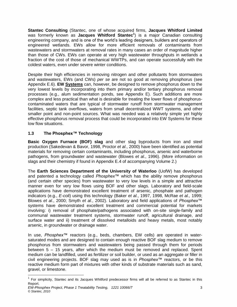
Stantec Consulting (Stantec, one of whose acquired firms, Jacques Whitford Limited was formerly known as Jacques Whitford Stantec1) is a major Canadian consulting engineering company, and is one of the world‟s leading designers, builders and operators of engineered wetlands. EWs allow for more efficient removals of contaminants from wastewaters and stormwaters at removal rates in many cases an order of magnitude higher than those of CWs. EWs can operate at very high wastewater throughputs in wetlands a fraction of the cost of those of mechanical WWTPs, and can operate successfully with the coldest waters, even under severe winter conditions. Despite their high efficiencies in removing nitrogen and other pollutants from stormwaters and wastewaters, EWs (and CWs) per se are not so good at removing phosphorus (see Appendix E.6). EW Systems can, however, be designed to remove phosphorus down to the very lowest levels by incorporating into them primary and/or tertiary phosphorus removal processes (e.g., alum sedimentation ponds, see Appendix E). Such additions are more complex and less practical than what is desirable for treating the lower flows of phosphorus-contaminated waters that are typical of stormwater runoff from stormwater management facilities, septic tank overflows, waters from small decentralized WWT systems, and other smaller point and non-point sources. What was needed was a relatively simple yet highly effective phosphorus removal process that could be incorporated into EW Systems for these low flow situations. 1.3 The Phosphex™ Technology
Basic Oxygen Furnace (BOF) slag and other slag byproducts from iron and steel production (Sakedevan & Bavor, 1998, Proctor et al., 2000) have been identified as potential materials for removing certain contaminants, including phosphorus, arsenic and waterborne pathogens, from groundwater and wastewater (Blowes et al., 1996). (More information on slags and their chemistry if found in Appendix E.4 of accompanying Volume 2.) The Earth Sciences Department of the University of Waterloo (UofW) has developed and patented a technology called Phosphex™ which has the ability remove phosphorus (and certain other species) from wastewater to very low levels in a simple and attractive manner even for very low flows using BOF and other slags. Laboratory and field-scale applications have demonstrated excellent treatment of arsenic, phosphate and pathogen indicators (e.g., E-coli) using this technology (Baker et al., 1997, 1998, McRae et al., 1999; Blowes et al., 2000; Smyth et al., 2002). Laboratory and field applications of Phosphex™ systems have demonstrated excellent treatment and commercial potential for markets involving: i) removal of phosphate/pathogens associated with on-site single-family and communal wastewater treatment systems, stormwater runoff, agricultural drainage, and surface water and ii) treatment of dissolved metalloids and heavy metals, most notably arsenic, in groundwater or drainage water. In use, Phosphex™ reactors (e.g., beds, chambers, EW cells) are operated in water-saturated modes and are designed to contain enough reactive BOF slag medium to remove phosphorus from stormwaters and wastewaters being passed through them for periods between 5 – 15 years, after which the medium must be removed and replaced. Spent medium can be landfilled, used as fertilizer or soil builder, or used as an aggregate or filler in civil engineering projects. BOF slag may used as is in Phosphex™ reactors, or be this reactive medium form part of mixtures with other kinds of substrate materials such as sand, gravel, or limestone.
1 For simplicity, Stantec and its Jacques Whitford predecessor firms will all be referred to as Stantec in this
Report.

EW-Phosphex Project, Phase 1 Treatability Testing, 1221 10066/7 © Stantec, 2010
4
The main advantages of the Phosphex™ technology are its simplicity, its ability to produce very low phosphorus concentration effluents, its ability to remove certain other pollutants as well, (e.g., arsenic), and its ability to disinfect at the same time as phosphorus is removed. There are a variety of other WWT technologies (see Appendix E.3) that also can be used to achieve very low phosphorus concentration effluents, but most of these are mechanically complex, more expensive to build and operate, and of sorts that are better suited to treating moderate to high flows of wastewater. Despite its advantages, the Phosphex™ technology has some disadvantages. It requires pre-treatment in front of it to remove higher levels of organics and other contaminants (and even some phosphorus if levels are high in a wastewater). Also there is a tendency of beds of BOF slag to cement up with tufa (calcium carbonate) because of contact with carbon dioxide in the air or bicarbonates in influents; they discharge very high pH water; and they sometimes leach certain metals from the slags. In addition, if the slag material is not carefully prepared, free lime and other caustics occupying the spaces between slag particles will react with incoming ortho-phosphate forming apatites and other precipitates which may plug the beds. Although engineering design can mitigate these limitations, what was needed was a way to incorporate the Phosphex™ technology into an advanced WWT system that could do so economically and efficiently. More details on steel slags, phosphorus, phosphorus removal processes, and the Phosphex™ technology are found in Appendix E of accompanying Volume 2. 1.4 The EW-Phosphex Project
As was mentioned above, one type of advanced aerobic EW cell is one where the wastewater being treated flows sub-surface (SSF) beneath the surface of a bed of aggregate substrate such as gravel, and where the bed is aerated from below using an air blower. This Forced Bed Aeration™ ecotechnology allows very much higher removals (>95%) of those wastewater contaminants amenable to aerobic treatment (e.g., BOD, ammonia). Another type of anaerobic EW involves the use of anaerobic biochemical reactor (BCR) cells as secondary treatment cells of an EW System. This ecotechnology allows very high removals (usually >99%+) of those wastewater contaminants amenable to anaerobic treatment (e.g., dissolved metals, chlorinated organics). Stantec is the leader in designing advanced wetland treatment systems involving both kinds, The Centre for Alternative Wastewater Treatment (CAWT) at the Frost Campus in Lindsay, ON of Fleming College (the College) has existing bench, pilot and demonstration-scale wetland treatment facilities and works with Stantec to develop new applications for wetland treatment (see Appendix D.10). It seemed possible that many of the perceived limitations of the Phosphex™ technology could be better resolved were Phosphex cells part of EW Systems. The UofW was desirous of working with Stantec to integrate the Phosphex™ technology into EW Systems. And, the LSRCA believes that an EW system incorporating Phosphex™ technology will have wide applicability in the watersheds around Lake Simcoe, allowing significant reductions in the concentrations of contaminants, especially phosphorus, in the effluents from new and upgraded existing wastewater and stormwater treatment facilities. A multi-phase project (the EW-Phosphex Project or the Project) was therefore initiated to define the integration of the Phosphex™ technology into advanced EW Systems. The Project first involved Phase 1 indoor and outdoor treatability testing at CAWT‟s facilities and

EW-Phosphex Project, Phase 1 Treatability Testing, 1221 10066/7 © Stantec, 2010
5
will later involve Phase 2 field scale testing at a suitable location to be defined by the LSRCA and Stantec somewhere in the Lake Simcoe watershed. This Report addresses Phase 1 of the Project whose goal is to show that superior treatment can be achieved using the integrated process. Supporting organizations for the Project were the LSRCA, Stantec, the UofW, CAWT, Nelson Environmental Limited (Nelson); Nature Works Remediation, Corp (Nature Works); Stantec, BILD, and the Ontario Ministry of the Environment (MOE). (Another early participant, former Jacques Whitford subsidiary, INDEV Corp., was closed by Stantec when Jacques Whitford was acquired and its commitments included in those of Stantec.) Phase 1 of the EW-Phosphex project involved of two tranches, both carried out at the CAWT facilities at the Frost Campus (Lindsay, ON) of the College: 1) Phase 1A, indoor pilot-scale testing using a new test unit built for the Project, and 2) Phase 1B, outdoor, demonstration testing using a modified, existing demonstration-scale SSF wetland test facility there. Sewage from the College was used as the feedstock for both parts of Phase 1. The Project was funded by the LSCA, the Lake Simcoe Clean Up Fund (LSCUF) of Environment Canada, and Stantec, with further in-kind contributions of labour, equipment and materials by Stantec, the LSRCA and CAWT as well as partners CAWT, Nature Works and Nelson. CAWT, the U of W and Nature Works participated as sub-consultants to Stantec for Phase 1. 1.5 Phase 1A Pilot Testing
Phase 1A was carried out in an existing CAWT greenhouse facility at the College using an indoor, pilot-scale test facility specially built for the Project. The design and construction of this pilot unit is outlined in Section 3 of this Report and its operations, described in Section 5, were carried out over am eight month period in 2009 and early 2010. The results of the Phase 1A pilot testing are tabulated in Appendix A of accompanying Volume 2 and are discussed in Section 8. As is elaborated in Section 2.1, the indoor Phase 1A Pilot Unit consisted of an initial Mixing Tank followed by an Aerated EW Cell, then a closed Phosphex Cell followed by an Open Tank and then an anaerobic Polishing Cell. 1.6 Phase 1B Demonstration Testing
Phase 1B was carried out by modifying part of an existing CAWT demonstration-scale constructed wetland facility (the Fleming Wetland Test Facility) at the College converting it into an EW System. The design and modification of this demonstration unit is outlined in Section 4 of this Report and its operations described in Section 6, were carried out in the Spring and Summer of 2010. The results of the Phase 1B demonstration testing are tabulated in Appendix B of accompanying Volume 2, and are discussed in Section 9. For Phase 1B of the Project, half of the outdoor Fleming Wetland Test Facility was adapted to operate in an EW mode and to incorporate into it Forced Bed Aeration™, Phosphex™ and other advanced wetland treatment capabilities. Phase 1B largely involved converting Train #2‟s central VSSF CW cell into an aerated VSSF EW cell (by installing an aeration grid under its gravel substrate) and converting its final HSSF CW cell into a buried VSSF Phosphex EW Cell (including replacing its gravel substrate with steel slag). Train #2‟s initial HSSF CW cell was not changed. The Phase 1B Demonstration Unit is described in more detail in Section 4.

EW-Phosphex Project, Phase 1 Treatability Testing, 1221 10066/7 © Stantec, 2010
6
1.7 Phase 2 Field Testing
A future Phase 2 of the Project (field-scale implementation) will be carried out at a location in the Lake Simcoe area to be determined by the LSRCA in conjunction with Stantec after Phase 1B is completed.
1.8 This Report
This Report consists of two volumes, the Report per se, (Volume 1) and its Appendices (Volume 2). Volume 1 is divided into eleven sections. This Section 1 provides an Introduction, while Section 2 presents the scope of the Project. Section 3 overviews the design and construction of the Phase 1A EW pilot unit, while Section 4 does the same for the modification of the second train of the Fleming Wetland Test Facility into the Phase 1B Demonstration Unit. Section 5 describes the operation of the Pilot Unit during the Phase 1A testing and Section 6 the Demonstration Unit during the Phase 1B testing. Section 7 describes the analytical methodologies used in sampling during Phase 1A and Phase 1B operations. Section 8 presents a discussion of the Phase 1A results and Section 9 does the same for Phase 1B. Section 10 addresses conclusions and recommendations. Section 11 addresses closure. Separately-bound Volume 2 (Appendices) has six sections. Phase 1A experimental results are listed in Appendix A and those for Phase 1B in Appendix B. More details on constructed and engineered wetlands are found in Appendices C and D, respectively, while descriptions of steel slag and phosphorus removal processes are found in Appendix E. References are found in Appendix F. This Report replaces and supersedes an earlier interim report addressing only the Phase 1A testing.
EW-Phosphex Project, Phase 1 Treatability Testing, 1221 10066/7 © Stantec, 2010
7
2. SCOPE OF PHASE 1
2.1 The Phase 1A Pilot Unit
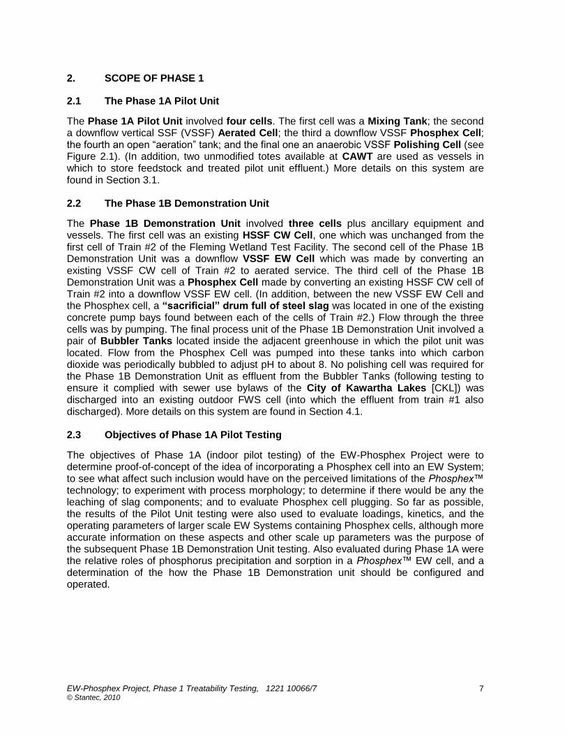
The Phase 1A Pilot Unit involved four cells. The first cell was a Mixing Tank; the second a downflow vertical SSF (VSSF) Aerated Cell; the third a downflow VSSF Phosphex Cell; the fourth an open “aeration” tank; and the final one an anaerobic VSSF Polishing Cell (see Figure 2.1). (In addition, two unmodified totes available at CAWT are used as vessels in which to store feedstock and treated pilot unit effluent.) More details on this system are found in Section 3.1. 2.2 The Phase 1B Demonstration Unit
The Phase 1B Demonstration Unit involved three cells plus ancillary equipment and vessels. The first cell was an existing HSSF CW Cell, one which was unchanged from the first cell of Train #2 of the Fleming Wetland Test Facility. The second cell of the Phase 1B Demonstration Unit was a downflow VSSF EW Cell which was made by converting an existing VSSF CW cell of Train #2 to aerated service. The third cell of the Phase 1B Demonstration Unit was a Phosphex Cell made by converting an existing HSSF CW cell of Train #2 into a downflow VSSF EW cell. (In addition, between the new VSSF EW Cell and the Phosphex cell, a “sacrificial” drum full of steel slag was located in one of the existing concrete pump bays found between each of the cells of Train #2.) Flow through the three cells was by pumping. The final process unit of the Phase 1B Demonstration Unit involved a pair of Bubbler Tanks located inside the adjacent greenhouse in which the pilot unit was located. Flow from the Phosphex Cell was pumped into these tanks into which carbon dioxide was periodically bubbled to adjust pH to about 8. No polishing cell was required for the Phase 1B Demonstration Unit as effluent from the Bubbler Tanks (following testing to ensure it complied with sewer use bylaws of the City of Kawartha Lakes [CKL]) was discharged into an existing outdoor FWS cell (into which the effluent from train #1 also discharged). More details on this system are found in Section 4.1. 2.3 Objectives of Phase 1A Pilot Testing
The objectives of Phase 1A (indoor pilot testing) of the EW-Phosphex Project were to determine proof-of-concept of the idea of incorporating a Phosphex cell into an EW System; to see what affect such inclusion would have on the perceived limitations of the Phosphex™ technology; to experiment with process morphology; to determine if there would be any the leaching of slag components; and to evaluate Phosphex cell plugging. So far as possible, the results of the Pilot Unit testing were also used to evaluate loadings, kinetics, and the operating parameters of larger scale EW Systems containing Phosphex cells, although more accurate information on these aspects and other scale up parameters was the purpose of the subsequent Phase 1B Demonstration Unit testing. Also evaluated during Phase 1A were the relative roles of phosphorus precipitation and sorption in a Phosphex™ EW cell, and a determination of the how the Phase 1B Demonstration unit should be configured and operated.
EW-Phosphex Project, Phase 1 Treatability Testing, 1221 10066/7 © Stantec, 2010
8
2.4 Objectives of Phase 1B Demonstration Testing
The objectives of Phase 1B (outdoor demonstration testing) of the EW-Phosphex Project were to scale up an EW-Phosphex System using the lessons learned during Phase 1A, and to assesses operating parameters and kinetics associated with the larger scale operations. It was also an objective of Phase 1B to assemble enough information to allow the design of a full-scale Phase 2 EW-Phosphex system for installation somewhere in the Lake Simcoe watershed. Influent flow rates for Phase 1B were two orders of magnitude higher than those for Phase 1A (i.e., several m3/d vs tens of liters per day). 2.5 Feedstock for Phase 1
The feedstock for both the EW-Phosphex Phase 1A Pilot Unit and the Phase 1B Demonstration Unit was human sewage generated in the recently-constructed (2005) Discovery Trail Wing of the College’s Frost Campus. Sewage and greywater from the restrooms of this wing is directed into a holding tank which provides a source of feedstock to one of the two trains of the CAWT Fleming Wetland Test Facility. (This train is the one converted to the Phase 1B Demonstration unit. The other train treats process water from a nearby aquaculture operation.) Wastewater from the holding tank is first directed through a holding (septic) tank located immediately upstream of the outdoor CAWT wetlands. All wastewater passing through the units was eventually deposited to a sanitary sewer after ensuring that monitored parameters such as pH and metal concentrations met the sanitary sewer by-law requirements of CKL. 2.6 Substrate for Phase 1
The steel slag media used in both of the Phosphex™ EW cells was that from a Basic Oxygen Furnace (BOF) at the Stelco steel mill in Hamilton, ON and was provided by the UofW. (See Appendix E in accompanying Volume 2.) The substrate had been stored outdoors for some time at the site of an aggregate supplier and was screened and washed before being shipped to the College. (Nevertheless, the slag still contained some lime.)

EW-Phosphex Project, Phase 1 Treatability Testing, 1221 10066/7 © Stantec, 2010
9
3. DESIGN AND CONSTRUCTION OF THE PHASE 1A PILOT UNIT
3.1 Phase 1A Pilot Unit Layout
The cells of the Phase 1A Pilot Unit were constructed using refurbished chemical totes. During the development of the EW ecotechnology in the late 1990s, Stantec predecessor, Jacques Whitford, showed that EW operation could be simulated in treatability tests involving pilot- and/or demonstration-scale facilities, and that these could be used to determine needed kinetics and other parameters necessary for designing full-scale EWs (Higgins, 1997, IRAP, 1999). It was also determined then that one cubic metre indoor EW cells usually gave much the same kinetic results as much larger outdoor demonstration-scale EW cells, and allowed better control of environmental factors. The kind of chemical totes used for pilot unit cells have an internal plastic liner in a steel support cage and have an outlet valve located at the bottom of the tote. They are 1040 liters in size when full. (See Appendix D.10 of in accompanying Volume 2 for more details on treatability testing.) The supplied totes had been pressure tested and washed prior to delivery. Using a design prepared by Stantec, Nature Works constructed the cells of the Phase 1A pilot-scale EW System at a Stantec geotechnical laboratory in Burlington, ON. The finished EW cells were then transported to the College in Lindsay Ontario where their substrates were added and the cells connected together by Nature Works and CAWT staff. The Phase 1A Pilot Unit involved an initial Mixing Tank and four other cells: a downflow vertical SSF (VSSF) Aerated Cell; a downflow VSSF Phosphex Cell; an open gas contact tank (the Open Tank), and a final, anaerobic VSSF Polishing Cell. (In addition, two unmodified totes are used as vessels in which to store feedstock and treated pilot unit effluent.) The following picture shows the Fleming Pilot Unit at the CAWT facilities located in a greenhouse at the College with the initial sewage storage vessel (an un-modified tote) in the foreground with Mixing Tank beside it on the right, the Aerated Cell behind it (vegetation just showing), the Phosphex Cell (un-vegetated) in the middle, and the final vegetated Polishing Cell with the Open Tank beside it. Picture 3.1: A View of the EW-Phosphex Pilot Unit

EW-Phosphex Project, Phase 1 Treatability Testing, 1221 10066/7 © Stantec, 2010
10
The same configuration was used to connect each of the cells, as is shown in the following picture (also see Picture 3.7). Picture 3.2: Delivery Matrix as Constructed Between Pilot Unit Cells
The above photo shows configuration for gravity feed with provision for the attachment of a peristaltic pump between the Phase 1A cells. A sampling valve is also visible. Figures 3.2 and 3.3 (next two pages) show the configurations of the inlet and outlet distributors, while Picture 3.3 shows an actual outlet matrix in a cell bottom. Picture 3.3: Outlet Distribution Matrix in Phase 1A EW Cell Bottom
Sampling Valve
Gravity Flow Shut -off Valve

EW-Phosphex Project, Phase 1 Treatability Testing, 1221 10066/7 © Stantec, 2010
11
Figure 3.1: Design of Phase 1A Pilot EW Cell Inlet Distribution Matrix
Perforated Pipe

EW-Phosphex Project, Phase 1 Treatability Testing, 1221 10066/7 © Stantec, 2010
12
Figure 3.2: Design of Phase 1A Pilot EW Cell Outlet Distribution Matrix
Perforated Pipe
Perforated Pipe
Perforated Pipe

EW-Phosphex Project, Phase 1 Treatability Testing, 1221 10066/7 © Stantec, 2010
13
Picture 3.4 shows the “topping” of a tote, while Picture 3.5 shows one after its top was removed. Picture 3.4: Removing the Top from a Chemical Tote
Picture 3.5: A Tote with Its Top Removed to Allow Its Use as a Test Cell

EW-Phosphex Project, Phase 1 Treatability Testing, 1221 10066/7 © Stantec, 2010
14
Each cell was elevated above the previous one but in addition piping was installed so that wastewater could be pumped between the cells using peristaltic pumps should this prove necessary. (It did not.) The Pilot Unit test cells were placed so that flow through them was by gravity. The Mixing Tank was raised on eight inch concrete blocks placed at each of the four corners. The Pilot Unit Aerated EW cell was set on blocks of wood to give a 3½ inch drop. The Phosphex Cell was raised by 1½ inches using wooden blocks, as was the Open Tank cell. The final Polishing Cell was on the greenhouse‟s concrete floor. As was mentioned, two additional totes made up Phase 1A Pilot Unit: a storage vessel placed in front of the Mixing Tank holding the sewage feedstock and a final storage vessel to hold treated wastewater. The following picture shows piping between two of the pilot units cells.
Picture 3.6: Piping Connections between Phase 1A Pilot EW Cells
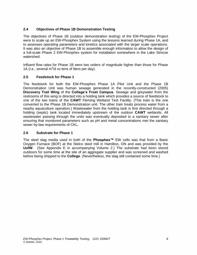
The following picture shows all three EW cells in place at the College (also see Picture 3.10).
EW-Phosphex Project, Phase 1 Treatability Testing, 1221 10066/7 © Stantec, 2010
15
Picture 3.7: All Phase 1A Pilot EW Cells in Place at Fleming College
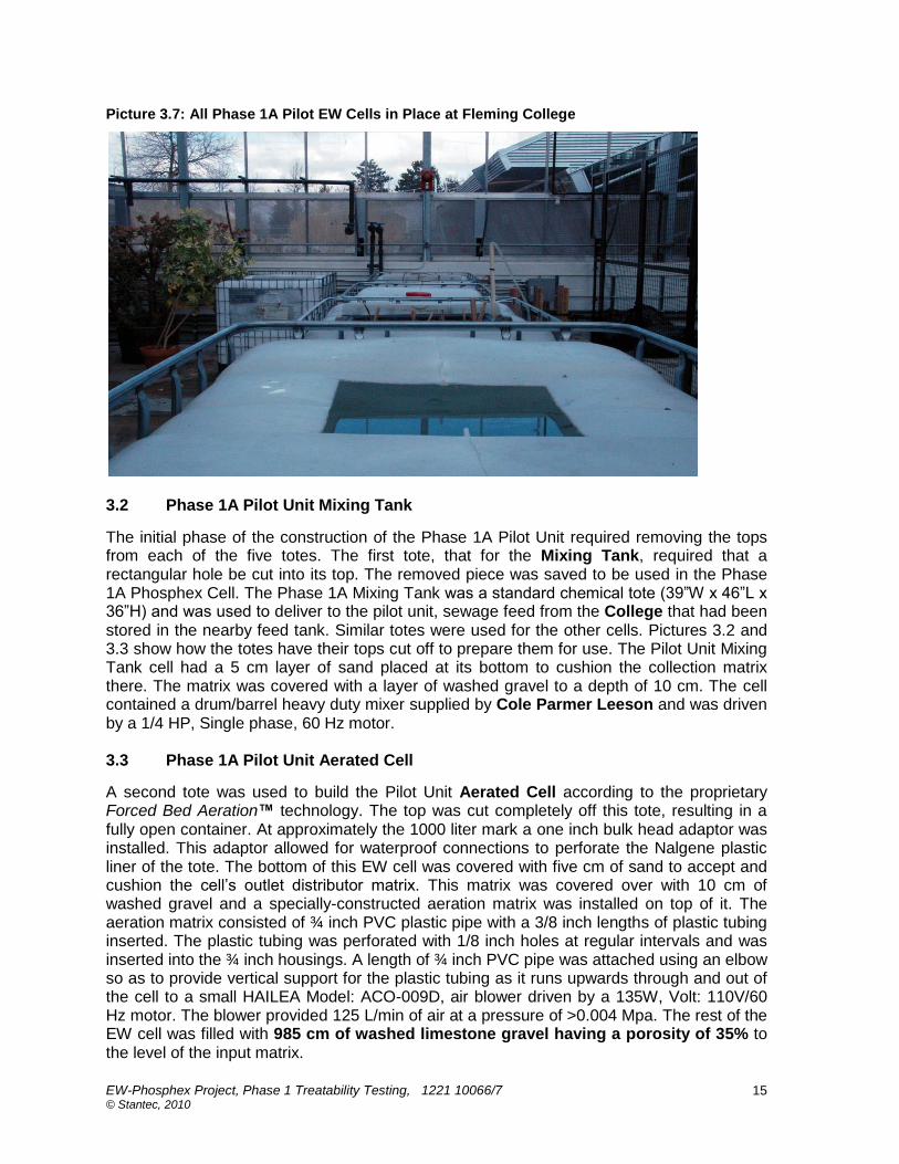
3.2 Phase 1A Pilot Unit Mixing Tank
The initial phase of the construction of the Phase 1A Pilot Unit required removing the tops from each of the five totes. The first tote, that for the Mixing Tank, required that a rectangular hole be cut into its top. The removed piece was saved to be used in the Phase 1A Phosphex Cell. The Phase 1A Mixing Tank was a standard chemical tote (39”W x 46”L x 36”H) and was used to deliver to the pilot unit, sewage feed from the College that had been stored in the nearby feed tank. Similar totes were used for the other cells. Pictures 3.2 and 3.3 show how the totes have their tops cut off to prepare them for use. The Pilot Unit Mixing Tank cell had a 5 cm layer of sand placed at its bottom to cushion the collection matrix there. The matrix was covered with a layer of washed gravel to a depth of 10 cm. The cell contained a drum/barrel heavy duty mixer supplied by Cole Parmer Leeson and was driven by a 1/4 HP, Single phase, 60 Hz motor. 3.3 Phase 1A Pilot Unit Aerated Cell
A second tote was used to build the Pilot Unit Aerated Cell according to the proprietary Forced Bed Aeration™ technology. The top was cut completely off this tote, resulting in a fully open container. At approximately the 1000 liter mark a one inch bulk head adaptor was installed. This adaptor allowed for waterproof connections to perforate the Nalgene plastic liner of the tote. The bottom of this EW cell was covered with five cm of sand to accept and cushion the cell‟s outlet distributor matrix. This matrix was covered over with 10 cm of washed gravel and a specially-constructed aeration matrix was installed on top of it. The aeration matrix consisted of ¾ inch PVC plastic pipe with a 3/8 inch lengths of plastic tubing inserted. The plastic tubing was perforated with 1/8 inch holes at regular intervals and was inserted into the ¾ inch housings. A length of ¾ inch PVC pipe was attached using an elbow so as to provide vertical support for the plastic tubing as it runs upwards through and out of the cell to a small HAILEA Model: ACO-009D, air blower driven by a 135W, Volt: 110V/60 Hz motor. The blower provided 125 L/min of air at a pressure of >0.004 Mpa. The rest of the EW cell was filled with 985 cm of washed limestone gravel having a porosity of 35% to the level of the input matrix.
EW-Phosphex Project, Phase 1 Treatability Testing, 1221 10066/7 © Stantec, 2010
16
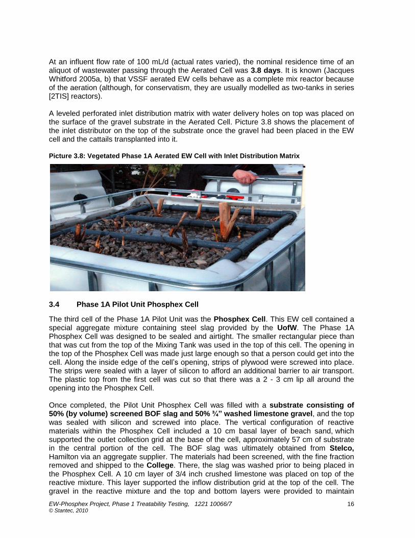
At an influent flow rate of 100 mL/d (actual rates varied), the nominal residence time of an aliquot of wastewater passing through the Aerated Cell was 3.8 days. It is known (Jacques Whitford 2005a, b) that VSSF aerated EW cells behave as a complete mix reactor because of the aeration (although, for conservatism, they are usually modelled as two-tanks in series [2TIS] reactors). A leveled perforated inlet distribution matrix with water delivery holes on top was placed on the surface of the gravel substrate in the Aerated Cell. Picture 3.8 shows the placement of the inlet distributor on the top of the substrate once the gravel had been placed in the EW cell and the cattails transplanted into it. Picture 3.8: Vegetated Phase 1A Aerated EW Cell with Inlet Distribution Matrix
3.4 Phase 1A Pilot Unit Phosphex Cell
The third cell of the Phase 1A Pilot Unit was the Phosphex Cell. This EW cell contained a special aggregate mixture containing steel slag provided by the UofW. The Phase 1A Phosphex Cell was designed to be sealed and airtight. The smaller rectangular piece than that was cut from the top of the Mixing Tank was used in the top of this cell. The opening in the top of the Phosphex Cell was made just large enough so that a person could get into the cell. Along the inside edge of the cell‟s opening, strips of plywood were screwed into place. The strips were sealed with a layer of silicon to afford an additional barrier to air transport. The plastic top from the first cell was cut so that there was a 2 - 3 cm lip all around the opening into the Phosphex Cell. Once completed, the Pilot Unit Phosphex Cell was filled with a substrate consisting of 50% (by volume) screened BOF slag and 50% ¾” washed limestone gravel, and the top was sealed with silicon and screwed into place. The vertical configuration of reactive materials within the Phosphex Cell included a 10 cm basal layer of beach sand, which supported the outlet collection grid at the base of the cell, approximately 57 cm of substrate in the central portion of the cell. The BOF slag was ultimately obtained from Stelco, Hamilton via an aggregate supplier. The materials had been screened, with the fine fraction removed and shipped to the College. There, the slag was washed prior to being placed in the Phosphex Cell. A 10 cm layer of 3/4 inch crushed limestone was placed on top of the reactive mixture. This layer supported the inflow distribution grid at the top of the cell. The gravel in the reactive mixture and the top and bottom layers were provided to maintain
EW-Phosphex Project, Phase 1 Treatability Testing, 1221 10066/7 © Stantec, 2010
17
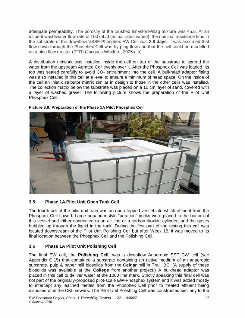
adequate permeability. The porosity of the crushed limestone/slag mixture was 45.5. At an influent wastewater flow rate of 100 mL/d (actual rates varied), the nominal residence time in the substrate of the downflow VSSF Phosphex EW Cell was 2.8 days. It was assumed that flow down through the Phosphex Cell was by plug flow and that the cell could be modelled as a plug flow reactor (PFR) (Jacques Whitford, 2005a, b). A distribution network was installed inside the cell on top of the substrate to spread the water from the upstream Aerated Cell evenly over it. After the Phosphex Cell was loaded, its top was sealed carefully to avoid CO2 entrainment into the cell. A bulkhead adaptor fitting was also installed in this cell at a level to ensure a minimum of head space. On the inside of the cell an inlet distributor matrix similar in design to those in the other cells was installed. The collection matrix below the substrate was placed on a 10 cm layer of sand, covered with a layer of washed gravel. The following picture shows the preparation of the Pilot Unit Phosphex Cell. Picture 3.9: Preparation of the Phase 1A Pilot Phosphex Cell
3.5 Phase 1A Pilot Unit Open Tank Cell
The fourth cell of the pilot unit train was an open-topped vessel into which effluent from the Phosphex Cell flowed. Large aquarium-style “aeration” pucks were placed in the bottom of this vessel and either connected to an air line or a carbon dioxide cylinder, and the gases bubbled up through the liquid in the tank. During the first part of the testing this cell was located downstream of the Pilot Unit Polishing Cell but after Week 15, it was moved to its final location between the Phosphex Cell and the Polishing Cell. 3.6 Phase 1A Pilot Unit Polishing Cell
The final EW cell, the Polishing Cell, was a downflow Anaerobic SSF CW cell (see Appendix C.15) that contained a substrate containing an active medium of an anaerobic substrate, pulp & paper mill biosolids from the Celgar mill in Trail, BC. (A supply of these biosolids was available at the College from another project.) A bulkhead adaptor was placed in this cell to deliver water at the 1000 liter mark. Strictly speaking this final cell was not part of the originally-proposed pilot-scale EW-Phosphex system and it was added mostly to intercept any leached metals from the Phosphex Cell prior to treated effluent being disposed of in the CKL sewers. The Pilot Unit Polishing Cell was constructed similarly to the

EW-Phosphex Project, Phase 1 Treatability Testing, 1221 10066/7 © Stantec, 2010
18
Aerated Cell but without the aeration matrix. Its bottom outlet distribution matrix was installed the same as for that cell – five cm of sand, the matrix, then 10 cm of gravel. The first 500 mm thick layer of substrate above the outlet distribution matrix of the Polishing Cell was a mixture composed of seven parts of biosolids to five parts of gravel and two parts of sand. Above this was a 250 mm thick layer of substrate that consisted of seven parts of biosolids to 12 parts of gravel and two parts of sand. Finally a 250 mm thick layer of unwashed gravel was placed on top to bring the total substrate volume to 1000 liters. Assuming an average porosity of about 30%, the nominal residence time in the 1000 mm of various substrates in the Polishing Cell for a wastewater rate of 100mL/d (actual rates varied) was about 4.3 days and it was assumed that plug flow reaction kinetics were applicable in it. A leveled outlet distribution matrix with the holes on top was placed on top of the substrate. The following picture shows the assembled Phase 1A Pilot Unit before acclimatization and operations commenced. Picture 3.10: Side View of Assembled Phase 1A EW-Phosphex Pilot Unit
EW-Phosphex Project, Phase 1 Treatability Testing, 1221 10066/7 © Stantec, 2010
19
4. DESIGN AND MODIFICATION OF THE PHASE 1B DEMONSTRATION UNIT
4.1 The Fleming Wetland Test Facility
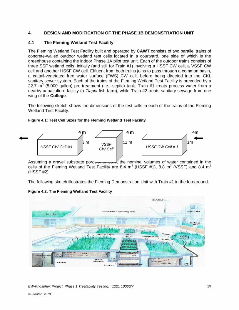
The Fleming Wetland Test Facility built and operated by CAWT consists of two parallel trains of concrete-walled outdoor wetland test cells located in a courtyard, one side of which is the greenhouse containing the indoor Phase 1A pilot test unit. Each of the outdoor trains consists of three SSF wetland cells, initially (and still for Train #1) involving a HSSF CW cell, a VSSF CW cell and another HSSF CW cell. Effluent from both trains joins to pass through a common basin, a cattail-vegetated free water surface (FWS) CW cell, before being directed into the CKL sanitary sewer system. Each of the trains of the Fleming Wetland Test Facility is preceded by a 22.7 m3 (5,000 gallon) pre-treatment (i.e., septic) tank. Train #1 treats process water from a nearby aquaculture facility (a Tlapia fish farm), while Train #2 treats sanitary sewage from one wing of the College. The following sketch shows the dimensions of the test cells in each of the trains of the Fleming Wetland Test Facility. Figure 4.1: Test Cell Sizes for the Fleming Wetland Test Facility
4 m 4 m 4m 1.2 m 2.1 m 1m 5 m 3 m 6 m Assuming a gravel substrate porosity of 35%, the nominal volumes of water contained in the cells of the Fleming Wetland Test Facility are 8.4 m3 (HSSF #1), 8.8 m3 (VSSF) and 8.4 m3 (HSSF #2). The following sketch illustrates the Fleming Demonstration Unit with Train #1 in the foreground. Figure 4.2: The Fleming Wetland Test Facility
VSSF
CW Cell
HSSF CW Cell l#1
HSSF CW Cell # 1

EW-Phosphex Project, Phase 1 Treatability Testing, 1221 10066/7 © Stantec, 2010
20
After HSSF cell #2, and between each of the HSSF cells and the VSSF cell of each train of the Fleming Wetland Test Facility are 120 cm wide, 100 cm long and 170 cm deep covered, concrete pump chambers into which piping from the cells penetrate. When used as a tank, water depth in one of a chamber‟s three vaults fluctuates between 30 and 50 cm. Pumps, piping and instruments for the test facility are located in these chambers, as well as bypass piping. Picture 4.1 shows the chamber in front of the first cell of Train #2 of the Fleming Wetland Test Facility (the HSSF CW Cell of the Demonstration Unit) with access vaults for the buried holding tank further back. Picture 4.1: Pump Chamber at Fleming Wetland Test Facility
4.2 The Phase 1B Demonstration Unit
The Demonstration Unit for Phase 1B was made by modifying Train # 2 of the Fleming Wetland Test Facility, converting it into an EW System. For this conversion, the first HSSF CW cell of Train #2 was left as is, while the VSSF CW cell was converted into an aerated VSSF EW Cell, and the second HSSF CW cell converted into a sealed, downflow VSSF Phosphex Cell. A final polishing cell was not included in the Phase 1B Demonstration Unit morphology. Alkaline effluent from the Phosphex Cell was pumped into one of two open Bubbler Tanks inside the nearby greenhouse where pH was adjusted and treated wastewater stored prior to discharge via the common outdoor FWS CW cell before disposal into a CKL sewer. More details on the Phase 1B Demonstration Unit are found in Section 6.

EW-Phosphex Project, Phase 1 Treatability Testing, 1221 10066/7 © Stantec, 2010
21
4.3 The Phase 1B HSSF CW Cell
As was mentioned, this first HSSF CW cell was left as it was and served only to provide some minor pre-treatment and to protect the downstream Aerated Cell from any solids carryover from the holding tank. Effluent was pumped from the outlet of the HSSF CW cell into the downstream Aerated Cell using a 4/10 HP ME40 PC-1 Meyers sump pump located in the pump chamber between the two cells. 4.4 The Phase 1B Aerated VSSF EW Cell
Construction of the Phase 1B Demonstration Unit commenced on October 10, 2009 with the removal of the plants and inlet piping from the top of the Fleming Wetland Test Unit‟s Train #2 VSSF CW cell, followed by the removal of the cell‟s gravel substrate to expose its outlet piping, which was removed and replaced. The total depth of the cell was 224 cm. Picture 4.2 shows the emptied cell after new outlet piping was installed. Picture 4.2: Empty Phase 1B Demonstration Unit Aerated Cell
At this point, 28 cm of ¾” washed crushed granite gravel was placed over the 4” dia. outlet distributors, covering them, and perforated aeration tubing, provided as an in-kind contribution by Nelson, was placed on top of the gravel as shown in the following Picture 4.3 and illustrated in Figure 4.3.

EW-Phosphex Project, Phase 1 Treatability Testing, 1221 10066/7 © Stantec, 2010
22
Picture 4.3: Aeration Tubing Being Placed in the Bottom of the Aerated Cell
Figure 4.3: Aerated Cell Aeration System Design
EW-Phosphex Project, Phase 1 Treatability Testing, 1221 10066/7 © Stantec, 2010
23
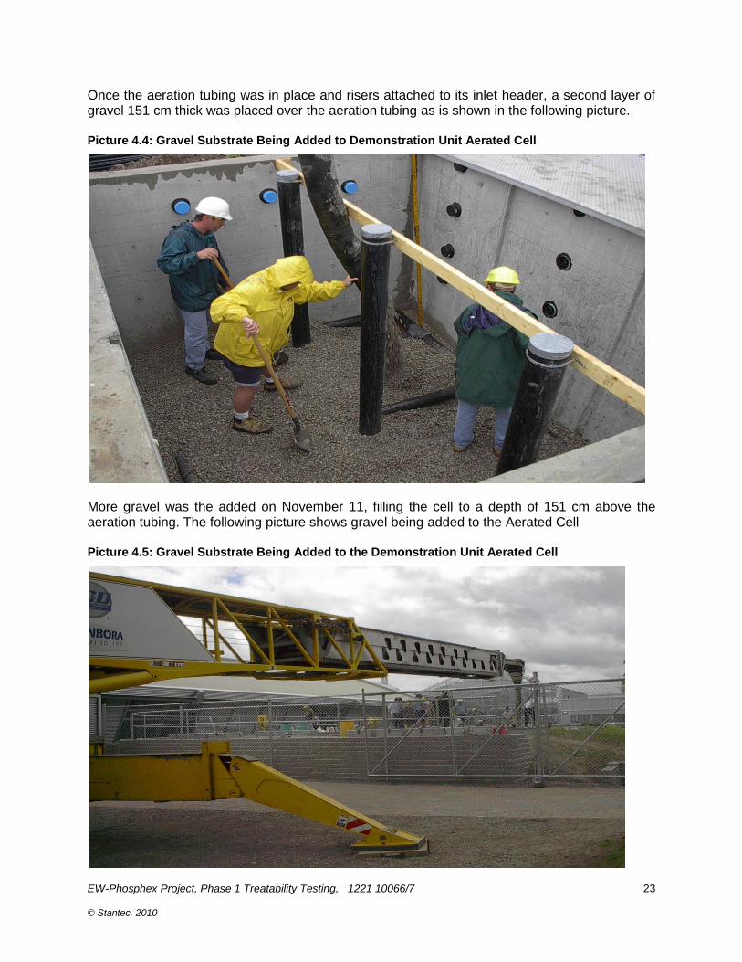
Once the aeration tubing was in place and risers attached to its inlet header, a second layer of gravel 151 cm thick was placed over the aeration tubing as is shown in the following picture. Picture 4.4: Gravel Substrate Being Added to Demonstration Unit Aerated Cell
More gravel was the added on November 11, filling the cell to a depth of 151 cm above the aeration tubing. The following picture shows gravel being added to the Aerated Cell Picture 4.5: Gravel Substrate Being Added to the Demonstration Unit Aerated Cell

EW-Phosphex Project, Phase 1 Treatability Testing, 1221 10066/7 © Stantec, 2010
24
Once the Aerated Cell was full of gravel, a two inch dia inlet distribution grid (matrix) was placed on top of the smoothed and leveled gravel as is shown in the following picture. Picture 4.6: Inlet Distribution Matrix on Top of Phase 1B Aerated Cell
The inlet distribution grid had holes drilled in its top, was carefully levelled and had water pumped through them to ensure the even dispensing of influent. Picture 4.7 shows one arm of the inlet distribution grid of the Aerated Cell lying on the substrate surface. The picture depicts the cell in operation with water seeping from the drilled holes and air bubbling up to the substrate surface from the aeration tubing buried below it, 1.5m down. Picture 4.7: Aerated Cell Inlet Distributor Operation
As the following picture illustrates, each arm of the grid had a piece of heating tape strapped beside it to prevent freezing in cold weather.

EW-Phosphex Project, Phase 1 Treatability Testing, 1221 10066/7 © Stantec, 2010
25
Picture 4.8: Inlet Distributors Were Heat-Traced
Aeration air for the Aerated cell was provided by four1/8 HP 917 Series Diaphragm air blowers (~ 1 CFM @ 0 psig) which were located in one of the bays of the pump chamber between the Demonstration Unit‟s HSSF CW Cell and its Aerated Cell as is shown below. Picture 4.9: Demonstration Unit Air Blowers
Normally for aerated VSSF EW cells a layer of insulating mulch is placed on the inlet distribution grid to wick influent to the cell (such as done for the Pilot Unit‟s aerated cell – see Picture 3.7). However it was decided not to use wicking mulch on the surface of the Demonstration Unit‟s Aerated Cell and for this vessel, the reeds which had been removed earlier were re-planted between the arms of the grid. The cell was then covered with 45 cm of insulating straw. The following sketch illustrates the morphology of the Aerated Cell.

EW-Phosphex Project, Phase 1 Treatability Testing, 1221 10066/7 © Stantec, 2010
26
Figure 4.4: Sketch of Demonstration Unit Aerated Cell
As may be seen, the total depth of gravel substrate to the normal water level 4 cm below the gravel surface was 175 cm (28 +147). (Since a Forced Bed Aeration™ EW cell acts as a complete mix reactor, the volume below the aeration grid and outlet pipes will also be “active”, so this is the nominal substrate thickness for the Aerated Cell.) 4.5 The Phase 1B Demonstration Unit’s Sacrificial Slag Drum
Although every precaution was taken to exclude air from the Demonstration Unit‟s Phosphex Cell, and aeration in the Aerated Cell was expected to degasify effluent from the upstream Aerated Cell (removing any dissolved CO2), the feedstock to it would still contain enough bicarbonates so that some tufa (calcium carbonate) could form when the feedwater first encountered steel slag. To allow for this effect (which might otherwise plug the inlet of the Phosphex Cell), a 200 L drum full of the same steel slag used as substrate in the Phosphex Cell was located in one of the vaults of the chamber between the Aerated Cell and the Phosphex Cell, and effluent from the Aerated Cell was first passed through this easily maintainable vessel before it entered the Phosphex Bell. The following picture shows this sacrificial drum of steel slag in operation.
224 cm
Saturation zone is approx 147 cm above aeration grid (approx 17.6 m
3)
Gravel substrate is 151 cm deep above aeration grid
Influent distribution grid directly on top of granite (reeds planted between rows of gridwork)
Aeration grid directly on gravel layer
Aerated VSSF EW Cell
45 cm with insulating straw
Top of gravel (151 cm deep)
4” collection pipe

EW-Phosphex Project, Phase 1 Treatability Testing, 1221 10066/7 © Stantec, 2010
27
Picture 4.10: Sacrificial Slag Drum
Aerated Cell effluent enters the barrel of steel slag at the top and exists into the vault via small holes drilled in the side of the barrel. From there it is pumped into the downstream Phosphex Cell. 4.6 The Phase 1B Demonstration Unit’s Phosphex Cell
The Demonstration Unit‟s Phosphex Cell was prepared by removing the gravel and piping from the 150 cm deep second HSSF CW cell of Train #2 of the Fleming Wetland Test Unit. Once this was complete a new set of three perforated outlet collection pipes was laid in the bottom of the cell. Picture 4.10 shows this piping along with its clean out risers. Picture 4.11: Phase 1B Phosphex Cell Outlet Collection Piping on Cell Floor
EW-Phosphex Project, Phase 1 Treatability Testing, 1221 10066/7 © Stantec, 2010
28
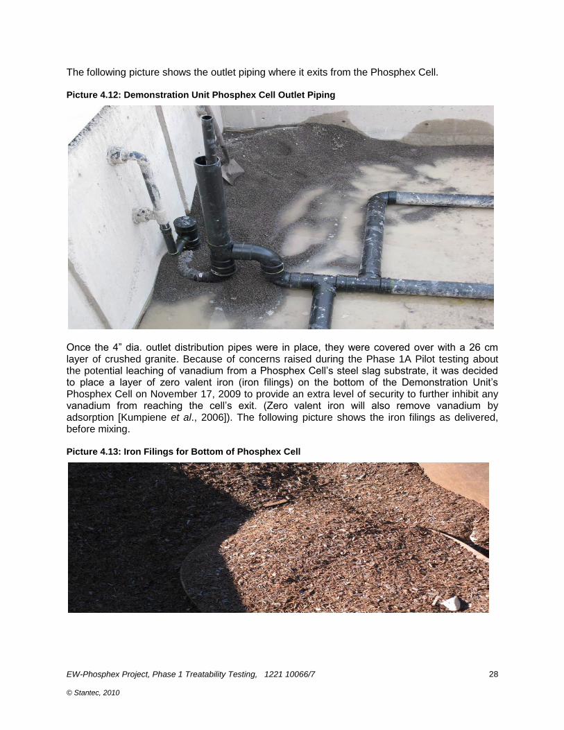
The following picture shows the outlet piping where it exits from the Phosphex Cell. Picture 4.12: Demonstration Unit Phosphex Cell Outlet Piping
Once the 4” dia. outlet distribution pipes were in place, they were covered over with a 26 cm layer of crushed granite. Because of concerns raised during the Phase 1A Pilot testing about the potential leaching of vanadium from a Phosphex Cell‟s steel slag substrate, it was decided to place a layer of zero valent iron (iron filings) on the bottom of the Demonstration Unit‟s Phosphex Cell on November 17, 2009 to provide an extra level of security to further inhibit any vanadium from reaching the cell‟s exit. (Zero valent iron will also remove vanadium by adsorption [Kumpiene et al., 2006]). The following picture shows the iron filings as delivered, before mixing. Picture 4.13: Iron Filings for Bottom of Phosphex Cell

EW-Phosphex Project, Phase 1 Treatability Testing, 1221 10066/7 © Stantec, 2010
29
As is shown in the following picture, the iron filings (about 0.5 m3) were raked out into an even layer above the gravel covering the outlet pipes. Picture 4.14: Iron Filings Being Placed at Bottom of Phosphex Cell
An attempt was made to work the iron filings into the gravel but this was possible for only a shallow layer of 5 -10 cm on top of it. The following picture shows the iron filings among the steel slag. Picture 4.15: Iron Filings among Gravel Particles

EW-Phosphex Project, Phase 1 Treatability Testing, 1221 10066/7 © Stantec, 2010
30
Once the layer of iron filings had been raked out on the surface of the gravel layer, about 55 cm of steel slag (~13.2 m3) was added to the Phosphex Cell. The surface was then leveled and an influent distribution matrix similar to that used on the upstream Aerated Cell was then placed on the leveled surface. Picture 4.10 (next page) shows the two inch diameter inlet distribution grid being placed. The saturation zone is set to the top of the slag by use of a standpipe (not shown in picture below). Picture 4.16: Demonstration Unit Phosphex Cell Inlet Distribution Grid
The following picture shows the connection of the Phosphex Cell inlet grid to the pipe from the feed pump in the upstream chamber. Picture 4.17: Connection of Phosphex Cell Inlet Distribution Grid

EW-Phosphex Project, Phase 1 Treatability Testing, 1221 10066/7 © Stantec, 2010
31
As is shown in the following picture, the inlet distribution grid on top of the slag was then covered over with 29 cm (3.5 m3) of crushed gravel, „sandwiching” it between the slag and the gravel. The reason for the additional granite was to ensure that the depth of the granite/slag/granite layer would be sufficient to ensure that an overlying tarp and sand layer were above the fixed outlet of the cell. The extra gravel on top of the slag ensured that the entire bed of slag was completely saturated, without concerns that the water level might flood out into the overtopping layer of sand. Picture 4.18: Covering Phosphex Cell Inlet Distribution Grid with Gravel
Once the gravel layer was in place, a tarp was placed over the top of the cell to seal and isolate it. Duct tape was used to seal around any protruding pipes (e.g., outlet distribution grid cleanout risers). Picture 4.13 shows the tarp over the top of the Phase 1B Phosphex Cell. Picture 4.19: Tarp over Demonstration Unit Phosphex Cell

EW-Phosphex Project, Phase 1 Treatability Testing, 1221 10066/7 © Stantec, 2010
32
As shown in the following picture, the tarp was held in place with a 17 cm layer of washed sand. Picture 4.20: Sand Placed over Phosphex Cell Tarp
A layer of straw (varying in thickness from 1 to 2 bales thick – to follow sloping contour of the sides of the concrete) was added primarily to ensure that a second larger tarp would cover the entire cell and not have any sagging areas where rain occurred. The layer between the two tarps was separately drained to prevent contamination of the Phosphex Cell with rainwater. The following picture shows the completed, tarp-covered Phosphex Cell. Picture 4.21: Completed Demonstration Unit Phosphex Cell
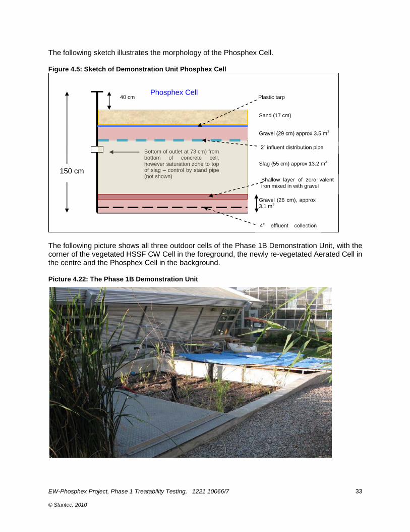
EW-Phosphex Project, Phase 1 Treatability Testing, 1221 10066/7 © Stantec, 2010
33
The following sketch illustrates the morphology of the Phosphex Cell. Figure 4.5: Sketch of Demonstration Unit Phosphex Cell
The following picture shows all three outdoor cells of the Phase 1B Demonstration Unit, with the corner of the vegetated HSSF CW Cell in the foreground, the newly re-vegetated Aerated Cell in the centre and the Phosphex Cell in the background. Picture 4.22: The Phase 1B Demonstration Unit
150 cm
Gravel (26 cm), approx 3.1 m
3
Slag (55 cm) approx 13.2 m3
Gravel (29 cm) approx 3.5 m3
Sand (17 cm)
Plastic tarp
Bottom of outlet at 73 cm) from bottom of concrete cell, however saturation zone to top of slag – control by stand pipe (not shown)
Phosphex Cell 40 cm
Shallow layer of zero valent iron mixed in with gravel
4” effluent collection pipe
2” influent distribution pipe

EW-Phosphex Project, Phase 1 Treatability Testing, 1221 10066/7 © Stantec, 2010
34
4.7 Phase 1B CO2 Bubbler Tanks
Effluent from the Phosphex cell was pumped into the nearby CAWT greenhouse (the same one in which the Phase 1A Pilot Unit was located) into tow 1000 L plastic tanks (Picture 4.17, the CO2 Bubbler Tanks) into which carbon dioxide gas was added. Picture 4.23: CO2 Bubbler Tanks
Carbon dioxide addition to the Bubbler Tanks was controlled by an Intermatic Model 1105C timer (Picture 4.18) which for 20 minutes at midnight, 4AM, 8AM, noon, 2PM, 4PM, and 8PM operated a solenoid valve to control injection. The time was set to maintain the pH of effluent in the Bubbler tanks in the 8 range. Picture 4.24: CO2 Addition Timer

EW-Phosphex Project, Phase 1 Treatability Testing, 1221 10066/7 © Stantec, 2010
35
CO2 flow was measured by the flowmeter shown in the following picture. Picture 4.25: CO2 Flow Meter
Carbon dioxide was deployed into the Bubbler Tanks using an “air curtain” bubbler, one similar to those used for drip line irrigation. 100% CO2 flow was intermittent but averaged one litre every 46 seconds for the first Bubbler Tank (~235 L/d) and one litre every 99 seconds for the second tank (109 L/D). After testing for pH and other parameters covered under sewer use bylaws, neutralized water from the Bubbler tanks was discharged to the CKL sewer.

EW-Phosphex Project, Phase 1 Treatability Testing, 1221 10066/7 © Stantec, 2010
36
5. OPERATION OF THE PHASE 1A PILOT UNIT
5.1 Phase 1A Pilot Unit Process Flow
As was mentioned, the Phase 1A Pilot Unit involved an initial Mixing Tank and four other cells: a downflow vertical SSF (VSSF) Aerated Cell; a downflow VSSF Phosphex Cell; an open gas contact tank (the Open Tank), and a final, anaerobic VSSF Polishing Cell. The following figure shows a process flow diagram for the Pilot Unit at the start of the Phase 1A. Figure 5.1: Process Flow for the Phase 1A Pilot Unit
5.2 Schedule for Phase 1A Pilot Unit Operations
Phase 1A testing took place over an eight month period at ambient indoor temperatures during the latter part of 2009 and early 2010. The Aerated Cell and the Polishing Cell were vegetated with transplanted cattails (Typha spp.) collected from the outdoor demonstration unit. The Phosphex Cell was sealed and un-vegetated. Raw sewage and greywater were pumped from the aforementioned settling (septic) tank into a 1000 L plastic tote (identified as the feed tank) of the indoor EW-Phosphex Phase 1A Pilot Unit. The purpose of the feed tank was to provide a readily available supply of wastewater for the Pilot Unit. On average, this tank was filled once a week. Wastewater from the feed tank was pumped with the aid of a peristaltic pump into the Mixing Tank. The operation of the peristaltic pump was controlled by a timer which turned the pump on for a fifteen minute period every two hours. Wastewater flow started through the Phase 1A Pilot Unit in May 2009 and the first set of samples were taken the first week of June, 2009 (Week 1). The pH of Phosphex Cell outlet water remained in the high 10s and low 11s making it necessary to neutralize the effluent in order to lower it to below the pH limit of 10.5 dictated by the CKL sewer by-law for disposal. Air was aspirated through a bubbler located in final Holding Tank to try to reduce the pH of the final effluent to below the pH 10.5 by-law limit.
EW-Phosphex Project, Phase 1 Treatability Testing, 1221 10066/7 © Stantec, 2010
37
As was mentioned above, after Week 15 of the Phase 1A testing, a decision was made to move the Open Tank to between the Pilot Unit‟s Phosphex Cell and its Polishing Cell. This action was taken on the belief that a lower pH wastewater entering the Polishing Cell would enhance its performance, particularly in the removal of certain metals such as aluminum. During Weeks 15 and 16 of the Phase 1A testing, air was vigorously bubbled into the collected Phosphex Cell effluent in the Open Tank. However, the small amounts of CO2 in the air were not able to substantially reduce the pH to the desired level of 10.5. Thus in Week 16, the bubbled air was replaced with carbon dioxide gas (100% strength) from a compressed gas cylinder. This worked but because of the low wastewater flow rate through the pilot unit, there were initial difficulties in determining an appropriate CO2 addition rate, and at times the pH of the water in the Phase 1A Open Tank dropped below 6, the lower limit for sewer disposal. (I.e., 100% CO2 was too effective in reducing the pH of a stream that was only flowing at less than 100L/d). Because of this, a decision was made to bubble a gas mixture comprised of 10% CO2 and 90% air. However, with this option, the volume of gas required to reduce the pH from the mid to high 11s to approximately 7 to 8 was large, and this combined with the extra cost to obtain the custom gas mixture suggested that the use of the 100% CO2 mixture would be more practical. It then was determined that once the pH of the effluent in the Open Tank was reduced to near neutral, the pH range could be maintained with an approximately thirty minute bubbling per day of the 100% CO2 gas. (Controlling Phosphex Cell effluent pH was easier during the subsequent Demonstration Unit testing when feed flow rate was nearly 100X as much.) 5.3 Phase 1A Pilot Unit Operations
The duration of the Phase 1A pilot testing at Fleming College was about forty-two weeks, commencing the first week of June 2009 (Week 1) and ending the first week of February 2010 (Week 38). After an initial acclimatization and calibration period (approximately four weeks), the Phase 1A Pilot Unit operated 24 hours a day, seven days a week. Picture 5.1 (next page) shows the early growth of the wetland vegetation planted in the operating Aerated Cell and shows that that no visible inhibition of plant growth is occurring. (During part of the winter of 2009 – 2010, the plants in this cell and in the Polishing Cell went dormant, but this is normal for their growth patterns.) At the start of Phase 1A, once all cells were in place, connected and filled, the Aerated Cell and the Polishing Cell were filled with water, and spiked with raw sewage to inoculate them with microbes. Each was then vegetated with several transplanted cattails harvested from one of the cells of Train #1 of the Fleming Wetland Test Facility. The Phase 1A Pilot Unit cells were then allowed to acclimatize for a further two weeks (with the air on for the Aerated Cell). Weekly sampling of cell influents and effluents occurred and monitoring was for pH, dissolved oxygen, alkalinity, conductivity, cBOD5, COD, NH3-N, NO3-N, oPO4, TP, total coliforms, E. coli and metals were sampled by CAWT staff and were measured in adjacent CAWT laboratories at the College. Some parallel samples were taken by UofW staff for analyses at UoW and during Week 5 samples were sent to a third party testing lab (SGS Lakefield) for quality assurance/quality control purposes.

EW-Phosphex Project, Phase 1 Treatability Testing, 1221 10066/7 © Stantec, 2010
38
Picture 5.1 shows the cattails growing in the Aerated Cell early in Phase 1A. The layer of peat on the cell surface is there to wick the influent, ensuring its even distribution into the gravel substrate. Picture 5.1: Phase 1A Pilot Unit Aerated Cell in Operation
Picture 5.2 shows cattails growing in the Polishing Cell at about the same time. Growth for some time was reasonable despite the high pH of its influent (Phosphex Cell effluent) before the Open Tank was inserted between them and pH was controlled. Picture 5.2: Pilot Unit Polishing Cell Early During Phase 1A
The following picture (Picture 5.3) presents an overview of the entire operating pilot unit during its first week of operations. In the centre background is the storage vessel into which sewage from the College is collected. To the immediate left is the Mixing Tank (wooden board on top). Coming forward (downstream with regards to flow) is the Aerated Cell, with the cattails now growing well (compare to Figure 3.7 when they were first planted). The next in line is the Phosphex Cell. In the forefront of the photo on the left hand side is the Polishing Cell, and in the forefront on the right hand side is the Open Tank.
Cattail grow in vegetative VSSF A

EW-Phosphex Project, Phase 1 Treatability Testing, 1221 10066/7 © Stantec, 2010
39
Picture 5.3: The Phase 1A EW-Phosphex Pilot Unit during Early Operations
The following table lists volume measurements in the pilot unit during the Phase 1A testing. Table 5.1: Pilot Unit Wastewater Flows
Date Volume
prior
Volume after
Volume
Volume
to filling
fillling
Added since
used since
(L)
(L)
last filling
last filling
05-Jun-09
1080 09-Jun-09 388
1080
692
692
18-Jun-09 395
1080
685 25-Jun-09 312
1090
778
768
03-Jul-09 288
1120
832
802
10-Jul-09 400
1020
620
720
17-Jul-09 374
1105
731
646
24-Jul-09 400
600
200
705
28-Jul-09 228
1080
852
372
04-Aug-09 248
1100
852
832
06-Aug-09 725
did not add today 10-Aug-09 238
1075
837
862
14-Aug-09
did not add today 21-Aug-09 466
1040
574
609
28-Aug-09 416
650
234
624
02-Sep-09 228
1120
892
422
10-Sep-09 248
1080
832
872
11-Sep-09 248
1020
772 23-Sep-09 358
1140
782
662
02-Oct-09 575
did not add this day
07-Oct-09 228
1065
837
912
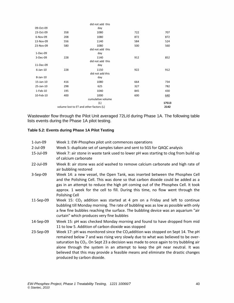
EW-Phosphex Project, Phase 1 Treatability Testing, 1221 10066/7 © Stantec, 2010
40
09-Oct-09
did not add this day
23-Oct-09 358
1080
722
707
6-Nov-09 208
1080
872
872
13-Nov-09 556
1140
584
524
23-Nov-09 580
1080
500
560
1-Dec-09
did not add this day
3-Dec-09 228
1140
912
852
11-Dec-09
did not add this day
6-Jan-10 228
1150
922
912
8-Jan-10
did not add this day
15-Jan-10 416
1080
664
734
25-Jan-10 298
625
327
782
1-Feb-10 195
1040
845
430
10-Feb-10 400
1000
600
640
cumulative volume (L)
17513
volume lost to ET and other factors (L)
2142
Wastewater flow through the Pilot Unit averaged 72L/d during Phase 1A. The following table lists events during the Phase 1A pilot testing. Table 5.2: Events during Phase 1A Pilot Testing
1-Jun-09 Week 1: EW-Phosphex pilot unit commences operations
2-Jul-09 Week 5: duplicate set of samples taken and sent to SGS for QAQC analysis
15-Jul-09 Week 7: air stone in waste tank used to lower pH was starting to clog from build up of calcium carbonate
22-Jul-09 Week 8: air stone was acid washed to remove calcium carbonate and high rate of air bubbling restored
3-Sep-09 Week 14: a new vessel, the Open Tank, was inserted between the Phosphex Cell and the Polishing Cell. This was done so that carbon dioxide could be added as a gas in an attempt to reduce the high pH coming out of the Phosphex Cell. It took approx. 1 week for the cell to fill. During this time, no flow went through the Polishing Cell
11-Sep-09 Week 15: CO2 addition was started at 4 pm on a Friday and left to continue bubbling till Monday morning. The rate of bubbling was as low as possible with only a few fine bubbles reaching the surface. The bubbling device was an aquarium "air curtain" which produces very fine bubbles
14-Sep-09 Week 15: pH was checked Monday morning and found to have dropped from mid 11 to low 5. Addition of carbon dioxide was stopped
23-Sep-09 Week 17: pH was monitored since the CO2addition was stopped on Sept 14. The pH remained below 7 and was rising very slowly due to what was believed to be over-saturation by CO2. On Sept 23 a decision was made to once again to try bubbling air alone through the system in an attempt to keep the pH near neutral. It was believed that this may provide a feasible means and eliminate the drastic changes produced by carbon dioxide.
EW-Phosphex Project, Phase 1 Treatability Testing, 1221 10066/7 © Stantec, 2010
41
9-Oct-09 Week 19: air bubbling in the Open Tank continued until this date. At this point it was found that air alone was not sufficient to reduce the pH. It appears that when air is added to a flow through system there is, over time, a build up of calcium carbonate which effectively neutralized the affect of any carbonic acid formed from the bubbling of air. Over time the pH rose back in to the 11s
9-Oct-09 Week 19: CO2 addition was again resumed in the afternoon of this date. The addition of CO2 was timed for only an hour or two and not allowed to run continuously. This was done to determine if the pH could be reduced in a more controlled manner.
30-Oct-09 Week 22: resumed collection of full set of sample parameters for Phase 1A EW-Phosphex System
1-Nov-09 Week 23: pH of CO2 cell adjusted with the addition of 100% CO2 gas. The addition was done at 1 to two day interval but not adjusted on weekends. This practice will continue until notified otherwise
16-Dec-09 Week 30: flow through the system was stopped for Christmas shut down
5-Jan-10 Week 33: dead cattail vegetation removed
6-Jan-10 Week 33: indoor holding tank was filled with sewage in preparation of restarting the flow through the system
7-Jan-10 Week 33: flow restarted through system and pH adjusted with 100% CO2
8-Feb-10 Week 37: last intensive sampling period. System is currently being fed sewage and will continue to flow until no longer needed.
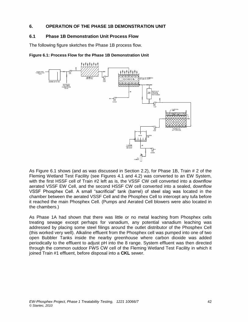
EW-Phosphex Project, Phase 1 Treatability Testing, 1221 10066/7 © Stantec, 2010
42
6. OPERATION OF THE PHASE 1B DEMONSTRATION UNIT
6.1 Phase 1B Demonstration Unit Process Flow
The following figure sketches the Phase 1B process flow. Figure 6.1: Process Flow for the Phase 1B Demonstration Unit
As Figure 6.1 shows (and as was discussed in Section 2.2), for Phase 1B, Train # 2 of the Fleming Wetland Test Facility (see Figures 4.1 and 4.2) was converted to an EW System, with the first HSSF cell of Train #2 left as is, the VSSF CW cell converted into a downflow aerated VSSF EW Cell, and the second HSSF CW cell converted into a sealed, downflow VSSF Phosphex Cell. A small “sacrificial” tank (barrel) of steel slag was located in the chamber between the aerated VSSF Cell and the Phosphex Cell to intercept any tufa before it reached the main Phosphex Cell. (Pumps and Aerated Cell blowers were also located in the chambers.) As Phase 1A had shown that there was little or no metal leaching from Phosphex cells treating sewage except perhaps for vanadium, any potential vanadium leaching was addressed by placing some steel filings around the outlet distributor of the Phosphex Cell (this worked very well). Alkaline effluent from the Phosphex cell was pumped into one of two open Bubbler Tanks inside the nearby greenhouse where carbon dioxide was added periodically to the effluent to adjust pH into the 8 range. System effluent was then directed through the common outdoor FWS CW cell of the Fleming Wetland Test Facility in which it joined Train #1 effluent, before disposal into a CKL sewer.
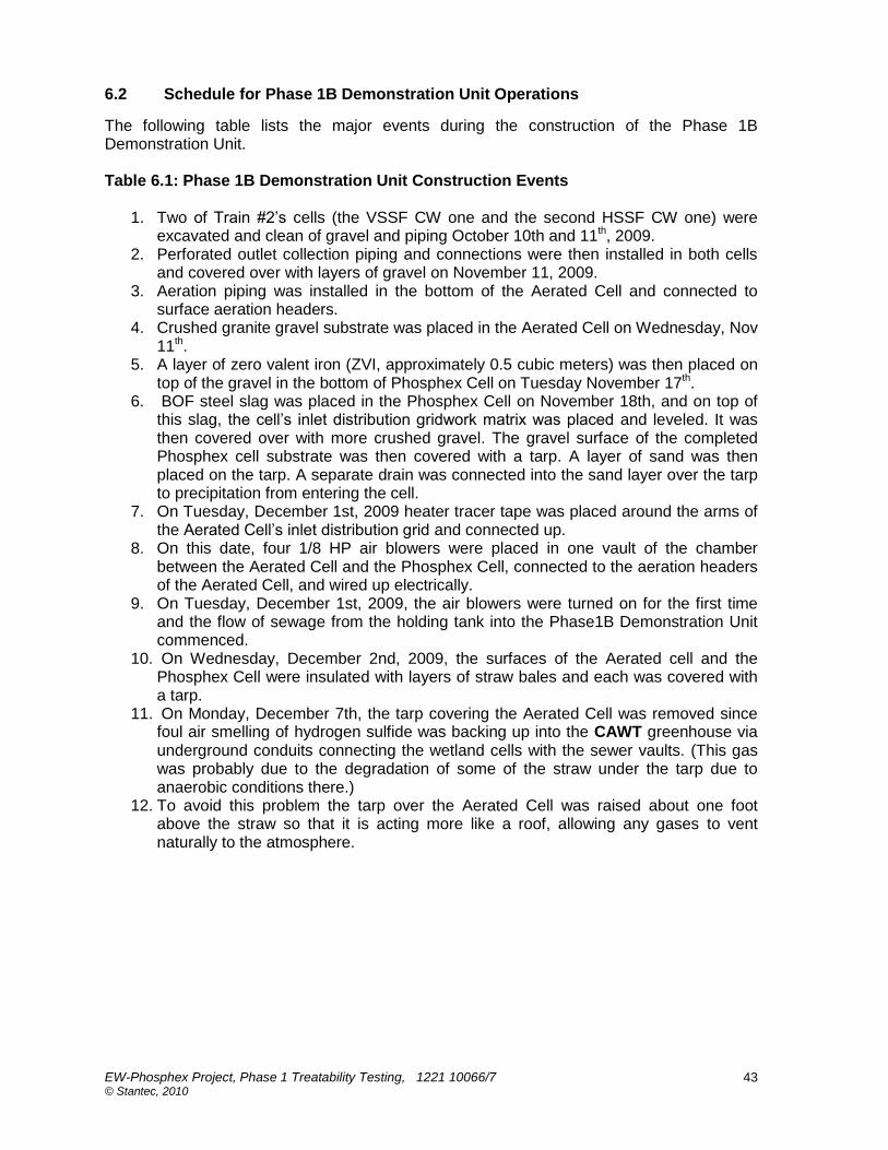
EW-Phosphex Project, Phase 1 Treatability Testing, 1221 10066/7 © Stantec, 2010
43
6.2 Schedule for Phase 1B Demonstration Unit Operations
The following table lists the major events during the construction of the Phase 1B Demonstration Unit. Table 6.1: Phase 1B Demonstration Unit Construction Events
1. Two of Train #2‟s cells (the VSSF CW one and the second HSSF CW one) were excavated and clean of gravel and piping October 10th and 11th, 2009.
2. Perforated outlet collection piping and connections were then installed in both cells and covered over with layers of gravel on November 11, 2009.
3. Aeration piping was installed in the bottom of the Aerated Cell and connected to surface aeration headers.
4. Crushed granite gravel substrate was placed in the Aerated Cell on Wednesday, Nov 11th.
5. A layer of zero valent iron (ZVI, approximately 0.5 cubic meters) was then placed on top of the gravel in the bottom of Phosphex Cell on Tuesday November 17th.
6. BOF steel slag was placed in the Phosphex Cell on November 18th, and on top of this slag, the cell‟s inlet distribution gridwork matrix was placed and leveled. It was then covered over with more crushed gravel. The gravel surface of the completed Phosphex cell substrate was then covered with a tarp. A layer of sand was then placed on the tarp. A separate drain was connected into the sand layer over the tarp to precipitation from entering the cell.
7. On Tuesday, December 1st, 2009 heater tracer tape was placed around the arms of the Aerated Cell‟s inlet distribution grid and connected up.
8. On this date, four 1/8 HP air blowers were placed in one vault of the chamber between the Aerated Cell and the Phosphex Cell, connected to the aeration headers of the Aerated Cell, and wired up electrically.
9. On Tuesday, December 1st, 2009, the air blowers were turned on for the first time and the flow of sewage from the holding tank into the Phase1B Demonstration Unit commenced.
10. On Wednesday, December 2nd, 2009, the surfaces of the Aerated cell and the Phosphex Cell were insulated with layers of straw bales and each was covered with a tarp.
11. On Monday, December 7th, the tarp covering the Aerated Cell was removed since foul air smelling of hydrogen sulfide was backing up into the CAWT greenhouse via underground conduits connecting the wetland cells with the sewer vaults. (This gas was probably due to the degradation of some of the straw under the tarp due to anaerobic conditions there.)
12. To avoid this problem the tarp over the Aerated Cell was raised about one foot above the straw so that it is acting more like a roof, allowing any gases to vent naturally to the atmosphere.

EW-Phosphex Project, Phase 1 Treatability Testing, 1221 10066/7 © Stantec, 2010
44
6.3 Phase 1B Demonstration Unit Operations
The following list summarizes events occurring during the operation of the Phase 1B Demonstration Unit over the period from late December of 2009 until late July of 2010.
1. On Monday, December 7th, treated effluent started flowing out of the Phosphex Cell for the first time.
2. On Wednesday, December 10th, 2009 the pH of the treated effluent from the Phosphex Cell was first measured and found to be near 12, even when air was vigorously bubbled through it. Accordingly, the flow of sewage has been stopped since the pH of the effluent prior to pumping to sanitary sewer was above the College‟s discharge limit of 10.5.
3. A Waterloo Emitter was ordered to help reduce the pH. This emitter was composed of silicon tubing through which carbon dioxide diffuses (across a concentration gradient). The emitter was tried at a variety of locations within the system under different conditions (outside, inside, cold, warm) throughout the remainder of December and into January 2010. The Waterloo Emitter was only minimally successful and pH remained in the high 11s.
4. On January 10, 2010 a plastic tote (Bubbler Tank) was installed inside the CAWT greenhouse and high pH effluent from the Demonstration Unit‟s Phosphex Cell was directed to it for treatment with CO2 diffused through the Waterloo Emitter.
5. By January 21, 2010, it was clear that the diffusion of CO2 through the Waterloo Emitter was not sufficiently large enough in volume to lower the pH of the Phosphex Cell‟s alkaline effluent. The residency time was just too short. (The residence time in the Bubbler Tank was estimated at only a few hours.)
6. By January 30, 2010, the high pH of Phosphex Cell effluent continued to be an issue flow through the Demonstration Unit was turned on only during the short periods of time necessary to collect samples for analysis. A record of exact flow volumes was not kept since flows were kept to a minimum and the unit did not operate every day while resolution of the high pH issue was being sought. In addition there was a concern that feed flow meter might have been starting to clog.
7. On February 10, the submersible pump moving effluent from Phosphex Cell to the CKL sanitary sewer became plugged with what appeared to be calcium carbonate. The pump‟s impellers were cleaned.
8. On February 17, the flow meter located in the outdoor chamber downstream of the Phosphex Cell and measuring the volume of flow from Demonstration Unit became clogged with what appeared to be tufa (calcium carbonate). A decision was made to relocate the flow meter to inside the CAWT greenhouse just upstream of the Bubbler Tank.
9. On March 26, 2010, a second Bubbler Tank (1000L tote) was plumbed in series with the one already in the CAWT greenhouse. This gave a combined volume of 2000L of capacity in which treat for pH control. At the same time, “air curtain” CO2 diffusers were installed in each tank. The new arrangement showed promise by effectively dropping effluent pH to between 7 and 9 from a combination of increased residency time and a greater volume in which to diffuse CO2 into the effluent. (The “air curtains” were finely perforated silicon tubes used to produce fine scale bubbles in aquarium tanks.)
10. On April 15, 2010, the straw which had been used as insulation was removed from the surfaces of Aerated Cell and the Phosphex Cell.
11. On May 2, the submersible pump transferring high pH effluent from Phosphex Cell to CO2 Bubbler Tanks failed.
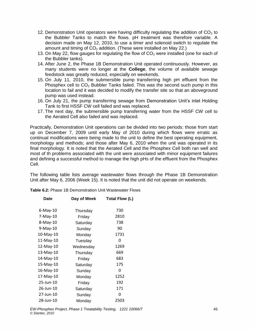
EW-Phosphex Project, Phase 1 Treatability Testing, 1221 10066/7 © Stantec, 2010
45
12. Demonstration Unit operators were having difficulty regulating the addition of CO2 to
the Bubbler Tanks to match the flows. pH treatment was therefore variable. A decision made on May 12, 2010, to use a timer and solenoid switch to regulate the amount and timing of CO2 addition. (These were installed on May 22.)
13. On May 22, flow gauges for regulating the flow of CO2 were installed (one for each of the Bubbler tanks).
14. After June 2, the Phase 1B Demonstration Unit operated continuously. However, as many students were no longer at the College, the volume of available sewage feedstock was greatly reduced, especially on weekends.
15. On July 11, 2010, the submersible pump transferring high pH effluent from the Phosphex cell to CO2 Bubbler Tanks failed. This was the second such pump in this location to fail and it was decided to modify the transfer site so that an aboveground pump was used instead.
16. On July 21, the pump transferring sewage from Demonstration Unit‟s inlet Holding Tank to first HSSF CW cell failed and was replaced.
17. The next day, the submersible pump transferring water from the HSSF CW cell to the Aerated Cell also failed and was replaced.
Practically, Demonstration Unit operations can be divided into two periods: those from start up on December 7, 2009 until early May of 2010 during which flows were erratic as continual modifications were being made to the unit to define the best operating equipment, morphology and methods; and those after May 6, 2010 when the unit was operated in its final morphology. It is noted that the Aerated Cell and the Phosphex Cell both ran well and most of th problems associated with the unit were associated with minor equipment failures and defining a successful method to manage the high pHs of the effluent from the Phosphex Cell. The following table lists average wastewater flows through the Phase 1B Demonstration Unit after May 6, 2006 (Week 15). It is noted that the unit did not operate on weekends. Table 6.2: Phase 1B Demonstration Unit Wastewater Flows
Date Day of Week Total Flow (L)
6-May-10 Thursday 730
7-May-10 Friday 2810
8-May-10 Saturday 738
9-May-10 Sunday 90
10-May-10 Monday 1731
11-May-10 Tuesday 0
12-May-10 Wednesday 1269
13-May-10 Thursday 669
14-May-10 Friday 683
15-May-10 Saturday 175
16-May-10 Sunday 0
17-May-10 Monday 1252
25-Jun-10 Friday 192
26-Jun-10 Saturday 171
27-Jun-10 Sunday 0
28-Jun-10 Monday 2503

EW-Phosphex Project, Phase 1 Treatability Testing, 1221 10066/7 © Stantec, 2010
46
29-Jun-10 Tuesday 1189
5-Jul-10 Monday 443
6-Jul-10 Tuesday 2874
7-Jul-10 Wednesday 1277
8-Jul-10 Thursday 1515
9-Jul-10 Friday 1906
10-Jul-10 Saturday 84
11-Jul-10 Sunday 0
12-Jul-10 Monday 1627
13-Jul-10 Tuesday 167
14-Jul-10 Wednesday 604
15-Jul-10 Thursday 1044
16-Jul-10 Friday 1718
17-Jul-10 Saturday 435
18-Jul-10 Sunday 0
19-Jul-10 Monday 1971
20-Jul-10 Tuesday 267
21-Jul-10 Wednesday 1695
22-Jul-10 Thursday 921
23-Jul-10 Friday 1491
24-Jul-10 Saturday 0
25-Jul-10 Sunday 1348
26-Jul-10 Monday 569 The average flow rate through the Demonstration Unit up to the end of July, not including weekends and the July 1, 2010 holiday period, was 927 L/d.

EW-Phosphex Project, Phase 1 Treatability Testing, 1221 10066/7 © Stantec, 2010
47
7. ANALYTICAL TESTING & METHODOLOGY
7.1 Phase 1 Monitoring
Analytical results are found in Appendix A (Phase 1A) and Appendix B (Phase 1B) of accompanying Volume 2. Most of the analytical tests were carried out by CAWT staff, with a number of back up analyses carried out by UoW (shaded data in the tables).QA/QC tests were performed by SGS. The main streams sampled during Phase 1A were the system influent (Mixing Tank outlet water), Aerated Cell outlet water, Phosphex cell outlet water, and (in some cases) water in the Open Tank. Both CAWT and UofW analytical results for Phase 1A are listed in Appendix A of this Report and are listed by week from the first week after end of the four-week Acclimatization Period as Weeks 1 – 38. Where analytical results were reported as below the minimum detection limit (<MDL), averages involving such readings were computed assuming the value was half the lowest MDL available (Clark, 1998). During Phase 1A, samples were collected weekly at the sampling ports by the outlet of the Pilot Unit Mixing Tank (system influent), the outlet of Aerated Cell, the outlet of the Phosphex Cell, in the Open Tank and/or the outlet of the Polishing Cell (system effluent). It is noted that analyses of the influent sewage in the feed tank were also taken periodically but are not reported as these compositions could and did change during the sewage‟s residence time in that vessel. Additionally, it is emphasized that the results of analyses of system effluent from final Polishing Cell are of interest only, as this vessel as built was better approximated as an “Anaerobic” CW cell than the FWS CW cell originally intended. The main streams of interest during Phase 1B were the system influent (HSSF Cell outlet water), Aerated Cell outlet water, Phosphex Cell outlet water, and (in some cases) water in the Open Tank. Both CAWT and UofW analytical results for Phase 1B are listed in Appendix B of this Report and are listed by week from the first week after end of the four-week Acclimatization Period as Weeks 1 – 38. Where analytical results were reported as below the minimum detection limit (<MDL), averages involving such readings also were computed assuming the value was half the lowest MDL available (Clark, 1998). During Phase 1B, samples were collected weekly at the sampling ports by the outlet of the Pilot Unit Holding Tank (system influent), the outlet of HSSF Cell, the outlet of Aerated Cell, the outlet of the Phosphex Cell, and in and out of the Bubbler Tanks (system effluent).
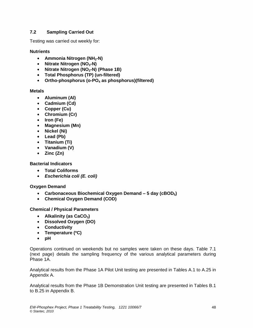
EW-Phosphex Project, Phase 1 Treatability Testing, 1221 10066/7 © Stantec, 2010
48
7.2 Sampling Carried Out
Testing was carried out weekly for: Nutrients
Ammonia Nitrogen (NH3-N)
Nitrate Nitrogen (NO3-N)
Nitrate Nitrogen (NO2-N) (Phase 1B)
Total Phosphorus (TP) (un-filtered)
Ortho-phosphorus (o-PO4 as phosphorus)(filtered) Metals
Aluminum (Al)
Cadmium (Cd)
Copper (Cu)
Chromium (Cr)
Iron (Fe)
Magnesium (Mn)
Nickel (Ni)
Lead (Pb)
Titanium (Ti)
Vanadium (V)
Zinc (Zn) Bacterial Indicators
Total Coliforms
Escherichia coli (E. coli) Oxygen Demand
Carbonaceous Biochemical Oxygen Demand – 5 day (cBOD5)
Chemical Oxygen Demand (COD) Chemical / Physical Parameters
Alkalinity (as CaCO3)
Dissolved Oxygen (DO)
Conductivity
Temperature (ºC)
pH Operations continued on weekends but no samples were taken on these days. Table 7.1 (next page) details the sampling frequency of the various analytical parameters during Phase 1A. Analytical results from the Phase 1A Pilot Unit testing are presented in Tables A.1 to A.25 in Appendix A. Analytical results from the Phase 1B Demonstration Unit testing are presented in Tables B.1 to B.25 in Appendix B.
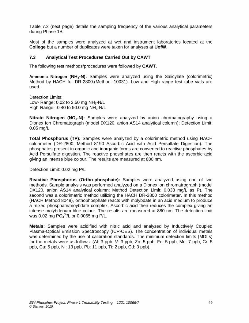
EW-Phosphex Project, Phase 1 Treatability Testing, 1221 10066/7 © Stantec, 2010
49
Table 7.2 (next page) details the sampling frequency of the various analytical parameters during Phase 1B. Most of the samples were analyzed at wet and instrument laboratories located at the College but a number of duplicates were taken for analyses at UofW. 7.3 Analytical Test Procedures Carried Out by CAWT
The following test methods/procedures were followed by CAWT. Ammonia Nitrogen (NH3-N): Samples were analyzed using the Salicylate (colorimetric) Method by HACH for DR-2800.(Method: 10031). Low and High range test tube vials are used. Detection Limits: Low- Range: 0.02 to 2.50 mg NH3-N/L High-Range: 0.40 to 50.0 mg NH3-N/L Nitrate Nitrogen (NO3-N): Samples were analyzed by anion chromatography using a Dionex Ion Chromatograph (model DX120, anion AS14 analytical column); Detection Limit: 0.05 mg/L Total Phosphorus (TP): Samples were analyzed by a colorimetric method using HACH colorimeter (DR-2800: Method 8190 Ascorbic Acid with Acid Persulfate Digestion). The phosphates present in organic and inorganic forms are converted to reactive phosphates by Acid Persulfate digestion. The reactive phosphates are then reacts with the ascorbic acid giving an intense blue colour. The results are measured at 880 nm. Detection Limit: 0.02 mg P/L Reactive Phosphorus (Ortho-phosphate): Samples were analyzed using one of two methods. Sample analysis was performed analyzed on a Dionex ion chromatrograph (model DX120, anion AS14 analytical column; Method Detection Limit: 0.033 mg/L as P). The second was a colorimetric method utilizing the HACH DR-2800 colorimeter. In this method (HACH Method 8048), orthophosphate reacts with molybdate in an acid medium to produce a mixed phosphate/moybdate complex. Ascorbic acid then reduces the complex giving an intense molybdenum blue colour. The results are measured at 880 nm. The detection limit was 0.02 mg PO4
3-/L or 0.0065 mg P/L. Metals: Samples were acidified with nitric acid and analyzed by Inductively Coupled Plasma-Optical Emission Spectroscopy (ICP-OES). The concentration of individual metals was determined by the use of calibration standards. The minimum detection limits (MDLs) for the metals were as follows: (Al: 3 ppb, V: 3 ppb, Zn: 5 ppb, Fe: 5 ppb, Mn: 7 ppb, Cr: 5 ppb, Cu: 5 ppb, Ni: 13 ppb, Pb: 11 ppb, Ti: 2 ppb, Cd: 3 ppb).
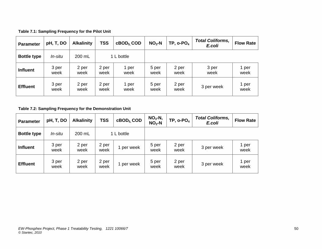
EW-Phosphex Project, Phase 1 Treatability Testing, 1221 10066/7 © Stantec, 2010
50
Table 7.1: Sampling Frequency for the Pilot Unit
Parameter pH, T, DO Alkalinity TSS cBOD5, COD NO3-N TP, o-PO4
Total Coliforms, E.coli
Flow Rate
Bottle type In-situ 200 mL 1 L bottle
Influent 3 per week
2 per week
2 per week
1 per week
5 per week
2 per week
3 per week
1 per week
Effluent 3 per week
2 per week
2 per week
1 per week
5 per week
2 per week
3 per week 1 per week
Table 7.2: Sampling Frequency for the Demonstration Unit
Parameter pH, T, DO Alkalinity TSS cBOD5, COD
NO3-N, NO2-N
TP, o-PO4 Total Coliforms,
E.coli Flow Rate
Bottle type In-situ 200 mL 1 L bottle
Influent 3 per week
2 per week
2 per week
1 per week 5 per week
2 per week
3 per week 1 per week
Effluent 3 per week
2 per week
2 per week
1 per week 5 per week
2 per week
3 per week 1 per week

EW-Phosphex Project, Phase 1 Treatability Testing, 1221 10066/7 © Stantec, 2010
51
Total Coliform and E.coli: Samples were analyzed for these microbial indicator groups using a 96 well titer plate method more commonly referred to as Coliplates. This method provides a quantitative measure of total coliforms and E.coli. It contains selective media that cause a colorimetric reaction with proteins specific to these two indicator groups. The test plates are incubated for 24 h@ 35°C and the appearance of a blue/green colour is indicative of the presence of total coliforms. E.coli are detected by fluorescence under a long wavelength UV light. The number of wells within the 96 well plate provides a quantitative measure of microbial density. Quantification is based on Most Probable Number of Colony Forming Units (cfu) per 100 mL of sample. Detection Ranges: 3 to 2,400 cfu/100 mL in a single test plate without dilution. Samples with higher cfu counts are analyzed by diluting the sample to within a concentration measurable on the 96 well plate. Carbonaceous Biochemical Oxygen Demand- 5 day (cBOD5): Samples were analyzed using the BOD Method outlined in APHA 1998(SM 5210 B). The method consists of filling 500ml bottles with sample to overflowing, air-tight sealing of the bottles and incubating them at 20 degrees Celsius for a 5 day period. The BOD represents the consumption of oxygen within the sample over this 5 day period as determined by assessing the difference in oxygen concentration from the initial DO concentration and the final DO concentration. Dilutions are performed for quality control purpose along with the use of glucose-glutamic acid as a standard to determine accuracy. Meter range: The working range is equal to the difference between the maximum initial DO (7 to 9 mg/L ) and minimum DO residual of 1 mg/L multiplied by the dilution factor. Chemical Oxygen Demand (COD): Samples were analyzed using the HACH Reactor Method designed for DR-2800.(Method-8000). In brief, the sample is heated for two hours with potassium dichromate (a strong oxidizing agent). Oxidizable organic compounds react, reducing the dichromate ion to a green chromic ion which is measured with a HACH colorimeter. Two different procedures were used depending on predicted oxygen consumption rates. When a high rate of oxygen consumption was anticipated (e.g., 3 to 150 mg/L – low range) the colorimetric determination is based on the generation of Cr6+ (measured at 420 nm). When oxygen consumption rates are anticipated to be high (e.g., 20 to 1500 mg/L) the determination was based on the generation of Cr3+ (measured at 620 nm). Meter ranges: Low range: 3 - 150 mg/L High Range: 20 - 1500 mg/L Alkalinity: Samples were analyzed by utilizing a potentiometric titration. This involves titrating a known volume of sample with sulphuric acid at a specific concentration of 0.2N. An Accumet pH meter was used to monitor pH during the titration. The equivalence point was set at a pH of 4.5. The volume of the 0.2N sulphuric acid added at the equivalence point of the titration was then used to calculate the alkalinity of the water, which is reported as mg CaCO3/L. Detection Limit: Samples containing less than 20 mg/L were tested using higher sample volumes (100 mL or more). Also, the strength of the acid can be reduced if obtaining a higher volume is not possible. In practice, the minimum detection limit for this project was 10 mg CaCO3/L.

EW-Phosphex Project, Phase 1 Treatability Testing, 1221 10066/7 © Stantec, 2010
52
Dissolved Oxygen: Samples were analyzed using a YSI 5100 Dissolved Oxygen Meter following the method outlined in YSI Model 5100 Operations Manual. Meter range: 0.0 to 60.00 mg/L Conductivity: Samples were analyzed using a YSI 3100 Conductivity meter (equipped with a temperature sensor and a Platinum electrode) based on the method outlined in APHA 1998 (SM 2510 B). Meter range: 0 – 4999 uS/cm Temperature: Samples were analyzed in conjunction with the DO analysis using a YSI 5100 Dissolved Oxygen Meter following the method outlined in YSI Model 5100 Operations Manual. pH: Samples were analyzed with an Accumet AR25 pH meter using the electrometric method outlined in APHA 1998 (SM 4500 H+ B). The electromotive force produced in the glass electrode system varies linearly with pH and this is described by plotting the measured EMF against the pH of buffer 4, 7 and 10. Sample pH is determined by extrapolation. Meter range: - 2 to +20 7.4 Analytical Test Procedures Carried Out by UoW
In addition to the samples taken and analyzed by CAWT staff, periodic duplicate samples were taken by a University of Waterloo graduate student, and taken to the university for analyses for TP, o-PO4 and metals using the very sophisticated test equipment available there, capable of giving results to much lower MDLs. Thermo Orion™ electrodes were used for measuring the pH of each cell effluent immediately after collection. In order to bracket the range of pH conditions of the cells being tested, the pH electrodes were calibrated daily using pH 7 and 10 buffers. At UoW, alkalinity was measured using a Hach™ digital titrator and standardized sulfuric acid and with phenolphthalein and bromocresol green-methyl red pH indicator on filtered samples (using 0.45μm filter). At UoW, ortho-phosphate samples were filtered through 0.45 μm filter and preserved with trace-metal grade H2SO4 to pH <2. These samples were analyzed by Hach DR-2800 colorimeter using ascorbic acid method within 7 days of collection. Using the ascorbic acid method, orthophosphate reacts with ammonium molybdate and potassium antimony tartrate reacts in acid medium to form phosphomolybdic acid, a heteropoly acid. This phosphomolybdic acid was reduced to intensely colored molybdenum blue by ascorbic acid. The method detection limit calculated by using the following expression: MDL = Student's t x ,where the Student‟s t value (listed in the operation manual of the instrument) and standard deviation (s) of sub samples (at least 7) of the standard concentration, which is 1 to 5 times of the estimated Hach detection limit. MDL=0.003 mg o-PO4-P /L Cation/metals samples were filtered using 0.45μm filter and preserved with trace-metal grade concentrated nitric acid to pH<2. All samples were stored refrigerated until analyzed at the UoW Analytical laboratory. The major cations, metals and metalloids, including the

EW-Phosphex Project, Phase 1 Treatability Testing, 1221 10066/7 © Stantec, 2010
53
following metals measured by ICP MS: Al, V, Zn, Fe, Mn, Cr, Cu, Ni, Pb, Ti, and Cd were analyzed by inductively coupled plasma optical emission spectroscopy (ICP-OES) and/or inductively coupled plasma mass spectrometry (ICP-MS). The method detection limit of the ICP_OES was automatically calculated by the instrument and the method detection limit of the ICP_MS was calculated for each analysis following the standard method using the standard deviation of the ICP-MS signal of the blank. Thus, the detection limits for these two methods may be different from one analysis to another.

EW-Phosphex Project, Phase 1 Treatability Testing, 1221 10066/7 © Stantec, 2010
54
8. DISCUSSION OF RESULTS FOR PHASE 1A PILOT TESTING
8.1 General
The results for for the Phase 1A Pilot Unit part of the Phase 1 Treatability Testing are presented in Appendices A-1 to A-25 of accompanying Volume 2, and are discussed in the following sections. Unless stated otherwise, where averages are presented in the tables of Appendix A, they are for the period from Week 16 of the pilot testing (after the middle of September, 2009, when the Open Tank was moved to a location after the Phosphex Cell instead of after the Polishing Cell) up until the end of the testing (from Weeks 36 to 39, depending on the parameter involved) in February of 2010. Where particular values of a parameter in the tables of Appendix A are listed as being below minimum detection limits (<MDL), averages are taken by assuming that that value is given by half of the MDL (Clark, 1988). It is also noted that for some parameters (e.g., phosphorus, some metals) duplicate samples were analyzed both at CAWT (for which MDLs are higher using standard analytical methods) and at the university (where much lower detection limits were possible). The averages at the bottom of some of the tables of Appendix A lump all of these values together and for some parameters may be misleadingly high, as are discussed below. 8.2 Total Phosphorus Removal during Phase 1A
Table A-1 in Appendix A presents the results for Total Phosphorus (TP) removal during Phase 1A expressed in mg/L (ppm) while Table A-2 presents the same results expressed in micrograms per litre (μg o-PO4/L or ppb) as a comparison and a way of seeing more exact levels of phosphorus in Phosphex cell outlet water. As can be seen from Table A-1, for Weeks 16 – 38 the influent total phosphorus concentrations (un-filtered) ranged from just over 3 mg/L to almost 12 mg/L, averaging about 7 mg/L. Total phosphorus concentrations out of the Aerated Cell ranged from just under 2 mg/L to just over 8 mg/L, averaging 5 mg/L and indicating an average removal of 24%. There are various possible reasons for the removal of one quarter of the influent phosphorus in the Aerated Cell: adsorption on still unsaturated sorption sites on the cell‟s limestone substrate (not likely as the cell had operated for some time); biotic or abiotic interactions with the traces of iron in the feed; and/or the formation of hydroxyl apatite [Ca5(OH)2(PO4)3] (Reddy & D‟Angelo, 1994). It is probable that such Aerated Cell phosphorus removal would not be sustainable long term in a commercial-scale EW System (Kadelec & Wallace, 2008). As may be seen from Table A-2, the concentrations of total phosphorus in the outlet from the Phosphex Cell ranged after Week 16 from non-detect (e.g., below the MDLs, some of which were as low as 3.3 μ/L) to 57 μg TP/L, and averaged 39 μg TP/L (0.04 mg TP/L), a removal of 99.2%. (If only the UoW results involving lower MDLs are considered, the average Phosphex Cell effluent total phosphorus concentration is 13 μg TP/L! Concentrations of phosphate were measured at UofW as low as 0.005 with UV-Spectrophotometer using ascorbic acid method.) The treatment performance of the Phosphex Cell stayed much the same regardless of variations in the influent total phosphorus concentration. The phosphorus loading into the Phosphex Cell increased from week 24, but the treatment performance in terms of percent removal did not decrease; in fact it was even better. The changes in flow rate did not affect the treatment performance as the maximum flow rate of the system (184 L/d) was much lower than the pore volume (~345 L). Thus, the residence time is always more than 1 day, as recommended.
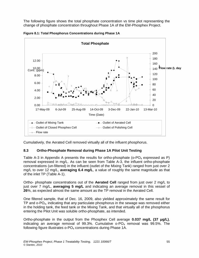
EW-Phosphex Project, Phase 1 Treatability Testing, 1221 10066/7 © Stantec, 2010
55
The following figure shows the total phosphate concentration vs time plot representing the change of phosphate concentration throughout Phase 1A of the EW-Phosphex Project. Figure 8.1: Total Phosphorus Concentrations during Phase 1A
Cumulatively, the Aerated Cell removed virtually all of the influent phosphorus. 8.3 Ortho-Phosphate Removal during Phase 1A Pilot Unit Testing
Table A-3 in Appendix A presents the results for ortho-phosphate (o-PO4 expressed as P) removal expressed in mg/L. As can be seen from Table A-3, the influent ortho-phosphate concentrations (un-filtered) in the influent (outlet of the Mixing Tank) ranged from just over 2 mg/L to over 12 mg/L, averaging 6.4 mg/L, a value of roughly the same magnitude as that of the inlet TP (Table A-1). Ortho- phosphate concentrations out of the Aerated Cell ranged from just over 2 mg/L to just over 7 mg/L, averaging 5 mg/L and indicating an average removal in this vessel of 26%, as expected almost the same amount as the TP removal in the Aerated Cell. One filtered sample, that of Dec. 16, 2009, also yielded approximately the same result for TP and o-PO4, indicating that any particulate phosphorus in the sewage was removed either in the holding tank, the feed tank or the Mixing Tank, and that virtually all of the phosphorus entering the Pilot Unit was soluble ortho-phosphate, as intended. Ortho-phosphate in the output from the Phosphex Cell average 0.037 mg/L (37 μg/L), indicating an average removal of 99.3%. Cumulative o-PO4 removal was 99.5%. The following figure illustrates o-PO4 concentrations during Phase 1A.
Total Phosphate
0.00
2.00
4.00
6.00
8.00
10.00
12.00
17-May-09 6-Jul-09 25-Aug-09 14-Oct-09 3-Dec-09 22-Jan-10 13-Mar-10
Time (Date)
Conc. (ppm)
0
20
40
60
80
100
120
140
160
180
200
Flow rate (L day -1 )
Outlet of Mixing Tank Outlet of Aerated Cell
Outlet of Closed Phosphex Cell Outlet of Polishing Cell
Flow rate
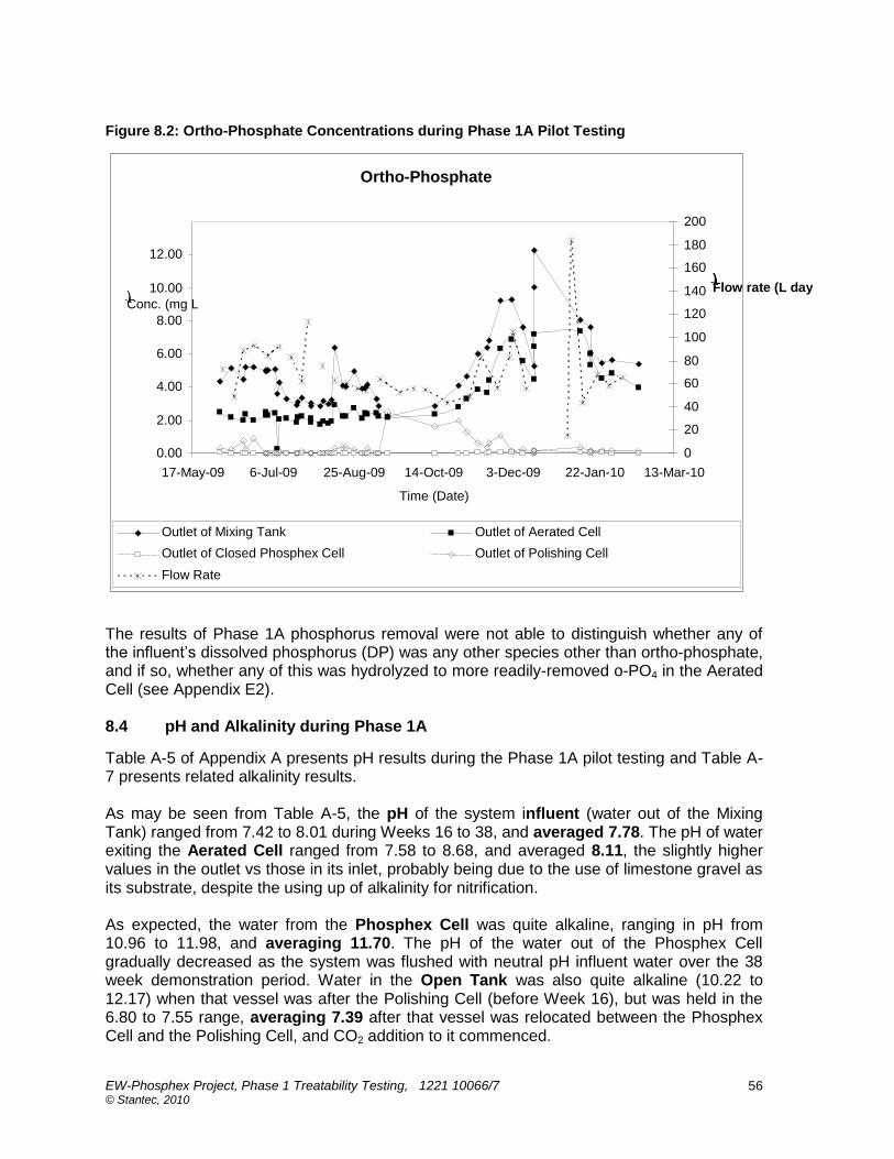
EW-Phosphex Project, Phase 1 Treatability Testing, 1221 10066/7 © Stantec, 2010
56
Figure 8.2: Ortho-Phosphate Concentrations during Phase 1A Pilot Testing
The results of Phase 1A phosphorus removal were not able to distinguish whether any of the influent‟s dissolved phosphorus (DP) was any other species other than ortho-phosphate, and if so, whether any of this was hydrolyzed to more readily-removed o-PO4 in the Aerated Cell (see Appendix E2). 8.4 pH and Alkalinity during Phase 1A
Table A-5 of Appendix A presents pH results during the Phase 1A pilot testing and Table A-7 presents related alkalinity results. As may be seen from Table A-5, the pH of the system influent (water out of the Mixing Tank) ranged from 7.42 to 8.01 during Weeks 16 to 38, and averaged 7.78. The pH of water exiting the Aerated Cell ranged from 7.58 to 8.68, and averaged 8.11, the slightly higher values in the outlet vs those in its inlet, probably being due to the use of limestone gravel as its substrate, despite the using up of alkalinity for nitrification. As expected, the water from the Phosphex Cell was quite alkaline, ranging in pH from 10.96 to 11.98, and averaging 11.70. The pH of the water out of the Phosphex Cell gradually decreased as the system was flushed with neutral pH influent water over the 38 week demonstration period. Water in the Open Tank was also quite alkaline (10.22 to 12.17) when that vessel was after the Polishing Cell (before Week 16), but was held in the 6.80 to 7.55 range, averaging 7.39 after that vessel was relocated between the Phosphex Cell and the Polishing Cell, and CO2 addition to it commenced.
Ortho-Phosphate
0.00
2.00
4.00
6.00
8.00
10.00
12.00
17-May-09 6-Jul-09 25-Aug-09 14-Oct-09 3-Dec-09 22-Jan-10 13-Mar-10
Time (Date)
Conc. (mg L -1 )
0
20
40
60
80
100
120
140
160
180
200
Flow rate (L day -1 )
Outlet of Mixing Tank Outlet of Aerated Cell
Outlet of Closed Phosphex Cell Outlet of Polishing Cell
Flow Rate

EW-Phosphex Project, Phase 1 Treatability Testing, 1221 10066/7 © Stantec, 2010
57
Elevated Phosphex Cell outlet water pH was identified as one of the concerns for an EW-Phosphex treatment system. However, the high pHs can be successfully managed by diffusing CO2 after the Phosphex Cell. Once CO2 was added to Phosphex Cell outlet water, its pH was able to be maintained within PWQO guidelines (pHs of 6.5 - 8.5). The precipitation of calcium carbonate in Phosphex cell outlet water can be managed by maintaining this stream near neutral pH, as the formation of highly soluble bicarbonate species (HCO3
-) dominates between pH 6.3 and 10.3. The following figure illustrates pHs during the Phase 1A pilot testing. Figure 8.3: pHs during Phase 1A Pilot Testing
In summary, the pH of water out of the Phosphex Cell was found to be high enough to require intervention, a nuisance when the goal was to define a relatively simple method to treat sewage. However, as was shown, the high pH of water out of Phosphex cells can be easily reduced by adding carbon dioxide. Other kinds of readily available commercial acids (e.g., FeCl3) might also be considered. For smaller applications (e.g., de-centralized WWT facilities) pH reduction using CO2 probably will be more practical than using an acid solution as off-the-shelf CO2 injection units are readily available commercially and it much simpler to manage a gas at smaller facilities rather than an acidic liquid. As may be seen from Table A-7 the Alkalinity of the Phase 1A Pilot Unit system influent ranged from 194 to 625 mg CaCO3/L during Weeks 16 - 36 of Phase 1A and averaged 393 mg CaCO3/L, but was rising steadily during the course of Phase 1 for unknown reasons, reaching 625 mg CaCO3/L by Week 36. Whatever the reason for the rising influent alkalinity, that of water exiting the Aerated Cell stabilized in the 168 to 270 mg CaCO3/L range, averaging 227 mg CaCO3/L. However, water out of the Phosphex Cell, which had a recorded alkalinity of 1560 mg CaCO3/L in Week 1 of the pilot testing, fell steadily throughout it, dropping to 200 mg CaCO3/L in Week 36. Generally, the Polishing Tank downstream of the Open Tank and the Phosphex Cell reduced the latter‟s outlet water alkalinity to a few hundred mg CaCO3/L.
pH vs Time
6.00
7.00
8.00
9.00
10.00
11.00
12.00
13.00
28-Mar-09 17-May-09 6-Jul-09 25-Aug-09 14-Oct-09 3-Dec-09 22-Jan-10 13-Mar-10 2-May-10
Time (Date)
pH
0
20
40
60
80
100
120
140
160
180
200
Flow rate (L day -1 )
Outlet of Mixing Tank Outlet of Aerated Cell Outlet of Closed Phosphex Cell Outlet of Polishing Cell Flow rate

EW-Phosphex Project, Phase 1 Treatability Testing, 1221 10066/7 © Stantec, 2010
58
The following figure illustrates the alkalinity during Phase 1A. Figure 8.4: Alkalinity during Phase 1A Pilot Unit Testing
The reason for the steady decline in alkalinity is probably that the Phase 1A Phosphex Cell‟s slag is composed of a complex mixture of materials, and still, despite pre-washing, included small amounts of calcium oxides and hydroxides in the form of free lime (CaO) and portlandite (Ca(OH)2). These materials, while they account for only a small proportion of the slag, are very soluble. Dissolution of such lime and portlandite resulted in a sharp increase in pH and the release of caustic (OH-based) alkalinity. As the lime and portlandite were flushed from the Phosphex media, the bulk slag alkalinity decreases only slightly but the caustic alkalinity of effluent water declined sharply. By the time that the lime and portlandite were mostly washed out, the less soluble calcium oxides and calcium hydroxosilicates became the principal sources of calcium in the Phosphex media. 8.5 Dissolved Oxygen during Phase 1A Pilot Unit Testing
Table A-6 of Appendix A presents dissolved oxygen (DO) results during the Phase 1A pilot testing. As may be seem, variable DO levels in the water of the Mixing Tank (an average of 4.8 mg DO/L) changed, as expected, to reasonably aerobic ones by the outlet of the Aerated Cell (8.4 mg DO/L). These then fell to much lower levels by the outlet of the sealed Phosphex Cell (3.8 mg DO/), indicating that the Phosphex Cell removed oxygen from the water‟ leading to somewhat anoxic conditions out of it. 8.6 Conductivity during Phase 1A Pilot Unit Testing
Table A-8 of Appendix A presents conductivity results during the Phase 1A pilot testing. As may be seen, the conductivities of the water out of the Mixing tank rose steadily during Weeks 16 to 36, rising from about the 1000 μS/cm to almost 1800 μS/cm by the end of the testing. Conductivity then declined by a couple of hundred μS/cm across the Aerated Cell, but almost doubled by the outlet of the Phosphex Cell (2091 μS/cm), reflecting the increases in alkalinity (see Section 8.3).
Alkalinity
0 200 400 600 800
1000 1200
1400 1600 1800
17-May-09 6-Jul-09 25-Aug-09 14-Oct-09 3-Dec-09 22-Jan-10 13-Mar-10
Time (Date)
As CaCO 3
(mg L -1 )
0
50
100
150
200
Flow rate (L day -1 )
Outlet of Mixing Tank Outlet of Aerated Cell
Outlet of Closed Phosphex Cell Outlet of Polishing Cell
Flow rate

EW-Phosphex Project, Phase 1 Treatability Testing, 1221 10066/7 © Stantec, 2010
59
8.7 cBOD and COD during Phase 1A Pilot Unit Testing
Table A-9 of Appendix A presents cBOD results during the Phase 1A pilot testing and Table A-10 presents COD results. As may be seen from Table A-9 carbonaceous Biochemical Oxygen Demand concentrations in Mixing Tank water (system influent) were relatively low, ranging from 2 to 46 mg /L after the first two weeks, and averaging 26 mg/L in Weeks 16 - 36. Aerated Cell outlet cBOD levels ranged from 11 mg/L to >MDL (1 mg cBOD/L) and averaged 6 mg/L, indicating an average removal of 77% across the Aerated Cell. (This is atypically low for an aerated EW cell but may indicate that much of the very easily oxidizable BOD was removed during the sewage‟s residence in the feed tank and Mixing Tank Cell.) Surprisingly, almost all of the remaining cBOD left in the wastewater after treatment in the Aerated Cell was removed in the downstream Phosphex Cell, indicating that its alkaline condition was capable of degrading small amounts of labile organics. cBOD levels rose again to a few mg/L by the outlet of the Polishing Cell, probably reflecting some breakdown of its biosolids substrate but these are not germane as early on it was decided that the inclusion of such a cell as part of an EW-Phosphex system would not be practiced. As may be seen from Table A-10 Chemical Oxygen Demand concentrations in Mixing Tank water (system influent) ranged from 5 to 127 mg /L, again after the first two weeks, and averaging 61 mg/L in Weeks 16 - 36. Aerated Cell outlet COD levels ranged from 21 mg/L to 80 mg/L and averaged 36 mg/L, indicating an average removal of 41% across the Aerated Cell, much as might be expected. COD levels then were much further reduced in the Phosphex Cell, dropping to an average 13 mg/L, an average 64% removal. As the decreases are more than the remaining cBOD (see Table A-9), it can be concluded that, not only will a Phosphex Cell remove any residual cBOD left in a wastewater after upstream aerated EW treatment, it will also break done at least part of the more recalcitrant non-BOD organics in the COD. Cumulative average COD removal in the Phase 1A pilot unit Aerated and Phosphex Cells was almost 79%, an exceptionally high level. (Usual COD removals in CWs and EWs are not much more than that part reporting as BOD, usually below 50%.) In summary, the reduction of cBOD to negligible levels in EW-Phosphex units will be a bonus, as will be the removal of some of the more recalcitrant parts of COD. 8.8 Ammonia Nitrogen and Nitrate Nitrogen during Phase 1A Pilot Unit Testing
Table A-11 of Appendix A presents ammonia nitrogen (NH3-N) results during the Phase 1A pilot testing and Table A-12 presents nitrate nitrogen (NO3-N) results. As may be seen from Table A-11 ammonia nitrogen levels in Mixing Tank water (system influent) were quite low during the first 22 weeks of the testing, ranging from 0.06 to 4.3 mg NH3-N/L and averaging 0.91 mg NH3-N/L. Aerated Cell outlet concentrations were very low, averaging 0.03 mg NH3-N/L. Influent ammonia concentrations then rose from Weeks 16 – 36 after the students returned to the College, averaging 27.6 mg NH3-N/L. Aerated Cell outlet concentrations were still very low despite the much higher influent concentrations, averaging 0.64 mg NH3-N/L. Ammonia nitrogen removals in the Aerated Cell averaged almost 98% during both periods and were often above 99%, amount typical of those expected with the Forced Bed Aeration™ technology (see Appendix C). Ammonia nitrogen removal rate constants in the aerated EW cell were, as is typical for the treatment of sewage (Jacques Whitford, 2005b), in the 2.5 – 3+/d range (vs removal rates of a tenth as high which are all that can be expected of an ordinary CW).

EW-Phosphex Project, Phase 1 Treatability Testing, 1221 10066/7 © Stantec, 2010
60
As may be seen from Table A-13 nitrate nitrogen levels in Mixing Tank water (system influent) were higher during the first 22 weeks of the testing, ranging from 1.66 to 10.8 mg NO3-N/L and averaging 6.82 mg NO3-N/L. There were only small reductions in these levels across the Aerated Cell, reflecting the low levels ammonia available for nitrification (see above), although there was a small decrease across the Phosphex Cell. Influent nitrate nitrogen concentrations fell steadily from Weeks 16 – 36, ending up as non-detect and averaging only 2.34 mg NO3-N/L. As expected, Aerated Cell outlet water nitrate concentrations in the second period (Weeks 16 – 36), averaging 32.3 mg NO3-N/L. rose dramatically, reflecting the nitrification of the higher influent nitrogen concentrations during that period. Nitrate nitrogen levels fell by about 21% across the Phosphex cell for that period, and much more for both periods across the final Polishing Cell (>95% in Weeks 1 - 15 and 52% during weeks 16 - 36 where initial nitrate concentrations were higher, indicating that good de-nitrification was occurring in the final cell. The following table (data rounded from averages in Tables A-11 and A-12 of Appendix A) presents a rough nitrogen balance around the Aerated and Phosphex Cells for Weeks 16 – 36 of the Phase 1B testing in the Pilot Unit. Table 8.1: Pilot Unit Nitrogen Balance (mg/L)
NH3-N NO3-N Org-N TN
Aerated Cell Inlet 27.5 2.3 2.5 32.3
Aerated Cell Outlet 0.6 32.3 ? ?
Phosphex Cell Outlet 0.4 25.5 ? ?
The amount of organic nitrogen (Org-N) was not measured during the testing and is estimated in the above table by subtracting the nitrate nitrogen in and out of the Aerated Cell from the ammonia nitrogen in and out of it. The difference, about 2.5 mg Org-N/L, is typical of the amount that might be expected to be found in a septic tank overflow stream (which was what the influent to the Pilot Unit was). Such organic nitrogen would be expected to be mineralized to ammonia in the Aerated Cell, although a small fraction might pass through as part of the more recalcitrant parts of the COD. Regardless of this, there seems to be a discrepancy of a few mg/L between the amount of nitrogen measured in the water entering the Phosphex Cell and that leaving it. As the Phosphex Cell effluent at its average conditions (a temperature of about 15°C and a pH of 11.7) would be expected to have most of its ammonia in molecular form, some of the discrepancy might be due to the release of ammonia gas in the Phosphex Cell, but its magnitude is larger than the ammonia levels found entering the cell (an average of 0.6 mg NH3-N/L). (It is noted that in addition to its high alkalinity, the small amounts of ammonia left in Phosphex Cell effluent will render it toxic by definition at the pH and temperatures found.) There are two other possibilities for the “extra” nitrogen: ammonia “bounceback” (the reduction of nitrate back into nitrite then ammonia) and/or the degradation of otherwise recalcitrant nitrogen-containing organics in the steel slag. Because there is a possibility that one or other of these might be occurring in the Phosphex Cell, it was recommended that analysis for nitrites be carried out in the subsequent Demonstration Unit testing. 8.9 Pathogen Indicators during Phase 1A Pilot Unit Testing
Table A-13 of Appendix A presents Total Coliforms results during the Phase 1A pilot testing and Table A-14 presents E. coli results. As may be seen from either table, levels in Mixing Tank water (system influent) which ranged from low values to tens of thousands of

EW-Phosphex Project, Phase 1 Treatability Testing, 1221 10066/7 © Stantec, 2010
61
colony forming units per 100 mL, were dramatically reduced by passing through the Aerated Cell and whatever were left were completely removed by the Phosphex Cell. In fact the numbers suggest complete sterilization; not surprising considering the high pHs. Accordingly, systems incorporating these two kinds of EW cells will not require downstream disinfection units. 8.10 Metals during Phase 1A Pilot Unit Testing
Tables A-15 to A-25 of Appendix A present results for dissolved metal concentrations during the Phase 1A pilot testing. Table A-15 presents results for Aluminum. As may be seen there were only a few μg/L of Al in the influent sewage (less than 2 μg Al/L for Weeks 16 – 38) and there was only a small change in its concentration across the Aerated Cell, all well below the PWQO of 75 μ/L for the pHs extant. However, aluminum levels in the outlet of the Phosphex Cell rose by over an order of magnitude to an average 523 μg/L. After Week 16 (when pH adjustment in the Open Tank began to be practiced) the Polishing Cell removed most of the aluminum from the wastewater from the Phosphex Cell (via the Open Tank) down to levels of 14 μg Al/L, well below the PWQO at lower pHs. Aluminum management in wastewater is not difficult, so it is not foreseen that the minor amounts of leaching observed represent any special problem, although aluminum hydroxide flocs may form downstream of Phosphex cells as pHs are lowered and DOs rise. Table A-16 presents Pilot Unit results for Vanadium. Again it may be seen that there was little V in the influent or the outlet of the Aerated Cell. However, despite some erratic results at times, the amount of it in the outlet of the Phosphex Cell rose steadily during Phase 1A from >MDL early in the testing to almost 50 μg/L by Week 38. The average was almost 33 μg V/L. About half of this vanadium was removed by the downstream Polishing Cell, but still not enough to meet the PWQO of 6 μg/L. Accordingly, vanadium leaching may be a problem for EW Systems involving Phosphex cells, one that will need to be addressed. Vanadium can be efficiently removed from wastewaters by stabilization reactions (sorption and co-precipitation) using zero-valent iron (ZVI) in permeable reactive barriers (PRBs) through which contaminated water flows (Morrison et al., 2002, Tracey et al., 2007). As the result of this and the Phase 1A vanadium results, it was suggested that a quantity of zero valent iron (ZVI) be added near the outlet of the Phase 1B Demonstration Unit‟s Phosphex cell. Table A-17 presents results for Zinc. As may be seen, there was little zinc in the feed and none appeared to have been leached from the substrates in the Aerated Cell or the Phosphex Cell. Table A-18 presents results for Iron. No analyses for iron were taken until Week 10. Thereafter, as may be seen, there was only a little of it measured in the feed and, although some of it might have been removed in the Aerated Cell, levels were well below the PWQO and none appeared to have been leached from the substrates in the Aerated Cell or the Phosphex Cell. Table A-19 presents results for Manganese. As may be seen, there was little manganese in the feed and although about 50 μg Zn/L was released from the Aerated Cell‟s limestone substrate none appears to have been leached from the substrates in the Aerated Cell or the Phosphex Cell.
EW-Phosphex Project, Phase 1 Treatability Testing, 1221 10066/7 © Stantec, 2010
62
Table A-20 presents results for Chromium. As may be seen, there was a little chromium in the feed (~7 μg CrT/L) and none appears to have been leached from the substrates in the Aerated Cell or the Phase 1A Phosphex Cell. Although ICP results from CAWT showed levels of chromium after the Pilot Unit Aerated Cell to be slightly above PWQO, more detailed analyses with lower MDLs at the University of Waterloo, showed this not to be the case and chromium concentrations throughout the system were below the PWQO. Table A-21 presents results for Copper. As may be seen, excluding data from before when CO2 bubbling in the Open Tank began, copper concentrations in the system influent (Outlet of Open Tank) were about the same as those in the outlet from the Aerated Cell (12.2 μ/L vs 14.4 μ/L), indicating (as expected) essentially no Cu removal in the Aerated Cell. Many of the readings were above the PQWO value of 6 μg Cu/L under experimental conditions and these higher than PWQO readings might have been due to copper in cleaning agents used in College washrooms and are not germane to the testing. There appeared to have been some copper removal in the Phosphex Cell, with average Cu concentrations falling from 14.4 μg/L to 9.8 μg/L, about 32%). The residual copper was not removed in the downstream Polishing cell, indeed levels even rose slightly. In summary, copper leaching is not expected to be a problem in EW-Phosphex units and even some removal may be possible. Table A-22 presents results for Nickel. As may be seen, there was little nickel in the influent sewage and none appears to be leached from the substrates in the Phase 1A Aerated Cell or its Phosphex Cell. Table A-23 presents results for Lead. As may be seen, except for few outliers there was little lead in the influent sewage and none appears to be leached from the substrates in the Aerated Cell or the Phosphex Cell. Table A-24 presents results for Titanium. As may be seen, except for few outliers, there was little lead in the influent sewage and none appears to be leached from the substrates in the Aerated Cell or the Phosphex Cell. Table A-25 presents results for Cadmium. As with chromium, cadmium levels in the sewage influent to the Pilot Unit seemed to have concentrations above the PWQO (~0.9 μg Cd/L vs the PWQO‟s 0.2 μg/L) but analyses at the UoW showed that actual values were very much lower, below the PWQO. As may be seen, except for few outliers there was little cadmium in the influent sewage and none appears to be leached from the substrates in the Aerated Cell or the Phosphex Cell. 8.11 Temperature during Phase 1A Pilot Unit Testing
Table A-4 in Appendix A presents the temperature readings for the outlet streams for the major vessels of the Pilot Unit during Phase 1A. As may be seen, the temperature of the streams was in the low 20s during Weeks 1 – 16, around 20 ºC thereafter up to Week 20, and then fell to the 16 -18 ºC range for the rest of the test period. It is not felt that these temperature fluctuations had any significant impacts on kinetics as aerated EW removal rates are relatively insensitive to temperature, as are the physical-chemical sorption reactions of the Phosphex Cell.

EW-Phosphex Project, Phase 1 Treatability Testing, 1221 10066/7 © Stantec, 2010
63
8.12 Opening of the Phase 1A Pilot Unit Phosphex Cell
At the conclusion of the Phase 1A test program, the hitherto sealed Pilot Unit Phosphex Cell was cut open to see what the effects of 38 weeks of passing phosphorus-containing wastewater through it had been, and the steel slag/gravel substrate was shovelled out to assess its condition. Some green algae found on the top part of the cell and the reactive material there was coated by brownish scale, which reacted with dilute HCl (Picture 4.4). From the physical inspection it can be inferred that this scale was composed of precipitates of calcium carbonate or iron carbonate. Further detail mineralogical investigations are underway to identify the composition of the scale. Samples were collected from five locations, top to bottom. Samples 1 to 5 were collected from the inlet end of the Pilot Unit Phosphex Cell, samples 6 to 10 were collected from the center of the cell, and samples 11 to 15 were collected from the outlet side of the cell (Figure 8.5, next page). Additional samples were collected from two other locations, the first from center of the inlet side of the tank and the second from the side opposite to the inlet port. From the distribution of the cemented media and the scale development on the piping network, it can be inferred that most of the water was released along the outlet side. The preferential release of water in this location was due to a slope on the inlet water manifold. An increased water flow in this area seems to have resulted in a direct pathway from the inlet manifold to the outlet manifold through the portion of the tank adjacent to the outlet side of the cell. The formation of precipitates was more extensive in this portion of the tank than in other areas, with precipitates in the inferred preferred flow regions sufficiently extensive to cement the substrate media. Samples were collected from regions exhibiting the most extensive cementation. The cementing material reacted vigorously with dilute HCl. Therefore, it is inferred to be calcium carbonate. Samples of this material have been retained for more detailed mineralogical and geochemical analyses. Picture 8.1 (next page) shows a view of the top of the Pilot Unit Phosphex Cell during decommissioning, showing an accumulation of algae at the inlet side of the tank. Picture 8.1: The Phosphex Cell’s Inlet Distributor at the End of Phase 1A

EW-Phosphex Project, Phase 1 Treatability Testing, 1221 10066/7 © Stantec, 2010
64
Figure 8.5: Locations where Substrate Samples Were Taken from the Phosphex Cell
Picture 8.2 shows: showing media in the top of the opened Pilot Unit Phosphex Cell. The arrow points to region of cemented media. Picture 8.2: Cemented Substrate in the Opened Phase 1A Phosphex Cell
The mass of calcium carbonate precipitate accumulating at the influent end of the Phosphex Cell was similar to that observed at other sites. Focused flow in the influent tank resulted in penetration of precipitates deep into the media within a narrow zone, rather than extensive accumulation at the top of the tank. As a consequence, there was no limitation on water flow
S6 S7
S8 S9
S10
S1 S2
S3 S4
S5
S11 S12
S13 S14
S15
S16
S17
S18
S19
S20
S21
S22

EW-Phosphex Project, Phase 1 Treatability Testing, 1221 10066/7 © Stantec, 2010
65
through the Pilot Unit Phosphex Cell. The mass of precipitates that accumulated suggests that the addition of a sacrificial zone of material is advisable for larger scale systems. The following pictures show the samples of Phase 1A Pilot Unit Phosphex Cell substrate sampled. Picture 8.3: Samples Collected from the Phase 1A Pilot Unit Phosphex Cell for Detailed Mineralogical Study
S1 S6 S11
h
S2 S7 S12 S16
S3 S8 S13 S17 S20
S4 S9 S14 S18 S21
S5 S10 S15 S19 S22
EW-Phosphex Project, Phase 1 Treatability Testing, 1221 10066/7 © Stantec, 2010
66
8.13 Summary of Results for Phase 1A Pilot Unit Testing
In summary, the Phase 1A part of the EW-Phosphex Project indicated that an EW-System involving an aerated EW Cell followed by a sealed Phosphex cell will remove virtually all of phosphorus in a sewage-based wastewater (both that measured as total phosphorus and that measured as ortho-phosphate) down to trace levels. It was determined that the high pH of water exiting a Phosphex cell (>11) can be controlled to acceptable levels using carbon dioxide injection. It was determined that, as expected, good removal of carbonaceous BOD can be obtained in an aerated EW cell, and that any that was left will be removed in a downstream Phosphex cell. Surprisingly, it was found that not only will a Phosphex cell remove labile organic matter reporting as cBOD, but that it will also remove at least part of the more recalcitrant, non-BOD components of chemical oxygen demand as well. As expected, the Pilot Unit Aerated EW Cell removed most of the feedstock‟s ammonia but there was concern that some ammonia “bounceback” (nitrate reduction) might be occurring in the Phosphex Cell. It was found that in addition to the partial disinfection known to occur in aerated EW cells, a downstream Phosphex cell will remove any pathogens left, completely sterilizing the effluent and indicating that such an EW System will not require a downstream disinfection unit. There was a suggestion (to be evaluated further in the subsequent Demonstration Unit testing) that some of the nitrate in the influent to the Pilot Unit‟s Phosphex cell was being reduced back to ammonia. It was found that the steel slag bed leached minor amounts of aluminum and vanadium. The former will not be a problem, but it is recommended that the outlet area of future Phosphex cells be modified to include zero valent iron to deal with the vanadium. When treating sewage, there seemed to be no relevant leaching of cadmium, chromium, copper, manganese, lead, nickel, titanium or zinc from the steel slag substrate of the Pilot Unit‟s Phosphex Cell.

EW-Phosphex Project, Phase 1 Treatability Testing, 1221 10066/7 © Stantec, 2010
67
9. DISCUSSION OF RESULTS FOR PHASE 1B DEMONSTRATION UNIT TESTING
9.1 General
The results for the Phase 1B Demonstration Unit part of the Phase 1 Treatability Testing are presented in Appendices B-1 to B-25 of accompanying Volume 2, and are discussed in the following sections. Similarly to the case with Appendix A‟s tables, unless stated otherwise, where averages are presented in the tables of Appendix B, they are for the period from Week 15 of the demonstration testing (after May 12, 2010, when CO2 addition to the Bubbler Tanks was put on automatic control up until the end of the testing (from Weeks 30 to 32, depending on the parameter involved) in late summer of 2010. Other aspects are as were described in Section 8.1. 9.2 Total Phosphorus Removal during Phase 1B
Table B-1 in Appendix B presents the results for Total Phosphorus (TP) removal during Phase 1B expressed in mg/L (ppm). As can be seen from the table, the influent total phosphorus concentrations (un-filtered) into the Aerated Cell ranged from just over 3 mg/L to over 9 mg TP/L, averaging 6.8 mg/L for the period from Weeks 15 - 32. Total phosphorus concentrations out of the Aerated Cell ranged from 2 mg/L to just over 4 mg/L, averaging 3 mg/L and indicating an average removal of 52%. This removal rate is higher than that found in the Pilot Unit (24%) and may reflect the higher sorbancy of ortho-phosphate on the granite gravel substrate of the newly prepared Demonstration Unit Aerated Cell over that on the limestone gravel of the Pilot Unit cell. (See Section 8.2 for a discussion of the possible reasons for this removal, which it is maintained would not be sustainable long term.) As may be seen from Table B-1, the concentrations of total phosphorus in the outlet from the Demonstration Unit Phosphex Cell after Week 15 were slightly higher (but still excellent) and more variable than those from the Pilot Unit Phosphex Cell (which were almost non-detect, averaging over 99% removal) and ranged from about 0.2 mg/L to almost 2 mg/L and averaged about 0.5 mg/L for a removal rate of only 85%. Combined Aerated Cell and Phosphex Cell Demonstration Unit total phosphorus removals were almost 93%. These relatively poorer (as compared to the Pilot Unit results) Demonstration Unit removals are not reflected in those in the ortho-phosphate (see below) and may be an artefact as there was some turbidity in the Phosphex Cell effluent (tufa?, apatite?, organics?), and this may have influenced light penetration, and hence adsorption, under the Hach colorimetric method used with un-filtered samples for the total phosphate analyses. The following ortho-phosphate results were for filtered samples using the much more accurate Ion Chromatograph samples analyzed at UoW.
9.3 Ortho-Phosphate Removal during Phase 1B Demonstration Unit Testing
Table B-2 in Appendix B presents the results for ortho-phosphate (o-PO4) removal expressed in mg/L as phosphorus using a very accurate method. As can be seen from Table B-2, the influent ortho-phosphate concentrations (un-filtered) into the Aerated Cell from the upstream HSSF CW Cell ranged from under 5 mg/L to over 9 mg o-PO4-P/L, averaging 6.5 mg/L, a value 90% of the inlet TP (Table B-1). (The difference was probably particulate phosphorus which, as was noted before, could not make it through the Aerated Cell.)

EW-Phosphex Project, Phase 1 Treatability Testing, 1221 10066/7 © Stantec, 2010
68
Ortho-phosphate concentrations out of the Aerated Cell ranged from about 2 mg o-PO4-P/L to over 4 mg/L, averaging 3.3 mg o-PO4-P/L and indicating an average removal in this vessel of 47%, somewhat less than the TP removal in the Pilot Unit‟s Aerated cell (59%). Since total phosphorus and ortho-phosphate concentrations out of the Aerated Cell outlet are roughly the same, it is seen that any particulate phosphorus in the influent is indeed removed in that cell, and that the bulk of the dissolved phosphorus (DP) in the sewage feedstock at the College is o-PO4. Ortho-phosphate concentrations in the output from the Phosphex Cell average 0.03 mg/L, indicating an excellent average removal of 99.2%, almost the same as the removal rate in the Pilot Unit Phosphex cell and indicating that the TP removal rates discussed above for the Demonstration Unit Phosphex Cell were likely unrealistically low. Cumulative o-PO4 removal in the Demonstration Unit was 99.6%. In summary, the Demonstration Unit was very effective in removing ortho-phosphorus from the influent. One note of caution here is that when measuring phosphorus concentrations to the very low levels extant in Phosphex cell effluents, extreme care and very accurate analytical methods are needed in sampling and measuring phosphorus concentrations so that misleadingly high results do not occur. 9.4 pH and Alkalinity during Phase 1B
Table B-4 of Appendix B presents pH results during the Phase 1B Demonstration Unit testing and Table B-6 presents related alkalinity results. As may be seen from Table B-4 the pH of the water into the Demonstration Unit‟s Aerated Cell (HSSF CW Cell outlet) ranged from 7.22 to 7.951 during Weeks 15 – 31of Phase 1B and averaged 7.64. The pH of water exiting the Aerated Cell ranged from 7.80 to 8.58, and averaged 8.19. As expected, the water from the Phosphex Cell was quite alkaline, ranging in pH from 11.29 to 12.20, and averaging 11.69. (Similar results were obtained for the Pilot Unit, see Section 8.4.) The pH of the water out of the Phosphex Cell did not vary much over 10 week demonstration period. As was mentioned, water in the downstream Bubbler Tanks was adjusted to the pH 8 range by CO2 addition. As may be seen from Table B-6, the Alkalinity of the influent to the Aerated Cell of the Phase 1B Demonstration Unit ranged from 248 to 688 mg CaCO3/L during Weeks 15 - 31 and averaged 490 mg CaCO3/L. The alkalinity of water exiting the Aerated Cell was in the 185 to 490 mg CaCO3/L range, and averaged 264 mg CaCO3/L. Water out of the Phosphex Cell, which had a recorded alkalinity of 2298 mg CaCO3/L in Week 1 of the testing, was erratic during Weeks 15 - 31, but averaged 922 mg CaCO3/L, considerably lower than that found with the Pilot Unit (an average of 1873 mg CaCO3/L). 9.5 Dissolved Oxygen during Phase 1B Demonstration Unit Testing
Table B-5 of Appendix B presents dissolved oxygen (DO) results during the Phase 1B Demonstration Unit testing. As may be seem, the water was relatively anoxic out of the HSSF CW Cell (average DO of about 2 mg/L) but, as expected, rose dramatically in the Aerated cell, averaging 8.76 mg/L in Weeks 15 – 30. DO levels dropped in the sealed Phosphex Cell and averaged about 4 mg/L out of it.
EW-Phosphex Project, Phase 1 Treatability Testing, 1221 10066/7 © Stantec, 2010
69
9.6 Conductivity during Phase 1B Demonstration Unit Testing
Table B-7 of Appendix B presents conductivity results during the Phase 1B Demonstration Unit testing. As may be seen, conductivities in the 1,600 μS/cm range dropped by a small amount across the Aerated Cell (averaging 1565 μS/cm out of it), but over tripled by the outlet of the Phosphex Cell, averaging 4,871 μS/cm in Weeks 15 – 30, reflecting the increases in alkalinity (see Section 9.3). A similar situation occurred during the Pilot Unit testing, although the increases were not quite so high there (see Section 8.6). 9.7 cBOD and COD during Phase 1B Demonstration Unit Testing
Table B-8 of Appendix B presents cBOD results during the Phase 1B Demonstration Unit testing and Table B-9 presents the COD results. As may be seen from Table B-8, carbonaceous Biochemical Oxygen Demand concentrations in influent to the Aerated Cell ranged from 2 to 94 mg /L, and averaged 33 mg/L. Aerated Cell outlet cBOD levels ranged from 1 to 32 mg/L and averaged 9 mg/L, indicating an average removal of 81% across the Aerated Cell. Again, as was the case with the Pilot Unit Aerated cell (see section 8.7), almost all of the remaining cBOD left in the wastewater after treatment in the Aerated Cell was removed in the downstream Phosphex Cell, indicating that its alkaline condition was capable of degrading small amounts of labile organics. As may be seen from Table B-9, Chemical Oxygen Demand concentrations in the outlet of the HSSF CW Cell ranged from 35 to 128 mg /L, again and averaged 61 mg/L. Aerated Cell outlet cBOD levels ranged from 18 mg/L to 50 mg/L and averaged 26 mg/L, indicating an average removal of 57% across the Aerated Cell, much as might be expected. COD levels then rose slightly by the Phosphex Cell outlet, averaging 32 mg/L, a difference of about 6 mg COD/L. This aspect is discussed further in the next section. 9.8 Ammonia Nitrogen and Nitrate Nitrogen during Phase 1B Demonstration Unit
Testing
Table B-10 of Appendix B presents ammonia nitrogen (NH3-N) results during the Phase 1B Demonstration Unit testing and Table B-11 presents nitrate nitrogen (NO3-N) results. As may be seen from Table B-10, ammonia nitrogen levels in Aerated Cell influent (HSSF CW Cell effluent) during Weeks 15 – 32 of Phase 1B, ranged from 12.5 to 55 mg NH3-N/L, averaging 28 mg NH3-N/L. Aerated Cell outlet concentrations were very low, averaging 0.12 mg NH3-N/L, a removal rate of >99.6%, an amount typical of those expected with the Forced Bed Aeration™ technology (see Appendix D) and similar to what was found during the Pilot Unit Testing (see Section 8.8). Unlike the case with the Pilot Unit, where only minor increases in ammonia nitrogen were found by the outlet of its Phosphex cell, ammonia nitrogen levels in the outlet of the Demonstration Unit Phosphex Cell rose again to a few mg/L by the outlet of the Phosphex Cell, averaging 3.4 mg NH3-N/L. As may be seen from Table B-11, nitrate nitrogen levels in influent to the Aerated Cell were negligible, but these rose to an average of 35.2 mg NO3-N/L over Weeks 15 – 30 by the outlet of that cell, the amounts being due to the nitrification of the ammonia and the ammonification of organic nitrogen (levels not measured but probably in the 6 mg Org-N/L range considering the difference between the ammonia and nitrate values), followed by its nitrification as well.
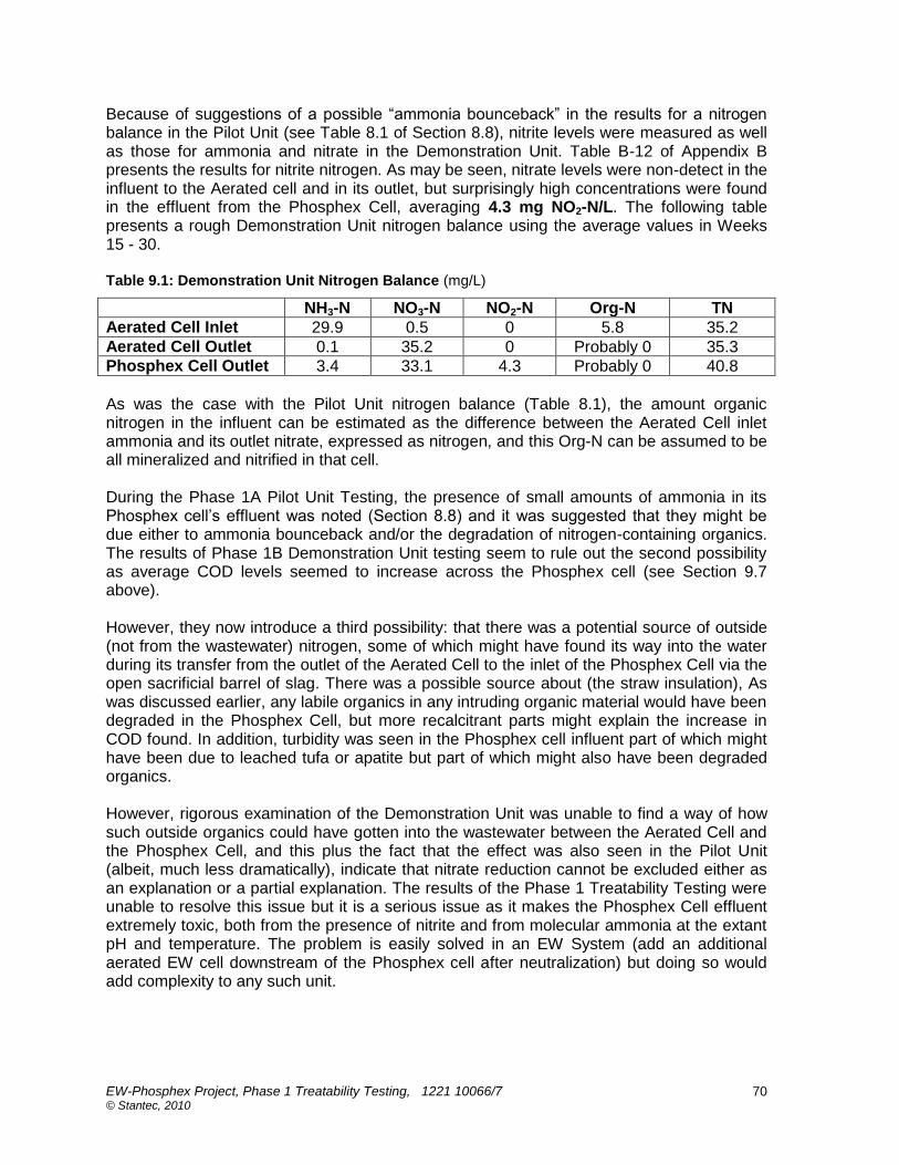
EW-Phosphex Project, Phase 1 Treatability Testing, 1221 10066/7 © Stantec, 2010
70
Because of suggestions of a possible “ammonia bounceback” in the results for a nitrogen balance in the Pilot Unit (see Table 8.1 of Section 8.8), nitrite levels were measured as well as those for ammonia and nitrate in the Demonstration Unit. Table B-12 of Appendix B presents the results for nitrite nitrogen. As may be seen, nitrate levels were non-detect in the influent to the Aerated cell and in its outlet, but surprisingly high concentrations were found in the effluent from the Phosphex Cell, averaging 4.3 mg NO2-N/L. The following table presents a rough Demonstration Unit nitrogen balance using the average values in Weeks 15 - 30. Table 9.1: Demonstration Unit Nitrogen Balance (mg/L)
NH3-N NO3-N NO2-N Org-N TN
Aerated Cell Inlet 29.9 0.5 0 5.8 35.2
Aerated Cell Outlet 0.1 35.2 0 Probably 0 35.3
Phosphex Cell Outlet 3.4 33.1 4.3 Probably 0 40.8
As was the case with the Pilot Unit nitrogen balance (Table 8.1), the amount organic nitrogen in the influent can be estimated as the difference between the Aerated Cell inlet ammonia and its outlet nitrate, expressed as nitrogen, and this Org-N can be assumed to be all mineralized and nitrified in that cell. During the Phase 1A Pilot Unit Testing, the presence of small amounts of ammonia in its Phosphex cell‟s effluent was noted (Section 8.8) and it was suggested that they might be due either to ammonia bounceback and/or the degradation of nitrogen-containing organics. The results of Phase 1B Demonstration Unit testing seem to rule out the second possibility as average COD levels seemed to increase across the Phosphex cell (see Section 9.7 above). However, they now introduce a third possibility: that there was a potential source of outside (not from the wastewater) nitrogen, some of which might have found its way into the water during its transfer from the outlet of the Aerated Cell to the inlet of the Phosphex Cell via the open sacrificial barrel of slag. There was a possible source about (the straw insulation), As was discussed earlier, any labile organics in any intruding organic material would have been degraded in the Phosphex Cell, but more recalcitrant parts might explain the increase in COD found. In addition, turbidity was seen in the Phosphex cell influent part of which might have been due to leached tufa or apatite but part of which might also have been degraded organics. However, rigorous examination of the Demonstration Unit was unable to find a way of how such outside organics could have gotten into the wastewater between the Aerated Cell and the Phosphex Cell, and this plus the fact that the effect was also seen in the Pilot Unit (albeit, much less dramatically), indicate that nitrate reduction cannot be excluded either as an explanation or a partial explanation. The results of the Phase 1 Treatability Testing were unable to resolve this issue but it is a serious issue as it makes the Phosphex Cell effluent extremely toxic, both from the presence of nitrite and from molecular ammonia at the extant pH and temperature. The problem is easily solved in an EW System (add an additional aerated EW cell downstream of the Phosphex cell after neutralization) but doing so would add complexity to any such unit.

EW-Phosphex Project, Phase 1 Treatability Testing, 1221 10066/7 © Stantec, 2010
71
9.9 Pathogen Indicators during Phase 1B Demonstration Unit Testing
Table B-13 of Appendix B presents Total Coliforms results during the Phase 1B Demonstration Unit testing and Table B-14 presents E. coli results. As may be seen from either table, levels in Holding Tank water (system influent) which ranged from values to tens of thousands to hundreds of thousands of colony forming units per 100 mL, were dramatically reduced by passing through the Aerated Cell, and whatever were left were completely removed by the Phosphex Cell. These results confirm the Pilot Unit results (see Section 8.9) and indicate that a downstream disinfection unit process would not be required in an EW System containing Phosphex cells. 9.10 Metals Removals during Phase 1B Demonstration Unit Testing
Tables B-15 to B-25 of Appendix B present results for dissolved metal concentrations during the Phase 1B Demonstration Unit testing during Weeks 15 -25 (metals analyses for Weeks 26 -32 were taken but were not available at the time of the preparation of this Report. However, they are not expected to be significantly different than those already analyzed. Table B-15 presents results for Aluminum. As may be seen there were only a few μg/L of Al in the influent to the Demonstration Unit‟s Aerated Cell (less than 5 μg Al/L for Weeks 15 – 25) and this rose to about 34 mg/L by the outlet the Aerated Cell. However, in contrast to the results found in the Pilot Unit (see Section 8.10) where aluminum levels in the outlet of the Phosphex Cell rose by over an order of magnitude, in the Demonstration Unit, effluent aluminum were halved, falling to about 18 mg Al/L. All results were still below the PWQO of 75 μ/L for the pHs extant. Table B-16 presents Pilot Unit results for Vanadium. As was the case with the pilot testing, there was little vanadium in the influent to the Aerated Cell (~ 2 μg V/L). The amount of it in the outlet of the Aerated Cell rose to over 11 μg V/L, well above the PWQO of 6 μg V/L, possibly due to some desorption from that cell‟s quartz gravel substrate. However, unlike the case with pilot testing, the level of vanadium in the effluent from the Phosphex Cell dropped to an average of 3 μg V/L for Weeks 15 -25, indicating that the addition of ZVI by its outlet was effective at mitigating any minor vanadium leaching problem from the slags in Phosphex cells. Table B-17 presents results for Zinc. As may be seen, there was only a little zinc in the feed (10 μg Zn/L) and this fell to about 4 μg Zn/L in and out of the Aerated Cell. No zinc appeared to have been leached from the substrate in the Phosphex Cell (effluent value of about 2 μg Zn/L), with all concentrations well below the PWQO. Table B-18 presents results for Iron. There was about 60 μg FeT/L in the feedstock but, as expected, most of this was removed in the Aerated Cell (down to about 7 μg FeT/L) and iron levels did not change across the Phosphex Cell. As may be seen from Table B-18, the iron analyses carried out by UoW using more precise ICP-MS equipment at the university had much lower MDLs (MDL = 0.066 μg FeT/L) than did those performed by CAWT with standard ICP-OES equipment (MDL = 5 μg FeT/L), so the averages out of the Phosphex Cell given were probably much higher than they actually were. Table B-19 presents results for Manganese. As may be seen, there was 40 - 60 μg /L of manganese in the feed and most of this was removed in the Aerated Cell (down to less than 2 μg Mn/L), and no more appears to have been leached from the slag in the Phosphex Cell. Again, as may be seen, the indicated averages out of the Phosphex Cell were probably much higher than they actually were.
EW-Phosphex Project, Phase 1 Treatability Testing, 1221 10066/7 © Stantec, 2010
72
Table B-20 presents results for Chromium. As may be seen, there was a little chromium in the feed and none appears to have been leached from the substrates in the Aerated Cell or the Phosphex Cell, with all values below the MDLs. Table B-21 presents results for Copper. As may be seen, copper concentrations in the system influent were about 16 μ/L possibly due to copper in cleaning agents used in College washrooms. There appeared to have been some copper removal in the Phosphex Cell, with average Cu concentrations in the Aerated Cell outlet falling from 16 μg/L to 4 μg/L, a reduction of about 75%. As before, copper leaching is not expected to be a problem in EW-Phosphex units and even some removal may be possible. Table B-22 presents results for Nickel. As may be seen, there was little nickel in the influent sewage (~3 μg/L) and none appeared to be leached from the substrate in the Aerated Cell but nickel concentrations in the Phosphex Cell outlet rose to almost 20 μg/L, still below the PWQO of 25 μg Ni/L, but worryingly close. Table B-23 presents results for Lead. As may be seen, there was a little lead in the feed and none appears to have been leached from the substrates in the Aerated Cell or the Phosphex Cell, with all values below the MDLs, and probably (see the UoW results) below 0.2 μg/L. Table B-24 presents results for Titanium. As may be seen, there was a little titanium in the feed and none appears to have been leached from the substrates in the Aerated Cell or the Phosphex Cell, with all values below the MDLs. Table B-25 presents results for Cadmium. Cadmium levels in the sewage influent to the Demonstration Unit were quite low, probably below 0.02 μg Cd/L (see the UoW results) and an order of magnitude below the PWQO‟s 0.2 μg Cd/L, and these levels did not change significantly across the Aerated or Phosphex Cells. 9.11 Temperatures during Phase 1B Demonstration Unit Testing
Table B-4 in Appendix B presents the temperature readings for the outlet streams for the major vessels of the Demonstration Unit during Phase 1B. A may be seen, the temperature of the streams was in the 17 - 23 ºC during the test period from Weeks 15 – 31, rising slowly as the summer proceeded. 9.12 Summary of Results for Phase 1B Demonstration Unit Testing
Again, confirming the results of the earlier Pilot Unit testing, the Phase 1B part of the EW-Phosphex Project indicated that an EW-System involving an aerated EW Cell followed by a sealed Phosphex cell will remove virtually all of phosphorus in a sewage-based wastewater (both that measured as total phosphorus and that measured as ortho-phosphate) down to trace levels. As before, it was determined that the high pH of water exiting a Phosphex cell (~11) can be controlled to acceptable levels using carbon dioxide injection. It was determined that, as expected, good removal of carbonaceous BOD can be obtained in an aerated EW cell, and that any that was left will be removed in a downstream Phosphex cell. It was confirmed that not only will a Phosphex cell remove labile organic matter reporting as cBOD, but that it will also remove at least some of the more recalcitrant, non-BOD components of chemical oxygen demand as well.

EW-Phosphex Project, Phase 1 Treatability Testing, 1221 10066/7 © Stantec, 2010
73
The Demonstration Unit Aerated Cell also removed most of the feedstock‟s ammonia, but adding the measurement of nitrite concentrations to those of ammonia and nitrate still was not able to resolve the question as to whether some nitrate reduction was occurring the Phosphex Cell. It was confirmed that a Phosphex cell will destroy any pathogens in a wastewater, indicating that an EW System containing one will not require a downstream disinfection unit. It was found that adding a layer of zero valent iron to the outlet of a Phosphex cell mitigated any vanadium leaching that might be occurring from steel slag. It was found that there was some leaching of nickel from the steel slag substrate of the Phosphex Cell and although the resulting concentrations were still below OPWQO, this metal will bear watching. When treating sewage, there should be no relevant leaching of cadmium, chromium, copper, manganese, lead, titanium or zinc from the steel slag substrates of Phosphex cells.

EW-Phosphex Project, Phase 1 Treatability Testing, 1221 10066/7 © Stantec, 2010
74
10. CONCLUSIONS AND RECOMMENDATIONS
The Phase 1A Pilot Unit was quite successful and achieved its objectives. The following are concluded from this part of the EW-Phosphex Project.
1) The concept of incorporating a Phosphex cell as a tertiary treatment cell in an EW System was demonstrated.
2) A morphology and operating plan for the subsequent Phase 1B Demonstration Unit was defined.
3) Effluent from the Phosphex Cell had the expected high pH (~11) confirming that
some sort of downstream neutralization will always be needed in an EW System containing Phosphex cells.
4) Bubbling air alone through Phosphex cell effluent is not enough to reduce its pH
significantly.
5) Carbon dioxide gas was identified as a suitable neutralizing material for Phosphex cell effluent.
6) In addition to removing phosphorus, the Pilot Unit‟s Phosphex Cell also removed
those remaining amounts of cBOD that were not removed in the upstream Aerated Cell, indicating that Phosphex cells can be expected to act in polishing roles for labile residual organics allowing EW-Phosphex systems to achieve very low effluent cBOD levels.
7) The Pilot Unit‟s Phosphex cell even removed part of the influent wastewater‟s non-
BOD organics, although the more recalcitrant parts of them (measured as COD) passed through it. (However, this was not the case during the subsequent Demonstration Unit testing.)
8) As expected, very good removals of cBOD and ammonia were achieved in the
Aerated EW Cell and the use of an aerated cell in front of a Phosphex cell was shown to be a good idea.
9) Better than 99% removals of phosphorus can be achieved in an EW-Phosphex
system.
10) Except for vanadium, metal leaching from the Phosphex Cell‟s steel slag substrate was not a problem. (It was decided to add zero valent iron material to the bottom of the Phase 1B Demo unit‟s Phosphex cell substrate to deal with this problem in the later testing.)
11) Both Aerated EW cells and Phosphex cells disinfect a wastewater passing through them, eliminating the need for separate downstream disinfection unit processes.
12) Although washing of fresh steel slag to be incorporated into a Phosphex cell‟s
substrate reduces fines and removes free lime that could plug the substrate (and should always be carried out), it does not remove all carbonate alkalinity. The free lime amount, however, does decline with time.)

EW-Phosphex Project, Phase 1 Treatability Testing, 1221 10066/7 © Stantec, 2010
75
13) The amounts of “cementing” that occurred with the Pilot Unit Phosphex Cell did not seem to reduce porosity significantly or impeded wastewater flow through it.
The Phase 1B Demonstration Unit also was quite successful and achieved its objectives. The following are concluded from this part of the EW-Phosphex Project.
1) Most of the findings of the Phase 1A Pilot Unit Testing were confirmed in the Phase 1B Demonstration Unit.
2) Adding zero valent iron near the outlet distributor of the Phosphex Cell resolved problems associated with the leaching of vanadium from the cell‟s steel slag substrate.
3) A morphology for Phase 2 testing was defined. This would involve some sort of inlet feedwater holding tank, an aerated VSSF EW cell, a sacrificial slag vessel, a Phosphex cell and some sort of downstream holding tank or basin into which carbon dioxide can be injected automatically to control effluent pH. A further downstream aerobic polishing cell might also have to be included to deal with ammonia and nitrites in Phosphex cell effluent.
4) Total and dissolved phosphorus concentrations in wastewaters being treated in EW
Systems containing Phosphex cells should be measured both filtered and unfiltered.
5) There was turbidity in the wastewater entering the Phosphex Cell of the Demonstration Unit but it was not determined if this was due to tufa, apatite, or degraded organics. The possibility of wastewater contamination with a foreign organic substance could not be eliminated, although neither could the more likely explanation, ammonia bounceback due to partial reduction of nitrate in the Phosphex Cell.
6) A “sacrificial” slag cell in front of a Phosphex Cell seemed to be successful in
limiting or preventing any tufa build up in it but operations could not be carried out long enough to confirm this.
7) The fact that Phosphex process units can disinfect as well as remove phosphorus
was verified.
The following are general recommendations from the Phase 1 EW-Phosphex Project Treatability Test from both pilot and demonstration testing.
4) Phase 2 of the EW-Phosphex Project should proceed as soon as funding can be defined.
5) The Phase 1B EW-Phosphex Demonstration Unit should continue to be operated through the winter of 2010-2011 if funding to do so can be secured. This will be needed to resolve the Phosphex cell nitrogen issue and to demonstrate operations in cold weather (the original intention before Environment Canada delays put back the Demonstration Unit schedule.)
6) Wastewater treatment facilities involving Phosphex cells need not include separate
disinfection units.

EW-Phosphex Project, Phase 1 Treatability Testing, 1221 10066/7 © Stantec, 2010
76
7) Steel slag as delivered from a steel mill always contains some fine lime between its particles (2 – 8%) and as much of this material as possible needs to be removed before the slag is used as the substrates in Phosphex cells. Outdoor storage for at least six months before use would be desirable. Slags used should be screened and washed before use and particle sizes of ¾” and greater are recommended. Fine slag material (richer in lime) should never be used as substrate in a Phosphex unit.
8) Zero valent iron should be added near the outlet of Phosphex cells constructed in
future.
9) Because of the very low levels of phosphorus in Phosphex cell effluents, analyses in ordinary analytical laboratories will be inadequate and must be arranged at facilities that can perform measurements to very low MDLs.
10) In addition to the usual analyses carried out at wastewater treatment units, those
involving Phosphex cells should include ones for TKN, TN, and nitrite, as well as filtered and un-filtered analyses for TP and ortho-phosphorus.
EW-Phosphex Project, Phase 1 Treatability Testing, 1221 10066/7 © Stantec, 2010
77
11. CLOSURE
STANTEC makes no representations or warranties respecting the results arising from the Work, either expressly or implied by law or otherwise, including but not limited to implied warranties or conditions of merchantability or fitness for a particular purpose. STANTEC shall keep confidential and not disclose to third parties the information contained in or regarding this two-volume Report for a period of three years from the coming into force of this agreement, except with the written consent of the LSRCA. STANTEC trusts that this Report meets the LSRCA‟s present requirements. If you have any questions or require additional information, please contact us at your convenience. Respectfully submitted, STANTEC CONSULTING James Higgins, Ph.D., P.Eng.