lal-pmb collaboration status · lal-pmb collaboration status and alternative solution proposal...
TRANSCRIPT
LAL-PMB Collaboration Status
and
Alternative solution proposal
Mohamed El khaldi
21/06/2018 MAC 2018_ M. EL KHALDI 1
21/06/2018 MAC 2018_ M. EL KHALDI 2
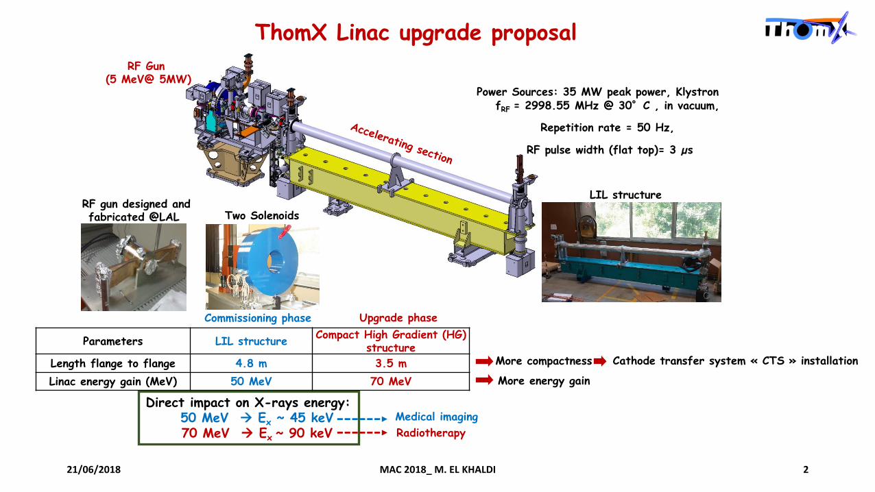
ThomX Linac upgrade proposal
fRF = 2998.55 MHz @ 30°C , in vacuum,
Repetition rate = 50 Hz,
RF pulse width (flat top)= 3 µs
Commissioning phase Upgrade phase
Direct impact on X-rays energy:50 MeV Ex ~ 45 keV70 MeV Ex ~ 90 keV
Parameters LIL structureCompact High Gradient (HG)
structure
Length flange to flange 4.8 m 3.5 m
Linac energy gain (MeV) 50 MeV 70 MeV
More compactness
More energy gain
RF Gun (5 MeV@ 5MW)
LIL structureRF gun designed and fabricated @LAL Two Solenoids
Power Sources: 35 MW peak power, Klystron
Cathode transfer system « CTS » installation
Radiotherapy
Medical imaging

Kick off meeting PMB-LAL
Research collaboration between PMB and LAL
collaboration between PMB and LAL aiming at the development of HG compact S band accelerating structure : October 2014-September. 2018
Development Phases• Prototyping: investigating all possible issues (RF, mechanical) and improving the cells machining
and brazing processes• Manufacturing of final accelerating section
LAL PMB
Electromagnetic and thermal studies, RF design Beam dynamics study
Mechanical drawings
Fabrication follow up Fabrication
High power test (RF conditioning) Tuning and lower power tests
Tasks shared between LAL and PMB
• Structure geometry optimisation (LAL)
• Fabrication process improvement (PMB)Reaching high gradient with minimum risks
of breakdown
21/06/2018 MAC 2018_ M. EL KHALDI 3
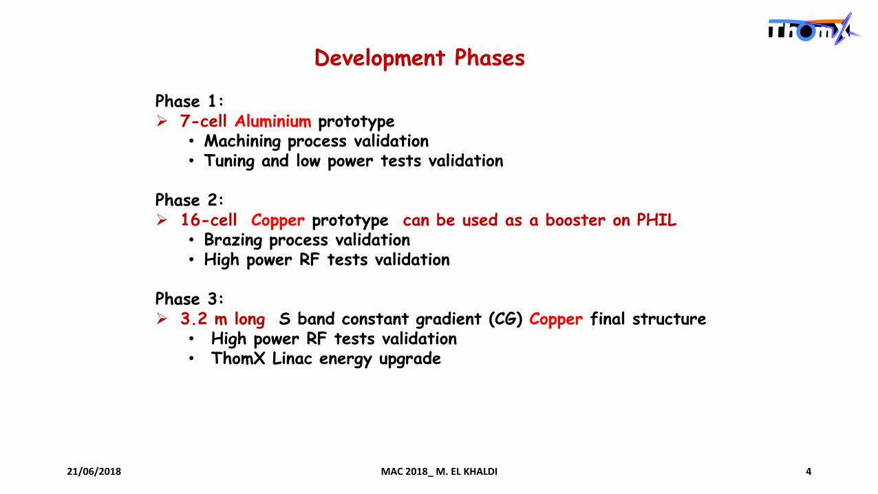
Development Phases
Phase 1: 7-cell Aluminium prototype
• Machining process validation • Tuning and low power tests validation
Phase 2: 16-cell Copper prototype can be used as a booster on PHIL
• Brazing process validation • High power RF tests validation
Phase 3: 3.2 m long S band constant gradient (CG) Copper final structure
• High power RF tests validation • ThomX Linac energy upgrade
21/06/2018 MAC 2018_ M. EL KHALDI 4

The last planning proposed by PMB: Fabrication of Aluminium and copper prototypes
21/06/2018 MAC 2018_ M. EL KHALDI 5
Second 7 cell Aluminium prototype• Design review: January 2017• Machining and fabrication: May 2017• Assembly, RF tuning and low power test: June-July 2017
Copper prototype• 3D Mechanical drawings: january 2017 • Milestone (depending on aluminium prototype results)• Machining and fabrication: June 2017• Assembly and cleaning: August 2017 • RF tuning and low power test before brazing: August 2017• Brazing, chemistry, etc : September 2017 • RF tuning and low power RF test: Octobre 2017
these steps have not been addressed

Two aluminium prototypes have been developped by PMB with difficulties : 2015-2017
Problems related to manufacturing processes: PMB uses a standard machining process
• Mechanical tolerances not respected • Presence of Manufacturing defaults• Surface flatness problems ( problems of electrical contact)
• Resonant frequency shifiting• Phase advance per cell error • Quality factor reduction => increasing RF losses
Leading to
Problems related to manufacturing processes
missing a part of aluminium corner reconstituted
with glue
degraded surface state
strange method to correct defaults
21/06/2018 MAC 2018_ M. EL KHALDI 6
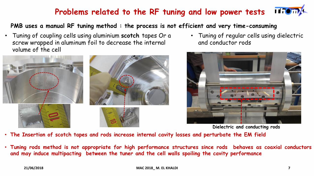
Problems related to the RF tuning and low power tests
PMB uses a manual RF tuning method : the process is not efficient and very time-consuming
• Tuning of coupling cells using aluminium scotch tapes Or a screw wrapped in aluminum foil to decrease the internal volume of the cell
• Tuning of regular cells using dielectric and conductor rods
Dielectric and conducting rods
• The Insertion of scotch tapes and rods increase internal cavity losses and perturbate the EM field
• Tuning rods method is not appropriate for high performance structures since rods behaves as coaxial conductorsand may induce multipacting between the tuner and the cell walls spoiling the cavity performance
21/06/2018 MAC 2018_ M. EL KHALDI 7

Lessons learned from this collaboration
• PMB uses standard fabrication processes (machining errors tolerance design not respected; Surface flatness problem leading to HF contact problem)
• PMB has never developped before high gradient accelerating sections
• PMB doesn’t have a high temperature brazing furnace for long accelerating sections ( > 2,5 m )
• PMB RF tuning and measurement procedures are manual and not efficient
• Manual stacking: Mechanical alignment of disks and couplers (the specified straightness tolerance ≤ 150 µm for the final structure not sure to be respected)
• Realisation of the high gradientaccelerating section would not beacheived with respect to therequired specifications
21/06/2018 MAC 2018_ M. EL KHALDI 8

Conclusions and perspectives
• Electromagnetic design (regular cell, couplers, prototypes and final accelerating section),thermal studies and cooling system design have been performed
• Beam dynamics studies using ASTRA code of the whole ThomX Linac have been performed in order tovalidate the Linac design and find an optimised working point delivering a beam with high charge, lowemittance, low energy spread, small transverse beam size,
• Aluminum prototypes have been realized with difficulties by PMB
Ph D thesis of Luca Garolfi under my supervision defended on 12 January 2018:
Future actions:
We are looking for collaborators with an extensive experience in the development of HG accelerating sections,
These prototypes are not validated by LAL
• Fabrication of a copper prototype with a reduced number of cellsThe goals of this prototype are:
test the fabrication procedure test the structure at high power
• Fabrication of 3.2 m long high-gradient S-band accelerating section
21/06/2018 MAC 2018_ M. EL KHALDI 9

21/06/2018 MAC 2018_ M. EL KHALDI 10
Plan B
Alternative solution proposal

Development of a high gradient accelerating section: 3 years min
A plan B is being considered to replace PMB company by academic partners with an extensive experiencein the development of HG accelerating sections such as Paul Scherrer Insitute (PSI)
Positive and constructive collaboration between PSI and ELETTRA
We have organized a Skype meeting with a responsible of the FERMI free electron laser linac upgrade.Elettra collaborates with PSI to produce a high gradient accelerating structure for the Fermi feel.
6.4 m long BTWS Two 3.2 m long HG structures
SLEDSLED
Klystron Klystron
• Two 3,2 m long HG structures will be installed in place of each backward traveling wave type accelerating structures (BTWS)
• The HG structure will guarantee reliable operation at 30 MV/m at 50 Hz repetition at full gradient, operating the RF plants at full power,
21/06/2018 MAC 2018_ M. EL KHALDI 11
THE FERMI UPGRADE PROPOSAL
Courtesy Claudio Serpico (ELETTRA)

To prove the reliability and the feasibility of the upgrade proposal at an accelerating gradient of 30 MV/m,a first (short) prototype has been built in collaboration with Paul Scherrer Institute (PSI, Zurich).
The prototype is made by 7 regular cells and 2 EC-couplers.
Cells and couplers are realized with Ultra-high precision machining ( specified tolerances of +/- 4 μm and measured tolerances +/- 2 μm by VDL ). ultra-precise cup machining to avoid dimple tuning.
Prototype 3D model Prototype ready for Vacuum Brazing
Prototype after brazing
21/06/2018 MAC 2018_ M. EL KHALDI
Courtesy Claudio Serpico (ELETTRA)
12
PSI-ELETTRA collaboration
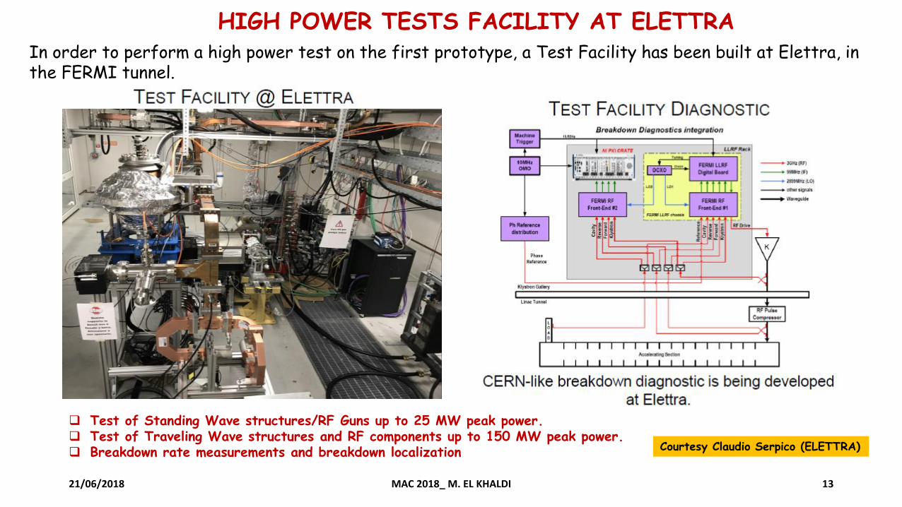
HIGH POWER TESTS FACILITY AT ELETTRA In order to perform a high power test on the first prototype, a Test Facility has been built at Elettra, in the FERMI tunnel.
21/06/2018 MAC 2018_ M. EL KHALDI 13
Courtesy Claudio Serpico (ELETTRA)
Test of Standing Wave structures/RF Guns up to 25 MW peak power. Test of Traveling Wave structures and RF components up to 150 MW peak power. Breakdown rate measurements and breakdown localization

21/06/2018 MAC 2018_ M. EL KHALDI 14
Elettra SHORT PROTOTYPE : RF CONDITIONING
RF Conditioning started on May 30. So far....
64 MW peak power, corresponding to an accelerating gradient of 27.5 MV/m.
200 ns RF pulse after Pulse Compressor (goal is 30 MV/m @ RF pulse 650 ns & repetition rate 50 Hz )
Courtesy Claudio Serpico (ELETTRA)
History Plot

21/06/2018 MAC 2018_ M. EL KHALDI 15
By the end of 2018 Elettra expect to have a set of data from the ongoing tests andexperiments which will allow Elettra to draft a detailed and complete upgrade proposal.
Courtesy Claudio Serpico (ELETTRA)
NEXT STEPS AND TIME SCHEDULE
Prove the reliability and of operating a 30 MV/m with a 50 Hz repetition rate.
In collatoration with Paul Scherrer Institute, address all the technicalissues related to the brazing of a 3 meter long accelerating structure.

21/06/2018 MAC 2018_ M. EL KHALDI
PSI’s Know How: C-BAND STRUCTURES REALIZATION4• PSI designed & developed C-Band accelerating structure, 2m long; 104 pcs for SwissFEL• Technology/production process development at PSI’s central technical unit• Diamond machining, robotic stacking, cleaning/heating/multiple brazing procedures, extended survey, vacuum and RF testing…
Robotic stacking : Assembly and alignment of stack.
16
Robot picker arm
Furnace for brazing
Courtesy PSI
Courtesy PSI

21/06/2018 MAC 2018_ M. EL KHALDI 17
Perspectives
Invitation of Claudio Serpico from Elettra to give a seminar at LAL Visite of PSI and Elettra to talk about our future collaboration