lamp controlgear - lychn.com b (normative) particular requirements for thermally protected lamp...
TRANSCRIPT
~ _____ ~ ~ ~~ ~
STD-BSI BS EN b3347-3-ENGL 2003 m L b 2 4 b b 9 0933034 BLL BRITISH STANDARD
Lamp controlgear - Part 1: General and safety requirements
The European Standard EN 61347-1:2001 has the status of a British Standard
ICs 29.140.01
BS EN
IEC 6 1347-1 :ZOO 1
6 1 34 7-1 : 2000
NO COPYING WITHOUT BSI PERMISSION EXCEPT AS PERMITTED BY COPYRIGHT LAW
COPYRIGHT 2003; European Committee for Electrotechnical Standardization
Document provided by IHS Licensee=Underwriters Laboratories Inc /5909636100,User=, 06/20/2003 02:01:07 MDT Questions or comments about this message: pleasecall the Document Policy Management Group at 1-800-451-1584.
--```,`,,`,```,,`````,,,`,,,`,,-`-`,,`,,`,`,,`---
STD-BSI BS EN bL347-L-ENGL 2OOL E Lb2Ltbb9 0933075 758 E BS EN 61347-1~2001
Amd.No. Date
National foreword
Comments
This British Standard is the official English language version of EN 61347-1:2001. It is identical with IEC 61347-1:2000.Together with BS EN 61347-2-1:2001 it supersedes BS EN 60926:1996; with BS EN 61347-2-2:2001 it supersedes BS EN 61046:1995; with BS EN 61347-2-3:2001 it supersedes BS EN 60928:1995; with BS EN 61347-2-4, 2-5, 2-6 and 2-7:2001 it supersedes BS EN 60924:1991; with BS EN 61347-2-8:2001 it supersedes BS EN 60920:1991 and with BS EN 61347-2-9:2001 it supersedes BS EN 60922:1997. All these superseded parts will be withdrawn on 1 November 2003. The UK participation in its preparation was entrusted by Technical Committee CPLí34, Lamps and related equipment, to Subcommittee CPLí34/3, Auxiliaries for Lamps, which has the responsibility to:
This British Standard, having been prepared under the direction of the Electrotechnical Sector Committee, was published under the authority of the Standards Committee and comes into effect on 15 May 2001
-
-
aid enquirers to understand the text;
present to the responsible internationaUEuropean committee any enquiries on the interpretation, or proposals for change, and keep the UK interests informed;
monitor related international and European developments and promulgate them in the UK.
-
A list of organizations represented on this subcommittee can be obtained on request to its secretary. From 1 January 1997, all IEC publications have the number 60000 added to the old number. For instance, IEC 27-1 has been renumbered as IEC 60027-1. For a period of time during the change over from one numbering system to the other, publications may contain identifiers from both systems. Cross-references Attention is drawn to the fact that CEN and CENELEC Standards normally include a n annex which lists normative references to international publications with their corresponding European publications. The British Standards which implement these international or European publications may be found in the BSI Standards Catalogue under the section entitled “International Standards Correspondence Index”, or by using the “Find” facility of the BSI Standards Electronic Catalogue. A British Standard does not purport to include all the necessary provisions of a contract. Users of British Standards are responsible for their correct application. Compliance with a British Standard does not of itself confer immunity from legal obligations. Summary of pages This document comprises a front cover, a n inside front cover, the EN title page, pages 2 to 59 and a back cover. The BSI copyright date displayed in this document indicates when the document was last issued.
O BSI 05-2001
ISBN O 580 37386 X
COPYRIGHT 2003; European Committee for Electrotechnical Standardization
Document provided by IHS Licensee=Underwriters Laboratories Inc /5909636100,User=, 06/20/2003 02:01:07 MDT Questions or comments about this message: pleasecall the Document Policy Management Group at 1-800-451-1584.
--```,`,,`,```,,`````,,,`,,,`,,-`-`,,`,,`,`,,`---

EUROPEAN STANDARD EN 61347-1 NORME EUROPÉENNE
EUROPAISCHE NORM January 2001
ICC 29.140.99
English version
Lamp controlgear Part I: General and safety requirements
(IEC 61 347-1 12000)
Appareillages de lampes Partie 1 : Prescriptions générales et prescriptions de sécurité (CE1 61 347-1 12000)
Geräte für Lampen Teil 1 : Allgemeine und Sicherheitsanforderungen (IEC 61 347-1 12000)
This European Standard was approved by CENELEC on 2000-1 1-01. CENELEC members are bound to comply with the CENKENELEC Internal Regulations which stipulate the conditions for giving this European Standard the status of a national standard without any alteration.
Up-to-date lists and bibliographical references concerning such national standards may be obtained on application to the Central Secretariat or to any CENELEC member.
This European Standard exists in three official versions (English, French, German). A version in any other language made by translation under the responsibility of a CENELEC member into its own language and notified to the Central Secretariat has the same status as the official versions.
CENELEC members are the national electrotechnical committees of Austria, Belgium, Czech Republic, Denmark, Finland, France, Germany, Greece, Iceland, Ireland, Italy, Luxembourg, Netherlands, Norway, Portugal, Spain, Sweden, Switzerland and United Kingdom.
CENELEC European Committee for Electrotechnical Standardization
Comité Européen de Normalisation Electrotechnique Europäisches Komitee fur Elektrotechnische Normung
Central Secretariat: rue de Stassart 35, B - 1050 Brussels
O 2001 CENELEC - All rights of exploitation in any form and by any means reserved worldwide for CENELEC members.
Ref. No. EN 61347-1:2001 E
COPYRIGHT 2003; European Committee for Electrotechnical Standardization
Document provided by IHS Licensee=Underwriters Laboratories Inc /5909636100,User=, 06/20/2003 02:01:07 MDT Questions or comments about this message: pleasecall the Document Policy Management Group at 1-800-451-1584.
--```,`,,`,```,,`````,,,`,,,`,,-`-`,,`,,`,`,,`---
Page 2 EN 61347-1:2001
Foreword
The text of document 34C/508/FDIS, future edition 1 of IEC 61347-1, prepared by SC 34C, Auxiliaries for lamps, of IEC TC 34, Lamps and related equipment, was submitted to the IEC- CENELEC parallel vote and was approved by CENELEC as EN 61347-1 on 2000-11-01.
This EN 61347-1, together with the parts 2-1 to 2-9 of EN 61347, supersedes EN 60920, EN 60922, EN 60924, EN 60926, EN 60928 and EN 61046.
The following dates were fixed:
- latest date by which the EN has to be implemented at national level by publication of an identical national standard or by endorsement
- latest date by which the national standards conflicting with the EN have to be withdrawn
(dOp) 2001-08-01
(dow) 2003-1 1-01
This part 1 of EN 61347 is to be used in conjunction with the appropriate part 2, which contains clauses to supplement or modify the corresponding clauses in part 1 to provide the relevant requirements for each type of product.
NOTE In this standard, the following print types are used: - requirements: in roman type; - fesf specifications: in italic type; - notes: in smaller roman type.
Annexes designated "normative" are part of the body of the standard. In this standard, annexes A to H and ZA are normative. Annex ZA has been added by CENELEC.
Endorsement notice
The text of the International Standard IEC 61 347-1 :2000 was approved by CENELEC as a European Standard without any modification.
COPYRIGHT 2003; European Committee for Electrotechnical Standardization
Document provided by IHS Licensee=Underwriters Laboratories Inc /5909636100,User=, 06/20/2003 02:01:07 MDT Questions or comments about this message: pleasecall the Document Policy Management Group at 1-800-451-1584.
--```,`,,`,```,,`````,,,`,,,`,,-`-`,,`,,`,`,,`---

STD*BSI BS EN b3347-1-ENGL 2001 3624bb9 0933078 4b7 W Page 3
EN 61347-1:2001
CONTENTS
Page
INTRODUCTION .................................................................................................................... 5
Clause 1 2 3 4 5 6 7
0 9 10 11 12 13 14 15
16 17 18 19
Scope .............................................................................................................................. 6 Normative references ....................................................................................................... 6 Definitions ....................................................................................................................... 7 General requirements ..................................................................................................... 11 General notes on tests .................................................................................................... 11 Classification .................................................................................................................. 12 Marking .......................................................................................................................... 12 7.1 Items to be marked ................................................................................................ 12 7.2 Durability and legibility of marking ......................................................................... 13 Terminals ........................................................................................................................ 13 Provisions for protective earthing .................................................................................... 14 Protection against accidental contact with live parts ....................................................... 14 Moisture resistance and insulation .................................................................................. 15 Electric strength .............................................................................................................. 15 Thermal endurance test for windings of ballasts .............................................................. 16 Fault conditions .............................................................................................................. 19 Construction ................................................................................................................... 21 15.1 Wood, cotton, silk, paper and similar fibrous material ............................................ 21 15.2 Printed circuits ....................................................................................................... 21 Creepage distances and clearances ............................................................................... 22 Screws, current-carrying parts and connections .............................................................. 24 Resistance to heat, fire and tracking ............................................................................... 24 Resistance to corrosion .................................................................................................. 25
Annex A (normative) Test to establish whether a conductive part is a live part which may cause an electric shock ................................................................................................. 28 Annex B (normative) Particular requirements for thermally protected lamp controlgear ......... 29 Annex C (normative) Particular requirements for electronic lamp controlgear with means of protection against overheating ............................................................................... 36 Annex D (normative) Requirements for carrying out the heating tests of thermally protected lamp controlgear .................................................................................................... 39 Annex E (normative) Use of constant S other than 4 500 in t , tests ...................................... 42 Annex F (normative) Draught-proof enclosure ...................................................................... 45 Annex G (normative) Explanation of the derivation of the values of pulse voltages ............... 46 Annex H (normative) Tests ................................................................................................... 51 Annex ZA (normative) Normative references to international publications with their
corresponding European publications ............................................................................. 58
Bibliography .......................................................................................................................... 57
O BSI 05-2001
COPYRIGHT 2003; European Committee for Electrotechnical Standardization
Document provided by IHS Licensee=Underwriters Laboratories Inc /5909636100,User=, 06/20/2003 02:01:07 MDT Questions or comments about this message: pleasecall the Document Policy Management Group at 1-800-451-1584.
--```,`,,`,```,,`````,,,`,,,`,,-`-`,,`,,`,`,,`---

STD-BSI BS EN bL347-L-ENGL 2OOL = L624667 0733079 3T3 Page 4 EN 61347-1:2001
Page
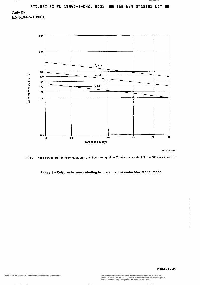
Figure 1 . Relation between winding temperature and endurance test duration ..................... 26
connected to the supply mains .............................................................................................. 27 Figure D. l - Exemple of heating enclosure for thermally protected ballasts .......................... 41
Figure G.1 - Circuit for measuring short-duration pulse energy ............................................. 49
Figure H . l - Test arrangement for heating test ..................................................................... 56
Figure 2 . Creepage distances between conductors on printed boards not conductively
Figure E.1 - Assessment of claimed value of S ..................................................................... 44
Figure G.2 - Suitable circuit for producing and applying long-duration pulses ....................... 50
Table 1 . Electric strength test voltage ................................................................................. 16
Table 2 - Theoretical test temperatures for ballasts subjected to an endurance test duration of 30 days ............................................................................................................... 18 Table 3 - Minimum distances for a.c. (50/60 Hz) sinusoidal voltages .................................... 23
Table B . l - Thermal protection operation .............................................................................. 33
Table 6.2 - Thermal protection operation .............................................................................. 34
Table 4 - Minimum distances for non-sinusoidal pulse voltages ............................................ 23
O BSI 05-2001
~
COPYRIGHT 2003; European Committee for Electrotechnical Standardization
Document provided by IHS Licensee=Underwriters Laboratories Inc /5909636100,User=, 06/20/2003 02:01:07 MDT Questions or comments about this message: pleasecall the Document Policy Management Group at 1-800-451-1584.
--```,`,,`,```,,`````,,,`,,,`,,-`-`,,`,,`,`,,`---

STD-BSI BS EN 61347-3-ENGL 2001 W 3624669 0933080 035 Page 5
EN 61347-1~2001
INTRODUCTION
This first edition of IEC 61347-1, published in conjunction with parts 2-1 to 2-9, represents an editorial review IEC 60926, IEC 61046, IEC 60928, IEC 60924, IEC 60920 and IEC 60922. The formatting into separately published parts provides for ease of future amendments and revisions. Additional requirements will be added as and when a need for them is recognized.
The different parts which make up IEC 61347-2 are technically equivalent to the original IEC standards on which they are based. As such, products which have been shown to comply with IEC 60920, IEC 60922, IEC 60924, IEC 60926, IEC 60928 and IEC 61046 can be considered as complying with the requirements of the part 2 of IEC 61347 which replaces them. Similarly, where other standards call for compliance with IEC 60920, IEC 60922, IEC 60924, IEC 60926, IEC 60928 and IEC 61046, conformity with the equivalent part 2 of IEC 61347 is considered to meet this requirement.
This part of IEC 61347 provides a set of general and safety requirements and tests which are considered to be generally applicable to most types of lamp controlgear and which can be called up as required by the different parts that make up IEC 61347-2. This part 1 is thus not to be regarded as a specification in itself for any type of lamp controlgear, and its provisions apply only to particular types of lamp controlgear, to the extent determined by the appropriate part 2 of IEC 61347.
The parts which make up IEC 61347-2, in referring to any of the clauses of this part, specify the extent to which such a clause is applicable and the order in which the tests are to be performed; they also include additional requirements as necessary. The order in which the clauses of this part are numbered has no particular significance, as the order in which their provisions apply is determined for each type of lamp controlgear by the appropriate part 2 of IEC 61347-2 series. All such parts are self-contained and therefore do not contain references to each other.
Where the requirements of any of the clauses of this part of IEC 61347 are referred to in the various parts that make up IEC 61347-2 by the phrase "The requirements of clause n of IEC 61347-1 apply", this phrase will be interpreted as meaning that all requirements of the clause in question of part 1 apply, except any which are clearly inapplicable to the particular type of lamp controlgear covered by the part 2 concerned.
Lamp controlgear which complies with the text of this standard will not necessarily be judged to comply with the safety principles of the standard if, when examined and tested, it is found to have other features which impair the level of safety covered by these requirements.
Lamp controlgear employing materials or having forms of construction differing from those detailed in the requirements of this standard may be examined and tested according to the intent of the requirement and, if found to be substantially equivalent, may be judged to comply with the safety principles of the standard.
Performance requirements for lamp controlgear are the subject of IEC 60921, IEC 60923, IEC60925, IEC 60927, IEC 60929 and IEC 61047 as appropriate for the type of lamp controlgear.
NOTE Safety requirements ensure that electrical equipment constructed in accordance with these requirements does not endanger the safety of persons, domestic animals or property when properly installed and maintained and used in applications for which it was intended.
Requirements for electronic lamp controlgear for other types of lamps will be the subject of a separate standard, as the need arises.
O BSI 05-2001
COPYRIGHT 2003; European Committee for Electrotechnical Standardization
Document provided by IHS Licensee=Underwriters Laboratories Inc /5909636100,User=, 06/20/2003 02:01:07 MDT Questions or comments about this message: pleasecall the Document Policy Management Group at 1-800-451-1584.
--```,`,,`,```,,`````,,,`,,,`,,-`-`,,`,,`,`,,`---

STD-BSI BS EN bL347-L-ENGL 2001 Lb24669 09L308L T5L Page 6 EN 61347-1:2001
LAMP CONTROLGEAR - Part 1 : General and safety requirements
i Scope
This part of IEC 61347 specifies general and safety requirements for lamp controlgear for use on d.c. supplies up to 250 V and/or a.c. supplies up to 1 O00 V at 50 Hz or 60 Hz.
This standard also covers lamp controlgear for lamps which are not yet standardized.
Tests dealt with in this standard are type tests. Requirements for testing individual lamp controlgear during production are not included.
Requirements for semi-luminaires are given in IEC 60598.
In addition to the requirements given in this standard, annex B sets out general and safety requirements applicable to thermally protected lamp controlgear.
Annex C sets out additional general and safety requirements as they apply to electronic lamp controlgear with means of protection against overheating.
2 Normative references
The following normative documents contain provisions which, through reference in this text, constitute provisions of this part of IEC 61347. For dated references, subsequent amendments to, or revisions of, any of these publications do not apply. However, parties to agreements based on this part of IEC 61347 are encouraged to investigate the possibility of applying the most recent editions of the normative documents indicated below. For undated references, the latest edition of the normative document referred to applies. Members of IEC and IS0 maintain registers of currently valid International Standards.
IEC 60065, Audio, video and similar electronic apparatus - Safety requirements
IEC 60081, Double-capped fluorescent lamps - Performance specifications
IEC 60112, Method for determining the comparative and the proof tracking indices of solid insulating materials under moist conditions
IEC 60249 (all parts), Base materials for printed circuits
IEC 60249-1, Base materials for printed circuits - Part I: Test methods
IEC 60317-0-1, Specifications for particular types of winding wires - Part O: General requirements - Section I : Enamelled round copper wire
IEC 6041 7 (all parts), Graphical symbols for use on equipment
IEC 60529, Degrees of protection provided by enclosures (IP Code)
IEC 60598-1, Luminaires - Part I : General requirements and tests
IEC 60691, Therms/-links - Requirements and application guide
O BSI 05-2001
COPYRIGHT 2003; European Committee for Electrotechnical Standardization
Document provided by IHS Licensee=Underwriters Laboratories Inc /5909636100,User=, 06/20/2003 02:01:07 MDT Questions or comments about this message: pleasecall the Document Policy Management Group at 1-800-451-1584.
--```,`,,`,```,,`````,,,`,,,`,,-`-`,,`,,`,`,,`---
STD.BSI BS EN bl347-1-ENGL 2003 Lb24bb î 0933082 998 Page 7
EN 61347-k2001
IEC 60695-2-1/0, Fire hazard testing - Part 2: Test methods - Section I/sheet O: Glow-wire test methods - General
IEC 60695-2-2, Fire hazard testing - Part 2: Test methods - Section 2: Needle-flame test
IEC 60730-2-3, Automatic electrical controls for household and similar use - Part 2: Particular requirements for thermal protectors for ballasts for tubular fluorescent lamps
I EC 60901, Single-capped fluorescent lamps - Performance specifications
IEC 60921, Ballasts for tubular fluorescent lamps - Performance requirements
IEC 60923, Auxiliaries for lamps - Ballasts for discharge lamps (excluding tubular fluorescent lamps) - Performance requirements
IEC 60929, AC supplied electronic ballasts for tubular fluorescent lamps - Performance requirements
I EC 60990, Methods of measurement of touch-current and protective conductor current
IEC 61347-2-2, Lamp controlgear - Part 2-2: Particular requirements for d.c. or a.c. supplied electronic step-down convertors for filament lamps 1)
IEC 61 347-2-8, Lamp controlgear - Part 2-8: Particular requirements for ballasts for fluorescent lamps 1
IEC 61 347-2-9, Lamp controlgear - Part 2-9: Particular requirements for ballasts for discharge lamps (excluding fluorescent lamps) I)
IS0 4046:1978, Paper, board, pulp and related terms - Vocabulary
3 Definitions
For the purpose of this part of IEC 61347, the following definitions apply.
3.1 lamp controlgear one or more components between the supply and one or more lamps which may serve to transform the supply voltage, limit the current of the lamp(s) to the required value, provide starting voltage and preheating current, prevent cold starting, correct power factor or reduce radio interference.
3.1.1 built-in lamp controlgear lamp controlgear generally designed to be built into a luminaire, a box, an enclosure or the like and not intended to be mounted outside a luminaire, etc. without special precautions. The controlgear compartment in the base of a road lighting column is considered to be an enclosure
1) To be published.
O BSI 05-2001 COPYRIGHT 2003; European Committee for Electrotechnical Standardization
Document provided by IHS Licensee=Underwriters Laboratories Inc /5909636100,User=, 06/20/2003 02:01:07 MDT Questions or comments about this message: pleasecall the Document Policy Management Group at 1-800-451-1584.
--```,`,,`,```,,`````,,,`,,,`,,-`-`,,`,,`,`,,`---

3.1.2 independent lamp controlgear lamp controlgear consisting of one or more separate elements so designed that it can be mounted separately outside a luminaire, with protection according to the marking of the lamp controlgear and without any additional enclosure. This may consist of a built-in lamp controlgear housed in a suitable enclosure which provides all the necessary protection according to its markings
3.1.3 integral lamp controlgear lamp controlgear which forms a non-replaceable part of a luminaire and which cannot be tested separately from the luminaire
3.2 ballast
unit inserted between the supply and one or more discharge lamps which by means of inductance, capacitance, or a combination of inductance and capacitance, serves mainly to limit the current of the lamp(s) to the required value.
It may also include means for transforming the supply voltage and arrangements which help provide starting voltage and pre-heating current
3.2.1 d.c. supplied electronic ballast d.c. to a.c invertor using semiconductor devices which may include stabilizing elements for supplying power to one or more fluorescent lamps
3.2.2 reference ballast special inductive ballast designed for the purpose of providing comparison standards for use in testing ballasts and for the selection of reference lamps. It is essentially characterized by a stable voltage-to-current ratio, which is relatively uninfluenced by variations in current, temperature and magnetic surroundings, as outlined in annex C of IEC 60921 and annex A of IEC 60923
3.3 reference lamp lamp selected for testing ballasts which, when associated with a reference ballast, has electrical characteristics which are close to the nominal values as stated in the relevant lamp standard
3.4 calibration current of a reference ballast value of the current on which are based the calibration and control of the reference ballast NOTE which the reference ballast is suitable. '
Such a current should preferably be approximately equal to the nominal running current of the lamps for
3.5 supply voltage voltage applied to the complete circuit of lamp(s) and lamp controlgear
3.6 working voltage highest r.m.s. voltage which may occur across any insulation at rated supply voltage, transients being neglected, in open-circuit conditions or during normal operation
O BSI 05-2001
COPYRIGHT 2003; European Committee for Electrotechnical Standardization
Document provided by IHS Licensee=Underwriters Laboratories Inc /5909636100,User=, 06/20/2003 02:01:07 MDT Questions or comments about this message: pleasecall the Document Policy Management Group at 1-800-451-1584.
--```,`,,`,```,,`````,,,`,,,`,,-`-`,,`,,`,`,,`---
~~ ~
~
STD*BSI ES EN bL347-1-ENGL 2001 = 1624667 0913084 7b0 Page 9
EN 61347-1~2001
3.7 design voltage voltage declared by the related. This value is not
manufacturer to which all the lamp controlgear characteristics are less than 85 % of the maximum value of the rated voltage range
3.8 voltage range range of supply voltage over which the ballast is intended to be operated
3.9 supply current current supplied to the complete circuit of lamp@) and lamp controlgear
3.10 live part conductive pari which may cause an electric shock in normal use. The neutral conductor is, however, regarded as a live part NOTE The test to determine whether or not a conductive part is a live part which may cause an electric shock is given in annex A.
3.1 1 type test test or series of tests made on a type-test sample for the purpose of checking compliance of the design of a given product with the requirements of the relevant standard
3.12 type-test sample sample consisting of one or more similar units submitted by the manufacturer or responsible vendor for the purpose of a type test
3.1 3 circuit power factor A, power factor of the combination of lamp controlgear and the lamp or lamps for which the lamp controlgear is designed
3.14 high power factor ballast ballast having a circuit power factor of at least 0,85 (leading or lagging) NOTE 1 The value 0,85 takes into account the distortion of the current waveform.
NOTE 2 For North America, a high power factor is defined as a power factor of at least 0,9.
3.1 5 rated maximum temperature fc highest permissible temperature which may occur on the outer surface (at the indicated place, if marked) under normal operating conditions and at the rated voltage or the maximum of the rated voltage range
3.16 rated maximum operating temperature of a lamp controlgear winding
winding temperature assigned by the manufacturer as the highest temperature at which 50/60 Hz lamp controlgear may be expected to have a service life of at least 10 years' continuous operation
tw
O BSI 05-2001
COPYRIGHT 2003; European Committee for Electrotechnical Standardization
Document provided by IHS Licensee=Underwriters Laboratories Inc /5909636100,User=, 06/20/2003 02:01:07 MDT Questions or comments about this message: pleasecall the Document Policy Management Group at 1-800-451-1584.
--```,`,,`,```,,`````,,,`,,,`,,-`-`,,`,,`,`,,`---

STD-BSI BS EN 61347-1-ENGL 2001 I 1624669 0923085 bT7 m Page 10 EN 61347-1~2001
3.17 rectifying effect effect which may occur at the end of lamp life when one cathode is either broken or has insufficient electron emission, resulting in the arc current being constantly unequal in consecutive half-cycles
3.18 test duration of endurance test D optional duration of the endurance test on which the temperature conditions are based
3.19 degradation of insulation of a ballast winding S constant which determines the degradation of ballast insulation
3.20 ignitor device intended to generate voltage pulses to start discharge lamps and which does not provide for the preheating of electrodes NOTE The element that releases the starting voltage pulse may be either triggered or non-triggered.
3.21 protective earth (ground)
@ (5019 of IEC 60417) terminal to which are connected parts which are connected to earth for safety reasons
3.22 functional earth (ground)
(5017 of IEC 60417) terminal to which are connected parts which may be necessary to connect to earth for reasons other than safety NOTE 1 In some instances, starting aids adjacent to the lamp(s) are connected to one of the output terminals but need not be connected to the earth on the supply side.
NOTE 2 In some cases, functional earthing may be necessary to facilitate starting or for e.m.c. purposes.
3.23 frame (chassis)
(5020 of IEC 60417) terminal whose potential is taken as reference
O BSI 05-2001
COPYRIGHT 2003; European Committee for Electrotechnical Standardization
Document provided by IHS Licensee=Underwriters Laboratories Inc /5909636100,User=, 06/20/2003 02:01:07 MDT Questions or comments about this message: pleasecall the Document Policy Management Group at 1-800-451-1584.
--```,`,,`,```,,`````,,,`,,,`,,-`-`,,`,,`,`,,`---

STD-BSI BS EN bL347-L-ENGL 2001 = 1624669 09130Bb 533 W Page 11
EN 61347-1:2001
4 General requirements
Lamp controlgear shall be so designed and constructed that in normal use it operates without danger to the user or surroundings.
Compliance is checked by carrying out all the tests specified.
In addition, independent lamp controlgear shall comply with the requirements of IEC 60598-1, including the classification and marking requirements of that standard such as IP classification, v m a r k i n g , etc.
5 General n o t e s o n tests
5.1
NOTE The requirements and tolerances permitted by this standard are related to testing of a type-test sample submitted by the manufacturer for that purpose. Compliance of the type-test sample does not ensure compliance of the whole production of a manufacturer with this safety standard.
Conformity of production is the responsibility of the manufacturer and may include routine tests and quality assurance in addition to type testing.
Tests according to this standard are type tests.
5.2 to 30 OC.
Unless otherwise specified, the tests are carried out at an ambient temperature of 10 "C
5.3 or more items submitted for the purpose of the type test.
Unless otherwise specified, the type test is carried out on one sample consisting of one
In general, all tests are carried out on each type of lamp controlgear or, where a range of similar lamp controlgear is involved, for each wattage in the range or on a representative selection from the range, as agreed with the manufacturer.
Certain countries require that three samples of lamp controlgear be tested and, in such cases, if more than one sample fails, then the type is rejected. If one sample fails, the test is repeated using three other samples and all of these shall comply with the test requirements.
5.4 The tests shall be carried out in the order listed in this standard unless otherwise specified in parts 2 of IEC 61347.
5.5 For the thermal test, independent lamp controlgear shall be mounted in a test corner consisting of three dull-black painted wooden/wood fibre boards 15 mm to 20 mm thick and arranged so as to resemble two walls and the ceiling of a room. The lamp controlgear is secured to the ceiling as close as possible to the walls, the ceiling extending at least 250 mm beyond the other side of the lamp controlgear.
5.6 For d.c. supplied ballasts intended for use from a battery supply it is permissible to substitute a d.c. power source other than a battery, provided that the source impedance is equivalent to that of a battery.
NOTE A non-inductive capacitor of appropriate rated voltage and with a capacitance of at least 50 pF, connected across the supply terminals of the unit under test normally provides a source impedance simulating that of a battery.
O BSI 05-2001 COPYRIGHT 2003; European Committee for Electrotechnical Standardization
Document provided by IHS Licensee=Underwriters Laboratories Inc /5909636100,User=, 06/20/2003 02:01:07 MDT Questions or comments about this message: pleasecall the Document Policy Management Group at 1-800-451-1584.
--```,`,,`,```,,`````,,,`,,,`,,-`-`,,`,,`,`,,`---
-~
STDmBSI BS EN b3347-3-ENGL 2OlJ3 = Lb24667 0733087 Y7T W Page 12 EN 61347-1:2001
6 Classification
Lamp controlgear is classified, according to the method of installation, as
- built-in;
- independent;
- integral.
7 Marking
7.1 Items to be marked
The parts that make up IEC 61347-2 state which of the following items shall be marked as mandatory markings or provided as information to be given either on the lamp controlgear or made available in the manufacturer's catalogue or similar.
a) Mark of origin (trade mark, manufacturer's name or name of the responsible vendor/ sup pl ¡er ) .
b) Model number or type reference of the manufacturer.
c) Symbol for independent lamp controlgear 0 if applicable.
d) The correlation between replaceable and interchangeable parts, including fuses, of lamp controlgear shall be marked unambiguously by legends on the lamp controlgear or, with the exception of fuses, be specified in the manufacturer's catalogue.
e) Rated supply voltage (or voltages, if there are several), voltage range, supply frequency and supply current(s); the supply current may be given in the manufacturer's literature.
f) The earthing terminals (if any) shall be identified by the symbol, O - A , or These symbols shall not be placed on screws or other easily removable parts.
g) The claimed value of the rated maximum operating temperature of the winding following the symbol fw, values increasing in multiples of 5 OC.
h) Indication that the lamp controlgear does not rely upon the luminaire enclosure for protection against accidental contact with live parts.
i) Indication of the cross-section of conductors for which the terminals, if any, are suitable.
Symbol: relevant value(s) in square millimetres (mm2) followed by a small square.
j ) The lamp type and rated wattage or wattage range for which the lamp controlgear is suitable, or the designation as indicated on the lamp data sheet of the type(s) of lamp(s) for which the lamp controlgear is designed. If the lamp controlgear is intended to be used with more than one lamp, the number and rated wattages of each lamp shall be indicated.
NOTE 1 all ratings within the range unless otherwise indicated in the manufacturer's literature.
For lamp controlgear specified in IEC 61347-2-2, it is assumed that a marked wattage range includes
O BSI 05-2001
COPYRIGHT 2003; European Committee for Electrotechnical Standardization
Document provided by IHS Licensee=Underwriters Laboratories Inc /5909636100,User=, 06/20/2003 02:01:07 MDT Questions or comments about this message: pleasecall the Document Policy Management Group at 1-800-451-1584.
--```,`,,`,```,,`````,,,`,,,`,,-`-`,,`,,`,`,,`---
STD-BSI BS EN bL347-1-ENGL 2001 D Lb24669 0913088 306 Page 13
EN 61347-1:2001
k) Wiring diagram indicating the position and purpose of terminals. In the case of lamp controlgear having no terminals, a clear indication shall be given on the wiring diagram of the significance of the code used for connecting wires. Lamp controlgear that operates in specific circuits only shall be identified accordingly, for example by marking or wiring diagram.
I) Value of tc.
If this relates to a certain place on the lamp controlgear, this place shall be indicated or specified in the manufacturer's catalogue.
m) Symbol for temperature declared, thermally protected c o n t r o l g e a r v (see annex 6). The dots in the triangle shall be replaced by the value of the rated maximum case temperature in degrees Celsius assigned by the manufacturer, values increasing in multiples of I O.
n) Heat sink(s) required additional to the lamp controlgear.
o) The limiting temperature of the winding under abnormal conditions which shall be respected when the controlgear is built into a luminaire, as information for luminaire design.
NOTE 2 In the case of lamp controlgear intended for circuits which do not produce abnormal conditions, or are for use only with starting devices which exempt the lamp controlgear from the abnormal conditions of annex C of IEC 60598-1, the winding temperature under abnormal conditions is not indicated.
p) The test period for the endurance test for lamp controlgear which, at the manufacturer's choice, shall be tested for a period longer than 30 days, may be indicated with the symbol D, followed by the appropriate number of days, 60, 90 or 120 in IO-day periods, the whole being placed between the brackets immediately after the tw indication. For example, (D6) for controlgear to be tested for a period of 60 days.
NOTE 3 The standard endurance test period of 30 days need not be indicated.
q) For lamp controlgear for which a constant S other than 4 500 is claimed by the manu- facturer, the symbol S together with its appropriate value in thousands, for example "S6", if S has a value of 6 000.
NOTE 4 Preferred values of S are: 4 500, 5 000, 6 000, 8 000, 11 000, 16 000.
7.2
Marking shall be durable and legible.
Durability and legibility of marking
Compliance is checked by inspection and by trying to remove the marking by rubbing lightly, for 75 s each time, with two pieces of cloth, one soaked with water and the other with petroleum spirit.
The marking shall be legible after the test.
NOTE The petroleum spirit used should consist of a solvent hexane with a content of aromatics of maximum 0, l % volume percentage, a kauri-butanol value of 29, an initial boiling-point of approximately 65 "C, a dry-point of approximately 69 "C and a density of approximately 0.68 g/cm3.
8 Terminals
Screw terminals shall comply with section 14 of IEC 60598-1.
Screwless terminals shall comply with section 15 of IEC 60598-1
O BSI 05-2001
COPYRIGHT 2003; European Committee for Electrotechnical Standardization
Document provided by IHS Licensee=Underwriters Laboratories Inc /5909636100,User=, 06/20/2003 02:01:07 MDT Questions or comments about this message: pleasecall the Document Policy Management Group at 1-800-451-1584.
--```,`,,`,```,,`````,,,`,,,`,,-`-`,,`,,`,`,,`---
STDaBSI BS EN b3347-1-ENGL 2001 = Lb24bb9 0933089 242 Page 14 EN 61347-1:2001
9 Provisions for protective earthing
Earthing terminals shall comply with the requirements of clause 8. The electrical connection/ clamping means shall be adequately locked against loosening, and it shall not be possible to loosen the electrical connection/clamping means by hand without the use of a tool. For screwless terminals, it shall not be possible to loosen the clamping meanclelectrical connection unintentionally.
Earthing of lamp controlgear (other than independent lamp controlgear) via means of fixing the lamp controlgear to earthed metal is permitted. However, if a lamp controlgear has an earthing terminal, this terminal shall only be used for earthing the lamp controlgear.
All parts of an earthing terminal shall be such as to minimize the danger of electrolytic corrosion resulting from contact with the earth conductor or any other metal in contact with them.
The screw and the other parts of the earthing terminal shall be made of brass or other metal no less resistant to corrosion, or material with a non-rusting surface and at least one of the contact surfaces shall be bare metal.
Compliance is checked by inspection, by manual test and according to the requirements of clause 8.
Lamp controlgear with conductors for protective earthing provided by tracks on printed circuit boards shall be tested as follows.
A current from an a.c. source of 25 A is passed for I min between the earthing terminal or earthing contact via the track on the printed board and each of the accessible metal parts in turn.
After the test, the requirements of 7.2.1 of IEC 60598-1 shall apply.
10 Protection against accidental contact with live parts
10.1 Lamp controlgear which do not rely upon the luminaire enclosure for protection against electric shock shall be sufficiently protected against accidental contact with live parts (see annex A) when installed as in normal use.
Integral lamp controlgear, which relies upon the luminaire enclosure for protection, shall be tested according to its intended use.
Lacquer or enamel is not considered to be adequate protection or insulation for the purpose of this requirement.
Parts providing protection against accidental contact shall have adequate mechanical strength and shall not work loose in normal use. It shall not be possible to remove them without the use of a tool.
Compliance is checked by inspection and by a manual test, and with regard to protection against accidental contact, by means of the test finger as shown in figure I of JEC 60529 using an electrical indicator to show contact. This finger is applied in all possible positions, if necessary, with a force of IO N.
O BSI 05-2001
~.
COPYRIGHT 2003; European Committee for Electrotechnical Standardization
Document provided by IHS Licensee=Underwriters Laboratories Inc /5909636100,User=, 06/20/2003 02:01:07 MDT Questions or comments about this message: pleasecall the Document Policy Management Group at 1-800-451-1584.
--```,`,,`,```,,`````,,,`,,,`,,-`-`,,`,,`,`,,`---
STD-BSI BS EN bL347-L-ENGL 2OOL H 3624bb9 0933070 Tb4 D Page 15
EN 61347-1:2001
It is recommended that a lamp be used for the indication of contact and that the voltage be not less than 40 V.
10.2 Lamp controlgear incorporating capacitors of total capacitance exceeding 0,5 pF shall be constructed so that the voltage at the lamp controlgear terminations does not exceed 50 V, 1 min after disconnection of the lamp controlgear from a source of supply at rated voltage.
I 1 Moisture resistance and insulation
Lamp controlgear shall be moisture-resistant. They shall not show any appreciable damage after being subjected to the following test.
The lamp controlgear is placed in the most unfavourable position of normal use, in a humidity cabinet containing air with a relative humidity maintained between 91 % and 95 %. The tem- perature of the air at all places where samples can be located shall be maintained within 1 "C of any convenient value t between 20 "C and 30 OC.
Before being placed in the humidity cabinet, the sample is brought to a temperature between t and (t + 4) OC. The sample shall be kept in the cabinet for 48 h.
NOTE keeping it in a room at this temperature for at least 4 h before the humidity treatment.
In order to achieve the specified conditions within this cabinet, it is necessary to ensure constant circulation of the air within, and, in general, to use a cabinet which is thermally insulated.
In most cases, the sample may be brought to the specified temperature between t and (t + 4) "C by
Before the insulation test, visible drops of water, if any, are removed by means of blotting paper.
Immediately after the moisture treatment, the insulation resistance shall be measured with a d.c. voltage of approximately 500 V, 1 min after application of the voltage. Lamp controlgear having an insulating cover or envelope shall be wrapped with metal foil.
Insulation resistance shall be not less than 2 MO for basic insulation.
Insulation shall be adequate
a) between live parts of different polarity which are or can be separated;
b) between live parts and external parts, including fixing screws;
c) between live parts and control terminals, where relevant.
In the case of lamp controlgear having an internal connection or component between one or more output terminals and the earth terminal, such a connection shall be removed during this test.
12 Electric strength
Lamp controlgear shall have adequate electric strength.
Immediately after the measurement of the insulation resistance, the lamp controlgear shall withstand an electric strength test for 1 min applied between the parts specified in clause 11.
O BSI 05-2001
COPYRIGHT 2003; European Committee for Electrotechnical Standardization
Document provided by IHS Licensee=Underwriters Laboratories Inc /5909636100,User=, 06/20/2003 02:01:07 MDT Questions or comments about this message: pleasecall the Document Policy Management Group at 1-800-451-1584.
--```,`,,`,```,,`````,,,`,,,`,,-`-`,,`,,`,`,,`---

STD-BSI BS EN hL347-1-ENGL 2001 16246h9 0913093 9TO Page 16 EN 61347-1:2001
Working voltage U
The test voltage of substantially sine-wave form, having a frequency of 50 Hz or 60 Hz shall correspond to the values in table 1. Initially, not more than half the specified voltage shall be applied, the voltage then being raised rapidly to the prescribed value.
Test voltage V
Up to and including 42 V
Above 42 V up to and including 1 O00 V
500
2 u + 1 O00 ~
NOTE For convertors, the electric strength test between parts separated by reinforced insulation shall be in accordance with figure 9, curve B, of IEC 60065.
No flashover or breakdown shall occur during the test.
The high-voltage transformer used for the test shall be so designed that when the output terminals are short-circuited after the output voltage has been adjusted to the appropriate test voltage, the output current is at least 200 mA.
The overcurrent relay shall not trip when the output current is less than 100 mA.
The r.m.s. value of the test voltage applied shall be measured to within I 3 %.
The metal foil referred to in clause 1 I shall be placed so that no flashover occurs at the edges of the insulation.
Glow discharges without drop in voltage are neglected.
i 3 Thermal endurance test for windings of ballasts
Windings of ballasts shall have adequate thermal endurance.
Compliance is checked by the following test.
The purpose of this test is to check the validity of the rated maximum operating temperature (t,) marked on the ballast. The test is carried out on seven new ballasts which have not been subjected to the preceding tests. They shall not be used for further testing.
This test may also be applied to ballasts which form an integral part of a luminaire and which cannot be tested separately, thereby enabling such integral ballasts to be made with a t, value.
Before the test, each ballast shall start and operate a lamp normally, and the lamp arc current shall be measured under normal conditions of operation and at a rated voltage. Details of the thermal endurance test are prescribed below. The thermal conditions shall be so adjusted that the objective duration of the test is as indicated by the manufacturer. If no indication is given, the test period shall be 30 days.
The fest is carried out in an appropriate oven.
O BSI 05-2001
COPYRIGHT 2003; European Committee for Electrotechnical Standardization
Document provided by IHS Licensee=Underwriters Laboratories Inc /5909636100,User=, 06/20/2003 02:01:07 MDT Questions or comments about this message: pleasecall the Document Policy Management Group at 1-800-451-1584.
--```,`,,`,```,,`````,,,`,,,`,,-`-`,,`,,`,`,,`---
STD-BSI BS EN bL347-L-ENGL 2001 Lb24bb9 09L3092 837 9
Page 17 EN 61347-1:2001
The ballast shall function electrically in a manner similar to that in normal use, and, in the case of capacitors, components or other auxiliaries not subjected to the test, these shall be disconnected and reconnected again in the circuit but outside the oven. Other components which do not influence the operating conditions of the windings may be removed.
NOTE 1 Where it is necessary to disconnect capacitors, components or other auxiliaries, it is recommended that the manufacturer supplies special ballasts with these parts removed and any necessary additional connections brought out from the ballast.
In general, to obtain normal operating conditions, the ballast is tested with the appropriate lamp.
The ballast container, if of metal, is earthed. Lamps are always kept outside the oven.
For certain inductive ballasts of simple impedance (for example, switch-start choke ballasts), the test is made without a lamp or resistor, provided the current is adjusted to the same value as found with the lamp at rated supply voltage.
The ballast is connected to the power supply so that the voltage stress between the lamp controlgear winding and earth is similar to the one in the lamp method.
Seven ballasts are placed in the oven, and the rated supply voltage applied to each of the circuits.
The oven thermostats are then regulated so that the internal temperature of the oven attains a value such that the temperature of the hottest winding in each of the ballasts is approximately equal to the theoretical value given in table 2.
For ballasts subject to a test duration longer than 30 days, the theoretical test temperatures shall be calculated by means of equation (2) as explained in note 3 of this clause.
After 4 h, the actual temperature of the winding is determined by the "change-in-resistance" method, and, if necessary, the oven thermostats are readjusted to approximate as closely as possible the desired test temperature. Thereafter, a daily reading of the air temperature in the oven is taken to ensure that the thermostats are maintained at the correct value to within 22 "C.
The winding temperatures are measured again after 24 h and the final test period for each lamp controlgear is determined from equation (2). Figure I illustrates this in graphical form. The permissible difference between the actual temperature of the hottest winding of any of the ballasts under test and the theoretical value shall be such that the final test period is at least equal to, but not more than twice, the foreseen test period.
O BSI 05-2001 COPYRIGHT 2003; European Committee for Electrotechnical Standardization
Document provided by IHS Licensee=Underwriters Laboratories Inc /5909636100,User=, 06/20/2003 02:01:07 MDT Questions or comments about this message: pleasecall the Document Policy Management Group at 1-800-451-1584.
--```,`,,`,```,,`````,,,`,,,`,,-`-`,,`,,`,`,,`---

STD-BSI BS EN bL3Yï-L-ENGL 2001 Lb24bbî 0933093 773 E Page 18 EN 61347-1:2001
Table 2 - Theoretical test temperatures for ballasts subjected to an endurance test duration of 30 days
Constant S
For tw = 90
95
1 O0
105
110
115
120
125
130
135
140
145
150
s4,5
163
171
178
185
193
200
207
21 5
222
230
238
245
253
155
162
169
176
183
190
197
204
21 1
219
226
233
24 1
Theoretical test temperature
"C
S6
142
149
156
162
169
175
182
189
196
202
209
216
223
S8
128
134
140
146
152
159
165
171
177
184
190
196
202
S I 1
117
123
128
134
140
146
152
157
163
169
175
181
187
~
SI 6
108
113
119
125
130
136
141
147
152
158
163
169
175
NOTE Unless otherwise indicated on the ballast, the theoretical test temperatures specified in column S4,5 apply. The use of a constant other than S4,5 must be justified in accordance with annex E.
NOTE 2 For the measurement of winding temperature by the "change-in-resistance" method, the following equation (1) is applicable:
(1) t, = ~1 R2 (234,5 + t , ) - 234,5
where
t , is the initial temperature in degrees Celsius;
t2 is the final temperature in degrees Celsius; RI is the resistance at temperature t , ;
R2 is the resistance at temperature t2.
The constant 234,5 relates to copper windings; for aluminium, this constant should be 229.
No attempt shall be made to hold the winding temperature constant after the measurement taken after 24 h. Only the ambient air temperature shall be stabilized by the thermostatic control.
The test period for each ballast starts from the time fhe ballast is connected to the supply. At the end of its test, the relevant ballast is disconnected from the supply but is not removed from the oven until the tests on the other ballast have been completed.
O BSI 05-2001
COPYRIGHT 2003; European Committee for Electrotechnical Standardization
Document provided by IHS Licensee=Underwriters Laboratories Inc /5909636100,User=, 06/20/2003 02:01:07 MDT Questions or comments about this message: pleasecall the Document Policy Management Group at 1-800-451-1584.
--```,`,,`,```,,`````,,,`,,,`,,-`-`,,`,,`,`,,`---
STD*BSI BS EN b1347-L-ENGL 2001 = Lb24bb9 0933094 bOT Page 19
EN 61347-1:2001
NOTE 3 The theoretical test temperatures given in figure 1 correspond to a working life of 10 years' continuous operation at the rated maximum operating temperature tw.
They are computed using the following equation:
where
L
Lo = 3 652 days ( IO yearsj;
T is the theoretical test temperature in kelvins ( t + 273);
Tw is the rated maximum operating temperature in kelvins (tw + 273);
S is the constant depending on the design of the lamp controlgear and the winding insulation used.
is the objective endurance test life in days (30, 60, 90 or 120);
After the test, when the ballasts have returned to room temperature, they shall satisfy the following requirements.
a) At rated voltage, the ballast shall start the same lamp and the lamp arc current shall not exceed 115 % of the value measured before the test, as described above. NOTE 4 This test is to determine any adverse change in the ballast setting.
b) The insulation resistance between the winding and the ballast case, measured at approxi- mately 500 V d.c. shall be not less than I Ma.
The result of the test is considered to be satisfactory if at least six of the seven ballasts satisfy these requirements. The test is considered to have failed if more than two ballasts fail the test.
In the case of two failures, the test is repeated with seven more ballasts and no failure of these is permitted.
14 Fault conditions
Lamp controlgear shall be so designed that, when operated under fault conditions, there shall be no emission of flames or molten material or production of flammable gases. The protection against accidental contact in accordance with 10.1 shall not be impaired.
Operation under fault conditions denotes that each of the conditions specified in 14.1 to 14.4 is applied in turn and, associated with it, those other fault conditions which are a logical consequence thereof, with the provision that only one component at a time should be subjected to a fault condition.
Examination of the apparatus and its circuit diagram will generally show the fault conditions which should be applied. These are applied in sequence in the order which is most conven ¡en t.
Totally enclosed lamp controlgear or components shall not be opened for examination nor for the application of internal fault conditions. However, in case of doubt, in conjunction with the examination of the circuit diagram, either the output terminals shall be short-circuited or, in agreement with the manufacturer, a specially prepared lamp controlgear shall be submitted for testing.
O BSI 05-2001 COPYRIGHT 2003; European Committee for Electrotechnical Standardization
Document provided by IHS Licensee=Underwriters Laboratories Inc /5909636100,User=, 06/20/2003 02:01:07 MDT Questions or comments about this message: pleasecall the Document Policy Management Group at 1-800-451-1584.
--```,`,,`,```,,`````,,,`,,,`,,-`-`,,`,,`,`,,`---

STD=BSI BS EN b1347-L-ENGL 2003 M Lb24bb9 0933075 54b = Page 20 EN 61347-1:2001
A lamp controlgear or component is considered to be totally enclosed if it is encapsulated in a self-hardening compound bonded to the relevant surfaces so that clearances in air do not exist.
Components in which, according to the manufacturer's specifications, a short circuit cannot occur, or which eliminate a short circuit, shall not be bridged. Components in which, according to the manufacturer's specification, an open circuit cannot occur shall not be interrupted.
The manufacturer shall show evidence that the components behave in the foreseen way, for example by showing compliance with the relevant specification.
Capacitors, resistors or inductors not complying with a relevant standard shall be short- circuited or disconnected, whichever is the more unfavourable.
For lamp controlgear marked w i t h v , the lamp controlgear case temperature at any place shall not exceed the marked value.
NOTE accordance with IEC 60598-1.
Lamp controlgear and filter coils without these symbols are checked together with the luminaire in
14.1 Short circuit across creepage distances and clearances, if less than the values specified in clause 16, taking into account any reduction allowed in 14.1 to 14.4
NOTE 1 Creepage distances and clearances below the values of clause 16 are not allowed between live parts and accessible metal parts.
Between conductors protected from surge energy from the supply (for example, by choke winding or capacitor) which are on a printed board complying with the pull-off and peel strength requirements specified in IEC 60249, the creepage distance requirements are modified. The distances of table 3 are replaced by the values calculated from the following equation:
V 300
log d = 0,78 log- (3)
with a minimum of 0,5 mm
where d is the distance, in millimetres;
i is the peak value of the voltage in volts.
These distances can be determined by reference to figure 2.
NOTE 2 Coverings of lacquer or the like on printed circuit boards are ignored when calculating the distances.
Creepage distances of printed circuit boards may have lower values than described above if coating according to IEC 60664-3 is used. This applies also for creepage distances between live parts and parts which are connected to accessible metal parts. Tests according to the relevant clauses of IEC 60664-3 shall show compliance with the requirement.
14.2 Short circuit across or, if applicable, interruption of semi-conductor devices
Only one component at a time shall be short-circuited (or interrupted).
O BSI 05-2001
COPYRIGHT 2003; European Committee for Electrotechnical Standardization
Document provided by IHS Licensee=Underwriters Laboratories Inc /5909636100,User=, 06/20/2003 02:01:07 MDT Questions or comments about this message: pleasecall the Document Policy Management Group at 1-800-451-1584.
--```,`,,`,```,,`````,,,`,,,`,,-`-`,,`,,`,`,,`---
~ ~ ~ ~
STD-BSI BS EN bL347-L-ENGL 2001 Lb24669 0913076 482 = Page 21
EN 61347-1~2001
14.3 Short circuit across insulation consisting of covering of lacquer, enamel or textile
Such coverings are ignored in assessing the creepage distances and clearances specified in table 3. However, if enamel forms the insulation of a wire and withstands the voltage test prescribed in clause 13 of IEC 60317-0-1, it is considered as contributing 1 mm to those creepage distances and clearances in air.
This subclause does not imply a need to short-circuit the insulation between turns of coils, insulating sleeves or tubing.
14.4 Short circuit across electrolytic capacitors
Compliance is checked by operating the lamp controlgear at any voltage between 0,9 and 1,l times the rated supply voltage with the lamp connected and with the lamp controlgear case at fc; then, each of the fault conditions outlined in 14.1 to 14.4 inclusive shall be applied in turn.
The test is continued until stable conditions are obtained, and the lamp controlgear case temperature is measured. When making the tests of 14.1 to 14.4, components such as resistors, capacitors, semiconductors, fuses, etc. may fail. It is permitted to replace such components so as to continue the test.
After the tests, when the lamp controlgear has returned to ambient temperature, the insulation resistance measured at approximately 500 V d.c. shall be not less than 1 MO.
To check whether gases liberated from component parts are flammable or not, a test with a high-frequency spark generator is made.
To check whether accessible parts have become live, the test according to annex A is carried out.
To check whether emission of flames or molten material might present a safety hazard, the test specimen is wrapped with a tissue paper, as specified in 6.86 of IS0 4046, and shall not ignite.
15 Construction
15.1 Wood, cotton, silk, paper and similar fibrous material
Wood, cotton, silk, paper and similar fibrous material shall not be used as insulation, unless impregnated.
Compliance is checked by inspecfion.
15.2 Printed circuits
Printed circuits are permitted for internal connections.
Compliance is checked by reference fo clause 14 of this standard.
O BSI 05-2001
COPYRIGHT 2003; European Committee for Electrotechnical Standardization
Document provided by IHS Licensee=Underwriters Laboratories Inc /5909636100,User=, 06/20/2003 02:01:07 MDT Questions or comments about this message: pleasecall the Document Policy Management Group at 1-800-451-1584.
--```,`,,`,```,,`````,,,`,,,`,,-`-`,,`,,`,`,,`---
STDmBSI ES EN b3347-L-ENGL 2 O O L Lb24bb9 0933097 319 Page 22 EN 61347-1:2001
16 Creepage distances and clearances
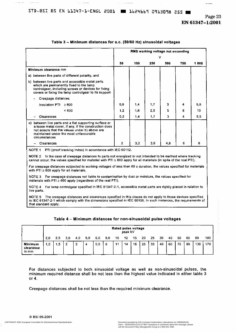
Creepage distances and clearances shall be not less than the values given in tables 3 and 4, as appropriate, unless otherwise specified in clause 14.
The contribution to the creepage distance of any groove less than I mm wide shall be limited to its width.
Any air gap of less than I mm shall be ignored in computing the total air path.
NOTE 1 Creepage distances are distances in air, measured along the external surface of the insulating material.
NOTE 2 Distances between ballast windings are not measured because they are checked with the endurance test. This applies also to distances between taps.
A metal enclosure shall have an insulating lining in accordance with IEC 60598-1 if, in the absence of such a lining, the creepage distance or clearance between the live parts and the enclosure would be smaller than the value prescribed in the relevant tables.
Lamp controlgear, where the components are so encapsulated in a self-hardening compound bonded to the relevant surfaces that no clearances exist, are not checked.
Printed circuit boards are exempt from the requirements of this clause because they are tested according to clause 14.
O BSI 05-2001
COPYRIGHT 2003; European Committee for Electrotechnical Standardization
Document provided by IHS Licensee=Underwriters Laboratories Inc /5909636100,User=, 06/20/2003 02:01:07 MDT Questions or comments about this message: pleasecall the Document Policy Management Group at 1-800-451-1584.
--```,`,,`,```,,`````,,,`,,,`,,-`-`,,`,,`,`,,`---
STD-ES1 ES EN b3347-3-ENGL 2003 I1624669 0733098 255 Page 23
EN 61347-1:2001
- Clearances
Table 3 - Minimum distances for a.c. (SOI60 Hr) sinusoidal voltages
2 3 2
Minimum clearance mm
a) between live parts of different polarity, and
b) between live parts and accessible metal parts which are permanently fixed to the lamp controlgear, including screws or devices for fixing covers or fixing the lamp controlgear to its support
- Creepage distances
Minimum clearance in mm
RUS working voltage not exceedlng
v
1,0 1,5 2 3 4 5 3 8 1 1 14 18 25 33 40 60 75 90 130 170
50 150
Ï Insulation PTI 2 600
< 600
- Clearances 0 2
c) between live parts and a flat supporting surface or a loose metal cover, if any, if the construction does not ensure that the values under b) above are maintained under the most unfavourable circumstances
250 500 -
3
5
3 -
4 3
750
6
1 O00
5 3
10
535
8
NOTE 2 cannot occur, the values specified for material with PTI t 600 apply for all materials (in spite of the real PTI).
For creepage distances subjected to working voltages of less than 60 s duration, the values specified for materials with PTI 2 600 apply for all materials.
NOTE 3 materials with PTI 2 600 apply (regardless of the real PTI).
NOTE 4 live parts.
NOTE 5 in IEC 61347-2-1 which comply with the dimensions specified in IEC 60155. In such instances, the requirements of that standard aDDIY.
In the case of creepage distances to parts not energized or not intended to be earthed where tracking
For creepage distances not liable to contamination by dust or moisture, the values specified for
For lamp controlgear specified in IEC 61347-2-1, accessible metal parts are rigidly placed in relation to
The creepage distances and clearances specified in this clause do not apply to those devices specified
Table 4 - Minimum distances for non-sinusoidal pulse voltages
Rated pulse voltage peak kV
2,O 2,5 3,O 4,O 5,O 6,O 8,0 10 12 15 20 25 30 40 50 60 80 100
For distances subjected to both sinusoidal voltage as well as non-sinusoidal pulses, the minimum required distance shall be not less than the highest value indicated in either table 3 or 4.
Creepage distances shall be not less than the required minimum clearance.
Q BSI 05-2001 COPYRIGHT 2003; European Committee for Electrotechnical Standardization
Document provided by IHS Licensee=Underwriters Laboratories Inc /5909636100,User=, 06/20/2003 02:01:07 MDT Questions or comments about this message: pleasecall the Document Policy Management Group at 1-800-451-1584.
--```,`,,`,```,,`````,,,`,,,`,,-`-`,,`,,`,`,,`---
STDmBSI BS EN 61347-1-ENGL 2 O O L 1624669 0933099 191 Page 24 EN 61347-1:2001
17 Screws, current-carrying parts and connections
Screws, current-carrying parts and mechanical connections, the failure of which might cause the lamp controlgear to become unsafe, shall withstand the mechanical stresses occurring in normal use.
Compliance is checked by inspection and the tests of 4.11 and 4.12 of section 4 of IEC 60598-1.
18 Resistance to heat, fire and tracking
18.1 against electric shock shall be sufficiently resistant to heat.
Parts of insulating material either retaining live parts in position or providing protection
For materiais other than ceramic, compliance is checked by subjecting the parts to the ball- pressure test according to section 13 of IEC 60598-1.
18.2 External parts of insulating material providing protection against electric shock and parts of insulating material retaining live parts in position shall be sufficiently resistant to flame and ignition/fire.
For materials other than ceramic, compliance is checked by the tests of 18.3 or 18.4, as appropriate.
Printed circuit boards are not tested as above, but in accordance with 4.3 of IEC 60249-1.
18.3 External parts of insulating material providing protection against electric shock shall be subjected for 30 s to the glow-wire test in accordance with IEC 60695-2-1, subject to the following details:
- the test sample shall be one specimen;
- the test specimen shall be a complete lamp controlgear; - the temperature of the tip of the glow-wire shall be 650 OC;
- any (self-sustaining) flame or glowing of the specimen shall extinguish within 30 s of removal of the glow wire and any flaming drops shall not ignite a piece of tissue paper, as specified in 6.86 of IS0 4046, spread out horizontally 200 mm f 5 mm below the test specimen.
Parts of insulating material retaining live parts in position shall be subjected to the 18.4 needle-flame test in accordance with IEC 60695-2-2, subject to the following details:
- the test sample shall be one specimen;
- the test specimen shall be a complete lamp controlgear. If it is necessary to take away parts of the lamp controlgear to perform the test, care shall be taken to ensure that the test conditions are not significantly different from those occurring in normal use;
- the test flame is applied to the centre of the surface to be tested;
O BSI 05-2001
COPYRIGHT 2003; European Committee for Electrotechnical Standardization
Document provided by IHS Licensee=Underwriters Laboratories Inc /5909636100,User=, 06/20/2003 02:01:07 MDT Questions or comments about this message: pleasecall the Document Policy Management Group at 1-800-451-1584.
--```,`,,`,```,,`````,,,`,,,`,,-`-`,,`,,`,`,,`---
STD-BSI B S EN bL347-1-ENGL 2OOL = Lb24669 0913LOO 733 Page 25
EN 61347-1:2001
- the duration of application is I O s; - any self-sustaining flame shall extinguish within 30 s of removal of the gas flame, and any
flaming drops shall not ignite a piece of tissue paper as specified in 6.86 of I S 0 4046, spread out horizontally 200 mm f 5 mm below the test specimen.
18.5 Lamp controlgear intended for building into luminaires other than ordinary, independent lamp controlgear, and lamp controlgear having insulation subject to starting voltages with a peak value higher than 1 500 V shall be resistant to tracking.
For materials other than ceramic, compliance is checked by subjecting the parts to the tracking test according to section 13 of IEC 60598-1.
19 Resistance to corrosion
Ferrous parts, the rusting of which might cause the lamp controlgear to become unsafe, shall be adequately protected against rusting.
Compliance is checked by the test of 4.78.7 of section 4 of IEC 60598-7.
Protection by varnish is deemed to be adequate for the outer surfaces.
O BSI 05-2001
COPYRIGHT 2003; European Committee for Electrotechnical Standardization
Document provided by IHS Licensee=Underwriters Laboratories Inc /5909636100,User=, 06/20/2003 02:01:07 MDT Questions or comments about this message: pleasecall the Document Policy Management Group at 1-800-451-1584.
--```,`,,`,```,,`````,,,`,,,`,,-`-`,,`,,`,`,,`---
STD*BSI BS EN b1347-1-ENGL 2001 Lb24bb9 0933LOL b7T Page 26 EN 61347-1:2001
300
250
200
190
180
1 70
160
150
1 O0 15 I 30
Test period in days
40 , D
IEC 5/36/2000
NOTE These curves are for information only and illustrate equation (2) using a constant S of 4 500 (see annex E).
Figure 1 - Relation between winding temperature and endurance tes t duration
O BSI 05-2001
~~
COPYRIGHT 2003; European Committee for Electrotechnical Standardization
Document provided by IHS Licensee=Underwriters Laboratories Inc /5909636100,User=, 06/20/2003 02:01:07 MDT Questions or comments about this message: pleasecall the Document Policy Management Group at 1-800-451-1584.
--```,`,,`,```,,`````,,,`,,,`,,-`-`,,`,,`,`,,`---

STDaBSI BS EN bL347-L-ENGL 2003 m 3b24bb9 0933302 506 m Page 27
EN 61347-1:2001
10 9
7
6
5
a
4
3
E E
m UI
P 0,9
.E 0,8 0,7
.-
0.3
Peak value of the operating voltage V
IEC 587/2000
Figure 2 - Creepage distances between conductors on printed boards not conductively connected to the supply mains
O BSI 05-2001
COPYRIGHT 2003; European Committee for Electrotechnical Standardization
Document provided by IHS Licensee=Underwriters Laboratories Inc /5909636100,User=, 06/20/2003 02:01:07 MDT Questions or comments about this message: pleasecall the Document Policy Management Group at 1-800-451-1584.
--```,`,,`,```,,`````,,,`,,,`,,-`-`,,`,,`,`,,`---

STD-ES1 BS EN b1347-1-ENGL 2001 Lb24bb7 07L3L03 442 Page 28 EN 61347-1:2001
Annex A (normative)
Test to establish whether a conductive part is a live part which may cause an electric shock
In order to determine whether a conductive part is a live part which may cause an electric shock, the lamp controlgear is operated at rated voltage and nominal supply frequency, and the following tests are conducted.
A.1 measured.
The part concerned is a live part if a current of more than 0,7 mA (peak) or 2 mA d.c. is
For frequencies above 1 kHz, the limit of 0,7 mA (peak) is multiplied by the value of the frequency in kilohertz, but the result shall not exceed 70 mA (peak).
The current flowing between the part concerned and earth is measured.
Compliance is checked by measurement in accordance with figure 4 and 7. I of / E C 60990.
A.2 The voltage between the part concerned and any accessible part is measured, the measuring circuit having a non-inductive resistance of 50 kR. The part concerned is a live part if a voltage of more than 34 V (peak) is measured.
For the above test, one pole of the test supply shall be at earth potential.
O BSI 05-2001
~
COPYRIGHT 2003; European Committee for Electrotechnical Standardization
Document provided by IHS Licensee=Underwriters Laboratories Inc /5909636100,User=, 06/20/2003 02:01:07 MDT Questions or comments about this message: pleasecall the Document Policy Management Group at 1-800-451-1584.
--```,`,,`,```,,`````,,,`,,,`,,-`-`,,`,,`,`,,`---
STD-BSI BS EN bL347-1-ENGL 2OOL m 1624669 09L31OV 389 m Page 29
EN 61347-1:2001
Annex B (normative)
Particular requirements for thermally protected lamp controlgear
B.l Introductory remark
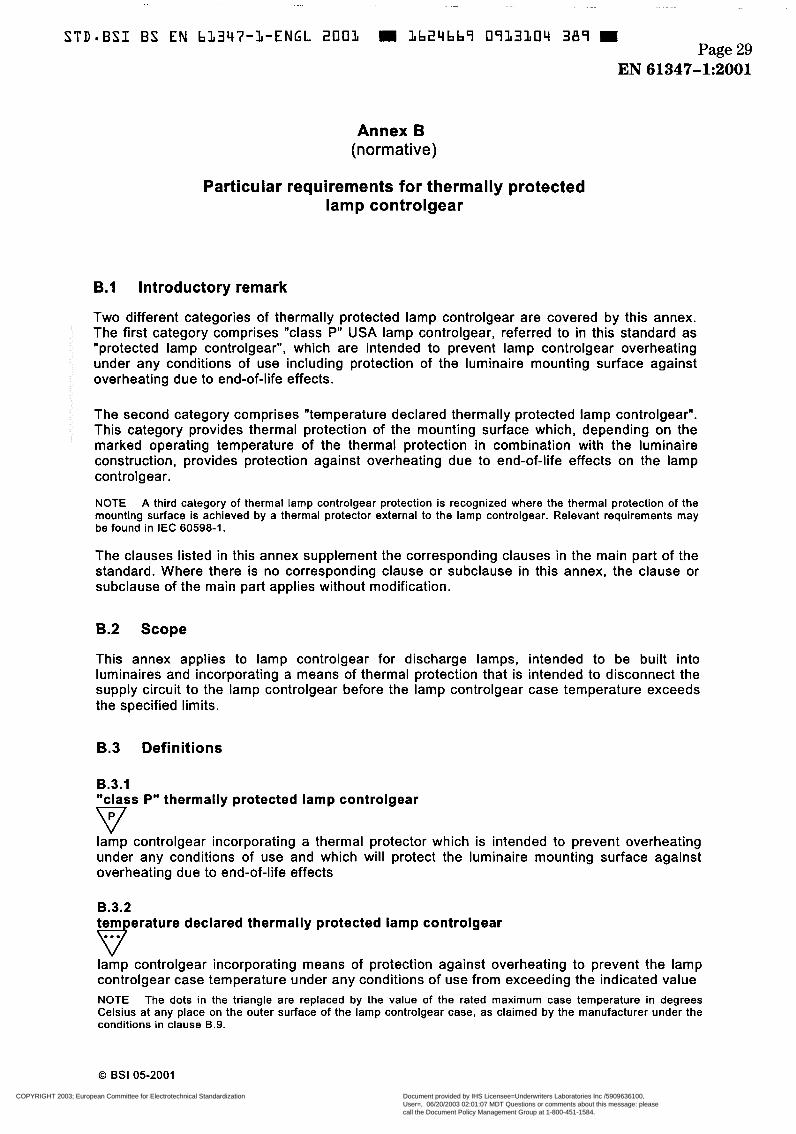
Two different categories of thermally protected lamp controlgear are covered by this annex. The first category comprises "class P" USA lamp controlgear, referred to in this standard as "protected lamp controlgear", which are intended to prevent lamp controlgear overheating under any conditions of use including protection of the luminaire mounting surface against overheating due to end-of-life effects.
The second category comprises "temperature declared thermally protected lamp controlgear". This category provides thermal protection of the mounting surface which, depending on the marked operating temperature of the thermal protection in combination with the luminaire construction, provides protection against overheating due to end-of-life effects on the lamp controlgear.
NOTE A third category of thermal lamp controlgear protection is recognized where the thermal protection of the mounting surface is achieved by a thermal protector external to the lamp controlgear. Relevant requirements may be found in IEC 60598-1.
The clauses listed in this annex supplement the corresponding clauses in the main part of the standard. Where there is no corresponding clause or subclause in this annex, the clause or subclause of the main part applies without modification.
B.2 Scope
This annex applies to lamp controlgear for discharge lamps, intended to be built into luminaires and incorporating a means of thermal protection that is intended to disconnect the supply circuit to the lamp controlgear before the lamp controlgear case temperature exceeds the specified limits.
B.3 Definitions
B.3.1 "class P" thermally protected lamp controlgear
lamp controlgear incorporating a thermal protector which is intended to prevent overheating under any conditions of use and which will protect the luminaire mounting surface against overheating due to end-of-life effects
v B.3.2 tem erature declared thermally protected lamp controlgear
lamp controlgear incorporating means of protection against overheating to prevent the lamp controlgear case temperature under any conditions of use from exceeding the indicated value NOTE The dots in the triangle are replaced by the value of the rated maximum case temperature in degrees Celsius at any place on the outer surface of the lamp controlgear case, as claimed by the manufacturer under the conditions in clause B.9.
O BSI 05-2001
COPYRIGHT 2003; European Committee for Electrotechnical Standardization
Document provided by IHS Licensee=Underwriters Laboratories Inc /5909636100,User=, 06/20/2003 02:01:07 MDT Questions or comments about this message: pleasecall the Document Policy Management Group at 1-800-451-1584.
--```,`,,`,```,,`````,,,`,,,`,,-`-`,,`,,`,`,,`---