lancaster's water and sewerage systems part two: …
TRANSCRIPT
LANCASTER'S WATER AND SEWERAGE SYSTEMS PART TWO: THE PIPES
Keith Horsfield
LANCASTER'S WATER AND SEWERAGE IN THE EARLY NINETEENTH CENTURY
At the start of the nineteenth century Lancaster's streets had central surface drains, but starting in 1812 sub-surface drains were installed; these were also known as sewers. Rectangular in section and made of rough-cast stone, they measured about 18 by 12 and were suitable only for the drainage of rain water. All except those in Bridge Lane drained into the mill race (Lancaster Gazette 4th July 1812, 3). Householders saw their chance and connected their cess-pools, water closets and house drains to them, as did the slaughter houses. Inevitably, solid materials got stuck in them and they turned into linear cess-pits. As liquid leaked out and soaked into the ground, the wells were yet further polluted (LRL MS 154, 79). The smell in Lancaster, especially in summertime, was quite appalling. Even a member of the Police Commissioners (see above), Mr. Satterthwaite, stated that a stranger to the town was impressed with it being one of the nastiest and filthiest places in existence. It is difficult these days for us to imagine how awful it must have been!
EARLY EFFORTS TO OBTAIN SEWERAGE AND WATER SYSTEMS
Edwin Chadwick (see above p26) had realised the problems with stone drains and he recommended in general that sewers should be of small diameter to encourage flow through them, round or oval in section, and made of glazed earthenware or metal; bends should be gradual curves rather than right-angled. A good supply of water would be needed to flush them through; the sewage itself would be disposed of on the land (LG 8th May 1852, 5).
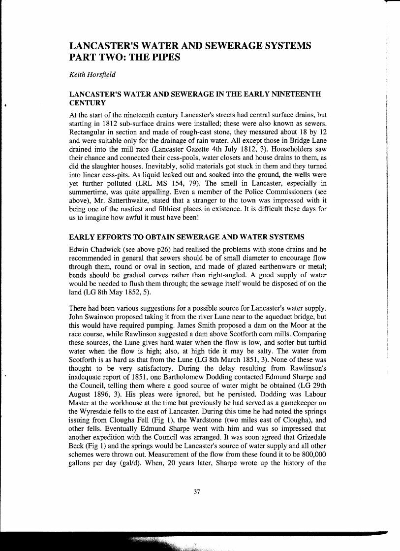
There had been various suggestions for a possible source for Lancaster's water supply. John Swainson proposed taking it from the river Lune near to the aqueduct bridge, but this would have required pumping. James Smith proposed a dam on the Moor at the race course, while Rawlinson suggested a dam above Scotforth corn mills. Comparing these sources, the Lune gives hard water when the flow is low, and softer but turbid water when the flow is high; also, at high tide it may be salty. The water from Scotforth is as hard as that from the Lune (LG 8th March 1851, 3). None of these was thought to be very satisfactory. During the delay resulting from Rawlinson's inadequate report of 1851, one Bartholomew Dodding contacted Edmund Sharpe and the Council, telling them where a good source of water might be obtained (LG 29th August 1896, 3). His pleas were ignored, but he persisted. Dodding was Labour Master at the workhouse at the time but previously he had served as a gamekeeper on the Wyresdale fells to the east of Lancaster. During this time he had noted the springs issuing from Clougha Fell (Fig 1), the Wardstone (two miles east of Clougha), and other fells. Eventually Edmund Sharpe went with him and was so impressed that another expedition with the Council was arranged. It was soon agreed that Grizedale Beck (Fig 1) and the springs would be Lancaster's source of water supply and all other schemes were thrown out. Measurement of the flow from these found it to be 800,000 gallons per day (gal/d). When, 20 years later, Sharpe wrote up the history of the
37
discovery of this source of water, he attributed the find all to himself (Sharpe 1876, 40) making no mention of Dodding's contribution. Bartholomew Dodding is the longforgotten and unsung hero of Lancaster's excellent early water supply.
\ N
LWTW =Lancaster Water Treatment Works
~ DsmasGiH Reaervmr
Figure 1. Sketch map of the geography of Lancaster's waterworks, showing most of the features mentioned in the text, but excluding the intake on the River Lune at Caton
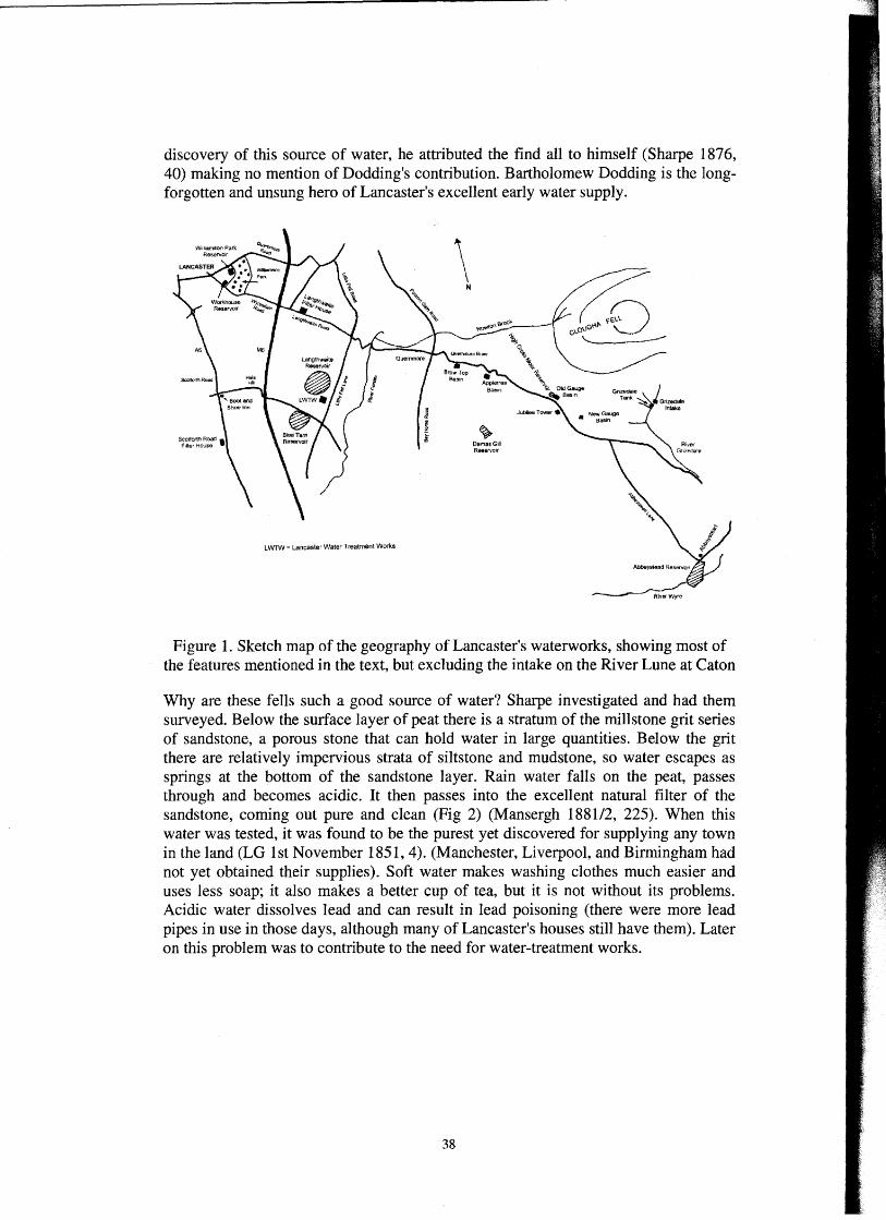
Why are these fells such a good source of water? Sharpe investigated and had them surveyed. Below the surface layer of peat there is a stratum of the millstone grit series of sandstone, a porous stone that can hold water in large quantities. Below the grit there are relatively impervious strata of siltstone and mudstone, so water escapes as springs at the bottom of the sandstone layer. Rain water falls on the peat, passes through and becomes acidic. It then passes into the excellent natural filter of the sandstone, coming out pure and clean (Fig 2) (Mansergh 1881/2, 225). When this water was tested, it was found to be the purest yet discovered for supplying any town in the land (LG lst November 1851, 4). (Manchester, Liverpool, and Birmingham had not yet obtained their supplies). Soft water makes washing clothes much easier and uses less soap; it also makes a better cup of tea, but it is not without its problems. Acidic water dissolves lead and can result in lead poisoning (there were more lead pipes in use in those days, although many of Lancaster's houses still have them). Later on this problem was to contribute to the need for water-treatment works.
38
s
IMPERVIOUS SHALES AND MUDSTONES
N
Figure 2. Simplified diagram of a vertical geological section through Clougha Fell, showing the origins of the springs (from Mansergh 1881/2, 255)
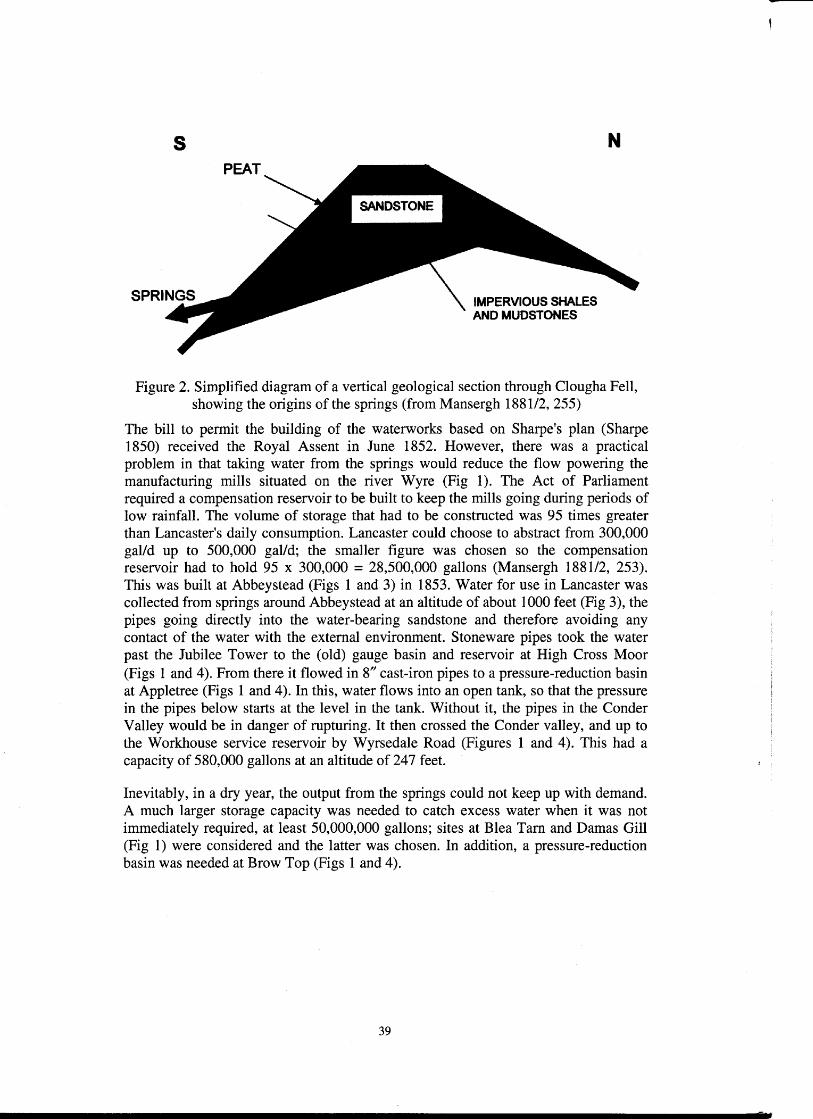
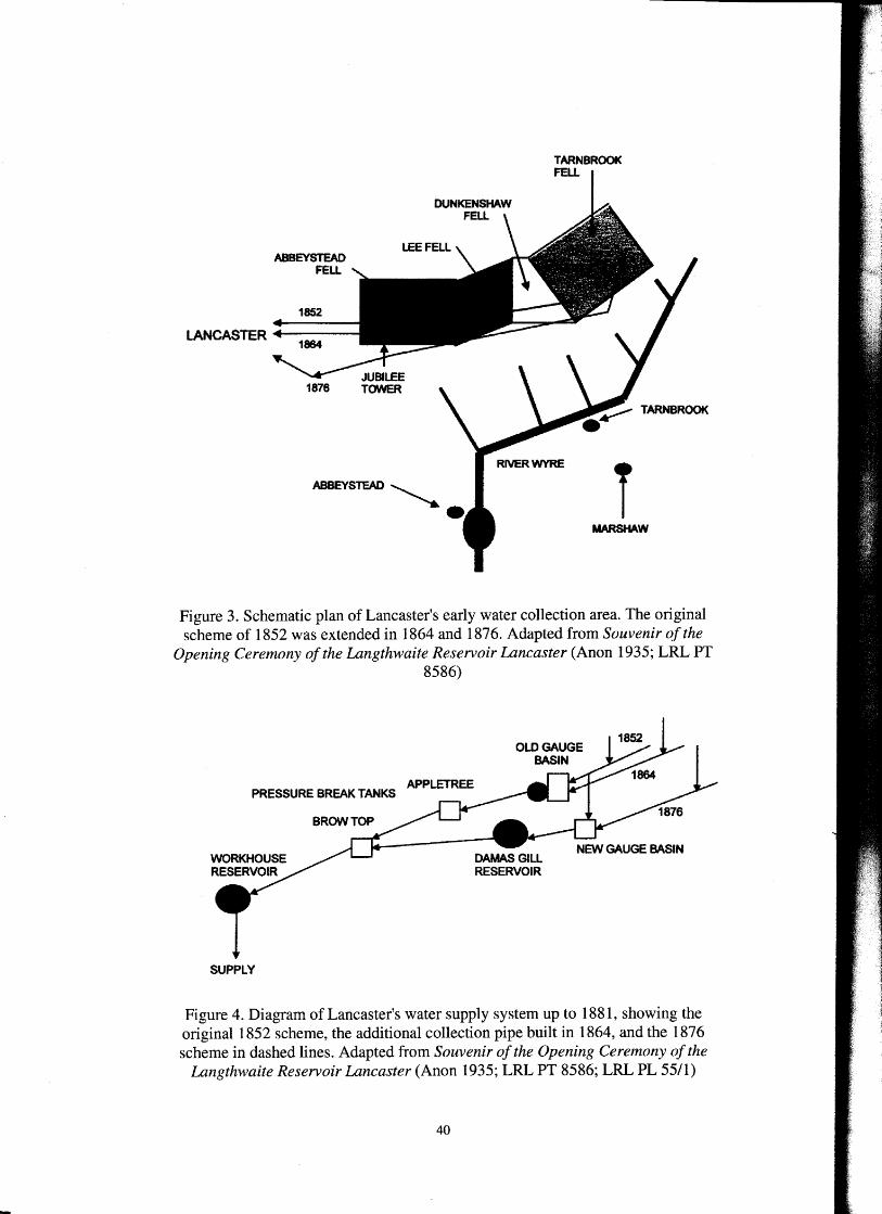
The bill to permit the building of the waterworks based on Sharpe's plan (Sharpe 1850) received the Royal Assent in June 1852. However, there was a practical problem in that taking water from the springs would reduce the flow powering the manufacturing mills situated on the river Wyre (Fig 1). The Act of Parliament required a compensation reservoir to be built to keep the mills going during periods of low rainfall. The volume of storage that had to be constructed was 95 times greater than Lancaster's daily consumption. Lancaster could choose to abstract from 300,000 gal/d up to 500,000 gal/d; the smaller figure was chosen so the compensation reservoir had to hold 95 x 300,000 = 28,500,000 gallons (Mansergh 1881/2, 253). This was built at Abbeystead (Figs 1 and 3) in 1853. Water for use in Lancaster was collected from springs around Abbeystead at an altitude of about 1000 feet (Fig 3), the pipes going directly into the water-bearing sandstone and therefore avoiding any contact of the water with the external environment. Stoneware pipes took the water past the Jubilee Tower to the (old) gauge basin and reservoir at High Cross Moor (Figs 1 and 4). From there it flowed in 8" cast-iron pipes to a pressure-reduction basin at Appletree (Figs 1 and 4). In this, water flows into an open tank, so that the pressure in the pipes below starts at the level in the tank. Without it, the pipes in the Conder Valley would be in danger of rupturing. It then crossed the Conder valley, and up to the Workhouse service reservoir by Wyrsedale Road (Figures 1 and 4). This had a capacity of 580,000 gallons at an altitude of 247 feet.
Inevitably, in a dry year, the output from the springs could not keep up with demand. A much larger storage capacity was needed to catch excess water when it was not immediately required, at least 50,000,000 gallons; sites at Blea Tarn and Damas Gill (Fig 1) were considered and the latter was chosen. In addition, a pressure-reduction basin was needed at Brow Top (Figs 1and4).
39
TARNBROOK FELL
LEE FELL
1852
LANCASTER ._ __ _ 1864
ABBEYSTEAD ~
• T MARSHAW
Figure 3. Schematic plan of Lancaster's early water collection area. The original scheme of 1852 was extended in 1864 and 1876. Adapted from Souvenir of the
Opening Ceremony of the Langthwaite Reservoir Lancaster (Anon 1935; LRL PT 8586)
APPLETREE PRESSURE BREAK TANKS
SUPPLY
Figure 4. Diagram of Lancaster's water supply system up to 1881, showing the original 1852 scheme, the additional collection pipe built in 1864, and the 1876 scheme in dashed lines. Adapted from Souvenir of the Opening Ceremony of the
Langthwaite Reservoir Lancaster (Anon 1935; LRL PT 8586; LRL PL 55/1)
40
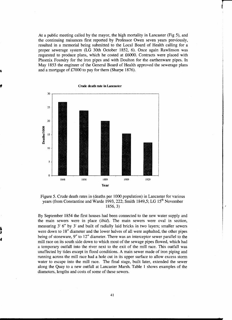
At a public meeting called by the mayor, the high mortality in Lancaster (Fig 5), and the continuing nuisances first reported by Professor Owen seven years previously, resulted in a memorial being submitted to the Local Board of Health calling for a proper sewerage system (LG 30th October 1852, 6). Once again Rawlinson was requested to produce plans, which he costed at £6000. Contracts were placed with Phoenix Foundry for the iron pipes and with Doulton for the earthenware pipes. In May 1853 the engineer of the General Board of Health approved the sewerage plans and a mortgage of £7000 to pay for them (Sharpe 1876).
Crude death rate in Lancaster
1848 1856 1889 1909 1929
Year
Figure 5. Crude death rates in (deaths per 1000 population) in Lancaster for various years (from Constantine and Warde 1993, 222; Smith 1849,5; LG 15th November
1856, 3)
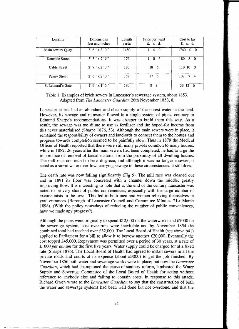
By September 1854 the first houses had been connected to the new water supply and the main sewers were in place (ibid). The main sewers were oval in section, measuring 3' 6" by 3' and built of radially laid bricks in two layers; smaller sewers were down to 18" diameter and the lower halves of all were asphalted, the other pipes being of stoneware, 9" to 12" diameter. There was an interceptor sewer parallel to the mill race on its south side down to which most of the sewage pipes flowed, which had a temporary outfall into the river next to the exit of the mill race. This outfall was unaffected by tides except in flood conditions. A main sewer made of iron piping and running across the mill race had a hole cut in its upper surface to allow excess storm water to escape into the mill race. The final stage, built later, extended the sewer along the Quay to a new outfall at Lancaster Marsh. Table 1 shows examples of the diameters, lengths and costs of some of these sewers.
41
Locality Dimensions Length Price per yard Cost to lay feet and inches yards £. s. d. £. s. d.
Main sewers Quay 3' 6" x 3' O" 1450 1 4 0 1740 0 0
Damside Street 3' 3" x 2' 9" 176 1 0 6 180 8 0
Cable Street 2' 9" x 2' 3" 120 18 5 110 10 0
Penny Street 2' 6" x 2' O" 152 17 5 132 7 4
St Leonard's Gate 1' 9" x 1' 6" 130 8 3 53 12 6
Table 1. Examples of brick sewers in Lancaster's sewerage system, about 1853. Adapted from The Lancaster Guardian 26th November 1853, 8.
Lancaster at last had an abundant and cheap supply of the purest water in the land. However, its sewage and rainwater flowed in a single system of pipes, contrary to Edmund Sharpe's recommendations. It was cheaper to build them this way. As a result, the sewage was too dilute to use as fertiliser and the hoped-for income from this never materialised (Sharpe 1876, 53). Although the main sewers were in place, it remained the responsibility of owners and landlords to connect them to the houses and progress towards completion seemed to be painfully slow. Thus in 1879 the Medical Officer of Health reported that there were still many privies common to many houses, while in 1882, 26 years after the main sewers had been completed, he had to urge the importance of removal of faecal material from the proximity of all dwelling houses. The mill race continued to be a disgrace, and although it was no longer a sewer, it acted as a storm water overflow, carrying sewage in these circumstances. It still does.
The death rate was now falling significantly (Fig 5). The mill race was cleaned out and in 1891 its floor was concreted with a channel down the middle, greatly improving flow. It is interesting to note that at the end of the century Lancaster was noted to be very short of public conveniences, especially with the large number of excursionists in the town. This led to both men and women relieving themselves in yard entrances (Borough of Lancaster Council and Committee Minutes 2lst March 1898). (With the policy nowadays of reducing the number of public conveniences, have we made any progress?).
Although the plans were originally to spend £12,000 on the waterworks and £7000 on the sewerage system, cost over-runs were inevitable and by November 1854 the combined total had reached over £32,000. The Local Board of Health (see above p41) applied to Parliament for a bill to allow it to borrow another £20,000. Eventually the cost topped £45,000. Repayment was permitted over a period of 30 years, at a rate of £1000 per annum for the first five years. Water supply could be charged for at a fixed rate (Sharpe 1876). The Local Board of Health had agreed to install sewers in all the private roads and courts at its expense (about £9000) to get the job finished. By November 1856 both water and sewerage works were in place; but now the Lancaster Guardian, which had championed the cause of sanitary reform, lambasted the Water Supply and Sewerage Committee of the Local Board of Health for acting without reference to anybody else and failing to contain costs. In response to this attack, Richard Owen wrote to the Lancaster Guardian to say that the construction of both the water and sewerage systems had been well done but not overdone, and that the
42
' I
t ,
cost per head had been less than that of most other towns (LG 16th December 1854, 3). It would prove to be well worthwhile. At this stage the waterworks belonged to the Local Board of Health, so a proposal was made for the Council to purchase them.
FURTHER DEVELOPMENT OF THE WATER SUPPLY
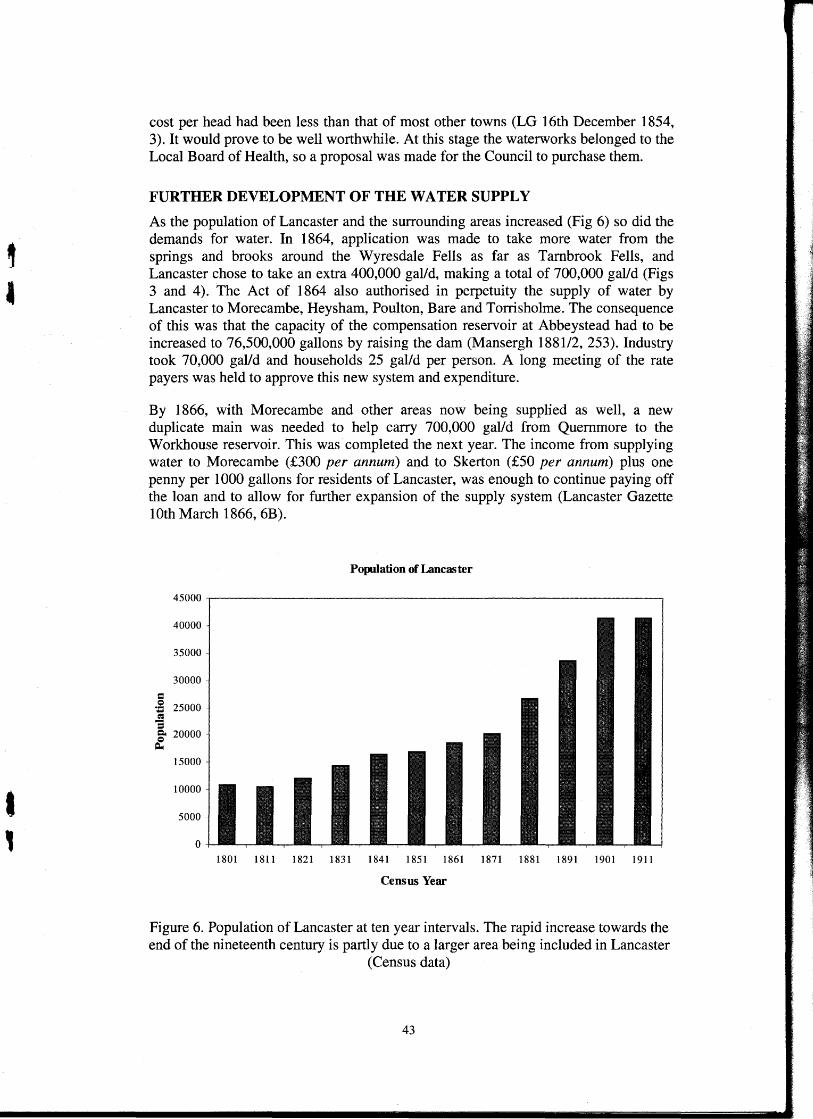
As the population of Lancaster and the surrounding areas increased (Fig 6) so did the demands for water. In 1864, application was made to take more water from the springs and brooks around the Wyresdale Fells as far as Tambrook Fells, and Lancaster chose to take an extra 400,000 gal/d, making a total of 700,000 gal/d (Figs 3 and 4). The Act of 1864 also authorised in perpetuity the supply of water by Lancaster to Morecambe, Heysham, Poulton, Bare and Torrisholme. The consequence of this was that the capacity of the compensation reservoir at Abbeystead had to be increased to 76,500,000 gallons by raising the dam (Mansergh 1881/2, 253). Industry took 70,000 gal/d and households 25 gal/d per person. A long meeting of the rate payers was held to approve this new system and expenditure.
By 1866, with Morecambe and other areas now being supplied as well, a new duplicate main was needed to help carry 700,000 gal/d from Quemmore to the Workhouse reservoir. This was completed the next year. The income from supplying water to Morecambe (£300 per annum) and to Skerton (£50 per annum) plus one penny per 1000 gallons for residents of Lancaster, was enough to continue paying off the loan and to allow for further expansion of the supply system (Lancaster Gazette lOth March 1866, 6B).
40000
35000
30000
= ~ 25000 = = §' 20000
Q.
15000
10000
5000
0
Population of Lancaster
1801 1811 1821 1831 1841 1851 1861 1871 1881 1891 1901 1911
Census Year
Figure 6. Population of Lancaster at ten year intervals. The rapid increase towards the end of the nineteenth century is partly due to a larger area being included in Lancaster
(Census data)
43
Once again, the supply off the fells had to be increased. An Act of 1874 permitted Lancaster to take up to two million gal/d from a catchment area of 3400 acres, subject to enlarging Abbeystead compensation reservoir to hold 185 million gallons. Permission was also given to construct a reservoir at Damas Gill (Figs 1 and 4). This time the dam at Abbeystead could not be raised any further so a new masonry dam (one of the first in the country) was constructed immediately downstream of, and next to, the existing dam. A further pipeline all the way to the Tambrook Fells was laid in 1876 to carry the extra supply of water. This required a new gauge basin to measure flow. It was situated about half a mile south of the Jubilee Tower and connected to a new pressure break basin at Brow Top (Figs 1 and 4). This supply was later connected to Damas Gill reservoir.
Lancaster clearly had a considerable civic pride in its waterworks. Each year the civic dignitaries and any others who could make it went on an inspection tour of pipes and reservoirs. In 1875, 70 people set off from the Kings Arms Hotel in carriages, taking picnics and hampers of wine. The demand for transport was so great that all spare carriages and horses in Lancaster had to be utilised (LG 21st August 1875, 4). A great time was had by all!
One of the mill owners near Abbeystead, a Mr Garnett, feeling that his right to water supply had been infringed, chose to sue the Council for a large sum of money. However, he did not do very well, being awarded one tenth of his claim plus half of what he had been offered. His award totalled £3500, a very good deal for the Council compared with the cost of building more reservoir storage for him (LG 11 th December 1880, 5).
Storage facilities were increased in 1891 with the building of Damas Gill reservoir, which, while being built across Damas Gill, was not allowed to take water from it, the stream being diverted round each side of the reservoir (Anon 1935). This had a capacity of 35 million gallons. In 1894 it was decided to construct a reservoir at Blea Tam (Fig 1), on Scotforth Heights overlooking Lancaster (Anon 1935). It was to be fed by pipelines from the gathering grounds or from the Damas Gill reservoir that is situated at a higher level. Some 200,000 cubic yards of peat were dug out, giving the reservoir a capacity of 120 million gallons, compared with 20 million for Damas Gill; it was completed in 1901. At first the water came unfiltered from the springs, but because of the desire to store water collected in time of flood, water was taken in addition from streams. Because of the resulting discolouration, coupled with algal growth becoming a problem on Blea Tam, a filtration plant was built at Burrow Beck Bridge, Scotforth (Fig 1) in 1913 (Anon 1935) and this was enlarged at intervals, in 1920, 1935, 1963 and 1971. Enclosed sand filters were employed, which were cleaned at intervals by reversing the flow of water through them, the dirty water then being discharged into the sewers. From Scotforth the clean water flowed up to the Wyresdale Road service reservoir under the hydrostatic pressure from the higher Blea Tam. (A service reservoir contains clean treated water and is covered over to keep it clean. Water passes from here to the customer). The Wyresdale Road reservoir had previously been known as the Workhouse reservoir (Figs 1 and 7) owing to its proximity to this institution. The Grammar School now occupies the site of the Workhouse.
In 1918 an Act was passed permitting Lancaster to take as much water as it needed, say twice as much as then currently being used, provided that there was an adequate
44
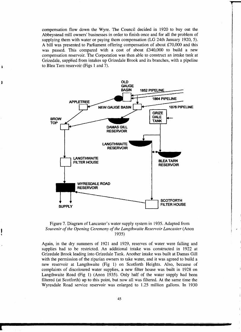
compensation flow down the Wyre. The Council decided in 1920 to buy out the Abbeystead mill owners' businesses in order to finish once and for all the problem of supplying them with water or paying them compensation (LG 24th January 1920, 5). A bill was presented to Parliament offering compensation of about £70,000 and this was passed. This compared with a cost of about £340,000 to build a new compensation reservoir. The Corporation was then able to construct an intake tank at Grizedale, supplied from intakes up Grizedale Brook and its branches, with a pipeline to Blea Tam reservoir (Figs 1 and 7).
BROW TOP
LANGTHWAITE FILTER HOUSE
OLD GAUGE
BASIN1.__~185~2~P~IP~E=ll=N=E::::::==
LANGTHWAITE RESERVOIR
GRIZE DALE TANK
BLEA TARN RESERVOIR
___....__ SCOTFORTH FILTER HOUSE
Figure 7. Diagram of Lancaster's water supply system in 1935. Adapted from Souvenir of the Opening Ceremony of the Langthwaite Reservoir Lancaster (Anon
1935)
Again, in the dry summers of 1921 and 1929, reserves of water were falling and supplies had to be restricted. An additional intake was constructed in 1922 at Grizedale Brook leading into Grizedale Tank. Another intake was built at Damas Gill with the permission of the riparian owners to take water, and it was agreed to build a new reservoir at Langthwaite (Fig 1) on Scotforth Heights. Also, because of complaints of discoloured water supplies, a new filter house was built in 1928 on Langthwaite Road (Fig 1) (Anon 1935). Only half of the water supply had been filtered (at Scotforth) up to this point, but now all was filtered. At the same time the Wyresdale Road service reservoir was enlarged to 1.25 million gallons. In 1930
45
, I
L
Lancaster Corporation's waterworks was supplying the Boroughs of Lancaster, Morecambe and Heysham, Bare, Torrisholme, Bolton-le-Sands, and the Rural Districts of Lancaster and Lunesdale. The population in this area was normally about 80,000, but was considerably increased in summer due to the influx of visitors. With dry summers and the inexorable increase in Lancaster's population, water supply had to be restricted and the need for another reservoir was becoming urgent. A site was chosen on Scotforth Heights between Blea Tam and Langthwaite Road, the reservoir taking the name of Langthwaite. This had been foreseen and an Act of 1918 had permitted the compulsory purchase of land provided that it was done within five years of the end of the war, which it was. Work started in 1931 under the management of Mansergh and Sons, consulting engineers. There was another agenda in the construction of Langthwaite reservoir. This was a time of high unemployment and it gave the opportunity to employ up to 260 men recruited by the Lancaster Employment Exchange. None lived on site; they were carried there each day from Lancaster by motor omnibus. The reservoir was opened in 1934 and had a capacity of 190 million gallons; it was supplied by a branch of the Grizedale-Blea Tam pipe (Anon 1935). Figure 7 shows a diagram of Lancaster's waterworks as they were in 1935, the Workhouse reservoir now being known as the Wyresdale Road service reservoir.
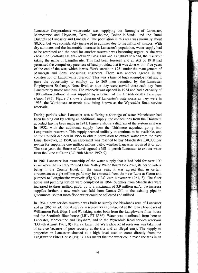
During periods when Lancaster was suffering a shortage of water Manchester had been helping out by selling an additional supply, the connections from the Thirlmere aqueduct having been made in 1941. Figure 8 shows a diagram of the system as it was in 1952, with the additional supply from the Thirlmere aqueduct going into Langthwaite reservoir. This supply seemed unlikely to continue to be available, and so the Council decided in 1956 to obtain permission to extract water from the river Lune. However, in 1958, an agreement was reached to pay Manchester £30,000 per annum for supplying one million gallons daily, whether Lancaster required it or not. The next year, the House of Lords agreed a bill to permit Lancaster to extract water from the Lune at Caton (LG 20th March 1959, 9).
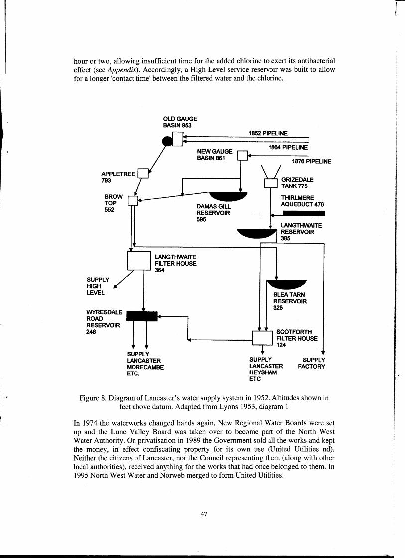
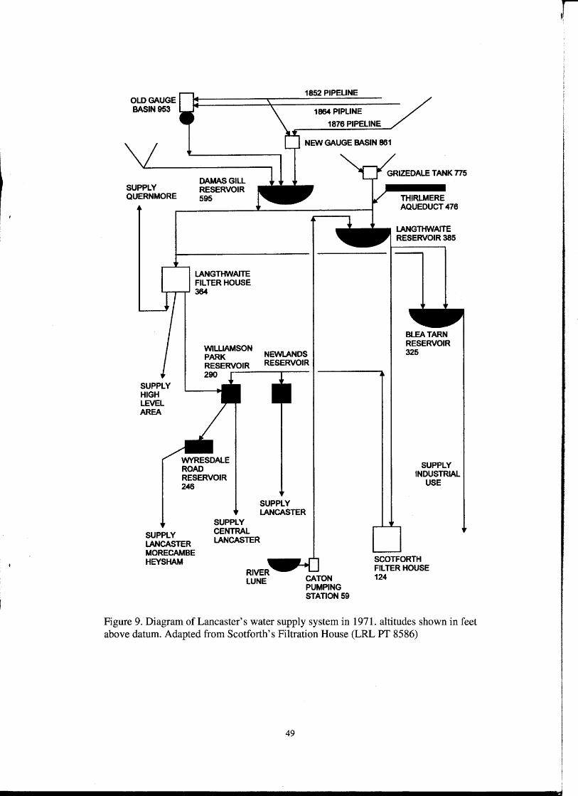
In 1961 Lancaster lost ownership of the water supply that it had held for over 100 years when the recently formed Lune Valley Water Board took over, its headquarters being in the County Hotel. In the same year, it was agreed that in certain circumstances eight million gal/d may be extracted from the river Lune at Caton and pumped to Langthwaite reservoir (Fig 9) ( LG 24th November 1961, 8). The filter house and pumping station were completed in 1964. Supplies from Manchester were increased to three million gal/d, up to a maximum of 3.9 million gal/d. To increase supplies further, a new main was laid from Damas Gill to the existing pipe in Quemmore, so that more flood water could be collected and utilised.
In 1964 a new service reservoir was built to supply the Newlands area of Lancaster and in 1965 an additional service reservoir was constructed at the lower boundary of Williamson Park (Figs 1 and 9), taking water both from the Langthwaite filter house and the Scotforth filter house (LRL PT 8586). Water was distributed from here to Lancaster, Morecambe and Heysham, and to the Wyresdale Road service reservoir (LG 4th August 1961, 9) (Fig 9). Later, the Wyresdale Road reservoir was taken out of service because of poor security at the site and an illegal entry. The supply to properties in Lancaster situated at a high level used to come directly from the Langthwaite Filter House (Fig 8). This meant that the water could reach the taps in an
46
-- -------=-=='--===--"""""""iiiiiiiiiiiiii .............. iiiiiiiiiiiiiiiiiiiiiiiiiiiiiiiiiiii-------
hour or two, allowing insufficient time for the added chlorine to exert its antibacterial effect (see Appendix). Accordingly, a High Level service reservoir was built to allow for a longer 'contact time' between the filtered water and the chlorine.
OLD GAUGE BASIN953
NEW GAUGE BASIN 861
APPLETREE 793
BROW TOP 552
SUPPLY HIGH LEVEL
WYRESDALE ROAD RESERVOIR 246
LANGTHWAITE FILTER HOUSE __ __, 384
SUPPLY LANCASTER MORECAMBE ETC.
1852 PIPELINE
1864 PIPELINE
1876 PIPELINE
THIRLMERE AQUEDUCT 476
BLEA TARN RESERVOIR 325
........z-...z.- SCOTFORTH FILTER HOUSE
--~ 124
SUPPLY LANCASTER HEY SHAM ETC
SUPPLY FACTORY
Figure 8. Diagram of Lancaster's water supply system in 1952. Altitudes shown in feet above datum. Adapted from Lyons 1953, diagram 1
In 197 4 the waterworks changed hands again. New Regional Water Boards were set up and the Lune Valley Board was taken over to become part of the North West Water Authority. On privatisation in 1989 the Government sold all the works and kept the money, in effect confiscating property for its own use (United Utilities nd). Neither the citizens of Lancaster, nor the Council representing them (along with other local authorities), received anything for the works that had once belonged to them. In 1995 North West Water and Norweb merged to form United Utilities.
47
-'
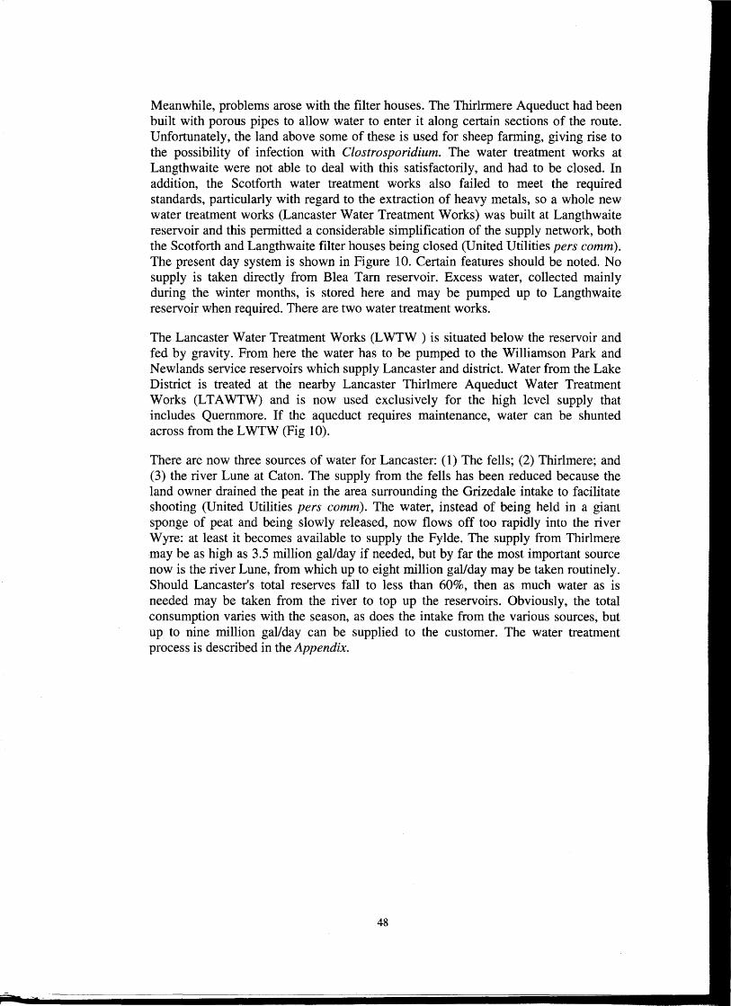
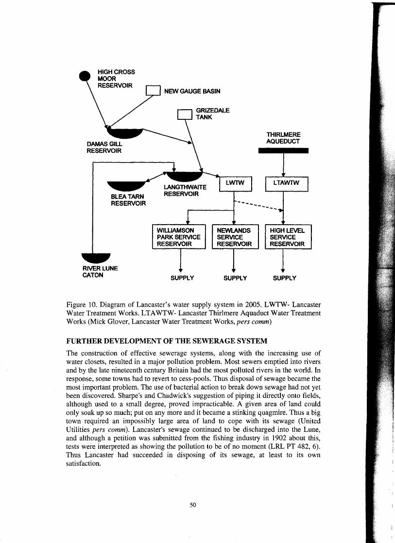
Meanwhile, problems arose with the filter houses. The Thirlrmere Aqueduct had been built with porous pipes to allow water to enter it along certain sections of the route. Unfortunately, the land above some of these is used for sheep farming, giving rise to the possibility of infection with Clostrosporidium. The water treatment works at Langthwaite were not able to deal with this satisfactorily, and had to be closed. In addition, the Scotforth water treatment works also failed to meet the required standards, particularly with regard to the extraction of heavy metals, so a whole new water treatment works (Lancaster Water Treatment Works) was built at Langthwaite reservoir and this permitted a considerable simplification of the supply network, both the Scotforth and Langthwaite filter houses being closed (United Utilities pers comm). The present day system is shown in Figure 10. Certain features should be noted. No supply is taken directly from Blea Tam reservoir. Excess water, collected mainly during the winter months, is stored here and may be pumped up to Langthwaite reservoir when required. There are two water treatment works.
The Lancaster Water Treatment Works (LWTW) is situated below the reservoir and fed by gravity. From here the water has to be pumped to the Williamson Park and Newlands service reservoirs which supply Lancaster and district. Water from the Lake District is treated at the nearby Lancaster Thirlmere Aqueduct Water Treatment Works (LTA WTW) and is now used exclusively for the high level supply that includes Quemmore. If the aqueduct requires maintenance, water can be shunted across from the LWTW (Fig 10).
There are now three sources of water for Lancaster: (1) The fells; (2) Thirlmere; and (3) the river Lune at Caton. The supply from the fells has been reduced because the land owner drained the peat in the area surrounding the Grizedale intake to facilitate shooting (United Utilities pers comm). The water, instead of being held in a giant sponge of peat and being slowly released, now flows off too rapidly into the river Wyre: at least it becomes available to supply the Fylde. The supply from Thirlmere may be as high as 3.5 million gal/day if needed, but by far the most important source now is the river Lune, from which up to eight million gal/day may be taken routinely. Should Lancaster's total reserves fall to less than 60%, then as much water as is needed may be taken from the river to top up the reservoirs. Obviously, the total consumption varies with the season, as does the intake from the various sources, but up to nine million gal/day can be supplied to the customer. The water treatment process is described in the Appendix.
48
OLD GAUGE BASIN953
SUPPLY QUERNMORE
DAMAS GILL RESERVOIR 595
LANGTHWAITE FILTER HOUSE
1852 PIPELINE
1864 PIPLINE
1876 PIPELINE
NEW GAUGE BASIN 861
THIRLMERE AQUEDUCT 476
LANGTHWAITE RESERVOIR 385
....,_...--.... 364
SUPPLY HIGH LEVEL AREA
SUPPLY LANCASTER MORECAMBE HEYSHAM
WILLIAMSON PARK RESERVOIR
NEWLAN OS RESERVOIR
290 ..--~~~-r-~-
SUPPLY LANCASTER
SUPPLY CENTRAL LANCASTER
CATON PUMPING STATION59
BLEA TARN RESERVOIR 325
SUPPLY INDUSTRIAL
USE
SCOTFORTH FILTER HOUSE 124
Figure 9. Diagram of Lancaster's water supply system in 1971. altitudes shown in feet above datum. Adapted from Scotforth' s Filtration House (LRL PT 8586)
49
HIGH CROSS MOOR RESERVOIR
BLEA TARN RESERVOIR
RIVER LUNE CATON
NEW GAUGE BASIN
WILLIAMSON PARK SERVICE RESERVOIR
SUPPLY
LWfW
------
NEWLAN OS SERVICE RESERVOIR
SUPPLY
THIRLMERE AQUEDUCT
LTAWTW
---
HIGH LEVEL SERVICE RESERVOIR
SUPPLY
Figure 10. Diagram of Lancaster's water supply system in 2005. LWTW- Lancaster Water Treatment Works. LT A WTW- Lancaster Thirlmere Aquaduct Water Treatment Works (Mick Glover, Lancaster Water Treatment Works, pers comm)
FURTHER DEVELOPMENT OF THE SEWERAGE SYSTEM
The construction of effective sewerage systems, along with the increasing use of water closets, resulted in a major pollution problem. Most sewers emptied into rivers and by the late nineteenth century Britain had the most polluted rivers in the world. In response, some towns had to revert to cess-pools. Thus disposal of sewage became the most important problem. The use of bacterial action to break down sewage had not yet been discovered. Sharpe's and Chadwick's suggestion of piping it directly onto fields, although used to a small degree, proved impracticable. A given area of land could only soak up so much; put on any more and it became a stinking quagmire. Thus a big town required an impossibly large area of land to cope with its sewage (United Utilities pers comm). Lancaster's sewage continued to be discharged into the Lune, and although a petition was submitted from the fishing industry in 1902 about this, tests were interpreted as showing the pollution to be of no moment (LRL PT 482, 6). Thus Lancaster had succeeded in disposing of its sewage, at least to its own satisfaction.
50

Up until 1930 Lancaster had been pouring its raw sewage into the river Lune from six outflows on the south side of the river. That year the Ministry of Agriculture and Fisheries submitted a report on the condition of the river Lune to the Highways Committee, following the issuing of a summons against Lancaster Corporation for polluting the river by the Lune Board of Conservators. As a result an engineer was engaged to prepare a report and outline of a suitable scheme for dealing with the problem. In 1934 the project was started. Its objectives were to divert all of the six outflows on the south side of the river to a point at Stodday, where the flow of the river was sufficient to dilute the effluent satisfactorily (Anon 1933). The works were designed to deal with up to 3.25 million gal/d (see Figure 11 for a plan of the main features of the system).
The Riverside pumping station at Skerton Bridge Yard was constructed to deal with the effluent from the Riverside Works, Caton Road, and the Bulk estate, which flowed down the Victorian gravity brick sewer. Previously all of this was discharged into the Lune at Skerton Bridge and at high tides the backflow used to boil out of the manholes (United Utilities pers comm). The effluent was diverted under the railway line to the pumping station and a storm water overflow provided. From here the effluent was pumped uphill in cast-iron and steel pipes lined with bitumen. It went along Parliament Street, Cable Street, Damside Street, St George's Quay, across the LMS railway Glasson Dock branch, Willow Lane Housing Estate, and the Marsh to near Brookholme Farm.
The sewer from the Willow Lane Housing Estate, that previously discharged into the Lune near the New Quay, was joined by another sewer that also discharged into the Lune, one of the outflows being converted into a storm water overflow. The effluent was pumped uphill from the Lune Mills pumping station, in a pipe laid parallel to the one from the Riverside pumping station, to near Brookholme Farm. From here the sewage flowed downhill to the works at Stodday. This is the situation at the present time.
At Stodday a detritus tank was constructed in which the solids settled out, to be removed later by a mechanical digging machine. At the outlet from this tank a screen removed most of the remaining solids that did not settle. From there the liquid passed to one of four tidal storage tanks with a combined capacity of 1.5 million gallons (United Utilities pers comm). These held the liquid while the tide came in, and it was released into the estuary on the ebb tide. The exit of the outflow pipe was below the low water mark. The previous outflow pipe that discharged onto the foreshore was converted into a storm water overflow. Most of the construction was carried out by Direct Labour, the majority of the men being transferred from working on the Langthwaite reservoir. At the period of peak construction, 150 men were employed.
51
-- -- -------- -

RIVER LUNE
BROOKHOLME FARM
~CATON ~WORKS
BRICK +---SEWER
RIVERSIDE PUMPING STATION
STORM WATER OVERFLOWS --
SETILINGAND FILTERING TANK
STODDAY
--- TIDAL STORAGE TANKS
Figure 11. Diagram of Lancaster's sewerage system in 1933. Adapted from Official Opening of the Sewerage Scheme (Anon 1933)
Development of the Stodday works was at first very slow. In 1955 a further 12 tidal storage tanks were constructed and then little happened for the next 20 years. However, it became obvious that a proper treatment works was needed, and in the late 1970s and early 1980s inlet screening works, grit removal, primary treatment and sludge digestion facilities were constructed. Following a European Union Waste Water Directive, secondary treatment works were added in 1999 that can reduce the suspended solids by over 90% and the next year the sludge treatment plant was extended (United Utilities pers comm). This not only deals with Lancaster's sludge but also that carried in by road from the surrounding areas. The wastewater treatment process is described in the Appendix.
52

THE MILL RACE
In 1998 repairs to the mill race were needed at North Road, as there was a serious danger of it collapsing. When the sewers were burdened by a heavy load of storm water, raw sewage overflowed into the mill race and out into the river Lune. In order to lessen this nuisance it was decided, while work was going on in the mill race, to take the opportunity to build new storm water overflows. Five of these were constructed, at Bulk Road, Wood Street, Cable Street, lower Damside Street and Rosemary Lane, the latter not being on the mill race (United Utilities pers comm). In these overflows, vertical overlapping baffles hold up the passage of floating solids while allowing the passage of liquid. Ideally, each overflow should have a filter, but there was insufficient room to build them. Instead, a filter station was built on Pye's old car park, at the lower end of the mill race. This stops solids of greater than 6 mm passing, which is an improvement but a long way from perfect. During rain storms sewage still gets into the river Lune, but on the other hand at these times there is a greater flow of water to dilute it, thus reducing the nuisance.
The sewers that the Victorians built under Lancaster are still there to this day. Although some have been repaired and the system added to, the original sewers still survive and function, unseen and usually unnoticed, serving the people of Lancaster.
ACKNOWLEDGEMENTS
I wish to thank John Nelson, Mick Glover and Phil Smith of United Utilities for their generous help, both for historical information and for explaining how the systems work.
REFERENCES
LG = Lancaster Guardian
LRL = Lancaster Reference Library
MS = Manuscript in LRL
PL = Plan in LRL
PT = Pamphlet in LRL
Primary Sources
Anon, 1933 Official Opening of the Sewerage Scheme, City of Lancaster
Anon, 1935 Souvenir of the Opening Ceremony of the Langthwaite Reservoir, Lancaster
Lancaster Gazette 4th July 1812
Lancaster Gazette 1 Oth March 1866
United Utilities nd Lancaster Wastewater Treatment works,
LG 8th March 1851
53
LG lst November 1851
LG 8th May 1852
LG 30th October 1852
LG 26th November 1853
LG 16th December 1854
LG 15th November 1856
LG 21st August 1875
LG 11 th December 1880
LG 29th August 1896
LG 24th January 1920
LG 20th March 1959
LG 4th August 1961
LG 24th November 1961
LRL MS 154, 79
LRL PT 482, River Lune Pollution, 6
LRL PL 55/18 Lancaster Corporation Waterworks 1881
LRL PT 500, Smith, J, 1849 Report to the Local Board of Health, 5
LRL Scotforth Filtration House 1971, PT 8586
LRL Sharpe, E, 1850 A Proposal for Supplying the Town of Lancaster with Water and for Improving its Sewerage, PT 462
LRL Borough of Lancaster Council and Committee Minutes, Sanitary Committee,
21st March 1898
Lyons, L, 1933 City of Lancaster Report on the Water Undertaking
Mansergh, J, 1881/2 Lancaster Waterworks Extension, Minutes of Proceedings of the
Institute of Civil Engineers
Secondary Sources
Constantine, S, and Warde, A, 1993 Challenge and Change in the 20th Century, in A White, (ed), A History of Lancaster 1193-1193, Keele, 199-243
54
Sharpe, E, 1876 A History of the Progress of Sanitary Reform in the Town of Lancaster from 1845 to 1875; and an account of its water supplies, Lancaster
White, A ( ed), 1993 A History of Lancaster 1193-1993
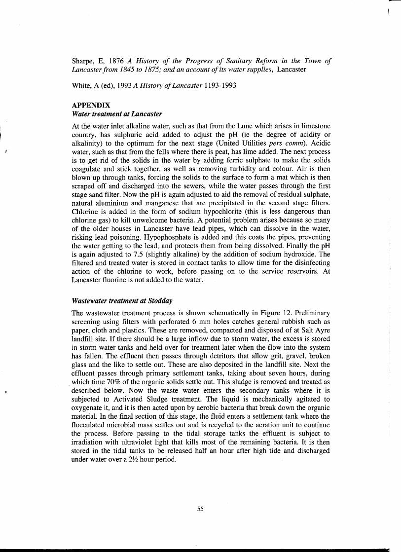
APPENDIX Water treatment at Lancaster
At the water inlet alkaline water, such as that from the Lune which arises in limestone country, has sulphuric acid added to adjust the pH (ie the degree of acidity or alkalinity) to the optimum for the next stage (United Utilities pers comm). Acidic water, such as that from the fells where there is peat, has lime added. The next process is to get rid of the solids in the water by adding ferric sulphate to make the solids coagulate and stick together, as well as removing turbidity and colour. Air is then blown up through tanks, forcing the solids to the surface to form a mat which is then scraped off and discharged into the sewers, while the water passes through the first stage sand filter. Now the pH is again adjusted to aid the removal of residual sulphate, natural aluminium and manganese that are precipitated in the second stage filters. Chlorine is added in the form of sodium hypochlorite (this is less dangerous than chlorine gas) to kill unwelcome bacteria. A potential problem arises because so many of the older houses in Lancaster have lead pipes, which can dissolve in the water, risking lead poisoning. Hypophosphate is added and this coats the pipes, preventing the water getting to the lead, and protects them from being dissolved. Finally the pH is again adjusted to 7.5 (slightly alkaline) by the addition of sodium hydroxide. The filtered and treated water is stored in contact tanks to allow time for the disinfecting action of the chlorine to work, before passing on to the service reservoirs. At Lancaster fluorine is not added to the water.
Wastewater treatment at Stodday
The wastewater treatment process is shown schematically in Figure 12. Preliminary screening using filters with perforated 6 mm holes catches general rubbish such as paper, cloth and plastics. These are removed, compacted and disposed of at Salt Ayre landfill site. If there should be a large inflow due to storm water, the excess is stored in storm water tanks and held over for treatment later when the flow into the system has fallen. The effluent then passes through detritors that allow grit, gravel, broken glass and the like to settle out. These are also deposited in the landfill site. Next the effluent passes through primary settlement tanks, taking about seven hours, during which time 70% of the organic solids settle out. This sludge is removed and treated as described below. Now the waste water enters the secondary tanks where it is subjected to Activated Sludge treatment. The liquid is mechanically agitated to oxygenate it, and it is then acted upon by aerobic bacteria that break down the organic material. In the final section of this stage, the fluid enters a settlement tank where the flocculated microbial mass settles out and is recycled to the aeration unit to continue the process. Before passing to the tidal storage tanks the effluent is subject to irradiation with ultraviolet light that kills most of the remaining bacteria. It is then stored in the tidal tanks to be released half an hour after high tide and discharged under water over a 2¥2 hour period.
55
-

Inlet
Smm screens
Storm overflow
Primary treatment
Secondary treatment
Settlement tanks
Ultra violet light
Tidal tanks
River Lune
Land fill
Land fill
Storage
Recycled sludge
Sludge treatment
Methane
Fertiliser on farmland
Figure 12. Schematic of the function of Lancaster's wastewater treatment facility at Stodday in 2005. Adapted from Lancaster Wastewater treatment Works (United
Utilities nd)
The sludge removed from the primary tanks contains 3% solids. The volume is reduced by half to give 6% solids and passes to primary digesters for at least 13 days, kept at 30-35°C to aid bacterial action, and then to secondary digesters for 14 days, in both of which anaerobic bacterial action breaks it down to a material that can be used as a fertiliser. The process generates methane that is stored and used to drive an electrical generator and to warm water to maintain the temperature of the bacterial process at 30-35°C. At present (October 2005) some of the methane goes to waste, but when a further generator is installed the works will be self-sufficient in energy and also be able to supply excess electricity to the national grid. The treated sludge is stored and then taken by road to farms where it used as fertiliser at no cost to the farmer.
56