lanmark-of demarcation box - nexans...slide the heat shrink protection tubes onto the fibres and...
TRANSCRIPT

LANmark-OF Demarcation Box
PRODUCT INSTALLATION GUIDE
June 2019 v1.01

LANmark-OF Demarcation Box • Installation Guide • Page 2
LANmark-OF Demarcation Box
PRODUCT INSTALLATION GUIDE
Product References
Part Number Description
N521.621 LANmark-OF Demarcation Box 12 Core Multimode White
N521.622 LANmark-OF Demarcation Box 12 Core Singlemode White
Document information
Release June 2019 Published by Nexans Cabling Solutions Contact address Alsembergsesteenweg 2, b3
1501 Buizingen Belgium
Phone +32 2 363 38 00 Fax +32 2 365 09 99 Website www.nexans.com/ncs E-mail [email protected]
Important Notice
The information contained in this document has been carefully checked and is assumed to be entirely
correct and reliable at the time of publishing. However, Nexans Cabling Solutions reserves the right to
make such changes to its products or its documentation as it deems necessary, in order to make
improvements. Nexans Cabling Solutions rejects all responsibility for the use made of its products or
of its documentation. In this document, no mention is made of rights with respect to trademarks or
tradenames which may attach to certain words or signs. The absence of such mention, however, in
no way implies that there is no protection. © 2019 Nexans Cabling Solutions

LANmark-OF Demarcation Box • Installation Guide • Page 3
General
Installation is to be performed by qualified
service personnel.
The installation of the LANmark-OF
Demarcation Box must be carried out with
care and precision.
Prior to installation, preparation work should be
carried out on a clean and level work-surface.
Each demarcation box comes preloaded with 6
duplex LC adaptors and is supplied with:
• 1 loop ring
• 2 nuts
All other ancillaries (e.g. splice trays) must be purchased separately. The product part numbers are mentioned where applicable in the following.
Configuration
Installation with Micro-bundle cable:
This is selected to create networks based on
FTTO ring cabling topology (see LANactive
section of the NCS website):
• a bundle is extracted from the cable
and is terminated in the Demarcation
Box

LANmark-OF Demarcation Box • Installation Guide • Page 4
Phase 1 - Preparation of the Demarcation Box
The cover is fastened with 4 screws,
2 on the left and 2 on the right side.
Remove the cover to get access to the plastic bag containing the accessories. Install the loop ring in the appropriate fixing point.

LANmark-OF Demarcation Box • Installation Guide • Page 5
Phase 2 - Installation with Micro-bundle cable
Micro-bundle cables, having extractable features, are selected to create networks based on FTTO ring cabling topology (see LANactive section of the NCS website).
Note: extraction of Micro-Bundle is possible over a length up to 2 m
1. Description of the extraction process
1 bundle of 12 fibres has to be extracted from the cable and be terminated in the in the Demarcation Box. First of all, the jacket of the cable has to be opened and a piece of 30 to 40 millimeters removed, at maximum 2 meters away from the box (or in between 2 boxes if the same bundle will be terminated in 2 consecutive boxes). The OGCL stripping tool (NCS part number: N890.131) shall be used to perform this task to ensure that the bundles and the fibres will not be affected by this process. The bundle to be terminated in the Demarcation Box will then be cut.
Using the same OGCL stripping tool the cable jacket will also need to be opened at the location where the Demarcation Box will be installed. A piece of the jacket having the length needed to fully expose the bundle inside the box has to be removed. The appropriate bundle will be extracted from the cable. The fibres will then be spliced on LC pigtails and these will be connected to the LC adaptors of the Demarcation Box. The exposed bundles located between 2 boxes will be covered with a cable protection box. N890.170 LANmark-OF Mini Rootfloor 5mm
LANmark-OF Demarcation Box • Installation Guide • Page 6
Phase 2 - Installation with Micro-bundle cable
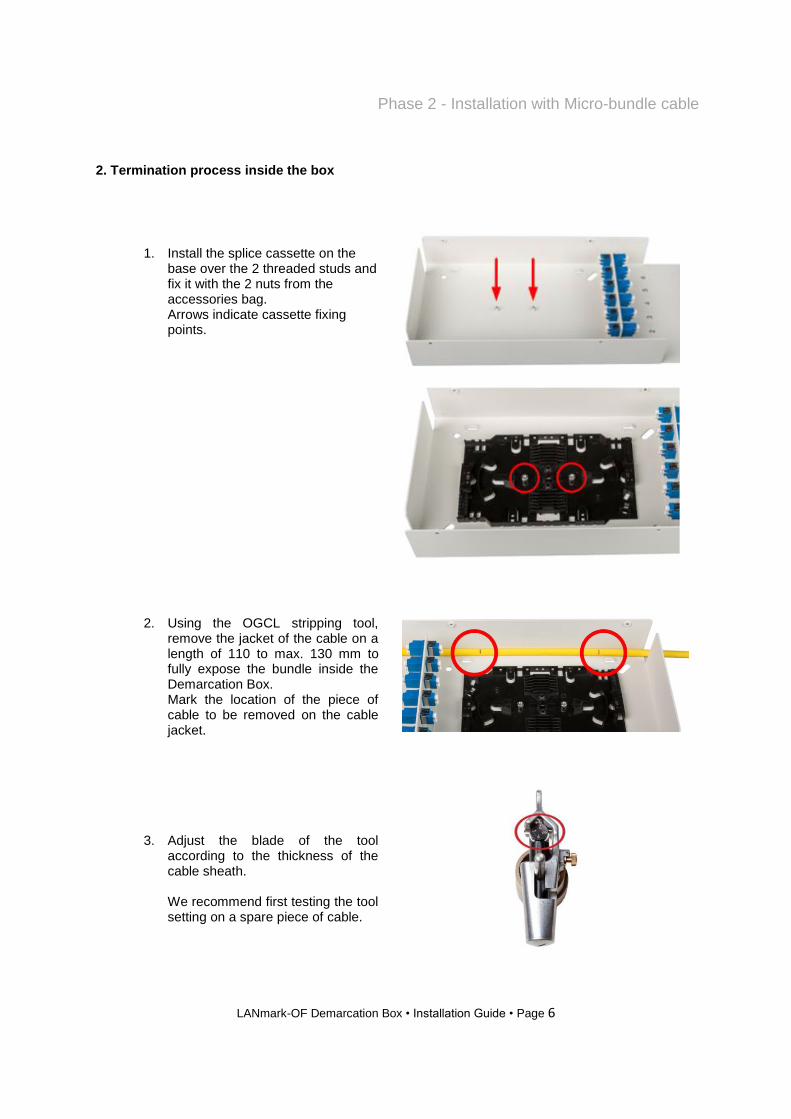
2. Termination process inside the box
1. Install the splice cassette on the base over the 2 threaded studs and fix it with the 2 nuts from the accessories bag. Arrows indicate cassette fixing points.
2. Using the OGCL stripping tool, remove the jacket of the cable on a length of 110 to max. 130 mm to fully expose the bundle inside the Demarcation Box. Mark the location of the piece of cable to be removed on the cable jacket.
3. Adjust the blade of the tool according to the thickness of the cable sheath. We recommend first testing the tool setting on a spare piece of cable.

LANmark-OF Demarcation Box • Installation Guide • Page 7
Phase 2 - Installation with Micro-bundle cable
4. Set the tool in longitudinal cutting mode using D (pull + turn).
5. Cut the jacket longitudinally between the 2 marks using the part of the tool dedicated to this operation. First, the blade has to be set into the right position to adjust the penetration into the jacket and then locked using E.

LANmark-OF Demarcation Box • Installation Guide • Page 8
Phase 2 - Installation with Micro-bundle cable
6. Set the tool in the circular cutting mode using D (pull + turn).
7. Place the tool on the cable with the blade located at the end of the longitudinal cut (on the first mark) and rotate the tool around the cable to cut the jacket.
8. Repeat the process to cut the jacket at the other end of the longitudinal cut (on the second mark).

LANmark-OF Demarcation Box • Installation Guide • Page 9
Phase 2 - Installation with Micro-bundle cable
9. Gently remove the jacket.
10. Install the cable in the Demarcation Box and fix it on both sides using tie-wraps (not provided). Do not over-tighten the tie-wraps.

LANmark-OF Demarcation Box • Installation Guide • Page 10
Phase 2 - Installation with Micro-bundle cable
11. Pull the appropriate bundle out of the cable.
12. Guide the bundle to the splice tray leaving at least one loop of slack bundle around the tray and cut off the surplus length leaving at least 2 loops of slack fibres in the splice tray. Strip the bundle using the appropriate tool (Multi-Wire stripper 821 – Ripley / Miller or equivalent).
13. Clean the fibres with an appropriate
and suitable solvent to remove the gel. Fix the end of the remaining bundle on the splice tray (A) by means of tie-wraps (not provided). Do not over-tighten the tie-wraps on the bundle / tube as they are not used for strain relief but to keep the bundle in the right position. The fibres from the pigtails should make 2 loops inside the splice cassette.

LANmark-OF Demarcation Box • Installation Guide • Page 11
Phase 2 - Installation with Micro-bundle cable
For Tight Buffer pigtails measure the length of the 900µ buffer needed on the splice tray and fix the fibre in the comb (B) of the splice tray. For Maxistrip pigtails, measure the length of 250µm buffered fibre needed on the splice tray, strip the 900µ buffer and fix the end of 900µ buffer in the comb (B) of the splice tray.
14. Slide the heat shrink protection
tubes onto the fibres and joint them by fusion splicing with pigtails following the correct colour sequence. The “Recommendations to maintain duplex OF channel polarity” technical paper, which is available from our NCS website (under the File Library), should be considered when choosing the colour order (see Annex B). When all pigtails are spliced and installed, close the splice cassette with the cover (N890.097).
Important note
The inspection and appropriate cleaning of all the optical fibre connectors (pigtails,
patch cords etc) prior to mating is a critical process that needs to be followed at all
times.
Latest applications have stringent link loss requirements and in order to ensure that the
required performances levels are achieved during commissioning and operation, the
cleanliness of all fibre interfaces needs to be maintained.
See Annex A

LANmark-OF Demarcation Box • Installation Guide • Page 12
Phase 3 - Finalisation of the installation
The Demarcation Box can now be gently closed.
Fix the cover with the 4 screws.
Label the ports and the cable conform to the site labeling scheme.

LANmark-OF Demarcation Box • Installation Guide • Page 13
Phase 3 - Finalisation of the installation
The Demarcation Box installation is now
completed.
Spare / slack cable should then be appropriately secured depending on the installation requirements of the site.
Testing must be carried out in accordance with
client requirements and Nexans requirements
for warranty submission. Patch cords can now be installed.
To connect patch cords, open the front lid and
connect the cords.
It is recommended to guide the cords through
the loop ring.
On completion the installation must be handed
over to the customer with all dust caps fitted to
unpatched adaptors.
Any dust caps that have been removed must be
stored appropriately for potential re-use.
Optical Power / Safety levels warning labelling,
and security procedures must have been
implemented on completion of the installation.
If needed, the front lid can be secured by
means of a lock (not provided).

LANmark-OF Demarcation Box • Installation Guide • Page 14
Annex A
IMPORTANT NOTE – INSPECTION, CLEANING & TESTING
The inspection and appropriate cleaning of all the optical fibre connectors (pigtails, patch cords
etc) prior to mating is a critical process that needs to be followed at all times.
Latest applications have stringent link loss requirements and in order to ensure that the required
performances levels are achieved during commissioning and operation, the cleanliness of all fibre
interfaces needs to be maintained.
The Nexans OF connector Inspection, Cleaning & Testing general guidelines can be downloaded from the Nexans website.
In addition, there is also a General Installation guide (for both copper and fibre) which includes further information.
Please note: The Nexans warranty may be invalidated if the cables have not been properly stored
or handled according to Nexans Cabling Solutions (NCS) requirements. When logged into the
NCS site, all these documents and also others relating to design and installation testing etc.
can be found here
Note: if the Nexans 25 year system warranty is required, testing and submission of results for
certification is a mandatory requirement.
Testing has to be performed according to the Nexans OF field testing procedure which is
available from our website.
LANmark-OF Demarcation Box • Installation Guide • Page 15
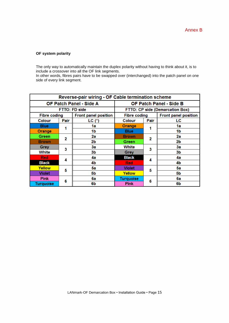
Annex B
OF system polarity
The only way to automatically maintain the duplex polarity without having to think about it, is to include a crossover into all the OF link segments. In other words, fibres pairs have to be swapped over (interchanged) into the patch panel on one side of every link segment.

LANmark-OF Demarcation Box • Installation Guide • Page 16
Disclaimer
This document is a guideline only. International and local procedures and safety standards must
be observed and followed at all times.
Nexans Cabling Systems will not be held liable for any damage or injury to personnel, equipment
or business directly or indirectly as a result of using this document in part or in whole.
The practices contained herein are designed as a guide for use by persons having the required
technical skill at their own discretion and risk. The recommended practices are based on average
conditions. Nexans does not guarantee any favourable results or assume any liability in connection
with this document.
Nexans does not assume any responsibility for the accuracy or completeness of this document.
The user should review the information to ensure conformity to the current applicable codes and
regulations and to the project requirements.
Nexans reserves the right to change the technical specifications at any time without notice.
Edition 26.06.2019
Copyright © Nexans 2019
All data subject to change
without prior notice.