lansocket 1500 product guide
TRANSCRIPT
Extollo Communications LANSocket 1500 Product Guide

2
The information contained within this document is confidential and cannot be reproduced without the approval of Extollo Communications.
Table of Contents Glossary of Terms ...................................................................................................................................... 3
Introduction .................................................................................................................................................. 4
HomePlug AV and AV2 Network Overview ............................................................................................ 5
Product Overview ....................................................................................................................................... 6
Ethernet Packet Flow ................................................................................................................................. 7
Multiple-In Multiple-Out with Beamforming ............................................................................................ 7
Installing and Creating a HomePlug Powerline Network ..................................................................... 8
Installation Procedure ............................................................................................................................ 9
Creating a Private HomePlug Powerline Network .............................................................................. 10
Configuring a Private AVLN ................................................................................................................ 10
Generating a new random NMK on the first Extollo Adapter..................................................... 10
Generating a new random NMK on the second Extollo Adapter .............................................. 11
Configuring a common NMK and a private AVLN ....................................................................... 12
HomePlug AV & AV2 Pairing Overview ................................................................................................ 13
Pairing Configuration Procedure ........................................................................................................ 13
LED Status Lights..................................................................................................................................... 15
Power ..................................................................................................................................................... 15
Powerline Communications Link ........................................................................................................ 15
Ethernet Link ......................................................................................................................................... 15
LANSocket 1500 Product Dimensions .................................................................................................. 16
Network Optimization ............................................................................................................................... 17
Quick Tips .............................................................................................................................................. 17
Optimizing Network Performance ...................................................................................................... 17
Reset to factory default ........................................................................................................................... 17
Troubleshooting ........................................................................................................................................ 18
Symptoms .............................................................................................................................................. 18
Specifications ............................................................................................................................................ 19

3
The information contained within this document is confidential and cannot be reproduced without the approval of Extollo Communications.
Glossary of Terms
Acronym Meaning Description 4K Resolution Devices or content having horizontal
resolution on the order of 4,000 pixels Adder Adder state A HomePlug device providing the NMK for
an existing AVLN AES Advanced Encryption Standard A specification for the encryption of
electronic data AV Audio Video An electronic medium AVLN AV Logical Network A logical and physical network composed
of HomePlug devices ETH Ethernet A network standard comprising several
wiring and signaling variants Joiner Joiner state A HomePlug device that will join an AVLN HDTV High Definition Television Provides a resolution that is substantially
higher than that of standard-definition television
HomePlug HomePlug Standards organization HomePlug AV HomePlug AV Standard specification version 1.1 HomePlug AV2 HomePlug AV2 Standard specification version 2.1 IPTV Internet Protocol Television Television services delivered using
multicast Internet protocol suite LED Light Emitting Diode A two-lead semiconductor light source MDU Multi Dwelling Unit An apartment building MIMO Multiple-In Multiple-Out Several transmission & receive paths MTU Multi Tenant Units An apartment building NEK Network Encryption Key 128 bit encryption keys used in a AVLN NMK Network Membership Key Used to provide admission to the AVLN nVoy Network + Envoy IEEE 1905.1 standard for PLC & Wi-Fi
hybrid networking OTT Over The Top Delivery of unicast video, audio and other
media over the Internet PC Personal Computer A general purpose computer PHY Physical Layer PHY rate is the speed at which devices
communicate PLC Power Line Communications Carries data on a conductor that is also
used simultaneously for AC PWR Power Electrical energy STB Set Top Box A TV tuner and decoding device UHDTV Ultra High Definition Television A television with a minimum resolution of
3,840×2,160 pixels Wi-Fi Wireless Local Area Network
(WLAN) Wirelessly networking using microwaves in the 2.4 GHz and 5 GHz bands

4
The information contained within this document is confidential and cannot be reproduced without the approval of Extollo Communications.
Introduction
Extollo Communications adapters are based on the HomePlug AV and AV2 standards. The adapters let you build or expand your current home network using the existing electrical power lines in your house.
Extollo’s HomePlug powerline communications adapters let you extend the Internet and distribute entertainment content such as OTT and IPTV throughout the home without installing Ethernet wiring. This is in comparison to wireless networking, whose maximum range may sometimes still not suffice.
Power outlets are pervasive throughout the home. Residences have multiple power outlets installed in every room. Connecting a computer to the powerline network can normally be done quickly anywhere in the home. HomePlug powerline technology leverages existing power outlets to provide both increased performance and coverage.
Additionally, the convenience of networking any device through a power outlet enables exciting new services to be distributed throughout the home such as entertainment, information access, telephony, and smart energy/smart home devices.
The performance of Extollo’s AV2 equipment enables the delivery of throughput intensive applications such as multiple 1080p HD video streams, 4K/Ultra HD, broadband Internet, Internet gaming and security camera video.

5
The information contained within this document is confidential and cannot be reproduced without the approval of Extollo Communications.
HomePlug AV and AV2 Network Overview
When the HomePlug powerline adapters are plugged into the electrical power lines they create an AV Logical Network (AVLN) which consists of two or more HomePlug AV or AV2 adapters which all share a common Network Membership Key (NMK). The NMK provides exclusive access to an AVLN so that the member stations can communicate in a private and secure environment.
When a HomePlug AV or AV2 powerline adapter is powered on, it listens to the medium. If it hears an existing AVLN, it will attempt to join it. If it does not hear an existing AVLN, it will form its own network. Eventually, another HomePlug AV or AV2 powerline adapter will be powered up and the two will associate and form an AVLN. (This is a highly simplified description; in reality, the HomePlug AV specification provides for various cases of encountering more than a single AVLN).
Admission control procedures ensure that only permitted devices are allowed to join the AVLN. All data traffic and nearly all control traffic within the AVLN are secured by 128-bit AES encryption, providing a high level of security. This encryption uses the Network Encryption Key (NEK) and may be automatically and dynamically changed.
In order to join an AVLN, a HomePlug AV or AV2 powerline adapter must obtain a NMK. If it already possesses a NMK matching the existing AVLN, it may join the network immediately; otherwise is must be provided with the NMK.
The process for a HomePlug AV or AV2 powerline adapter to obtain a NMK and join an existing private AVLN is called “Pairing”. Please see the pairing procedure within this product guide for a complete description of the process.
For further technical information on HomePlug networking, please see the AV and AV2 white papers.

6
The information contained within this document is confidential and cannot be reproduced without the approval of Extollo Communications.
Product Overview
Extollo’s LANSocket 1500 Power Line Communications (PLC) adapters are based on Broadcom’s 60500 multiPHY SoC. Broadcom’s 60500 SoC is compliant to HomePlug’s AV2 specification. Extollo’s 1500 series of PLC adapters can use all three electrical wires that are present in a home to provide application speeds of up to 500 Mbps using MIMO with beam-forming technology. This technology will also significantly increase the signal coverage in the home, enabling HD and 4K content distribution to every electrical socket.
The LANSocket 1500 has an electrical pass-through interface. The pass-through socket design has integrated filters that suppress electrical noise produced from the attached electronics. These filters prevent noise from accessing the powerline network.

7
The information contained within this document is confidential and cannot be reproduced without the approval of Extollo Communications.
Ethernet Packet Flow Extollo’s 1500 series of PLC adapters have a 1Gbps Ethernet interface, a 1.8Gbps PHY and act as a bridge using the power lines as the transport medium. Packets arriving at the Ethernet interface are stored in internal memory. Those packets are classified according to QoS criteria. The packets are fragmented, then encrypted with AES 128-bit algorithm and after that encoded with advanced Forward Error Correction algorithms. The resulting blocks are mapped onto an OFDM transceiver with 4096 carriers in the 0-86 MHz band and transmitted in powerline frames over the powerline network using MIMO with beamforming according to the MAC protocols specified in the HomePlug Powerline standard. In the reception direction, the transceiver synchronizes with the powerline frames to receive them, demodulate and decoding them, and after that, the resulting segments are reassembled to form the corresponding Ethernet packets. The Ethernet packets are delivered to the bridge QoS, which prioritize the packets to the Ethernet interface.
Multiple-In Multiple-Out with Beamforming
Extollo’s 1500 series of PLC adapters support 2x2 Multiple-In Multiple-Out (MIMO) with beamforming.
MIMO increases the number of transmission paths across the powerlines. Two line drivers and receivers enable the 1500 adapters to simultaneously transmit on any two of the three electrical powerline wires; Line, Neutral and Protective Earth. The LANSocket 1500 MIMO paths consist of: Line-Neutral or Line-Protective Earth.
Beamforming works by improving what is called the rate over range, at a given distance from the transmitting adapter; a receiving adapter will have improved performance. This is accomplished by creating two independent signal paths to optimally focus transmission energy to and from client adapters on a per-packet basis.
Beamforming enables Extollo adapters at either side of a link to get maximum performance by taking advantage of channels that have strong performance while avoiding paths and carriers that have weak performance. A reasonable expectation is that beamforming can result in a gain of anywhere between 2 to 5 dB in performance. Beamforming is adaptive, which means it can constantly adjust PLC performance based on real-time events.
The combination of 2x2 MIMO with beamforming improves bandwidth utilization, and increase the LANSocket 1500 network’s range. This, in turn, improves video streaming, voice quality, and other bandwidth and latency sensitive transmission protocols.

8
The information contained within this document is confidential and cannot be reproduced without the approval of Extollo Communications.
Installing and Creating a HomePlug Powerline Network
A standard HomePlug network setup consists of a set of two or more powerline adapters. Typically HomePlug adapters come in starter kits that contain two adapters and Ethernet cables.
Each LANSocket 1500 adapter plugs into a power outlet which in turn connects to other network devices (router, PC, game console, Smart TV etc.) via Ethernet cables. If the home already uses an Internet router, one of the LANSocket 1500 adapter connects to the router via the Ethernet cable which extends the Internet across the electrical powerlines within the consumer’s residence. This now enables every power outlet in the home as an Internet access point.
Take the second LANSocket 1500 adapter and plug it into a power outlet that is close to the device that requires Internet access. Connect the device to the LANSocket 1500 adapter via the Ethernet cable.
Extollo’s LANSocket 1500 adapters do not require software setup. For example, they do not possess their own IP addresses. When working as designed, powerline connections support lower and more consistent network latency than Wi-Fi, a significant benefit for IPTV, online gaming and other real-time applications.
HomePlug networks can also be used to extend wireless coverage by installing a hybrid PLC/Wi-Fi adapter in areas where the wireless signals are not strong enough. These hybrid adapters are commonly referred to as wireless extenders. For further technical information on hybrid networking see the nVoy Hybrid Networking Whitepaper.

9
The information contained within this document is confidential and cannot be reproduced without the approval of Extollo Communications.
Installation Procedure Step 1:
1. Connect one end of the Ethernet cable to the router. 2. Connected the other end of the Ethernet cable to the LANSocket 1500 adapter. 3. Plug the LANSocket 1500 adapter into the power outlet.
Step 2:
1. Connect one end of the Ethernet cable to the digital appliance you want to network i.e. PC, TV or gaming console.
2. Connected the other end of the Ethernet cable to the LANSocket 1500 adapter. 3. Plug the LANSocket 1500 adapter into the power outlet.

10
The information contained within this document is confidential and cannot be reproduced without the approval of Extollo Communications.
Creating a Private HomePlug Powerline Network
The majority (99%) of HomePlug adapters manufactured are configured with the default NMK. Using the default NMK that is programmed into the majority of HomePlug PLC adapters provides a seamless, plug and network experience for the user when the equipment is initially installed. However, it does not provide any privacy since the default NMK is known by every other HomePlug PLC adapter sold.
Creating a private powerline network is typically done in environments such as Multi Dwelling Units (MDU) and Multi Tenant Units (MTU) where multiple apartments may share the same electrical power lines. Thus resulting in a potential scenario where your neighbours HomePlug adapters connect to your AVLN.
To avoid your neighbours HomePlug adapters from connecting to your AVLN, a private AVLN should be configured. The following procedure will enable you to change the default NMK to create a private powerline network.
Configuring a Private AVLN
Generating a new random NMK on the first Extollo Adapter
Step 1:
1. Connect one end of the Ethernet cable to the router.
2. Connected the other end of the Ethernet cable to the LANSocket 1500 adapter.
3. Plug the LANSocket 1500 adapter into the power outlet.
4. Press and hold the Sync button on the first LANSocket 1500 adapter for no more than
10 seconds - release after 10 seconds. Once released, the PWR LED will flash then go
solid. The default NMK on the adapter has just been erased and a random NMK has
been generated.
5. Proceed to step 2.
11
The information contained within this document is confidential and cannot be reproduced without the approval of Extollo Communications.
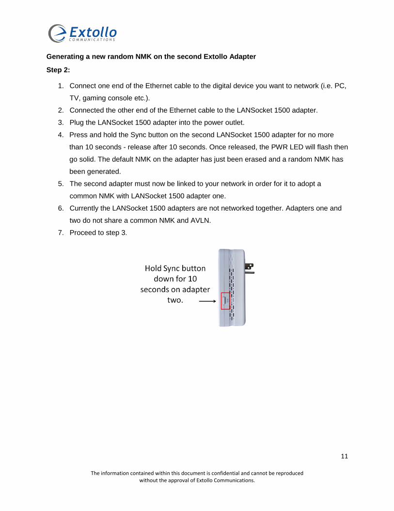
Generating a new random NMK on the second Extollo Adapter
Step 2:
1. Connect one end of the Ethernet cable to the digital device you want to network (i.e. PC,
TV, gaming console etc.).
2. Connected the other end of the Ethernet cable to the LANSocket 1500 adapter.
3. Plug the LANSocket 1500 adapter into the power outlet.
4. Press and hold the Sync button on the second LANSocket 1500 adapter for no more
than 10 seconds - release after 10 seconds. Once released, the PWR LED will flash then
go solid. The default NMK on the adapter has just been erased and a random NMK has
been generated.
5. The second adapter must now be linked to your network in order for it to adopt a
common NMK with LANSocket 1500 adapter one.
6. Currently the LANSocket 1500 adapters are not networked together. Adapters one and
two do not share a common NMK and AVLN.
7. Proceed to step 3.

12
The information contained within this document is confidential and cannot be reproduced without the approval of Extollo Communications.
Configuring a common NMK and a private AVLN
Step 3:
1. Ensure that the LANSocket 1500 adapters one and two are still plugged into the
power outlet.
2. On adapter one, press and hold the Sync button for 3 seconds then release.
3. The PWR LED on adapter one will start to flash. It is now in an adder state.
4. Within 120 seconds of the PWR LED on adapter one starting to flash, proceed to
adapter two.
5. On adapter two, press and hold the Sync button for 3 seconds then release. The
PWR LED will flash and go into a joiner state. When the PWR LED goes into a solid
state (no longer flashing), it means that adapter one is now paired with adapter two.
6. Both adapters are now networked together with a common NMK within a private
AVLN.

13
The information contained within this document is confidential and cannot be reproduced without the approval of Extollo Communications.
HomePlug AV & AV2 Pairing Overview Generally, Extollo’s HomePlug PLC adapters come 2 to a kit and are “paired” from the factory with the default (HomePlugAV) NMK. They are considered as “members of the same network”. No user interactions are required to add additional adapters to the AVLN. Simply plug in additional adapter(s) and they will join the existing AVLN and start networking with the adapters on the powerlines.
If a user creates a “Private AVLN”, only adapters possessing the same NMK can join the AVLN. Since private AVLN’s generate random NMK’s, the only method for a new adapter to join the private AVLN is by obtaining the NMK from the private AVLN. This is referred to as the “Pairing” process.
It is important to have at least 2 Extollo HomePlug PLC adapters with the same NMK that are already networked together on the private AVLN. They are considered as the “reference” network to join when adding additional adapters.
The pairing procedure will work if no Ethernet cable is connected to the LANSocket 1500 adapter and the device (PC, gaming console, STB etc.) that you’re networking. However, it is recommended that you connect the Ethernet cable to the devices that you are trying to network.
Please note that you can only add one LANSocket 1500 adapter to a private AVLN at a time. To add multiple adapters, please repeat the pairing process for each additional adapter.
The following procedure outlines the pairing process for adding additional LANSocket 1500 adapters to an existing private HomePlug powerline network
Pairing Configuration Procedure To add one or more LANSocket 1500 adapters to an existing private AVLN, please perform the following.
Step 1:
1. Plug the new LANSocket 1500 adapter into an electrical socket of the existing private
AVLN.
2. Connect the Ethernet cable to the LANSocket 1500 adapter and the device that is to be
networked (PC, gamming console, STB etc.).
3. To network the LANSocket 1500 adapter that you’re adding to the existing private AVLN
press and holding the Sync button for 10 seconds and then release the button. Once the
PWR LED has stopped flashing, advance to 4.

14
The information contained within this document is confidential and cannot be reproduced without the approval of Extollo Communications.
4. On the same LANSocket 1500 adapter, press and hold the Sync button for 3 seconds
and then release the button. The PWR LED will start flashing to indicate that the
LANSocket 1500 adapter is looking to join an AVLN.
Step 2: 5. Precede to one of the LANSocket 1500 adapters that are already installed in the
network.
6. Press and hold the Sync button for 3 seconds on one of the existing LANSocket 1500
adapters already installed in the network and then release the button (this operation
must be done in less than 2 minutes of item 4 in Step 1). The PWR LED will flash to
indicate that the LANSocket 1500 adapter is looking to add a PLC adapter to the private
AVLN.
7. After approximately 20 seconds (maximum), the PWR LEDs will stop flashing to indicate
that new LANSocket 1500 adapter has been paired with the existing PLC adapters on
the private AVLN.
8. Repeat steps 1 and 2 to add additional Extollo PLC adapters to the private AVLN.
15
The information contained within this document is confidential and cannot be reproduced without the approval of Extollo Communications.
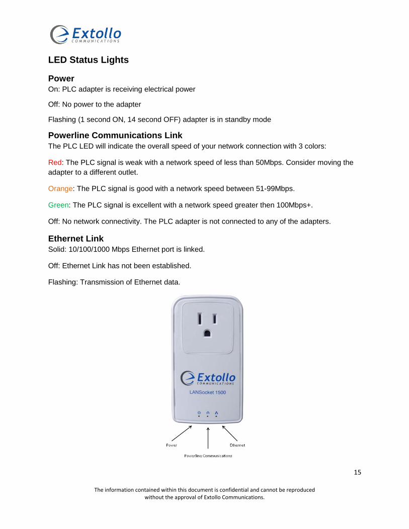
LED Status Lights
Power On: PLC adapter is receiving electrical power
Off: No power to the adapter
Flashing (1 second ON, 14 second OFF) adapter is in standby mode
Powerline Communications Link The PLC LED will indicate the overall speed of your network connection with 3 colors:
Red: The PLC signal is weak with a network speed of less than 50Mbps. Consider moving the adapter to a different outlet.
Orange: The PLC signal is good with a network speed between 51-99Mbps.
Green: The PLC signal is excellent with a network speed greater then 100Mbps+.
Off: No network connectivity. The PLC adapter is not connected to any of the adapters.
Ethernet Link Solid: 10/100/1000 Mbps Ethernet port is linked.
Off: Ethernet Link has not been established.
Flashing: Transmission of Ethernet data.

16
The information contained within this document is confidential and cannot be reproduced without the approval of Extollo Communications.
LANSocket 1500 Product Dimensions
17
The information contained within this document is confidential and cannot be reproduced without the approval of Extollo Communications.
Network Optimization
Extollo PLC adapters work better when plugged into a wall outlet without power strips, extension cords, surge protectors, or uninterruptable power supplies.
If you’re Extollo adapters are having difficulty communicating with each other, please read the following section for corrective actions.
Quick Tips
• Plug Extollo adapters directly into wall sockets. • Try plugging the Extollo adapter into an adjacent power outlet. • Try power cycling the unit - unplugging it from the power socket for 10 seconds and then
plugging it back in. • Make sure that the electrical outlet is working properly. • Do not use the Extollo adapters in areas with excessive heat.
Optimizing Network Performance
The distance between sockets shouldn’t be a problem in most homes, but the age of the electrical wiring may affect performance in some older buildings.
There are a few things to bear in mind if you want to get the best performance from your powerline network.
• Avoid UPS devices, GFI protected outlets, power strips, multi-way extensions or extension cords as these will cause the PLC signal to attenuate (weaken).
• Surge protectors in particular interfere with the operation of powerline adapters. • Some electrical devices, such as mobile phone chargers, certain florescent or
incandescent lights can cause interference or completely block the PLC signals if they’re plugged in to close to the Extollo adapter.
• Avoid using HomePlug 1.0 adapters with HomePlug AV and AV2 adapters as they are relatively slow and not compatible.
Reset to factory default
The following procedure will set your Extollo PLC adapter to factory default settings.
1. Hold the Sync button down for more than 15 seconds. 2. The PWR (power) LED light will flash. 3. The unit will reset and attempt to link using default factory settings.

18
The information contained within this document is confidential and cannot be reproduced without the approval of Extollo Communications.
Troubleshooting The following information will help in isolating problems with Extollo PLC adapters.
Symptoms None of the LED’s light up after the adapter is installed:
• Unplug the adapter from the electrical outlet and remove the Ethernet cable. • Make sure there is power to the electrical outlet and it’s working properly. • Ensure the adapter is not plugged into an extension cord, power strip, or surge
protector.
Power (PWR) LED is off:
• Make sure there is power supplied to the electrical outlet. • Ensure the Extollo PLC adapter is securely plugged directly to the electrical outlet. • Try another electrical outlet.
Power (PWR) LED is flashing1 second ON, 14 second OFF: • The adapter is in standby/power saving mode.
Powerline (PLC) LED is off - the adapter is not communicating with the other adapters:
• Reset the adapter to factory defaults. • If a private AVLN was created, perform the pairing process again. • Try a different electrical outlet.
The Ethernet LED does not light up on the adapter: • The Ethernet LED indicator on the Powerline adapter will light up once it detects a
network device plugged into the Ethernet port. • Check if the Ethernet cable is securely connected to the Powerline adapter. • Make sure that the Ethernet cable is properly connected to the router, computer or any
of the network devices. • Make sure that the device you are connecting to the Powerline adapter is powered ON. • Check the Ethernet adapter on your computer to see if it is working. • Try a different Ethernet cable.
The Extollo adapter suddenly stops working • Perform a power cycle of the adapter.

19
The information contained within this document is confidential and cannot be reproduced without the approval of Extollo Communications.
Specifications
Main Chipset Broadcom 960500
Computer Interface IEEE802.3 /u/ab 10/100/1000 BASE-T
Data PHY Rate 1.8 Gbps
MIMO 2x2 Multiple-In Multiple-Out
Standards HomePlug AV2, TR-069 data model 181
Network Interface One RJ-45 (10/100/1000Base-T Ethernet) One 1.8Gbps Power Line interface
Quality of Service Four level round robin queue with priority contention channel access control
Security 128-bit AES Link Encryption with Key Management
Frequency Band 2-86 MHz
Modulation Schemes OFDM Symbol Modulation on Line synchronization
1024/256/64/16/8—QAM, QPSK, BPSK, ROBO Carrier Modulation Protocols Mix of TDMA and CSMA/CA channel access scheme; CO device
generates a periodic beacon carrier for channel access scheme Operational Range Estimated range of 985 feet (300 meters) across power lines
Cabling 100Base-T; Cat. 5 UTP Cable
Operating Temperature 0° C to 50° C ambient temperature
Storage Temperature -20° C to 70° C ambient temperature
Humidity 10% to 90% maximum (non-condensing)
Power Input 100 ~ 240V @ 50/60Hz Internal
Housing Plastic: H4.45” x W2.51” x D1.65” (113mm x 64mm x 42mm)
Status Lights Power: On/Off/Flashing 1 second ON, 14 seconds OFF (Standby Mode) PLC (Powerline) Link: Red/Orange/Green/Off Ethernet Link: Solid/Off/Flashing
Certifications HomePlug AV Powerline Certification
FCC Class B / CE Mark