large-eddy simulation of the flow developing in static and
TRANSCRIPT
Florent Duchaine1
CFD Team CERFACS,Toulouse, France
e-mail: [email protected]
Laurent GicquelCFD Team CERFACS,
Toulouse, Francee-mail: [email protected]
Thomas Grosnickel2
CFD Team CERFACS,Toulouse, France
e-mail: [email protected]
Charlie KoupperSafran Helicopter Engine,
Bordes, Francee-mail: [email protected]
Large-Eddy Simulation of theFlow Developing in Static andRotating Ribbed ChannelsIn the present work, the turbulent flow fields in a static and rotating ribbed channelrepresentative of an aeronautical gas turbine are investigated by the means of wall-resolvedcompressible large-Eddy simulation (LES). This approach has been previously validated ina squared ribbed channel based on an experimental database from the Von Karman Insti-tute (Reynolds and rotation numbers of about 15,000 and ±0.38, respectively). LES resultsprove to reproduce differences induced by buoyancy in the near rib region and resultingfrom adiabatic or anisothermal flows under rotation. The model also manages to predictthe turbulence increase (decrease) around the rib in destabilizing (stabilizing) rotation ofthe ribbed channels. On this basis, this paper investigates in more detail the spatial devel-opment of the flow along the channel and its potential impact on secondary flow structures.More specifically and for all simulations, results of the adiabatic static case exhibit twocontra-rotating structures that are close to the lateral walls of the channel induced by trans-versal pressure difference created by the ribs. These structures are generated after the firstribs and appear behind all inter-rib sections, their relative position is partly affected byrotation. When considering the stabilizing rotating case, two additional contra-rotatingstructures also develop along the channel from the entrance close to the low-pressurewall (rib-mounted side). These vortices are due to the confinement of the configuration,inflow profile and are the result of Coriolis forces induced by rotation. Görtler vorticesalso appear on the pressure wall (opposite to the rib-mounted side). In the destabilizingrotating case, these two types of secondary structures are found to co-exist, and their migra-tion in the channel is significantly different due to the presence of the ribs on the pressureside. Finally, it is shown that heat transfer affects only marginally the static and stabilizedcases while it changes more significantly the flow organization in the destabilizing casemainly because of enhanced heat transfer and increased buoyancy force effects.[DOI: 10.1115/1.4046267]
Keywords: computational fluid dynamics (CFD), large-Eddy simulation (LES), heattransfer and film cooling
IntroductionNeed for increased efficiency as well as power for gas turbine
engines, accompanied by the need for cleaner engines, results inever-increasing combustor exit temperature with the appearanceof hot spots that well surpass existing melting materials currentlyavailable for turbine components. To guarantee life span and keepmaterial constraints under acceptable limits, rotating and staticparts of the first turbine stage require heavy cooling which can beobtained through various technological choices. In the case of rotat-ing wheels, cooling channels are usually built in the blade solidmaterial so as to extract as much heat as possible from the bladesurface to alleviate the heat load resulting from the hot stream inthe vein. To enhance heat extraction from the solid to the internalchannel flow, while promoting mixing, obstacles are usuallyadded to the channel, the objective is to maximize heat extractingwhile diminishing as much as possible pressure losses. Althoughpresent since a long time in the design of aeronautical engines,this specific problem remains highly misunderstood mainly due tothe complex flow physics present in such conditions. Not onlyheat transfer is present at the interface between the solid part andthe internal flow, but also rotation speeds are usually large and
buoyancy, which may appear impacting significant flow responses.Numerical approaches to solve these flows are in industry: Rey-nolds-averaged Navier–Stokes (RANS), unsteady-RANS [1,2],and more recently point to large-Eddy simulations (LESs) [3–5].Particular attention is put in the present work on the flow develop-ment along the channel with a special focus on secondary flows andthe effect of rotation in stabilizing, static, and destabilizing condi-tions with LES. Contrarily to most literature studies on suchflows, real geometries are complex and short which is not fully rep-resentative of most works where the flow is assumed to be fullydeveloped flows. One objective is thus to address the spatial devel-opment of such flows and more specifically its impact on secondaryflow features as they appear through the channel for different oper-ating conditions, i.e., in stabilizing, static, destabilizing, and adia-batic or non-isothermal conditions.The expected dynamics for a rotating straight channel can be
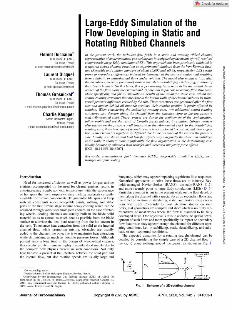
detailed by considering the simple case of a 2D channel flow inthe (x, y) plane rotating around the z-axis, as shown in Fig. 1.
Fig. 1 Scheme of a 2D-rotating channel
1Corresponding author.2Present address: Safran Helicopter Engines, Bordes, France.Contributed by the International Gas Turbine Institute (IGTI) of ASME for
publication in the JOURNAL OF TURBOMACHINERY. Manuscript received October 30,2019; final manuscript received January 13, 2020; published online February 6,2020. Assoc. Editor: David G. Bogard.
Journal of Turbomachinery APRIL 2020, Vol. 142 / 041003-1Copyright © 2020 by ASME
Dow
nloaded from https://asm
edigitalcollection.asme.org/turbom
achinery/article-pdf/142/4/041003/6488965/turbo_142_4_041003.pdf by CER
FACS user on 05 M
arch 2020

Due to rotation, the Coriolis force will balance the wall-normalpressure gradient that will mark the mean flow profile as evidencedin Fig. 1. For this specific flow profile, stability analyses developedby Bradshow et al. [6] underline that boundary layers on the pres-sure side (bottom part for this specific rotation) will destabilize,while the ones on the suction side will stabilize. The main impacton the flow quantities of such differences in stability is a directchange in the near-wall turbulence levels. More precisely, the stabi-lized (destabilized) side sees a decrease (increase) in turbulenceintensity, implying an increase in symmetry loss of the main flowvelocity profile when compared with a laminar rotating channel.Previous observations have been experimentally reported by John-ston et al. [7] and later confirmed by the direct numerical simulationof Kristoffersen and Andersson [8] and Lamballais et al. [9].Addition of ribs on the bottom side of the above-discussed
channel, turbulent flow in the vicinity of the ribs will be eitherfurther stabilized or destabilized when the channel is rotating inthe negative/positive direction for the reasons detailed above butapplied to an already turbulent flow. Rib size relative to the initialsmooth channel height will of course be of importance just likethe operating flow condition: i.e., base flow Reynolds number androtational speed. All of these observations were partly confirmedby previous LES studies on such problems postulating either inthe experiments or numerically that the flow is fully developed.Such a state is however not guaranteed and may appear only aftera specific distance from the inflow condition. This distance of estab-lishment is in itself not fully understood and depends on manyparameters including the inflow state. More specifically, for realengine applications, it is often reported that the flow in coolingrotating blade channels never reaches this ideal fully developedstate. Therefore, the computational fluid dynamics tool validationneeds to highlight such point as discussed hereafter for an experi-mental benchmark test case from the Von Karman Institute (VKI).This paper is organized as follows. First, the experimental setup
is presented followed by a description of the numerical method usedto simulate the test rig. Then, general considerations on the flowdevelopment along the ribbed channel are provided, and numericalresults are validated through comparisons with the experimentaldata. Finally, the last section details the sensitivity of the secondaryflow structure to the operating point.
Experimental Test CaseTo analyze the flow development in static and rotating heated
ribbed channels, the rotating VKI experimental facility by Di
Sante et al. [10] is investigated. The rig is equipped with anon-board PIV system that allows to measure classical mean velocityquantities from uncorrelated time windows as well as fluctuatingquantities resolved in time. The experimental test section is pre-sented in Fig. 2 [11]. It consists of a straight square channel installedon a rotating wooden disc with eight ribs mounted on one side of thechannel. The ribs are square with a section of h× h= 8 × 8 mm2 andare placed perpendicular to the main flow. The distance separatingthe ribs is pitch= 80 mm. The geometrical characteristics of thechannel are summarized in Table 1. Three cases will be investi-gated: static channel, positive and negative rotation with respectto the trigonometry direction. The rotation speed retained for thisstudy is around 130 rpm yielding a rotation number Ro= 0.38defined as
Ro =ΩDh
Ub(1)
where Ω, Dh, and Ub are, respectively, rotation speed, channelhydraulic diameter, and bulk velocity of the flow. For these condi-tions, the Reynolds number based on the bulk velocity and hydrau-lic diameter is 15,000. Experimentally, the flow comes from thecenter of the disk through an elbow and is straightened by a honey-comb before entering the channel. Another honeycomb is placed atthe outlet of the channel to avoid perturbation of the flow in the testsection by ambient flow perturbations when rotating.Figure 2 illustrates the channel via a side view. The PIV system
allows to perform measurement on six windows. Two of them (waand wb) are located at the inlet of the test section providing infor-mation for inlet conditions of numerical simulations. The otherwindows (w1–w4) are placed between ribs 6 and 7, covering onlyone-third of the channel height.
Numerical MethodLES Solver. The LES solver AVBP [12] developed by
CERFACS and IFPEN is used to solve the filtered compressibleNavier–Stokes (NS) equations. This solver runs efficiently on mas-sively parallel machines and handles unstructured mesh allowingthe easiest meshing of complex geometries when compared withstructured grids [13]. The convective terms are discretized withan explicit two-step Taylor Galerkin finite element scheme basedon a cell vertex formulation [14]. This numerical scheme hasgood spectral properties (low dissipation and dispersion) and fea-tures a third-order accuracy in time and space as required forhigh-fidelity LES. A second-order Galerkin scheme is used forthe diffusion terms [15]. As the temporal integration is explicit,the time-step is limited by the acoustic Courant–Friedrichs–Lewynumber which is set to 0.7. The resulting time-step controlled bythe size of the smallest cells located close to ribbed walls is of theorder of dt≈ 0.6 μs. The sub-grid scale (SGS) viscosity νt isobtained by the wall adapting local Eddy-viscosity model [16].This model is well suited for wall-resolved wall-bounded flows asit is constructed to recover the scaling laws of turbulent viscosityat walls [16]. A classical gradient-diffusion hypothesis is used tocompute SGS heat fluxes [17]. SGS heat fluxes are computedwith the filtered temperature gradient using an SGS thermal
Table 1 Summary of ribbed channel characteristics
Channel length, l 760 mmChannel height, H 83 mmChannel depth, w 75 mmDh 79 mmRibs height, h 8 mmBlockage ratio, h/Dh 0.1Pitch, p/h 10Ribs angle 90 deg
Fig. 2 Experimental test bench: schematic lateral view of the PIV zones not at scale
041003-2 / Vol. 142, APRIL 2020 Transactions of the ASME
Dow
nloaded from https://asm
edigitalcollection.asme.org/turbom
achinery/article-pdf/142/4/041003/6488965/turbo_142_4_041003.pdf by CER
FACS user on 05 M
arch 2020

conductivity λt, which is linked to the SGS viscosity νt through anSGS turbulent Prandtl number here fixed at Prt = 0.6.
Boundary Conditions and Mesh. The numerical domainretained for the present study is presented in Fig. 3. Velocity profilesmeasured experimentally for the different cases are imposed at theinlet along with a uniform temperature, T0= 293 K, using theNavier–Stokes characteristic boundary condition (NSCBC) formal-ism [18]. No turbulent fluctuations are added since the experimentalinlet has been designed to obtain a symmetric inlet velocity profile,free of secondary flows, and with a turbulent intensity lower than1% [5]. At the outlet, static pressure is enforced using theNSCBC formalism accounting for the transverse terms [19]. Allwalls (S, T, and R of Fig. 3) are adiabatic, and no-slip for the refer-ence adiabatic cases. Dealing with anisothermal cases, the flow isheated by the bottom wall (R) using a Neumann iso-flux andno-slip boundary condition.
To accurately resolve the aerodynamic and thermal boundarylayer in a wall-resolved framework at minimal cost when comparedwith a full tetrahedral mesh, a hybrid tetrahedra/prismatic gridapproach is adopted. Indeed, for the same spatial resolution in thenormal direction, a prism layer uses less elements and leads to ahigher minimum cell volume than a full tetrahedral-grid approachas prismatic elements can have a large aspect ratio. All the wallsare meshed with a layer of prismatic elements where the height ofthe prisms is smaller than the size of their triangle basis by a ratioof about 5 to control numerical errors. The mesh used for thestatic and negative rotation cases has 3.6 million cells with amean y+ on the ribbed wall (R) of about 3 without exceeding 5as required for a wall-resolved LES (Fig. 4). The characteristicsof this mesh are the result of a convergence study performed byFransen et al. [2] and used by Scholl et al. [20] as well as Grosnickelet al. [21]. Concerning the positive rotation, the destabilization ofthe flow due to rotation takes place close to the ribbed wall. As aconsequence, a finer mesh of 9.5 million cells is used as described
Fig. 3 Scheme of the numerical domain
Fig. 4 Distribution of y+ on the ribbedwall for the (a) positive rotation, (b) static, and(c) negative rotation cases in the adiabatic condition (gray on the bottom ribbed walland black on the ribs)
Journal of Turbomachinery APRIL 2020, Vol. 142 / 041003-3
Dow
nloaded from https://asm
edigitalcollection.asme.org/turbom
achinery/article-pdf/142/4/041003/6488965/turbo_142_4_041003.pdf by CER
FACS user on 05 M
arch 2020

in Grosnickel et al. [21]. The mean y+ for this refined mesh is alsoabout 3 without exceeding 9 on the ribbed wall (Fig. 4).The rotation of the domain for the positive and negative cases is
performed by moving the mesh in a solid rotation using an arbitraryLagrangian-Eulerian framework [22,23]. This approach removesthe need for correcting the Navier–Stokes equations since rotationis transmitted implicitly to the flow-through moving boundariesand mesh points as commonly done in other studies [24–28].
General Considerations on Flow DevelopmentThis section presents general considerations about flow develop-
ment along the channel in static and rotating cases for adiabatic andthen anisothermal conditions. As illustrated in Fig. 5, the flow at theinlet of the channel is smooth and quasi-laminar. Shear layersappear after the first rib before to be destabilized by the followingribs leading to a highly turbulent flow. The time-averaged flowtopology is thus directly impacted by the predicted flow develop-ment and the ability of the solver to well reproduce the relevant fea-tures in space is of primary importance. Although the study ofturbulent structures organization is of interest in this configuration,the analyses proposed in this paper focus on the mean topology ofthe flow only. To do so, time-averaged field obtained on 3 flow-through times of the whole configuration corresponding to about30 characteristic convection time between two successive ribs isinvestigated.Figure 6 illustrates the spatial development of the flow through
the time-averaged axial velocity field in the symmetry plane ofthe configuration for the adiabatic test cases in static, negative,
and positive rotations. In these three cases, the global behavior ofthe flow is similar: ribs induce a blockage resulting in a deviationof the flow toward the opposite wall with an elevation in the veloc-ity. The flow topology in the region close to the ribs also presentssimilar patterns among cases. Indeed, several recirculation zonesestablish downstream, upstream, and above the ribs and will moredeeply investigated later. It is worth noting that in the three operat-ing conditions, the flow appears to be almost established and fullydeveloped after the first three ribs. Indeed, in each case, the recircu-lation zones located in-between the three first ribs are larger thanfurther downstream where this region of the flow appears to bequasi-periodic along the streamwise direction. When comparingthe operating conditions, the main difference between the staticand rotating cases lies first in the size of the main recirculationzone downstream of the ribs after the development within thechannel. The size of this zone is directly linked to the turbulencelevels in the channel and thus to the stabilizing and destabilizinginduced by the rotation. The stabilizing and destabilizing effectsof the negative and positive rotations are, respectively, confirmedby Fig. 7 where the fluctuations of the axial velocity are displayedthrough the axial velocity root-mean-squares (RMSs) in the symme-try plane of the channel. Due to the transition into a turbulent flowevidenced in Fig. 5 for the static case, axial velocity RMS startsonly to increase around the second rib. The primary source of thisturbulence generation is the apparition of the rib-induced shearlayers which become unsteady resulting in high RMS spots forthe static condition. The negative rotation is here observed to stabi-lize the shear layers resulting in lower levels of RMS all along thechannel when compared with the static case. On the contrary, thedestabilizing effect of the positive rotation enhances the axial
Fig. 5 Q-criterion colored by the normalized axial velocity in the domain and vorticitymagnitude in the symmetry plane based on an instantaneous solution of the VKIchannel configuration in the static condition
Fig. 6 Time-averaged normalized axial velocity on the symmetry plane for the(a) positive rotation, (b) static, and (c) negative rotation cases in the adiabaticcondition
041003-4 / Vol. 142, APRIL 2020 Transactions of the ASME
Dow
nloaded from https://asm
edigitalcollection.asme.org/turbom
achinery/article-pdf/142/4/041003/6488965/turbo_142_4_041003.pdf by CER
FACS user on 05 M
arch 2020
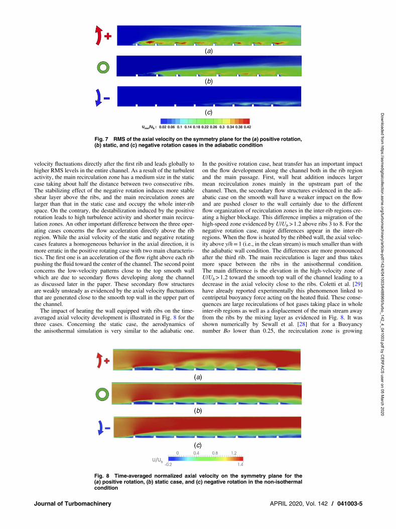
velocity fluctuations directly after the first rib and leads globally tohigher RMS levels in the entire channel. As a result of the turbulentactivity, the main recirculation zone has a medium size in the staticcase taking about half the distance between two consecutive ribs.The stabilizing effect of the negative rotation induces more stableshear layer above the ribs, and the main recirculation zones arelarger than that in the static case and occupy the whole inter-ribspace. On the contrary, the destabilization induced by the positiverotation leads to high turbulence activity and shorter main recircu-lation zones. An other important difference between the three oper-ating cases concerns the flow acceleration directly above the ribregion. While the axial velocity of the static and negative rotatingcases features a homogeneous behavior in the axial direction, it ismore erratic in the positive rotating case with two main characteris-tics. The first one is an acceleration of the flow right above each ribpushing the fluid toward the center of the channel. The second pointconcerns the low-velocity patterns close to the top smooth wallwhich are due to secondary flows developing along the channelas discussed later in the paper. These secondary flow structuresare weakly unsteady as evidenced by the axial velocity fluctuationsthat are generated close to the smooth top wall in the upper part ofthe channel.The impact of heating the wall equipped with ribs on the time-
averaged axial velocity development is illustrated in Fig. 8 for thethree cases. Concerning the static case, the aerodynamics ofthe anisothermal simulation is very similar to the adiabatic one.
In the positive rotation case, heat transfer has an important impacton the flow development along the channel both in the rib regionand the main passage. First, wall heat addition induces largermean recirculation zones mainly in the upstream part of thechannel. Then, the secondary flow structures evidenced in the adi-abatic case on the smooth wall have a weaker impact on the flowand are pushed closer to the wall certainly due to the differentflow organization of recirculation zones in the inter-rib regions cre-ating a higher blockage. This difference implies a migration of thehigh-speed zone evidenced by U/Ub> 1.2 above ribs 3 to 8. For thenegative rotation case, major differences appear in the inter-ribregions. When the flow is heated by the ribbed wall, the axial veloc-ity above y/h= 1 (i.e., in the clean stream) is much smaller than withthe adiabatic wall condition. The differences are more pronouncedafter the third rib. The main recirculation is lager and thus takesmore space between the ribs in the anisothermal condition.The main difference is the elevation in the high-velocity zone ofU/Ub> 1.2 toward the smooth top wall of the channel leading to adecrease in the axial velocity close to the ribs. Coletti et al. [29]have already reported experimentally this phenomenon linked tocentripetal buoyancy force acting on the heated fluid. These conse-quences are large recirculations of hot gases taking place in wholeinter-rib regions as well as a displacement of the main stream awayfrom the ribs by the mixing layer as evidenced in Fig. 8. It wasshown numerically by Sewall et al. [28] that for a Buoyancynumber Bo lower than 0.25, the recirculation zone is growing
Fig. 7 RMS of the axial velocity on the symmetry plane for the (a) positive rotation,(b) static, and (c) negative rotation cases in the adiabatic condition
Fig. 8 Time-averaged normalized axial velocity on the symmetry plane for the(a) positive rotation, (b) static case, and (c) negative rotation in the non-isothermalcondition
Journal of Turbomachinery APRIL 2020, Vol. 142 / 041003-5
Dow
nloaded from https://asm
edigitalcollection.asme.org/turbom
achinery/article-pdf/142/4/041003/6488965/turbo_142_4_041003.pdf by CER
FACS user on 05 M
arch 2020

when increasing Bo, and for Bo> 0.25, the recirculation takes all theinter-rib space, with Bo defined as:
Bo(r) = rΩ2 Dh
U20
Tw − T0T0
(2)
where r is the local radius, rΩ2 is the centrifugal force, and Tw is thewall temperature, while U0 and T0 are, respectively, the bulk veloc-ity and bulk temperature. Buoyancy is mainly driven not only by thetemperature difference issued by the wall and the fluid but also bythe rotation number. In the present case, Bo= 0.2 corresponds to thethird rib location where the flow topology starts to change illustrat-ing a strong coupling between aerodynamics and heat transfer in thestudied anisothermal operating condition.
Validations of Large-Eddy Simulation ResultsThe validation of the different LES results is obtained by compar-
ing time-averaged axial velocity fields from the computations withexperimental data in the region between ribs 6 and 7 as shown inFig. 2. The recirculation zones between these two ribs for the differ-ent operating points (adiabatic/heat flux, static/rotating cases) arevisualized by the use of restricted 2D streamlines in the symmetryplane and are represented in Fig. 9. The discontinuities in the
experimental fields are due to the different PIV acquisitionwindows illustrated in Fig. 2. As mentioned, the thermal conditiondoes not affect the aerodynamics of the static case so only the adi-abatic case is represented. For this specific case, the LES well repro-duces the size of the four recirculation zones : main recirculationdownstream of rib 6 which rotates clockwise, the induced bubbleclose to rib 6 foot rotating anti-clockwise, and the recirculationzones before and on top of rib 7 that rotates clockwise. The mainmodifications of these recirculation zones induced by positive andnegative rotations are well captured by the simulations: a reductionof the principal recirculation zone for the positive destabilizing rota-tion and an increase in the case of the negative stabilizing rotation.Simulation and experimental results compare also well when heattransfer is added: the enlargement of the main recirculation zoneis well predicted by LES in both rotating cases.Figure 10 shows more quantitative comparisons by directly com-
paring profiles at various axial positions in the inter-rib section asobtained by the computations and measurements for the adiabaticcondition. This further confirms the ability of LES to reproducethe experimental axial velocity in the static and rotating cases.The intensity of the main recirculation zone and the velocitylevels reached outside the rib region (around y/h= 2) is also wellpredicted for all three operating conditions. The velocity fluctua-tions are also well predicted for the three cases as illustrated by
Fig. 9 Streamlines based on time-averaged velocity between ribs 6 and 7 for the (a) positiverotation, (b) static, and (c) negative rotation under adiabatic and anisothermal conditions
041003-6 / Vol. 142, APRIL 2020 Transactions of the ASME
Dow
nloaded from https://asm
edigitalcollection.asme.org/turbom
achinery/article-pdf/142/4/041003/6488965/turbo_142_4_041003.pdf by CER
FACS user on 05 M
arch 2020

Fig. 11 where the axial velocity RMS profiles obtained by LES arecompared with experimental measurements. The topology of theprofiles is well captured by the simulations with the peak of activityin the shear layer induced by the separation behind the rib. A slightoverestimation of the RMS levels at this peak is observed at someaxial locations for the positive and static cases. On the contrary,the negative case LES result exhibits a global underestimation ofthe RMS when compared with measurements. It seems that thenumerical method (mesh, numerical scheme as well as SGSmodel) leads to a more pronounced stabilization for the negativerotation than in the experiment.Figure 12 shows the impact of imposing an isothermal boundary
condition on the ribbed wall for the static and the two rotating casesin the region of interest that is between ribs 6 and 7. As anticipatedfrom the previous section, when the channel is rotating, bigger dif-ferences appear between adiabatic condition and isothermal onethan in the static case. For the positive rotation case, the major mod-ification concerns the increase in intensity and size of the main recir-culation zone after rib 6. When the wall is heated, the recirculationbecomes stronger with a more important negative axial velocitywhen y/h< 1. The size of the recirculation zone between thetwo ribs is also larger: reattachment occurs between x/h= 4 and x/h= 5 for the adiabatic case while the flow is still recirculating atx/h= 9 for the anisothermal case. Finally, no important differenceexists close to the channel’s center for y/h above 1.5. For the nega-tive rotation case, the main recirculation zone is slightly moreimportant. The main difference in this case lies in the level ofaxial velocity in the region just above the ribs (1 < y/h< 3) whichis lower in the anisothermal case due to an increase of the blockageinduced by buoyancy and affecting the inter-rib region. The LES/experiment comparison is good, especially in the vicinity of theribs even if LES predicts a junction of the adiabatic and anisother-mal profile for higher values of y/h than the experimental results.To characterize wall heat transfer, the enhancement factor (EF)
that compares the local Nusselt number Nu to a reference Nusselt
number Nu0 is used:
EF =NuNu0
(3)
In this work, the reference Nusselt number is obtained with theDittus–Boelter relation Nu0 = 0.023Re0.8Pr0.4. Several possibilitiesexist to compute the Nusselt number Nu. The methodology toobtain Nu with LES data which slightly differs from the experimen-tal protocol [5] is exposed hereafter. The Nusselt number is numer-ically computed by
Nu =hcDh
λ(4)
where λ is the thermal conductivity at the wall temperature. The heattransfer coefficient hc is determined following the regressionmethod proposed by Fenot et al. [30] using four LES for each rotat-ing condition with four different wall heat fluxes qw= 500, 1000,1500, and 2000 W/m2. As the determination of the Nusseltnumber differs between the experimental and numerical protocols,only the shape of the EF on the wall between ribs 6 and 7 presentedin Fig. 13 can be compared. The global tendency of EF augmenta-tion for a positive rotation due to flow destabilization as well as EFreduction for the negative rotation due to flow stabilization andlarger recirculation induced by buoyancy forces discussed beforeis well captured by the computations. Then, the general patternsare well predicted by the LES. The first important aspect isthe longitudinal organization with a low heat transfer close to rib6 (0≤ x/h≤ 1) due to the induced recirculation bubble visible foreach operating point. Second, every case exhibits lateral patternsdue to secondary flows that will be discussed in more detail inthe section dedicated to secondary flow analysis. The LES repro-duce the EF increase in the lateral corners for negative as well aspositive rotation for which this effect is more pronounced.
Fig. 10 Time-averaged axial velocity profiles between ribs 6 and 7 from adiabaticLES (lines) and PIV (symbols): (a) positive rotation, (b) static, and (c) negativerotation
Journal of Turbomachinery APRIL 2020, Vol. 142 / 041003-7
Dow
nloaded from https://asm
edigitalcollection.asme.org/turbom
achinery/article-pdf/142/4/041003/6488965/turbo_142_4_041003.pdf by CER
FACS user on 05 M
arch 2020

To conclude this section, the unsteady simulations performedwith LES are able to reproduce with a high fidelity the meanaxial velocity measured experimentally in the region between ribs6 and 7 for the different operating points: static and rotating aswell as adiabatic and with heat transfer applied to the ribbed wall.The same conclusion can be drawn on transverse velocity as wellas on RMS. These LES/experiment agreements confirm that thecomputations also well capture the development of the flow topol-ogy along the channel and that such effects need to be carefully cap-tured for specific these conditions since no true fully developed flowis effectively obtained here. This observation was found to be espe-cially critical in the destabilizing adiabatic condition. As shown pre-viously, the flow development is highly dependent on the operatingcondition and a fully periodic behavior is not reached at the end ofthe channel mainly for the negative rotation case and potentially butto a lesser extent for other conditions. For the negative rotation, sec-ondary flows on the smooth wall opposite to rib wall are observed toplay an important role in the velocity distribution within the channeland therefore in the inter-rib spacing as the flow develops. Such afeature was also found to depend on the inflow profile [21]. Thenext section discusses in more detail the secondary flow structuresfor this configuration as well as their sensitivities to rotation andwall heat flux.
Secondary Flow StructuresComparisons of the temporally averaged mean axial velocity
maps in the symmetry plane of the configuration confirm that flowestablishment within the channel from the inlet section to its fullydeveloped state is a strong function of the operating condition. Onereason for such behaviors relates to the flow organization andflow response to the rib-induced blockage and more specifically
to the generation of secondary flows that can be prompted byrotation. The result is different competitive forces acting on themain axial stream and resulting in different transversal flow organi-zations. These features are first studied for the adiabatic cases inFig. 14 by focusing on four transversal planes located throughthe channel and positioned, respectively, at (a), (e), and ( j): mid-distance between the inlet and the first rib; (b),( f ), and ( j): mid-distance between the second and third rib; (c), (g), and (k):mid-distance between the fourth and fifth rib; and (d ), (h), and (l ):mid-distance between the sixth and seventh rib. All frames showthe non-dimensional mean axial velocity field within the transversalsection of the channel with the addition of streamlines restrained tothis plane to evidence flow recirculations and overall organizationin each transversal plane.Focusing first on the reference case that is the static adiabatic
channel, Figs. 14(e)–14(h), distinct and well-identified secondaryflow structures establish as it proceeds through the channel. Initiallyunperturbed and solely axial in the first section, Fig. 14(e), the flowis rapidly affected by the presence of the ribs on the bottom sectionby generating two contra-rotating structures induced by the con-junction of the lateral walls and the rib-induced pressure gradient.As a result and at mid-distance in the inter-rib passage, twoslowly rotating structures located at mid-height in the passage redis-tribute the flow extracting mass from the inter-rib region along thelateral walls and injecting mass from the main channel stream in theinter-rib region in the symmetry plane of the configuration. Addi-tionally to these two main features, four contra-rotating appear onthe bottom wall in Fig. 14( f ) whose height appears to scale withthe rib height and seem to remain in latter sections but appear tobe much weaker. Focusing on the stabilizing case, Figs. 14(i)–14(l ), a clear impact of rotation is evidenced. Although stabilizing,secondary structures are more diverse and appear. Dissymmetry inthe first section, Fig. 14(i), is explained through the inflow condition
Fig. 11 RMS of axial velocity between ribs 6 and 7 from adiabatic LES (lines) and PIV (symbols):(a) positive rotation, (b) static, and (c) negative rotation
041003-8 / Vol. 142, APRIL 2020 Transactions of the ASME
Dow
nloaded from https://asm
edigitalcollection.asme.org/turbom
achinery/article-pdf/142/4/041003/6488965/turbo_142_4_041003.pdf by CER
FACS user on 05 M
arch 2020

Fig. 12 Time-averaged axial velocity profiles between ribs 6 and 7 from adiabatic and anisother-mal LES (lines) and PIV (symbols): (a) positive rotation, (b) static, and (c) negative rotation
Fig. 13 Enhancement factor contours obtained experimentally (up) and numeri-cally (down) for the rotating and static cases between ribs 6 and 7
Journal of Turbomachinery APRIL 2020, Vol. 142 / 041003-9
Dow
nloaded from https://asm
edigitalcollection.asme.org/turbom
achinery/article-pdf/142/4/041003/6488965/turbo_142_4_041003.pdf by CER
FACS user on 05 M
arch 2020

that is specified in agreement with measurements and Fig. 1. Theconsequence of this inflow modification and presence of the ribsis the separation of the channel cross section into two distinctflow region: (a) the bottom half of the channel including the inter-rib region produces an overall flow organization similar to the staticchannel case but in half the spatial extent and (b) the top part of thechannel or pressure side in this specific case, which produces fourvortices assimilated to Taylor–Görtler [31] structures. These laterclearly appear as going through the channel, gaining in strengthto a point where they potentially interact and migrate within thetop section of the channel. One other important feature that distin-guishes this flow from the static case is the apparent confinement tothe lateral walls of two rotation-induced contra-rotating vortices.These are present directly after the entree section migrates slowlyabove the ribs and accentuates the previously identified downwardflow observed in the static case. This case distinguishes itself fromthe previous one by the fact that the downward flow starts from themid-section flow to the inter-rib region when it appears to comefrom the top section of the channel flow in the static case. It further-more covers a smaller transversal extent in the static case. Likewise,the dynamics in the inter-rib region appears to be stronger with the
existence of four sustained vortices directly behind the ribs throughthe entire length of the channel. Switching to the destabilizing case,Figs. 14(a)–14(d ), conclusions again differ. Similarly to the stabi-lizing case and in agreement with the prescribed inflow condition,the initial section exhibits a clear dissymmetry, opposite to the sta-bilizing case. Again, rotation-induced structures are seen here toappear directly after the channel entree and position in the topsection, the suction side of the channel, growing in strength as theflow advances through the channel. Similarly to all cases, fourcontra-rotating vortices appear behind the ribs and are present inall sections. The main stream and top streams are however signifi-cantly affected in this case. First, the rotation-induced structuresrapidly expand through the top part of the channel section,Fig. 14(b), interacting with the two rib-induced structures. Thisinteraction seems to evolve further downstream producing differentpatterns of the mean axial velocity fields for the different down-stream sections confirming a non-fully established flow even nearthe exit of the channel. Second, these interactions are observed toimpact significantly the organization of the inter-rib flow even ifthe previously identified rib-induced four structures remainpresent. Similar flow organizations have been already reported by
Fig. 14 Comparison of secondary flow structures obtained with adiabatic simulations for positive rotation, static, and negativerotations at (a), (e), (j): mid-distance between the inlet and the first rib; (b), (f), (j): mid-distance between the second and third rib;(c), (g), (k): mid-distance between the fourth and fifth rib; and (d), (h), (l): mid-distance between the sixth and seventh rib
041003-10 / Vol. 142, APRIL 2020 Transactions of the ASME
Dow
nloaded from https://asm
edigitalcollection.asme.org/turbom
achinery/article-pdf/142/4/041003/6488965/turbo_142_4_041003.pdf by CER
FACS user on 05 M
arch 2020

Borello et al. [32] as well as Mayo et al. [33] in the context of con-figurations with an axial periodicity. The authors mentioned thepresence of rib-induced vortices as well as Coriolis-driven second-ary flows whose positions and intensities defer depending on posi-tive or negative rotation. Taylor–Görtler vortices are also evidencedin the negative rotation case. A major difference is linked to the sec-ondary structures in the inter-rib region mainly visible in the rotat-ing cases not reported by Borello et al. [32] (but visible in thepositive rotating case) and Mayo et al. [33].As discussed previously, the addition of heat transfer to the
problem will affect the flow predictions. One primary consequenceof heat transfer is the introduction of buoyancy forces which willinteract with rotation induced forces and alter the various equilibria
by favoring or overshadowing secondary flow structure genera-tions. Interestingly, this is a strongly coupled process as secondarystructures play an important role in heat transfer [34]. As a comple-ment to the previously given results and analyses, a comparisonbetween rotating cases in adiabatic and anisothermal conditions isproposed in Fig. 15. Only the cross-stream flow organization is ofinterest here and is analyzed through the use of two transversalplanes, respectively, located (a) and (b), at mid-distance betweenribs 2 and 3, and (c) and (d ), at mid-distance between ribs6 and 7. Positive and negative rotating cases are, respectively, pro-vided in Figs. 15(a), 15(c) and 15(b), 15(d ). Finally and to ease thedirect comparisons of all flow predictions, the channel section isdivided into two sections (under the symmetry hypothesis), the
Fig. 15 Comparison of secondary flow structures obtained with adiabatic and anisothermalsimulations for positive and negative rotations at mid-distance between (a), (b) ribs 2 and 3and (c), (d) ribs 6 and 7
Journal of Turbomachinery APRIL 2020, Vol. 142 / 041003-11
Dow
nloaded from https://asm
edigitalcollection.asme.org/turbom
achinery/article-pdf/142/4/041003/6488965/turbo_142_4_041003.pdf by CER
FACS user on 05 M
arch 2020

right side corresponding to the adiabatic case while the left side cor-responds to the associated anisothermal case. All fields are non-dimensionalized by the flow bulk velocity and show the meanaxial velocity field complemented by 2D streamlines restricted tothe plane of observation. Such views confirm the non-negligibleinfluence on the flow organization of heat addition. For the stabiliz-ing cases, Figs. 15(b) and 15(d ), the main impact at both sectiondoes not appear, and all secondary flow structures evidenced bythe adiabatic case are present with heat addition. Variations insize and strength do not clearly appear, and the only obviouseffect is a slight modification of the low axial velocity regionlinked to the presence of the ribs which shifts slightly upward.For the destabilizing cases, Figs. 15(a) and 15(c), differences aremore pronounced especially in the inter-rib region. Indeed in theanisothermal case, heat addition to the flow through the bottomwall favors the growth and extent of two of the previously identifiedfour rib-induced bottom vortices. In fact in the last sections, thesevortices grow to a point where they interact with the mid-sectionflow constraining the initially observed top rotation induced sec-ondary flow structures as well as the two mid-channel rib-inducedrotating structures. All of these analyses confirm that with heat addi-tion, once buoyancy is activated: i.e., Bo> 0.2 or after rib number 3,large modifications of the flow fields are expected especially in thedestabilizing case and in favor of emerging secondary flow struc-tures over others when compared with the adiabatic cases.
Conclusions and OutlookIntroduction of cooling systems in the rotating parts of the turbine
stage of aeronautical engines will appear mandatory especially inthe next generation of engines where performance gains and pollut-ant emissions constraints will result in increased temperature levelsin this part of the engine. Their design is however still a challengeand many multi-physics features are at play. In the case of theribbed channel, the interaction of the main stream flow with theribbed surface under rotation is still not clearly understood. Manygeometrical factors are indeed at play, rotation being a key playerin destabilizing or stabilizing the flow. Rotation-induced secondaryflows are present, and their interaction with the ribs differ dependingon the rotation direction and addition of heat. The main conse-quence is that in real engine geometries, the resulting flow ismost likely not fully developed. In an attempt to evidence andunderstand such processes, the entire axial extent of the VKI rotat-ing ribbed channel facility is here simulated by the use of the wall-resolved LES under various conditions. As discussed in the presentstudy, all predictions agree with experimental measurementsdemonstrating the adequacy of the approach to address this config-uration. However depending on the operating condition, flow devel-opment is clearly observed to differ and to some extent, none ofthe conditions yield a fully developed flow. One reason for suchdifferences and observations is the establishment of different sec-ondary flow structures of various strength and initial localizationas the flow advances through the channel. Such an organization isfurthermore modified in anisothermal cases underlying the com-plexity of such flows and the difficulty to obtain efficient coolingdesigns. In that respect, the use of LES may contribute to betterthe complex underlying flow physics as demonstrated in recentworks although more validation seems necessary.
AcknowledgmentThis work was granted access to the HPC resources of CINES
under the allocation 2018-A0042A06074 made by GENCI.
Nomenclatureh = ribs heightl = channel lengthp = pitchr = radius
H = channel heightT = temperatureU = velocityhc = heat transfer coefficientqw = wall heat fluxDh = hydraulic diameterT0 = inlet temperatureTw = wall temperatureUb = bulk velocityy+ = normalized wall distanceBo = buoyancy numberNu = Nusselt numberRo = rotation numberNu0 = reference Nusselt numberPrt = turbulent Prandtl number
Symbols
λ = thermal conductivityλt = subgrid-scale conductivityνt = subgrid-scale viscosityΩ = rotation speed
References[1] Liu, Y., Tucker, P. G., and Lo Iacono, G., 2006, “Comparison of Zonal RANS
and LES for a Non-Isothermal Ribbed Channel Flow,” Int. J. Heat Fluid Flow,27(3), pp. 391–401.
[2] Fransen, R., Gourdain, N., and Gicquel, L. Y. M., 2012, “Steady and UnsteadyModeling for Heat Transfer Predictions of High Pressure Turbine BladeInternal Cooling,” ASME Turbo Expo 2012: Turbine Technical Conferenceand Exposition, Paper No. GT2012-69482.
[3] Sewall, E. A., and Tafti, D. K., 2004, “Large Eddy Simulation of the DevelopingRegion of a Rotating Ribbed Internal Turbine Blade Cooling Channel,” ASMETurbo Expo, Vienna, Austria, June 14–17.
[4] Fransen, R., Vial, L., and Gicquel, L. Y. M., 2013, “Large Eddy Simulation ofRotating Ribbed Channel,” ASME Turbo Expo 2013: Turbine TechnicalConference and Exposition, Paper No. GT2013-95076.
[5] Mayo, I., 2017, “Flow Field and Heat Transfer in a Rotating Rib-RoughenedCooling Passage,” Ph.D. thesis, Dynamique des fluides, Institut NationalPolytechnique de Toulouse.
[6] Bradshaw, P., 1969, “The Analogy Between Streamline Curvature and Buoyancyin Turbulent Shear Flow,” J. Fluid Mech., 36(1), p. 177.
[7] Johnston, J. P., Halleen, R. M., and Lezius, D. K., 1972, “Effects of SpanwiseRotation on the Structure of Two-Dimensional Fully Developed TurbulentChannel Flow,” J. Fluid Mech., 56(3), pp. 533–557.
[8] Kristoffersen, R., and Andersson, H., 1993, “Direct Simulations ofLow-Reynolds-Number Turbulent Flow in a Rotating Channel,” J. FluidMech., 256, pp. 163–197.
[9] Lamballais, E., Lesieur, M., and Métais, O., 1996, “Effects of Spanwise Rotationon the Vorticity Stretching in Transitional and Turbulent Channel Flow,”Int. J. Heat Fluid Flow, 17(3), pp. 324–332.
[10] Di Sante, A., Theunissen, R., and Van Den Braembussche, R. A., 2008, “A NewFacility for Time-Resolved PIV Measurements in Rotating Channels,” Exp.Fluids, 44(2), pp. 179–188.
[11] Coletti, F., Maurer, T., Arts, T., and Di Sante, A., 2012, “Flow Field Investigationin Rotating Rib-Roughened Channel by Means of Particle Image Velocimetry,”Exp. Fluids, 52(4), pp. 1043–1061.
[12] Schønfeld, T., and Rudgyard, M., 1999, “Steady and Unsteady Flows SimulationsUsing the Hybrid Flow Solver Avbp,” AIAA J., 37(11), pp. 1378–1385.
[13] Gicquel, L., Gourdain, N., Boussuge, J.-F., Deniau, H., Staffelbach, G., Wolf, P.,and Poinsot, T., 2011, “High Performance Parallel Computing of Flows inComplex Geometries,” Comptes Rendus Mécanique, 339(2–3), pp. 104–124.
[14] Colin, O., and Rudgyard, M., 2000, “Development of High-Order Taylor-Galerkin Schemes for Unsteady Calculations,” J. Comput. Phys., 162(2),pp. 338–371.
[15] Donea, J., and Huerta, A., 2003, Finite Element Methods for Flow Problems, JohnWiley & Sons Inc, New York.
[16] Nicoud, F., and Ducros, F., 1999, “Subgrid-Scale Stress Modelling Based on theSquare of the Velocity Gradient,” Flow Turb. Combust., 62(3), pp. 183–200.
[17] Pope, S. B., 2000, Turbulent Flows, Cambridge University Press, CornellUniversity, New York.
[18] Poinsot, T., and Lele, S., 1992, “Boundary Conditions for Direct Simulations ofCompressible Viscous Flows,” J. Comput. Phys., 101(1), pp. 104–129.
[19] Granet, V., Vermorel, O., Leonard, T., Gicquel, L., and Poinsot, T., 2010,“Comparison of Nonreflecting Outlet Boundary Conditions for CompressibleSolvers on Unstructured Grids,” AIAA J., 48(10), pp. 2348–2364.
[20] Scholl, S., Verstraete, T., Duchaine, F., and Gicquel, L., 2016, “Conjugate HeatTransfer of a Rib-Roughened Internal Turbine Blade Cooling Channel UsingLarge Eddy Simulation,” Int. J. Heat Fluid Flow, 61(B), pp. 650–664.
[21] Grosnickel, T., Duchaine, F., Gicquel, L., and Koupper, C., 2017, “Large-EddySimulations of Static and Rotating Ribbed Channels in Adiabatic and
041003-12 / Vol. 142, APRIL 2020 Transactions of the ASME
Dow
nloaded from https://asm
edigitalcollection.asme.org/turbom
achinery/article-pdf/142/4/041003/6488965/turbo_142_4_041003.pdf by CER
FACS user on 05 M
arch 2020

Isothermal Conditions,” Proceedings of ASME Turbo Expo 2017: TurbineTechnical Conference and Exposition, Charlotte, NC, June 26–30.
[22] Hirt, C. W., Amsden, A. A., and Cook, J. L., 1974, “An Arbitrary Lagrangian-Eulerian Computing Method for All Flow Speeds,” J. Comput. Phys., 14(3),pp. 227–253.
[23] Moureau, V., Lartigue, G., Sommerer, Y., Angelberger, C., Colin, O., andPoinsot, T., 2005, “Numerical Methods for Unsteady Compressible Multi-Component Reacting Flows on Fixed and Moving Grids,” J. Comput. Phys.,202(2), pp. 710–736.
[24] Murata, A., and Mochizuki, S., 2000, “Large Eddy Simulation With a DynamicSubgrid-Scale Model of Turbulent Heat Transfer in An Orthogonally RotatingRectangular Duct With Transverse Rib Turbulators,” Int. J. Heat MassTransfer, 43(7), pp. 1243–1259.
[25] Qin, Z., and Pletcher, R. H., 2006, “Large Eddy Simulation of Turbulent HeatTransfer in a Rotating Square Duct,” Int. J. Heat Fluid Flow, 27(3), pp. 371–390.
[26] Ahn, J., Choi, H., and Lee, J. S., 2007, “Large Eddy Simulation of Flow and HeatTransfer in a Rotating Ribbed Channel,” Int. J. Heat Mass Transfer, 50(25–26),pp. 4937–4947.
[27] Elyyan, M. A., and Tafti, D. K., 2010, “Investigation of Coriolis Forces Effect ofFlow Structure and Heat Transfer Distribution in a Rotating Dimpled Channel,”ASME Conf. Proc., 2010(43994), pp. 245–254.
[28] Sewall, E. A., and Tafti, D. K., 2008, “Large Eddy Simulation of Flow andHeat Transfer in the Developing Flow Region of a Rotating Gas Turbine BladeInternal Cooling Duct With Coriolis and Buoyancy Forces,” ASMEJ. Turbomach., 130(1), p. 011005.
[29] Coletti, F., Jacono, D. L., Cresci, I., and Arts, T., 2014, “Turbulent Flow inRib-Roughened Channel Under the Effect of Coriolis and Rotational BuoyancyForces,” Phys. Fluids, 26(4), p. 045111.
[30] Fenot, M., Dorignac, E., and Vullierme, J. J., 2008, “An Experimental Study onHot Round Jets Impinging a Concave Surface,” Int. J. Heat Fluid Flow, 29(4),pp. 945–956.
[31] Saric, W. S., 1994, “Görtler Vortices,” Annu. Rev. Fluid Mech., 26,pp. 379–409.
[32] Borello, D., Salvagni, A., and Hanjalic, K., 2015, “Effects of Rotation on Flow inAn Asymmetric Rib-Roughened Duct: LES Study,” Int. J. Heat Fluid Flow, 55,pp. 104–119.
[33] Mayo, I., Arts, T., and Gicquel, L., 2018, “The Three-Dimensional Flow Fieldand Heat Transfer in a Rib-Roughened Channel At Large Rotation Numbers,”Int. J. Heat Mass Transfer, 123, pp. 848–866.
[34] Salvagni, A., Borello, D., Rispoli, F., and Hanjalic, K., 2017, “Large-EddySimulations of Heat Transfer in Asymmetric Rib-Roughened Ducts: Effects ofRotation,” Int. J. Heat Fluid Flow, 68, pp. 373–385.
Journal of Turbomachinery APRIL 2020, Vol. 142 / 041003-13
Dow
nloaded from https://asm
edigitalcollection.asme.org/turbom
achinery/article-pdf/142/4/041003/6488965/turbo_142_4_041003.pdf by CER
FACS user on 05 M
arch 2020