large-scale dimensional metrology (lsdm): from tapes...
TRANSCRIPT
INTERNATIONAL JOURNAL OF PRECISION ENGINEERING AND MANUFACTURING Vol. 15, No. 8, pp. 1739-1758 AUGUST 2014 / 1739
© KSPE and Springer 2014
Large-Scale Dimensional Metrology (LSDM): from Tapes
and Theodolites to Multi-Sensor Systems
Fiorenzo Franceschini1,#, Maurizio Galetto1, Domenico Maisano1, and Luca Mastrogiacomo1
1 Politecnico di Torino, DIGEP (Department of Management and Production Engineering), Corso Duca degli Abruzzi 24, 10129, Torino, Italy# Corresponding Author / E-mail: [email protected], TEL: +39-011-0907225, FAX: +39-011-0907299
KEYWORDS: Coordinate measurement systems, Large-scale dimensional metrology, Large-volume dimensional metrology, Multi-sensor systems
Last decades witness an increasing interest in Large-Scale/Large-Volume Dimensional Metrology (LSDM). Many fields of application,
ranging from construction to shipbuilding and aerospace, have shown more and more accurate and versatile systems for geometric
control and tolerancing. Especially in the last ten years, optical technology has registered a fundamental step forward both in terms
of metrological performances, versatility and convenience of use. This is further demonstrated by the current large diffusion of laser
tracker and photogrammetric systems. The growth is also complemented by the development of new standards, even though a
comprehensive body specific for LSDM is still lacking. The twofold aim of the present survey is to present a bibliographical and
bibliometric analysis of the field and to propose a scheme of classification of the main current approaches. As an output of this paper,
a “LSDM Multi-perspective Model” is introduced, according to which dominant technologies and restrictions are analyzed with the
aim of individuating current lacks and defining the roadmap for future development of new instruments and systems.
Manuscript received: January 7, 2014 / Revised: March 17, 2014 / Accepted: March 27, 2014
1. Introduction and Literature Review
In the field of dimensional metrology a role of particular relevance
is played by the so called Large-Scale/Large-Volume Dimensional
Metrology (LSDM), which, reminding Puttock’s definition (1978),1 is
commonly defined as that branch of metrology dealing with “objects
with linear dimensions ranging from tents to hundreds of meters”.
Last decades has shown a great deal of applications of LSDM,
involving different arenas of technology, ranging from civil and
industrial architecture to aerospace engineering.1-9 Typical applications
refer to the measurement of large machines and structures, such as for
example in the aeronautic and shipbuilder industry, but also in the field
of topographical and architectural surveying.10-24 A branch of application,
which is often neglected by the scientific literature when referring to
LSDM, concerns the tracking of objects in movement in large spaces,
such as for examples warehouses or industrial plants, or even over the
territory.25-27 Systems like GPS (Global Positioning System) are rarely
considered in the field LSDM although they are actually employed in
many kind of measurement of large-scale structures specially in shipyard
for shipbuilding industry and industrial ports, as well as for topographic
and architectonic surveying.15,28-32 Currently, we can say that there is an
overlapping between the areas of traditional tracking systems, for
example GPS, and systems commonly used for LSDM application. In
fact, just as GPS can be used for dimensional measurement, many
typical LSDM systems are used for indoor tracking.25-27,33
Referring to industrial engineering, it must be highlighted that the
most typical applications of LSDM systems concern the assembly/
disassembly phase and/or in-situ dimensional tolerancing of large
volume objects. Many examples reported in the scientific literature
confirm this tendency.18-21,34-41 Other typical applications are for reverse
engineering and tracking of automated arms or moving robots.25-27,42
The current evolution towards intelligent and automated systems is
more and more making possible the complete integration of them in the
modern automated production systems. In particular, the last thirty/
forty years have seen the changeover from the so called “classical
method”, such as for example tapes and wires, to modern optical
systems, which allow fast and precise acquisition even in particular
conditions of length and distance from the measured object.1-9 The
current trend is towards multi-sensor systems, able to integrate together
devices of different nature and distributed inside the working
volume.9,43-50 Overall, the main objective of LSDM is to obtain
measurement systems easy to install, possibly in the same place in
DOI: 10.1007/s12541-014-0527-2
1740 / AUGUST 2014 INTERNATIONAL JOURNAL OF PRECISION ENGINEERING AND MANUFACTURING Vol. 15, No. 8
which the object is constructed or utilized, characterized by a short
acquisition time, accurate, able to perform contactless measurement
also at a considerable distance from the measured object, in different
working conditions and as cheaper as possible. Some commercial or
prototypal systems have been realized with these objectives, at the
current state of the art it is worth citing in particular photogrammetric
systems and laser radars, which, apart from the economical aspect, are
heading towards this direction with interesting results.6-8,51-65
The industrial interest towards LSDM systems is also attested by the
considerable number of patents registered starting from the Eighties,
especially referring to laser interferometry, and in particular to laser-
trackers and laser-radars, and to photogrammetry.8,66,67 The scientific
literature shows a great interest about LSDM systems and their
applications, but with different aims, varying from the simple description
of innovative optical, ultrasound, hybrid and traditional systems to the
procedure for their characterization and for uncertainty assessment.1-9
The aim of the survey presented in this paper is to give an inside
view of the field, starting from a comprehensive review and analysis of
the current literature and body of patents, and then focusing on the
classification of the most studied and diffused systems. The goal is to
highlight the dominant and emerging technologies in order to provide
a snapshot of the state of the art and give a vision of the future trends.
One of the main outputs of the research is the introduction of a
“LSDM Multi-perspective Model” able to individuate current lacks and
defining the roadmap for future development of new instruments and
systems, as well as providing an operative tool for making comparisons
between current technologies and individuating their advantages and
disadvantages.
The work is organized on a set of taxonomies aimed at classifying
the existing and the possible future systems from different points of view
ranging from the physical working principles to the measured object
characteristics and to the use restrictions.
The remaining of this paper is organized as follows: Section 2
presents the state of the art and the evolution over the years of LSDM.
Section 3 briefly describes the approach inspiring the here proposed
taxonomy and discusses the results obtained from the analysis of the
current scientific literature and patents. Section 4 focuses on the
perspectives and the criteria of classification. It also provides some
examples of the most diffused LSDM technologies. Section 5 sums up
the considerations arisen from the research and tries to give an outlook
of the future trends.
2. State of the Art and LSDM Evolution
2.1 The so called “classical instruments”
In the early Sixties, LSDM was referring essentially to length and
angle and the techniques involved were originating from geographical
surveying instruments and methods.
Until then, the most employed instruments were tapes, wires, sticks,
optical alignment systems and theodolites, but just in the second half of
the Nineteenth century the first instruments based on laser interferometry
started to see their massive employment, first for dealing with alignment
issues, then for range and length measurements.1
2.2 The rise of a new generation of measuring systems: the laser
trackers
A significant turning point occurred at the beginning of 1980s when
Lau and Hocken proposed the laser tracker.8,68 This gave rise to a new
generation of measuring systems which is still extensively used for
large-scale industrial and scientific metrology. Current laser trackers,
based on the combined use of built-in Absolute Distance Meters (ADM)
and Relative-Displacement-Measuring Interferometer (IFM), differentiate
from the original ones, which permitted only the measurement of a
displacement from a datum position since they were just equipped by
an IFM. This makes more practical and easier the use of laser trackers
because the ADM permits the resetting of the measuring system without
having to return the retro-reflector to the datum position. The introduction
of the most recent versions of laser trackers, only based on ADM
technology, has improved significantly the acquisition speed, giving
almost real-time distance measurement performance, even though
assuring high levels of accuracy (typically 10±0.4 µm/m).69-72 A further
improvement of laser trackers has been obtained in the last years with
the introduction of specific 6DOF probes able to return the exact
position of the touched point or (depending on the characteristics of the
specific probe) a local scansion of the portion of the measured
surface.69,70
2.3 Traditional CMMs
Traditional gantry and horizontal-arm CMMs are still largely
employed systems for LSDM applications.72-75 Nevertheless, even if
they assure a very high level of accuracy and the advantage of providing
the coordinate measurement of (potentially) all the sides of the measured
object, their use is strongly limited by two restrictions, which often
represent inevitable exclusion elements for their employment in many
operative contexts:
(i) the first one is the impossibility of moving the CMM to the
measurement object, hence no in-situ measurement can be
performed and the measured object must always be transported
to the CMM laboratory;
(ii) the second one is related to its monolithic structure in which
the probe is always joined to the main frame through a specific
arm, this prevents the free movement of the probe inside the
measurement volume without colliding with the measured
object.
2.4 Laser radars
Coherent Laser Radars (CLR) are the immediate alternative to laser
trackers, they allow fast and accurate measurement of surfaces without
needing collaborative markers.70,72 CLR technology is based on the
principle of Frequency-Moduled Continuous-Wave (FMCW), which
permits to obtain absolute distance measurements without the use of
specific cooperative markers, analysing the coherent interference of an
opportunely shaped InfraRed (IR) signal and the corresponding
reflected signal from the target surface.51,62 Although this technology
does not ensure the same level of accuracy of laser trackers, it presents
remarkable advantages in terms of data density, even over large
surfaces, and the ability to measure non-cooperative markers and
featureless surfaces.
INTERNATIONAL JOURNAL OF PRECISION ENGINEERING AND MANUFACTURING Vol. 15, No. 8 AUGUST 2014 / 1741
2.5 iGPS and distributed systems
One of the most interesting systems recently introduced in the field
of LSDM is the Indoor-GPS (iGPS), which is a successful example of
a category of instruments identified as Rotary-Laser Automatic
Theodolites (R-LAT).33,72,76-79 The system components of iGPS are a
network of transmitters, a control centre and a number of wireless
probe sensors. Transmitters use laser and infrared light to determine the
relative angles from the transmitters to the probe-sensors. These latters
have photodiodes inside their modules that can sense the transmitted
laser and infrared light signals. Based on the known location of the
transmitters, which is normally obtained in an initial network calibration
phase, the position of the sensors can be subsequently calculated.72,76 In
short, from the operational point of view, iGPS shares similarities with
traditional theodolite surveying and GPS navigation systems.
2.6 The explosion of digital photogrammetry
The great revolution of the beginning of 2000s is represented by the
close-range photogrammetry. Actually, from the formal point of view,
photogrammetry founds its origins at the beginning of the past century
specially in surveying applications, but, with the introduction of digital
cameras, it revealed its great potentiality. The fundamental principle
used by photogrammetry is triangulation. By taking photographs or
video images from at least two different locations, so-called ‘‘lines of
sight’’ can be developed from each camera to points on the object. These
lines of sight (sometimes called rays owing to their optical nature) are
mathematically intersected to produce the 3-dimensional coordinates of
the points of interest.10,57,59,60,63-65 It is easy to understand that when
photogrammetry was based on traditional photograph, the elaboration
was difficult and required quite a bit of time. With the introduction of
digital cameras, and the consequent transformation in digital
photogrammetry, measurement time reduced enormously, allowing real
time tracking, and the level of accuracy became comparable to other
LSDM systems. The great advantage of digital photogrammetry is to
provide a non-contact method for determining surface shape, position
and orientation that is particularly suited to the monitoring of movement
and change over time.59
2.7 Other optical methods
Laser line scanners, structured light systems and shading methods
complete the technological map of the so called optical methods, which
base their working principles on some sort of structured light. They
offer great advantages in terms of data density and fast data collection
speed for that reason they are largely employed for reverse engineering
application. However they do not ensure the same level of accuracy of
other systems such as laser trackers, laser radars, iGPS, etc. Furthermore,
their application is restricted to smaller volumes and surface with linear
dimensions of few meters.8,52,53,56
2.8 UltraSound systems
A different family of systems is that composed by instruments basing
their working principle on UltraSound (US) transmission. Though these
systems do not guarantee the same level of accuracy of optical and
contact ones, they have gathered a good interest from the scientific and
industrial point of view, especially for their low costs of acquisition and
implementation.9,80-82
2.9 Hybrid systems
A separate subject concerns the so called “hybrid systems”, that is
all systems obtained by integrating two or more different technologies.8
Typical examples of this kind of systems are total stations, essentially
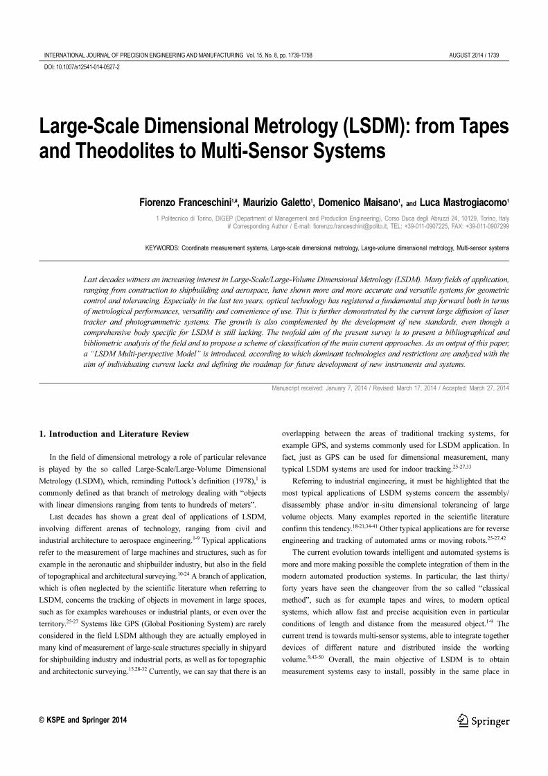
Fig. 1 Evolution of the main families of LSDM systems and relating accuracy over time
1742 / AUGUST 2014 INTERNATIONAL JOURNAL OF PRECISION ENGINEERING AND MANUFACTURING Vol. 15, No. 8
composed by theodolites with added distance measurement capability.83
The advantage of hybrid systems is that they can incorporate all the
advantages of different instruments they integrate. Typical integration
refer to laser scanning and close-range photogrammetry or structured
light, furthermore great advantages can be reached by equipping
automatic systems with video imaging devices. Considering all the
possible combinations, a multitude of different types of hybrid optical-
based measuring systems can be imagined, with their advantages and
drawbacks. An interesting review of traditional and less known optical
techniques is provided by Chen et al. (2000).53,80,84-86
2.10 Looking at the future
Looking at the new generations of systems, the trend of LSDM
seems oriented towards distributed systems, i.e., systems composed by
different typology of devices, (all together) cooperating in order to
pursue the common objective of giving a measurement result as much
as accurate and precise as possible, reliable, repeatable and stable over
time. This is the case, for example, of laser tracker multilateration
systems, and laser trackers and photogrammetry integrated systems.44,86-
89 Recent papers about sensor fusion and data fusion techniques present
an interesting assortment of this kind of application.43,46-48,50,80
A rough scheme about the temporal evolution of the main families
of LSDM systems and relating accuracy is reported in Fig. 1.
3. Analysis Criteria and Methodology Description
Looking at this large variety of LSDM systems, a rational approach
to classify and analyze them from the technological and operational
point of view is mandatory. The paradigm here presented, based on an
in-depth analysis of the recent scientific literature and on the patents
registered in the last thirty years, has the aim of rationalizing and
classifying the large mass of LSDM instruments. A series of taxonomies,
which analyses the various aspects of a LSDM measurement system, is
proposed. A set of five “analysis perspectives” has been identified (see
Table 1). These perspectives rise from the technological and operational
dimensions proposed in the scientific literature for analyzing and
comparing LSDM systems.90
Each perspective is subsequently split in further criteria and/or sub-
criteria of analysis (see Table 2).
The five perspectives allow to analyze the different LSDM
measurement systems both from the technological and the operational
point of view. Similar classifications have been widely proposed in
literature with the aim of providing an overview of the most important
criteria for the selection of measurement processes and for the choice
of the appropriate instrument for a given task.7,18,34,35,90
The peculiarity of the present work is that it provides a set of
taxonomies which give a synoptic inside view of the state of the art and
allow to identify the technological areas that still need to be covered in
order to trace out the possible evolutions for the future. The mainstream
of this approach is based on a detailed analysis of the working
principles of the current measurement systems. It starts with a deep
bibliometric analysis of the whole recent literature and a patent reviews
related to LSDM in order to give an overall view of the current
technologies employed in this field and highlight the zones of major
interest.
The analysis is then extended to other issues such as performances,
working part and environment restrictions, up to the questions related
Table 1 Description of the five perspectives used for the classification and analysis of LSDM systems
Analysis perspectives Description
1 - System organizationThis perspective is related to the physical principles on which the system is based. It comprises the hardwareorganization and the way the system is interfaced to the measured object.
2 - PerformanceThis dimension includes the main metrological and operational characteristics of the system ranging from accuracyto scale width and measuring time.
3 - Working part restrictionsAnalysis of all the main elements characterizing the measured object, which may affect the procedure ofmeasurement and related results.
4 - Environmental restrictionsAnalysis of conditions related to the working environment, which may affect the procedure of measurement andrelated results.
5 - Use conditionsAnalysis of the main elements related to the use of a measurement system: costs, field of application, ergonomics,etc..
Table 2 Criteria of classification and analysis of LSDM systems
Analysisperspectives
Criteria
1 - System1 - organization
1.1 - Dominant technology1.2 - Hardware organization1.3 - Interaction with the measured object1.4 - Measurement principle
2 - Performance
2.1 - Total accuracy (which includes precision2.1 - and trueness)2.2 - Scale size (longest length in the volumetric2.1 - coverage)2.3 - Measurement time (including positioning2.1 - and setup)
3 - Working part1 - restrictions
3.1 - Material3.2 - Surface quality3.3 - Accessibility (location of measured points)
4 - Environmental1 - restrictions
4.1 - Working temperature4.2 - Working humidity4.3 - Working pressure4.4 - Location4.5 - Noise factors
5 - Use conditions
5.1 - Cost5.2 - Supported software5.3 - Standards5.4 - Application fields5.5 - System diffusion5.6 - Technological obsolescence5.7 - Technological complexity5.8 - Ergonomics (easiness of use)

INTERNATIONAL JOURNAL OF PRECISION ENGINEERING AND MANUFACTURING Vol. 15, No. 8 AUGUST 2014 / 1743
to the system employment. For each category the existing systems are
described and potential elements of innovation are highlighted.
As anticipated, the starting point of this survey is the analysis of the
scientific literature in the field of LSDM and the patents registered in
the last thirty years. An in-depth study about the dualism between
articles and patents in LSDM is reported in Franceschini et al. (2014).67
Literature analysis has been conducted basing on Scopus database,
which ensure a large level of coverage and accuracy in the field of
Engineering Science.91-93 A partial limitation of Scopus is that it does
not index books or book chapters but only articles from leading
journals and conference proceedings, which, however, contain the vast
majority of the relevant LSDM publications.
A large number of data referring to the number of both published
articles and citations have been collected and analyzed.94-97
Questel-Orbit has been the reference database for patents, which
integrates patent statistics from more than 95 national and international
patent authorities.66
For both articles and patents, the analysis has been conducted as a
first step through an automatic alphanumeric search on specific keywords
in the field of LSDM and then manually refined by examining title,
abstract and the content of each document.
This procedure for data collection, although being structured and
repeatable, has the main limitation of being not free from the risk of
omitting a portion of LSDM documents. This risk is certainly present
for the literature analysis due to the restrictions of Scopus database, but
is even larger for patents, since their language is sometimes captious
and can complicate the searching by keywords.98,99 Nevertheless the
obtained results provide an interesting framework about the evolution
of LSDM systems over the years and an attractive prospect of the
future trends.
Fig. 2 Temporal distribution of the number of documents (P) and the corresponding citations (C) on the basis of the typology-of-output
classification, Charts are constructed both for articles (charts (1) and (2)) and patents (charts (3) and (4))67
Table 3 Classification of documents and their citations, according to their main topic67
Typology of output DescriptionA - Description of theA - measuring system
Detailed description of a new LSDM system, its technical features, functionality, measurement procedure and(dis)advantages with respect to other systems.
B - New hardwareA - component(s)
Development and characterization of new hardware components, which replace or complement those of an existingmeasuring system, improving its functionality and performance.
C - New application/A - working procedure
Description of novel measurement procedures or applications, aimed at expanding and improving the functionalityand/or performance of an existing measuring system. These procedures/applications generally require additionalexternal hardware equipment.
D - Development of systemA - set-up/calibration
Illustration of a new procedure/algorithm aimed at enhancing the system set-up/calibration stage of an existingmeasuring system.
E - Optimization ofA - measurement operations
Improvement of the efficiency/effectiveness of measurement operations and data management. This optimization istypically software-based and does not imply any change in the measuring system’s hardware or the introduction ofexternal hardware.
F - Performance analysisAnalysis of the performance of an existent measuring system (e.g., evaluation of metrological characteristics, such asrepeatability, accuracy, measurement uncertainty, sampling rate, etc.), based on empirical data or simulations. It mayinclude performance verification according to standards and/or comparison with other measuring systems.
G - Literature review Literature review of the LSDM measuring systems or those based on a specific technology.
1744 / AUGUST 2014 INTERNATIONAL JOURNAL OF PRECISION ENGINEERING AND MANUFACTURING Vol. 15, No. 8
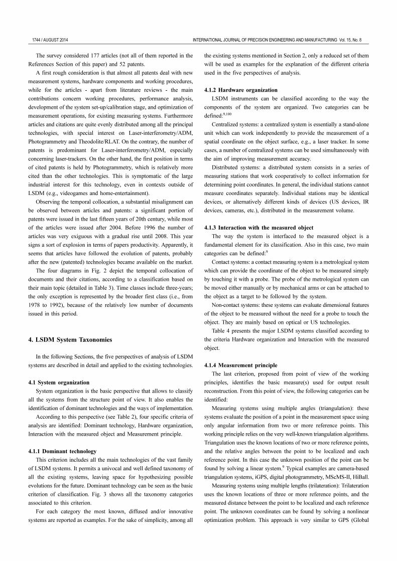
The survey considered 177 articles (not all of them reported in the
References Section of this paper) and 52 patents.
A first rough consideration is that almost all patents deal with new
measurement systems, hardware components and working procedures,
while for the articles - apart from literature reviews - the main
contributions concern working procedures, performance analysis,
development of the system set-up/calibration stage, and optimization of
measurement operations, for existing measuring systems. Furthermore
articles and citations are quite evenly distributed among all the principal
technologies, with special interest on Laser-interferometry/ADM,
Photogrammetry and Theodolite/RLAT. On the contrary, the number of
patents is predominant for Laser-interferometry/ADM, especially
concerning laser-trackers. On the other hand, the first position in terms
of cited patents is held by Photogrammetry, which is relatively more
cited than the other technologies. This is symptomatic of the large
industrial interest for this technology, even in contexts outside of
LSDM (e.g., videogames and home-entertainment).
Observing the temporal collocation, a substantial misalignment can
be observed between articles and patents: a significant portion of
patents were issued in the last fifteen years of 20th century, while most
of the articles were issued after 2004. Before 1996 the number of
articles was very exiguous with a gradual rise until 2008. This year
signs a sort of explosion in terms of papers productivity. Apparently, it
seems that articles have followed the evolution of patents, probably
after the new (patented) technologies became available on the market.
The four diagrams in Fig. 2 depict the temporal collocation of
documents and their citations, according to a classification based on
their main topic (detailed in Table 3). Time classes include three-years;
the only exception is represented by the broader first class (i.e., from
1978 to 1992), because of the relatively low number of documents
issued in this period.
4. LSDM System Taxonomies
In the following Sections, the five perspectives of analysis of LSDM
systems are described in detail and applied to the existing technologies.
4.1 System organization
System organization is the basic perspective that allows to classify
all the systems from the structure point of view. It also enables the
identification of dominant technologies and the ways of implementation.
According to this perspective (see Table 2), four specific criteria of
analysis are identified: Dominant technology, Hardware organization,
Interaction with the measured object and Measurement principle.
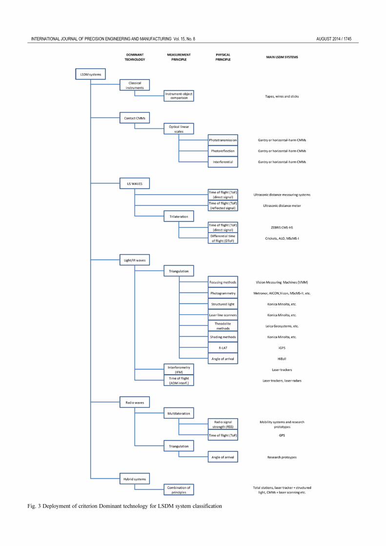
4.1.1 Dominant technology
This criterion includes all the main technologies of the vast family
of LSDM systems. It permits a univocal and well defined taxonomy of
all the existing systems, leaving space for hypothesizing possible
evolutions for the future. Dominant technology can be seen as the basic
criterion of classification. Fig. 3 shows all the taxonomy categories
associated to this criterion.
For each category the most known, diffused and/or innovative
systems are reported as examples. For the sake of simplicity, among all
the existing systems mentioned in Section 2, only a reduced set of them
will be used as examples for the explanation of the different criteria
used in the five perspectives of analysis.
4.1.2 Hardware organization
LSDM instruments can be classified according to the way the
components of the system are organized. Two categories can be
defined:9,100
Centralized systems: a centralized system is essentially a stand-alone
unit which can work independently to provide the measurement of a
spatial coordinate on the object surface, e.g., a laser tracker. In some
cases, a number of centralized systems can be used simultaneously with
the aim of improving measurement accuracy.
Distributed systems: a distributed system consists in a series of
measuring stations that work cooperatively to collect information for
determining point coordinates. In general, the individual stations cannot
measure coordinates separately. Individual stations may be identical
devices, or alternatively different kinds of devices (US devices, IR
devices, cameras, etc.), distributed in the measurement volume.
4.1.3 Interaction with the measured object
The way the system is interfaced to the measured object is a
fundamental element for its classification. Also in this case, two main
categories can be defined:9
Contact systems: a contact measuring system is a metrological system
which can provide the coordinate of the object to be measured simply
by touching it with a probe. The probe of the metrological system can
be moved either manually or by mechanical arms or can be attached to
the object as a target to be followed by the system.
Non-contact systems: these systems can evaluate dimensional features
of the object to be measured without the need for a probe to touch the
object. They are mainly based on optical or US technologies.
Table 4 presents the major LSDM systems classified according to
the criteria Hardware organization and Interaction with the measured
object.
4.1.4 Measurement principle
The last criterion, proposed from point of view of the working
principles, identifies the basic measure(s) used for output result
reconstruction. From this point of view, the following categories can be
identified:
Measuring systems using multiple angles (triangulation): these
systems evaluate the position of a point in the measurement space using
only angular information from two or more reference points. This
working principle relies on the very well-known triangulation algorithms.
Triangulation uses the known locations of two or more reference points,
and the relative angles between the point to be localized and each
reference point. In this case the unknown position of the point can be
found by solving a linear system.9 Typical examples are camera-based
triangulation systems, iGPS, digital photogrammetry, MScMS-II, HiBall.
Measuring systems using multiple lengths (trilateration): Trilateration
uses the known locations of three or more reference points, and the
measured distance between the point to be localized and each reference
point. The unknown coordinates can be found by solving a nonlinear
optimization problem. This approach is very similar to GPS (Global
INTERNATIONAL JOURNAL OF PRECISION ENGINEERING AND MANUFACTURING Vol. 15, No. 8 AUGUST 2014 / 1745
Fig. 3 Deployment of criterion Dominant technology for LSDM system classification
1746 / AUGUST 2014 INTERNATIONAL JOURNAL OF PRECISION ENGINEERING AND MANUFACTURING Vol. 15, No. 8
Positioning System) localisation principle.101 Systems based on this
working principle are multiple laser interferometers, multiple ADM
systems, MScMS-I.
Measuring systems using two angles and one length: Most of the
Large-Scale measuring systems rely on the determination of one length
and two angles. These systems are also called Spherical Coordinate
Measurement Systems because the initial coordinates of a point are
evaluated in a spherical coordinate system. Generally, the angles are
measured by means of angular encoders, whilst the range measurement
can be performed using either IFM or ADM technology. The spherical
coordinates are then easily transformed in Cartesian coordinates by a
central processing unit that is able to derive the object features from the
measured points in the 3D space. Examples of these systems are laser
trackers, laser radars and total stations.
4.2 Performance
The second perspective considered is that of Performance, which
considers LSDM major metrological and operational features.
According to this perspective (see Table 2), three criteria of analysis
are identified: Total accuracy (which includes precision and trueness),
Scale size (longest length in the volumetric coverage) and Measurement
time (including positioning and setup).
4.2.1 Total accuracy
This criterion, associated with the second one (Scale size) is of basic
importance for defining the level of performance of a LSDM system.
Usually these two criteria fall in conflict, due to the intrinsic nature of
the dimensional measuring instruments for which, enlarging the extension
of the measurand, the related accuracy tends to increase.
The metrological performance of a measuring system is usually
tested through the use of specific indicators, generally prescribed by
international standards (see Table 5).
Every measuring system can be characterized by evaluating these
parameters. In general, when dealing with coordinate measurement
systems, performance evaluation refers to the assessment of accuracy,
repeatability and reproducibility of the measurement performed in a
well-defined point (or portion of volume) in the whole measurement
domain of the system. These three performance indicators are enough
to indicate locally the quality of a measurement. Furthermore,
uncertainty estimation refers to the evaluation of the dispersion
associated with measured data and related measuring procedure. This
gives an overall indication of the behaviour of the system in the whole
space of measurement when a specific measuring procedure is applied.
4.2.2 Scale size
Scale size is the criterion that makes the difference between
traditional dimensional metrology instruments and LSDM ones. The
primary purpose of LSDM is the three-dimensional measurement of
large-sized objects. The applications for measurement and control of
mechanical structures and machines require very high levels of accuracy.
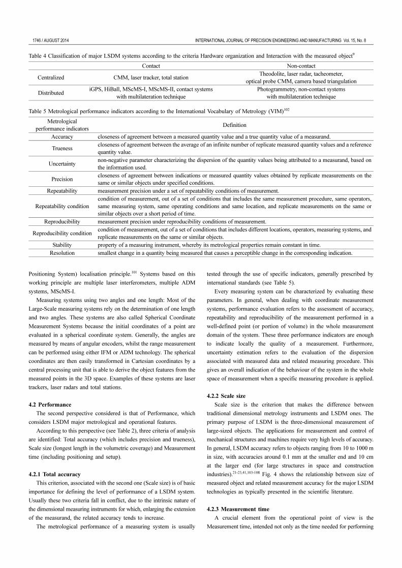
In general, LSDM accuracy refers to objects ranging from 10 to 1000 m
in size, with accuracies around 0.1 mm at the smaller end and 10 cm
at the larger end (for large structures in space and construction
industries).21-23,41,103-108 Fig. 4 shows the relationship between size of
measured object and related measurement accuracy for the major LSDM
technologies as typically presented in the scientific literature.
4.2.3 Measurement time
A crucial element from the operational point of view is the
Measurement time, intended not only as the time needed for performing
Table 4 Classification of major LSDM systems according to the criteria Hardware organization and Interaction with the measured object9
Contact Non-contact
Centralized CMM, laser tracker, total stationTheodolite, laser radar, tacheometer,
optical probe CMM, camera based triangulation
DistributediGPS, HiBall, MScMS-I, MScMS-II, contact systems
with multilateration techniquePhotogrammetry, non-contact systems
with multilateration technique
Table 5 Metrological performance indicators according to the International Vocabulary of Metrology (VIM)102
Metrologicalperformance indicators
Definition
Accuracy closeness of agreement between a measured quantity value and a true quantity value of a measurand.
Truenesscloseness of agreement between the average of an infinite number of replicate measured quantity values and a referencequantity value.
Uncertaintynon-negative parameter characterizing the dispersion of the quantity values being attributed to a measurand, based onthe information used.
Precisioncloseness of agreement between indications or measured quantity values obtained by replicate measurements on thesame or similar objects under specified conditions.
Repeatability measurement precision under a set of repeatability conditions of measurement.
Repeatability conditioncondition of measurement, out of a set of conditions that includes the same measurement procedure, same operators,same measuring system, same operating conditions and same location, and replicate measurements on the same orsimilar objects over a short period of time.
Reproducibility measurement precision under reproducibility conditions of measurement.
Reproducibility conditioncondition of measurement, out of a set of conditions that includes different locations, operators, measuring systems, andreplicate measurements on the same or similar objects.
Stability property of a measuring instrument, whereby its metrological properties remain constant in time.Resolution smallest change in a quantity being measured that causes a perceptible change in the corresponding indication.
INTERNATIONAL JOURNAL OF PRECISION ENGINEERING AND MANUFACTURING Vol. 15, No. 8 AUGUST 2014 / 1747
a single measurement, but all the time necessary for the management
of the instrument, including positioning and setup. For that reason many
systems that, in principle, may generate a certain interest for their
elevated metrological performances, often produce deep disappointment
because of their long worm-up times. This is the case, for example, of
past generation laser trackers.6,7,87,110 Other systems, even if they do not
guarantee excellent levels of accuracy, are often preferred for their lower
times of use and setup. Examples are photogrammetric systems and
iGPS.59,77,79 Table 6 reports a classification of the major LSDM systems
according to their related Measurement times.
4.3 Working part restrictions
Together with Environmental restrictions, Working part restrictions
is the basic perspective directly related to the working conditions. In
fact though many systems present excellent metrological characteristics,
they may show severe limits of application related to the measured
object material and its surface finishing. For example, contact systems
cannot be employed with soft or flexible surfaces. In some other cases,
such as for example with many optical systems, the surface of the
measured object must be opportunely treated with specific paints or
covering in order to avoid reflections which may influence the
measurement results.111
Another critical issue is the presence of holes, undercuts or internal
zones. These features cannot be easily measured by all the systems, for
example the optical ones show great problems in this kind of
applications.112
With reference to this perspective, three criteria of analysis are
identified: Material, Surface quality, Accessibility (location of measured
points) (see Table 7).
4.3.1 Material
This criterion refers to the mechanical properties of the measured
object material. Considering that, during the measuring procedure, a
Fig. 4 Relationship between object size and accuracy for different LSDM technologies9,109 (with permission)
Table 6 Classification of major LSDM systems according to the criterion Measurement time
Time Positioning and setup Calibration Measurement
MinutesTheodolites, photogrammetric systems,
MScMS-II, iGPSTheodolites, photogrammetric systems,
MScMS-II, iGPS
Laser trackers, theodolites,photogrammetric systems,
MScMS-II, iGPSHours Laser trackers total stations, HiBall, MScMS-I Laser trackers total stations, HiBall, MScMS-I CMM (gantry or horizontal-arm)Days CMM (gantry or horizontal-arm) CMM (gantry or horizontal-arm)
Table 7 Criteria and element of evaluation for the perspective Working
part restrictions
Criterion Element of evaluation
4.3.1 - Material
- rigid solid- soft/flexible solid- liquid- gas
4.3.2 - Surface quality
- smooth- rough- matt- reflective- translucent- transparent- pre-treated
4.3.3- Accessibility- (location of- measured points)
- line of sight- hidden points (hols, undercuts,- internal zones)
1748 / AUGUST 2014 INTERNATIONAL JOURNAL OF PRECISION ENGINEERING AND MANUFACTURING Vol. 15, No. 8
probe or the measuring system itself must be brought into contact with
the measured object, or a ray or a radio/US frequency must be reflected
by its surface, the nature of the material may strongly affect the result
of the measurement.107,113-116
According to this criterion, four levels of evaluation may be
identified: rigid solid, soft/flexible solid, liquid, gas.
All contact systems are automatically excluded in case of soft/flexible
solid, liquid and gas materials. Hence, for example, iGPS, which is
usually considered a very accurate and versatile system, cannot be used
for the measurement of liquid surfaces in tanks.117,118 On the contrary,
US systems may be used for measuring the change of density or
temperature in air or for flow analysis.119 Hence, they can be very helpful
for mapping environment gradients in a given volume or space.
4.3.2 Surface quality
Surface quality concerns the level of finishing of the surface of the
measured object. Usually, both for contact and non-contact system, rough
surface finishing may compromise the whole measurement process, but
for optical instrument this issue is even more critical. In fact, even
when using contact optical systems, such as for example MScMS-II,
surface reflections of light (or IR signal) may interfere with the
measurement.9,65 This is the reason why, very often, optical systems need
matt surfaces or specific pre-treatments of them before measurement.111
Furthermore, surface quality depends on the type of material considered.
Smooth metal surfaces, reflective or transparent material are the most
critical for optical systems.13
Seven element of evaluation may be identified: smooth, rough, matt,
reflective, translucent, transparent, pre-treated. In particular, with the
term pre-treated, it is intended that a surface must necessarily be treated
in order to be measured by a given instrument.
4.3.3 Accessibility
This last criterion is related to the possibility of measuring holes,
undercuts or internal zones. This is often a critical drawback for optical
systems, which work well only if the measured points are positioned in
line of sight with respect to the sensors.
According to this criterion, two element of discrimination can be
defined: line of sight, hidden points (hols, undercuts, internal zones).
Usually, most of the LSDM systems need a direct line of sight
between sensors and measured point, however, the use of specific
probes may help to overcome the problem of measuring small holes
and cavities. This is the case, for example, of CMMs and MScMS-II or
specific optical systems.65,81,112
On the contrary, it must be highlighted that in case of distributed
systems, such as for example iGPS, MScMS-I, MScMS-II or
photogrammetry, only a subset of sensors must be on the line of sight
of the measured object, and this represents the major potential of this
kind of systems.63-65,77
4.4 Environmental restrictions
Environmental restrictions are strictly connected to the specific field
of application. They define the environmental conditions in which the
system may be employed. This perspective, for example, considers if
a system can be used indoor or outdoor, or if it is suitable for non-
standard conditions of temperature, humidity, contamination, etc.120-122
According to this perspective, five criteria of analysis are defined:
Working temperature, Working humidity, Working pressure, Location
and Noise factors (see Table 8).
4.4.1,2,3 Working temperature, working humidity and working
pressure
These three criteria refer to the typical variables of influence during
measurement. All the most diffused systems for LSDM (see Table 4)
are designed for standard conditions. That means that they should be
used with caution out of these limits. This is one of the main drawbacks
of these systems for their employment out of laboratories. In the
scientific literature, approaches for special applications, such as for
example underwater measurements or similar, are often discussed.120-123
For each of these criteria, three element of discrimination can be
defined: under standard values, in standard values, over standard values.
4.4.4 Location
Location explicitly defines if a given system may be used indoor or
outdoor. This criterion sums up all the implications related to the
employment of the system in the various environmental conditions. Due
to their principal laboratory application, all the main systems for LSDM
here considered are designed for indoor applications, except for same rare
cases, in which external conditions are therefore kept under strict control.
Nevertheless, there are some example of outdoor applications, especially
for surveying big mechanical structures, aerospace, construction,
architectural and archaeological applications.1,15,23,29,30,32,105,116
4.4.5 Noise factors
Noise factors is a criterion which is worth discussing accurately. It
includes all that factors, which may affect the result of a measurement.
According to the dominant technology criterion, each system may be
more or less sensitive to one or more disturbing elements. A non-
exhaustive list of noise factors involves (see Table 8): vibrations, air
turbulence, sonic interference, ambient lighting, absence of atmosphere,
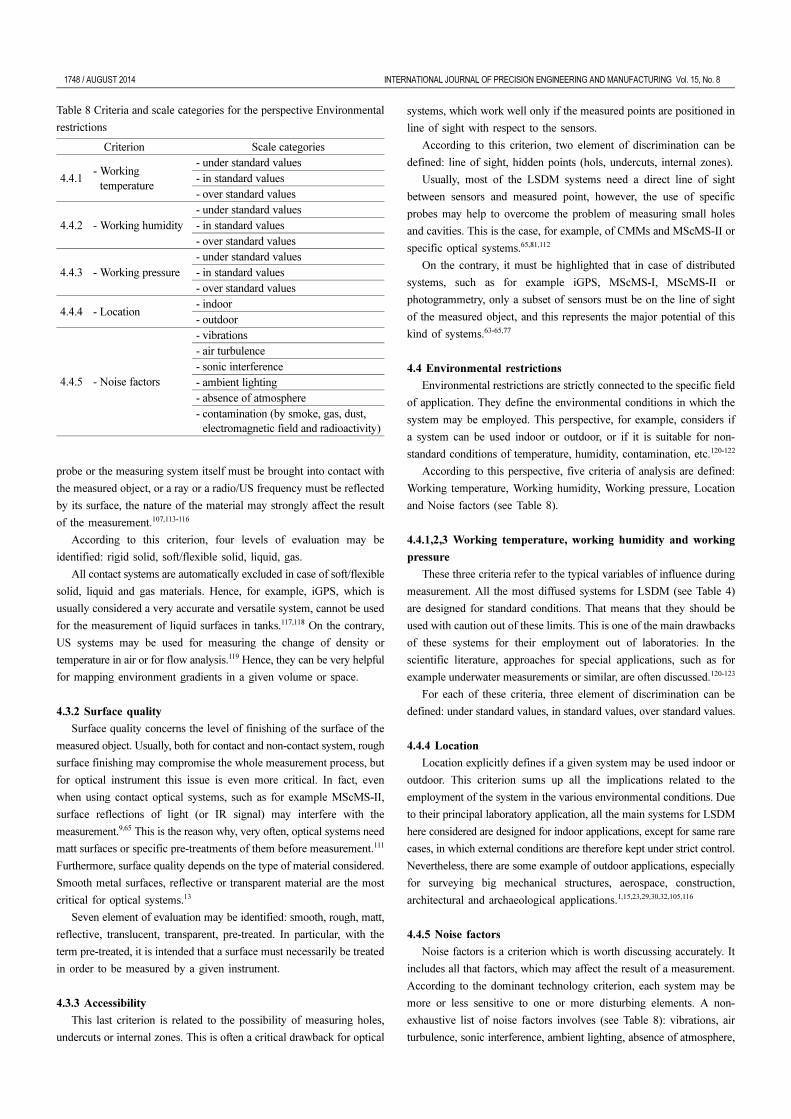
Table 8 Criteria and scale categories for the perspective Environmental
restrictions
Criterion Scale categories
4.4.1- Working- temperature
- under standard values- in standard values- over standard values
4.4.2 - Working humidity- under standard values- in standard values- over standard values
4.4.3 - Working pressure- under standard values- in standard values- over standard values
4.4.4 - Location- indoor- outdoor
4.4.5 - Noise factors
- vibrations- air turbulence- sonic interference- ambient lighting- absence of atmosphere- contamination (by smoke, gas, dust,- electromagnetic field and radioactivity)
INTERNATIONAL JOURNAL OF PRECISION ENGINEERING AND MANUFACTURING Vol. 15, No. 8 AUGUST 2014 / 1749
contamination (by smoke, gas, dust, electromagnetic field and
radioactivity).
For example, systems based on US waves are very sensitive to sonic
interference; on the contrary, systems using light/IR waves suffer ambient
lighting. Many studies showed that optical systems, as well as sonic
ones, are strongly affected by air turbulence and unevenness.9,124 Also
dust contamination is the Achille’s heel of the large part of the most
diffused systems.
4.5 Use conditions
Use conditions is the perspective which includes all the elements
related to the procurement and application of the system. Eight elements
of discrimination are defined (see Table 9): Cost, Supported software,
Standards, Application fields, System diffusion, Technological
obsolescence, Technological complexity, Ergonomics (easiness of use).
4.5.1 Cost
Cost is one of the basic criteria, as well as the metrological
performance, in the choice between two or more LSDM systems.7,34,35,90
Even if it includes cost of acquisition and maintenance, it must be said
that the cost of acquisition is the most significant and, in many cases,
reaches hundreds of thousands of Euros.
Table 10 reports a classification of the most diffused optical LSDM
systems on the bases of Costs, Total accuracy (discussed in Section
4.2.1) and Ergonomics (discussed in Section 4.5.8).
4.5.2 Supported software
The basic information that a LSDM system may provide is either
the Cartesian coordinates of a measured point or the measure of a
geometrical feature (i.e. a distance or an angle).1,8,9 However, many
system are equipped by specific software for data elaboration, in order
to provide further information such as for example the features of
specific geometrical figures, or to perform advanced calibration, set-up
and self-diagnostic operations.125-131
Furthermore, the possibility to interact with other systems,
instruments or external software, is an important key-element for the use
in factories and laboratories.19,37,132-134 In many practical applications,
collected measurements are used for the verification of geometrical
tolerances, reverse engineering, surfaces analysis, etc. The interface with
specific CAD software is mandatory for these applications.135
Basic elements to deploy this criterion are: GUI (Graphic User
Interface), coordinate measurement, basic geometric measurements
(distances, geometrical figures, etc.), tolerance verification, evaluation
of measurement uncertainty, self-calibration, self-diagnostic, self-
detection, self-compensation and self-correction of errors, compatibility
with other software (CAD, CAE, etc.).
4.5.3 Standards
In the field of LSDM there is still a considerable lack of standards.
The reasons are both related to the heterogeneity of instruments and to
the fact that these last years have seen a massive introduction of new
systems based on optical technology.8
Actually, the main reference standards for LSDM are related to
CMMs or, in general, to systems for dimensional measurements136-140
or to optical systems.141,142 However, the arising interest towards LSDM
in the last ten years is attested by the development of some specific
standards, such as for example, ASME B89.4.19:2006 for laser trackers
and the German guideline VDI/VDE 2634:2002 for photogrammetry.
Referring to the current scientific literature, many papers try to give
indications and prescription for system evaluation, calibration, traceability
and uncertainty evaluation. For this last case, the reference standard is
the “Guide to the expression of uncertainty in measurement”.64,109,124,130,
143-154
In detail, six elements are considered for the analysis: construction,
setup, use and storage, calibration, uncertainty evaluation, error correction/
compensation.
4.5.4 Application fields
Application field is another important element of distinction for
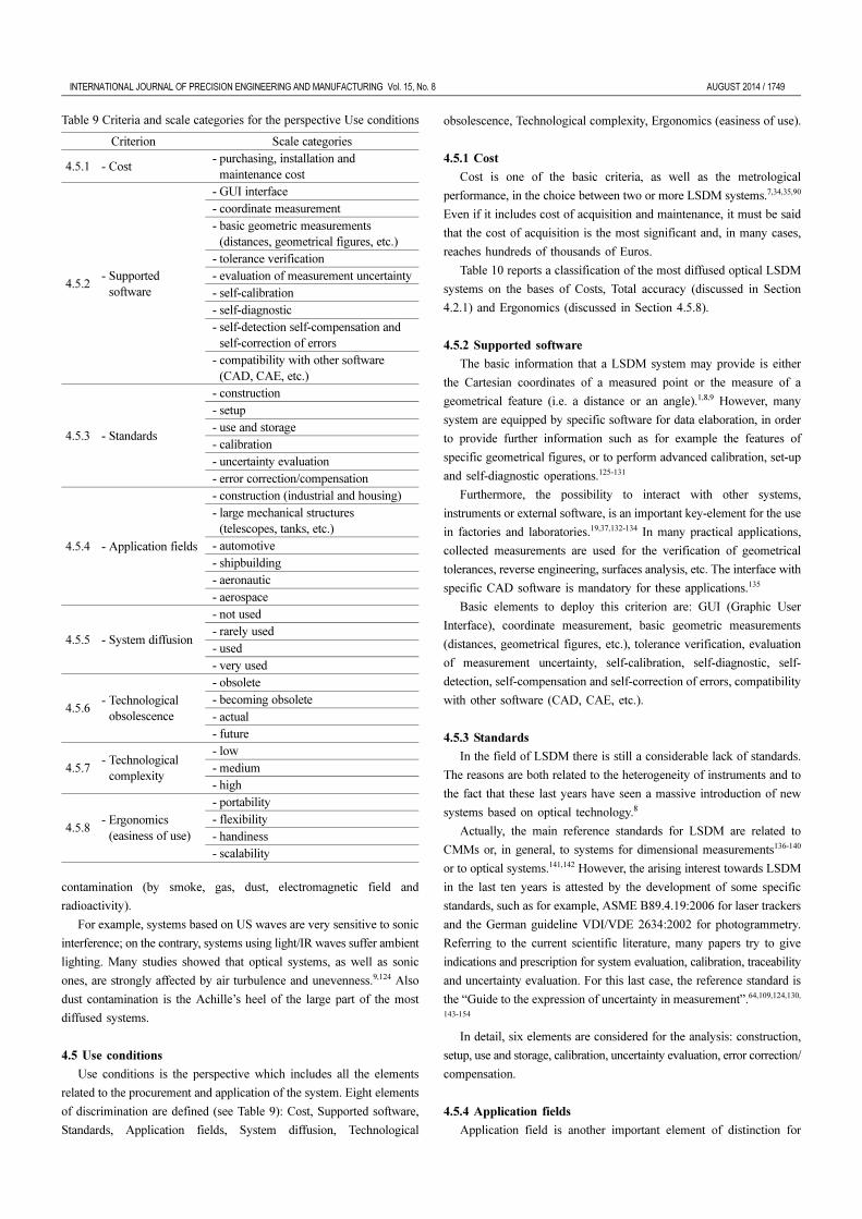
Table 9 Criteria and scale categories for the perspective Use conditions
Criterion Scale categories
4.5.1 - Cost- purchasing, installation and- maintenance cost
4.5.2- Supported- software
- GUI interface- coordinate measurement- basic geometric measurements- (distances, geometrical figures, etc.)- tolerance verification- evaluation of measurement uncertainty- self-calibration- self-diagnostic- self-detection self-compensation and- self-correction of errors- compatibility with other software- (CAD, CAE, etc.)
4.5.3 - Standards
- construction- setup- use and storage- calibration- uncertainty evaluation- error correction/compensation
4.5.4 - Application fields
- construction (industrial and housing)- large mechanical structures- (telescopes, tanks, etc.)- automotive- shipbuilding- aeronautic- aerospace
4.5.5 - System diffusion
- not used- rarely used- used- very used
4.5.6- Technological- obsolescence
- obsolete- becoming obsolete- actual- future
4.5.7- Technological- complexity
- low- medium- high
4.5.8- Ergonomics- (easiness of use)
- portability- flexibility- handiness- scalability
1750 / AUGUST 2014 INTERNATIONAL JOURNAL OF PRECISION ENGINEERING AND MANUFACTURING Vol. 15, No. 8
LSDM systems. As highlighted in the previous Sections, application
fields range from archaeology to aerospace. In many cases, the versatility
implies the possibility of using the system in different environmental
conditions. The main application fields for LSDM systems are:
construction (industrial and housing), large mechanical structures
(telescopes, tanks, etc.), automotive, shipbuilding, aeronautic, aerospace.
4.5.5 System diffusion
This criterion is related to the diffusion of technologies. Many
systems, although technologically advanced and with high metrological
performance, are not so diffused as expected. Sometimes the reasons
must be found in other criteria such as for example Cost, Ergonomics,
etc., which must be better investigated and deepened. Scale categories
of this criterion are: not used, rarely used, used, very used. The major
LSDM systems are classified in Table 11 according to this criterion as
well as Technological obsolescence.
4.5.6 Technological obsolescence
Technological obsolescence is a criterion useful to indicate the
ageing of a technology. Usually the Technological obsolescence is also
associated to low metrological performance, complexity in use and poor
interfacing with other automatic systems. Scale categories are: obsolete,
becoming obsolete, actual, future.
As an example, Table 11 presents the major LSDM systems
classified according to the criteria System diffusion and Technological
obsolescence.
4.5.7 Technological complexity
Technological complexity is a criterion considered in the choice of
a system. This is also correlated to the complexity of use and the
versatility. A system can be defined as technological complex if it is
made up of multiple technologically advanced components, which
interact with each other and with other systems. Even if this condition
might mean high and innovative performance, it often may imply a
reduction of reliability, difficulty in repair and maintenance, complexity
in set-up and use. In this way, often high technological components
may result in source of troubles during system application. In the
present analysis the concept of Technological complexity is intended in
this negative acceptation. Scale categories are: high, medium, low.
4.5.8 Ergonomics (easiness of use)
This criterion is directly related to the easiness of use. It may entail
specific training of the operator.
In particular, Ergonomics includes:65,81
portability: it is intended as the capability of the system to be easily
moved within the working environment;
flexibility: it refers to system capabilities to apply to different
working environments and to perform various measurement tasks;
handiness: it means easiness of installation and use;
scalability: it refers to the capability to cover differently sized and
shaped volumes.
Table 10 reports a classification of the most diffused optical LSDM
systems on the basis of Ergonomics, as well as Costs (discussed in
Section 4.5.1) and Total accuracy.
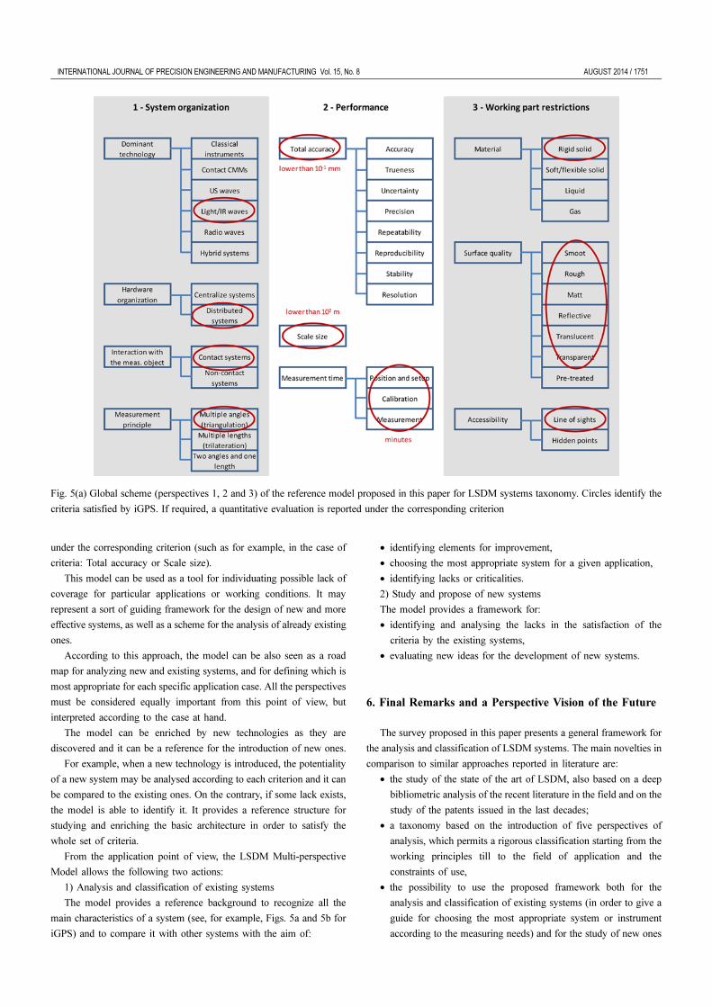
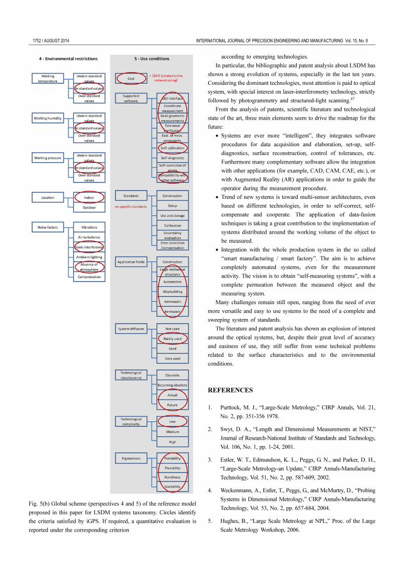
5. Using the LSDM Multi-perspective Model
The global reference model (LSDM Multi-perspective Model)
proposed in this paper is synthetized in Figs. 5(a) and 5(b) with an
example of application to iGPS. All the five perspectives are deployed
into their resultant criteria, and the system is analyzed according to
each of them. Circles drawn in Figs. 5(a) and 5(b) identify the criteria
satisfied by the system. If required, a quantitative evaluation is reported
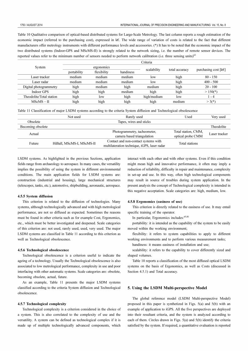
Table 10 Qualitative comparison of optical-based distributed systems for Large-Scale Metrology. The last column reports a rough estimation of the
economic impact (referred to the purchasing cost), expressed in k€. The wide range of variation of costs is related to the fact that different
manufacturers offer metrology instruments with different performance levels and accessories. (*) It has to be noted that the economic impact of the
two distributed systems (Indoor-GPS and MScMS-II) is strongly related to the network sizing, i.e. the number of remote sensor devices. The
reported values refer to the minimum number of sensors needed to perform network calibration (i.e. three sensing units)63
SystemCriteria
ergonomicsscalability total accuracy purchasing cost [k€]
portability flexibility handinessLaser tracker medium medium medium low high 80 - 150Laser radar medium medium medium low high 400 - 500
Digital photogrammetry high medium high medium high 20 - 100Indoor GPS high high medium high high > 150(*)
Theodolite/Total station high low high high/medium low 1 - 4MScMS – II high high high high medium > 3(*)
Table 11 Classification of major LSDM systems according to the criteria System diffusion and Technological obsolescence
Not used Rarely used Used Very usedObsolete Tapes, wires and sticks
Becoming obsolete Theodolite
ActualPhotogrammetry, tacheometer,
camera based triangulationTotal station, CMM,optical probe CMM
Laser tracker
Future HiBall, MScMS-I, MScMS-IIContact and non-contact systems with
multilateration technique, iGPS, laser radarTotal stations
INTERNATIONAL JOURNAL OF PRECISION ENGINEERING AND MANUFACTURING Vol. 15, No. 8 AUGUST 2014 / 1751
under the corresponding criterion (such as for example, in the case of
criteria: Total accuracy or Scale size).
This model can be used as a tool for individuating possible lack of
coverage for particular applications or working conditions. It may
represent a sort of guiding framework for the design of new and more
effective systems, as well as a scheme for the analysis of already existing
ones.
According to this approach, the model can be also seen as a road
map for analyzing new and existing systems, and for defining which is
most appropriate for each specific application case. All the perspectives
must be considered equally important from this point of view, but
interpreted according to the case at hand.
The model can be enriched by new technologies as they are
discovered and it can be a reference for the introduction of new ones.
For example, when a new technology is introduced, the potentiality
of a new system may be analysed according to each criterion and it can
be compared to the existing ones. On the contrary, if some lack exists,
the model is able to identify it. It provides a reference structure for
studying and enriching the basic architecture in order to satisfy the
whole set of criteria.
From the application point of view, the LSDM Multi-perspective
Model allows the following two actions:
1) Analysis and classification of existing systems
The model provides a reference background to recognize all the
main characteristics of a system (see, for example, Figs. 5a and 5b for
iGPS) and to compare it with other systems with the aim of:
• identifying elements for improvement,
• choosing the most appropriate system for a given application,
• identifying lacks or criticalities.
2) Study and propose of new systems
The model provides a framework for:
• identifying and analysing the lacks in the satisfaction of the
criteria by the existing systems,
• evaluating new ideas for the development of new systems.
6. Final Remarks and a Perspective Vision of the Future
The survey proposed in this paper presents a general framework for
the analysis and classification of LSDM systems. The main novelties in
comparison to similar approaches reported in literature are:
• the study of the state of the art of LSDM, also based on a deep
bibliometric analysis of the recent literature in the field and on the
study of the patents issued in the last decades;
• a taxonomy based on the introduction of five perspectives of
analysis, which permits a rigorous classification starting from the
working principles till to the field of application and the
constraints of use,
• the possibility to use the proposed framework both for the
analysis and classification of existing systems (in order to give a
guide for choosing the most appropriate system or instrument
according to the measuring needs) and for the study of new ones
Fig. 5(a) Global scheme (perspectives 1, 2 and 3) of the reference model proposed in this paper for LSDM systems taxonomy. Circles identify the
criteria satisfied by iGPS. If required, a quantitative evaluation is reported under the corresponding criterion
1752 / AUGUST 2014 INTERNATIONAL JOURNAL OF PRECISION ENGINEERING AND MANUFACTURING Vol. 15, No. 8
according to emerging technologies.
In particular, the bibliographic and patent analysis about LSDM has
shown a strong evolution of systems, especially in the last ten years.
Considering the dominant technologies, most attention is paid to optical
system, with special interest on laser-interferometry technology, strictly
followed by photogrammetry and structured-light scanning.67
From the analysis of patents, scientific literature and technological
state of the art, three main elements seem to drive the roadmap for the
future:
• Systems are ever more “intelligent”, they integrates software
procedures for data acquisition and elaboration, set-up, self-
diagnostics, surface reconstruction, control of tolerances, etc.
Furthermore many complementary software allow the integration
with other applications (for example, CAD, CAM, CAE, etc.), or
with Augmented Reality (AR) applications in order to guide the
operator during the measurement procedure.
• Trend of new systems is toward multi-sensor architectures, even
based on different technologies, in order to self-correct, self-
compensate and cooperate. The application of data-fusion
techniques is taking a great contribution to the implementation of
systems distributed around the working volume of the object to
be measured.
• Integration with the whole production system in the so called
“smart manufacturing / smart factory”. The aim is to achieve
completely automated systems, even for the measurement
activity. The vision is to obtain “self-measuring systems”, with a
complete permeation between the measured object and the
measuring system.
Many challenges remain still open, ranging from the need of ever
more versatile and easy to use systems to the need of a complete and
sweeping system of standards.
The literature and patent analysis has shown an explosion of interest
around the optical systems, but, despite their great level of accuracy
and easiness of use, they still suffer from some technical problems
related to the surface characteristics and to the environmental
conditions.
REFERENCES
1. Purttock, M. J., “Large-Scale Metrology,” CIRP Annals, Vol. 21,
No. 2, pp. 351-356 1978.
2. Swyt, D. A., “Length and Dimensional Measurements at NIST,”
Journal of Research-National Institute of Standards and Technology,
Vol. 106, No. 1, pp. 1-24, 2001.
3. Estler, W. T., Edmundson, K. L., Peggs, G. N., and Parker, D. H.,
“Large-Scale Metrology-an Update,” CIRP Annals-Manufacturing
Technology, Vol. 51, No. 2, pp. 587-609, 2002.
4. Weckenmann, A., Estler, T., Peggs, G., and McMurtry, D., “Probing
Systems in Dimensional Metrology,” CIRP Annals-Manufacturing
Technology, Vol. 53, No. 2, pp. 657-684, 2004.
5. Hughes, B., “Large Scale Metrology at NPL,” Proc. of the Large
Scale Metrology Workshop, 2006.
Fig. 5(b) Global scheme (perspectives 4 and 5) of the reference model
proposed in this paper for LSDM systems taxonomy. Circles identify
the criteria satisfied by iGPS. If required, a quantitative evaluation is
reported under the corresponding criterion
INTERNATIONAL JOURNAL OF PRECISION ENGINEERING AND MANUFACTURING Vol. 15, No. 8 AUGUST 2014 / 1753
6. Cuypers, W., Van Gestel, N., Voet, A., Kruth, J. P., Mingneau, J.,
and Bleys, P., “Optical Measurement Techniques for Mobile and
Large-Scale Dimensional Metrology,” Optics and Lasers in
Engineering, Vol. 47, No. 3-4, pp. 292-300, 2009.
7. Cuypers, W., Van Gestel, N., Voet, A., Kruth, J. P., Mingneau, J.,
and Bleys, P., “Optical Measurement Techniques for Mobile and
Large-Scale Dimensional Metrology,” Optics and Lasers in
Engineering, Vol. 47, No. 3, pp. 292-300, 2009.
8. Peggs, G., Maropoulos, P. G., Hughes, E., Forbes, A., Robson, S.,
Ziebart, M., and Muralikrishnan, B., “Recent Developments in
Large-Scale Dimensional Metrology,” Proceedings of the Institution
of Mechanical Engineers, Part B: Journal of Engineering
Manufacture, Vol. 223, No. 6, pp. 571-595, 2009.
9. Franceschini, F., Galetto, M., Maisano, D., Mastrogiacomo, L., and
Pralio, B., “Distributed Large-Scale Dimensional Metrology,”
Springer, 2011.
10. Burner, A. W., Radeztsky, R. H., and Liu, T., “Videometric
Applications in Wind Tunnels,” Proc. of SPIE, Vol. 3174, pp. 234-
247, 1997.
11. Kugel, H. W., Loesser, D., Roquemore, A. L., Menon, M. M., and
Barry, R. E., “Precision Metrology of NSTX Surfaces using
Coherent Laser Radar Ranging,” Review of Scientific Instruments,
Vol. 72, No. 1, pp. 533-536, 2001.
12. Jones, T. W. and Pappa, R. S., “Dot Projection Photogrammetric
Technique for Shape Measurements of Aerospace Test Articles,”
Proc. of 40th AIAA Aplied Aerodynamics Conference, AIAA
2002-0532, 2002.
13. Jones, T. W., Dorrington, A. A., Brittman, P. L., and Danehy, P. M.,
“Laser Induced Fluorescence for Photogrammetric Measurement of
Transparent or Reflective Aerospace Structures,” Proc. of 49th
Annual International Instrumentation Symposium, 2003.
14. Scopigno, R., Cignoni, P., Callieri, M., Ganovelli, F., Impoco, G., et
al., “Using Optically Scanned 3D Data in the Restoration of
Michelangelo's David,” Proc. of SPIE, Vol. 5146, pp. 44-53, 2003.
15. Balsamo, A., Chimienti, A., Desogus, S., Grattoni, P., Meda, A., et
al., “A Portable Stereovision System for Cultural Heritage
Monitoring,” CIRP Annals-Manufacturing Technology, Vol. 54,
No. 1, pp. 499-502, 2005.
16. Hand, S. D., Clark, J. F. F., Mongon, W. J., and Schindelholz, E.,
“Measurement of the USS Monitor Propeller using Structured Light
and Coherent Laser Radar Scanning Technologies,” Proc. of the
CMSC 2005 Coordinate Systems Measurement Conference, 2005.
17. Reichold, A., Dawson, M., Green, J., Han, Y., Jones, M., et al., “The
LiCAS-RTRS-A Rapid and Cost Efficient Survey System for the
ILC,” Proc. of the 9th International Workshop on Accelerator
Alignment, 2006.
18. Cai, B., Guo, Y., Jamshidi, J., and Maropoulos, P., “Measurability
Analysis Of Large Volume Metrology Process Model For Early
Design,” Proc. of 5th International Conference on Digital Enterprise
Technology, 2008.
19. Maropoulos, P. G., Guo, Y., Jamshidi, J., and Cai, B., “Large
Volume Metrology Process Models: A Framework for Integrating
Measurement with Assembly Planning,” CIRP Annals-
Manufacturing Technology, Vol. 57, No. 1, pp. 477-480, 2008.
20. Jamshidi, J., Kayani, A., Iravani, P., Maropoulos, P. G., and
Summers, M., “Manufacturing and Assembly Automation by
Integrated Metrology Systems for Aircraft Wing Fabrication,” Proc.
of the Institution of Mechanical Engineers, Part B: Journal of
Engineering Manufacture, Vol. 224, No. 1, pp. 25-36, 2010.
21. Cuesta, E., Álvarez, B. J., Sánchez-Lasheras, F., Fernández, R. L.,
and Gonzalez-Madruga, D., “Feasibility Evaluation of
Photogrammetry versus Coordinate Measuring Arms for the
Assembly of Welded Structures,” Advanced Materials Research,
Vol. 498, pp. 103-108, 2012.
22. Flynn, R., “Synthesizing Metrology Technologies to Reduce
Engineering Time for Large CNC Machine Compensation,” SAE
International Journal of Materials and Manufacturing, Vol. 5, No.
1, pp. 49-59, 2011.
23. Goch, G., Knapp, W., and Härtig, F., “Precision Engineering for
Wind Energy Systems,” CIRP Annals-Manufacturing Technology,
Vol. 61, No. 2, pp. 611-634, 2012.
24. Liu, T., Burner, A. W., Jones, T. W., and Barrows, D. A.,
“Photogrammetric Techniques for Aerospace Applications,”
Progress in Aerospace Sciences, Vol. 54, pp. 1-58, 2012.
25. Nüchter, A., Surmann, H., Lingemann, K., and Hertzberg, J.,
“Consistent 3D Model Construction with Autonomous Mobile
Robots,” Advances in Artificial Intelligence, vol. 2821, pp. 550-
564, 2003.
26. Galetto, M., Mastrogiacomo, L., Pralio, B., and Spagnolo, C.,
“Indoor Environmental Mapping by Means of Autonomous Guided
Agents,” Proc. of ASME 2010 10th Biennial Conference on
Engineering Systems Design and Analysis, Paper No. ESDA2010-
25224, pp. 759-767, 2010.
27. Santolaria, J., Conte, J., and Ginés, M., “Laser Tracker-Based
Kinematic Parameter Calibration of Industrial Robots by Improved
CPA Method and Active Retroreflector,” The International Journal
of Advanced Manufacturing Technology, Vol. 66, No. 9-12, pp.
2087-2106, 2013.
28. Taylor, J., Beraldin, J.-A., Godin, G., Cournoyer, L., Baribeau, R.,
et al., “NRC 3D Imaging Technology for Museum and Heritage
Applications,” The Journal of Visualization and Computer
Animation, Vol. 14, No. 3, pp. 121-138, 2003.
29. Blais, F. and Beraldin, J.-A., “Recent Developments in 3D Multi-
Modal Laser Imaging Applied to Cultural Heritage,” Machine
Vision and Applications, Vol. 17, No. 6, pp. 395-409, 2006.
30. Guidi, G., Frischer, B., Russo, M., Spinetti, A., Carosso, L., and
Micoli, L. L., “Three-Dimensional Acquisition of Large and Detailed
Cultural Heritage Objects,” Machine Vision and Applications, Vol.
1754 / AUGUST 2014 INTERNATIONAL JOURNAL OF PRECISION ENGINEERING AND MANUFACTURING Vol. 15, No. 8
17, no. 6, pp. 349-360, 2006.
31. Atwater, F., Hand, D., Hardin, H., Edwards, W., and Chamsine, G.,
“The Measurement and Modeling of a World War I Mark IV Tank
Using CLR and CCD Camera/Line Scanning Systems in an Outside
Environment,” Journal of the CMSC, Vol. 2, No. 2, pp. 4-10, 2007.
32. Stiros, S. C., “Levelling in Antiquity: Instrumentation, Techniques
and Accuracies,” Survey Review, Vol. 44, No. 324, pp. 45-52, 2012.
33. Norman, A. R., Schönberg, A., Gorlach, I. A., and Schmitt, R.,
“Validation of iGPS as an External Measurement System for
Cooperative Robot Positioning,” The International Journal of
Advanced Manufacturing Technology, Vol. 64, No. 1-4, pp. 427-
446, 2013.
34. Saadat, M. and Cretin, C., “Dimensional Variations during Airbus
Wing Assembly,” Assembly Automation, Vol. 22, No. 3, pp. 270-
276, 2002.
35. Saadat, M. and Cretin, L., “Measurement Systems for Large
Aerospace Components,” Sensor Review, Vol. 22, No. 3, pp. 199-
206, 2002.
36. Maropoulos, P. G., Zhang, D., Rolt, S., Chapman, P., and Rogers,
B., “Integration of Measurement Planning with Aggregate Product
Modelling for Spacecraft Design and Assembly,” Proc. of the
Institution of Mechanical Engineers, Part B: Journal of Engineering
Manufacture, Vol. 220, No. 10, pp. 1687-1695, 2006.
37. Maropoulos, P. G., Zhang, D., Chapman, P., Bramall, D. G., and
Rogers, B. C., “Key Digital Enterprise Technology Methods for
Large Volume Metrology and Assembly Integration,” International
Journal of Production Research, Vol. 45, No. 7, pp. 1539-1559, 2007.
38. Muelaner, J. E. and Maropoulos, P., “Large Scale Metrology in
Aerospace Assembly,” Proc. of 5th International Conference on
Digital Enterprise Technology, 2008.
39. Kim, K., Lee, S., Kim, K., Lee, K.-Y., Heo, S., et al., “Development
of the End-Effector Measurement System for a 6-Axis Welding
Robot,” Int. J. Precis. Eng. Manuf., Vol. 11, No. 4, pp. 519-526,
2010.
40. Mbarek, T., Meissner, A., and Biyiklioglu, N., “Positioning System
for the Aircraft Structural Assembly,” SAE International Journal of
Aerospace, Vol. 4, No. 2, pp. 1038-1047, 2011.
41. Liu, S., Luo, Z., Tan, G., Ye, N., and Zhang, L., “3D Measurement
and Quality Evaluation for Complex Aircraft Assemblies,” Acta
Aeronautica ET Astronautica Sinica, No. 2, pp. 409-418, 2013.
42. Savio, E., De Chiffre, L., and Schmitt, R., “Metrology of Freeform
Shaped Parts,” CIRP Annals-Manufacturing Technology, Vol. 56,
No. 2, pp. 810-835, 2007.
43. Huber, D. F. and Hebert, M., “Fully Automatic Registration of
Multiple 3D Data Sets,” Image and Vision Computing, Vol. 21,
No. 7, pp. 637-650, 2003.
44. Mitchell, J. P., Spence, A. D., Hoang, M., and Free, A., “Sensor
Fusion of Laser Trackers for use in Large-Scale Precision
Metrology,” Proc. of SPIE, Intelligent Manufacturing, Vol. 5263,
pp. 57-65, 2004.
45. Zexiao, X., Jianguo, W., and Qiumei, Z., “Complete 3D
Measurement in Reverse Engineering using a Multi-Probe System,”
International Journal of Machine Tools and Manufacture, Vol. 45,
No. 12, pp. 1474-1486, 2005.
46. Jamshidi, J., Owen, G. W., and Mileham, A. R., “A New Data
Fusion Method for Scanned Models,” Journal of Computing and
Information Science in Engineering, Vol. 6, No. 4, pp. 340-348,
2006.
47. Weckenmann, A., Jiang, X., Sommer, K.-D., Neuschaefer-Rube,
U., Seewig, J., et al., “Multisensor Data Fusion in Dimensional
Metrology,” CIRP Annals-Manufacturing Technology, Vol. 58, No.
2, pp. 701-721, 2009.
48. Forbes, A. B., “Weighting Observations from Multi-Sensor
Coordinate Measuring Systems,” Measurement Science and
Technology, Vol. 23, No. 2, Paper No. 025004, 2012.
49. Wendt, K., Franke, M., and Härtig, F., “Measuring Large 3D
Structures using Four Portable Tracking Laser Interferometers,”
Measurement, Vol. 45, No. 10, pp. 2339-2345, 2012.
50. Senin, N., Colosimo, B. M., and Pacella, M., “Point Set
Augmentation through Fitting for Enhanced ICP Registration of
Point Clouds in Multisensor Coordinate Metrology,” Robotics and
Computer-Integrated Manufacturing, Vol. 29, No. 1, pp. 39-52, 2013.
51. White, D. A., “Coherent laser Radar: True Noncontact 3-D
Measurement Has Arrived - This New 3-D Measurement Technology
Eliminates the Need for Photogrammetry Dots, Laser Tracker
SMRs or Hand-Held Probes,” Quality Digest, Vol. 19, pp. 35-38,
1999.
52. Huntley, J. M., “Optical Shape Measurement Technology: Past,
Present, and Future,” Proc. of Symposium on Applied Photonics,
pp. 162-173, 2000.
53. Chen, F., Brown, G. M., and Song, M., “Overview of Three-
Dimensional Shape Measurement using Optical Methods,” Optical
Engineering, Vol. 39, No. 1, pp. 10-22, 2000.
54. Chow, J., Xu, T., Lee, S. -M., and Kengkool, K., “Development of
an Integrated Laser-based Reverse Engineering and Machining
System,” The International Journal of Advanced Manufacturing
Technology, Vol. 19, No. 3, pp. 186-191, 2002.
55. Gordon, S., Lichti, D. D., Stewart, M. P., and Tsakiri, M., “Metric
Performance of a High-Resolution Laser Scanner,” Proc. of APIE,
Videometrics and Optical Methods for 3D Shape Measurement,
Vol. 4309, pp. 174-184, 2001.
56. Schwenke, H., Neuschaefer-Rube, U., Pfeifer, T., and Kunzmann,
H., “Optical Methods for Dimensional Metrology in Production
Engineering,” CIRP Annals-Manufacturing Technology, Vol. 51,
No. 2, pp. 685-699, 2002.
57. Ribo, M. and Brandner, M., “State of the Art on Vision-based

INTERNATIONAL JOURNAL OF PRECISION ENGINEERING AND MANUFACTURING Vol. 15, No. 8 AUGUST 2014 / 1755
Structured Light Systems for 3D Measurements,” Proc. of
International Workshop on Robotic Sensors: Robotic and Sensor
Environments, pp. 2-6, 2005.
58. Fan, Q., Chen, D. W., and Xi, J. T., “A High Precision 3D Laser
Scanner System and Its Application,” Journal of Shanghai Jiaotong
University, Col. 40, No. 2, pp. 227-230, 2006.
59. Luhmann, T., Robson ,S., Kyle, S., and Harley, I., “Close Range
Photogrammetry: Principles, Techniques and Applications,” Wiley,
2006.
60. Fryer, J. G., Mitchell, H. L., and Chandler, J. H., “Applications of
3D Measurement from Images,” Whittles Publishing, 2007.
61. Kyle, S., “Optically Jointed Probing Systems for Large Volume
Coordinate Metrology,” Journal of the CMSC, Vol. 2, No. 1, pp.
26-32, 2007.
62. Blanckaert, T. S. P., Metris, N., and Metris, L. B., “Frequency
Modulated Coherent Laser Radar Technology,” Proc. of 3rd
Workshop on Optical Measurement Techniques, pp. 386-391, 2007.
63. Galetto, M., Mastrogiacomo, L., and Pralio, B., “A Wireless Sensor
Network-based Approach to Large-Scale Dimensional Metrology,”
International Journal of Computer Integrated Manufacturing, Vol.
23, No. 12, pp. 1082-1094, 2010.
64. Galetto, M., Mastrogiacomo, L., and Pralio, B., “The Mobile Spatial
Coordinate Measuring System II (MScMS-II): System Description
and Preliminary Assessment of the Measurement Uncertainty,”
International Journal of Metrology and Quality Engineering, Vol. 1,
No. 2, pp. 111-119, 2010.
65. Galetto, M., Mastrogiacomo, L., and Pralio, B., “MScMS-II: an
Innovative IR-based Indoor Coordinate Measuring System for
Large-Scale Metrology Applications,” The International Journal of
Advanced Manufacturing Technology, Vol. 52, No. 1-4, pp. 291-
302, 2011.
66. Questel, “Orbit,” http://www.questel.com/prodsandservices/Orbit.
htm.html (Accessed 2 JUN 2014)
67. Franceschini, F. and Maisano, D., “The Evolution of Large-Scale
Dimensional Metrology from the Perspective of Scientific Articles
and Patents,” The International Journal of Advanced Manufacturing
Technology, Vol. 70, No. 5-8, pp. 887-909, 2014.
68. Hocken, R. J. and Lau, K. C., “Three and Five Axis Laser Tracking
Systems,” US Patent, No. 4714339A, 1987.
69. API Automated Precision Inc., http://www.apisensor.com/ (Accessed
18 JUL 2014).
70. FARO, http://www.faro.com/en-us/home (Accessed 18 JUL 2014).
71. Leica Geosystems, http://www.leica-geosystems.com/en/index.htm
(Accessed 18 JUL 2014).
72. Nikon Metrology NV, http://www.nikonmetrology.com/en_EU/
(Accessed 18 JUL 2014).
73. Franceschini, F., Maisano, D., and Mastrogiacomo, L., “Mobile
Spatial Coordinate Measuring System (MScMS) and CMMs: a
Structured Comparison,” The International Journal of Advanced
Manufacturing Technology, Vol. 42, No. 11-12, pp. 1089-1102,
2009.
74. Hexagon, http://www.hexagon.com/en/index.htm (Accessed 18 JUL
2014).
75. Konica Minolta, http://www.konicaminolta.com/ (Accessed 18 JUL
2014).
76. Muelaner, J. E., Wang, Z., Jamshidi, J., Maropoulos, P., Mileham,
A. R., et al., “iGPS-An Initial Assessment of Technical and
Deployment Capability,” Proc. of 3rd International Conference on
Manufacturing Engineering, pp. 805-810, 2008.
77. Maisano, D. A., Jamshidi, J., Franceschini, F., Maropoulos, P. G.,
Mastrogiacomo, L., et al., “A Comparison of Two Distributed Large-
Volume Measurement Systems: the Mobile Spatial Co-Ordinate
Measuring System and the Indoor Global Positioning System,”
Proc. of the Institution of Mechanical Engineers, Part B: Journal of
Engineering Manufacture, Vol. 223, No. 5, pp. 511-521, 2009.
78. Schmitt, R., Nisch, S., Schonberg, A., Demeester, F., and Renders,
S., “Performance Evaluation of iGPS for Industrial Applications,”
Proc. of International Conference on Indoor Positioning and Indoor
Navigation (IPIN), pp. 1-8, 2010.
79. Du, F. Z., Chen, Z. H., and Tang, X. Q., “Precision Analysis of
iGPS Measurement Field and its Application,” Acta Aeronaut
Astronaut Sinica, Vol. 33, No. 9, pp. 101-109, 2012.
80. Mermelstein, M. S., Feldkhun, D. L., and Shirley, L. G., “Video-
Rate Surface Profiling with Acousto-Optic Accordion Fringe
Interferometry,” Optical Engineering, Vol. 39, No. 1, pp. 106-113,
2000.
81. Franceschini, F., Galetto, M., Maisano, D., and Mastrogiacomo, L.,
“Mobile Spatial Coordinate Measuring System (MScMS)-
Introduction to the System,” International Journal of Production
Research, Vol. 47, No. 14, pp. 3867-3889, 2009.
82. Franceschini, F., Maisano, D., Mastrogiacomo, L., and Pralio, B.,
“Ultrasound Transducers for Large-Scale Metrology: a Performance
Analysis for their use by the MScMS,” IEEE Transactions on
Instrumentation and Measurement, Vol. 59, No. 1, pp. 110-121,
2010.
83. Aebischer, B. and Braunecker, B., “Total Station for Measuring the
3-D Position and Orientation of a Rigid Body,” Proc. of the 6th
Conference on Optical 3-D Measurement Techniques, Vol. 1, pp.
199-204, 2003.
84. Beraldin, J. A., “Integration of Laser Scanning and Close-Range
Photogrammetry-the Last Decade and Beyond,” Proc. of
International Society for Photogrammetry and Remote Sensing,
Vol. 7, pp. 972-983, 2004.
85. Orozco, B. V. and Gardunyo, V. G., “Structured Laser Light and
1756 / AUGUST 2014 INTERNATIONAL JOURNAL OF PRECISION ENGINEERING AND MANUFACTURING Vol. 15, No. 8
Coordinate Measuring Systems Integration for 3D Metrology,”
Proc. of SPIE, 8th International Symposium on Laser Metrology,
Vol. 5776, pp. 618-629, 2005.
86. González-Jorge, H., Riveiro, B., Arias, P., and Armesto, J.,
“Photogrammetry and Laser Scanner Technology Applied to
Length Measurements in Car Testing Laboratories,” Measurement,
Vol. 45, No. 3, pp. 354-363, 2012.
87. Takatsuji, T., Goto, M., Kurosawa, T., Tanimura, Y., and Koseki, Y.,
“The First Measurement of a Three-Dimensional Coordinate by use
of a Laser Tracking Interferometer System based on Trilateration,”
Measurement Science and Technology, Vol. 9, No. 1, pp. 38-41,
1998.
88. Hughes, E. B., Wilson, A., and Peggs, G. N., “Design of a High-
Accuracy CMM based on Multi-Lateration Techniques,” Annals of
the CIRP, Vol. 49, No. 1, pp. 391-394, 2000.
89. Wendt, K., Franke, M., and Härtig, F., “Mobile Multi-Lateration
Measuring System for High Accurate and Traceable 3D
Measurements of Large Objects,” Proc. of the 10th ISMQC Paper,
No. 25, pp. 1-4, 2010.
90. Muelaner, J. E., Cai, B., and Maropoulos, P. G., “Large-Volume
Metrology Instrument Selection and Measurability Analysis,” Proc.
of the Institution of Mechanical Engineers, Part B: Journal of
Engineering Manufacture, Vol. 224, No. 6, pp. 853-868, 2010.
91. An eye on global research, http://www.elsevier.com/online-tools/
scopus (Accessed 18 JUL 2014).
92. Bar-Ilan, J., “Citations to the “Introduction to Informetrics” Indexed
by WOS, Scopus and Google Scholar,” Scientometrics, Vol. 82,
No. 3, pp. 495-506, 2010.
93. Labbé, C., “Ike Antkare One of the Great Stars in the Scientific
Firmament,” International Society for Scientometrics and
Informetrics Newsletter, Vol. 6, No. 2, pp. 48-52, 2010.
94. Van Looy, B., Callaert, J., and Debackere, K., “Publication and
Patent Behavior of Academic Researchers: Conflicting, Reinforcing
or Merely Co-Existing?,” Research Policy, Vol. 35, No. 4, pp. 596-
608, 2006.
95. Breschi, S. and Catalini, C., “Tracing the Links Between Science
and Technology: An Exploratory Analysis of Scientists’ and
Inventors’ Networks,” Research Policy, Vol. 39, No. 1, pp. 14-26,
2010.
96. Jun, S. and Lee, S. J., “Emerging Technology Forecasting Using
New Patent Information Analysis,” International Journal of Software
Engineering & Its Applications, Vol. 6, No. 3, pp. 107-116, 2012.
97. Rogers, E. M., “Diffusion of Innovations,” Free Press, 5th Ed.,
2013.
98. Cheng, Y. H., Kuan, F. Y., Chuang, S. C., and Ken, Y., “Profitability
Decided by Patent Quality? An Empirical Study of the US
Semiconductor Industry,” Scientometrics, Vol. 82, No. 1, pp. 175-
183, 2010.
99. Czarnitzki, D., Glänzel, W., and Hussinger, K., “Patent and
Publication Activities of German Professors: An Empirical
Assessment of their Co-Activity,” Research Evaluation, Vol. 16,
No. 4, pp. 311-319, 2007.
100. Franceschini, F., Galetto, M., Maisano, D., and Mastrogiacomo, L.,
“A Review of Localization Algorithms for Distributed Wireless
Sensor Networks in manufacturing,” International Journal of
Computer Integrated Manufacturing, Vol. 22, No. 7, pp. 698-716,
2009.
101. Hoffman, B., Wellenhof, H. L., and Collins, J., “GPS-Theory and
Practice,” Springer-Wien, 2001.
102. JCGM 200, “The International Vocabulary of Metrology-Basic and
General Concepts and Associated Terms (VIM),” International
Organization for Standardization, 2008.
103. Mavromihales, M., Mason, J., and Weston, W., “A Case of Reverse
Engineering for the Manufacture of Wide Chord Fan Blades
(WCFB) used in Rolls Royce Aero Engines,” Journal of Materials
Processing Technology, Vol. 134, No. 3, pp. 279-286, 2003.
104. Mayoud, M., “Large Scale Metrology for Research and Industry-
Application to Particle Accelerators and Recent Developments,”
FIG Working Week, 2004.
105. Yang, D. and Cheng, J., “Application of Photogrammetric Technique
to Astronomical Telescope Measurement and Control,” Proc. of
SPIE, Astronomical Structures and Mechanisms Technology, Vol.
5495, pp. 677-684, 2004..
106. Martin, D., “Instrumentation and Calibration at the ESRF,” Proc. of
the 7th International Workshop on Accelerator Alignment, 2002.
107. Samper, D., Santolaria, J., Brosed, F. J., and Aguilar, J. J., “A Stereo-
Vision System to Automate the Manufacture of a Semitrailer
Chassis,” The International Journal of Advanced Manufacturing
Technology, Vol. 67, No. 9-12, pp. 2283-2292, 2013.
108. Sánchez-Lasheras, F., Fernández, R., Cuesta, E., Álvarez, B.,
Martínez, S., Marcos, M., and Salguero, J., “Study of the Technical
Feasibility of Photogrammetry and Coordinated Measuring Arms
for the Inspection of Welded Structures,” Proc. of AIP Conference
Proceedings-American Institute of Physics, Vol. 1431, pp. 311-318,
2012.
109. Luhmann, T. and WENDT, K., “Recommendations for an
Acceptance and Verification Test of Optical 3-D Measurement
Systems,” International Archives of Photogrammetry and Remote
Sensing, Vol. 33, No. 5, pp. 493-500, 2000.
110. Muralikrishnan, B., Blackburn, C., and Sawyer, D., “Laser Tracker
Testing at NIST using the ASME B89. 4. 19 Standard,” The Journal
of the CMSC, Vol. 2, No. 2, pp. 11-15, 2007.
111. Huang, Z., Ni, J., and Shih, A. J., “Quantitative Evaluation of
Powder Spray Effects on Stereovision Measurements,” Measurement
Science and Technology, Vol. 19, No. 2, Paper No. 025502, 2008.
112. Ma, G., Zhao, B., and Fan, Y., “Non-Diffracting Beam based Probe
INTERNATIONAL JOURNAL OF PRECISION ENGINEERING AND MANUFACTURING Vol. 15, No. 8 AUGUST 2014 / 1757
Technology for Measuring Coordinates of Hidden Parts,” Optics
and Lasers in Engineering, Vol. 51, No. 5, pp. 585-591, 2013.
113. Pappa, R. S., Lassiter, J. O., and Ross, B. P., “Structural Dynamics
Experimental Activities in Ultra-Lightweight and Inflatable Space
Structures,” NASA Langley Technical Report Server, Document
ID: A01-25063, 2001.
114. Shortis, M. R., Robson, S., Pappa, R. S., Jones, T. W., and Goad,
W. K., “Characterisation and Tracking of Membrane Surfaces at
NASA Langley Research Center,” International Archives of
Photogrammetry Remote Sensing and Spatial Information Sciences,
Vol. 34, No. 5, pp. 90-94, 2002.
115. Sadleir, R. J., Owens, R. A., and Hartmann, P. E., “System for
Routine Surface Anthropometry using Reprojection Registration,”
Measurement Science and Technology, Vol. 14, No. 11, pp. 1912-
1926, 2003.
116. Shortis, M. R., Robson, S., Jones, T. W., and Lunsford, C. B.,
“Parachute Model Validation using Image Sequences,” Proc. of 8th
Conference on Optical 3-D Measurement Techniques, pp. 72-79,
2007.
117. Brumbi, D., “Measuring Process and Storage Tank Level with
Radar Technology,” Proc. of Record of the IEEE 1995 International
Radar Conference, pp. 256-260, 1995.
118. Otto, J., “Radar Applications in Level Measurement, Distance
Measurement and Nondestructive Material Testing,” Proc. of 27th
European Microwave Conference, Vol. 2, pp. 1113-1121, 1997.
119. Sen, S., Kenworthy A., “Flow Metering Techniques for Process
Measurement and Control”, Journal of Flow Engineering and
Technology, Vol. 3, No. 6, pp. 73-85, 2014.
120. Qingfeng, W., Qican, Z., and Yuankun, L., “Three-Dimensional
Measurement of Object in Water by Tracking Phase Value,” Acta
Optica Sinica, Vol. 29, No. 6, pp. 1570-1576, 2009.
121. Xie, Z., Li, X., Xin, S., and Xu, S., “Underwater Line Structured-
Light Self-Scan Three-Dimension Measuring Technology,” Chinese
Journal of Lasers, Vol. 37, No. 8, 2010.
122. Schneider, O., “Requirements for Positioning and Navigation in
Underground Constructions,” Proc. of International Conference on
Indoor Positioning and Indoor Navigation (IPIN), pp. 1-4, 2010.
123. Pompili, D., Melodia, T., and Akyildiz, I. F., “Deployment analysis
in Underwater Acoustic Wireless Sensor Networks,” Proc. of the
1st ACM international workshop on Underwater networks, pp. 48-
55, 2006.
124. Estler, W. T., Sawyer, D. S., Borchardt, B. R., and Phillips, S. D.,
“Large-Scale Metrology Instrument Performance Evaluations at
NIST,” Journal of the CMSC, Vol. 1, No. 2, pp. 27-32, 2006.
125. Forbes, A. B., “Efficient Algorithms for Structured Self-Calibration
Problems,” Proc. of 4th Algorithms for Approximation Conference,
pp. 146-153, 2002.
126. Franceschini, F., Galetto, M., Maisano, D., and Mastrogiacomo, L.,
“On-Line Diagnostics in the Mobile Spatial Coordinate Measuring
System (MScMS),” Precision Engineering, Vol. 33, No. 4, pp. 408-
417, 2009.
127. Galetto, M. and Pralio, B., “Optimal Sensor Positioning for Large
Scale Metrology Applications,” Precision Engineering, Vol. 34, No.
3, pp. 563-577, 2010.
128. Ni, A. J.and Zheng, L. Y., “Optimal Configuration Method for Large-
scale Measurement Systems Based on Form Error Uncertainty,”
Acta Metrologica Sinica, Vol. 32, No. 4, pp. 289-295, 2011.
129. Yang, L. H., Wang, Y., Zhu, J. G., and Yang, X. Y., “Distributed
Optical Sensor Network with Self-Monitoring Mechanism for
Accurate Indoor Location and Coordinate Measurement,” Applied
Mechanics and Materials, Vol. 190-191, pp. 972-976, 2012.
130. Galetto, M. and Mastrogiacomo, L., “Corrective Algorithms for
Measurement Improvement in MScMS-II (Mobile Spatial
Coordinate Measurement System),” Precision Engineering, Vol. 37,
No. 1, pp. 228-234, 2013.
131. Gholami, M., Cai, N., and Brennan, R., “An Artificial Neural
Network Approach to the Problem of Wireless Sensors Network
Localization,” Robotics and Computer-Integrated Manufacturing,
Vol. 29, No. 1, pp. 96-109, 2013.
132. Maropoulos, P. G., “Digital Enterprise Technology-Defining
Perspectives and Research Priorities,” International Journal of
Computer Integrated Manufacturing, Vol. 16, No. 7-8, pp. 467-478,
2003.
133. Maropoulos, P. G., Rogers, B. C., Chapman, P., McKay, K. R., and
Bramall, D. G., “A Novel Digital Enterprise Technology Framework
for the Distributed Development and Validation of Complex
Products,” CIRP Annals-Manufacturing Technology, Vol. 52, No.
1, pp. 389-392, 2003.
134. Maropoulos, P. G. and Ceglarek, D., “Design Verification and
Validation in Product Lifecycle,” CIRP Annals-Manufacturing
Technology, Vol. 59, No. 2, pp. 740-759, 2010.
135. Patias, P. and Peipe, J., “Photogrammetry and CAD/CAM in Culture
and Industry-an Ever Changing Paradigm,” International Archives
of Photogrammetry and Remote Sensing, Vol. 33, No. B5, pp. 599-
603, 2000.
136. VDI Themenradar Automobil, “VDI-Standard: VDI/VDE 2617 Blatt
2.3 Accuracy of Coordinate Measuring Machines - Characteristics
and Checking of Characteristics - Acceptance and Reverification
Tests for Coordinate Measuring Machines of Large Dimensions,”
2005.
137. ASME B89.7.5, “Metrological Traceability of Dimensional
Measurements to the SI Unit of Length (An ASME Technical
Report),” 2006.
138. ISO 10360-2, “Geometrical Product Specifications (GPS) -
Acceptance and Reverification Tests for Coordinate Measuring
1758 / AUGUST 2014 INTERNATIONAL JOURNAL OF PRECISION ENGINEERING AND MANUFACTURING Vol. 15, No. 8
Machines (CMM) - Part 2: CMMs used for Measuring Linear
Dimensions,” 2009.
139. ISO/TS 15530-4, “Geometrical Product Specifications (GPS) -
Coordinate Measuring Machines (CMM): Technique for Determining
the Uncertainty of Measurement - Part 4: Evaluating Task-Specific
Measurement Uncertainty using Simulation,” 2008.
140. ISO 15530-3, “Geometrical Product Specifications (GPS) -
Coordinate Measuring Machines (CMM): Technique for Determining
the Uncertainty of Measurement - Part 3: Use of Calibrated
Workpieces or Measurement Standards,” 2011.
141. VDI/VDE Guideline 2634 Part 1, “Optical 3-D Measuring Systems
and Imaging Systems with Point-by-Point Probing,” 2002.
142. ASME B89.4.19, “Performance Evaluation of Laser-Based Spherical
Coordinate Measurement Systems,” 2006.
143. Cross, N. R., Dotson, J. R., Flack, D. R., Peggs, G. N., Cox, M. G.,
et al., “A Large Reference Artefact for CMM Verification,” National
Physical Laboratory. Great Britain, Centre for Length Metrology,
1998.
144. Brown, N., Veugen, R., van der Beek, G. J., and Hugers, R. F.,
“Recent Work at NML to Establish Traceability for Survey
Electronic Distance Measurement (EDM),” Proc. of SPIE's 48th
Annual Meeting Optical Science and Technology, pp. 381-390, 2003.
145. Cox, M. G., Forbes, A. B., Fossati, P. M., Harris, P. M., and Smith,
I. M., “Techniques for the Efficient Solution of Large Scale
Calibration Problems,” National Physical Laboratory, Centre for
Mathematics and Scientific Computing, 2003.
146. Canning, J. S. Ziegert, J. C., and Schmitz, T. L., “Uncertainty of
Spatial Coordinate Measurements Using Trilateration,” Technical
Papers-Society of Manufacturing Engineers, Vol. 33, 2005.
147. Forbes, A. B., “Structured Nonlinear Gauss-Markov Problems,”
Algorithms for Approximation V, in: Approximation Algorithms
for Complex Systems, Georgoulis, E. GH., Iske, A., and Levesley,
J., (Ed.), Springer, pp. 167-186, 2007.
148. Forbes, A. B., “Surface Fitting Taking into Account Uncertainty
Structure in Coordinate Data,” Measurement Science and
Technology, Vol. 17, No. 3, pp. 553-558, 2006.
149. Forbes, A. B., “Uncertainty Evaluation Associated with Fitting
Geometric Surfaces to Coordinate Data,” Metrologia, Vol. 43, No.
4, pp. S282-S290, 2006.
150. JCGM 100, “Evaluation of Measurement Data - Guide to the
Expression of Uncertainty in Measurement,” 2008.
151. Shin, K.-Y. and Mun, J. H., “A Multi-Camera Calibration Method
using a 3-Axis Frame and Wand,” Int. J. Precis. Eng. Manuf., Vol.
13, No. 2, pp. 283-289, 2012.
152. Muelaner, J. E., Wang, Z., Martin, O., Jamshidi, J., and Maropoulos,
P., “Estimation of Uncertainty in Three-Dimensional Coordinate
Measurement by Comparison with Calibrated Points,” Measurement
Science and Technology, Vol. 21, No. 2, Paper No. 025106, 2010.
153. Muelaner, J. E., Wang, Z., Martin, O., Jamshidi, J., and Maropoulos,
P. G., “Verification of the Indoor GPS System, by Comparison with
Calibrated Coordinates and by Angular Reference,” Journal of
Intelligent Manufacturing, Vol. 23, No. 6, pp. 2323-2331, 2012.
154. Wang, Q., Zissler, N., and Holden, R., “Evaluate Error Sources and
Uncertainty in Large Scale Measurement Systems,” Robotics and
Computer-Integrated Manufacturing, Vol. 29, No. 1, pp. 1-11, 2013.