large bearings...simply caused by material fatigue, they are considered separately from the flaking...
TRANSCRIPT

LARGE BEARINGS
CAT. NO. 2250-$/E
For New Technology Network
R
corporation

Technical Data A- 5
Deep Groove Ball Bearings B- 5
Angular Contact Ball Bearings B- 15
Cylindrical Roller Bearings B- 37
Tapered Roller Bearings B- 89
Spherical Roller Bearings B-203
Thrust Bearings B-227
Bearings for Special Applications C- 1
Catalog List & Appendix Table D- 1
CONTENTS

Warranty
NTN warrants, to the original purchaser only, that the delivered product which is the subject of this sale (a)will conform to drawings and specifications mutually established in writing as applicable to the contract, and (b)be free from defects in material or fabrication. The duration of this warranty is one year from date of delivery.If the buyer discovers within this period a failure of the product to conform to drawings or specifications, or adefect in material or fabrication, it must promptly notify NTN in writing. In no event shall such notification bereceived by NTN later than 13 months from the date of delivery. Within a reasonable time after suchnotification, NTN will, at its option, (a) correct any failure of the product to conform to drawings, specificationsor any defect in material or workmanship, with either replacement or repair of the product, or (b) refund, in partor in whole, the purchase price. Such replacement and repair, excluding charges for labor, is at NTN'sexpense. All warranty service will be performed at service centers designated by NTN. These remedies arethe purchaser's exclusive remedies for breach of warranty.
NTN does not warrant (a) any product, components or parts not manufactured by NTN, (b) defects causedby failure to provide a suitable installation environment for the product, (c) damage caused by use of theproduct for purposes other than those for which it was designed, (d) damage caused by disasters such as fire,flood, wind, and lightning, (e) damage caused by unauthorized attachments or modification, (f) damage duringshipment, or (g) any other abuse or misuse by the purchaser.
THE FOREGOING WARRANTIES ARE IN LIEU OF ALL OTHER WARRANTIES, EXPRESS OR IMPLIED,INCLUDING BUT NOT LIMITED TO THE IMPLIED WARRANTIES OF MERCHANTABILITY AND FITNESSFOR A PARTICULAR PURPOSE.
In no case shall NTN be liable for any special, incidental, or consequential damages based upon breach ofwarranty, breach of contract, negligence, strict tort, or any other legal theory,and in no case shall total liabilityof NTN exceed the purchase price of the part upon which such liability is based. Such damages include, butare not limited to, loss of profits, loss of savings or revenue, loss of use of the product or any associatedequipment, cost of capital, cost of any substitute equipment, facilities or services, downtime, the claims of thirdparties including customers, and injury to property. Some states do not allow limits on warranties, or onremedies for breach in certain transactions. In such states, the limits in this paragraph and in paragraph (2)shall apply to the extent allowable under case law and statutes in such states.
Any action for breach of warranty or any other legal theory must be commenced within 15 months followingdelivery of the goods.
Unless modified in a writing signed by both parties, this agreement is understood to be the complete andexclusive agreement between the parties, superceding all prior agreements, oral or written, and all othercommunications between the parties relating to the subject matter of this agreement. No employee of NTN orany other party is authorized to make any warranty in addition to those made in this agreement.
This agreement allocates the risks of product failure between NTN and the purchaser. This allocation isrecognized by both parties and is reflected in the price of the goods. The purchaser acknowledges that it hasread this agreement, understands it, and is bound by its terms.
© NTN Corporation. 2007Although care has been taken to assure the accuracy of the data compiled in this catalog, NTN does notassume any liability to any company or person for errors or omissions.

LARGE BEARINGS

A-2

A-3
TECHNICAL DATA CONTENTS
1. Load Rating and Life ⋯⋯⋯⋯⋯⋯⋯⋯⋯⋯⋯⋯⋯⋯⋯⋯⋯⋯⋯⋯⋯⋯A- 51.1 Bearing life ⋯⋯⋯⋯⋯⋯⋯⋯⋯⋯⋯⋯⋯⋯⋯⋯⋯⋯⋯⋯⋯⋯⋯⋯⋯⋯⋯A- 5
1.2 Basic rated life and basic dynamic load rating⋯⋯⋯⋯⋯⋯⋯⋯⋯⋯⋯⋯A- 5
1.3 Adjusted life rating factor ⋯⋯⋯⋯⋯⋯⋯⋯⋯⋯⋯⋯⋯⋯⋯⋯⋯⋯⋯⋯⋯A- 6
1.4 Basic static load rating ⋯⋯⋯⋯⋯⋯⋯⋯⋯⋯⋯⋯⋯⋯⋯⋯⋯⋯⋯⋯⋯⋯A- 7
1.5 Allowable static equivalent load ⋯⋯⋯⋯⋯⋯⋯⋯⋯⋯⋯⋯⋯⋯⋯⋯⋯⋯A- 7
2. Bearing Load Calculation ⋯⋯⋯⋯⋯⋯⋯⋯⋯⋯⋯⋯⋯⋯⋯⋯⋯⋯⋯A- 82.1 Load acting on shafts ⋯⋯⋯⋯⋯⋯⋯⋯⋯⋯⋯⋯⋯⋯⋯⋯⋯⋯⋯⋯⋯⋯A- 8
2.2 Mean load ⋯⋯⋯⋯⋯⋯⋯⋯⋯⋯⋯⋯⋯⋯⋯⋯⋯⋯⋯⋯⋯⋯⋯⋯⋯⋯⋯A- 8
2.3 Equivalent load ⋯⋯⋯⋯⋯⋯⋯⋯⋯⋯⋯⋯⋯⋯⋯⋯⋯⋯⋯⋯⋯⋯⋯⋯⋯A- 9
3. Bearing Tolerances⋯⋯⋯⋯⋯⋯⋯⋯⋯⋯⋯⋯⋯⋯⋯⋯⋯⋯⋯⋯⋯⋯⋯A-113.1 Dimensional accuracy and running accuracy ⋯⋯⋯⋯⋯⋯⋯⋯⋯⋯⋯⋯A-11
3.2 Limits and tolerances for chamfer and tapered bore ⋯⋯⋯⋯⋯⋯⋯⋯⋯⋯⋯A-20
4. Bearing Fits ⋯⋯⋯⋯⋯⋯⋯⋯⋯⋯⋯⋯⋯⋯⋯⋯⋯⋯⋯⋯⋯⋯⋯⋯⋯⋯A-224.1 Interference ⋯⋯⋯⋯⋯⋯⋯⋯⋯⋯⋯⋯⋯⋯⋯⋯⋯⋯⋯⋯⋯⋯⋯⋯⋯⋯A-22
4.2 The necessity of a proper fit ⋯⋯⋯⋯⋯⋯⋯⋯⋯⋯⋯⋯⋯⋯⋯⋯⋯⋯⋯A-22
4.3 Fit selection ⋯⋯⋯⋯⋯⋯⋯⋯⋯⋯⋯⋯⋯⋯⋯⋯⋯⋯⋯⋯⋯⋯⋯⋯⋯⋯A-22
5. Bearing Internal Clearance⋯⋯⋯⋯⋯⋯⋯⋯⋯⋯⋯⋯⋯⋯⋯⋯⋯⋯⋯A-295.1 Bearing internal clearance ⋯⋯⋯⋯⋯⋯⋯⋯⋯⋯⋯⋯⋯⋯⋯⋯⋯⋯⋯⋯A-29
5.2 Internal clearance selection⋯⋯⋯⋯⋯⋯⋯⋯⋯⋯⋯⋯⋯⋯⋯⋯⋯⋯⋯⋯A-29
6. Lubrication ⋯⋯⋯⋯⋯⋯⋯⋯⋯⋯⋯⋯⋯⋯⋯⋯⋯⋯⋯⋯⋯⋯⋯⋯⋯⋯⋯A-386.1 Lubrication of rolling bearings⋯⋯⋯⋯⋯⋯⋯⋯⋯⋯⋯⋯⋯⋯⋯⋯⋯⋯⋯A-38
6.2 Characteristics of grease and oil lubrication ⋯⋯⋯⋯⋯⋯⋯⋯⋯⋯⋯⋯A-38
6.3 Grease lubrication⋯⋯⋯⋯⋯⋯⋯⋯⋯⋯⋯⋯⋯⋯⋯⋯⋯⋯⋯⋯⋯⋯⋯⋯A-38
6.4 Solid Grease (for bearings with solid grease lubricant) ⋯⋯⋯⋯⋯⋯⋯⋯A-41
6.5 Oil lubrication⋯⋯⋯⋯⋯⋯⋯⋯⋯⋯⋯⋯⋯⋯⋯⋯⋯⋯⋯⋯⋯⋯⋯⋯⋯⋯A-42
7. Bearing Materials⋯⋯⋯⋯⋯⋯⋯⋯⋯⋯⋯⋯⋯⋯⋯⋯⋯⋯⋯⋯⋯⋯⋯⋯A-457.1 Raceway and rolling element materials⋯⋯⋯⋯⋯⋯⋯⋯⋯⋯⋯⋯⋯⋯⋯A-45
7.2 Cage materials ⋯⋯⋯⋯⋯⋯⋯⋯⋯⋯⋯⋯⋯⋯⋯⋯⋯⋯⋯⋯⋯⋯⋯⋯⋯A-45

A-4

1. Load Rating and Life1.1 Bearing life
Even in bearings operating under normal conditions, thesurfaces of the raceway and rolling elements areconstantly being subjected to repeated compressivestresses which cause flaking of these surfaces to occur.This flaking is due to material fatigue and will eventuallycause the bearings to fail. The effective life of a bearingis usually defined in terms of the total number ofrevolutions a bearing can undergo before flaking of eitherthe raceway surface or the rolling element surfacesoccurs.
Other causes of bearing failure are often attributed toproblems such as seizing, abrasions, cracking, chipping,gnawing, rust, etc. However, these so called "causes" ofbearing failure are usually themselves caused byimproper installation, insufficient or improper lubrication,faulty sealing or inaccurate bearing selection. Since theabove mentioned "causes" of bearing failure can beavoided by taking the proper precautions, and are notsimply caused by material fatigue, they are consideredseparately from the flaking aspect.
1.2 Basic rated life and basic dynamic load ratingA group of seemingly identical bearings when subjected
to identical load and operating conditions will exhibit awide diversity in their durability.
This "life" disparity can be accounted for by thedifference in the fatigue of the bearing material itself.This disparity is considered statistically when calculatingbearing life, and the basic rated life is defined as follows.
The basic rated life is based on a 90% statistical modelwhich is expressed as the total number of revolutions90% of the bearings in an identical group of bearingssubjected to identical operating conditions will attain orsurpass before flaking due to material fatigue occurs. Forbearings operating at fixed constant speeds, the basicrated life (90% reliability) is expressed in the total numberof hours of operation.
The basic dynamic load rating is an expression of theload capacity of a bearing based on a constant loadwhich the bearing can sustain for one million revolutions(the basic life rating). For radial bearings this ratingapplies to pure radial loads, and for thrust bearings itrefers to pure axial loads. The basic dynamic load ratingsgiven in the bearing tables of this catalog are for bearingsconstructed of NTN standard bearing materials, usingstandard manufacturing techniques. Please consult NTNEngineering for basic load ratings of bearings constructed ofspecial materials or using special manufacturing techniques.
The relationship between the basic rated life, the basicdynamic load rating and the bearing load is given informula (1.1).
L10 =(C)
p…………(1.1)
P
where,p= 3......................For ball bearingsp= 10/3.................For roller bearings
L10 : Basic rated life 106 revolutions
C : Basic dynamic rated load, N(Cr: radial bearings, Ca: thrust bearings)
P : Equivalent dynamic load, N(Pr: radial bearings, Pa: thrust bearings)
The basic rated life can also be expressed in terms ofhours of operation (revolution), and is calculated asshown in formula (1.2).
L10h=500 f hp…………(1.2)
f h = fn C …………(1.3)
P
fn =(33.3
)1/p………(1.4)
n
where,L10h : Basic rated life, h
fh : Life factorfn : Speed factor n : Shaft speed, min-1
Formula (1.2) can also be expressed as shown informula (1.5).
L10h=106
(C)
p…(1.5)
60 n P
The relationship between Rotational speed n and speedfactor fn as well as the relation between the basic ratedlife L10h and the life factor fn is shown in Fig. 1.1.
When several bearings are incorporated in machinesor equipment as complete units, all the bearings in theunit are considered as a whole when computing bearinglife (see formula 1.6). The total bearing life of the unit isa life rating based on the viable lifetime of the unit beforeeven one of the bearings fails due to rolling contactfatigue.
1L=( 1 + 1 + … 1 )
1/e………(1.6)
L1e
L2e
Lne
where,e = 10/9....................For ball bearingse = 9/8......................For roller bearings
L : Total basic rated life of entire unit, hL1 , L2…Ln : Basic rated life of individual bearings, 1, 2,
…n, h
When the load conditions vary at regular intervals, thelife can be given by formula (1.7).
Lm=(ΣΦ j /Lj )-1…………………(1.7)where,
Φ j : Frequency of individual load conditionsL j : Life under individual conditions
A-5
●Load Rating and Life

1.3 Adjusted life rating factorThe basic bearing life rating (90% reliability factor) can
be calculated through the formulas mentioned earlier inSection 1.2. However, in some applications a bearing lifefactor of over 90% reliability may be required. To meetthese requirements, bearing life can be lengthened by theuse of specially improved bearing materials or specialconstruction techniques. Moreover, according toelastohydrodynamic lubrication theory, it is clear that thebearing operating conditions (lubrication, temperature,shaft speed, etc.) all exert an effect on bearing life. Allthese adjustment factors are taken into considerationwhen calculating bearing life, and using the lifeadjustment factor as prescribed in ISO 281, the adjustedbearing life can be determined.
Lna= a1・a2・a3・(C/P)p …(1.8)where,
Lna : Adjusted life rating in millions of revolutions (106)(adjusted for reliability, material andoperating conditions)
a1 : Reliability adjustment factora2 : Material adjustment factora3 :Operating condition adjustment factor
1.3.1 Life adjustment factor for reliability a1
The values for the reliability adjustment factor a1 (for areliability factor higher than 90%) can be found in Table1.1.
1.3.2 Life adjustment factor for material a2
The life of a bearing is affected by the material type andquality as well as the manufacturing process. In thisregard, the life is adjusted by the use of an a2 factor.
The basic dynamic load ratings listed in the catalog arebased on NTN's standard material and manufacturingprocesses, therefore, the adjustment factor a2=1. Whenspecial materials or processes are used the adjustmentfactor can be larger than 1.
NTN bearings can generally be used up to 120˚C. Ifbearings are operated at a higher temperature, thebearing must be specially heat treated (stabilized) so thatinadmissible dimensional change does not occur due tochanges in the micro-structure. This special heattreatment might cause the reduction of bearing lifebecause of a hardness change.
1.3.3 Life adjustment factor a3 for operating conditionsThe operating conditions life adjustment factor a3 is
used to adjust for such conditions as lubrication,operating temperature, and other operation factors whichhave an effect on bearing life.
Generally speaking, when lubricating conditions aresatisfactory, the a3 factor has a value of one; and whenlubricating conditions are exceptionally favorable, and allother operating conditions are normal, a3 can have avalue greater than one.
However, when lubricating conditions are particularlyunfavorable and the oil film formation on the contactsurfaces of the raceway and rolling elements isinsufficient, the value of a3 becomes less than one. Thisinsufficient oil film formation can be caused, for example,by the lubricating oil viscosity being too low for theoperating temperature (below 13 mm2/s for ball bearings;below 20 mm2/s for roller bearings); or by exceptionallylow rotational speed (nmin-1 x dpmm less than 10,000).For bearings used under special operating conditions,please consult NTN Engineering.
As the operating temperature of the bearing increases,the hardness of the bearing material decreases. Thus, thebearing life correspondingly decreases. The operatingtemperature adjustment values are shown in Fig. 1.2.
A-6
●Load Rating and Life
Reliability % Ln Reliability factor a1
90
95
96
97
98
99
L10
L5
L4
L3
L2
L1
1.00
0.62
0.53
0.44
0.33
0.21
Table 1.1 Reliability adjustment factor values a1
40,000
4.6
60,000
80,000
30,000
20,000
15,000
3
10,0002.5
8,000
6,000
4,000
3,000
2,000
1.9
3.5
4.5
2
4
1.8
1.7
1.6
1.5
1.41,500
1.3
1.21,000
1.1
900
800
700
600
500
4000.95
1.0
0.90
300 0.85
0.80
0.76200
100
0.6
60,000
40,000
0.106
30,000
0.12
0.1420,000
0.1615,000
0.1810,000
0.208,000
0.22
0.24
0.26
0.28
6,000
4,000
3,000
2,0000.30
1,500
0.351,000
0.4800
600
0.5
400
300
200
150
0.7
80
600.8
0.940
301.0
1.1
1.3
20
15
1.4
1.2
1.4410
60,000
5.480,000
4.5
5
40,000
430,000
3.520,000
15,0003
2.5
10,000
6,000
24,000
3,000
2,000
1.9
1.8
1.7
1.6
1.5
1,5001.4
1.3
1.21,000
800
900
700 1.1
1.0
600
500
4000.95
0.90
0.85300
0.80
0.75
0.742001.4910
40,000
60,000
30,0000.10
0.082
0.09
0.12
0.14
20,000
15,000
0.16
0.18
10,0008,000
8,000
6,000
4,000
3,000
2,000
1,500
1,000800
600
400
300
200
150
0.20
0.22
0.24
0.26
0.28
0.30
0.35
0.4
0.5
0.6
0.7
0.8
10080
60
40
30
20
0.9
1.0
1.1
1.2
1.3
1.4
15
fnn L10h
min-1 nfh n L10hfn
min-1 nfh
Ball bearings Roller bearings
Fig. 1.1 Bearing life rating scale

A-7
●Load Rating and Life
Fig. 1.2 Life adjustment value for operating temperature
300250200150100
1.0
0.8
0.6
0.4
0.2
Life
adj
ustm
ent v
alue
a
3
Operating temperature ˚C
1.4 Basic static load ratingWhen stationary rolling bearings are subjected to static
loads, they suffer from partial permanent deformation ofthe contact surfaces at the contact point between therolling elements and the raceway. The amount ofdeformity increases as the load increases, and if thisincrease in load exceeds certain limits, the subsequentsmooth operation of the bearings is impaired.
It has been found through experience that a permanentdeformity of 0.0001 times the diameter of the rollingelement, occurring at the most heavily stressed contactpoint between the raceway and the rolling elements, canbe tolerated without any impairment in running efficiency.
The basic rated static load refers to a fixed static loadlimit at which a specified amount of permanentdeformation occurs. It applies to pure radial loads forradial bearings and to pure axial loads for thrust bearings.The maximum applied load values for contact stressoccurring at the rolling element and raceway contactpoints are given below.
For ball bearings 4,200 Mpa(except self-aligning ball bearings)For self-aligning ball bearings 4,600 MpaFor roller bearings 4,000 Mpa
1.5 Allowable static equivalent loadGenerally the static equivalent load which can be
permitted (See Section 2.3.2 page A-9) is limited by thebasic static rated load as stated in Section 1.4.However, depending on requirements regarding frictionand smooth operation, these limits may be greater orlesser than the basic static rated load.
In the following formula (1.9) and Table 1.2 the safetyfactor So can be determined considering the maximumstatic equivalent load.
So =Co/Po…(1.9)where,
So : Safety factorCo : Basic static rated load, N
(radial bearings: Cor, thrust bearings: Coa)Po max : Maximum static equivalent load, N
(radial: Por max, thrust: Coa max)
Table 1.2 Minimum safety factor values S0
2
1
0.5
3
1.5
1
Operating conditions
High rotational accuracy demand
Ballbearings
Rollerbearings
Normal rotating accuracy demand(Universal application)
Slight rotational accuracydeterioration permitted(Low speed, heavy loading, etc.)
Notes: 1. For spherical thrust roller bearings, min. S0 value=4. 2. For shell needle roller bearings, min. S0 value=3. 3. When vibration and/or shock loads are present, a load factor based on the shock load needs to be included in the P0 max value. 4. If a large axial load is applied to deep groove ball bearings or angular ball bearings, the contact oval may exceed the raceway surface. For more information, please contact NTN Engineering.
●Bearing Load Calculation
A-8
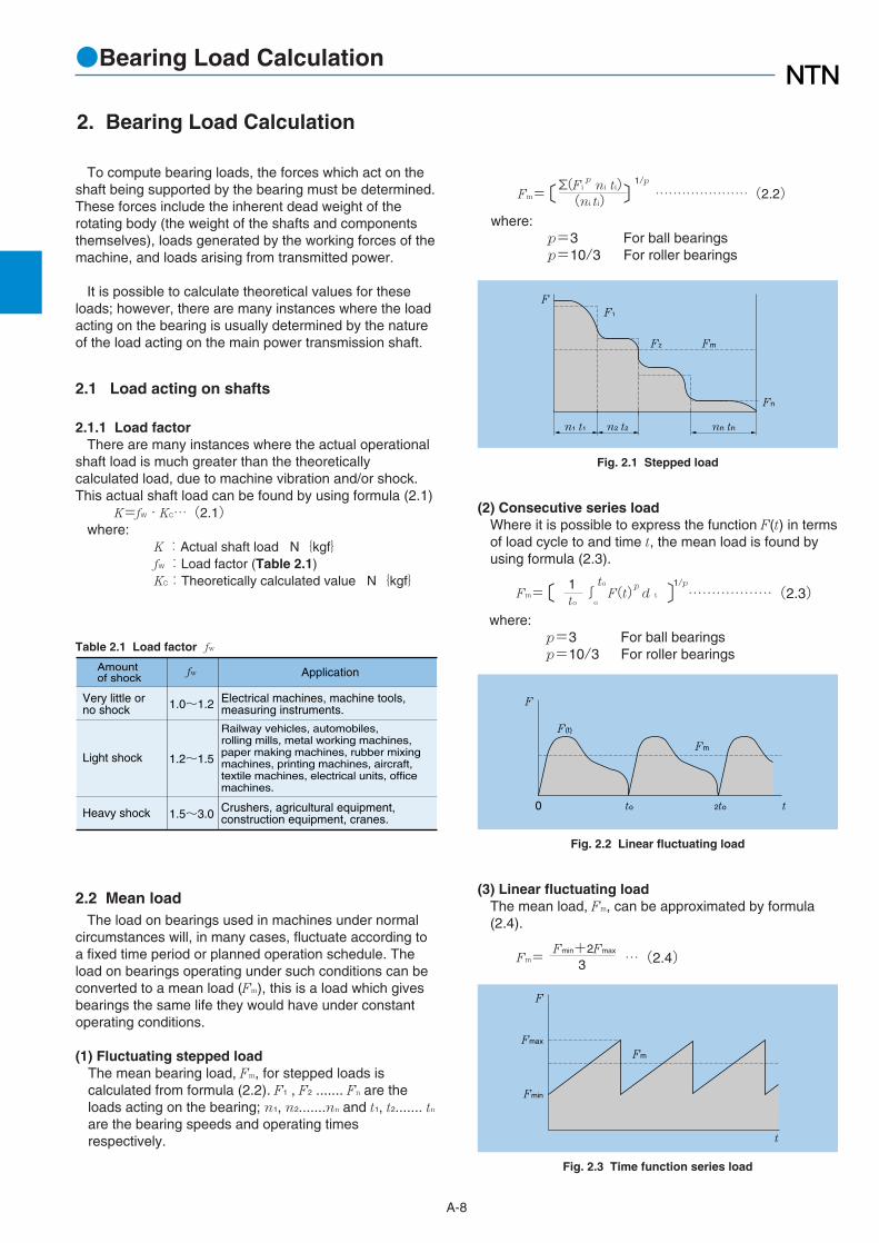
2. Bearing Load Calculation
2.2 Mean loadThe load on bearings used in machines under normal
circumstances will, in many cases, fluctuate according toa fixed time period or planned operation schedule. Theload on bearings operating under such conditions can beconverted to a mean load (Fm), this is a load which givesbearings the same life they would have under constantoperating conditions.
(1) Fluctuating stepped load The mean bearing load, Fm, for stepped loads iscalculated from formula (2.2). F1 , F2 ....... Fn are theloads acting on the bearing; n1, n2.......nn and t1, t2....... tn
are the bearing speeds and operating timesrespectively.
(2) Consecutive series loadWhere it is possible to express the function F(t) in termsof load cycle to and time t, the mean load is found byusing formula (2.3).
Fm=〔 1∫
to
F(t)p
d t 〕1/p………………(2.3)
to o
where:p=3 For ball bearingsp=10/3 For roller bearings
F
F1
FmF2
Fn
nn tnn1 t1 n2 t2
Fig. 2.1 Stepped load
F
Fm
F(t)
2to0 to t
Fig. 2.3 Time function series load
F
Fmax
Fmin
Fm
t
Fig. 2.2 Linear fluctuating load
Fm=〔Σ(Fip
ni ti)〕1/p
…………………(2.2)(ni ti)where:
p=3 For ball bearingsp=10/3 For roller bearings
(3) Linear fluctuating loadThe mean load, Fm, can be approximated by formula(2.4).
Fm=Fmin+2Fmax
…(2.4)3
To compute bearing loads, the forces which act on theshaft being supported by the bearing must be determined.These forces include the inherent dead weight of therotating body (the weight of the shafts and componentsthemselves), loads generated by the working forces of themachine, and loads arising from transmitted power.
It is possible to calculate theoretical values for theseloads; however, there are many instances where the loadacting on the bearing is usually determined by the natureof the load acting on the main power transmission shaft.
2.1 Load acting on shafts
2.1.1 Load factorThere are many instances where the actual operational
shaft load is much greater than the theoreticallycalculated load, due to machine vibration and/or shock.This actual shaft load can be found by using formula (2.1)
K=fw・Kc…(2.1)where:
K:Actual shaft load N{kgf}fw :Load factor (Table 2.1)Kc:Theoretically calculated value N{kgf}
Table 2.1 Load factor fw
Amountof shock Application
Heavy shock
Light shock
Very little orno shock
Electrical machines, machine tools,measuring instruments.
Railway vehicles, automobiles,rolling mills, metal working machines,paper making machines, rubber mixingmachines, printing machines, aircraft, textile machines, electrical units, officemachines.
Crushers, agricultural equipment,construction equipment, cranes.
1.0~1.2
1.2~1.5
1.5~3.0
fw

A-9
●Bearing Load Calculation
Fig. 2.4 Sinusoidal variable load
Fmax
Fm
t
F
F
Fmax
Fm
t
(a)
(b)
(4) Sinusoidal fluctuating loadThe mean load, Fm, can be approximated by formulas(2.5) and (2.6).
case (a) Fm=0.75Fmax ………(2.5)case (b) Fm=0.65Fmax ………(2.6)
(2) Dynamic equivalent axial loadAs a rule, standard thrust bearings with a contact angleof 90˚ cannot carry radial loads. However, self-aligningthrust roller bearings can accept some radial load. Thedynamic equivalent axial load for these bearings isgiven in formula (2.8).
Pa=Fa+1.2Fr………………(2.8)where,
Pa:Dynamic equivalent axial load, NFa:Actual axial load, NFr:Actual radial load, N
Provided that Fr / Fa≦ 0.55 only.
2.3.2 Static equivalent loadThe static equivalent load is a hypothetical load which
would cause the same total permanent deformation at themost heavily stressed contact point between the rollingelements and the raceway as under actual loadconditions; that is when both static radial loads and staticaxial loads are simultaneously applied to the bearing.
For radial bearings this hypothetical load refers to pureradial loads, and for thrust bearings it refers to purecentric axial loads. These loads are designated staticequivalent radial loads and static equivalent axial loadsrespectively.
(1) Static equivalent radial loadFor radial bearings the static equivalent radial load canbe found by using formula (2.9) or (2.10). The greater ofthe two resultant values is always taken for Por.
Por=Xo Fr+Yo Fa…(2.9)Por=Fr…………… (2.10)
where,Por:Static equivalent radial load, NFr:Actual radial load, NFa:Actual axial load, NXo:Static radial load factorYo:Static axial load factor
The values for Xo and Yo are given in the respectivebearing tables.
(2) Static equivalent axial loadFor spherical thrust roller bearings the static equivalentaxial load is expressed by formula (2.11).
Poa=Fa+2.7Fr…(2.11)where,
Poa:Static equivalent axial load, NFa:Actual axial load, NFr:Actual radial load, N
Provided that Fr / Fa≦ 0.55 only.
2.3 Equivalent load
2.3.1 Dynamic equivalent loadWhen both dynamic radial loads and dynamic axial
loads act on a bearing at the same time, the hypotheticalload acting on the center of the bearing giving thebearings the same life as if they had only a radial load oronly an axial load, is called the dynamic equivalent load.
For radial bearings, this load is expressed as pureradial load and is called the dynamic equivalent radialload. For thrust bearings, it is expressed as pure axialload and is called the dynamic equivalent axial load.
(1) Dynamic equivalent radial loadThe dynamic equivalent radial load is expressed byformula (2.7).
Pr=XFr+YFa………………(2.7)where,
Pr:Dynamic equivalent radial load, NFr:Actual radial load, NFa:Actual axial load, NX:Radial load factorY:Axial load factor
The values for X and Y are listed in the bearing tables.

A-10A-30

A-11
●Bearing Tolerances
3.1 Dimensional accuracy and running accuracyBearing “tolerances” or dimensional accuracy and
running accuracy, are regulated by ISO and JIS B 1514standards (rolling bearing tolerances). For dimensionalaccuracy, these standards prescribe the tolerancesnecessary when installing bearings on shafts or inhousings. Running accuracy is defined as the allowablelimits for bearing runout during operation.
Dimensional accuracyDimensional accuracy constitutes the acceptable values
for bore diameter, outer diameter, assembled bearingwidth, and bore diameter uniformity as seen in chamferdimensions, allowable inner ring tapered bore deviationand shape error. Also included are, average bore diametervariation average, outer diameter variation, average outerdiameter unevenness, as well as raceway width andheight variation (for thrust bearings).
Running accuracyRunning accuracy constitutes the acceptable values for
inner and outer ring radial runout and axial runout, innerring side runout, and outer ring outer diameter runout.
Allowable rolling bearing tolerances have beenestablished according to precision classes. JIS Class 0corresponds to normal precision class bearings, andprecision becomes progressively higher as the classnumber becomes smaller; i.e., Class 6 is less precise thanClass 5, which is less precise than Class 4, and so on.
Table 3.1 indicates which standards and precisionclasses are applicable to the major bearing types. Table3.2 shows a relative comparison between JIS B 1514precision class standards and other standards. For greaterdetail on allowable error limitations and values, refer toTables 3.3 - 3.8. Allowable values for chamfer dimensionsare shown in Table 3.9, and allowable error limitations andvalues for radial bearing inner ring tapered bores areshown in Table 3.10.
Table 3.1 Bearing types and applicable tolerance
Table 3.2 Comparison of tolerance classifications of national standards
Bearing type
Deep groove ball bearing
Spherical roller thrust bearings
Thrust tapered roller bearings
Thrust ball bearings
Spherical roller bearings
Tapered roller bearings
Cylindrical roller bearigns
Angular contact ball bearings
Applicable standard Applicable tolerance Tolerance table
metric
Inch
metric
Inch
ISO492
ISO492
ABMA Std.19
ISO199
NTN standard
class 0
class 0
class 0
class 0
class 0,6X
class 4
class 0
class 0
class 0
class 2
class 6
class 6
class 6
class 6
class 2
class 6 class 5
class 3
class 5
class 5
class 5
class 5 class 4
class 4
class 4
class 5
class 0
class 4
class 00
class 2
class 2
class 2
-
- - -
- -
- -
-
-
-
-
- - - -
Table 3.3
Table 3.4
Table 3.5
Table 3.6
Table 3.7
Table 3.8
ANSI/ABMA Std. 23 - - Table 3.8
StandardJapanese industrial standard (JIS)
Tolerance Class Bearing Types
class 0,6X class 6 class 2
International Organizationfor Standardization (ISO)
Deutsches Institutfur Normung(ISO)
American NationalStandards Institute (ANSI)
class 5 class 4JIS B 1514
ISO 492
ISO 199
ISO 578
DIN 620
ANSI/ABMA Std.20
ANSI/ABMA Std.19
Normalclass
Class 6XClass 6
Class 6
Class 2
Normalclass
Class 4
P0
ABEC-1RBEC-1
Class 4
Class 5 Class 4 Class 2
Class 5 Class 4
Class 3 Class 0 Class 00
Class 3 Class 0 Class 00
ABEC-3RBEC-3
ABEC-5RBEC-5
ABEC-7 ABEC-9
P6 P5 P4 P2
-
-
All type
Radial bearings
Thrust ball bearings
Tapered roller bearings (Inch series)
All type
Radial bearings (Except tapered roller bearings)
Tapered roller bearings (Inch series)
Anti-Friction Bearing Manufacturers (ABMA)
1
1 "ABEC" is applied for ball bearings and "RBEC" for roller bearings.Notes: 1. JIS B 1514, ISO 492 and 199, and DIN 620 have the same specification level. 2. The tolerance and allowance of JIS B 1514 are a little different from those of ABMA standards.
3. Bearing Tolerances

A-12
●Bearing Tolerances
Table 3.3 Tolerance for radial bearings (Except tapered roller bearings)Table 3.3 (1) Inner rings
Table 3.3 (2) Outer rings
Nominal bore diameter
d
mm
over incl.
80120150
180250315
400500630
8001,0001,250 1,600
120150180
250315400
500630800
1,0001,2501,600 2,000
Single plane mean bore diameter deviation
∆dmp
000
000
000
000 0
000
000
00ー
ーーーー
000
000
ーーー
ーーー ー
-10-13-13
-15-18-23
ーーー
ーーーー
000
0ーー
ーーー
ーーー ー
-8-10-10
-12ーー
ーーー
ーーーー
000
0ーー
ーーー
ーーーー
-5-7-7
-8ーー
ーーー
ーーーー
-20-25-25
-30-35-40
-45-50-75
-100-125-160-200
-15-18-18
-22-25-30
-35-40ー
ーーーー
Single radial plane bore diameter variation
Vdp
253131
384450
566394
125155200250
192323
283138
4450ー
ーーーー
101313
151823
ーーー
ーーーー
81010
12ーー
ーーー
ーーーー
577
8ーー
ーーー
ーーーー
253131
384450
566394
125155200250
192323
283138
4450ー
ーーーー
81010
121418
ーーー
ーーーー
688
9ーー
ーーー
ーーーー
577
8ーー
ーーー
ーーーー
151919
232630
343855
7594
120150
111414
171923
2630ー
ーーーー
81010
121418
ーーー
ーーーー
688
9ーー
ーーー
ーーーー
577
8ーー
ーーー
ーーーー
1 The dimensional difference ∆ds of bore diameter to applied for class 4 and 2 is the same as the tolerance of dimensional difference ∆dmp of average bore diameter. However, the dimensional difference is applied to diameter series 0, 1, 2, 3 and 4 against Class 4, and to all the diameter series against Class 2.
1 1
high low high low high low high low high low
class 0 class 6 class 5 class 4 class 2
diameter series 9 class
0class
6class
5class
4class
2
max
max diameter series 0,1 class
0class
6class
5class
4class
2
max
max diameter series 2,3,4class
0class
6class
5class
4class
2
max
Nominal outside diameter
D
mm
over incl.
80 120 150
180 250 315
400 500 630
800 1,000 1,250
1,600 2,000
120150180
250315400
500630800
1,0001,2501,600
2,0002,500
Single plane mean outside diameter deviation
∆Dmp
000
000
000
000
0 0
000
000
000
0ーー
ーー
000
000
000
ーーー
ーー
-10-11-13
-15-18-20
-23-28-35
ーーー
ーー
000
000
ーーー
ーーー
ーー
-8-9
-10
-11-13-15
ーーー
ーーー
ーー
000
000
ーーー
ーーー
ーー
-5 -5 -7
-8 -8-10
ー ー ー
ー ー ー
ー ー
-15-18-25
-30-35-40
-45-50-75
-100-125-160
-200-250
-13-15-18
-20-25-28
-33-38-45
-60ーー
ーー
Single radial plane outside diameter variation
VDp
open type
192331
384450
566394
125155200
250310
161923
253135
414856
75ーー
ーー
101113
151820
232835
ーーー
ーー
89
10
111315
ーーー
ーーー
ーー
557
88
10
ーーー
ーーー
ーー
192331
384450
566394
125155200
250310
161923
253135
414856
75ーー
ーー
88
10
111415
172126
ーーー
ーー
678
81011
ーーー
ーーー
ーー
111419
232630
343855
7594
120
150190
101114
151921
252934
45ーー
ーー
88
10
111415
172126
ーーー
ーー
678
81011
ーーー
ーーー
ーー
4 The dimensional difference ∆Ds of outer diameter to be applied for classes 4 and 2 is the same as the tolerance of dimensional difference ∆Dmp of average outer diameter. However, the dimensional difference is applied to diameter series 0, 1, 2, 3 and 4 against Class 4, and also to all the diameter series against Class 2.
557
88
10
ーーー
ーーー
ーー
557
88
10
ーーー
ーーー
ーー
4 4
high low high low high low high low high low
class 0 class 6 class 5 class 4 class 2
diameter series 9class
0class
6class
5class
4class
2
max
max diameter series 0,1class
0class
6class
5class
4class
2
max
max diameter series 2,3,4class
0class
6class
5class
4class
2
max

A-13
●Bearing Tolerances
Mean single planebore diameter variation
Vdmp
151919
232630
343855
7594
120150
111414
171923
2630ー
ーーーー
577
89
12
ーーー
ーーーー
455
6ーー
ーーー
ーーーー
2.53.53.5
4ーー
ーーー
ーーーー
253030
405060
657080
90100120140
131818
202530
3540ー
ーーーー
688
101315
ーーー
ーーーー
566
8ーー
ーーー
ーーーー
2.52.55
5ーー
ーーー
ーーーー
91010
111315
ーーー
ーーーー
566
7ーー
ーーー
ーーーー
2.52.54
5ーー
ーーー
ーーーー
Inner ringradial runout
Kia
Unit μm
Face runoutwith bore
Sd
Inner ringaxial runout(with side)
Sia
91010
131520
ーーー
ーーーー
577
8ーー
ーーー
ーーーー
455
6ーー
ーーー
ーーーー
Inner ring width deviation
∆Bs
000
000
000
0000
-200-250-250
-300-350-400
-450-500-750
-1,000-1,250-1,600-2,000
000
000
ーーー
ーーーー
-200-250-250
-300-350-400
ーーー
ーーーー
000
0ーー
ーーー
ーーーー
-200-250-300
-350ーー
ーーー
ーーーー
-380-500-500
-500-500-630
ーーー
ーーーー
000
000
ーーー
ーーーー
000
000
ーーー
ーーーー
-380-380-380
-500-500-630
ーーー
ーーーー
Inner ring widthvariation
VBs
253030
303540
506070
80100120140
253030
303540
4550ー
ーーーー
788
101315
ーーー
ーーーー
2.52.54
5ーー
ーーー
ーーーー
2.52.55
5ーー
ーーー
ーーーー
2 To be applied to deep groove ball bearing and angular contact ball bearings.3 To be applied to individual raceway rings manufactured for combined bearing use.
23
class 0
class 6
class 5
class 4
class 2
max
class 0
class 6
class 5
class 5
class 4
class 2
class 4
class 2
max max
class 5
class 4
class 2
max high low high lowhigh low
normal
class 0,6 class 5,4
high low high low
class 0,6 class 5,4class 2
modifiedclass
0class
6class
5class
4class
2
max
111419
232630
343855
7594
120
150190
101114
151921
252934
45ーー
ーー
567
89
10
121418
ーーー
ーー
455
678
ーーー
ーーー
ーー
2.52.53.5
445
ーーー
ーーー
ーー
Mean single planeoutside diameter
variationVDmp
Unit μm
Outer ring radial runout
Kea
455
778
ーーー
ーーー
ーー
Outside surfaceinclination
SD
888
101113
151820
ーーー
ーー
2.52.52.5
457
ーーー
ーーー
ーー
5 To be applied to deep groove ball bearings and angular contact ball bearings.
354045
506070
80100120
140160190
220250
182023
253035
405060
75ーー
ーー
101113
151820
232530
ーーー
ーー
678
101113
ーーー
ーーー
ーー
555
778
ーーー
ーーー
ーー
91010
111313
151820
ーーー
ーー
555
78
10
ーーー
ーーー
ーー
2.52.52.5
457
ーーー
ーーー
ーー
Outside ringaxial runout
Sea
111314
151820
232530
ーーー
ーー
678
101013
ーーー
ーーー
ーー
555
778
ーーー
ーーー
ーー
5
class 0
class 6
class 5
class 4
class 2
max
class 0
class 6
class 5
class 4
class 2
max
class 5
class 4
class 2
max
class 5
class 4
class 2
max
class 5
class 4
class 2
max
Outer ring widthvariation
VCs

●Bearing Tolerances
A-14
Table 3.4 Tolerance of tapered roller bearings (Metric system)
Table 3.4 (1) Inner rings
Table 3.4 (2) Outer rings
80120180
250315400
500630800
1,0001,250
120180250
315400500
630800
1,000
1,2501,600
000
000
000
00
000
ーーー
ーーー
ーー
000
ーーー
ーーー
ーー
-10-13-15
ーーー
ーーー
ーー
-20-25-30
-35-40-45
-50-75
-100
-125-160
-15-18-22
ーーー
ーーー
ーー
1 The dimensional difference ∆ds of bore diameter to be applied for class 4 is the same as the tolerance of dimensional difference ∆dmp of average bore diameter.
202530
354045
5075
100
125160
151822
ーーー
ーーー
ーー
111417
ーーー
ーーー
ーー
81011
ーーー
ーーー
ーー
151923
263034
385675
94120
1114
16
ーーー
ーーー
ーー
89
11
ーーー
ーーー
ーー
578
ーーー
ーーー
ーー
303550
607080
90105120
140160
131820
ーーー
ーーー
ーー
81113
ーーー
ーーー
ーー
568
ーーー
ーーー
ーー
91011
ーーー
ーーー
ーー
567
ーーー
ーーー
ーー
over incl.
Single plane mean borediameter deviation
∆dmp
Single radial planebore diameter variation
Vdp
Mean single planebore diameter variation
Vdmp
Inner ring radial runout
Kia
Facerunout
with boreSd
1class 0,6X class 5,6
high low high low high low class 4
class0,6X
class6
class5
class4
max
class0,6X
class6
class5
class4
max
class0,6X
class6
class5
class4
class5
class4
max max
Nominal bore diameter
d
mm
80120150
180250315
400500630
8001,0001,2501,600
120150180
250315400
500630800
1,0001,2501,6002,000
000
000
000
0000
000
000
ーーー
ーーーー
000
000
ーーー
ーーーー
-10-11-13
-15-18-20
ーーー
ーーーー
-18-20-25
-30-35-40
-45-50-75
-100-125-160-200
-13-15-18
-20-25-28
ーーー
ーーーー
2 The dimensional difference ∆Ds of outside diameter to be applied for class 4 is the same as the tolerance of dimensional difference ∆Dmp of average outside diameter.3 ∆Ds as the same as ∆Dmp in the case of class 4.
182025
303540
455075
100125160200
131518
202528
ーーー
ーーーー
101114
151922
ーーー
ーーーー
88
10
111415
ーーー
ーーーー
141519
232630
343856
7584
120150
101114
151921
ーーー
ーーーー
789
101314
ーーー
ーーーー
567
89
10
ーーー
ーーーー
354045
506070
80100120
140165190230
182023
253035
ーーー
ーーーー
101113
151820
ーーー
ーーーー
678
101113
ーーー
ーーーー
91010
111313
ーーー
ーーーー
555
78
10
ーーー
ーーーー
Nominal outside diameter
Single plane mean outsidediameter deviation
∆Dmp
Single radial planeoutside diameter
variationVDp
Mean single planeoutside diameter
variationVDmp
Outer ring radial runout
Kea
Outsidesurface
inclinationSD
2
3class 0,6X class 5,6 class 4
class0,6X
class6
class5
class4
max
class0,6X
class6
class5
class4
max
class0,6X
class6
class5
class4
max
class5
class4
maxover incl.
D
mmhigh low high low high low
Single Double Row(outside direction)
Double Row(inside direction)
Four Row
T
φD φd φdφD
C1
B
φD φd
C
φD φd
C2
B2B1

●Bearing Tolerances
A-15
Table 3.4 (3) Effective width of outer and inner rings with roller
000
000
000
00
00
0
00ー
ーーー
ーー
000
ーーー
ーーー
ーー
-400-500-600
ー ー ー
ー ー ー
ー ー
-200-250-300
-350-400-450
-500-750
-1,000
-1,200-1,500
-50-50-50
-50-50ー
ーーー
ーー
+200+350+350
+350+400ー
ー ー ー
ー ー
-200-250-250
-250-400 ー
ー ー ー
ー ー
+400+500+600
+700+800+900
+1,000+1,500+1,500
+1,500+1,500
578
ーーー
ーーー
ーー
+100+150+150
+200+200ー
ー ー ー
ー ー
000
00ー
ーーー
ーー
+200+350+350
ー ー ー
ー ー ー
ー ー
-200-250-250
ー ー ー
ー ー ー
ー ー
-400-500-600
-700-800-900
-1,000-1,500-1,500
-1,500-1,500
+500+600+750
+900+1,000+1,200
+1,200+1,500+1,500
+1,500+1,500
-500-600-750
-900-1,000-1,200
-1,200-1,500-1,500
-1,500-1,500
Unit μm
Inner ringaxial runout(with side)
Sia
Inner ring width deviation
∆Bs
∆Ts
Overall width deviationof assembled double rowstapered roller bearing orheight deviation
Overall width deviationof assembled four rowstapered roller bearingor height deviation
max high low high low high low high low high low high low high lowclass 4 class 0,6 class 6X class 4,5 class 0,6 class 6X class 4,5 class 0,6,5 class 0,6,5
high low
Overall width deviation of assembled singlerow tapered roller bearing, or height deviation
∆B2s, ∆C2s ∆B1s, ∆C1s
000
000
00ー
ーーーー
-100-100-100
-100-100-100
-100-100ー
ーーーー
678
101013
ーーー
ーーーー
Identical to ∆Bs
inner ring ofsame bearing
4 To be applied for nominal bore diameters of 406.400mm (16 inch) or lass.
Outer ring axialrunout
Sea
Outer ring width deviation
∆Cs
Unit μm
4class 0,6,5,4 class 6Xclass 4
max sup. inf. sup. inf.
+100+150+150
+150+200
80120180
250315
120180250
315400
-100-150-150
-150-200
+50+50+50
+100+100
000
00
+100+200+200
+200+200
-100-100-100
-100-200
+50+100+100
+100+100
000
00
over incl.
Effective width deviationof roller and inner ring assemblyof tapered roller bearing ∆T1s
Unit μm
Tapered roller bearing outerring effective width deviation
∆T2s
high low high lowclass 0 class 6X class 0 class 6X
high low high low
Nominal bore diameter
d mm
T1 T2
Master conesub-unit
Master cupsub-unit
φd φd
●Bearing Tolerances
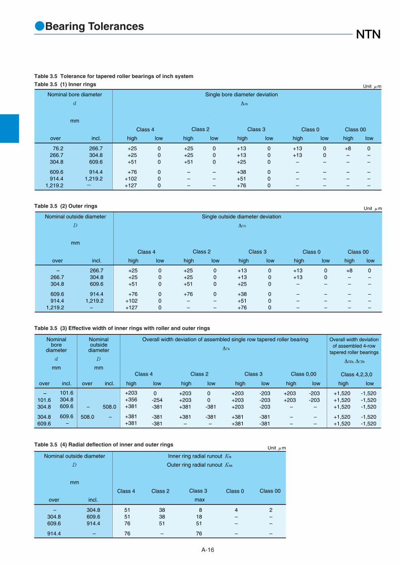
A-16
Table 3.5 Tolerance for tapered roller bearings of inch system
Table 3.5 (1) Inner rings
Table 3.5 (2) Outer rings
Table 3.5 (3) Effective width of inner rings with roller and outer rings
Table 3.5 (4) Radial deflection of inner and outer rings
+25+25+51
+76+102+127
000
000
+25+25+51
–––
000
–––
+13+13+25
+38+51+76
000
000
+13+13
–
–––
00–
–––
+8––
–––
0––
–––
76.2266.7304.8
609.6914.4
1,219.2
266.7304.8609.6
914.41,219.2-
Single bore diameter deviation
∆ds
Class 4
Class 2
Class 3
Class 0
Class 00
Unit μm
Nominal bore diameter
d
mm
over incl. high low high low high low high low high low
– 266.7304.8
609.6914.4
1,219.2
266.7304.8609.6
914.41,219.2
–
+25+25+51
+76+102+127
000
000
+25+25+51
+76– –
000
0––
+13+13+25
+38+51+76
000
000
+13+13
–
– – –
00–
– – –
+8––
–––
0––
–––
Nominal outside diameter
D
mm
Single outside diameter deviation
∆Ds
Unit μm
over incl.
Class 4
Class 2
Class 3
Class 0
Class 00
high low high low high low high low high low
– 101.6304.8
304.8609.6
101.6304.8609.6
609.6–
+203+356+381
+381+381
0-254-381
-381-381
+203+203+381
+381–
00
-381
-381–
+203+203+203
+381+381
-203-203-203
-381-381
+203+203
–
– –
-203-203
–
– –
+1,520+1,520+1,520
+1,520+1,520
-1,520-1,520-1,520
-1,520-1,520
–
508.0
508.0
–
Nominalbore
diameter
d
mm
Overall width deviation of assembled single row tapered roller bearing
∆Ts
Class 4,2,3,0
Nominaloutside
diameter
D
mm
Overall width deviationof assembled 4-row
tapered roller bearings
∆B2s, ∆C2s
over incl. over incl. high low
Class 4
high low
Class 2
high low
Class 3
high low high low
Class 0,00
515176
76
383851
–
81851
76
4––
–
2––
–
– 304.8609.6
914.4
304.8609.6914.4
–
Class 2
Class 0
Unit μm
Nominal outside diameter
D
mm
Inner ring radial runout Kia
Outer ring radial runout Kea
Class 4
Class 3
max
Class 00
over incl.

A-17
●Bearing Tolerances
+102+152
–
– –
0-152
–
– –
+102+102+178
– –
00
-178
– –
+102+102+102
– –
-102-102-102
– –
+102+203
–
– –
0-102
–
– –
+102+102+203
– –
00
-203
– –
+102+102+102
– –
-102-102-102
– –
1 To be applied for nominal bore diameters of 406.400 mm (16 inch) or less.
1 11 1
Effective width deviation of roller and innerring assembly of tapered roller bearing
∆T1s
Unit μm
Tapered roller bearing outer ring effective width deviation
∆T2s
Class 4
high low
Class 2
high low
Class 3
high low
Class 4
high low
Class 2
high low
Class 3
high low
T1 T2
Master conesub-unit
Master cupsub-unit
φd φd
Single Double Row(outside direction)
Double Row(inside direction)
Four Row
T
φD φd φdφD
C1
B
φD φd
C
φD φd
C2
B2B1

●Bearing Tolerances
A-18
000
000
0000
-22-25-30
-35-40-45
-50-75
-100-125
000
000
000–
-13-15-20
-25-28-33
-38-45-60
–
80120180
250315400
500630800
1,000
120180250
315400500
630800
1,0001,250
171923
263034
38557595
101115
192125
293445–
According to the toleranceof S1 against "d" or "d2"of the same bearings
Nominal outsidediameter
D
mm
over incl.
Single plane mean outside diameter deviation
∆Dmp
Single radial planeoutside diameter
variation
VDp
Thrust bearing housing washer racewaythickness variation
Se
Unit μm
Class
0,6,5
high low
Class
4
high low
Class
0,6,5
Class
4
max
Class
0
Class
6
Class
5
Class
4
max
000
000
000
-20-25-30
-35-40-45
-50-75
-100
000
000
00–
-15-18-22
-25-30-35
-40-50–
80120180
250315400
500630800
120180250
315400500
630800
1,000
151923
263034
385575
111417
192326
30– –
151520
253030
354045
89
10
131518
212530
455
779
111315
344
556
78–
Nominal bore diameter
d
mm
over incl.
Single radial planebore diameter variation
Vdp
Thrust bearing shaft washer raceway(or center washer raceway) thickness variation
Si
Unit μm
Class
0,6,5
high low
Class
4
high low
Class
0,6,5
Class
4
max
Class
0
Class
6
Class
5
Class
4
max
Single plane mean bore diameter deviation
∆dmp
Table 3.6 (2) Housing washer
Table 3.6 (3) Height of bearings center washer
Table 3.6 Tolerance of thrust ball bearings
Table 3.6 (1) Shaft washer
000
000
000
-150-175-200
-225-300-350
-400-500-600
80120180
250315400
500630800
120180250
315400500
630800
1,000
1 This standard is applied to flat back face bearing of class 0.
Nominal borediameter
d
mm
over incl. high low
Unit μm
Single direction type �
� ∆Ts
1
φD
φd
T

●Bearing Tolerances
A-19
Table 3.7 Tolerance of spherical thrust roller bearing
Table 3.7 (1) Shaft washer
Table 3.7 (2) Housing washer
Table 3.8 Tolerance of thrust tapered roller bearings
Table 3.8 (1) Shaft washer (metric series)
Table 3.8 (3) Shaft washer (inch series)
Table 3.8 (2) Housing washer (metric series)
120 180 0 -25 19 30 +250 -250180 250 0 -30 23 30 +300 -300
250 315 0 -35 26 35 +350 -350315 400 0 -40 30 40 +400 -400400
500630
500
630800
0
00
-45
-50-75
34
3855
45
5060
+450
+500+750
-450
-500-750
80 120 0 -20 15 25 +200 -200
Unit μm
Nominalbore diameter
d
mm over incl. high low high lowmax max
Single radialplane borediametervariation
Vdp
Facerunout
with bore
Sd
Height deviation ofsingle directionthrust bearing
∆Ts
Single plane meanbore diameter deviation
∆dmp
80120180
250315400
500630800
120180250
315400500
630800
1,000
000
000
000
-20-25-30
-35-40-45
-50-75
-100
000
000
000
-150-175-200
-225-300-350
-400-500-600
Single plane meanbore diameter
deviation
∆dmp
high low
Bearing hightdeviation
∆Ts
high low
Unit μm
Nominal outside diameter
d
mm
over incl.
180250315
400500630
8001,000
250315400
500630800
1,0001,250
000
000
00
-30-35-40
-45-60-75
-100-125
Unit μm
Nominal outside diameter
D
mm
Single plane meanoutside diameter
deviation
∆Dmp
over incl. high low
–304.800
609.600914.400
Nominalbore diameter
d
Single plane meanbore diameter
deviation
∆dmp
Bearing hightdeviation
∆Ts
high low high lowmm
Unit μm
over
304.800609.600
914.4001,219.200
+25 +51
+76+102
00
00
+381+381
+381+381
-381-381
-381-381
mm
incl.
Table 3.8 (4) Housing washer (inch series)
– 304.800609.600
914.4001,219.200
Nominal outside diameter
D
Single plane meanoutside diameter
deviation
∆Dmp
mm
Unit μm
over
304.800609.600914.400
1,219.200–
+25 +51 +76
+102+127
000
00
mm
incl.
high low
φd
φD
T
φD
T
φd
φD
T
φd
120180250
315400500
630800
1,0001,250
180250315
400500630
8001,0001,2501,600
000
000
0000
-25-30-35
-40-45-50
-75-100-125-160
Unit μm
Nominal outside diameter
d
mm
Single plane meanoutside diameter
deviation
∆Dmp
over incl. high low

●Bearing Tolerances
A-20
0.6
1
1.1
1.5
2.1
3
2.5
4
5
6
7.5
9.5
12
15
19
2
–
40
–
50
–
120
–
120
–
80
220
–
280
–
100
280
–
280
–
–
–
–
–
–
–
–
40
–
50
–
120
–
120
–
80
220
–
280
–
100
280
–
280
–
–
–
–
–
–
–
–
–
1
1.3
1.5
1.9
2
2.5
2.3
3
3
3.5
3.8
4
4.5
3.8
4.5
5
5
5.5
6.5
8
10
12.5
15
18
21
25
2
2
3
3
3.5
4
4
5
4.5
5
6
6.5
7
6
6
7
8
8
9
10
13
17
19
24
30
38
1 These are the allowable minimum dimensions of the chamfer dimension "r" or "r1" and are described in the dimensional table.
Unit mm
rs min1
or
r1s min
Nominalbore diameter
d over incl.
rs max or r1s max
Radialdirection
Axialdirection
Table 3.9 Allowable critical-value of bearing chamfer
Table 3.9 (1) Radial bearing (except tapered roller bearing) Table 3.9 (2) Tapered roller bearings of metric system
0.3
0.6
1
5
3
–
40
–
40
–
50
–
120
250
–
120
250
–
120
250
–
120
250
400
–
120
250
400
–
180
–
180
40
–
40
–
50
–
120
250
–
120
250
–
120
250
–
120
250
400
–
120
250
400
–
180
–
180
–
0.7
0.9
1.1
1.3
1.6
1.9
2.3
2.8
3.5
2.8
3.5
4
3.5
4
4.5
4
4.5
5
5.5
5
5.5
6
6.5
6.5
7.5
7.5
9
1.4
1.6
1.7
2
2.5
3
3
3.5
4
4
4.5
5
5
5.5
6
5.5
6.5
7
7.5
7
7.5
8
8.5
8
9
10
11
2 These are the allowable minimum dimensions of the chamfer dimension "r" or "r1" and are described in the dimensional table.3 Inner rings shall be in accordance with the division of "d" and outer rings with that of "D".
Note: This standard will be applied to the bearings whose dimensional series (refer to the dimensional table) are specified in the standard of ISO 355 or JIS B 1512. Please consult NTN Engineering on non-standard bearings.
1.5
2
2.5
4
6
Unit mm
rs min2
or
r1s min
rs max or r1s max
Radialdirection
Axialdirection
Nominal bore3
diameter of bearing"d" or nominal
outside diameter "D"
over incl.
3.2 Limits and tolerances for chamfer andtapered bore Side face of inner
ring or centerwasher, or side faceof outer ring
Bore diameter face of bearing or outer diameter face ofbearing (Axial direction)
rs min or r1s min (Rad
ial d
irect
ion)
rs max or r1s max
rsm
in o
r r
1sm
in
rsm
ax o
r r
1sm
ax
rs min or r1s min

●Bearing Tolerances
A-21
Table 3.9 (3) Thrust bearingsTable 3.10 (1) Tolerance and allowable values (Class 0) of
tapered bore of radial bearings
Table 3.10 (2) Allowable variations for radial bearing inner ringtapered bores standard taper ratio 1:30 (Class 0)
120180250
315400500
630800
1,000
1,2501,600
80120180
250315400
500630800
1,0001,250
000
546372
+++
000
818997
+++
000
110125140
+++
00
165195
++
000
35404652
+++
000
5763
+++
000
708090
+++
00
105125
++
224046
525763
70––
––
d mm
over incl. high low high low max
Vdp∆dmp
Unit μm
-∆d1mp ∆dmp1 2
120180250
315400500630
80120180
250315400500
000
+20+25+30
0000
+35+40+45+50
000
+35+40+46
0000
+52+57+63+70
224046
52576370
d mm
over incl. low
Vdp
max
∆dmp highlowhigh
Units μm1 2-∆d1mp ∆dmp
1 Applies to all radial flat planes of inner ring tapered bore. 2 Does not apply to diameter series 7 and 8.
Note: Quantifiers
For a standard taper ratio of 1:12 d1=d+ B
For a standard taper ratio of 1:30 d1=d+ B
∆dmp :Dimensional difference of the average bore diameter within the flat surface at the theoretical small end of the tapered bore. ∆d1mp:Dimensional difference of the average bore diameter within the flat surface at the theoretical large end of the tapered bore. Vdp :Unevenness of the bore diameter with the flat surface B :Nominal width of inner ring α :Half of the tapered bore’s nominal taper angle For a standard taper ratio of 1:12 α=2˚23′9.4″ For a standard taper ratio of 1:30 α=0˚57′7.4″
112130
0.6
1
1.1
1.5
2
2.1
4
3
5
6
7.5
9.5
19
12
15
1.5
2.2
2.7
3.5
4
4.5
5.5
6.5
21
15
25
10
8
12.5
18
4 These are the allowable minimum dimensions of the chamfer dimension "r" or "r1" and are described in the dimensional table.
rs max or r1s max
Radial and axial direcitionrs min or r1 min
4
Unit mm
2α 2α ∆dmpφd+
BB
φd1+φd1+∆dmp ∆d1mpφd1φd
Theoretical tapered hole Tapered hole having dimensionaldifference of the average borediameter within the flat surface

A-22
●Bearing Fits
¡Raceway cracking, early peeling and displacement ofraceway
¡Raceway and shaft or housing abrasion caused bycreeping and fretting corrosion
¡Seizing caused by loss of internal clearances¡Increased noise and lowered rotational accuracy due
to raceway groove deformation
4.3 Fit selectionSelection of a proper fit is dependent upon thorough
analysis of bearing operating conditions, includingconsideration of:¡Shaft and housing material, wall thickness, finished
surface accuracy, etc. ¡Machinery operating conditions (nature and
magnitude of load, rotational speed, temperature,etc.)
4.3.1 "Tight fit," "transition fit," or "loose fit"(1) For raceways under rotating loads, a tight fit is
necessary. (refer to Table 4.1) "Raceways underrotating loads" refers to raceways receiving loadsrotating relative to their radial direction. For racewaysunder static loads, on the other hand, a loose fit issufficient.(Example) Rotating inner ring load = the direction of
the radial load on the inner ring is rotatingrelatively
(2) For non-separable bearings, such as deep groove ballbearings, it is generally recommended that either theinner ring or outer ring be given a loose fit.
4.1 InterferenceFor rolling bearings, inner and outer rings are fixed on
the shaft or in the housing so that relative movementdoes not occur between fitted surfaces during operationor under load. This relative movement (referred to as"creep") between the fitted surfaces of the bearing andthe shaft or housing can occur in a radial direction, anaxial direction, or in the direction of rotation. To helpprevent this creeping movement, bearing rings and theshaft or housing are installed with one of threeinterference fits, a "tight fit" (also called shrink fit),"transition fit," or "loose fit" (also called clearance fit),and the degree of interference between their fittedsurfaces varies.
The most effective way to fix the fitted surfacesbetween a bearing's raceway and shaft or housing is toapply a "tight fit." The advantage of this tight fit for thinwalled bearings is that it provides uniform load supportover the entire ring circumference without any loss of loadcarrying capacity. However, with a tight fit, ease ofinstallation and disassembly is lost; and when using anon-separable bearing as the floating-side bearing, axialdisplacement is not possible. For this reason, a tight fitcannot be recommended in all cases.
4.2 The necessity of a proper fitIn some cases, improper fit may lead to damage and
shorten bearing life, therefore it is necessary to make acareful analysis in selecting a proper fit. Some of thenegative conditions caused by improper fit are listedbelow.
Table 4.1 Radial load and bearing fit
Illustration Ring load Fit
Rotating innerring load
Static outerring load
Inner ring :Tight fit
Outer ring :Loose fit
Inner ring : Loose fit
Outer ring : Tight fit
Static innerring load
Rotating outerring load
Inner ring:Rotatring
Outer ring:Stationary
Inner ring:Stationary
Outer ring:Rotating
Inner ring:Stationary
Outer ring:Rotating
Inner ring:Rotating
Outer ring:Stationary
Bearing rotationStaticload
Staticload
Unbalancedload
Unbalancedload
4. Bearing Fits

●Bearing Fits
A-23
4.3.2 Recommended FitsBearing fit is governed by the selection tolerances for
bearing shaft diameters and housing bore diameters. Widely used fits for 0 Class tolerance bearings and
various shaft and housing bore diameter tolerances areshown in Fig. 4.1.
Generally-used, standard fits for most types of bearingsand operating conditions are shown in Tables 4.2 - 4.6.
Table 4.2: Fits for radial bearingsTable 4.3: Fits for thrust bearingsTable 4.4: Fits for electric motor bearingsTable 4.5: Fits for inch series tapered roller bearings
(ANSI Class 4)Table 4.6: Fits for inch series tapered roller bearings
(ANSI Class 3 and 0)Table 4.5. shows fits and their numerical values.
For special fits or applications, please consult NTNEngineering.
4.3.3 Interference minimum and maximum valuesThe following points should be considered when it is
necessary to calculate the interference for an application:¡In calculating the minimum required amount of
interference keep in mind that:1) interference is reduced by radial loads2) interference is reduced by differences between
bearing temperature and ambient temperature3) interference is reduced by variation of fitted
surfaces¡Maximum interference should be no more than
1:1000 of the shaft diameter or outer diameter. Required interference calculations are shown below.
(1) Radial loads and required interference Interference between inner rings mounted on solid
shafts is reduced when acted upon by radial loads.Calculation of the minimum required amount ofinterference in such cases is shown in formulae (4.1) and(4.2).
Fr≦ 0.3 Cor
∆ dF = 0.08 (d・Fr / B)1/2 N }………(4.1)= 0.25 (d・Fr / B)1/2 {kgf }Fr> 0.3 Cor
∆ dF = 0.02 (Fr / B) N }………(4.2)= 0.2 (Fr / B) {kgf }Where,
∆ dF : Required effective interference for load μmd : Nominal bore diameter mmB : Inner ring width mm
Fr : Radial load N{kgf}Cor : Basic static rated load N{kgf}
(2) Temperature difference and required interferenceInterference between inner rings and steel shafts is
reduced as a result of temperature increases (differencebetween bearing temperature and ambient temperature,∆T) caused by bearing rotation. Calculation of theminimum required amount of interference in such cases is
G6G7
H7H6
H8
M6 M7N6 N7
P6 P7
p6
n6n5m6m5
k6k5
h6h5
g6g5∆dmp
∆Dmp
Loose fit
Types of fits
Tight fit
Tight fit
Housing
Shafts
Class 0 J6 J7
K6 K7
J6J5
Transition fit
Transition fit
Class 0
Fig. 4.1
shown in formulae (4.3).∆ dT = 0.0015 d ∆T ……………………………………(4.3)
∆ dT : Required effective interference fortemperature difference μm
∆T : Difference between bearing temperatureand ambient temperature ˚C
d : Bearing bore diameter mm
(3) Fitted surface variation and required interferenceInterference between fitted surfaces is reduced by
roughness and other slight variations of these surfaceswhich are flattened in the fitting process. The degree ofreduced interference depends upon the finish treatmentof these surfaces, but in general it is necessary toassume the following interference reductions.
For ground shafts: 1.0~2.5μmFor lathed shafts: 5.0~7.0μm
(4) Maximum interferenceWhen bearing rings are installed with an interference fit,
tension or compression stress may occur along theirraceways. If interference is too great, this may causedamage to the rings and reduce bearing life. For thesereasons, maximum interference should not exceed thepreviously mentioned ratio of 1:1,000 of shaft or outsidediameter.
4.3.4 Other details(1) Tight interference fits are recommended for,
¡Operating conditions with large vibration or shockloads
¡Applications using hollow shafts or housings withthin walls
¡Applications using housings made of light alloys orplastic
(2) Loose interference fits are preferable for,¡Applications requiring high running accuracy¡Applications using small sized bearings or thin
walled bearings
A-24
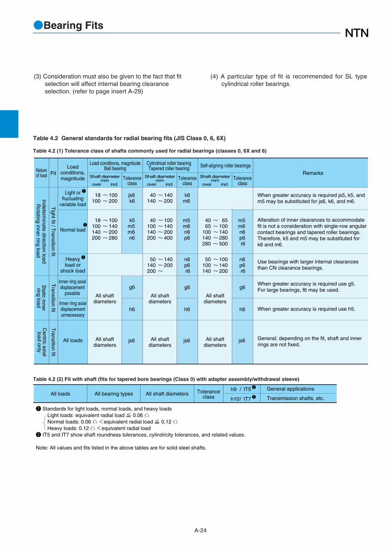
●Bearing Fits
Table 4.2 (1) Tolerance class of shafts commonly used for radial bearings (classes 0, 6X and 6)
Table 4.2 General standards for radial bearing fits (JIS Class 0, 6, 6X)
Rotating inner ring load
Tight fit / T
ransition fit
Indeterminate direction load
Transition fit
Static innerring load
Transition fit
Centric axialload only
Loadconditions,magnitude
Light orfluctuating
variable load
Normal load
Heavyload or
shock load
Inner ring axialdisplacement
possible
Inner ring axialdisplacementunnecessary
All loads
Load conditions, magnitudeBall bearingNature
of load FitShaft diameter
mm over incl
Toleranceclass
Shaft diametermm
over incl Tolerance
classShaft diameter
mm over incl
Toleranceclass
100200
~~
18100
js6k6
65100140280500
~~~~~
4065
100140280
m5m6n6p6r6
Self-aligning roller bearings
140200
~~
40140
k6m6
When greater accuracy is required js5, k5, andm5 may be substituted for js6, k6, and m6.
100140200
~~~
50100140
n6p6r6
140200
~~~
50140200
n6p6r6
100140200400
~~~~
40100140200
m5m6n6p6
100140200280
~~~~
18100140200
k5m5m6n6
Use bearings with larger internal clearancesthan CN clearance bearings.
Alteration of inner clearances to accommodatefit is not a consideration with single-row angularcontact bearings and tapered roller bearings.Therefore, k5 and m5 may be substituted fork6 and m6.
When greater accuracy is required use g5.For large bearings, f6 may be used.
When greater accuracy is required use h5.
General; depending on the fit, shaft and innerrings are not fixed.
All shaftdiameters
All shaftdiameters
All shaftdiameters
All shaftdiameters
All shaftdiameters
All shaftdiameters
g6
h6
g6
h6
g6
h6
Remarks
js6
js6
js6
Cylindrical roller bearingTapered roller bearing
1
1
1
All loads Toleranceclass
All shaft diametersAll bearing types /
/
h9
h10
IT5
IT7
General applications
Transmission shafts, etc.
1 Standards for light loads, normal loads, and heavy loads Light loads: equivalent radial load ≦ 0.06 Cr Normal loads: 0.06 Cr <equivalent radial load ≦ 0.12 Cr Heavy loads: 0.12 Cr <equivalent radial load2 IT5 and IT7 show shaft roundness tolerances, cylindricity tolerances, and related values.
Note: All values and fits listed in the above tables are for solid steel shafts.
2
2
Table 4.2 (2) Fit with shaft (fits for tapered bore bearings (Class 0) with adapter assembly/withdrawal sleeve)
(3) Consideration must also be given to the fact that fitselection will affect internal bearing clearanceselection. (refer to page insert A-29)
(4) A particular type of fit is recommended for SL typecylindrical roller bearings.

A-25
●Bearing Fits
Table 4.2 (3) Housing fits
Rotating outer ring load or
static outer ring load
Solid or splithousing
Tight fit
Transition
or loose fitT
ight totransition fit
Inner ring staticload or outer
ring rotating loadCentered axial
load only - Loose fit
Loose fitLoose fit
Solid housing
Dire
ctio
nin
dete
rmin
ate
load
Toleranceclass
Outer ring axialdisplacement
Natureof load Housing Fit Load conditions, magnitude Remarks
All loads
Light to normal load
Shaft and inner ringsreach high temperature
Requires silent operation
High rotation accuracyrequired with light tonormal loads
Light to normal load
Normal to heavy load
Heavy shock load
Light or variable load
Normal to heavy load
Heavy load (thin wall housing)or heavy shock load
H7
G7
H8
G7
F7
H6
Js6
K6
Js7
K7
M7
M7
N7
P7
Displacement possible
Easy displacement
Displacement possible
Easy displacement
Easy displacement
Displacement possible
Displacement not possible(in principle)
Displacement not possible(in principle)
Displacement possible
Displacement not possible(in principle)
Displacement not possible
Displacement not possible
Displacement not possible
Displacement not possible
Select a tolerance class that willprovide clearance between outerring and housing.
G7 also acceptable for large typebearings as well as outer rings andhousings with large temperature differences.
F7 also acceptable for large type bearings aswell as outer rings and housings with largetemperature differences.
Applies primarily to ball bearings
Applies primarily to roller bearings
When greater accuracy is requiredsubstitute Js6 for Js7 and K6 for K7.
Applies primarily to ball bearings
Applies primarily to roller bearings
2
1
1 Standards for light loads, normal loads, and heavy loads Light loads: equivalent radial load ≦ 0.06 Cr Normal loads: 0.06 Cr <equivalent radial load ≦ 0.12 Cr Heavy loads: 0.12 Cr < equivalent radial load2 Indicates whether or not outer ring axial displacement is possible with non-separable type bearings.
Notes: 1. All values and fits listed in the above tables are for cast iron or steel housings. 2. In cases where only a centered axial load acts on the bearing, select a tolerance class that will provide clearance in the axial direction for the outer ring.

●Bearing Fits
A-26
Table 4.3 (1) Shaft fits
Table 4.3 Standard fits for thrust bearings (JIS Class 0 and 6)
Table 4.4 Fits for electric motor bearings
Bearing type Load conditions Fit Tolerance class
All thrust bearings
Self-aligning rollerthrust bearings
Centered axial load only
Combined load
Inner ring static load
Transition fit
Transition fit All sizes
js6 or h6
Inner ring rotating loador
direction indeterminate load
Transition fit
Tight fit
~ ~ ~
200400
― 200400
k6 or js6m6 or k6n6 or m6
js6
Shaft diametermm
over incl
All sizes
Bearing type Load conditions Fit Toleranceclass
Remarks
All thrustbearings
Self-aligningroller thrust
bearings
Centered axial load only
Combined load
Outer ring static load
Direction Indeterminateload or outer ringrotating load
Loose fit
Transition fit
Select a tolerance class that will provide clearance between outer ring and housing.
H8
H7
K7
M7
Greater accuracy required with thrust ball bearings
Normal operating conditions
For relatively large radial loads
Note: All values and fits listed in the above tables are for cast iron or steel housings.
Table 4.3 (2) Housing fits
Bearing type
Deep grooveball bearings
Cylindricalroller bearings
Shaft fitsShaft diameter mm
over incl. Tolerance class
~ ~
100160
18100
~ ~
160200
40160
k5m5
m5n6
Housing bore diameter
Housing fits Tolerance class
All sizes
All sizes
H6 or J6
H6 or J6

●Bearing Fits
A-27
Table 4.5 Fits for inch series tapered roller bearing (ANSI class 4)
Load conditionsShaft diameter
over incl. high low high low max mind mm
Cone bore tolerance
∆ds
Shaft tolerance Extreme fitsRemark
Normal loads,no shock
Heavy loads orshock loads
Cone axialdisplacementon shaftnecessary
Cone axialdisplacementon shaftunnecessary
304.8609.6914.4
76.2304.8609.6
~~~
304.8609.6914.4
76.2304.8609.6
~~~
304.8609.6914.4
76.2304.8609.6
~~~
304.8609.6914.4
76.2304.8609.6
~~~
+25+51+76
000
+25+51+76
000
+25+51+76
000
+25+51+76
000
3876
114
+++
000
255176
---
64127190
+++
255176
+++
000
~~~
~~~
~~~
13T25T38T
64T127T190T
25T51T76T
50L102L152L
000
25L51L76L
Use average tight cone fit of 0.5μm/mm,(0.0005 inch/inch) of cone bore, use aminimum fit of 25μm, 0.0010 inch tight.
Unit μm
1)
Rotating cone load
Stationary cone load
Applicable when slight impact load is applied as well.
Not applicable when impact load is applied.
Table 4.5 (2) Fit with housing
Load conditions
over incl. high low high low max min
Housing bore diameterD mm
Cup O.D.tolerance
Housing boretolerance
Extreme fitsTypes of fit
127.0304.8609.6914.4
76.2127.0304.8609.6
~~~~
+25+25+51+76
0000
5151
102152
++++
7676
152229
++++
~~~~
76L76L
152L229L
26L26L51L76L
1 T= tight, L= loose
Unit μm
Light andnormal loads:cup axiallyadjustable
Heavy loads:cup not axiallydisplaceable
Cup not axiallydisplaceable
127.0304.8609.6914.4
76.2127.0304.8609.6
~~~~
+25+25+51+76
0000
127.0304.8609.6914.4
76.2127.0304.8609.6
~~~~
+25+25+51+76
0000
127.0304.8609.6914.4
76.2127.0304.8609.6
~~~~
+25+25+51+76
0000
00
2651
++
255176
127
++++
~~~~
25L51L76L
127L
25T25T25T25T
515176
102
----
25252525
----
~~~~
25T25T25T25T
76T76T
127T178T
~~~~
515176
102
----
25252525
----
25T25T25T25T
76T76T
127T178T
1
loose fit
tightinterference fit
tight fit
∆Ds
Light andnormal loads:cup easilyaxiallydisplaceable
Stationary cup load
Rotating
cup load
Table 4.5 (1) Fit with shaft

Table 4.6 Fits for inch series tapered roller bearing (ANSI class 3 and 0)
304.8609.6914.4
304.8609.6
~~~
304.8609.6914.4
76.2304.8609.6
~~~
304.8609.6914.4
304.8609.6
~~~
+13+25+38
000
+13+25+38
000
+13+25+38
000
183864
+++
000
3064
102
+++
1325
102
+++
~~~
~~~
5T
13T26T
30T64T
102T
30T64T
102T
5T
13T26T
Use minimum tight cone fitof 0.25μm/mm 0.00025 inch/inchof cone bore.
Note: Must be applied for maximum bore dia. 241.300mm (9.500 inch) in case of class 0 product.
Unit μm
Load conditionsShaft diameter
over incl. high low high low max mind mm
Cone boretolerance
∆ds
Shaft tolerance Extreme fits1)
Precisionmachine toolspindles
Precisionmachine toolspindles
Heavy loads,or high speedor shock
Rotating cone load
Stationary
cone load
Type of fit
152.4304.8609.6914.4
152.4304.8609.6
~~~~
+13+13+25+38
0000
25253851
++++
38386489
++++
~~~~
38L38L64L89L
12L12L13L13L
1 T= tight, L= looseNote: Must be applied for maximum cup OD 304.800mm (12.000 inch) in case of class 0 product.
152.4304.8609.6914.4
152.4304.8609.6
~~~~
152.4304.8609.6914.4
152.4304.8609.6
~~~~
152.4304.8609.6914.4
152.4304.8609.6
~~~~
+13+13+25+38
0000
25255176
++++
~~~~
25L25L51L76L
0000
+13+13+13+38
0000
0000
~~~~
13L13L25L38L
13T13T25T38T
+13+13+25+38
0000
13252538
----
~~~~
0000
26T38T50T76T
152.4304.8609.6914.4
152.4304.8609.6
~~~~
+13+13+25+38
0000
25383851
----
13131313
----
~~~~
13T13T13T13T
38T51T63T89T
13132538
++++
0000
13132538
++++
loose fit
tightinterference fit
tight fit
Load conditions
over incl. high low high low max min
Housing borediameterD mm
Cup O.D. tolerance
Housing boretolerance
Extreme fits
Unit μm
1
∆Ds
Floating
Clamped
Adjustable
Nonadjustableor in carriers
Nonadjustableor in carriers
Stationary cup load
Rotating
cup load
Table 4.6. (1) Fit with shaft
Table 4.6 (2) Fit with housing
A-28
●Bearing Fits

●Bearing Internal Clearance
A-29
5.1 Bearing internal clearanceBearing internal clearance (initial clearance) is the
amount of internal clearance a bearing has before beinginstalled on a shaft or in a housing.
As shown in Fig. 5.1, when either the inner ring or theouter ring is fixed and the other ring is free to move,displacement can take place in either an axial or radialdirection. This amount of displacement (radially or axially)is termed the internal clearance and, depending on thedirection, is called the radial internal clearance or theaxial internal clearance.
When the internal clearance of a bearing is measured, aslight measurement load is applied to the raceway so theinternal clearance may be measured accurately.However, at this time, a slight amount of elasticdeformation of the bearing occurs under the measurementload, and the clearance measurement value (measuredclearance) is slightly larger than the true clearance. Thisdiscrepancy between the true bearing clearance and theincreased amount due to the elastic deformation must becompensated for. These compensation values are given inTable 5.1. For roller bearings the amount of elasticdeformation can be ignored.
The internal clearance values for each bearing class areshown in Tables 5.2 through 5.9.
δ2
δ1
δ
Fig. 5.1 Internal clearance
Radial clearance =δ Axial clearance =δ1+δ2
Table 5.1 Examples of applications where bearing clearancesother than normal clearance are used
Operating conditions Applications Selected clearance
Railway vehicle axles
Vibration screens
Tractors and final speedregulators
Rolling mill table rollers
Paper making machinesand driers
Railway vehicle tractionmotors
Main spindles of lathes (Double-row cylindrical rollerbearings)
C3
C3,C4With heavy or shockload, clearance is great.
Shaft or inner ring isheated.
To reduce shaft runout,clearance is adjusted.
With directionindeterminate load,both inner and outerrings are tight-fitted.
C4
C4
C3
C9NA,C0NA
C3,C4
5.2 Internal clearance selectionThe internal clearance of a bearing under operating
conditions (effective clearance) is usually smaller thanthe same bearing's initial clearance before being installedand operated. This is due to several factors includingbearing fit, the difference in temperature between theinner and outer rings, etc. As a bearing's operatingclearance has an effect on bearing life, heat generation,vibration, noise, etc.; care must be taken in selecting themost suitable operating clearance.
Effective internal clearance:The internal clearance differential between the initial
clearance and the operating (effective) clearance (theamount of clearance reduction caused by interferencefits, or clearance variation due to the temperaturedifference between the inner and outer rings) can becalculated by the following formula:
δeff=δo-(δf+δt)…………………(5.1)
where,δeff : Effective internal clearance, mmδo : Bearing internal clearance, mmδf : Reduced amount of clearance due to
interference, mmδt : Reduced amount of clearance due to
temperature differential of inner and outer r, mm
5. Bearing Internal Clearance

●Bearing Internal Clearance
A-30
Table 5.2 Radial internal clearance of deep groove ball bearings
80100 120
100120140
140160180
160180200
200225250
225250280
280315355
315355400
400450500
450500560
560630710
630710800
800900
1,0001,120
9001,0001,1201,250
1 2 2
18 20 23
2 2 2
23 25 30
2 2 2
35 40 45
2 3 3
55 60 70
3 3
10
80 90
100
10 20 20
110 130 140
20 20 20 20
160 170 180 190
12 15 18
36 41 48
140 150 160 170
320 350 380 410
90 110 120
230 260 290
18 20 25
53 61 71
25 30 35
85 95
105
40 45 55
115 125 145
60 70 80
170 190 210
30 36 41
58 66 81
46 53 63
91 102 117
75 85 90
140 160 170
100 110 130
190 210 240
150 170 190
270 300 330
210 240 270
360 400 450
300 330 360 390
500 550 600 650
53 61 71
84 97
114
81 91
107
130 147 163
125 145 155
195 225 245
175 195 225
270 300 340
250 280 310
380 420 470
340 380 430
520 570 630
480 530 580 630
700 770 850 920
75 90
105
120 140 160
120 135 150
180 200 230
175 205 225
265 300 340
245 275 315
370 410 460
350 390 440
510 570 630
490 540 600
690 760 840
670 740 820 890
940 1,040 1,150 1,260
Nominal bore diameterd mm
over incl. min max min max min max min max min max
C2 Normal C3 C4 C5
Unit μm
(1) Reduced clearance due to interferenceWhen bearings are installed with interference fits on
shafts and in housings, the inner ring will expand and theouter ring will contract; thus reducing the bearings'internal clearance. The amount of expansion orcontraction varies depending on the shape of thebearing, the shape of the shaft or housing, dimensions ofthe respective parts, and the type of materials used. Thedifferential can range from approximately 70% to 90% ofthe effective interference.
δf= (0.70~0.90) ∆deff …………………… (5.2)
where,δf : Reduced amount of clearance due to
interference, mm∆deff : Effective interference, mm
(2) Reduced internal clearance due to inner/outer ringtemperature difference.
During operation, normally the outer ring will rangefrom 5 to 10℃ cooler than the inner ring or rotating parts.However, if the cooling effect of the housing is large, theshaft is connected to a heat source, or a heatedsubstance is conducted through the hollow shaft; the
temperature difference between the two rings can beeven greater. The amount of internal clearance is thusfurther reduced by the differential expansion of the tworings.
δt=α・∆T・Do ………………………… (5.3)
where,δt : Amount of reduced clearance due to heat
differential, mmα : Bearing steel linear expansion coefficient
12.5 × 10⁻⁶/˚C∆T : Inner/outer ring temperature differential, ℃Do : Outer ring raceway diameter, mm
Outer ring raceway diameter, Do, values can beapproximated by using formula (5.4) or (5.5).
For ball bearings and self-aligning roller bearings,Do= 0.20 (d + 4.0D) ……………………… (5.4)
For roller bearings (except self-aligning),Do= 0.25 (d + 3.0D) ……………………… (5.5)
where,d : Bearing bore diameter, mmD : Bearing outside diameter, mm

80100120
100120140
140160180
160180200
200225250
225250280
280315355
315355400
400450500
450500560
560630710
630710800
800900
1,0001,120
9001,0001,1201,250
151515
505560
202535
707590
454555
105110125
5565
100
130145190
110110120
210220240
140145150
260285310
180200220230
350390430470
505060
8590
105
350390430470
520580640710
260285310
380425470
707590
120125145
105110125
165175195
130145190
205225280
210220240
310330360
7585
100
110125145
115120140
165170195
160170190
220235260
200225280
275305370
310330360
410440480
380425470
500565630
520580640710
690770850950
105125145
140165190
165170195
215220250
220235260
280300330
275305370
350385460
410440480
510550600
500565630
620705790
690770850950
860960
1,0601,190
155180200
190220245
225250275
275300330
305330370
365395440
410455510
485535600
565625
-
665735
-
---
----
---
----
Note: This table shows NTN standard clearances where "d>500mm".
Nominal bore diameterd mm
C2 Normal C3 C4 C5
over incl. min max min max min max min max min max
Unit μm
80100120
140160180
181824
24ーー
303038
38ーー
353540
506065
556065
8090
100
100120140
160180200
Radial internal clearance CM Nominal bore diameter d mm
over incl. min maxDeep groove ball bearings
min maxCylindrical roller bearings
(incl.)
Notes: 1. Suffix CM is added to bearing numbers. Ex. 6220CM 2. Cylindrical roller bearings are non-interchangeable clearance.
Unit μm
333
333
333
--
131516
182025
253030
- -
100120150
180200225
250280315
400500
223033
354050
505555
6565
131516
182025
253030
4040
405055
606575
758585
8585
223035
354050
505555
6060
405055
606575
8090
100
110110
607580
90100115
130150170
180180
95110130
150180210
230260300
- -
120140170
200240270
300340380
- -
80100120
150180200
225250280
315400
Notes: 1. The clearance group in the table is applied only to contact angles in the table below. 2. This table shows NTN standard clearances.
Nominal bore diameterd mm C1 C2 Normal C3 C4
over incl. min max min max min max min max min max
Unit μm
●Bearing Internal Clearance
A-31
Table 5.3 Radial internal clearance of double row and duplex angular contact ball bearings
Table 5.5 Radial internal clearance of cylindrical roller bearings, needle roller bearings(Interchangeable, cylindrical bore bearings)
Contact anglesymbol
Nominal contactangle
C2,Normal,C3
C
A1
B
15˚
30˚
40˚
Applicable clearance group
C1,C2
Normal,C3,C4
1 Usually not to be indicated2 For information concerning clearance other than applicable clearance, please contact NTN Engineering.
2Table 5.4 Radial internal clearance of bearings for electric motor

252530
353540
455055
606575
8595
100
110130140
160180200220
455060
657580
90100110
120135150
170190210
230260290
330360400440
708090
100110120
135150165
180 200225
255285320
350400450
500560620690
155180200
225250275
305330370
410 455510
565625720
800900
1,000
1,1301,2701,4101,580
180205230
260285315
350380420
470520585
650720815
9101,0301,140
1,2901,4401,6201,820
101015
151520
202525
30 3035
4550-
- - -
- - - -
25
253035
354045
505560
65758595-
- - -
- - - -
80100120
140160180
200225250
280 315355
400450500
560630710
800900
1,0001,120
100120140
160180200
225250280
315 355400
450500560
630710800
9001,0001,120 1,250
455060
657580
90100110
120135150
170190210
230260290
330360400440
8095
105
115125140
155170185
205 225255
285315350
380435485
540600670750
105120135
150165180
200215240
265 295330
370410450
500570635
700780900
1,000
105120135
150165180
200215240
265 295330
370410450
500570635
700780900
1,000
125145160
180200220
240265295
325 360405
455505550
615695780
860970
1,1001,220
Nominal bore diameter d mm
Bearing with cylindrical bore
C1NA C2NA NA1 C3NA C4NA C5NA
1 For bearings with normal clearance, only NA is added to bearing numbers. Ex. NU310NA
over incl. min max maxmin min max min max min max min max
●Bearing Internal Clearance
A-32
Table 5.6 Radial internal clearance of cylindrical roller bearings, needle roller bearings (non-interchangeable)
Table 5.7 Axial internal clearance of metric double row and duplex tapered roller bearings (except series 329X, 322C, 323C)
454545
6080
100
120160180
200220260
300350400
500550650
700750850
1,000
150175175
200220260
300360400
440480560
600650700
850950
1,050
1,1001,2501,3501,500
80100120
140160180
200225250
280315355
400500560
630710800
9001,0001,1201,250
100120140
160180200
225250280
315355400
500560630
710800900
1,0001,1201,2501,400
150175175
200240260
300360400
440500560
620750850
1,0001,1001,250
1,4001,5001,7002,000
260305305
340380420
480560620
680760860
9201,0501,150
1,3501,5001,650
1,8002,0002,2002,500
280350390
400440500
560620700
780860980
1,1001,2501,400
1,6501,8002,000
2,2002,5002,8503,000
390480520
540580660
740820920
1,0201,1201,280
1,4001,5501,700
2,0002,2002,400
2,6003,0003,3503,500
390455500
520600660
720820920
1,0201,1201,280
1,4401,6501,850
2,1002,3002,550
2,9003,2503,7004,000
500585630
660740820
9001,0201,140
1,2601,3801,580
1,7401,9502,150
2,4502,7002,950
3,3003,7504,2004,500
Nominal bore diameter d mm
Contact angleα≦27˚ (e ≦ 0.76)
C2 Normal C3 C4
over incl. min max min max min max min max
Notes: 1. This table applies to bearings contained in the catalog. For information concerning other bearings or bearings using US customary unit, please contact NTN Engineering.2. The correlation of axial internal clearance (∆a) and radial internal clearance (∆r) is expressed as ∆r = 0.667 ・ e・∆a.
e: Constant (see dimensions table)3. Bearing series 329X, 330, 322C and 323Cdo not apply to the table. 4. This table shows NTN standard clearances.
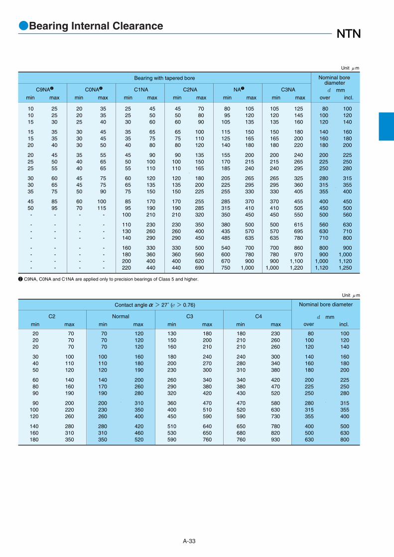
●Bearing Internal Clearance
A-33
120120120
160180190
200260280
310350400
420460520
80100120
140160180
200225250
280315355
400500630
100120140
160180200
225250280
315355400
500630800
130150160
180200230
260290320
360400450
510530590
180200210
240270300
340380420
470510590
640650760
230260260
300340380
420470520
580630730
780820930
202020
304050
608090
90100120
140160180
707070
100110120
140160190
200220260
280310350
707070
100110120
140170190
200230260
280310350
180210210
240280310
340380430
470520590
650680760
Nominal bore diameter
d mm
Contact angleα> 27˚ (e > 0.76)
C2 Normal C3 C4
over incl.min maxmin maxmin maxmin max
Unit μm
202025
303030
354040
454550
6070-
- - -
- - - -
353540
454550
556565
757590
100115
-
- - -
- - - -
455060
657580
90100110
120135150
170190210
230260290
330360400440
101015
151520
202525
30 3035
4550-
- - -
- - - -
252530
353540
455055
606575
8595-
- - -
- - - -
708090
100110120
135150165
180 200225
255285320
350400450
500560620690
8095
105
115125140
155170185
205 225255
285315350
380435485
540600670750
80100120
140160180
200225250
280 315355
400450500
560630710
800900
1,0001,120
100120140
160180200
225250280
315355400
450 500
560
630710800
9001,0001,1201,250
252530
353540
455055
606575
8595
100
110130140
160180200220
455060
657580
90100110
120135150
170190210
230260290
330360400440
125145160
180200220
240265295
325 360405
455505550
615695780
860970
1,1001,220
105120135
150165180
200215240
265 295330
370410450
500570635
700780900
1,000
105120135
150165180
200215240
265 295330
370410450
500570635
700780900
1,000
Nominal bore diameter d mm
Bearing with tapered bore
C9NA2 C0NA2 C1NA C2NA NA1 C3NA
Unit μm
2 C9NA, C0NA and C1NA are applied only to precision bearings of Class 5 and higher.
over incl.min maxmin maxmin maxmin maxmin maxmin max

●Bearing Internal Clearance
A-34
Contact angleα<12°(e<0.32)
5585
140
200260340
430- -
165230320
420520640
780- -
63.5127 203.2
304.8406.4508
609.6711.2762
127 203.2304.8
406.4508 609.6
711.2762 914.4
290320370
660710790
1,120- -
400470550
880970
1,090
1,470- -
400470550
880970
1,090
1,470- -
510620730
1,1001,2301,390
1,820- -
510620730
1,1001,2301,390
1,820- -
620770910
1,3201,4901,690
2,170- -
1 Nominal bore diameter d mm C2 Normal C3 C4
over incl. min max min max min max min max
1 Nominal bore diameter is the minimum size among the same series.
Note: This table shows NTN standard clearances.
Unit μm
Table 5.8 Axial internal clearance of double row and duplex tapered roller bearings (inch series)Table 5.8 (1) contact angle αα<<12˚
12°≦ Contact angleα<15°(0.32≦ e<0.40)
4570
120
160210280
350420520
135190270
340420530
640750890
63.5127 203.2
304.8406.4508
609.6711.2762
127 203.2304.8
406.4508 609.6
711.2762 914.4
240270310
550590650
930990
1,070
330390460
730800900
1,2201,3201,440
330390460
730800900
1,2201,3201,440
420510610
9101,0101,150
1,5101,6501,810
420510610
9101,0101,150
1,5101,6501,810
510630760
1,0901,2201,400
1,8001,9802,180
1 Nominal bore diameter d mm C2 Normal C3 C4
over incl. min max min max min max min max
1 Nominal bore diameter is the minimum size among the same series.
Note: This table shows NTN standard clearances.
Unit μmTable 5.8 (2) 12˚≦≦ contact angleαα<<15°°
15°≦ Contact angleα<20°(0.40≦ e<0.55)
355590
130170220
280340410
105155210
270340420
510600700
63.5127 203.2
304.8406.4508
609.6711.2762
127 203.2304.8
406.4508 609.6
711.2762 914.4
190210240
440470520
740780850
260310360
580640720
9701,0401,140
260310360
580640720
9701,0401,140
330410480
720810920
1,2001,3001,430
330410480
720810920
1,2001,3001,430
400510600
860980
1,120
1,4301,5601,720
1 Nominal bore diameter d mm C2 Normal C3 C4
over incl. min max min max min max min max
1 Nominal bore diameter is the minimum size among the same series.
Note: This table shows NTN standard clearances.
Unit μmTable 5.8 (3) 15˚≦≦ contact angleαα<<20°°

●Bearing Internal Clearance
A-35
20°≦ Contact angleα<30°(0.55≦ e<0.87)
304070
95120160
210250300
80110160
195240310
380440520
63.5127 203.2
304.8406.4508
609.6711.2762
127 203.2304.8
406.4508 609.6
711.2762 914.4
140160180
320350380
540580630
190230270
420470530
710770850
190230270
420470530
710770850
240300360
520590680
880960
1,070
240300360
520590680
880960
1,070
290370450
620710830
1,0501,1501,290
1 Nominal bore diameter d mm C2 Normal C3 C4
over incl. min max min max min max min max
1 Nominal bore diameter is the minimum size among the same series.
Note: This table shows NTN standard clearances.
Unit μmTable 5.8 (4) 20˚≦≦ contact angleαα<<30°°
30°≦ Contact angleα(0.87≦e)
152545
6080
100
130160190
5070
100
130160200
250290330
63.5127 203.2
304.8406.4508
609.6711.2762
127 203.2304.8
406.4508 609.6
711.2762 914.4
90100110
200220
-
- - -
125145170
270300
-
- - -
125145170
270300
-
- - -
160190230
340380
-
- - -
160190230
340380
-
- - -
200240290
410460
-
- - -
1 Nominal bore diameter d mm C2 Normal C3 C4
over incl. min max min max min max min max
1 Nominal bore diameter is the minimum size among the same series.
Note: This table shows NTN standard clearances.
Unit μmTable 5.8 (5) 30˚≦≦ contact angleαα

A-36
●Bearing Internal Clearance
354050
606570
8090
100
110120 130
140140150
170190210
230260290
320350400450
607595
110120130
140150170
190200 220
240260280
310350390
430480530
580640720810
80100120
140160180
200225250
280315355
400450500
560630710
800900
1,000
1,1201,2501,4001,600
100120140
160180200
225250280
315355400
450500560
630710800
9001,0001,120
1,2501,4001,6001,800
100120145
170180200
220240260
280310 340
370410440
480530580
650710780
860950
1,0601,180
607595
110120130
140150170
190200 220
240260280
310350390
430480530
580640720810
135160190
220240260
290320350
370410 450
500550600
650700770
860930
1,020
1,1201,2401,3801,550
100120145
170180200
220240260
280310 340
370410440
480530580
650710780
860950
1,0601,180
135160190
220240260
290320350
370410 450
500550600
650700770
860930
1,020
1,1201,2401,3801,550
180210240
280310340
380420460
500550600
660720780
850920
1,010
1,1201,2201,330
1,4601,6201,8002,000
180210240
280310340
380420460
500550600
660720780
850920
1,010
1,1201,2201,330
1,4601,620
- -
225260300
350390430
470520570
630690750
820900
1,000
1,1001,1901,300
1,4401,5701,720
1,8702,080
- -
Nominal bore diameter
d mm
Bearing with cylindrical bore
C2 Normal C3 C4 C5
over incl. min max min max min max min max min max
Note: This table shows NTN standard clearances where "d>1,000mm".
Table 5.9 Radial internal clearance of spherical roller bearings

A-37
●Bearing Internal Clearance
110135160
180200220
250270300
330360400
440490540
600670750
840930
1,030
1,1201,2301,3501,500
80100120
140160180
200225250
280315355
400450500
560630710
800900
1,000
1,1201,2501,4001,600
100120140
160180200
225250280
315355400
450500560
630710800
9001,0001,120
1,2501,4001,6001,800
140170200
230260290
320350390
430470520
570630680
760850960
1,0701,1901,300
1,4201,5601,7201,920
180220260
300340370
410450490
540590650
720790870
9801,0901,220
1,3701,5201,670
1,8302,0002,2002,400
230280330
380430470
520570620
680740820
9101,0001,100
1,2301,3601,500
1,6901,8602,050
2,2502,470
- -
556580
90100110
120140150
170190 210
230260290
320350390
440490530
570620680750
80100120
130140160
180200220
240270300
330370410
460510570
640710770
830910
1,0001,110
80100120
130140160
180200220
240270300
330370410
460510570
640710770
830910
1,0001,110
110135160
180200220
250270300
330360400
440490540
600670750
840930
1,030
1,1201,2301,3501,500
140170200
230260290
320350390
430470520
570630680
760850960
1,0701,1901,300
1,4201,5601,7201,920
180220260
300340370
410450490
540590650
720790870
9801,0901,220
1,3701,5201,670
1,8302,000
- -
Nominal bore diameter
d mm
Bearing with tapered bore
C2 Normal C3 C4 C5
Unit μm
over incl.min maxmin maxmin maxmin maxmin max

●Lubrication
6. Lubrication
6.1 Lubrication of rolling bearings
The purpose of bearing lubrication is to prevent directmetallic contact between the various rolling and slidingelements. This is accomplished through the formation of athin oil (or grease) film on the contact surfaces. Forrolling bearings, lubrication also has the followingadvantages:
(1) Friction and wear reduction(2) Friction heat dissipation(3) Prolonged bearing life(4) Prevention of rust(5) Protection against harmful elements
In order to achieve the above effects, the most effectivelubrication method for the operating conditions must beselected. Also, a good quality, reliable lubricant must beselected. In addition, an effectively designed sealingsystem that prevents the intrusion of damaging elements
A-38
Friction loss
Fric
tion
loss
Oil volume
EDCBA
Tem
pera
ture
incr
ease
Temperatureincrease
great
high
high
Fig. 6.1
(dust, water, etc.) into the bearing interior, removes dustand other impurities from the lubricant, and prevents thelubricant from leaking to the outside, is also arequirement.
Almost all rolling bearings use either grease or oillubrication methods, but in some special applications, asolid lubricant such as molybdenum disulfide or graphitemay be used.
Fig. 6.1 shows the relationship between oil volume,friction loss, and bearing temperature. Table 6.1 detailsthe characteristics of this relationship.
6.2 Characteristics of grease and oil lubricants Grease and oil are the two general choices for
lubrication: it is important to select lubricant with care.Please contact NTN Engineering when selecting alubricant.The characteristics are show in table 6.2.
Table 6.1 Oil volume, friction loss, bearing temperature (See Fig. 6.1)
Range Characteristics Lubrication method
When oil volume is extremely low,direct metallic contact occurs in placesbetween the rolling elements andraceway surfaces. Bearing abrasionand seizing occur.
A thin oil film develops over allsurfaces, friction is minimal andbearing temperature is low.
As oil volume increases, heat buildupis balanced by cooling.
Regardless of oil volume, temperatureincreases at a fixed rate.
As oil volume increases, coolingpredominates and bearing temperaturedecreases.
A
B
C
D
E
ーーー
Grease lubrication,oil mist,air-oil lubrication
Circulatinglubrication
Circulatinglubrication
Forced circulationlubrication,Oil jet lubrication
MethodConcern
Greaselubrication Oil lubrication
Handling
Reliability
Cooling effect
Seal structure
Power loss
Environment contamination
High speed rotation
◎
○
×
○
○
○
×
△
◎
○
△
○
△
○
(Circulation necessary)
◎: Very good ○:Good △:Fair ×:Poor
Table 6.2 Comparison of grease lubrication and oillubrication characteristics
6.3 Grease lubricationGrease type lubricants are relatively easy to handle and
require only the simplest sealing devices–for thesereasons, grease is the most widely used lubricant forrolling bearings.
6.3.1 Types and characteristics of greaseLubricating greases are composed of either a mineral
oil base or a synthetic oil base. To this base a thickenerand other additives are added. The properties of allgreases are mainly determined by the kind of base oilused and by the combination of thickening agent andvarious additives.
Standard greases and their characteristics are listed inTable 6.3. As performance characteristics of even thesame type of grease will vary widely from brand to brand,it is best to check the manufacturers' data when selectinga grease.

A-39
●Lubrication
Lithium grease Sodium grease(fiber grease)
Calcium compoundbase grease
Thickener
Grease name
Base oil
Dropping point ˚C
Mechanical stability
Pressure resistance
Water resistance
Applications
Li soap Na soap Ca+Na soapCa+Li soap
Mineral oil
170 ~ 190
-30 ~ +130
Excellent
Good
Good
Diester oil
170 ~ 190
-50 ~ +130
Good
Good
Good
Silicone oil
200 ~ 250
-50 ~ +160
Good
poor
Good
Mineral oil
150 ~ 180
-20 ~ +130
Excellent ~ Good
Good
Good ~ poor
Mineral oil
150 ~ 180
-20 ~ +120
Excellent ~ Good
Excellent ~ Good
Good ~ poor
Widest range ofapplications.
Grease used in alltypes of rollingbearings.
Excellent lowtemperature andwear characteristics.
Suitable for smallsized and miniaturebearings.
Suitable for highand lowtemperatures.
Unsuitable for heavyload applications dueto low oil filmstrength.
Some emulsificationwhen water isintroduced.
Excellentcharacteristics atrelatively hightemperatures.
Excellent pressureresistance andmechanical stability.
Suitable forbearings receivingshock loads.
Aluminum grease Non-soap base greaseThickener
AI soap Bentone, silica gel, urea, carbon black,fluorine compounds, etc.
Mineral oil
70 ~ 90
-10 ~ +80
Good ~ poor
Good
Good
Mineral oil
250 or above
-10 ~ +130
Good
Good
Good
Synthetic oil
250 or above
-50 ~ +200
Good
Good
Good
Excellent viscositycharacteristics.
Suitable forbearings subjectedto vibrations.
Can be used in a wide range of low tohigh temperatures. Shows excellent heatresistance, cold resistance, chemicalresistance, and other characteristicswhen matched with a suitable base oiland thickener.
Grease used in all types of rolling bearings.
Thickener
Grease name
Base oil
Dropping point ˚C
Mechanical stability
Pressure resistance
Water resistance
Applications
Operatingtemperature range ˚C
Operatingtemperature range ˚C
Table 6.3 Grease varieties and characteristics

●Lubrication
6.3.6 Mixing of greasesWhen greases of different kinds are mixed together, the
consistency of the greases will change (usually softer), theoperating temperature range will be lowered, and otherchanges in characteristics will occur. As a general rule,greases with different bases oil, and greases with differentthickener agents should never be mixed.
Also, greases of different brands should not be mixedbecause of the different additives they contain.
However, if different greases must be mixed, at leastgreases with the same base oil and thickening agentshould be selected. But even when greases of the samebase oil and thickening agent are mixed, the quality of thegrease may still change due to the difference in additives.For this reason, changes in consistency and other qualitiesshould be checked before being applied.
6.3.7 Amount of greaseThe amount of grease used in any given situation will
depend on many factors relating to the size and shape ofthe housing, space limitations, bearing's rotating speedand type of grease used.
As a general rule, housings and bearings should beonly filled from 30% to 60% of their capacities.
A-40
Table 6.5 Bearings space ratio K
Bearing type Retainer type K
Ball bearings
NU-type cylindrical roller bearings
N-type cylindrical roller bearings
Tapered roller bearings
Spherical roller bearings
2
3
1
1 Remove 160 series2 Remove NU4 series3 Remove N4 series
Pressed retainer
Pressed retainer Machined retainer
Pressed retainer Machined retainer
Pressed retainer
Pressed retainer Machined retainer
61
5036
5537
46
3528
6.3.2 Base oilNatural mineral oil or synthetic oils such as diester oil,
silicone oil and fluorocarbon oil are used as grease baseoils.
Mainly, the properties of any grease are determined bythe properties of the base oil. Generally, greases with alow viscosity base oil are best suited for low temperaturesand high speeds; while greases made from high viscositybase oils are best suited for heavy loads.
6.3.3 Thickening agentsThickening agents are compounded with base oils to
maintain the semi-solid state of the grease. Thickeningagents consist of two types of bases, metallic soaps andnon-soaps. Metallic soap thickeners include: lithium,sodium, calcium, etc.
Non-soap base thickeners are divided into two groups;inorganic (silica gel, bentonite, etc.) and organic (poly-urea, fluorocarbon, etc.).
The various special characteristics of a grease, such aslimiting temperature range, mechanical stability, waterresistance, etc. depend largely on the type of thickeningagent used. For example, a sodium based grease isgenerally poor in water resistance properties, whilegreases with bentone, poly-urea and other non-metallicsoaps as the thickening agent are generally superior inhigh temperature properties.
6.3.4 AdditivesVarious additives are added to greases to improve
various properties and efficiency. For example, there areanti-oxidants, high-pressure additives (EP additives), rustpreventives, and anti-corrosives.
For bearings subject to heavy loads and/or shock loads,a grease containing high-pressure additives should beused. For comparatively high operating temperatures orin applications where the grease cannot be replenishedfor long periods, a grease with an oxidation stabilizer isbest to use.
6.3.5 ConsistencyThe consistency of a grease, i.e. the stiffness and
liquidity, is expressed by a numerical index.
The NLGI values for this index indicate the relativesoftness of the grease; the larger the number, the stifferthe grease. The consistency of a grease is determinedby the amount of thickening agent used and the viscosityof the base oil. For the lubrication of rolling bearings,greases with the NLGI consistency numbers of 1, 2, and3 are used.
General relationships between consistency andapplication of grease are shown in Table 6.4.
Table 6.4 Consistency of grease
NLGIConsis-
tency No.
JIS (ASTM)Worked
penetrationApplications
0
1
2
3
4
For centralized greasing use
For centralized greasing use
For general use and sealed bearing use
For general and high temperature use
For special use
355~385
310~340
265~295
220~250
175~205

A-41
●Lubrication
Where speeds are high and temperature rises need tobe kept to a minimum, a reduced amount of greaseshould be used. Excessive amount of grease causetemperature rise which in turn causes the grease tosoften and may allow leakage. With excessive grease fillsoxidation and deterioration may cause lubricatingefficiency to be lowered.
6.4 Solid grease (for bearings with solid grease)"Solid grease" is a lubricant composed mainly of
lubricating grease and ultra-high polymer polyethylene.Solid grease has the same viscosity as grease at normaltemperature, but by applying a special heat treatmentprocess, this special grease solidifies retaining a largeproportion of the lubricant within the bearing. The result ofthis solidification is that the grease does not easily leakfrom the bearing, even when the bearing is subjected tostrong vibrations or centrifugal force.
Bearings with solid grease are available in two types:the spot-pack type in which solid grease is injected intothe retainer, and the full-pack type in which all emptyspace around the rolling elements is filled with solidgrease.
Spot-pack solid grease is standard for deep groove ballbearings, small diameter ball bearings, and bearing units.Full-pack solid grease is standard for self-aligning ballbearings, self-aligning roller bearings, and needle rollerbearings.
Primary advantages:(1) Clean working environment with minimal grease
leakage(2) Low bearing torque with spot-pack type solid grease
For more details, please refer to the NTN special catalogfor Solid grease bearings.
Fig. 6.3 Deep groove ball bearing with spot-pack solid grease (Z shield)(Standard for deep groove ball bearings)
Fig. 6.4 Self-aligning roller bearing with full-pack solid grease(Standard for self-aligning roller bearings)
Solid grease
Solid grease

●Lubrication
6.5 Oil lubricationOil lubrication is suitable for applications that require
bearing-generated heat or heat applied to the bearingfrom other sources be carried away from the bearing and
A-42
Lubrication method Example
¡In this method, the required minimum amount of lubricating oil is measured and fed to each bearing at ideal intervals using compressed air.
¡With fresh lubricating oil constantly being fed to the bearing, and with the cooling effect of the compressed air, bearing temperature rise can be minimized.
¡Because the required oil quantity is infinitesimal, the working environment can be kept clean. Air-oil lubrication units
are available from NTN.
Lubrication method Example
(Air-oil lubrication)
¡This method lubricates by injecting oil under high pressure directly into the side of the bearing. This is a reliable system for high speed, high temperature or otherwise severe conditions.
¡Used for lubricating the bearings in jet engines, gas turbines, and other high speed equipment.
¡Under-race lubrication for machine tools is one example of this type of lubrication.
(Oil jet lubrication)
¡Using pressurized air, lubricating oil is atomized before passing through the bearing.
¡Due to the low lubricant resistance, this method is well suited to high speed applications.
(Oil mist lubrication)
¡In this method, a partially submerged disc rotates and pulls oil up into a reservoir from which it then drains down through the bearing, lubricating it.
(Disc lubrication)
¡In this method, oil is collected above the bearing and allowed to drip down into the housing where it becomes a lubricating mist as it strikes the rolling elements. Another version allows only slight amounts of oil to pass through the bearing.
¡Used at relatively high speeds for light to moderate load applications.
¡In most cases, oil volume is a few drops per minute.
(Drip lubrication)
¡Used for bearing cooling applications or for automatic oil supply systems in which the oil supply is centrally located.
¡One of the advantages of this method is that oil cooling devices and filters to maintain oil purity can be installed within the system.
¡In order for oil to thoroughly lubricate the bearing, oil inlets and outlets must be provided on opposite sides of the bearing.
(Circulating lubrication)
¡In this method, an impeller or similar device mounted on the shaft draws up oil and sprays it onto the bearing. This method can be used at considerably high speeds.
(Oil spray lubrication)
¡Oil bath lubrication is the most generally used method of lubrication and is widely used for low to moderate rotation speed applications.
¡For horizontal shaft applications, oil level should be maintained at approximately the center of the lowest rolling element, according to the oil gauge, when the bearing is at rest. For vertical shafts at low speeds, oil level should be maintained at 50 - 80% submergence of the rolling elements.
(Oil bath lubrication)
Mistseparator
Air
Air filter
Reservoir (level switch)
Air oil line
Pressure switch
Air Nozzle
TimerSolenoid valve
T
Oil
Oil supply plug
Oil supply plug
Oil exhaust plug
Oil exhaustplug
Oil exhaustplug
Oil exhaustplug
Oil supply plug
Table 6.6 Oil lubrication methods
dissipated to the outside.Table 6.6 shows the mainmethods of oil lubrication.

A-43
●Lubrication
6.5.1 Selection of lubricating oilUnder normal operating conditions, spindle oil, machine
oil, turbine oil, and other mineral oils are widely used forthe lubrication of rolling bearings. However, fortemperatures above 150˚C or below -30˚C, synthetic oilssuch as diester oil, silicone oil, and fluorocarbon oil areused.
For lubricating oils, viscosity is one of the mostimportant properties and it determines an oil’s lubricatingefficiency. If viscosity is too low, formation of the oil filmwill be insufficient, and damage will occur to the loadcarrying surfaces of the bearing. If viscosity is too high,viscous resistance will also be great and result intemperature increases and friction loss. In general, forhigher speed applications a lower viscosity oil should beused; for heavier load applications, a higher viscosity oilshould be used.
In regard to operating temperature and lubrication,Table 6.7 lists the required oil viscosity for different typesof rolling bearings. Fig. 6.3 is an oil viscosity–operatingtemperature comparison chart for the purpose ofselecting a lubrication oil with viscosity characteristicsappropriate to an application.
Table 6.8 lists the selection standards for lubricating oilviscosity with reference to bearing operating conditions.
6.5.2 Oil quantityIn forced oil lubrication systems, the heat radiated away
by the housing and surrounding parts plus the heatcarried away by the lubricating oil is approximately equalto the amount of heat generated by the bearing and othersources.
For standard housing applications, the quantity of oilrequired can be found by formula (6.2).
Q=K・q ……………………………… (6.2)where,
Q: Quantity of oil for one bearing cm3/min.K: Allowable oil temperature rise factor (Table 6.9)q : Minimum oil quantity cm3/min. (Fig. 6.4)
Because the amount of heat radiated will varyaccording to the type of housing, for actual operation it isadvisable that the quantity of oil calculated by formula(6.2) be multiplied by a factor or 1.5 or 2.0. Then, theamount of oil can be adjusted to correspond to actualoperating conditions.
Bearing operatingtemperature
˚C
Up to allowable speed limiting
dn-valueLubricating oil ISO viscosity grade (VG)
Normal load Heavy load or shock loadSuitable bearing
-30~ 0 22,32 46 All types
0~ 60
60~100
100 ~150
0~ 60
60~100
15,000 Up to
15,000 ~80,000
80,000 ~150,000
150,000~500,000
15,000 Up to
15,000 ~80,000
80,000 ~150,000
150,000~500,000
Up to allowable speed limiting
Up to allowable speed limiting
Up to allowable speed limiting
46,68
32,46
22,32
100
68
32
22,32
220
150
100,150
68
10
150
100
68
32
All types
All types
All types but thrust ball bearings
Single row radial ball bearings, cylindrical roller bearings
All types
All types
All types but thrust ball bearings
Single row radial ball bearings, cylindrical roller bearings
All types
Self-aligning roller bearings
320
46,68
150
Notes: 1. Applied when lubrication method is either oil bath or circulating lubrication. 2. Please consult NTN Engineering in cases where operating conditions fall outside the range covered by this table.
Ball bearings, Cylindrical roller bearings,Needle roller bearings
Self-aligning roller bearings, Tapered rollerbearings, Needle roller thrust bearings
Self-aligning roller thrust bearings
Bearing type Dynamic viscosity mm2 /s
13
20
30
Table 6.7 Required lubricating oil viscosity for bearings
Table 6.8 Selection standards for lubricating oils (reference)
3,0002,000
1,000
500
300200
100
50
30
2015
10
8
6
5
4
3
- 30 - 20 0- 10 10 20 30 40 50 60 70 80 90 100 110 120 130 140 150 160
1 : ISO VG 320
7 : ISO VG 15
2 : ISO VG 1503 : ISO VG 684 : ISO VG 465 : ISO VG 326 : ISO VG 22
Temperature ˚C
Vis
cosi
ty m
m2 /s
1
2
34
56
7
Fig. 6.3 Relation between lubricating oil viscosity andtemperature

●Lubrication
A-44
Fig. 6.4 Oil quantity guidelines
Table 6.9 Factor K
KExpelled oil temp minussupplied oil temp ˚C
10 1.5
15 1
20 0.75
25 0.6
140
160
1008060
200
40
300200
30,000
20,000
100 10,000
70 7,000
60 6,000
40 4,000
30 3,000
20 2,000
15 1,500
10 1,000
8 8
00
6 6
00
4 4
00
2 2
00
1
2
3
4
56
810
15
2030
40
100
200
300
400
500
600
700
800
900
1,000
1,100
1,200
Shaftdiameter
dmm
Oil quantity qcm3/min
kN kgfLoad Pr
dn×
104
Self-aligning roller bearingsTapered roller bearings
Angular contact ball bearingsDeep groove ball bearings,
Cylindrical roller bearings
Bearing type
6.5.3 Relubrication intervalsThe intervals at which lubricating oil should be changed
varies depending upon operating conditions, oil quantity,and type of oil used. In general, for oil bath lubricationwhere the operating temperature is 50˚C or less, oilshould be replaced once a year. When the operatingtemperature is between 80˚C – 100˚C, oil should bereplaced at least every three months. For importantequipment, it is advisable that lubricating efficiency andoil purity deterioration be checked regularly to determinewhen oil replacement is necessary.
Furthermore, if it is assumed for calculation purposesthat no heat is radiated by the housing, and that allbearing heat is removed by the oil, then the value in Fig.6.3 for shaft diameter, d = 0, regardless of actual shaftdiameter.
――――――――――――――――――――――――――――――――――――(Example) For tapered roller bearing 30220Umounted on a flywheel shaft with a radial load of 9.5kN (969 kgf), operating at 1,800 min-1, what is theamount of lubricating oil required to keep the bearingtemperature rise below 15˚C.――――――――――――――――――――――――――――――――――――
d = 100 mm,dn = 100×1,800=18×104
From Fig. 6.4 q = 180cm3 / minAssume the bearing temperature is approximately
equal to the expelled oil temperature,from Table 6.9, since K= 1
Q=1×180=180cm3 / min

7.1 Raceway and rolling element materialsWhile the contact surfaces of a bearing's raceways and
rolling elements are subjected to repeated heavy stress,they still must maintain high precision and rotationalaccuracy. To accomplish this, the raceways and rollingelements must be made of a material that has highhardness, is resistant to rolling fatigue, is wear resistant,and has good dimensional stability. The most commoncause of fatigue cracking in bearings is the inclusion ofnon-metallic impurities in the steel. By using pure materialslow in these non-metallic impurities, the rolling fatigue life ofthe bearing is lengthened. For all NTN bearings, steel low in oxygen content and
non-metallic impurities, then refined by a vacuumdegassing process as well as outside hearth smelting, isused. For bearings requiring especially high reliability andlong life, steels of even higher in purity, such as vacuumsmelted steel (VIM, VAR, CEVM) and electro-slag meltedsteel (ESR), are used.
1) High/mid carbon alloy steelIn general, steel varieties which can be hardened not just
on the surface but also deep hardened by the so-called"through hardening method" are used for the raceways androlling elements of bearings. Foremost among these is highcarbon chromium bearing steel, which is widely used. Forlarge type bearings and bearings with large cross sectionaldimensions, induction hardened bearing steel incorporatingmanganese or molybdenum is used. Also in use is mid-carbon chromium steel incorporating silicone andmanganese, which gives it hardening propertiescomparable to high carbon chromium steel.
2) Case hardened (carburized) steelBecause of its combination of a hard surface layer which
has been carburized and hardened to an appropriatedepth, and a relatively pliable inner core, case hardenedsteel has excellent efficiency against shock loads. NTNuses case hardened steel for almost all of its tapered rollerbearings. In terms of case hardened steel for NTN's otherbearings, chromium steel and chrome molybdenum steelare used for small to medium sized bearings, and nickelchrome molybdenum steel is used for large sized bearings.
3) Heat resistant bearing steelWhen bearings made of ordinary high carbon chromium
steel which have undergone standard heat treatment areused at temperatures above 120˚C for long durations,unacceptably large dimensional changes can occur. Forthis reason, a dimension stabilizing treatment (TStreatment) has been devised for very high temperatureapplications. Through application of this dimensionstabilizing treatment, shortening of rolling fatigue life due todecreases in bearing hardness at high temperatures canbe avoided. (refer to page insert A-6 1.3.2)
For standard high temperature bearings used attemperatures from 150˚C – 200˚C, the addition of siliconeto the steel improves heat resistance and results in a
A-45
●Bearing Materials
7. Bearing Materials
bearing with excellent rolling fatigue life with minimaldimensional change or softening at high temperatures. A variety of heat resistant steels are also incorporated in
bearings to minimize softening and dimensional changeswhen used at high temperatures. Two of these are highspeed molybdenum steel and high speed tungsten steel.For bearings requiring heat resistance in high speedapplications, there is also heat resistant case hardeningmolybdenum steel.
4) Corrosion resistant bearing steelFor applications requiring high corrosion resistance,
stainless steel is used. To achieve this corrosion resistancea large proportion of the alloying element chrome is addedto martensite stainless steel.
5) Induction hardened steelBesides the use of surface hardening steel, induction
hardening is also utilized for bearing raceway surfaces, andfor this purpose mid-carbon steel is used for its lowercarbon content instead of through hardened steel. Forinduction hardening of the deep layers required for largerbearings and bearings with large surface dimensions, mid-carbon steel is fortified with chrome and molybdenum.
6) Other bearing materialsFor ultra high speed applications and applications
requiring very high level corrosion resistance, ceramicbearing materials such as Si3N4 are also available.
7.2 Cage materialsBearing cage materials must have the strength to
withstand rotational vibrations and shock loads. Thesematerials must also have a low friction coefficient, be lightweight, and be able to withstand bearing operationtemperatures. For small and medium sized bearings, pressed cages of
cold or hot rolled steel with a low carbon content of approx.0.1% are used. However, depending on the application,austenitic stainless steel is also used.
For large bearings, machined cages of machinestructural carbon steel or high tensile cast brass are widelyused, although aluminum alloy and other material cagesare also available.
For aircraft engine bearings, high tensile brass, mid-carbon nickel, chrome, or molybdenum steel is used afterundergoing various heat treatments and high temperaturetempering. The sliding properties of these materials mayalso be enhanced when silver plated.
Injection molded plastic cages are now widely used: mostare made from fiberglass reinforced heat resistantpolyamide resin. Plastic cages are light weight, corrosionresistant and have excellent damping and slidingproperties. Heat resistant polyamide resins now enable theproduction of cages that perform well in applicationsranging between -40˚C – 120˚C. However, they are notrecommended for use at temperatures exceeding 120˚C.

A-46
MEMO

General Bearings

B-2
INDEX OF BEARING TABLES
Deep Groove Ball Bearings ⋯⋯⋯⋯⋯⋯⋯⋯⋯⋯⋯⋯⋯⋯⋯⋯⋯⋯⋯⋯B- 5
Angular Contact Ball Bearings ⋯⋯⋯⋯⋯⋯⋯⋯⋯⋯⋯⋯⋯⋯⋯⋯⋯⋯B-15
Angular contact ball bearings (single, duplex) ⋯⋯⋯⋯⋯⋯⋯⋯⋯⋯⋯⋯⋯⋯⋯B-18
Double row angular contact ball bearings ⋯⋯⋯⋯⋯⋯⋯⋯⋯⋯⋯⋯⋯⋯⋯⋯⋯B-32
Cylindrical Roller Bearings ⋯⋯⋯⋯⋯⋯⋯⋯⋯⋯⋯⋯⋯⋯⋯⋯⋯⋯⋯⋯B-37
Single row cylindrical roller bearings ⋯⋯⋯⋯⋯⋯⋯⋯⋯⋯⋯⋯⋯⋯⋯⋯⋯⋯⋯B-40
Multi-row cylindrical roller bearings ⋯⋯⋯⋯⋯⋯⋯⋯⋯⋯⋯⋯⋯⋯⋯⋯⋯⋯⋯⋯B-56
4-row cylindrical roller bearings ⋯⋯⋯⋯⋯⋯⋯⋯⋯⋯⋯⋯⋯⋯⋯⋯⋯⋯⋯⋯⋯B-64
SL type cylindrical roller bearings ⋯⋯⋯⋯⋯⋯⋯⋯⋯⋯⋯⋯⋯⋯⋯⋯⋯⋯⋯⋯B-80
SL type cylindrical roller bearings for sheaves ⋯⋯⋯⋯⋯⋯⋯⋯⋯⋯⋯⋯⋯⋯⋯B-84
Tapered Roller Bearings ⋯⋯⋯⋯⋯⋯⋯⋯⋯⋯⋯⋯⋯⋯⋯⋯⋯⋯⋯⋯⋯B- 89
Single row tapered roller bearings (Metric system sizes) ⋯⋯⋯⋯⋯⋯⋯⋯⋯⋯B- 96
Single row tapered roller bearings (Inch system sizes) ⋯⋯⋯⋯⋯⋯⋯⋯⋯⋯⋯B-106
Double row tapered roller bearings (outside direction) (Metric system sizes) ⋯B-124
Double row tapered roller bearings (outside direction) (Inch system sizes) ⋯⋯B-140

B-3
Double row tapered roller bearings (inside direction) (Metric system sizes) ⋯⋯B-152
Double row tapered roller bearings (inside direction) (Inch system sizes) ⋯⋯⋯B-162
Double row steep slope tapered roller bearings (outside direction) ⋯⋯⋯⋯⋯⋯B-170
Double row steep slope tapered roller bearings (inside direction) ⋯⋯⋯⋯⋯⋯B-172
Four row tapered roller bearings ⋯⋯⋯⋯⋯⋯⋯⋯⋯⋯⋯⋯⋯⋯⋯⋯⋯⋯⋯⋯B-180
Sealed four row tapered roller bearings ⋯⋯⋯⋯⋯⋯⋯⋯⋯⋯⋯⋯⋯⋯⋯⋯⋯B-200
Spherical Roller Bearings⋯⋯⋯⋯⋯⋯⋯⋯⋯⋯⋯⋯⋯⋯⋯⋯⋯⋯⋯⋯⋯B-203
Thrust Bearings⋯⋯⋯⋯⋯⋯⋯⋯⋯⋯⋯⋯⋯⋯⋯⋯⋯⋯⋯⋯⋯⋯⋯⋯⋯⋯⋯B-227
Thrust bearings ⋯⋯⋯⋯⋯⋯⋯⋯⋯⋯⋯⋯⋯⋯⋯⋯⋯⋯⋯⋯⋯⋯⋯⋯⋯⋯⋯⋯B-230
Thrust roller bearings ⋯⋯⋯⋯⋯⋯⋯⋯⋯⋯⋯⋯⋯⋯⋯⋯⋯⋯⋯⋯⋯⋯⋯⋯⋯B-234
Tapered roller thrust bearings (single direction type) ⋯⋯⋯⋯⋯⋯⋯⋯⋯⋯⋯⋯B-240
Tapered roller thrust bearings (double direction type) ⋯⋯⋯⋯⋯⋯⋯⋯⋯⋯⋯B-244
Self-aligning roller thrust bearings ⋯⋯⋯⋯⋯⋯⋯⋯⋯⋯⋯⋯⋯⋯⋯⋯⋯⋯⋯⋯B-246

Deep Groove Ball Bearings

●Deep Groove Ball Bearings
1. Structure and Characteristics
A widely used bearing, the deep groove ball bearing takesits name from the track formed on both the inner and outerrings of the bearing. The bearings can sustain radial andaxial loads and the resultant forces of these loads and theyare suitable for high speed operation.
The dimensional table below represents the various cagemodels and special shapes. Drawing A is the pressed cage;
B-5
drawing B shows the machined cage; drawings C throughF show the position and shape of the notch on the inner ring;and drawing G shows a bearing with the key groove on theinner ring. Pressed cages are generally used, thoughmachined cages are used for larger sized bearings, orbearings for high speed rotation.
C D E F GA B
2. Dimensional Accuracy/Rotation Accuracy
Refer to Table 3.3 (Page A-12)
3. Recommended Fitting
Refer to Table 4.2 (Page A-24)
4. Bearing Internal Clearance
Refer to Table 5.2 (Page A-30)
5. Permissible slant angle
0.0006-0.003 radian
6. General Operating Cautions
Slippage between the balls and raceways may occurwhen bearings are operated under small loads (about Fr≦0.01Cor) and may cause smearing. This is most apparentwhen using large size deep groove ball bearings due to thelarge cage mass. Please consult NTN Engineering for furtherdetails.
Deep groove ball bearings drawing

B-6
●Deep Groove Ball Bearings
Boundary dimensions Basic load ratings Bearing Drawing1 Abutment and Massdynamic static dynamic static numbers No. fillet dimensions
mm kN kgf mm kgda Da ras
d D B rs min2
Cr Cor Cr Cor min max max (approx.)
1 Drawing details are shown in Page B-5.2 Smallest allowable dimension for chamfer dimension r.
d 100~140mm
B
r
r
φD φd
ra
φdaφDa
ra
0.0100.0200.0400.0700.100.150.200.300.400.50
0.180.200.240.270.290.320.350.380.410.44
1 0 0.56
2.462.141.831.611.481.351.251.131.051.00
Fa
FreX Y X Y
≦eFa
Cor
Fa
Fr>e
Equivalent bearing loaddynamicPr=XFr+YFa
staticPor=0.6Fr+0.5Fa
When Por<Fr use Por=Fr
125 13 1 19.6 21.2 2,000 2,160 6820 A 105 120 1 0.31140 20 1.1 41 39.5 4,200 4,050 6920 A 106.5 133.5 1 0.78150 16 1 35 36.5 3,600 3,750 16020 A 105 145 1 0.91150 24 1.5 60 54 6,150 5,500 6020 A 108 142 1.5 1.15180 34 2.1 122 93 12,500 9,450 6220 A 111 169 2 3.14215 47 3 173 141 17,600 14,400 6320 A 113 202 2.5 7
130 13 1 19.8 22 2,020 2,240 6821 A 110 125 1 0.33145 20 1.1 42.5 42 4,300 4,300 6921 A 111.5 138.5 1 0.81160 18 1 52 50.5 5,300 5,150 16021 A 110 155 1 1.2160 26 2 72.5 65.5 7,400 6,700 6021 A 114 151 2 1.59190 36 2.1 133 105 13,600 10,700 6221 A 116 179 2 3.7225 49 3 184 153 18,700 15,700 6321 A 118 212 2.5 8.05
140 16 1 24.9 28.2 2,540 2,880 6822 A 115 135 1 0.51150 20 1.1 43.5 44.5 4,450 4,550 6922 A 116.5 143.5 1 0.85170 19 1 57.5 56.5 5,850 5,800 16022 A 115 165 1 1.46170 28 2 82 73 8,350 7,450 6022 A 119 161 2 1.96200 38 2.1 144 117 14,700 11,900 6222 A 121 189 2 4.36240 50 3 205 179 20,900 18,300 6322 A 123 227 2.5 9.54
150 16 1 28.9 33 2,950 3,350 6824 A 125 145 1 0.55165 22 1.1 53 54 5,400 5,500 6924 A 126.5 158.5 1 1.15180 19 1 63 63.5 6,450 6,450 16024 A 125 175 1 1.56180 28 2 85 79.5 8,650 8,100 6024 A 129 171 2 2.07215 40 2.1 155 131 15,900 13,400 6224 A 131 204 2 5.15260 55 3 207 185 21,100 18,800 6324 A 133 247 2.5 12.4
165 18 1.1 37 41 3,750 4,200 6826 A 136.5 158.5 1 0.8180 24 1.5 65 67.5 6,650 6,850 6926 A 138 172 1.5 1.52200 22 1.1 80 79.5 8,150 8,100 16026 A 136.5 193.5 1 2.31200 33 2 106 101 10,800 10,300 6026 A 139 191 2 3.16230 40 3 167 146 17,000 14,900 6226 A 143 217 2.5 5.82280 58 4 229 214 23,400 21,800 6326 A 146 264 3 15.3
175 18 1.1 38.5 44.5 3,900 4,550 6828 A 146.5 168.5 1 0.85190 24 1.5 66.5 71.5 6,800 7,300 6928 A 148 182 1.5 1.62210 22 1.1 82 85 8,350 8,650 16028 A 146.5 203.5 1 2.45210 33 2 110 109 11,200 11,100 6028 A 149 201 2 3.35
100
105
110
120
130
140

B-7
B
r
r
φD φd
ra
φdaφDa
ra
0.0100.0200.0400.0700.100.150.200.300.400.50
0.180.200.240.270.290.320.350.380.410.44
1 0 0.56
2.462.141.831.611.481.351.251.131.051.00
Fa
FreX Y X Y
≦eFa
Cor
Fa
Fr>e
Equivalent bearing loaddynamicPr=XFr+YFa
staticPor=0.6Fr+0.5Fa
When Por<Fr use Por=Fr
Boundary dimensions Basic load ratings Bearing Drawing1 Abutment and Massdynamic static dynamic static numbers No. fillet dimensions
mm kN kgf mm kgda Da ras
d D B rs min2
Cr Cor Cr Cor min max max (approx.)
1 Drawing details are shown in Page B-5.2 Smallest allowable dimension for chamfer dimension r.
●Deep Groove Ball Bearings
d 140~180mm
250 42 3 166 150 17,000 15,300 6228 A 153 237 2.5 7.57300 62 4 253 246 25,800 25,100 6328 A 156 284 3 18.5
220 38 2.5 126 115 12,800 11,800 SC2951 B 157 208 2 5.07
190 20 1.1 47.5 55 4,850 5,600 6830 A 156.5 183.5 1 1.16210 28 2 85 90.5 8,650 9,200 6930 A 159 201 2 2.47225 24 1.1 96.5 101 9,850 10,300 16030 A 156.5 218.5 1 3.07225 35 2.1 126 126 12,800 12,800 6030 A 161 214 2 4.08230 35 2.5 120 118 12,300 12,100 SC3002 C 162 218 2 5.18230 35 2.5 120 118 12,300 12,100 SC3007 G 162 218 2 5.18270 45 3 176 168 18,000 17,100 6230 A 163 257 2.5 9.41320 65 4 274 284 28,000 28,900 6330 A 166 304 3 22
200 20 1.1 48.5 57 4,950 5,800 6832 A 166.5 193.5 1 1.23220 28 2 87 96 8,850 9,800 6932 A 169 211 2 2.61229.5 33 2.5 108 111 11,000 11,300 SC3209 B 172 218 2 4.35229.5 36 2.5 120 119 12,200 12,100 SC3207 B 172 218 2 4.75230 33 2.5 108 111 11,000 11,300 SC3210 B 172 218 2 4.39240 25 1.5 99 108 10,100 11,000 16032 A 168 232 1.5 3.64240 38 2.1 143 144 14,500 14,700 6032 A 171 229 2 5.05290 48 3 185 186 18,900 19,000 6232 A 173 277 2.5 11.7340 68 4 278 286 28,300 29,200 6332 A 176 324 3 26
215 22 1.1 60 70.5 6,100 7,200 6834 A 176.5 208.5 1 1.63230 28 2 86 95.5 8,750 9,750 6934 A 179 221 2 2.74260 28 1.5 119 128 12,100 13,100 16034 A 178 252 1.5 4.93260 42 2.1 168 172 17,200 17,600 6034 A 181 249 2 6.76310 52 4 212 223 21,700 22,800 6234 A 186 294 3 14.5360 72 4 325 355 33,500 36,000 6334 A 186 344 3 30.7
225 22 1.1 60.5 73 6,200 7,450 6836 B 186.5 218.5 1 2.03250 33 2 110 119 11,200 12,200 6936 B 189 241 2 4.76265 33 2.5 113 127 11,500 13,000 SC3605 B 192 253 2 6.08280 31 2 117 134 11,900 13,600 16036 A 189 271 2 6.49280 46 2.1 189 199 19,300 20,300 6036 A 191 269 2 8.8320 52 4 227 241 23,200 24,600 6236 A 196 304 3 15.1380 75 4 355 405 36,000 41,500 6336 A 196 364 3 35.6
140
145
150
160
170
180

B-8
●Deep Groove Ball Bearings
Boundary dimensions Basic load ratings Bearing Drawing1 Abutment and Massdynamic static dynamic static numbers No. fillet dimensions
mm kN kgf mm kgda Da ras
d D B rs min2
Cr Cor Cr Cor min max max (approx.)
1 Drawing details are shown in Page B-5.2 Smallest allowable dimension for chamfer dimension r.
d 190~260mm
B
r
r
φD φd
ra
φdaφDa
ra
0.0100.0200.0400.0700.100.150.200.300.400.50
0.180.200.240.270.290.320.350.380.410.44
1 0 0.56
2.462.141.831.611.481.351.251.131.051.00
Fa
FreX Y X Y
≦eFa
Cor
Fa
Fr>e
Equivalent bearing loaddynamicPr=XFr+YFa
staticPor=0.6Fr+0.5Fa
When Por<Fr use Por=Fr
240 24 1.5 73 88 7,450 9,000 6838 B 198 232 1.5 2.62260 33 2 113 127 11,500 13,000 6938 B 199 251 2 4.98269.5 33 2.5 117 134 11,900 13,600 SC3805 G 202 258 2 5.87290 31 2 134 156 13,700 15,900 16038 A 199 281 2 6.77290 46 2.1 197 215 20,100 21,900 6038 A 201 279 2 9.18340 55 4 255 281 26,000 28,700 6238 A 206 324 3 18.2400 78 5 355 415 36,000 42,500 6338 A 210 380 4 41
270 35 2.5 130 147 13,300 15,000 SC3904 B 207 258 2 5.94
250 24 1.5 74 91.5 7,550 9,300 6840 B 208 242 1.5 2.73280 38 2.1 157 168 16,000 17,100 6940 B 211 269 2 7.1310 34 2 142 160 14,400 16,300 16040 A 209 301 2 8.68310 51 2.1 218 243 22,200 24,800 6040 A 211 299 2 11.9360 58 4 269 310 27,400 31,500 6240 A 216 344 3 21.6420 80 5 410 500 42,000 51,000 6340 A 220 400 4 46.3
270 24 1.5 76.5 98 7,800 10,000 6844 B 228 262 1.5 3300 38 2.1 160 180 16,400 18,400 6944 B 231 289 2 7.69309.5 38 2.5 176 202 18,000 20,600 SC4401 B 232 298 2 8.77319.5 46 2.5 193 220 19,700 22,400 SC4405 B 232 308 2 12340 37 2.1 181 216 18,500 22,000 16044 A 231 329 2 11.3340 56 3 241 289 24,600 29,400 6044 A 233 327 2.5 15.7400 65 4 297 365 30,500 37,000 6244 A 236 384 3 30.2460 88 5 410 520 42,000 53,000 6344 A 240 440 4 60.8
329.5 40 2.5 191 227 19,500 23,100 SC4605 B 242 318 2 10.8339.5 45 3 224 266 22,800 27,200 SC4609 G 244 326 2.5 13.7
300 28 2 85 112 8,650 11,400 6848 B 249 291 2 4.6320 38 2.1 170 203 17,300 20,700 6948 B 251 309 2 8.28360 37 2.1 178 217 18,200 22,100 16048 A 251 349 2 12.1360 56 3 249 310 25,400 32,000 6048 A 253 347 2.5 16.8440 72 4 360 470 36,500 48,000 6248 B 258 422 3 51.7500 95 5 440 590 45,000 60,000 6348 B 262 478 4 93.6
349.5 46 2.5 214 262 21,800 26,700 SC5003 B 262 338 2 13.4
320 28 2 87 120 8,900 12,200 6852 B 269 311 2 5
190
200
220
230
240
250
260
195

B-9
B
r
r
φD φd
ra
φdaφDa
ra
0.0100.0200.0400.0700.100.150.200.300.400.50
0.180.200.240.270.290.320.350.380.410.44
1 0 0.56
2.462.141.831.611.481.351.251.131.051.00
Fa
FreX Y X Y
≦eFa
Cor
Fa
Fr>e
Equivalent bearing loaddynamicPr=XFr+YFa
staticPor=0.6Fr+0.5Fa
When Por<Fr use Por=Fr
Boundary dimensions Basic load ratings Bearing Drawing1 Abutment and Massdynamic static dynamic static numbers No. fillet dimensions
mm kN kgf mm kgda Da ras
d D B rs min2
Cr Cor Cr Cor min max max (approx.)
1 Drawing details are shown in Page B-5.2 Smallest allowable dimension for chamfer dimension r.
●Deep Groove Ball Bearings
d 260~340mm
360 46 2.1 222 280 22,600 28,500 6952 B 271 349 2 13.9379.5 56 4 253 320 25,800 32,500 SC5206 G 278 362 3 20.8400 44 3 227 299 23,200 30,500 16052 A 273 387 2.5 18.5400 65 4 291 375 29,700 38,500 6052 A 276 384 3 25480 80 5 400 540 41,000 55,000 6252 B 282 458 4 65.7540 102 6 505 710 51,500 72,500 6352 B 288 512 5 116
350 33 2 137 177 13,900 18,100 6856 B 289 341 2 7.4360 38 2.5 147 191 14,900 19,500 SC5605 B 292 348 2 9.47380 46 2.1 227 299 23,200 30,500 6956 B 291 369 2 14.8420 44 3 232 315 23,700 32,500 16056 B 293 407 2.5 23420 65 4 325 420 33,000 43,000 6056 B 296 404 3 31500 80 5 440 600 44,500 61,000 6256 B 302 478 4 70.9580 108 6 530 760 54,000 77,500 6356 B 308 552 5 142
419.5 60 5 277 375 28,300 38,500 SC5803 G 312 398 4 26.8
380 38 2.1 162 210 16,500 21,500 6860 B 311 369 2 10.5420 56 3 276 375 28,200 38,500 6960 B 313 407 2.5 23.5460 50 4 292 410 29,800 42,000 16060 B 316 444 3 32.5460 74 4 355 480 36,000 49,000 6060 B 316 444 3 43.8540 85 5 465 670 47,500 68,500 6260 B 322 518 4 88.9
429.5 60 4 275 380 28,000 38,500 SC6201 B 328 412 3 25.8450 50 4 286 420 29,200 42,500 SC6203 B 328 432 3 25.9
400 38 2.1 168 228 17,200 23,200 6864 B 331 389 2 10.9440 56 3 285 405 29,000 41,000 6964 B 333 427 2.5 24.8449.5 56 3 276 395 28,200 40,500 SC6406 B 334 436 2.5 27.6470 70 4 330 475 34,000 48,500 SC6403 B 338 452 3 40.4480 50 4 300 440 30,500 45,000 16064 B 336 464 3 34.2480 74 4 370 530 38,000 54,000 6064 B 336 464 3 46.1580 92 5 530 805 54,500 82,500 6264 B 342 558 4 110
420 38 2.1 170 236 17,400 24,000 6868 2 351 409 2 11.5460 56 3 293 430 29,800 44,000 6968 B 353 447 2.5 26.2489.5 60 5 290 435 29,600 44,000 SC6802 B 362 468 4 36.2520 57 4 340 515 35,000 52,500 16068 B 356 504 3 47.1520 82 5 420 610 42,500 62,500 6068 B 360 500 4 61.8
260
280
290
300
310
320
340

1 Drawing details are shown in Page B-5.2 Smallest allowable dimension for chamfer dimension r.
B-10
●Deep Groove Ball Bearings
Boundary dimensions Basic load ratings Bearing Drawing1 Abutment and Massdynamic static dynamic static numbers No. fillet dimensions
mm kN kgf mm kgda Da ras
d D B rs min2
Cr Cor Cr Cor min max max (approx.)
d 340~480mm
B
r
r
φD φd
ra
φdaφDa
ra
0.0100.0200.0400.0700.100.150.200.300.400.50
0.180.200.240.270.290.320.350.380.410.44
1 0 0.56
2.462.141.831.611.481.351.251.131.051.00
Fa
FreX Y X Y
≦eFa
Cor
Fa
Fr>e
Equivalent bearing loaddynamicPr=XFr+YFa
staticPor=0.6Fr+0.5Fa
When Por<Fr use Por=Fr
620 92 6 530 820 54,000 83,500 6268 B 368 592 5 129
469.9 57.15 5 233 340 23,800 34,500 SC7101 B 377.5 448 4 26.3
440 38 2.1 187 258 19,100 26,300 6872 B 371 429 2 12.3480 56 3 300 455 30,500 46,500 6972 B 373 467 2.5 27.5509.5 70 5 340 515 34,500 52,500 SC7205 B 382 488 4 45540 57 4 350 550 36,000 56,000 16072 B 376 524 3 49.3540 82 5 440 670 44,500 68,000 6072 B 380 520 4 64.7650 95 6 555 905 57,000 92,000 6272 B 388 622 5 145
480 46 2.1 231 340 23,600 34,500 6876 B 391 469 2 19.7520 65 4 325 510 33,000 52,000 6976 B 396 504 3 39.8560 57 4 360 590 37,000 60,000 16076 B 398 542 3 50.1560 82 5 455 725 46,500 74,000 6076 B 400 540 4 67.5
500 46 2.1 226 340 23,100 34,500 6880 B 411 489 2 20.6540 65 4 335 535 34,000 54,500 6980 B 416 524 3 41.6600 63 5 370 620 38,000 63,000 16080 B 422 578 4 65.8600 90 5 510 825 52,000 84,000 6080 B 420 580 4 87.6720 130 6 610 1,080 62,000 110,000 SC8002 D 428 692 5 226
520 46 2.1 260 405 26,500 41,500 6884 B 431 509 2 21.6560 65 4 340 560 35,000 57,000 6984 B 436 544 3 43.4620 90 5 530 895 54,000 91,000 6084 B 440 600 4 91.1
540 46 2.1 264 420 26,900 43,000 6888 B 451 529 2 22.5599 80 4 425 720 43,000 73,500 SC8803 B 458 581 3 64600 74 4 365 615 37,500 63,000 6988 B 456 584 3 60650 94 6 525 900 53,500 92,000 6088 B 468 622 5 104
629 80 4 435 770 44,500 78,500 SC9001 F 468 611 3 76
580 56 3 315 515 32,000 52,500 6892 B 473 567 2.5 34.8620 74 4 375 645 38,500 66,000 6992 B 476 604 3 62.2680 100 6 605 1,080 62,000 110,000 6092 B 488 652 5 122
600 56 3 320 540 32,500 55,000 6896 B 493 587 2.5 36.2650 78 5 430 770 44,000 78,500 6996 B 500 630 4 73
340
355.6
360
380
400
420
440
450
460
480

B-11
1 Drawing details are shown in Page B-5.2 Smallest allowable dimension for chamfer dimension r.
B
r
r
φD φd
ra
φdaφDa
ra
0.0100.0200.0400.0700.100.150.200.300.400.50
0.180.200.240.270.290.320.350.380.410.44
1 0 0.56
2.462.141.831.611.481.351.251.131.051.00
Fa
FreX Y X Y
≦eFa
Cor
Fa
Fr>e
Equivalent bearing loaddynamicPr=XFr+YFa
staticPor=0.6Fr+0.5Fa
When Por<Fr use Por=Fr
Boundary dimensions Basic load ratings Bearing Drawing1 Abutment and Massdynamic static dynamic static numbers No. fillet dimensions
mm kN kgf mm kgda Da ras
d D B rs min2
Cr Cor Cr Cor min max max (approx.)
●Deep Groove Ball Bearings
d 480~710mm
700 100 6 605 1,090 61,500 111,000 6096 B 508 672 5 126
620 56 3 325 560 33,500 57,000 68/500 B 513 607 2.5 37.5670 78 5 445 805 45,500 82,500 69/500 B 520 650 4 75.5689 100 5 545 980 55,500 100,000 SC10006 B 522 667 4 103720 100 6 630 1,170 64,000 120,000 60/500 B 528 692 5 130
719 100 5 560 1,050 57,000 107,000 SC10403 B 542 697 4 118
650 56 3 330 580 34,000 59,500 68/530 B 543 637 2.5 39.5710 82 5 455 845 46,500 86,000 69/530 B 552 688 4 89.1780 112 6 645 1,270 66,000 129,000 60/530 B 558 752 5 178
680 56 3 335 600 34,000 61,500 68/560 B 573 667 2.5 41.5750 85 5 525 1,020 53,500 104,000 69/560 B 582 728 4 103820 115 6 705 1,410 72,000 143,000 60/560 B 588 792 5 200
790 115 6 705 1,400 72,000 143,000 SC11401 B 598 762 5 166
730 60 3 375 705 38,500 72,000 68/600 B 613 717 2.5 51.7800 90 5 590 1,200 60,500 122,000 69/600 B 622 778 4 122870 118 6 725 1,510 74,000 154,000 60/600 B 628 842 5 228
869 120 5 725 1,510 74,000 154,000 SC12203 E 632 847 4 223
710 69 4 210 395 21,400 40,000 SC12601 B 648 692 3 36780 69 4 420 820 43,000 84,000 68/630 B 648 762 3 71.6850 100 6 680 1,450 69,500 148,000 69/630 B 658 822 5 158920 128 7.5 840 1,770 85,500 181,000 60/630 B 666 884 6 280
919 118 6 840 1,780 85,500 181,000 SC13007 B 678 891 5 246
820 69 4 425 850 43,000 86,500 68/670 B 688 802 3 75.1900 103 6 700 1,530 71,000 156,000 69/670 B 698 872 5 181980 136 7.5 975 2,120 99,500 216,000 60/670 B 706 944 6 336
870 74 4 440 910 44,500 92,500 68/710 B 728 852 3 91.1950 106 6 715 1,600 72,500 163,000 69/710 B 738 922 5 205
1,030 140 7.5 1,020 2,310 104,000 235,000 60/710 B 746 994 6 379
480
500
520
530
560
570
600
610
630
670
650
710

0.0100.0200.0400.0700.100.150.200.300.400.50
0.180.200.240.270.290.320.350.380.410.44
1 0 0.56
2.462.141.831.611.481.351.251.131.051.00
Fa
FreX Y X Y
≦eFa
Cor
Fa
Fr>e
Equivalent bearing loaddynamicPr=XFr+YFa
staticPor=0.6Fr+0.5Fa
When Por<Fr use Por=Fr
B-12
●Deep Groove Ball Bearings
Boundary dimensions Basic load ratings Bearing Drawing1 Abutment and Massdynamic static dynamic static numbers No. fillet dimensions
mm kN kgf mm kgda Da ras
d D B rs min2
Cr Cor Cr Cor min max max (approx.)
1 Drawing details are shown in Page B-5.2 Smallest allowable dimension for chamfer dimension r.
d 750~1,320mm
B
r
r
φD φd
ra
φdaφDa
ra
920 78 5 485 1,040 49,500 106,000 68/750 B 772 898 4 1071,000 112 6 725 1,670 74,000 171,000 69/750 B 778 972 5 2381,070 140 7.5 925 2,210 94,500 225,000 SC15002 C 765 1,055 6 4031,090 150 7.5 1,050 2,500 107,000 255,000 60/750 B 765 1,075 6 457
980 82 5 485 1,070 49,500 110,000 68/800 B 822 958 4 1271,060 115 6 800 1,900 81,500 194,000 69/800 B 828 1,032 5 2701,150 155 7.5 1,090 2,690 111,000 274,000 60/800 B 836 1,114 6 515
1,160 160 7.5 1,020 2,540 104,000 259,000 SC16401 C 856 1,124 6 524
1,030 82 5 500 1,140 51,000 116,000 68/850 B 872 1,008 4 1351,120 118 6 900 2,240 92,000 228,000 69/850 B 878 1,092 5 3051,220 165 7.5 1,120 2,880 114,000 294,000 60/850 B 886 1,184 6 615
1,090 85 5 610 1,450 62,500 148,000 68/900 B 922 1,068 4 1561,180 122 6 920 2,340 93,500 238,000 69/900 B 928 1,152 5 3461,280 170 7.5 1,150 3,100 117,000 315,000 60/900 B 936 1,244 6 685
1,150 90 5 630 1,550 64,500 158,000 68/950 B 972 1,128 4 1841,250 132 7.5 935 2,430 95,000 248,000 69/950 B 986 1,214 6 4241,360 180 7.5 1,130 3,050 116,000 310,000 60/950 B 986 1,324 6 855
1,220 100 6 710 1,790 72,000 183,000 68/1000 B 1,028 1,192 5 2371,320 140 7.5 1,010 2,700 103,000 275,000 69/1000 B 1,036 1,284 6 5061,420 185 7.5 1,160 3,200 119,000 330,000 60/1000 B 1,036 1,384 6 945
1,280 100 6 730 1,910 74,500 195,000 68/1060 B 1,088 1,252 5 2501,400 150 7.5 1,200 3,400 122,000 345,000 69/1060 B 1,096 1,364 6 6101,500 195 9.5 1,190 3,350 121,000 345,000 60/1060 B 1,104 1,456 8 1,126
1,360 106 6 885 2,410 90,500 246,000 68/1120 B 1,148 1,332 5 3071,460 150 7.5 1,230 3,550 125,000 360,000 69/1120 B 1,156 1,424 6 6401,580 200 9.5 1,170 3,350 120,000 340,000 60/1120 B 1,164 1,536 8 1,258
1,420 106 6 920 2,580 94,000 264,000 68/1180 B 1,208 1,392 5 3221,540 160 7.5 1,250 3,700 127,000 375,000 69/1180 B 1,216 1,504 6 762
1,500 112 6 925 2,670 94,500 272,000 68/1250 B 1,278 1,472 5 376
1,600 122 6 1,100 3,300 112,000 335,000 68/1320 B 1,348 1,572 5 495
750
800
820
850
900
950
1,000
1,060
1,120
1,180
1,250
1,320

B-13

Angular Contact Ball Bearings

●Angular Contact Ball Bearings
1. Structure and Characteristics
1. 1 Single row angular contact ball bearings /duplex angular contact ball bearings
A line connecting the contact points of both the ball andinner ring and ball and outer ring forms an angle to a linedrawn radially: that angle is called the contact angle.
An angular contact ball bearing, while designed for radialloads, can accommodate single direction axial loads. Underradial loads and the resulting axial force component, thebearings are generally used in a duplex arrangement. Moreinformation on types and characteristics of duplexed angular
B-15
Table 1 Duplex angular contact ball bearings
Arrangement type Characteristics
¡Since the distance "l" between the cone pressure apexes of bearing is large, the load capacity of the moment load is high.¡Permissible slant angle is small.
These bearings support the radial loads and bothdirection of axial loads.
Back-to-backduplex arrangement
(Code: DB)
Face-to-faceduplex arrangement
(Code: DF)
Notes: 1. Since the bearings are manufactured in a set to adjust for the internal clearance or pre-loading, parts with same serial number must be used for assembly. 2. Combination of more than 3 bearings may occur. Please consult NTN Engineering for details.
r
r
¡The distance "l" between the cone pressure apexes of bearing is small in comparison with the back-to-back duplex arrangement, the load capacity of the moment load is low.¡Permissible slant angle is larger than the back-to-back duplex arrangement type.
contact ball bearings is shown in Table 1.Cage types and special features of single and multi–row
angular contact ball bearings are show in Fig.1. Drawings Athrough F feature the inner ring guide cage. Drawings Band C illustrate cages with lubrication ports. Drawings Dand E feature a rolling element guide cage: E also showsthe cage with a lubrication port. Note that the inner ringwidth in drawing F is larger than that of the outer ring.
D
CBA
FE
Fig.1 Single row/duplex angular contact ball bearings

●Angular Contact Ball Bearings
B-16
5. Cautions for Operation
When the bearing loads are small(about Fr≦ 0.02Cor) orthe ratio between the axial and radial loads of the duplexbearing exceeds the value "e", slippage may occur betweenthe balls and the raceways. This slippage may causesmearing. Particularly with large size angular contact ballbearings, this tendency is significant since the ball and cagemass is large. Please consult with NTN Engineering forfurther details.
2. Dimensional Accuracy/Rotation Accuracy
Refer to Table 3.3 (Page A-12)Single row/Duplex angular contact ball bearingsDouble row angular contact ball bearings
3. Recommended Fitting
Refer to Table 4.2 (Page A-24)Single row/Duplex angular contact ball bearingsDouble row angular contact ball bearings
4. Bearing Internal Clearance
Refer to Table 5.3 (Page A-31)Duplex angular contact ball bearingsDouble row angular contact ball bearings
GD E FCBA
Fig.2 Double row angular contact ball bearings drawing
1. 2 Double row angular contact ball bearings
Two single row angular contact ball bearings whenduplexed back-to-back (DB) so that the inner ring forms onepiece are used to create double row angular contact ballbearings. Alternatively, the bearings may be duplexed face-to-face (DF) with the outer ring as one piece.
These bearings support radial and axial loads in eitherdirection: back-to-back duplexed bearings also supportmoment loads.
The cage type and special shape of the double rowangular contact ball bearings are shown in Fig.2 with the listof drawing numbers in the dimensions table.
The drawings A and B are the front-to-front duplexarrangement; drawing 2 is a bearing with a lubricating port;drawings from C to G show the back-to-back duplexarrangement and the different position of the lubricatingports whether or not there are lubricating grooves. DrawingC shows the inner ring width larger than that of outer ring.

B-17
●Angular Contact Ball Bearings

B-18
●Angular Contact Ball Bearings (Single, Duplex)
Boundary dimensions contact Basic load ratings Bearing Drawing1 Load Massangle dynamic static dynamic static numbers No. center
mm single single singlekN kgf mm kg
d D B C rs min2
rls min2 α Cr Cor Cr Cor a (approx.)
1 Drawing details are shown in Page B-15.2 Smallest allowable dimension for chamfer dimension r or r1.
d 100~130mm
ra
φdaφDa
single back-to-backarrangement
(DB)
face-to-facearrangement
(DF)
φD
r1
r
a
φd
B
r
r
ra
2B
a
2B
a
125 13 - 1 0.6 30 21.2 25.2 2,160 2,570 7820 A 39 0.36140 20 - 1.1 0.6 30 48.0 52.5 4,900 5,350 7920 A 44.5 0.93150 24 - 1.5 1 30 68.5 70.5 6,950 7,200 7020 A 48 1.47150 24 - 1.5 1 40 61.0 63.5 6,250 6,500 7020B A 64.5 1.49180 34 - 2.1 1.1 30 144 126 14,700 12,800 7220 A 57.5 3.2180 34 - 2.1 1.1 40 130 114 13,300 11,700 7220B A 76 3.26215 47 - 3 1.1 30 207 193 21,100 19,700 7320 A 69 7.18215 47 - 3 1.1 40 190 178 19,400 18,100 7320B A 89.5 7.32
130 13 - 1 0.6 30 21.7 26.5 2,210 2,700 7821 A 40.5 0.37145 20 - 1.1 0.6 30 48.5 54.5 4,950 5,550 7921 A 46 0.97160 26 - 2 1 30 80.0 81.5 8,150 8,350 7021 A 51.5 1.86160 26 - 2 1 40 71.5 73.5 7,300 7,500 7021B A 68.6 1.88190 36 - 2.1 1.1 30 157 142 16,000 14,400 7221 A 60.5 3.79190 36 - 2.1 1.1 40 142 129 14,500 13,100 7221B A 80 3.87225 49 - 3 1.1 30 220 210 22,400 21,500 7321 A 72 8.2225 49 - 3 1.1 40 202 194 20,600 19,700 7321B A 93.5 8.36
140 16 - 1 0.6 30 31.0 38.0 3,200 3,850 7822 A 44 0.58150 20 - 1.1 0.6 30 49.5 56.0 5,050 5,700 7922 A 47.5 1.01170 28 - 2 1 30 92.0 93.0 9,350 9,450 7022 A 54.5 2.3170 28 - 2 1 40 82.5 83.5 8,400 8,550 7022B A 72.8 2.34200 38 - 2.1 1.1 30 170 158 17,300 16,100 7222 A 64 4.45200 38 - 2.1 1.1 40 154 144 15,700 14,700 7222B A 84 4.54240 50 - 3 1.1 30 246 246 25,100 25,100 7322 A 76 9.6240 50 - 3 1.1 40 226 226 23,000 23,100 7322B A 99 9.8
150 16 - 1 0.6 30 31.5 40.0 3,250 4,050 7824 A 47 0.63165 22 - 1.1 0.6 30 61.0 69.5 6,200 7,100 7924 A 52 1.66180 28 - 2 1 30 93.5 98.5 9,550 10,000 7024 A 57.5 2.47180 28 - 2 1 40 84.0 89.0 8,550 9,050 7024B A 77 2.51215 40 - 2.1 1.1 40 165 162 16,900 16,500 7224B A 90.5 6.26215 40 - 2.1 1.1 30 183 177 18,600 18,100 7224 A 68.5 6.26260 55 - 3 1.1 30 246 252 25,100 25,700 7324 A 82.5 14.7260 55 - 3 1.1 40 225 231 23,000 23,600 7324B A 107 14.7
165 18 - 1.1 0.6 30 42.0 53.0 4,300 5,400 7826 A 51.5 0.91180 24 - 1.5 1 30 75.0 87.5 7,650 8,900 7926 A 56.5 1.82199.5 33 - 2.5 1 30 117 125 12,000 12,900 SF2652 A 64 3.74
100
105
110
120
130

B-19
Basic load ratings Bearing Load Abutment anddynamic static dynamic static numbers center fillet dimensions
(duplex) (duplex) mm mmKN kgf a da Da ras rlas
Cr Cor Cr Cor DB DF DB DF min max max max
●Angular Contact Ball Bearings (Single, Duplex)
34.0 50.5 3,500 5,150 DB DF 78 52 105.5 119.5 1 0.678.0 105 7,950 10,700 DB DF 109 69 107 133 1 0.6
111 141 11,300 14,400 DB DF 120 72 108.5 141.5 1.5 176.5 127 10,100 13,000 DB DF 129 81 108.5 141.5 1.5 1
233 251 23,800 25,600 DB DF 149 81 112 168 2 1212 229 21,600 23,300 DB DF 186 118 112 168 2 1335 385 34,500 39,500 DB DF 185 91 114 201 2.5 1310 355 31,500 36,000 DB DF 226 132 114 201 2.5 1
35.0 53.0 3,600 5,400 DB DF 81 55 110.5 124.5 1 0.679.0 109 8,050 11,100 DB DF 112 72 112 138 1 0.6
130 163 13,300 16,700 DB DF 129 77 115 150 2 1116 147 11,900 15,000 DB DF 137 85 115 150 2 1254 283 25,900 28,900 DB DF 157 85 117 178 2 1231 258 23,500 26,300 DB DF 196 124 117 178 2 1355 420 36,500 43,000 DB DF 193 95 119 211 2.5 1330 385 33,500 39,500 DB DF 236 138 119 211 2.5 1
50.5 76.0 5,150 7,750 DB DF 88 56 115.5 134.5 1 0.680.0 112 8,150 11,400 DB DF 115 75 117 143 1 0.6
149 186 15,200 18,900 DB DF 137 81 120 160 2 1134 167 13,600 17,100 DB DF 145.5 89.5 120 160 2 1276 315 28,100 32,500 DB DF 166 90 122 188 2 1250 289 25,500 29,400 DB DF 206 130 122 188 2 1400 490 41,000 50,000 DB DF 202 102 124 226 2.5 1365 455 37,500 46,000 DB DF 248 148 124 226 2.5 1
51.5 79.5 5,250 8,100 DB DF 94 62 125.5 144.5 1 0.699.0 139 10,100 14,200 DB DF 126 82 127 158 1 0.6
152 197 15,500 20,100 DB DF 143 87 130 170 2 1136 178 13,900 18,100 DB DF 154 98 130 170 2 1269 325 27,400 33,000 DB DF 221 141 132 203 2 1297 355 30,500 36,000 DB DF 177 97 132 203 2 1400 505 41,000 51,500 DB DF 220 110 134 246 2.5 1365 460 37,500 47,000 DB DF 269 159 134 246 2.5 1
68.5 106 6,950 10,800 DB DF 103 67 137 158 1 0.6121 175 12,400 17,800 DB DF 137 89 138.5 171.5 1.5 1191 251 19,400 25,600 DB DF 128.5 62.5 142 187.5 2 1
30˚
e
X Y
Fa / Fr≦e Fa / Fr>e
Single DB, DFFa / Fr≦e Fa / Fr>e
X Y X Y X Y
40˚0.801.14
11
00
0.390.35
0.760.57
11
0.780.55
0.630.57
1.240.93
For single, When Por<Fr use Por=Fr
30˚Xo
Single DB, DF
40˚0.50.5
Yo Xo Yo0.330.26
11
0.660.52
Pr=XFr+YFa
Equivalent bearing loaddynamic
Por=Xo Fr+Yo Fastatic
Con-tactangle
Con-tactangle
φDb φda
rara
φDaφda
rar1a
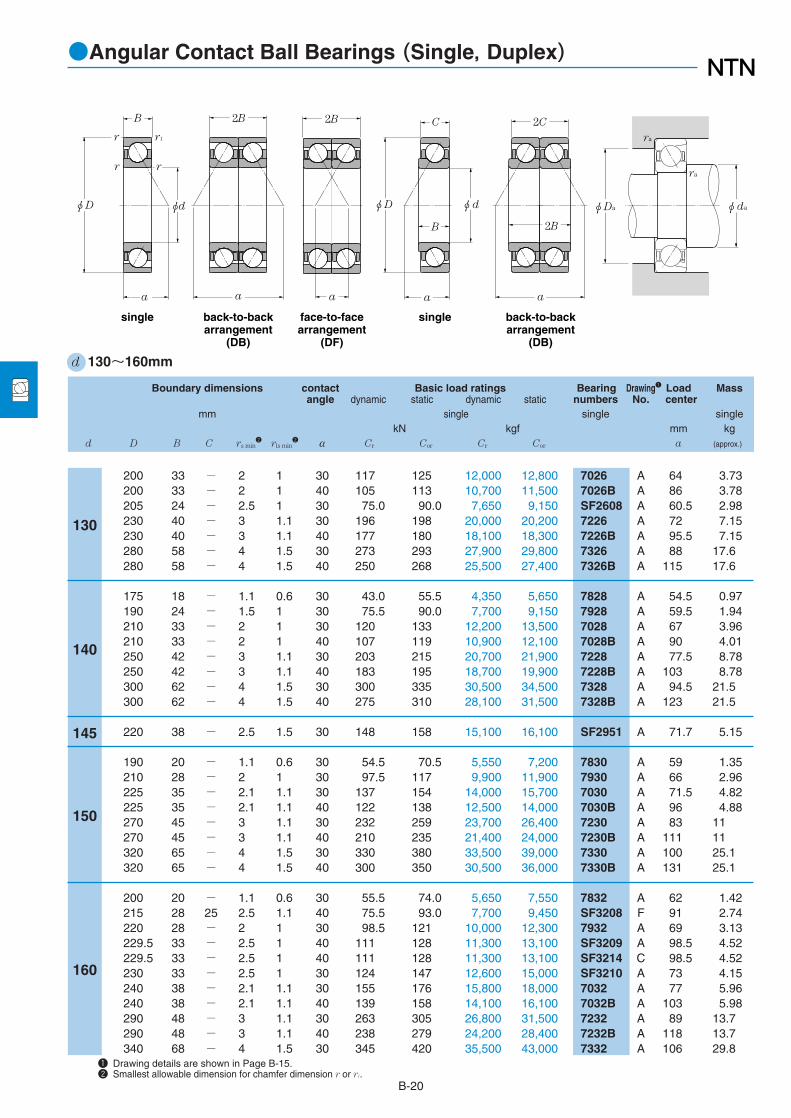
B-20
●Angular Contact Ball Bearings (Single, Duplex)
Boundary dimensions contact Basic load ratings Bearing Drawing1 Load Massangle dynamic static dynamic static numbers No. center
mm single single singlekN kgf mm kg
d D B C rs min2
rls min2 α Cr Cor Cr Cor a (approx.)
1 Drawing details are shown in Page B-15.2 Smallest allowable dimension for chamfer dimension r or r1.
d 130~160mm
200 33 - 2 1 30 117 125 12,000 12,800 7026 A 64 3.73200 33 - 2 1 40 105 113 10,700 11,500 7026B A 86 3.78205 24 - 2.5 1 30 75.0 90.0 7,650 9,150 SF2608 A 60.5 2.98230 40 - 3 1.1 30 196 198 20,000 20,200 7226 A 72 7.15230 40 - 3 1.1 40 177 180 18,100 18,300 7226B A 95.5 7.15280 58 - 4 1.5 30 273 293 27,900 29,800 7326 A 88 17.6280 58 - 4 1.5 40 250 268 25,500 27,400 7326B A 115 17.6
175 18 - 1.1 0.6 30 43.0 55.5 4,350 5,650 7828 A 54.5 0.97190 24 - 1.5 1 30 75.5 90.0 7,700 9,150 7928 A 59.5 1.94210 33 - 2 1 30 120 133 12,200 13,500 7028 A 67 3.96210 33 - 2 1 40 107 119 10,900 12,100 7028B A 90 4.01250 42 - 3 1.1 30 203 215 20,700 21,900 7228 A 77.5 8.78250 42 - 3 1.1 40 183 195 18,700 19,900 7228B A 103 8.78300 62 - 4 1.5 30 300 335 30,500 34,500 7328 A 94.5 21.5300 62 - 4 1.5 40 275 310 28,100 31,500 7328B A 123 21.5
220 38 - 2.5 1.5 30 148 158 15,100 16,100 SF2951 A 71.7 5.15
190 20 - 1.1 0.6 30 54.5 70.5 5,550 7,200 7830 A 59 1.35210 28 - 2 1 30 97.5 117 9,900 11,900 7930 A 66 2.96225 35 - 2.1 1.1 30 137 154 14,000 15,700 7030 A 71.5 4.82225 35 - 2.1 1.1 40 122 138 12,500 14,000 7030B A 96 4.88270 45 - 3 1.1 30 232 259 23,700 26,400 7230 A 83 11270 45 - 3 1.1 40 210 235 21,400 24,000 7230B A 111 11320 65 - 4 1.5 30 330 380 33,500 39,000 7330 A 100 25.1320 65 - 4 1.5 40 300 350 30,500 36,000 7330B A 131 25.1
200 20 - 1.1 0.6 30 55.5 74.0 5,650 7,550 7832 A 62 1.42215 28 25 2.5 1.1 40 75.5 93.0 7,700 9,450 SF3208 F 91 2.74220 28 - 2 1 30 98.5 121 10,000 12,300 7932 A 69 3.13229.5 33 - 2.5 1 40 111 128 11,300 13,100 SF3209 A 98.5 4.52229.5 33 - 2.5 1 40 111 128 11,300 13,100 SF3214 C 98.5 4.52230 33 - 2.5 1 30 124 147 12,600 15,000 SF3210 A 73 4.15240 38 - 2.1 1.1 30 155 176 15,800 18,000 7032 A 77 5.96240 38 - 2.1 1.1 40 139 158 14,100 16,100 7032B A 103 5.98290 48 - 3 1.1 30 263 305 26,800 31,500 7232 A 89 13.7290 48 - 3 1.1 40 238 279 24,200 28,400 7232B A 118 13.7340 68 - 4 1.5 30 345 420 35,500 43,000 7332 A 106 29.8
130
140
150
160
145
ra
ra
φdaφDa φD φd
B
r1
r
a
2B 2B
a a
r
r
single back-to-backarrangement
(DB)
face-to-facearrangement
(DF)
single back-to-backarrangement
(DB)
2C
2B
C
B
a
φD φd
a

B-21
Basic load ratings Bearing Load Abutment anddynamic static dynamic static numbers center fillet dimensions
(duplex) (duplex) mm mmKN kgf a da Da ras rlas
Cr Cor Cr Cor DB DF DB DF min max max max
●Angular Contact Ball Bearings (Single, Duplex)
191 251 19,400 25,600 DB DF 161 95 140 190 2 1171 226 17,400 23,100 DB DF 171.5 105.5 140 190 2 1122 180 12,500 18,300 DB DF 120.5 72.5 142 193 2 1320 395 32,500 40,500 DB DF 184 104 144 216 2.5 1288 360 29,400 36,500 DB DF 231 151 144 216 2.5 1445 585 45,500 59,500 DB DF 234 118 148 262 3 1.5405 535 41,500 54,500 DB DF 288 172 148 262 3 1.5
69.5 111 7,100 11,300 DB DF 109 73 147 168 1 0.6123 180 12,500 18,300 DB DF 143 95 148.5 181.5 1.5 1194 265 19,800 27,000 DB DF 167 101 150 200 2 1174 237 17,700 24,200 DB DF 180 114 150 200 2 1330 430 33,500 44,000 DB DF 197 113 154 236 2.5 1297 390 30,500 40,000 DB DF 248 164 154 236 2.5 1490 670 50,000 68,500 DB DF 251 127 158 282 3 1.5445 615 45,500 63,000 DB DF 308 184 158 282 3 1.5
241 315 24,500 32,000 DB DF 143.5 67.5 157 208 2 1.5
88.5 141 9,000 14,400 DB DF 118 78 157 183 1 0.6158 234 16,100 23,900 DB DF 160 104 160 200 2 1222 305 22,700 31,500 DB DF 178 108 162 213 2 1199 275 20,300 28,100 DB DF 192.5 122.5 162 213 2 1375 515 38,500 53,000 DB DF 211 121 164 256 2.5 1340 470 34,500 48,000 DB DF 267 177 164 256 2.5 1535 765 54,500 78,000 DB DF 265 135 168 302 3 1.5490 700 50,000 71,500 DB DF 327 197 168 302 3 1.5
90.5 148 9,200 15,100 DB DF 124 84 167 193 1 0.6123 186 12,500 18,900 DB - 182.5 132.5 172 203 2 1160 241 16,300 24,600 DB DF 166 110 170 210 2 1180 256 18,300 26,100 DB DF 196.5 130.5 172 217.5 2 1180 256 18,300 26,100 - DF 196.5 130.5 172 217.5 2 1201 293 20,500 29,900 DB DF 145.5 79.5 172 218 2 1252 355 25,700 36,000 DB DF 192 116 172 228 2 1225 315 23,000 32,500 DB DF 206 130 172 228 2 1425 615 43,500 62,500 DB DF 226 130 174 276 2.5 1385 555 39,500 57,000 DB DF 284 188 174 276 2.5 1565 845 57,500 86,000 DB DF 280 144 178 322 3 1.5
30˚
e
X Y
Fa / Fr≦e Fa / Fr>e
Single DB, DFFa / Fr≦e Fa / Fr>e
X Y X Y X Y
40˚0.801.14
11
00
0.390.35
0.760.57
11
0.780.55
0.630.57
1.240.93
For single, When Por<Fr use Por=Fr
30˚Xo
Single DB, DF
40˚0.50.5
Yo Xo Yo0.330.26
11
0.660.52
Pr=XFr+YFa
Equivalent bearing loaddynamic
Por=Xo Fr+Yo Fastatic
Con-tactangle
Con-tactangle
φDb φda
rara
φDaφda
rar1a

B-22
●Angular Contact Ball Bearings (Single, Duplex)
Boundary dimensions contact Basic load ratings Bearing Drawing1 Load Massangle dynamic static dynamic static numbers No. center
mm single single singlekN kgf mm kg
d D B C rs min2
rls min2 α Cr Cor Cr Cor a (approx.)
1 Drawing details are shown in Page B-15.2 Smallest allowable dimension for chamfer dimension r or r1.
d 160~195mm
340 68 - 4 1.5 40 315 385 32,000 39,500 7332B A 139 29.8
215 22 - 1.1 0.6 30 68.5 90.5 6,950 9,250 7834 A 66.5 1.88230 28 - 2 1 30 102 129 10,400 13,100 7934 A 71.5 3.29260 42 - 2.1 1.1 30 186 214 18,900 21,900 7034 A 83 7.96260 42 - 2.1 1.1 40 166 193 17,000 19,700 7034B A 111.5 8.02310 52 - 4 1.5 30 295 360 30,000 36,500 7234 A 95.5 17310 52 - 4 1.5 40 266 325 27,200 33,000 7234B A 127 17360 72 - 4 1.5 30 390 485 39,500 49,500 7334 A 113 35.3360 72 - 4 1.5 40 355 445 36,000 45,500 7334B A 147 35.3
225 22 - 1.1 0.6 30 70.0 95.0 7,100 9,700 7836 A 69.5 1.98250 33 - 2 1 30 131 163 13,400 16,600 7936 A 78.5 4.87259.5 33 - 2.5 1 40 138 166 14,100 16,900 SF3618 B 109 5.7259.5 33 - 2.5 1 30 178 211 18,200 21,500 SF3629 C 80 5.8259.5 33 - 2.5 1 30 178 211 18,200 21,500 SF3639 B 80 5.75259.5 33 - 2.5 1 30 155 190 15,800 19,400 SF3641 C 80 5.65280 46 - 2.1 1.1 30 219 266 22,300 27,100 7036 A 89.5 10.4280 46 - 2.1 1.1 40 196 240 20,000 24,400 7036B A 119.5 10.5320 52 - 4 1.5 30 305 385 31,000 39,000 7236 A 98 17.7320 52 - 4 1.5 40 276 350 28,100 35,500 7236B A 131 17.7380 75 - 4 1.5 30 410 535 41,500 54,500 7336 A 118 40.9380 75 - 4 1.5 40 375 490 38,000 50,000 7336B A 155 40.9
240 24 - 1.5 1 30 85.0 116 8,650 11,800 7838 A 74 2.55255 33 29 2.5 1.5 40 108 138 11,000 14,100 SF3806 F 108 4.16259.5 33 - 2 1 30 133 169 13,500 17,200 SF3816 C 81.5 5.1260 33 - 2 1 30 133 169 13,500 17,200 7938 A 81.5 5.1269.5 33 - 2.5 1.5 30 132 168 13,500 17,100 SF3802 A 83 5.95269.5 33 - 2.5 2.5 40 134 166 13,600 16,900 SF3807 B 113 6.05290 46 - 2.1 1.1 30 224 280 22,800 28,600 7038 A 92.5 10.8290 46 - 2.1 1.1 40 201 253 20,400 25,800 7038B A 124 10.9340 55 - 4 1.5 30 305 390 31,000 39,500 7238 A 104 21.3340 55 - 4 1.5 40 273 355 27,800 36,000 7238B A 139 21.3400 78 - 5 2 30 430 585 44,000 59,500 7338 A 124 47400 78 - 5 2 40 390 535 40,000 54,500 7338B A 163 47
270 35 - 2.5 1.5 30 153 196 15,600 20,000 SF3901 C 84.5 6.2
160
170
180
190
195
ra
ra
φdaφDa φD φd
B
r1
r
a
2B 2B
a a
r
r
single back-to-backarrangement
(DB)
face-to-facearrangement
(DF)
single back-to-backarrangement
(DB)
2C
2B
C
B
a
φD φd
a
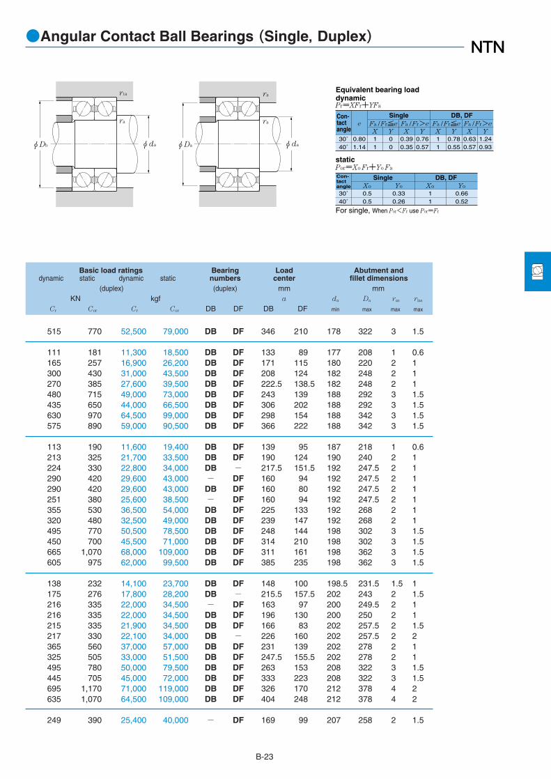
B-23
Basic load ratings Bearing Load Abutment anddynamic static dynamic static numbers center fillet dimensions
(duplex) (duplex) mm mmKN kgf a da Da ras rlas
Cr Cor Cr Cor DB DF DB DF min max max max
●Angular Contact Ball Bearings (Single, Duplex)
515 770 52,500 79,000 DB DF 346 210 178 322 3 1.5
111 181 11,300 18,500 DB DF 133 89 177 208 1 0.6165 257 16,900 26,200 DB DF 171 115 180 220 2 1300 430 31,000 43,500 DB DF 208 124 182 248 2 1270 385 27,600 39,500 DB DF 222.5 138.5 182 248 2 1480 715 49,000 73,000 DB DF 243 139 188 292 3 1.5435 650 44,000 66,500 DB DF 306 202 188 292 3 1.5630 970 64,500 99,000 DB DF 298 154 188 342 3 1.5575 890 59,000 90,500 DB DF 366 222 188 342 3 1.5
113 190 11,600 19,400 DB DF 139 95 187 218 1 0.6213 325 21,700 33,500 DB DF 190 124 190 240 2 1224 330 22,800 34,000 DB - 217.5 151.5 192 247.5 2 1290 420 29,600 43,000 - DF 160 94 192 247.5 2 1290 420 29,600 43,000 DB DF 160 80 192 247.5 2 1251 380 25,600 38,500 - DF 160 94 192 247.5 2 1355 530 36,500 54,000 DB DF 225 133 192 268 2 1320 480 32,500 49,000 DB DF 239 147 192 268 2 1495 770 50,500 78,500 DB DF 248 144 198 302 3 1.5450 700 45,500 71,000 DB DF 314 210 198 302 3 1.5665 1,070 68,000 109,000 DB DF 311 161 198 362 3 1.5605 975 62,000 99,500 DB DF 385 235 198 362 3 1.5
138 232 14,100 23,700 DB DF 148 100 198.5 231.5 1.5 1175 276 17,800 28,200 DB - 215.5 157.5 202 243 2 1.5216 335 22,000 34,500 - DF 163 97 200 249.5 2 1216 335 22,000 34,500 DB DF 196 130 200 250 2 1215 335 21,900 34,500 DB DF 166 83 202 257.5 2 1.5217 330 22,100 34,000 DB - 226 160 202 257.5 2 2365 560 37,000 57,000 DB DF 231 139 202 278 2 1325 505 33,000 51,500 DB DF 247.5 155.5 202 278 2 1495 780 50,000 79,500 DB DF 263 153 208 322 3 1.5445 705 45,000 72,000 DB DF 333 223 208 322 3 1.5695 1,170 71,000 119,000 DB DF 326 170 212 378 4 2635 1,070 64,500 109,000 DB DF 404 248 212 378 4 2
249 390 25,400 40,000 - DF 169 99 207 258 2 1.5
30˚
e
X Y
Fa / Fr≦e Fa / Fr>e
Single DB, DFFa / Fr≦e Fa / Fr>e
X Y X Y X Y
40˚0.801.14
11
00
0.390.35
0.760.57
11
0.780.55
0.630.57
1.240.93
For single, When Por<Fr use Por=Fr
30˚Xo
Single DB, DF
40˚0.50.5
Yo Xo Yo0.330.26
11
0.660.52
Pr=XFr+YFa
Equivalent bearing loaddynamic
Por=Xo Fr+Yo Fastatic
Con-tactangle
Con-tactangle
φDb φda
rara
φDaφda
rar1a

B-24
●Angular Contact Ball Bearings (Single, Duplex)
Boundary dimensions contact Basic load ratings Bearing Drawing1 Load Massangle dynamic static dynamic static numbers No. center
mm single single singlekN kgf mm kg
d D B C rs min2
rls min2 α Cr Cor Cr Cor a (approx.)
1 Drawing details are shown in Page B-15.2 Smallest allowable dimension for chamfer dimension r or r1.
d 200~250mm
250 24 - 1.5 1 30 87.0 122 8,850 12,400 7840 A 77 2.68279.5 38 - 2.5 1.5 40 165 202 16,800 20,600 SF4006 A 119.5 7.15280 38 - 2.1 1.1 30 185 231 18,900 23,600 7940 A 88.5 7.15289.5 38 - 2.5 1.5 40 188 238 19,200 24,200 SF4017 C 122 8.25310 51 - 2.1 1.1 30 252 325 25,700 33,000 7040 A 99 14310 51 - 2.1 1.1 40 226 293 23,000 29,900 7040B A 132.5 14.1360 58 - 4 1.5 30 335 450 34,500 46,000 7240 A 110 25.3360 58 - 4 1.5 40 305 410 31,000 41,500 7240B A 146 25.3420 80 - 5 2 30 450 605 46,000 62,000 7340 A 130 53.1420 80 - 5 2 40 410 555 42,000 56,500 7340B A 170 53.1
330.2 88.9 - 3 1.5 30 219 285 22,400 29,100 SF4104 A 99 14.7
270 24 - 1.5 1 30 89.0 131 9,100 13,300 7844 A 82.5 2.91300 38 - 2.1 1.1 30 187 239 19,000 24,300 7944 A 94 7.74300 38 35 2.5 1.5 40 149 189 15,200 19,300 SF4407 F 126.5 7.25309.5 38 - 2.1 1.1 40 190 246 19,400 25,100 SF4421 B 130 8.9309.5 38 - 2.1 1.1 40 190 246 19,400 25,100 SF4433 C 130 8.9319.5 46 - 2.1 1.1 35 226 299 23,000 30,500 SF4438 C 117.5 12.2340 56 - 3 1.1 30 286 390 29,100 39,500 7044 A 109 18.2340 56 - 3 1.1 40 238 325 24,300 33,000 7044B A 145.5 18.4400 65 - 4 1.5 30 345 485 35,000 49,500 7244 A 122 37.1460 88 - 5 2 30 495 725 50,500 74,000 7344 A 142 72.4
329.5 40 - 2.5 1.5 40 154 202 15,700 20,600 SF4614 E 135.5 11
300 28 - 2 1 30 101 155 10,300 15,800 7848 A 92 4.49320 38 - 2.1 1.1 30 193 255 19,600 26,000 7948 A 100 8.34329.5 40 - 2.1 1.1 30 221 305 22,600 31,000 SF4839 C 102.5 10329.5 40 - 2.5 1.5 40 197 265 20,100 27,000 SF4814 A 139.5 10.1329.5 40 - 2.5 1.5 40 197 265 20,100 27,000 SF4818 B 139.5 10.1340 40 - 2.5 1.5 30 211 289 21,500 29,400 SF4802 A 160.5 11.5360 56 - 3 1.1 30 279 400 28,500 40,500 7048 A 114.5 19.5360 56 - 3 1.1 40 249 355 25,400 36,000 7048B A 154 19.8440 72 - 4 1.5 30 420 630 42,500 64,500 7248 A 135.5 49.8500 95 - 5 2 30 515 795 52,500 81,000 7348 A 154.5 92.2
340 38 - 2.5 1 40 169 222 17,200 22,600 SF5005 F 141.5 9.55349.5 46 - 3 1.5 30 233 325 23,700 33,000 SF5004 A 109.5 13.6
200
203.2
230
240
250
220
ra
ra
φdaφDa φD φd
B
r1
r
a
2B 2B
a a
r
r
single back-to-backarrangement
(DB)
face-to-facearrangement
(DF)
single back-to-backarrangement
(DB)
2C
2B
C
B
a
φD φd
a

B-25
Basic load ratings Bearing Load Abutment anddynamic static dynamic static numbers center fillet dimensions
(duplex) (duplex) mm mmKN kgf a da Da ras rlas
Cr Cor Cr Cor DB DF DB DF min max max max
●Angular Contact Ball Bearings (Single, Duplex)
141 244 14,400 24,900 DB DF 154 106 208.5 241.5 1.5 1268 405 27,400 41,000 DB DF 239 163 212 267.5 2 1.5300 465 30,500 47,000 DB DF 215 139 212 268 2 1305 475 31,000 48,500 - DF 243.5 167.5 212 277.5 2 1.5410 650 41,500 66,000 DB DF 249 147 212 298 2 1365 585 37,500 60,000 DB DF 265 163 212 298 2 1550 900 56,000 92,000 DB DF 278 162 218 342 3 1.5495 815 50,500 83,000 DB DF 350 234 218 342 3 1.5730 1,210 74,500 124,000 DB DF 340 180 222 398 4 2665 1,110 68,000 113,000 DB DF 420 260 222 398 4 2
355 570 36,500 58,000 DB DF 198.5 109.5 217.2 316.2 2.5 1.5
145 261 14,800 26,600 DB DF 165.5 117.5 228.5 261.5 1.5 1305 475 31,000 48,500 DB DF 226 150 232 288 2 1243 380 24,700 38,500 DB - 253 183 232 288 2 1.5310 490 31,500 50,000 DB - 260.5 184.5 232 297.5 2 1310 490 31,500 50,000 - DF 260.5 184.5 232 297.5 2 1365 600 37,500 61,000 - DF 235 143 232 307.5 2 1465 780 47,500 79,500 DB DF 217.5 105.5 234 326 2.5 1385 650 39,500 66,000 DB DF 291 179 234 326 2.5 1560 975 57,000 99,000 DB DF 244 114 238 382 3 1.5805 1,450 82,000 148,000 DB DF 284.5 108.5 242 438 4 2
251 405 25,600 41,000 DB - 270.8 191 242 317.5 2 1.5
164 310 16,800 31,500 DB DF 184 128 250 290 2 1315 510 32,000 52,000 DB DF 238 162 252 308 2 1360 605 36,500 62,000 - DF 204.5 124.5 252 317.5 2 1320 530 32,500 54,000 DB DF 279 199 252 317.5 2 1.5320 530 32,500 54,000 DB - 279 199 252 317.5 2 1.5345 575 35,000 59,000 DB DF 207.5 127.5 252 328 2 1.5455 795 46,000 81,000 DB DF 229.5 117.5 254 346 2.5 1405 710 41,500 72,500 DB DF 308 196 254 346 2.5 1680 1,260 69,000 129,000 DB DF 271 127 258 422 3 1.5840 1,590 85,500 162,000 DB DF 309 119 262 478 4 2
275 445 28,000 45,500 DB - 282.5 212.5 262 328 2 1380 650 38,500 66,000 DB DF 219 127 264 335.5 2.5 1.5
30˚
e
X Y
Fa / Fr≦e Fa / Fr>e
Single DB, DFFa / Fr≦e Fa / Fr>e
X Y X Y X Y
40˚0.801.14
11
00
0.390.35
0.760.57
11
0.780.55
0.630.57
1.240.93
For single, When Por<Fr use Por=Fr
30˚Xo
Single DB, DF
40˚0.50.5
Yo Xo Yo0.330.26
11
0.660.52
Pr=XFr+YFa
Equivalent bearing loaddynamic
Por=Xo Fr+Yo Fastatic
Con-tactangle
Con-tactangle
φDb φda
rara
φDaφda
rar1a

B-26
●Angular Contact Ball Bearings (Single, Duplex)
Boundary dimensions contact Basic load ratings Bearing Drawing1 Load Massangle dynamic static dynamic static numbers No. center
mm single single singlekN kgf mm kg
d D B C rs min2
rls min2 α Cr Cor Cr Cor a (approx.)
1 Drawing details are shown in Page B-15.2 Smallest allowable dimension for chamfer dimension r or r1.
d 260~340mm
320 28 - 2 1 30 127 192 12,900 19,600 7852 A 97.5 4.83360 46 - 2.1 1.1 30 258 375 26,300 38,000 7952 A 112 14369.5 46 - 2.5 1.5 40 235 340 23,900 34,500 SF5206 C 155 16.1369.5 46 - 2.5 1.5 40 235 340 23,900 34,500 SF5225 B 155 15.7369.5 46 - 2.5 1.5 40 235 340 23,900 34,500 SF5224 A 155 15.7369.5 46 - 2.5 1.5 30 242 350 24,700 35,500 SF5210 D 114 15.7379.5 56 - 4 2 40 264 385 26,900 39,500 SF5218 A 162.5 19.1400 65 - 4 1.5 30 315 455 32,000 46,500 7052 A 128 28.7400 65 - 4 1.5 40 282 410 28,700 41,500 7052B A 171 29480 80 - 5 2 30 480 750 48,500 76,500 7252 A 147 66540 102 - 6 3 30 590 960 60,000 98,000 7352 A 166.5 115
350 33 - 2 1 30 164 247 16,700 25,200 7856 A 107.5 7.17380 46 - 2.1 1.1 30 261 385 26,600 39,500 7956 A 118 14.8389.5 46 - 2.1 1.1 40 223 325 22,700 33,000 SF5606 A 163.5 16389.5 46 - 2.5 1.5 30 250 370 25,500 38,000 SF5608 D 119.5 16420 65 - 4 1.5 30 390 595 40,000 60,500 7056 A 133.5 30.7420 65 - 4 1.5 40 350 540 35,500 55,000 7056B A 179.5 30.9500 80 - 5 2 30 535 860 54,500 87,500 7256 A 152.5 69.7580 108 - 6 3 30 670 1,140 68,000 116,000 7356 A 178 140
380 46 - 2.5 2 40 206 305 21,000 31,000 SF5702 A 162.5 14.7
419.5 60 - 5 2.5 40 292 455 29,800 46,500 SF5803 B 179 26.9
380 38 - 2.1 1.1 30 193 290 19,700 29,500 7860 A 117 10.1420 56 - 3 1.1 30 325 520 33,500 53,000 7960 A 132 23.7460 74 - 4 1.5 30 440 715 45,000 73,000 7060 A 146.5 43.4460 74 - 4 1.5 40 395 645 40,500 66,000 7060B A 196.5 43.7540 85 - 5 2 30 550 930 56,500 94,500 7260 A 164 87.2
429.5 60 - 4 2 40 297 470 30,500 48,000 SF6203 A 185.5 26.7
400 38 - 2.1 1.1 30 197 305 20,100 31,000 7864 A 123 10.7440 56 - 3 1.1 30 330 540 34,000 55,000 7964 A 137.5 24.7480 74 - 4 1.5 30 450 760 46,000 77,500 7064 A 152.5 45.7580 92 - 5 2 30 635 1,120 64,500 114,000 7264 A 176 109
420 38 - 2.1 1.1 30 204 325 20,800 33,500 7868 A 128.5 11.3
260
280
300
310
320
340
285
290
ra
φdaφDa
single back-to-backarrangement
(DB)
face-to-facearrangement
(DF)
φD
r1
r
a
φd
B
r
r
ra
2B
a
2B
a

B-27
Basic load ratings Bearing Load Abutment anddynamic static dynamic static numbers center fillet dimensions
(duplex) (duplex) mm mmKN kgf a da Da ras rlas
Cr Cor Cr Cor DB DF DB DF min max max max
●Angular Contact Ball Bearings (Single, Duplex)
206 385 21,000 39,000 DB DF 195.5 139.5 270 310 2 1420 750 42,500 76,500 DB DF 270 178 272 348 2 1380 680 39,000 69,000 - DF 310.5 218.5 272 357.5 2 1.5380 680 39,000 69,000 DB - 310.5 218.5 272 357.5 2 1.5380 680 39,000 69,000 DB DF 310.5 218.5 272 357.5 2 1.5395 695 40,000 71,000 DB DF 228 136 272 357.5 2 1.5430 775 44,000 79,000 DB DF 324.5 212.5 278 361.5 3 2510 905 52,000 92,500 DB DF 255.5 125.5 278 382 3 1.5458 820 46,500 83,500 DB DF 342 212 278 382 3 1.5775 1,500 79,000 153,000 DB DF 294 134 282 458 4 2960 1,920 98,000 196,000 DB DF 333 129 288 512 5 2.5
267 495 27,200 50,500 DB DF 215 148 290 340 2 1425 775 43,000 79,000 DB DF 282 190 292 368 2 1360 650 37,000 66,500 DB DF 327 235 292 377.5 2 1405 745 41,500 76,000 DB DF 239.5 147.5 292 377.5 2 1.5635 1,190 64,500 121,000 DB DF 267 137 298 402 3 1.5570 1,080 58,000 110,000 DB DF 359 229 298 402 3 1.5870 1,720 88,500 175,000 DB DF 305 145 258 478 4 2
1,080 2,270 111,000 232,000 DB DF 356.5 140.5 308 552 5 2.5
335 605 34,000 62,000 DB DF 325 233 297 368 2 2
475 910 48,500 93,000 DB - 357.5 237.5 312 397.5 4 2
315 580 32,000 59,000 DB DF 234.5 158.5 312 368 2 1530 1,040 54,000 106,000 DB DF 320 208 314 406 2.5 1715 1,430 73,000 146,000 DB DF 293.5 145.5 318 442 3 1.5640 1,290 65,500 132,000 DB DF 393 245 318 442 3 1.5895 1,860 91,500 189,000 DB DF 327.5 157.5 322 518 4 2
480 945 49,000 96,000 DB - 370.5 250.5 328 411.5 3 2
320 610 32,500 62,000 DB DF 246 170 332 388 2 1540 1,080 55,000 110,000 DB DF 275.5 163.5 334 426 2.5 1735 1,520 75,000 155,000 DB DF 305 152.5 338 462 3 1.5
1,030 2,230 105,000 228,000 DB DF 352 168 342 558 4 2
330 650 34,000 66,500 DB DF 257.5 181.5 352 408 2 1
30˚
e
X Y
Fa / Fr≦e Fa / Fr>e
Single DB, DFFa / Fr≦e Fa / Fr>e
X Y X Y X Y
40˚0.801.14
11
00
0.390.35
0.760.57
11
0.780.55
0.630.57
1.240.93
For single, When Por<Fr use Por=Fr
30˚Xo
Single DB, DF
40˚0.50.5
Yo Xo Yo0.330.26
11
0.660.52
Pr=XFr+YFa
Equivalent bearing loaddynamic
Por=Xo Fr+Yo Fastatic
Con-tactangle
Con-tactangle
φDb φda
rara
φDaφda
rar1a

B-28
●Angular Contact Ball Bearings (Single, Duplex)
Boundary dimensions contact Basic load ratings Bearing Drawing1 Load Massangle dynamic static dynamic static numbers No. center
mm single single singlekN kgf mm kg
d D B C rs min2
rls min2 α Cr Cor Cr Cor a (approx.)
1 Drawing details are shown in Page B-15.2 Smallest allowable dimension for chamfer dimension r or r1.
d 340~480mm
460 56 - 3 1.1 30 345 575 35,000 59,000 7968 A 143.5 26.0479.5 65 - 4 2 30 395 680 40,500 69,500 SF6807 A 151 36.7520 82 - 5 2 30 520 905 53,000 92,500 7068 A 165 61.1620 92 - 5 2 30 650 1,200 66,500 122,000 7268 A 184.5 127
440 38 - 2.1 1.1 30 226 365 23,100 37,000 7872 A 134.5 11.9480 56 - 3 1.1 30 350 595 35,500 60,500 7972 A 149.5 27.3509.5 70 - 5 2 40 390 685 40,000 69,500 SF7203 A 217.5 45540 82 - 5 2 30 530 960 54,500 98,000 7072 A 171 63.4650 95 - 6 3 30 670 1,280 68,500 130,000 7272 A 193.5 143
480 46 - 2.1 1.1 30 281 475 28,700 48,500 7876 A 147 19.5519.5 65 - 4 2 40 345 610 35,500 62,500 SF7603 A 221.5 41.3520 65 - 4 1.5 30 390 700 40,000 71,000 7976 A 162.5 39.6540 164 - 4 2 40 440 810 45,000 83,000 SF7601 A 234 61560 82 - 5 2 30 545 1,010 55,500 103,000 7076 A 176.5 66.3
500 46 - 2.1 1.1 30 287 500 29,300 51,000 7880 A 153 20.4540 65 - 4 1.5 30 395 720 40,000 73,500 7980 A 168 41600 90 - 5 2 30 615 1,180 63,000 121,000 7080 A 189.5 86.1
520 46 - 2.1 1.1 30 310 555 31,500 56,500 7884 A 158.5 21.1560 65 - 4 1.5 30 410 765 41,500 78,000 7984 A 174 42.8620 90 - 5 2 30 630 1,250 64,500 127,000 7084 A 195 89.7
540 46 - 2.1 1.1 30 310 565 31,500 58,000 7888 A 164.5 22600 74 - 4 1.5 30 445 860 45,500 87,500 7988 A 187 59.3650 94 - 6 3 30 645 1,310 65,500 134,000 7088 A 204.5 103
540 40 - 2.1 1.1 30 249 455 25,400 46,000 SF9211 A 164.5 15.8580 56 - 3 1.1 30 380 725 39,000 74,000 7892 A 178 33.5620 74 - 4 1.5 30 450 885 46,000 90,000 7992 A 193 61.6680 100 - 6 3 30 720 1,510 73,500 154,000 7092 A 214.5 119
570 50 - 2.1 1.1 30 320 605 32,500 62,000 SF9404 A 175 25.7
600 56 - 3 1.1 30 390 760 40,000 77,500 7896 A 184 34.9650 78 - 5 2 30 530 1,090 54,000 111,000 7996 A 202 71.8700 100 - 6 3 30 715 1,520 73,000 155,000 7096 A 220.5 123
340
360
380
420
440
460
470
480
400
ra
φdaφDa
single back-to-backarrangement
(DB)
face-to-facearrangement
(DF)
φD
r1
r
a
φd
B
r
r
ra
2B
a
2B
a

B-29
Basic load ratings Bearing Load Abutment anddynamic static dynamic static numbers center fillet dimensions
(duplex) (duplex) mm mmKN kgf a da Da ras rlas
Cr Cor Cr Cor DB DF DB DF min max max max
●Angular Contact Ball Bearings (Single, Duplex)
560 1,150 57,000 118,000 DB DF 287 175 354 446 2.5 1645 1,360 65,500 139,000 - DF 301.5 171.5 358 461.5 3 2845 1,810 86,000 185,000 DB DF 330.5 166.5 362 498 4 2
1,060 2,400 108,000 244,000 DB DF 369 185 362 598 4 2
370 725 37,500 74,000 DB DF 269 193 372 428 2 1565 1,190 57,500 121,000 DB DF 298.5 186.5 374 466 2.5 1635 1,370 64,500 140,000 DB - 435 295 382 487.5 4 2865 1,920 88,000 196,000 DB DF 342 178 382 518 4 2
1,090 2,550 111,000 260,000 DB DF 386.5 196.5 388 622 5 2.5
455 955 46,500 97,500 DB DF 294.5 202.5 392 468 2 1565 1,220 57,500 125,000 DB - 442.5 312.5 398 501.5 3 2635 1,400 64,500 142,000 DB DF 325 195 398 502 3 1.5715 1,620 73,000 166,000 - DF 468 304 398 522 3 2865 1,920 88,000 196,000 DB DF 342 178 402 538 4 2
465 1,000 47,500 102,000 DB DF 306 214 412 488 2 1640 1,440 65,500 147,000 DB DF 336.5 206.5 418 522 3 1.5
1,000 2,370 102,000 241,000 DB DF 379 199 422 578 4 2
505 1,110 51,500 113,000 DB DF 317.5 225.5 432 508 2 1660 1,530 67,500 156,000 DB DF 348 218 438 542 3 1.5
1,030 2,500 105,000 255,000 DB DF 390.5 210.5 442 598 4 2
505 1,130 51,500 116,000 DB DF 329 237 452 528 2 1720 1,720 73,500 175,000 DB DF 374.5 226.5 458 582 3 1.5
1,050 2,630 107,000 268,000 DB DF 409 221 468 622 5 2.5
405 905 41,500 92,500 DB - 328.5 248.5 472 528 2 1620 1,450 63,000 148,000 DB DF 356.5 244.5 474 566 2.5 1730 1,770 74,500 180,000 DB DF 386 238 478 602 3 1.5117 300 12,000 31,000 DB DF 429 229 488 652 5 2.5
520 1,210 53,000 124,000 DB - 350 250 482 558 2 1
635 1,520 64,500 155,000 DB DF 368 256 494 586 2.5 1860 2,180 88,000 223,000 DB DF 404.5 248.5 502 628 4 2
1,170 3,050 119,000 310,000 DB DF 441 241 508 672 5 2.5
30˚
e
X Y
Fa / Fr≦e Fa / Fr>e
Single DB, DFFa / Fr≦e Fa / Fr>e
X Y X Y X Y
40˚0.801.14
11
00
0.390.35
0.760.57
11
0.780.55
0.630.57
1.240.93
For single, When Por<Fr use Por=Fr
30˚Xo
Single DB, DF
40˚0.50.5
Yo Xo Yo0.330.26
11
0.660.52
Pr=XFr+YFa
Equivalent bearing loaddynamic
Por=Xo Fr+Yo Fastatic
Con-tactangle
Con-tactangle
φDb φda
rara
φDaφda
rar1a

B-30
●Angular Contact Ball Bearings (Single, Duplex)
Boundary dimensions contact Basic load ratings Bearing Drawing1 Load Massangle dynamic static dynamic static numbers No. center
mm single single singlekN kgf mm kg
d D B C rs min2
rls min2 α Cr Cor Cr Cor a (approx.)
1 Drawing details are shown in Page B-15.2 Smallest allowable dimension for chamfer dimension r or r1.
d 500~1,060mm
620 56 - 3 1.1 30 395 780 40,000 79,500 78/500 A 189.5 36.5670 78 - 5 2 30 540 1,120 55,000 115,000 79/500 A 208 74.9720 100 - 6 3 30 735 1,590 75,000 163,000 70/500 A 226 129
700 100 - 5 2.5 30 670 1,450 68,000 147,000 SF10013 A 223 87.3750 85 - 5 2 30 620 1,380 63,500 141,000 79/560 A 231.5 105
780 69 - 4 1.5 30 500 1,140 51,000 116,000 78/630A A 238 72.2
820 69 - 4 1.5 30 475 1,080 48,000 110,000 78/670 A 249.5 76.3820 69 - 4 1.5 40 420 945 43,000 96,500 78/670B A 347 76.3
900 74 - 4 1.5 30 530 1,290 54,000 131,000 SF14001 A 268 117
1,420 130 - 7.5 4 30 1,440 4,650 147,000 470,000 SF20001 A 414.5 654
1,280 100 - 6 3 30 880 2,680 895,000 273,000 78/1060 A 387.5 255
500
560
630
670
700
1,000
1,060
ra
φdaφDa
single back-to-backarrangement
(DB)
face-to-facearrangement
(DF)
φD
r1
r
a
φd
B
r
r
ra
2B
a
2B
a

B-31
Basic load ratings Bearing Load Abutment anddynamic static dynamic static numbers center fillet dimensions
(duplex) (duplex) mm mmKN kgf a da Da ras rlas
Cr Cor Cr Cor DB DF DB DF min max max max
●Angular Contact Ball Bearings (Single, Duplex)
640 1,560 65,000 159,000 DB DF 379.5 267.5 514 606 2.5 1875 2,250 89,000 229,000 DB DF 416 260 522 648 4 2
1,190 3,200 122,000 325,000 DB DF 452.5 252.5 528 692 5 2.5
1,080 2,890 111,000 295,000 DB DF 446.5 246.5 522 678 4 21,010 2,760 103,000 281,000 DB DF 463.5 293.5 582 728 4 2
815 2,270 83,000 232,000 DB DF 476 338 648 762 3 1.5
770 2,150 78,500 219,000 DB DF 499 361 688 802 3 1.5680 1,890 69,500 193,000 DB DF 694 556 688 802 3 1.5
860 2,580 88,000 263,000 DB DF 536 388 718 882 3 1.5
2,340 9,250 238,000 945,000 DB DF 828.5 568.5 1,036 1,384 6 3
1,430 5,350 146,000 545,000 DB DF 775.5 575.5 1,088 1,252 5 2.5
30˚
e
X Y
Fa / Fr≦e Fa / Fr>e
Single DB, DFFa / Fr≦e Fa / Fr>e
X Y X Y X Y
40˚0.801.14
11
00
0.390.35
0.760.57
11
0.780.55
0.630.57
1.240.93
For single, When Por<Fr use Por=Fr
30˚Xo
Single DB, DF
40˚0.50.5
Yo Xo Yo0.330.26
11
0.660.52
Pr=XFr+YFa
Equivalent bearing loaddynamic
Por=Xo Fr+Yo Fastatic
Con-tactangle
Con-tactangle
φDb φda
rara
φDaφda
rar1a

B-32
●Double Row Angular Contact Ball Bearings
Boundary dimensions Contact Basic load ratings Bearing Drawing1
angle dynamic static dynamic static numbers No.mm kN kgf
d D BorBl CorCl rs min2
rls min2 α Cr Cor Cr Cor
1 Drawing details are shown in Page B-16.2 Smallest allowable dimension for chamfer dimension r or r1.
d 100~190mm
B1
C
a
φD φd
r1
r
C1
a
φD φd
r
r
B
C
B1
φD φd
r1
r
a
170 60.3 60.3 2.5 2.5 40 160 179 16,300 18,200 DE2010 D
169.5 56 56 2.5 - 30 149 186 15,200 18,900 DE2208 B
190 66 66 2.5 1 30 187 236 19,000 24,100 DE2405 F190 66 66 2.5 1 30 187 236 19,000 24,100 DE2409 D
200 66 66 2.5 - 30 191 251 19,400 25,600 DE2601 B
210 66 66 2 - 40 203 266 20,700 27,100 DE2812 A210 66 66 1 - 40 179 248 18,300 25,300 DE2806 B210 66 66 2.5 - 30 194 265 19,800 27,000 DE2807 B
225 70 70 2.5 - 30 222 305 22,700 31,500 DE3010 A225 70 70 2.5 - 30 222 305 22,700 31,500 DE3011 B225 73 73 2.5 - 30 216 293 22,000 29,900 DE3009 A230 70 70 2.5 1.5 30 222 305 22,700 31,500 DE3007 F230 70 70 2 2 40 198 275 20,200 28,100 DE3019 D
215 56 50 2 1.1 40 123 186 12,500 18,900 DE3207 C240 76 76 2.5 - 30 252 355 25,700 36,000 DE3201 A
260 84 84 2.5 - 30 300 430 31,000 43,500 DE3402 A
280 92 92 2.5 - 40 320 480 32,500 49,000 DE3502 A280 92 92 2.5 - 40 320 480 32,500 49,000 DE3501 A
250 66 66 2.5 - 40 185 275 18,900 28,000 DE3606 A250 70 70 2.5 1 40 190 285 19,300 29,100 DE3609 F259.5 66 66 2.5 1 30 212 325 21,600 33,000 DE3610 D259.5 66 66 2.5 1 30 212 325 21,600 33,000 DE3601 F259.5 66 66 2.5 - 40 224 330 22,800 34,000 DE3608 B259.5 66 66 2 - 40 224 330 22,800 34,000 DE3615 A259.5 66 66 2.5 - 30 251 380 25,600 38,500 DE3603 A259.5 66 66 2.5 2.5 30 212 325 21,600 33,000 DE3612 D280 92 92 2.5 - 30 345 505 35,000 51,500 DE3605 A
269.5 66 66 2.5 1 30 215 335 21,900 34,500 DE3807 D269.5 66 66 2.5 1 30 215 335 21,900 34,500 DE3801 F
190
180
175
160
170
150
130
100
140
110
120

B-33
Abutment and Load Massfillet dimensions center
mm mmda Da ras rlas kgmin max max max a (approx.)
●Double Row Angular Contact Ball Bearings
φDa φDaφda φda
ra
ra
r1a
ra
158 112 2 2 143 5.64
157.5 112 2 - 54.5 4.61
184.5 132 2 1 122 7.09184.5 132 2 1 122 7.09
188 142 2 - 64 7.54
198 150 2 - 90 8204.5 152 2 - 90 7.76198 152 2 - 67 7.72
213 162 2 - 71.5 9.74213 162 2 - 71.5 9.74213 162 2 - 72.5 9.69221.5 162 2 1.5 143 9.74221.5 158.5 2 2 194 9.74
208 170 2 1 182 5.71228 172 2 - 76.5 12
248 182 2 - 111 16.1
268 187 2 - 119 21.7268 187 2 - 88.5 21.7
238 192 2 - 106 9.83244.5 192 2 1 215 10.4254 192 2 1 160 10.4254 192 2 1 160 10.4247.5 192 2 - 109 10.7249.5 190 2 - 109 10.7247.5 192 2 - 80 10.7247.5 192 2 2 160 10.4268 192 2 - 89.5 20.9
264 202 2 1 166 11.9264 202 2 1 166 11.9
30˚
e
X Y
Fa / Fr≦e Fa / Fr>e
Single DB, DFFa / Fr≦e Fa / Fr>e
X Y X Y X Y
40˚0.801.14
11
00
0.390.35
0.760.57
11
0.780.55
0.630.57
1.240.93
For single, When Por<Fr use Por=Fr
30˚Xo
Single DB, DF
40˚0.50.5
Yo Xo Yo0.330.26
11
0.660.52
Pr=XFr+YFa
Equivalent bearing loaddynamic
Con-tactangle
Por=Xo Fr+Yo Fastatic
Con-tactangle

B-34
●Double Row Angular Contact Ball Bearings
Boundary dimensions Contact Basic load ratings Bearing Drawing1
angle dynamic static dynamic static numbers No.mm kN kgf
d D BorBl CorCl rs min2
rls min2 α Cr Cor Cr Cor
1 Drawing details are shown in Page B-16.2 Smallest allowable dimension for chamfer dimension r or r1.
d 200~360mm
B1
C
a
φD φd
r1
r
C1
a
φD φd
r
r
B
C
B1
φD φd
r1
r
a
279.5 76 76 2.5 1.5 30 253 405 25,800 41,500 DE4004 F279.5 76 76 2.5 - 30 253 405 25,800 41,500 DE4008 B289.5 76 76 2.5 1.5 40 260 385 26,500 39,500 DE4010 G289.5 76 76 2.5 2.1 30 269 420 27,500 42,500 DE4019 D289.5 76 76 2.5 1.5 30 269 420 27,500 42,500 DE4009 F289.5 76 76 2.5 1.5 30 269 420 27,500 42,500 DE4002 F289.5 76 76 2.5 1.5 30 269 420 27,500 42,500 DE4012 D310 102 102 2.5 - 30 410 650 41,500 66,000 DE4007 A
309.5 76 76 2.5 - 30 325 520 33,000 53,000 DE4403 A309.5 76 76 2.5 - 30 325 520 33,000 53,000 DE4404 A309.5 76 76 2.1 1.1 30 325 520 33,000 53,000 DE4408 D319.5 92 92 2.5 - 30 375 625 38,500 63,500 DE4409 A319.5 92 92 2.5 - 40 335 550 34,500 56,000 DE4406 A
329.5 80 80 2.5 1.5 30 350 585 36,000 59,500 DE4602 F329.5 80 80 2.5 1.5 30 350 585 36,000 59,500 DE4603 D329.5 80 80 2.5 1.5 30 350 585 36,000 59,500 DE4605 E
359.5 112 112 3 1.5 40 440 770 45,000 78,500 DE4803 F
340 76 70 2 2 30 272 480 27,800 49,000 DE5004 C
369.5 92 92 2.5 - 40 380 680 39,000 69,000 DE5213 A369.5 92 92 2.5 - 30 430 775 43,500 79,000 DE5211 A369.5 92 92 2.5 2.5 30 395 695 40,000 71,000 DE5212 F
389.5 92 92 2.1 1.1 30 405 745 41,500 76,000 DE5605 D
429.5 112 112 3 - 30 530 1,040 54,000 106,000 DE6001 A
540 164 164 5 - 30 725 1,630 74,000 166,000 DE7201 A360
300
240
250
260
280
230
220
200

B-35
Abutment and Load Massfillet dimensions center
mm mmda Da ras rlas kgmin max max max a (approx.)
●Double Row Angular Contact Ball Bearings
φDa φDaφda φda
ra
ra
r1a
ra
271 212 2 1.5 177 14.3267.5 212 2 - 88.5 14.3281 212 2 1.5 244 16.5277.5 212 2 2 179 16.4281 212 2 1.5 180 16.4281 212 2 1.5 179 16.4281 212 2 1.5 179 16.4298 212 2 - 99 28.3
297.5 232 2 - 95.5 17.8297.5 232 2 - 95.5 17.8302.5 232 2 1 191 17.8307.5 232 2 - 101 24.4307.5 232 2 - 136 24.4
321 242 2 1.5 202 22321 242 2 1.5 202 22321 242 2 1.5 202 22
351 254 2.5 1.5 308 39.7
328 262 2 2 208 18.4
357.5 272 2 - 155 31.3357.5 272 2 - 114 31.3357.5 272 2 2 228 30.9
382.5 292 2 1 239 33.4
417.5 312 2.5 - 132 52.4
518 382 4 - 171 131
30˚
e
X Y
Fa / Fr≦e Fa / Fr>e
Single DB, DFFa / Fr≦e Fa / Fr>e
X Y X Y X Y
40˚0.801.14
11
00
0.390.35
0.760.57
11
0.780.55
0.630.57
1.240.93
For single, When Por<Fr use Por=Fr
30˚Xo
Single DB, DF
40˚0.50.5
Yo Xo Yo0.330.26
11
0.660.52
Pr=XFr+YFa
Equivalent bearing loaddynamic
Con-tactangle
Por=Xo Fr+Yo Fastatic
Con-tactangle

Cylindrical Roller Bearings

●Cylindrical Roller Bearings
1. Structure and Characteristics
Since the rollers of the cylindrical roller bearings make linecontact with the raceways, these bearings can support heavyradial loads and are suitable for high speed operation.
Assembly and disassembly are comparatively easy even ifthe inner or outer ring requires a shrink fit, as the bearing is aseparation type.
B-37
Model code Drawing Characteristics
¡Model NU has ribs on the outer ring and the inner ring can be separated from "the arranged set of outer ring, rollers and cage". Model N has ribs on the inner ring and the
outer ring can be separated from "the arranged set of inner ring, rollers and cage".
¡This bearing cannot support axial loads.
¡The most suitable model widely used as the free end bearing.
¡Model NJ has ribs on the outer ring and a rib on the inner ring.
Model NF has a rib on the outer ring and ribs on the inner ring.
¡These bearings support axial loads in one direction only.
¡There may be a case to use two bearings adjacent when they are used regardless of the
fixed end or free end.
¡Model NUP has a rib ring added on the side of the inner ring where it did not have a rib.
Model NJ with the added ring rib of Model L is Model NH. The inner ring should be fixed
along the axial direction since each ring rib will be separated.
¡These bearings support axial loads in either direction.
¡There may be a case to use as the fixed end bearing.
Model NU
Model N
Model NJ
Model NF
Model NUP
Model NH(NJ+HJ)
Model NUP
Model NF
Model NJ
Model N
Model NU
Model NH
Table 1 Model and characteristics of the single row cylindrical roller bearings
Model code Drawing Characteristics
¡These bearings are used in the main shaft of machine tools, rolling mill rolls and printing
machine plate cylinders where thin walled bearings are needed.
¡To use the bearing in the main shaft of machine tools, adjust the radial internal clearance
by inserting a tapered inner ring to the tapered shaft.
Model NNU
Model NN
Model NNU
Cylindrical hole Tapered hole
Model NNCylindrical hole Tapered hole
Table 2 Model and characteristics of the double row cylindrical roller bearings
Cylindrical roller bearings are classified as single row,double row and four row type, according to how many rollersare used, and there are models as shown in Table 1 to 3.
Although designed as a thin wall type, the SL Modeldouble row cylindrical roller bearing can support enormousradial and impact loads. Table 4 lists the configurationsavailable.
Note: Model E provides higher load capacity designed with increased diameter,length and numbers of rollers but the boundary dimensions are same as thestandard type bearings.

●Cylindrical Roller Bearings
B-38
Drawing Characteristics
Refer to the drawings.
Drawing numbers arelisted in the dimensions table.
¡ The bearing is mainly used for the roll neck of a rolling mill, and is designed so as to handle the maximum rating load for the allowable space in the roll neck part. Carbonized steel may be used to provide better resistance to cracking or impact to the inner ring.
¡ Consult NTN Engineering about the fitting and bearing internal clearance when the bearing is used for the preparing roll of a rolling mill.
¡ NTN provides bearings with special configurations: with tapered shaft holes; for high speed use; designed to prevent creeping; and, with dust and waterproof seals.
Table 3 Models and characters of four row cylindrical roller bearings
A B C
E F G
D
Drawings
Table 4 Model and Characteristics of the Model SL cylindrical roller bearings
Model Characteristics
Model SL01
Model SL02
¡Fixed end is Model SL01, free end is Model SL02.
¡Since the outer ring is split in the circumference direction using a special method and fixed as a unit
after mounting rollers, the bearing side face should be securely fixed using the shaft or
housing shoulder in the axial direction.
¡Outer ring has an oil groove and port.
¡Model SL01 can support axial loads from both directions via rollers.
¡Shoulder dimensions of shaft and bearings generally applies Da and da dimensions in the dimensions
table, but J and K dimensions are used when the moment or large axial loads are applied.
¡Model SL04 only with the fixed side.
¡Since the inner ring is split in the circumference direction using a special method and fixed as a unit
after mounting rollers, the bearing side face should be securely fixed by using the shaft or housing
shoulder in the axial direction.
¡Inner ring has an oil groove and port.
¡Model SL04 can support radial and axial loads in either directions.
¡A sealed bearing prelubricated with grease, the outer ring is fitted with a locating snap ring, making it
easy to handle and appropriate for sheaves and other applications.
¡Surface coating is added for rust prevention.
Model SL04
Note: We also provide 3-row, 4-row and 5-row bearings for the Model SL cylindrical roller bearing. Consult NTN Engineering for further details.
Op
en t
ype
En
clo
sed
typ
e
RemarksDrawings from A to E show the long cylindrical rollers andthe machined cage. Drawings from F to G show the hollowrollers and the pin type cage.
Suffix to the drawing numberM: Bearings which outer ring lubrication port is equipped
with a fitting nozzle for oil mist.R: Inner ring has a helical groove on its inner surface.S: Special specifications.
Note 1) The bearing has lubricant grooves on both sides of the inner rings.2) The bearing has lubricant grooves on one of the inner rings.3) The bearing has lubricant grooves on one of the outer rings.4) No lubricant groove and hole is designed on the outer ring spacer.

●Cylindrical Roller Bearings
B-39
2. Dimensional Accuracy/Rotation Accuracy
Refer to Table 3.3 (Page A-12,13)
3. Recommended FittingRefer to Table 4.2 (Page A-24)
4. Bearing Internal ClearanceRefer to Table 5.5 and 5.6 (Page A-31, 32, 33)
5. Permissible slant angle
It varies according to the bearing type and internalspecifications, the values in the table below are widelyused to avoid edge loads under general load conditions.
When the width series is 0 or 1 ⋯⋯0.001 rad (3.5')When the width series is 2 ⋯⋯⋯⋯0.0005 rad (1.5')Double row cylindrical roller bearing 1 ⋯0.0005 rad (1.5')
1 This is no applied to high accuracy bearings which are
used as the main shaft of machine tools.
6. Radial internal clearance of the ModelSL cylindrical roller bearings.
Table 6 lists the radial internal clearance values of theModel SL cylindrical roller bearings.
7. Recommended fit of the Model SLcylindrical roller bearings, and selectionof the radial internal clearance.
Table 7 lists the recommended fit for outer ring rotationsuch as sheaves and wheels, Table 8 lists the relationbetween the fitting and the radial internal clearance.
For assembling and disassembling the bearing, it isnecessary to evenly load around the circumference of theraceway end on the fitting side.
8. General Operating Cautions
Slippage between the rollers and raceways may occurwhen bearings are operated under small loads (about Fr≦0.04Cor) and may cause smearing. This is most apparentwhen using large size cylindrical roller bearings due to thelarge cage mass. Please consult NTN Engineering for furtherdetails.
d mm ∆Fw ∆Ew
∆Fw:Dimensional difference of inscribed circle diameter of rollers.2
∆Ew:Dimensional difference of circumscribed circle diameter of rollers.2
over Incl high low
50120200250315400500630800
1,0001,250
120200250315400500630800
1,0001,2501,400
+ 20+ 25+ 30+ 35+ 40+ 45+ 70+ 80+ 90+105+125
- 20- 25- 30- 35- 40- 45- 70- 80- 90-105-125
00000000000
low
00000000000
high
Unit μm
2 Regulation range of JIS is d ≦ 500mm for ∆Fw, and d ≦ 400mm for ∆Ew.
Unit μm
Nominal bore diameterd mm CN (Normal) C 3 C 4
over Incl min max min max min max
30 50 20 75 40 95 55 11050 80 30 90 55 115 75 13580 120 35 105 80 150 105 175
120 180 60 150 110 200 150 240180 250 90 190 155 255 205 305250 315 110 225 195 310 255 370315 400 140 265 245 370 320 445
400 500 180 320 300 440 395 535
Table 6 Radial internal clearance of Model SL cylindrical roller bearing.
Table 7 Recommended fit
Conditions Tolerance rangeclass of shaft
Heavy load with athin walled housing.
Normal load, heavyload
Light load,changing load
Outer ringrotatingload
g6 or h6
P7
Tolerance rangeclass of housing
N7
M7
3
3 Be sure to use N7 for sheaves.
Table 8 Relation between fit and radial internal clearance.
g 6
h 6j 5j 6
k 5k 6m 5m 6
n 6p 6
n 5
Sha
ft fit
G 7 H 6 J 6 J 7 K 6 K 7 g 6 M 6 M 7 N 6 N 7 P 6 P 7Housing fit
CN(Normal) C 3
C 3
C 4
C 4
Note: When the shaft fit is g6, housing fit is N7(N6) and used at low speed (for sheaves), apply CN(normal) clearance.
Table 5 Tolerance of inscribed circle diameter Fw of rollers andcircumscribed circle diameter Ew of rollers forcompatible bearings.

B-40
●Single Row Cylindrical Roller Bearings
Boundary dimensions Basic load ratings Bearing Dimensionsdynamic static dynamic static numbers
mm kN kgf mmtype
d D B rs min1
rls min1
Cr Cor Cr Cor NU Fw
1 Minimal allowable dimension for chamfer dimension r or r1.
d 100~120mm
r r1
r
r1 r
r
r
r1
r
r r1
Type NU Type NJ Type NUP Type N Type NF
φd
r
r1
φD φFW
B
140 20 1.1 1 70.0 98.0 7,100 10,000 NU1920 110150 24 1.5 1.1 93.0 126 9,500 12,800 NU1020 113180 34 2.1 2.1 183 217 18,600 22,200 NU220 120180 34 2.1 2.1 249 305 25,400 31,000 NU220E 119180 46 2.1 2.1 258 340 26,300 34,500 NU2220 120180 46 2.1 2.1 335 445 34,000 45,500 NU2220E 119215 47 3 3 299 335 30,500 34,500 NU320 129.5215 47 3 3 380 425 38,500 43,500 NU320E 127.5215 73 3 3 410 505 42,000 51,500 NU2320 129.5215 73 3 3 570 715 58,000 73,000 NU2320E 127.5
160 26 2 1.1 105 142 10,700 14,500 NU1021 119.5190 36 2.1 2.1 201 241 20,500 24,600 NU221 126.8190 65.1 2.1 2.1 360 505 36,500 51,500 NU3221 126.8225 49 3 3 320 360 32,500 36,500 NU321 135
150 20 1.1 1 72.5 106 7,400 10,800 NU1922 120170 28 2 1.1 131 174 13,400 17,700 NU1022 125200 38 2.1 2.1 240 290 24,500 29,500 NU222 132.5200 38 2.1 2.1 293 365 29,800 37,000 NU222E 132.5200 53 2.1 2.1 320 415 32,500 42,000 NU2222 132.5200 53 2.1 2.1 385 515 39,000 52,500 NU2222E 132.5200 69.8 2.1 2.1 425 605 43,500 62,000 NU3222 132.5240 50 3 3 360 400 36,500 41,000 NU322 143240 50 3 3 450 525 46,000 53,500 NU322E 143240 80 3 3 605 790 61,500 80,500 NU2322 143240 80 3 3 675 880 69,000 89,500 NU2322E 143240 92.1 3 3 715 985 73,000 100,000 NU3322A 143
165 22 1.1 1 89.5 134 9,150 13,700 NU1924 132165 27 1.1 1 116 188 11,900 19,100 NU2924 132180 28 2 1.1 139 191 14,100 19,500 NU1024 135215 40 2.1 2.1 260 320 26,500 32,500 NU224 143.5215 40 2.1 2.1 335 420 34,000 43,000 NU224E 143.5215 58 2.1 2.1 350 460 35,500 47,000 NU2224 143.5215 58 2.1 2.1 450 620 46,000 63,000 NU2224E 143.5215 76 2.1 2.1 540 815 55,000 83,000 NU3224 143.5260 55 3 3 450 510 46,000 52,000 NU324 154260 55 3 3 530 610 54,000 62,000 NU324E 154
120
110
105
100

B-41
●Single Row Cylindrical Roller Bearings
Type NUType N
Pr=Fr
Equivalent bearing loaddynamic
Por=Frstatic
φda
ra
r1a
φDa φda
ra
r1a
φDa
Abutment and fillet dimensions Mass
mm kgda Da ras rlas type NUmin max max max (approx.)
105 133.5 1 1 1.01106.5 142 1.5 1 1.45111 169 2 2 3.33111 169 2 2 3.66111 169 2 2 4.57111 169 2 2 5.01113 202 2.5 2.5 7.49113 202 2.5 2.5 8.57113 202 2.5 2.5 11.7113 202 2.5 2.5 12.8
111.5 151 2 1 1.84116 179 2 2 3.95116 179 2 2 8.25118 212 2.5 2.5 8.53
115 143.5 1 1 1.09116.5 161 2 1 2.33121 189 2 2 4.63121 189 2 2 4.27121 189 2 2 6.56121 189 2 2 7.4121 189 2 2 9.85123 227 2.5 2.5 10123 227 2.5 2.5 11.1123 227 2.5 2.5 17.1123 227 2.5 2.5 19.4123 227 2.5 2.5 20.2
125 158.5 1 1 1.48125 158.5 1 1 1.81126.5 171 2 1 2.44131 204 2 2 5.57131 204 2 2 5.97131 204 2 2 8.19131 204 2 2 9.18131 204 2 2 12.2133 247 2.5 2.5 12.8133 247 2.5 2.5 13.9

B-42
●Single Row Cylindrical Roller Bearings
Boundary dimensions Basic load ratings Bearing Dimensionsdynamic static dynamic static numbers
mm kN kgf mmtype
d D B rs min1
rls min1
Cr Cor Cr Cor NU Fw
1 Minimal allowable dimension for chamfer dimension r or r1.
d 120~150mm
r r1
r
r1 r
r
r
r1
r
r r1
Type NU Type NJ Type NUP Type N Type NF
φd
r
r1
φD φFW
B
260 86 3 3 710 920 72,500 93,500 NU2324 154260 86 3 3 795 1,030 81,000 105,000 NU2324E 154260 106 3 3 845 1,150 86,000 117,000 NU3324 154
180 24 1.5 1.1 106 161 10,800 16,400 NU1926 143180 30 1.5 1.1 149 248 15,200 25,300 NU2926 143200 33 2 1.1 172 238 17,500 24,200 NU1026 148230 40 3 3 270 340 27,600 35,000 NU226 156230 40 3 3 365 455 37,000 46,000 NU226E 153.5230 64 3 3 380 530 38,500 54,000 NU2226 156230 64 3 3 530 735 54,000 75,000 NU2226E 153.5230 80 3 3 600 955 61,000 97,500 NU3226 156280 58 4 4 560 665 57,000 68,000 NU326 167280 58 4 4 615 735 63,000 75,000 NU326E 167280 93 4 4 840 1,130 85,500 115,000 NU2326 167280 93 4 4 920 1,230 94,000 126,000 NU2326E 167280 112 4 4 975 1,360 99,500 139,000 NU3326 167
190 30 1.5 1.1 151 258 15,400 26,300 NU2928 153210 33 2 1.1 176 250 17,900 25,500 NU1028 158210 53 2 2 350 585 36,000 60,000 NU3028 158250 42 3 3 310 400 31,500 40,500 NU228 169250 42 3 3 395 515 40,000 52,500 NU228E 169250 68 3 3 445 635 45,500 64,500 NU2228 169250 68 3 3 575 835 58,500 85,000 NU2228E 169250 88 3 3 695 1,120 70,500 114,000 NU3228 169300 62 4 4 615 745 63,000 76,000 NU328 180300 62 4 4 665 795 67,500 81,500 NU328E 180300 102 4 4 920 1,250 94,000 127,000 NU2328 180300 102 4 4 1,020 1,380 104,000 141,000 NU2328E 180
210 28 2 1.1 147 219 15,000 22,300 NU1930 165210 36 2 1.1 204 335 20,800 34,000 NU2930 165225 35 2.1 1.5 202 294 20,600 29,900 NU1030 169.5270 45 3 3 345 435 35,000 44,500 NU230 182270 45 3 3 450 595 45,500 60,500 NU230E 182270 73 3 3 500 710 51,000 72,500 NU2230 182270 73 3 3 660 980 67,500 100,000 NU2230E 182270 96 3 3 800 1,300 81,500 132,000 NU3230 182
150
140
130
120

B-43
●Single Row Cylindrical Roller Bearings
Type NUType N
Pr=Fr
Equivalent bearing loaddynamic
Por=Frstatic
φda
ra
r1a
φDa φda
ra
r1a
φDa
Abutment and fillet dimensions Mass
mm kgda Da ras rlas type NUmin max max max (approx.)
133 247 2.5 2.5 21.5133 247 2.5 2.5 26.1133 247 2.5 2.5 27.1
136.5 172 1.5 1 1.95136.5 172 1.5 1 2.44136.5 191 2 1 3.69143 217 2.5 2.5 6.3143 217 2.5 2.5 6.9143 217 2.5 2.5 10.2143 217 2.5 2.5 11.8143 217 2.5 2.5 14.6146 264 3 3 17.4146 264 3 3 19.4146 264 3 3 26.9146 264 3 3 30.9146 264 3 3 33.1
146.5 182 1.5 1 2.59146.5 201 2 1 4.05149 201 2 2 6.8153 237 2.5 2.5 7.88153 237 2.5 2.5 8.73153 237 2.5 2.5 12.9153 237 2.5 2.5 15.8153 237 2.5 2.5 19.1156 284 3 3 21.2156 284 3 3 23.2156 284 3 3 33.8156 284 3 3 38.7
156.5 201 2 1 3.17156.5 201 2 1 4.08158 214 2 1.5 4.77163 257 2.5 2.5 9.92163 257 2.5 2.5 11163 257 2.5 2.5 16.3163 257 2.5 2.5 19.7163 257 2.5 2.5 24.5

B-44
●Single Row Cylindrical Roller Bearings
Boundary dimensions Basic load ratings Bearing Dimensionsdynamic static dynamic static numbers
mm kN kgf mmtype
d D B rs min1
rls min1
Cr Cor Cr Cor NU Fw
1 Minimal allowable dimension for chamfer dimension r or r1.
d 150~180mm
r r1
r
r1 r
r
r
r1
r
r r1
Type NU Type NJ Type NUP Type N Type NF
φd
r
r1
φD φFW
B
320 65 4 4 665 805 67,500 82,500 NU330 193320 65 4 4 760 920 77,500 94,000 NU330E 193320 108 4 4 1,020 1,400 104,000 143,000 NU2330 193320 108 4 4 1,160 1,600 118,000 163,000 NU2330E 193
220 28 2 1.1 154 236 15,700 24,100 NU1932 175220 36 2 1.1 213 360 21,700 36,500 NU2932 175240 38 2.1 1.5 238 340 24,200 35,000 NU1032 180270 86 2.1 2.1 400 565 40,500 57,500 NU3132 189290 48 3 3 430 570 43,500 58,000 NU232 195290 48 3 3 500 665 51,000 68,000 NU232E 195290 80 3 3 630 940 64,500 96,000 NU2232 195290 80 3 3 810 1,190 82,500 121,000 NU2232E 193340 68 4 4 700 875 71,000 89,500 NU332 208340 68 4 4 860 1,050 87,500 107,000 NU332E 204340 114 4 4 1,070 1,520 109,000 155,000 NU2332 208340 114 4 4 1,310 1,820 134,000 186,000 NU2332E 204
230 28 2 1.1 160 254 16,300 25,900 NU1934 185230 36 2 1.1 222 385 22,600 39,500 NU2934 185260 42 2.1 2.1 278 400 28,300 41,000 NU1034 193310 52 4 4 475 635 48,500 65,000 NU234 208310 52 4 4 605 800 61,500 81,500 NU234E 207310 86 4 4 715 1,080 73,000 110,000 NU2234 208310 86 4 4 965 1,410 98,500 144,000 NU2234E 205310 110 4 4 1,020 1,690 104,000 172,000 NU3234 208360 72 4 4 795 1,010 81,500 103,000 NU334 220360 120 4 4 1,220 1,750 125,000 179,000 NU2334 220
250 33 2 1.1 215 335 21,900 34,000 NU1936 197250 42 2 1.1 293 495 29,900 50,500 NU2936 197280 46 2.1 2.1 340 485 35,000 49,500 NU1036 205280 74 2.1 2.1 610 1,030 62,000 105,000 NU3036 205320 52 4 4 495 675 50,500 69,000 NU236 218320 52 4 4 625 850 64,000 87,000 NU236E 217320 86 4 4 745 1,140 76,000 117,000 NU2236 218320 86 4 4 1,010 1,510 103,000 154,000 NU2236E 215320 112 4 4 1,010 1,700 103,000 174,000 NU3236 218380 75 4 4 905 1,150 92,000 118,000 NU336 232
180
170
160
150

B-45
●Single Row Cylindrical Roller Bearings
Type NUType N
Pr=Fr
Equivalent bearing loaddynamic
Por=Frstatic
φda
ra
r1a
φDa φda
ra
r1a
φDa
Abutment and fillet dimensions Mass
mm kgda Da ras rlas type NUmin max max max (approx.)
166 304 3 3 25.3166 304 3 3 28.4166 304 3 3 40.6166 304 3 3 47.2
166.5 211 2 1 3.35166.5 211 2 1 4.3168 229 2 1.5 5.9171 259 2 2 20.6173 277 2.5 2.5 13.7173 277 2.5 2.5 15.6173 277 2.5 2.5 22173 277 2.5 2.5 25.1176 324 3 3 31.3176 324 3 3 34176 324 3 3 50.5176 324 3 3 56
176.5 221 2 1 3.52176.5 221 2 1 4.53181 249 2 2 7.88186 294 3 3 17186 294 3 3 19.6186 294 3 3 27.2186 294 3 3 31186 294 3 3 37.4186 344 3 3 37186 344 3 3 59.5
186.5 241 2 1 5.21186.5 241 2 1 6.63191 269 2 2 10.3191 269 2 2 17.8196 304 3 3 17.7196 304 3 3 20.4196 304 3 3 28.4196 304 3 3 31.9196 304 3 3 39.6196 364 3 3 44.2

B-46
●Single Row Cylindrical Roller Bearings
Boundary dimensions Basic load ratings Bearing Dimensionsdynamic static dynamic static numbers
mm kN kgf mmtype
d D B rs min1
rls min1
Cr Cor Cr Cor NU Fw
1 Minimal allowable dimension for chamfer dimension r or r1.
d 180~240mm
r r1
r
r1 r
r
r
r1
r
r r1
Type NU Type NJ Type NUP Type N Type NF
φd
r
r1
φD φFW
B
380 126 4 4 1,380 1,990 141,000 203,000 NU2336 232380 150 4 4 1,600 2,410 163,000 246,000 NU3336 232
260 42 2 1.1 299 515 30,500 52,500 NU2938 207290 46 2.1 2.1 350 510 36,000 52,000 NU1038 215340 55 4 4 555 770 56,500 78,500 NU238 231340 55 4 4 695 955 71,000 97,500 NU238E 230340 92 4 4 830 1,290 84,500 131,000 NU2238 231340 92 4 4 1,100 1,670 113,000 170,000 NU2238E 228340 120 4 4 1,240 2,160 126,000 220,000 NU3238 231400 78 5 5 975 1,260 99,500 129,000 NU338 245400 132 5 5 1,520 2,220 155,000 226,000 NU2338 245400 155 5 5 1,550 2,280 158,000 233,000 NU3338 245
280 38 2.1 2.1 259 405 26,400 41,500 NU1940 220280 48 2.1 1.5 365 630 37,000 64,500 NU2940 220310 51 2.1 2.1 390 580 40,000 59,500 NU1040 229310 82 2.1 2.1 735 1,240 75,000 127,000 NU3040 227340 112 3 3 1,130 1,820 115,000 186,000 NU3140A 235360 58 4 4 620 865 63,500 88,500 NU240 244360 58 4 4 765 1,060 78,000 108,000 NU240E 243360 98 4 4 925 1,440 94,000 147,000 NU2240 244360 98 4 4 1,220 1,870 125,000 191,000 NU2240E 241360 128 4 4 1,260 2,150 128,000 219,000 NU3240 244420 80 5 5 975 1,270 99,500 130,000 NU340 260420 138 5 5 1,510 2,240 154,000 229,000 NU2340 260420 165 5 5 1,870 2,930 190,000 299,000 NU3340 260
300 48 2.1 1.5 390 705 39,500 72,000 NU2944 240340 56 3 3 500 750 51,000 76,500 NU1044 250340 90 3 3 860 1,490 87,500 152,000 NU3044 250370 120 4 4 1,180 2,090 120,000 213,000 NU3144 262400 65 4 4 760 1,080 77,500 110,000 NU244 270400 108 4 4 1,140 1,810 116,000 184,000 NU2244 270400 144 4 4 1,540 2,680 157,000 273,000 NU3244 270460 88 5 5 1,190 1,570 122,000 161,000 NU344 284460 145 5 5 1,780 2,620 181,000 268,000 NU2344 284
320 48 2.1 1.5 400 755 41,000 77,000 NU2948 260
220
240
200
190
180

B-47
●Single Row Cylindrical Roller Bearings
Type NUType N
Pr=Fr
Equivalent bearing loaddynamic
Por=Frstatic
φda
ra
r1a
φDa φda
ra
r1a
φDa
Abutment and fillet dimensions Mass
mm kgda Da ras rlas type NUmin max max max (approx.)
196 364 3 3 69.5196 364 3 3 88
196.5 251 2 1 6.93201 279 2 2 10.7206 324 3 3 21.3206 324 3 3 24.2206 324 3 3 34.4206 324 3 3 39.5206 324 3 3 48.2210 380 4 4 49.4210 380 4 4 80.5210 380 4 4 101
211 269 2 2 7.65208 269 2 1.5 9.66211 299 2 2 13.9211 299 2 2 24.1213 327 2.5 2.5 42.8216 344 3 3 25.3216 344 3 3 28.1216 344 3 3 41.3216 344 3 3 47.8216 344 3 3 58220 400 4 4 55.8220 400 4 4 92.6220 400 4 4 118
231 289 2 1.5 10.5233 327 2.5 2.5 18.2233 327 2.5 2.5 31.7236 354 3 3 55.7236 384 3 3 37.7236 384 3 3 59236 384 3 3 84.2240 440 4 4 73.4240 440 4 4 116
248 309 2 1.5 11.3

B-48
●Single Row Cylindrical Roller Bearings
Boundary dimensions Basic load ratings Bearing Dimensionsdynamic static dynamic static numbers
mm kN kgf mmtype
d D B rs min1
rls min1
Cr Cor Cr Cor NU Fw
1 Minimal allowable dimension for chamfer dimension r or r1.
d 240~320mm
r r1
r
r1 r
r
r
r1
r
r r1
Type NU Type NJ Type NUP Type N Type NF
φd
r
r1
φD φFW
B
360 56 3 3 530 820 54,000 83,500 NU1048 270360 92 3 3 940 1,710 95,500 174,000 NU3048 270440 72 4 4 935 1,340 95,500 136,000 NU248 295440 120 4 4 1,440 2,320 146,000 236,000 NU2248 295500 95 5 5 1,430 1,950 146,000 198,000 NU348 310500 155 5 5 2,100 3,200 214,000 325,000 NU2348 310
360 46 2.1 2.1 400 665 41,000 67,500 NU1952 285360 60 2.1 2.1 545 985 55,500 100,000 NU2952 285400 65 4 4 645 1,000 65,500 102,000 NU1052 296400 104 4 4 1,150 2,020 117,000 206,000 NU3052 294440 144 4 4 1,810 3,150 185,000 320,000 NU3152 305480 80 5 5 1,150 1,660 117,000 170,000 NU252 320480 130 5 5 1,780 2,930 182,000 299,000 NU2252 320540 102 6 6 1,620 2,230 165,000 228,000 NU352 336540 165 6 6 2,340 3,600 239,000 365,000 NU2352 336540 206 6 6 2,930 4,800 299,000 490,000 NU3352 336
380 46 2.1 2.1 415 710 42,500 72,500 NU1956 305380 60 2.1 2.1 565 1,060 58,000 108,000 NU2956 305420 65 4 4 660 1,050 67,000 107,000 NU1056 316420 106 4 4 1,240 2,260 126,000 230,000 NU3056 314500 80 5 5 1,190 1,760 121,000 180,000 NU256 340500 130 5 5 1,840 3,100 188,000 315,000 NU2256 340580 108 6 6 1,820 2,540 185,000 259,000 NU356 362580 175 6 6 2,700 4,250 275,000 430,000 NU2356 362
380 60 2.1 2.1 505 1,230 51,500 125,000 NU3860 324420 56 3 3 560 935 57,000 95,500 NU1960 330420 72 3 3 780 1,440 79,500 147,000 NU2960 330460 74 4 4 855 1,340 87,000 137,000 NU1060 340460 118 4 4 1,610 3,000 164,000 305,000 NU3060 340540 85 5 5 1,400 2,070 143,000 211,000 NU260 364540 140 5 5 2,180 3,650 223,000 370,000 NU2260 364620 185 7.5 7.5 3,250 5,150 330,000 525,000 NU2360 385
400 60 2.1 2.1 525 1,310 53,500 134,000 NU3864 344440 56 3 3 580 1,010 59,500 103,000 NU1964 350480 74 4 4 875 1,410 89,500 143,000 NU1064 360
300
320
280
260
240
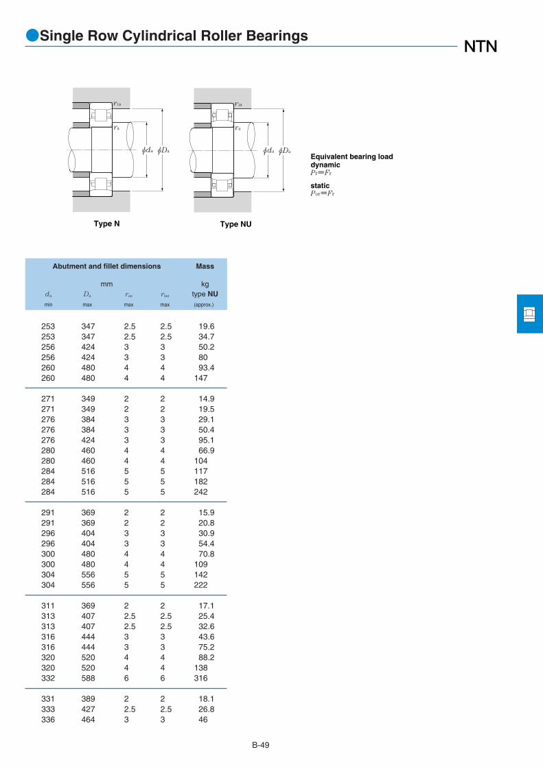
B-49
●Single Row Cylindrical Roller Bearings
Type NUType N
Pr=Fr
Equivalent bearing loaddynamic
Por=Frstatic
φda
ra
r1a
φDa φda
ra
r1a
φDa
Abutment and fillet dimensions Mass
mm kgda Da ras rlas type NUmin max max max (approx.)
253 347 2.5 2.5 19.6253 347 2.5 2.5 34.7256 424 3 3 50.2256 424 3 3 80260 480 4 4 93.4260 480 4 4 147
271 349 2 2 14.9271 349 2 2 19.5276 384 3 3 29.1276 384 3 3 50.4276 424 3 3 95.1280 460 4 4 66.9280 460 4 4 104284 516 5 5 117284 516 5 5 182284 516 5 5 242
291 369 2 2 15.9291 369 2 2 20.8296 404 3 3 30.9296 404 3 3 54.4300 480 4 4 70.8300 480 4 4 109304 556 5 5 142304 556 5 5 222
311 369 2 2 17.1313 407 2.5 2.5 25.4313 407 2.5 2.5 32.6316 444 3 3 43.6316 444 3 3 75.2320 520 4 4 88.2320 520 4 4 138332 588 6 6 316
331 389 2 2 18.1333 427 2.5 2.5 26.8336 464 3 3 46

B-50
●Single Row Cylindrical Roller Bearings
Boundary dimensions Basic load ratings Bearing Dimensionsdynamic static dynamic static numbers
mm kN kgf mmtype
d D B rs min1
rls min1
Cr Cor Cr Cor NU Fw
1 Minimal allowable dimension for chamfer dimension r or r1.
d 320~420mm
r r1
r
r1 r
r
r
r1
r
r r1
Type NU Type NJ Type NUP Type N Type NF
φd
r
r1
φD φFW
B
480 121 4 4 1,580 2,890 161,000 295,000 NU3064 358540 176 5 5 2,530 4,550 258,000 465,000 NU3164 376580 92 5 5 1,600 2,390 164,000 244,000 NU264 390580 150 5 5 2,550 4,350 260,000 445,000 NU2264 390670 200 7.5 7.5 3,750 5,800 385,000 595,000 NU2364 410
460 56 3 3 590 1,040 60,500 107,000 NU1968 370460 72 3 3 830 1,610 84,500 164,000 NU2968 370520 82 5 5 1,050 1,670 107,000 170,000 NU1068 385520 133 5 5 2,030 3,900 207,000 400,000 NU3068 385580 190 5 5 3,050 5,450 310,000 555,000 NU3168 400620 165 6 6 2,880 4,650 294,000 475,000 NU2268 410620 224 6 6 4,000 7,100 410,000 725,000 NU3268 410710 118 7.5 7.5 2,250 3,300 230,000 340,000 NU368 450710 212 7.5 7.5 4,250 6,600 430,000 675,000 NU2368 435
440 60 2.1 2.1 460 1,090 47,000 111,000 NU3872 382480 56 3 3 615 1,120 62,500 114,000 NU1972 390480 72 3 3 860 1,720 87,500 176,000 NU2972 390540 82 5 5 1,080 1,750 110,000 179,000 NU1072 405540 134 5 5 1,990 4,200 202,000 430,000 NU3072 413600 192 5 5 3,150 5,500 320,000 560,000 NU3172A 416650 232 6 6 4,150 7,600 425,000 775,000 NU3272 435750 224 7.5 7.5 4,500 7,000 460,000 710,000 NU2372 460
520 65 4 4 740 1,330 75,500 136,000 NU1976 416520 82 4 4 1,110 2,230 113,000 227,000 NU2976 416560 82 5 5 1,100 1,840 112,000 187,000 NU1076 425560 135 5 5 2,200 4,450 224,000 455,000 NU3076 426680 175 6 6 3,350 5,800 340,000 590,000 NU2276 460680 240 6 6 4,300 7,650 440,000 780,000 NU3276 460
500 75 2.1 2.1 870 2,250 88,500 229,000 NU3880 430600 90 5 5 1,320 2,190 134,000 223,000 NU1080 450600 148 5 5 2,520 5,050 257,000 515,000 NU3080 450
560 65 4 4 800 1,510 81,500 154,000 NU1984 456560 82 4 4 1,190 2,530 122,000 258,000 NU2984 456620 90 5 5 1,350 2,290 138,000 233,000 NU1084 470
400
420
380
360
340
320

B-51
●Single Row Cylindrical Roller Bearings
Type NUType N
Pr=Fr
Equivalent bearing loaddynamic
Por=Frstatic
φda
ra
r1a
φDa φda
ra
r1a
φDa
Abutment and fillet dimensions Mass
mm kgda Da ras rlas type NUmin max max max (approx.)
336 464 3 3 81.2340 520 4 4 175340 560 4 4 111340 560 4 4 172352 638 6 6 402
353 447 2.5 2.5 28.2353 447 2.5 2.5 36.2360 500 4 4 61.8360 500 4 4 108360 560 4 4 220364 596 5 5 260364 596 5 5 316372 678 6 6 246372 678 6 6 477
371 429 2 2 20.1373 467 2.5 2.5 29.6373 467 2.5 2.5 38380 520 4 4 64.7380 520 4 4 114380 580 4 4 232384 626 5 5 356392 718 6 6 562
396 504 3 3 42.9396 504 3 3 54.1400 540 4 4 67.5400 540 4 4 120404 656 5 5 326404 656 5 5 400
411 489 2 2 35.4420 580 4 4 87.6420 580 4 4 155
436 544 3 3 46.7436 544 3 3 59440 600 4 4 91

B-52
●Single Row Cylindrical Roller Bearings
Boundary dimensions Basic load ratings Bearing Dimensionsdynamic static dynamic static numbers
mm kN kgf mmtype
d D B rs min1
rls min1
Cr Cor Cr Cor NU Fw
1 Minimal allowable dimension for chamfer dimension r or r1.
d 440~670mm
r r1
r
r1 r
r
r
r1
r
r r1
Type NU Type NJ Type NUP Type N Type NF
φd
r
r1
φD φFW
B
600 95 4 4 1,520 3,100 155,000 320,000 NU2988 480650 94 6 6 1,430 2,430 146,000 248,000 NU1088 493650 157 6 6 2,770 5,700 283,000 580,000 NU3088 493
580 72 3 3 990 2,230 101,000 227,000 NU2892 490680 100 6 6 1,540 2,630 157,000 269,000 NU1092 516
650 78 5 5 1,140 2,150 116,000 219,000 NU1996 523650 100 5 5 1,640 3,450 168,000 350,000 NU2996 523700 100 6 6 1,580 2,750 161,000 280,000 NU1096 536
620 72 3 3 1,030 2,390 105,000 244,000 NU28/500 530670 78 5 5 1,160 2,220 118,000 226,000 NU19/500 543720 100 6 6 1,610 2,870 164,000 292,000 NU10/500 556
710 82 5 5 1,290 2,480 132,000 253,000 NU19/530 576710 106 5 5 1,870 4,000 191,000 410,000 NU29/530 576780 112 6 6 1,930 3,450 197,000 350,000 NU10/530 595780 185 6 6 3,650 7,400 375,000 755,000 NU30/530 590
680 72 3 3 1,090 2,680 111,000 273,000 NU28/560 590680 90 3 3 1,250 3,200 127,000 325,000 NU38/560 590750 85 5 5 1,470 2,840 150,000 290,000 NU19/560 607750 112 5 5 2,010 4,250 205,000 435,000 NU29/560 607820 115 6 6 2,190 3,900 223,000 400,000 NU10/560 626
730 78 3 3 1,210 3,000 124,000 310,000 NU28/600 633800 90 5 5 1,620 3,200 165,000 325,000 NU19/600 650800 118 5 5 2,270 4,950 231,000 505,000 NU29/600 650870 200 6 6 4,450 9,350 455,000 955,000 NU30/600 670
780 88 4 4 1,520 3,650 155,000 370,000 NU28/630 667850 100 6 6 1,910 3,700 195,000 380,000 NU19/630 684850 128 6 6 2,710 5,850 277,000 595,000 NU29/630 684920 128 7.5 7.5 2,560 4,650 261,000 475,000 NU10/630 705
820 88 4 4 1,580 3,900 161,000 395,000 NU28/670 707820 112 4 4 2,010 5,500 205,000 560,000 NU38/670 709900 103 6 6 1,980 3,950 202,000 405,000 NU19/670 729
630
670
600
500
530
560
480
460
440

B-53
●Single Row Cylindrical Roller Bearings
Type NUType N
Pr=Fr
Equivalent bearing loaddynamic
Por=Frstatic
φda
ra
r1a
φDa φda
ra
r1a
φDa
Abutment and fillet dimensions Mass
mm kgda Da ras rlas type NUmin max max max (approx.)
456 584 3 3 82.8464 626 5 5 105464 626 5 5 188
473 567 2.5 2.5 47.1484 656 5 5 122
500 630 4 4 78.5560 630 4 4 101504 676 5 5 126
513 607 2.5 2.5 50.7520 650 4 4 81.3524 696 5 5 130
550 690 4 4 95.9550 690 4 4 124554 756 5 5 192554 756 5 5 318
573 667 2.5 2.5 56.1573 667 2.5 2.5 72.7580 730 4 4 111580 730 4 4 146584 796 5 5 216
613 717 2.5 2.5 70.7620 780 4 4 132620 780 4 4 173624 846 5 5 416
646 764 3 3 97.5654 826 5 5 171654 826 5 5 218662 888 6 6 302
686 804 3 3 103686 804 3 3 136694 876 5 5 195

B-54
●Single Row Cylindrical Roller Bearings
Boundary dimensions Basic load ratings Bearing Dimensionsdynamic static dynamic static numbers
mm kN kgf mmtype
d D B rs min1
rls min1
Cr Cor Cr Cor NU Fw
1 Minimal allowable dimension for chamfer dimension r or r1.
d 670~1,250mm
r r1
r
r1 r
r
r
r1
r
r r1
Type NU Type NJ Type NUP Type N Type NF
φd
r
r1
φD φFW
B
900 136 6 6 2,940 6,600 300,000 675,000 NU29/670 729
950 106 6 6 2,260 4,600 231,000 465,000 NU19/710 770950 140 6 6 3,300 7,500 340,000 765,000 NU29/710 770
1,000 112 6 6 2,340 4,850 239,000 495,000 NU19/750 8151,000 145 6 6 3,600 8,400 365,000 860,000 NU29/750 815
980 106 5 5 2,310 5,950 236,000 605,000 NU28/800 8451,060 150 6 6 3,850 8,850 390,000 900,000 NU29/800 8651,150 155 7.5 7.5 4,100 7,800 415,000 795,000 NU10/800 887
1,030 106 5 5 2,390 6,350 244,000 645,000 NU28/850 8951,120 118 6 6 2,920 6,150 297,000 625,000 NU19/850 9171,120 155 6 6 4,000 9,250 410,000 945,000 NU29/850 917
1,400 195 7.5 7.5 6,100 14,500 620,000 1,480,000 NU29/1060 1,145
1,540 206 7.5 7.5 6,900 17,000 705,000 1,730,000 NU29/1180 1,270
1,630 170 7.5 7.5 5,550 12,500 565,000 1,280,000 NU19/1250 1,345
1,060
1,180
1,250
850
800
750
710
670

B-55
●Single Row Cylindrical Roller Bearings
Type NUType N
Pr=Fr
Equivalent bearing loaddynamic
Por=Frstatic
φda
ra
r1a
φDa φda
ra
r1a
φDa
Abutment and fillet dimensions Mass
mm kgda Da ras rlas type NUmin max max max (approx.)
694 876 5 5 257
734 926 5 5 221734 926 5 5 292
774 976 5 5 257774 976 5 5 332
820 960 4 4 178824 1,036 5 5 380832 1,118 6 6 554
870 1,010 4 4 188874 1,096 5 5 329874 1,096 5 5 432
1,092 1,368 6 6 855
1,212 1,508 6 6 1,060
1,282 1,598 6 6 975

B-56
●Multi-Row Cylindrical Roller Bearings
Boundary dimensions Basic load ratings Bearing numbersdynamic static dynamic static
mm kN kgf type NNU type NNCylindrical tapered Cylindrical tapered
d D B rs min2
Cr Cor Cr Cor bore bore1 bore bore1
1 "K" indicates bearings have tapered bore with a taper ratio of 1: 12. 2 Smallest allowable dimension for chamfer dimension r.
d 100~180mm
Type NNU
Cylindrical boreTapered bore
taper 1:12
Type NN
Cylindrical boreTapered bore
taper 1:12
r
r
B
r
r
φdφd φEwφD
B
φd φd φFWφD
140 40 1.1 131 260 13,300 26,500 NNU4920 NNU4920K NN4920 NN4920K150 37 1.5 153 256 15,600 26,100 - - NN3020 NN3020K
145 40 1.1 133 268 13,500 27,400 NNU4921 NNU4921K NN4921 NN4921K160 41 2 198 320 20,200 33,000 - - NN3021 NN3021K
150 30 1.1 107 206 10,900 21,000 - - NN3922 -150 40 1.1 137 284 14,000 28,900 NNU4922 NNU4922K NN4922 NN4922K170 45 2 229 375 23,300 38,000 NNU3022 NNU3022K NN3022 NN3022K
165 45 1.1 183 360 18,700 37,000 NNU4924 NNU4924K NN4924 NN4924K180 46 2 233 390 23,700 40,000 NNU3024 - NN3024 NN3024K
180 37 1.5 169 315 17,300 32,000 - - NN3926 NN3926K180 50 1.5 220 440 22,400 45,000 NNU4926 NNU4926K NN4926 NN4926K200 52 2 284 475 29,000 48,500 NNU3026 - NN3026 NN3026K210 64 2 340 560 35,000 57,000 - - NN3126 -
190 37 1.5 175 335 17,800 34,000 - - NN3928 -190 50 1.5 227 470 23,100 48,000 NNU4928 NNU4928K NN4928 NN4928K210 53 2 298 515 30,500 52,500 NNU3028 - NN3028 NN3028K
210 45 2 256 475 26,100 48,500 - - NN3930 -210 60 2 345 690 35,000 70,500 NNU4930 NNU4930K NN4930 NN4930K225 56 2.1 335 585 34,000 60,000 NNU3030 - NN3030 NN3030K225 75 2.1 435 825 44,500 84,000 - - NN4030 -250 80 2.1 555 900 56,500 92,000 NNU3130 - - -
220 45 2 265 505 27,000 51,500 - - NN3932 NN3932K220 60 2 355 740 36,500 75,500 NNU4932 NNU4932K NN4932 NN4932K240 60 2.1 375 660 38,000 67,500 - - NN3032 NN3032K
230 45 2 268 520 27,400 53,000 - - NN3934 NN3934K230 60 2 360 765 37,000 78,000 NNU4934 NNU4934K NN4934 NN4934K260 67 2.1 440 775 45,000 79,000 NNU3034 NNU3034K NN3034 NN3034K280 88 2.1 635 1,050 65,000 107,000 NNU3134 - NN3134 -
250 52 2 340 665 35,000 67,500 - - NN3936 NN3936K250 69 2 460 965 46,500 98,500 NNU4936 NNU4936K NN4936 NN4936K
100
105
110
120
130
140
150
160
170
180

B-57
●Multi-Row Cylindrical Roller Bearings
Type NN Type NNU
Pr=Fr
Por=Fr
Equivalent bearing loaddynamic
static
ra
ra
φda φDa
ra
ra
φda φDa
113 129 106.5 133.5 1 1.83 1.75- 137 108 - 1.5 - 2.26
118 134 111.5 138.5 1 1.91 1.82- 146 114 - 2 - 2.89
- 139 116.5 - 1 - 1.54123 139 116.5 143.5 1 1.99 1.9127 155 119 161 2 3.87 3.69
134.5 154.5 126.5 158.5 1 2.75 2.63137 165 129 171 2 4.24 3.98
- 168 138 - 1.5 - -146 168 138 172 1.5 3.69 3.52150 182 139 191 2 6.15 5.92- 189 139 - 2 - 8.59
- 178 148 - 1.5 - 3.01156 178 148 182 1.5 3.94 3.76160 192 149 201 2 6.64 6.44
- 196.5 159 - 2 - 4.79168.5 196.5 159 201 2 6.18 5.9172 206 161 214 2 8.06 7.81- 206 161 - 2 - 10.4
177 - 161 239 2 16.4 -
- 206.5 169 - 2 - 5.06178.5 206.5 169 211 2 6.53 6.24- 219 171 - 2 - 8.92
- 216.5 179 - 2 - 5.33188.5 216.5 179 221 2 6.87 6.56196 236 181 249 2 13.3 12.6201 253 181 269 2 22.3 21.5
- 234 189 - 2 - 7.72202 234 189 241 2 9.9 9.45
Dimensions Abutment and fillet dimensions Mass (approx.)
mm mm kgda Da ras type NNU type NN
Cylindrical CylindricalFw Ew min max max bore bore

B-58
●Multi-Row Cylindrical Roller Bearings
Boundary dimensions Basic load ratings Bearing numbersdynamic static dynamic static
mm kN kgf type NNU type NNCylindrical tapered Cylindrical tapered
d D B rs min2
Cr Cor Cr Cor bore bore1 bore bore1
1 "K" indicates bearings have tapered bore with a taper ratio of 1: 12. 2 Smallest allowable dimension for chamfer dimension r.
d 180~320mm
Type NNU
Cylindrical boreTapered bore
taper 1:12
Type NN
Cylindrical boreTapered bore
taper 1:12
r
r
B
r
r
φdφd φEwφD
B
φd φd φFWφD
280 74 2.1 565 995 57,500 102,000 NNU3036 - NN3036 NN3036K
260 52 2 355 705 36,000 72,000 - - NN3938 -260 69 2 475 1,030 48,500 105,000 NNU4938 NNU4938K NN4938 NN4938K290 75 2.1 580 1,040 59,000 106,000 NNU3038 - NN3038 NN3038K
280 60 2.1 445 890 45,500 91,000 - - NN3940 -280 80 2.1 555 1,180 56,500 120,000 NNU4940 NNU4940K NN4940 NN4940K310 82 2.1 655 1,170 66,500 119,000 NNU3040 - NN3040 NN3040K310 109 2.1 890 1,730 90,500 177,000 - - NN4040 -340 112 3 970 1,660 99,000 169,000 - - NN3140 -
300 60 2.1 470 975 48,000 99,500 - - NN3944 NN3944K300 80 2.1 585 1,300 59,500 132,000 NNU4944 NNU4944K NN4944 NN4944K340 90 3 815 1,480 83,000 151,000 NNU3044 - NN3044 NN3044K370 120 4 1,080 1,890 111,000 193,000 NNU3144 - NN3144 -
320 60 2.1 490 1,060 50,000 109,000 NNU3948 - NN3948 NN3948K320 80 2.1 610 1,410 62,500 144,000 NNU4948 NNU4948K NN4948 NN4948K360 92 3 855 1,600 87,000 163,000 NNU3048 - NN3048 NN3048K400 128 4 1,250 2,230 127,000 228,000 - - NN3148 -
360 75 2.1 660 1,390 67,000 141,000 - - NN3952 NN3952K360 100 2.1 900 2,070 92,000 211,000 NNU4952 NNU4952K NN4952 NN4952K400 104 4 1,060 1,990 108,000 203,000 - - NN3052 NN3052K400 140 4 1,500 3,100 153,000 315,000 NNU4052 - NN4052 -
350 52 2 320 765 32,500 78,000 NNU3856 - - -350 69 2 505 1,300 51,000 132,000 NNU4856 NNU4856K - -380 75 2.1 690 1,510 70,500 154,000 - - NN3956 NN3956K380 100 2.1 925 2,200 94,500 224,000 NNU4956 NNU4956K NN4956 NN4956K420 106 4 1,080 2,080 110,000 212,000 - - NN3056 NN3056K
420 90 3 945 2,050 96,000 209,000 - - NN3960 NN3960K420 118 3 1,200 2,800 122,000 285,000 NNU4960 NNU4960K NN4960 NN4960K460 118 4 1,330 2,560 135,000 261,000 NNU3060 - NN3060 NN3060K460 160 4 1,890 4,050 193,000 410,000 - - NN4060 -
400 80 2.1 610 1,600 62,500 163,000 NNU4864 - - -
190
200
220
240
260
280
300
320
180

B-59
●Multi-Row Cylindrical Roller Bearings
Type NN Type NNU
Pr=Fr
Por=Fr
Equivalent bearing loaddynamic
static
ra
ra
φda φDa
ra
ra
φda φDa
209 255 191 269 2 17.4 16.6
- 244 199 - 2 - 8.08212 244 199 251 2 10.4 9.93219 265 201 279 2 18.4 18
- 261 211 - 2 - 11.4225 261 211 269 2 14.7 14232 282 211 299 2 23.5 21.6- 282 211 - 2 - 30.2- 304 213 - 2.5 - 41.8
- 281 231 - 2 - 12.3245 281 231 289 2 15.9 15.2254 310 233 327 2.5 31.0 29.3263.5 331.5 236 354 3 54.4 52.4
265 301 251 309 2 13.8 13.3265 301 251 309 2 17.2 16.4274 330 253 347 2.5 33.9 32.8- 361 256 - 3 - 64.7
- 336 271 - 2 - 22.9292 336 271 349 2 29.6 28.3- 364 276 - 3 - 47.4
298 362 276 384 3 66.2 63.8
301 - 289 341 2 11.7 -301 - 289 341 2 15.6 -- 356 291 - 2 - 24.4
312 356 291 369 2 31.6 30.2- 384 296 - 3 - 51.1
- 391 313 - 2.5 - 38.4339 391 313 407 2.5 48.6 46.4346 418 316 444 3 73.4 70.8- 418 316 - 3 - 96
344 - 331 389 2 23.6 -
Dimensions Abutment and fillet dimensions Mass (approx.)
mm mm kgda Da ras type NNU type NN
Cylindrical CylindricalFw Ew min max max bore bore

B-60
●Multi-Row Cylindrical Roller Bearings
Boundary dimensions Basic load ratings Bearing numbersdynamic static dynamic static
mm kN kgf type NNU type NNCylindrical tapered Cylindrical tapered
d D B rs min2
Cr Cor Cr Cor bore bore1 bore bore1
1 "K" indicates bearings have tapered bore with a taper ratio of 1: 12. 2 Smallest allowable dimension for chamfer dimension r.
d 320~500mm
Type NNU
Cylindrical boreTapered bore
taper 1:12
Type NN
Cylindrical boreTapered bore
taper 1:12
r
r
B
r
r
φdφd φEwφD
B
φd φd φFWφD
440 90 3 975 2,180 99,000 222,000 - - NN3964 NN3964K440 118 3 1,240 2,970 126,000 305,000 NNU4964 NNU4964K NN4964 NN4964K480 121 4 1,350 2,670 138,000 272,000 NNU3064 - NN3064 NN3064K540 176 5 2,160 3,950 220,000 400,000 NNU3164 - - -
460 118 3 1,280 3,150 131,000 320,000 NNU4968 NNU4968K NN4968 NN4968K520 133 5 1,620 3,200 165,000 325,000 NNU3068 - NN3068 NN3068K
480 90 3 1,030 2,430 105,000 248,000 - - NN3972 -480 118 3 1,290 3,250 131,000 330,000 NNU4972 NNU4972K - -540 134 5 1,650 3,300 169,000 340,000 NNU3072 - NN3072 NN3072K540 180 5 2,470 5,550 252,000 570,000 NNU4072 - - -
520 140 4 1,630 4,050 167,000 415,000 NNU4976 NNU4976K - -560 135 5 1,690 3,450 172,000 355,000 NNU3076 - NN3076 NN3076K
500 100 2.1 1,070 2,950 109,000 300,000 NNU4880 - - -540 140 4 1,690 4,300 172,000 435,000 NNU4980 NNU4980K - -600 148 5 2,040 4,150 208,000 420,000 - - NN3080 NN3080K
560 106 4 1,370 3,350 140,000 340,000 - - NN3984 -560 140 4 1,740 4,500 177,000 460,000 NNU4984 NNU4984K - -620 150 5 2,080 4,300 212,000 440,000 - - NN3084 NN3084K700 224 6 3,400 6,400 345,000 650,000 NNU3184 - - -
600 160 4 2,150 5,550 219,000 565,000 NNU4988 NNU4988K - -650 157 6 2,420 5,100 247,000 520,000 NNU3088 - NN3088 NN3088K650 212 6 3,250 7,750 330,000 790,000 NNU4088 - - -
620 160 4 2,220 5,850 226,000 595,000 NNU4992 NNU4992K - -680 163 6 2,550 5,350 260,000 545,000 - - NN3092 NN3092K
600 90 3 1,010 2,570 103,000 262,000 - - NN3896 -650 170 5 2,280 5,900 233,000 600,000 NNU4996 NNU4996K - -790 248 7.5 4,100 8,100 420,000 825,000 - - NN3196 -
620 90 3 1,140 2,880 116,000 293,000 NNU38/500 - - -670 170 5 2,360 6,200 240,000 635,000 NNU49/500 NNU49/500K - -720 167 6 2,650 5,750 270,000 590,000 - - NN30/500 -
340
360
380
400
420
440
460
480
500
320

B-61
●Multi-Row Cylindrical Roller Bearings
Type NN Type NNU
Pr=Fr
Por=Fr
Equivalent bearing loaddynamic
static
ra
ra
φda φDa
ra
ra
φda φDa
- 411 333 - 2.5 - 40.5359 411 333 427 2.5 51.4 49366 438 336 464 3 79.3 76.2383 - 340 520 4 170 -
379 431 353 447 2.5 54.2 52.2393 473 360 500 4 105 102
- 451 373 - 2.5 - 44.8398 - 373 467 2.5 57 -413 493 380 520 4 111 107415 - 380 520 4 136 -
425 - 396 504 3 84.5 -432 512 400 540 4 117 113
430.5 - 411 489 2 46.1 -445 - 416 524 3 88.2 -- 547 420 - 4 - 146
- 522 436 - 3 - 71.7465 - 436 544 3 92 -- 567 440 - 4 - 154
500 - 444 676 5 359 -
492 - 456 584 3 127 -500 596 464 626 5 184 178505 - 464 626 5 248 -
512 - 476 604 3 132 -- 622 484 - 5 - 202
- 566 493 - 2.5 - 57.5534 - 500 630 4 156 -- 710 512 - 6 - 482
532 - 513 607 2.5 61.9 -556 - 520 650 4 162 -- 664 524 - 5 - 221
Dimensions Abutment and fillet dimensions Mass (approx.)
mm mm kgda Da ras type NNU type NN
Cylindrical CylindricalFw Ew min max max bore bore

B-62
●Multi-Row Cylindrical Roller Bearings
Boundary dimensions Basic load ratings Bearing numbersdynamic static dynamic static
mm kN kgf type NNU type NNCylindrical tapered Cylindrical tapered
d D B rs min2
Cr Cor Cr Cor bore bore1 bore bore1
1 "K" indicates bearings have tapered bore with a taper ratio of 1: 12. 2 Smallest allowable dimension for chamfer dimension r.
d 530~950mm
Type NNU
Cylindrical boreTapered bore
taper 1:12
Type NN
Cylindrical boreTapered bore
taper 1:12
r
r
B
r
r
φdφd φEwφD
B
φd φd φFWφD
650 90 3 1,060 2,840 108,000 289,000 - - NN38/530 -710 180 5 2,740 7,150 279,000 730,000 NNU49/530 NNU49/530K - -
680 90 3 1,060 2,960 108,000 300,000 - - NN38/560 -750 190 5 3,150 8,450 325,000 860,000 NNU49/560 NNU49/560K NN49/560 -820 195 6 3,550 7,700 365,000 785,000 NNU30/560 - - -
730 128 3 1,840 5,400 188,000 550,000 NNU48/600 - - -870 200 6 3,700 8,250 375,000 845,000 - - NN30/600 -
780 150 4 2,200 6,200 224,000 630,000 NNU48/630 - - -850 165 6 5,750 5,300 585,000 1,560,000 NNU39/630 - - -
920 128 5 2,340 6,450 238,000 660,000 NNU38/750 - - -1,000 250 6 4,850 3,200 495,000 1,340,000 NNU49/750 - - -
980 136 5 2,430 6,700 248,000 680,000 NNU38/800 - - -1,060 195 6 3,900 10,200 400,000 1,040,000 NNU39/800 - - -
1,250 300 7.5 7,150 1,200 730,000 2,160,000 - - NN49/950 -
530
560
600
630
750
800
950

B-63
●Multi-Row Cylindrical Roller Bearings
Type NN Type NNU
Pr=Fr
Por=Fr
Equivalent bearing loaddynamic
static
ra
ra
φda φDa
ra
ra
φda φDa
- 616 543 - 2.5 - 62.9588 - 550 690 4 206 -
- 647 573 - 2.5 - 66.1618 702 580 730 4 242 233634 - 584 796 5 358 -
635 - 613 717 2.5 113 -- 800 624 - 5 - 392
673 - 646 764 3 162 -684 - 654 826 5 275 -
798 - 770 900 4 186 -824 - 774 976 5 560 -
852 - 820 960 4 223 -878 - 824 1,036 5 483 -
- 1,176 982 - 6 - 977
Dimensions Abutment and fillet dimensions Mass (approx.)
mm mm kgda Da ras type NNU type NN
Cylindrical CylindricalFw Ew min max max bore bore

B-64
●4-Row Cylindrical Roller Bearings
Boundary dimensions Basic load ratings Bearing1 Drawing2
dynamic static dynamic static numbers No.mm kN kgf
d D B1 C1 rs min3
rls min3
Cr Cor Cr Cor
1 "K" indicates bearings have tapered bore with a taper ratio of 1: 12. 2 Drawing details are shown in Page B-38.3 Minimal allowable dimension for chamfer dimension r or r1.
d 100~170mm
C1
φd
r1
B1
φD φFW
r
150 74 74 2 2 262 510 26,700 52,500 4R2035 A
180 92 92 2.5 2.5 400 785 40,500 80,000 4R2437 A180 105 105 2.5 2.5 445 855 45,500 87,000 4R2438 A
200 104 104 2.5 2.5 490 955 49,500 97,000 4R2628 A
190 119 119 1.5 1.5 495 1,190 50,500 121,000 4R2832 B2)
210 116 116 2.5 2.5 510 1,030 52,000 105,000 4R2823 A
210 155 155 2.5 2.5 705 1,640 71,500 168,000 4R2906 A225 156 156 2.5 2.5 810 1,750 82,500 178,000 4R2904 A
220 127 120 2.5 2.5 615 1,280 63,000 130,000 4R3036 A220 150 150 2.5 2.5 750 1,640 76,500 168,000 4R3031 A220 150 150 2.5 2.5 750 1,640 76,500 168,000 4R3056 A230 130 130 2.5 2.5 725 1,520 73,500 155,000 4R3029 A230 156 156 2.5 2.5 930 2,040 95,000 208,000 4R3040 A230 168 168 2 2 845 1,950 86,000 199,000 4R3042 A250 150 150 2.5 2.5 885 1,640 90,500 167,000 4R3039 A
230 168 168 1.5 2.5 850 2,060 87,000 210,000 4R3033K A
220 180 180 2.5 2.5 920 2,490 93,500 254,000 4R3224 D3)
230 130 130 2.5 2.5 665 1,340 68,000 136,000 4R3226 A230 168 168 2.5 2.5 915 2,170 93,500 222,000 4R3232 A230 168 168 2.5 2.5 895 2,200 91,500 225,000 4R3229 A230 168 168 2.5 2.5 895 2,210 91,000 225,000 4R3231 A230 180 180 2.5 2.5 920 2,490 93,500 254,000 4R3228 D3)
240 170 170 2 2.5 980 2,290 100,000 234,000 4R3225 A
230 120 120 2.5 2.5 620 1,520 63,000 155,000 4R3426 A230 120 120 2 2 620 1,520 63,000 155,000 4R3443 C240 156 156 2.5 2.5 905 2,170 92,500 222,000 4R3429 A240 160 160 2.5 2.5 905 2,180 92,000 222,000 4R3423 A250 168 168 2.5 2.5 970 2,220 99,000 226,000 4R3432 A250 168 168 2.5 2.5 1,030 2,390 105,000 243,000 4R3428 A255 180 180 2.5 2.5 1,100 2,430 112,000 247,000 4R3425 A260 150 150 2.5 2.5 835 1,750 85,000 179,000 4R3433 A
100
120
130
140
145
150
151.5
160
170

B-65
Abutment and fillet dimensions Mass
mm kgda Da ras rlas
Fw min max max max (approx.)
●4-Row Cylindrical Roller Bearings
φDa
r1a
ra
φda
115 109 141 2.0 2.0 4.68
137 131 169 2 2 8.2135 131 169 2 2 9.3
150 141 189 2 2 12.1
154 148 182 1.5 1.5 9.93160 151 199 2 2 13.9
166 156 199 2 2 18169 156 214 2 2 23.3
168 161 209 2 2 15.7168 161 209 2 2 19.4168 161 209 2 2 19.6174 161 219 2 2 20174 161 219 2 2 24.5178 159 221 2 2 25.8177 161 239 2 2 29.6
179 159.5 219 1.5 2 25.4
177 171 209 2 2 20.2180 171 219 2 2 16.6179 171 219 2 2 23.4180 171 219 2 2 23.2182 171 219 2 2 23.2177 171 219 2 2 24.8183 169 229 2 2 27.8
187 181 219 2 2 14.2187 179 221 2 2 14.6189 181 229 2 2 22.2190 181 229 2 2 22.8193 181 239 2 2 28.2193 181 239 2 2 28.5193 181 244 2 2 19.3192 181 249 2 2 29.5

B-66
●4-Row Cylindrical Roller Bearings
Boundary dimensions Basic load ratings Bearing1 Drawing2
dynamic static dynamic static numbers No.mm kN kgf
d D B1 C1 rs min3
rls min3
Cr Cor Cr Cor
1 Drawing details are shown in Page B-38.2 Minimal allowable dimension for chamfer dimension r or r1.
d 170~230mm
C1
φd
r1
B1
φD φFW
r
260 225 225 2.5 2.5 1,310 3,150 134,000 320,000 4R3431 A
250 156 156 2.5 2.5 895 2,180 91,500 223,000 4R3625 A250 168 168 2 2 885 2,470 90,000 252,000 4R3639 A260 168 168 2.5 2.5 1,020 2,400 104,000 244,000 4R3628 A265 180 180 2.5 2.5 1,090 2,510 111,000 256,000 4R3618 A
260 168 168 2.5 2.5 980 2,600 100,000 265,000 4R3820 A270 170 170 2.5 2.5 1,090 2,660 111,000 272,000 4R3818 A270 200 200 2.5 2.5 1,260 3,100 128,000 315,000 4R3821 A270 200 200 2.5 2.5 1,230 3,200 125,000 330,000 4R3817 A280 200 200 2.5 2.5 1,240 2,910 126,000 297,000 4R3823 B280 200 200 2.5 2.5 1,240 2,910 126,000 297,000 4R3830 C
270 170 170 2.5 2.5 970 2,610 99,000 266,000 4R4039 A280 152 152 2.1 2.1 1,000 2,320 102,000 237,000 4R4054 B2)
280 170 170 2.5 2.5 1,040 2,430 106,000 248,000 4R4048 A280 190 190 2.5 2.5 1,190 3,150 121,000 320,000 4R4026 A280 200 200 2.5 2.5 1,310 3,300 134,000 335,000 4R4037 A280 200 200 2.5 2.5 1,250 3,350 127,000 340,000 4R4027 A290 192 192 2.5 2.5 1,290 3,150 132,000 320,000 4R4041 A
290 192 192 2.5 2.5 1,230 3,350 126,000 340,000 4R4206 A
290 192 192 2.5 2.5 1,190 3,350 122,000 340,000 4R4413 A300 160 160 2.5 2.5 1,000 2,590 102,000 264,000 4R4419 A300 160 160 2.1 2.1 1,000 2,590 102,000 264,000 4R4445 C310 192 192 2.5 2.5 1,350 3,550 138,000 360,000 4R4410 A310 192 192 2.5 2.5 1,390 3,400 141,000 350,000 4R4426 A310 204 204 2.5 2.5 1,420 3,750 144,000 385,000 4R4425 A310 215 215 2.5 2.5 1,530 3,750 156,000 380,000 4R4420 A310 225 225 2.5 2.5 1,480 3,950 151,000 405,000 4R4416 A310 225 225 2.5 2.5 1,590 3,950 162,000 400,000 4R4449 A320 160 160 3 3 1,190 2,550 121,000 260,000 4R4428 A320 210 210 2.5 2.5 1,550 3,650 158,000 370,000 4R4429 A320 210 210 2.5 2.5 1,560 3,600 159,000 370,000 4R4444 A
330 206 206 2.5 2.5 1,510 3,900 154,000 395,000 4R4610 A330 206 206 2.5 2.5 1,520 3,800 155,000 385,000 4R4614 A
170
180
190
200
210
230
220

B-67
Abutment and fillet dimensions Mass
mm kgda Da ras rlas
Fw min max max max (approx.)
●4-Row Cylindrical Roller Bearings
φDa
r1a
ra
φda
196 181 249 2 2 44
200 191 239 2 2 23.2202 189 241 2 2 25.6202 191 249 2 2 29.4204 191 254 2 2 34.2
212 201 249 2 2 26.9213 201 259 2 2 31.7212 201 259 2 2 37.5212 201 259 2 2 37.2214 201 269 2 2 41.5214 201 269 2 2 42.8
222 211 259 2 2 28.5222 211 269 2 2 29.5222 211 269 2 2 33223 211 269 2 2 36.7222 211 269 2 2 40.5224 211 269 2 2 38.8226 211 279 2 2 42.5
236 221 279 2 2 39.5
239 231 279 2 2 33.8245 231 289 2 2 32.8245 231 289 2 2 33.7247 231 299 2 2 46.3246 231 299 2 2 46.9247 231 299 2 2 49.8242 231 299 2 2 51.5245 231 299 2 2 54.9244 231 299 2 2 54.3245 233 307 2.5 2.5 46.5248 231 309 2 2 60.5246 231 309 2 2 57.3
260 241 319 2 2 58.3258 241 319 2 2 58.6

B-68
●4-Row Cylindrical Roller Bearings
Boundary dimensions Basic load ratings Bearing Drawing1
dynamic static dynamic static numbers No.mm kN kgf
d D B1 C1 rs min2
rls min2
Cr Cor Cr Cor
1 Drawing details are shown in Page B-38.2 Minimal allowable dimension for chamfer dimension r or r1.
d 230~300mm
C1
φd
r1
B1
φD φFW
r
340 260 260 3 3 2,050 5,100 209,000 520,000 4R4611 A
330 220 220 3 3 1,490 4,150 152,000 420,000 4R4811 C330 220 220 3 3 1,610 4,250 164,000 435,000 4R4819 A330 220 220 3 3 1,490 4,150 152,000 420,000 4R4821 C330 220 220 3 3 1,520 4,250 155,000 435,000 4R4804 A340 220 220 3 3 1,670 4,200 170,000 425,000 4R4806 A360 220 220 2.5 2.5 1,760 4,050 179,000 415,000 4R4807 A360 220 220 2.5 2.5 1,760 4,050 179,000 415,000 4R4813 A
350 220 220 3 3 1,730 4,300 176,000 440,000 4R5008 A
360 220 200 2.5 2.5 1,540 4,150 157,000 426,000 4R5221 D360 260 260 2.5 2.1 1,830 4,850 187,000 495,000 4R5231 C1)
370 220 220 3 3 1,760 4,450 179,000 455,000 4R5208 A370 220 220 3 3 1,760 4,450 179,000 455,000 4R5217 A1)
380 280 280 3 3 2,420 6,250 247,000 635,000 4R5213 A400 290 290 4 2 3,050 7,150 315,000 730,000 4R5218 E4)
370 234 234 1.5 1.5 2,020 5,000 206,000 510,000 4R5306 A1)
380 280 280 2.5 2.5 2,260 5,750 231,000 585,000 4R5407 A380 280 280 2.5 2.5 2,580 6,850 263,000 700,000 4R5405 F4)
350 208 208 2.5 2.5 1,290 3,950 132,000 405,000 4R5614 A390 220 220 3 3 1,780 4,650 181,000 475,000 4R5611 A390 220 220 3 3 1,820 4,800 186,000 490,000 4R5604 A390 275 275 2.5 2.5 2,290 6,250 233,000 635,000 4R5612 D3)
420 280 280 4 4 2,430 6,150 248,000 630,000 4R5605 A
410 240 240 3 3 2,240 5,550 228,000 565,000 4R5806 A420 300 300 3 3 2,830 7,500 288,000 765,000 4R5805 A
400 300 300 3 3 2,480 7,500 253,000 765,000 4R6014 A420 240 240 3 3 2,020 5,450 206,000 555,000 4R6017 A1)
420 240 240 3 3 2,020 5,450 206,000 555,000 4R6012 A420 240 240 3 3 2,010 5,450 205,000 555,000 4R6023 A1)
420 240 240 3 3 2,280 5,750 233,000 585,000 4R6027 A420 300 300 3 3 2,990 8,150 305,000 835,000 4R6030 F1)
230
240
250
260
265
270
280
290
300

B-69
Abutment and fillet dimensions Mass
mm kgda Da ras rlas
Fw min max max max (approx.)
●4-Row Cylindrical Roller Bearings
φDa
r1a
ra
φda
261 243 327 2.5 2.5 82.6
270 253 317 2.5 2.5 56.8264 253 317 2.5 2.5 57.1268 253 317 2.5 2.5 57.1270 253 317 2.5 2.5 57.1268 253 327 2.5 2.5 63.6274 251 349 2 2 79.6274 251 349 2 2 80.1
278 263 337 2.5 2.5 66
292 271 349 2 2 62.7287 271 349 2 2 81.5292 273 357 2.5 2.5 77.1292 273 357 2.5 2.5 76.5294 273 367 2.5 2.5 109296 276 391 3 2 135
300 273 362 1.5 1.5 78.9
297 281 369 2 2 101299.7 281 369 2 2 105
298 291 339 2 2 46.4312 293 377 2.5 2.5 81.3312 293 377 2.5 2.5 82312 291 379 2 2 105323 296 404 3 3 139
320 303 397 2.5 2.5 103327 303 407 2.5 2.5 141
328 313 387 2.5 2.5 104334 313 407 2.5 2.5 106334 313 407 2.5 2.5 105336 313 407 2.5 2.5 105332 313 407 2.5 2.5 105331 313 407 2.5 2.5 136

B-70
●4-Row Cylindrical Roller Bearings
Boundary dimensions Basic load ratings Bearing1 Drawing2
dynamic static dynamic static numbers No.mm kN kgf
d D B1 C1 rs min3
rls min3
Cr Cor Cr Cor
1 "K" indicates bearings have tapered bore with a taper ratio of 1: 12. 2 Drawing details are shown in Page B-38.3 Minimal allowable dimension for chamfer dimension r or r1.
d 300~380mm
C1
φd
r1
B1
φD φFW
r
420 300 300 3 3 2,720 7,600 278,000 775,000 4R6015 A420 300 300 3 3 2,900 7,850 295,000 800,000 4R6020 F1)
420 320 300 3 3 2,900 7,850 295,000 800,000 4R6018 F2)
430 240 240 3 3 2,160 5,150 220,000 525,000 4R6021 A460 270 270 3 3 2,510 5,350 256,000 545,000 4R6019 A
430 240 240 3 3 2,240 5,950 228,000 605,000 4R6202 A
440 240 230 3 3 2,290 6,050 234,000 615,000 4R6414 A450 240 240 3 3 2,370 6,150 242,000 630,000 4R6411 A460 340 340 3 3 3,400 9,450 345,000 960,000 4R6412 A470 350 350 3 3 4,150 10,900 425,000 1,110,000 4R6406 F4)
440 200 200 3 3 1,820 4,850 186,000 495,000 4R6603 B440 200 200 5 3 1,720 4,550 176,000 465,000 4R6608 B1)
460 340 340 4 4 3,250 8,850 330,000 905,000 4R6605 A460 340 340 4 4 3,300 9,550 335,000 975,000 4R6602 A
480 350 350 4 4 3,950 10,900 400,000 1,110,000 4R6819 FM1)
480 370 350 5 5 3,450 9,650 350,000 985,000 4R6811 A490 300 300 4 4 3,350 8,300 340,000 845,000 4R6804 A490 300 300 5 5 3,100 7,950 315,000 810,000 4R6805 A
550 400 400 4 4 5,100 13,800 520,000 1,410,000 4R7105K E
480 290 290 3 3 2,990 8,150 305,000 830,000 4R7207 A510 370 370 4 4 3,550 9,700 365,000 990,000 4R7212 C510 400 380 4 2 4,350 11,900 445,000 1,210,000 4R7205 E1)
510 400 400 5 5 4,250 11,500 435,000 1,170,000 4R7203 B
480 230 230 5 5 2,100 6,250 214,000 635,000 4R7405 A480 250 250 3 3 2,200 6,450 225,000 660,000 4R7408 A520 380 380 5 5 3,900 10,800 400,000 1,100,000 4R7411 A520 400 400 5 5 4,650 13,500 475,000 1,370,000 4R7404 A
520 280 280 4 4 3,400 9,150 350,000 935,000 4R7605 A520 290 290 4 4 3,400 9,150 350,000 935,000 4R7617 A520 300 300 4 4 3,550 9,600 360,000 980,000 4R7607 G1)
540 400 400 4 4 5,200 15,200 530,000 1,550,000 4R7604 G2)
300
310
320
330
340
356.76
360
370
380

B-71
Abutment and fillet dimensions Mass
mm kgda Da ras rlas
Fw min max max max (approx.)
●4-Row Cylindrical Roller Bearings
φDa
r1a
ra
φda
334 313 407 2.5 2.5 125332 313 407 2.5 2.5 130332 313 407 2.5 2.5 136338 313 417 2.5 2.5 115344 313 447 2.5 2.5 162
344.5 323 417 2.5 2.5 108
351 333 427 2.5 2.5 106358 333 437 2.5 2.5 125360 333 447 2.5 2.5 178361.7 333 457 2.5 2.5 212
360 343 427 2.5 2.5 83.6360 350 427 4 2.5 85.6365 346 444 3 3 181368 346 444 3 3 177
378 356 464 3 3 211378 360 460 4 4 198377 356 474 3 3 187380 360 470 4 4 189
426 372.757 534 3 3 354
388 373 467 2.5 2.5 148400 376 494 3 3 244399 376 509 3 2 251397 380 490 4 4 262
400 390 460 4 4 106401 383 467 2.5 2.5 118409 390 500 4 4 256409 390 500 4 4 273
417 396 504 3 3 174417 396 504 3 3 185416 396 504 3 3 210422 396 524 3 3 325

B-72
●4-Row Cylindrical Roller Bearings
Boundary dimensions Basic load ratings Bearing Drawing1
dynamic static dynamic static numbers No.mm kN kgf
d D B1 C1 rs min2
rls min2
Cr Cor Cr Cor
1 Drawing details are shown in Page B-38.2 Minimal allowable dimension for chamfer dimension r or r1.
d 380~500mm
C1
φd
r1
B1
φD φFW
r
540 400 400 4 4 4,950 14,400 505,000 1,470,000 4R7618 FM1)
540 400 400 5 5 4,550 12,700 465,000 1,300,000 4R7613 B1)3)
560 400 400 5 5 4,250 11,800 430,000 1,210,000 4R8007 B560 410 410 4 4 5,750 17,000 585,000 1,730,000 4R8010 F590 420 420 4 4 5,150 13,000 525,000 1,330,000 4R8011 A
560 280 280 4 4 3,150 8,750 320,000 895,000 4R8403 A580 230 230 4 4 2,430 6,250 248,000 635,000 4R8404 A600 440 440 6 2.5 6,350 18,100 650,000 1,850,000 4R8407 F1)
620 400 400 5 5 5,000 13,400 510,000 1,360,000 4R8401 D3)
591 420 420 5 5 5,500 17,400 560,000 1,770,000 4R8605 FM1)4)
600 450 450 1.5 5 6,000 17,900 615,000 1,820,000 4R8806 FR2)
600 450 450 1.5 5 6,350 19,100 645,000 1,950,000 4R8805 FR1)
620 450 450 5 5 6,450 18,700 660,000 1,910,000 4R8803 F1)
620 450 450 5 5 6,450 18,700 660,000 1,910,000 4R8801 F
620 400 400 4 4 5,350 16,700 545,000 1,700,000 4R9211 GS620 400 400 4 4 4,950 15,000 505,000 1,530,000 4R9209 A620 460 460 4 4 5,950 19,100 605,000 1,950,000 4R9223 FM1)
650 470 470 5 5 7,150 20,600 730,000 2,100,000 4R9216 F1)
660 470 470 5 5 7,300 21,300 745,000 2,170,000 4R9403 FM1)
600 236 236 3 3 2,620 7,850 267,000 805,000 4R9610 A650 420 420 5 5 5,700 17,200 585,000 1,750,000 4R9613 G1)
650 420 420 5 5 5,950 18,100 605,000 1,840,000 4R9607 G680 500 500 6 6 7,950 24,000 810,000 2,450,000 4R9604 F
680 420 405 5 5 7,100 22,900 725,000 2,340,000 4R10010 F2)
680 420 405 5 5 6,300 18,800 640,000 1,920,000 4R10020 F2)
690 470 470 5 5 7,650 22,500 780,000 2,290,000 4R10016 F1)
690 510 510 5 5 7,750 24,600 790,000 2,500,000 4R10006 F700 515 515 5 5 7,900 24,100 805,000 2,450,000 4R10011 F710 480 480 6 6 8,650 24,700 880,000 2,520,000 4R10008 F1)
720 530 530 5 5 8,250 25,000 840,000 2,550,000 4R10015 F1)
720 530 530 5 5 8,250 25,000 840,000 2,550,000 4R10024 FM1)
380
400
420
430
440
460
470
480
500

B-73
Abutment and fillet dimensions Mass
mm kgda Da ras rlas
Fw min max max max (approx.)
●4-Row Cylindrical Roller Bearings
φDa
r1a
ra
φda
422 396 524 3 3 309424 400 520 4 4 298
446 420 540 4 4 303445 416 544 3 3 349450 416 574 3 3 399
457 436 544 3 3 189466 436 564 3 3 181469.6 444 589 5 2 423478 440 600 4 4 410
476 450 571 4 4 362
480 448 580 1.5 4 392480 448 580 1.5 4 392487 460 600 4 4 450487 460 600 4 4 437
502 476 604 3 3 383502 476 604 3 3 341502 476 604 3 3 417509 480 630 4 4 540
517 490 640 4 4 529
510 493 587 2.5 2.5 155523 500 630 4 4 423523 500 630 4 4 369532 504 656 5 5 640
550 520 660 4 4 495550 520 660 4 4 451547 520 670 4 4 590552 520 670 4 4 640554 520 680 4 4 680556 524 686 5 5 675568 520 700 4 4 780568 520 700 4 4 745

B-74
●4-Row Cylindrical Roller Bearings
Boundary dimensions Basic load ratings Bearing Drawing1
dynamic static dynamic static numbers No.mm kN kgf
d D B1 C1 rs min2
rls min2
Cr Cor Cr Cor
1 Drawing details are shown in Page B-38.2 Minimal allowable dimension for chamfer dimension r or r1.
d 510~680mm
C1
φd
r1
B1
φD φFW
r
670 320 320 5 5 4,550 13,500 465,000 1,380,000 4R10201 G1)
700 540 540 6 6 8,300 25,000 845,000 2,550,000 4R10202 F1)
700 540 540 6 6 8,200 25,500 835,000 2,600,000 4R10403 F1)
720 550 550 5 5 9,400 27,700 960,000 2,820,000 4R10406 FR1)
735 535 535 5 5 9,000 26,600 915,000 2,710,000 4R10402 F2)
700 540 540 6 6 7,850 25,400 800,000 2,590,000 4R10603 F1)
760 520 520 6 6 9,150 26,700 935,000 2,730,000 4R10601 F1)
780 570 570 6 6 10,300 29,100 1,050,000 2,970,000 4R10602 F1)
780 570 570 7.5 6 10,300 29,100 1,050,000 2,970,000 4R10606 FM1)
762.03 558.8 558.8 5 6 10,100 29,200 1,030,000 2,980,000 4R10704 F2)
800 520 520 6 6 9,450 27,000 965,000 2,750,000 4R11001 F1)
680 360 360 3 3 4,650 16,500 475,000 1,680,000 4R11202 A
800 514 514 2.5 6 10,200 29,200 1,040,000 2,970,000 4R11404 FR1)
815 594 594 6 6 11,800 34,500 1,200,000 3,500,000 4R11402 F
820 575 575 7.5 7.5 10,000 31,500 1,020,000 3,200,000 4R12006 FM1)
870 540 540 7.5 7.5 10,600 29,600 1,090,000 3,000,000 4R12002 F1)
870 640 640 7.5 7.5 13,600 40,500 1,390,000 4,150,000 4R12001 F
870 660 660 9.5 7.5 12,600 40,000 1,280,000 4,100,000 4R12202 F1)4)
922 600 600 3 6 13,600 38,500 1,390,000 3,900,000 4R12602 F1)
880 600 600 6 6 11,500 36,000 1,170,000 3,650,000 4R12802 F2)
920 670 670 7.5 4 14,600 46,000 1,490,000 4,700,000 4R13005 F1)
920 680 680 7.5 7.5 14,800 47,000 1,520,000 4,800,000 4R13010 FR1)
920 690 690 7.5 7.5 14,300 46,500 1,460,000 4,750,000 4R13003 F
820 440 440 5 4 7,300 27,800 745,000 2,840,000 4R13201 F
1,020 650 650 6 6 15,700 48,000 1,600,000 4,900,000 4R13603 FM2)
1,020 680 680 3 5 17,300 49,500 1,760,000 5,050,000 4R13604 F2)
510
520
530
536.18
550
560
570
600
610
628
640
660
680
650

B-75
Abutment and fillet dimensions Mass
mm kgda Da ras rlas
Fw min max max max (approx.)
●4-Row Cylindrical Roller Bearings
φDa
r1a
ra
φda
554 530 650 4 4 335558 534 676 5 5 689
564 544 676 5 5 658566 540 700 4 4 715574.5 540 715 4 4 740
574 554 676 5 5 626590 554 736 5 5 800601 554 756 5 5 1,010595 562 756 6 5 978
600 556.176 738.03 4 5 859
622 574 776 5 5 965
590 573 667 2.5 2.5 265
626 581 776 2 5 849628 594 791 5 5 1,040
660 632 788 6 6 941672 632 838 6 6 1,150672 632 838 6 6 1,330
680 650 838 8 6 1,400
702 641 898 2.5 5 1,430
700 664 856 5 5 1,150
723 682 904 6 3 1,500723 682 888 6 6 1,510723 682 888 6 6 1,550
702 680 804 4 3 580
803 704 996 5 5 1,970775 693 1,000 2.5 4 2,060

B-76
●4-Row Cylindrical Roller Bearings
Boundary dimensions Basic load ratings Bearing Drawing1
dynamic static dynamic static numbers No.mm kN kgf
d D B1 C1 rs min2
rls min2
Cr Cor Cr Cor
1 Drawing details are shown in Page B-38.2 Minimal allowable dimension for chamfer dimension r or r1.
d 690~860mm
C1
φd
r1
B1
φD φFW
r
980 715 715 7.5 7.5 16,800 54,500 1,720,000 5,550,000 4R13802 F2)
980 750 750 7.5 7.5 16,500 53,000 1,680,000 5,400,000 4R13803 FM2)
1,000 715 715 9.5 6 16,800 54,500 1,710,000 5,550,000 4R14205 FS4)
1,000 700 700 6 6 15,900 53,500 1,620,000 5,450,000 4R14501 F1)
1,050 745 720 7.5 7.5 17,600 58,000 1,790,000 5,900,000 4R15001 FM2)
1,090 745 720 7.5 7.5 19,100 60,500 1,950,000 6,150,000 4R15002 FM2)
1,070 750 750 7.5 7.5 18,700 58,500 1,910,000 5,950,000 4R15101 F1)
1,030 750 750 7.5 7.5 17,300 59,500 1,760,000 6,050,000 4R15204 FM1)
1,080 805 790 6 6 18,700 61,000 1,900,000 6,250,000 4R15207 FM2)
1,100 745 720 7.5 7.5 19,100 60,500 1,950,000 6,150,000 4R15203 FM2)
1,079.6 787.4 787.4 9.5 7.5 19,800 63,000 2,020,000 6,400,000 4R15201 F1)
1,080 700 700 7.5 7.5 16,500 55,000 1,680,000 5,600,000 4R16004 F1)
1,080 750 750 6 6 17,300 59,000 1,760,000 6,000,000 4R16005 F1)
1,130 800 800 7.5 7.5 19,600 66,500 2,000,000 6,800,000 4R16406 FM1)
1,130 800 800 7.5 7.5 21,500 72,000 2,200,000 7,300,000 4R16413 FMS2)
1,130 800 800 7.5 7.5 19,600 66,500 2,000,000 6,800,000 4R16415 F2)
1,130 825 800 7.5 7.5 19,600 66,500 2,000,000 6,800,000 4R16405 FM1)
1,160 840 840 7.5 7.5 21,600 71,000 2,200,000 7,250,000 4R16403 F2)
1,080 710 710 6 6 16,200 59,500 1,660,000 6,100,000 4R16601 F2)
1,160 840 840 5 7.5 21,600 71,000 2,200,000 7,250,000 4R16801 F1)
1,150 650 650 9.5 9.5 15,700 51,000 1,610,000 5,200,000 4R17001 F1)
1,150 800 800 6 6 19,700 71,000 2,010,000 7,250,000 4R17003 F1)
1,150 840 840 6 6 22,000 77,500 2,240,000 7,900,000 4R17009 F1)
1,180 650 650 7.5 7.5 16,400 51,500 1,670,000 5,250,000 4R17004 F1)
1,180 850 850 9.5 9.5 24,100 78,500 2,460,000 8,000,000 4R17002 F1,180 850 850 7.5 7.5 21,700 72,000 2,210,000 7,350,000 4R17014 F2)
1,140 750 750 7.5 7.5 17,200 61,000 1,750,000 6,200,000 4R17202 F2)
690
710
725
750
755
760
761.43
800
820
830
840
850
860
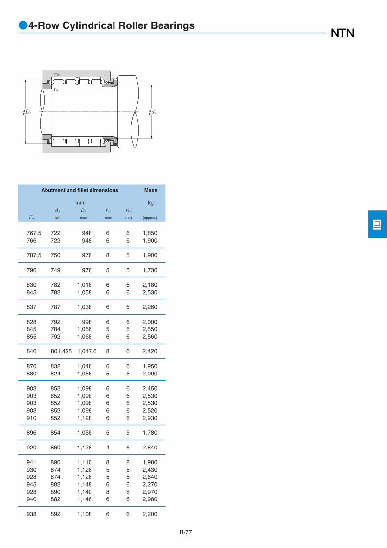
B-77
Abutment and fillet dimensions Mass
mm kgda Da ras rlas
Fw min max max max (approx.)
●4-Row Cylindrical Roller Bearings
φDa
r1a
ra
φda
767.5 722 948 6 6 1,850766 722 948 6 6 1,900
787.5 750 976 8 5 1,900
796 749 976 5 5 1,730
830 782 1,018 6 6 2,180845 782 1,058 6 6 2,530
837 787 1,038 6 6 2,260
828 792 998 6 6 2,000845 784 1,056 5 5 2,550855 792 1,068 6 6 2,560
846 801.425 1,047.6 8 6 2,420
870 832 1,048 6 6 1,950880 824 1,056 5 5 2,090
903 852 1,098 6 6 2,450903 852 1,098 6 6 2,530903 852 1,098 6 6 2,530903 852 1,098 6 6 2,520910 852 1,128 6 6 2,930
896 854 1,056 5 5 1,780
920 860 1,128 4 6 2,840
941 890 1,110 8 8 1,980930 874 1,126 5 5 2,430928 874 1,126 5 5 2,640945 882 1,148 6 6 2,270928 890 1,140 8 8 2,970940 882 1,148 6 6 2,980
938 892 1,108 6 6 2,200

B-78
●4-Row Cylindrical Roller Bearings
Boundary dimensions Basic load ratings Bearing Drawing1
dynamic static dynamic static numbers No.mm kN kgf
d D B1 C1 rs min2
rls min2
Cr Cor Cr Cor
1 Drawing details are shown in Page B-38.2 Minimal allowable dimension for chamfer dimension r or r1.
d 860~1,200mm
C1
φd
r1
B1
φD φFW
r
1,160 735 710 6 6 17,800 62,500 1,810,000 6,400,000 4R17201 F1)
1,230 895 870 7.5 7.5 24,700 88,000 2,520,000 9,000,000 4R18001 FM2)
1,280 865 850 7.5 7.5 26,200 88,500 2,670,000 9,000,000 4R18401 F
1,310 880 880 9.5 9.5 23,400 88,500 2,380,000 9,000,000 4R20001 F1)
1,360 800 800 7.5 7.5 25,000 85,000 2,550,000 8,650,000 4R20002 F1)
1,380 850 850 7.5 7.5 24,400 89,000 2,490,000 9,100,000 4R20601 F1)
1,590 1,050 1,050 7.5 7.5 36,000 133,000 3,650,000 13,600,000 4R24002 FS
920
1,000
1,030
1,200
860
900

B-79
Abutment and fillet dimensions Mass
mm kgda Da ras rlas
Fw min max max max (approx.)
●4-Row Cylindrical Roller Bearings
φDa
r1a
ra
φda
940 884 1,136 5 5 2,310
985 932 1,198 6 6 3,250
1,015 952 1,248 6 6 3,560
1,080 1,040 1,270 8 8 3,2601,090 1,032 1,328 6 6 3,530
1,124 1,062 1,348 6 6 3,800
1,295 1,232 1,558 6 6 6,220

Boundary dimensions Basic load ratings Bearing numbers Dimensionsdynamic static dynamic static
mm kN kgf mm
d D B rs min1
Cr Cor Cr Cor Fixed side Free side J K M e2
●SL Type Cylindrical Roller Bearings
B-801 Maximum allowable dimension for chamfer dimension r. 2 Allowable axial move.
d 100~280mm
140 40 1.1 194 400 19,800 41,000 SL01-4920 SL02-4920 116 125 126.5 2
150 40 1.1 202 430 20,600 44,000 SL01-4922 SL02-4922 125 134 135.5 2
165 45 1.1 226 480 23,100 49,000 SL01-4924 SL02-4924 138.5 148.5 150.5 3
180 50 1.5 262 555 26,700 56,500 SL01-4926 SL02-4926 149 160 162 4
190 50 1.5 272 595 27,700 60,500 SL01-4928 SL02-4928 159.5 170 172.5 4
190 40 1.1 235 575 23,900 58,500 SL01-4830 SL02-4830 165.5 173.5 175.5 2210 60 2 410 865 41,500 88,000 SL01-4930 SL02-4930 171.5 186 189.5 4
200 40 1.1 241 605 24,600 62,000 SL01-4832 SL02-4832 173.5 182.5 184 2220 60 2 425 935 43,500 95,000 SL01-4932 SL02-4932 185 199 203 4
215 45 1.1 265 650 27,000 66,500 SL01-4834 SL02-4834 186.5 196.5 198 3230 60 2 435 980 44,500 100,000 SL01-4934 SL02-4934 194 208 211.5 4
225 45 1.1 275 695 28,000 71,000 SL01-4836 SL02-4836 199 209 211 3250 69 2 550 1,230 56,000 125,000 SL01-4936 SL02-4936 206 222 225.5 4
240 50 1.5 315 785 32,000 80,000 SL01-4838 SL02-4838 208.5 219.5 221.5 4260 69 2 565 1,290 57,500 131,000 SL01-4938 SL02-4938 216.5 232.5 235.5 4
250 50 1.5 320 825 33,000 84,000 SL01-4840 SL02-4840 219 230 232 4280 80 2.1 665 1,500 68,000 153,000 SL01-4940 SL02-4940 232 250 253.5 5
270 50 1.5 340 905 34,500 92,500 SL01-4844 SL02-4844 240 251 253 4300 80 2.1 695 1,620 70,500 165,000 SL01-4944 SL02-4944 249.5 267.5 271 5
300 60 2 510 1,330 52,000 136,000 SL01-4848 SL02-4848 261 275 276.5 4320 80 2.1 730 1,770 74,000 181,000 SL01-4948 SL02-4948 272.5 290.5 294 5
320 60 2 535 1,450 54,500 148,000 SL01-4852 SL02-4852 283 297 300 4360 100 2.1 1,070 2,520 109,000 257,000 SL01-4952 SL02-4952 297 320 324.5 6
350 69 2 685 1,860 69,500 189,000 SL01-4856 SL02-4856 308 324 327 4380 100 2.1 1,110 2,710 114,000 277,000 SL01-4956 SL02-4956 319 342 346 6
100
110
120
130
140
150
160
170
180
190
200
220
SL01-48 type SL01-49 type(Fixed side)
SL02-48 type SL02-49 type(Free side)
B
r
r
B
r
r
φMφD φJφdφKφD φJφd
240
260
280

●SL Type Cylindrical Roller Bearings
Abutment and Mass (approx.)fillet dimensions
mm kg
da3
Da3
ras
min max max Fixed side Free side
B-813 Use J and K dimensions for bearings operating at inclined or large axial loads.
106.5 133.5 1 1.95 1.9
116.5 143.5 1 2.15 2.1
126.5 158.5 1 2.95 2.85
138 172 1.5 3.95 3.8
148 182 1.5 4.2 4.1
156.5 183.5 1 2.9 2.8159 201 2 6.65 6.45
166.5 193.5 1 3.05 2.9169 211 2 7 6.8
176.5 208.5 1 4.1 3.95179 221 2 7.35 7.1
186.5 218.5 1 4.3 4.15189 241 2 10.7 10.5
198 232 1.5 5.65 5.45199 251 2 11.2 10.9
208 242 1.5 5.9 5.7211 269 2 15.7 15.3
228 262 1.5 6.4 6.2231 289 2 17.1 16.6
249 291 2 10.2 9.9251 309 2 18.4 17.9
269 311 2 11 10.6271 349 2 32 31.2
289 341 2 16 15.6291 369 2 33.9 33.1
Fixed side Free side
ra
ra
φdaφDa
ra
ra
φDaφDa

●SL Type Cylindrical Roller Bearings
Boundary dimensions Basic load ratings Bearing numbers Dimensionsdynamic static dynamic static
mm kN kgf mm
d D B rs min1
Cr Cor Cr Cor Fixed side Free side J K M e2
B-821 Maximum allowable dimension for chamfer dimension r. 2 Allowable axial move.
d 300~440mm
380 80 2.1 805 2,160 82,000 220,000 SL01-4860 SL02-4860 330 348 351 6420 118 3 1,580 3,800 161,000 385,000 SL01-4960 SL02-4960 344 371 377 6
400 80 2.1 835 2,310 85,000 236,000 SL01-4864 SL02-4864 353 371 374 6440 118 3 1,650 4,100 168,000 415,000 SL01-4964 SL02-4964 371 398 404 6
420 80 2.1 855 2,430 87,500 248,000 SL01-4868 SL02-4868 370 388 391 6460 118 3 1,690 4,300 172,000 440,000 SL01-4968 SL02-4968 388 416 421 6
440 80 2.1 885 2,580 90,000 264,000 SL01-4872 SL02-4872 393 411 414 6480 118 3 1,730 4,500 176,000 460,000 SL01-4972 SL02-4972 406 434 439 6
480 100 2.1 1,290 3,600 132,000 370,000 SL01-4876 SL02-4876 422 444 449 6520 140 4 2,300 5,900 235,000 600,000 SL01-4976 SL02-4976 437 469 475 7
540 140 4 2,410 6,200 246,000 635,000 SL01-4980 SL02-4980 450 484 490 7
560 140 4 2,470 6,500 252,000 665,000 SL01-4984 SL02-4984 472 505 512 7
600 160 4 3,000 7,850 305,000 800,000 SL01-4988 SL02-4988 503 540 546 7
300
320
340
360
380
400
420
440
SL01-48 type SL01-49 type(Fixed side)
SL02-48 type SL02-49 type(Free side)
B
r
r
B
r
r
φMφD φJφdφKφD φJφd

●SL Type Cylindrical Roller Bearings
B-833 Use J and K dimensions for bearings operating at inclined or large axial loads.
Fixed side Free side
ra
ra
φdaφDa
ra
ra
φDaφDa
Abutment and Mass (approx.)fillet dimensions
mm kg
da3
Da3
ras
min max max Fixed side Free side
311 369 2 23 22.2313 407 2.5 53 51.9
331 389 2 24.3 23.5333 427 2.5 56 54.9
351 409 2 25.6 24.8353 447 2.5 59 57.8
371 429 2 27 26373 467 2.5 62 60.8
391 469 2 45.3 44396 504 3 92.3 90.5
416 524 3 96.4 94.6
436 544 3 101 98.6
456 584 3 139 137

Boundary dimensions Basic load ratings Bearingdynamic static dynamic static numbers
mm kN kgf
d D B C t r Cr Cor Cr Cor
●SL Type Cylindrical Roller Bearings for Sheaves
B-84
Note 1. The above are greased bearings. 2. The above are treated for rust prevention. 3. The above are non contact shielded bearings. Also, contact sealed can be applied upon request.
d 100~380mm
150 67 66 1.5 1 330 580 33,500 59,500 SL04-5020NR
170 80 79 1.8 1.5 385 695 39,000 71,000 SL04-5022NR
180 80 79 1.8 1.5 400 750 41,000 76,500 SL04-5024NR
200 95 94 1.8 1.5 535 1,000 55,000 102,000 SL04-5026NR
210 95 94 1.8 1.5 600 1,120 61,000 115,000 SL04-5028NR
225 100 99 2 1.5 690 1,290 70,500 131,000 SL04-5030NR
240 109 108 2 2 720 1,390 73,500 142,000 SL04-5032NR
260 122 121 2 2 925 1,790 94,500 182,000 SL04-5034NR
280 136 135 2 2 1,090 2,140 111,000 218,000 SL04-5036NR
290 136 135 2 2 1,120 2,230 114,000 227,000 SL04-5038NR
310 150 149 2 2 1,310 2,650 133,000 270,000 SL04-5040NR
340 160 159 2.5 2 1,640 3,300 167,000 335,000 SL04-5044NR
360 160 159 2.5 2 1,710 3,550 175,000 365,000 SL04-5048NR
400 190 189 3 2.5 2,130 4,500 217,000 460,000 SL04-5052NR
420 190 189 3 2.5 2,170 4,700 221,000 475,000 SL04-5056NR
460 218 216 3 2.5 2,670 5,850 272,000 600,000 SL04-5060NR
480 218 216 3 2.5 2,720 6,100 278,000 620,000 SL04-5064NR
520 243 241 3.5 3 3,650 8,000 370,000 815,000 SL04-5068NR
540 243 241 3.5 3 3,750 8,300 380,000 845,000 SL04-5072NR
560 243 241 3.5 3 3,800 8,750 385,000 895,000 SL04-5076NR
100
110
120
130
140
150
160
170
φJφDφE
Cƒ
C
ƒ
r
t
30˚
B
S
φd
180
190
200
220
240
260
280
300
320
340
360
380

●SL Type Cylindrical Roller Bearings for Sheaves
Dimensions Abutment and Massfillet dimensions
mm mm kgE
J (approx.) f Cf S da E1 Cf11
(approx.)
B-85
1 Cf1 deviation SL04-5020NR~SL04-5034NR:-0.1~ -0.5mmSL04-5036NR~SL04-5076NR:-0.1~ -0.7mm
118.5 156 2.5 54 6 106 180 54 4.03
131.5 176 2.5 65 7 116.5 200 65 7
141.5 188 3 65 7 126.5 210 65 7.5
158 208 3 77 8.5 136.5 230 77 11.4
167 218 3 77 8.5 146.5 245 77 12.1
178 233 3 81 9 157 260 81 14.6
191 248 3 89 9.5 167 275 89 18.2
203 270 4 99 11 177 300 99 24.6
220 290 4 110 12.5 187 320 110 32.3
226 300 4 110 12.5 197 330 110 33.7
245.5 320 4 120 14.5 207 350 120 43.5
260 356 6 130 14.5 228.5 380 130 55.5
280.5 376 6 130 14.5 248.5 400 130 59.5
315.5 416 7 154 17.5 270 445 154 90.7
325 436 7 154 17.5 290 465 154 96.2
363 480 8 176 20 310 510 176 137
376 500 8 176 20 330 530 176 144
406 544 8 194 23.5 352 580 194 194
421 564 10 194 23.5 372 600 194 203
442 584 10 194 23.5 392 620 194 212
φE1
Cƒ1
φda

●SL Type Cylindrical Roller Bearings for Sheaves
Boundary dimensions Basic load ratings Bearingdynamic static dynamic static numbers
mm kN kgf
d D B C t r Cr Cor Cr Cor
B-86
Note 1. The above are greased bearings. 2. The above are treated for rust prevention. 3. The above are non contact shielded bearings. Also, contact sealed can be applied upon request.
d 400~440mm
600 272 270 3.5 3 4,250 9,950 435,000 1,010,000 SL04-5080NR
620 272 270 3.5 3 4,350 10,300 445,000 1,050,000 SL04-5084NR
650 280 278 4.5 4 4,500 11,000 460,000 1,120,000 SL04-5088NR
400
420
440
φJφDφE
Cƒ
C
ƒ
r
t
30˚
B
S
φd

●SL Type Cylindrical Roller Bearings for Sheaves
Dimensions Abutment and Massfillet dimensions
mm mm kgE
J (approx.) f Cf S da E1 Cf11
(approx.)
B-87
1 Cf1 deviation SL04-5080NR~SL04-5088NR:-0.1~ -0.7mm
470 626 12 210 30 412 675 210 281
486 646 12 210 30 432 695 210 292
518 676 12 210 34 456 725 210 331
φE1
Cƒ1
φda

Tapered Roller bearings

●Tapered Roller Bearings
1. Type, Structure and Characteristics
Tapered roller bearings are designed such that theirconical rollers and raceways are arranged so that allelements of the roller and race way cones meet at a commonapex on the bearing axis. (Refer to Fig.1) The rollingelements perform the real rotating movement on theraceway; the synthesized force from the inner and outer ringraceways guides the rollers, pressing them to the large rib onthe inner ring. Metric and inch series are consideredstandard and both systems are widely used.
B-89
Table 1 Structure and characteristics of double row tapered roller bearings
Fig.1 Fig.2
E2α
Sub-unit dimensions
E : Cup small inside diameter, nominal
α : Bearing contact angle, nominal
The inner ring, rollers and cage can be separated as aunit, or the CONE, from the outer ring, or the CUP. The cupand cone are called sub-units. Sub-unit dimensions for thenominal cup small inside diameter and bearing contactangle, as shown in Fig. 2, are standardized by ISO andABMA and are compatible between sub-units. Double rowand four row bearings are available in addition to single rowbearings. Models and characteristics are shown in Tables 1and 2.
Model Drawing Nominalnumber Characteristics
¡These bearings are designed with one double row outer ring and two pairs of inner rings with rollers. Bearings are adjusted so that their internal clearance becomes the specified value, the parts which have the same serial numbers should be assembled according to the assembly codes.
¡These bearings support radial and axial loads. Since the cone pressure apex is wide, bearings are suitable where moment loads are applied.
¡These bearings have the same function as the back-to-back duplex arrangement of single row bearings.
¡This bearing model has a larger and steeper contact angle than the double row with vertex of contact angles outside the bearing. These bearings are used when the axial load is large.
¡Since these bearings are adjusted so that the internal clearance is a specified value (like the double row with vertex of contact angles outside of bearing) the parts which have the same serial numbers should be assembled according to the assembly codes.
¡ These bearings are designed with one double row inner ring with rollers and two pairs of outer rings and an outer ring spacer.
¡ These bearings accept the radial and axial loads. Since the cone pressure apex is short, bearings are not suitable when the moment is applied.
¡Since these bearings are adjusted so that the internal clearance is the specified value (like the double row with vertex of contact angles outside of bearing) the parts which have the same serial numbers should be assembled according to the assembly codes.
¡ This bearing model has a larger and steeper contact angle than the double row with vertex of contact angles inside the bearing. These bearings are used when the axial load is large or only axials are applied.
¡ Models without an outer ring spacer and with a key groove or notch on the inner ring (refer to the drawing) are also available. Consult NTN Engineering about this bearing's fit.
¡ These bearings may be pressurized by using a spring between the housing shoulder and outer ring end.
413XXX423XXX430XXX432XXX
CRI
CRI
3230XX3231XX
CRD
CRD
Double row with vertex of contact steep angles inside of the bearing
Double row with vertex of contact angles inside of the bearing
Double row with vertex of contact steep angles outside of the bearing
Double row with vertex of contact angles outside of the bearing

●Tapered Roller Bearings
B-90
2. Dimensional Accuracy/Rotation Accuracy
Metric system bearings ⋯⋯⋯Table 3.4 (Page A-14)Inch system bearings ⋯⋯⋯⋯Table 3.5 (Page A-16)
3. Recommended Fitting
Metric system bearings ⋯⋯⋯Table 4.2 (Page A-24)Inch system bearings ⋯⋯⋯⋯Table 4.5, 4.6 (Page A-27)
4. Bearing Internal Clearance
Metric system bearings ⋯⋯⋯Table 5.7 (Page A-32)Inch system bearings ⋯⋯⋯⋯Table 5.9 (Page A-34)
5. General Operating Cautions
Slippage between the balls and raceways may occurwhen bearings are operated under small loads, or when theratio between axial and radial loads of the duplexedbearings exceeds the value “e,” and may cause smearing.This is most apparent when using large size tapered rollerbearings due to the large cage mass. Please consult NTNEngineering for further details.
Table 2 Structure and characteristics of the four row tapered roller bearings
Model Drawing Nominalnumbers
Characteristics
¡These bearings are designed with two double row inner rings with rollers, one double row outer ring, two single outer ring and outer ring spacer/inner ring spacer. Bearings are adjusted so that their internal clearance becomes the specified value, the parts which have the same serial numbers should be assembled according to the assembly codes.
¡The bearing is mainly used for the roll neck of rolling mill, and designed so as to become the maximum rating load for the allowable space in the roll neck part.
¡The bearing uses the clearance-fit to make assemble and disassembley easier. For this purpose, bearings are designed with a helical groove on the inner ring bore to prevent wearing of the inner ring bore when creep occurs and uses the carbonized steel to prevent cracks on inner ring and improve the shock resistance.
¡Please consult with NTN Engineering for fitting and bearing internal clearance.
¡Bearings are designed with oil seals on both side of the bearing which is the same as the four row tapered roller bearings.
¡Please consult with NTN Engineering for fitting and bearing internal clearance.
6259XX6230XX6231XX
CRO
CRO…LL
Four row tapered roller bearing
Four row tapered rollerbearing enclosed type

●Tapered Roller Bearings
B-91
Inch system sizes: Tapered Roller Bearings (Single row・Double row) index
Bearing number ABMA Page
CONE / CUP Type
8573/8520 TS B-109
8573/8520D+A TDO B-140
8575/8520 TS B-109
8575/8520D+A TDO B-140
8578/8520 TS B-111
8578/8520D+A TDO B-140
29875/29820 TS B-111
29875/29820D+A TDO B-142
29880/29820 TS B-111
29880/29820D+A TDO B-142
38880/38820 TS B-111
38885/38820 TS B-111
67983/67920 TS B-107
67983/67920D+A TDO B-138
67985/67920 TS B-107
67985/67920D+A TDO B-140
67989/67920 TS B-109
67989/67920D+A TDO B-140
80170/80217 TS B-117
80176/80217 TS B-117
80180/80217 TS B-117
80385/80325 TS B-117
80780/80720 TS B-121
87737/87111 TS B-107
87737/87112D+A TDO B-138
87750/87111 TS B-107
87750/87112D+A TDO B-138
87762/87111 TS B-107
87762/87112D+A TDO B-138
93708/93125 TS B-107
93750/93125 TS B-107
93750/93127D+A TDO B-138
93787/93125 TS B-107
93787/93727D+A TDO B-138
93800/93125 TS B-107
93800/93127D+A TDO B-138
93800D/93125+A TDI B-161
93825/93125 TS B-109
93825/93127D+A TDO B-140
94649/94113 TS B-105
94649/94114D+A TDO B-138
94687/94113 TS B-105
94687/94114D+A TDO B-138
94700/94113 TS B-107
94700/94114D+A TDO B-138
94706D/94113+A TDI B-161
96900/96140 TS B-109
96900/96140D+A TDO B-140
96925/96140 TS B-109
96925/96140D+A TDO B-140
EE113089/113170 TS B-109
EE113091/113170 TS B-109
EE113091/113171D+A TDO B-140
EE114080/114160 TS B-107
Bearing number ABMA Page
CONE / CUP Type
EE114080/114161D+A TDO B-138
EE117063/117148 TS B-105
EE126096D/126150+A TDI B-161
EE126097/126150 TS B-111
EE126097/126151D+A TDO B-142
EE126098/126151D+A TDO B-142
EE126098/126150 TS B-111
EE127095/127135 TS B-111
EE127095/127136D+A TDO B-140
EE127097D/127135+A TDI B-161
EE128111/128160 TS B-113
EE128111/128160D+A TDO B-142
EE128112/128160 TS B-113
EE129120X/129172 TS B-113
EE129120X/129120D+A TDO B-144
EE130902/131400 TS B-109
EE130902/131401D+A TDO B-140
EE134100/134143 TS B-111
EE134100/134144D+A TDO B-142
EE134102/134143 TS B-111
EE134102/134144D+A TDO B-142
EE135111D/135155+A TDI B-163
HH144642/HH144614 TS B-107
EE147112/147198D+A TDO B-144
EE161300/161900 TS B-115
EE161300/161901D+A TDO B-144
EE161363/161900 TS B-115
EE161363/161901D+A TDO B-144
EE161400/161850 TS B-115
EE161400/161900 TS B-115
EE161400/161901D+A TDO B-144
L163149/L163110 TS B-115
L163149/L163110D+A TDO B-144
L163149D/L163110+A TDI B-163
EE170950/171450 TS B-111
EE170950/171451D+A TDO B-142
EE170975/171450 TS B-111
EE170975/171451D+A TDO B-140
EE170975D/171450+A TDI B-161
EE192150/192200 TS B-115
EE192150/192201D+A TDO B-146
EE219068/219117 TS B-105
EE219068/219122 TS B-105
EE221025D/221575+A TDI B-161
EE221026/221575 TS B-111
EE221026/221576D+A TD0 B-142
EE222070/222127D+A TDO B-138
EE231400/231975 TS B-115
EE231400/231976D+A TDO B-146
EE231401D/231975+A TDI B-163
EE231462/231975 TS B-115
EE231462/231976D+A TDO B-146
HH231637/HH231615 TS B-105
HH231649/HH231610 TS B-105
Bearing number ABMA Page
CONE / CUP Type
HH231649/HH231615 TS B-105
HH234031/HH234010 TS B-105
HH234031/HH234011D+A TDO B-138
HH234048/HH234010 TS B-105
HH234048/HH234011D+A TDO B-138
EE234156/234213D+A TDO B-146
EE234156/234215 TS B-117
EE234156/234216D+A TDO B-146
EE234160/234213D+A TDO B-146
EE234160/234215 TS B-117
HM237532/HM237510 TS B-105
HM237532/HM237510D+A TDO B-138
HM237535/HM237510 TS B-105
HM237535/HM237510D+A TDO B-138
HM237542/HM237510 TS B-105
HM237542/HM237510D+A TDO B-138
HM237545/HM237510 TS B-107
HM237545/HM237513 TS B-107
HM237545/HM237510D+A TDO B-138
HM237546D/HM237510+A TDI B-161
H238140/H238110 TS B-105
H238148/H238110 TS B-105
H239640/H239610 TS B-107
H239640/H239612D+A TDO B-138
H239649/H239610 TS B-107
H239649/H239612 TS B-107
H239649/H239612D+A TDO B-138
H239649D/H239610+A TDI B-161
LM241149/LM241110 TS B-107
LM241149/LM241110D+A TDO B-138
M241547/M241510 TS B-107
M241543/M241510 TS B-107
M241543/M241510D+A TDO B-138
M241547/M241510D+A TDO B-138
M241549/M241510 TS B-107
M241549/M241510D+A TDO B-138
EE241701/242375 TS B-117
EE241701/242377D+A TDO B-146
H242649/H242610 TS B-107
H242649/H242610D+A TDO B-140
H242649D/H242610+A TDI B-161
EE243190/243250 TS B-119
EE243190/243251D+A TDO B-146
EE243192/243250 TS B-119
EE243192/243251D+A TDO B-148
EE243196/243250 TS B-119
EE243196/243251D+A TDO B-148
EE244180/244235 TS B-119
EE244180/244236D+A TDO B-146
M244249/M244210 TS B-109
M244249/M244210D+A TDO B-140
M244249D/M244210+A TDI B-161
H244849D/H244810+A TDI B-161
M246942/M246910 TS B-109

B-92
●Tapered Roller Bearings
Inch system sizes: Tapered Roller Bearings (Single row・Double row) index
Bearing number ABMA Page
CONE / CUP Type
M246949/M246910 TS B-109
H247535/H247510 TS B-107
H247535/H247510D+A TDO B-138
H247549/H247510 TS B-109
H247549/H247510D+A TDO B-140
LM247748D/LM247710+A TDI B-161
H249148/H249111D+A TDO B-140
M249732/M249710 TS B-109
M249732/M249710D+A TDO B-140
M249734/M249710 TS B-109
M249734/M249710D+A TDO B-140
M249736/M249710 TS B-109
M249736/M249710D+A TDO B-140
M249748D/M249710+A TDI B-161
M249749/M249710 TS B-111
M249749/M249710D+A TDO B-142
HH249749/HH249910D+A TDO B-142
HH249949/HH249910 TS B-111
HH249949D/HH249910+A TDI B-161
M252337/M252310 TS B-111
HM252343/HM252310 TS B-111
HM252343/HM252310D+A TDO B-142
HM252344/HM252310D+A TDO B-142
M252349D/M252310+A TDI B-161
HM252348/HM252310 TS B-111
HM252348/HM252310D+A TDO B-142
HM252349/HM252310D+A TDO B-142
M252330/M252310 TS B-109
M252349/M252310 TS B-113
HH255149D/HH255110+A TDI B-161
M255449/M255410 TS B-113
M255449/M255410D+A TDO B-144
M255449D/M255410A+A TDI B-163
HM256849/HM256810 TS B-113
HM256849/HM256810D+A TDO B-144
HM256849D/HM256810+A TDI B-163
M257149D/M257110+A TDI B-163
M257248D/M257210+A TDI B-163
HH258248/HH258210 TS B-113
HH258248/HH258210D+A TDO B-144
LM258648D/LM258610+A TDI B-163
HM259048/HM259010 TS B-115
HM259049/HM259010D+A TDO B-144
HM259049D/HM259010+A TDI B-163
HM261049/HM261010 TS B-115
HM261049/HM261010D+A TDO B-144
HM261049D/HM261010+A TDI B-163
M262449D/M262410+A TDI B-163
HM262749/HM262710 TS B-115
HM262749/HM262710D+A TDO B-144
HM262749D/HM262710+A TDI B-163
HM262748/HM262710 TS B-115
LM263149D/LM263110+A TDI B-163
M263349D/M263310+A TDI B-163
Bearing number ABMA Page
CONE / CUP Type
HM265049/HM265010D+A TDO B-146
HM265049D/HM265010+A TDI B-163
HM265049/HM265010 TS B-115
HM266447/HM266410 TS B-117
HM266448/HM266410 TS B-117
HM266449/HM266410 TS B-117
HM266449/HM266410D+A TDO B-146
HM266446/HM266410 TS B-117
HM266446/HM266410D+A TDO B-146
HM266448/HM266410D+A TDO B-146
HM266449D/HM266410+A TDI B-163
M268730/M268710 TS B-117
HM268730/HM268710D+A TDO B-146
M268749/M268710 TS B-117
M268749/M268710D+A TDO B-146
M268749D/M268710+A TDI B-165
M270749/M270710 TS B-117
M270749/M270710D+A TDO B-146
M270749D/M270710+A TDI B-165
LM272235/LM272210 TS B-119
LM272249/LM272210 TS B-119
LM272249/LM272210D+A TDO B-146
LM272249D/LM272210+A TDI B-165
M272647D/M272610+A TDI B-165
M272749/M272710 TS B-119
M272749/M272710D+A TDO B-146
M272749D/M272710+A TDI B-165
M274149/M274110 TS B-119
M274149D/M274110+A TDI B-165
LM274449D/LM274410+A TDI B-165
EE275095/275155 TS B-111
EE275095/275156D+A TDO B-140
EE275100/275155 TS B-111
EE275100/275156D+A TDO B-142
EE275105/275155 TS B-111
EE275105/275156D+A TDO B-142
EE275108/275155 TS B-113
EE275108/275156D+A TDO B-142
EE275109D/275155+A TDI B-161
M275349D/M275310+A TDI B-165
M276449/M276410 TS B-119
M276449/M276410D+A TDO B-148
M276449D/M276410+A TDI B-165
M276448D/M276410+A TDI B-165
M278749/M278710 TS B-119
M278749/M278710D+A TDO B-148
M278749D/M278710+A TDI B-165
M280049D/M280010+A TDI B-167
M280349D/M280310+A TDI B-167
EE280626/281200 TS B-105
M281049D/M281010+A TDI B-167
L281148/L281110 TS B-121
L281148/L281110D+A TDO B-148
L281149D/L281110+A TDI B-167
Bearing number ABMA Page
CONE / CUP Type
M281649D/M281610+A TDI B-167
LM281849D/LM281810+A TDI B-167
LM282549D/LM282510+A TDI B-167
LM283649/LM283610 TS B-121
LM283649D/LM283649+A TDI B-167
M284148D/M284111+A TDI B-167
M284249D/M284210+A TDI B-167
LM286249D/LM286210+A TDI B-167
LM287649D/LM287610+A TDI B-167
LM287849D/LM287810+A TDI B-167
EE291175/291750 TS B-113
EE291175/291751D+A TDO B-144
EE291200D/291750+A TDI B-161
EE291201/291750 TS B-113
EE291201/291751D+A TDO B-144
EE291250/291750 TS B-115
EE291250/291751D+A TDO B-144
EE295102/295193 TS B-111
EE295102/295192D+A TDO B-142
EE295110/295193 TS B-113
EE295110/295192D+A TDO B-142
EE329119D/329172+A TDI B-163
EE333137/333197 TS B-115
EE333137/333203D+A TDO B-144
EE333140/333197 TS B-115
EE333140/333203D+A TDO B-146
M348449/M348410 TS B-111
M349549/M349510 TS B-111
EE350701/351687 TS B-107
EE350750/351687 TS B-107
L357049/L357010 TS B-113
L357049/L357010D+A TDO B-144
LM361649/LM361610 TS B-115
LL365340/LL365310D+A TDO B-146
LL365348/LL365310 TS B-117
LM377449/LM377410 TS B-119
LM377449/LM377410D+A TDO B-148
LM377449D/LM377410+A TDI B-165
EE380080/380190 TS B-107
EE380081/380190 TS B-107
EE420751/421437 TS B-107
EE420751/421451D+A TDO B-138
EE420750D/421437+A TDI B-161
EE420800D/421437+A TDI B-161
EE420801/421437 TS B-107
EE420801/421451D+A TDO B-138
EE426200/426330 TS B-119
EE426200/426331D+A TDO B-148
EE430900/431575 TS B-109
EE430900/431576D+A TDO B-140
EE435102/435165 TS B-111
EE435102/435165D+A TDO B-142
HH437549/HH437510 TS B-105
LM446349/LM446310 TS B-109

B-93
●Tapered Roller Bearings
Inch system sizes: Tapered Roller Bearings (Single row・Double row) index
Bearing number ABMA Page
CONE / CUP Type
LM446349/LM446310D+A TDO B-140
EE450601/451212 TS B-105
EE450601/451215D+A TDO B-138
450900D/451212 TDI B-161
LM451345/LM451310 TS B-111
LM451345/LM451310D+A TDO B-142
LM451349/LM451310 TS B-111
LM451349/LM451310D+A TDO B-142
LM451349D/LM451310+A TDI B-161
L467549/L467510 TS B-117
L476549/L476510 TS B-119
L476549/L476510D+A TDO B-148
LL481448/LL481411 TS B-121
EE526130/526190 TS B-115
EE526130/526191D+A TDO B-144
EE529091D/529157+A TDI B-161
EE542220/542290 TS B-119
EE542220/542291D+A TDO B-148
HM542948/HM542911 TS B-107
543085/543114 TS B-109
543085/543115D+A TDO B-140
544090/544118 TS B-109
544091/544118 TS B-109
545112/545141 TS B-113
545112/545142D+A TDO B-144
LM545849/LM545810 TS B-109
EE547341D/547480+A TDI B-167
L555233/L555210 TS B-113
L555233/L555210D+A TDO B-142
L555249/L555210 TS B-113
L555249/L555210D+A TDO B-144
LL562749/LL562710 TS B-115
LM565943/LM565910 TS B-115
LM565949/LM565910 TS B-117
LM565949/LM565912 TS B-117
LL566848/LL566810 TS B-117
LM567949/LM567910 TS B-117
L570649/L570610 TS B-117
EE571703/572650 TS B-117
EE571703/572651D+A TDO B-146
LL575343/LL575310 TS B-119
LL575349/LL575310 TS B-119
EE626210/626321D+A TDO B-148
EE640192/640260 TS B-119
EE640192/640261D+A TDO B-148
EE649240/649310 TS B-121
EE649240/649311D+A TDO B-148
EE649241D/649310+A TDI B-167
LM654642/LM654610 TS B-113
LM654642/LM654610D+A TDO B-142
LM654648D/LM654610+A TDI B-163
LM654649/LM654610 TS B-113
LM654649/LM654610D+A TDO B-144
EE655270/655345 TS B-121
Bearing number ABMA Page
CONE / CUP Type
EE655271D/655345+A TDI B-167
LM665949/LM665910 TS B-117
LM665949/LM665910D+A TDO B-146
M667935/M667911 TS B-117
M667947D/M667910+A TDI B-165
M667948/M667910 TS B-117
EE671801/672873 TS B-119
EE671801/672875D+A TDO B-146
680235/680270 TS B-121
LL687949/LL687910 TS B-121
LL687949/LL687910D+A TDO B-148
EE722110/722185 TS B-113
EE722110/722186D+A TDO B-142
EE722115/722185 TS B-113
EE722115/722186D+A TDO B-144
EE724120/724195 TS B-113
EE724120/724196D+A TDO B-142
LM742745/LM742710 TS B-109
LM742745/LM742710D+A TDO B-140
LM742747/LM742710 TS B-109
LM742749/LM742710 TS B-109
LM742749/LM742710D+A TDO B-140
LM742749D/LM742710+A TDI B-161
EE743240/743320 TS B-121
EE743240/743321D+A TDO B-148
HM746646/HM746610 TS B-109
HM746646/HM746610D+A TDO B-140
EE752305/752380 TS B-121
EE755280/755360 TS B-121
EE755280/755361D+A TDO B-148
EE755281D/755360+A TDI B-167
EE755285/755360 TS B-121
EE755285/755361D+A TDO B-148
LM757049/LM757010 TS B-113
M757449D/M757410+A TDI B-163
LM761649D/LM761610+A TDI B-163
EE763330/763410 TS B-121
LM763449D/LM763410+A TDI B-163
LM767745D/LM767710+A TDI B-165
LM767749D/LM767710+A TDI B-165
LM769349D/LM769310+A TDI B-165
L770847D/L770810+A TDI B-165
L770849D/L770810+A TDI B-165
LM770949/LM770910 TS B-119
LL771948/LL771911 TS B-119
LM772748/LM772710 TS B-119
LM772748/LM772710D+A TDO B-148
LM772749D/LM772710+A TDI B-165
EE776420/776520 TS B-121
EE776430/776520 TS B-121
LL778149/LL778110 TS B-119
LM778549D/LM778510+A TDI B-165
LL788345/LL788310 TS B-121
LL788349/LL788310 TS B-121
Bearing number ABMA Page
CONE / CUP Type
EE790114/790221 TS B-113
EE790120/790221 TS B-115
EE833160X/833232 TS B-117
EE833160XD/833232+A TDO B-165
HH840249/HH840210 TS B-107
EE843220/843290 TS B-119
EE843220/843291D+A TDO B-148
EE843220D/843290+A TDI B-165
H852849/H852810 TS B-113
L853049/L853010 TS B-113
L860048/L860010 TS B-115
L860049/L860010 TS B-115
L865547/L865512 TS B-115
LM869448/LM869410 TS B-117
LM869448/LM869410D+A TDO B-146
LM869449D/LM869410+A TDI B-165
L879946/L879910 TS B-121
L879947/L879910 TS B-121
LL889049/LL889010 TS B-121
LL889049/LL889010D+A TDO B-148
EE911600/912400 TS B-117
EE911600/912401D+A TDO B-146
EE923095/923175 TS B-111
EE923095/923176D+A TDO B-140
HH926744/HH926710 TS B-105
HH926744/HH926716 TS B-105
HH926749/HH926710 TS B-105
HH932132/HH932110 TS B-105
HH932145/HH932110 TS B-105
HH932145/HH932115 TS B-105
H936340/H936310 TS B-105
H936340/H936316 TS B-105
H936349/H936310 TS B-105
EE941205/941950 TS B-113
HH949549/HH949510 TS B-109
HH949549/HH949510D+A TDO B-140
HH953749/HH953710 TS B-111
HH953749/HH953710D+A TDO B-142
LM961548/LM961511D+A TDO B-144
LM961548/LM961511 TS B-115
H961649/H961610 TS B-115
H961649/H961610D+A TDO B-144
EE971354/972100 TS B-115
EE971354/972102D+A TDO B-144

B-94
●Tapered Roller Bearings
Inch system sizes: Tapered Roller Bearings (Four Row) index
Bearing number ABMA Page
CONE / CUP Type
T-8576D/8520/8520D TQO B-185
9974D/9920/9920D TQO B-183
T-46791D/46720/46721D TQO B-181
T-48290D/48220/48220D TQO B-181
T-48393D/48320/48320D TQO B-181
T-48680D/48620/48620D TQO B-181
67791D/67720/67721D TQO B-183
T-67885D/67820/67820D TQO B-183
T-67986D/67920/67920D TQO B-183
81576D/81962/81963D TQO B-181
82681D/82620/82620D TQO B-183
EE126096D/126150/126151D TQO B-185
EE127097D/127137/127137D TQO B-185
EE132082D/132125/132126D TQO B-183
EE134102D/134143/134144D TQO B-185
EE135111D/135155/135156D TQO B-187
L163149D/L163110/L163110D TQO B-191
EE171000D/171450/171451D TQO B-185
EE181455D/182350/182351D TQO B-191
EE221027D/221575/221576D TQO B-185
M224749D/M224710/M224710D TQO B-181
T-M231649D/M231610/M231610D TQO B-181
EE234161D/234215/234216D TQO B-191
M238849D/M238810/M238810D TQO B-183
M240648D/M240611/M240611D TQO B-183
M241538D/M241510/M241510D TQO B-183
EE244181D/244235/244236D TQO B-193
T-M244249D/M244210/M244210D TQO B-185
LM247748D/LM247710/LM247710D TQO B-185
T-M249748D/M249710/M249710D TQO B-185
T-M252349D/M252310/M252310D TQO B-187
HM252349D/HM252310/HM252310D TQO B-185
M255449D/M255410/M255410D TQO B-187
HM256849D/HM256810/HM256810DG2 TQO B-187
M257149D/M257110/M257110D TQO B-187
Bearing number ABMA Page
CONE / CUP Type
M257248D/M257210/M257210D TQO B-189
LM258649D/LM258610/LM258610D TQO B-189
T-HM259049D/HM259010/HM259010D TQO B-189
HM261049D/HM261010/HM261010DA TQO B-189
M262449D/M262410/M262410DG2 TQO B-189
T-HM262749D/HM262710/HM262710DG2 TQO B-189
LM263149D/LM263110/LM263110D TQO B-191
M263349D/M263310/M263310D TQO B-191
HM265049D/HM265010/HM265010DG2 TQO B-191
HM266449D/HM266410/HM266410DG2 TQO B-191
M268749D/M268710/M268710DG2 TQO B-193
M270749D/M270710/M270710DG2 TQO B-193
LM272249D/LM272210/LM272210DG2 TQO B-193
M274149D/M274110/M274110DG2 TQO B-195
LM274449D/LM274410/LM274410D TQO B-195
EE275106D/275155/275156D TQO B-185
EE275109D/275160/275161D TQO B-187
M275349D/M275310/M275310DG2 TQO B-195
M276449D/M276410/M276410DG2 TQO B-195
M278749D/M278710/M278710DG2 TQO B-195
LM278849D/LM278810/LM278810D TQO B-195
M280049D/M280010/M280010DG2 TQO B-197
M280349D/M280310/M280310DG2 TQO B-197
EE280700D/281200/281201D TQO B-183
L281149D/L281110/L281110DG2 TQO B-197
M281649D/M281610/M281610DG2 TQO B-197
LM281849D/LM281810/LM281810DG2 TQO B-197
M282249D/M282210/M282210D TQO B-197
M283449D/M283410/M283410D TQO B-199
LM283649D/LM283610/LM283610DG2 TQO B-199
M284148D/M284111/M284110DG2 TQO B-199
M284249D/M284210/M284210DG2 TQO B-199
M285848D/M285810/M285810D TQO B-199
LM286249D/LM286210/LM286210DG2 TQO B-199
LM287649D/LM287610/LM287610DG2 TQO B-199
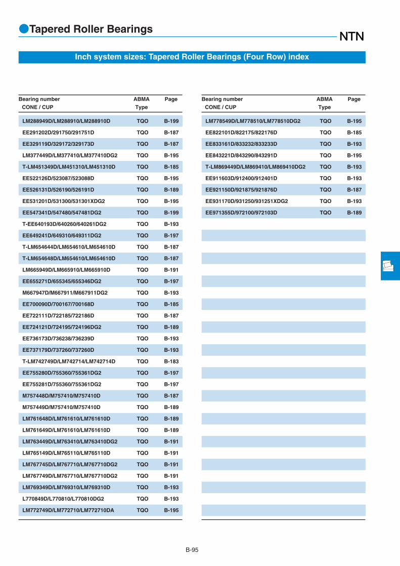
B-95
●Tapered Roller Bearings
Inch system sizes: Tapered Roller Bearings (Four Row) index
Bearing number ABMA Page
CONE / CUP Type
LM288949D/LM288910/LM288910D TQO B-199
EE291202D/291750/291751D TQO B-187
EE329119D/329172/329173D TQO B-187
LM377449D/LM377410/LM377410DG2 TQO B-195
T-LM451349D/LM451310/LM451310D TQO B-185
EE522126D/523087/523088D TQO B-195
EE526131D/526190/526191D TQO B-189
EE531201D/531300/531301XDG2 TQO B-195
EE547341D/547480/547481DG2 TQO B-199
T-EE640193D/640260/640261DG2 TQO B-193
EE649241D/649310/649311DG2 TQO B-197
T-LM654644D/LM654610/LM654610D TQO B-187
T-LM654648D/LM654610/LM654610D TQO B-187
LM665949D/LM665910/LM665910D TQO B-191
EE655271D/655345/655346DG2 TQO B-197
M667947D/M667911/M667911DG2 TQO B-193
EE700090D/700167/700168D TQO B-185
EE722111D/722185/722186D TQO B-187
EE724121D/724195/724196DG2 TQO B-189
EE736173D/736238/736239D TQO B-193
EE737179D/737260/737260D TQO B-193
T-LM742749D/LM742714/LM742714D TQO B-183
EE755280D/755360/755361DG2 TQO B-197
EE755281D/755360/755361DG2 TQO B-197
M757448D/M757410/M757410D TQO B-187
M757449D/M757410/M757410D TQO B-189
LM761648D/LM761610/LM761610D TQO B-189
LM761649D/LM761610/LM761610D TQO B-189
LM763449D/LM763410/LM763410DG2 TQO B-191
LM765149D/LM765110/LM765110D TQO B-191
LM767745D/LM767710/LM767710DG2 TQO B-191
LM767749D/LM767710/LM767710DG2 TQO B-191
LM769349D/LM769310/LM769310D TQO B-193
L770849D/L770810/L770810DG2 TQO B-193
LM772749D/LM772710/LM772710DA TQO B-195
Bearing number ABMA Page
CONE / CUP Type
LM778549D/LM778510/LM778510DG2 TQO B-195
EE822101D/822175/822176D TQO B-185
EE833161D/833232/833233D TQO B-193
EE843221D/843290/843291D TQO B-195
T-LM869449D/LM869410/LM869410DG2 TQO B-193
EE911603D/912400/912401D TQO B-193
EE921150D/921875/921876D TQO B-187
EE931170D/931250/931251XDG2 TQO B-193
EE971355D/972100/972103D TQO B-189

B-96
●Single Row Tapered Roller Bearings
Boundary dimensions Basic load ratings Bearingdynamic static dynamic static numbers
mm kN kgf
d D T B C rs min1
rls min1
Cr Cor Cr Cor
1 Minimal allowable dimension for chamfer dimension r or r1. 2 This bearing does not incorporate the subunit dimensions.
d 100~120mm
T
C
φD
B
r1
φd
r
a
Metric system sizes
140 25 25 20 1.5 1.5 121 206 12,300 21,000 32920XU140 25 24 20 1.5 1.5 97.5 162 9,950 16,500 329202
150 32 32 24 2 1.5 170 281 17,300 28,600 32020XU150 39 39 32.5 2 1.5 224 390 22,800 39,500 33020U180 37 34 29 3 2.5 258 335 26,300 34,500 30220U180 49 46 39 3 2.5 330 465 33,500 47,500 32220U215 51.5 47 39 4 3 410 500 41,500 51,000 30320U215 51.5 47 39 3 3 345 400 35,000 40,500 303202
215 56.5 51 35 4 3 355 435 36,000 44,000 31320XU215 77.5 73 60 4 3 570 770 58,500 78,500 32320U
145 25 25 20 1.5 1.5 126 219 12,800 22,400 32921XA2
160 35 35 26 2.5 2 201 335 20,500 34,000 32021XU160 43 43 34 2.5 2 245 420 25,000 43,000 33021U190 39 36 30 3 2.5 287 380 29,300 38,500 30221U190 53 50 43 3 2.5 380 540 38,500 55,500 32221U225 53.5 49 41 4 3 435 535 44,500 54,500 30321U225 53.5 49 41 3 3 365 420 37,000 43,000 303212
225 58 53 36 4 3 380 470 39,000 47,500 31321XU225 81.5 77 63 4 3 610 825 62,500 84,500 32321U
150 25 25 20 1.5 1.5 127 226 13,000 23,100 32922XA2
170 38 38 29 2.5 2 236 390 24,000 39,500 32022XU170 47 47 37 2.5 2 288 500 29,400 51,000 33022U200 41 38 32 3 2.5 325 435 33,000 44,000 30222U200 56 53 46 3 2.5 420 605 43,000 62,000 32222U240 54.5 50 42 4 3 480 590 49,000 60,000 30322U240 54.5 50 42 3 3 400 465 40,500 47,000 303222
240 63 57 38 4 3 430 535 44,000 54,500 31322XU240 84.5 80 65 4 3 705 970 72,000 98,500 32322U240 84.5 80 65 3 3 620 830 63,500 84,500 323222
165 29 29 23 1.5 1.5 162 294 16,500 30,000 32924XU165 29 27 23 1.5 1.5 118 205 12,000 20,900 329242
180 38 38 29 2.5 2 245 420 25,000 43,000 32024XU215 43.5 40 34 3 2.5 345 470 35,500 48,000 30224U215 61.5 58 50 3 2.5 460 680 47,000 69,500 32224U260 59.5 55 46 4 3 560 695 57,000 71,000 30324U260 59.5 55 46 3 3 465 550 47,500 56,000 303242
100
105
110
120

B-97
●Single Row Tapered Roller Bearings
1 0 0.4 Y2
Fa
FrX Y X Y
≦eFa
Fr>e
Pr=XFr+YFa
Equivalent bearing loaddynamic
Por=0.5Fr+YoFa
When Por<Fr use Por=Fr
For values of e, Y2 and Yosee the table below.
static
Sa
r1a
Sb
ra
φda φDbφDa φdb
Abutment and fillet dimensions Load Constant Axial Masscenter load factors
mm mm kg
da db Da Db Sa Sb ras r1as
min max max min min min min max max a e Y2 Yo (approx.)
108.5 107.5 131.5 127.5 135.5 4 5 1.5 1.5 24.5 0.33 1.82 1.00 1.14108.5 107.5 131.5 127.5 135.5 4 5 1.5 1.5 25 0.35 1.73 0.95 1.08110 109 141.5 134 144 6 8 2 1.5 32.5 0.46 1.31 0.72 1.91110 108 141.5 135 143 7 6.5 2 1.5 29.5 0.29 2.09 1.15 2.37114 116 168 157 168 5 8 2.5 2 36 0.42 1.43 0.79 3.78114 114 168 154 171 5 10 2.5 2 41.5 0.42 1.43 0.79 5.12118 127 201 184 200 5 12.5 3 2.5 41.5 0.35 1.74 0.96 8.56118 127 201 184 200 5 12.5 3 2.5 42 0.35 1.73 0.95 7.72118 121 201 168 202 7 21.5 3 2.5 69 0.83 0.73 0.40 8.67118 121 201 177 200 5 17.5 3 2.5 53 0.35 1.74 0.96 12.7
113.5 113.5 136.5 131.5 140.5 5 5 1.5 1.5 25 0.34 1.76 0.97 1.2117 116 150 143 154 6 9 2 2 34.5 0.44 1.35 0.74 2.42117 116 150 145 153 7 9 2 2 31 0.28 2.12 1.17 3119 122 178 165 178 6 9 2.5 2 38 0.42 1.43 0.79 4.39119 119 178 161 180 6 10 2.5 2 44 0.42 1.43 0.79 6.25123 132 211 193 209 6 12.5 3 2.5 43.5 0.35 1.74 0.96 9.79123 132 211 193 209 6 12.5 3 2.5 43.5 0.35 1.73 0.95 8.93123 126 211 176 211 7 22 3 2.5 71.5 0.83 0.73 0.40 9.68123 128 211 185 209 6 18.5 3 2.5 55 0.35 1.74 0.96 14.5
118.5 117.5 141.5 137 145.5 5 5 1.5 1.5 26.5 0.36 1.69 0.93 1.23122 122 160 152 163 7 9 2 2 36.5 0.43 1.39 0.77 3.07122 121 160 152 161 7 10 2 2 33.5 0.29 2.09 1.15 3.8124 129 188 174 188 6 9 2.5 2 40 0.42 1.43 0.79 5.18124 126 188 170 190 6 10 2.5 2 47 0.42 1.43 0.79 7.43128 141 226 206 222 6 12.5 3 2.5 45.5 0.35 1.74 0.96 11.4128 141 226 206 222 6 12.5 3 2.5 44 0.35 1.73 0.95 10.5128 135 226 188 224 7 25 3 2.5 76 0.83 0.73 0.40 11.9128 135 226 198 222 6 19.5 3 2.5 57.5 0.35 1.74 0.96 18128 135 226 198 222 6.5 19.5 3 2.5 56 0.35 1.73 0.95 16.9
128.5 128.5 156.5 150 160 6 6 1.5 1.5 29.5 0.35 1.72 0.95 1.77128.5 130.5 156.5 147.5 159.5 6 6 1.5 1.5 31 0.37 1.60 0.88 1.63132 131 170 161 173 7 9 2 2 39 0.46 1.31 0.72 3.25134 140 203 187 203 6 9.5 2.5 2 44 0.44 1.38 0.76 6.23134 136 203 181 204 6 11.5 2.5 2 51.5 0.44 1.38 0.76 9.08138 152 246 221 239 6 13.5 3 2.5 49 0.35 1.74 0.96 14.2138 152 246 221 239 6 13.5 3 2.5 48.5 0.35 1.73 0.95 13.2

B-98
●Single Row Tapered Roller Bearings
Boundary dimensions Basic load ratings Bearingdynamic static dynamic static numbers
mm kN kgf
d D T B C rs min1
rls min1
Cr Cor Cr Cor
1 Minimal allowable dimension for chamfer dimension r or r1. 2 This bearing does not incorporate the subunit dimensions.
d 120~160mm
T
C
φD
B
r1
φd
r
a
Metric system sizes
260 68 62 42 4 3 515 655 52,500 67,000 31324XU260 90.5 86 69 4 3 815 1,130 83,000 116,000 32324U
180 32 32 25 2 1.5 194 350 19,800 36,000 32926XU180 32 30 26 2 2 142 252 14,500 25,700 329262
200 45 45 34 2.5 2 320 545 32,500 55,500 32026XU230 43.75 40 34 4 3 375 505 38,000 51,500 30226U230 67.75 64 54 4 3 530 815 54,000 83,000 32226U280 63.75 58 49 5 4 650 830 66,000 84,500 30326U280 72 66 44 5 4 600 780 61,500 79,500 31326XU280 98.75 93 78 4 4 895 1,240 91,000 126,000 32326
190 32 32 25 2 1.5 200 375 20,400 38,000 32928XU210 45 45 34 2.5 2 330 580 33,500 59,500 32028XU250 45.75 42 36 4 3 420 570 43,000 58,500 30228U250 45.75 42 36 3 3 375 485 38,000 49,500 302282
250 71.75 68 58 4 3 610 920 62,500 94,000 32228U300 67.75 62 53 5 4 735 950 75,000 97,000 30328U300 67.75 62 53 4 4 640 780 65,000 80,000 303282
300 77 70 47 5 4 685 905 70,000 92,500 31328XU300 107.75 102 85 4 4 985 1,370 101,000 140,000 32328
210 38 38 30 2.5 2 268 490 27,300 50,000 32930XU225 48 48 36 3 2.5 370 655 37,500 67,000 32030XU270 49 45 38 4 3 450 605 46,000 61,500 30230U270 77 73 60 4 3 700 1,070 71,500 109,000 32230U320 72 65 55 5 4 825 1,070 84,000 109,000 30330U320 72 65 55 4 4 680 875 69,500 89,000 303302
320 82 75 50 5 4 775 1,030 79,000 105,000 31330XU320 114 108 90 4 4 1,160 1,750 119,000 179,000 32330
220 38 38 30 2.5 2 276 520 28,200 53,000 32932XU240 51 51 38 3 2.5 435 790 44,500 80,500 32032XU290 52 48 40 4 3 525 720 53,500 73,500 30232U290 84 80 67 4 3 890 1,420 90,500 145,000 32232U340 75 68 58 5 4 915 1,200 93,500 122,000 30332U340 75 68 58 4 4 755 975 77,000 99,500 303322
340 121 114 95 4 4 1,230 1,840 126,000 188,000 32332
120
130
140
150
160

B-99
●Single Row Tapered Roller Bearings
1 0 0.4 Y2
Fa
FrX Y X Y
≦eFa
Fr>e
Pr=XFr+YFa
Equivalent bearing loaddynamic
Por=0.5Fr+YoFa
When Por<Fr use Por=Fr
For values of e, Y2 and Yosee the table below.
static
Sa
r1a
Sb
ra
φda φDbφDa φdb
Abutment and fillet dimensions Load Constant Axial Masscenter load factors
mm mm kg
da db Da Db Sa Sb ras r1as
min max max min min min min max max a e Y2 Yo (approx.)
138 145 246 203 244 9 26 3 2.5 82.5 0.83 0.73 0.40 15.4138 145 246 213 239 6 21.5 3 2.5 61.5 0.35 1.74 0.96 22.4
140 139 171.5 163.5 174 6 7 2 1.5 31.5 0.34 1.77 0.97 2.36140 139 170 163.5 174 6 6 2 2 34 0.37 1.60 0.88 2.22142 144 190 178 192 8 11 2 2 43.5 0.43 1.38 0.76 4.96148 152 216 203 218 7 9.5 3 2.5 45.5 0.44 1.38 0.76 7.25148 146 216 193 219 7 13.5 3 2.5 57 0.44 1.38 0.76 11.2152 164 262 239 255 8 14.5 4 3 53.5 0.35 1.74 0.96 17.4152 155.5 262 214.5 263 9 28 4 3 87.5 0.83 0.73 0.40 19148 160.5 262 230 264 2.4 20 3 3 67.5 0.35 1.73 0.95 27.2
150 150 181.5 177 184 6 6 2 1.5 34 0.36 1.67 0.92 2.51152 153 200 187 202 8 11 2 2 46 0.46 1.31 0.72 5.28158 163 236 219 237 7 9.5 3 2.5 48.5 0.44 1.38 0.76 9.26158 163 236 219 237 7 9.5 2.5 2.5 47.5 0.43 1.39 0.77 8.37158 158 236 210 238 9 13.5 3 2.5 61 0.44 1.38 0.76 14.1162 179 282 251 273 9 14.5 4 3 56.5 0.35 1.74 0.96 21.2162 179 282 252 273 9 14.5 4 3 57 0.35 1.73 0.95 20.4162 165 282 234 280 9 30 4 3 94 0.83 0.73 0.40 23158 170.5 282 244 281 1.5 20 3 3 74.5 0.35 1.73 0.95 33.2
162 162 200 192 202 7 8 2 2 36.5 0.33 1.83 1.01 3.92164 164 213 200 216 8 12 2.5 2 49.5 0.46 1.31 0.72 6.37168 175 256 234 255 7 11 3 2.5 51.5 0.44 1.38 0.76 11.2168 170 256 226 254 8 17 3 2.5 64.5 0.44 1.38 0.76 18.2172 193 302 269 292 8 17 4 3 61 0.35 1.74 0.96 25.5172 193 302 269 292 8 17 4 3 62.5 0.37 1.60 0.88 24.7172 176 302 250 302 9 32 4 3 100 0.83 0.73 0.40 27.7168 184 302 254 298 4.3 24 3 3 80 0.37 1.60 0.88 42
172 170.5 210 199 213.5 7 8 2 2 38.5 0.35 1.73 0.95 4.15174 175 228 213 231 8 13 2.5 2 52.5 0.46 1.31 0.72 7.8178 189 276 252 272 8 12 3 2.5 55.5 0.44 1.38 0.76 12.9178 182 276 242 275 10 17 3 2.5 70 0.44 1.38 0.76 23.5182 205 322 286 310 10 17 4 3 64 0.35 1.74 0.96 29.9182 205 322 286 311 10 17 4 3 65.5 0.37 1.60 0.88 29.2178 197.5 322 272 318.5 2.3 26 3 3 85 0.37 1.60 0.88 49

B-100
●Single Row Tapered Roller Bearings
Boundary dimensions Basic load ratings Bearingdynamic static dynamic static numbers
mm kN kgf
d D T B C rs min1
rls min1
Cr Cor Cr Cor
1 Minimal allowable dimension for chamfer dimension r or r1. 2 This bearing does not incorporate the subunit dimensions.
d 170~220mm
T
C
φD
B
r1
φd
r
a
Metric system sizes
230 38 38 30 2.5 2 286 560 29,200 57,000 32934XU260 57 57 43 3 2.5 500 895 51,000 91,000 32034XU310 57 52 43 5 4 610 845 62,000 86,500 30234U310 91 86 71 5 4 1,000 1,600 102,000 163,000 32234U360 80 72 62 5 4 1,010 1,320 103,000 135,000 30334U360 80 72 62 4 4 845 1,100 86,000 113,000 303342
360 127 120 100 4 4 1,310 1,940 133,000 198,000 32334
250 45 45 34 2.5 2 350 700 36,000 71,500 32936XU280 64 64 48 3 2.5 645 1,170 66,000 119,000 32036XUE1320 57 52 43 5 4 630 890 64,000 91,000 30236U320 91 86 71 5 4 1,030 1,690 105,000 172,000 32236U380 83 75 64 4 4 910 1,190 93,000 121,000 30336380 134 126 106 4 4 1,440 2,150 147,000 219,000 32336
260 45 45 34 2.5 2 355 710 36,000 72,000 32938XU260 45 42 36 2.5 2.5 280 525 28,600 53,500 329382
290 64 64 48 3 2.5 655 1,210 67,000 124,000 32038XUE1340 60 55 46 5 4 715 1,000 73,000 102,000 30238U340 97 92 75 5 4 1,150 1,850 117,000 189,000 32238U340 97 92 75 4 4 1,000 1,670 102,000 171,000 322382
400 86 78 65 5 5 935 1,200 95,000 123,000 30338400 140 132 109 5 5 1,590 2,390 162,000 244,000 32338
280 51 51 39 3 2.5 485 895 49,000 91,000 32940XUE1310 70 70 53 3 2.5 800 1,470 81,500 149,000 32040XUE1360 64 58 48 5 4 785 1,110 80,000 113,000 30240U360 104 98 82 5 4 1,320 2,130 134,000 217,000 32240U360 104 98 82 4 4 1,150 1,970 118,000 201,000 322402
420 89 80 67 5 5 1,050 1,370 107,000 140,000 30340420 146 138 115 5 5 1,740 2,650 178,000 270,000 32340
300 51 51 39 3 2.5 480 950 49,000 97,000 32944XUE1300 51 48 41 2.5 2.5 345 670 35,500 68,500 32944E12
340 76 76 57 4 3 920 1,690 94,000 173,000 32044XU400 72 65 54 4 4 815 1,220 83,000 124,000 30244400 114 108 90 4 4 1,390 2,410 142,000 246,000 32244460 97 88 73 5 5 1,260 1,690 129,000 172,000 30344460 154 145 122 5 5 2,020 3,050 206,000 315,000 32344
170
180
190
200
220

B-101
●Single Row Tapered Roller Bearings
1 0 0.4 Y2
Fa
FrX Y X Y
≦eFa
Fr>e
Pr=XFr+YFa
Equivalent bearing loaddynamic
Por=0.5Fr+YoFa
When Por<Fr use Por=Fr
For values of e, Y2 and Yosee the table below.
static
Sa
r1a
Sb
ra
φda φDbφDa φdb
Abutment and fillet dimensions Load Constant Axial Masscenter load factors
mm mm kg
da db Da Db Sa Sb ras r1as
min max max min min min min max max a e Y2 Yo (approx.)
182 183 220 213 222 7 8 2 2 42.5 0.38 1.57 0.86 4.4184 187 248 230 249 10 14 2.5 2 56 0.44 1.35 0.74 10.5192 203 292 266 288 8 14 4 3 60.5 0.44 1.38 0.76 17192 201 292 258 293 10 20 4 3 75 0.44 1.38 0.76 28.7192 221 342 303 329 10 18 4 3 68 0.35 1.74 0.96 35.3192 221 342 303 332 10 18 4 3 69.5 0.37 1.60 0.88 34.8188 209 342 287 336 1.5 27 3 3 89.5 0.37 1.60 0.88 56.5
192 193 240 225 241 8 11 2 2 54 0.48 1.25 0.69 6.54194 199 268 247 267 10 16 2.5 2 59.5 0.42 1.42 0.78 14.5202 211 302 274 297 9 14 4 3 63 0.45 1.33 0.73 17.7202 204 302 267 305 10 20 4 3 77.5 0.45 1.33 0.73 30.7198 227.5 362 314 345 1.5 19 3 3 72.5 0.37 1.60 0.88 38.9198 221 362 305 357 2.4 28 3 3 95 0.37 1.60 0.88 67.8
202 204 250 235 251 8 11 2 2 55 0.48 1.26 0.69 6.77202 204 248 235 251 8 9 2 2 48.5 0.37 1.60 0.88 6.43204 209 278 257 279 10 16 2.5 2 62.5 0.44 1.36 0.75 15.1212 228 322 295 316 9 14 4 3 64 0.44 1.38 0.76 20.8212 216 322 282 323 11 22 4 3 82 0.44 1.38 0.76 36.1212 216 322 286 323 11 22 4 3 87.5 0.49 1.23 0.68 33.3212 242 378 335 366.5 2.3 21 4 4 74.5 0.37 1.60 0.88 43.5212 233.5 378 320 373.5 1.5 31 4 4 100 0.37 1.60 0.88 76.9
214 214 268 254 271 9 12 2.5 2 53.5 0.39 1.52 0.84 8.88214 221 298 273 297 11 17 2.5 2 66.5 0.43 1.39 0.77 19.3222 242 342 311 336 10 16 4 3 70 0.44 1.38 0.76 25.4222 230 342 298 340 11 22 4 3 85 0.41 1.48 0.81 43.6222 230 342 302 344 11 22 4 3 91.5 0.49 1.23 0.68 43.6222 252.5 398 350 382.5 5.3 22 4 4 77 0.37 1.60 0.88 51.5222 243.5 398 335 391.5 3.2 31 4 4 105 0.37 1.60 0.88 88.8
234 234 288 271 290 10 12 2.5 2 59.5 0.43 1.41 0.78 10.2234 235 288 274 290 10 10 2.5 2 57 0.39 1.55 0.85 9.63238 243 326 300 326 12 19 3 2.5 72.5 0.43 1.39 0.77 25238 263 382 334 368 3.4 18 3 3 82 0.49 1.23 0.68 34.7238 255 382 323 380.5 4.4 24 3 3 102 0.49 1.23 0.68 59.9242 276.5 438 383 418.5 4.2 24 4 4 86.5 0.37 1.60 0.88 66.7242 267.5 438 371 431 1.5 32 4 4 112 0.37 1.60 0.88 112.8

B-102
●Single Row Tapered Roller Bearings
Boundary dimensions Basic load ratings Bearingdynamic static dynamic static numbers
mm kN kgf
d D T B C rs min1
rls min1
Cr Cor Cr Cor
1 Minimal allowable dimension for chamfer dimension r or r1. 2 This bearing does not incorporate the subunit dimensions.
d 240~380mm
T
C
φD
B
r1
φd
r
a
Metric system sizes
320 51 51 39 3 2.5 490 1,000 50,000 102,000 32948XUE1360 76 76 57 4 3 930 1,760 95,000 179,000 32048XU440 79 72 60 4 4 975 1,480 99,500 151,000 30248440 127 120 100 4 4 1,700 2,750 174,000 280,000 32248500 105 95 80 5 5 1,480 2,000 151,000 204,000 30348500 165 155 132 5 5 2,330 3,600 238,000 365,000 32348
360 63.5 63.5 48 3 2.5 705 1,430 72,000 146,000 32952XUE1400 87 87 65 5 4 1,200 2,270 123,000 231,000 32052XU480 89 80 67 5 5 1,170 1,810 119,000 185,000 30252480 137 130 106 5 5 1,880 3,350 192,000 340,000 32252
380 63.5 63.5 48 3 2.5 725 1,520 74,000 155,000 32956XUE1420 87 87 65 5 4 1,220 2,350 125,000 240,000 32056XU500 89 80 67 5 5 1,240 1,910 126,000 195,000 30256500 137 130 106 5 5 1,980 3,500 202,000 355,000 32256580 187 175 145 6 6 3,250 5,250 335,000 535,000 32356
420 76 76 57 4 3 1,010 2,090 103,000 213,000 32960XUE1460 100 100 74 5 4 1,490 2,830 152,000 289,000 32060XU540 96 85 71 5 5 1,420 2,220 145,000 226,000 30260540 149 140 115 5 5 2,300 4,100 235,000 420,000 32260
440 76 76 57 4 3 1,010 2,150 103,000 219,000 32964XUE1440 76 72 63 3 3 865 1,880 88,000 192,000 32964E12
480 100 100 74 5 4 1,520 2,940 155,000 300,000 32064XU580 104 92 75 5 5 1,660 2,580 170,000 263,000 30264580 159 150 125 5 5 2,620 4,650 267,000 470,000 32264
460 76 76 57 4 3 1,040 2,270 106,000 232,000 32968XUE1460 76 72 63 3 3 910 1,980 93,000 201,000 32968E12
520 112 106 90 5 5 1,650 3,150 169,000 320,000 32068
480 76 76 57 4 3 1,050 2,330 107,000 238,000 32972XUE1540 112 106 90 5 5 1,740 3,300 178,000 340,000 32072
520 87 82 72 4 4 1,140 2,500 116,000 255,000 32976560 112 106 90 5 5 1,920 3,800 196,000 390,000 32076
240
260
280
300
320
340
360
380

B-103
●Single Row Tapered Roller Bearings
1 0 0.4 Y2
Fa
FrX Y X Y
≦eFa
Fr>e
Pr=XFr+YFa
Equivalent bearing loaddynamic
Por=0.5Fr+YoFa
When Por<Fr use Por=Fr
For values of e, Y2 and Yosee the table below.
static
Sa
r1a
Sb
ra
φda φDbφDa φdb
Abutment and fillet dimensions Load Constant Axial Masscenter load factors
mm mm kg
da db Da Db Sa Sb ras r1as
min max max min min min min max max a e Y2 Yo (approx.)
254 254 308 290 311 10 12 2.5 2 65.5 0.46 1.31 0.72 10.9258 261 346 318 346 12 19 3 2.5 78 0.46 1.31 0.72 26.8258 290 422 368 408 3.9 19 3 3 91 0.49 1.23 0.68 47.7258 277.5 422 365 421.5 4.1 27 3 3 107 0.43 1.39 0.77 78.8262 301 478 417 456 8.1 25 4 4 94 0.37 1.60 0.88 87.2262 291 478 402 467 1.5 33 4 4 120.5 0.37 1.60 0.88 141.9
274 279 348 325 347 11 15 2.5 2 69.5 0.41 1.48 0.81 18.8282 287 382 352 383 14 22 4 3 85.5 0.43 1.38 0.76 39.4282 312 458 396 438.5 4.2 22 4 4 99.5 0.49 1.23 0.68 63.4282 302 458 385 453 2.9 31 4 4 121.5 0.49 1.23 0.68 103.6
294 298 368 344 368 11 15 2.5 2 75 0.43 1.39 0.76 20302 305 402 370 402 14 22 4 3 90.5 0.46 1.31 0.72 41.8302 331 478 422 464.5 5.9 22 4 4 102 0.49 1.23 0.68 66.6302 318 478 405 473 6.4 31 4 4 123.5 0.49 1.23 0.68 110308 340.5 552 469.5 540.5 3.4 42 5 5 137.5 0.37 1.60 0.88 222
318 324 406 379 405 13 19 3 2.5 80 0.39 1.52 0.84 31.4322 329 442 404 439 15 26 4 3 98 0.43 1.38 0.76 57.2322 356 518 453 498 4.9 25 4 4 111 0.49 1.23 0.68 84.3322 345 518 438 511.5 2.6 34 4 4 135.5 0.49 1.23 0.68 138.7
338 344 426 398 426 13 19 3 2.5 85 0.42 1.44 0.79 33.1338 344 426 398 425 13 13 3 2.5 85 0.39 1.55 0.85 33.2342 344.5 462 418.5 463 15 26 4 3 104 0.46 1.31 0.72 60.2342 379 558 485 531.5 4.7 29 4 4 118.5 0.47 1.27 0.70 103.9342 369 558 473 551 3.9 34 4 4 142 0.47 1.27 0.70 172.1
358 362 446 417 446 13 19 3 2.5 90.5 0.44 1.37 0.75 34.9358 362 446 414 445.5 13 13 3 2.5 87 0.39 1.55 0.85 36362 374 498 452 496 3.5 22 4 4 103.5 0.37 1.60 0.88 78.7
378 381 466 436 466 13 19 3 2.5 96.5 0.46 1.31 0.72 36.6382 393.5 518 476 519 5.5 22 4 4 106 0.37 1.60 0.88 83.7
398 408 502 464.5 503 4 15 3 3 101 0.40 1.49 0.82 51.3402 412.5 538 495 539 6.5 22 4 4 109.5 0.37 1.60 0.88 89.3

B-104
●Single Row Tapered Roller Bearings
Boundary dimensions Basic load ratings Bearingdynamic static dynamic static numbers
mm kN kgf
d D T B C rs min1
rls min1
Cr Cor Cr Cor
1 Minimal allowable dimension for chamfer dimension r or r1. 2 This bearing does not incorporate the subunit dimensions.Remarks: 1. Bearing numbers marked ☆ designate bearing with hollow rollers and pin type cages.
d 400~850mm
T
C
φD
B
r1
φd
r
a
Metric system sizes
540 87 82 71 4 4 1,200 2,710 122,000 276,000 32980600 125 118 100 5 5 2,180 4,250 222,000 435,000 32080
560 87 82 71 4 4 1,230 2,840 125,000 290,000 32984620 125 118 100 6 5 2,280 4,550 233,000 465,000 32084
600 100 95 82 4 4 1,600 3,450 164,000 355,000 32988650 130 122 104 6 6 2,530 5,000 258,000 510,000 32088
640 87.36 82 72 4 4 1,330 3,300 141,000 335,000 CR-10010750 150 140 120 7.5 7.5 3,100 6,950 315,000 705,000 ☆CR-10024
670 100 95 82 5 5 1,540 3,800 157,000 385,000 CR-10601
695 57 52 50 3 2.5 865 2,080 88,000 212,000 CR-11402
870 118 111 93 6 6 2,870 5,700 292,000 580,000 CR-12006
880 80 75 60 5 5 1,300 3,450 132,000 350,000 CR-14403
900 80 75 65 5 5 1,370 3,700 140,000 375,000 CR-14803
1,000 110 107 80 6 6 2,620 5,800 267,000 590,000 CR-15002
925 95 92 75 5 5 2,120 6,600 216,000 675,000 CR-15602
1,120 118 112 80 6 6 2,880 7,100 294,000 720,000 CR-17001
400
420
440
500
530
570
740
720
600
750
780
850

B-105
●Single Row Tapered Roller Bearings
1 0 0.4 Y2
Fa
FrX Y X Y
≦eFa
Fr>e
Pr=XFr+YFa
Equivalent bearing loaddynamic
Por=0.5Fr+YoFa
When Por<Fr use Por=Fr
For values of e, Y2 and Yosee the table below.
static
Sa
r1a
Sb
ra
φda φDbφDa φdb
Abutment and fillet dimensions Load Constant Axial Masscenter load factors
mm mm kg
da db Da Db Sa Sb ras r1as
min max max min min min min max max a e Y2 Yo (approx.)
418 427 522 482 521.5 4 16 3 3 106 0.42 1.43 0.79 54422 434.5 578 526 575 5 25 4 4 119 0.37 1.60 0.88 115
438 445.5 542 501.5 543 3.5 16 3 3 111.5 0.44 1.37 0.76 56.6422 455.5 598 549 598 6.5 25 4 4 120 0.37 1.60 0.88 121
458 472.5 582 543 580.5 3.5 18 3 3 106 0.35 1.70 0.93 76468 475 622 576.5 627.5 5 26 5 5 127 0.37 1.60 0.88 136
518 523.5 622 584.5 627.5 3.5 15 3 3 125 0.45 1.34 0.74 64.3536 566.5 714 658.5 722.5 1.5 30 6 6 154 0.41 1.48 0.81 224
552 552 648 616.5 653 1.5 18 4 4 111 0.33 1.80 0.99 76.2
584 598.5 683 652.5 675.5 5 7 2.5 2 102.5 0.36 1.67 0.92 41.7
628 656 842 782.5 828 1.5 25 5 5 147 0.37 1.60 0.88 208
742 757 858 818 853.5 5.5 20 4 4 158.5 0.46 1.31 0.72 94
762 775.5 878 839 877.5 5 15 4 4 159 0.46 1.31 0.72 96
778 801.5 972 915 954 7 30 5 5 155 0.37 1.60 0.88 210
802 810 903 873.5 907 9.5 20 4 4 137.5 0.33 1.80 0.99 115
878 920.5 1,092 1,026.5 1,063 8.5 38 5 5 154.5 0.33 1.80 0.99 276

B-106
●Single Row Tapered Roller Bearings
Boundary dimensions Basic load ratingsdynamic static dynamic static
mm kN kgf
d D T B C Cr Cor Cr Cor
Remarks: 1. With regard to the chamfer dimensions on the back face of the inner and outer rings, installation dimensions ras and r1as are larger than the maximum value.
d 114.300~174.625mm
T
C
φD
B
r1
φd
r
a
Inch system sizes
273.050 82.550 82.550 53.975 760 975 77,500 99,500279.400 82.550 82.550 53.975 760 975 77,500 99,500
273.050 82.550 82.550 53.975 760 975 77,500 99,500
295.275 82.550 87.312 57.150 880 1,190 89,500 122,000304.800 88.900 82.550 57.150 820 1,120 83,500 115,000
288.925 82.550 87.312 57.150 880 1,190 89,500 122,000295.275 82.550 87.312 57.150 880 1,190 89,500 122,000307.975 88.900 93.662 66.675 1,010 1,390 103,000 142,000
304.800 88.900 82.550 57.150 820 1,120 83,500 115,000311.150 88.900 82.550 57.150 820 1,120 83,500 115,000
307.975 88.900 93.662 61.912 880 1,310 89,500 133,000307.975 88.900 93.662 66.675 1,010 1,390 103,000 142,000
330.200 85.725 79.375 53.975 875 1,260 89,000 129,000342.900 85.725 79.375 53.975 875 1,260 89,000 129,000
304.800 66.675 69.106 42.862 540 780 55,000 79,500
288.925 63.500 63.500 47.625 680 1,070 69,000 109,000
374.650 87.312 79.375 60.325 845 1,140 86,500 117,000
288.925 63.500 63.500 47.625 550 950 56,000 97,000288.925 63.500 63.500 47.625 680 1,070 69,000 109,000311.150 82.550 82.550 65.088 925 1,480 94,500 151,000336.550 92.075 95.250 69.850 1,060 1,510 108,000 154,000
330.200 85.725 79.375 53.975 875 1,260 89,000 129,000
288.925 63.500 63.500 47.625 550 950 56,000 97,000288.925 63.500 63.500 47.625 680 1,070 69,000 109,000298.450 82.550 82.550 63.500 810 1,330 83,000 136,000311.150 82.550 82.550 63.500 810 1,330 83,000 136,000311.150 82.550 82.550 65.088 925 1,480 94,500 151,000
114.300
120.650
127.000
139.700
146.050
152.400
155.575
158.750
160.325
161.925
165.100
168.275
174.625

B-107
1 "-" means that load center at outside on end of inner ring.
●Single Row Tapered Roller Bearings
1 0 0.4 Y2
Fa
Fr
X Y X Y
≦eFa
Fr>e
Pr=XFr+YFa
Por=0.5Fr+YoFa
When Por<Fr use Por=Fr
For values of e, Y2 and Yosee the table below.
Equivalent bearing loaddynamic
static
r1a
ra
φda φDbφDaφdb
Bearing numbers Abutment and fillet dimensions Load1 Constant Axial Masscenter load factors
mm mm kgras r1as
da db Da Db max max a e Y2 Yo (approx.)
T-HH926744/HH926710 164 147 230 253 6.4 6.4 6.6 0.63 0.95 0.52 22.2T-HH926744/HH926716 164 147 233 253 6.4 6.4 6.6 0.63 0.95 0.52 23.5
T-HH926749/HH926710 168 147 230 253 6.4 6.4 6.6 0.63 0.95 0.52 21.7
T-HH231637/HH231615 174 150 258 264 13.5 6.4 26.7 0.32 1.88 1.04 27.1T-HH932132/HH932110 182 172 260 288 6.4 6.4 –1.9 0.73 0.82 0.45 32.8
T-HH231649/HH231610 177 161 255 264 9.7 6.4 26.7 0.32 1.88 1.04 24.4T-HH231649/HH231615 177 161 258 264 9.7 6.4 26.7 0.32 1.88 1.04 25.8T-HH234031/HH234010 180 168 276.1 285.5 9.7 6.8 26.7 0.33 1.84 1.01 30.9
T-HH932145/HH932110 195 174 260 288 6.4 6.4 –1.9 0.73 0.82 0.45 30.6T-HH932145/HH932115 195 174 262 288 6.4 6.4 –1.9 0.73 0.82 0.45 32.2
T-EE450601/451212 189 177 269 275 9.7 6.8 28.2 0.33 1.84 1.01 29.4T-HH234048/HH234010 191 179 276 285 9.7 6.8 26.4 0.33 1.84 1.01 29.4
T-H936340/H936310 209 193 282 311 6.4 6.4 –16.9 0.81 0.74 0.41 34.9T-H936340/H936316 209 193 287 311 6.4 6.4 –16.9 0.81 0.74 0.41 38.4
EE280626/281200 192 180 279 282 6.4 3.3 12.5 0.36 1.67 0.92 20.8
T-HM237532/HM237510 192 181 266 271 7 3.3 11.6 0.32 1.88 1.04 16.0
EE117063/117148 207 197 322 341 6.4 3.3 –11.5 0.71 0.85 0.47 47.9
T-94649/94113 197 186 259 272 7 3.3 0.9 0.47 1.28 0.70 17.1T-HM237535/HM237510 195 184 266 271 7 3.3 11.6 0.32 1.88 1.04 15.6T-H238140/H238110 198 188 280 289 6.4 6.4 18.8 0.33 1.81 1.00 27.5T-HH437549/HH437510 196 196 297 308 3.3 6.4 21.4 0.37 1.62 0.89 36.6
T-H936349/H936310 218 193 282 311.4 6.4 6.4 –16.9 0.81 0.74 0.41 33.2
T-94687/94113 204 193 259 272 7 3.3 0.9 0.47 1.28 0.70 14.7T-HM237542/HM237510 202 191 266 271 7 3.3 11.6 0.32 1.88 1.04 14.7T-EE219068/219117 204 193 269 282 6.4 6.4 15.3 0.38 1.59 0.87 21.1T-EE219068/219122 204 193 275 282 6.4 6.4 15.3 0.38 1.59 0.87 23.9T-H238148/H238110 205 195 280 289 6.4 6.4 18.8 0.33 1.81 1.00 23.9

B-108
●Single Row Tapered Roller Bearings
Boundary dimensions Basic load ratingsdynamic static dynamic static
mm kN kgf
d D T B C Cr Cor Cr Cor
Remarks: 1. With regard to the chamfer dimensions on the back face of the inner and outer rings, installation dimensions ras and r1as are larger than the maximum value.2. Bearing numbers marked "☆" designate bearing with hollow rollers and pin type cages.
d 177.800~206.375mm
T
C
φD
B
r1
φd
r
a
Inch system sizes
288.925 63.500 63.500 47.625 550 950 56,000 97,000288.925 63.500 63.500 47.625 680 1,070 69,000 109,000
※289.974 63.500 63.500 48.000 680 1,070 69,000 109,000319.964 88.900 85.725 65.088 930 1,400 94,500 142,000428.625 106.362 95.250 61.912 1,190 1,610 122,000 165,000
317.500 63.500 63.500 46.038 615 1,160 63,000 118,000
282.575 50.800 47.625 36.512 365 615 37,000 63,000319.964 88.900 85.725 65.088 925 1,400 94,500 142,000320.675 88.900 85.725 65.088 925 1,400 94,500 142,000
282.575 50.800 47.625 36.512 365 615 37,000 63,000317.500 63.500 63.500 46.038 615 1,160 63,000 118,000336.550 98.425 95.250 73.025 1,030 1,830 105,000 187,000365.049 92.075 88.897 63.500 975 1,600 99,500 164,000428.625 106.362 95.250 61.912 1,190 1,610 122,000 165,000
282.575 50.800 47.625 36.512 365 615 37,000 63,000
292.100 57.945 57.945 46.038 535 1,030 54,500 105,000317.500 63.500 63.500 46.038 615 1,160 63,000 118,000384.175 112.712 112.712 90.488 1,460 2,730 149,000 279,000393.700 111.125 111.125 84.138 1,340 2,020 137,000 206,000
276.225 42.862 42.862 34.133 340 690 35,000 70,500282.575 46.038 46.038 36.512 360 785 37,000 80,000292.100 57.945 57.945 46.038 535 1,030 54,500 105,000317.500 63.500 63.500 46.038 615 1,160 63,000 118,000346.075 79.375 80.962 60.325 900 1,460 92,000 149,000365.049 92.075 88.897 63.500 975 1,600 99,500 164,000406.400 92.075 85.725 57.150 960 1,480 98,000 151,000482.600 117.475 95.250 73.025 1,310 1,860 134,000 190,000
292.100 57.945 57.945 46.038 535 1,030 54,500 105,000
282.575 46.038 46.038 36.512 360 785 37,000 80,000336.550 98.425 100.012 77.788 1,110 2,030 113,000 207,000482.600 117.475 95.250 73.025 1,310 1,860 134,000 190,000
177.800
※179.975
187.325
190.500
193.675
200.025
203.200
204.788
206.375

B-109
1 "-" means that load center at outside on end of inner ring.
●Single Row Tapered Roller Bearings
1 0 0.4 Y2
Fa
Fr
X Y X Y
≦eFa
Fr>e
Pr=XFr+YFa
Por=0.5Fr+YoFa
When Por<Fr use Por=Fr
For values of e, Y2 and Yosee the table below.
Equivalent bearing loaddynamic
static
r1a
ra
φda φDbφDaφdb
Bearing numbers Abutment and fillet dimensions Load1 Constant Axial Masscenter load factors
mm mm kgras r1as
da db Da Db max max a e Y2 Yo (approx.)
T-94700/94113 207 195 259 272 7 3.3 0.9 0.47 1.28 0.70 14.4T-HM237545/HM237510 205 194 266 271 7 3.3 11.6 0.32 1.88 1.04 14.4T-HM237545/HM237513 205 194 267 272 7 3 11.6 0.32 1.88 1.04 14.6T-H239640/H239610 202 198 293 301 3.5 4.8 22.3 0.32 1.88 1.04 30.2EE350701/351687 230 221 365 383 6.4 6.4 –13.8 0.76 0.79 0.43 77.7
T-93708/93125 209 204 286 300 3.5 3.3 –7.9 0.52 1.15 0.63 19.0
T-87737/87111 207 201 261 267 3.5 3.3 –3.8 0.42 1.44 0.79 10.9T-H239649/H239610 214 205 293 301 5.5 4.8 22.3 0.32 1.88 1.04 28.7T-H239649/H239612 214 205 293 301 5.5 4.8 22.3 0.32 1.88 1.04 28.9
T-87750/87111 209 203 261 267 3.5 3.3 –3.8 0.42 1.44 0.79 10.6T-93750/93125 218 212 286 300 4.3 3.3 –7.9 0.52 1.15 0.63 17.9T-HH840249/HH840210 234 216 290 318 6.4 6.4 5.4 0.58 1.04 0.57 36.4T-EE420751/421437 227 218 329 334 6.4 3.3 15.4 0.40 1.49 0.82 42.9EE350750/351687 240 237 365 383 6.4 6.4 –13.9 0.76 0.79 0.43 75.3
T-87762/87111 211 206 261 267 3.5 3.3 –3.8 0.42 1.44 0.79 10.3
T-M241543/M241510 219 215 272 279 3.5 3.3 4.7 0.33 1.80 0.99 11.5T-93787/93125 225 219 286 300 4.3 3.3 –7.9 0.52 1.15 0.63 18.3T-H247535/H247510 241 231 346 362 6.4 6.4 28.1 0.33 1.80 0.99 53.0HH144642/HH144614 235 226 352 357 6.4 6.4 35.1 0.30 2.01 1.11 55.9
LM241149/LM241110 220 214.1 260 267 3.5 3.3 –2.1 0.32 1.88 1.04 6.56T-67983/67920 222 216 260 275 3.5 3.3 –15.9 0.51 1.18 0.65 7.76T-M241547/M241510 221 217 272 279 3.5 3.3 4.7 0.33 1.80 0.99 11.2T-93800/93125 227 222 286 300 4.3 3.3 –7.9 0.52 1.15 0.63 16.5T-HM542948/HM542911 224 224 315 322 1.5 3.3 9 0.39 1.55 0.85 28.8T-EE420801/421437 230 227 329 334.4 3.3 3.3 15.4 0.40 1.49 0.82 40.7EE114080/114160 246 237 349 374 6.4 6.4 –27.9 0.80 0.75 0.41 54.8☆T-EE380080/380190G2 262 256 402 428 6.4 6.4 –34.3 0.87 0.69 0.38 108
T-M241549/M241510 223 219 272 279 3.5 3.3 4.7 0.33 1.80 0.99 11.0
T-67985/67920 224 219 260 275 3.5 3.3 –15.9 0.51 1.18 0.65 8.4T-H242649/H242610 231 227 306 318 3.3 3.3 25.4 0.33 1.80 0.99 32.1☆T-EE380081/380190G2 264 258 402 428 6.4 6.4 –34.3 0.87 0.69 0.38 107

B-110
●Single Row Tapered Roller Bearings
Boundary dimensions Basic load ratingsdynamic static dynamic static
mm kN kgf
d D T B C Cr Cor Cr Cor
Remarks: 1. With regard to the chamfer dimensions on the back face of the inner and outer rings, installation dimensions ras and r1as are larger than the maximum value.2. Bearing numbers marked "☆" designate bearing with hollow rollers and pin type cages.
d 209.550~237.330mm
T
C
φD
B
r1
φd
r
a
Inch system sizes
282.575 46.038 46.038 36.512 360 785 37,000 80,000317.500 63.500 63.500 46.038 615 1,160 63,000 118,000
285.750 46.038 46.038 34.925 380 820 38,500 83,500
285.750 46.038 46.038 34.925 380 820 38,500 83,500290.010 31.750 31.750 22.225 206 405 21,100 41,000
285.750 46.038 49.212 34.925 380 820 38,500 83,500
314.325 61.912 61.912 49.212 625 1,220 63,500 125,000
431.800 92.075 85.725 49.212 855 1,240 87,000 126,000
431.800 92.075 85.725 49.212 855 1,240 87,000 126,000
300.038 33.338 31.750 23.812 215 435 22,000 44,500327.025 52.388 52.388 36.512 475 950 48,500 97,000355.600 68.262 66.675 47.625 640 1,270 65,500 130,000355.600 69.850 69.850 49.212 715 1,260 73,000 128,000355.600 69.850 69.850 50.800 720 1,240 73,500 127,000358.775 71.438 71.438 53.975 815 1,640 83,000 168,000400.050 88.900 87.312 63.500 945 1,620 96,500 166,000488.950 123.825 111.125 73.025 1,570 2,260 161,000 231,000
300.038 33.338 31.750 23.812 215 435 22,000 44,500336.550 65.088 65.088 50.800 710 1,410 72,500 144,000358.775 71.438 71.438 53.975 815 1,640 83,000 168,000
311.150 46.038 46.038 33.338 405 820 41,500 83,500314.325 49.212 49.212 36.512 470 935 48,000 95,500327.025 52.388 52.388 36.512 475 950 48,500 97,000355.600 68.262 66.675 47.625 640 1,270 65,500 130,000381.000 74.612 74.612 57.150 885 1,790 90,500 183,000384.175 112.712 112.712 90.488 1,460 2,730 149,000 279,000
336.550 65.088 65.088 50.800 710 1,410 72,500 144,000358.775 71.438 71.438 53.975 815 1,640 83,000 168,000
209.550
212.725
215.900
216.408
220.662
228.397
228.460
228.600
231.775
234.950
237.330

B-111
1 "-" means that load center at outside on end of inner ring.
●Single Row Tapered Roller Bearings
1 0 0.4 Y2
Fa
Fr
X Y X Y
≦eFa
Fr>e
Pr=XFr+YFa
Por=0.5Fr+YoFa
When Por<Fr use Por=Fr
For values of e, Y2 and Yosee the table below.
Equivalent bearing loaddynamic
static
r1a
ra
φda φDbφDaφdb
Bearing numbers Abutment and fillet dimensions Load1 Constant Axial Masscenter load factors
mm mm kgras r1as
da db Da Db max max a e Y2 Yo (approx.)
T-67989/67920 227 221 260 275 3.5 3.3 –15.9 0.51 1.18 0.65 7.23T-93825/93125 233 227 286 300 4.3 3.3 –7.9 0.52 1.15 0.63 15.8
T-LM742745/LM742710 230 225 266 279 3.5 3.3 –14.2 0.48 1.25 0.69 7.33
T-LM742749/LM742710 233 227 266 279 3.5 3.3 –14.2 0.48 1.25 0.69 7.05543085/543114 232 226 272 276 3.5 3.3 –12.5 0.38 1.58 0.87 5.20
T-LM742747/LM742710 233 227 266 279 3.5 3.3 –14.2 0.48 1.25 0.69 7.40
T-M244249/M244210 245 235 293 300 6.4 3.3 4.4 0.33 1.80 0.99 13.6
EE113089/113170 274 267 375 397 6.4 6.4 –40.3 0.88 0.68 0.37 59.4
EE113091/113170 274 267 375 397 6.4 6.4 –40.3 0.88 0.68 0.37 59.4
T-544090/544118 244 240 282 287 3.5 3.3 –15.8 0.40 1.49 0.82 6.05T-8573/8520 255 244 305 313 6.4 3.3 –7.8 0.41 1.48 0.81 12.5T-96900/96140 260 249 318 334 7 3.3 –16.9 0.59 1.02 0.56 24.3T-EE130902/131400 257 247 329 330 6.8 1.5 9.9 0.33 1.82 1.00 22.7HM746646/HM746610 258 248 324 338.7 6.4 6.4 –6 0.47 1.27 0.70 22.7T-M249732/M249710 256 251 335 343 3.5 3.3 6.9 0.33 1.80 0.99 23.9EE430900/431575 271 253 360 364 10.5 3.3 2.8 0.44 1.36 0.75 46.0☆T-HH949549/HH949510G2 297 280 416 456 6.4 6.4 –39.9 0.94 0.64 0.35 111
T-544091/544118 247 243 282 287 3.5 3.3 –15.8 0.40 1.49 0.82 5.81T-M246942/M246910 258 249 313 322 6.4 3.3 4.7 0.33 1.80 0.99 16.9T-M249734/M249710 263 254 335 343 6.4 3.3 6.9 0.33 1.80 0.99 23.4
LM446349/LM446310 252 246 294 301 3.5 3.3 –6.6 0.36 1.66 0.91 8.38T-LM545849/LM545810 252 246 296 306 3.5 3.3 –8.4 0.40 1.51 0.83 9.38T-8575/8520 259 248 305 313 6.4 3.3 –7.8 0.41 1.48 0.81 11.9T-96925/96140 265 254 318 334 7 3.3 –16.9 0.59 1.02 0.56 22.5T-M252330/M252310 271 261 356 364 6.4 3.3 6.2 0.33 1.80 0.99 29.3T-H247549/H247510 269 259 346 362 6.4 6.4 28.1 0.33 1.80 0.99 45.5
T-M246949/M246910 262 253 313 322 6.4 3.3 4.7 0.33 1.80 0.99 16.2T-M249736/M249710 267 258 335 343 6.4 3.3 6.9 0.33 1.80 0.99 22.6

B-112
●Single Row Tapered Roller Bearings
Boundary dimensions Basic load ratingsdynamic static dynamic static
mm kN kgf
d D T B C Cr Cor Cr Cor
Remarks: 1. With regard to the chamfer dimensions on the back face of the inner and outer rings, installation dimensions ras and r1as are larger than the maximum value.2. Bearing numbers marked "☆" designate bearing with hollow rollers and pin type cages.
d 241.300~266.700mm
T
C
φD
B
r1
φd
r
a
Inch system sizes
327.025 52.388 52.388 36.512 475 950 48,500 97,000349.148 57.150 57.150 44.450 550 1,000 56,000 103,000368.300 50.800 50.800 33.338 460 810 47,000 83,000393.700 73.817 69.850 50.005 780 1,400 79,500 143,000444.500 101.600 100.012 76.200 1,390 2,120 142,000 216,000
381.000 79.375 76.200 57.150 755 1,440 77,000 147,000
346.075 63.500 63.500 50.800 720 1,450 73,500 148,000368.300 50.800 50.800 33.338 460 815 47,000 83,000381.000 74.612 74.612 57.150 885 1,790 90,500 183,000406.400 115.888 117.475 93.662 1,650 3,000 168,000 305,000
381.000 79.375 76.200 57.150 755 1,440 77,000 147,000
323.850 22.225 22.225 15.875 126 315 12,800 32,500358.775 71.438 71.438 53.975 815 1,640 83,000 168,000365.125 58.738 58.738 42.862 615 1,190 62,500 122,000393.700 73.817 69.850 50.005 780 1,400 79,500 143,000422.275 86.121 79.771 66.675 1,160 1,800 119,000 184,000533.400 133.350 120.650 77.788 1,680 2,610 171,000 266,000
342.900 57.150 57.150 44.450 580 1,270 59,000 130,000342.900 57.150 57.150 44.450 580 1,270 59,000 130,000
365.125 58.738 58.738 42.862 615 1,190 62,500 122,000400.050 69.850 67.470 46.038 710 1,230 72,500 126,000419.100 85.725 84.138 61.912 925 1,610 94,000 165,000422.275 86.121 79.771 66.675 1,160 1,800 119,000 184,000488.950 120.650 120.650 92.075 1,760 2,970 180,000 305,000
325.438 28.575 28.575 25.400 211 520 21,600 53,000355.600 57.150 57.150 44.450 625 1,330 64,000 136,000
323.850 22.225 22.225 15.875 126 315 12,800 32,500325.438 28.575 28.575 25.400 211 520 21,600 53,000355.600 57.150 57.150 44.450 625 1,340 54,000 136,000355.600 57.150 57.150 44.450 500 995 51,000 101,000393.700 73.817 69.850 50.005 780 1,400 79,500 143,000
241.300
244.475
247.650
249.250
254.000
257.175
260.350
263.525
266.700

B-113
1 "-" means that load center at outside on end of inner ring.
●Single Row Tapered Roller Bearings
1 0 0.4 Y2
Fa
Fr
X Y X Y
≦eFa
Fr>e
Pr=XFr+YFa
Por=0.5Fr+YoFa
When Por<Fr use Por=Fr
For values of e, Y2 and Yosee the table below.
Equivalent bearing loaddynamic
static
r1a
ra
φda φDbφDaφdb
Bearing numbers Abutment and fillet dimensions Load1 Constant Axial Masscenter load factors
mm mm kgras r1as
da db Da Db max max a e Y2 Yo (approx.)
T-8578/8520 264 253 305 313 6.4 3.3 –7.8 0.41 1.48 0.81 11.2EE127095/127135 267 257 325 329 6.4 3.3 –3.2 0.35 1.70 0.93 15.9EE170950/171450 269 260 340 337 6.4 3.3 –6.2 0.36 1.65 0.90 17.2T-EE275095/275155 278 268 366 378 6.4 6.4 –2.5 0.40 1.49 0.82 34.3☆T-EE923095/923175G2 277 268 403 407 6.4 4.8 19.3 0.34 1.78 0.98 68.0
EE126097/126150 275 266 343 358 6.4 4.8 –8 0.52 1.16 0.64 32.6
T-M348449/M348410 273 263 321 332 6.4 6.4 1.3 0.34 1.75 0.96 16.2EE170975/171450 274 264 340 337 6.4 3.3 –6.2 0.36 1.65 0.90 16.5T-M252337/M252310 280 271 356 364 6.4 3.3 6.2 0.33 1.80 0.99 27.3HH249949/HH249910 284 275 366 383 6.4 6.4 28.9 0.33 1.80 0.99 55.6
EE126098/126150 279 269 343 358 6.4 4.8 –8 0.52 1.16 0.64 31.7
29875/29820 267 266 310 312 1.5 1.5 –21.1 0.35 1.73 0.95 3.92T-M249749/M249710 274 270 335 343 3.5 3.3 –6.9 0.33 1.80 0.99 20.1T-EE134100/134143 281 272 339 347 6.4 6.4 –5 0.37 1.60 0.88 17.7T-EE275100/275155 287 277 366 378 6.4 6.4 –2.5 0.40 1.49 0.82 32.1T-HM252343/HM252310 287 281 392 400 6.8 3.3 9.3 0.33 1.80 0.99 47.1HH953749/HH953710 328 306.3 455 496 6.4 6.4 –44.7 0.94 0.64 0.35 141
M349549/M349510 281 269 322 333 6.4 3.3 –2.5 0.35 1.73 0.95 12.9M349549A/M349510 289 269 322 333 10.7 3.3 –2.5 0.35 1.73 0.95 12.9
T-EE134102/134143 286 276 339 347 6.4 6.4 –5 0.37 1.60 0.88 16.8EE221026/221575 296 280 366 372 9.7 6.4 –1.8 0.39 1.52 0.84 27.0EE435102/435165 295 285 376 395 6.4 3.3 –20.7 0.61 0.99 0.54 44.4T-HM252348/HM252310 292 285 392 400 6.8 3.3 9.3 0.33 1.80 0.99 45.7EE295102/295193 299 290 444 451 6.4 6.4 28.7 0.31 1.92 1.06 90.3
T-38880/38820 275 275 312 315 1.5 1.5 –20.5 0.37 1.64 0.90 4.56T-LM451345/LM451310 283 279 335 343 3.5 3.3 –4.7 0.36 1.67 0.92 14.2
29880/29820 277 275 310 312 1.5 1.5 –21.1 0.35 1.73 0.95 3.28T-38885/38820 277 277 312 315 1.5 1.5 –20.5 0.37 1.64 0.90 4.35T-LM451349/LM451310 285 281 335 343 3.5 3.3 –4.7 0.36 1.67 0.92 15.0T-LM451349A/LM451310 299 281 335 343 10.5 3.3 –4.7 0.36 1.67 0.92 13.8T-EE275105/275155 296 287 366 378 6.4 6.4 –2.5 0.40 1.49 0.82 29.7

B-114
●Single Row Tapered Roller Bearings
Boundary dimensions Basic load ratingsdynamic static dynamic static
mm kN kgf
d D T B C Cr Cor Cr Cor
Remarks: 1. With regard to the chamfer dimensions on the back face of the inner and outer rings, installation dimensions ras and r1as are larger than the maximum value.2. Bearing numbers marked "☆" designate bearing with hollow rollers and pin type cages.
d 266.700~304.800mm
T
C
φD
B
r1
φd
r
a
Inch system sizes
444.500 120.650 117.475 88.900 1,570 3,050 160,000 310,000
381.000 74.612 74.612 57.150 885 1,790 90,500 183,000
393.700 73.817 69.850 50.005 780 1,400 79,500 143,000
352.425 36.512 34.925 23.812 295 605 30,000 61,500
374.650 47.625 47.625 34.925 470 1,010 48,000 103,000469.900 95.250 93.662 69.850 1,180 2,170 121,000 222,000488.950 120.650 120.650 92.075 1,760 2,970 180,000 305,000
380.898 65.088 65.088 49.212 660 1,550 67,500 159,000
406.400 69.850 67.673 53.975 760 1,550 77,500 158,000
406.400 69.850 67.673 53.975 760 1,550 77,500 158,000
358.775 33.338 31.750 22.225 263 540 26,900 55,000380.898 65.088 65.088 49.212 660 1,550 67,500 159,000
406.400 77.788 77.788 60.325 1,010 2,080 103,000 212,000
374.650 47.625 47.625 34.925 470 1,010 48,000 103,000469.900 95.250 93.662 69.850 1,180 2,170 121,000 222,000558.800 136.525 136.525 98.425 1,950 3,800 199,000 385,000
444.500 63.500 61.912 39.688 630 1,150 64,000 117,000
495.300 141.288 141.288 114.300 2,440 4,900 249,000 500,000
422.275 82.550 82.550 63.500 1,130 2,400 116,000 245,000
393.700 50.800 50.800 38.100 485 1,030 49,500 105,000406.400 63.500 63.500 47.625 700 1,580 71,500 161,000438.048 76.200 76.992 53.975 805 1,590 82,000 163,000444.500 63.500 61.912 39.688 630 1,150 64,000 117,000495.300 76.200 74.612 53.975 1,140 1,940 116,000 198,000495.300 95.250 92.075 69.850 1,230 2,350 126,000 240,000
269.875
273.050
276.225
279.400
279.982
280.000
280.192
285.750
288.925
292.100
266.700
298.450
※299.974
300.038
304.800

B-115
1 "-" means that load center at outside on end of inner ring.
●Single Row Tapered Roller Bearings
1 0 0.4 Y2
Fa
Fr
X Y X Y
≦eFa
Fr>e
Pr=XFr+YFa
Por=0.5Fr+YoFa
When Por<Fr use Por=Fr
For values of e, Y2 and Yosee the table below.
Equivalent bearing loaddynamic
static
r1a
ra
φda φDbφDaφdb
Bearing numbers Abutment and fillet dimensions Load1 Constant Axial Masscenter load factors
mm mm kgras r1as
da db Da Db max max a e Y2 Yo (approx.)
H852849/H852810 315 297 390 422 6.4 0.6 0.3 0.58 1.04 0.57 73.3
T-M252349/M252310 296 287 356 364 6.4 3.3 6.2 0.33 1.80 0.99 25.4
T-EE275108/275155 301 291 366 378 6.4 6.4 –2.5 0.40 1.49 0.82 28.5
L853049/L853010 293 288 332 342 3.5 3.3 –34.8 0.54 1.12 0.62 8.40
L555233/L555210 300 296 355 362 3.5 3.3 –17 0.40 1.49 0.82 13.0EE722110/722185 321 314 430 433 9.7 3.3 6.3 0.38 1.58 0.87 65.3EE295110/295193 303 304 444 451 1.3 6.4 28.7 0.31 1.92 1.06 84.9
T-LM654642/LM654610 302 298 356 368 3.5 3.3 –11.5 0.43 1.39 0.76 19.0
EE128112/128160 308 307 378 384 6.4 3.3 –4.4 0.39 1.56 0.86 29.1
EE128111/128160 309 307 378 384 6.8 3.3 –4.4 0.39 1.56 0.86 29.1
545112/545141A 302 298 340 345 3.5 3.3 –33.9 0.49 1.22 0.67 7.54T-LM654649/LM654610 306 302 356 368 3.5 3.3 –11.5 0.43 1.39 0.76 18.0
M255449/M255410A 316 310 379 388 6.4 3.3 4.1 0.34 1.78 0.98 27.8
L555249/L555210 309 305 355 362 3.5 3.3 –17 0.40 1.49 0.82 11.5EE722115/722185 330 324 430 433 9.7 3.3 6.3 0.38 1.58 0.87 62.0EE790114/790221 335 329 501 513 6.4 6.4 23.8 0.39 1.52 0.84 135
EE291175/291750 332 320 416 415 8 1.5 –9.1 0.38 1.58 0.87 33.1
☆HH258248/HH258210G2 342 332 448 467 6.4 6.4 35.4 0.33 1.80 0.99 96.0
☆T-HM256849/HM256810G2 328 319 394 403 6.4 3.3 5.7 0.34 1.78 0.98 31.9
L357049/L357010 329 319 374 380 6.4 3.3 –12.5 0.36 1.67 0.92 13.8T-LM757049/LM757010 331 322 380 393 6.4 3.3 –16.3 0.44 1.36 0.75 20.1T-EE129120X/129172 334 328 406 411 6.4 4.8 –7.3 0.42 1.44 0.79 34.8EE291201/291750 337 324 416 415 8 1.5 –9.1 0.38 1.58 0.87 31.9EE941205/941950A 339 329 459 463 6.4 3.3 –10 0.40 1.49 0.82 55.8EE724120/724195 359 330 450 459 16 6.4 0.9 0.40 1.49 0.82 69.7

B-116
●Single Row Tapered Roller Bearings
Boundary dimensions Basic load ratingsdynamic static dynamic static
mm kN kgf
d D T B C Cr Cor Cr Cor
Remarks: 1. With regard to the chamfer dimensions on the back face of the inner and outer rings, installation dimensions ras and r1as are larger than the maximum value.2. Bearing numbers marked "☆" designate bearing with hollow rollers and pin type cages.
d 304.800~381.000mm
T
C
φD
B
r1
φd
r
a
Inch system sizes
558.800 136.525 136.525 98.425 1,950 3,800 199,000 385,000
444.500 63.500 61.912 39.688 630 1,150 64,000 117,000447.675 85.725 85.725 68.262 1,160 2,390 118,000 244,000622.300 147.638 131.762 82.550 2,080 3,550 212,000 365,000
415.925 47.625 47.625 34.925 445 1,060 45,000 108,000415.925 47.625 47.625 34.925 445 1,060 45,000 108,000482.600 60.325 55.562 38.100 700 1,430 71,500 146,000482.600 85.725 80.167 60.325 955 1,970 97,500 201,000
469.900 90.488 90.488 71.438 1,350 2,760 138,000 282,000
450.850 66.675 66.675 52.388 785 1,780 80,000 182,000457.098 68.262 63.500 47.625 705 1,640 72,000 167,000533.400 76.200 76.200 50.800 1,070 1,730 109,000 176,000
482.600 60.325 55.562 38.100 700 1,430 71,500 146,000488.950 95.249 95.250 74.612 1,420 3,000 145,000 305,000488.950 95.250 95.250 74.612 1,480 3,200 151,000 325,000
501.650 90.488 84.138 69.850 1,190 2,280 122,000 233,000
444.500 60.325 60.325 47.625 655 1,740 67,000 177,000469.900 60.325 55.562 38.100 700 1,430 71,500 146,000482.600 60.325 55.562 38.100 700 1,430 71,500 146,000501.650 74.612 66.675 50.800 900 1,830 92,000 187,000501.650 90.488 84.138 69.850 1,190 2,280 122,000 233,000
406.400 23.812 23.812 17.462 173 470 17,600 48,000
523.875 101.600 101.600 79.375 1,520 3,250 155,000 335,000
501.650 74.612 66.675 50.800 900 1,830 92,000 187,000
522.288 85.725 84.138 61.912 1,060 2,270 108,000 232,000
479.425 49.212 47.625 34.925 540 1,270 55,500 130,000508.000 63.500 58.738 38.100 540 1,130 55,000 116,000
304.800
317.500
330.200
333.375
342.900
346.075
349.250
355.600
361.950
368.249
371.475
374.650
381.000

B-117
1 "-" means that load center at outside on end of inner ring.
●Single Row Tapered Roller Bearings
1 0 0.4 Y2
Fa
Fr
X Y X Y
≦eFa
Fr>e
Pr=XFr+YFa
Por=0.5Fr+YoFa
When Por<Fr use Por=Fr
For values of e, Y2 and Yosee the table below.
Equivalent bearing loaddynamic
static
r1a
ra
φda φDbφDaφdb
Bearing numbers Abutment and fillet dimensions Load1 Constant Axial Masscenter load factors
mm mm kgras r1as
da db Da Db max max a e Y2 Yo (approx.)
EE790120/790221 335 335 501 513 1.3 6.4 23.8 0.39 1.52 0.84 131
EE291250/291750 346 334 416 415 8 1.5 –9.1 0.38 1.58 0.87 29.5T-HM259048/HM259010 341 337 418 428 3.5 3.3 4.8 0.33 1.79 0.99 37.3☆H961649/H961610G2 410 373 531 582 14.3 12.7 –60.7 0.95 0.63 0.35 203
T-L860048/L860010 367 345 394 402 12.7 3.3 –35.4 0.50 1.20 0.66 13.3T-L860049/L860010 349 345 394 402 3.5 3.3 –35.4 0.50 1.20 0.66 13.3T-EE161300/161900 367 356 451 455 7 6.4 –33.6 0.50 1.20 0.66 35.9EE526130/526190 360 351 449 454 6.4 3.3 –2.8 0.39 1.53 0.84 51.0
HM261049/HM261010A 363 357 439 449 6.4 3.3 5.4 0.33 1.79 0.99 43.4
LM361649/LM361610 373 360 425 435 8.5 3.5 –8.7 0.35 1.71 0.94 25.0LM961548/LM961511 367 363 423 443 3.3 3.3 –53.6 0.71 0.84 0.46 30.0EE971354/972100 373 367 501 501 4.8 3.3 –2.5 0.33 1.80 0.99 55.6
T-EE161363/161900 379 368 451 455 7 6.4 –33.6 0.50 1.20 0.66 32.8T-HM262748/HM262710 377 367 456 467 6.4 3.3 6.4 0.33 1.79 0.99 52.5☆T-HM262749/HM262710G2 377 367 456 467 6.4 3.3 6.4 0.33 1.79 0.99 49.7
EE333137/333197 382 372 470 478 6.4 3.3 –1.9 0.36 1.65 0.90 56.4
T-L163149/L163110 374 370 422 430 3.5 3.3 –7.2 0.31 1.95 1.07 18.8T-EE161400/161850 386 375 445 455 7 6.4 –33.6 0.50 1.20 0.66 27.3T-EE161400/161900 386 375 451 455 7 6.4 –33.6 0.50 1.20 0.66 30.8T-EE231400/231975 388 379 472 481 6.4 3.3 –19.8 0.44 1.36 0.75 44.9EE333140/333197 387 377 470 483 6.4 3.3 –1.9 0.36 1.65 0.90 50.8
LL562749/LL562710 372 371 396 401 2.3 1.5 –38.3 0.40 1.49 0.82 3.56
☆HM265049/HM265010G2 400 394 487 499 6.4 6.4 8 0.33 1.80 0.99 61.7
T-EE231462/231975 400 390 472 481 6.4 3.3 –19.8 0.44 1.36 0.75 40.7
LM565943/LM565910 407 397 493 500 6.4 3.3 –7.6 0.39 1.56 0.86 54.5
L865547/L865512 407 395 456 465 6.4 3.3 –42.4 0.49 1.21 0.67 20.0EE192150/192200 410 400 478 482 6.4 3.3 –40.6 0.53 1.13 0.62 34.4

B-118
●Single Row Tapered Roller Bearings
Boundary dimensions Basic load ratingsdynamic static dynamic static
mm kN kgf
d D T B C Cr Cor Cr Cor
Remarks: 1. With regard to the chamfer dimensions on the back face of the inner and outer rings, installation dimensions ras and r1as are larger than the maximum value.2. Bearing numbers marked "☆" designate bearing with hollow rollers and pin type cages.
d 381.000~457.200mm
T
C
φD
B
r1
φd
r
a
Inch system sizes
522.288 85.725 84.138 61.912 1,060 2,270 108,000 232,000523.875 85.725 84.138 61.912 1,060 2,270 108,000 232,000546.100 104.775 104.775 82.550 1,720 3,700 176,000 375,000546.100 104.775 104.775 82.550 1,840 4,000 188,000 410,000590.550 114.300 114.300 88.900 2,140 4,700 218,000 480,000
441.325 28.575 28.575 20.638 246 655 25,100 66,500546.100 104.775 104.775 82.550 1,720 3,700 176,000 375,000546.100 104.775 104.775 82.550 1,840 4,000 188,000 410,000
514.350 82.550 82.550 63.500 1,230 2,780 126,000 283,000
546.100 87.312 87.312 68.262 1,390 3,150 142,000 325,000
546.100 76.200 61.120 55.562 775 1,640 79,500 167,000
460.375 28.575 28.575 20.638 206 600 21,000 61,500
508.000 61.912 61.912 47.625 660 1,690 67,500 172,000546.100 76.200 61.120 55.562 775 1,640 79,500 167,000549.275 85.725 84.138 61.912 1,320 2,920 135,000 298,000590.550 107.950 107.950 80.962 1,640 3,400 167,000 345,000609.600 92.075 84.138 60.325 1,260 2,400 129,000 245,000
546.100 87.312 87.312 68.262 1,350 3,050 137,000 310,000
590.550 114.300 114.300 88.900 2,140 4,700 218,000 480,000
533.400 46.038 46.038 34.925 555 1,310 56,500 134,000552.450 44.450 44.450 31.750 615 1,340 62,500 137,000571.500 74.612 74.612 52.388 1,090 2,470 112,000 252,000603.250 76.200 73.025 50.800 975 2,050 99,500 209,000673.100 88.900 87.833 60.325 1,490 2,670 152,000 272,000
552.450 44.450 44.450 31.750 615 1,340 62,500 137,000635.000 120.650 120.650 95.250 2,420 5,550 247,000 565,000
552.450 44.450 44.450 31.750 615 1,340 62,500 137,000573.088 74.612 74.612 57.150 1,000 2,680 103,000 274,000
381.000
384.175
385.762
387.248
396.875
403.225
406.400
409.575
415.925
431.800
447.675
457.200

B-119
1 "-" means that load center at outside on end of inner ring.
●Single Row Tapered Roller Bearings
1 0 0.4 Y2
Fa
Fr
X Y X Y
≦eFa
Fr>e
Pr=XFr+YFa
Por=0.5Fr+YoFa
When Por<Fr use Por=Fr
For values of e, Y2 and Yosee the table below.
Equivalent bearing loaddynamic
static
r1a
ra
φda φDbφDaφdb
Bearing numbers Abutment and fillet dimensions Load1 Constant Axial Masscenter load factors
mm mm kgras r1as
da db Da Db max max a e Y2 Yo (approx.)
LM565949/LM565910 411 402 493 500 6.4 3.3 –7.6 0.39 1.56 0.86 52.5LM565949/LM565912 411 402 493 500 6.4 3.3 –7.6 0.39 1.56 0.86 53.2T-HM266446/HM266410 415 405 507 520 6.4 6.4 7.1 0.33 1.80 0.99 76.0☆T-HM266447/HM266410G2 415 405 507 520 6.4 6.4 7.1 0.33 1.80 0.99 70.1☆T-M268730/M268710G2 425 415 549 561 6.4 6.4 9.4 0.33 1.80 0.99 102
LL365348/LL365310 399 393 427 433 3.5 3.3 –30 0.34 1.77 0.97 5.89T-HM266448/HM266410 417 407 507 519 6.4 6.4 7.1 0.33 1.80 0.99 69.0☆T-HM266449/HM266410G2 417 407 507 519 6.4 6.4 7.1 0.33 1.80 0.99 69.0
LM665949/LM665910 415 406 482 495 6.4 3.3 –16.3 0.42 1.43 0.79 41.8
☆M667935/M667911G2 424 414 510 528 6.4 6.4 –16.2 0.42 1.43 0.79 56.6
EE234156/234215 428 418 504 516 6.4 6.4 –35.8 0.47 1.27 0.70 51.5
LL566848/LL566810 418 414 445 452 3.5 3.3 –41.5 0.40 1.49 0.82 6.17
L467549/L467510 426 423 483 492 3.3 3.3 –19.6 0.37 1.63 0.90 25.1EE234160/234215 435 425 504 516 6.4 6.4 –35.8 0.47 1.27 0.70 48.7LM567949/LM567910 437 427 519 525 6.4 3.3 –14.7 0.41 1.47 0.81 56.2EE833160X/833232 448 435 549 561 9.7 6.4 8.5 0.33 1.84 1.01 86.6EE911600/912400 443 439 567 570 6.8 6.4 –11.5 0.38 1.57 0.86 91.3
M667948/M667911 440 431 510 528 6.4 6.4 –16.2 0.42 1.43 0.79 49.8
☆T-M268749/M268710G2 451 441 549 561 6.4 6.4 9.4 0.33 1.80 0.99 87.8
T-80385/80325 450 446 510 510 3.3 3.3 –23.4 0.31 1.94 1.07 19.780170/80217 456 452 531 536 3.3 3.3 –27.5 0.32 1.88 1.04 23.1T-LM869448/LM869410 457 453 537 549 3.3 3.3 –50.1 0.55 1.10 0.60 45.7EE241701/242375 446 457 558 564 6.4 6.4 –46.5 0.53 1.14 0.63 64.9EE571703/572650 472 466 630 632.6 6.4 3.3 –21.4 0.40 1.49 0.82 114
80176/80217 467 464 531 536 3.3 3.3 –27.5 0.32 1.88 1.04 20.4☆M270749/M270710AG2 484 474 591 606 6.4 6.4 8.5 0.33 1.80 0.99 107
80180/80217 474 471 531 536 3.3 3.3 –27.5 0.32 1.88 1.04 18.7L570649/L570610 485 475 543 558 6.4 6.4 –26.2 0.40 1.49 0.82 38.9

B-120
●Single Row Tapered Roller Bearings
Boundary dimensions Basic load ratingsdynamic static dynamic static
mm kN kgf
d D T B C Cr Cor Cr Cor
Remarks: 1. With regard to the chamfer dimensions on the back face of the inner and outer rings, installation dimensions ras and r1as are larger than the maximum value.2. Bearing numbers marked "☆" designate bearing with hollow rollers and pin type cages.
d 457.200~584.200mm
T
C
φD
B
r1
φd
r
a
Inch system sizes
596.900 76.200 73.025 53.975 975 2,350 99,500 239,000603.250 85.725 84.138 60.325 1,140 2,680 116,000 274,000615.950 85.725 85.725 66.675 1,350 3,350 138,000 340,000730.148 120.650 114.300 82.550 2,540 4,350 259,000 445,000
565.150 41.275 41.275 31.750 405 1,200 41,500 122,000
679.450 128.588 128.588 101.600 2,850 6,500 290,000 660,000
615.950 85.725 85.725 66.675 1,350 3,350 138,000 340,000634.873 80.962 80.962 63.500 1,170 3,100 119,000 315,000
634.873 84.138 84.138 61.912 1,460 3,450 149,000 355,000660.400 93.662 94.458 69.850 1,830 4,000 186,000 410,000
634.873 80.962 80.962 63.500 1,170 3,100 119,000 315,000
634.873 80.962 80.962 63.500 1,170 3,100 119,000 315,000
711.200 136.525 136.525 106.362 2,940 6,850 300,000 695,000
838.200 146.050 139.700 104.775 3,150 6,400 325,000 655,000
635.000 50.800 50.800 38.100 695 1,680 71,000 171,000
761.873 146.050 146.050 114.300 3,450 7,600 350,000 775,000
635.000 50.800 50.800 38.100 695 1,680 71,000 171,000
692.150 80.962 80.962 61.912 1,350 3,500 138,000 355,000
736.600 76.200 76.200 50.800 1,200 2,690 122,000 275,000736.600 88.108 88.108 63.500 1,460 3,350 148,000 345,000736.600 104.775 104.775 80.962 1,850 4,400 189,000 450,000
812.800 155.575 155.575 120.650 4,050 9,150 415,000 935,000
685.800 49.212 49.212 34.925 705 1,930 72,000 197,000
457.200
476.250
479.425
482.600
488.950
489.026
498.475
501.650
508.000
533.400
536.575
539.750
549.275
558.800
571.500
584.200

B-121
1 "-" means that load center at outside on end of inner ring.
●Single Row Tapered Roller Bearings
1 0 0.4 Y2
Fa
Fr
X Y X Y
≦eFa
Fr>e
Pr=XFr+YFa
Por=0.5Fr+YoFa
When Por<Fr use Por=Fr
For values of e, Y2 and Yosee the table below.
Equivalent bearing loaddynamic
static
r1a
ra
φda φDbφDaφdb
Bearing numbers Abutment and fillet dimensions Load1 Constant Axial Masscenter load factors
mm mm kgras r1as
da db Da Db max max a e Y2 Yo (approx.)
EE244180/244235 494 478 567 570 9.7 3.3 –27.1 0.40 1.48 0.82 53.9LM770949/LM770910 489 479 570 579 6.4 3.3 –29.7 0.46 1.32 0.72 63.8☆LM272235/LM272210G2 493 483 585 597 6.4 6.4 –11.3 0.33 1.80 0.99 63.8
EE671801/672873 507 491 675 681 9.7 6.4 –6.6 0.39 1.53 0.84 188
LL771948/LL771911 495 491 543 549 3.3 3.3 –58.4 0.47 1.28 0.70 16.7
☆T-M272749/M272710G2 516 507 633 648 6.4 6.4 8.9 0.33 1.80 0.99 130
☆LM272249/LM272210G2 513 501 585 597 6.4 6.4 –11.3 0.33 1.80 0.99 54.9EE243190/243250 516 510 603 609 6.4 3.3 –18.5 0.34 1.76 0.97 60.2
LM772748/LM772710A 522 510 600 613 6.4 3.3 –40.4 0.47 1.27 0.70 60.3☆T-EE640192/640260G2 522 513 624 630 6.4 6.4 –4.9 0.31 1.95 1.07 85.2
EE243192/243250 522 516 603 609 6.4 3.3 –18.5 0.34 1.76 0.97 58.0
EE243196/243250 528 522 603 609 6.4 3.3 –18.5 0.34 1.76 0.97 54.7
☆M274149/M274110G2 540 534 663 678 6.4 6.4 11.8 0.33 1.80 0.99 152
EE426200/426330 564 552 759 768 9.7 9.7 –26.1 0.48 1.25 0.69 296
LL575343/LL575310 558 549 612 621 6.4 6.4 –50.3 0.41 1.48 0.81 26.4
☆M276449/M276410G2 576 570 711 726 6.4 6.4 10.5 0.33 1.80 0.99 187
LL575349/LL575310 564 555 612 621 6.4 6.4 –50.3 0.41 1.48 0.81 24.9
L476549/L476510 579 570 657 666 6.4 6.4 –32.2 0.38 1.59 0.88 68.2
EE542220/542290 594 585 696 705 6.4 6.4 –66.6 0.51 1.17 0.65 76.7EE843220/843290 591 585 699 708 6.4 6.4 –21.8 0.34 1.76 0.97 88.7LM377449/LM377410 594 585 696 708 6.4 6.4 –15.6 0.35 1.73 0.95 106
☆M278749/M278710AG2 615 609 756 774 6.4 6.4 12.7 0.33 1.80 0.99 227
T-LL778149/LL778110 603 600 663 669 3.5 3.3 –64.5 0.44 1.37 0.75 27.8

B-122
●Single Row Tapered Roller Bearings
Boundary dimensions Basic load ratingsdynamic static dynamic static
mm kN kgf
d D T B C Cr Cor Cr Cor
Remarks: 1. With regard to the chamfer dimensions on the back face of the inner and outer rings, installation dimensions ras and r1as are larger than the maximum value.2. Bearing numbers marked "☆" designate bearing with hollow rollers and pin type cages.
d 596.900~1,270.000mm
T
C
φD
B
r1
φd
r
a
Inch system sizes
685.800 31.750 31.750 25.400 335 895 34,000 91,000
762.000 95.250 92.075 71.438 1,770 4,850 180,000 495,000
762.000 95.250 92.075 71.438 1,770 4,850 180,000 495,000787.400 93.662 93.662 69.850 2,190 5,050 223,000 515,000812.800 82.550 82.550 60.325 1,670 3,900 170,000 400,000
736.600 57.150 53.975 41.275 695 1,980 71,000 202,000
812.800 95.250 95.250 73.025 1,950 5,150 199,000 530,000
793.750 66.675 61.912 49.212 985 2,700 101,000 275,000
876.300 93.662 92.075 69.850 2,060 5,450 210,000 555,000
914.400 85.725 82.550 60.325 1,810 4,450 185,000 455,000
914.400 84.138 80.962 60.325 1,810 4,450 185,000 455,000
990.600 159.500 160.337 123.000 4,300 11,300 440,000 1,160,000
965.200 93.662 80.962 66.675 1,530 3,450 156,000 350,000
1,041.400 93.662 88.900 66.675 2,120 5,200 216,000 530,000
1,130.300 66.675 63.500 47.625 1,190 3,600 122,000 365,000
1,219.200 65.088 65.088 42.862 1,410 4,300 144,000 435,000
1,219.200 65.088 65.088 42.862 1,410 4,300 144,000 435,0001,320.800 95.250 88.900 69.850 2,330 6,200 237,000 635,000
1,320.800 95.250 88.900 69.850 2,330 6,200 237,000 635,000
1,435.100 69.850 65.088 47.625 1,590 5,050 162,000 515,000
596.900
609.396
609.600
635.000
660.400
673.100
685.800
711.200
723.900
749.300
774.700
838.200
977.900
1,063.625
1,066.800
1,092.200
1,270.000

B-123
1 "-" means that load center at outside on end of inner ring.
●Single Row Tapered Roller Bearings
1 0 0.4 Y2
Fa
Fr
X Y X Y
≦eFa
Fr>e
Pr=XFr+YFa
Por=0.5Fr+YoFa
When Por<Fr use Por=Fr
For values of e, Y2 and Yosee the table below.
Equivalent bearing loaddynamic
static
r1a
ra
φda φDbφDaφdb
Bearing numbers Abutment and fillet dimensions Load1 Constant Axial Masscenter load factors
mm mm kgras r1as
da db Da Db max max a e Y2 Yo (approx.)
680235/680270 615 615 663 669 3.5 3.3 –94.8 0.53 1.14 0.63 15.8
L879946/L879910 642 633 720 741 6.4 6.4 –58.2 0.49 1.23 0.68 95.7
L879947/L879910 642 633 720 741 6.4 6.4 –58.2 0.49 1.23 0.68 95.6☆EE649240/649310G2 642 633 747 764 6.4 6.4 –23.8 0.33 1.80 0.99 112
EE743240/743320 645 636 768 768 6.4 6.4 –31.8 0.33 1.83 1.01 104
80780/80720 654 651 714 717 3.3 3.3 –69.2 0.44 1.37 0.75 38.3
L281148/L281110A 693 681 777 789 6.4 6.4 –27.7 0.33 1.80 0.99 93.5
LL481448/LL481411 702 690 765 771 6.4 6.4 –53.8 0.36 1.67 0.92 51.3
☆EE655270/655345G2 723 714 831 843 6.4 6.4 –56.6 0.42 1.43 0.79 134
☆EE755280/755360G2 750 741 873 876 6.4 6.4 –52.4 0.38 1.58 0.87 136
☆EE755285/755360G2 756 750 873 876 5.5 6.4 –54 0.38 1.58 0.87 126
☆LM283649/LM283610G2 792 786 936 952 6.4 6.4 –4.4 0.33 1.80 0.99 309
EE752305/752380 810 798 921 924 6.4 3.3 –66.6 0.40 1.49 0.82 126
☆EE763330/763410G2 876 870 996 1,000 6.4 6.4 –85.3 0.44 1.36 0.75 172
LL687949/LL687910 1,010 1,005 1,095 1,100 6.4 6.4 –118.2 0.44 1.37 0.75 103
LL788345/LL788310 1,090 1,085 1,185 1,190 3.3 3.3 –142.8 0.48 1.26 0.69 422
LL788349/LL788310 1,090 1,090 1,185 1,190 3.3 3.3 –142.8 0.48 1.26 0.69 422EE776420/776520 1,115 1,115 1,260 1,289 6.4 6.4 –175.6 0.57 1.05 0.58 796
EE776430/776520 1,135 1,130 1,260 1,289 6.4 6.4 –175.6 0.57 1.05 0.58 794
LL889049/LL889010 1,305 1,300 1,395 1,405 6.4 6.4 –220.2 0.58 1.04 0.57 666

B-124
●Double Row Tapered Roller Bearings (Outside Direction)
Boundary dimensions Basic load ratings Bearingdynamic static dynamic static numbers
mm kN kgf
d D B1 C rs min1
rls min1
Cr Cor Cr Cor
1 Minimum allowable dimension for chamfer dimension r or r1.
d 100~120mm
φD
C
φd
a
B1
r
r1
Metric system sizes
165 52 46 2.5 0.8 204 305 20,800 31,500 CRI-2052180 82 66 3 1 440 675 45,000 68,500 CRI-2059180 83 67 3 1 440 675 45,000 68,500 430220XU180 107 87 3 1 565 925 58,000 94,500 432220XU180 140 115 2.5 1 585 1,090 59,500 111,000 CRI-2010190 124.5 102 3 1 760 1,220 77,500 124,000 CRI-2072215 112 87 4 1 700 995 71,500 102,000 430320XU215 112 87 3 1 590 800 60,000 81,500 430320X215 162 127 4 1 980 1,540 100,000 157,000 432320U
190 88 70 3 1 490 760 50,000 77,500 430221XU190 115 95 3 1 650 1,080 66,000 111,000 432221XU190 117 96 3 1 650 1,080 66,000 111,000 CRI-2152225 116 91 4 1 750 1,060 76,000 109,000 430321XU225 116 91 3 1 625 845 63,500 86,000 430321X225 170 133 3 1 955 1,470 97,500 150,000 432321
160 57.5 47.5 1.5 0.5 218 450 22,200 46,000 CRI-2258180 56 50 2.5 0.6 228 340 23,300 35,000 413122180 70 56 2.5 0.6 298 485 30,500 49,500 423122180 125 100 2.5 0.6 515 980 52,500 99,500 CRI-2219200 92 74 3 1 555 865 56,500 88,500 430222XU200 121 101 3 1 720 1,210 73,500 124,000 432222XU240 118 93 4 1 825 1,180 84,000 120,000 430322U240 118 93 3 1 685 925 69,500 94,500 430322240 181 142 4 1 1,210 1,940 123,000 197,000 432322U240 181 142 3 1 1,070 1,660 109,000 169,000 432322
180 46 41 2.5 0.6 193 298 19,700 30,500 413024180 58 46 2.5 0.6 230 375 23,500 38,000 423024200 62 55 2.5 0.6 263 435 26,800 44,500 413124200 78 62 2.5 0.6 370 610 38,000 62,500 423124200 78 62 2.5 0.6 370 610 38,000 62,500 CRI-2460200 100 84 2.5 1 530 1,100 54,000 113,000 CRI-2416215 97 78 3 1 595 940 60,500 96,000 430224XU215 132 109 3 1 790 1,360 80,500 139,000 432224XU260 128 101 4 1 960 1,390 97,500 142,000 430324XU260 128 101 3 1 800 1,100 81,500 112,000 430324X260 188 145 4 1 1,400 2,270 143,000 231,000 432324U
100
105
110
120

B-125
●Double Row Tapered Roller Bearings (Outside Direction)
φDb
Sb
φda
ra
r1a
1 Y1 0.67 Y2
Fa
Fr
X Y X Y
≦eFa
Fr>e
Pr=XFr+YFa
Por=Fr+YoFa
For values of e, Y2 and Yo
see the table below.
Equivalent bearing loaddynamic
static
Abutment and fillet dimensions Load Constant Axial load factors Masscenter
mm mm kgda Db Sb ras rlas
min min min max max a e Y1 Y2 Yo (approx.)
112 153 3 2 0.8 53.5 0.33 2.03 3.02 1.98 3.94114 169 8 2.5 1 80.5 0.42 1.61 2.39 1.57 8.08114 168 8 2.5 1 81.5 0.42 1.61 2.39 1.57 8.11114 171 10 2.5 1 92 0.42 1.61 2.39 1.57 10.7112 168.5 12.5 2 1 97.5 0.33 2.06 3.06 2.01 13.8114 179.5 11.5 2.5 1 95.5 0.33 2.02 3.00 1.97 14.3118 200 12.5 3 1 92 0.35 1.96 2.91 1.91 18.4118 200 12.5 3 1 93.5 0.35 1.95 2.90 1.91 16.5118 200 17.5 3 1 113 0.35 1.96 2.91 1.91 26.5
119 178 9 2.5 1 86 0.42 1.61 2.39 1.57 9.73119 180 10 2.5 1 97.5 0.42 1.61 2.39 1.57 13.1119 179.5 10.5 2.5 1 99.5 0.42 1.61 2.39 1.57 12.9123 209 12.5 3 1 96.5 0.35 1.96 2.91 1.91 21123 209 12.5 3 1 96.5 0.35 1.95 2.90 1.91 19.6119 208 18.5 2.5 1 117.5 0.35 1.96 2.90 1.91 30.2
118.5 146 5 1.5 0.5 60.5 0.36 1.90 2.83 1.86 3.41122 169 3 2 0.6 66.5 0.40 1.68 2.50 1.64 5.2122 166 7 2 0.6 66.5 0.33 2.03 3.02 1.98 6.38122 168 12.5 2 0.6 87 0.26 2.55 3.80 2.50 11.2124 188 9 2.5 1 90 0.42 1.61 2.39 1.57 11.4124 190 10 2.5 1 102 0.42 1.61 2.39 1.57 15.5128 222 12.5 3 1 100 0.35 1.96 2.91 1.91 24.5128 222 12.5 3 1 97.5 0.35 1.95 2.90 1.91 22.1128 222 19.5 3 1 127 0.35 1.96 2.91 1.91 38.2128 222 19.5 3 1 124 0.35 1.95 2.90 1.91 35.6
132 171 2.5 2 0.6 59 0.37 1.80 2.69 1.76 3.85132 170 6 2 0.6 66 0.37 1.80 2.69 1.76 4.41132 184 3.5 2 0.6 76.5 0.43 1.57 2.34 1.53 7.24132 188 8 2 0.6 76.5 0.37 1.80 2.69 1.76 8.96132 187 8 2 0.6 81.5 0.37 1.80 2.69 1.76 8.78132 190.5 8 2 1 87.5 0.34 1.96 2.92 1.92 12.6134 203 9.5 2.5 1 98 0.44 1.55 2.31 1.52 13.6134 204 11.5 2.5 1 112 0.44 1.55 2.31 1.52 18.9138 239 13.5 3 1 107 0.35 1.96 2.91 1.91 30.5138 239 13.5 3 1 106 0.35 1.95 2.90 1.91 29.4138 239 21.5 3 1 130 0.35 1.96 2.91 1.91 47

B-126
●Double Row Tapered Roller Bearings (Outside Direction)
Boundary dimensions Basic load ratings Bearingdynamic static dynamic static numbers
mm kN kgf
d D B1 C rs min1
rls min1
Cr Cor Cr Cor
1 Minimum allowable dimension for chamfer dimension r or r1.
d 125~150mm
φD
C
φd
a
B1
r
r1
Metric system sizes
210 110 88 3 1 570 1,080 58,000 110,000 CRI-2555
200 52 46 2.5 0.6 224 365 22,900 37,500 413026200 65 52 2.5 0.6 294 490 29,900 50,000 423026210 64 57 2.5 0.6 315 485 32,000 49,500 413126210 80 64 2.5 0.6 410 675 42,000 69,000 423126210 109 90 2.5 0.6 530 1,100 54,000 113,000 CRI-2619214 115 98 2.5 0.6 540 1,040 55,000 106,000 CRI-2651230 95 75 3 1 560 840 57,000 86,000 CRI-2614230 98 78.5 4 1 640 1,010 65,500 103,000 430226XU230 100 80.5 3 1 560 840 57,000 86,000 CRI-2655230 145 115 3 1 895 1,460 91,000 149,000 CRI-2616230 145 117.5 4 1 905 1,630 92,500 166,000 432226XU230 149 120 3 1 905 1,630 92,500 166,000 CRI-2654280 137 107.5 5 1.5 1,110 1,660 113,000 169,000 430326XU280 205 163.5 4 1.5 1,530 2,470 156,000 252,000 432326
210 53 47 2.5 0.6 262 415 26,700 42,500 413028210 66 53 2.5 0.6 300 535 30,500 54,500 423028210 106 94 2.5 0.6 580 1,220 59,000 124,000 CRI-2818225 68 61 3 1 370 580 37,500 59,500 413128225 84 68 3 1 390 650 40,000 66,000 423128225 85 68 3 1 390 650 40,000 66,000 CRI-2872230 120 94 2.5 0.8 680 1,280 69,500 131,000 CRI-2855230 140 110 3 1 750 1,470 76,500 150,000 CRI-2825240 132 106 3 1.5 755 1,480 77,000 150,000 CRI-2869250 102 82.5 3 1 640 970 65,500 99,000 430228X250 102 82.5 4 1 720 1,140 73,500 117,000 430228XU250 153 125.5 4 1 1,050 1,840 107,000 188,000 432228XU270 120 95 4 3 835 1,240 85,000 127,000 CRI-2874300 102 77 2.5 1 645 1,010 66,000 103,000 CRI-2834300 145 115.5 4 1.5 1,100 1,560 112,000 160,000 430328X300 145 115.5 5 1.5 1,260 1,900 129,000 194,000 430328XU300 223 177.5 4 1.5 1,690 2,740 173,000 279,000 432328
225 56 50 3 1 274 430 27,900 44,000 413030225 70 56 3 1 355 630 36,000 64,500 423030250 80 71 3 1 485 805 49,500 82,000 413130250 100 80 3 1 600 1,040 61,500 106,000 423130
125
130
140
150

B-127
●Double Row Tapered Roller Bearings (Outside Direction)
φDb
Sb
φda
ra
r1a
1 Y1 0.67 Y2
Fa
Fr
X Y X Y
≦eFa
Fr>e
Pr=XFr+YFa
Por=Fr+YoFa
For values of e, Y2 and Yo
see the table below.
Equivalent bearing loaddynamic
static
Abutment and fillet dimensions Load Constant Axial load factors Masscenter
mm mm kgda Db Sb ras rlas
min min min max max a e Y1 Y2 Yo (approx.)
139 197.5 11 2.5 1 101 0.42 1.62 2.42 1.59 14.5
142 186 3 2 0.6 66 0.37 1.80 2.69 1.76 5.55142 189 6.5 2 0.6 71.5 0.37 1.80 2.69 1.76 6.62142 196 3.5 2 0.6 69 0.33 2.03 3.02 1.98 7.83142 198 8 2 0.6 79.5 0.37 1.80 2.69 1.76 9.77142 191.5 9.5 2 0.6 89 0.34 1.96 2.90 1.90 14.2142 198 8.5 2 0.6 111 0.46 1.47 2.20 1.40 15.5144 215.5 10 2.5 1 96 0.43 1.57 2.30 1.50 15148 218 9.5 3 1 102 0.44 1.55 2.31 1.52 15.9144 215.5 9.5 2.5 1 101 0.43 1.57 2.30 1.50 15.8144 220 15 2.5 1 117.5 0.40 1.68 2.50 1.60 23148 219 13.5 3 1 124 0.44 1.55 2.31 1.52 24.1144 220 14.5 2.5 1 128 0.44 1.55 2.30 1.50 24.6152 255 14.5 4 1.5 116 0.35 1.96 2.91 1.91 37.9148 264 20.5 3 1.5 143 0.35 1.95 2.90 1.90 56.6
152 199 3 2 0.6 68.5 0.37 1.80 2.69 1.76 5.88152 197 6.5 2 0.6 75 0.37 1.84 2.74 1.80 7.11152 201.5 6 2 0.6 93 0.35 1.95 2.90 1.91 12.5154 210 3.5 2.5 1 73.5 0.33 2.03 3.02 1.98 9.18154 209 8 2.5 1 88 0.37 1.80 2.69 1.76 11.8154 211 8.5 2.5 1 88 0.37 1.80 2.69 1.76 11.8152 214 13 2 0.8 108 0.40 1.68 2.50 1.64 15.5154 216 15 2.5 1 106 0.32 2.12 3.15 2.07 20.5154 226.5 13 2.5 1.5 124.5 0.44 1.53 2.27 1.49 22.1158 237 9.5 3 1 106 0.43 1.57 2.34 1.53 18158 237 9.5 3 1 107 0.44 1.55 2.31 1.52 19.9158 238 13.5 3 1 131 0.44 1.55 2.31 1.52 30.1158 249 12.5 3 2.5 104 0.33 2.05 3.05 2.00 27.6152 264 12.5 2 1 129 0.55 1.24 1.84 1.21 32.5162 272 14.5 4 1.5 123 0.35 1.95 2.90 1.91 44.4162 273 14.5 4 1.5 123 0.35 1.96 2.91 1.91 46.6158 282 22.5 3 1.5 156 0.35 1.95 2.90 1.91 69
164 213 3 2.5 1 73.5 0.37 1.80 2.69 1.76 6.66164 212 7 2.5 1 79.5 0.37 1.80 2.69 1.76 8.76164 231 4.5 2.5 1 82.5 0.33 2.03 3.02 1.98 14.3164 234 10 2.5 1 96.5 0.37 1.80 2.69 1.76 18

B-128
●Double Row Tapered Roller Bearings (Outside Direction)
Boundary dimensions Basic load ratings Bearingdynamic static dynamic static numbers
mm kN kgf
d D B1 C rs min1
rls min1
Cr Cor Cr Cor
1 Minimum allowable dimension for chamfer dimension r or r1.
d 150~180mm
φD
C
φd
a
B1
r
r1
Metric system sizes
250 115 95 2.5 1 660 1,230 67,500 126,000 CRI-3015250 137 112 2.5 1 865 1,590 88,500 162,000 CRI-3061260 150 115 4 1 945 1,820 96,000 185,000 CRI-3063270 109 87 4 1 770 1,210 78,500 123,000 430230U270 164 130 4 1 1,200 2,140 122,000 218,000 432230XU320 154 120 5 1.5 1,410 2,140 144,000 218,000 430330U320 154 120 4 1.5 1,170 1,750 119,000 178,000 430330
240 60 53 3 1 330 535 34,000 54,500 413032240 75 60 3 1 430 765 44,000 78,000 423032240 110 90 2.5 0.6 660 1,230 67,500 126,000 CRI-3256270 86 76 3 1 595 965 60,500 98,000 413132E1270 108 86 3 1 675 1,180 69,000 120,000 423132E1270 110 86 2.5 1 785 1,360 80,000 138,000 CRI-3210270 140 120 2.5 1 960 1,910 98,000 195,000 CRI-3225270 150 120 2.5 1 960 1,860 98,000 190,000 CRI-3219280 150 125 4 1 1,090 1,940 112,000 198,000 CRI-3258290 115 91 4 1 900 1,440 92,000 147,000 430232U290 178 144 4 1 1,530 2,840 156,000 290,000 432232U340 160 126 5 1.5 1,570 2,390 160,000 244,000 430332XU340 160 126 4 1.5 1,290 1,950 132,000 199,000 430332X
290 150 125 5 1 1,030 1,820 105,000 186,000 CRI-3309350 146 108 7.5 1.5 1,220 1,980 124,000 202,000 CRI-3305
250 85 65 2.5 1 425 815 43,500 83,000 CRI-3420260 67 60 3 1 365 620 37,000 63,500 413034260 84 67 3 1 490 865 50,000 88,000 423034280 88 78 3 1 550 900 56,000 92,000 413134E1280 110 88 3 1 725 1,270 74,000 130,000 423134E1280 134 106 3 1 855 1,790 87,500 182,000 CRI-3452280 150 130 2.5 1 980 1,880 100,000 192,000 CRI-3410310 125 97 5 1.5 1,050 1,690 107,000 173,000 430234U310 192 152 5 1.5 1,710 3,200 174,000 325,000 432234XU
280 74 66 3 1 425 735 43,000 75,000 413036E1280 93 74 3 1 580 1,050 59,500 107,000 423036E1280 134.5 108 2.5 1 885 1,800 90,000 183,000 CRI-3623300 96 85 4 1.5 705 1,190 72,000 121,000 413136E1
150
160
165
170
180

B-129
●Double Row Tapered Roller Bearings (Outside Direction)
φDb
Sb
φda
ra
r1a
1 Y1 0.67 Y2
Fa
Fr
X Y X Y
≦eFa
Fr>e
Pr=XFr+YFa
Por=Fr+YoFa
For values of e, Y2 and Yo
see the table below.
Equivalent bearing loaddynamic
static
Abutment and fillet dimensions Load Constant Axial load factors Masscenter
mm mm kgda Db Sb ras rlas
min min min max max a e Y1 Y2 Yo (approx.)
162 234 10 2 1 107.5 0.37 1.80 2.69 1.76 21.2162 238 12.5 2 1 119 0.41 1.66 2.47 1.62 27.7168 239.5 17.5 3 1 125 0.41 1.66 2.47 1.62 31.4168 255 11 3 1 114 0.44 1.55 2.31 1.52 24.4168 254 17 3 1 139 0.44 1.55 2.31 1.52 37.3172 292 17 4 1.5 132 0.35 1.96 2.91 1.91 55.4172 292 17 4 1.5 135 0.37 1.80 2.69 1.76 52.8
174 227 3.5 2.5 1 79 0.37 1.80 2.69 1.76 8.29174 227 7.5 2.5 1 85.5 0.37 1.80 2.69 1.76 10.7172 231.5 10 2 0.6 107 0.37 1.80 2.69 1.76 15.6174 254 5 2.5 1 98.5 0.40 1.68 2.50 1.64 18.2174 250 11 2.5 1 106 0.37 1.80 2.69 1.76 22.8172 250.5 12 2 1 95 0.31 2.21 3.29 2.16 22.9172 251.5 10 2 1 113.5 0.32 2.12 3.15 2.07 31.8172 252 15 2 1 119.5 0.32 2.12 3.15 2.07 32.8178 264.5 12.5 3 1 119.5 0.32 2.12 3.15 2.07 34.8178 272 12 3 1 122 0.44 1.55 2.31 1.52 31.9178 275 17 3 1 150 0.44 1.55 2.31 1.52 46.9182 310 17 4 1.5 138 0.35 1.96 2.91 1.91 65.5182 311 17 4 1.5 141 0.37 1.80 2.69 1.76 62.4
187 274 12.5 4 1 127.5 0.32 2.12 3.15 2.07 37.5201 308.5 19 6 1.5 124.5 0.34 2.00 2.98 1.96 61.2
182 237.5 10 2 1 103 0.44 1.54 2.29 1.50 12.6184 242 3.5 2.5 1 86.5 0.37 1.80 2.69 1.76 11.6184 244 8.5 2.5 1 93.5 0.37 1.80 2.69 1.76 14.3184 260 5 2.5 1 104 0.40 1.68 2.50 1.64 19.5184 260 11 2.5 1 109 0.37 1.80 2.69 1.76 24.7184 250.5 14 2.5 1 132.5 0.44 1.52 2.26 1.49 32.8182 265 10 2 1 125.5 0.33 2.03 3.02 1.98 34.3192 290.5 14 4 1.5 132 0.44 1.55 2.31 1.52 38192 293 20 4 1.5 160 0.44 1.55 2.31 1.52 58.2
194 260 4 2.5 1 94 0.37 1.80 2.69 1.76 15.9194 262 9.5 2.5 1 102 0.37 1.80 2.69 1.76 19192 266 13.5 2 1 122 0.37 1.80 2.69 1.76 27198 280 5.5 3 1.5 111 0.40 1.68 2.50 1.64 24.6

B-130
●Double Row Tapered Roller Bearings (Outside Direction)
Boundary dimensions Basic load ratings Bearingdynamic static dynamic static numbers
mm kN kgf
d D B1 C rs min1
rls min1
Cr Cor Cr Cor
1 Minimum allowable dimension for chamfer dimension r or r1.
d 180~220mm
φD
C
φd
a
B1
r
r1
Metric system sizes
300 120 96 4 1.5 885 1,530 90,500 156,000 423136E1300 164 134 3 1 1,150 2,270 118,000 231,000 CRI-3625320 127 99 5 1.5 1,080 1,780 110,000 182,000 430236U320 192 152 5 1.5 1,760 3,350 180,000 345,000 432236U340 180 140 4 1.5 1,390 2,590 142,000 264,000 CRI-3618
290 75 67 3 1 430 740 44,000 75,500 413038E1290 94 75 3 1 615 1,110 63,000 113,000 423038E1320 104 92 4 1.5 780 1,280 79,500 131,000 413138320 130 104 4 1.5 985 1,710 100,000 174,000 423138340 133 105 5 1.5 1,230 2,010 125,000 205,000 430238U340 204 160 5 1.5 1,970 3,700 201,000 380,000 432238U340 204 160 4 1.5 1,710 3,350 175,000 340,000 432238
310 82 73 3 1 530 940 54,000 96,000 413040E1310 103 82 3 1 720 1,320 73,000 135,000 423040E1310 151 123 2.5 1 1,020 2,080 105,000 212,000 CRI-4020310 170 140 4 1 1,270 2,690 130,000 274,000 CRI-4027320 146 110 4 1.5 910 1,950 92,500 199,000 CRI-4036330 180 140 4 1.5 1,330 2,610 136,000 266,000 CRI-4030340 112 100 4 1.5 965 1,660 98,500 169,000 413140340 140 112 4 1.5 1,090 1,910 111,000 195,000 423140340 184 150 3 1.5 1,530 3,000 156,000 305,000 CRI-4019360 142 110 5 1.5 1,350 2,210 137,000 226,000 430240U360 218 174 5 1.5 2,260 4,250 230,000 435,000 432240U360 218 174 4 1.5 1,980 3,950 201,000 400,000 432240
283 102 83 3 0.6 540 1,320 55,000 134,000 CRI-4107
355 116 103 3 1.5 880 1,500 89,500 153,000 CRI-4202
300 110 88 2.5 1 660 1,550 67,500 158,000 CRI-4410340 90 80 4 1.5 595 1,060 61,000 108,000 413044E1340 113 90 4 1.5 880 1,650 89,500 168,000 423044E1340 158 130 4 1 1,340 2,750 137,000 281,000 CRI-4409340 164 130 3 1 1,360 2,810 139,000 287,000 CRI-4411370 120 107 5 1.5 1,110 1,920 113,000 196,000 413144370 150 120 5 1.5 1,220 2,260 125,000 230,000 423144370 150 120 5 1.5 1,440 2,550 147,000 260,000 CRI-4416
180
190
200
206
210
220

B-131
●Double Row Tapered Roller Bearings (Outside Direction)
φDb
Sb
φda
ra
r1a
1 Y1 0.67 Y2
Fa
Fr
X Y X Y
≦eFa
Fr>e
Pr=XFr+YFa
Por=Fr+YoFa
For values of e, Y2 and Yo
see the table below.
Equivalent bearing loaddynamic
static
Abutment and fillet dimensions Load Constant Axial load factors Masscenter
mm mm kgda Db Sb ras rlas
min min min max max a e Y1 Y2 Yo (approx.)
198 279 12 3 1.5 119 0.37 1.80 2.69 1.76 31.4194 281 15 2.5 1 125.5 0.26 2.55 3.80 2.50 43.7202 297 14 4 1.5 139 0.45 1.50 2.23 1.47 39.4202 305 20 4 1.5 165 0.45 1.50 2.23 1.47 60.6198 302 20 3 1.5 142.5 0.32 2.12 3.15 2.07 68.5
204 271 4 2.5 1 96 0.37 1.80 2.69 1.76 16.2204 272 9.5 2.5 1 104 0.37 1.80 2.69 1.76 19.6208 300 6 3 1.5 119 0.40 1.68 2.50 1.64 30.8208 299 13 3 1.5 126 0.37 1.80 2.69 1.76 38.6212 316 14 4 1.5 141 0.44 1.55 2.31 1.52 45.4212 323 22 4 1.5 174 0.44 1.55 2.31 1.52 73.3212 323 22 4 1.5 185 0.49 1.38 2.06 1.35 75.8
214 288 4.5 2.5 1 101 0.37 1.80 2.69 1.76 20.6214 291 10.5 2.5 1 112 0.37 1.80 2.69 1.76 25.7212 296 14 2 1 141 0.37 1.80 2.69 1.76 38.2218 296 15 3 1 138 0.33 2.03 3.02 1.98 42.4218 299 18 3 1.5 160.5 0.52 1.31 1.95 1.28 40.1218 314 20 3 1.5 161.5 0.42 1.60 2.39 1.57 55.5218 320 6 3 1.5 125 0.40 1.68 2.50 1.64 38.6218 316 14 3 1.5 134 0.37 1.80 2.69 1.76 47.5214 324 17 2.5 1.5 149 0.32 2.12 3.15 2.07 67222 336 16 4 1.5 154 0.44 1.55 2.31 1.52 62.8222 340 22 4 1.5 180 0.41 1.66 2.47 1.62 95.2222 340 22 4 1.5 193 0.49 1.38 2.06 1.35 90.7
220 275 9.5 2.5 0.6 134 0.52 1.31 1.95 1.28 16.9
224 331 6.5 2.5 1.5 130.5 0.40 1.68 2.50 1.64 44
232 289 11 2 1 121.5 0.39 1.74 2.59 1.70 21.1238 318 5 3 1.5 112 0.37 1.80 2.69 1.76 26.7238 319 11.5 3 1.5 125 0.37 1.80 2.69 1.76 33.3238 324 14 3 1 138.5 0.33 2.03 3.02 1.98 46.7234 323 17 2.5 1 145 0.35 1.95 2.90 1.91 48.5242 346 6.5 4 1.5 135 0.40 1.68 2.50 1.64 47.8242 341 15 4 1.5 154 0.40 1.68 2.50 1.64 59.6242 346.5 15 4 1.5 142 0.35 1.95 2.90 1.91 59.0

B-132
●Double Row Tapered Roller Bearings (Outside Direction)
Boundary dimensions Basic load ratings Bearingdynamic static dynamic static numbers
mm kN kgf
d D B1 C rs min1
rls min1
Cr Cor Cr Cor
1 Minimum allowable dimension for chamfer dimension r or r1.
d 220~300mm
φD
C
φd
a
B1
r
r1
Metric system sizes
400 158 122 4 1.5 1,400 2,440 143,000 249,000 430244420 130 100 5 2.5 1,160 1,820 119,000 185,000 CRI-4407
380 175 115 4 2 1,540 2,890 157,000 295,000 CRI-4612380 200 160 4 2 1,740 3,700 178,000 380,000 CRI-4606400 188 136 8 1.5 1,620 3,250 165,000 330,000 CRI-4605
330 115 85 5 1.5 745 1,700 76,000 173,000 CRI-4701
320 110 90 2.5 1 795 1,890 81,000 193,000 CRI-4813360 92 82 4 1.5 655 1,160 66,500 118,000 413048E1360 115 92 4 1.5 910 1,770 92,500 181,000 423048E1360 164 130 3 1 1,420 3,050 145,000 310,000 CRI-4806360 170 142 3 1 1,360 2,810 139,000 287,000 CRI-4805400 128 114 5 1.5 1,230 2,130 126,000 217,000 413148400 160 128 5 1.5 1,400 2,600 142,000 265,000 423148400 209 168 4 1.5 2,140 4,350 218,000 445,000 CRI-4807440 165 127 4 1.5 1,680 2,960 171,000 300,000 430248440 266 212 4 1.5 2,920 5,500 298,000 560,000 432248
380 98 87 3 1.5 750 1,360 76,500 139,000 CRI-5004
400 104 92 5 1.5 840 1,540 85,500 157,000 413052400 130 104 5 1.5 1,150 2,190 117,000 223,000 423052400 185 146 4 1.5 1,720 3,650 175,000 370,000 CRI-5218440 144 128 5 1.5 1,500 2,630 152,000 268,000 413152440 172 145 4 2 1,960 3,750 200,000 380,000 CRI-5224440 180 144 5 1.5 1,960 3,750 200,000 380,000 423152
400 150 120 5 1.5 1,380 3,150 141,000 325,000 CRI-5615420 106 94 5 1.5 890 1,630 91,000 166,000 413056420 133 106 5 1.5 1,200 2,340 123,000 238,000 423056460 146 130 6 2 1,640 2,900 167,000 296,000 413156460 183 146 6 2 1,940 3,650 198,000 375,000 423156
400 120 90 4 1.5 1,200 2,600 122,000 265,000 CRI-5808430 150 135 4 1.5 1,350 3,200 138,000 325,000 CRI-5810
460 118 105 5 1.5 1,070 1,990 109,000 203,000 413060
220
230
235
240
250
260
280
290
300
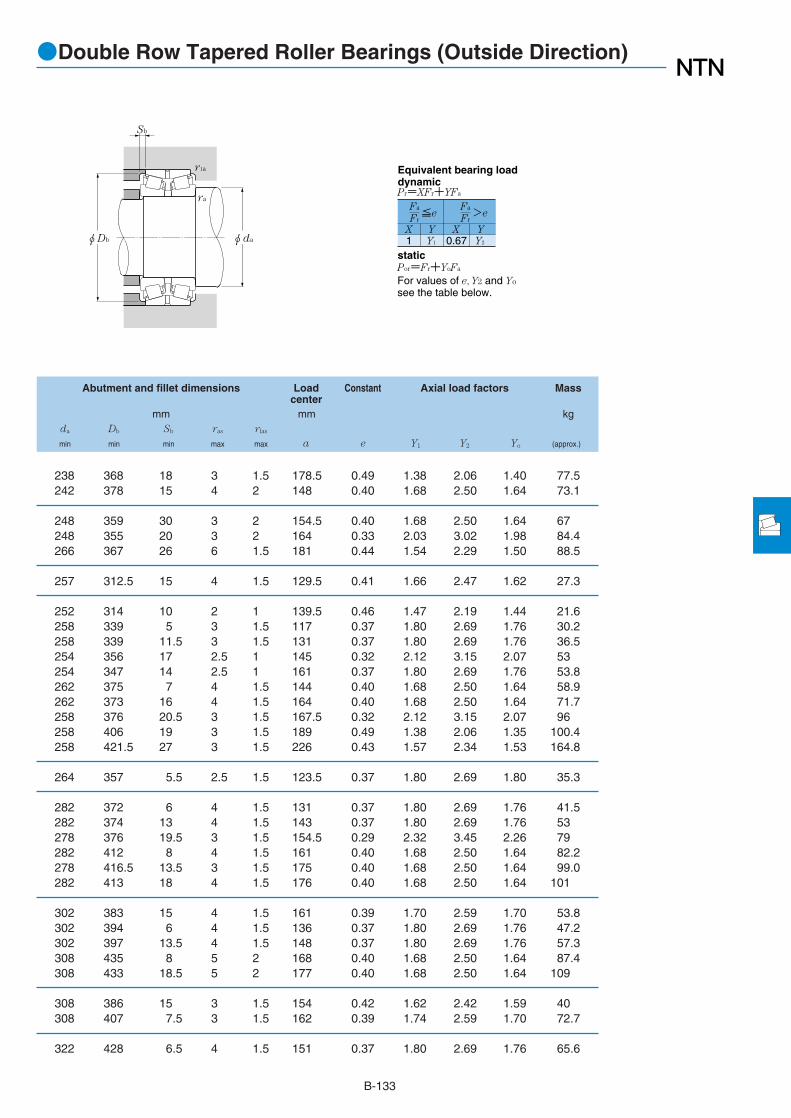
B-133
●Double Row Tapered Roller Bearings (Outside Direction)
φDb
Sb
φda
ra
r1a
1 Y1 0.67 Y2
Fa
Fr
X Y X Y
≦eFa
Fr>e
Pr=XFr+YFa
Por=Fr+YoFa
For values of e, Y2 and Yo
see the table below.
Equivalent bearing loaddynamic
static
Abutment and fillet dimensions Load Constant Axial load factors Masscenter
mm mm kgda Db Sb ras rlas
min min min max max a e Y1 Y2 Yo (approx.)
238 368 18 3 1.5 178.5 0.49 1.38 2.06 1.40 77.5242 378 15 4 2 148 0.40 1.68 2.50 1.64 73.1
248 359 30 3 2 154.5 0.40 1.68 2.50 1.64 67248 355 20 3 2 164 0.33 2.03 3.02 1.98 84.4266 367 26 6 1.5 181 0.44 1.54 2.29 1.50 88.5
257 312.5 15 4 1.5 129.5 0.41 1.66 2.47 1.62 27.3
252 314 10 2 1 139.5 0.46 1.47 2.19 1.44 21.6258 339 5 3 1.5 117 0.37 1.80 2.69 1.76 30.2258 339 11.5 3 1.5 131 0.37 1.80 2.69 1.76 36.5254 356 17 2.5 1 145 0.32 2.12 3.15 2.07 53254 347 14 2.5 1 161 0.37 1.80 2.69 1.76 53.8262 375 7 4 1.5 144 0.40 1.68 2.50 1.64 58.9262 373 16 4 1.5 164 0.40 1.68 2.50 1.64 71.7258 376 20.5 3 1.5 167.5 0.32 2.12 3.15 2.07 96258 406 19 3 1.5 189 0.49 1.38 2.06 1.35 100.4258 421.5 27 3 1.5 226 0.43 1.57 2.34 1.53 164.8
264 357 5.5 2.5 1.5 123.5 0.37 1.80 2.69 1.80 35.3
282 372 6 4 1.5 131 0.37 1.80 2.69 1.76 41.5282 374 13 4 1.5 143 0.37 1.80 2.69 1.76 53278 376 19.5 3 1.5 154.5 0.29 2.32 3.45 2.26 79282 412 8 4 1.5 161 0.40 1.68 2.50 1.64 82.2278 416.5 13.5 3 1.5 175 0.40 1.68 2.50 1.64 99.0282 413 18 4 1.5 176 0.40 1.68 2.50 1.64 101
302 383 15 4 1.5 161 0.39 1.70 2.59 1.70 53.8302 394 6 4 1.5 136 0.37 1.80 2.69 1.76 47.2302 397 13.5 4 1.5 148 0.37 1.80 2.69 1.76 57.3308 435 8 5 2 168 0.40 1.68 2.50 1.64 87.4308 433 18.5 5 2 177 0.40 1.68 2.50 1.64 109
308 386 15 3 1.5 154 0.42 1.62 2.42 1.59 40308 407 7.5 3 1.5 162 0.39 1.74 2.59 1.70 72.7
322 428 6.5 4 1.5 151 0.37 1.80 2.69 1.76 65.6

B-134
●Double Row Tapered Roller Bearings (Outside Direction)
Boundary dimensions Basic load ratings Bearingdynamic static dynamic static numbers
mm kN kgf
d D B1 C rs min1
rls min1
Cr Cor Cr Cor
1 Minimum allowable dimension for chamfer dimension r or r1.Remarks: 1. Bearing numbers marked "☆" designate bearing with hollow rollers and pin type cages.
d 300~400mm
φD
C
φd
a
B1
r
r1
Metric system sizes
460 148 118 5 1.5 1,610 3,150 165,000 320,000 423060500 160 142 6 2 2,010 3,600 205,000 370,000 413160500 200 160 6 2 2,100 4,050 214,000 415,000 423160540 208 158 5 2.5 2,440 4,450 249,000 450,000 CRI-6010
480 121 108 5 1.5 1,190 2,250 121,000 229,000 413064480 151 121 5 1.5 1,580 3,100 162,000 315,000 423064540 176 157 6 2 2,240 4,100 228,000 415,000 413164540 220 176 6 2 2,500 4,900 255,000 500,000 423164550 240 180 5 2.5 3,300 6,500 340,000 665,000 ☆CRI-6410
500 190 150 6 1.5 2,480 5,550 252,000 565,000 CRI-6603
460 160 128 3 1 1,630 4,250 167,000 430,000 CRI-6808500 249 203 5 1.5 2,690 6,200 274,000 630,000 CRI-6812520 133 118 6 2 1,480 2,870 150,000 293,000 413068520 165 133 6 2 1,890 3,750 193,000 380,000 423068580 190 169 6 2 2,690 4,900 274,000 500,000 413168580 238 190 6 2 3,350 6,500 345,000 660,000 423168
540 134 120 6 2 1,470 2,810 150,000 287,000 413072540 169 134 6 2 2,050 4,200 209,000 430,000 423072600 192 171 6 2 2,720 5,050 277,000 515,000 413172600 240 192 6 2 3,200 6,500 325,000 660,000 423172
508 139.7 88.9 6.4 1.5 920 2,270 94,000 232,000 CRI-7619560 135 122 6 2 1,690 3,350 172,000 340,000 413076560 171 135 6 2 2,080 4,350 213,000 445,000 423076620 194 173 6 2 2,840 5,250 289,000 535,000 413176620 241 170 5 2 3,700 7,400 380,000 755,000 CRI-7614620 243 194 6 2 3,350 6,700 340,000 685,000 423176
600 185 130 4 2 2,680 5,550 273,000 565,000 ☆CRI-7803
540 140 100 6.4 1.5 1,620 3,800 165,000 390,000 CRI-8005600 148 132 6 2 1,860 3,700 190,000 375,000 413080600 185 148 6 2 2,530 5,450 258,000 555,000 423080650 200 178 6 3 3,000 5,800 305,000 590,000 413180650 250 200 6 3 3,750 7,850 385,000 800,000 423180
300
320
330
340
360
380
390
400

B-135
●Double Row Tapered Roller Bearings (Outside Direction)
φDb
Sb
φda
ra
r1a
1 Y1 0.67 Y2
Fa
Fr
X Y X Y
≦eFa
Fr>e
Pr=XFr+YFa
Por=Fr+YoFa
For values of e, Y2 and Yo
see the table below.
Equivalent bearing loaddynamic
static
Abutment and fillet dimensions Load Constant Axial load factors Masscenter
mm mm kgda Db Sb ras rlas
min min min max max a e Y1 Y2 Yo (approx.)
322 434 15 4 1.5 163 0.37 1.80 2.69 1.76 80.2328 471 9 5 2 182 0.40 1.68 2.50 1.64 115328 467 20 5 2 202 0.40 1.68 2.50 1.64 144322 498 25 4 2 238 0.49 1.38 2.06 1.35 184
342 449 6.5 4 1.5 157 0.37 1.80 2.69 1.76 70.9342 455 15 4 1.5 170 0.37 1.80 2.69 1.76 85.4348 505 9.5 5 2 197 0.40 1.68 2.50 1.64 150348 504.5 22 5 2 217 0.40 1.68 2.50 1.64 186342 514 30 4 2 233 0.40 1.68 2.50 1.64 223
358 477 20 5 1.5 195 0.39 1.74 2.59 1.70 117
354 441 16 2.5 1 161.5 0.32 2.12 3.15 2.07 70362 481 23 4 1.5 218.5 0.33 2.03 3.02 1.98 154368 488 7.5 5 2 170 0.37 1.80 2.69 1.76 89.2368 489 16 5 2 184 0.37 1.80 2.69 1.76 113368 548 10.5 5 2 213 0.40 1.68 2.50 1.64 188368 542 24 5 2 237 0.40 1.68 2.50 1.64 235
388 507 7 5 2 176 0.37 1.80 2.69 1.76 98.2388 509 17.5 5 2 192 0.37 1.80 2.69 1.76 120388 561 10.5 5 2 219 0.40 1.68 2.50 1.64 199388 563 24 5 2 240 0.40 1.68 2.50 1.64 248
408 483 25.5 5 1.5 221 0.53 1.27 1.89 1.24 69.5408 528 6.5 5 2 183 0.37 1.80 2.69 1.76 95.9408 529 18 5 2 196 0.37 1.80 2.69 1.76 126408 583 10.5 5 2 225 0.40 1.68 2.50 1.64 210402 582 35.5 4 2 263 0.46 1.47 2.19 1.44 252408 578 24.5 5 2 249 0.40 1.68 2.50 1.64 262
408 564 27.5 3 2 216.5 0.40 1.70 2.50 1.66 175
428 519.5 20 5 1.5 216 0.48 1.41 2.09 1.37 80.6428 564 8 5 2 194 0.37 1.80 2.69 1.76 105428 564 18.5 5 2 210 0.37 1.80 2.69 1.76 163428 610 11 5 2.5 232 0.40 1.68 2.50 1.64 236428 610 25 5 2.5 256 0.40 1.68 2.50 1.64 294

B-136
●Double Row Tapered Roller Bearings (Outside Direction)
Boundary dimensions Basic load ratings Bearingdynamic static dynamic static numbers
mm kN kgf
d D B1 C rs min1
rls min1
Cr Cor Cr Cor
1 Minimum allowable dimension for chamfer dimension r or r1.Remarks: 1. Bearing numbers marked "☆" designate bearing with hollow rollers and pin type cages.
d 420~560mm
φD
C
φd
a
B1
r
r1
Metric system sizes
620 150 134 6 2 2,110 4,250 215,000 435,000 413084620 188 150 6 2 2,650 5,900 270,000 600,000 423084700 224 200 6 3 3,700 7,200 375,000 735,000 413184700 274 200 6 2.5 4,850 9,850 495,000 1,000,000 ☆CRI-8403700 280 224 6 3 4,800 9,700 490,000 990,000 423184
650 157 140 6 3 2,470 5,150 252,000 525,000 413088650 196 157 6 3 2,600 5,450 266,000 560,000 423088720 226 201 6 3 4,000 7,800 410,000 795,000 413188720 283 226 6 3 5,000 10,300 510,000 1,050,000 423188
680 163 145 6 3 2,600 5,350 265,000 550,000 413092680 204 163 6 3 3,100 6,750 315,000 685,000 423092760 240 214 7.5 4 4,550 9,150 465,000 930,000 413192760 300 240 7.5 4 4,900 10,300 500,000 1,050,000 423192
700 165 147 6 3 2,490 5,000 254,000 510,000 413096700 206 165 6 3 3,050 6,700 310,000 685,000 423096790 248 221 7.5 4 4,800 9,600 490,000 975,000 413196790 310 248 7.5 4 5,300 11,100 540,000 1,130,000 423196
670 180 130 5 2 2,400 6,100 245,000 625,000 CRI-10004720 167 149 6 3 2,610 5,400 266,000 550,000 4130/500720 209 167 6 3 3,050 6,900 315,000 700,000 4230/500830 264 235 7.5 4 5,200 10,500 530,000 1,070,000 4131/500830 330 264 7.5 4 6,400 14,000 650,000 1,420,000 ☆4231/500G2
780 185 163 6 3 2,910 5,900 297,000 600,000 4130/530780 231 185 6 3 4,050 9,050 415,000 920,000 4230/530870 272 239 7.5 4 6,000 12,200 615,000 1,240,000 ☆4131/530G2870 340 272 7.5 4 7,750 16,700 790,000 1,710,000 ☆4231/530AG2
735 225 180 6.4 1.5 3,150 8,800 325,000 895,000 CRI-11206740 190 140 6.4 1.5 2,360 6,250 241,000 640,000 CRI-11211820 195 173 6 3 3,600 7,850 370,000 800,000 ☆CRI-11214820 244 195 6 3 4,750 11,000 485,000 1,120,000 ☆CRI-11213920 280 246 7.5 4 5,900 12,100 600,000 1,230,000 4131/560920 350 280 7.5 4 7,600 17,400 775,000 1,780,000 ☆4231/560G2
420
440
460
480
500
530
560

B-137
●Double Row Tapered Roller Bearings (Outside Direction)
φDb
Sb
φda
ra
r1a
1 Y1 0.67 Y2
Fa
Fr
X Y X Y
≦eFa
Fr>e
Pr=XFr+YFa
Por=Fr+YoFa
For values of e, Y2 and Yo
see the table below.
Equivalent bearing loaddynamic
static
Abutment and fillet dimensions Load Constant Axial load factors Masscenter
mm mm kgda Db Sb ras rlas
min min min max max a e Y1 Y2 Yo (approx.)
448 586 8 5 2 200 0.37 1.80 2.69 1.76 135448 583 19 5 2 220 0.37 1.80 2.69 1.76 172448 655 12 5 2.5 258 0.40 1.68 2.50 1.64 317448 649 37 5 2 245 0.32 2.12 3.15 2.07 387448 659 28 5 2.5 287 0.40 1.68 2.50 1.64 394
468 618 8.5 5 2.5 208 0.37 1.80 2.69 1.76 160468 614 19.5 5 2.5 229 0.37 1.80 2.69 1.76 198468 675 12.5 5 2.5 263 0.40 1.68 2.50 1.64 330468 678 28.5 5 2.5 288 0.40 1.68 2.50 1.64 412
488 646 9 5 2.5 217 0.37 1.80 2.69 1.76 179488 644 20.5 5 2.5 239 0.37 1.80 2.69 1.76 225496 714 13 6 3 276 0.40 1.68 2.50 1.64 395496 712 30 6 3 305 0.40 1.68 2.50 1.64 493
508 665 9 5 2.5 223 0.37 1.80 2.69 1.76 189508 664 20.5 5 2.5 246 0.37 1.80 2.69 1.76 236516 743 13.5 6 3 281 0.40 1.68 2.50 1.64 442516 738 31 6 3 329 0.40 1.68 2.50 1.64 548
522 637 25 4 2 242 0.40 1.68 2.50 1.64 175528 686 9 5 2.5 230 0.37 1.80 2.69 1.76 202528 683 21 5 2.5 250 0.37 1.80 2.69 1.76 247536 780 14.5 6 3 296 0.40 1.68 2.50 1.64 528536 773 33 6 3 331 0.40 1.68 2.50 1.64 678
558 740 11 5 2.5 250 0.37 1.80 2.69 1.76 265558 738.5 23 5 2.5 276 0.37 1.80 2.69 1.76 331566 820 16.5 6 3 303 0.38 1.77 2.64 1.73 620566 822.5 34 6 3 340 0.39 1.74 2.59 1.70 774
588 709 22.5 5 1.5 257 0.35 1.95 2.90 1.91 232588 705.5 25 5 1.5 231 0.34 1.98 2.94 1.93 198588 777 11 5 2.5 277 0.39 1.74 2.59 1.70 340588 774 24.5 5 2.5 272 0.33 2.03 3.02 1.98 415596 865 17 6 3 326 0.40 1.68 2.50 1.64 1,310596 865 35 6 3 362 0.40 1.68 2.50 1.64 894

B-138
●Double Row Tapered Roller Bearings (Outside Direction)
Boundary dimensions Basic load ratings Bearingdynamic static dynamic static numbers
mm kN kgf
d D B1 C rs min1
rls min1
Cr Cor Cr Cor
1 Minimum allowable dimension for chamfer dimension r or r1.Remarks: 1. Bearing numbers marked "☆" designate bearing with hollow rollers and pin type cages.
d 570~1,115mm
φD
C
φd
a
B1
r
r1
Metric system sizes
815 345 265 6 3 6,300 16,600 640,000 1,690,000 CRI-11401
780 255 178 5 2.5 3,900 10,500 400,000 1,070,000 CRI-11801
870 200 176 6 3 3,900 8,550 400,000 870,000 4130/600980 300 264 7.5 4 7,400 15,400 755,000 1,570,000 ☆4131/600G2980 388 300 7.5 4 8,600 18,400 875,000 1,870,000 ☆4231/600G2
830 180 145 4 1.5 3,050 9,150 310,000 935,000 ☆CRI-13402880 185 130 4 2 3,500 9,100 360,000 930,000 ☆CRI-13401
1,090 336 295 7.5 4 9,250 19,700 945,000 2,010,000 ☆4131/670G21,090 392 336 7.5 4 10,500 24,800 1,070,000 2,530,000 ☆4231/670G2
1,030 236 208 7.5 4 5,900 13,900 600,000 1,420,000 ☆4130/710G21,030 236 208 7.5 4 5,750 14,000 590,000 1,430,000 ☆CRI-142071,030 295 236 7.5 4 6,900 16,100 700,000 1,640,000 ☆CRI-14209
1,150 350 256 7.5 4 9,350 24,200 955,000 2,470,000 ☆CRI-16001
1,290 350 270 6 2.5 8,850 30,000 900,000 3,050,000 ☆CRI-20802
1,460 300 220 5 2.5 8,200 24,000 835,000 2,450,000 ☆CRI-22303
570
590
600
670
710
800
1,115
1,040

B-139
●Double Row Tapered Roller Bearings (Outside Direction)
φDb
Sb
φda
ra
r1a
1 Y1 0.67 Y2
Fa
Fr
X Y X Y
≦eFa
Fr>e
Pr=XFr+YFa
Por=Fr+YoFa
For values of e, Y2 and Yo
see the table below.
Equivalent bearing loaddynamic
static
Abutment and fillet dimensions Load Constant Axial load factors Masscenter
mm mm kgda Db Sb ras rlas
min min min max max a e Y1 Y2 Yo (approx.)
598 781 40 5 2.5 318 0.35 1.95 2.90 1.91 512
612 754 38.5 4 2 288 0.39 1.74 2.59 1.70 291
628 828 12 5 2.5 277 0.37 1.80 2.69 1.76 348636 925 18 6 3 350 0.40 1.68 2.50 1.64 858636 923 44 6 3 380 0.38 1.77 2.64 1.73 1,050
688 809 17.5 3 1.5 283 0.40 1.68 2.50 1.64 201688 845.5 27.5 3 2 317 0.45 1.51 2.25 1.48 277706 1,033 20.5 6 3 397 0.40 1.68 2.50 1.64 1,180706 1,021 28 6 3 397 0.37 1.80 2.69 1.76 1,410
746 974 14 6 3 327 0.37 1.80 2.69 1.76 640746 974 14 6 3 324 0.36 1.87 2.79 1.83 654746 982 29.5 6 3 362 0.39 1.73 2.58 1.69 810
836 1,092.5 47 6 3 400 0.37 1.80 2.69 1.76 1,119
1,068 1,260 40 5 2 472.3 0.40 1.68 2.50 1.64 975
1,137 1,396.5 40 4 2 554 0.47 1.43 2.12 1.40 1,255
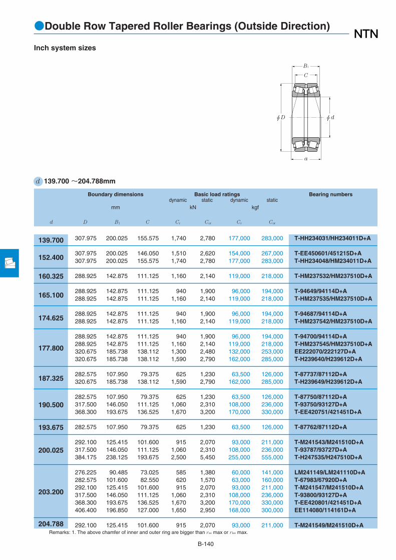
B-140
●Double Row Tapered Roller Bearings (Outside Direction)
Boundary dimensions Basic load ratings Bearing numbersdynamic static dynamic static
mm kN kgf
d D B1 C Cr Cor Cr Cor
Remarks: 1. The above chamfer of inner and outer ring are bigger than ras max or rlas max.
d 139.700 ~204.788mm
φD
C
φd
a
B1
Inch system sizes
307.975 200.025 155.575 1,740 2,780 177,000 283,000 T-HH234031/HH234011D+A
307.975 200.025 146.050 1,510 2,620 154,000 267,000 T-EE450601/451215D+A307.975 200.025 155.575 1,740 2,780 177,000 283,000 T-HH234048/HM234011D+A
288.925 142.875 111.125 1,160 2,140 119,000 218,000 T-HM237532/HM237510D+A
288.925 142.875 111.125 940 1,900 96,000 194,000 T-94649/94114D+A288.925 142.875 111.125 1,160 2,140 119,000 218,000 T-HM237535/HM237510D+A
288.925 142.875 111.125 940 1,900 96,000 194,000 T-94687/94114D+A288.925 142.875 111.125 1,160 2,140 119,000 218,000 T-HM237542/HM237510D+A
288.925 142.875 111.125 940 1,900 96,000 194,000 T-94700/94114D+A288.925 142.875 111.125 1,160 2,140 119,000 218,000 T-HM237545/HM237510D+A320.675 185.738 138.112 1,300 2,480 132,000 253,000 EE222070/222127D+A320.675 185.738 138.112 1,590 2,790 162,000 285,000 T-H239640/H239612D+A
282.575 107.950 79.375 625 1,230 63,500 126,000 T-87737/87112D+A320.675 185.738 138.112 1,590 2,790 162,000 285,000 T-H239649/H239612D+A
282.575 107.950 79.375 625 1,230 63,500 126,000 T-87750/87112D+A317.500 146.050 111.125 1,060 2,310 108,000 236,000 T-93750/93127D+A368.300 193.675 136.525 1,670 3,200 170,000 330,000 T-EE420751/421451D+A
282.575 107.950 79.375 625 1,230 63,500 126,000 T-87762/87112D+A
292.100 125.415 101.600 915 2,070 93,000 211,000 T-M241543/M241510D+A317.500 146.050 111.125 1,060 2,310 108,000 236,000 T-93787/93727D+A384.175 238.125 193.675 2,500 5,450 255,000 555,000 T-H247535/H247510D+A
276.225 90.485 73.025 585 1,380 60,000 141,000 LM241149/LM241110D+A282.575 101.600 82.550 620 1,570 63,000 160,000 T-67983/67920D+A292.100 125.415 101.600 915 2,070 93,000 211,000 T-M241547/M241510D+A317.500 146.050 111.125 1,060 2,310 108,000 236,000 T-93800/93127D+A368.300 193.675 136.525 1,670 3,200 170,000 330,000 T-EE420801/421451D+A406.400 196.850 127.000 1,650 2,950 168,000 300,000 EE114080/114161D+A
292.100 125.415 101.600 915 2,070 93,000 211,000 T-M241549/M241510D+A
139.700
152.400
160.325
165.100
174.625
177.800
187.325
190.500
193.675
200.025
203.200
204.788

B-141
●Double Row Tapered Roller Bearings (Outside Direction)
φDb φda
ra
r1a
1 Y1 0.67 Y2
Fa
Fr
X Y X Y
≦eFa
Fr>e
Pr=XFr+YFa
Equivalent bearing loaddynamic
Por=Fr+YoFa
For values of e, Y2 and Yo
see the table below.
static
Abutment and fillet dimensions Load Constant Axial load factors Masscenter
mm mm kgda Db ras rlas
min max max max a e Y1 Y2 Yo (approx.)
180 285 9.7 2.3 149.5 0.33 2.07 3.08 2.02 65.9
189 275 9.7 2.3 143.5 0.33 2.07 3.08 2.02 62.6191 285 9.7 2.3 149.5 0.33 2.07 3.08 2.02 62.6
192 271 7 1.5 119.5 0.32 2.12 3.15 2.07 36.1
197 272 7 1.5 141 0.47 1.44 2.15 1.41 35.1195 271 7 1.5 119.5 0.32 2.12 3.15 2.07 35.1
204 272 7 1.5 141 0.47 1.44 2.15 1.41 33.1202 271 7 1.5 119.5 0.32 2.12 3.15 2.07 33.1
207 272 7 1.5 141 0.47 1.44 2.15 1.41 32.4205 271 7 1.5 119.5 0.32 2.12 3.15 2.07 32.4204 298 3.5 1.5 152.5 0.40 1.68 2.50 1.64 57.8202 301 3.5 1.5 141 0.32 2.12 3.15 2.07 57.8
207 267 3.5 1.5 115.5 0.42 1.62 2.42 1.59 21.1214 301 5.5 1.5 141 0.32 2.12 3.15 2.07 55
209 267 3.5 1.5 115.5 0.42 1.62 2.42 1.59 20.6218 300 4.3 1.5 162 0.52 1.29 1.92 1.26 41.2227 334.4 6.4 1.5 163 0.40 1.68 2.50 1.64 84.1
211 267 3.5 1.5 115.5 0.42 1.62 2.42 1.59 20
219 279 3.5 1.5 116 0.33 2.03 3.02 1.98 24.8225 300 4.3 1.5 162 0.52 1.29 1.92 1.26 38.8241 362 6.4 1.5 182 0.33 2.03 3.02 1.98 112
220 267 3.5 0.8 95 0.32 2.12 3.15 2.07 13.8222 275 3.5 0.8 133.5 0.51 1.33 1.97 1.30 17.1221 279 3.5 1.5 116 0.33 2.03 3.02 1.98 24.1227 300 4.3 1.5 162 0.52 1.29 1.92 1.26 37.1230 334.4 3.3 1.5 163 0.40 1.68 2.50 1.64 79.9246 374 6.4 3.3 252.5 0.80 0.85 1.26 0.83 107
223 279 3.5 1.5 116 0.33 2.03 3.02 1.98 23.8

B-142
●Double Row Tapered Roller Bearings (Outside Direction)
Boundary dimensions Basic load ratings Bearing numbersdynamic static dynamic static
mm kN kgf
d D B1 C Cr Cor Cr Cor
Remarks: 1. The above chamfer of inner and outer ring are bigger than ras max or rlas max.2. Bearing numbers marked "☆" designate bearing with hollow rollers and pin type cages.
d 206.375~241.300mm
φD
C
φd
a
B1
Inch system sizes
282.575 101.600 82.550 620 1,570 63,000 160,000 T-67985/67920D+A336.550 211.138 169.862 1,900 4,050 194,000 415,000 T-H242649/H242610D+A
282.575 101.600 82.550 620 1,570 63,000 160,000 T-67989/67920D+A317.500 146.050 111.125 1,060 2,310 108,000 236,000 T-93825/93127D+A
285.750 98.425 76.200 650 1,640 66,500 167,000 T-LM742745/LM742710D+A
285.750 98.425 76.200 650 1,640 66,500 167,000 T-LM742749/LM742710D+A287.338 69.850 50.800 355 810 36,000 82,500 543085/543115D+A
314.325 131.762 106.362 1,070 2,450 109,000 250,000 T-M244249/M244210D+A
431.800 196.850 111.125 1,470 2,480 150,000 253,000 EE113091/113171D+A
327.025 114.300 82.550 815 1,900 83,000 194,000 T-8573/8520D+A355.600 152.400 111.125 1,100 2,540 112,000 259,000 T-96900/96140D+A355.600 152.400 111.125 1,230 2,510 125,000 256,000 T-EE130902/131401D+A355.600 152.400 114.300 1,230 2,490 126,000 254,000 HM746646/HM746610D+A358.775 152.400 117.475 1,390 3,300 142,000 335,000 T-M249732/M249710D+A400.050 187.325 136.525 1,620 3,250 165,000 330,000 EE430900/431576D+A488.950 254.000 152.400 2,700 4,550 275,000 460,000 ☆T-HH949549/HH949510DG2+A
358.775 152.400 117.475 1,390 3,300 142,000 335,000 T-M249734/M249710D+A
311.150 98.425 73.025 695 1,640 71,000 167,000 LM446349/LM446310D+A327.025 114.300 82.550 815 1,900 83,000 194,000 T-8575/8520D+A355.600 152.400 111.125 1,100 2,540 112,000 259,000 T-96925/96140D+A384.175 238.125 193.675 2,500 5,450 255,000 555,000 T-H247549/H247510D+A
358.775 152.400 117.475 1,390 3,300 142,000 335,000 T-M249736/M249710D+A
327.025 114.300 82.550 815 1,900 83,000 194,000 T-8578/8520D+A349.148 127.000 101.600 940 2,010 96,000 205,000 EE127095/127136D+A368.300 120.650 85.725 790 1,630 80,500 166,000 EE170950/171450D+A393.700 157.162 109.538 1,340 2,800 137,000 286,000 T-EE275095/275156D+A406.400 215.900 184.150 2,460 4,750 251,000 485,000 T-H249148/H249111D+A444.500 209.550 158.750 2,380 4,250 243,000 430,000 ☆T-EE923095/923176DG2+A
206.375
209.550
212.725
215.900
220.662
228.460
228.600
231.775
234.950
237.330
241.300

B-143
●Double Row Tapered Roller Bearings (Outside Direction)
φDb φda
ra
r1a
1 Y1 0.67 Y2
Fa
Fr
X Y X Y
≦eFa
Fr>e
Pr=XFr+YFa
Equivalent bearing loaddynamic
Por=Fr+YoFa
For values of e, Y2 and Yo
see the table below.
static
Abutment and fillet dimensions Load Constant Axial load factors Masscenter
mm mm kgda Db ras rlas
min max max max a e Y1 Y2 Yo (approx.)
224 275 3.5 0.8 133.5 0.51 1.33 1.97 1.30 16.5231 318 3.3 1.5 160 0.33 2.03 3.02 1.98 65.2
227 275 3.5 0.8 133.5 0.51 1.33 1.97 1.30 16233 300 4.3 1.5 161 0.52 1.29 1.92 1.26 36.3
230 279 3.5 0.8 126.5 0.48 1.40 2.09 1.37 15.7
233 279 3.5 0.8 126.5 0.48 1.40 2.09 1.37 15.1232 276 3.5 0.8 94.5 0.38 1.77 2.64 1.73 11
245 300 6.4 1.5 122.5 0.33 2.03 3.02 1.98 28.9
274 397 6.4 3.3 276 0.88 0.77 1.14 0.75 116
255 313 6.4 1.5 129.5 0.41 1.66 2.47 1.62 27.3260 334 7 1.5 185 0.59 1.14 1.70 1.12 49.4257 330 6.8 1.5 132.5 0.33 2.04 3.04 2.00 49.4258 339 6.4 1.5 164 0.47 1.43 2.12 1.40 49.4256 343 3.5 1.5 138.5 0.33 2.03 3.02 1.98 50.9271 367 10.5 1.5 181.5 0.44 1.54 2.29 1.50 88.3297 456 6.4 1.5 333.5 0.94 0.72 1.07 0.70 207
263 343 6.4 1.5 138.5 0.33 2.03 3.02 1.98 50
252 301 3.5 0.8 111.5 0.36 1.86 2.77 1.82 17.9259 313 6.4 1.5 129.5 0.41 1.66 2.47 1.62 25.9265 334 7 1.5 185 0.59 1.14 1.70 1.12 47.5269 362 6.4 1.5 181.5 0.33 2.03 3.02 1.98 96.2
267 343 6.4 1.5 138.5 0.33 2.03 3.02 1.98 48.2
264 313 6.4 1.5 129.5 0.41 1.66 2.47 1.62 24.3267 329 6.4 1.5 133 0.35 1.91 2.85 1.87 35.4269 337 6.4 1.5 132.5 0.36 1.85 2.76 1.81 40.8278 378.1 6.4 1.5 162 0.40 1.68 2.50 1.64 66.5273 385 6.4 1.5 177.5 0.33 2.03 3.02 1.98 101277 407 6.4 1.5 170.5 0.34 2.00 2.98 1.96 128

B-144
●Double Row Tapered Roller Bearings (Outside Direction)
Boundary dimensions Basic load ratings Bearing numbersdynamic static dynamic static
mm kN kgf
d D B1 C Cr Cor Cr Cor
Remarks: 1. The above chamfer of inner and outer ring are bigger than ras max or rlas max.
d 244.475~280.192mm
φD
C
φd
a
B1
Inch system sizes
381.000 171.450 127.000 1,300 2,880 132,000 294,000 EE126097/126151D+A
368.300 120.650 85.725 790 1,630 80,500 166,000 EE170975/171451D+A406.400 247.650 203.200 2,830 6,000 289,000 615,000 HH249949/HH249910D+A
381.000 171.450 127.000 1,300 2,880 132,000 294,000 EE126098/126151D+A
323.850 63.500 50.800 216 635 22,000 64,500 29875/29820D+A358.775 152.400 117.475 1,390 3,300 142,000 335,000 T-M249749/M249710D+A365.125 130.175 98.425 1,050 2,380 107,000 243,000 T-EE134100/134144D+A393.700 157.162 109.538 1,340 2,800 137,000 286,000 T-EE275100/275156D+A422.275 178.592 139.700 2,000 3,600 204,000 365,000 T-HM252343/HM252310D+A533.400 276.225 165.100 2,880 5,200 293,000 530,000 HH953749/HH953710D+A
365.125 130.175 98.425 1,050 2,380 107,000 243,000 T-EE134102/134144D+A400.050 155.575 107.950 1,220 2,460 124,000 251,000 EE221026/221576D+A419.100 184.150 136.525 1,580 3,250 161,000 330,000 EE435102/435165D+A422.275 178.592 139.700 2,000 3,600 204,000 365,000 T-HM252348/HM252310D+A488.950 254.000 196.850 3,000 5,950 310,000 605,000 EE295102/295192D+A
355.600 127.000 101.600 1,070 2,670 110,000 272,000 T-LM451345/LM451310D+A
323.850 63.500 50.800 216 635 22,000 64,500 29880/29820D+A355.600 127.000 101.600 1,070 2,670 110,000 272,000 T-LM451349/LM451310D+A393.700 157.162 109.538 1,340 2,800 137,000 286,000 T-EE275105/275156D+A
381.000 158.750 123.825 1,520 3,600 155,000 365,000 T-M252349/M252310D+A
393.700 157.162 109.538 1,340 2,800 137,000 286,000 T-EE275108/275156D+A
374.650 104.775 79.375 810 2,020 82,500 206,000 L555233/L555210D+A469.900 200.025 149.225 2,030 4,350 207,000 445,000 EE722110/722186D+A488.950 254.000 196.850 3,000 5,950 310,000 605,000 EE295110/295192D+A
380.898 139.700 107.950 1,140 3,100 116,000 315,000 T-LM654642/LM654610D+A
406.400 149.225 117.475 1,310 3,100 133,000 315,000 EE128111/128160D+A
244.475
247.650
249.250
254.000
260.350
263.525
266.700
269.875
273.050
279.400
279.982
280.192

B-145
●Double Row Tapered Roller Bearings (Outside Direction)
φDb φda
ra
r1a
1 Y1 0.67 Y2
Fa
Fr
X Y X Y
≦eFa
Fr>e
Pr=XFr+YFa
Equivalent bearing loaddynamic
Por=Fr+YoFa
For values of e, Y2 and Yo
see the table below.
static
Abutment and fillet dimensions Load Constant Axial load factors Masscenter
mm mm kgda Db ras rlas
min max max max a e Y1 Y2 Yo (approx.)
275 358 6.4 1.5 186.5 0.52 1.31 1.95 1.28 64
274 337 6.4 1.5 132.5 0.36 1.85 2.76 1.81 39.2284 383 6.4 1.5 189.5 0.33 2.03 3.02 1.98 112
279 358 6.4 1.5 186.5 0.52 1.31 1.95 1.28 62.2
267 312 1.5 0.8 105 0.35 1.95 2.90 1.91 11.2274 343 3.5 1.5 138.5 0.33 2.03 3.02 1.98 42.8281 347 6.4 1.5 140 0.37 1.80 2.69 1.76 39.2287 378 6.4 1.5 162.5 0.40 1.68 2.50 1.64 62.2287 400 6.8 1.5 160 0.33 2.03 3.02 1.98 88.9328 496 6.4 1.5 365.5 0.94 0.71 1.06 0.70 266
286 347 6.4 1.5 140 0.37 1.80 2.69 1.76 37.3296 372 9.7 1.5 159 0.39 1.71 2.54 1.67 62.7295 395 6.4 1.5 225.5 0.61 1.11 1.66 1.09 86.8292 400 6.8 1.5 160 0.33 2.03 3.02 1.98 86.3299 451 6.4 1.5 196.5 0.31 2.16 3.22 2.12 190
283 343 3.5 1.5 136.5 0.36 1.87 2.79 1.83 31.7
277 312 1.5 0.8 105 0.35 1.95 2.90 1.91 9.37285 343 3.5 1.5 136.5 0.36 1.87 2.79 1.83 30.7296 378 6.4 1.5 162.5 0.40 1.68 2.50 1.64 57.6
296 364 6.4 1.5 146.5 0.33 2.03 3.02 1.98 52.3
301 378 6.4 1.5 162.5 0.40 1.68 2.50 1.64 55.3
300 362 3.5 1.5 138.5 0.40 1.68 2.50 1.64 28.5321 433 9.7 1.5 187.5 0.38 1.78 2.65 1.74 125303 451 1.3 1.5 196.5 0.31 2.16 3.22 2.12 179
302 368 3.5 1.5 163 0.43 1.56 2.33 1.53 40.7
309 384 6.8 1.5 158 0.39 1.75 2.61 1.71 56.5

B-146
●Double Row Tapered Roller Bearings (Outside Direction)
Boundary dimensions Basic load ratings Bearing numbersdynamic static dynamic static
mm kN kgf
d D B1 C Cr Cor Cr Cor
Remarks: 1. The above chamfer of inner and outer ring are bigger than ras max or rlas max.2. Bearing numbers marked "☆" designate bearing with hollow rollers and pin type cages.
d 285.750~355.600mm
φD
C
φd
a
B1
Inch system sizes
358.775 76.200 53.975 450 1,080 46,000 110,000 545112/545142DA+A380.898 139.700 107.950 1,140 3,100 116,000 315,000 T-LM654649/LM654610D+A501.650 203.200 120.650 1,960 3,700 200,000 375,000 EE147112/147198D+A
406.400 165.100 130.175 1,740 4,150 177,000 425,000 M255449/M255410DA+A
374.650 104.775 79.375 810 2,020 82,500 206,000 L555249/L555210D+A469.900 200.025 149.225 2,030 4,350 207,000 445,000 EE722115/722186D+A
444.500 146.050 98.425 1,080 2,300 110,000 234,000 EE291175/291751D+A
495.300 301.625 247.650 4,200 9,800 425,000 1,000,000 ☆HH258248/HH258210DG2+A
422.275 174.625 136.525 1,950 4,800 198,000 490,000 ☆T-HM256849/HM256810DG2+A
393.700 107.950 82.550 835 2,070 85,500 211,000 L357049/L357010D+A438.048 165.100 120.650 1,380 3,200 141,000 325,000 T-EE129120X/129120D+A444.500 146.050 98.425 1,080 2,300 110,000 234,000 EE291201/291751D+A495.300 196.850 146.050 2,120 4,700 216,000 480,000 EE724120/724196D+A
444.500 146.050 98.425 1,080 2,300 110,000 234,000 EE291250/291751D+A447.675 180.975 146.050 1,990 4,800 203,000 485,000 T-HM259049/HM259010D+A622.300 304.800 174.625 3,250 6,250 330,000 640,000 ☆H961649/H961610DG2+A
482.600 133.350 88.900 1,200 2,870 122,000 293,000 T-EE161300/161901D+A482.600 177.800 127.000 1,640 3,950 167,000 400,000 EE526130/526191D+A
469.900 190.500 152.400 2,320 5,500 237,000 565,000 HM261049/HM261010DA+A
457.098 142.875 104.775 1,210 3,300 124,000 335,000 LM961548/LM961511D+A533.400 165.100 114.300 1,830 3,450 187,000 355,000 EE971354/972102D+A
482.600 133.350 88.900 1,200 2,870 122,000 293,000 T-EE161363/161901D+A488.950 200.025 158.750 2,540 6,400 259,000 650,000 ☆T-HM262749/HM262710DG2+A
514.350 193.675 152.400 2,040 4,550 209,000 465,000 EE333137/333203D+A
444.500 136.525 111.125 1,120 3,500 114,000 355,000 T-L163149/L163110D+A482.600 133.350 88.900 1,200 2,870 122,000 293,000 T-EE161400/161901D+A
285.750
288.925
292.100
298.450
299.974
300.038
304.800
317.500
330.200
333.375
342.900
346.075
349.250
355.600

B-147
●Double Row Tapered Roller Bearings (Outside Direction)
φDb φda
ra
r1a
1 Y1 0.67 Y2
Fa
Fr
X Y X Y
≦eFa
Fr>e
Pr=XFr+YFa
Equivalent bearing loaddynamic
Por=Fr+YoFa
For values of e, Y2 and Yo
see the table below.
static
Abutment and fillet dimensions Load Constant Axial load factors Masscenter
mm mm kgda Db ras rlas
min max max max a e Y1 Y2 Yo (approx.)
302 345 3.5 1.5 144 0.49 1.38 2.05 1.34 15.7306 368 3.5 1.5 163 0.43 1.56 2.33 1.53 38.7329 468 6.4 3.3 307 0.84 0.81 1.20 0.79 151
316 388 6.4 1.5 157 0.34 2.00 2.98 1.96 59
309 362 3.5 1.5 138.5 0.40 1.68 2.50 1.64 25.2330 433 9.7 1.5 187.5 0.38 1.78 2.65 1.74 118
332 414 8 1.5 164 0.38 1.78 2.65 1.74 69.3
342 467 6.4 1.5 231 0.33 2.03 3.02 1.98 205
328 403 6.4 1.5 163.5 0.34 2.00 2.99 1.96 67.4
329 380 6.4 1.5 133 0.36 1.87 2.79 1.83 29.3334 411 6.4 1.5 179.5 0.42 1.62 2.42 1.59 71.4337 414 8 1.5 164 0.38 1.78 2.65 1.74 66.8359 459 16 1.5 195 0.40 1.68 2.50 1.64 131
346 414 8 1.5 164 0.38 1.78 2.65 1.74 61.8341 428 3.5 1.5 162 0.33 2.02 3.00 1.97 78.8410 582 14.3 3.3 430 0.95 0.71 1.06 0.70 382
367 455 7 1.5 200.5 0.50 1.35 2.01 1.32 72.2360 454 6.4 1.5 183.5 0.39 1.72 2.56 1.68 96.3
363 449 6.4 1.5 179.5 0.33 2.02 3.00 1.97 91.3
367 443.1 3.3 1.5 253.5 0.71 0.95 1.41 0.93 57.1373 496 4.8 1.5 170 0.33 2.03 3.02 1.98 120
379 455 7 1.5 200.5 0.50 1.35 2.01 1.32 66377 467 6.4 1.5 187.5 0.33 2.02 3.00 1.97 104
382 478 6.4 1.5 197.5 0.36 1.85 2.76 1.81 121
374 430 3.5 1.5 151 0.31 2.20 3.27 2.15 42.5386 455 7 1.5 200.5 0.50 1.35 2.01 1.32 62.1

B-148
●Double Row Tapered Roller Bearings (Outside Direction)
Boundary dimensions Basic load ratings Bearing numbersdynamic static dynamic static
mm kN kgf
d D B1 C Cr Cor Cr Cor
Remarks: 1. The above chamfer of inner and outer ring are bigger than ras max or rlas max.2. Bearing numbers marked "☆" designate bearing with hollow rollers and pin type cages.
d 355.600~482.600mm
φD
C
φd
a
B1
Inch system sizes
501.650 155.575 107.950 1,550 3,650 158,000 375,000 T-EE231400/231976D+A514.350 193.675 152.400 2,040 4,550 209,000 465,000 EE333140/333203D+A
523.875 214.312 169.862 2,610 6,550 266,000 665,000 ☆HM265049/HM265010DG2+A
501.650 155.575 107.950 1,550 3,650 158,000 375,000 T-EE231462/231976D+A
508.000 139.700 88.900 920 2,270 94,000 232,000 EE192150/192201D+A546.100 222.250 177.800 2,950 7,350 300,000 750,000 T-HM266446/HM266410D+A590.550 244.475 193.675 3,650 9,450 375,000 965,000 ☆T-M268730/M268710DG2+A
441.325 68.262 52.388 360 1,060 36,500 108,000 LL365340/LL365310D+A546.100 222.250 177.800 2,950 7,350 300,000 750,000 T-HM266448/HM266410D+A546.100 222.250 177.800 3,150 8,050 320,000 820,000 ☆T-HM266449/HM266410DG2+A
514.350 177.800 139.700 2,120 5,550 216,000 565,000 LM665949/LM665910D+A
539.750 142.875 101.600 1,330 3,300 136,000 335,000 EE234156/234213D+A546.100 158.750 117.475 1,330 3,300 136,000 335,000 EE234156/234216D+A
539.750 142.875 101.600 1,330 3,300 136,000 335,000 EE234160/234213D+A609.600 187.325 123.825 2,110 4,650 215,000 475,000 EE911600/912401D+A
590.550 244.475 193.675 3,650 9,450 375,000 965,000 ☆T-M268749/M268710DG2+A
571.500 155.575 111.125 1,880 4,950 191,000 505,000 T-LM869448/LM869410D+A603.250 159.639 104.775 1,670 4,100 171,000 420,000 EE241701/242377D+A673.100 192.639 127.000 2,560 5,350 261,000 545,000 EE571703/572651D+A
635.000 257.175 206.375 4,150 11,100 425,000 1,130,000 ☆M270749/M270710DAG2+A
596.900 165.100 120.650 1,670 4,700 170,000 480,000 EE244180/244236D+A730.148 254.000 177.800 4,350 8,750 445,000 895,000 EE671801/672875D+A
679.450 276.225 222.250 4,900 13,000 500,000 1,320,000 ☆T-M272749/M272710DG2+A
615.950 184.150 146.050 2,320 6,700 237,000 685,000 ☆LM272249/LM272210DG2+A634.873 177.800 142.875 2,000 6,150 204,000 630,000 EE243190/243251D+A
355.600
368.249
371.475
381.000
384.175
385.762
396.875
406.400
415.925
431.800
447.675
457.200
479.425
482.600

B-149
●Double Row Tapered Roller Bearings (Outside Direction)
φDb φda
ra
r1a
1 Y1 0.67 Y2
Fa
Fr
X Y X Y
≦eFa
Fr>e
Pr=XFr+YFa
Equivalent bearing loaddynamic
Por=Fr+YoFa
For values of e, Y2 and Yo
see the table below.
static
Abutment and fillet dimensions Load Constant Axial load factors Masscenter
mm mm kgda Db ras rlas
min max max max a e Y1 Y2 Yo (approx.)
388 481 6.4 1.5 195 0.44 1.53 2.28 1.50 85.2387 478 6.4 1.5 197.5 0.36 1.85 2.76 1.81 117
400 499 6.4 1.5 198.5 0.33 2.03 3.02 1.98 142
400 481 6.4 1.5 195 0.44 1.53 2.28 1.50 77.3
410 482 6.4 1.5 221 0.53 1.27 1.89 1.24 69415 519 6.4 1.5 208 0.33 2.03 3.02 1.98 149425 561 6.4 1.5 226 0.33 2.03 3.02 1.98 247
399 433 3.5 0.8 128.5 0.34 1.99 2.96 1.94 14.1417 519 6.4 1.5 208 0.33 2.03 3.02 1.98 146417 520 6.4 1.5 208 0.33 2.03 3.02 1.98 146
415 495 6.4 1.5 210.5 0.42 1.61 2.40 1.58 90
428 516 6.4 1.5 214.5 0.47 1.43 2.12 1.40 83.6428 516 6.4 1.5 230.5 0.47 1.43 2.12 1.40 97.7
435 518 6.4 1.5 214.5 0.47 1.43 2.12 1.40 78.8443 570 6.8 1.5 209 0.38 1.76 2.62 1.72 169
451 561 6.4 1.5 226 0.33 2.03 3.02 1.98 188
457 549 3.3 1.5 255.5 0.55 1.24 1.84 1.21 95.3446 561 6.4 1.5 252.5 0.53 1.28 1.91 1.25 124472 630 6.4 1.5 235.5 0.40 1.68 2.50 1.64 225
484 606 6.4 1.5 240 0.33 2.03 3.02 1.98 228
494 570 9.7 1.5 219 0.40 1.67 2.49 1.63 106507 681 9.7 1.5 266 0.39 1.72 2.56 1.68 360
516 648 6.4 1.5 258.5 0.33 2.03 3.02 1.98 310
513 597 6.4 1.5 206.5 0.33 2.03 3.02 1.98 118516 609 6.4 1.5 215 0.34 1.98 2.94 1.93 148

B-150
●Double Row Tapered Roller Bearings (Outside Direction)
Boundary dimensions Basic load ratings Bearing numbersdynamic static dynamic static
mm kN kgf
d D B1 C Cr Cor Cr Cor
Remarks: 1. The above chamfer of inner and outer ring are bigger than ras max or rlas max.2. Bearing numbers marked "☆" designate bearing with hollow rollers and pin type cages.
d 488.950~1,270.000mm
φD
C
φd
a
B1
Inch system sizes
634.873 180.975 136.525 2,500 6,950 255,000 710,000 LM772748/LM772710DA+A660.400 206.375 158.750 3,150 8,050 320,000 820,000 ☆T-EE640192/640261DG2+A
634.873 177.800 142.875 2,000 6,150 204,000 630,000 EE243192/243251D+A
634.873 177.800 142.875 2,000 6,150 204,000 630,000 EE243196/243251D+A
838.200 304.800 222.250 5,450 12,800 555,000 1,310,000 EE426200/426331D+A
812.800 269.875 187.325 4,450 10,400 455,000 1,060,000 EE626210/626321D+A
761.873 311.150 247.650 5,900 15,200 600,000 1,550,000 ☆M276449/M276410DG2+A
692.150 174.625 136.525 2,320 6,950 236,000 710,000 L476549/L476510D+A
736.600 165.100 114.300 2,050 5,400 209,000 550,000 EE542220/542291D+A736.600 187.328 138.112 2,500 6,750 255,000 690,000 EE843220/843291D+A736.600 225.425 177.800 3,150 8,800 325,000 895,000 LM377449/LM377410D+A
812.800 333.375 263.525 6,950 18,300 710,000 1,870,000 ☆M278749/M278710DAG2+A
787.400 206.375 158.750 3,750 10,100 380,000 1,030,000 ☆EE649240/649311DG2+A812.800 190.500 146.050 2,860 7,850 292,000 800,000 EE743240/743321D+A
812.800 203.200 158.750 3,250 10,300 330,000 1,060,000 L281148/L281110DA+A
914.400 190.500 139.700 3,100 8,950 315,000 910,000 ☆EE755280/755361DG2+A
914.400 187.325 139.700 3,100 8,950 315,000 910,000 ☆EE755285/755361DG2+A
1,130.300 139.700 101.600 2,050 7,200 209,000 735,000 LL687949/LL687910D+A
1,435.100 146.050 101.600 2,730 10,100 278,000 1,030,000 LL889049/LL889010D+A
488.950
489.026
498.475
508.000
533.400
536.575
549.275
558.800
571.500
609.600
660.400
711.200
723.900
977.900
1,270.000

B-151
●Double Row Tapered Roller Bearings (Outside Direction)
φDb φda
ra
r1a
1 Y1 0.67 Y2
Fa
Fr
X Y X Y
≦eFa
Fr>e
Pr=XFr+YFa
Equivalent bearing loaddynamic
Por=Fr+YoFa
For values of e, Y2 and Yo
see the table below.
static
Abutment and fillet dimensions Load Constant Axial load factors Masscenter
mm mm kgda Db ras rlas
min max max max a e Y1 Y2 Yo (approx.)
522 613 6.4 1.5 262 0.47 1.43 2.12 1.40 130522 627 6.4 1.5 216 0.31 2.20 3.27 2.15 178
522 609 6.4 1.5 215 0.34 1.98 2.94 1.93 140
528 609 6.4 1.5 215 0.34 1.98 2.94 1.93 129
564 768 9.7 3.3 357 0.48 1.41 2.09 1.37 592
585 762 9.7 3.3 322.5 0.44 1.52 2.26 1.49 444
576 726 6.4 1.5 290 0.33 2.03 3.02 1.98 398
579 666 6.4 1.5 239 0.38 1.79 2.67 1.75 135
594 705 6.4 3.3 298 0.51 1.32 1.96 1.29 166591 708 6.4 1.5 231 0.34 1.98 2.94 1.93 189594 708 6.4 1.5 256.5 0.35 1.95 2.90 1.91 227
615 774 6.4 1.5 308 0.33 2.03 3.02 1.98 487
642 764 6.4 1.5 254 0.33 2.03 3.02 1.98 235645 765 6.4 3.3 254 0.33 2.06 3.06 2.01 241
693 789 6.4 1.5 667.5 0.37 1.80 2.69 1.76 199
750 876 6.4 3.3 295.5 0.38 1.77 2.64 1.73 275
756 876 5.5 3.3 295.5 0.38 1.77 2.64 1.73 256
1,010 1,100 6.4 3.3 376 0.44 1.54 2.30 1.51 196
1,305 1,400 6.4 3.3 586.5 0.58 1.17 1.75 1.15 285

Metric system sizes
B-152
●Double Row Tapered Roller Bearings (Inside Direction)
Boundary dimensions Basic load ratings Bearing numbersdynamic static dynamic static
mm kN kgf
d D B C1 rs min1
rls min1
Cr Cor Cr Cor
1 Minimum allowable dimension for chamfer dimension r or r1. 2 "-" means the load center is out side the inner ring.Remarks: 1. The marked "*" bearings are inch system sizes.
d 100~180mm
φd
r
φD
C1
a
r1
B
250 116 116 4 4 790 1,050 80,500 107,000 CRD-2051
170 90 90 2.5 2.5 420 860 42,500 87,500 CRD-2151
180 56 56 2 2.5 298 485 30,500 49,500 323122190 102 98 3 1.5 515 950 52,500 96,500 CRD-2252200 82 82 2.5 1 555 865 56,500 88,500 CRD-2254
170 120 120 2 2 415 890 42,500 91,000 CRD-2421180 46 46 2 2.5 230 375 23,500 38,000 323024200 62 62 2 2.5 370 610 38,000 62,500 323124215 113 113 2.5 2.5 735 1,300 75,000 133,000 CRD-2420280 150 140 3 3 1,130 1,840 115,000 187,000 CRD-2422
190 120 120 1.5 1.5 415 840 42,000 85,500 CRD-2652195 120 120 2.5 1.5 475 1,040 48,500 106,000 CRD-2654200 52 52 2 2.5 294 490 29,900 50,000 323026210 64 64 2 2.5 410 675 42,000 69,000 323126
210 53 53 2 2.5 300 535 30,500 54,500 323028225 68 68 2.5 3 390 650 40,000 66,000 323128
225 56 56 2.5 3 355 630 36,000 64,500 323030250 80 80 2.5 3 600 1,040 61,500 106,000 323130250 110 110 2.5 2.5 855 1,590 87,500 162,000 CRD-3052
240 60 60 2.5 3 430 765 44,000 78,000 323032240 110 110 2.5 2.5 750 1,560 76,500 159,000 CRD-3254260 130 130 3 1.5 880 1,740 89,500 178,000 CRD-3253270 86 86 2.5 3 675 1,180 69,000 120,000 323132E1270 116 116 2.5 2.5 835 1,640 85,500 167,000 CRD-3208
260 67 67 2.5 3 490 865 50,000 88,000 323034280 76 76 2.5 2.5 550 900 56,000 92,000 CRD-3413280 88 88 2.5 3 725 1,270 74,000 130,000 323134E1
248.000 90.488 90.488 3.3 1.57 515 1,180 52,500 120,000 *CRD-3502
280 74 74 2.5 3 580 1,050 59,500 107,000 323036E1
100
105
110
120
130
140
150
160
170
177.000
180

B-153
●Double Row Tapered Roller Bearings (Inside Direction)
1 Y1 0.67 Y2
Fa
Fr
X Y X Y
≦eFa
Fr>e
Pr=XFr+YFa
Por=Fr+YoFa
For values of e, Y2 and Yo
see the table below.
Equivalent bearing loaddynamic
staticφDa
Sa
φda
r1a
ra
Abutment and fillet dimensions Load2 Constant Axial load factors Masscenter
mm mm kgda Da Sa ras rlas
max max min min max max a e Y1 Y2 Yo (approx.)
135 232 200 4.5 3 3 – 14.5 0.40 1.68 2.50 1.64 30
124.5 158 148.5 2.5 2 2 – 22.5 0.29 2.35 3.50 2.30 7.92
124 170 160 8 2 2 1 0.33 2.03 3.02 1.98 5.6128.5 176 160 5 2.5 1.5 – 16 0.42 1.62 2.42 1.59 12.1128.5 188 170.5 4 2 1 – 2 0.42 1.61 2.39 1.57 11.3
130.5 160 149 0.4 2 2 – 49 0.25 2.69 4.00 2.63 8.57134 170 164 8 2 2 12 0.37 1.80 2.69 1.76 4.08134 190 175 8 2 2 6.5 0.37 1.80 2.69 1.76 7.82141 203 180.5 4.3 2 2 – 22 0.35 1.95 2.90 1.91 17.7172 266 237 7.3 2.5 2.5 – 28.5 0.33 2.03 3.02 1.98 47.3
144 181.5 171 2 1.5 1.5 – 43.5 0.33 2.03 3.02 1.98 11.4142.5 183 166 2.7 2 1.5 – 26.5 0.47 1.43 2.12 1.40 12.5144 190 184 8 2 2 13.5 0.37 1.80 2.69 1.76 5.92144 200 185 8 2 2 7.5 0.37 1.80 2.69 1.76 8.58
155 200 190 8 2 2 10 0.37 1.84 2.74 1.80 6.4156 213 200 10 2 2.5 8 0.37 1.80 2.69 1.76 10.7
165 213 205 10 2 2.5 15.5 0.37 1.80 2.69 1.76 7.76168 238 220 10 2 2.5 6.5 0.37 1.80 2.69 1.76 15.7169 238 213 4.4 2 2 1 0.46 1.47 2.19 1.44 21.7
175 228 215 10 2 2.5 17.5 0.37 1.80 2.69 1.76 9.46175.5 228 211 2.1 2 2 – 14.5 0.33 2.03 3.02 1.98 17.3175 246 213 3.5 2.5 1.5 15 0.62 1.09 1.62 1.06 26.9178 258 240 10 2 2.5 8 0.37 1.80 2.69 1.76 20184.5 258 227 4.2 2 2 – 4.5 0.40 1.68 2.50 1.64 27.1
185 248 235 10 2 2.5 18 0.37 1.80 2.69 1.76 12.8195 264 245 4.5 2 2 18 0.40 1.68 2.50 1.64 18.5188 268 250 10 2 2.5 8.5 0.37 1.80 2.69 1.76 21.5
189 234 218 3.4 3.3 1.5 15.5 0.44 1.52 2.26 1.49 13.45
198 268 250 10 2 2.5 17 0.37 1.80 2.69 1.76 16.5

Metric system sizes
B-154
●Double Row Tapered Roller Bearings (Inside Direction)
Boundary dimensions Basic load ratings Bearing numbersdynamic static dynamic static
mm kN kgf
d D B C1 rs min1
rls min1
Cr Cor Cr Cor
1 Minimum allowable dimension for chamfer dimension r or r1. 2 "-" means the load center is out side the inner ring.Remarks: 1. The marked "*" bearings are inch system sizes. 2. Bearing numbers marked "☆" designate bearing with hollow rollers and pin type cages.
d 180~280mm
φd
r
φD
C1
a
r1
B
300 96 96 3 4 885 1,530 90,500 156,000 323136E1330 190 190 5 1.5 1,710 3,250 175,000 330,000 CRD-3615
290 75 75 2.5 3 615 1,110 63,000 113,000 323038E1320 104 104 3 4 985 1,710 100,000 174,000 323138
305 120 120 2.5 3 1,130 2,200 115,000 225,000 CRD-3906
310 82 82 2.5 3 720 1,320 73,000 135,000 323040E1340 112 112 3 4 1,090 1,910 111,000 195,000 323140340 140 140 3 3 1,490 2,780 152,000 283,000 CRD-4019340 150 150 3 1.5 1,290 2,490 131,000 254,000 CRD-4015420 235 235 5 2 3,000 5,350 305,000 545,000 ☆CRD-4020
320 76.2 76.2 2.5 2.5 630 1,220 64,500 125,000 CRD-4405340 90 90 3 4 880 1,650 89,500 168,000 323044E1370 120 120 4 5 1,220 2,260 125,000 230,000 323144
360 92 92 3 4 910 1,770 92,500 181,000 323048E1395 124 124 4 4 1,400 2,630 143,000 268,000 CRD-4804400 128 128 4 5 1,400 2,600 142,000 265,000 323148400 160 160 4 4 1,770 3,550 181,000 360,000 CRD-4805400 160 160 4 4 1,770 3,550 181,000 36,000 CRD-4811
355.524 109.538 109.538 3.3 1.57 940 2,010 96,000 205,000 *CRD-4803
481 250 250 5 2 3,250 6,650 330,000 680,000 CRD-5215
400 104 104 4 5 1,150 2,190 117,000 223,000 323052400 150 150 4 4 1,470 3,200 150,000 325,000 CRD-5212440 144 144 4 5 1,960 3,750 200,000 380,000 323152
419.100 180.000 158.750 3.3 1.57 1,580 3,250 161,000 330,000 *CRD-5217
395 94 94 3 4 1,090 2,290 111,000 233,000 CRD-5403
420 106 106 4 5 1,200 2,340 123,000 238,000 323056460 146 146 5 6 1,940 3,650 198,000 375,000 323156
180
190
195
200
220
240
241.300
259.5
260
260.350
270
280

B-155
●Double Row Tapered Roller Bearings (Inside Direction)
1 Y1 0.67 Y2
Fa
Fr
X Y X Y
≦eFa
Fr>e
Pr=XFr+YFa
Por=Fr+YoFa
For values of e, Y2 and Yo
see the table below.
Equivalent bearing loaddynamic
staticφDa
Sa
φda
r1a
ra
Abutment and fillet dimensions Load2 Constant Axial load factors Masscenter
mm mm kgda Da Sa ras rlas
max max min min max max a e Y1 Y2 Yo (approx.)
200 286 265 12 2.5 3 8 0.37 1.80 2.69 1.76 27.2197.5 238 264 3.5 4 1.5 – 5.5 0.58 1.17 1.75 1.15 71.6
208 278 260 12 2 2.5 17.5 0.37 1.80 2.69 1.76 17.9212 306 285 12 2.5 3 8.5 0.37 1.80 2.69 1.76 34
215 293 267 5.4 2 2.5 – 1 0.37 1.80 2.69 1.76 32.5
218 298 280 12 2 2.5 19 0.37 1.80 2.69 1.76 21.7222 326 300 12 2.5 3 8.5 0.37 1.80 2.69 1.76 41.7226.5 326 290 7.8 2.5 2.5 – 1.5 0.40 1.68 2.50 1.64 52.1224 326 277.5 3.1 2.5 1.5 – 2.5 0.42 1.60 2.39 1.57 55.9248.5 398 341 6.3 4 2 – 48.5 0.37 1.80 2.69 1.76 158
244 308 288 5.5 2 2 28.5 0.39 1.74 2.59 1.70 20.3242 326 310 12 2.5 3 21.5 0.37 1.80 2.69 1.76 29.8248 352 325 14 3 4 14 0.40 1.68 2.50 1.64 52.2
262 346 330 14 2.5 3 23.5 0.37 1.80 2.69 1.76 32.6276 377 345 6.6 3 3 20.5 0.40 1.68 2.50 1.64 60.2268 382 355 14 3 4 17 0.40 1.68 2.50 1.64 64.6275 382 343 7.5 3 3 – 1 0.40 1.68 2.50 1.64 80.7275 382 342 7.5 3 3 – 1 0.40 1.68 2.50 1.64 80.7
265 341 311.5 3.5 3.3 1.5 11 0.35 1.91 2.85 1.87 36.8
297 459 385 3.5 4 2 – 7 0.49 1.38 2.06 1.35 202
285 382 365 14 3 4 25 0.37 1.80 2.69 1.76 47.3289 382 345 3.4 3 3 15 0.43 1.57 2.34 1.53 68.3290 422 385 16 3 4 16.5 0.40 1.68 2.50 1.64 90
287 405 355 7.5 3.3 1.5 49.5 0.61 1.11 1.66 1.09 95.7
300 381 353 7.1 2.5 3 27 0.35 1.95 2.90 1.91 38.5
305 402 385 16 3 4 29.5 0.37 1.80 2.69 1.76 51.2315 438 400 16 4 5 16 0.40 1.68 2.50 1.64 95.8

Metric system sizes
B-156
●Double Row Tapered Roller Bearings (Inside Direction)
Boundary dimensions Basic load ratings Bearing numbersdynamic static dynamic static
mm kN kgf
d D B C1 rs min1
rls min1
Cr Cor Cr Cor
1 Minimum allowable dimension for chamfer dimension r or r1. 2 "-" means the load center is out side the inner ring.Remarks: 1. The marked "*" bearings are inch system sizes. 2. Bearing numbers marked "☆" designate bearing with hollow rollers and pin type cages.
d 300~420mm
φd
r
φD
C1
a
r1
B
460 118 118 4 5 1,610 3,150 165,000 320,000 323060500 160 160 5 6 2,100 4,050 214,000 415,000 323160
438.048 128.575 138.112 4.83 3.3 1,480 3,450 151,000 350,000 *CRD-6132
480 121 121 4 5 1,580 3,100 162,000 315,000 323064510.8 220 220 4 4 3,100 6,850 320,000 700,000 CRD-6409540 176 176 5 6 2,500 4,900 255,000 500,000 323164580 240 240 5 3 3,700 7,800 380,000 795,000 ☆CRD-6415620 280 280 5 5 5,250 10,300 535,000 1,050,000 ☆CRD-6420
470 110 110 3 3 1,320 3,050 134,000 310,000 CRD-6804520 133 133 5 6 1,890 3,750 193,000 380,000 323068580 190 190 5 6 3,350 6,500 345,000 660,000 323168
480 110 110 4 4 1,400 3,150 143,000 320,000 CRD-7015590 192 192 5 5 3,200 6,100 330,000 620,000 CRD-7011
540 134 134 5 6 2,050 4,200 209,000 430,000 323072600 192 192 5 6 3,200 6,500 325,000 660,000 323172680 320 330 6 6 6,500 13,900 665,000 1,410,000 ☆CRD-7207
681.5 307 307 6 6 6,450 14,300 660,000 1,460,000 ☆CRD-7615681.5 307 307 6 6 6,450 14,300 660,000 1,460,000 ☆CRD-7621
560 135 135 5 6 2,080 4,350 213,000 445,000 323076620 194 194 5 6 3,350 6,700 340,000 685,000 323176
530 180 180 4 2 2,370 5,750 241,000 590,000 CRD-7701
590 142 142 5 5 2,400 5,050 245,000 515,000 ☆CRD-8008590 142 142 5 5 2,080 4,150 212,000 425,000 ☆CRD-8012600 148 148 5 6 2,530 5,450 258,000 555,000 323080650 200 200 6 6 3,750 7,850 385,000 800,000 323180650 250 250 6 6 4,900 10,500 500,000 1,070,000 ☆CRD-8017730 340 340 7.5 7.5 7,400 15,900 755,000 1,620,000 ☆CRD-8029780 380 380 7.5 7.5 8,800 17,700 900,000 1,800,000 ☆CRD-8040
520 90 90 4 1.5 1,020 2,700 105,000 275,000 CRD-8402
300
304.648
320
340
350
360
379
380
385
400
420

B-157
●Double Row Tapered Roller Bearings (Inside Direction)
1 Y1 0.67 Y2
Fa
Fr
X Y X Y
≦eFa
Fr>e
Pr=XFr+YFa
Por=Fr+YoFa
For values of e, Y2 and Yo
see the table below.
Equivalent bearing loaddynamic
staticφDa
Sa
φda
r1a
ra
Abutment and fillet dimensions Load2 Constant Axial load factors Masscenter
mm mm kgda Da Sa ras rlas
max max min min max max a e Y1 Y2 Yo (approx.)
330 442 425 16 3 4 31 0.37 1.80 2.69 1.76 70.7335 478 440 16 4 5 18 0.40 1.68 2.50 1.64 126
327 416 379.5 5.2 4.8 3.3 73 0.60 1.12 1.67 1.10 62.8
350 462 440 16 3 4 34 0.37 1.80 2.69 1.76 76.3358 493 442.5 2.5 3 3 – 23 0.35 1.95 2.90 1.91 173355 518 480 18 4 5 18.5 0.40 1.68 2.50 1.64 164379 558 480 5.5 2.5 4 3 0.43 1.57 2.34 1.53 288360 598 544 19.5 4 4 – 16.5 0.43 1.57 2.34 1.53 390
369 456 424 6.5 2.5 2.5 49.5 0.40 1.68 2.50 1.64 57.8370 498 480 18 4 5 36 0.37 1.80 2.69 1.76 101380 558 515 18 4 5 35.5 0.40 1.68 2.50 1.64 207
376.5 462 436 5.4 3 3 57.5 0.42 1.62 2.42 1.59 58.7407 568 515 3.5 4 4 6 0.33 2.03 3.02 1.98 218
395 518 495 18 4 5 41 0.37 1.80 2.69 1.76 107400 578 535 18 4 5 25.5 0.40 1.68 2.50 1.64 218431 652 552 16.5 5 5 – 12 0.47 1.43 2.12 1.40 570
456 653.5 575 19.5 5 5 – 18.5 0.40 1.68 2.50 1.64 525456 653.5 575 15.5 5 5 – 18.5 0.40 1.68 2.50 1.64 525
418 538 504 18 4 5 44.5 0.37 1.80 2.69 1.76 110428 598 537.5 20 4 5 29 0.40 1.68 2.50 1.64 231
407.5 512 476 7.5 2 3 26 0.43 1.57 2.34 1.53 116
440.5 568 533 8.5 4 4 28.5 0.33 2.03 3.02 1.98 134440.5 568 533 8.5 4 4 36.5 0.33 2.03 3.02 1.98 134440 578 550 18 4 5 45 0.37 1.80 2.69 1.76 146445 622 580 20 5 5 32.5 0.40 1.68 2.50 1.64 259457.5 622 565 11.5 5 5 – 1 0.39 1.74 2.59 1.70 325470 694 604 20.5 6 6 – 32 0.40 1.68 2.50 1.64 672477.5 744 639 16.6 6 6 – 47 0.40 1.68 2.50 1.64 895
441 502 486 6.5 1.5 3 99.5 0.47 1.43 2.12 1.40 41.9

Metric system sizes
B-158
●Double Row Tapered Roller Bearings (Inside Direction)
Boundary dimensions Basic load ratings Bearing numbersdynamic static dynamic static
mm kN kgf
d D B C1 rs min1
rls min1
Cr Cor Cr Cor
1 Minimum allowable dimension for chamfer dimension r or r1. 2 "-" means the load center is out side the inner ring.Remarks: 1. The marked "*" bearings are inch system sizes. 2. Bearing numbers marked "☆" designate bearing with hollow rollers and pin type cages.
d 420~630mm
φd
r
φD
C1
a
r1
B
620 150 150 5 6 2,650 5,900 270,000 600,000 323084700 224 224 6 6 4,800 9,700 490,000 990,000 323184735 406 406 7.5 7.5 8,600 20,400 880,000 2,080,000 ☆CRD-8405
650 157 157 6 6 2,600 5,450 266,000 560,000 323088720 226 226 6 6 5,000 10,300 510,000 1,050,000 323188730 290 290 6 6 6,400 13,900 650,000 1,420,000 ☆CRD-8822
720 300 300 7.5 4 5,550 12,600 565,000 1,290,000 ☆CRD-9011
830.5 377 377 7.5 7.5 9,250 20,100 940,000 2,050,000 ☆CRD-9203
680 163 163 6 6 3,050 6,600 310,000 670,000 323092760 240 240 7.5 7.5 4,900 10,300 500,000 1,050,000 323192860 420 420 6 6 10,500 22,700 1,070,000 2,320,000 ☆CRD-9204
700 165 165 6 6 3,050 6,700 310,000 685,000 323096790 248 248 7.5 7.5 5,300 11,100 540,000 1,130,000 323196
615.950 158.750 158.750 6.4 3.3 2,240 6,450 228,000 660,000 ☆*CRD-9605
615.950 158.750 158.750 6.4 3.3 2,240 6,450 228,000 660,000 ☆*CRD-9709615.950 163.750 158.750 6.4 3.3 2,430 7,100 248,000 725,000 ☆*CRD-9708
670 150 150 5 2.5 2,400 6,100 245,000 625,000 CRD-10005720 167 167 6 6 3,100 6,900 315,000 700,000 3230/500820 256 256 9.5 9.5 5,250 11,900 535,000 1,210,000 CRD-10008830 264 264 7.5 7.5 6,400 14,000 650,000 1,420,000 ☆3231/500G2
820 195 195 6 6 4,550 10,300 465,000 1,050,000 ☆CRD-11207
771.525 230.188 230.188 6.4 3.3 4,300 12,900 440,000 1,310,000 ☆*CRD-11701
760 115 115 4 4 1,740 4,400 178,000 450,000 CRD-12005870 380 400 7.5 4 8,500 24,100 865,000 2,460,000 ☆CRD-12006
920 212 212 7.5 7.5 5,350 12,800 545,000 1,310,000 ☆3230/630G2
420
440
450
458
460
480
481.228
482.600
500
560
585.788
600
630

B-159
●Double Row Tapered Roller Bearings (Inside Direction)
1 Y1 0.67 Y2
Fa
Fr
X Y X Y
≦eFa
Fr>e
Pr=XFr+YFa
Por=Fr+YoFa
For values of e, Y2 and Yo
see the table below.
Equivalent bearing loaddynamic
staticφDa
Sa
φda
r1a
ra
Abutment and fillet dimensions Load2 Constant Axial load factors Masscenter
mm mm kgda Da Sa ras rlas
max max min min max max a e Y1 Y2 Yo (approx.)
460 598 570 20 4 5 48.5 0.37 1.80 2.69 1.76 154465 672 625 25 5 5 60 0.40 1.68 2.50 1.64 346489.5 699 609 6.2 6 6 – 67 0.37 1.80 2.69 1.76 780
480 622 600 20 5 5 53.5 0.37 1.80 2.69 1.76 177485 692 645 25 5 5 44 0.40 1.68 2.50 1.64 361503.5 702 632 10 5 5 – 24.5 0.33 2.03 3.02 1.98 513
500.5 684 619.5 15.5 3 6 – 8 0.43 1.57 2.34 1.53 483
537 794.5 690.5 19.5 6 6 – 29 0.40 1.68 2.50 1.64 890
500 652 620 25 5 5 56.5 0.37 1.80 2.69 1.76 201525 724 660 25 6 6 34.5 0.40 1.68 2.50 1.64 431547 832 709.5 19.5 5 5 – 43 0.40 1.68 2.50 1.64 1,120
520 672 640 25 5 5 63 0.37 1.80 2.69 1.76 211547.5 754 688.5 30 6 6 36 0.40 1.68 2.50 1.64 478
500 577 557 6.5 3.3 6.4 133.5 0.61 1.11 1.66 1.09 108
500 577 557 6.5 3.3 6.4 133.5 0.61 1.11 1.66 1.09 108504 585 567.5 6.5 3.3 6.4 35.5 0.33 2.03 3.02 1.98 121
536 648 609 7.5 2 4 75.5 0.40 1.68 2.50 1.64 148540 692 655 25 5 5 61.5 0.37 1.80 2.69 1.76 221583.5 776 709 7.5 8 8 44 0.40 1.68 2.50 1.64 535550 794 740 30 6 6 37.5 0.40 1.68 2.50 1.64 570
620 792 738 11 5 5 54.5 0.35 1.92 2.86 1.88 347
622.5 743.5 698 10.5 3.3 6.4 31.5 0.35 1.95 2.90 1.91 285
639 742 708 5 3 3 110.5 0.37 1.80 2.69 1.76 120641 834 747 7.5 3 6 5.5 0.47 1.43 2.12 1.40 758
399 884 825.5 8.5 6 6 93.5 0.40 1.68 2.50 1.64 479

Metric system sizes
B-160
●Double Row Tapered Roller Bearings (Inside Direction)
Boundary dimensions Basic load ratings Bearing numbersdynamic static dynamic static
mm kN kgf
d D B C1 rs min1
rls min1
Cr Cor Cr Cor
1 Minimum allowable dimension for chamfer dimension r or r1. 2 "-" means the load center is out side the inner ring.Remarks: 1. The marked "*" bearings are inch system sizes. 2. Bearing numbers marked "☆" designate bearing with hollow rollers and pin type cages.
d 660.4~1,400mm
φd
r
φD
C1
a
r1
B
762.000 98.425 101.600 3 2.5 1,250 4,250 128,000 435,000 *CRD-13209
890 150 160 5 5 2,850 8,600 291,000 880,000 CRD-14003
1,150 345 345 12 12 10,900 25,300 1,120,000 2,580,000 ☆3231/710BG2
1,250 370 370 7.5 7.5 11,800 31,500 1,210,000 3,250,000 ☆CRD-17003
1,600 180 180 5 2.5 4,400 16,300 445,000 1,670,000 CRD-28003
660.400
700
710
850
1,400

B-161
●Double Row Tapered Roller Bearings (Inside Direction)
1 Y1 0.67 Y2
Fa
Fr
X Y X Y
≦eFa
Fr>e
Pr=XFr+YFa
Por=Fr+YoFa
For values of e, Y2 and Yo
see the table below.
Equivalent bearing loaddynamic
staticφDa
Sa
φda
r1a
ra
Abutment and fillet dimensions Load2 Constant Axial load factors Masscenter
mm mm kgda Da Sa ras rlas
max max min min max max a e Y1 Y2 Yo (approx.)
684 748 724 4.5 2 2.5 198.5 0.53 1.27 1.89 1.24 71.1
746 868 817 6.5 4 4 – 5.5 0.45 1.50 2.24 1.47 224
828 1,098 1,012 1.5 10 10 23 0.32 2.12 3.15 2.07 1,464
942 1,214 1,104 13.5 6 6 81.5 0.40 1.68 2.50 1.64 1,562
1,437.5 1,578 1,524 11.5 2 4 445.5 0.55 1.24 1.84 1.21 534

B-162
●Double Row Tapered Roller Bearings (Inside Direction)
Boundary dimensions Basic load ratingsdynamic static dynamic static
mm kN kgf
d D B C1 Cr Cor Cr Cor
Remarks: 1. The above chamfer of inner and outer ring are bigger than ras max or rlas max.
d 152.400~276.225mm
φd
r
φD
C1
a
r1
B
Inch system sizes
307.975 171.450 161.924 1,510 2,620 154,000 267,000
288.925 123.825 123.825 940 1,900 96,000 194,000288.925 123.825 123.825 1,160 2,140 119,000 218,000
319.964 161.925 168.276 1,590 2,790 162,000 285,000
365.049 152.400 158.750 1,670 3,200 171,000 330,000
317.500 123.825 123.825 1,060 2,310 108,000 236,000365.049 152.400 158.750 1,670 3,200 171,000 330,000
336.550 184.150 180.976 1,900 4,050 194,000 415,000
285.750 85.725 85.725 650 1,640 66,500 167,000
358.775 200.025 196.850 2,130 4,550 217,000 465,000
314.325 115.888 115.886 1,070 2,450 109,000 250,000
400.050 139.700 139.700 1,500 2,870 153,000 293,000
349.148 107.950 107.950 940 2,010 96,000 205,000
327.025 92.075 92.075 835 2,050 85,000 209,000381.000 146.050 146.050 1,300 2,880 132,000 294,000
406.400 219.075 215.900 2,830 6,000 289,000 615,000
358.775 130.175 130.175 1,390 3,300 142,000 335,000368.300 92.862 92.710 790 1,630 80,500 166,000
400.050 114.300 119.060 1,220 2,460 124,000 251,000
355.600 109.538 107.950 1,070 2,670 110,000 272,000
381.000 136.525 136.525 1,520 3,600 155,000 365,000
393.700 130.175 130.175 1,340 2,800 137,000 286,000
152.400
177.800
203.200
244.475
254.000
187.325
190.500
206.375
215.900
219.075
220.662
228.600
241.478
247.650
260.350
266.700
269.875
276.225

B-163
1 "-" means the load center is out side the inner ring.
●Double Row Tapered Roller Bearings (Inside Direction)
φDa
Sa
φda
r1a
ra
1 Y1 0.67 Y2
Fa
Fr
X Y X Y
≦eFa
Fr>e
Pr=XFr+YFa
Por=Fr+YoFa
For values of e, Y2 and Yo
see the table below.
Equivalent bearing loaddynamic
static
Bearing numbers Abutment and Load1 Constant Axial load factors Massfillet dimensions center
mm mm kgda Da ras rlas
min min max max a e Y1 Y2 Yo (approx.)
T-450900D/451212+A 187.5 269 9.7 6.8 –40.5 0.33 2.07 3.08 2.02 60.5
T-94706D/94113+A 195 259 1.5 3.3 1.5 0.47 1.44 2.15 1.41 31.6T-HM237546D/HM237510+A 194 266 1.5 3.3 –20 0.32 2.12 3.15 2.07 31.6
T-H239649D/H239610+A 209 293 3.3 4.8 –35 0.32 2.12 3.15 2.07 53.7
T-EE420750D/421437+A 221 329 3.3 3.3 –5.5 0.40 1.68 2.50 1.64 72.8
T-93800D/93125+A 222 286 1.5 3.3 19 0.52 1.29 1.92 1.26 36.3T-EE420800D/421437+A 230 329 3.3 3.3 –5.5 0.40 1.68 2.50 1.64 69.0
T-H242649D/H242610+A 227 306 1.5 3.3 –35 0.33 2.03 3.02 1.98 64.1
T-LM742749D/LM742710+A 229 266 2.3 3.3 35 0.48 1.40 2.09 1.37 14.8
H244849D/H244810A+A 242 323 1.5 6.4 –42 0.33 2.03 3.02 1.98 79.5
T-M244249D/M244210+A 235 293 1.5 3.3 –97 0.33 2.03 3.02 1.98 28.6
EE529091D/529157+A 256 367 3.3 3.3 –8 0.31 2.18 3.24 2.13 74.2
EE127097D/127135+A 258 325 1.5 3.3 12.5 0.35 1.91 2.85 1.87 33.8
LM247748D/LM247710A+A 257 310 1.5 3.3 12.5 0.32 2.09 3.11 2.04 21.4EE126096D/126150+A 269 343 3.3 4.8 28.5 0.52 1.31 1.95 1.28 61.4
HH249949D/HH249910+A 278 366 3.3 6.4 –42 0.33 2.03 3.02 1.98 112
T-M249748D/M249710+A 273 335 3.3 3.3 –1 0.33 2.03 3.02 1.98 41.2EE170975D/171450+A 269 340 1.5 3.3 20 0.36 1.85 2.76 1.81 32.5
EE221025D/221575+A 290 366 6.4 6.4 24.5 0.39 1.71 2.54 1.67 52.0
T-LM451349D/LM451310+A 281 335 1.5 3.3 16 0.36 1.87 2.79 1.83 29.9
T-M252349D/M252310+A 290 356 3.3 3.3 0.5 0.33 2.03 3.02 1.98 48.6
T-EE275109D/275155+A 294 366 1.5 6.4 22.5 0.40 1.68 2.50 1.64 50.5

B-164
●Double Row Tapered Roller Bearings (Inside Direction)
Boundary dimensions Basic load ratingsdynamic static dynamic static
mm kN kgf
d D B C1 Cr Cor Cr Cor
Remarks: 1. The above chamfer of inner and outer ring are bigger than ras max or rlas max.2. Bearing numbers marked "☆" designate bearing with hollow rollers and pin type cages.
d 279.400~384.175mm
φd
r
φD
C1
a
r1
B
Inch system sizes
393.700 127.000 127.000 1,130 2,670 115,000 272,000457.200 244.475 244.475 3,550 7,900 365,000 805,000
380.898 117.475 117.475 1,140 3,100 116,000 315,000
406.400 144.462 144.463 1,740 4,150 177,000 425,000
422.275 150.812 150.813 1,950 4,800 198,000 490,000
438.048 131.762 131.762 1,440 3,250 147,000 330,000
419.100 130.175 130.175 1,400 3,400 142,000 350,000444.500 107.950 111.126 1,080 2,300 110,000 234,000
412.648 128.588 128.588 1,500 3,700 153,000 380,000
438.048 134.145 138.112 1,530 3,450 156,000 350,000
422.275 128.588 128.587 1,320 3,500 135,000 360,000447.675 158.750 158.750 1,990 4,800 203,000 485,000
469.900 166.688 166.688 2,320 5,500 237,000 565,000
457.098 122.238 122.238 1,380 3,450 141,000 350,000
488.950 174.625 174.625 2,490 6,150 254,000 630,000
469.900 138.112 138.112 1,860 4,550 190,000 465,000
444.500 114.300 112.712 1,120 3,500 114,000 355,000457.200 120.650 120.650 1,440 3,900 147,000 400,000482.600 128.588 133.350 1,630 3,850 166,000 390,000488.950 153.988 153.988 2,030 5,000 207,000 510,000501.650 111.125 127.000 1,550 3,650 158,000 375,000
523.875 185.738 185.738 2,610 6,550 266,000 665,000
546.100 193.675 193.675 3,150 8,050 320,000 820,000
279.400
285.750
288.925
300.038
304.648
304.902
305.000
333.375
343.052
346.075
347.662
368.300
384.175
304.800
317.500
355.600

B-165
1 "-" means the load center is out side the inner ring.
●Double Row Tapered Roller Bearings (Inside Direction)
φDa
Sa
φda
r1a
ra
1 Y1 0.67 Y2
Fa
Fr
X Y X Y
≦eFa
Fr>e
Pr=XFr+YFa
Por=Fr+YoFa
For values of e, Y2 and Yo
see the table below.
Equivalent bearing loaddynamic
static
Bearing numbers Abutment and Load1 Constant Axial load factors Massfillet dimensions center
mm mm kgda Da ras rlas
min min max max a e Y1 Y2 Yo (approx.)
EE135111D/135155+A 297 368 1.5 6.4 24 0.40 1.68 2.50 1.64 48.1HH255149D/HH255110+A 309 412 1.5 6.4 –49 0.33 2.03 3.02 1.98 158
T-LM654648D/LM654610+A 302 356 1.5 3.3 36 0.43 1.56 2.33 1.53 36.7
M255449D/M255410A+A 310 379 3.3 3.3 3 0.34 2.00 2.98 1.96 58.1
☆T-HM256849D/HM256810G2+A 322 394 3.3 3.3 66 0.34 2.00 2.99 1.96 65.6
EE329119D/329172+A 327 410 3.3 3.3 11.5 0.33 2.04 3.04 2.00 64.3
M257149D/M257110+A 322 392 1.5 6.4 12.5 0.33 2.03 3.02 1.98 53.1EE291200D/291750+A 337 416 7.9 1.5 34 0.38 1.78 2.65 1.74 55.7
M257248D/M257210+A 325 388 3.3 3.3 9.5 0.32 2.12 3.15 2.07 49
M757449D/M757410+A 328 407 3.3 4.8 44 0.47 1.43 2.12 1.40 65.3
LM258648D/LM258610+A 334 398 1.5 3.3 9 0.32 2.10 3.13 2.06 49.1T-HM259049D/HM259010+A 340 418 3.3 3.3 3 0.33 2.02 3.00 1.97 77.9
HM261049D/HM261010A+A 357 439 3.3 3.3 3.5 0.33 2.02 3.00 1.97 90.1
LM761649D/LM761610+A 361 432 1.5 3.3 63 0.47 1.43 2.12 1.40 55
☆T-HM262749D/HM262710G2+A 371 456 3.3 3.3 2 0.33 2.02 3.00 1.97 103
M262449D/M262410+A 369 443 3.3 3.3 14.5 0.33 2.03 3.02 1.98 68
T-L163149D/L163110+A 370 422 1.5 3.3 22.5 0.31 2.20 3.27 2.15 40.1LM263149D/LM263110+A 372 434 1.5 3.3 23 0.32 2.12 3.15 2.07 49.1LM763449D/LM763410+A 375 453 1.5 3.3 62.5 0.47 1.43 2.14 1.40 67.4M263349D/M263310+A 374 459 1.5 3.3 11.5 0.33 2.03 3.02 1.98 85.4T-EE231401D/231975+A 382 472 3.3 3.3 62 0.44 1.53 2.28 1.50 68.5
☆HM265049D/HM265010G2+A 394 487 3.3 6.4 1.5 0.33 2.03 3.02 1.98 130
☆T-HM266449D/HM266410G2+A 411 507 3.3 6.4 1.5 0.33 2.03 3.02 1.98 153

B-166
●Double Row Tapered Roller Bearings (Inside Direction)
Boundary dimensions Basic load ratingsdynamic static dynamic static
mm kN kgf
d D B C1 Cr Cor Cr Cor
Remarks: 1. The above chamfer of inner and outer ring are bigger than ras max or rlas max.2. Bearing numbers marked "☆" designate bearing with hollow rollers and pin type cages.
d 393.700~584.200mm
φd
r
φD
C1
a
r1
B
Inch system sizes
546.100 138.112 138.112 1,870 5,100 191,000 520,000
546.100 138.112 138.112 1,870 5,100 191,000 520,000590.550 193.675 193.674 2,820 6,800 287,000 690,000
546.100 161.925 161.925 2,390 6,350 243,000 645,000
590.550 209.550 209.550 3,650 9,450 375,000 965,000
571.500 133.350 136.526 1,880 4,950 191,000 505,000571.500 161.925 161.925 2,160 5,900 221,000 600,000
635.000 223.838 223.838 4,150 11,100 425,000 1,130,000
596.900 133.350 136.525 2,070 5,200 211,000 530,000596.900 133.350 136.525 2,070 5,200 211,000 530,000
679.450 238.125 238.125 4,900 13,000 500,000 1,320,000
615.950 158.750 158.750 2,320 6,700 237,000 685,000647.700 201.612 201.612 3,700 10,100 380,000 1,030,000
634.873 153.988 153.988 2,500 6,950 255,000 710,000
711.200 250.825 250.825 5,050 13,700 515,000 1,390,000
673.100 203.200 203.200 3,450 10,200 355,000 1,040,000
736.600 258.762 258.762 5,300 14,400 540,000 1,470,000
761.873 269.875 269.875 5,900 15,200 600,000 1,550,000761.873 269.875 269.875 5,900 15,200 600,000 1,550,000
736.600 155.575 155.575 2,500 6,750 255,000 690,000736.600 196.850 196.850 3,550 10,300 365,000 1,050,000
812.800 285.750 285.750 6,950 18,300 710,000 1,870,000
762.000 188.912 193.675 3,850 11,200 390,000 1,140,000
393.700
406.400
431.800
457.200
482.600
536.575
558.800
409.575
415.925
447.675
479.425
489.026
501.650
514.350
519.112
571.500
584.200

B-167
1 "-" means the load center is out side the inner ring.
●Double Row Tapered Roller Bearings (Inside Direction)
φDa
Sa
φda
r1a
ra
1 Y1 0.67 Y2
Fa
Fr
X Y X Y
≦eFa
Fr>e
Pr=XFr+YFa
Por=Fr+YoFa
For values of e, Y2 and Yo
see the table below.
Equivalent bearing loaddynamic
static
Bearing numbers Abutment and Load1 Constant Axial load factors Massfillet dimensions center
mm mm kgda Da ras rlas
min min max max a e Y1 Y2 Yo (approx.)
LM767745D/LM767710+A 418 510 1.5 6.4 78 0.48 1.42 2.11 1.38 97.4
LM767749D/LM767710+A 427 510 1.5 6.4 78 0.48 1.42 2.11 1.38 90.5EE833160XD/833232+A 435 549 3.3 6.4 5.5 0.33 2.07 3.09 2.03 175
☆M667947D/M667910G2+A 431 510 1.5 6.4 47 0.42 1.61 2.40 1.58 104
☆T-M268749D/M268710G2+A 444 549 3.3 6.4 0.5 0.33 2.03 3.02 1.98 181
T-LM869449D/LM869410+A 453 537 1.5 3.3 113 0.55 1.24 1.84 1.21 92.1LM769349D/LM769310+A 453 534 1.5 6.4 62.5 0.44 1.52 2.26 1.49 112
☆M270749D/M270710AG2+A 478 591 3.3 6.4 0.5 0.33 2.03 3.02 1.98 224
☆L770847D/L770810AG2+A 478 567 1.5 3.3 97 0.47 1.43 2.12 1.40 96.7L770849D/L770810+A 478 567 1.5 3.3 97 0.47 1.43 2.12 1.40 96.7
☆T-M272749D/M272710G2+A 510 633 3.3 6.4 1.5 0.33 2.03 3.02 1.98 293
☆LM272249D/LM272210G2+A 504 585 3.3 6.4 35.5 0.33 2.03 3.02 1.98 115☆M272647D/M272610G2+A 510 609 3.3 6.4 18 0.33 2.03 3.02 1.98 185
LM772749D/LM772710A+A 516 600 3.3 3.3 95 0.47 1.43 2.12 1.40 124
☆M274149D/M274110G2+A 534 663 3.3 6.4 –1.5 0.33 2.03 3.02 1.98 314
LM274449D/LM274410+A 540 636 3.3 6.4 23 0.33 2.03 3.02 1.98 189
☆M275349D/M275310G2+A 552 684 3.3 6.4 –1.5 0.33 2.03 3.02 1.98 348
☆M276448D/M276410G2+A 564 711 3.3 6.4 1 0.33 2.03 3.02 1.98 389☆M276449D/M276410G2+A 564 711 3.3 6.4 1 0.33 2.03 3.02 1.98 389
EE843220D/843290+A 585 699 3.3 6.4 64.5 0.34 1.98 2.94 1.93 177☆LM377449D/LM377410G2+A 588 696 3.3 6.4 43 0.35 1.95 2.9.0 1.91 223
☆M278749D/M278710AG2+A 609 756 3.3 6.4 0 0.33 2.03 3.02 1.98 470
☆LM778549D/LM778510G2+A 615 717 3.3 6.4 108 0.47 1.43 2.14 1.40 223

B-168
●Double Row Tapered Roller Bearings (Inside Direction)
Boundary dimensions Basic load ratingsdynamic static dynamic static
mm kN kgf
d D B C1 Cr Cor Cr Cor
Remarks: 1. The above chamfer of inner and outer ring are bigger than ras max or rlas max.2. Bearing numbers marked "☆" designate bearing with hollow rollers and pin type cages.
d 595.312~939.800mm
φd
r
φD
C1
a
r1
B
Inch system sizes
844.550 296.862 296.862 7,350 20,200 750,000 2,060,000
787.400 171.450 171.450 3,500 9,950 360,000 1,020,000863.600 317.500 317.500 7,900 21,100 805,000 2,150,000
901.700 317.500 317.500 8,300 22,100 845,000 2,250,000
933.450 328.612 328.612 8,950 24,000 910,000 2,450,000
812.800 176.212 176.212 3,600 11,600 370,000 1,180,000
901.700 265.112 265.112 6,500 19,000 665,000 1,940,000
876.300 168.275 171.450 3,550 10,900 360,000 1,110,000
930.275 273.050 273.050 6,750 20,400 690,000 2,080,000
914.400 149.225 149.225 3,100 8,950 315,000 910,000
990.600 293.000 293.000 7,400 22,700 750,000 2,310,000
1,066.800 352.425 365.125 10,300 29,300 1,050,000 2,990,0001,079.500 381.000 381.000 11,100 32,000 1,130,000 3,250,000
1,130.300 323.850 323.850 9,200 29,600 935,000 3,000,0001,219.200 425.450 438.150 14,000 41,500 1,430,000 4,200,000
1,270.000 400.050 400.050 13,100 40,000 1,340,000 4,100,000
1,333.500 349.250 463.550 16,900 48,500 1,720,000 4,950,000
595.312
609.600
635.000
657.225
660.400
679.450
685.800
708.025
711.200
749.300
938.212
762.000
863.600
939.800

B-169
1 "-" means the load center is out side the inner ring.
●Double Row Tapered Roller Bearings (Inside Direction)
φDa
Sa
φda
r1a
ra
1 Y1 0.67 Y2
Fa
Fr
X Y X Y
≦eFa
Fr>e
Pr=XFr+YFa
Por=Fr+YoFa
For values of e, Y2 and Yo
see the table below.
Equivalent bearing loaddynamic
static
Bearing numbers Abutment and Load1 Constant Axial load factors Massfillet dimensions center
mm mm kgda Da ras rlas
min min max max a e Y1 Y2 Yo (approx.)
☆M280049D/M280010G2+A 633 786 3.3 6.4 1 0.33 2.03 3.02 1.98 525
☆T-EE649241D/649310G2+A 636 747 3.3 6.4 79 0.37 1.82 2.71 1.78 210☆M280349D/M280310G2+A 648 807 3.3 6.4 –4.5 0.33 2.03 3.02 1.98 585
☆M281049D/M281010G2+A 675 843 3.3 6.4 6 0.33 2.03 3.02 1.98 641
☆M281649D/M281610G2+A 699 870 3.3 6.4 6 0.33 2.03 3.02 1.98 711
☆L281149D/L281110G2+A 684 777 3.3 6.4 89 0.37 1.80 2.69 1.76 195
☆LM281849D/LM281810G2+A 714 852 3.3 6.4 31.5 0.33 2.03 3.02 1.98 459
☆EE655271D/655345G2+A 717 831 3.3 6.4 129 0.42 1.61 2.4.0 1.58 247
☆LM282549D/LM282510G2+A 741 879 3.3 6.4 33 0.33 2.03 3.02 1.98 490
☆EE755281D/755360G2+A 744 873 3.3 6.4 127 0.38 1.77 2.64 1.73 243
☆LM283649D/LM283610G2+A 786 936 3.3 6.4 34.5 0.33 2.03 3.02 1.98 606
☆M284148D/M284111G2+A 819 996 12.7 14 0.33 2.03 3.02 1.98 968☆M284249D/M284210G2+A 810 1,005 4.8 12.7 0 0.33 2.03 3.02 1.98 1,097
☆LM286249D/LM286210G2+A 906 1,065 4.8 12.7 49.5 0.33 2.03 3.02 1.98 848☆EE547341D/547480G2+A 918 1,135 4.8 12.7 1.5 0.33 2.03 3.02 1.98 1,552
☆LM287649D/LM287610G2+A 990 1,190 4.8 12.7 30.5 0.33 2.03 3.02 1.98 1,444
☆LM287849D/LM287810G2+A 999 1,240 4.8 12.7 3.5 0.33 2.03 3.02 1.98 1,540
specialchamfer

B-170
●Double Row Steep Slope Tapered Roller Bearings (Outside Direction)
Boundary dimensions Basic load ratings Bearingdynamic static dynamic static numbers
mm kN kgf
d D B1 C rs min1
rls min1
Cr Cor Cr Cor
1 Minimum allowable dimension for chamfer dimension r or r1.Remarks: 1. The marked "*" bearings are inch system sizes. 2. Bearing numbers marked "☆" designate bearing with hollow rollers and pin type cages.
d 100~533.400mm
φD
a
φd
B1
C
r
r1
215 115 74 3 1 510 680 52,000 69,500 CRI-2054
240 110 75 3 1 585 790 60,000 80,500 CRI-2105
240 118 81 3 1 585 790 60,000 80,500 CRI-2262240 119 74 3 1 585 790 60,000 80,500 CRI-2252
230 116 84 3 1.5 680 1,100 69,000 112,000 CRI-2301
230 116 84 3 2 735 1,240 75,000 127,000 CRI-2554
229 116 74 3 1 525 830 53,500 84,500 CRI-2663
280 137 93.5 4 1.5 835 1,170 85,500 120,000 CRI-2618299 137 87.5 4 1.5 895 1,420 91,500 145,000 CRI-2624
260 120 84 3 1.5 735 1,210 75,000 123,000 CRI-2826
330 180 120 5 1.5 1,350 2,210 137,000 226,000 CRI-3101
380 175 115 4 1.5 1,410 2,970 144,000 305,000 CRI-4613
530 275 163.9 6 2.5 2,880 5,200 293,000 530,000 CRI-5215
560 223 130 5 2.5 2,530 4,700 258,000 480,000 ☆CRI-6108
558.800 254.000 162.000 5 2 3,000 5,900 310,000 600,000 ☆*CRI-6412
680 280 188 7.5 4 4,300 8,400 440,000 855,000 ☆CRI-7402
736.600 225.425 177.800 6.4 1.5 3,300 9,250 340,000 940,000 ☆*CRI-10702
100
105
110
115
125
128
130
140
155
230
260
305
317.500
370
533.400

B-171
Abutment and fillet dimensions Load Constant Axial load factors Masscenter
mm mm kgda Db Sb ras rlas
min min min max max α e Y1 Y2 Yo (approx.)
●Double Row Steep Slope Tapered Roller Bearings (Outside Direction)
1 Y1 0.67 Y2
Fa
Fr
X Y X Y
≦eFa
Fr>e
Pr=XFr+YFa
Por=Fr+YoFa
For values of e, Y2 and Yo
see the table below.
Equivalent bearing loaddynamic
static
Sb
φda
r1a
ra
φDb
114 202 20.5 2.5 1 54 0.81 0.83 1.23 0.81 18.2
119 227.5 17.5 2.5 1 146 0.81 0.83 1.23 0.81 23.6
124 228 18.5 2.5 1 153 0.81 0.83 1.23 0.81 22124 223.5 22.5 2.5 1 152 0.81 0.83 1.23 0.81 25
129 221 16 2.5 1.5 143.5 0.74 0.92 1.36 0.90 21.2
139 221 16 2.5 2 143.5 0.74 0.92 1.36 0.90 19.9
142 220.5 21 2.5 1 192.5 1.10 0.61 0.91 0.60 17.8
148 268.5 21.5 3 1.5 176.5 0.81 0.83 1.23 0.81 34.5148 270 24.5 3 1.5 184.5 0.83 0.81 1.21 0.79 45.8
154 245 18 2.5 1.5 155.5 0.74 0.92 1.36 0.90 26.6
177 313 30 4 1.5 219 0.81 0.83 1.24 0.82 66
248 363.5 30 3 1.5 241 0.80 0.85 1.26 0.83 73.9
288 494 55.5 5 2 364.5 0.94 0.71 1.06 0.70 248
327 530 46.5 4 2 414 1.09 0.62 0.92 0.61 227
339.5 531.5 46 4 2 351 0.81 0.84 1.25 0.82 248
406 633 46 6 3 370.5 0.70 0.97 1.44 0.94 420
561.5 718.5 24 5 1.5 399.5 0.70 0.97 1.44 0.94 268

B-172
●Double Row Steep Slope Tapered Roller Bearings (Inside Direction)
Boundary dimensions Basic load ratings Bearing Drawingdynamic static dynamic static numbers No.
mm kN kgf
d D B Cr rs min1
rls min1
Cr Cor Cr Cor
1 Minimum allowable dimension for chamfer dimension r or r1.Remarks: 1. The marked "*" bearings are inch system sizes. 2. Bearing numbers marked "☆" designate bearing with hollow rollers and pin type cages.
d 100~260mm
215 105 110 3 1 585 825 60,000 84,500 CRD-2005 A250 120 120 3 2.5 750 1,080 76,500 110,000 CRD-2011 A
240 118 118 3 1 750 1,080 76,500 110,000 CRD-2214 A
260 130 130 3 1 830 1,200 85,000 122,000 CRD-2410 A
305 180 180 3 3 1,410 2,250 143,000 230,000 CRD-2503 B
305 160 160 5 1.5 1,160 1,850 118,000 189,000 CRD-2819 A
320 144 144 4 4 1,050 1,490 107,000 152,000 CRD-3013 A380 235 235 5 2.5 2,320 4,000 236,000 410,000 CRD-3011 A
260 130 130 3 1.5 880 1,740 89,500 178,000 CRD-3253 A
300 100 100 3 2.5 845 1,450 86,000 148,000 CRD-3423 A360 144 160 4 2.5 1,270 2,000 129,000 204,000 CRD-3414 A360 144 160 4 1.5 1,440 2,300 147,000 234,000 CRD-3416 A
330 190 190 5 1.5 1,710 3,250 175,000 330,000 CRD-3615 A380 158 158 3 4 1,380 1,980 141,000 202,000 CRD-3623 A400 232 232 4 4 2,090 3,600 213,000 370,000 CRD-3622 A
320 104 104 3 3 810 1,460 83,000 149,000 CRD-3801 A320 104 104 3 4 850 1,540 86,500 157,000 CRD-3813 A350 135 135 3 3 1,130 1,950 116,000 199,000 CRD-3811 A
480 230 230 6 6 2,690 4,300 274,000 440,000 CRD-4209 A
431.800 177.800 177.800 5 5 1,630 3,100 166,000 315,000 *CRD-4604 A
460 140 140 5 5 1,380 2,510 140,000 256,000 ☆CRD-4808 B
585 260 285 4 4 3,700 6,450 375,000 660,000 ☆CRD-5102 A
458 155 155 5 5 1,740 3,150 177,000 320,000 ☆CRD-5214 B459 155 155 5 5 1,740 3,150 177,000 320,000 ☆CRD-5216 A459 155 155 4 4 1,740 3,150 177,000 320,000 ☆CRD-5224 B
100
110
120
125
140
150
160
170
180
190
210
228.600
240
254
260
Drawing A Drawing B Drawing C
C1
r1
φD φd
r
B
Kd Kd
φKw φKw
θ

B-173
Groove dimensions Abutment and fillet dimensions Constant Axial load factors Mass
mm numbers mm mm kgwidth depth angle × key groove da Da Sa ras rlas
Kw Kd θ˚ side face Kr max min min max max e Y1 Y2 Yo (approx.)
●Double Row Steep Slope Tapered Roller Bearings (Inside Direction)
- - - - - 117.5 201 3.7 2.5 3 0.81 0.83 1.23 0.81 19.7- - - - - 130.5 236 6.6 2.5 3 0.81 0.83 1.23 0.81 31.2
- - - - - 129 226 5.8 2.5 3 0.81 0.83 1.23 0.81 26.6
- - - - - 147.5 246 3.1 2.5 3 0.81 0.83 1.23 0.81 34.2
30.2 11 90 1-2 - 160.5 291 1.5 2.5 3 0.73 0.93 1.38 0.91 68.9
- - - - - 168.5 283 7.5 4 5 0.73 0.92 1.37 0.90 58.1
- - - - - 180 302 8 3 4 0.81 0.83 1.23 0.81 56.9- - - - - 186.5 358 6.5 4 5 0.81 0.83 1.23 0.81 142
- - - - - 177 246 3.5 2.5 3 0.62 1.09 1.62 1.06 27
- - - - - 195 286 5.4 2.5 3 0.70 0.97 1.44 0.94 30.2- - - - - 204.5 342 1.5 3 4 1.10 0.62 0.92 0.60 79.7- - - - - 197 342 1.5 3 4 1.10 0.61 0.91 0.60 79.7
- - - - - 200.5 308 3.5 4 5 0.58 1.17 1.75 1.15 71.9- - - - - 208.5 366 3.4 2.5 3 0.81 0.83 1.23 0.81 87.6- - - - - 211.5 382 6.8 3 4 0.81 0.83 1.23 0.81 146.5
- - - - - 216.5 306 5.5 2.5 3 0.73 0.92 1.37 0.90 34.1- - - - - 214 306 4.6 2.5 3 0.80 0.85 1.26 0.83 34.1- - - - - 216 336 5.5 2.5 3 0.81 0.83 1.23 0.81 57.7
- - - - - 253 367 5.9 5 5 0.81 0.83 1.23 0.81 212
- - - - - 278 410 1.5 4 5 1.01 0.67 0.99 0.65 118
50 15 90 2-2 - 296 438 1.5 4 5 0.87 0.78 1.16 0.76 107
- - - - - 301 567 4.5 3 4 1.17 0.58 0.86 0.56 392
32 15 90 2-2 - 304 436 1.5 4 5 0.87 0.78 1.16 0.76 109- - - - - 304 437 1.5 4 5 0.87 0.78 1.16 0.76 110
32 15 90 2-2 - 304 441 1.5 3 4 0.87 0.78 1.16 0.76 110
1 Y1 0.67 Y2
Fa
Fr
X Y X Y
≦eFa
Fr>e
Pr=XFr+YFa
Por=Fr+YoFa
For values of e, Y2 and Yo
see the table below.
Equivalent bearing loaddynamic
static
Drawing D
Kr
Sa
φDa φda
ras
rlas

B-174
●Double Row Steep Slope Tapered Roller Bearings (Inside Direction)
1 Minimum allowable dimension for chamfer dimension r or r1. 2 This bearing's shape is half of drawing 3 and 4.Remarks: 1. The marked "*" bearings are inch system sizes. 2. Bearing numbers marked "☆" designate bearing with hollow rollers and pin type cages.
d 279.400~305.105mm
533.400 241.300 266.700 6.4 2 3,150 6,100 320,000 620,000 ☆*CRD-5613 A
410 110 110 2.5 2.5 985 1,960 101,000 200,000 CRD-5616 A
380 92 92 2.5 1 730 1,720 74,500 176,000 CRD-5704 C
440 105 105 4 4 1,000 2,150 102,000 219,000 CRD-6025 C440 105 105 3 3 1,000 2,150 102,000 219,000 CRD-6027 C500 180 180 5 5 1,720 3,300 176,000 340,000 CRD-6006 B500 200 200 5 5 2,460 5,300 251,000 540,000 ☆CRD-6028 C500 200 200 5 6 2,480 5,400 253,000 550,000 ☆CRD-6030 A520 180 210 4 4 2,200 4,650 225,000 475,000 CRD-6026 A
499.948 158.750 203.200 6.4 3.3 1,670 3,300 171,000 340,000 *CRD-6109 A499.948 200.000 200.000 6 6 1,670 3,300 171,000 340,000 *CRD-6123 A
500.000 200.000 200.000 5 5 2,170 5,050 222,000 515,000 *CRD-6120 C500.000 200.000 200.000 5 2,460 5,300 251,000 540,000 ☆*CRD-6148 C500.000 200.000 200.000 5 5 2,170 5,050 222,000 515,000 *CRD-6151 C500.000 200.000 200.000 5 5 2,460 5,300 251,000 540,000 ☆*CRD-6137 C559.968 169.977 176.434 4 4 2,020 3,950 206,000 405,000 *CRD-6140 A560.000 200.000 200.000 10 6.4 2,340 4,700 239,000 480,000 ☆*CRD-6146 B560.000 200.000 200.000 20 6.4 2,340 4,700 239,000 480,000 ☆*CRD-6154 B560.000 200.000 200.000 10 6.4 2,270 4,500 232,000 460,000 ☆*CRD-6135 C
559.867 169.977 176.352 4 6.4 2,010 3,950 205,000 400,000 ☆*CRD-6113 A
559.999 200.000 200.000 19.7 6.4 2,270 4,500 232,000 460,000 *CRD-6112A.D2
559.999 200.000 200.000 9.5 6 2,270 4,500 232,000 460,000 *CRD-6152 C560.000 200.000 200.000 19.7 6.4 2,530 4,700 258,000 480,000 ☆*CRD-6136 B
500.000 200.000 200.000 5 6 2,170 5,050 222,000 515,000 *CRD-6125 C500.000 200.000 200.000 5 6 2,440 5,900 249,000 600,000 *CRD-6101 D500.000 200.000 200.000 5 6 2,440 5,900 249,000 600,000 *CRD-6116 D
559.867 169.977 200.000 3 4 2,160 4,300 220,000 440,000 *CRD-6104 A559.867 169.977 200.508 4 4 2,230 4,500 227,000 455,000 ☆*CRD-6117 A559.968 200.000 200.000 19 7 2,530 4,700 258,000 480,000 ☆*CRD-6110 B599.968 170.434 170.434 4 2.5 2,040 4,000 208,000 410,000 ☆*CRD-6115 A
279.400
280
285
300
304.800
305.000
305.003
305.069
305.079
305.105
Boundary dimensions Basic load ratings Bearing Drawingdynamic static dynamic static numbers No.
mm kN kgf
d D B Cr rs min1
rls min1
Cr Cor Cr Cor
specialchamfer
Drawing A Drawing B Drawing C
C1
r1
φD φd
r
B
Kd Kd
φKw φKw
θ

B-175
●Double Row Steep Slope Tapered Roller Bearings (Inside Direction)
- - - - - 306 505.5 1.5 5 5 1.09 0.62 0.92 0.61 272
- - - - - 300 398 5 2 2.5 1.05 0.64 0.96 0.63 49
32 13 45 1-2 - 299.5 368 6.5 2 2.5 0.81 0.83 1.23 0.81 29
32.13 22.225 45 1-2 - 325 422 4.5 3 4 0.81 0.83 1.23 0.81 5432.1 22.2 45 1-2 - 325 381.5 4.5 2.5 3 0.81 0.83 1.23 0.81 5440 15 90 2-2 - 345 478 1.5 4 5 1.19 0.57 0.85 0.56 14350.8 34.925 45 2-2 - 342 478 1.5 4 5 0.76 0.88 1.31 0.86 158- - - - - 341 478 1.5 4 5 0.76 0.88 1.31 0.86 158- - - - - 332.5 502 1.5 3 4 1.17 0.58 0.86 0.56 187
- - - - - 344 472 1.5 5 5 1.19 0.57 0.84 0.55 158- - - - - 343 472 2.5 5 5 1.19 0.57 0.84 0.55 155
51.5 35 45 2-2 - 347 478 1.5 4 5 0.70 0.97 1.44 0.94 13550.9 35 45 2-2 - 342 478 1.5 4 5 0.76 0.88 1.31 0.86 15540.5 35 45 2-2 - 347 478 1.5 4 5 0.70 0.97 1.44 0.94 15550.8 34.925 45 1-2 - 342 478 1.5 4 5 0.76 0.88 1.31 0.86 155- - - - - 372.5 542 1.5 3 4 0.92 0.73 1.09 0.72 193
50 19 90 2-2 - 369 514 1.5 9 5 1.09 0.62 0.92 0.61 21850 19 90 2-2 - 369 468 1.5 19 5 1.09 0.62 0.92 0.61 21850.7 39.7 45 1-2 - 372 514 1.5 9 5 1.09 0.62 0.92 0.61 218
- - - - - 350 542 1.5 3 5 1.09 0.62 0.92 0.61 192
50.8 19.05 90 2-2 14.5 372 470 1.5 18 5 1.09 0.62 0.92 0.61 21850.8 39.69 45 2-2 - 372 516 1.5 8 5 1.09 0.62 0.92 0.61 21850.8 19.05 90 2-2 - 354 470 4.7 18 5 1.09 0.62 0.92 0.61 218
50.8 34.9 45 1-2 - 347 478 1.5 4 5 0.70 0.97 1.44 0.94 155- - - - 7.938 334 478 3.5 5 4 0.70 0.97 1.44 0.94 155- - - - 7.938 334 478 3.5 5 4 0.70 0.97 1.44 0.94 155
- - - - - 355 546 1.5 3 2.5 1.09 0.62 0.92 0.61 217- - - - - 350 532 8 3 3 1.09 0.62 0.92 0.61 217
50.7 19 90 2-2 - 353.5 476 4.7 5 17 1.09 0.62 0.92 0.61 217- - - - - 350 582 5.5 2 3 1.09 0.62 0.92 0.61 169
Groove dimensions Abutment and fillet dimensions Constant Axial load factors Mass
mm numbers mm mm kgwidth depth angle × key groove da Da Sa ras rlas
Kw Kd θ˚ side face Kr max min min max max e Y1 Y2 Yo (approx.)
1 Y1 0.67 Y2
Fa
Fr
X Y X Y
≦eFa
Fr>e
Pr=XFr+YFa
Por=Fr+YoFa
For values of e, Y2 and Yo
see the table below.
Equivalent bearing loaddynamic
static
Drawing D
Kr
Sa
φDa φda
ras
rlas

B-176
●Double Row Steep Slope Tapered Roller Bearings (Inside Direction)
1 Minimum allowable dimension for chamfer dimension r or r1. 2 This bearing has slots at the side face of inner ring. 3 This bearing's shape is half of drawing 3 and 4.Remarks: 1. Bearing numbers marked "☆" designate bearing with hollow rollers and pin type cages.
d 330~460mm
458 120 120 3 3 990 2,220 101,000 226,000 CRD-6604 B650 248 248 7.5 6 3,450 6,500 350,000 665,000 CRD-6608 A
590 192 192 3 3 2,990 6,400 305,000 655,000 ☆CRD-7017 B2
618 200 200 6 6 3,000 5,700 310,000 580,000 ☆CRD-7004 A2
540 200 200 5 5 2,480 6,150 253,000 630,000 CRD-7201 B
630 240 240 5 6 3,550 7,450 365,000 760,000 ☆CRD-7401 B
559.5 160 160 5 5 1,890 4,250 192,000 435,000 CRD-7614 A650 240 240 6 3 3,600 7,950 370,000 810,000 ☆CRD-7623 C650 240 240 6 3 3,600 7,950 370,000 810,000 ☆CRD-7612 B
650 200 200 17.4 6 3,050 6,100 310,000 625,000 ☆CRD-8010 C650 240 240 6 3 3,350 7,450 340,000 760,000 ☆CRD-8013 C650 240 240 6 4 3,600 8,450 365,000 865,000 ☆CRD-8026 C650 240 240 6 3 3,350 7,450 340,000 760,000 ☆CRD-8027 C650 240 240 6 4 3,600 8,450 365,000 865,000 ☆CRD-8032 C650 240 240 6 6 3,600 8,450 365,000 865,000 ☆CRD-8034 C650 240 240 6 6 3,600 8,450 365,000 865,000 ☆CRD-8035 C650 240 240 6 4 3,600 8,450 365,000 865,000 ☆CRD-8038 C650 240 240 6 4 3,600 8,450 365,000 865,000 ☆CRD-8039 C650 240 240 6 6 3,600 8,450 365,000 865,000 ☆CRD-8042 C650 240 240 6 5 3,350 7,450 340,000 760,000 ☆CRD-8044 C650 240 240 6 6 3,600 8,450 365,000 865,000 ☆CRD-8046 D650 240 240 6 4 3,600 8,450 365,000 865,000 ☆CRD-8047 C650 240 240 6 6 3,600 8,450 365,000 865,000 ☆CRD-8048 C650 240 240 6 6 3,600 8,450 365,000 865,000 ☆CRD-8049 C.D3
650 240 240 6 3 3,350 7,450 340,000 760,000 ☆CRD-8014 C650 240 240 6 6 3,350 7,450 340,000 760,000 ☆CRD-8023 D
580 160 160 4 5 1,890 4,550 192,000 460,000 CRD-8201 B
650 155 155 6 6 2,330 5,300 238,000 540,000 ☆CRD-8808 A
618 150 150 4 4 1,720 4,400 176,000 450,000 CRD-9202 B618 150 150 4 4 1,720 4,400 176,000 450,000 CRD-9211 A720 250 250 6 2.5 4,450 10,100 450,000 1,030,000 ☆CRD-9214 C
330
350
360
370
380
400
410
440
460
Boundary dimensions Basic load ratings Bearing Drawingdynamic static dynamic static numbers No.
mm kN kgf
d D B Cr rs min1
rls min1
Cr Cor Cr Cor
Drawing A Drawing B Drawing C
C1
r1
φD φd
r
B
Kd Kd
φKw φKw
θ

B-177
●Double Row Steep Slope Tapered Roller Bearings (Inside Direction)
32 12 90 2-2 - 355.5 444 8 2.5 2.5 1.05 0.64 0.96 0.63 59.7- - - - - 407 624 8 5 6 0.90 0.75 1.12 0.73 383
32 12 90 2-2 - 409.5 576 6.5 2.5 2.5 0.55 1.24 1.84 1.21 20950 20 90 2-2 - 410 510 1.5 5 5 0.87 0.78 1.16 0.76 252
40 12 90 2-2 - 389.5 518 4.7 4 4 0.70 0.97 1.44 0.94 160
34 20 90 2-2 - 420 608 8 5 4 0.76 0.88 1.31 0.86 316
- - - - - 414.5 537.5 1.5 4 4 0.70 0.97 1.44 0.94 13350.8 40 45 2-2 - 435 622 1.5 2.5 5 1.05 0.64 0.96 0.63 32950 15 90 2-2 - 430 622 8 2.5 5 1.05 0.64 0.96 0.63 338.2
50.4 38.1 45 1-2 - 449 618 2.5 5 12 0.81 0.83 1.23 0.81 26064.3 32 45 1-2 - 437 622 8 2.5 5 1.05 0.64 0.96 0.63 30363.6 32 45 1-2 - 456 535 2.5 3 5 0.80 0.85 1.26 0.83 30364.3 32 45 1-2 - 437 622 8 2.5 5 1.05 0.64 0.96 0.63 30364.3 32 45 1-2 - 454 622 2.5 3 5 0.80 0.85 1.26 0.83 30364.3 32 45 1-2 - 454 622 1.5 5 5 0.80 0.85 1.26 0.83 30364.3 32 45 1-2 - 454 622 8 5 5 0.80 0.85 1.26 0.83 30363.6 32 45 2-2 - 454 622 2.5 3 5 0.80 0.85 1.26 0.83 30264.3 32 45 1-2 - 454 622 8 4 5 0.80 0.85 1.26 0.83 30364.3 32 45 1-2 - 454 622 2 5 5 0.80 0.85 1.26 0.83 30364.3 32 45 1-2 - 437 525 8 4 5 1.05 0.64 0.96 0.63 292- - - - 11.25 454 622 1.5 5 5 0.80 0.85 1.26 0.83 303
64.3 32 45 1-2 - 454 622 2.5 3 5 0.80 0.85 1.26 0.83 30364.3 32 45 2-2 - 454 622 1.5 5 5 0.80 0.85 1.26 0.83 30363.6 32 45 1-2 11.25 454 622 1.5 5 5 0.80 0.85 1.26 0.83 30364.3 32 45 1-2 - 437 622 8 2.5 5 1.05 0.64 0.96 0.63 303- - - - 11.25 437 622 8 5 5 1.05 0.64 0.96 0.63 303
50.8 10 90 1-2 - 440 562 1.5 4 3 0.83 0.81 1.21 0.79 133
- - - - - 487 622 6.5 5 5 0.80 0.85 1.26 0.83 163
50 15 90 2-2 - 489 600 8 3 3 1.05 0.64 0.96 0.63 126- - - - - 489.5 600 1.5 3 3 1.05 0.64 0.96 0.63 120
50.8 35 45 2-2 - 500 692 4.8 2 5 0.80 0.85 1.26 0.83 388
Groove dimensions Abutment and fillet dimensions Constant Axial load factors Mass
mm numbers mm mm kgwidth depth angle × key groove da Da Sa ras rlas
Kw Kd θ˚ side face Kr max min min max max e Y1 Y2 Yo (approx.)
1 Y1 0.67 Y2
Fa
Fr
X Y X Y
≦eFa
Fr>e
Pr=XFr+YFa
Por=Fr+YoFa
For values of e, Y2 and Yo
see the table below.
Equivalent bearing loaddynamic
static
Drawing D
Kr
Sa
φDa φda
ras
rlas

B-178
●Double Row Steep Slope Tapered Roller Bearings (Inside Direction)
1 Minimum allowable dimension for chamfer dimension r or r1. 2 This bearing has a screw groove at inner ring's bore and slots at the side face of inner ring.Remarks: 1. The marked "*" bearings are inch system sizes. 2. Bearing numbers marked "☆" designate bearing with hollow rollers and pin type cages.
d 470~1,400mm
720 216 216 6 6 2,790 6,800 284,000 690,000 CRD-9404 B
689.5 180 180 6 6 2,670 6,400 272,000 655,000 ☆CRD-9609 B690 180 180 6 6 2,670 6,400 272,000 655,000 ☆CRD-9603 B
615.950 158.750 158.750 6.4 3.3 2,240 6,450 228,000 660,000 ☆*CRD-9709 A733.500 200.000 200.000 17.5 5 2,740 6,550 279,000 665,000 ☆*CRD-9704 C
733.425 200.02 200.02 5 5 3,250 8,350 330,000 855,000 ☆*CRD-10208 C
800.001 284.493 284.493 6.4 6.4 5,200 12,100 530,000 1,230,000 ☆*CRD-10206 C
920 330 330 7.5 7.5 6,800 15,700 695,000 1,600,000 ☆CRD-11001 B
1,000 350 350 7.5 7.5 8,250 19,500 840,000 1,990,000 ☆CRD-12002 A
814.000 176.212 176.212 6.4 3.3 2,600 8,200 266,000 835,000 ☆*CRD-13208 C
939.800 234.950 228.575 3.3 6.4 4,950 13,500 505,000 1,380,000 ☆*CRD-13702 B
939.876 234.950 227.813 3.3 6.4 4,950 13,500 505,000 1,380,000 ☆*CRD-13701 C
920 130 150 5 4 2,760 7,300 281,000 745,000 ☆CRD-14403 A
1,000 200 200 5 2 4,200 12,900 430,000 1,320,000 ☆CRD-15601 C
1,600 180 180 5 2.5 4,400 16,300 445,000 1,670,000 CRD-28003 A
470
480
482.600
509.948
510.134
550
600
660.000
685.800
685.876
720
780
1,400
Boundary dimensions Basic load ratings Bearing Drawingdynamic static dynamic static numbers No.
mm kN kgf
d D B Cr rs min1
rls min1
Cr Cor Cr Cor
Drawing A Drawing B Drawing C
C1
r1
φD φd
r
B
Kd Kd
φKw φKw
θ
2

B-179
●Double Row Steep Slope Tapered Roller Bearings (Inside Direction)
63.6 30 90 1-2 - 503 692 3 5 5 1.09 0.62 0.92 0.61 315
50 15 90 2-2 - 525 661.5 8 5 5 0.87 0.78 1.16 0.76 22350 15 90 2-1 - 525 662 8 5 5 0.87 0.78 1.16 0.76 224
- - - - - 500.5 588 6.5 2.5 5 0.61 1.11 1.66 1.09 11550.8 38 45 2-2 - 546.5 669.5 8 4 12 1.09 0.62 0.92 0.61 301
50.8 38.1 45 2-2 - 560 711.5 8 4 4 0.87 0.78 1.16 0.76 256
70.358 44.45 45 1-2 12.865 560 772 8 5 5 0.81 0.83 1.23 0.81 511
56 22 90 1-2 - 629.5 884 4.5 6 6 0.87 0.78 1.16 0.76 914
- - - - - 687 964 8 6 6 0.87 0.78 1.16 0.76 1,130
50 20 45 2-2 - 684.5 886 8 2.5 5 0.70 0.97 1.44 0.94 202
63.5 19.05 90 2-2 - 738 926 1.5 5 2.5 0.70 0.97 1.44 0.94 478
63.5 38.1 45 2-2 - 738.5 926 8 5 2.5 0.70 0.97 1.44 0.94 435
- - - - - 760.5 898 5.8 3 4 0.81 0.83 1.23 0.81 240
90 35 45 1-2 - 824.5 978 3.6 2 4 0.80 0.85 1.26 0.83 384
- - - - - 1,437.5 1,578 12.5 2 4 0.55 1.24 1.84 1.21 532
Groove dimensions Abutment and fillet dimensions Constant Axial load factors Mass
mm numbers mm mm kgwidth depth angle × key groove da Da Sa ras rlas
Kw Kd θ˚ side face Kr max min min max max e Y1 Y2 Yo (approx.)
1 Y1 0.67 Y2
Fa
Fr
X Y X Y
≦eFa
Fr>e
Pr=XFr+YFa
Por=Fr+YoFa
For values of e, Y2 and Yo
see the table below.
Equivalent bearing loaddynamic
static
Drawing D
Kr
Sa
φDa φda
ras
rlas

●Four Row Tapered Roller Bearings
B-180
Boundary dimensions Basic load ratingsdynamic static dynamic static
mm kN kgf
d D B2 C2 rs min1
rls min1
Cr Cor Cr Cor
1 Minimum allowable dimension for chamfer dimension r or r1.
d 100~165.100mm
φD φd
C2
B2
r1
r
170 155 155 2.5 0.6 595 1,170 61,000 119,000
190 210 210 2.5 1 760 1,630 77,500 166,000
150 150 150 1.5 1.5 505 1,280 51,500 131,000
170 124 124 2 2.5 390 1,020 40,000 104,000180 100 100 2 2.5 395 745 40,000 76,000200 132 132 2 2.5 640 1,220 65,000 125,000210 174 174 2.5 2.5 855 1,710 87,500 174,000
174.625 141.288 139.703 1.5 0.8 510 1,220 52,000 124,000
182.562 158.750 158.750 3.3 1.5 660 1,730 67,000 177,000
184 134 134 2 2.5 480 1,190 49,000 122,000
180 160 160 2 1 500 1,360 51,000 138,000
190.500 161.925 161.925 3.3 1.5 695 1,900 71,000 193,000
200.025 157.165 160.340 3.3 0.8 700 1,950 71,500 199,000
198 144 144 2 2.5 575 1,460 58,500 149,000210 114 114 2 2.5 515 1,070 52,500 109,000210 115 115 2 2.5 515 1,070 52,500 109,000
244.475 192.088 187.325 3.3 1.5 955 1,980 97,000 202,000
210 190 190 2.5 1.5 860 2,240 87,500 229,000212 155 155 2.5 3 660 1,700 67,500 173,000
222.250 174.625 174.625 1.5 1.5 930 2,350 94,500 239,000
226 165 165 2.5 3 775 2,030 79,000 207,000265 173 173 2.5 2.5 1,100 2,270 112,000 231,000
225.425 165.100 168.275 3.3 0.8 745 2,220 76,000 226,000
100
105
110
120
120.650
127.000
130
135
136.525
139.700
140
146.050
150
152.400
160
165.100

B-181
Remarks: 1. Bearing numbers marked "*" designate inch system bearings. 2. The bearing where parentheses adhered abolished inner ring spacer.
Bearing numbers Abutment and fillet dimensions Constant Axial load factors Mass
mm kgda Da Sa ras rlas
min max max e Y1 Y2 Yo (approx.)
●Four Row Tapered Roller Bearings
1 Y1 0.67 Y2
Fa
Fr
X Y X Y
≦eFa
Fr>e
Pr=XFr+YFa
Por=Fr+YoFa
For values of e, Y2 and Yo
see the table below.
Equivalent bearing loaddynamic
static
φDa φda
Sa
ra
r1a
CRO-2008 120 152.5 3.7 2 0.6 0.32 2.12 3.15 2.07 14.5
CRO-2151 135 168.5 2.5 2 1 0.42 1.60 2.38 1.56 26
CRO-2252 119 140.5 1.2 1.5 1.5 0.18 3.66 5.46 3.58 7.7
625924 135 155.5 5 2 2 0.33 2.03 3.02 1.98 8.97623024 135 166.5 3.8 2 2 0.37 1.80 2.69 1.76 8.87623124 143 182 4.1 2 2 0.37 1.80 2.69 1.76 16.7CRO-2418 140 190 4.5 2 2 0.40 1.67 2.50 1.64 22.2
*M224749D/M224710/M224710D 129 163 3 1.5 0.8 0.33 2.03 3.02 1.98 11.5
*T-48290D/48220/48220D 137 168 4.5 3.3 1.5 0.31 2.21 3.29 2.16 14.3
625926 144.5 169 5 2 2 0.33 2.03 3.02 1.98 11.3
CRO-2701 143 165 2 2 1 0.33 2.03 3.02 1.98 13.5
*T-48393D/48320/48320D 144 177 4 3.3 1.5 0.32 2.10 3.13 2.05 14.8
*T-48680D/48620/48620D 150 185 3 3.3 0.8 0.34 2.01 2.99 1.96 17.3
625928 156 183 5 2 2 0.33 2.03 3.02 1.98 14623028 159 193 3.5 2 2 0.37 1.84 2.74 1.80 13.8CRO-2817 159 193 3.4 2 2 0.37 1.84 2.74 1.80 13.9
*81576D/81962/81963D 163 225 6.5 3.3 1.5 0.35 1.92 2.86 1.88 36.8
CRO-3052 162 192.5 2.5 2 1.5 0.40 1.68 2.50 1.64 20.3625930 167.5 195 5.5 2 2.5 0.33 2.03 3.02 1.98 16.9
*T-M231649D/M231610/M231610D 165 207 4 1.5 1.5 0.36 1.87 2.79 1.83 24.7
625932 177.5 208.5 5.5 2 2.5 0.33 2.03 3.02 1.98 20.2CRO-3209 (CRO-3210) 184 247 4.5 2 2 0.33 2.03 3.02 1.98 37.0
*T-46791D/46720/46721D 175 209 3 0.8 2.5 0.38 1.76 2.62 1.72 20.7

●Four Row Tapered Roller Bearings
B-182
Boundary dimensions Basic load ratingsdynamic static dynamic static
mm kN kgf
d D B2 C2 rs min1
rls min1
Cr Cor Cr Cor
1 Minimum allowable dimension for chamfer dimension r or r1.
d 170~220mm
φD φd
C2
B2
r1
r
240 175 175 2.5 3 835 2,200 85,500 224,000260 144 144 2.5 3 840 1,730 85,500 176,000280 181 181 2.5 2.5 1,150 2,420 117,000 247,000280 185 185 2.5 3 1,240 2,540 127,000 259,000
247.650 192.088 192.088 3.3 1.5 1,000 2,760 102,000 281,000279.400 234.950 234.947 3.3 1.5 1,420 3,400 145,000 345,000304.800 238.227 233.365 3.3 3.3 1,580 3,100 161,000 320,000
250 185 185 2 2.5 895 2,350 91,500 239,000254 185 185 2.5 3 910 2,390 93,000 244,000300 280 280 3 3 2,160 4,800 220,000 490,000
269.875 211.138 211.138 3.3 1.5 1,240 3,400 127,000 345,000
268 196 196 2.5 3 1,060 2,850 108,000 291,000270 190 190 2.5 2.5 1,080 2,940 111,000 300,000270 190 190 2.5 0.6 1,220 3,050 125,000 310,000292.100 225.425 225.425 3.3 1.5 1,570 4,150 160,000 425,000
266.700 187.325 188.912 3.3 1.5 1,040 2,990 106,000 305,000
284.162 225.425 225.425 3.3 1.5 1,530 4,000 156,000 410,000
282 206 206 2.5 3 1,200 3,300 122,000 335,000290 160 160 2.5 2.5 925 2,210 94,500 226,000310 200 200 3 3 1,530 3,300 156,000 340,000
317.500 215.900 209.550 3.3 3.3 1,270 2,820 129,000 288,000
282.575 190.500 190.500 3.3 0.8 1,120 2,890 114,000 294,000
288.925 177.800 177.800 3.3 0.8 1,110 3,250 114,000 335,000
330.200 263.525 269.875 3.3 1.5 2,000 5,150 204,000 525,000
300 230 230 2.5 2.5 1,360 3,650 138,000 375,000310 226 226 3 4 1,380 3,800 141,000 385,000320 200 200 3 1 1,390 3,400 141,000 345,000
170
177.800
180
187.325
190.000
190.500
198.438
200
203.200
206.375
215.900
216.103
220

B-183
Remarks: 1. Bearing numbers marked "*" designate inch system bearings. 2. The bearing where parentheses adhered abolished inner ring spacer.
Bearing numbers Abutment and fillet dimensions Constant Axial load factors Mass
mm kgda Da Sa ras rlas
min max max e Y1 Y2 Yo (approx.)
●Four Row Tapered Roller Bearings
1 Y1 0.67 Y2
Fa
Fr
X Y X Y
≦eFa
Fr>e
Pr=XFr+YFa
Por=Fr+YoFa
For values of e, Y2 and Yo
see the table below.
Equivalent bearing loaddynamic
static
φDa φda
Sa
ra
r1a
625934 187.5 220 5.5 2 2.5 0.33 2.03 3.02 1.98 24.4623034 192.5 239 3.8 2 2.5 0.37 1.80 2.69 1.76 27.5CRO-3409 192 255 5 2 2 0.40 1.68 2.50 1.64 44623134 197 253.5 6.4 2 2.5 0.37 1.80 2.69 1.76 45.2
*67791D/67720/67721D (CRO-3664) 190 229 5 3.3 1.5 0.44 1.54 2.29 1.48 29.4*82681D/82620/82620D 195 251 5 1.5 3.3 0.53 1.28 1.91 1.25 55.3*EE280700D/281200/281201D (CRO-3663) 198 279 7 3.3 3.3 0.36 1.87 2.79 1.83 69.9
CRO-3658 195 229 3.1 2 2.5 0.44 1.54 2.30 1.51 27.5625936 200.5 233.5 5.5 2 2.5 0.33 2.03 3.02 1.98 28.9CRO-3617 201 274 5 2.5 2.5 0.37 1.80 2.69 1.76 69.4
*M238849D/M238810/M238810D 199.9 250 4 3.3 1.5 0.33 2.03 3.02 1.98 41.8
625938 209 245.5 6 2 2.5 0.33 2.03 3.02 1.98 34.7CRO-3812 205 250 6 2 2 0.33 2.03 3.02 1.98 34.7CRO-3813 207 248.5 2.5 2 0.6 0.40 1.68 2.50 1.64 34.5
*M241538D/M241510/M241510D 222 271 5 3.3 1.5 0.33 2.03 3.02 1.98 59.6
*T-67885D/67820/67820D 204 246 3 1.5 2.5 0.48 1.41 2.11 1.38 33.6
*M240648D/M240611/M240611D 212 264 5.5 3.3 1.5 0.33 2.03 3.02 1.98 46
625940 219.5 258 6 2 2.5 0.33 2.03 3.02 1.98 40.5CRO-4013 221 271 5 2 2 0.37 1.80 2.69 1.76 35.1CRO-4014 222 284 6 2.5 2.5 0.39 1.74 2.59 1.70 54.0
*EE132082D/132125/132126D 224 294 9.5 3.3 3.3 0.31 2.15 3.20 2.10 62.5
*T-67986D/67920/67920D 219 260 5 3.3 0.8 0.51 1.33 1.97 1.30 35.4
*T-LM742749D/LM742714/LM742714D 227 267 5 0.8 2.5 0.48 1.40 2.09 1.37 34.3
*9974D/9920/9920D 235 277 6 3.3 1.5 0.55 1.23 1.82 1.20 82.1
CRO-4412 236.5 277.5 6.5 0 2 0.43 1.59 2.36 1.55 42.1625944 242 284.5 6 2.5 3 0.33 2.03 3.02 1.98 53.5CRO-4411 245 294.5 6.5 2.5 2 0.35 1.95 2.90 1.91 53

●Four Row Tapered Roller Bearings
B-184
Boundary dimensions Basic load ratingsdynamic static dynamic static
mm kN kgf
d D B2 C2 rs min1
rls min1
Cr Cor Cr Cor
1 Minimum allowable dimension for chamfer dimension r or r1.
d 220~266.700mm
φD φd
C2
B2
r1
r
340 190 190 3 4 1,510 3,300 154,000 335,000340 194 194 3 3 1,510 3,300 154,000 335,000
314.325 239.712 239.712 3.3 1.5 1,840 4,900 187,000 500,000
364.000 296.875 296.875 3.3 3.3 2,370 5,550 242,000 565,000425.450 349.250 361.950 6.4 3.5 3,450 8,250 355,000 845,000
327.025 196.850 196.850 3.3 1.5 1,370 3,700 140,000 380,000
338 248 248 3 4 1,870 4,950 191,000 505,000
350.838 228.600 228.600 3.3 1.5 1,610 4,000 164,000 410,000
327.025 193.675 193.675 3.3 1.5 1,430 4,100 146,000 415,000381.000 304.800 304.800 4.8 3.3 2,220 5,750 227,000 590,000
380 255.5 254 6.4 1.5 2,060 4,750 210,000 485,000
365 270 270 3 1.5 2,150 6,150 219,000 630,000365 270 270 3 2 2,150 6,150 219,000 630,000370 220 220 4 4 2,050 5,750 209,000 590,000
358.775 269.875 269.875 3.3 3.3 2,390 6,550 244,000 670,000368.300 204.622 204.470 3.3 1.5 1,350 3,250 138,000 330,000444.500 279.400 279.400 6.4 3.3 2,890 5,900 294,000 600,000
360 272 272 2.5 1 2,080 5,750 212,000 585,000368 268 268 4 5 1,990 5,700 203,000 580,000400 220 220 4 5 1,970 4,400 201,000 445,000400 255 255 7.5 4 2,210 5,300 225,000 540,000
365.125 228.600 228.600 6.4 3.3 1,750 4,550 178,000 465,000400.050 255.588 253.995 6.4 1.5 2,090 4,950 213,000 505,000422.275 314.325 317.500 3.3 6.4 2,980 7,100 305,000 725,000
355.600 230.188 228.600 3.3 1.5 1,840 5,350 188,000 545,000355.600 230.188 228.600 3.3 1.5 1,430 4,350 146,000 445,000393.700 269.878 269.878 6.4 3.3 2,110 6,000 216,000 610,000
220
220.662
228.600
234.950
240
244.475
241.478
245
250
254.000
260
260.350
266.700

B-185
Remarks: 1. Bearing numbers marked "*" designate inch system bearings. 2. The bearing where parentheses adhered abolished inner ring spacer.
Bearing numbers Abutment and fillet dimensions Constant Axial load factors Mass
mm kgda Da Sa ras rlas
min max max e Y1 Y2 Yo (approx.)
●Four Row Tapered Roller Bearings
1 Y1 0.67 Y2
Fa
Fr
X Y X Y
≦eFa
Fr>e
Pr=XFr+YFa
Por=Fr+YoFa
For values of e, Y2 and Yo
see the table below.
Equivalent bearing loaddynamic
static
φDa φda
Sa
ra
r1a
623044 250.5 312.5 5.5 2.5 3 0.37 1.80 2.69 1.76 63.2CRO-4409 250.5 312.5 6 2.5 2.5 0.37 1.80 2.69 1.76 64.5
*T-M244249D/M244210/M244210D 235 293 4 1.5 2.5 0.33 2.03 3.02 1.98 60.2
CRO-4606 262 332 6.5 3.3 3.3 0.32 2.12 3.15 2.07 117.9*EE700090D/700167/700168D 263 381 3 6.4 3.5 0.33 2.03 3.02 1.98 232
*T-8576D/8520/8520D 250 305 5 3.3 1.5 0.41 1.66 2.47 1.62 53.6
625948A (CRO-4825) 260.5 312 6 3 2.5 0.33 2.03 3.02 1.98 70
*EE127097D/127137/127137D 262 325 6.5 3.3 1.5 0.35 1.91 2.85 1.87 76.4
*LM247748D/LM247710/LM247710DA 257 310 5 3.3 1.5 0.32 2.09 3.11 2.04 46.1*EE126096D/126150/126151D 262 343 6.5 3.3 4.8 0.52 1.31 1.95 1.28 132
CRO-4901 275.5 344.5 6.5 6.4 1.5 0.37 1.80 2.69 1.76 106.7
CRO-5004 275 339 5 2.5 1.5 0.33 2.03 3.02 1.98 82.1CRO-5012 279 332.5 6 3 2 0.33 2.03 3.02 1.98 96.7CRO-5001 276 344 6 3 3 0.26 2.55 3.80 2.49 87
*T-M249748D/M249710/M249710D 272.5 335 5 2.5 2.5 0.33 2.03 3.02 1.98 85.6*EE171000D/171450/171451D 269 340 6 3.3 1.5 0.36 1.85 2.76 1.81 71.8*EE822101D/822175/822176D 289 406 8 6.4 3.3 0.34 1.98 2.94 1.93 185
CRO-5218 279 332.5 6.5 2.5 1 0.41 1.66 2.47 1.62 74.2625952 287 338.5 6 3 3 0.33 2.03 3.02 1.98 90.3623052 292 366.5 6.5 3 3 0.37 1.80 2.69 1.76 98.9CRO-5215 290 359 8 6 3 0.39 1.71 2.54 1.67 106
*EE134102D/134143/134144D 282 340 6.5 6.4 3.3 0.37 1.80 2.69 1.76 76.5*EE221027D/221575/221576D 292 367 8 6.4 1.5 0.39 1.71 2.54 1.67 117*HM252349D/HM252310/HM252310D 290 392 5.5 3.3 6.4 0.33 2.03 3.02 1.98 180
*T-LM451349D/LM451310/LM451310D (CRO-5307) 281 335 6.5 3.3 1.5 0.36 1.87 2.79 1.83 62*CRO-5305 281 330.5 3.5 3.3 1.5 0.37 1.83 2.72 1.79 62.3*EE275106D/275155/275156D 292 367 5 6.4 3.3 0.40 1.68 2.50 1.64 116

●Four Row Tapered Roller Bearings
B-186
Boundary dimensions Basic load ratingsdynamic static dynamic static
mm kN kgf
d D B2 C2 rs min1
rls min1
Cr Cor Cr Cor
1 Minimum allowable dimension for chamfer dimension r or r1.
d 269.875~304.800mm
φD φd
C2
B2
r1
r
381.000 282.575 282.575 3.3 3.3 2,470 6,850 252,000 700,000
410 222 222 4 4 1,910 4,550 195,000 465,000
385 200 200 3 3 1,610 4,250 165,000 435,000
406.400 268.290 260.355 6.4 1.5 2,110 6,000 216,000 610,000
381.000 269.875 269.875 3.3 1.5 2,240 6,450 229,000 655,000393.700 269.875 269.875 6.4 1.5 1,940 5,350 197,000 545,000419.100 292.100 292.100 6.4 3.3 2,770 6,950 283,000 705,000469.900 346.075 349.250 3.3 6.4 3,500 8,700 355,000 885,000
380.898 244.475 244.475 3.3 1.5 1,950 6,200 199,000 635,000
380 290 290 3.1 1.7 2,470 7,250 252,000 740,000395 288 288 4 5 2,560 7,100 261,000 725,000
380.898 244.475 244.475 3.3 1.5 1,950 6,200 199,000 635,000
406.400 298.450 298.450 3.3 3.3 2,980 8,300 305,000 850,000
476.250 296.047 292.100 3.3 1.5 3,050 6,800 310,000 695,000
424 310 310 4 5 2,570 7,450 262,000 760,000430 280 280 4 4 2,690 7,100 275,000 725,000430 300 300 4 4 2,690 7,100 275,000 725,000460 360 360 4 4 4,050 10,100 415,000 1,030,000470 270 270 4 4 3,200 7,250 325,000 740,000470 292 292 4 4 3,500 8,300 360,000 845,000500 332 332 5 6 3,600 8,100 370,000 825,000
422.275 311.150 311.150 3.3 3.3 3,350 9,600 340,000 980,000
438.048 279.400 279.400 3.3 3.3 2,470 6,500 252,000 665,000438.048 280.990 279.400 4.8 3.3 2,630 6,900 268,000 700,000
419.100 269.875 269.875 6.4 1.5 2,390 6,850 244,000 695,000444.500 247.650 241.300 1.5 8 1,850 4,600 188,000 470,000
269.875
270
275
276.225
279.400
279.578
280
285.750
288.925
292.100
300
300.038
304.648
304.800

B-187
Remarks: 1. Bearing numbers marked "*" designate inch system bearings. 2. Bearing numbers marked "☆" designate bearing with hollow rollers and pin type cages.3. The bearing where parentheses adhered abolished inner ring spacer.
Bearing numbers Abutment and fillet dimensions Constant Axial load factors Mass
mm kgda Da Sa ras rlas
min max max e Y1 Y2 Yo (approx.)
●Four Row Tapered Roller Bearings
1 Y1 0.67 Y2
Fa
Fr
X Y X Y
≦eFa
Fr>e
Pr=XFr+YFa
Por=Fr+YoFa
For values of e, Y2 and Yo
see the table below.
Equivalent bearing loaddynamic
static
φDa φda
Sa
ra
r1a
*T-M252349D/M252310/M252310D 290 356 6 2.5 2.5 0.33 2.03 3.02 1.98 97.5
CRO-5403 305 382 6 3 3 0.27 2.49 3.71 2.43 91
CRO-5501 300 355 6 2.5 2.5 0.40 1.68 2.50 1.64 62.5
*EE275109D/275160/275161D 293.6 366 8 6.4 1.5 0.40 1.68 2.69 1.64 122
*CRO-5628 298.5 353 5 2.5 1.5 0.37 1.80 2.69 1.76 79.6*EE135111D/135155/135156D 297 368 6.5 5 1.5 0.40 1.68 2.50 1.64 103
CRO-5614 312.5 383.5 6 5 2.5 0.37 1.80 2.69 1.76 141*EE722111D/722185/722186D 316 432 5 3.3 6.4 0.37 1.78 2.65 1.74 258
*T-LM654644D/LM654610/LM654610D (CRO-5679) 297 356 5 3.3 1.5 0.43 1.56 2.33 1.52 83.2
CRO-5650 (CRO-5676) 300 354 6.5 2.5 1.5 0.33 2.03 3.02 1.98 105625956 (CRO-5684) 304.5 363.5 7 3 4 0.33 2.03 3.02 1.98 111
*T-LM654648D/LM654610/LM654610D (CRO-5710) 302 356 5 1.5 2.5 0.43 1.56 2.33 1.53 82.5
*M255449D/M255410/M255410DA 310 379 5 3.3 3.3 0.34 2.00 2.98 1.96 125
*EE921150D/921875/921876D 321 441 7 3.3 1.5 0.29 2.30 3.42 2.25 208
625960 329 389.5 7 3 4 0.33 2.03 3.02 1.98 138CRO-6019 325.5 395.5 8 3 3 0.47 1.45 2.16 1.42 132CRO-6022 323 394 3 3 3 0.47 1.45 2.16 1.42 141CRO-6015 330 427 10 3 3 0.31 2.21 3.29 2.16 180
☆CRO-6012 338 438 7 3 3 0.37 1.80 2.69 1.76 152☆CRO-6013 (CRO-6033) 336 437 7 3 3 0.37 1.80 2.69 1.76 164
623160 346.5 449 5 4 4 0.40 1.68 2.50 1.64 257
☆*T-HM256849D/HM256810/HM256810DG2 322 394 6 3.3 3.3 0.34 2.00 2.98 1.95 143
*EE329119D/329172/329173D 328 409 8 3.3 3.3 0.33 2.04 3.04 2.00 143*M757448D/M757410/M757410D 328 407 7 4.8 3.3 0.47 1.43 2.12 1.39 140
*M257149D/M257110/M257110D 322 392 5 6.4 1.5 0.33 2.03 3.02 1.98 115*EE291202D/291750/291751D 328 416 9.5 1.5 8 0.38 1.78 2.65 1.74 127

●Four Row Tapered Roller Bearings
B-188
Boundary dimensions Basic load ratingsdynamic static dynamic static
mm kN kgf
d D B2 C2 rs min1
rls min1
Cr Cor Cr Cor
1 Minimum allowable dimension for chamfer dimension r or r1.
d 304.800~355mm
φD φd
C2
B2
r1
r
495.300 342.900 349.250 6.4 3.3 3,650 9,400 370,000 960,000
412.648 266.700 266.700 3.3 3.3 2,610 7,450 267,000 760,000
438.048 280.990 279.400 4.8 3.3 2,630 6,900 268,000 700,000
430 310 310 4 2.2 2,880 8,100 294,000 825,000430 310 310 5.5 2.2 3,050 8,600 310,000 875,000
422.275 269.875 269.875 3.3 1.5 2,260 7,050 231,000 715,000447.675 327.025 327.025 3.3 3.3 3,400 9,550 345,000 995,000
460 338 338 4 5 2,940 8,650 300,000 880,000
445 230 230 4 2 2,150 5,650 219,000 575,000
470 340 340 2.5 2.5 3,150 10,200 320,000 1,040,000510 340 340 6 6 3,900 9,650 395,000 985,000
482.600 306.388 311.150 3.3 1.5 2,810 7,900 287,000 805,000533.400 254.000 254.000 6 6 3,200 6,750 330,000 690,000
469.900 342.900 342.900 3.3 3.3 4,000 11,000 405,000 1,130,000
480 350 350 5 6 3,450 10,400 350,000 1,060,000520 278 278 5 6 3,250 7,500 330,000 765,000
457.098 254.000 254.000 3.3 1.5 2,370 6,900 241,000 705,000
533.400 307.985 301.625 3.3 3.3 3,150 6,900 320,000 705,000
457.098 254.000 254.000 3.3 1.5 2,370 6,900 241,000 705,000457.098 254.000 254.000 3.3 1.5 2,430 6,750 248,000 685,000
488.950 358.775 358.775 3.3 3.3 4,350 12,800 445,000 1,300,000
469.900 292.100 292.100 3.3 3.3 3,200 9,100 325,000 925,000
490 316 316 3.3 1.5 3,500 10,000 355,000 1,020,000
304.800
304.902
305.003
310
317.500
320
327
333.375
341.312
342.900
346.075
330
330.200
340
343.052
347.662
355

B-189
Remarks: 1. Bearing numbers marked "*" designate inch system bearings. 2. Bearing numbers marked "☆" designate bearing with hollow rollers and pin type cages.3. The bearing where parentheses adhered abolished inner ring spacer.
Bearing numbers Abutment and fillet dimensions Constant Axial load factors Mass
mm kgda Da Sa ras rlas
min max max e Y1 Y2 Yo (approx.)
●Four Row Tapered Roller Bearings
1 Y1 0.67 Y2
Fa
Fr
X Y X Y
≦eFa
Fr>e
Pr=XFr+YFa
Por=Fr+YoFa
For values of e, Y2 and Yo
see the table below.
Equivalent bearing loaddynamic
static
φDa φda
Sa
ra
r1a
*EE724121D/724195/724196D 330 450 3 6.4 3.3 0.40 1.68 2.50 1.64 273
*M257248D/M257210/M257210D 325 388 5 3.3 3.3 0.32 2.12 3.15 2.07 107
*M757449D/M757410/M757410D 328 407 7 4.8 3.3 0.47 1.43 2.12 1.39 139
CRO-6213 333 396.5 8.5 3 2 0.40 1.68 2.50 1.64 133CRO-6204 333.5 397.5 7.5 4 2 0.33 2.03 3.02 1.98 136
LM258649D/LM258610/LM258610D (CRO-6431) 334 398 7 3.3 1.5 0.32 2.10 3.13 2.06 110*T-HM259049D/HM259010/HM259010D 339.6 418 5 2.5 2.5 0.33 2.02 3.00 1.97 161
625964 355 420.5 7 3 4 0.33 2.03 3.02 1.98 183
CRO-6501 353.5 416 5.5 3 2 0.33 2.03 3.02 1.98 99.8
CRO-6604 366 440 5.5 2 2 0.33 2.02 3.00 1.97 141CRO-6602 366 469 5 5 5 0.40 1.68 2.50 1.64 221
*EE526131D/526190/526191D 351 448 3 3.3 1.5 0.39 1.72 2.56 1.68 197*CRO-6606 378.5 488 6.5 5 5 0.37 1.80 2.69 1.76 221
*HM261049D/HM261010/HM261010DA 357 439 5 2.5 2.5 0.33 2.02 3.00 1.97 187
625968 373 440 7 4 5 0.33 2.03 3.02 1.98 200623068 382.5 478 6.5 4 4 0.37 1.80 2.69 1.76 213
*LM761648D/LM761610/LM761610D 359 432 5 1.5 2.5 0.47 1.43 2.12 1.40 125
*EE971355D/972100/972103D 378 502 11 3.3 3.3 0.33 2.03 3.02 1.98 252
*LM761649D/LM761610/LM761610D (CRO-6945) 361 432 5 3.3 1.5 0.47 1.43 2.12 1.39 117CRO-6910 (CRO-6944) 361 426 5 3.3 1.5 0.47 1.43 2.12 1.40 105
☆*T-HM262749D/HM262710/HM262710DG2 371 456 6 2.5 2.5 0.33 2.02 3.00 1.97 227
*M262449D/M262410/M262410D 369 443 8 3.3 3.3 0.33 2.03 3.02 1.98 148
CRO-7105 378 450 7 3.3 1.5 0.33 2.03 3.02 1.98 170

●Four Row Tapered Roller Bearings
B-190
Boundary dimensions Basic load ratingsdynamic static dynamic static
mm kN kgf
d D B2 C2 rs min1
rls min1
Cr Cor Cr Cor
1 Minimum allowable dimension for chamfer dimension r or r1.
d 355.600~406.400mm
φD φd
C2
B2
r1
r
444.500 241.300 241.300 3.3 1.5 1,760 6,200 180,000 635,000457.200 252.412 252.412 3.3 1.5 2,470 7,850 251,000 800,000482.600 265.112 269.875 3.3 1.5 2,790 7,650 285,000 780,000488.950 317.500 317.500 3.3 1.5 3,500 10,000 350,000 1,020,000
508 370 370 5 6 3,700 11,200 380,000 1,140,000520 370 370 5.5 3.5 4,500 12,300 455,000 1,260,000520 410 410 5 5 5,150 14,700 525,000 1,500,000540 340 340 5 3 4,350 11,100 445,000 1,130,000600 540 540 5 5 6,700 18,100 685,000 1,840,000600 396 396 5 6 5,500 13,000 560,000 1,320,000
523.875 382.588 382.588 6.4 3.3 4,450 13,100 455,000 1,330,000596.900 342.900 342.900 6.4 6.4 4,600 10,600 470,000 1,090,000
501.650 250.825 260.350 3.3 1.5 2,360 6,250 241,000 640,000
536 390 390 5 6 4,900 14,100 500,000 1,440,000560 282 282 5 6 3,550 8,700 365,000 890,000560 285 285 5 5 3,250 7,700 330,000 785,000560 360 360 6 1.5 4,650 12,100 470,000 1,230,000560 360 360 5 1.5 5,050 13,500 515,000 1,380,000
546.100 400.050 400.050 6.4 3.3 5,400 16,100 550,000 1,640,000
514.350 317.500 317.500 3.3 3.3 3,650 11,100 370,000 1,130,000
510 350 350 3.5 1.5 3,700 11,800 375,000 1,210,000
546.100 288.925 288.925 6.4 1.5 3,200 10,200 325,000 1,040,000
545 268.7 288.7 7.5 4 2,970 8,650 305,000 880,000
560 380 380 5 5 4,800 14,100 490,000 1,440,000564 412 412 5 6 4,850 14,700 495,000 1,500,000635 470 470 5 2.5 7,200 18,000 735,000 1,840,000
546.100 268.288 288.925 6.4 1.5 2,290 6,550 233,000 670,000546.100 288.925 288.925 6.4 1.5 3,200 10,200 325,000 1,040,000
355.600
360
368.300
374.650
390
393.700
395
385.762
384.175
380
400
406.400

B-191
Remarks: 1. Bearing numbers marked "*" designate inch system bearings. 2. Bearing numbers marked "☆" designate bearing with hollow rollers and pin type cages.3. The bearing where parentheses adhered abolished inner ring spacer.
Bearing numbers Abutment and fillet dimensions Constant Axial load factors Mass
mm kgda Da Sa ras rlas
min max max e Y1 Y2 Yo (approx.)
●Four Row Tapered Roller Bearings
1 Y1 0.67 Y2
Fa
Fr
X Y X Y
≦eFa
Fr>e
Pr=XFr+YFa
Por=Fr+YoFa
For values of e, Y2 and Yo
see the table below.
Equivalent bearing loaddynamic
static
φDa φda
Sa
ra
r1a
*L163149D/L163110/L163110D 370 422 6.5 3.3 1.5 0.31 2.20 3.27 2.15 89.5*LM263149D/LM263110/LM263110D 372 434 6 3.3 1.5 0.32 2.12 3.15 2.07 106*LM763449D/LM763410/LM763410D 375 453 3 3.3 1.5 0.47 1.43 2.14 1.40 145*M263349D/M263310/M263310D (CRO-7123) 374 459 5 3.3 1.5 0.33 2.03 3.02 1.98 173
625972 (CRO-7227) 394 466.5 7 4 5 0.33 2.03 3.02 1.98 236CRO-7220 391 0 5 4.5 3 0.33 2.03 3.02 1.98 260
☆CRO-7217 396 478 8.5 4 4 0.33 2.03 3.02 1.98 297CRO-7211 400 496 5 4 2.5 0.33 2.03 3.02 1.98 270CRO-7210 400 550 8 4 4 0.36 1.89 2.81 1.98 520623172 (CRO-7228) 414.6 541.5 8 4 4.5 0.40 1.68 2.50 1.64 447
☆*HM265049D/HM265010/HM265010DG2 (CRO-7406) 393.7 487 6 6.4 3.3 0.33 2.03 3.02 1.98 280*EE181455D/182350/182351D 421 541 7.5 6.4 6.4 0.42 1.62 2.42 1.59 373
*LM765149D/LM765110/LM765110D 393 472 2 3.3 1.5 0.47 1.43 2.12 1.40 145
625976 410 494 8 4 5 0.33 2.03 3.02 1.98 277623076 421 518 6.5 4 4 0.37 1.80 2.69 1.76 240CRO-7612 417 525 7 4 4 0.40 1.68 2.50 1.64 208CRO-7622 416 514 7 5 1.5 0.40 1.68 2.50 1.64 302.22
☆CRO-7621 423 515 6.5 4 1.5 0.40 1.68 2.50 1.64 312
☆*T-HM266449D/HM266410/HM266410DG2 411 507 6.5 6.4 3.3 0.33 2.03 3.02 1.98 312
*LM665949D/LM665910/LM665910D 409 482 7 2.5 2.5 0.42 1.61 2.40 1.58 240
CRO-7801 411 478 7 3 1.5 0.33 2.03 3.02 1.98 186
*LM767745D/LM767710/LM767710D 418 510 6.5 6.4 1.5 0.48 1.42 2.11 1.38 219
CRO-7901 434 508 3 6 3 0.48 1.42 2.11 1.39 200
☆CRO-8005 436 515 8 4 4 0.40 1.68 2.50 1.64 300625980 434 518.5 7 4 5 0.33 2.03 3.02 1.98 324CRO-8010 447 579 6.5 4 2 0.33 2.03 3.02 1.98 564
*EE234161D/234215/234216D 438 505 1.5 6.4 1.5 0.47 1.43 2.12 1.40 190*LM767749D/LM767710/LM767710D 427 510 6.5 6.4 1.5 0.48 1.42 2.11 1.38 201

●Four Row Tapered Roller Bearings
B-192
Boundary dimensions Basic load ratingsdynamic static dynamic static
mm kN kgf
d D B2 C2 rs min1
rls min1
Cr Cor Cr Cor
1 Minimum allowable dimension for chamfer dimension r or r1.
d 406.400~488.950mm
φD φd
C2
B2
r1
r
565.150 381.000 381.000 6.4 3.3 4,750 14,100 485,000 1,440,000590.550 400.050 400.050 6.4 3.3 4,850 13,600 490,000 1,380,000609.600 309.562 317.500 6.4 3.5 3,700 9,600 380,000 980,000
546.100 334.962 334.962 6.4 1.5 4,100 12,700 415,000 1,290,000
590.550 434.975 434.975 6.4 3.3 6,300 18,900 640,000 1,930,000
592 432 432 5 6 5,350 16,300 545,000 1,660,000650 460 460 5 5 6,950 18,300 710,000 1,870,000
571.500 279.400 279.400 3.3 1.5 3,200 9,850 330,000 1,010,000571.500 336.550 336.550 6.4 1.5 3,700 11,800 380,000 1,200,000635.000 355.600 355.600 6.4 6.4 5,650 15,000 580,000 1,530,000
609.524 317.500 317.500 6.4 3.5 4,350 11,500 445,000 1,170,000
620 454 454 6 6 6,500 19,900 665,000 2,030,000635 470 470 6.4 3.3 7,100 22,100 725,000 2,260,000650 355 355 7.5 4 5,350 13,400 545,000 1,370,000650 460 460 6 6 6,750 20,700 690,000 2,110,000
635.000 463.550 463.550 6.4 3.3 7,100 22,100 725,000 2,260,000
596.900 276.225 279.400 3.3 1.5 2,900 9,150 296,000 935,000596.900 276.225 279.400 3.3 1.6 2,870 9,400 292,000 955,000660.400 323.850 323.847 6.4 3.3 4,150 11,200 425,000 1,140,000
650 474 474 6 6 6,500 19,900 665,000 2,030,000
660 450 450 5 3 6,300 20,400 645,000 2,080,000
678 494 494 6 6 6,250 19,600 640,000 2,000,000678 494 494 6 6 6,250 19,600 640,000 2,000,000700 390 390 6 6 4,700 13,400 480,000 1,370,000
615.950 330.200 330.200 6.4 3.3 4,000 13,400 405,000 1,370,000
660.400 365.125 361.950 6.4 8 5,350 16,100 550,000 1,640,000
406.400
409.575
415.925
432.003
420
431.800
440
447.675
457.200
460
475
480
482.600
488.950

B-193
Remarks: 1. Bearing numbers marked "*" designate inch system bearings. 2. Bearing numbers marked "☆" designate bearing with hollow rollers and pin type cages.3. The bearing where parentheses adhered abolished inner ring spacer.
Bearing numbers Abutment and fillet dimensions Constant Axial load factors Mass
mm kgda Da Sa ras rlas
min max max e Y1 Y2 Yo (approx.)
●Four Row Tapered Roller Bearings
1 Y1 0.67 Y2
Fa
Fr
X Y X Y
≦eFa
Fr>e
Pr=XFr+YFa
Por=Fr+YoFa
For values of e, Y2 and Yo
see the table below.
Equivalent bearing loaddynamic
static
φDa φda
Sa
ra
r1a
CRO-8103 441 525 6.5 6.4 3.3 0.35 1.95 2.90 1.91 310*EE833161D/833232/833233D 448 549 6.5 6.4 3.3 0.33 2.07 3.09 2.03 395*EE911603D/912400/912401D 441 568 1.5 6.4 3.5 0.38 1.76 2.62 1.72 332
☆*M667947D/M667911/M667911DG2 431 510 5.5 6.4 1.5 0.42 1.61 2.40 1.57 226
☆*T-M268749D/M268710/M268710DG2 444 549 9 6.4 3.3 0.33 2.03 3.02 1.98 421
625984 (CRO-8414) 457 545 7 4 5 0.33 2.03 3.02 1.98 374CRO-8402 455 593 8 4 4 0.33 2.03 3.02 1.98 600
*T-LM869449D/LM869410/LM869410D 453 537 8 1.5 2.5 0.55 1.24 1.84 1.21 193*LM769349D/LM769310/LM769310D 453 534 6.5 6.4 1.5 0.44 1.52 2.26 1.49 232
☆*EE931170D/931250/931251XDG2 490 607 6.6 5 5 0.32 2.12 3.15 2.07 402
EE736173D/736238/736239D 464 572 6.5 6.4 3.5 0.35 1.95 2.90 1.91 297
625988 (CRO-8839) 479 572.5 8 5 5 0.33 2.03 3.02 1.64 430☆CRO-8808 494 607 9 5 5 0.33 2.03 3.02 1.98 498☆CRO-8807 484 607 9 6 3 0.33 2.03 3.02 1.98 400
CRO-8806 483 595 11 5 5 0.33 2.03 3.02 1.98 600
☆*M270749D/M270710/M270710DG2 478 591 8 6.4 3.3 0.33 2.03 3.02 1.98 509
*L770849D/L770810/L770810D 478 567 5.5 3.3 1.5 0.47 1.43 2.12 1.39 201*EE244181D/244235/244236D 490 583 5.5 2.5 3 0.40 1.67 2.49 1.63 207*EE737179D/737260/737260D 495 616 6.5 6.4 3.3 0.37 1.80 2.69 1.76 379
625992A 499 598.5 7 5 5 0.33 2.03 3.02 1.98 493
CRO-9501 506 614 10 4 2.5 0.34 1.98 2.94 1.93 465
625996 525 623 7 5 5 0.33 2.03 3.02 1.98 563CRO-9612 524 650 2 5 5 0.33 2.03 3.02 1.98 554CRO-9602 517 645 8 5 5 0.4 1.68 2.50 1.64 436
☆*LM272249D/LM272210/LM272210DG2 504 585 6.5 6.4 3.3 0.33 2.03 3.02 1.98 250
☆*T-EE640193D/640260/640261DG2 519 624 9 6 5 0.31 2.20 3.27 2.15 364

●Four Row Tapered Roller Bearings
B-194
Boundary dimensions Basic load ratingsdynamic static dynamic static
mm kN kgf
d D B2 C2 rs min1
rls min1
Cr Cor Cr Cor
1 Minimum allowable dimension for chamfer dimension r or r1.
d 489.026~585.788mm
φD φd
C2
B2
r1
r
634.873 320.675 320.675 3.3 3.3 3,650 12,000 370,000 1,220,000
670 515 515 5 1.5 6,900 24,600 700,000 2,510,000690 480 480 5 5 6,000 19,900 610,000 2,020,000705 515 515 6 6 8,450 27,100 860,000 2,760,000730 420 420 6 6 7,450 19,900 760,000 2,030,000730 440 440 6 6 7,200 20,600 735,000 2,100,000
711.200 520.700 520.700 6.4 3.3 8,650 27,300 885,000 2,790,000
762.000 463.550 463.550 6.4 6.4 7,800 21,400 795,000 2,180,000
654.924 377.000 379.000 6.4 1.5 5,100 17,600 520,000 1,790,000
673.100 422.275 422.275 6.4 3.3 5,950 20,500 605,000 2,090,000
736.600 536.575 536.575 6.4 3.3 9,100 28,700 925,000 2,930,000
735 535 535 5 7 9,100 28,700 925,000 2,930,000
965.200 495.300 495.300 7.5 7.5 11,100 28,700 1,130,000 2,920,000
761.873 558.800 558.800 6.4 3.3 10,100 30,500 1,030,000 3,100,000
784.225 339.725 342.900 6.4 3.3 4,800 12,200 490,000 1,240,000
698.500 349.250 349.250 6.4 3.2 4,350 14,300 445,000 1,460,000
736.600 322.265 322.268 6.4 3.3 4,300 13,500 435,000 1,380,000736.600 409.575 409.575 6.4 3.3 6,100 20,500 625,000 2,090,000
780 515 515 6 6 9,200 31,000 935,000 3,150,000810 590 590 6 6 11,000 35,500 1,120,000 3,600,000
812.800 593.725 593.725 6.4 3.3 11,900 36,500 1,220,000 3,750,000
762.000 396.875 401.638 6.4 3.3 6,550 22,300 670,000 2,280,000
771.525 479.425 479.425 6.4 3.3 8,550 29,000 875,000 2,960,000
489.026
500
501.650
508.000
509.948
514.350
519.112
520
533.400
536.575
539.750
555.625
571.500
584.200
558.800
570
585.788

B-195
Remarks: 1. Bearing numbers marked "*" designate inch system bearings. 2. Bearing numbers marked "☆" designate bearing with hollow rollers and pin type cages.3. The bearing where parentheses adhered abolished inner ring spacer.
Bearing numbers Abutment and fillet dimensions Constant Axial load factors Mass
mm kgda Da Sa ras rlas
min max max e Y1 Y2 Yo (approx.)
●Four Row Tapered Roller Bearings
1 Y1 0.67 Y2
Fa
Fr
X Y X Y
≦eFa
Fr>e
Pr=XFr+YFa
Por=Fr+YoFa
For values of e, Y2 and Yo
see the table below.
Equivalent bearing loaddynamic
static
φDa φda
Sa
ra
r1a
*LM772749D/LM772710/LM772710DA 513 600 6.5 2.5 2.5 0.47 1.43 2.12 1.40 268
CRO-10008 520 616 8 4 1.5 0.40 1.68 2.50 1.64 598CRO-10005 530 640 7 4 4 0.33 2.03 3.02 1.98 6006259/500 553 649.5 7.5 5 5 0.33 2.03 3.02 1.98 632
☆CRO-10023 554 702 7.5 5 5 0.40 1.68 2.50 1.64 606☆CRO-10003 550 683 11 5 5 0.33 2.03 3.02 1.98 535
☆*M274149D/M274110/M274110DG2 534 663 9.5 6.4 3.3 0.33 2.03 3.02 1.98 726
☆*EE531201D/531300/531301XDG2 549 711 9.5 5 5 0.38 1.77 2.64 1.73 740
☆CRO-10208 (CRO-10214) 533.5 527 5 5 5 0.41 1.65 2.46 1.61 320
*LM274449D/LM274410/LM274410D 540 648 8 6.4 3.3 0.33 2.03 3.02 1.98 390
☆*M275349D/M275310/M275310DG2 (CRO-10408) 552 684 9.5 6.4 3.3 0.33 2.03 3.02 1.98 761
☆CRO-10402 558 688 11 4 6 0.33 2.03 3.02 1.98 750
☆CRO-10702 680 929.2 7.5 6 6 0.32 2.12 3.15 2.07 1,662
☆*M276449D/M276410/M276410DG2 564 711 9.5 6.4 3.3 0.33 2.03 3.02 1.98 890
*EE522126D/523087/523088D 575 733 6.5 6.4 3.3 0.48 1.41 2.10 1.38 552
CRO-11101 (CRO-11103) 579 670.5 6.5 5 5 0.33 2.03 3.02 1.98 298
*EE843221D/843290/843291D (CRO-11217) 585 699 8.5 6.4 3.3 0.34 1.98 2.94 1.93 388☆*LM377449D/LM377410/LM377410DG2 (CRO-11216) 588 696 8 6.4 3.3 0.35 1.95 2.90 1.90 502
☆CRO-11402 609 733 7.5 5 5 0.33 2.03 3.02 1.98 625☆CRO-11403 620 760 10 5 5 0.33 2.03 3.02 1.98 845
☆*M278749D/M278710/M278710DAG2 609 756 11 6.4 3.3 0.33 2.03 3.02 1.98 1,080
☆*LM778549D/LM778510/LM778510DG2 615 717 7 6.4 3.3 0.47 1.43 2.14 1.40 511
*LM278849D/LM278810/LM278810D 615 726 10 6.4 3.3 0.35 1.95 2.90 1.91 750

●Four Row Tapered Roller Bearings
B-196
Boundary dimensions Basic load ratingsdynamic static dynamic static
mm kN kgf
d D B2 C2 rs min1
rls min1
Cr Cor Cr Cor
1 Minimum allowable dimension for chamfer dimension r or r1.
d 585.788~730mm
φD φd
C2
B2
r1
r
771.525 479.425 479.425 6.4 3.3 7,350 25,700 750,000 2,620,000
844.550 615.950 615.950 6.4 3.3 12,300 39,000 1,250,000 4,000,000844.550 615.950 615.950 6.4 3.3 12,600 40,500 1,290,000 4,100,000
787.400 361.950 361.950 6.4 3.3 6,450 20,300 655,000 2,070,000863.600 660.400 660.400 6.4 3.3 13,500 42,000 1,380,000 4,300,000
832.800 593.725 593.725 6.4 3.3 11,500 37,500 1,170,000 3,850,000
920 600 600 7.5 7.8 13,100 39,000 1,340,000 3,950,000
1,030 560 560 7.5 12 13,500 35,000 1,380,000 3,550,000
933.450 676.275 676.275 6.4 3.3 15,300 48,000 1,560,000 4,900,000
1,070 642 642 7.5 7.5 15,400 43,500 1,570,000 4,450,000
812.800 365.125 365.125 6.4 3.3 6,200 23,200 630,000 2,360,000
960 700 700 7.5 7.5 16,700 51,500 1,700,000 5,300,0001,090 710 710 7.5 7.5 19,100 50,000 1,950,000 5,100,0001,090 710 710 7.5 7.5 17,400 47,500 1,780,000 4,850,000
901.700 552.450 552.450 6.4 3.3 11,200 38,000 1,140,000 3,900,000
870 460 460 6 3 7,500 27,400 765,000 2,790,000
965.200 701.675 701.675 6.4 3.3 16,100 50,500 1,640,000 5,150,000
876.300 352.425 355.600 6.4 3.3 6,050 21,800 615,000 2,220,000
900 410 410 5 2.5 7,650 26,900 780,000 2,740,000
914.400 317.500 317.500 6.4 3.3 5,350 17,900 545,000 1,820,000914.400 317.500 317.500 6.4 16 5,350 17,900 545,000 1,820,000
1,070 642 642 7.5 7.5 15,400 46,500 1,570,000 4,750,000
585.788
595.312
609.600
611.500
630
650
657.225
660
660.400
670
679.450
680
682.625
685.800
710
711.200
730
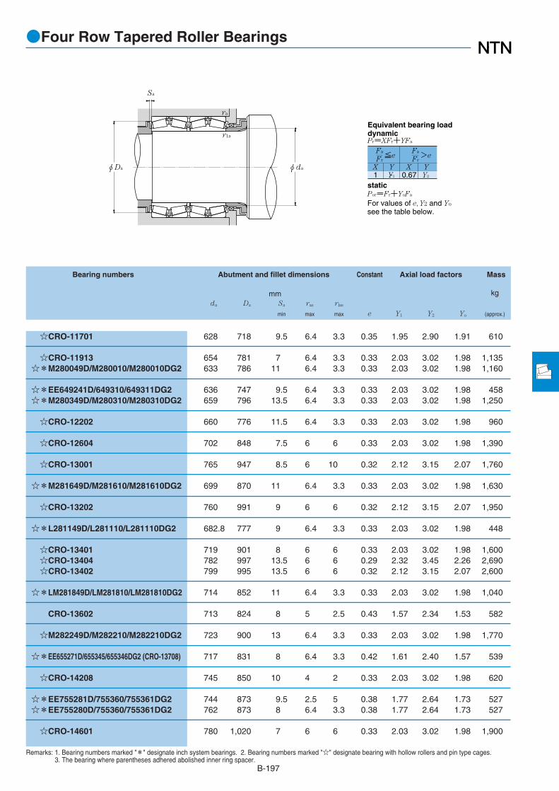
B-197
Remarks: 1. Bearing numbers marked "*" designate inch system bearings. 2. Bearing numbers marked "☆" designate bearing with hollow rollers and pin type cages.3. The bearing where parentheses adhered abolished inner ring spacer.
Bearing numbers Abutment and fillet dimensions Constant Axial load factors Mass
mm kgda Da Sa ras rlas
min max max e Y1 Y2 Yo (approx.)
●Four Row Tapered Roller Bearings
1 Y1 0.67 Y2
Fa
Fr
X Y X Y
≦eFa
Fr>e
Pr=XFr+YFa
Por=Fr+YoFa
For values of e, Y2 and Yo
see the table below.
Equivalent bearing loaddynamic
static
φDa φda
Sa
ra
r1a
☆CRO-11701 628 718 9.5 6.4 3.3 0.35 1.95 2.90 1.91 610
☆CRO-11913 654 781 7 6.4 3.3 0.33 2.03 3.02 1.98 1,135☆*M280049D/M280010/M280010DG2 633 786 11 6.4 3.3 0.33 2.03 3.02 1.98 1,160
☆*EE649241D/649310/649311DG2 636 747 9.5 6.4 3.3 0.33 2.03 3.02 1.98 458☆*M280349D/M280310/M280310DG2 659 796 13.5 6.4 3.3 0.33 2.03 3.02 1.98 1,250
☆CRO-12202 660 776 11.5 6.4 3.3 0.33 2.03 3.02 1.98 960
☆CRO-12604 702 848 7.5 6 6 0.33 2.03 3.02 1.98 1,390
☆CRO-13001 765 947 8.5 6 10 0.32 2.12 3.15 2.07 1,760
☆*M281649D/M281610/M281610DG2 699 870 11 6.4 3.3 0.33 2.03 3.02 1.98 1,630
☆CRO-13202 760 991 9 6 6 0.32 2.12 3.15 2.07 1,950
☆*L281149D/L281110/L281110DG2 682.8 777 9 6.4 3.3 0.33 2.03 3.02 1.98 448
☆CRO-13401 719 901 8 6 6 0.33 2.03 3.02 1.98 1,600☆CRO-13404 782 997 13.5 6 6 0.29 2.32 3.45 2.26 2,690☆CRO-13402 799 995 13.5 6 6 0.32 2.12 3.15 2.07 2,600
☆*LM281849D/LM281810/LM281810DG2 714 852 11 6.4 3.3 0.33 2.03 3.02 1.98 1,040
CRO-13602 713 824 8 5 2.5 0.43 1.57 2.34 1.53 582
☆M282249D/M282210/M282210DG2 723 900 13 6.4 3.3 0.33 2.03 3.02 1.98 1,770
☆*EE655271D/655345/655346DG2 (CRO-13708) 717 831 8 6.4 3.3 0.42 1.61 2.40 1.57 539
☆CRO-14208 745 850 10 4 2 0.33 2.03 3.02 1.98 620
☆*EE755281D/755360/755361DG2 744 873 9.5 2.5 5 0.38 1.77 2.64 1.73 527☆*EE755280D/755360/755361DG2 762 873 8 6.4 3.3 0.38 1.77 2.64 1.73 527
☆CRO-14601 780 1,020 7 6 6 0.33 2.03 3.02 1.98 1,900

●Four Row Tapered Roller Bearings
B-198
Boundary dimensions Basic load ratingsdynamic static dynamic static
mm kN kgf
d D B2 C2 rs min1
rls min1
Cr Cor Cr Cor
1 Minimum allowable dimension for chamfer dimension r or r1.
d 730.250~1,200.150mm
φD φd
C2
B2
r1
r
1,035.050 755.650 755.650 6.4 3.3 18,100 59,500 1,850,000 6,050,000
990.600 605.000 605.000 6.4 3.3 12,600 45,500 1,290,000 4,650,000
1,066.800 723.900 736.600 12.7 4.3 17,700 58,500 1,800,000 5,950,0001,079.500 787.400 787.400 12.7 4.8 19,200 65,000 1,960,000 6,600,000
1,120 820 820 7.5 7 21,000 72,500 2,140,000 7,400,000
1,168.400 844.550 844.550 12.7 4.8 22,300 76,500 2,270,000 7,800,000
1,170 840 840 6 6 21,900 76,500 2,230,000 7,800,000
1,130.300 669.925 669.925 12.7 4.8 15,800 59,500 1,610,000 6,050,0001,219.200 876.300 889.000 12.7 4.8 24,100 83,000 2,450,000 8,450,000
1,270.000 825.500 825.500 12.7 4.8 22,500 80,000 2,300,000 8,150,000
1,360 880 880 7.5 4 27,000 89,000 2,750,000 9,050,000
1,593.850 990.600 990.600 12.7 4.8 33,500 132,000 3,400,000 13,500,000
730.250
749.300
762.000
800
825.500
840
863.600
938.212
950
1,200.150

B-199
Remarks: 1. Bearing numbers marked "*" designate inch system bearings. 2. Bearing numbers marked "☆" designate bearing with hollow rollers and pin type cages.3. The bearing where parentheses adhered abolished inner ring spacer.
Bearing numbers Abutment and fillet dimensions Constant Axial load factors Mass
mm kgda Da Sa ras rlas
min max max e Y1 Y2 Yo (approx.)
●Four Row Tapered Roller Bearings
1 Y1 0.67 Y2
Fa
Fr
X Y X Y
≦eFa
Fr>e
Pr=XFr+YFa
Por=Fr+YoFa
For values of e, Y2 and Yo
see the table below.
Equivalent bearing loaddynamic
static
φDa φda
Sa
ra
r1a
☆*M283449D/M283410/M283410D 774 966 13 6.4 3.3 0.33 2.03 3.02 1.98 2,210
☆*LM283649D/LM283610/LM283610DG2 786 936 10.5 6.4 3.3 0.33 2.03 3.02 1.98 1,250
☆*M284148D/M284111/M284110DG2 840 985 3.5 12.7 4.3 0.33 2.03 3.02 1.98 2,220☆*M284249D/M284210/M284210DG2 810 1,005 13 12.7 4.8 0.33 2.03 3.02 1.98 2,480
☆CRO-16001 858 1,052 10 6 6 0.33 2.03 3.02 1.98 3,960
☆*M285848D/M285810/M285810DG2 879 1,085 13 12.7 4.8 0.33 2.03 3.02 1.98 3,010
☆CRO-16803 897 1,099 12 5 5 0.33 2.03 3.02 1.98 3,970
☆*LM286249D/LM286210/LM286210DG2 906 1,065 11 12.7 4.8 0.33 2.03 3.02 1.98 1,950☆*EE547341D/547480/547481DG2 (CRO-17301) 918 1,135 6.5 12.7 4.8 0.33 2.03 3.02 1.98 3,640
☆*LM287649D/LM287610/LM287610DG2 990 1,190 10 12.7 4.8 0.33 2.03 3.02 1.98 4,100
☆CRO-19001 1,030 1,278 12 6 3 0.35 1.95 2.90 1.91 4,100
☆*LM288949D/LM288910/LM288910DG2 1,260 1,500 13 12.7 4.8 0.33 2.03 3.02 1.98 6,130

B-200
●Sealed Four Row Tapered Roller Bearings
Boundary dimensions Basic load ratings Bearingdynamic static dynamic static numbers
mm kN kgf
d D B2 C2 rs min1
rls min1
Cr Cor Cr Cor
d 140~711.200mm
φD φd
B2
r1
r
C2
1 Minimum allowable dimension for chamfer dimension r or r1.Remarks: 1. The marked "*" bearings are inch system sizes.
198 174 174 2 1.5 595 1,470 60,500 150,000 CRO-2810LL198 174 174 2 1.5 615 1,510 63,000 154,000 CRO-2812LL
282 206 206 2.5 2.5 950 2,450 97,000 250,000 CRO-4022LL330.2 263.525 269.875 3.3 1.5 1,770 4,000 180,000 405,000 *CRO-4303LL295 315 315 2.5 1 1,270 3,850 130,000 395,000 CRO-4424LL310 280 280 2.5 1 1,590 4,100 162,000 420,000 CRO-4427LL320 290 290 3 2.7 1,780 4,850 181,000 495,000 CRO-4436LL338 248 248 3 3 1,590 4,200 162,000 430,000 CRO-4811LL338 340 340 2.5 1 2,040 6,000 208,000 610,000 CRO-4817LL345 310 310 3 1 2,070 5,950 211,000 610,000 CRO-4906LL365 270 270 3 2.5 1,920 4,750 196,000 485,000 CRO-5015LL358.775 269.875 269.875 3.3 1.5 1,940 4,900 198,000 500,000 *CRO-5117LL358.775 269.875 269.875 3.3 3.3 1,850 4,750 188,000 485,000 *CRO-5116LL365 339 339 4 1 2,250 5,950 229,000 610,000 CRO-5224LL422.275 314.325 317.5 3.3 4.8 2,680 5,950 274,000 606,000 *CRO-5227LL393.7 269.875 269.875 6.4 1.5 2,000 4,950 204,000 505,000 *CRO-5652LL380 290 290 3 1 2,060 5,750 210,000 585,000 CRO-5660LL395 290 290 4 1.5 2,120 5,450 216,000 560,000 CRO-5665LL395 340 340 2.5 3.2 2,590 7,150 264,000 730,000 CRO-5664LL410 268 268 6.4 2.2 2,140 5,000 219,000 505,000 CRO-5639LL400 340 340 4 1 2,560 7,650 261,000 780,000 CRO-5709LL400 346 346 4 3.1 2,560 7,650 261,000 780,000 CRO-5814LL400 254 254 4 5 1,920 5,300 196,000 540,000 CRO-6038LL420 310 310 4 3.2 2,510 6,850 256,000 695,000 CRO-6042LL430 295 305 5 1 2,150 5,550 219,000 565,000 CRO-6031LL438.048 280.99 279.4 3.7 2.8 2,250 5,450 229,000 555,000 *CRO-6143LL
430 310 310 4 1.5 2,340 6,600 239,000 670,000 CRO-6220LL430 350 350 2.5 3.2 2,820 7,950 288,000 815,000 CRO-6222LL480 360 360 4 2 3,600 8,850 370,000 900,000 CRO-6426LL
457.098 254 254 3.3 1.5 2,060 5,500 210,000 560,000 *CRO-6930LL457.098 254 254 3.3 0.6 1,900 5,050 194,000 515,000 *CRO-6920LL457.098 299 299 3.3 1.5 2,470 7,100 252,000 725,000 *CRO-6936LL490 316 316 4 2.3 2,520 6,600 257,000 675,000 CRO-7109LL480 375 375 3 2.8 3,400 10,200 345,000 1,040,000 CRO-7226LL546 400 400 5 1.5 3,850 11,900 390,000 1,210,000 CRO-8204LL620 395 320 6 6 4,550 11,800 465,000 1,200,000 CRO-8412LL
590 480 480 6 1.5 4,550 13,900 465,000 1,420,000 CRO-8830LL620 454 454 6 1.5 5,800 16,600 595,000 1,700,000 CRO-8832LL596.9 276.225 279.4 3.3 1.5 2,540 6,800 259,000 695,000 *CRO-9107LL679.45 495.3 495.3 6.4 0.6 6,450 18,400 660,000 1,870,000 *CRO-9610LL
615.95 330.2 330.2 6.4 3.3 3,200 9,650 330,000 985,000 *CRO-9725LL715 590 590 6 4 8,200 26,900 835,000 2,740,000 CRO-10607LL844.55 615.95 615.95 6.4 3.0 10,600 32,000 1,080,000 3,250,000 *CRO-11919LL914.4 387.35 387.35 6.4 3.3 6,300 19,600 645,000 2,000,000 *CRO-14214LL914.4 410 410 5 2.5 6,400 20,700 655,000 2,110,000 *CRO-14209LL
140
200216.103
220
240
245250
254
260260.35279.4
280
285290
300
304.648
310
320
343.052
355360410420
440
457.2479.425482.6530595.312
711.2

B-201
Constant Axial load factors Mass
kg
e Y1 Y2 Yo (approx.)
●Sealed Four Row Tapered Roller Bearings
0.40 1.68 2.50 1.64 160.47 1.43 2.12 1.40 15.5
0.33 2.03 3.02 1.98 39
0.55 1.23 1.82 1.20 78.2
0.37 1.80 2.69 1.76 57.50.33 2.03 3.02 1.98 63.50.39 1.74 2.59 1.70 77
0.43 1.57 2.34 1.53 67.80.40 1.68 2.50 1.64 94.4
0.40 1.68 2.50 1.64 90.5
0.40 1.68 2.50 1.64 90
0.40 1.68 2.50 1.64 830.55 1.24 1.84 1.21 81.7
0.40 1.68 2.50 1.64 103
0.55 1.24 1.84 1.21 177
0.47 1.43 2.12 1.40 96.4
0.33 2.03 3.02 1.98 900.33 2.07 3.09 2.03 1080.40 1.68 2.50 1.64 1260.33 2.07 3.09 2.03 116
0.40 1.68 2.50 1.64 134
0.40 1.68 2.50 1.64 129
0.28 2.43 3.61 2.37 84.60.40 1.68 2.50 1.64 1280.33 2.03 3.02 1.98 136
0.47 1.43 2.12 1.40 136
0.40 1.68 2.50 1.64 1330.40 1.68 2.50 1.64 150
0.47 1.43 2.12 1.40 228
0.47 1.43 2.12 1.40 1050.33 2.03 3.02 1.98 1070.43 1.57 2.34 1.53 130
0.33 2.03 3.02 1.98 159
0.33 2.03 3.02 1.98 180
0.33 2.03 3.02 1.98 253
0.37 1.80 2.69 1.76 384
0.33 2.03 3.02 1.98 3580.33 2.03 3.02 1.98 426
0.47 1.43 2.12 1.40 192
0.33 2.03 3.02 1.98 565
0.33 2.03 3.02 1.98 225
0.32 2.12 3.15 2.07 700
0.33 2.03 3.02 1.98 1130
0.38 1.78 2.65 1.74 6160.38 1.77 2.64 1.73 596

Spherical Roller bearings

●Spherical Roller Bearings
1. Type, Structure and Characteristics
The barrel shaped spherical rolling elements of a self-aligning bearing track along two rows of raceway grooves inthe inner ring. The center of the outer ring’s raceway alignswith the center of the bearing. The self-aligning featureaccommodates errors in housing assembly andmisalignments between the inner and outer rings caused bybent shafts. The bearings have a large load capacity and aresuitable for applications with vibration and impact loads.
B-203
Model Standard (Model B) Model C Model 213
Structure
Bearing Series
Roller
Roller guide type
Cage type
Bearings except Model C 24024~24038213's bore should bemore than 55mm.
A symmetrical roller Symmetrical roller A symmetrical roller
Guided by the inner rib which isunited with the inner ring.
By the guide ring locatedbetween two rows of rollers.
By the guide ring locatedbetween the rollers on theouter ring raceway.
Pressed cageMachined cage
Pressed cage Machined cage
Table 1 Model of Self-Aligning Roller Bearings
In addition to a cylindrical shaft bore, the bearings areavailable with a tapered shaft bore. The tapered borebearings can be shaft mounted using an adapter orremovable sleeves. Table 1 shows the types of the self-aligning roller bearings. Please consult with NTNEngineering for the special product (do part number startswith 2p)
1.2 Lubrication holes and grooves
Holes and grooves to supply lubricant are provided onself-aligning roller bearings with outside diameters greaterthan 320mm. If required, lubrication holes and grooves canbe manufactured for bearings with ODs smaller than320mm. Consult NTN Engineering for further details andadd the supplemental code D1 to the part number. Table 2shows the dimensions for lubrication holes and grooves. Thenumber of lubrication holes are shown in Table 3.
When a knock pin for lubricant retention is necessary,please contact NTN Engineering.
Unit mm
80100120160200315
Nominal bearing width
over incl
Oil groove widthWo
Oil hole diado
Oil groove depthh Width series
4Width series
1, 2, 3
100120160200315-
141620273342
81012162025
2.53.03.55.06.07.0
2.02.53.03.55.06.5
Table 2 Lubrication hole and groove dimensions
Table 3 Lubrication hole number
Nominal bearingoutside dia. mm
- 320
1,010
3201,010-
48
12
over incl
Hole numberZo

●Spherical Roller Bearings
B-204
6. Assembly of Tapered Hole Roller Bearings
Tapered hole spherical roller bearings use themeasurement method as shown in Fig.1. A suitabletightening rate can be achieved by pushing the bearingtoward the axial direction until it reaches the reduction rateof the radial internal clearance or pushing rate of axialdirection. When heavy and high speed loads are applied, orwhen it is necessary to keep a higher tightening rate as thetemperature difference between the inner and outer ringsrises, be sure to have the maximum reduction rate of radialinternal clearance or the pushing rate of the axial direction,as shown in Table 4, by using a bearing with a radialinternal clearance of more than C3. The clearance aftermounting in this case should be larger than the minimumclearance after mounting as shown in Table 4.
Nominal bearing bore
over incl
80100120
140160180
200225250
280315355
400450500
560630710
800900
1,0001,120
Unit:mm
d
Reduction rate of
radial internal clearance
min max
Pushing rate of axial direction
taper 1/12
maxmin
taper 1/30
min max
Minimum residual internal clearance
CN C4C3
100120140
160180200
225250280
315355400
450500560
630710800
9001,0001,1201,250
0.0450.05 0.065
0.0750.08 0.09
0.1 0.11 0.12
0.13 0.15 0.17
0.2 0.21 0.24
0.26 0.3 0.34
0.37 0.41 0.45 0.49
0.0550.06 0.075
0.09 0.1 0.11
0.12 0.13 0.15
0.16 0.18 0.21
0.24 0.26 0.3
0.33 0.37 0.43
0.47 0.53 0.58 0.63
0.70.751.1
1.21.31.4
1.61.71.9
2 2.42.6
3.13.33.7
4 4.65.3
5.76.36.87.4
0.80.91.2
1.41.61.7
1.92 2.4
2.52.83.3
3.74 4.6
5.15.76.7
7.38.28.79.4
1.751.9 2.75
3 3.253.5
4 4.254.75
5 6 6.5
7.758.259.25
10 11.5 13.3
14.3 15.8 17 18.5
2.252.253
3.754 4.25
4.755 6
6.257 8.25
9.2510 11.5
12.5 14.5 16.5
18.5 20.5 22.5 24.5
0.0350.05 0.055
0.0550.06 0.07
0.08 0.09 0.1
0.11 0.12 0.13
0.13 0.16 0.17
0.2 0.21 0.23
0.27 0.3 0.32 0.34
0.05 0.0650.08
0.09 0.1 0.1
0.12 0.13 0.14
0.15 0.17 0.19
0.2 0.23 0.25
0.29 0.31 0.35
0.39 0.43 0.48 0.54
0.08 0.1 0.11
0.13 0.15 0.16
0.18 0.2 0.22
0.24 0.26 0.29
0.31 0.35 0.36
0.41 0.45 0.51
0.57 0.64 0.7 0.77
Table 4 Assembly of tapered hole spherical roller bearings
Fig.1 Measurement method of spherical roller bearing internal clearance
Clearance gauge
2. Dimensional Accuracy/Rotation Accuracy
Refer to Table 3.3 (Page A-12)
3. Recommended Fitting
Refer to Table 4.2 (Page A-24)
4. Bearing Internal Clearance
Refer to Table 5.10 (Page A-36)
5. Allowable aligning angle
These bearings have a self-aligning function, and theirallowable aligning angle varies depending on the dimensionseries and load conditions, but are mostly described asfollows.
Normal load (Equivalent load to 0.09 Cr) ⋯ 0.009rad (0.5°)Light load ⋯⋯⋯⋯⋯⋯⋯⋯⋯⋯⋯⋯⋯ 0.035rad (2°)

B-205
●Spherical Roller Bearings
7. General Operating Cautions
Pressed cages or machined cages are standarddepending on the bearing type and dimensions. However, astandard cage may not be used under high speedspecifications or in conditions under severe vibration orimpact.
When bearings are operated under small loads (about Fr
≦ 0.04Cor), or under axial loads only, prevent rollingelements from smearing by operating in conditions whereFa/Fr≦ 2e. (Refer to the dimension table for the value of“e.”) This is most apparent when using large size sphericalroller bearings due to the large roller and cage mass. Pleaseconsult NTN Engineering for further details.

B-206
●Spherical Roller Bearings
Boundary dimensions Basic load ratings Bearing numbers Abutment anddynamic static dynamic static fillet dimensions
mm kN kgf mmCylindrical tapered2
da Da ras
d D B rs min1
Cr Cor Cr Cor bore bore min max max
1 Smallest allowable dimension for chamfer dimension r.2 Bearings appended with "K" have a tapered bore ratio of 1:12; bearings appended with "K30" have a tapered bore ratio of 1:30.Remarks: 1. Bearing numbers marked "☆" are C type.
d 100~140mm
Cylindrical bore Tapered boretaper 1:12
r
φd
B
φdφD
r
165 52 2 310 470 31,500 47,500 23120B 23120BK 110 155 2170 65 2 380 590 38,500 60,000 2P2009 2P2009K 110 160 2170 65 2 405 640 41,500 65,500 ☆2P2014 2P2014K 110 160 2180 46 2.1 315 415 32,000 42,500 22220B 22220BK 112 168 2180 60.3 2.1 405 580 41,500 59,000 23220B 23220BK 112 168 2215 47 3 370 465 37,500 47,500 21320 21320K 114 201 2.5215 73 3 605 755 61,500 77,000 22320B 22320BK 114 201 2.5
170 45 2 282 455 28,800 46,500 23022B 23022BK 120 160 2180 56 2 370 580 37,500 59,500 23122B 23122BK 120 170 2180 69 2 450 755 46,000 77,000 24122B 24122BK30 120 170 2200 53 2.1 410 570 42,000 58,000 22222B 22222BK 122 188 2200 69.8 2.1 515 760 52,500 77,500 23222B 23222BK 122 188 2240 50 3 495 615 50,500 62,500 21322 21322K 124 226 2.5240 80 3 745 930 76,000 95,000 22322B 22322BK 124 226 2.5
180 46 2 296 495 30,000 50,500 23024B 23024BK 130 170 2180 60 2 390 670 39,500 68,500 24024B 24024BK30 130 170 2180 60 2 395 695 40,000 71,000 ☆24024C 24024CK30 130 170 2180 69 2 415 785 42,500 80,000 ☆2P2416 2P2416K 130 170 2200 62 2 455 705 46,500 71,500 23124B 23124BK 130 190 2200 80 2 575 945 58,500 96,500 24124B 24124BK30 130 190 2215 58 2.1 485 700 49,500 71,500 22224B 22224BK 132 203 2215 76 2.1 585 880 59,500 89,500 23224B 23224BK 132 203 2260 86 3 880 1,120 89,500 114,000 22324B 22324BK 134 246 2.5
200 52 2 375 620 38,500 63,500 23026B 23026BK 140 190 2200 69 2 505 895 51,500 91,000 24026B 24026BK30 140 190 2200 69 2 490 860 50,000 87,500 ☆24026C 24026CK30 140 190 2210 64 2 495 795 50,500 81,000 23126B 23126BK 140 200 2210 80 2 585 995 60,000 102,000 24126B 24126BK30 140 200 2230 64 3 570 790 58,000 80,500 22226B 22226BK 144 216 2.5230 80 3 685 1,060 70,000 108,000 23226B 23226BK 144 216 2.5280 93 4 1,000 1,290 102,000 131,000 22326B 22326BK 148 262 3
218 80 1.1 605 1,050 61,500 106,000 2P2803 2P2803K 146 211 1
210 53 2 405 690 41,000 70,500 23028B 23028BK 150 200 2210 69 2 510 945 52,000 96,500 24028B 24028BK30 150 200 2
100
110
120
130
139.734
140

B-207
●Spherical Roller Bearings
1 Y1 0.67 Y2
Fa
Fr
X Y X Y
≦eFa
Fr>e
Pr=XFr+YFa
Por=Fr+Yo Fa
For values of e, Y1, Y2 and Yosee the table below.
Equivalent bearing loaddynamic
static
ra
ra
φdaφDa
Constant Axial load factors Mass (approx.)
kgCylindrical tapered
e Y1 Y2 Yo bore bore
0.32 2.12 3.15 2.07 4.3 4.160.38 1.78 2.65 1.74 5.84 5.620.38 1.75 2.61 1.72 5.91 5.690.26 2.55 3.80 2.49 4.95 4.840.34 1.98 2.94 1.93 6.47 6.280.22 3.01 4.48 2.94 8.89 8.780.37 1.80 2.69 1.76 12.4 12.1
0.26 2.59 3.85 2.53 3.71 3.580.31 2.17 3.24 2.13 5.4 5.220.38 1.76 2.63 1.73 7.07 6.960.27 2.51 3.74 2.46 7.2 7.040.35 1.91 2.84 1.86 9.71 9.430.21 3.20 4.77 3.13 11.2 11.10.36 1.87 2.79 1.83 17.1 16.7
0.25 2.69 4.01 2.63 4.05 3.90.33 2.06 3.07 2.02 5.48 5.390.32 2.12 3.15 2.07 5.48 4.910.35 1.95 2.90 1.91 5.95 5.650.31 2.17 3.24 2.13 7.7 7.460.40 1.68 2.50 1.64 10.3 10.10.27 2.47 3.68 2.42 9.1 8.890.36 1.89 2.82 1.85 12.1 11.70.37 1.80 2.69 1.76 21.5 21
0.26 2.63 3.92 2.57 5.9 5.690.34 1.98 2.95 1.94 8.08 7.950.32 2.12 3.15 2.07 7.91 7.780.30 2.23 3.32 2.18 8.47 8.20.38 1.78 2.65 1.74 11 10.80.28 2.39 3.56 2.33 11.2 10.90.35 1.92 2.86 1.88 14.3 13.90.37 1.81 2.69 1.77 26.8 26.2
0.35 1.91 2.84 1.86 10.8 10.3
0.25 2.73 4.06 2.67 6.35 6.120.32 2.09 3.12 2.05 8.57 8.43

B-208
●Spherical Roller Bearings
Boundary dimensions Basic load ratings Bearing numbers Abutment anddynamic static dynamic static fillet dimensions
mm kN kgf mmCylindrical tapered2
da Da ras
d D B rs min1
Cr Cor Cr Cor bore bore min max max
1 Smallest allowable dimension for chamfer dimension r.2 Bearings appended with "K" have a tapered bore ratio of 1:12; bearings appended with "K30" have a tapered bore ratio of 1:30.Remarks: 1. Bearing numbers marked "☆" are C type.
d 140~180mm
Cylindrical bore Tapered boretaper 1:12
r
φd
B
φdφD
r
210 69 2 520 940 53,000 95,500 ☆24028C 24028CK30 150 200 2225 68 2.1 540 895 55,000 91,000 23128B 23128BK 152 213 2225 85 2.1 670 1,150 68,500 117,000 24128B 24128BK30 152 213 2250 68 3 685 975 70,000 99,500 22228B 22228BK 154 236 2.5250 88 3 805 1,270 82,000 129,000 23228B 23228BK 154 236 2.5300 102 4 1,130 1,460 115,000 149,000 22328B 22328BK 158 282 3
225 56 2.1 445 775 45,500 79,000 23030B 23030BK 162 213 2225 75 2.1 585 1,060 59,500 108,000 24030B 24030BK30 162 213 2225 75 2.1 600 1,090 61,000 111,000 ☆24030C 24030CK30 162 213 2250 80 2.1 730 1,190 74,500 121,000 23130B 23130BK 162 238 2250 100 2.1 885 1,520 90,500 155,000 24130B 24130BK30 162 238 2270 73 3 775 1,160 79,000 119,000 22230B 22230BK 164 256 2.5270 96 3 935 1,460 95,000 149,000 23230B 23230BK 164 256 2.5320 108 4 1,270 1,750 130,000 179,000 22330B 22330BK 168 302 3
220 45 2 320 610 33,000 62,500 23932 23932K 170 210 2240 60 2.1 505 885 51,500 90,000 23032B 23032BK 172 228 2240 80 2.1 650 1,200 66,500 122,000 24032B 24032BK30 172 228 2240 80 2.1 665 1,250 67,500 127,000 ☆24032C 24032CK30 172 228 2270 86 2.1 840 1,370 85,500 140,000 23132B 23132BK 172 258 2270 109 2.1 1,040 1,780 106,000 181,000 24132B 24132BK30 172 258 2290 80 3 870 1,290 88,500 132,000 22232B 22232BK 174 276 2.5290 104 3 1,050 1,660 107,000 170,000 23232B 23232BK 174 276 2.5340 114 4 1,410 1,990 144,000 203,000 22332B 22332BK 178 322 3
230 45 2 330 650 34,000 66,000 23934 23934K 180 220 2260 67 2.1 630 1,080 64,000 110,000 23034B 23034BK 182 248 2260 90 2.1 800 1,470 81,500 150,000 24034B 24034BK30 182 248 2260 90 2.1 815 1,500 83,000 153,000 ☆24034C 24034CK30 182 248 2280 88 2.1 885 1,490 90,500 152,000 23134B 23134BK 182 268 2280 109 2.1 1,080 1,880 110,000 191,000 24134B 24134BK30 182 268 2310 86 4 1,000 1,520 102,000 155,000 22234B 22234BK 188 292 3310 110 4 1,180 1,960 120,000 200,000 23234B 23234BK 188 292 3360 120 4 1,540 2,180 157,000 223,000 22334B 22334BK 188 342 3
250 52 2 440 835 45,000 85,000 23936 23936K 190 240 2280 74 2.1 740 1,290 75,500 132,000 23036B 23036BK 192 268 2280 100 2.1 965 1,770 98,500 181,000 24036B 24036BK30 192 268 2
140
150
160
170
180

B-209
●Spherical Roller Bearings
1 Y1 0.67 Y2
Fa
Fr
X Y X Y
≦eFa
Fr>e
Pr=XFr+YFa
Por=Fr+Yo Fa
For values of e, Y1, Y2 and Yosee the table below.
Equivalent bearing loaddynamic
static
ra
ra
φdaφDa
Constant Axial load factors Mass (approx.)
kgCylindrical tapered
e Y1 Y2 Yo bore bore
0.30 2.23 3.32 2.18 8.48 7.660.30 2.25 3.35 2.20 10.2 9.860.38 1.80 2.68 1.76 13.3 13.10.28 2.39 3.55 2.33 14 13.70.36 1.90 2.83 1.86 18.8 18.20.37 1.80 2.69 1.76 33.8 33
0.24 2.76 4.11 2.70 7.73 7.450.33 2.06 3.07 2.02 10.7 10.50.30 2.25 3.34 2.20 10.5 10.30.32 2.11 3.15 2.06 15.6 15.10.40 1.69 2.51 1.65 20.2 200.27 2.46 3.66 2.40 18.1 17.70.36 1.88 2.79 1.83 24.1 23.40.35 1.92 2.86 1.88 42.7 41.8
0.18 3.69 5.49 3.61 5.5 5.330.25 2.74 4.09 2.68 9.42 9.090.32 2.10 3.13 2.06 13 12.80.31 2.18 3.24 2.13 12 11.80.32 2.11 3.15 2.07 19.8 19.20.40 1.67 2.48 1.63 26 25.60.28 2.42 3.60 2.37 22.7 22.20.36 1.86 2.77 1.82 30 29.10.35 1.94 2.89 1.90 50.8 49.7
0.17 3.91 5.83 3.83 5.8 5.620.25 2.66 3.96 2.60 12.7 12.30.34 1.98 2.95 1.94 17.7 17.40.31 2.16 3.22 2.12 17.4 17.10.31 2.15 3.21 2.11 21.5 20.80.39 1.74 2.59 1.70 27.2 26.80.28 2.39 3.56 2.34 28 27.30.36 1.87 2.79 1.83 36.8 35.70.34 1.96 2.91 1.91 59.8 58.5
0.19 3.52 5.25 3.45 8.21 7.950.26 2.59 3.85 2.53 16.7 16.10.35 1.91 2.85 1.87 23.3 22.9

B-210
●Spherical Roller Bearings
Boundary dimensions Basic load ratings Bearing numbers Abutment anddynamic static dynamic static fillet dimensions
mm kN kgf mmCylindrical tapered2
da Da ras
d D B rs min1
Cr Cor Cr Cor bore bore min max max
1 Smallest allowable dimension for chamfer dimension r.2 Bearings appended with "K" have a tapered bore ratio of 1:12; bearings appended with "K30" have a tapered bore ratio of 1:30.Remarks: 1. Bearing numbers marked "☆" are C type.
d 180~240mm
Cylindrical bore Tapered boretaper 1:12
r
φd
B
φdφD
r
280 100 2.1 965 1,770 98,500 181,000 ☆24036C 24036CK30 192 268 2290 110 2.1 1,050 1,890 107,000 193,000 2P3604 2P3604K 192 278 2300 96 3 1,030 1,730 105,000 176,000 23136B 23136BK 194 286 2.5300 118 3 1,250 2,210 127,000 225,000 24136B 24136BK30 194 286 2.5320 86 4 1,040 1,610 106,000 164,000 22236B 22236BK 198 302 3320 112 4 1,230 2,000 125,000 204,000 23236B 23236BK 198 302 3380 126 4 1,740 2,560 177,000 261,000 22336B 22336BK 198 362 3
260 52 2 460 890 47,000 91,000 23938 23938K 200 250 2290 75 2.1 755 1,350 77,000 138,000 23038B 23038BK 202 278 2290 100 2.1 995 1,850 102,000 188,000 24038B 24038BK30 202 278 2290 100 2.1 970 1,820 98,500 186,000 ☆24038C 24038CK30 202 278 2320 104 3 1,190 2,020 122,000 206,000 23138B 23138BK 204 306 2.5320 128 3 1,420 2,480 144,000 253,000 24138B 24138BK30 204 306 2.5340 92 4 1,160 1,810 118,000 185,000 22238B 22238BK 208 322 3340 120 4 1,400 2,330 143,000 237,000 23238B 23238BK 208 322 3400 132 5 1,870 2,790 191,000 284,000 22338B 22338BK 212 378 4
280 60 2.1 545 1,100 56,000 112,000 23940 23940K 212 268 2310 82 2.1 915 1,620 93,000 165,000 23040B 23040BK 212 298 2310 109 2.1 1,160 2,140 118,000 219,000 24040B 24040BK30 212 298 2340 112 3 1,350 2,270 137,000 231,000 23140B 23140BK 214 326 2.5340 140 3 1,630 2,900 166,000 295,000 24140B 24140BK30 214 326 2.5360 98 4 1,310 2,010 134,000 205,000 22240B 22240BK 218 342 3360 128 4 1,610 2,640 165,000 269,000 23240B 23240BK 218 342 3420 138 5 2,040 3,050 208,000 310,000 22340B 22340BK 222 398 4
300 60 2.1 565 1,170 57,500 119,000 23944 23944K 232 288 2340 90 3 1,060 1,920 108,000 195,000 23044B 23044BK 234 326 2.5340 118 3 1,350 2,570 138,000 262,000 24044B 24044BK30 234 326 2.5370 120 4 1,540 2,670 157,000 272,000 23144B 23144BK 238 352 3370 150 4 1,880 3,400 192,000 345,000 24144B 24144BK30 238 352 3400 108 4 1,580 2,460 161,000 251,000 22244B 22244BK 238 382 3400 144 4 2,010 3,350 205,000 340,000 23244B 23244BK 238 382 3400 150 4 2,040 3,400 208,000 345,000 2P4401 2P4401K30 238 382 3460 145 5 2,350 3,500 240,000 360,000 22344B 22344BK 242 438 4
320 60 2.1 565 1,190 58,000 121,000 23948 23948K 252 308 2360 92 3 1,130 2,140 116,000 219,000 23048B 23048BK 254 346 2.5
180
190
200
220
240

B-211
●Spherical Roller Bearings
1 Y1 0.67 Y2
Fa
Fr
X Y X Y
≦eFa
Fr>e
Pr=XFr+YFa
Por=Fr+Yo Fa
For values of e, Y1, Y2 and Yosee the table below.
Equivalent bearing loaddynamic
static
ra
ra
φdaφDa
Constant Axial load factors Mass (approx.)
kgCylindrical tapered
e Y1 Y2 Yo bore bore
0.33 2.04 3.04 2.00 23 22.60.37 1.82 2.70 1.78 27.5 26.30.32 2.11 3.15 2.07 25.1 24.20.39 1.72 2.56 1.68 34.3 33.80.27 2.49 3.70 2.43 29.3 28.60.35 1.91 2.84 1.86 39 37.80.34 1.97 2.93 1.92 70 68.5
0.18 3.81 5.67 3.73 8.6 8.340.26 2.65 3.94 2.59 17.7 17.10.33 2.03 3.02 1.98 24.3 23.90.31 2.16 3.22 2.12 23 22.60.33 2.07 3.09 2.03 35.3 34.20.40 1.69 2.51 1.65 42.8 42.20.27 2.47 3.68 2.42 36.6 35.80.36 1.89 2.82 1.85 47.6 46.20.34 1.97 2.94 1.93 81 79.3
0.17 3.91 5.82 3.82 12.1 11.70.26 2.59 3.85 2.53 22.7 21.90.35 1.94 2.89 1.90 31 30.50.33 2.05 3.05 2.00 43.3 420.41 1.64 2.44 1.60 53.4 52.60.28 2.45 3.64 2.39 44 430.36 1.88 2.79 1.83 57.2 55.50.34 1.98 2.95 1.94 93.2 91.2
0.19 3.62 5.39 3.54 13.1 12.70.26 2.59 3.85 2.53 29.9 28.80.34 1.97 2.94 1.93 40.2 39.60.33 2.07 3.09 2.03 53.3 51.60.41 1.66 2.47 1.62 67 660.27 2.46 3.66 2.40 60.4 59.10.36 1.85 2.76 1.81 80 77.60.41 1.64 2.44 1.61 81.9 80.80.33 2.06 3.07 2.02 117 115
0.16 4.13 6.15 4.04 14 13.60.25 2.69 4.01 2.63 33.4 32.2

B-212
●Spherical Roller Bearings
Boundary dimensions Basic load ratings Bearing numbers Abutment anddynamic static dynamic static fillet dimensions
mm kN kgf mmCylindrical tapered2
da Da ras
d D B rs min1
Cr Cor Cr Cor bore bore min max max
1 Smallest allowable dimension for chamfer dimension r.2 Bearings appended with "K" have a tapered bore ratio of 1:12; bearings appended with "K30" have a tapered bore ratio of 1:30.
d 240~300mm
Cylindrical bore Tapered boretaper 1:12
r
φd
B
φdφD
r
360 118 3 1,410 2,770 144,000 282,000 24048B 24048BK30 254 346 2.5400 128 4 1,730 3,050 177,000 310,000 23148B 23148BK 258 382 3400 160 4 2,110 3,800 215,000 390,000 24148B 24148BK30 258 382 3440 120 4 1,940 3,100 198,000 315,000 22248B 22248BK 258 422 3440 160 4 2,430 4,100 247,000 420,000 23248B 23248BK 258 422 3500 155 5 2,720 4,100 278,000 420,000 22348B 22348BK 262 478 4
400.05 120.65 4 1,590 2,780 162,000 283,000 2P5002 2P5002K 266 382 3
360 70 2.1 805 1,590 82,000 163,000 2P5203 2P5203K 272 348 2360 75 2.1 760 1,580 77,500 161,000 23952 23952K 272 348 2400 104 4 1,420 2,620 144,000 267,000 23052B 23052BK 278 382 3400 140 4 1,830 3,550 186,000 365,000 24052B 24052BK30 278 382 3440 144 4 2,140 3,850 219,000 395,000 23152B 23152BK 278 422 3440 180 4 2,510 4,600 256,000 470,000 24152B 24152BK30 278 422 3480 130 5 2,230 3,600 228,000 365,000 22252B 22252BK 282 458 4480 174 5 2,760 4,700 281,000 480,000 23252B 23252BK 282 458 4540 165 6 3,100 4,750 320,000 485,000 22352B 22352BK 288 512 5
350 52 2 525 1,220 54,000 125,000 23856 23856K 290 340 2380 75 2.1 830 1,750 84,500 179,000 23956 23956K 292 368 2420 106 4 1,510 2,920 154,000 297,000 23056B 23056BK 298 402 3420 140 4 1,950 3,950 199,000 405,000 24056B 24056BK30 298 402 3440 160 4 2,180 4,250 222,000 435,000 2P5604 2P5604K 298 422 3460 146 5 2,300 4,250 234,000 435,000 23156B 23156BK 302 438 4460 180 5 2,730 5,200 278,000 530,000 24156B 24156BK30 302 438 4500 130 5 2,310 3,800 236,000 390,000 22256B 22256BK 302 478 4500 176 5 2,930 5,150 298,000 525,000 23256B 23256BK 302 478 4580 175 6 3,500 5,350 360,000 545,000 22356B 22356BK 308 552 5
430 110 4 1,380 2,860 141,000 291,000 2P5802 2P5802K 308 412 3
420 90 3 1,110 2,320 113,000 237,000 23960 23960K 314 406 2.5460 118 4 1,890 3,550 193,000 365,000 23060B 23060BK 318 442 3460 160 4 2,450 4,950 250,000 505,000 24060B 24060BK30 318 442 3500 160 5 2,750 5,000 280,000 510,000 23160B 23160BK 322 478 4500 200 5 3,300 6,400 340,000 650,000 24160B 24160BK30 322 478 4540 140 5 2,670 4,350 272,000 440,000 22260B 22260BK 322 518 4540 192 5 3,450 6,000 355,000 615,000 23260B 23260BK 322 518 4
240
247.65
260
280
290
300

B-213
●Spherical Roller Bearings
1 Y1 0.67 Y2
Fa
Fr
X Y X Y
≦eFa
Fr>e
Pr=XFr+YFa
Por=Fr+Yo Fa
For values of e, Y1, Y2 and Yosee the table below.
Equivalent bearing loaddynamic
static
ra
ra
φdaφDa
Constant Axial load factors Mass (approx.)
kgCylindrical tapered
e Y1 Y2 Yo bore bore
0.32 2.09 3.12 2.05 43 42.30.32 2.11 3.15 2.07 65.8 63.80.40 1.69 2.51 1.65 82.2 80.90.28 2.43 3.62 2.38 81.7 800.37 1.83 2.72 1.79 108 1050.32 2.10 3.13 2.06 148 145
0.31 2.18 3.24 2.13 58.2 56.3
0.18 3.76 5.60 3.67 21.6 210.19 3.53 5.26 3.45 24 23.30.26 2.63 3.92 2.57 48.5 46.80.34 1.96 2.91 1.91 65.2 64.10.33 2.05 3.06 2.01 91.4 88.60.41 1.63 2.43 1.60 114 1120.28 2.45 3.64 2.39 106 1040.37 1.83 2.72 1.79 141 1370.32 2.13 3.18 2.09 183 179
0.12 5.42 8.07 5.30 11 10.60.17 3.88 5.78 3.79 26.4 25.60.25 2.73 4.06 2.67 52.4 50.60.33 2.06 3.07 2.02 69 67.90.35 1.92 2.86 1.88 88.6 84.90.32 2.13 3.18 2.09 97.7 94.60.39 1.73 2.58 1.69 120 1180.26 2.57 3.83 2.51 112 1100.36 1.90 2.83 1.86 150 1450.31 2.16 3.22 2.12 224 220
0.25 2.69 4.00 2.63 56 54.1
0.20 3.34 4.98 3.27 40 38.70.25 2.66 3.96 2.60 72.4 70.20.34 1.97 2.93 1.92 98 96.40.32 2.11 3.15 2.07 131 1270.40 1.69 2.51 1.65 161 1590.26 2.57 3.83 2.51 141 1380.36 1.88 2.79 1.83 193 187

B-214
●Spherical Roller Bearings
Boundary dimensions Basic load ratings Bearing numbers Abutment anddynamic static dynamic static fillet dimensions
mm kN kgf mmCylindrical tapered2
da Da ras
d D B rs min1
Cr Cor Cr Cor bore bore min max max
1 Smallest allowable dimension for chamfer dimension r.2 Bearings appended with "K" have a tapered bore ratio of 1:12; bearings appended with "K30" have a tapered bore ratio of 1:30.
d 300~380mm
Cylindrical bore Tapered boretaper 1:12
r
φd
B
φdφD
r
620 185 7.5 3,600 5,400 365,000 550,000 22360B 22360BK 336 584 6
400 80 2.1 870 2,210 89,000 226,000 24864 24864K30 332 388 2440 90 3 1,140 2,460 116,000 251,000 23964 23964K 334 426 2.5480 121 4 1,960 3,850 200,000 395,000 23064B 23064BK 338 462 3480 160 4 2,510 5,200 255,000 530,000 24064B 24064BK30 338 462 3540 176 5 3,100 5,800 320,000 590,000 23164B 23164BK 342 518 4540 218 5 3,850 7,300 390,000 745,000 24164B 24164BK30 342 518 4580 150 5 3,100 5,050 315,000 515,000 22264B 22264BK 342 558 4580 208 5 4,000 7,050 410,000 720,000 23264B 23264BK 342 558 4580 213 5 3,950 6,900 405,000 705,000 2P6404 2P6404K 342 558 4
540 186 5 3,100 6,000 315,000 615,000 2P6601 2P6601K 352 518 4
460 90 3 1,220 2,650 124,000 270,000 23968 23968K 354 446 2.5520 133 5 2,310 4,550 235,000 465,000 23068B 23068BK 362 498 4520 180 5 3,000 6,200 305,000 630,000 24068B 24068BK30 362 498 4580 190 5 3,600 6,600 365,000 670,000 23168B 23168BK 362 558 4580 243 5 4,600 8,950 470,000 910,000 24168B 24168BK30 362 558 4620 224 6 4,450 8,000 455,000 815,000 23268B 23268BK 368 592 5620 229 6 4,450 8,000 455,000 815,000 2P6802 2P6802K 368 592 5
440 60 2.1 735 1,830 74,500 187,000 23872 23872K 372 428 2480 75 3 1,090 2,350 111,000 239,000 2P7202 2P7202K 374 466 2.5480 90 3 1,320 2,930 135,000 298,000 23972 23972K 374 466 2.5520 133 5 1,790 3,900 182,000 395,000 2P7201 2P7201K 382 498 4530 127 5 2,060 4,100 210,000 415,000 2P7205 2P7205K 382 508 4540 134 5 2,370 4,700 242,000 480,000 23072B 23072BK 382 518 4540 180 5 3,100 6,600 320,000 675,000 24072B 24072BK30 382 518 4600 192 5 3,750 7,050 385,000 715,000 23172B 23172BK 382 578 4600 243 5 4,600 9,150 470,000 935,000 24172B 24172BK30 382 578 4610 255 5 4,300 8,300 440,000 845,000 2P7206 2P7206K 382 588 4650 232 6 4,850 8,700 495,000 885,000 23272B 23272BK 388 622 5
520 106 4 1,560 3,550 159,000 360,000 23976 23976K 398 502 3560 135 5 2,510 5,150 256,000 525,000 23076B 23076BK 402 538 4560 180 5 3,250 7,100 330,000 725,000 24076B 24076BK30 402 538 4620 194 5 3,900 7,500 400,000 765,000 23176B 23176BK 402 598 4620 243 5 4,800 9,650 490,000 985,000 24176B 24176BK30 402 598 4
300
320
330
340
360
380

B-215
●Spherical Roller Bearings
1 Y1 0.67 Y2
Fa
Fr
X Y X Y
≦eFa
Fr>e
Pr=XFr+YFa
Por=Fr+Yo Fa
For values of e, Y1, Y2 and Yosee the table below.
Equivalent bearing loaddynamic
static
ra
ra
φdaφDa
Constant Axial load factors Mass (approx.)
kgCylindrical tapered
e Y1 Y2 Yo bore bore
0.32 2.13 3.17 2.08 270 265
0.17 3.90 5.81 3.82 22.8 22.40.19 3.50 5.21 3.42 43 41.70.25 2.73 4.06 2.67 78.2 75.50.33 2.06 3.07 2.02 103 1010.33 2.06 3.07 2.02 167 1620.40 1.67 2.48 1.63 207 2040.26 2.57 3.83 2.51 172 1680.36 1.86 2.77 1.82 243 2360.36 1.86 2.77 1.82 241 233
0.34 1.99 2.96 1.94 166 160
0.17 3.91 5.83 3.83 44.7 43.30.25 2.68 3.99 2.62 104 1000.34 1.98 2.95 1.94 140 1380.33 2.05 3.06 2.01 210 2040.42 1.61 2.39 1.57 269 2650.37 1.84 2.75 1.80 300 2910.37 1.84 2.75 1.80 298 288
0.12 5.78 8.61 5.66 19.2 18.60.14 4.94 7.36 4.83 37.1 36.10.17 3.99 5.93 3.90 47.2 45.70.25 2.69 4.01 2.63 92.8 89.50.23 2.92 4.35 2.86 95.3 92.30.24 2.78 4.14 2.72 110 1060.33 2.06 3.07 2.02 147 1450.32 2.11 3.15 2.07 222 2150.40 1.67 2.48 1.63 281 2770.41 1.64 2.44 1.60 290 2770.36 1.87 2.78 1.83 339 329
0.19 3.54 5.27 3.46 69.9 67.70.24 2.87 4.27 2.80 115 1110.30 2.23 3.32 2.18 153 1500.31 2.16 3.22 2.12 235 2280.39 1.73 2.58 1.69 292 287

B-216
●Spherical Roller Bearings
Boundary dimensions Basic load ratings Bearing numbers Abutment anddynamic static dynamic static fillet dimensions
mm kN kgf mmCylindrical tapered2
da Da ras
d D B rs min1
Cr Cor Cr Cor bore bore min max max
1 Smallest allowable dimension for chamfer dimension r.2 Bearings appended with "K" have a tapered bore ratio of 1:12; bearings appended with "K30" have a tapered bore ratio of 1:30.
d 380~460mm
Cylindrical bore Tapered boretaper 1:12
r
φd
B
φdφD
r
680 240 6 5,200 9,650 530,000 985,000 23276B 23276BK 408 652 5680 245 6 5,200 9,650 536,000 985,000 2P7603 2P7603K 408 652 5
510 90 3 1,310 3,050 133,000 310,000 2P7801 2P7801K 404 496 2.5
500 100 2.1 1,330 3,500 135,000 360,000 24880 24880K30 412 488 2540 106 4 1,580 3,650 161,000 370,000 23980 23980K 418 522 3600 148 5 2,980 6,050 305,000 615,000 23080B 23080BK 422 578 4600 200 5 3,850 8,400 390,000 855,000 24080B 24080BK30 422 578 4650 200 6 4,200 8,050 425,000 820,000 23180B 23180BK 428 622 5650 250 6 5,100 10,300 520,000 1,060,000 24180B 24180BK30 428 622 5720 256 6 5,850 10,600 595,000 1,080,000 23280B 23280BK 428 692 5720 260 6 5,850 10,600 595,000 1,080,000 2P8002 2P8002K 428 692 5
520 75 2.1 1,090 2,710 111,000 277,000 23884 23884K 432 508 2560 106 4 1,630 3,850 166,000 390,000 23984 23984K 438 542 3620 150 5 3,100 6,400 315,000 650,000 23084B 23084BK 442 598 4620 200 5 3,850 8,450 395,000 865,000 24084B 24084BK30 442 598 4700 224 6 5,200 9,950 530,000 1,020,000 23184B 23184BK 448 672 5700 280 6 6,150 12,200 625,000 1,240,000 24184B 24184BK30 448 672 5760 272 7.5 6,550 12,000 665,000 1,230,000 23284B 23284BK 456 724 6
600 118 4 2,030 4,700 207,000 480,000 23988 23988K 458 582 3650 157 6 3,300 6,850 335,000 695,000 23088B 23088BK 468 622 5650 212 6 4,300 9,450 440,000 960,000 24088B 24088BK30 468 622 5720 226 6 5,200 10,100 530,000 1,030,000 23188B 23188BK 468 692 5720 280 6 6,450 13,100 660,000 1,330,000 24188B 24188BK30 468 692 5790 280 7.5 6,900 12,800 705,000 1,310,000 23288B 23288BK 476 754 6790 285 7.5 6,900 12,800 705,000 1,310,000 2P8802 2P8802K 476 754 6
620 190 3 3,050 7,400 315,000 755,000 2P9002 2P9002K 464 606 2.5
580 118 3 1,840 4,850 187,000 495,000 24892 24892K30 474 566 2.5620 118 4 2,100 4,950 214,000 505,000 23992 23992K 478 602 3620 140 4 2,440 6,000 248,000 610,000 2P9203 2P9203K 478 602 3680 163 6 3,600 7,450 365,000 760,000 23092B 23092BK 488 652 5680 218 6 4,600 10,200 470,000 1,040,000 24092B 24092BK30 488 652 5760 240 7.5 5,700 11,400 585,000 1,160,000 23192B 23192BK 496 724 6760 300 7.5 7,100 14,500 725,000 1,480,000 24192B 24192BK30 496 724 6
380
390
400
420
440
450
460

B-217
●Spherical Roller Bearings
1 Y1 0.67 Y2
Fa
Fr
X Y X Y
≦eFa
Fr>e
Pr=XFr+YFa
Por=Fr+Yo Fa
For values of e, Y1, Y2 and Yosee the table below.
Equivalent bearing loaddynamic
static
ra
ra
φdaφDa
Constant Axial load factors Mass (approx.)
kgCylindrical tapered
e Y1 Y2 Yo bore bore
0.36 1.89 2.82 1.85 380 3690.36 1.89 2.82 1.85 382 370
0.15 4.41 6.57 4.31 47.3 45.7
0.18 3.76 5.59 3.67 45.3 44.50.18 3.71 5.53 3.63 73 70.70.24 2.80 4.16 2.73 149 1440.32 2.09 3.11 2.04 202 2000.31 2.21 3.28 2.16 264 2560.38 1.77 2.63 1.73 329 3240.37 1.81 2.69 1.77 457 4430.37 1.81 2.69 1.77 457 443
0.12 5.42 8.08 5.30 34.8 33.60.17 3.95 5.88 3.86 76.2 73.80.24 2.85 4.24 2.78 157 1520.32 2.13 3.18 2.09 210 2070.32 2.11 3.15 2.07 354 3430.40 1.69 2.51 1.65 440 4330.36 1.86 2.77 1.82 544 528
0.18 3.66 5.46 3.58 101 980.24 2.85 4.24 2.78 181 1750.32 2.11 3.15 2.07 245 2410.31 2.15 3.21 2.11 370 3580.39 1.75 2.61 1.71 456 4490.36 1.88 2.80 1.84 600 5820.36 1.88 2.80 1.84 595 576
0.27 2.49 3.71 2.43 166 157
0.18 3.76 5.59 3.67 73.6 72.30.17 3.95 5.88 3.86 107 1040.21 3.22 4.80 3.15 122 1180.23 2.88 4.29 2.82 206 2000.31 2.15 3.21 2.11 276 2720.31 2.14 3.19 2.10 443 4290.39 1.71 2.55 1.67 550 541

B-218
●Spherical Roller Bearings
Boundary dimensions Basic load ratings Bearing numbers Abutment anddynamic static dynamic static fillet dimensions
mm kN kgf mmCylindrical tapered2
da Da ras
d D B rs min1
Cr Cor Cr Cor bore bore min max max
1 Smallest allowable dimension for chamfer dimension r.2 Bearings appended with "K" have a tapered bore ratio of 1:12; bearings appended with "K30" have a tapered bore ratio of 1:30.
d 460~600mm
Cylindrical bore Tapered boretaper 1:12
r
φd
B
φdφD
r
830 296 7.5 7,750 14,500 790,000 1,470,000 23292B 23292BK 496 794 6
650 128 5 2,330 5,500 238,000 565,000 23996 23996K 502 628 4660 200 3 3,550 8,350 360,000 850,000 2P9602 2P9602K 494 646 2.5700 165 6 3,650 7,700 370,000 785,000 23096B 23096BK 508 672 5700 218 6 4,650 10,500 475,000 1,070,000 24096B 24096BK30 508 672 5790 248 7.5 6,200 12,300 635,000 1,260,000 23196B 23196BK 516 754 6790 308 7.5 7,450 15,300 760,000 1,560,000 24196B 24196BK30 516 754 6870 310 7.5 8,300 15,500 845,000 1,580,000 23296B 23296BK 516 834 6
650 130 5 2,270 5,450 232,000 555,000 2P9801 2P9801K 512 628 4
620 90 3 1,550 3,950 158,000 405,000 238/500 238/500K 514 606 2.5670 128 5 2,370 5,600 242,000 570,000 239/500 239/500K 522 648 4720 167 6 3,850 8,300 390,000 845,000 230/500B 230/500BK 528 692 5720 218 6 4,750 10,900 485,000 1,110,000 240/500B 240/500BK30 528 692 5830 264 7.5 6,950 13,700 705,000 1,400,000 231/500B 231/500BK 536 794 6830 325 7.5 8,050 16,700 825,000 1,700,000 241/500B 241/500BK30 536 794 6920 336 7.5 9,400 17,800 960,000 1,820,000 232/500B 232/500BK 536 884 6
710 136 5 2,640 6,450 269,000 655,000 239/530 239/530K 552 688 4780 185 6 4,400 9,350 445,000 955,000 230/530B 230/530BK 558 752 5780 250 6 5,600 12,700 570,000 1,290,000 240/530B 240/530BK30 558 752 5870 272 7.5 7,000 14,200 715,000 1,450,000 231/530B 231/530BK 566 834 6870 335 7.5 8,300 17,400 850,000 1,770,000 241/530B 241/530BK30 566 834 6980 355 9.5 10,400 19,800 1,060,000 2,020,000 232/530B 232/530BK 574 936 8
755 230 4 4,550 10,800 460,000 1,100,000 2P10901 2P10901K 563 737 3
680 90 3 1,650 4,450 168,000 455,000 238/560 238/560K 574 666 2.5750 140 5 2,830 6,700 288,000 680,000 239/560 239/560K 582 728 4820 195 6 4,800 10,500 490,000 1,070,000 230/560B 230/560BK 588 792 5820 258 6 6,100 14,100 620,000 1,440,000 240/560B 240/560BK30 588 792 5920 280 7.5 7,650 15,500 780,000 1,580,000 231/560B 231/560BK 596 884 6920 355 7.5 9,950 20,800 1,010,000 2,120,000 241/560B 241/560BK30 596 884 6
1,030 365 9.5 11,100 21,100 1,130,000 2,150,000 232/560B 232/560BK 604 986 8
800 150 5 3,150 7,800 325,000 795,000 239/600 239/600K 622 778 4870 200 6 5,250 12,000 535,000 1,220,000 230/600B 230/600BK 628 842 5
460
480
490
500
530
545
560
600

B-219
●Spherical Roller Bearings
1 Y1 0.67 Y2
Fa
Fr
X Y X Y
≦eFa
Fr>e
Pr=XFr+YFa
Por=Fr+Yo Fa
For values of e, Y1, Y2 and Yosee the table below.
Equivalent bearing loaddynamic
static
ra
ra
φdaφDa
Constant Axial load factors Mass (approx.)
kgCylindrical tapered
e Y1 Y2 Yo bore bore
0.36 1.87 2.78 1.83 704 683
0.18 3.85 5.73 3.76 123 1190.27 2.52 3.75 2.46 195 1850.23 2.94 4.38 2.88 217 2090.30 2.22 3.30 2.17 285 2800.31 2.15 3.21 2.11 492 4770.39 1.74 2.59 1.70 608 6000.36 1.87 2.78 1.83 814 790
0.16 4.10 6.10 4.01 114 109
0.13 5.38 8.02 5.26 59.6 57.50.17 4.02 5.98 3.93 131 1270.23 2.98 4.44 2.91 226 2180.30 2.28 3.40 2.23 295 2900.32 2.12 3.16 2.08 584 5660.39 1.72 2.57 1.69 716 7050.39 1.74 2.59 1.70 1,000 971
0.17 3.94 5.87 3.86 157 1520.22 3.03 4.52 2.97 306 2950.30 2.24 3.33 2.19 413 4060.30 2.22 3.30 2.17 653 6330.38 1.79 2.67 1.75 800 7880.39 1.74 2.59 1.70 1,200 1,170
0.28 2.45 3.65 2.40 301 286
0.11 5.97 8.88 5.83 66.1 63.70.16 4.09 6.09 4.00 182 1760.22 3.03 4.51 2.96 353 3400.30 2.29 3.40 2.24 467 4590.30 2.27 3.38 2.22 752 7290.39 1.75 2.61 1.71 948 9340.36 1.88 2.80 1.84 1,360 1,320
0.18 3.85 5.73 3.76 218 2110.21 3.17 4.72 3.10 400 386

B-220
●Spherical Roller Bearings
Boundary dimensions Basic load ratings Bearing numbers Abutment anddynamic static dynamic static fillet dimensions
mm kN kgf mmCylindrical tapered2
da Da ras
d D B rs min1
Cr Cor Cr Cor bore bore min max max
1 Smallest allowable dimension for chamfer dimension r.2 Bearings appended with "K" have a tapered bore ratio of 1:12; bearings appended with "K30" have a tapered bore ratio of 1:30.Remarks: 1. Bearing numbers marked "☆" are C type.
d 600~780mm
Cylindrical bore Tapered boretaper 1:12
r
φd
B
φdφD
r
870 272 6 6,450 15,600 655,000 1,590,000 240/600B 240/600BK30 628 842 5980 300 7.5 9,000 18,400 920,000 1,880,000 231/600B 231/600BK 636 944 6980 375 7.5 10,700 23,200 1,090,000 2,360,000 241/600B 241/600BK30 636 944 6
1,090 388 9.5 12,200 23,700 1,240,000 2,420,000 232/600B 232/600BK 644 1,046 8
780 150 4 3,050 8,800 310,000 895,000 248/630 248/630K30 648 762 3850 165 6 3,700 9,250 375,000 945,000 239/630 239/630K 658 822 5920 212 7.5 5,900 13,000 600,000 1,330,000 230/630B 230/630BK 666 884 6920 290 7.5 7,550 17,900 770,000 1,830,000 240/630B 240/630BK30 666 884 6
1,030 315 7.5 9,600 19,900 975,000 2,030,000 231/630B 231/630BK 666 994 61,030 400 7.5 11,600 25,000 1,180,000 2,550,000 241/630B 241/630BK30 666 994 61,150 412 12 13,700 26,800 1,400,000 2,740,000 232/630B 232/630BK 684 1,096 10
900 170 6 4,100 10,300 420,000 1,050,000 239/670 239/670K 698 872 5980 230 7.5 6,550 14,600 665,000 1,490,000 230/670B 230/670BK 706 944 6980 308 7.5 8,650 20,600 885,000 2,100,000 240/670B 240/670BK30 706 944 6
1,090 336 7.5 11,000 22,800 1,120,000 2,330,000 231/670B 231/670BK 706 1,054 61,090 412 7.5 12,700 28,000 1,300,000 2,850,000 241/670B 241/670BK30 706 1,054 61,220 438 12 16,100 32,000 1,640,000 3,250,000 232/670B 232/670BK 724 1,166 10
980 220 7.5 6,050 14,000 615,000 1,430,000 2P13601 2P13601K 716 944 6
950 180 6 4,450 11,500 450,000 1,170,000 239/710 239/710K 738 922 51,030 236 7.5 7,200 16,200 730,000 1,650,000 230/710B 230/710BK 746 994 61,030 315 7.5 9,300 22,500 945,000 2,300,000 240/710B 240/710BK30 746 994 61,150 345 9.5 11,600 24,900 1,190,000 2,540,000 231/710B 231/710BK 754 1,106 81,150 438 9.5 14,500 32,000 1,470,000 3,250,000 241/710B 241/710BK30 754 1,106 81,280 450 12 16,300 32,500 1,660,000 3,300,000 232/710B 232/710BK 764 1,226 10
920 128 5 3,100 8,450 320,000 865,000 238/750 238/750K 772 898 41,000 185 6 5,000 13,000 510,000 1,330,000 239/750 239/750K 778 972 51,090 250 7.5 8,150 18,300 835,000 1,860,000 230/750B 230/750BK 786 1,054 61,090 335 7.5 10,100 24,600 1,030,000 2,500,000 240/750B 240/750BK30 786 1,054 61,220 365 9.5 12,800 27,200 1,310,000 2,780,000 231/750B 231/750BK 794 1,176 81,360 475 15 18,200 36,500 1,860,000 3,750,000 232/750B 232/750BK 814 1,296 12
1,140 325 7.5 10,200 23,800 1,040,000 2,430,000 ☆2P15203 2P15203K 796 1,104 6
1,220 375 9.5 12,800 28,700 1,300,000 2,920,000 2P15605 2P15605K 824 1,176 8
600
630
670
680
710
750
760
780

B-221
●Spherical Roller Bearings
1 Y1 0.67 Y2
Fa
Fr
X Y X Y
≦eFa
Fr>e
Pr=XFr+YFa
Por=Fr+Yo Fa
For values of e, Y1, Y2 and Yosee the table below.
Equivalent bearing loaddynamic
static
ra
ra
φdaφDa
Constant Axial load factors Mass (approx.)
kgCylindrical tapered
e Y1 Y2 Yo bore bore
0.29 2.33 3.47 2.28 544 5350.30 2.22 3.30 2.17 908 8800.37 1.81 2.70 1.77 1,130 1,1100.36 1.86 2.77 1.82 1,540 1,490
0.17 4.07 6.06 3.98 158 1550.18 3.66 5.45 3.58 277 2680.22 3.14 4.67 3.07 481 4640.30 2.28 3.40 2.23 657 6460.30 2.27 3.38 2.22 1,050 1,0200.38 1.78 2.66 1.74 1,330 1,3100.36 1.87 2.78 1.83 1,900 1,840
0.18 3.76 5.59 3.67 317 3070.22 3.07 4.57 3.00 594 5730.29 2.29 3.41 2.24 794 7810.30 2.22 3.30 2.17 1,250 1,2100.37 1.83 2.73 1.79 1,530 1,5100.36 1.89 2.81 1.85 2,270 2,200
0.21 3.17 4.72 3.10 550 533
0.18 3.85 5.73 3.76 375 3630.22 3.02 4.50 2.96 663 6400.29 2.36 3.51 2.31 884 8700.29 2.32 3.45 2.27 1,420 1,3800.37 1.80 2.69 1.76 1,800 1,7700.35 1.91 2.84 1.87 2,540 2,470
0.12 5.72 8.51 5.59 179 1730.17 3.90 5.81 3.81 412 3990.21 3.20 4.76 3.13 790 7630.29 2.35 3.49 2.29 1,060 1,0400.29 2.32 3.45 2.27 1,700 1,6500.35 1.92 2.86 1.88 3,050 2,960
0.24 2.79 4.15 2.73 1,100 1,060
0.30 2.25 3.34 2.20 1,610 1,560

B-222
●Spherical Roller Bearings
Boundary dimensions Basic load ratings Bearing numbers Abutment anddynamic static dynamic static fillet dimensions
mm kN kgf mmCylindrical tapered2
da Da ras
d D B rs min1
Cr Cor Cr Cor bore bore min max max
1 Smallest allowable dimension for chamfer dimension r.2 Bearings appended with "K" have a tapered bore ratio of 1:12; bearings appended with "K30" have a tapered bore ratio of 1:30.Remarks: 1. Bearing numbers marked "☆" are C type.
d 790~1,060mm
Cylindrical bore Tapered boretaper 1:12
r
φd
B
φdφD
r
1,100 310 7.5 8,650 21,000 880,000 2,150,000 2P15802 2P15802K 826 1,064 6
1,060 195 6 5,400 13,700 550,000 1,400,000 239/800 239/800K 828 1,032 51,150 258 7.5 8,400 19,500 860,000 1,990,000 230/800B 230/800BK 836 1,114 61,150 345 7.5 11,200 27,800 1,140,000 2,840,000 240/800B 240/800BK30 836 1,114 61,280 375 9.5 14,400 31,000 1,460,000 3,150,000 231/800B 231/800BK 844 1,236 8
1,030 136 5 3,600 10,500 365,000 1,070,000 238/850 238/850K 872 1,008 41,120 200 6 5,850 15,100 595,000 1,540,000 239/850 239/850K 878 1,092 51,220 272 7.5 9,750 22,700 995,000 2,310,000 230/850B 230/850BK 886 1,184 61,220 290 7.5 9,150 22,000 935,000 2,240,000 2P17001 2P17001K 886 1,184 61,220 290 7.5 10,500 24,000 1,070,000 2,450,000 ☆2P17011 2P17011K 886 1,184 61,220 330 7.5 11,000 26,900 1,120,000 2,740,000 ☆2P17012 2P17012K 886 1,184 61,220 365 7.5 12,500 31,500 1,270,000 3,200,000 240/850B 240/850BK30 886 1,184 61,360 400 12 15,500 34,000 1,580,000 3,500,000 231/850B 231/850BK 904 1,306 101,500 515 15 22,300 47,500 2,270,000 4,850,000 232/850B 232/850BK 914 1,436 12
1,180 206 6 6,650 17,300 675,000 1,770,000 239/900 239/900K 928 1,152 51,280 280 7.5 10,300 24,700 1,050,000 2,520,000 230/900B 230/900BK 936 1,244 61,280 375 7.5 13,200 33,500 1,350,000 3,450,000 240/900B 240/900BK30 936 1,244 61,420 412 12 16,800 38,000 1,720,000 3,850,000 231/900B 231/900BK 954 1,366 10
1,250 224 7.5 7,750 20,500 790,000 2,090,000 239/950 239/950K 986 1,214 61,280 260 7.5 8,650 22,200 885,000 2,270,000 2P19014 2P19014K 986 1,244 61,330 300 7.5 8,400 21,200 855,000 2,170,000 2P19013 2P19013K 986 1,294 61,360 300 7.5 11,500 28,400 1,180,000 2,900,000 230/950B 230/950BK 986 1,324 61,360 320 7.5 11,500 28,000 1,170,000 2,860,000 ☆2P19022 2P19022K 986 1,324 61,360 412 7.5 15,500 40,000 1,580,000 4,100,000 240/950B 240/950BK30 986 1,324 61,400 380 7.5 14,100 33,500 1,440,000 3,400,000 2P19019 2P19019K 986 1,364 6
1,320 236 7.5 8,600 22,700 875,000 2,310,000 239/1000 239/1000K 1,036 1,284 61,320 258 7.5 8,500 22,600 865,000 2,300,000 2P20002 2P20002K 1,036 1,284 61,420 308 7.5 12,400 30,000 1,260,000 3,050,000 230/1000B 230/1000BK 1,036 1,384 61,420 412 7.5 16,000 42,000 1,640,000 4,250,000 240/1000B 240/1000BK30 1,036 1,384 6
1,500 412 9.5 15,800 42,500 1,600,000 4,350,000 ☆2P21001 2P21001K 1,094 1,456 8
1,400 250 7.5 9,300 24,700 950,000 2,520,000 239/1060 239/1060K 1,096 1,364 61,500 325 9.5 13,600 33,500 1,390,000 3,400,000 230/1060B 230/1060BK 1,104 1,456 8
790
800
850
900
950
1,000
1,050
1,060

B-223
●Spherical Roller Bearings
1 Y1 0.67 Y2
Fa
Fr
X Y X Y
≦eFa
Fr>e
Pr=XFr+YFa
Por=Fr+Yo Fa
For values of e, Y1, Y2 and Yosee the table below.
Equivalent bearing loaddynamic
static
ra
ra
φdaφDa
Constant Axial load factors Mass (approx.)
kgCylindrical tapered
e Y1 Y2 Yo bore bore
0.24 2.76 4.11 2.70 857 817
0.17 4.05 6.04 3.96 487 4710.21 3.15 4.69 3.08 890 8590.28 2.41 3.59 2.36 1,190 1,1700.29 2.32 3.45 2.27 1,890 1,830
0.11 6.01 8.94 5.87 232 2230.16 4.25 6.32 4.15 550 5320.20 3.32 4.95 3.25 1,050 1,0100.23 2.98 4.44 2.92 1,100 1,0700.21 3.28 4.88 3.21 1,060 1,0200.23 2.90 4.31 2.83 1,200 1,1600.28 2.42 3.61 2.37 1,410 1,3900.28 2.37 3.54 2.32 2,270 2,2000.35 1.94 2.89 1.90 3,890 3,780
0.16 4.32 6.44 4.23 623 6030.20 3.32 4.95 3.25 1,170 1,1300.27 2.48 3.70 2.43 1,570 1,5400.28 2.42 3.60 2.36 2,500 2,420
0.16 4.20 6.26 4.11 774 7490.17 3.98 5.92 3.89 921 8880.18 3.66 5.46 3.58 1,210 1,1700.21 3.26 4.85 3.18 1,430 1,3800.20 3.33 4.96 3.25 1,450 1,4000.28 2.39 3.56 2.34 1,970 1,9400.24 2.77 4.13 2.71 1,940 1,870
0.16 4.21 6.26 4.11 916 8870.16 4.23 6.30 4.14 911 8770.20 3.37 5.02 3.29 1,580 1,5200.27 2.51 3.73 2.45 2,110 2,080
0.24 2.85 4.25 2.79 2,290 2,200
0.16 4.28 6.37 4.19 1,090 1,0600.20 3.36 5.00 3.28 1,850 1,790

B-224
●Spherical Roller Bearings
Boundary dimensions Basic load ratings Bearing numbers Abutment anddynamic static dynamic static fillet dimensions
mm kN kgf mmCylindrical tapered2
da Da ras
d D B rs min1
Cr Cor Cr Cor bore bore min max max
1 Smallest allowable dimension for chamfer dimension r.2 Bearings appended with "K" have a tapered bore ratio of 1:12; bearings appended with "K30" have a tapered bore ratio of 1:30.Remarks: 1. Bearing numbers marked "☆" are C type.
d 1,060~1,800mm
Cylindrical bore Tapered boretaper 1:12
r
φd
B
φdφD
r
1,500 340 9.5 13,100 32,000 1,340,000 3,250,000 2P21202 2P21202K 1,104 1,456 81,500 438 9.5 17,800 47,000 1,810,000 4,800,000 240/1060B 240/1060BK30 1,104 1,456 8
1,360 180 6 6,200 18,700 630,000 1,900,000 238/1120 238/1120K 1,148 1,332 51,460 250 7.5 9,850 26,700 1,000,000 2,720,000 239/1120 239/1120K 1,156 1,424 61,580 345 9.5 15,600 39,000 1,590,000 4,000,000 230/1120B 230/1120BK 1,164 1,536 81,580 462 9.5 19,500 52,500 1,990,000 5,350,000 240/1120B 240/1120BK30 1,164 1,536 8
1,420 180 6 6,350 19,700 650,000 2,010,000 238/1180 238/1180K 1,208 1,392 51,540 272 7.5 11,000 29,800 1,120,000 3,050,000 239/1180 239/1180K 1,216 1,504 61,540 355 7.5 13,700 40,500 1,390,000 4,150,000 249/1180 249/1180K30 1,216 1,504 61,660 475 9.5 20,700 55,500 2,110,000 5,650,000 240/1180B 240/1180BK30 1,224 1,616 8
1,700 410 9.5 17,600 44,500 1,800,000 4,550,000 2P24005 2P24005K 1,244 1,656 81,700 410 12 17,800 45,000 1,810,000 4,600,000 ☆2P24007 2P24007K 1,254 1,646 10
1,630 280 7.5 12,100 33,500 1,230,000 3,400,000 239/1250 239/1250K 1,286 1,594 61,750 390 9.5 17,200 44,000 1,760,000 4,500,000 2P25002 2P25002K 1,294 1,706 8
1,720 300 7.5 13,600 38,000 1,390,000 3,900,000 239/1320 239/1320K 1,356 1,684 61,850 480 12 22,200 58,500 2,270,000 5,950,000 2P26402 2P26402K 1,374 1,796 101,850 530 12 25,200 67,500 2,570,000 6,900,000 240/1320B 240/1320BK30 1,374 1,796 10
1,820 315 9.5 15,100 43,000 1,540,000 4,400,000 239/1400 239/1400K 1,444 1,776 8
1,820 315 7.5 12,300 41,500 1,260,000 4,200,000 248/1500 248/1500K30 1,536 1,784 6
2,180 375 9.5 17,500 60,500 1,790,000 6,200,000 248/1800 248/1800K30 1,844 2,136 8
1,060
1,120
1,180
1,200
1,250
1,320
1,400
1,500
1,800

B-225
●Spherical Roller Bearings
1 Y1 0.67 Y2
Fa
Fr
X Y X Y
≦eFa
Fr>e
Pr=XFr+YFa
Por=Fr+Yo Fa
For values of e, Y1, Y2 and Yosee the table below.
Equivalent bearing loaddynamic
static
ra
ra
φdaφDa
Constant Axial load factors Mass (approx.)
kgCylindrical tapered
e Y1 Y2 Yo bore bore
0.21 3.25 4.83 3.17 1,870 1,8100.27 2.49 3.71 2.44 2,450 2,140
0.11 5.97 8.89 5.84 536 5170.15 4.42 6.58 4.32 1,140 1,1000.21 3.29 4.80 3.21 2,160 2,0900.27 2.50 3.72 2.44 2,890 2,840
0.11 6.27 9.34 6.13 559 5390.15 4.40 6.55 4.30 1,390 1,3400.21 3.28 4.88 3.21 1,740 1,6600.27 2.54 3.78 2.48 3,220 3,170
0.21 3.19 4.75 3.12 2,860 2,7500.21 3.21 4.77 3.14 2,830 2,730
0.15 4.42 6.58 4.32 1,600 1,5500.20 3.31 4.93 3.24 2,880 2,780
0.16 4.34 6.46 4.24 1,900 1,8400.22 3.12 4.64 3.05 3,830 3,6700.25 2.65 3.94 2.59 4,320 4,240
0.15 4.39 6.54 4.29 2,230 2,160
0.15 4.54 6.75 4.43 1,660 1,580
0.15 4.47 6.65 4.37 2,830 2,770

Thrust bearings

●Thrust Bearings
1. Classification and Features
1. 1 Thrust ball bearings
Balls are arranged between a set of washers (a shaftwasher and housing washer) and the contact angle is 90°.Axial loads can be supported in only one direction and radialloads cannot be supported. These bearings are unsuitablefor high speed operation. Table 1 shows the standard cagemodels.
B-227
Bearingseries 511 512 513 514
Press cage
Machined cage
- 51120 ~51152
51220 ~51224
51320
51156 ~511/750
51226 ~51292
51322 ~51340
51420
Table 1 Standard cage model
Fig.1 Single type thrust ball bearing(Example of the press cage)
Fig.2 Cylindrical roller thrust bearing
1. 2 Cylindrical roller thrust bearings
These bearings use cylindrical rollers and have single row,double row, 3 row, 4 row, and also duplex types. Bearingscan support only axial loads and are suitable to heavy loads.Their axial rigidity is high. Cages are the machined type.
Model 811 Model 812Model RT
Model 893 Model 2RT
Model 874
Model 3RT

●Thrust Bearings
B-228
1. 3 Tapered roller thrust bearings
These are thrust bearings using tapered rollers, and thesingle type bearings have three types of housing washers.One type is the housing raceway with a rib, the other one iswithout a rib, and the third bearing is the full complementroller type. Double type bearings are mainly used to supportaxial loads on the roll neck of rolling mill. Machined cagesare used for cages.
1. 4 Self-aligning thrust roller bearings
These bearings have a self-aligning nature using barrel-shaped rollers. The allowable aligning angle variesdepending on the bearing's dimension system, but it is 1°-2°for normal loads. Cages are machined type and the guidesleeve is on the axial housing raceway. Since the loadcapacity for axial loads is high, these bearings can support acertain amount of radial load in the instances that axial loadsare applied. However, it is necessary to use these bearingwhere the load conditions meet Fr/Fa≦ 0.55.
These bearings have some spots where lubricantcannot enter such as the gap between the cage andguide sleeve. It is necessary to use oil lubrication evenin low speed operation.
2. Dimensional Accuracy / Rotation Accuracy
Thrust ball bearings ⋯⋯⋯⋯⋯⋯Table 3.6 (Page A-18)Cylindrical roller thrust bearings ⋯⋯Table 3.6 (Page A-18)Tapered roller thrust bearings⋯⋯Table 3.8 (Page A-19)Self-aligning thrust roller bearings ⋯⋯Table 3.8 (Page A-19)
3. Recommended Fitting
Thrust ball bearingsCylindrical roller thrust bearings Tapered roller thrust bearingsSelf-aligning thrust roller bearings
4. General Operating Cautions
Thrust bearings need to load a certain amount of axial loadto prevent sliping between the rolling elements and axialhousing raceway. Please consult with NTN Engineering fordetails.
Fig.3 Tapered roller thrust bearings (Single type)
Drawing 1
Drawing 2
Drawing 3
Fig.4 Tapered roller thrust bearings (Double type)
Fig.5 Self-aligning thrust roller bearing
}Table 4.3 (Page A-26)

●Thrust Bearings
B-229

B-230
●Thrust Bearings
d 100~190mm
140
150
180
Boundary dimensions Basic load ratings Bearing Dimensions Abutment and Massdynamic static dynamic static numbers fillet dimensions
mm kN kgf mm mm kgda Da ras
d D T rs min1
Ca Coa Ca Coa d1s max2
D1s min3
min max max (approx.)
Pa=Fa
Poa=Fa
Equivalent bearing loaddynamic
static
φDa
φda
ra
ra
φD1
φD
φd
φd1
T
r
r
1 Smallest allowable dimension for chamfer dimension r. 2 Maximum allowable dimension for shaft washer outer dimension d1. 3 Maximum allowable dimension for housing washer inner dimension D1. Remarks: Bearing numbers marked"*" signify bearings where the bearing shaft washer outer diameter is smaller than the housing shaft washer outer diameter. Therefore when using these bearings, it is possible to use the housing bore as is, without providing a ground undercuton the outer diameter section of the bearing shaft washer as shown in the drawing.
135 25 1 85.0 268 8,700 27,300 51120 135 102 121 114 1 0.987150 38 1.1 147 410 14,900 42,000 51220 150 103 130 120 1 2.29170 55 1.5 237 595 24,100 60,500 51320 170 103 142 128 1.5 4.88210 85 3 370 970 37,500 99,000 *51420 205 103 165 145 2.5 14.7
145 25 1 87.0 288 8,900 29,400 51122 145 112 131 124 1 1.07160 38 1.1 153 450 15,600 46,000 51222 160 113 140 130 1 2.46190 63 2 267 705 27,300 72,000 *51322 187 113 158 142 2 7.67
155 25 1 89.0 310 9,100 31,500 51124 155 122 141 134 1 1.11170 39 1.1 154 470 15,700 48,000 51224 170 123 150 140 1 2.71210 70 2.1 296 805 30,000 82,500 *51324 205 123 173 157 2 10.8
170 30 1 104 350 10,600 36,000 51126 170 132 154 146 1 1.73190 45 1.5 191 565 19,400 57,500 *51226 187 133 166 154 1.5 4.22225 75 2.1 330 960 33,500 97,500 *51326 220 134 186 169 2 12.7
180 31 1 107 375 10,900 38,500 *51128 178 142 164 156 1 1.90200 46 1.5 193 595 19,700 60,500 *51228 197 143 176 164 1.5 4.77240 80 2.1 350 1,050 35,500 107,000 *51328 235 144 199 181 2 15.3
190 31 1 109 400 11,100 41,000 *51130 188 152 174 166 1 2.00215 50 1.5 220 685 22,400 70,000 *51230 212 153 189 176 1.5 5.87250 80 2.1 360 1,130 37,000 115,000 *51330 245 154 209 191 2 16.1
200 31 1 112 425 11,400 43,500 *51132 198 162 184 176 1 2.10225 51 1.5 223 720 22,800 73,000 *51232 222 163 199 186 1.5 6.32270 87 3 450 1,470 45,500 150,000 *51332 265 164 225 205 2.5 20.7
215 34 1.1 134 510 13,700 52,000 *51134 213 172 197 188 1 2.77240 55 1.5 261 835 26,600 85,000 *51234 237 173 212 198 1.5 7.81280 87 3 465 1,570 47,000 160,000 *51334 275 174 235 215 2.5 21.6
225 34 1.1 135 525 13,700 54,000 *51136 222 183 207 198 1 2.92250 56 1.5 266 875 27,100 89,000 *51236 247 183 222 208 1.5 8.34300 95 3 490 1,700 50,000 174,000 *51336 295 184 251 229 2.5 27.5
240 37 1.1 170 655 17,400 67,000 *51138 237 193 220 210 1 3.75270 62 2 310 1,060 31,500 108,000 *51238 267 194 238 222 2 11.3
100
110
120
130
160
170
190

B-231
●Thrust Bearings
Boundary dimensions Basic load ratings Bearing Dimensions Abutment and Massdynamic static dynamic static numbers fillet dimensions
mm kN kgf mm mm kgda Da ras
d D T rs min1
Ca Coa Ca Coa d1s max2
D1s min3
min max max (approx.)
d 190~420mm
Pa=Fa
Poa=Fa
Equivalent bearing loaddynamic
static
φDa
φda
ra
ra
φD1
φD
φd
φd1
T
r
r
1 Smallest allowable dimension for chamfer dimension r. 2 Maximum allowable dimension for shaft washer outer dimension d1. 3 Maximum allowable dimension for housing washer inner dimension D1. Remarks: Bearing numbers marked"*" signify bearings where the bearing shaft washer outer diameter is smaller than the housing shaft washer outer diameter. Therefore when using these bearings, it is possible to use the housing bore as is, without providing a ground undercuton the outer diameter section of the bearing shaft washer as shown in the drawing.
320 105 4 545 1,950 55,500 199,000 *51338 315 195 266 244 3 35.0
250 37 1.1 172 675 17,500 69,000 *51140 247 203 230 220 1 3.92280 62 2 315 1,110 32,000 113,000 *51240 277 204 248 232 2 11.8340 110 4 595 2,220 61,000 227,000 *51340 335 205 282 258 3 41.8
270 37 1.1 177 740 18,100 75,500 *51144 267 223 250 240 1 4.27300 63 2 325 1,210 33,000 123,000 *51244 297 224 268 252 2 13.0
300 45 1.5 228 935 23,200 95,000 *51148 297 243 276 264 1.5 6.87340 78 2.1 415 1,650 42,500 168,000 *51248 335 244 299 281 2 22.4
320 45 1.5 232 990 23,600 101,000 *51152 317 263 296 284 1.5 7.38360 79 2.1 440 1,810 45,000 184,000 *51252 355 264 319 301 2 24.2
350 53 1.5 305 1,270 31,000 130,000 *51156 347 283 322 308 1.5 11.8380 80 2.1 460 1,970 47,000 201,000 *51256 375 284 339 321 2 26.1
380 62 2 355 1,560 36,000 159,000 *51160 376 304 348 332 2 17.2420 95 3 590 2,680 60,000 273,000 *51260 415 304 371 349 2.5 40.6
400 63 2 365 1,660 37,000 169,000 *51164 396 324 368 352 2 18.4440 95 3 595 2,800 61,000 285,000 *51264 435 325 392 368 2.5 44.9
420 64 2 375 1,760 38,000 179,000 *51168 416 344 388 372 2 19.7460 96 3 605 2,920 61,500 298,000 *51268 455 345 412 388 2.5 47.8
440 65 2 380 1,860 39,000 190,000 *51172 436 364 408 392 2 21.1500 110 4 720 3,650 73,500 375,000 *51272 495 365 444 416 3 69.0
460 65 2 380 1,910 39,000 195,000 *51176 456 384 428 412 2 22.3520 112 4 735 3,800 74,500 390,000 *51276 515 385 464 436 3 73.7
480 65 2 390 2,010 40,000 205,000 *51180 476 404 448 432 2 23.3540 112 4 745 3,950 76,000 405,000 *51280 535 405 484 456 3 76.9
500 65 2 395 2,110 40,500 215,000 *51184 495 424 468 452 2 24.4580 130 5 865 4,850 88,500 490,000 *51284 575 425 516 484 4 109
190
200
220
240
260
280
300
320
340
360
380
400
420

B-232
●Thrust Bearings
d 440~750mm
Boundary dimensions Basic load ratings Bearing Dimensions Abutment and Massdynamic static dynamic static numbers fillet dimensions
mm kN kgf mm mm kgda Da ras
d D T rs min1
Ca Coa Ca Coa d1s max2
D1s min3
min max max (approx.)
Pa=Fa
Poa=Fa
Equivalent bearing loaddynamic
static
φDa
φda
ra
ra
φD1
φD
φd
φd1
T
r
r
1 Smallest allowable dimension for chamfer dimension r. 2 Maximum allowable dimension for shaft washer outer dimension d1. 3 Maximum allowable dimension for housing washer inner dimension D1. Remarks: Bearing numbers marked"*" signify bearings where the bearing shaft washer outer diameter is smaller than the housing shaft washer outer diameter. Therefore when using these bearings, it is possible to use the housing bore as is, without providing a ground undercuton the outer diameter section of the bearing shaft washer as shown in the drawing.
540 80 2.1 515 2,850 52,500 291,000 *51188 535 444 499 481 2 40.0600 130 5 855 4,850 87,500 490,000 *51288 595 445 536 504 4 113
560 80 2.1 525 3,000 53,500 305,000 *51192 555 464 519 501 2 41.6620 130 5 895 5,250 91,000 535,000 *51292 615 465 556 524 4 118
580 80 2.1 525 3,100 54,000 315,000 *51196 575 484 539 521 2 43.3
600 80 2.1 575 3,400 58,500 345,000 *511/500 595 504 559 541 2 45.0
640 85 3 645 4,000 66,000 405,000 *511/530 635 534 595 575 2.5 55.8
670 85 3 595 3,750 60,500 385,000 *511/560 665 564 625 605 2.5 59.4
710 85 3 645 4,200 66,000 430,000 *511/600 705 604 666 644 2.5 62.6
750 95 3 720 4,850 73,500 495,000 *511/630 745 634 702 678 2.5 82.5
800 105 4 825 5,850 84,000 600,000 *511/670 795 674 748 722 3 105
850 112 4 875 6,350 89,000 650,000 *511/710 845 714 794 766 3 129
900 120 4 1,010 7,650 103,000 780,000 *511/750 895 755 841 809 3 155
440
460
480
500
560
600
630
670
710
750
530

B-233

B-234
●Thrust Roller Bearings
Boundary dimensions Basic load ratings Bearingdynamic static dynamic static numbers
mm kN kgf
d D T rs min1
Ca Coa Ca Coa
1 Smallest allowable dimension for chamfer dimension r.
d 100~180mm
Type 811Type 812
Type 893 Type 874
φd
φD
φd1
φD1
T
r
r
r
r
φd
φD
φD1
T
φd1
135 25 1 158 555 16,100 57,000 81120L1150 38 1.1 243 795 24,800 81,000 81220L1170 42 1.5 335 1,370 34,500 140,000 89320L1210 50 3 580 2,650 59,000 271,000 87420L1
145 25 1 165 605 16,800 61,500 81122L1160 38 1.1 259 885 26,400 90,000 81222L1190 48 2 430 1,770 44,000 180,000 89322L1230 54 3 725 3,150 74,000 325,000 87422L1
155 25 1 172 655 17,500 66,500 81124L1170 39 1.1 264 930 26,900 94,500 81224L1210 54 2.1 555 2,300 56,500 235,000 89324L1250 58 4 830 3,900 84,500 395,000 87424L1
170 30 1 197 755 20,100 77,000 81126L1190 45 1.5 360 1,210 36,500 123,000 81226L1225 58 2.1 615 2,600 63,000 265,000 89326L1270 63 4 895 4,250 91,500 435,000 87426L1
180 31 1 206 815 21,000 83,000 81128L1200 46 1.5 370 1,280 38,000 130,000 81228L1240 60 2.1 695 2,980 71,000 305,000 89328L1280 63 4 940 4,600 96,000 470,000 87428L1
190 31 1 214 870 21,800 89,000 81130L1215 50 1.5 455 1,580 46,000 161,000 81230L1250 60 2.1 710 3,130 72,500 320,000 89330L1
200 31 1 221 930 22,600 95,000 81132L1225 51 1.5 518 1,930 53,000 197,000 81232L1270 67 3 835 3,690 85,500 375,000 89332L1
100
110
120
130
140
150
160

B-235
●Thrust Roller Bearings
φda
ra
φDa
ra
Dimensions Abutment and Massfillet dimensions
mm mmda Da ras kg
d1 D1 min max max (approx.)
135 102 128 106 1 1.220150 103 139 109 1 2.730170 103 163 110 1.5 4.500210 103 203 112 3 9.500
145 112 138 116 1 1.330160 113 149 119 1 2.980190 113 183 122 2 6.350230 113 221 118 3 11.850
155 122 148 126 1 1.410170 123 159 129 1 3.280210 123 201 132 2 9.000250 123 241 132 4 15.690
170 132 162 137 1 2.020187 133 178 140 1.5 5.050225 134 216 143 2 10.370270 134 262 147 4 19.750
178 142 172 147 1 2.250197 143 188 150 1.5 5.460240 144 231 154 2 12.600280 144 273 158 4 20.940
188 152 182 157 1 2.410212 153 202 160 1.5 6.870250 154 242 165 2 13.320
198 162 192 167 1 2.500222 163 216 174 1.5 6.910270 164 262 177 3 17.250

B-236
●Thrust Roller Bearings
Boundary dimensions Basic load ratings Bearingdynamic static dynamic static numbers
mm kN kgf
d D T rs min1
Ca Coa Ca Coa
1 RT: single row, 2RT: double row, 3RT: triple row2 Smallest allowable dimension for chamfer dimension r.
d 180~304.8mm
220 22 1.0 160 715 16,300 72,500 RT3615300 73 3.0 1,090 4,900 111,000 495,000 2RT3618
270 62 2.5 745 2,780 76,000 284,000 RT3812330 70 4.0 1,260 5,900 129,000 600,000 2RT3811
340 75 5.0 1,320 6,150 134,000 630,000 2RT4028340 85 5.0 1,260 4,950 128,000 505,000 2RT4030370 85 4.0 1,760 7,400 179,000 755,000 2RT4024400 122 5.0 2,230 8,250 227,000 840,000 2RT4032
406.4 76.2 6.0 1,530 7,850 156,000 800,000 3RT4101
250 25 1.5 133 635 13,600 64,500 RT4206
270 25 1.0 217 1,060 22,100 109,000 RT4411360 85 outer 4.0 1,380 5,950 140,000 610,000 2RT4416inner 2.0400 80 2.0 1,720 7,750 175,000 790,000 2RT4425430 88 5.0 1,880 9,100 191,000 930,000 3RT4406
520.7 114.3 4.0 5,100 20,500 520,000 2,090,000 2RT4426520.7 165 4.0 5,100 20,500 520,000 2,090,000 2RT4427
320 45 2.0 670 3,350 6,800 340,000 2RT4814425 90 2.0 1,820 8,850 186,000 905,000 2RT4803
457.2 95.25 6.0 2,360 12,100 240,000 1,240,000 3RT5107
340 55 1.5 790 3,350 80,500 340,000 RT5211
540 105 5.0 3,100 15,800 315,000 1,610,000 3RT5404
380 55 2.5 645 2,900 65,500 296,000 RT5606520 109 4.0 2,900 13,200 296,000 1,340,000 2RT5610
350 35 1.5 345 1,760 35,000 180,000 RT5805
457.2 95.25 6.0 1,770 8,250 181,000 840,000 2RT6108
190
180
200
203.2
210
220
222.25
240
280
254
260
270
290
304.8
φd1
φdr
r
φD1
φD
T

B-237
●Thrust Roller Bearings
Dimensions Abutment and Massfillet dimensions
mm mmda Da ras kg
d1 D1 min max max (approx.)
219 181 213 187 1 1.77300 184 298 188 2.5 23.3
270 195 264 196 2 11.9329.5 190.5 327 200 3 27.9
340 201 335 204 4 31.4340 202 332 212 4 35.0370 200.5 362 210 3 44.3396 204 388 216 4 80.3
404.038 205.562 389 214 5 52.1
250 210 243 217 1.5 2.51
269 221 262 234 1 3.16359 221 349 233 outer 3 38.1inner 2399 221 382 244 2 48.5430 222 418 230 4 64.6
514.7 228 511 231 3 135514.7 228 511 231 3 203
316 244 313 247 2 10.4425 241 408 254 2 61.6
456 256 453 261 5 76.0
339.5 260.4 328 270 1.5 13.9
530 277 530 282 4 125
375 285 358 302 2 18.0520 280 501 309 3 113
350 290 338 302 1.5 6.92
454.8 307.2 450 318 5 60.0
φda
ra
φDa
ra

B-238
●Thrust Roller Bearings
Boundary dimensions Basic load ratings Bearingdynamic static dynamic static numbers
mm kN kgf
d D T rs min1
Ca Coa Ca Coa
1 RT: single row, 2RT: double row, 3RT: triple row2 Smallest allowable dimension for chamfer dimension r.
d 320~560mm
380 30 1.5 274 1,510 28,000 154,000 RT6405440 95 3.0 1,670 7,100 171,000 725,000 RT6406600 115 5.0 4,100 20,600 415,000 2,110,000 3RT6404
610 120 5.0 3,800 18,200 390,000 1,860,000 2RT7205
520 112 4.0 1,900 7,850 194,000 800,000 RT7607
500 63 4.0 1,300 6,400 132,000 650,000 RT8009540 85 4.0 1,970 10,100 200,000 1,030,000 RT8005
650 110 4.0 3,500 19,200 360,000 1,960,000 2RT8502
540 45 2.5 755 5,300 77,000 540,000 2RT8807
705 100 5.0 2,240 11,700 228,000 1,200,000 RT10802
660 50 3.0 1,040 7,850 106,000 800,000 2RT11207670 85 3.0 1,850 10,200 188,000 1,040,000 RT11204820 113 5.0 4,350 26,000 445,000 2,650,000 2RT11208
360
320
380
400
425
440
540
560
φd1
φdr
r
φD1
φD
T
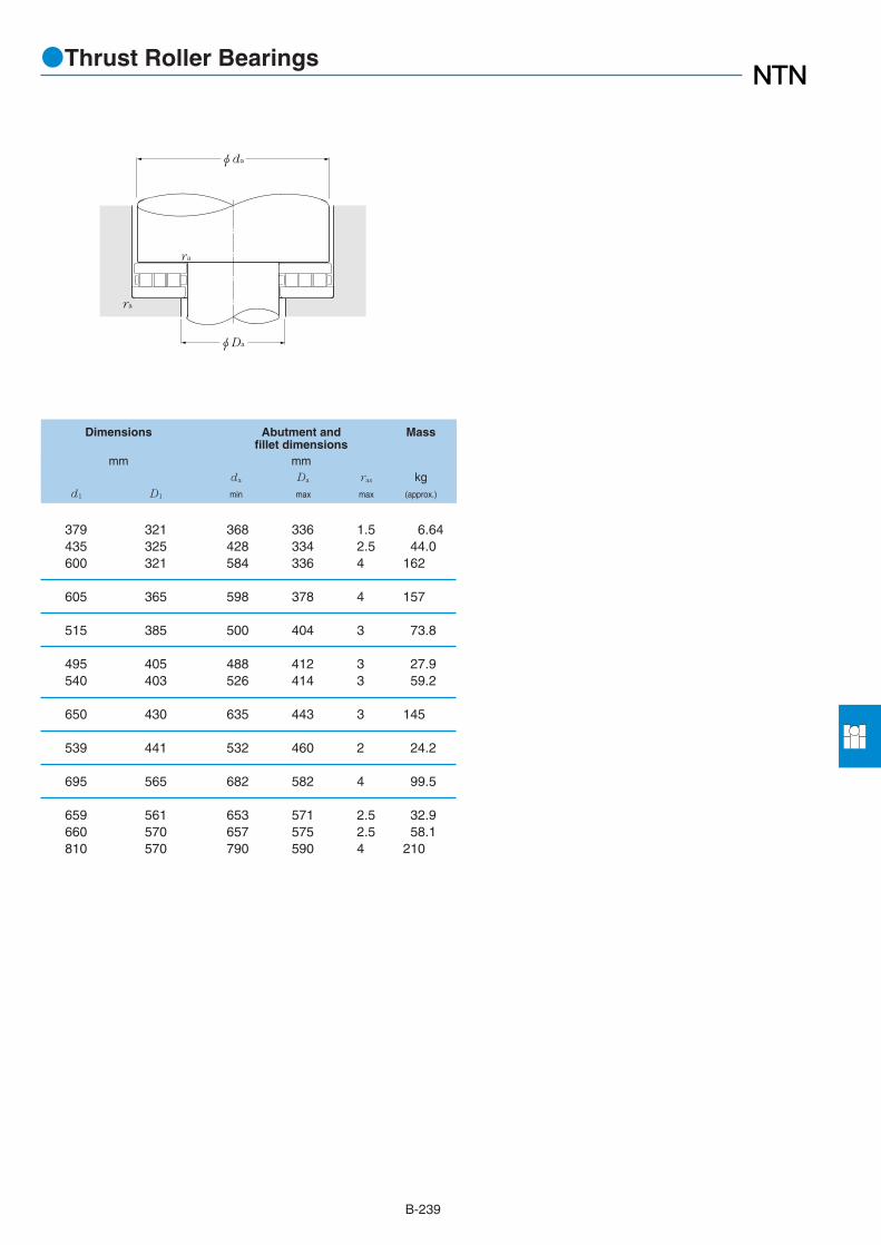
B-239
●Thrust Roller Bearings
Dimensions Abutment and Massfillet dimensions
mm mmda Da ras kg
d1 D1 min max max (approx.)
379 321 368 336 1.5 6.64435 325 428 334 2.5 44.0600 321 584 336 4 162
605 365 598 378 4 157
515 385 500 404 3 73.8
495 405 488 412 3 27.9540 403 526 414 3 59.2
650 430 635 443 3 145
539 441 532 460 2 24.2
695 565 682 582 4 99.5
659 561 653 571 2.5 32.9660 570 657 575 2.5 58.1810 570 790 590 4 210
φda
ra
φDa
ra

B-240
r
r1
Drawing A Drawing B
φD
φD1
φdr
r1
T
φd1
●Tapered Roller Thrust Bearings (Single Direction Type)
1 Minimal allowable dimension for chamfer dimension r or r1.Remarks: 1. Bearing numbers marked "*" designate inch system bearings.
d 101.600~254.000mm
Boundary dimensions Basic load ratings Bearingdynamic static dynamic static numbers
mm kN kgf
d D T rs min1
r1s min1
Ca Coa Ca Coa
107.950
114.300
127.000
130
145
152.400
170
174.625
168.275
177.800
203.200
220
227
228.600
215.900 46.038 3.3 3.3 700 2,730 71,000 279,000 *CRT2010215.900 46.038 1.5 1.5 805 2,920 82,000 297,000 *CRT2014
228.600 69.850 2 5.6 1,070 3,100 109,000 320,000 *CRT2223
250.825 53.975 4.06 4.06 995 3,750 102,000 380,000 *CRT2301
266.700 58.738 4 4 1,130 4,650 115,000 475,000 *CRT2503
225 55 2.1 2.1 640 2,590 65,500 264,000 CRT2615
190 31 1 1 216 815 22,000 83,000 CRT2906
317.500 69.850 6.4 6.4 1,520 6,250 155,000 640,000 *CRT3018
304.800 69.850 6.4 6.4 1,250 4,950 127,000 505,000 *CRT3407304.800 69.850 6.4 6.4 1,350 5,100 138,000 520,000 *CRT3409
320 100 6 6 1,620 6,400 166,000 650,000 CRT3410
358.775 82.550 6.4 6.4 1,720 7,050 175,000 720,000 *CRT3503
368.300 82.550 8 8 2,190 8,900 223,000 910,000 *CRT3617
419.100 92.075 9.7 9.7 2,400 10,200 244,000 1,040,000 *CRT4108419.100 92.075 9.7 9.7 2,490 10,600 254,000 1,090,000 *CRT4112419.100 120.650 9.7 9.7 2,240 9,450 229,000 965,000 *CRT4105
370 90 4 4 1,690 7,250 172,000 740,000 CRT4405
325 50 2 2 610 2,720 62,000 277,000 CRT4502
482.600 104.775 11.2 11.2 3,450 15,600 350,000 1,590,000 *CRT4604482.600 104.775 11.2 11.2 3,250 14,300 330,000 1,460,000 *CRT4605
546.100 127.000 16 16 5,700 27,900 580,000 2,850,000 *CRT4707V
539.750 117.475 11.2 11.2 3,850 17,100 395,000 1,740,000 *CRT5103
234.950
254.000
101.600

B-241
●Tapered Roller Thrust Bearings (Single Direction Type)
r
r1
Drawing C
Drawing Dimensions Massno.
mm kg
D1 d1 (approx.)
B 101.6 215.9 9.06A 102.591 215.138 8.23
B 107.95 228.6 14.0
B 114.3 250.825 13.9
B 128.6 265.1 17.7
A 130.3 225 9.14
B 147 188 2.30
B 152.4 317.5 28.5
B 168.275 304.8 24.6A 168.275 302.5 22.2
A 170.5 320 39.4
B 174.625 358.775 39.9
B 177.8 368.3 45.0
A 203.2 416.7 60.9B 203.2 419.1 64.9B 203.2 419.1 79.8
A 221 369 39.2
A 227 325 13.3
B 230.6 480.6 101A 230.6 480.6 93.2
C 234.95 546.1 160
A 254 539.75 140

B-242
r
r1
Drawing A Drawing B
φD
φD1
φdr
r1
T
φd1
●Tapered Roller Thrust Bearings (Single Direction Type)
1 Minimal allowable dimension for chamfer dimension r or r1.Remarks: 1. Bearing numbers marked "*" designate inch system bearings.
d 260~920mm
Boundary dimensions Basic load ratings Bearingdynamic static dynamic static numbers
mm kN kgf
d D T rs min1
r1s min1
Ca Coa Ca Coa
360 60 2.1 2.1 890 3,950 91,000 400,000 CRT5207
603.250 136.525 11.2 11.2 5,100 23,300 520,000 2,380,000 *CRT5613
395 80 3 3 1,330 5,150 136,000 525,000 CRT5804
580 155 7.5 7.5 4,800 18,900 490,000 1,920,000 CRT6408710 235 7.5 7.5 8,600 31,000 880,000 3,200,000 CRT6401
460 96 3 3 1,640 7,300 167,000 745,000 CRT6803
460 85 3 3 1,390 5,850 142,000 600,000 CRT7012
600 120 6.9 5.5 3,800 17,500 390,000 1,780,000 CRT7207
711.200 146.050 9.7 9.7 6,100 30,500 620,000 3,150,000 *CRT8101
711.2 166.5 5 5 8,250 33,500 840,000 3,400,000 CRT8104
570 100 4 4 1,560 7,750 159,000 790,000 CRT9002750 145 8 8 6,350 31,500 645,000 3,200,000 CRT9003
990.600 196.850 12.7 12.7 12,100 62,500 1,230,000 6,400,000 *CRT10202
745 105 5 5 2,530 13,600 258,000 1,390,000 CRT12002
1,120 150 7.5 7.5 5,500 32,500 560,000 3,350,000 CRT18401
260
279.400
290
340
350
360
406.400
406.4
450
508.000
600
920
320

B-243
●Tapered Roller Thrust Bearings (Single Direction Type)
r
r1
Drawing C
Drawing Dimensions Massno.
mm kg
D1 d1 (approx.)
A 260.3 360 18.3
B 279.4 603.25 205
A 291 395 27.8
B 320.5 580 179A 320 708 465
A 340 460 49.9
A 351 450 37.3
A 366 620 136
B 406.4 711.2 245
A 409 709 301
A 452 570 60.3B 450.5 750 257
B 508 990.6 701
A 600.5 745 101
A 922 1,118 295

B-244
T
A
φD1
r1
ra
r1a
r
φda φDaφD φd
●Tapered Roller Thrust Bearings (Double Direction Type)
1 Minimum allowable dimension for chamfer dimension r or r1.Remarks: 1. Ca does not means allowable load ratings. Please contact NTN Engineering.
d 170~550mm
Boundary dimensions Basic load ratings Bearing Abutment and Massdynamic static numbers fillet dimensions
mm kN kgf mm kg
d D T rs min1
r1s min1
Ca Ca D1 A da Da ra r1a (approx.)
240 84 2.5 1 365 37,000 CRTD3401 184 20 179 190 2 1 12
280 90 2 1 645 65,500 CRTD3618 196 20 189 202 2 1 20
560 138 3 4 1,630 166,000 CRTD4013 430 40 413 438 2.5 3 105
300 96 2 1 435 44,000 CRTD4203 236 22 228 242 2 1 19.5
340 130 2 1.5 860 88,000 CRTD4401 250 39 242 256 2 1.5 42.1
320 96 2 0.6 405 41,500 CRTD4802 256 22 246 262 2 1 21380 105 1.5 1.5 840 85,500 CRTD4803 270 27 267 274 1.5 1.5 41.5
360 96 1.5 0.6 635 64,500 CRTD5007 285 24 274 289 1.5 0.6 28380 100 2 1 905 92,000 CRTD5005 275 22 266 281 2 1 40
360 92 2 1 580 59,500 CRTD5216 285 20 272 291 2 1 26400 120 3 1.5 920 93,500 CRTD5217 290 25 276 298 2.5 1.5 51.5
420 100 2 2 880 89,500 CRTD6001 330 23 320 335 2 2 38
530 200 5 1.5 2,500 255,000 CRTD6104 345 56 332 357 4 1.5 165
440 108 3 2 980 100,000 CRTD6406 355 20 344 363 2.5 2 43470 130 3 2 1,390 142,000 CRTD6404 350 30 335 358 2.5 2 73
490 130 3 1.1 1,150 118,000 CRTD7012 390 30 375 398 2.5 1.5 72
560 130 3 2 1,630 166,000 CRTD7612 430 32 410 438 2.5 2 102
560 160 5 2 1,660 169,000 CRTD8201 440 40 428 446 4 2 111
620 170 3 1.1 2,190 223,000 CRTD8403 465 35 448 473 2.5 1 155
645 167 5 2 2,070 211,000 CRTD8802 500 50 470 495 2 2 176
720 200 4 4 3,450 355,000 CRTD9408 535 40 507 545 3 3 261
760 230 4 2 2,910 296,000 CRTD11002 610 50 577 622 4 2 296
170
180
200
212
220
250
260
300
240
305
350
380
320
410
420
440
470
550

B-245

B-246
●Self-Aligning Thrust Roller Bearings
d 100~200mm
Boundary dimensions Basic load ratings Bearing Dimensionsdynamic static dynamic static numbers
mm kN kgf mm
d D T rs min1
Ca Coa Ca Coa D1 d1 B1 C A
φD1
φD
C
A
T
φd1
φdB1 r
r
1 Minimum allowable dimension for chamfer dimension r or r1.
170 42 1.5 345 1,160 35,500 118,000 29320 129 163 14 20.8 58210 67 3 685 2,130 69,500 217,000 29420 146 200 24 32 62
190 48 2 445 1,500 45,000 152,000 29322 143 182 16 23 64230 73 3 845 2,620 86,500 267,000 29422 162 220 26 35 69
210 54 2.1 535 1,770 54,500 181,000 29324 159 200 18 26 70250 78 4 975 3,050 99,000 310,000 29424 174 236 29 37 74
225 58 2.1 615 2,100 62,500 215,000 29326 171 215 19 28 76270 85 4 1,080 3,550 110,000 360,000 29426 189 255 31 41 81
240 60 2.1 685 2,360 70,000 241,000 29328 183 230 20 29 82280 85 4 1,110 3,750 114,000 385,000 29428 199 268 31 41 86
215 39 1.5 340 1,340 34,500 136,000 29230 178 208 14 19 82250 60 2.1 675 2,390 68,500 243,000 29330 194 240 20 29 87300 90 4 1,280 4,350 131,000 445,000 29430 214 285 32 44 92
225 39 1.5 360 1,460 36,500 149,000 29232 188 219 14 19 86270 67 3 820 2,860 84,000 292,000 29332 208 260 24 32 92320 95 5 1,500 5,150 153,000 525,000 29432 229 306 34 45 99
240 42 1.5 425 1,770 43,500 180,000 29234 198 233 15 20 92280 67 3 855 3,050 87,000 310,000 29334 216 270 23 32 96340 103 5 1,660 5,750 169,000 590,000 29434 243 324 37 50 104
250 42 1.5 450 1,920 45,500 196,000 29236 208 243 15 20 97300 73 3 995 3,600 102,000 365,000 29336 232 290 25 35 103360 109 5 1,840 6,200 188,000 635,000 29436 255 342 39 52 110
270 48 2 530 2,230 54,000 227,000 29238 223 262 15 24 104320 78 4 1,150 4,250 117,000 430,000 29338 246 308 27 38 110380 115 5 2,010 6,800 205,000 695,000 29438 271 360 41 55 117
280 48 2 535 2,300 54,500 234,000 29240 236 271 15 24 108340 85 4 1,280 4,600 131,000 470,000 29340 261 325 29 41 116400 122 5 2,230 7,650 228,000 780,000 29440 286 380 43 59 122
100
110
120
130
140
150
160
170
180
190
200

B-247
●Self-Aligning Thrust Roller Bearings
130 150 1.5 3.94150 175 2.5 11.5
145 165 2 5.78165 190 2.5 15
160 180 2 7.92180 205 3 18.6
170 195 2 9.76195 225 3 23.7
185 205 2 11.4205 235 3 25.2
179 196 1.5 4.56195 215 2 12220 250 3 30.5
189 206 1.5 4.88210 235 2.5 15.9230 265 4 37
201 218 1.5 6.02220 245 2.5 16.6245 285 4 45
211 228 1.5 6.27235 260 2.5 21.2260 300 4 52.9
225 245 2 8.8250 275 3 26275 320 4 62
235 255 2 9.14265 295 3 31.9290 335 4 73.3
Abutment and Massfillet dimensions
mm kgda Da ras
min max max (approx.)
Fr
Fa≦0.55
Pa=Fa+1.2Fr
Poa=Fa+2.7Fr
when
Equivalent bearing loaddynamic
static
φDa
φda
ra
ra
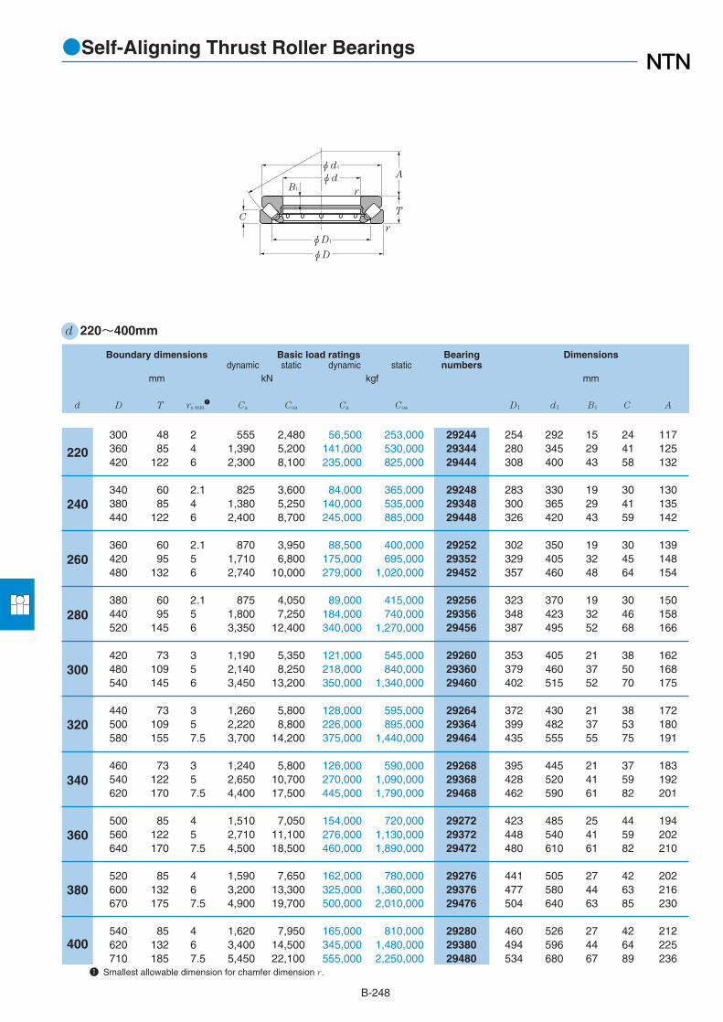
B-248
●Self-Aligning Thrust Roller Bearings
d 220~400mm
260
320
380
Boundary dimensions Basic load ratings Bearing Dimensionsdynamic static dynamic static numbers
mm kN kgf mm
d D T rs min1
Ca Coa Ca Coa D1 d1 B1 C A
φD1
φD
C
A
T
φd1
φdB1 r
r
1 Smallest allowable dimension for chamfer dimension r.
300 48 2 555 2,480 56,500 253,000 29244 254 292 15 24 117360 85 4 1,390 5,200 141,000 530,000 29344 280 345 29 41 125420 122 6 2,300 8,100 235,000 825,000 29444 308 400 43 58 132
340 60 2.1 825 3,600 84,000 365,000 29248 283 330 19 30 130380 85 4 1,380 5,250 140,000 535,000 29348 300 365 29 41 135440 122 6 2,400 8,700 245,000 885,000 29448 326 420 43 59 142
360 60 2.1 870 3,950 88,500 400,000 29252 302 350 19 30 139420 95 5 1,710 6,800 175,000 695,000 29352 329 405 32 45 148480 132 6 2,740 10,000 279,000 1,020,000 29452 357 460 48 64 154
380 60 2.1 875 4,050 89,000 415,000 29256 323 370 19 30 150440 95 5 1,800 7,250 184,000 740,000 29356 348 423 32 46 158520 145 6 3,350 12,400 340,000 1,270,000 29456 387 495 52 68 166
420 73 3 1,190 5,350 121,000 545,000 29260 353 405 21 38 162480 109 5 2,140 8,250 218,000 840,000 29360 379 460 37 50 168540 145 6 3,450 13,200 350,000 1,340,000 29460 402 515 52 70 175
440 73 3 1,260 5,800 128,000 595,000 29264 372 430 21 38 172500 109 5 2,220 8,800 226,000 895,000 29364 399 482 37 53 180580 155 7.5 3,700 14,200 375,000 1,440,000 29464 435 555 55 75 191
460 73 3 1,240 5,800 126,000 590,000 29268 395 445 21 37 183540 122 5 2,650 10,700 270,000 1,090,000 29368 428 520 41 59 192620 170 7.5 4,400 17,500 445,000 1,790,000 29468 462 590 61 82 201
500 85 4 1,510 7,050 154,000 720,000 29272 423 485 25 44 194560 122 5 2,710 11,100 276,000 1,130,000 29372 448 540 41 59 202640 170 7.5 4,500 18,500 460,000 1,890,000 29472 480 610 61 82 210
520 85 4 1,590 7,650 162,000 780,000 29276 441 505 27 42 202600 132 6 3,200 13,300 325,000 1,360,000 29376 477 580 44 63 216670 175 7.5 4,900 19,700 500,000 2,010,000 29476 504 640 63 85 230
540 85 4 1,620 7,950 165,000 810,000 29280 460 526 27 42 212620 132 6 3,400 14,500 345,000 1,480,000 29380 494 596 44 64 225710 185 7.5 5,450 22,100 555,000 2,250,000 29480 534 680 67 89 236
220
240
280
300
340
360
400

B-249
●Self-Aligning Thrust Roller Bearings
260 275 2 9.94285 315 3 34.5310 355 5 77.8
285 305 2 17.5300 330 3 36.6330 375 5 82.6
305 325 2 18.6330 365 4 52360 405 5 108
325 345 2 19.8350 390 4 54.6390 440 5 140
355 380 2.5 30.9380 420 4 75.8410 460 5 147
375 400 2.5 33.5400 440 4 79.9435 495 6 181
395 420 2.5 34.4430 470 4 107465 530 6 230
420 455 3 50.5450 495 4 112485 550 6 240
440 475 3 53.4480 525 5 143510 575 6 267
460 490 3 55.8500 550 5 148540 610 6 321
Abutment and Massfillet dimensions
mm kgda Da ras
min max max (approx.)
Fr
Fa≦0.55
Pa=Fa+1.2Fr
Poa=Fa+2.7Fr
when
Equivalent bearing loaddynamic
static
φDa
φda
ra
ra

B-250
●Self-Aligning Thrust Roller Bearings
d 420~800mm
Boundary dimensions Basic load ratings Bearing Dimensionsdynamic static dynamic static numbers
mm kN kgf mm
d D T rs min1
Ca Coa Ca Coa D1 d1 B1 C A
φD1
φD
C
A
T
φd1
φdB1 r
r
1 Smallest allowable dimension for chamfer dimension r.
580 95 5 2,100 10,400 214,000 1,060,000 29284 489 564 30 46 225650 140 6 3,600 15,500 365,000 1,580,000 29384 520 626 48 68 235730 185 7.5 5,500 22,800 560,000 2,330,000 29484 556 700 67 89 244
600 95 5 2,150 10,900 219,000 1,110,000 29288 508 585 30 49 235680 145 6 3,800 16,400 385,000 1,680,000 29388 548 655 49 70 245780 206 9.5 6,400 26,200 650,000 2,670,000 29488 588 745 74 100 260
620 95 5 2,150 11,000 219,000 1,120,000 29292 530 605 30 46 245710 150 6 4,200 18,500 430,000 1,880,000 29392 567 685 51 72 257800 206 9.5 6,600 27,900 670,000 2,840,000 29492 608 765 74 100 272
650 103 5 2,400 12,000 245,000 1,220,000 29296 556 635 33 55 259730 150 6 4,200 18,700 430,000 1,910,000 29396 590 705 51 72 270850 224 9.5 7,500 31,500 765,000 3,200,000 29496 638 810 81 108 280
670 103 5 2,540 13,000 259,000 1,330,000 292/500 574 654 33 55 268750 150 6 4,300 19,300 435,000 1,970,000 293/500 611 725 51 74 280870 224 9.5 7,850 33,000 805,000 3,350,000 294/500 661 830 81 107 290
710 109 5 2,720 14,000 278,000 1,430,000 292/530 610 692 39 55 288800 160 7.5 5,000 23,300 510,000 2,380,000 293/530 648 772 54 76 295920 236 9.5 8,650 36,000 880,000 3,700,000 294/530 697 880 86 115 308
750 115 5 3,200 16,600 325,000 1,700,000 292/560 642 732 38 61 302980 250 12 9,300 40,500 945,000 4,100,000 294/560 743 938 90 121 321
800 122 5 3,500 18,300 355,000 1,870,000 292/600 686 780 40 63 3211,030 258 12 10,200 44,500 1,040,000 4,550,000 294/600 785 978 90 125 360
850 132 6 4,300 22,800 435,000 2,330,000 292/630 717 822 44 70 3381,090 280 12 11,600 51,000 1,180,000 5,200,000 294/630 830 1,040 100 136 365
1,150 290 15 12,900 57,000 1,320,000 5,850,000 294/670 880 1,105 106 138 387
1,060 212 9.5 8,350 40,500 850,000 4,150,000 293/710 850 1,030 76 102 3931,220 308 15 14,100 63,500 1,440,000 6,450,000 294/710 925 1,165 112 150 415
1,280 315 15 15,700 69,000 1,600,000 7,000,000 294/750 983 1,220 116 152 436
1,360 335 15 17,000 79,000 1,730,000 8,050,000 294/800 1,040 1,300 120 162 462
420
440
460
480
500
530
560
600
630
670
710
750
800

B-251
●Self-Aligning Thrust Roller Bearings
490 525 4 76.6525 575 5 172560 630 6 333
510 545 4 79.6550 600 5 195595 670 8 428
530 570 4 82.8575 630 5 221615 690 8 443
555 595 4 98.6595 650 5 228645 730 8 552
575 615 4 102615 670 5 235670 750 8 569
610 650 4 122655 710 6 288715 790 8 669
640 690 4 144755 835 10 815
690 735 4 171800 885 10 897
725 780 5 213845 935 10 1,110
895 990 12 1,280
870 930 8 669950 1,050 12 1,520
995 1,105 12 1,690
1,060 1,175 12 2,040
Abutment and Massfillet dimensions
mm kgda Da ras
min max max (approx.)
Fr
Fa≦0.55
Pa=Fa+1.2Fr
Poa=Fa+2.7Fr
when
Equivalent bearing loaddynamic
static
φDa
φda
ra
ra

Bearings for special applications
Contents
Split cylindrical roller bearings: Double–fractured ⋯⋯⋯⋯⋯⋯⋯⋯⋯⋯C- 2
Split spherical roller bearings: Double–fractured⋯⋯⋯⋯⋯⋯⋯⋯⋯⋯⋯C- 3
Double–fractured split cylindrical roller bearings: Continuous casting equipment ⋯⋯C- 4
Cylindrical roller bearings with self-aligning rings: Continuous casting equipment ⋯⋯C- 5
Bearings for preparing rolls: Sendzimir rolling mills ⋯⋯⋯⋯⋯⋯⋯⋯⋯C- 6
Enclosed–type tapered roller bearings for wheels: Sintering machines ⋯⋯C- 8
Cylindrical roller bearings: Chain conveyors ⋯⋯⋯⋯⋯⋯⋯⋯⋯⋯⋯⋯C- 9
Tapered roller thrust bearings: Screw down operations⋯⋯⋯⋯⋯⋯⋯⋯C-10
Tension leveler roll unit: Cartridge unit ⋯⋯⋯⋯⋯⋯⋯⋯⋯⋯⋯⋯⋯⋯⋯C-14
Tension lever roll unit: Backup unit ⋯⋯⋯⋯⋯⋯⋯⋯⋯⋯⋯⋯⋯⋯⋯⋯C-15
Turn table bearings: 3–row cylindrical roller type ⋯⋯⋯⋯⋯⋯⋯⋯⋯⋯C-16
Sealed spherical roller bearings: Model WA ⋯⋯⋯⋯⋯⋯⋯⋯⋯⋯⋯⋯C-18
Spherical surface slide bearings ⋯⋯⋯⋯⋯⋯⋯⋯⋯⋯⋯⋯⋯⋯⋯⋯⋯C-20

Bearings for special applications

C-2
●Split Cylindrical Roller Bearings: Double–Fractured
Boundary dimensions Basic load ratings Bearing1 Drawingdynamic static dynamic static numbers no.
mm kN kgf
d D B C r1 r2 Cr Cor Cr Cor
d 120~770mm
Fixed sideDrawing A
C
B
r2
r1
φD φd
Free sideDrawing B
¡ Since the inner ring, outer ring andcage are split in two parts, it is possibleto mount the bearing in places where aunited bearing is difficult or impossibleto mount. (ie. Places where mountingfrom the shaft end is impossible, anobstacle exists on the shaft, or the shaftis very long.)
¡ Inspection and maintenance aftermounting is easy.
1 The marked "*" bearings has a spherical surface of outer rings outside dia. Remarks: 1. The above drawings are typical examples. Please contact NTN Engineering.
R254 125 60 C4 4 450 510 46,000 52,000 *RE2436 B*RE2437 A
254 114.3 63.5 C5 C2 555 720 56,500 73,500 RE2512 A
240 76 38 C3 C3 238 340 24,200 35,000 RE3220 ARE3221 B
240 76 38 C3 C3 238 340 24,200 35,000 RE3308 ARE3309 B
R340 120 56 C3.5 3.5 435 565 44,500 57,500 *RE3420 A*RE3421 B
285.75 109 55.5 C3.5 C3.5 415 580 42,500 59,000 RE3617 A
290 92 46 C3.5 C3.5 350 510 36,500 52,000 RE3812 ARE3813 B
311.15 109.5 60.3 C3.2 C3.2 480 760 49,000 77,500 RE4022 A
360 92 46 C3 C3 370 595 37,500 60,500 RE4206 ARE4207 B
360 92 46 C3 C3 350 550 35,500 56,500 RE4604 ARE4605 B
360 92 46 C3 C3 350 550 35,500 56,500 RE4702 ARE4703 B
360 92 46 C3 C3 350 550 35,500 56,500 RE5209 ARE5210 B
400 92 48 C3 C3 460 755 47,000 77,000 RE5606 BRE5607 A
622.3 272 160.4 C12 C6 2,900 4,250 295,000 435,000 RE6405 A
480 115 56 C3 C3 545 955 56,000 97,500 RE6702 ARE6703 B
R600 200 116 C6 6 1,940 3,250 198,000 330,000 *RE7203 B
740 294 170 C4 C4 3,650 6,150 370,000 625,000 RE9208 B
850.9 360 210 C12 C6 5,250 9,050 535,000 525,000 RE10013 B
800 180 90 C3 C3 1,370 2,570 140,000 262,000 RE11501 ARE11502 B
900 200 103 C3 C3 1,650 3,150 168,000 325,000 RE12801 ARE12802 B
900 200 103 C3 C3 1,650 3,150 168,000 325,000 RE13405 ARE13406 B
1,070 300 180 C2.5 C6 5,300 12,000 540,000 1,230,000 RE15404 ARE15405 B
120
127
160
164
170
190
210
230
235
260
280
335
575
640
670
770
320
360
460
500
180
200

C-3
●Split Spherical Roller Bearings: Double–Fractured
r2 r2 r2
r1r1 r1
φD φD φDφd φd φd
C C C
B B B
Drawing A Drawing CDrawing B
d 150~1,400mm
150
200
190
240
315.9
320
360
505
530
850
1 120
1 200
1 200
1 400
260 121 67 2.1 2.1 420 720 43,000 73,500 2PE3012 A
290 150 90 2.1 2.1 785 1,440 80,000 147,000 2PE3801 A
340 152 90 3 3 935 1,620 95,000 165,000 2PE4002 A
400 173 104 4 4 1,070 1,990 109,000 203,000 2PE4802 A
530 210 133 5 5 2,130 4,150 218,000 420,000 2PE6301 A
480 226 121 7.5 4 1,590 2,930 163,000 299,000 2PE6401 A
540 212 134 3 5 2,270 4,350 231,000 445,000 2PE7202 A
750 248 140 5 5 2,680 6,200 273,000 635,000 2PE10101 A
750 248 140 5 5 2,680 6,200 273,000 633,000 2PE10601 A
1,280 375 249 12 12 8,800 19,900 895,000 2,020,000 2PE17009 A
1,540 525 355 7.5 7.5 14,200 43,500 1,450,000 4,400,000 2PE22401 B
1,700 790 410 ― 9.5 17,200 44,000 1,750,000 4,500,000 2PE24004 C
1,700 695 410 ― 9.5 15,600 44,000 1,590,000 4,500,000 2PE24005 C
1,900 880 530 ― 12 22,900 65,500 2,340,000 6,650,000 2PE28001 C
Boundary dimensions Basic load ratings Bearing1 Drawingdynamic static dynamic static numbers no.
mm kN kgf
d D B C r1 r2 Cr Cor Cr Cor

C-4
d 100~230mm
φD
RB
φd φDR
L
H
¡ These bearings are designed to be a full complement roller type and have high rating load for heavy loads, ultra low speed rotationand space-saving.
¡ These bearings provide a multi-seal with a labyrinth ring, seal ring and special rubber seal to prevent water from invading.¡ The clamping ring of the inner ring is not needed anymore and the structure of direct clamping is applied to make a compact bearing.¡ Bearings have a self-aligning nature due to the roll deflection since the outer ring outside diameter and the housing inner diameter
are spherical.¡ Application of a water cooling jacket type housing controls rising bearing temperatures.
●Double–Fractured Split Cylindrical Roller Bearings:Continuous Casting Equipment
100
110
120
190
130
230
150
140
115
145
165
180
154 145 210 210 355 790 36,000 80,500 RE2038V SS2020169 132 220 225 475 950 48,500 96,500 RE2039V SS2021
154 150 230 230 425 1,040 43,500 106,000 RE2224V SS2228180 230 230 SS2230154155 230 225
390 930 40,000 94,500 RE2225VSS2234
173 220 240 240 505 940 51,500 95,500 RE2306V SS2304
151 190 240 250 395 970 40,000 99,000 RE2439V SS2420
154 190 270 270 430 1,110 43,500 113,000 RE2628 SS2637
179 245 270 270 600 1,240 61,500 126,000 RE2827V SS2835191 250 265 265 525 1,280 53,500 131,000 RE2824V SS2825
196 260 280 280 630 1,440 64,500 147,000 RE2906V SS2908208 270 295 295 765 1,780 78,000 182,000 RE2907V SS2907
169 180 265 300 695 1,700 70,500 173,000 RE3036V SS3043
228 280 320 320 930 2,210 95,000 225,000 RE3311V SS3303
169 217.5 335 335 815 2,010 83,000 205,000 RE3621V SS3616235 280 340 340 1,030 2,580 106,000 263,000 RE3620V SS3415
233 280 370 370 1,320 3,100 134,000 320,000 RE3815V SS3804
239 300 450 450 1,590 3,700 162,000 380,000 RE4606 SS4601
Boundary dimensions Basic load ratings Bearing Housingdynamic static dynamic static numbers No.
mm kN kgf
d B H L DR Cr Cor Cr Cor

C-5
●Cylindrical Roller Bearings With Self-Aligning Rings:Continuous Casting Equipment
Boundary dimensions Basic load ratings Bearingdynamic static dynamic static numbers
mm kN kgf
d D B rs min1
Cr Cor Cr Cor
d 55~200mm
B
φD
r
r
φd
¡ These bearings are designed to be a full complement roller type and have high rating load.¡ Bearings have a self-aligning nature since the outer ring outside surface and aligning ring inside surface are spherical.
1 Smallest allowable dimension for chamfer dimension r.
110
120
75
55
130
140
160
150
170
180
200
90 32 1.1 85 203 8,700 20,700 R11A11V100 25 1.5 94.5 146 9,650 14,900 R11A12V
130 31 1.5 146 236 14,900 24,100 R1564V
170 60 2 297 720 30,500 73,000 R2260V180 56 2 325 635 33,000 65,000 R2252V
200 80 2 450 980 46,000 100,000 R2481V
200 69 2 405 935 41,500 95,500 R2674V210 80 2 495 1,090 50,500 112,000 R2677V
210 69 2 420 990 42,500 101,000 R2858V225 85 2.1 545 1,230 56,000 125,000 R2859V
250 100 2.1 710 1,620 72,500 165,000 R3056V
270 109 2.1 855 1,830 87,500 186,000 R3261V
260 90 2.1 635 1,510 65,000 154,000 R3444V
280 100 2.1 785 1,870 80,500 191,000 R3646V
340 112 3 1 160 2,470 119,000 252,000 R4051V

C-6
●Bearings for Preparing Rolls: Sendzimir Rolling Mills
Boundary dimensions Basic load ratings Bearing Drawingdynamic static dynamic static numbers no.
mm kN kgf
d D B C rs min1
rls min1
Cr Cor Cr Cor
d 70~180mm
Drawing DDrawing A Drawing B Drawing C
a r
r1
f
B
C
φDφd
H
¡ Since bearings are directly used in preparing rolls, the thickness of the outer ring is designed to be thicker than regular bearings.¡ Since high accuracy under heavy loads is required, these bearings are designed to have a capacity for heavy loads and high accuracy.¡ Several bearings are assembled on one shaft for operation, and the mutual difference of assembled thickness (Dimension H) of
bearings on the same shaft is very minimal.¡ When the outer ring outside surface is worn, it is possible to recycle it by grinding it to a certain level.
1 Minimal allowable dimension for chamfer dimension r or r1.
160 90 90 1.5 0.6 455 855 46,500 87,000 3RCS1414VUP C160 90 90 1.5 0.6 355 605 36,000 61,500 3RCS1418UP B
220 96 94 3.0 1.1 470 695 48,000 71,000 2R1840LLUP-1 F220 120 120 2.0 0.3 775 1,510 79,000 154,000 3R1827VUP E220 120 120 2.0 1.5 650 1,150 66,000 118,000 3R1829UP D200 130 130 2.0 1.5 675 1,260 69,000 128,000 3R1826UP D
255 120 120 1.5 1.0 715 1,350 73,000 138,000 3RCS2035UP A
300 160 159.5 1.5 2.0 1,480 2,700 151,000 275,000 3RCS2659UPV1 A300 172.6 172.6 1.5 2.0 1,580 2,930 161,000 299,000 3RCS2629UP A
406.4 171.04 171.04 2.5 4.0 2,060 3,800 210,000 390,000 3RCS3615UP B406.4 224 224 1.45 4.0 2,350 4,500 240,000 460,000 3RCS3618UP B
70
90
100
130
180

C-7
Sloping outer ring Assembled thickness Necessary Massnumber
mm mm kg
a f H (P/C) (approx.)
●Bearings for Preparing Rolls: Sendzimir Rolling Mills
Drawing E Drawing F
6 0.035 44.981(±0.010) 32 10.76 0.035 44.981(±0.010) 32 10.7
21 0.5 64.980(±0.008) 64 21.76 0.035 64.978(±0.008) 32 27.6
20.6 0.12 64.973(0~-0.010) 40 27.56 0.1 64.960(±0.008) 40 29.8
10 0.1 62.474(0.010~0) 32 28.0
10 0.1 84.954(±0.008) 40 67.410 0.1 84.954(±0.008) 40 73.0
25 0.15 113.150(±0.010) 56 13225 0.15 113.150(±0.010) 40 170

φd φD
C
B1
r
r1
●Enclosed–Type Tapered Roller Bearings for Wheels:Sintering Machines
1 Minimal allowable dimension for chamfer dimension r or r1.Remarks: 1. The marked "*" bearings are not prepared with oil holes.
d 85~130mm
¡ The double lip contact seal, which has a tight seal, is installed with the bearing side face to prevent dust from entering the bearings.¡ Greasing the bearings is possible when a notch is positioned at the central part of inner ring.
Boundary dimensions Basic load ratings Bearingdynamic static dynamic static numbers
mm kN kgf
d D B1 C rsmin1
r1smin1
Cr Cor Cr Cor
180 115 115 2.5 0.6 440 715 45,000 73,000 CRI-1760LL
180 100 100 3.0 1.0 530 835 54,500 85,500 CRI-1959LL*
180 100 100 2.5 0.8 440 675 45,000 68,500 CRI-2070LL
200 100 100 3.0 1.0 605 965 61,500 98,500 CRI-2272LL
230 138 138 3.0 0.3 820 1,660 83,500 169,000 CRI-2666LL
85
95
110
130
100
C-8

C-9
B
C
T
φd2 φd1 φd φD
●Cylindrical Roller Bearings: Chain Conveyors
d 28.3~56mm
¡ Since the outer ring directly supports heavy loads, the thickness of outer ring is designed to be thicker than regular bearings.¡ For operation under heavy loads and extremely low speed rotation, these bearings are designed to be a full complement roller type
and have high loads capacity.¡ To prevent foreign matter from entering the bearing, a labyrinth structure is applied, which has a narrower clearance between outer
ring and rib ring.
Boundary dimensions Basic load ratings Bearingdynamic static dynamic static numbers
mm kN kgf
d d1 d2 D B C T C Co C Co
28.3
38.4
38.7
41.75
50
56
45
46
44.05 47 125 55 62 94 197 241 20,100 24,500 R06A31V
60 66 150 90 99 138 390 585 40,000 59,500 R08A31V
56 56 150 70 75 112 315 420 32,500 42,500 R08A24V
64.16 71 175 80 85 125 395 575 40,500 59,000 R08A02V
73 73 150 60 60 60 278 405 28,300 41,000 R09A20V
73 73 150 60 60 60 278 405 28,300 41,000 R09A21V
72 72 156 60 70 70 280 355 28,600 36,500 R1099V
74 74 160 51 55 49 261 310 26,600 31,500 R11A01V73 73 150 60 60 60 278 405 28,300 41,000 R11A13V

C-10
U
φD
φd1
φF
H
b
Th
Rs
r1
V
●Tapered Roller Thrust Bearings: Screw Down Operations
1 Smallest allowable dimension for chamfer dimension r1.
D 149.225~641.350mm
¡ These bearings are designed to be a full complement roller type and have high static rating load for large axial loadapplications.
¡ Inner ring surface is spherical (convex or concave) to allow its circle center to meet the tip of the pressing screw.¡ For hoisting, bearings are designed to have a hole or bushing at the center of the inner ring, and a bushing on the outer ring.
Boundary dimensions Basic load ratings Bearingstatic numbers
mm kN kgf
D d1 H F r1s min1
Coa Coa
149.225 146.900 47.625 127.000 1.6 2,280 233,000 CRT0402V
174.625 172.300 52.375 152.400 1.6 3,300 335,000 CRT0503V
203.200 200.800 65.075 177.800 1.6 4,550 465,000 CRT0607V
266.700 264.300 80.950 228.600 1.6 7,750 790,000 CRT0701V
320.675 318.300 95.250 279.400 1.6 11,800 1,200,000 CRT0814V
377.825 375.500 111.125 330.200 1.6 16,300 1,660,000 CRT0908V
409.575 407.200 122.225 355.600 3.2 19,300 1,960,000 CRT1006V
438.150 435.800 130.175 381.000 3.2 21,600 2,210,000 CRT1104V
495.300 492.900 146.050 431.800 3.2 27,300 2,780,000 CRT1209V
495.300 492.900 146.050 431.800 3.2 32,000 3,250,000 CRT1212V
523.875 521.500 152.400 457.200 3.2 32,000 3,300,000 CRT1409V
554.000 555.000 190.500 465.430 1.7 36,000 3,700,000 CRT1206V
555.625 553.300 165.100 482.600 3.2 36,000 3,650,000 CRT1516V
581.025 578.700 168.275 508.000 3.2 38,500 3,950,000 CRT1610V
609.600 607.200 177.800 533.400 3.2 44,000 4,500,000 CRT1806V
641.350 639.000 184.150 558.800 3.2 49,000 4,950,000 CRT1807V

C-11
●Tapered Roller Thrust Bearings: Screw Down Operations
Dimensions Mass
mm kg
RS b U V Th (approx.)
228.6 12.7 4.7 1.2 M12 4.4
228.6 12.7 4.7 1.2 M12 6.7
254 15.875 6.4 1.2 M12 11
304.8 19.05 7.9 2 M20 24.1
381 22.225 10.3 2.4 M20 41.3
457.2 25.4 10.3 2.4 M24 73.7
508 28.575 10.3 2.4 M24 87.2
508 31.75 13.5 3.2 M24 105
558.8 34.925 13.5 3.2 M24 150
1,270 34.925 13.5 3.2 M24 150
635 34.925 13.5 3.2 M24 175
1,270 50 9.5 6 M24 245
635 38.1 13.5 3.2 M24 214
711.2 38.1 13.5 3.2 M24 238
762 38.1 13.5 3.2 M24 277
762 38.1 13.5 3.2 M24 317

C-12
φD
U
V
φd1
φF
HsH
b
Th
Th1Rs
r1
●Tapered Roller Thrust Bearings: Screw Down Operations
1 Smallest allowable dimension for chamfer dimension r1.
D 149.225~641.350mm
¡ These bearings are designed to be a full complement roller type and have high static rating load for large axial load applications.¡ Inner ring surface is spherical (convex or concave) to allow its circle center to meet the tip of the pressing screw.¡ For hoisting, bearings are designed to have a hole or bushing at the center of the inner ring, and a bushing on the outer ring.
Boundary dimensions Basic load ratings Bearingstatic numbers
mm kN kgf
D d1 H F r1s min1
Coa Coa
149.225 146.900 80 127.000 1.6 2,280 233,000 CRT0401V
174.625 172.300 61.392 152.400 1.6 3,300 335,000 CRT0504V
203.200 200.800 75 177.800 1.6 4,650 475,000 CRT0606V
266.700 264.300 94.412 228.600 1.6 7,750 790,000 CRT0505V
320.675 318.300 110.973 279.400 1.6 11,800 1,200,000 CRT0811V
377.825 375.500 129.007 330.200 1.6 16,300 1,660,000 CRT0909V
409.575 407.200 140.767 355.600 3.2 19,300 1,960,000 CRT1007V
438.150 435.800 150.673 381.000 3.2 21,600 2,210,000 CRT1105V
482.600 480.212 145.542 419.100 3.2 27,200 2,770,000 CRT1307V
495.300 492.900 170.612 431.800 3.2 32,000 3,250,000 CRT1211V
523.875 521.500 174.35 457.200 3.2 32,500 3,350,000 CRT1412V
533.400 533.400 177.8 457.200 1.6 33,500 3,400,000 CRT1411V
555.625 553.300 190.856 482.600 3.2 36,000 3,650,000 CRT1517V
581.025 578.700 193.78 508.000 3.2 39,000 4,000,000 CRT1214V
581.225 578.700 193.777 508.000 3.2 38,500 3,950,000 CRT1601V
609.600 607.240 202.167 533.400 3.2 44,500 4,550,000 CRT1812V
641.350 639.000 212.674 558.800 3.2 49,000 4,950,000 CRT1808V

C-13
2 "-" means that is not prepared with a bush.
●Tapered Roller Thrust Bearings: Screw Down Operations
Dimensions Mass
mm kg
RS Hs b U V Th Th12
(approx.)
457.2 47.625 12.7 4.7 1.2 M12 - 6.6
457.2 52.375 12.7 4.7 1.2 M12 - 10.1
508 65.075 15.875 6.4 1.2 M12 M16 17
609.6 80.950 19.05 7.9 2 M20 - 36.2
762 95.250 22.225 10.3 2.4 M20 - 61.3
914.4 111.125 25.4 10.3 2.4 M24 - 98.8
1,016 122.225 28.575 10.3 2.4 M24 - 127
1,016 130.175 31.75 13.5 3.2 M24 - 155
1,905 130.175 38.1 13.5 3.2 M24 - 182
1,066.8 146.050 34.925 13.5 3.2 M24 - 215
1,270 152.400 34.925 13.49 3.18 M24 - 259
1,981.2 161.925 31.75 9.5 9.5 M24 - 271
1,270 165.100 38.1 13.5 3.2 M24 - 316
1,320.8 166.880 38.1 13.5 6 M24 M42 350
1,422.4 168.275 38.1 13.5 3.2 M24 - 350
1,524 177.800 38.1 13.5 3.2 M30 M42 388
1,524 184.150 38.1 13.5 3.2 M24 - 469

●Tension Leveler Roll Unit: Cartridge Unit
Bearing numbers Boundary dimensions Allowable axiale load
mm kN kgf
d D L1 L2 L3 D1 L4
d 8~15mm
L3 L4
L2
L1
φd φD φD1
Cartrige Unit
CU8A01W+WK30/150 8 30 1,716 1,552 1,500 26 92 1.85 189
CU8A05W+WK50/185 8 50 2,066 1,902 1,850 26 92 1.85 189
CU8A05W+IM38/185 8 38 2,066 1,902 1,850 26 92 1.85 189
CU10B01W+WK25/220 10 25 2,433.5 2,280 2,200 24 80 0.715 73
CU10B01W+WK20/180 10 20 2,033.5 1,880 1,800 24 80 0.715 73
CU12B04W+WK40/150 12 40 1,716 1,566 1,500 32 92 2.02 206
CU12B07W+WK30/220 12 30 2,433.5 2,288 2,200 28 85 1.49 151
CU12B07W+IM38/180 12 38 2,033.5 1,888 1,800 28 85 1.49 151
CU12B08W+WK40/210 12 40 2,332 2,170 2,100 38 100 2.02 206
CU15A04W+IM60/220 15 60 2,433.5 2,270 2,200 38 94 3.78 380
C-14
¡ This unit has a precision small diameter and a long scaled roll, with the surface roughness of the roll designed to be low.¡ Angular ball bearings are assembled in multiple rows in the cartridge to obtain high load capacity in both axial directions
and at high speed.¡ This unit has established both low torque operation and tight sealing by a labyrinth structure and low-contact seals.

C-15
●Tension Lever Roll Unit: Backup Unit
Bearing numbers Boundary dimensions Basic load ratings Massdynamic static dynamic static
mm kN kgf kg
d D L L1 Cr Cor Cr Cor (approx.)
d 13~70mm
Type NKZ Type BUB
φd φDφd φD
L1
L
L1
L
Backup Unit
¡ This unit has established both low torque operation and tight sealing by a labyrinth structure and low-contact seals.¡ When further low torque is requested, the roll unit (Model BUB), which uses only the deep groove ball bearings, is available.¡ Since the unit is used as a backup roll, the accuracy and its surface roughness are designed to be low.
NKZ 13×34×190-2 13 34 190 150 42 68 4,300 6,900 1
NKZ 16×38×192 16 38 192 170 35.5 55.5 3,600 5,650 1.4
NKZ 20×50×153-1 20 50 153 115 77.5 116 7,900 11,900 1.9
BUB 24×63.5×150-01 24 63.5 190 140 26.6 23.4 2,710 2,390 2.4
NKZ 24×65×205-6 24 65 205 155 82.5 122 8,450 12,500 3.9
NKZ 24×65×294 24 65 294 244 98 153 10,000 15,600 5.8
NKZ 24×65×314-4 24 65 314 275 84 150 8,600 15,300 6.5
BUB 24×65×320-03 24 65 320 274 19.2 14.8 1,950 1,510 6.5
NKZ 26×75×208-5 26 75 208 160 112 163 11,400 16,700 5.1
NKZ 28×75×150 28 75 150 108 112 163 11,400 16,700 3.6
NKZ 30×65×196 30 65 196 146 114 186 11,600 18,900 3.8
NKZ 30×75×150-24 30 75 150 110 125 187 12,700 19,000 3.7
NKZ 30×75×230-19 30 75 230 180 151 228 15,400 23,200 5.8
NKZ 30×75×326-12 30 75 326 276 151 228 15,400 23,200 8.5
NKZ 40×90×195 40 90 195 145 128 214 13,000 21,900 7
NKZ 70×150×345-4 70 150 345 250 515 905 52,500 92,500 34.5

C-16
●Turn Table Bearings: 3–Row Cylindrical Roller Type
Boundary dimensions Gear spec Setting holes (inner ring) Setting holes (outer ring)
module number of gear teethzi za
Di Da H mz m z b Li (n) di Si mi ti La (n) da so to mo
1 Disparity positioned
Di 1,104~4,000mm
Zi - di
mi mo
Si
ti
K
C
b
Da
La
Ui
mz
Di
Ua
Li
O
R
Za - da
Hho
So
to
Drawing A
¡ These are compound type bearings which unite the double row thrust roller bearing and the radial roller bearing.¡ These bearings are designed so that rollers in each row support axial and moment loads respectively, and high rigidity and
long life can be obtained since the rolling parts make line contact.¡ They are suitable for tunnel excavating machines or cranes with frequent turns.
1,510 175 1,128 12 94 140 1,230 36 φ26 30 M24X3 45 1,460 36 φ26 108 52 M24X3
1,850 220 1,428 14 102 120 1,520 48 φ26 30 M24X3 50 1,795 48 φ26 - - -
2,180 260 1,656 18 92 180 1,800 40 φ33 30 M30X3.5 60 2,115 401φ33 - - -
2,660 230 2,196 12 183 170 2,300 48 φ33 35 M30X3.5 60 2,595 48 φ33 - - -
3,305 240 2,808 12 234 140 2,910 42 φ33 30 M30X3.5 55 3,240 42 φ33 - - -
4,700 348 4,032 16 252 210 4,175 88 φ42 50 M39X4 70 4,615 88 φ42 226 80 M39X4
1,104
1,400
1,620
2,172
2,784
4,000

C-17
●Turn Table Bearings: 3–Row Cylindrical Roller Type
Zi - di
mi
R
Za - da
K
C Si
ti
b
DaLa
Ui
mz
Di
Ua
Li
O
Hho
Drawing B
K2N-RTD22602PX1 A 1,306 1,284 1,166 15 15 20 11,500 6,700 1,410 1,170 680 143 930
K2N-RTD28601PX1 B 1,618 1,576 1,475 20 15 85 20,500 10,800 2,200 2,100 1,110 225 1,550
K2N-RTD33102PX1 B 1,902 1,844 1,710 20 25 55 28,900 14,600 3,050 2,950 1,490 310 2,650
K2N-RTD43902PX1 B 2,391 2,364 2,235 30 20 40 27,500 18,600 2,280 2,800 1,900 233 2,600
K2N-RTD56205PX1 B 3,034 3,000 2,846 20 15 85 36,500 22,000 4,500 3,700 2,240 460 3,850
K2N-RTD80602PX1 A 4,321 4,219 4,085 20 52 86 114,000 50,500 17,000 11,600 5,150 1,740 10,300
Unit mm
Bearing Drawing Dimensions Basic load ratings Mass
numbers no. static static
kN Tonf kg
O Ui Ua R K C (approx.)main
thrust linesub
thrust line radial line radial linemain
thrust linesub
thrust line

C-18
●Sealed Spherical Roller Bearings: Model WA
Boundary dimensions Basic load ratings Bearing numbersdynamic static dynamic static
mm kN kgf
d D B rs min1
Cr Cor Cr Cor Cylindrical bore Tapered bore2
1 Smallest allowable dimension for chamfer dimension r. 2 "K" indicates bearings have tapered bore with a taper ratio of 1: 12.
d 60~160mm
Tapered boretaper 1:12
Cylindrical bore
φD
B
φd φd
r
r
¡ Special contact type rubber seal prevents foreign matter from entering the bearings.¡ Compact design enables bearings to be mounted with the standard type of plummer blocks (SN5, SN2).¡ Greasing bearings is possible since lubrication grooves and holes are provided on the outer ring.¡ Bearings are prelubricated with grease and can be directly mounted on machines.
60
65
70
75
80
85
90
95
100
110
120
130
140
150
160
110 36 1.5 115 147 11,700 15,000 LH-WA22212BLLS LH-WA22212BLLSK
120 39 1.5 143 179 14,600 18,300 LH-WA22213BLLS LH-WA22213BLLSK
125 39 1.5 154 201 15,700 20,500 LH-WA22214BLLS LH-WA22214BLLSK
130 39 1.5 166 223 16,900 22,800 LH-WA22215BLLS LH-WA22215BLLSK
140 41 2 179 239 18,300 24,400 LH-WA22216BLLS LH-WA22216BLLSK
150 44 2 206 272 21,000 27,800 LH-WA22217BLLS LH-WA22217BLLSK
160 50.4 2 256 345 26,200 35,000 LH-WA22218BLLS LH-WA22218BLLSK
170 51 2.1 294 390 30,000 39,500 WA22219BLLS WA22219BLLSK
180 60.3 2.1 315 415 32,000 42,500 WA22220BLLS WA22220BLLSK
200 69.8 2.1 410 570 42,000 58,000 WA22222BLLS WA22222BLLSK
215 76 2.1 485 700 49,500 71,500 WA22224BLLS WA22224BLLSK
230 80 3 570 790 58,000 80,500 WA22226BLLS WA22226BLLSK
250 88 3 685 975 70,000 99,500 WA22228BLLS WA22228BLLSK
270 96 3 775 1,160 79,000 119,000 WA22230BLLS WA22230BLLSK
290 104 3 870 1,290 88,500 132,000 WA22232BLLS WA22232BLLSK

C-19
●Sealed Spherical Roller Bearings: Model WA
1 Y1 0.67 Y2
Fa
Fr
X Y X Y
≦eFa
Fr>e
Pr=XFr+YFa
Por=Fr+YoFa
For values of e, Y2 and Yo
see the table below.
Equivalent bearing loaddynamic
static
φDa φda
ra
ra
Abutment and fillet dimensions Constant Axial load factors Mass (approx.)
mm kgda Da ras Cylindrical Tapered
min max max max e Y1 Y2 Y0 bore bore
68.5 74.5 101.5 1.5 0.27 2.49 3.71 2.44 1.41 1.37
73.5 80 111.5 1.5 0.28 2.42 3.60 2.37 1.80 1.76
78.5 84 116.5 1.5 0.26 2.55 3.80 2.50 1.91 1.86
83.5 89.5 121.5 1.5 0.24 2.81 4.19 2.75 2.06 2.00
90 94.5 130 2 0.26 2.64 3.93 2.58 2.51 2.45
95 101 140 2 0.26 2.60 3.88 2.55 3.08 3.01
100 107 150 2 0.26 2.55 3.80 2.49 4.08 3.97
107 114 158 2 0.26 2.63 3.92 2.57 4.71 4.59
112 119 168 2 0.26 2.55 3.80 2.49 6.01 5.83
122 133 188 2 0.27 2.51 3.74 2.46 8.87 8.60
132 147 203 2 0.27 2.47 3.68 2.42 11.2 10.9
144 154 216 2.5 0.28 2.39 3.56 2.33 12.5 12.1
154 168 236 2.5 0.28 2.39 3.55 2.33 16.9 16.3
164 185 256 2.5 0.27 2.46 3.66 2.40 22.6 21.9
174 197 276 2.5 0.28 2.42 3.60 2.37 28.0 27.2

C-20
●Spherical Surface Slide Bearings
Boundary dimensions Basic load ratings Bearingdynamic static dynamic static numbers
mm α kN kgf
d D B C K (deg.) Cd Cs Cd Cs
d 110~420mm
Drawing ADivided by 1 place (outer ring)
Allowableadjustmentangleα
Drawing BDivided by 2 place (outer ring)
K
φd φD
B
C
Grease up type
180 85 70 160 6 1,100,000 6,600,000 112,000 670,000 W2222180 100 75 160 10 1,180,000 7,050,000 120,000 720,000 W2225
260 105 60 225 12 1,110,000 6,670,000 113,000 680,000 W3617
290 130 120 250 2 2,550,000 15,300,000 260,000 1,560,000 W4029
430 215 195 375 3 6,350,000 38,000,000 645,000 3,900,000 W52A07
350 69 69 320 - 2,170,000 13,000,000 221,000 1,320,000 W5605430 220 140 375 10 4,900,000 29,600,000 500,000 3,010,000 W5613
440 190 150 380 6 5,000,000 30,500,000 510,000 3,050,000 W6022
440 160 120 380 6 4,200,000 25,300,000 430,000 2,580,000 W6415
480 100 100 430 - 4,200,000 25,300,000 430,000 2,580,000 W7601
540 120 120 480 - 5,650,000 34,000,000 575,000 3,450,000 W8407
110
180
200
260
280
300
320
380
420
¡ These are self-aligning sliding bearings: the sliding parts form a spherical surface. The bearings also can support radial loads andaxial loads in either direction.
¡ A lubricant (oil or grease) should be used since the sliding parts are steel on steel.¡ These bearings are suitable for swinging and aligning movements, and used in joint-movement parts for industrial and construction machines.

C-21
●Spherical Surface Slide Bearings
Drawing CDivided by 1 place (outer ring)
Plastic sealed
Drawing DDivided by 2 place (outer ring)
Retaining ring (shrinkage fit) type(D ≧ 500mm)
Drawing Mass Remarksno.
kg
(approx.)
A 9.42C 10.3
A 16.1 Inner ring outside dia. with oil groove
B 33.0 Inner ring outside dia. with oil groove
B 140 Inner ring outside dia. with oil groove
B 18.7 Without oil hole, oil grooveB 106 Inner ring outside dia. with oil groove
B 101 Inner ring outside dia. with oil groove
B 72 Inner ring outside dia. with oil groove
B 52.9 Without oil hole, oil groove
D 85.0 Without oil hole, oil groove

Catalog List & Appendix Table

D-2
●Catalog List
●BALL AND ROLLER BEARINGS
Ball and Roller Bearings 2202/C/E/I/P/S
Large Bearings 2250/E/P
Miniature and Extra Small Ball Bearings 3013/E
Miniature Molded Rubber Bearings 3014/E
Ball Bearings Shield and Seal Types 3015/E
Care and Maintenance of Bearings 3017/E/S/P
HL Bearings 3020/E
Bearings with Solid Grease 3022/E/S/P
Large Size, Long Operating Life Bearing-EA type 3024/E/P
Tapered Roller Bearings ECO-Top 3026/E/S/C
Self-Aligning Spherical Roller Bearings LH Series 3027/E/S/C
Bearings for Clean Environment 3028/E
Insulated Bearings-Resin Coated Type 3204/E
Type E Spherical Roller Bearings 3701/E
Sealed Self-Aligning Roller Bearings-WA Type 3702/E/S
Spherical Roller Bearings-UA Type 3710/E
HUB BEARINGS 4601/E
Aerospace Bearings 8102/E
Precision Rolling Bearings for Machine Tools 8401/E
Super High-speed Precision Bearings for Main Spindles of Machine Tools 8403/E
●NEEDLE ROLLER BEARINGS
Needle Roller Bearings 2300/E/I/P/S
Miniature Cam Followers 3601/E
●CONSTANT VELOCITY JOINTS
Constant Velocity Joints for Automobiles 5601/JE
TRI-Ball Joint / Constant Velocity Joints 5602/E
Constant Velocity Joints for Industrial Machines 5603/E
●BEARING UNITS
Bearing Units 2400/E/I/S
Bearing Units with Ductile Cast Iron Housing 3901/E
Bearing Units Steel Series 3902/E
Bearing Units Stainless Series 3903/E
Bearing Units Plastic Housing Series 3904/E
Triple-Sealed Bearings for Bearing Units 3905/E
CATALOG TITLES CATALOG No.

D-3
●Catalog List
●PLUMMER BLOCKS
Plummer Blocks 2500E/S
●PRECISION BALL SCREWS
Precision Ball Screws 6000/E
Rolled Ball Screws 6206/E
●PARTS FEEDER
Parts Feeder 7018/E
NTN Parts Feeder with Standard Attachments (for Bolts or Washer) 7016/E
●CLUTCHES
One-way Clutches (Overrunning Clutches) 6402/E
●PLAIN BEARINGS
"BEAREE" NTN Engineering Plastics 5100/E
Miniature Plastic Sliding Screws 5112/E
NTN "BEARPHITE" Oil Impregnated Sintered Bearings 5202/E
Spherical Plain Bearings 5301/E
●HANDBOOK
Bearing Units Handbook 9011/E/S
Rolling Bearings Handbook 9012/E
Needle Roller Bearings Handbook 9013/E
●GUIDE BOOK
Parts Feeder Guide Book 7019/E
Automotive Products Guide Book 8021/E/D/F/C
New Products Guide 9208/E/C
Food Machinery Component Guide 9209/E
Product Catalog for Paper Manufacturing Machinery 9210/E
Steel Manufacturing Machinery Product Guide Book 9211/E
●ELECTRONIC CATALOG
NTN Electronic Catalog (CD-ROM for Windows) 7903/E
NTN Autoparts Catalog (CD-ROM for Windows) 7905/E
Reference Kit Program -Bearing Interchange- (CD-ROM for Windows) 7907/E
●OTHERS
Bearing Handling 9103/E/P/S
CATALOG TITLES CATALOG No.
Note : The above are basic numbers. Renewal of the suffix by a revision.
C:Chinese E:English F:French D:Germany I:ItalianK:Korean S:Spanish T:Thai TC: Taipei Chinese

D-4
●Appendix Table
―1―2―
34567
89
000102
0304/2205/28
06/32070809
1011121314
1516171819
2021222426
2830323436
3840444852
5660646872
7680848892
96/500/530/560/600
/630/670/710/750/800
/850/900/950/1000/1060
/1120/1180/1250/1320/1400
/1500/1600/1700/1800/1900
/2000
0.61
1.52
2.5
34567
89
101215
1720222528
3032354045
5055606570
7580859095
100105110120130
140150160170180
190200220240260
280300320340360
380400420440460
480500530560600
630670710750800
85090095010001060
11201180125013201400
15001600170018001900
2000
2 2.5
3 4 5
6 7 81011
1214151821
2327 ―32 ―
37 ―44 ― ―
― ― ― ― ―
― ― ― ― ―
― ― ― ― ―
― ― ― ― ―
― ― ― ― ―
― ― ― ― ―
― ― ― ― ―
― ― ― ― ―
― ― ― ― ―
― ― ― ― ―
― ― ― ― ―
― ― ― ― ―
―
0.8111.21.5
2222.52.5
2.53344
44 ―4 ―
4 ―5 ― ―
― ― ― ― ―
― ― ― ― ―
― ― ― ― ―
― ― ― ― ―
― ― ― ― ―
― ― ― ― ―
― ― ― ― ―
― ― ― ― ―
― ― ― ― ―
― ― ― ― ―
― ― ― ― ―
― ― ― ― ―
―
― ― ― ― ―
2.52.52.533
― ― ― ― ―
― ― ― ― ―
― ― ― ― ―
― ― ― ― ―
― ― ― ― ―
― ― ― ― ―
― ― ― ― ―
― ― ― ― ―
― ― ― ― ―
― ― ― ― ―
― ― ― ― ―
― ― ― ― ―
― ― ― ― ―
― ― ― ― ―
― ― ― ― ―
―
― ―1.822.3
3333.53.5
3.54.54.555
55 ―5 ―
5 ― ― ― ―
― ― ― ― ―
― ― ― ― ―
― ― ― ― ―
― ― ― ― ―
― ― ― ― ―
― ― ― ― ―
― ― ― ― ―
― ― ― ― ―
― ― ― ― ―
― ― ― ― ―
― ― ― ― ―
― ― ― ― ―
―
0.050.050.050.050.08
0.080.080.080.10.1
0.10.10.10.20.2
0.20.2 ―0.2 ―
0.2 ―0.3 ― ―
― ― ― ― ―
― ― ― ― ―
― ― ― ― ―
― ― ― ― ―
― ― ― ― ―
― ― ― ― ―
― ― ― ― ―
― ― ― ― ―
― ― ― ― ―
― ― ― ― ―
― ― ― ― ―
― ― ― ― ―
―
2.53456
79
111314
1617192124
2632343740
4244475258
6572788590
95100110115120
125130140150165
175190200215225
240250270300320
350380400420440
480500520540580
600620650680730
780820870920980
10301090115012201280
13601420150016001700
18201950206021802300
2430
―――――
―――――
―――――
― 4 4 4 4
4 4 4 4 4
5 7 7 7 8
8 8 9 9 9
9 9101011
1113131414
1616161919
2225252525
3131313137
3737373742
4848505457
5760637171
7878808895
―――――
―
1 1
1.2 1.5 1.8
2 2.5 3
3.5 3.5
4 4 5 5 5
5 7 7 7 7
7 7 7 7 7
7 9101010
1010131313
1313161618
1820202222
2424242828
3338383838
4646464656
5656565660
6969747882
82856390
100
106106112122132
140155160165175
190
―――――
―3.5455
55666
68―8―
8―888
1011121313
1313161616
1616191922
2224242727
3030303636
4248484848
6060606072
7272727278
888895
100106
106112118128128
140140145165175
185200206218230
250
1.41.52
2.32.6
34566
66777
710101010
1010101010
1213141515
1515191919
1919232326
2630303434
3737374545
5260606060
7575757590
9090909098
112112118128136
136140150165165
180180185206224
243265272290300
325
―――――
―――――
88999
912―12―
12―121213
1517182020
2020252525
2525303035
3540404545
5050506060
6980808080
100100100100118
118118118118128
150150160170180
180190200218218
243243250280300
315345355375400
425
―――――
―――――
―――――
― 16 16 16 16
16 16 16 16 18
20 23 24 27 27
27 27 34 34 34
34 34 40 40 46
46 54 54 60 60
67 67 67 80 80
95109109109109
136136136136160
160160160160175
200200218230243
243258272300300
325325335375400
―――――
―
―――――
―――――
―――――
― 22 22 22 22
22 22 22 22 23
27 30 32 36 36
36 36 45 45 45
45 45 54 54 63
63 71 71 80 80
90 90 90100100
125145145145145
180180180180218
218218218218236
272272290308325
325345355400400
438438450500545
―――――
―
―――――
―――――
―――――
― 0.3 0.3 0.3 0.3
0.3 0.3 0.3 0.3 0.3
0.3 0.3 0.3 0.3 0.3
0.3 0.3 0.3 0.3 0.3
0.3 0.3 0.6 0.6 0.6
0.6 0.6 0.6 0.6 0.6
1 1 1 1 1
1.1 1.5 1.5 1.5 1.5
2 2 2 2
2.1
2.1 2.1 2.1 2.13
3 3 4 4 4
4 5 5 5 5
5 5 6 6 6
―――――
―
0.050.050.050.080.08
0.1 0.1 0.150.150.15
0.2 0.2 0.3 0.3 0.3
0.3 0.3 0.3 0.3 0.3
0.3 0.3 0.3 0.3 0.3
0.3 0.3 0.3 0.6 0.6
0.6 0.6 1 1 1
1 1 1 1 1.1
1.1 1.1 1.1 1.1 1.1
1.5 1.5 1.5 2 2
2 2.1 2.1 2.1 2.1
2.1 2.1 2.1 2.1 3
3 3 3 3 3
4 4 4 5 5
5 5 5 6 6
6 6 6 6 7.5
7.5 7.5 7.5 9.5 9.5
9.5
― 4567
811131517
1920222428
3037394245
4752556268
72808590
100
105110120125130
140145150165180
190210220230250
260280300320360
380420440460480
520540560600620
650670710750800
85090095010001060
11201180125013201400
14601540163017201820
19502060218023002430
―
― ― ― ― ―
― ― ― ― ―
― ― ― ― ―
― 7777
77788
8999
10
1010111111
1313131416
1619191922
2225252531
3137373737
4444445050
5454576063
7173788082
858895
103109
109115122128―
― ― ― ― ―
―
―1.6 22.32.5
3 4 4 5 5
6 6 6 6 7
7 9 9 9 9
9 10 10 12 12
12 13 13 13 16
16 16 18 18 18
20 20 20 22 24
24 28 28 28 33
33 38 38 38 46
46 56 56 56 56
65 65 65 74 74
78 78 82 85 90
100 103 106 112 115
118 122 132 140 150
150 160 170 175 185
195 200 212 218 230
―
―――――
―――――
―― 8 88.5
8.5 11 11 11 11
11 13 13 14 14
14 16 16 16 19
19 19 22 22 22
24 24 24 27 30
30 36 36 36 42
42 48 48 48 60
60 72 72 72 72
82 82 82 95 95
100 100 106 112 118
128 136 140 145 150
155 165 175 185 195
195 206 218 230 243
258 265 280 290 308
―
―2.32.6 33.5
4 5 6 7 7
9 9 10 10 10
10 13 13 13 13
13 15 15 16 16
16 19 19 19 23
23 23 26 26 26
30 30 30 34 37
37 45 45 45 52
52 60 60 60 75
75 90 90 90
90
106 106 106 118 118
128 128 136 140 150
165 170 180 185 195
200 206 224 236 250
250 272 280 300 315
335 345 355 375 400
―
―――――
―― 10 10 10
11 11 13 13 13
13 17 17 17 17
17 20 20 22 22
22 25 25 25 30
30 30 35 35 35
40 40 40 45 50
50 60 60 60 69
69 80 80 80
100
100 118 118 118 118
140 140 140 160 160
170 170 180 190 200
218 230 243 250 258
272 280 300 315 335
335 355 375 400 425
450 462 475 500 530
―
―――――
―――――
―― 16 16 18
18 23 23 23 23
23 27 27 30 30
30 34 34 34 40
40 40 46 46 46
54 54 54 60 67
67 80 80 80 95
95109 109 109 136
136 160 160 160 160
190 190 190 218 218
230 230 243 258 272
300 308 325 335 355
365 375 400 438 462
462 488 515 545 ―
―――――
―
―――――
―――――
―― 22 22 23
23 30 30 30 30
30 36 36 40 40
40 45 45 45 54
54 54 63 63 63
71 71 71 80 90
90109 109 109 125
125 145 145 145 180
180 218 218 218 218
250 250 250 290 290
308 308 325 345 355
400 412 438 450 462
488 500 545 580 615
615 650 690 710 ―
―――――
―
―――――
―――――
―――――
―0.30.30.30.3
0.30.30.30.30.3
0.30.30.30.60.6
0.60.60.60.60.6
0.60.60.60.61
1 1 1 1 1.1
1.11.51.51.52
2 2.12.12.12.1
3 3 3 4 4
4 4 4 5 5
5 5 5 6 6
6 6 6 6 7.5
7.57.57.57.5―
―――――
―
―0.10.150.150.15
0.150.150.20.20.3
0.30.30.30.30.3
0.30.30.30.30.3
0.30.60.60.60.6
0.61111
111.11.11.1
1.11.11.11.11.5
1.52222
22.12.12.12.1
2.13333
44444
55555
66666
667.57.57.5
7.57.57.57.59.5
9.59.59.51212
―
― ― ― ― ―
― ―0.150.150.15
0.20.30.30.30.3
0.30.30.30.30.3
0.30.60.60.60.6
0.61111
111.11.11.1
1.11.11.11.11.5
1.52222
22.12.12.12.1
2.13333
44444
55555
66666
667.57.57.5
7.57.57.57.59.5
9.59.59.51212
―
― ―
678
712141719
2224262832
3542444752
5558626875
809095
100110
115125130140145
150160170180200
210225240260280
290310340360400
420460480520540
560600620650680
700720780820870
920980103010901150
12201280130014201500
15801660175018501950
2120224023602500―
―
― ― ― ― ―
― ― ― ― ―
― ― ―
78
88888
9999
10
1011111113
1314141616
1618191922
2224252831
3134373744
4450505757
5763636771
7171808285
92100103109112
118122132136140
145155― ― ―
― ― ― ― ―
―
― ― 2.52.82.8
34566
77889
1012121212
1313141516
1618181820
2022222424
2426282833
3335384246
4651565665
6574748282
82909094
100
100100112115118
128136140150155
165170180185195
200212218
230243
272280290308―
―
― ― ― ― ―
― ― ― ―
8
910101011
1214141415
1616171819
1922222224
2427273030
3033363642
4245485460
6066727282
829595
106106
106118118122128
128128145150155
170180185195200
212218236243250
265272290
300315
355365375400―
―
― ―
33.5
4
5679
10
1112121213
1416161618
1920202123
2326262630
3034343737
3741454652
5356606774
75829092
104
106118121133134
135148150157163
165167185195200
212230236250258
272280300308325
345355375
400412
462475500530―
―
― ― ― ― ―
― ― ― ― ―
1415161617
1822222224
2526272830
3035353540
4045455050
5056606069
69758090
100
100109118118140
140160160180180
180200200212218
218218250258272
290308315335345
365375412412438
462475500
530545
615630650690―
―
― ― ― ― ―
― ― ― ― ―
1920212123
2430303032
3435363840
4046464654
5460606767
6775808095
65100109122136
136150160160190
190218218243243
243272272280300
300300335355365
388425438462475
500515560560600
615650― ― ―
― ― ― ― ―
―
― ― ― ― ―
― ― ― ― ―
2527292930
3240404043
4547485054
5463636371
7180809090
100109109109125
125136145160180
180200218218250
250290290325325
325355355375400
400400450462488
515560580615630
670690730750800
825875― ― ―
― ― ― ― ―
―
―――――
―――――
―――
0.30.3
0.30.30.30.30.3
0.30.30.30.30.3
0.60.60.60.60.6
0.60.60.61 1
1 1 1 1 1.1
1.11.11.51.52
2 2 2.12.13
3 4 4 4 4
4 5 5 5 5
5 5 6 6 6
6 6 6 7.57.5
7.57.57.57.59.5
9.59.5―――
―――――
―
― ―0.150.150.15
0.150.20.20.30.3
0.30.30.30.30.3
0.30.60.60.60.6
11111
11.11.11.11.1
1.11.11.11.5 1.5
1.5 2 2 2 2
22.12.12.12.1
2.1 2.1 334
4 4 4 5 5
5 5 5 6 6
6 6 6 6 6
7.5 7.5 7.5 7.57.5
7.57.57.57.59.5
9.59.59.51212
12121515 ―
―
Dimension series
17 27 37 17~37
Nominal width B
Dimension
Num
ber
Nominal bearing
bore diameter
d
Single row radial ball bearingsDouble row radial ball bearingsCylindrical roller bearingsNeedle roller bearingsSpherical roller bearings
Diameter series 7
Chamferdimensionγs min
Dimension series
28 38 48
Nominal width B
Diameter series 8
Chamferdimensionγs min
08 18 58 68 08 18~68
Dimension series
29 39 49
Nominal width B
Diameter series 9
Chamferdimensionγs min
09 19 59 69 09 19~39 49~69
Dimension series
20 30 40
Nominal width B
Diameter series 0
Chamferdimensionγs min
00 10 50 60 00 10~60
67 6878
N28 N38 NN48
6979
NA48N19 N29 NN39 NN49
NA49 NA59 NA69239 249
6070160
N10 N20 NN30 NN40
230 240
Nominal outside
diameter of
bearing
D
Nominal outside
diameterof
bearing
D
Nominal outside
diameterof
bearing
D
Nominal outside
diameterof
bearing
D
Appendix table 1: Boundary dimensions of radial bearings (Tapered roller bearings not included)-1

●Appendix Table
D-5
Appendix table 1: Boundary dimensions of radial bearings (Tapered roller bearings not included)-2
―1―2―
34567
89
000102
0304/2205/28
06/32070809
1011121314
1516171819
2021222426
2830323436
3840444852
5660646872
7680848892
96/500/530/560/600
/630/670/710/750/800
/850/900/950/1000/1060
/1120/1180/1250/1320/1400
/1500
― ― ― ― ―
34567
89
101215
1720222528
3032354045
5055606570
7580859095
100105110120130
140150160170180
190200220240260
280300320340360
380400420440460
480500530560600
630670710750800
85090095010001060
11201180125013201400
1500
― ― ― ― ―
― ― ― ― ―
― ― ― ― ―
― ― ― ― ―
― ― ― ― ―
― ― ― ― ―
― ― ―
150160
165175180200210
225250270280300
320340370400440
460500540580600
620650700720760
790830870920980
10301090115012201280
13601420150015801660
17501850195020602180
2300
―――――
2.5 33.5 4 5
5 6 7 7 8
8 9 91010
1011121313
1314161818
1819212224
252728――
―――――
―――――
―――――
―――――
―――――
―――――
―――――
―――――
―
― ― ― ― ―
45567
889
1011
1214141516
1617171819
2021222324
2526283032
3436384040
4245485252
5558657280
8085929295
95103109112118
125136145150155
165175180195200
206218230243―
― ― ― ― ―
―
― ― ― ― ―
― ― ― ― ―
― ― ― ― ―
― ― ― ― ―
― ― ― ― ―
― ― ― ― ―
― ― ― ― ―
― ― ― 4246
5054586262
6570788590
9098
105118122
132140150155165
170185200206212
230243250265272
280300315330―
― ― ― ― ―
―
― ― ― ― ―
― ― ― ― ―
― ― 141414
1618181819
2021232323
2325283131
3133364043
4650535864
6873808686
9298
108120130
130140150165170
175185195200212
224243258272280
300315325345355
375388412425―
― ― ― ― ―
―
― ― ― ― ―
0.10.150.150.20.3
0.30.30.30.30.3
0.30.30.30.30.6
0.60.60.60.60.6
0.61111
111.11.11.1
1.51.51.5 ― ―
― ― ― ― ―
― ― ― ― ―
― ― ― ― ―
― ― ― ― ―
― ― ― ― ―
― ― ― ― ―
― ― ― ― ―
― ― ― ― ―
―
― ― ― ― ―
1316
192226
2830353742
4752566268
72758090
100
110120130140150
160170180190200
215225240260280
300320340360380
400420460500540
580620670710750
780820850900950
9801030109011501220
12801360142015001600
1700178018501950―
― ― ― ― ―
―
― ― ― ― ―
― ― ― ― ―
― ― 9 9 9
1010111213
1314141617
1921222425
2728303033
3637424448
50――――
―――――
―――――
―――――
―――――
―――――
―――――
―――――
―
― ― ― ― ―
55679
910111213
1415161718
1920212325
2729313335
3739414345
4749505558
6265687275
78808895
102
108109112118125
128136136145155
160170180190200
206218224236258
272280290300―
― ― ― ― ―
―
―――――
―――――
――0.30.30.3
0.60.60.60.60.6
0.60.60.61 1
1 1.11.11.11.5
1.51.52 2 2
2.12.13 3 3
4 ――――
―――――
―――――
―――――
―――――
―――――
―――――
―――――
―
―――――
0.20.30.30.30.3
0.30.60.611
11.11.11.11.1
1.11.11.51.51.5
222.12.12.1
2.12.1333
33334
44444
55556
67.57.5 7.5 7.5
7.5 7.59.59.59.5
9.512121215
1515151515
19191919―
―――――
―
― ― ― ― ―
― ― ― ― ―
3032374252
6272― 80―
90―
100110120
130140150160180
190200210225240
250260280310340
360380400420440
460480540580620
670710750800850
90095098010301060
11201150122012801360
14201500― ― ―
― ― ― ― ―
― ― ― ― ―
―
― ― ― ― ―
― ― ― ― ―
1011121315
1719― 21―
23― 252729
3133353742
4548525455
5860657278
8285889295
98102115122132
140150155164180
190200206212218
230236250258272
280290― ― ―
― ― ― ― ―
― ― ― ― ―
―
Dimension series
01 11 21 11~41
Nominal width B
Nominal outside
diameter of
bearing
D
Nominal outside
diameter of
bearing
D
Nominal outside
diameter of
bearing
D
Nominal outside
diameter of
bearing
D
Nominalbearing
borediameter
d
Diameter series 1
Chamferdimensionγs min
Dimension series
82 02
Nominal width B
Diameter series 2
Chamferdimensionγs min
Chamferdimensionγs min
41 01 12 22 32 02~42
Dimension series
83 03 13
Nominal width B
Diameter series 3
42 23 33 83 03~33
Dimension series
Nominal width
B
Diameter series 4
04 24
231
6272
N22
222
― ― ― ― ―
― ― ― ― ―
― ― ― ― ―
― ― ― ― ―
― ― ― ― ―
― ― ― ― ―
― ― ― ― ―
2122222525
2731343437
4244485057
5763717878
7880888895
100106109115122
128136140150155
165165175185190
― ― ― ― ―
―
― ― ― ― ―
― ― ― ― ―
― ― ― ― ―
― ― ― ― ―
― ― ― ― ―
― ― ― ― ―
― ― ― ― ―
3033333838
4046515156
6065697482
8290
100106106
106112122122132
136145150160170
175185195206212
224230243258265
280290308325345
355
― ― ― ― ―
― ― ― ― ―
― ― ― ― ―
― ― ― ― ―
― ― ― ― ―
― ― ― ― ―
― ― ― ― ―
3942424848
5060666672
78828895
106
106118128140140
140145165165175
180190195206218
230243250272272
290300315335345
365388400425450
462
― ― ― ― ―
― ― ― ― ―
― ― ― ― ―
― ― ― ― ―
― ― ― ― ―
― ― ― ― ―
― ― ― ― ―
5256566264
6880868896
104112120128144
146160176190192
194200224226240
248264272280300
315336345365375
400412438462475
475500530560580
600
― ― ― ― ―
― ― ― ― ―
― ― ― ― ―
― ― ― ― ―
― ― ― ― ―
― ― ― ― ―
― ― ― 6065
6569698080
85100109109118
128140150160180
180200218243243
243250280280300
308325335355375
400412438475475
500515545580600
630670710750775
800
― ― ― ― ―
― ― ― ― ―
― ― ― ― ―
― ― ― ― ―
― ― ― ― ―
― ― ― ― ―
― ― ― ― ―
1.11.11.11.51.5
1.52222.1
33344
45555
56666
67.57.57.57.5
7.57.59.59.59.5
1212121212
―――――
―
― ― ― ― ―
― ― ― ― ―
― ― ― ― ―
― ― ― ― ―
― ― ― ― ―
― ― ― ― ―
― ― ― 22
22222
2.12.12.12.13
33444
55555
56667.5
7.57.57.57.57.5
7.57.59.59.59.5
1212121215
1515151519
19
31 82
― ― ― ― ―
1013161922
2426303235
4047505258
6265728085
90100110125125
130140150160170
180190200215230
250270290310320
340360400440480
500540580620650
680720760790830
87092098010301090
11501220128013601420
1500158016601750―
― ― ― ― ―
―
― ― ― ― ―
5 7 81011
121314.315.915.9
17.520.620.620.623
23.8252730.230.2
30.233.336.538.139.7
41.344.449.252.455.6
60.365.169.87680
8896104110112
120128144160174
176192208224232
240256272280296
310336355365388
412438450475488
515515530560 ―
― ― ― ― ―
―
― ― ― ― ―
― ― ― ― ―
― ― ― ― 20
2227272730
3233374040
4045505656
5660656975
80859095
100
109118128140140
150160180200218
218243258280290
300315335345365
388412450475488
515545560615615
650670710750―
― ― ― ― ―
―
― ― ― ― ―
0.150.20.30.30.3
0.30.30.60.60.6
0.61111
111.11.11.1
1.11.51.51.51.5
1.52222.1
2.12.12.12.13
33344
44445
55566
667.57.57.5
7.57.59.59.59.5
1212121515
15151515 ―
― ― ― ― ―
―
― ― ― ― ―
― ― ― ― ―
― ― ― ― ―
― ― ― ― ―
― ― ― ― ―
― ― ― ― ―
― ― ― ― ―
5153576266
7075798488
9297
106114123
132140155165170
175185190200212
218230243258272
280300308325355
375388400412―
― ― ― ― ―
―
― ― ― ― ―
― ― ― 1113
1314171717
1921212424
2728313336
4043464851
5558606467
7377808693
102108114120126
132138145155165
175185200212224
230243250265280
290300325335355
375400412438462
488500515545―
― ― ― ― ―
―
― ― ― ― ―
7 9101315
1516191919
22.222.225
25.430
30.232
34.936.539.7
44.449.254
58.763.5
68.368.37373
77.8
82.687.392.1106112
118128136140150
155165180195206
224236258272290
300308315345365
375388412438462
488515530560600
630650670710―
―――――
―
― ― ― ― ―
― ― ― ― ―
1415161924
2933― 36―
40― 434650
5357606474
7780869095
98100108118128
132138142145150
155160180190206
224236250265280
300315325335345
365375400412438
450475― ― ―
― ― ― ― ―
― ― ― ― ―
―
― ― ― ― ―
― ― ― ― ―
0.60.60.611.1
1.11.1―1.5―
1.5―1.522
2.12.12.12.13
33444
44455
55556
66667.5
7.57.59.59.59.5
9.512121212
1515151515
1515 ― ― ―
― ― ― ― ―
― ― ― ― ―
―
241
NN3112
N32
232
4222
5232
N2
1,22 1,32 6373
N23
213
13N33
223
4323
5333
N3
623 633 6474
N4
Single row radial ball bearingsDouble row radial ball bearingsCylindrical roller bearingsNeedle roller bearingsSpherical roller bearings
Dimension
Num
ber
Chamferdimensionγs min

D-6
Energy
J
erg
kgf・m
Pressure
Pa
dyn/cm2
kgf/m2
Stress
Pa
dyn/cm2
kgf/m2
Force
N
dyn
kgf
Acceleration
m/s2
Gal
m/s2
Time T
s
s
s
Mass M
kg
g
kgf・s2/m
Length L
m
cm
m
SI
CGS system
Gravitation system
Unit systemQuantity
Symbol
rad
m
m2
m3
kg
s
m/s
Hz
s-1
rad/s
m/s2
N
N・m
kg・m2
Pa or N/m2
Pa
J
W
SI unit designationSymbol
° ′
″(sec)m
μÅ
m2
a
ha
m3
R.L
kg
t
kgf・s2/m
s
min
h
d
m/s
kn
s-1(pps)rpm(r/min)
rad/s
m/s2
G
kgf
tf
dyn
kgf・m
kgf・m・s2
kgf/m2
kgf/m2
mH2O
mHg
Torr
atm
bar
erg
calIT
kgf・m
kW・h
PS・h
W
PS
kgf・m/s
Unit designationQuantity
Angle
Length
Area
Volume
Mass
Time
Speed
Frequency and vibration Revolutions (rotational speed) Angular speed
Acceleration
Force
Force moment Inertia moment
Stress
Pressure
Energy
Power rate and power
Conversion rate to SI
Radian
Meter
Square meter
Cubic meter
Kilogram
Second
Meters per second
Hertz
Per second
Radians per second
Meters per second square
Newton
Newton meter
Kilogram / square meter
Pascal or newton per square meter
Pascal
Joule
Watt
Degree
Minute
Second
Meter
Micron
Angstrom
Square meter
Are
Hectare
Cubic meter
Liter
Kilogram
Ton
Kilogram force / square second per meter
Second
Minute
Hour
Day
Meters per second
Knot
Cycle
Revolutions per minute (rpm)
Radians per second
Meters per square second
G
Kilogram force
Ton force
Dyne
Kilogram force / meter
Kilogram force / meter / square second
Kilogram force per square meter
Kilogram force per square meter
Meter water column
Meter of mercury
Torr
Atmosphere
Bar
Erg
IT calorie
Kilogram force / meter
Kilowatt hour
Metric horsepower per hour
Watt
Metric horsepower
Kilogram force / meter per second
π/180
π/10 800
π/648 000
1
10-6
10-10
1
102
104
1
10-3
1
103
9.806 65
1
60
3 600
86 400
1
1 852/3 600
1
1/60
1
1
9.806 65
9.806 65
9 806.65
10-5
9.806 65
9.806 65
9.806 65
9.806 65
9 806.65
101 325/0.76
101 325/760
101 325
105
10-7
4.186 8
9.806 65
3.600×10⁶
2.647 79×106
1
735.5
9.806 65
Appendix table 2: Comparison of SI, CGS and gravity units-1
Appendix table 3: SI-customary unit conversion table-1
●Appendix Table

D-7
Magnetic field strength
A/m
Oe
―
Flux density
T
Gs
―
Magnetic flux
Wb
Mx
―
Dynamic viscosity
m2/s
St
m2/s
Viscosity
Pa・s
P
kgf・s/m2
Temperature
K
°C°C
Power rate
W
erg/s
kgf・m/s
SI
CGS system
Gravitation system
Unit systemQuantity
Symbol
Pa・s
m2/s
K
Bq
C/kg
Gy
Sv
Wb
T
A/m
C
V
ΩA
SI unit designationSymbol
P
cP
kgf・s/m2
St
cSt
˚C
Ci
R
rad
rem
Mx
γGs
Oe
C
V
ΩA
Unit designationQuantity
Viscosity
Dynamic viscosity
Temperature
Radioactive
Dosage
Absorption dosage
Dosage equivalent
Magnetic flux
Flux density
Magnetic field strength
Quantity of electricity
Potential difference
Electric resistance
Current
Conversion rate to SI
Pascal second
Square meter per second
Kelvin
Becquerel
Coulombs per kilogram
Gray
Sievert
Weber
Tesla
Amperes per meter
Coulomb
Volt
Ohm
Ampere
10-1
10-3
9.806 65
10-4
10-6
+273.15
3.7×10¹⁰
2.58×10⁻⁴
10-2
10-2
10-8
10-9
10-4
103/4π1
1
1
1
Poise
Centipoise
Kilogram force / square second per meter
Stoke
Centistoke
Degree
Curie
Roentgen
Rad
Rem
Maxwell
Gamma
Gauss
Oersted
Coulomb
Volt
Ohm
Ampere
PrefixMultiples of
unit
1018
1015
1012
109
106
103
102
10
Name
Exa
Peta
Tera
Giga
Mega
Kilo
Hecto
Deca
Symbol
E
P
T
G
M
k
h
da
PrefixMultiples of
unit
10-1
10-2
10-3
10-6
10-9
10-12
10-15
10-18
Name
Deci
Centi
Mili
Micro
Nano
Pico
Femto
Ato
Symbol
d
c
m
μn
p
f
a
Appendix table 3: SI-customary unit conversion table-2
Appendix table 4: Tenth power multiples of SI unit
Appendix table 2: Comparison of SI, CGS and gravity units-2
●Appendix Table

D-8
Diameterdivision
mmover incl. high low high lowhigh lowhigh lowhigh low high low high lowhigh lowhigh low
a13 c12 d6 e6 e13 f5 f6 g5 g6
36
10183040506580
100120140160180200225250280315355400450500560630710800900
1 0001 1201 2501 400
- 30- 40- 50- 65
- 80
-100
-120
-190
-210
-230
-260
-290
-320
-350
-390
-145
-170
- 38- 49- 61- 78
- 96
-119
-142
-222
-246
-270
-304
-340
-376
-416
-468
-170
-199
- 20- 25- 32- 40
- 50
- 60
- 72
-110
-125
-135
-145
-160
-170
-195
-220
- 85
-100
- 28- 34- 43- 53
- 66
- 79
- 94
-142
-161
-175
-189
-210
-226
-261
-298
-110
-129
610183040506580
100120140160180200225250280315355400450500560630710800900
1 0001 1201 2501 4001 600
- 270- 280- 290- 300- 310- 320- 340- 360- 380- 410- 460- 520- 580- 660- 740- 820- 920-1 050-1 200-1 350-1 500-1 650
-
-
-
-
-
- 450- 500- 560- 630- 700- 710- 800- 820- 920- 950-1 090-1 150-1 210-1 380-1 460-1 540-1 730-1 860-2 090-2 240-2 470-2 620
-
-
-
-
-
- 70- 80- 95-110-120-130-140-150-170-180-200-210-230-240-260-280-300-330-360-400-440-480
-
-
-
-
-
- 190- 230- 275- 320- 370- 380- 440- 450- 520- 530- 600- 610- 630- 700- 720- 740- 820- 850- 930- 970-1 070-1 110
-
-
-
-
-
- 20- 25- 32- 40
- 50
- 60
- 72
-110
-125
-135
- 85
-100
-
-
-
-
-
- 200- 245- 302- 370
- 440
- 520
- 612
- 920
-1 015
-1 105
- 715
- 820
-
-
-
-
-
-10-13-16-20
-25
-30
-36
-56
-62
-68
-43
-50
-
-
-
-
-
-15-19-24-29
-36
-43
-51
-79
-87
-95
-61
-70
-
-
-
-
-
- 4- 5- 6- 7
- 9
-10
-12
-17
-18
-20
-14
-15
-
-
-
-
-
- 4- 5- 6- 7
- 9
-10
-12
-17
-18
-20
-22
-24
-26
-28
-30
-14
-15
- 12- 14- 17- 20
- 25
- 29
- 34
- 49
- 54
- 60
- 66
- 74
- 82
- 94
-108
- 39
- 44
- 9-11-14-16
-20
-23
-27
-40
-43
-47
-32
-35
-
-
-
-
-
- 10- 13- 16- 20
- 25
- 30
- 36
- 56
- 62
- 68
- 76
- 80
- 86
- 98
-110
- 43
- 50
- 18- 22- 27- 33
- 41
- 49
- 58
- 88
- 98
-108
-120
-130
-142
-164
-188
- 68
- 79
Diameterdivision
mmover incl. high low high lowhigh lowhigh lowhigh low high low high lowhigh lowhigh low
j5 js5 j6 js6 j7 k4 k5 k6 m5
36
10183040506580
100120140160180200225250280315355400450500560630710800900
1 0001 1201 2501 400
610183040506580
100120140160180200225250280315355400450500560630710800900
1 0001 1201 2501 4001 600
+3+4+5+5
-
-
-
-
-
+6
+6
+6
+7
+7
+7
+7
+7
- 5
ー 7
ー 9
-16
-18
-20
-11
-13
- 2- 2- 3- 4
-
-
-
-
-
+ 5.5
+ 6.5
+ 7.5
+11.5
+12.5
+13.5
+ 9
+10
+ 2.5+ 3 + 4 + 4.5
-
-
-
-
-
- 5.5
- 6.5
- 7.5
-11.5
-12.5
-13.5
- 9
-10
- 2.5- 3 - 4 - 4.5
-
-
-
-
-
+ 8
+ 9.5
+11
+16
+18
+20
+12.5
+14.5
+ 4 + 4.5+ 5.5+ 6.5
+22
+25
+28
+33
+39
- 8
- 9.5
-11
-16
-18
-20
-12.5
-14.5
- 4 - 4.5- 5.5- 6.5
-22
-25
-28
-33
-39
-
-
-
-
-
+11
+12
+13
+16
+18
+20
+14
+16
+ 6+ 7+ 8+ 9
+15
+18
+20
+26
+29
+31
+22
+25
+ 8+10+12+13
-
-
-
-
-
ー10
ー12
ー15
-26
-28
ー32
ー18
-21
- 4- 5- 6ー 8
-
-
-
-
-
+ 9
+10
+13
+20
+22
+25
+15
+18
+ 5+ 5+ 6+ 8
-
-
-
-
-
+2
+2
+3
+4
+4
+5
+3
+4
+1+1+1+2
-
-
-
-
-
+18
+21
+25
+36
+40
+45
+44
+50
+56
+66
+78
+28
+33
+ 9+10+12+15
+2
+2
+3
+4
+4
+5
0
0
0
0
0
+3
+4
+1+1+1+2
+13
+15
+18
+27
+29
+32
+21
+24
+ 6+ 7+ 9+11
-
-
-
-
-
+20
+24
+28
+43
+46
+50
+33
+37
+ 9+12+15+17
-
-
-
-
-
+ 9
+11
+13
+20
+21
+23
+15
+17
+ 4+ 6+ 7+ 8
-
-
-
-
-
-
-
-
-
-
+2
+2
+3
+4
+4
+5
+3
+4
+1+1+1+2
-
-
-
-
-
- 5
- 7
- 9
-16
-18
-20
-11
-13
- 2- 2- 3- 4
Appendix table 5: Dimensional tolerance for shafts
●Appendix Table

D-9
over incl.high low high lowhigh lowhigh lowhigh low high low high lowhigh lowhigh low
h5h4 h6 h7 h8 h9 h10 h11 js4
0000
0
0
0
0
0
0
0
0
0
0
0
0
0
- 12- 15- 18- 21
- 25
- 30
- 35
- 52
- 57
- 63
- 70
- 80
- 90
-105
-125
- 40
- 46
0000
0
0
0
0
0
0
0
0
0
0
0
0
0
- 18- 22- 27- 33
- 39
- 46
- 54
- 81
- 89
- 97
-110
-125
-140
-165
-195
- 63
- 72
-12
0000
0
0
0
0
0
0
0
0
-
-
-
-
-
- 4- 4- 5- 6
- 7
- 8
-10
-14
-16
-18
-20
-
-
-
-
-
0000
0
0
0
0
0
0
0
0
-
-
-
-
-
- 5- 6- 8- 9
- 11
-13
-15
-18
-20
-23
-25
-27
-
-
-
-
-
0000
0
0
0
0
0
0
0
0
0
0
0
0
0
- 8- 9-11-13
-16
-19
-22
-25
-29
-32
-36
-40
-44
-50
-56
-66
-78
0000
0
0
0
0
0
0
0
0
0
0
0
0
0
- 30- 36- 43- 52
- 62
- 74
- 87
-130
-140
-155
-175
-200
-230
-260
-310
-100
-115
0000
0
0
0
0
0
0
0
0
0
0
0
0
0
- 48- 58- 70- 84
-100
-120
-140
-210
-230
-250
-280
-320
-360
-420
-500
-160
-185
+ 2 + 2 + 2.5+ 3
+ 3.5
+ 4
+ 5
- 3.5
- 4
- 5
+ 8
+ 9
+10
+ 6
+ 7
-
-
-
-
-
610183040506580
100120140160180200225250280315355400450500560630710800900
1 0001 1201 250
36
10183040
120140160
506580
100
180200225250280315355400450500560630710800900
1 0001 1201 2501 400
1 4001 600
- 2 - 2 - 2.5- 3
- 8
- 9
-10
- 6
- 7
-
-
-
-
-
0000
0
0
0
0
0
0
0
0
0
0
0
0
0
- 75- 90-110-130
-160
-190
-220
-320
-360
-400
-440
-500
-560
-660
-780
-250
-290
high low
h13
0000
0
0
0
0
0
0
0
0
0
0
0
0
0
-
-
-
-
-
-180-220-270-330
-390
-460
-540
-810
-890
-970
-630
-720
Diameter divisionmm
over incl.highhigh lowlow high lowhigh lowhigh lowhigh low high low IT5 IT7IT2 IT3
n5m6 n6 p5 p6 r6 r7 Basic tolerance
+ 12+ 15+ 18+ 21
+ 25
+ 30
+ 35
+ 40
+ 46
+ 52
+ 57
+ 63
+ 70
+ 80
+ 90
+106
+126
+ 4+ 6+ 7+ 8
+ 9
+11
+13
+15
+17
+20
+21
+23
+26
+30
+34
+40
+48
+13+16+20+24
-
-
-
-
-
+28
+33
+38
+57
+62
+67
+45
+51
+17
+20
+23
+34
+37
+40
+27
+31
+ 8+10+12+15
-
-
-
-
-
+ 33
+ 39
+ 45
+ 66
+ 73
+ 80
+ 88
+100
+112
+132
+156
+ 52
+ 60
+ 16+ 19+ 23+ 28
+17
+20
+23
+34
+37
+40
+44
+50
+56
+66
+78
+27
+31
+ 8+10+12+15
+ 42
+ 51
+ 59
+ 88
+ 98
+108
+ 68
+ 79
+ 20+ 24+ 29+ 35
+122
+138
+156
+186
+218
+ 26
+ 32
+ 37
+ 56
+ 62
+ 68
+ 43
+ 50
+ 12+ 15+ 18+ 22
+ 78
+ 88
+100
+120
+140
-
-
-
-
-
+37
+45
+52
+79
+87
+95
+61
+70
+17+21+26+31
+ 50
+ 88+ 90+ 93
+ 63+ 65+ 68
+106+109+113
+ 77+ 80+ 84
+103+105+108+123+126+130
+ 63+ 65+ 68
120140160
+ 77+ 80+ 84
180200225
140160180200225250
+ 23+ 28+ 34+ 41
+ 34
+ 15+ 19+ 23+ 28
+ 59
+ 27+ 34+ 41+ 49
+ 34
+ 15+ 19+ 23+ 28
25
30
35
52
57
63
70
80
90
105
125
40
46
12151821
2.5
3
4
8
9
10
5
7
1.51.52 2.5
-
-
-
-
-
36
1018
6101830
11
13
15
23
25
27
18
20
5689
-
-
-
-
-
-
-
-
-
-
4
5
6
12
13
15
8
10
2.52.53 4
-
-
-
-
-
+26
+32
+37
+56
+62
+68
+43
+50
+12+15+18+22
Diameter divisionmm
Unit μm
Unit μm
+ 60+ 62+ 73+ 76
+ 41+ 43+ 51+ 54
+ 71+ 73+ 86+ 89
+ 41+ 43+ 51+ 54
5065
3040
80100
6580
4050
100120
+126+130+144+150+166+172
+ 94+ 98+108+114+126+132
+146+150+165+171+189+195
+ 94+ 98+108+114+126+132
250280315355400450
280315355400450500
+194+199+225+235+266+276+316+326+378+408
+150+155+175+185+210+220+250+260+300+330
+220+225+255+265+300+310+355+365+425+455
+150+155+175+185+210+220+250+260+300+330
500560630710800900
1 0001 1201 2501 400
560630710800900
1 0001 1201 2501 4001 600
●Appendix Table

D-10
Diameterdivision
mmover incl. high low high lowhigh lowhigh lowhigh low high low highhigh low lowhigh lowhigh low
E7 E10 E11 E12 F6 F7 F8 G6 G7
36
10183040
506580
100120140160
180200225
250280
315355
400450500560
630710800900
1 0001 120
1 2501 400
+140+175+212+250
+300
+360
+422
+630
+695
+765
-
-
-
-
-
+485
+560
+ 20+ 25+ 32+ 40
+ 50
+ 60
+ 72
+110
+125
+135
-
-
-
-
-
+ 85
+100
+ 8+ 9+11+13
+16
+19
+22
+32
+36
+40
+44
+50
+56
+66
+78
+92
+25
+29
+ 18+ 22+ 27+ 33
+ 41
+ 49
+ 58
+ 88
+ 98
+108
+120
+130
+142
+164
+188
+212
+ 68
+ 79
+ 10+ 13+ 16+ 20
+ 25
+ 30
+ 36
+ 56
+ 62
+ 68
+ 76
+ 80
+ 86
+ 98
+110
+120
+ 43
+ 50
+ 22+ 28+ 34+ 41
+ 50
+ 60
+ 71
+108
+119
+131
+146
+160
+176
+203
+235
+270
+ 83
+ 96
+ 10+ 13+ 16+ 20
+ 25
+ 30
+ 36
+ 56
+ 62
+ 68
+ 76
+ 80
+ 86
+ 98
+110
+120
+ 43
+ 50
+ 28+ 35+ 43+ 53
+ 64
+ 76
+ 90
+137
+151
+165
+186
+205
+226
+263
+305
+350
+106
+122
+ 10+ 13+ 16+ 20
+ 25
+ 30
+ 36
+ 56
+ 62
+ 68
+ 76
+ 80
+ 86
+ 98
+110
+120
+ 43
+ 50
+ 12+ 14+ 17+ 20
+ 25
+ 29
+ 34
+ 49
+ 54
+ 60
+ 66
+ 74
+ 82
+ 94
+108
+124
+ 39
+ 44
+ 4+ 5+ 6+ 7
+ 9
+10
+12
+17
+18
+20
+22
+24
+26
+28
+30
+32
+14
+15
+ 16+ 20+ 24+ 28
+ 34
+ 40
+ 47
+ 69
+ 75
+ 83
+ 92
+104
+116
+133
+155
+182
+ 54
+ 61
+ 4+ 5+ 6+ 7
+ 9
+10
+12
+17
+18
+20
+22
+24
+26
+28
+30
+32
+14
+15
0 000
0
0
0
0
0
0
0
0
0
0
0
0
0
0
+ 95+115+142+170
+210
+250
+292
+430
+485
+535
-
-
+335
+390
+ 20+ 25+ 32+ 40
+ 50
+ 60
+ 72
+110
+125
+135
-
-
+ 85
+100
+ 32+ 40+ 50+ 61
+ 75
+ 90
+107
+162
+125
+146
+ 20+ 25+ 32+ 40
+ 50
+ 60
+ 72
+110
+ 85
+100
+ 68+ 83
+102+124
+150
+180
+212
+320
+355
+385
-
-
+245
+285
+ 20+ 25+ 32+ 40
+ 50
+ 60
+ 72
+110
+125
+135
-
-
+ 85
+100
61018304050
6580
100120140160180
200225250
280315
355400
450500560630
710800900
1 0001 1201 250
1 4001 600
Diameterdivision
mmover incl. high low high lowhigh lowhigh lowhigh low high low highhigh lowlowhigh lowhigh low
K6 K7 M6 M7 N7 P6 P7 R6 R7
36
10183040506580
100120140160
180200225
250280
315355400450500560630710
800900
1 0001 120
1 6001 800
610183040506580
100120140160180
200225250
280315
355400450500560630710800
9001 000
1 1201 250
1 8002 000
1 2501 400
1 4001 600
+2+2+2+2
0
0
0
0
0
0
+3
+4
+4
+5
+7
+8
+4
+5
-13
ー15
ー18
-27
-29
-32
-44
-50
-56
-66
-78
-92
-21
-24
- 6- 7- 9-11
+ 7
+ 9
+10
+16
+17
+18
+12
+13
+ 3+ 5+ 6+ 6
0
0
0
0
0
0
- 18
- 21
- 25
- 36
- 40
- 45
- 70
- 80
- 90
-105
-125
-150
- 28
- 33
- 9- 10- 12- 15
- 4
- 5
- 6
- 9
-10
-10
-26
-30
-34
-40
-48
-58
- 8
- 8
- 1- 3- 4- 4
- 12- 16- 20- 24
- 20- 25- 31- 37
- 11- 13- 16- 20
- 23- 28- 34- 41
- 20
- 24
- 28
- 41
- 46
- 50
- 70
- 80
- 90
-106
-126
-150
- 33
- 37
- 9- 12- 15- 17
0
0
0
-26
-30
-34
-40
-48
-58
- 25
- 30
- 35
- 52
- 57
- 63
- 96
-100
- 124
-145
-173
-208
- 40
- 46
- 12- 15- 18- 21
-12
-14
-16
- 21
- 26
- 30
-25
-26
-27
-44
-50
-56
-66
-78
-92
-20
-22
- 5- 7- 9-11
- 28
- 33
- 38
- 57
- 62
- 67
- 88
-100
-112
-132
-156
-184
- 66
- 73
- 80
-114
-130
-146
-171
-203
-242
- 45
- 51 -14 - 60 - 41 - 70
- 13- 16- 20- 24
- 8
- 9
-10
-16
-17
-44
-50
-56
-66
-78
-92
- 36
- 4- 4- 5- 7
- 33
- 39
- 45
- 37
- 45
- 52
- 61- 12 - 52
- 16- 19- 23- 28
- 9- 12- 15- 18
- 17- 21- 26- 31
H6
+182 +125
+198 +135
+215 +145
+240 +160
+260 +170
+300 +195
+345 +220
- -
- -
- -
- -
- -
- -
- - - - - -1 6001 800
1 8002 000 +390 +240
0000
0
0
0
0
0
-14 - 79
- 87
- 95
-122
-138
-156
-186
-213
-262
- 51
- 55
- 78
- 88
-100
-120
-140
-170
- 47
- 17
- 21
- 24
- 33 - 79
- 28
- 42
- 51
- 59
- 25 - 50- 29 - 42
- 35 - 54- 37 - 56
- 30 - 60- 32 - 62
- 48 - 88- 50 - 90- 53 - 93- 60 -106 - 63 -109- 67 -113
- 38 - 73- 41 - 76
- 44 - 66- 47 - 69- 56 - 81
- 61 - 86- 58 - 83
- 68 - 97- 71 -100
- 75 -104- 85 -117- 89 -121
- 74 -126-130- 78
-103-109-150-155-175-185-210-220-250-260-300-330-370-400
- 87 -144-150-166-172-220-225-225-265-300-310-355-365-425-455-520-550
- 93- 97 -133-103 -139
-150 -194-155 -199-175 -225-185 -235-210 -266-220 -276-250 -316-260 -326-300 -378-330 -408-370 -462-400 -492
-113 -153-119 -159
- 68
- 8- 9- 11- 14
- 20- 24- 29- 35
- 88
- 98
-108
-148
-168
-190
-225
-265
-320
- 41
- 45
- 78
- 88
-100
-120
-140
-170
- 36
N6
Unit μm
Appendix table 6: Dimensional tolerance for housing bore
●Appendix Table

D-11
high low high lowhigh lowhigh lowhigh low high high highlow low low highhigh low lowhigh low
H7 H8 H9 H10 H11 H13 J6 Js6 J7 Js7 K5
3040
506580
100120140160
180200225
250280
315355
400450500560
630710800900
1 0001 1201 2501 4001 6001 800
4050
6580
100120140160180
200225250
280315
355400
450500560630
710800900
1 0001 1201 2501 4001 6001 8002 000
Unit μm
+ 4 + 4.5+ 5.5+ 6.5
- 4 - 4.5- 5.5- 6.5
+ 6 + 7.5+ 9 +10.5
- 6 - 7.5- 9 -10.5
36
1018
6101830
+ 18+ 22+ 27+ 33
+ 12+ 15+ 18+ 21
+ 30+ 36 + 43+ 52
+ 48+ 58+ 70+ 84
+ 75+ 90+110+130
0000
0000
0000
0000
0000
0000
+180+220+270+330
+ 5+ 5+ 6+ 8
-3-4-5-5
+ 6+ 8+10+12
- 6- 7- 8- 9
0+1+2+1
- 5- 5- 6- 8
+ 8
+ 9.5
+11
- 8
- 9.5
-11
+12.5
+15
+17.5
-12.5
-15
-17.5
+ 39
+ 46
+ 54
+ 25
+ 30
+ 35
+ 62
+ 74
+ 87
+100
+120
+140
+160
+190
+220
0
0
0
0
0
0
0
0
0
0
0
0
0
0
0
0
0
0
+390
+460
+540
+10
+13
+16
-6
-6
-6
+14
+18
+22
-11
-12
-13
+2
+3
+2
- 9
-10
-13
+16
+18
+20
+22
+25
-16
-18
-20
-22
-25
+26
+28.5
+31.5
+35
+40
-26
-28.5
-31.5
-35
-40
+ 81
+ 89
+ 97
+110
+125
+ 52
+ 57
+ 63
+ 70
+ 80
+130
+140
+155
+175
+200
+210
+230
+250
+280
+320
+320
+360
+400
+440
+500
0
0
0
0
0
0
0
0
0
0
0
0
0
0
0
0
0
0
0
0
0
0
0
0
0
0
0
0
0
0
+810
+890
+970
+25
+29
+33
-7
-7
-7
+36
+39
+43
-16
-18
-20
+3
+3
+2
-20
-22
-25
+12.5 -12.5 +20 -20 + 63+ 40 +100 +160 +2500 0 0 0 0 0+630 +18 -7 +26 -14 +3 -15
+14.5 -14.5 +23 -23 + 72+ 46 +115 +185 +2900 0 0 0 0 0+720 +22 -7 +30 -16 +2 -18
-
-
-
-
-
-
-
-
-
-
-
-
-
-
Diameterdivision
mmover incl.
+140+ 90 +230 +360 +5600 0 0 0 0 0 +28 -28 +45 - - ---- - -45
+165+105 +260 +420 +6600 0 0 0 0 0 +33 -33 +52.5- - ---- - -52.5
+195+125 +310 +500 +7800 0 0 0 0 0 +39 -39 +62.5- - ---- - -62.5
+230+150 +370 +600 +9200 0 0 0 0 0 +46 -46 +75 - - ---- - -75
●Appendix Table

D-12
IT1 IT2 IT3 IT4 IT5 IT6 IT7 IT8 IT9 IT10
Unit μm
IT basic tolerance classmm
over incl.
― 36
101830
5080
120
180250315
400500630
8001 0001 250
1 6002 0002 500
36
10
183050
80120180
250315400
500630800
1 0001 2501 600
2 0002 5003 150
0.8 1 1
1.2 1.5 1.5
2 2.5 3.5
4.5 6 7
8 910
111315
182226
1.2 1.5 1.5
2 2.5 2.5
3 4 5
7 8 9
101113
151821
253036
2 2.5 2.5
3 4 4
5 6 8
101213
151618
212429
354150
344
567
81012
141618
202225
293440
485769
456
89
11
131518
202325
273035
404654
657793
689
111316
192225
293236
404450
566678
92110135
101215
182125
303540
465257
637080
90105125
150175210
141822
273339
465463
728189
97110125
140165195
230280330
253036
435262
7487
100
115130140
155175200
230260310
370440540
404858
7084
100
120140160
185210230
250280320
360420500
600700860
Diameter division
Appendix table 7: Basic tolerance
●Appendix Table
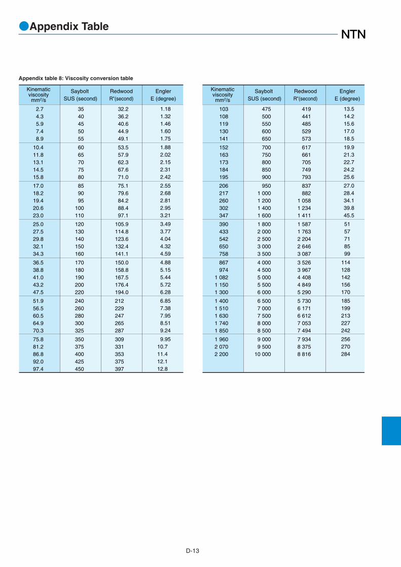
D-13
Kinematicviscositymm2/s
2.74.35.97.48.9
10.411.813.114.515.8
17.018.219.420.623.0
25.027.529.832.134.3
36.538.841.043.247.5
51.956.560.564.970.3
75.881.286.892.097.4
32.236.240.644.949.1
53.557.962.367.671.0
75.179.684.288.497.1
105.9114.8123.6132.4141.1
150.0158.8167.5176.4194.0
212 229 247 265 287
309 331 353 375 397
1.181.321.461.601.75
1.882.022.152.312.42
2.552.682.812.953.21
3.493.774.044.324.59
4.885.155.445.726.28
6.857.387.958.519.24
9.9510.711.412.112.8
3540455055
6065707580
859095
100110
120130140150160
170180190200220
240260280300325
350375400425450
Saybolt SUS (second)
RedwoodR"(second)
EnglerE (degree)
Kinematicviscositymm2/s
Saybolt SUS (second)
RedwoodR"(second)
EnglerE (degree)
103108119130141
152163173184195
206217260302347
390433542650758
867974
1 0821 1501 300
1 4001 5101 6301 7401 850
1 9602 0702 200
419441485529573
617661705749793
837882
1 0581 2341 411
1 5871 7632 2042 6463 087
3 5263 9674 4084 8495 290
5 7306 1716 6127 0537 494
7 9348 3758 816
13.514.215.617.018.5
19.921.322.724.225.6
27.028.434.139.845.5
5157718599
114128142156170
185199213227242
256270284
475500550600650
700750800850900
9501 0001 2001 4001 600
1 8002 0002 5003 0003 500
4 0004 5005 0005 5006 000
6 5007 0007 5008 0008 500
9 0009 500
10 000
Appendix table 8: Viscosity conversion table
●Appendix Table

D-14
0.10200.20390.30590.40790.5099
0.61180.71380.81580.91771.0197
1.12171.22371.32561.42761.5296
1.63161.73351.83551.93752.0394
2.14142.24342.34542.44732.5493
2.65132.75322.85522.95723.0592
3.16113.26313.3651
9.806619.61329.42039.22749.033
58.84068.64678.45388.26098.066
107.87117.68127.49137.29147.10
156.91166.71176.52186.33196.13
205.94215.75225.55235.36245.17
254.97264.78274.59284.39294.20
304.01313.81323.62
1 2 3 4 5
6 7 8 910
1112131415
1617181920
2122232425
2627282930
313233
3.46703.56903.67103.77303.8749
3.97694.07894.18084.28284.3848
4.48684.58874.69074.79274.8946
4.99665.09865.20065.30255.4045
5.50655.60855.71045.81245.9144
6.01636.11836.22036.32236.4242
6.52626.62826.7302
333.43343.23353.04362.85372.65
382.46392.27402.07411.88421.68
431.49441.30451.10460.91470.72
480.52490.33500.14509.94519.75
529.56539.36549.17558.98568.78
578.59588.40598.20608.01617.82
627.62637.43647.24
3435363738
3940414243
4445464748
4950515253
5455565758
5960616263
646566
kgf N kgf N
6.83216.93417.03617.13807.2400
7.34207.44407.54597.64797.7499
7.85187.95388.05588.15788.2597
8.36178.46378.56568.66768.7696
8.87168.97359.07559.17759.2794
9.38149.48349.58549.68739.7893
9.89139.9932
10.0952
657.04666.85676.66686.46696.27
706.08715.88725.69735.50745.30
755.11764.92774.72784.53794.34
804.14813.95823.76833.56843.37
853.18862.98872.79882.60892.40
902.21912.02921.82931.63941.44
951.24961.05970.86
6768697071
7273747576
7778798081
8283848586
8788899091
9293949596
979899
kgf N
1kgf=9.80665N1N=0.101972kgf
If for example you want to convert 10 kgf to N, find "10" in the middle column of the first set of columns on the right. Look in the N column directly to the right of "10," and you will see that 10 kgf equals 98.066 N. Oppositely, to convert 10 N to kgf, look in the kgf column to the right of "10" and you will see that 10 N equals 1.0197 kgf.
〔How to read the table〕
Appendix table 9: Kgf to N conversion table
●Appendix Table

D-15
1/641/323/641/165/643/327/641/ 89/645/32
11/643/16
13/647/32
15/641/ 417/649/32
19/645/16
21/6411/3223/643/ 8
25/6413/3227/647/16
29/6415/3231/641/ 2
33/6417/3235/649/16
37/6419/3239/645/ 8
41/6421/3243/6411/1645/6423/3247/643/ 4
49/6425/3251/6413/1653/6427/3255/647/ 8
57/6439/3259/6415/1661/6431/3263/64
0.0156250.0312500.0468750.0625000.0781250.0937500.1093750.1250000.1406250.1562500.1718750.1875000.2031250.2187500.2343750.2500000.2656250.2812500.2968750.3125000.3281250.3437500.3593750.3750000.3906250.4062500.4218750.4375000.4531250.4687500.4843750.5000000.5156250.5312500.5468750.5625000.5781250.5937500.6093750.6250000.6406250.6562500.6718750.6875000.7031250.7187500.7343750.7500000.7656250.7812500.7968750.8125000.8281250.8437500.8593750.8750000.8906250.9062500.9218750.9375000.9531250.9687500.984375
0.3970.7941.1911.5881.9842.3812.7783.1753.5723.9694.3664.7625.1595.5565.9536.3506.7477.1447.5417.9388.3348.7319.1289.5259.922
10.31910.71611.11211.50911.90612.30312.70013.09713.49413.89114.28814.68415.08115.47815.87516.27216.66917.06617.46217.85918.25618.65319.05019.44719.84420.24120.63821.03421.43121.82822.22522.62223.01923.41623.81224.20924.60625.003
25.40025.79726.19426.59126.98827.38427.78128.17828.57528.97229.36929.76630.16230.55930.95631.35331.75032.14732.54432.94133.33833.73434.13134.52834.92535.32235.71936.11636.51236.90937.30637.70338.10038.49738.89439.29139.68840.08440.48140.87841.27541.67242.06942.46642.86243.25943.65644.05344.45044.84745.24445.64146.03846.43446.83147.22847.62548.02248.41948.81649.21249.60950.00650.403
50.80051.19751.59451.99152.38852.78453.18153.57853.97554.37254.76955.16655.56255.95956.35656.75357.15057.54757.94458.34158.73859.13459.53159.92860.32560.72261.11961.51661.91262.30962.70663.10363.50063.89764.29464.69165.08865.48465.88166.27866.67567.07267.46967.86668.26268.65969.05669.45369.85070.24770.64471.04171.43871.83472.23172.62873.02573.42273.81974.21674.61275.0097540675.803
76.20076.59776.99477.39177.78878.18448.58178.97879.37579.77280.16980.56680.96281.35981.75682.15382.55082.94783.34483.74184.13884.53484.93185.32885.72586.12286.51986.91687.31287.70988.10688.50388.90089.29789.69490.09190.48890.88491.28191.67892.07592.47292.86993.26693.66294.05994.45694.85395.25095.64796.04496.44196.83897.23497.63198.02898.42598.82299.21999.616
100.012100.409100.806101.203
101.600101.997102.394102.791103.188103.584103.981104.378104.775105.172105.569105.966106.362106.759107.156107.553107.950108.347108.744109.141109.538109.934110.331110.728111.125111.522111.919112.316112.721113.109113.506113.903114.300114.697115.094115.491115.888116.284116.681117.078117.475117.872118.269118.666119.062119.459119.856120.253120.650121.047121.444121.841122.238122.634123.031123.428123.825124.222124.619125.016125.412125.809126.206126.603
127.000127.397127.794128.191128.588128.984129.381129.778130.175130.572130.969131.366131.762132.159132.556132.953133.350133.747134.144134.541134.938135.334135.731136.128136.525136.922137.319137.716138.112138.509138.906139.303139.700140.097140.494140.891141.283141.684142.081142.478142.875143.272143.669144.066144.462144.859145.256145.653146.050146.447146.844147.241147.638148.034148.431148.828149.225149.622150.019150.416150.812151.209151.606152.003
152.400152.797153.194153.591153.988154.384154.781155.178155.575155.972156.369156.766157.162157.559157.956158.353158.750159.147159.544159.941160.338160.734161.131161.528161.925162.322162.719163.116163.512163.909164.306164.703165.100165.497165.894166.291166.688167.084167.481167.878168.275168.672169.069169.466169.862170.259170.656171.053171.450171.847172.244172.641173.038173.434173.831174.228174.625175.022175.419175.816176.212176.609177.006177.403
203.200203.597203.994204.391204.788205.184205.581205.978206.375206.772207.169207.566207.962208.359208.756209.153209.550209.947210.344210.741211.138211.534211.931212.328212.725213.122213.519213.916214.312214.709215.106215.503215.900216.297216.694217.091217.488217.884218.281218.678219.075219.472219.869220.266220.662221.056221.456221.853222.250222.647223.044223.441223.838224.234224.631225.028225.425225.822226.219226.616227.012227.409227.806228.203
177.800178.197178.594178.991179.388179.784180.181180.578180.975181.372181.769182.166182.562182.959183.356183.753184.150184.547184.944185.341185.738186.134186.531186.928187.325187.722188.119188.516188.912189.309189.706190.103190.500190.897191.294191.691192.088192.484192.881193.278193.675194.072194.469194.866195.262195.659196.056196.453196.850197.247197.644198.041198.438198.834199.231199.628200.025200.422200.819201.216201.612202.009202.406202.803
228.600228.997229.394229.791230.188230.584230.981231.378231.775232.172232.569232.966233.362233.759234.156234.553234.950235.347235.744236.141236.538236.934237.331237.728238.125238.522238.919239.316239.712240.109240.506240.903241.300241.697242.094242.491242.888243.284243.681244.078244.475244.872245.269245.666246.062246.459246.856247.253247.650248.047248.444248.841249.238249.634250.031250.428250.825251.222251.619252.016252.412252.809253.206253.603
inch
fraction decimal0" 1" 2" 3" 4" 5" 6" 7" 8" 9"
Appendix table 10: Inch-millimetre conversion table
●Appendix Table